Embed Size (px)
Citation preview

2015-16 Capstone Projects Portfolio
Biomedical Computer & Systems
Electrical Industrial & Management
Materials and Mechanical
Engineering Programs
O.T. Swanson Multidisciplinary Design Lab School of Engineering
Rensselaer Polytechnic Institute 110 8th Street, JEC 3232
Troy, NY 12180 (518) 276-2724

Welcome to the 2015-16 Projects Portfolio of the O.T. Swanson Multidisciplinary Design Laboratory at Rensselaer (The Design Lab). In 2015-16, The Design Lab engaged over 390 senior-level students in real-world design challenges, the largest number of students to date and including students studying biomedical, computer and systems, electrical, industrial, materials, and mechanical engineering. These students graduate with the ability to work on teams to solve real problems with multifaceted constraints and deadlines, due in a large part to their activities in the Design Lab. They rise to meet the challenges posed in the Design Lab through their hard work, intellect, and creativity but also through the dedication and engagement of our industrial and individual sponsors, for whom we are grateful for their investments. This year was particularly exciting. We were fortunate to work on engineering problems relating to a wide range of technologies and industries. Examples include the design and manufacture of innovative products, developing environmentally friendly technologies, driving efficiency in manufacturing processes, and improving health and wellness for individuals and groups. Please enjoy this 2015-
16 Design Lab Projects Portfolio, highlighting some of the past year’s projects. The technical breadth and depth of projects presented in this portfolio is impressive. Our sincere thanks to our sponsors, partners, friends, students, staff, and faculty for their time, effort and support of the Design Lab. We look forward to working with you in the very near future. Matthew Oehlschlaeger, Ph.D Associate Dean, School of Engineering Acting Director O.T. Swanson Multidisciplinary Design Laboratory

ENERGY AND THE ENVIRONMENT • Ecosystems of Systems Testing Platform 5 • Low RPM Wind Generator 6 • Cross-Flow Wind Turbine 7 • Wind Turbine Blade De-Icing w/Microwaves 8 • Wind Turbine Reliability Analytics 9 HEALTH & WELLNESS • My Mobility Test 11 • Aids for People with Physical Challenges 12 • Vertical Knee Raise Machine 13 • Wireless Assistive Technology 14 MANUFACTURING, AUTOMATION AND CONTROL • Wingbox Assembly 16 • Additive Manufacturing 17 • Optical Inspection for Cosmetic Defects 18 • WIP and Zipper Sewing 19 • Quench Variability 20 • Augmented Reality System 21
PRODUCT DEVELOPMENT • Peristaltic Pump 23 • CHL Applications 24 • Bath Toy 25 • Design Applications for Light Diffusing Glass Fiber Optics 26 • Wearable Technology for Pulse Rate Monitoring 27 • CubeSat SAA Module 28 • Battle Control System 29
RELIABILITY & TEST SYSTEMS • Pressure Test & Leak Check 31 • Sensor Kit 32 • Smartphone Applications 33 • Strength of Materials Mini Lab 34 • Improved Hook and Loop Test Method 35
• Sponsor Information 36
Table of Contents 2015-16 Capstone Design Projects

ENERGY
AND THE
ENVIRONMENT

Ecosystem of Systems Testing PlatformFall 2015 Team: Anthony Ugarte (ME), Belvia Huo (ME), Kevin Mullin(ME),
Lydia Rebehn (ME), Nicholas Woolf (ME:BME), Yue Yu(ME)
Objectives• Analyze the effect of fan location and design
on air flow• Design and fabricate traverse insertion panel• Update LabView code for the traverse
movement and sensor analysis• Design, construct and perform thermal
analysis on a scaled occupied office setting• Design and fabricate a raised plenum ceiling
for multiple configurations• Simulate airflow and pressure drop ratings of
ceiling panel models
Results and Accomplishments• Fabricated a airtight panel for the traverse to
perform its measurements • Design and fabricated two versions of plenum
ceilings • Ran infiltration analysis on the fully
constructed chamber• Applied the simulated designs for airflow
trajectory and pressure effects for a fan, diffuser and plenum inlet
• Rewrote the LabView code to enable three‐axis movement by the traverse as well as the data acquisition program
• Simulations and models for surface roughness to assess the effects on airflow
• Performed temperature and relative humidity testing on the effect of heating elements
PurposeOur purpose is to provide CASE with a modular test bed to assess a variety of new technologies and provide infrastructure to perform further expected tests.
Background Information• RPI CASE collaboration focused on improving
building practices• Energy consumption• Sustainability and resource
management• Health and quality of indoor air
• Improvement of indoor air quality using biomaterials
Figure 2: ESOS Chamber Elements
Figure 3: Pressure simulation of final inlet duct and diffuser design (pressure drop= 9.62 Pa).
Future Plans• Integration of Velmex hardware into the chamber for tests• Fabrication of the diffuser and acquisition of inlet for the
plenum• Transient analysis of thermal layering effects• Further infiltration testing to improve chamber performance• Design and construct a slotted ceiling panel for further
testing with the traverse
Figure 1: Desiccant absorption test set up
Desiccant Mat Frame
Desiccant Mats
Diffuser
Damper with Controller
Fan
Acrylic Sheet30”
16”
Heating ElementsDiffuser and Plenum InletFanTraverse PanelTraverseCeiling Plenum

Wind turbine schematic. Courtesy of Bharat Bagepalli.
Low RPM Wind GeneratorFall 2015 Team: Anton Andriyanov (MECL), Lauren Brady‐Haskell (ELEC), Thomas Kelly (ELEC), Mike Scocozza (MECL), Arjun Sharma
(MECL), Andrew Skywark (ELEC), Andrew VanBezooijen (MTLE), Christina Vasil (MECL)
Purpose IncreasingturbinerotorsizeleadstoslowershaftspeedspushingtheenvelopeofcurrentGEdesignpractice
SemesterObjectives Considertopologychangestodrivetrain
systems Gearbox Doubly‐fedinductiongenerator
(DFIG) Powerconversionsystem(PC)
Computeperformanceforincreasingpowerconversion
AnnualEnergyProduction(AEP) Windturbinecost
Compareconfigurationsusingrevenue‐costmetric
TechnicalApproach Modelcostofeachcomponent
Gearbox:torque,gearratio,typesofstages,numberofstages
DFIG:increasepartialpowerconversiononrotor,fullpowerconversiononstator
PC:2levelversus3level Developcostconstitutiverelations Evaluateeconomictradeoffbetweengearbox
andDFIG Compareconfigurationsanddetermine
modelwithlowestchangeincostperchangeinrevenue
TechnicalResults Case1gavelowestchangeincostperchangeinAEP(increasingonlybladelength)
Notopologychangeforanylevelofpowerconversion
Reductionratioandfatiguelifeimpactcostandselectionofgearboxconfiguration
Methodologycanbeappliedtoanyname‐platerating,bladesize,orPC%
Accomplishments Developedmethodologytocreateandanalyzecosttradeoffbetweendrivetraincomponents
Evaluatedsensitivityofgearboxratiofor 5%ingearboxcost,asshownabove
NextSteps Considerchangeinnumberofgeneratorpoles Expandmodelstoaccountforbearings,blades,cooling,tower,bedplate,andnoise
Case Bladelength(m) PC% GearboxRatio AEP(MWh)
Base 56.9 30 84 82921 65 30 84 93402 65 40 84 94413 65 40 83 (costoptimal) 9441
2LPowerConverter,2.3MWwindturbine

Cross‐Flow Wind TurbineSpring 2016 Team: Siegfried Boyd Isidro‐Cloudas (MECL & ECSE), Danielle Tavel (ECSE), Kevin Prosicki (MECL), Kyle Pollard (MECL), Matthew Chaet (MECL), Nicholas Blumling (MECL), Thomas Baken (ECSE), Tyler Kessler (MECL)
PROJECT HISTORY•Inherited a benchtop model from previous semester
•Inherited a test site on Folsom Library for final deployment with a Tycon ProWeatherstation deployed on it to collect wind data.
•Previous semester's group had begun development on a pressure sensor telemetry system.
PURPOSETo develop a wind energy harnessing device that performs well in urban environments by minimizing upfront costs and limiting space consumption, noise pollution and rooftop stresses.
SEMESTER OBJECTIVES• Increase system efficiency• Improve inlet geometry to increase
airflow to impeller fins• Design and implement guide vane to
control angle of attack• Improve diffuser design to decrease
air separation and improve pressure recovery
• Improve measurement accuracy
• Finish and test pressure sensor telemetry system to capture data at test location
• Make improvements to current dynamometer system to decrease measurement error
Future Work• Perform additional round of
efficiency testing to validate established data and technique
• Quantify individual efficiency contribution of guide vane and diffuser fins
• Decrease telemetry system net power consumption and deploy at testing location on Folsom Library
• Deploy benchtop model at test site location
ACCOMPLISHMENTS
Pressure Sensor Telemetry SystemDesign and construction of the remote pressure differential measurement system is complete. The system was developed for deployment to the southern wall‐to‐roof edge of the Folsom Library. The system is currently undergoing a series of environmental and site tests to prove expected functionality.
Benchtop Model Improvements and Efficiency Testing
In Red – Terminal ModuleIn Green – Sensor Module
∗ ∗Δ ∗ ∗ ∗
Where:KE , , Δ , ,
0
0.1
0.2
0.3
0.4
0.5
0.6
0.7
400 900 1400 1900 2400 2900 3400
Effic
ienc
y
Angular Velocity (RPM)
Efficiency vs Angular Velocity

Practical Application
Wind Turbine Blade De‐Icing with MicrowavesSpring 2016 Team: Henry Choi (EE), Mengqian Gao (MECL), Kevin Hritz (MECL), Yuyu Hsueh (EE),
Ryan Jenkins (MECL), Kelly Pifer (MECL), Yuhan Shi (EE), Alex Wholey (MATL)
Background and ObjectivesSpring 2015 Feasible Study• Deicing requires: surface heat flux of 1.4kW/m2 ,20‐25
minutes of test period and microwave interactive material
• Options: horn antenna and slotted waveguide antenna at 2.45 or 5.8 GHz
Semester Objectives• Design and test blade‐compatible microwave susceptor
coating layer • Demonstrate effective microwave delivery at 2.45GHz • Build a microwave laboratory test facility and collect de‐
icing data
Microwave Absorbing Materials
Customer: GE Power and WaterBenefits: Increased blade life & efficiency, safer operation of cold weather turbines; decrease turbine down‐time
Microwave SystemMicrowave generation: • Operates at 2.45 GHz• Microwave Power – ~ 1 kW : 60% efficient• Cheap – around $50• Easy to drive – circuits already exist• Air cooledMicrowave delivery options:
Purpose: Investigate the use of microwave de‐icing technology to enhance the performance of wind turbine blades operating in cold environments
1kW Magnetron(2.45 GHz)
Slotted Waveguide
Rime ice
[1] [2]
Microwave Deicing Test ResultsTestbed Diagram
Results: • Ice melted within 30 mins• Test bed ambient temperature remained below freezing
Comparison of Coating Methods
Antenna
Cooling Fins
Voltage Terminal
Problem• G10/FR4 and Ice are transparent to
incident microwave radiationSolution• Susceptor coating on blade surfaceRequirements
• Maximize conversion of absorbed microwave radiation to heat• Withstand cyclic thermal stress• Resistant to UV degradation
Tower Configuration
Blade Configuration
• Arrays of SWAs
• Arrays of horns
• SWA incorporated inside the blade
Slotted Waveguide
1.) "GE Logo." CleanTechnica. N.p., 29 Mar. 2013. Web. 07 Oct. 2015. <http://cleantechnica.com/2013/03/29/new‐ge‐wind‐turbine‐prototype‐revs‐up‐in‐netherlands/ge‐wind‐turbine/>.2.) ReNEWS. "GE Toasts Brazil Milestones." N.p., 26 Aug. 2014. Web. 07 Oct. 2015. <http://renews.biz/73071/ge‐toasts‐brazil‐milestones/>.3) "Magnetrons for Microwave Ovens." ‐ 850W & 1000W Magnetrons. N.p., n.d. Web. 15 May 2016. <http://www.kitchenwareonline.com/magnetrons‐for‐microwave‐ovens‐c102x2263126>.
[3]
• 42 SWAs needed for gain of 9 dBi
• 110 horns needed for gain of 10 dBi• 40 horns needed for gain of15 dBi

Elastomeric Gearbox Mount
Main Shaft Bearing
Wind Turbine Reliability AnalyticsSpring 2016 Team: Yaarub Alnaabi (ME) | Danning Chen (ME) | Ben Coble (ME) | Jeff Daring (ME)
Sam Dickinson (ME) | Peiyang Ding (IME) | Nicole Mowder (ME) | Dillon Scribner (ME)
Main Shaft Bearing
Motivation• GE monitors the operational data on thousands of wind turbines• GE wants to:
• Minimize maintenance costs: service contracts• Identify upgrade opportunities • Improve utility of operational data
Elastomeric Gearbox Mount
Semester Objectives• Develop accumulated damage and lifetime algorithms for:
• Main shaft bearing • Gearbox elastomeric mounts
• Integrate algorithms into operational data• Use models and data to rank components’ accumulated
damageCustomer Requirements• Drivetrain components • System ranking the turbines’ need for maintenance based
on accumulated damage
Loading ModelLoading Model
L10 = expected lifetime [hours]N = shaft speed [rpm]C = basic dynamic load rating [kN] (given constant)P = equivalent dynamic bearing load [kN]
Results: MSB Damage Metrics on Stetson Turbines
Calculate wind speed at different heights with
0.302
∙
Sum incremental forces over swept area for thrust force:
Wind shear moment given by incremental forces:
Gearbox (Front View)
Gearbox (Top View)
y
z
z
x
Results: Elastomeric Mount Damage Metrics on Stetson Turbines
FEA model of elastomer crescent moon shape
Calculate stress on elastomer using loading model
Approximated S‐N curve used for calculating cycles to failure
Comparing stress vs. strain curves of various materials

Health &
Wellness

My Mobility TestSpring 2016 Members: Nicholas Fay (CSE/CS), Alec Vogel (BME/ME), Nicholas Grippo (CSE), Zachary Shute
(CSE), Dan Shanley (CSE), Trevor Corrao (IME), Carson Hynes(CSE), Ryan Delaney (CSE/CS)
• Android and web application developed and functioning, iOS application not fully implemented
• Step counting algorithm implemented
• Security issues identified• Timed Up and Go Test successfully used for analysis
Project History
Technical Accomplishments
Semester Objectives
• Provide an application that collects accelerometer data while taking a TUG test
• Provide a website to access the data collected by the application
Purpose• Over 1/3 of all people over 65 fall
each year• Falling is the leading cause of death
among seniors• 30 billion dollars spent per year in
medical expenses resulting from falls• 25% of seniors have a smartphone
Background• Deploy website to AGS server• Create cross‐platform application
with Ionic• Update MyMobilityTest.com to fix
bugs & failures• Strengthen website to ensure
compliance with HIPAA Title II• Collect experimental data from
senior citizens
Testing/Marketing
Apps
Server
Website
• Performed tests on senior citizens before IRB expiration
• Created a marketing video to showcase the My Mobility Test platform
• Created a hybrid app for iOS using Ionic
• Implemented all Android functionality
• Performed security testing using OWASP ZAP and patched security issues
• Fixed all outstanding security issues• Properly implemented SSL and HTTPS• Updated content on out of date
pages
• Fixed UI bugs• Added new functionality such as
filtering and password reset
• Collected UI feedback from senior citizens
• Transferred the Django website to an external server
• Purchased and set up a valid SSL certificate
• Superseded the existing Android application
Twitter Bootstrap Django Framework Ionic Framework MySQL
Technologies

Engineering Tools• Torque calculation• Circuit analysis• Torque analysis
Term ObjectivesDavid will be able to:• Use arm attachment with more
control • Control gripper via voice control• Independently use device• Have an improved functional device
delivered
Sam LaChance(CSYS)Joe Mauriello(IME)
Sarah Bogdan(ME/DIS)Tom Vaccaro (EE/BME)
Taylor Anderson(IME)Wenjun Jiang(ME)
Chuxuan Chen(CSYS)Sam Hoenes(ME)
Arren Bustamante(ME/DIS)
Aids for People with Physical Challenges
Purpose• Long term: Design devices to
aid disabled persons• Current team: Build a gripper
arm prototype to inherently increase David’s independence
Past Work
Customer RequirementsRequirements Metricsability to reach floor 29”hold a gallon of milk 4lbfast reaction time (from sensing to closing)
4 sec
attached independently No hand use
• Mechanical Gripper• Actuator• Extension Arm
System Overview
• Voice Recognition• Wireless
Compatibility• Driver Control
• Material• Latching• Padding• Dock & Charger
Difficult to:• activate gripper• put device on• lift heavy
objects
• Designed arm attachment to be operated independently by David
Arm Attachment
Control
End Effector
Future Work
Engineering Tools• Muscle model• Sample code
Engineering Tools• Force analysis• Materials selection• Torque analysis
Physical Prototypes
• Further testing with David• Manufacture with final materials• Deliver assembled device• Redesign for universal use
Requirements• Independent use• Withstand 32lbs
Requirements• Detect client signal• <1% false positive• <2sec response
Requirements• Hold 8lbs• Full range in<1s• Open 4in.

Vertical Knee Raise MachineSpring 2016 Team : Ralph Bonilla (ME), Ryan Buchovecky, (ME), Jeremy Carr (ME),
Maeve Conway (ME), Michael Croke (ME), Chris Holomakoff (ME), Tim Maisonet (ME), Michaela Mariquit (ME), Madhav Venkaswamy (IME)
Purpose: Design a home VKR machine that allows for easy storage and set‐up. Workouts on the machine increase abdominal girdle strength, which decrease chronic lower back pain that 80% of Americans experience during their life.
Project History:• Alpha prototype is a single upright beam design• Design and material issues causing the base to bend when
under loading• Arms of the machine need to be completely removed for
storage
Semester Accomplishments:• Defined “stability” in the context of this project• Evaluated two preliminary designs: upright beam and
tripod• Presented a recommendation to the sponsor based
on analysis of customer requirements• Pursued final design in accordance with the sponsor• (Figure 1)• Used FEA to confirm the machine meets ASTM
Standard F2276: Standard Specification for Fitness Equipment
• Constructed a beta prototype of final design• Performed cost analysis and created a
comprehensive business plan for 10,000 units
Customer Requirements:
Recommendations:• Find a manufacturer and facility• Determine most cost effective production and
shipping methods• Find laboratory to conduct physical ASTM testing• Develop pitch for potential investors
Figure 4: Folded Side View of Tripod
Requirement Spec Value Test ValueMachine Weight < 50lb 60lbMax User Weight 275lb 285lbSet‐Up/Break Down Time
< 15sec 11.7/10.6 sec
Folded Dimensions 1’ x 4’ x 6’ 0.67’ x 1.88’ x 5.67’Manufacturing Cost
$250/unit
ASTM StandardLoading
300lb dynamic load with a safety factor of 2.5
Passed according to FEA
Fatigue Life 10 years 11.36 yearsDeflection < 0.75” total, < 0.5” in arms 0.737”
Figure 2: Side View of Tripod
Figure 1: Final Design
Figure 3: FEA Results of Max Deflection
0.737”

CUSTOMER REQUIREMENTS AND PAYOFFS
Spring 2016 Team: Jason Flanagan(EE/PHY), Yuhong He(EE), Toshimitsu Kishi(MECH), ZihengLi(EE), Emily O’Neill(EE), Erik Vink-Lainas(EE), Talha Yilmaz(EE), Alexander Yin(MECH)
Wireless Assistive Technology
• Design and build an Android application for command of output system
• Implement two input methods to control the same output.
• Have Bluetooth communication between input and output methods.
• Integrate inputs with designed and already existing outputs
• Work with the Gizmo team to integrate two projects
System Architecture
Results and AchievementsDESIGN SOLUTIONS
• Seamless connection between inputs and outputs
• Ability to be implemented into current systems
• Modular system that can be customized for a multitude of unique disabilities
• Support the independence of elderly and disabled individuals
• Customers will gain their independence to accomplish simple everyday tasks
SEMESTER GOALS
• New project stemming from previous projects assisting the disabled and elderly
• Based on 2012 disability study
-- 7.8 million have a self-care disability
-- 16.2 million have independent living disability
• Typically disabled and elderly individuals have a fixed budget
• Wired joystick control on PSoC and could wirelessly control output devices
• Demonstrated wired voice control on Arduino with selectable outputs
• Android application could wirelessly control output methods using a voice control and touchpad interface
• Design of refrigerator opening mechanism
• Examine the possibility of combining the main system and Android so that the Android acts as the main system
• Implement cloud storage of input and output device states
• Use Wi-Fi to provide wireless connectivity between input methods and output devices
• Continue system integration with new input methods and output devices
Application Development
• Incorporate various input methods including a joystick and voice control
• Use commands received from an Android application to control output devices
• Design and utilize “off the shelf” output devices
• Implement wireless communication with Bluetooth
FUTURE PLANS
RESULTS AND ACHIEVEMENTS
Joystick input Voice Control Input
Goals APPROACHBACKGROUND INFORMATION
Microphone
Arduino
Joystick
Bluetooth
PSoC

MANUFACTURING
AUTOMATION
AND
CONTROL

Develop an autonomous or semi‐autonomous system to perform various tasks required for the manufacture and maintenance of airplane wingboxes. Reduce need for human work inside wingbox, increasing efficiency, safety and decreasing costs.
Purpose and Motivation
Boeing Wingbox AssemblyFall 2015 Team: Zach Baierl (MTLE), Connor Finnell (CSE), Michael Macarevich (CSE), Samuel Nathanson (ME), Robert Orban (ME),
Abdulaziz Shamsah (ME), James Whelan (IME)
Past Work
Combined system analyzing a sealant bead.
Final System
Past Work
Design and builda prototype endeffector, to houseand expand uponthe inherited system, for postapplication analysis of bead sealants as applied to butt seams.
• Computerized Visual Inspection System• Computer analysis of bead geometry
• Housing• Contain camera, laser, and
supporting hardware in one unit.
Past Work
aThe small dimensions of the wingbox make ahuman performance of tasks such as laying aand inspecting sealants difficult.
Utilizing a separate camera and laser, a foundational bead analysis system was created by previous teams with widthanalysis capability.
Length
Access Port
Spar Heights
Confined Space: The Wingbox
Inherited System
Main Semester Objective
Sub Systems
Technical ApproachLaser
Camera
CVIS Results and Final Housing

Physical System and Design Constraints
Additional Requirements● Parking location and attachments do not interfere with
laser path● Spreading device rides above Top Plate● Parts survive vacuum pull, chamber temperature 40 C ‐ 300
C● Spreading system integrates with existing installation plan● Design motor controller to position spreading device with
ball screw● Team semester budget of $1000
Additive ManufacturingSpring 2016 Team: Tim Faulkner (ME), Antonio Fernandez (EE), Kevin Guo (ME), Marty Hoskins (ME), Stanly
Mathew (EE), Jay Reddick (ME), Michael Robinson (ME), Natalie Tremblay (ME)
Purpose:To develop a robust selective laser melting (SLM) 3D printer that implements a closed
loop feedback system to produce high quality, repeatable 3D parts.
Semester Objectives:To design and prototype a functional powder handling system concept that distributes metal powder to produce a
repeatable, thin layer and measures the powder layer to detect irregularities.
Design and Research
Measurement system for Surface Irregularities
3D Printer Flow Chart
Motor and Ball Screw to Drive Spreading Device
Hopper Concept
Past Work● Narrowed Additive Manufacturing to
powder‐based SLM 3D printer● Comparison of various powder spreading
techniques for cost, dealing with irregularities, compaction, complexity, lifetime, and maintenance
● Wiper blade failure analysis
Future Recommendations● First construction of design should be made out of
aluminum for initial testing and demonstration of functionality
● Narrow down the necessary requirements expected for the measuring system
● Develop velocity profile based on system load for accurate motion control
● Need to figure out temperature at locations within the vacuum chamber
Laser Point Profilometer ● Uses Cmos technology and lasers to recreate a 3D plot of the build surface for deformities
● The most accurate sensor among those considered
● Easily modified to withstand chamber conditions
● Main Hopper Body for Transport and Storage of Powder● Pocketed Roller for Powder Dispensing● Counter Roller to Level Powder● Rack and Pinion to move the hopper one direcion and
create a reverse direction rotation for the counter rotating roller

Optical Inspection for Cosmetic DefectsSpring 2016: Gregory Grebe (EE/CSE), Huiye Liu(EE/CSE), Mengziying Tu(EE), Stefan Ryan(EE), Tyler Murtha(CS/CSE), Victor Yu(EE), Youxin Li(EE)
Jabil, the world’s third largest supply chain management and manufacturing company, seeks a recommendation for a real time system to inspect products for cosmetic defects in an attempt to reduce inspection time and cost.
Purpose
Semester Objectives
Recommendation of Future Steps
Accomplishments
To formulate a recommendation on the use and implementation of a neural network software on the production lines of Jabil for defect detection
• Test ViDi Red Supervised and compare to Unsupervised• Test with Jabil’s products, or products that more closely simulate the defects Jabil is looking to find• Implement/Evaluate a custom application using the Training API• Build an application to simulate training and processing on a production line environment
Person on Line
Decide Good/Bad
No
Retrain Model
Capture Image
Product on Line
Yes
RetrainCondition
Task Why important Results Conclusion
Deterministic Test Test to explain the deviation in the output of ViDi’sneural network Output varied by 1‐2% ViDi is non‐deterministic
Training Set Variation Test
Test for if random selection is as effective as specific selection for image variance
Results improved when selecting images to train on a wider image variation
It is advisable to select images in order to capture variations between images
Orientation Test Test to see if ViDi can handle different views of a product Error rates were very high
When including many views of a round, patterned object, ViDi has a hard time differentiating between images
Parameter Test Test 5 important parameters to see how they affect processing time and error rate
Gained characteristic trends for each parameter with error rate and processing
time per imageFeature size was the most important parameter to tune
ViDi Blue Rotation Test
Test ViDi Blue’s capability of rotating images to align feature points to increase image consistency Rotation is possible For round patterned objects, rotation can be done using
feature points ViDi Blue cropping
TestTest ViDi Blue’s capability of isolating feature
points for cropping in ViDi Red Cropping is possible, error rates and
processing time per image much lowerIsolating features in ViDi Blue and cropping around them
with a predefined box is very advisable
Database Export Custom App.
Evaluate the API by creating an application to process a large dataset of images
API is simple to use, and the results received are the same as seen in the GUI
The API must be used in order to process a single new image. Custom applications can streamline the process.
Camera Capture Custom App.
Determine how to integrate a camera with ViDithrough a custom application
OpenCV can be used to interface a camera and process the images captured
A custom application must be created in order to interface ViDI with a camera, but it is not difficult to accomplish
Data Set 1; G 167 B 44
Data Set 1; G 95 B 48
Data Set 1; G 100 B 50
Data Set 1; G 100 B 50
Data Set 1; G 267 B 44
Data Set 1; G 50 B 50
Data Set 1; G 50 B 0
BadBad
GoodGood
GoodGood BadBad
GoodGood
……
DATABASEDATABASE
Remove Human and Deploy
ModelAcceptable
Yes

• Zipper• Integrate a solution to allow all zipper
sewing to be carried out by visually impaired employees.
• WIP• Update Bill of Materials• Update WIP Inventory Spreadsheets
• Vest Styles 707,719• Neck Tab Styles 1620, 1649, 2215, 8105
• Create Tally Sheets for Inventory Count• Assess Mfg. flow and identify
improvement areas
NABA WIP and Zipper Sewing
• Northeast Association of the Blind at Albany (NABA) provides employment and rehabilitative services to visually impaired individuals.
• Design, test, and implement a sewing fixture that enables visually impaired employees to attach zippers to vests.
• Improve NABA’s workforce to 80% visually impaired employees.
• Make EOY inventory counting process take less time and counting easier.
Background
Purpose
Accomplishments
• Zipper• Final guide implemented at NABA • More guides ready to be made as NABA
needs• WIP
• Spreadsheets for Raw Materials, 707 & 719 Vests and 1620, 1649, 2215 & 8105 Neck Tabs
• Created Tally Sheets for standardized counting
Recommendations
• Zipper• Look for a better way to feed pull tab zipper into
guide• Use experienced sewers to teach less
experienced sewers to use the guide• WIP
• Incorporate 5S/Lean Manufacturing principles to better organize bins of WIP goods
• Count Inventory multiple times a year
Semester Objectives
Technical Approach
• Zipper• Design, build, and quantify success for zipper
attachment guide.• Decision matrices and prototype iteration.
• WIP• Verify BOM, test WIP inventory spreadsheets.• Reduce number of workstations with
accumulated WIP inventory during a count
Figure 1: Screenshot of 707 WIP Spreadsheet Figure 2: Visual of Vest Workstations, in red, that should have accumulated WIP inventory during EOY count
Table 1: Decision matrix for final design.
Final Guide with long vest clamp
Final Guide in use at NABA
Spring 2016 Team: Eric Benaim (IME), Eric Acchitelli (IME), Christopher DiNicola (IME), Ethan Wolf (IME), David Hecht (IME), Jonathan Underwood (MECH), Peter Hudson (MECH), Paul Lentine (MECH)

Semester Accomplishments● Statistically supported hypotheses for
quench variability● Determined how the surface finish of
the wire correlates to slippage● Analyzed how environmental humidity
affects the wire‐to‐epoxy bond strength● Measured moisture build up within the
epoxy and test how this affects bondingcapabilities
Background● MRI Superconducting magnet cooled with
liquid helium to 4K● Quenching is a massive helium boil off● Caused by small increase in temperature● Slips in wire‐epoxy create frictional heat● More common during humid summer● Quenching costs time and money
Recommendations● Reduce local humidity around cured/curing magnet● Finish winding magnet in one session● Switch to wire supplier with roughest surface● Blow heat on wire to remove adsorbed water
Technical Results● Humidity is absorbed into epoxy and DMD● Humidity reduces wire‐epoxy bond strength,
determined by slip testing● Wire suppliers have chemically similar surfaces,
determined by spectroscopy● Supplier with roughest wire provided highest bond
strength, determined by microscopy
Quench VariabilitySpring 2016: Adnan Alodaini (ME), Austin Amery (ME), Olaf Bergeson(MTLE), Gregory DiGuido (ME),
Shams Khondkar (MTLE/BMED), Colin Krum (ME), Beth Lotterer (MTLE), Nathaniel Miller (ME)
Purpose:• Evaluate the reason(s) for increased quenching from June to September and provide
suggestions/solutions to reduce/eliminate magnet quenching
-21.26%
+12.90%+5.43%
+6.92%+5.56%
-14.37%-6.18%
-0.04%
-14.66%-14.83%-9.50%
-27.68%
0.000
5.000
10.000
15.000
20.000
25.000
30.000
35.000
Aver
age
Stre
ss (M
Pa)
Red = Control, Green = Statistically Significant, Blue = Not Statistically Significant
Mitigating Seasonal VariabilityMitigating Seasonal, Wire Supplier & Process Variability
Current Quench Frequency
Moz
art Q
uenc
h Fr
eque
ncy
Months of the Year
Mitigating Wire Supplier & Process Variability
New sample design for Tensile Test
EPOXY
WIRE
Slip Test Underway
Philips Core During Manufacturing
High Humidity Chamber
99
Reaches and Maintains a Relative Humidity of 99%
Water
Humidistat
Reaches and Maintains a Relative Humidity of 20%
Desiccant
Humidistat
8==>
Low Humidity Chamber
20
Aid Raytheon technicians in assembly, and repair of circuit card assemblies (CCA’s) by providing a system that will track the CCA’s, identify and locate any selected parts on the board, and provide instructions for installation of selected part. This will increase efficiency and reduce errors made by technicians, reducing the cost of CCA production
Augmented Reality SystemSpring 2016: Michael Albert(CSE), Thomas Eyre(CSE), Dan Foster(EE/CSE), Michael Li(CSE),
Jaylen Thompson(EE), Luke Travis(CSE), Yilan Xu(EE/CSE), Zhengjie Zhang(CSE)
Purpose Technical Approach
Figure 2: Diagram of implementation of Camshift tracking algorithm
Figure 1: Current Interface layout
Future• Clean and polish the new GUI features• Add unit testing for tracking speed and
functionality of ARS• Continued optimization to tracking speed
00.20.40.60.8
11.2
0 15 30 45 60 75 90105120135150165180195Rat
io o
f Mat
ched
&
Tota
l Key
Poi
nts
Board Angle (degrees)
Detection Error vs. Board Angle
Current GUI
Figure 3: Detection Error Measurements as Performed on Arduino UNO
Overlay Imaged on Tracked Board
Component Selection Marker
Accomplishments• Updated GUI with resizable, moveable, and
dockable tool windows for a more customizable user environment
• Replaced previous fiducial tracking algorithm with a combination of Camshift and feature detection for increased speed, accuracy and versatility
• Developed experiments to perform unit tests on tracking algorithms with minimal outside variability
• Created a new installer program that can install all necessary third party software, a compiled ARS program, and all associated files

PRODUCT
DEVELOPMENT

Periodic Rotation Design Side View
Rack & Pinion
Cam FollowerShaft
Roller Assembly
Linear Guide
Carriage
PURPOSE: TUBE ROTATION TECHNICAL APPROACH:
Fall 2015: Danielle Balzano (MECH), Saeed Hakim-Hashemi (MECH), Kori Heisler (MECH), Zachary Konopaske (MTLE), Andrew Welsh (MECH), Lauren Oesterle (MTLE/BME), Kailei Xu (MTLE)
akim-HashH), Lauren
Peristaltic Pump
FUTURE WORK:
• Conduct tube lifetime testing• Study the affect of the clamp material
and the tube holder configuration on tube rolling
• Create tube translation prototype• Engage in a manufacturability study
Tube Rotation Concept Designs:
• Tube rotated 100° while pumping water• Rate of axial movement affected rotation
• Size Constraints: • X: 185 mm• Y: 156 mm• Z: 108 mm
• Tube rotation rate• No more than
180 tube rotation per hour
• Axial movement• Precision:
Minimum step size 1mm +/- .5mm
• Prototype Lifetime• 6 months
Engineering Requirements:
Middle Position Far Left Position Far Right Position
• Conducted a test using blue ink• Top picture indicates the control test• Bottom picture indicates tube rotation
test• Ink smears around the circumference of
the tube indicate tube rolling
Design Features:
• Compact: Overall length increased by 2cm• Front end components unchanged• Adaptable Drive System: Can control
distance, speed, position• Retained existing shaft drive system
for rotation
• Design and build a modified peristaltic pump with automatedtube rotation during operation
• Determine a viable concept for tube translation using the newest peristaltic pump model
Create a mechanical design to support PerkinElmer’s conceptual plan for extending tubelife of a Peristaltic Pump.
TUBE TRANSLATION CONCEPT:
PERISTALTIC PUMP:
SEMESTER OBJECTIVES:
Clamp
Roller Assembly
Fluid In
Fluid Out
Tube Holder
Pinching
Tube Cross Section
Final Design Down-Select
Tube Translation
Tube Rotation
• Feasible tube translation concept design was created• Tube rotation design overcame the challenges of integrating an independent
drive system with a rotated shaft in a compact space• Demonstrated a working prototype that achieved 120° tube rotation• Adjustable prototype operation can evaluate test parameters for optimization
RESULTS:
Tube Rotation Distance & Forces:
Grey-Grey Tube O.D.: 2.90 mm
(Tube O.D.)
Length of roller motion 2.90 =
ACCOMPLISHMENTS TO DATE:
Cam Follower
Linear Guide
Rack & Pinion
Grooved Shaft
• Cam Follower transfers axial forces to rotating shaft
• Linear guide transfers forces from Rack & Pinion to Cam Follower
• Rack & Pinion provides independent, highly controllable axial motion
Hybrid approach between rack & pinion and cylindrical cam designs
Ease of Manufacturing and Assembly• 7 additional parts:
• 4 off the shelf – High Tolerance• 3 manufactured – Low Tolerance
• Linearly stacked assembly
44°
• Tube Travel Distance: 20mm
• Range of motion: 44° (0.77rad)
• Required torque of the new motor:
0.34Nm (single tube)
See-Saw Design Features:
Tube Rotation Drive System Overview:
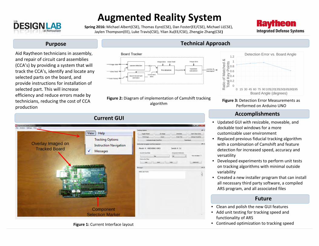
CHL ApplicationsFall 2015: Loren Cao (MGMT/MECL), Graham Harris (MECH), Tomas Gutierrez (MECL), Maureen Leavy (BME), Nolan
Quinn (MECL), Julian Yuen (EE)
Purpose and Objectives• Characterize and quantify the dynamic conductive hook and loop electrical
and mechanical properties of VELCRO® brand fasteners to determine the potential of the material.
• Goal of this project is to utilize conductive hook and loop as a necessary component in a marketable product to be incorporated in the classroom.
Test Results
● Carbon Loaded Polymer (VELCRO®) CHL higher in resistance, higher in retention force than silver coated nylon (LESS_EMF) CHL
● Resistance minimum doesn’t change, but low resistance retention degrades over cycles
● Carbon Loaded Polymer (VELCRO®) has a smoother shear force profile due to higher rigidity in hooks
● Resistance approaches a minimum when the shear force over CHL interface is at a maximum
● Replicates actual user interaction when and usage cycles● Carbon Loaded Polymer● (VELCRO®) CHL degradesmechanically much less thansilver coated nylon(LESS-EMF) hooks in peelconfiguration● Most retention forcesstay above 50% of originalvalue after 5000 cycles● Carbon Loaded Polymer(VELCRO®) cyclical forceaverages and resistancerelationship maps transientmechanical degradationto resistance increase.
Test FixturesTension (Normal) Testing Fixture
Peel Testing Fixture
Shear Testing Fixture
Interactive Board Prototype
• Board utilizing CHL as both an electrical connector and a fastener
• Each connection connects to a Raspberry Pi utilizing digital inputs
• Digital inputs converted to decimal to perform operations
• Demonstrates a promising application of CHL for marketable use
Tech Approach
Future Work Suggestions● Possible Tests: Thermal effects on mechanical testing, higher test count to formulate a
standard deviation, maximum allowable current, testing different combinations of hook and loop types, mathematical governance of force and resistance, utilization as a piezoelectricalsensor
● Form a standard of product performance through the utilization of the peel fixture (cycles of usage, durability)

Bath ToySpring 2016 Team: Andrew Brumer (MECL), Michael Leszczynski (ISYE), Elliott McFarland (MECL),
Taylor Miller (MECL), Jose Resendiz (MECL), Reid Roberge (MECL), Morgan Schweitzer (MECL), Sierra Weiss (MECL)
Project PurposeProject Purpose System RequirementsSystem Requirements Technical AccomplishmentsTechnical Accomplishments
Past WorkPast Work
Future Recommendations Future Recommendations
• Create a water‐recirculating toy that allows children to safely play with running water
• Toy is self‐pumping and provides multiple water outlets, unlike competitors
• Patent # 8156578 covers the concept of a recirculating bath toy with interactive features
• Computer models of casing and few interactive accessories
• Normal Use and Abuse testing requirements and guidelines in ASTM F963‐11
• 3 L/min to 12 L/min of waterfall• A minimum of 3 interactive features to vary water flow
Figure 1 ‐ CAD model of initial concept
Figure 2. “Bath Toy” Exploded view of final design
Casing Faceplate
Peg Board with Waterfall outlet
Showerhead with a push/pull control
Accessory Pegboard Toys
Submersible Centrifugal DC pump
Casing Back Plate Polyethylene Tubing
Hose attachment controlled with a twist valve
Subsystem Accomplishments Casing Modified profile of original design to
add structural stability & internal geometries to aid in subsystem waterproofing
Inserts Integration of functional snapfit to bucket and waterwheel assemblies
Showerhead 1.5 m/s velocity at outlet Hose 2.5 m/s velocity at outlet Pegboard/Waterfall
Eliminated separate waterfall features– lowered PIM cost.
Internals Final experimental water flow of 66.7ml/s was within the range stipulated by the patent (50‐200ml/s)
Table 1 – Bath Toy Project Subsystem Accomplishments
• Change flow rate (1440GPH) to reflect intake from a ½” diameter 25’ length garden hose to achieve desired feature effects
• Apply soap to outside surface of pegboard or prepare soapy water to break surface tension of hydrophobic polyethylene
• Apply dental or candle wax to hose and showerhead features to mitigate leaks
• Demonstrate the prototype in three stages: waterfall operational only, showerhead and waterfall operational only and water and hose operational only
• Select an appropriate medium to present the prototype (video vs. physical demonstration)

Reflectivity SolutionsReflectivity SolutionsDevelop Enabling Technologies• Low cost, end of fiber reflector to achieve uniform
light distribution throughout length: efficiency > 50%• Practical mounting solutions to aid in FibranceTM
installation within architectural applications
Design Applications for Light Diffusing Glass Fiber OpticsSpring 2016: Joel Ahearne‐Ray (MTLE), Heather Danielsen (MECHE/DIS), Andrew Groskopf (EE/CSE), William Howard (MTLE),
Levi Kennedy (MECHE), Jacob Morales (MTLE), Elena Steffan (MECHE/DIS), Juancarlos Vivar (MECHE),
Purpose
Project History Mounting Testing Results
To increase the customer base of FibranceTM (Light Diffusing Fiber) for Corning, through applications in the automotive and architectural industries.
Semester Objectives
The Fall 2015 FibranceTM Team:• Developed a catalog of potential applications • Investigated Fibrance™ applications in automotive
and architectural markets • Wall decorating• Semi‐Trailer Advertisement• Tabletop Decoration• Crosswalk Lighting• Foot Well Lighting• Chandelier
• Prototyped a laser control unit and an application deployment tool
• Designed components for mounting and researched methods of adherence
Shear and tensile strength tests on adhesive and material combinations:
• painted drywall, wood, vinyl plastic, and steel
• Super Glue, Epoxy, and UV Curing
Aluminum/ Plastic Sleeve
Highly Polished Aluminum Cap
Hole for FibranceTM
Pressure fitted shape with .030in diameter to hold FibranceTM in
place with friction
Attaches to tip of adhesive bottle to distributes glue evenly
behind the Fibrance TM in contact with the surface
Ergonomic handheld device to cure BondicTM to desired surfaces
Deployment device that attaches to arm to install FibranceTM in a
user‐friendly manner
Mounting SolutionsMounting Solutions
Reflectivity Testing Results
Adhesives
Prototyped hooks to test the fit with FibranceTM. Learned thatthe FibranceTM will require an adhesive to hold it in place basedon the tolerances and compliance of both the fiber and hooks.
Tested for full curing of12 LEDs, 30° viewingangle, spaced 0.609inat a velocity of 1.8 in/s
Hook & Rail
UV Curing
Applicator TipHook & Rail
Spool
End of FibranceTM lays flush against reflective cap
Straight Mounting Solution
Hot Glue Deployment Tool
Curved Mounting Solution
UV Curing
Gallium Reflective SleeveGallium Reflective Sleeve
Testing Plastic Coverings
Adhesive Testing Setup
Hook Corner Testing
FibranceTM CorePVC Exterior Gallium
Coating
Gallium Solidification Times
Room Temp (22 °C)
Cool Tap Water (12 °C)
Solidification Time >30 Minutes 1‐2 Minutes
30‐53% Reflectivity 20‐33% Reflectivity
Used a photoresistor to measure the light along the lengthof FibranceTM. Took multiple measurements at 6 inchintervals, averaged, and then graphed the results.

Spring 2016 Team: Shane Conaboy (EE/CSE), Bingqian Dai (EE), Shuang Feng (EE/ME), Ato Fynn (EE), Ryan Gagnon (CSE), Gregory Herman (EE/CSE), Daniel Kloss (ME), Matthew Senneca (EE)
NEXT STEPS• Continue filtering circuit tests to
improve SNR• Improve algorithm• Finalize PSoC 4 BLE prototype• Implement digital filtering
CURRENT SEMESTER OBJECTIVES
1. Design and implement a PPG signal filtering circuit to maximize the SNR
2. Develop a robust heart rate detection algorithm that functions with low SNR’s
3. Creation of reference architecture and final prototype for the PSoC 4 BLE.
TECHNICAL RESULTS• Design and test results of signal filtering
circuit• Algorithm design, simulations, and PSoC
5LP & 4 BLE testing with desired BPM output
• PSoC 5LP prototype
PURPOSEDevelop a reference architecture and prototype for a wearable heart rate detection device and prove that the PSoC4 BLE can successfully detect heart rate under real world conditions.
ALGORITHM FLOW DIAGRAM
PPG Sensor
Signal Filtering Circuit
Accelerometer
Software Algorithm
Terminal Output
SD CardPulse
LED Display
FILTERING CIRCUIT OUTPUT SIGNAL
MATLAB SIMULATION OUTPUT
PSOC 5LP PROTOTYPE
SIGNAL FILTERING CIRCUIT
FULL SYSTEM DIAGRAM

• Design a SADA module using COTS components to NASA TRL 3:A. Space‐grade paper design B. Prototype that demonstrates:
1. Specified panel rotational speeds2. Sun and/or light tracking capabilities
• Allow for maximum power generation for CubeSat
CubeSat SADA Module (2)Spring 2016 Team: Arnold Ahnood (EE/CSE), Alexander Buchholz (EE/CSE), Dylan Carberry (ME), Brandon Chun (ME), Niyati
Desai (EE), Kevin Doremus (EE/CSE), WeiXuan Lai (ME), Christine Marini (ME)
Figure 1: Deployed SADA [IPSPT 2014]
Purpose
Design Requirements• Device mass: < 1 kg• Device Size: < 1/4U (10 cm x 10 cm x 2.5 cm)• Maximum total mass of solar panels: 3 kg• Pointing Accuracy: < 0.0175 radians (1°)• Panels have continuous rotation about 1 axis• Rotational Speed: Between 3.6x10‐5 and 2.4x10‐3
rad/s
Background Information• CubeSats are compact satellites
• Small size, low weight, lower launch costs, cheaper and faster development
• 1U = 10 cm x 10 cm x 10 cm• Solar Array Drive Assembly (SADA) is an option
to maximize power generation for CubeSat
Figure 2: Device Overview Flowchart
Figure 3: CAD Assembly (Left) and Assembled Prototype (Right)
Subsystems• Motor/Gearhead (Red)• Transmission • Control (Blue)• Chassis (Gray)• Hinge/Deployment Mechanism (Purple)Note: Colors correspond to Figure 3 – CAD Assembly
Testing/Simulations
Component Prototype Space Grade
Motor (A) Micromo AM124 Stepper Motor
Micromo AM124 Stepper Motor
Gearhead (B) Micromo 15A Planetary Gearhead
Micromo 15/10 Planetary Gearhead
Encoder (C) US Digital MA3 Encoder N/A
Primary Shaft (D) 6061 Al 6061 Al
Secondary Shaft (E) Steel 6061 Al
Gears Nylon Bulk Metallic Glass
Sleeve Bearings PTFE/Rulon J PTFE
Slip Rings (F) Adafruit (Prosper) Electro‐Miniatures or CobhamAeroflex
Microcontroller/ Motor Driver (G) Polulu B‐328
CubeSat Controller/ International Rectifier RH
Motor Control Module
IR Sensors (H) LTR‐4206E N/A
Table 1: Prototype and Space‐Grade Parts/Materials Selection
A
B
C
D
E
E
F
F
G
H
H

Battle Control SystemSpring 2016 Team: Daniel Baek (CSE), Hamilton Carpenter (CSE), Forest Crossman (EE), Alessandro Galli(CSE),
Cyril George (EE/CSE), Abigail Gillett (EE), Nayo Ogilvie (EE/CSE), AJ Tate (EE), Mason Watts (EE/CSE)
Project Future• Further research into implementation/purchase of the
investigated networking solutions• User driven UI system design and implementation• Creation of RTAP software based on the ideas and
requirements recorded during this semester
Semester Objectives• Document and define System Requirements
and system Use Cases• Evaluate modern networking technologies to
determine which may be valuable to the RTAP• Implement software to demonstrate a
working transfer of aircraft data and display amock UI
• Write documentation for use of demo system
Project History• NORAD has monitored US airspace since 1958
using various monitoring systems• Existing system developed by Thales‐
Raytheon• Current iteration finished in 2011
PurposeDesign, build, and test an updated version of theNorth American Aerospace Defense Command’sRemote Tactical Air Picture (RTAP). This systemis used to monitor the airspace of the US andCanada. The existing system was built as a proofof concept and has high costs associated withadding new sites to its network.
Collection SiteRome, NY
Collection SiteTyndall AFB, FL
Collection SiteElmendorf, AK
Viewing SitePentagon
Viewing SiteNORAD
Viewing SiteCanCMD
Existing Architecture
Collection SiteMcChord, WA
Viewing SiteNCRCC
# # #
Collection SiteRome, NY
Collection SiteTyndall AFB, FL
Collection SiteElmendorf, AK
Viewing SitePentagon
Viewing SiteNORAD
Viewing SiteCanCMD
Sample Architecture
Collection SiteMcChord, WA
Viewing SiteNCRCC
# # #
Redundancy • Backup data storage• Redundant connections
Cost• Scalability• Decrease P2P• Decrease # of Servers
Real Time • Display Air Picture• Refresh rate < 2 seconds
Major Requirements
Networking Technologies• OSI Model Layers 1‐4 technologies were researched
and analyzed based on System Requirements• Coax and Fiber based transmission lines• Cloud‐based technologies: Multiprotocol Label
Switching (MPLS) and Carrier Ethernet (CE)• Standard Internet Protocols: User Datagram Protocol
(UDP) and Transmission Control Protocol (TCP)
Layer 1 Coax FiberLayer 2 MPLS CE ATMLayer 3Layer 4 UDP or TCP
Workstation Enhancement• Improving the user’s workstation could help them complete
their mission more effectively• Major areas of research include:
onlinemarketinginct.com/wp‐content/uploads/2015/07/Siri‐Search1.jpgd3nevzfk7ii3be.cloudfront.net/igi/in1WqvSDlbQLvTiM.medium
Voice Recognition SoftwareVirtual Reality
Platform Technologies• The RTAP client application will need to run on Desktop and
Mobile platforms.• To fulfil this and other requirements, we have determined
two possible solutions: Native applications and Webapplications.
Cross‐platformReal Time
Platform Requirements
Native• High‐speed• Low latency
Web• Slower, but
fast enough
Web• Web
standards
Native• Qt, Java• Compile for
each platform
Cloud WAN

Reliability &
Test Systems

Pressure Test & Leak CheckFall 2015: Teo Camadella (ME), Tyler Cassidy (IME), David Dunalewicz (ME), Timothy Piette (MTLE), Connor Rhoads (ME), Patrick Strohbeen (MTLE), Elizabeth Wayne (ESCI/BMGT), Jonghyuk Yoon (ME)
Purpose: Design and deliver a streamlined and repeatable process that will reduce overall lead time variability across the 4K area: 4K Pressure Test (4KP), 4K Leak Check (4KL)
4KP Purpose:• Structural integrity of magnet• Detect gross leaks (> .1 mbar*L/s)
4KL Purpose:• Structural integrity of magnet• Detect smaller leaks (> 5 x 10‐6)
Current setup ‐ Outside in‐Pump vessel down to 10‐3 mbar – Vessel in helium rich environment‐Detect helium leaking into magnet‐Proposed upgrades with their respective time savings per magnet:
Semester ObjectivesAssess current equipment and methods during 4K test operations
• Suggest equipment upgrades and process configurations
• Integrate 4K Pressure Test and 4K Leak Check stations
Current PlumbingAdjustment
Blowerpump
TurbomolecularPump+PlumbingAdjustment
Upgradedrootspump +
Turbomolecularpump +Plumbing
AdjustmentTotalTime(hrs) 5.16 2.41 2.24 2.20 0.97
Time Reduction(hrs) ‐ 2.75 2.92 2.96 4.19
Future setup ‐ Inside‐out• Simulate actual operating
conditions of magnet• Faster pump down time
• Pump to 5 mbar vs. 10‐3
mbar• Ability to integrate 4KP and 4KL
4K Magnet

Packaging
GE Sensor Kit
Past Work/Project History:• Implementation of new trilateration algorithm• Fabrication of string pot box enclosure (Figure
1)• Initial trilateration qualification testing
ₓ Missed some accuracy specs.ₓ Mechanical crosstalk implicated
• Initial system qualification Translation axis 1 pseudo rotation axis
• Software, DAQ and Signal conditioning
Spring 2016 Team: Abdul Fattah Mohamad Zaki (ECSE), Benjamin Roy (MECL), Christopher Ngai (ECSE), Joseph Morin (MECL), Kevin Shin (MECL), Marin Tudor (MECL), Simon Ohanian (MECL)
Low Speed Shaft Monitoring Completed qualification testing
Rotational testing meets specifications Translational testing meets specs provided accurate
placement of the sensors.
Software• Bugs and errors within LABVIEW code corrected.• Software unit testing proves sensors perform with correctly.• DAQ connection testing proves accuracy of measurements.
Semester Objectives• Complete qualification testing• Correct errors in trilateration• Improved mounting plan for generator
box and inductive sensors• Create more compact design• Deliver prototype to GE for field testing
String Pot Box• Magnets recessed, spacers and Velcro straps improve mounting
design• New post designs correct error in trilateration, pot strings
terminate at single point.• Extensions to string potentiometers increase data accuracy
Package number Package 1 Package 2 Package 3
Contents String pot box Laptop Laptop power cable
Nema enclosure DAQ
Break out box Inductive sensors Brackets Drill template Adjustable Wrench 5/32” Hex Wrench 1 ¼” Hole Cutter
Recommended case Pelican 1610 Pelican 1560 Pelican 1600
Generator Installation & Mounting• New mounting method proposed combining quick‐tight buckle
straps and custom spacer frame.• Generator testing rig designed and fabricated for test installation.• Results of test installation show validity to proposed mounting plan.
• Solutions to potential issues generated and proposed. 1.002
1.0025
1.003
1.0035
1.004
1.0045
1.005
1 2 3 4 5 6 7 8 9 10 11 12 13 14 15
Aver
age
Volta
ge (V
)Analog Input Pin
Max Allowable Voltage
Real Average Voltage
‐0.3
‐0.2
‐0.1
0
0.1
0.2
0.3
0.4
‐6 ‐4 ‐2 0 2 4 6
Varia
tion
(mm
)
Displacement (mm)
Translational Z
Sensor 1Displaced
Sensor 2Displaced
Sensor 3Displaced
Control
‐0.12
‐0.07
‐0.02
0.03
0.08
0.13
‐1.1 ‐0.6 ‐0.1 0.4 0.9
Varia
tion
(deg
rees
)
Displacement (degrees)
Rotation Control Tests
X‐rotation
Y‐rotation
Machine head
Purpose: Wind turbines contain several major mechanical components that experience displacement and rotation with respect to the bedplate. To improve current wind turbine designs, the motion of these components will be measured and recorded by a sensor kit, and the data will be received by GE.

Strength of Materials Mini LabSpring 2016 Team: Richard Allard (ME), Donna Creighton (ME), Caleb Dieterle (ME), Tim Gibbons (ME), Kimberly Gomez (ME),
Mark Grimes (ME), Alexander Malin (ME), Cecelia Muller (ME), Imannul Hakim Mohamad Zaini (ME)
PurposeTo develop a laboratory apparatus that will supplement the Strengths of Materials course by utilizing a physical model as well as a graphical user interface to
teach deflection, shear forces, and bending moments to RPI engineering students.
Technical Results & Accomplishments to Date● Beam bending analysis● Point & Distributed Loads● Electronic deflection sensing● Labview integration● Frame concept● Sensor data interpretation
Semester Objectives & RequirementsMechanical design
● Create point loads and distributed loads● Implement a moveable support system● Create interchangeable loading beams● New frame design to support data acquisition
Data acquisition● Implement electronic deflection sensor● Integrate load cells into beam supports to
determine reaction forces● Sensors for determining presence and
magnitude of loads● Manage all sensors and communicate data to
user’s computer with data acquisition system
Technical Approach & Plan● Finalize designs● Fabricate Parts● Assemble initial prototype● Integrate data acquisition system to mechanical
model● Revise initial prototype and data acquisition system● Classroom testing
Deflection Sensor Concept
Ligh
t
Beam
Customer Requirements & Engineering Specifications
● Beam can create visible deflection up to 20 mm ● Capable of fitting in a backpack● Overall weight less than 33 pounds● Distributed load across entire beam● Moveable supports in fixed positions every
2.5cm●Different support types (simple & fixed)●Interchangeable beams with different EI values●Sensors: forces, displacement●Arbitrary point loads●Computer interface and simulation
Targeted deflection range of 1 to 20 mm highlighted in orange; Calculations done for EI from 0.25 to 1 to determine 0.33m as concept
length, but 0.5 GPa*m^4 is shown on this graph
Weight Guides (loads)
Beam deflection sensor system
TestingBeam
Beam Supports and Load Cells

GE Smartphones ApplicationSpring 2016 Team: Daniel Fitzgerald (CSE), Matthew Holmes(CSE & CS), Charles Khachian (EE & App PHYS),
Calvin Mangus (EE & CSE), Ian Marshall (EE & CSE), Renjie Xie (CSE & CS), Yiwen Zhang (EE & CSE)
• Use Monaca for cross platform application development; deployable to both iOS and Android.
• Develop a Django server that uses a neural network to analyze an image provided by the smartphone application.
• Create small sample training sets to test neural network capabilities
• Validate training sets based on analysis, with a target of over 90% accuracy
• Implement a neural network framework based off of initial analysis.
• GE Field Technicians need an easier way to identify parts found in wind turbine nacelles in order to ensure proper maintenance.
ProblemProblem
• To develop a part identification system to be transferred to GE. Payoff is increased productivity of field engineers when maintaining wind turbines around the world.
PurposePurpose
Semester AccomplishmentsSemester Accomplishments• Designed and produced a prototype system
that can identify a part• Developed and designed a RESTful server
• Integrated with Neural Network• Validates user credentials
• Researched and tested the viability of using neural networks for identifying images
• Created more accurate training sets based off of initial training set analysis
• Achieved a part identification accuracy of 92%
Smart Phone Application’s User Interface
Past WorkPast Work• The Fall 2015 team prototyped five
separate productivity apps. One of them was the Circuit Board Identifier application. The goal will be to transform this into a more general Part Identification system.
• Caffe implemented a demo on their website that identifies a picture of an animal from 999 different animal classes.
Future ImprovementsFuture Improvements• Add additional images to each class• Add additional classes• Test additional data augmentation
• Color jitter• Incomplete/Random cropping• Brightness• Process testing images similarly to training
images• Incorporate image pre‐processing to end‐to‐
end loop
6 Example Parts Used For The Project
Technical ApproachTechnical Approach

Improved Hook and Loop Test MethodSpring 2016 Team: Elizabeth Gigandet (MECL), Mohd Arif Iza Mohd Shahrin Iza (MECL), Philip Lanieri III (MGTE), Hanna Lauterbach
(MECL), Eric Morina (MECL), Ari Munic (MECL/PDI), Cesar Nunes (MATL), Bryant Rosato (MECL), Kevin Tucker (MECL)
Develop test method to accurately predict performance of Velcro hook and loop fasteners in diapers
Problem Identification
Verify and Compare Results
Perform gage R&R study
Gather data with new test
fixture
Compare results to
existing tests
Develop Test Platform
Design fixture for peel and shear testing
Develop test procedure using new fixture
Quantify ParametersShape and properties of
infant's waist
Determine spring constant of elastic diaper
band
Problem Identification
Characterize fastener behavior in diapers• Write test procedure for measuring peel and shear forces to simulate real worldconditions of Velcro's hook and loop fasteners on baby diapers
• Design and build test fixture to measure peel and shear forces under varyingelastic pre‐loads on a surface that simulates the geometry and compliance of ababy's body
Semester Objectives
Project Approach
Hooks
Loops
Elastic Band
Current Method
•No shear force applied during fastening force
•Mounting surface is a flat hard surface
Diaper Fasteners
•Velcro hooks attached to elastic band
•Hooks stretch over baby’s belly and attach to loops
In Reality
•Shear pre‐load resulting from elastic
•Fastened on compliant and curved surface, not on flat hard surface
Purpose
Mounting Surface
ShearShearFasteningForce
Shear Hook Loop
Elastic
Design Requirements• Pre‐loading system spring constant
• 1.2 lbf/in• Determined from Load vs.
Stretch tests of elastic waistband
• Testing surface Shore A hardness• 5A – 10A• Determined from durometer
testing of team members’ bodies
• Testing surface geometry• anatomically correct for baby in
Size 3 diapers
• Normal mating force • 1.5 – 2 lbf• Determined from measuring
force on scale when fastening diaper
• Fixture positions • 0 ‐ 90 in 22.5 increments
Fixture in Shear Mode
Loop Fastening
Hook Fastening
Fixture in Peel Mode
Final Solution

Collaborating With Industry For Over 16 Years Thanks to Our Sponsors and Partners for Their Support of Engineering
Education!