Embed Size (px)
Citation preview

Washington
Issaquah | Bell ingham | Seattle
Oregon
Portland | Bend | Baker City
Cali fornia
Oakland | Sacramento | Irvine
Qual i ty Serv ice for Envi ronmenta l So lu t ions | fa ra l lonconsu l t ing .com
2015 AS-BUILT COMPLETION REPORT
HOT WATER FLUSHING SYSTEM AND SUPPLEMENTAL
EXCAVATION
SKYKOMISH SCHOOL
BNSF FORMER MAINTENANCE AND FUELING FACILITY
SKYKOMISH, WASHINGTON
CONSENT DECREE NO. 07-2-33672-9 SEA
Submitted by:
Farallon Consulting, L.L.C.
975 5th Avenue Northwest
Issaquah, Washington 98027
Farallon PN: 683-057
For:
2454 Occidental Avenue South, Suite 1A
Seattle, Washington
April 21, 2016
Prepared by:
Andrew Vining, P.E.
Project Engineer
Reviewed by:
Jeff Hamlin, P.E.
Principal Engineer
Amy Essig Desai
Principal Scientist

i G:\Projects\683 BNSF\683057 Skykomish School HWF Construction\Reports\2015 As-Built Completion\683-057 2015 As-Built Completion Report.docx
Qual i ty Serv ice for Envi ronmenta l So lu t ions | fa ra l lonconsu l t ing .com
TABLE OF CONTENTS
ACRONYMS AND ABBREVIATIONS ........................................................................ iv
1.0 INTRODUCTION.............................................................................................. 1-1 1.1 BACKGROUND ..................................................................................... 1-1
2.0 PROJECT MANAGEMENT AND ORGANIZATION ................................. 2-1 2.1 GENERAL CONTRACTOR ................................................................... 2-1
2.2 CONSULTANTS AND CONTRACTORS TO BNSF ........................... 2-2
2.3 SUBCONSULTANTS TO FARALLON ................................................ 2-2
2.4 CONSULTANTS TO TOWN OF SKYKOMISH .................................. 2-2
2.5 CONSULTANTS TO SKYKOMISH SCHOOL DISTRICT .................. 2-3
2.6 CONTRACTORS TO THE SKYKOMISH SCHOOL DISTRICT ........ 2-3
3.0 SITE PREPARATION ...................................................................................... 3-1 3.1 PRE-CONSTRUCTION MEETING ....................................................... 3-1
3.2 HEALTH AND SAFETY MEETINGS................................................... 3-1
3.3 TEMPORARY FACILITIES AND CONTROLS ................................... 3-1
3.3.1 Construction Trailer ..................................................................... 3-1
3.3.2 Temporary Erosion and Sediment Controls ................................. 3-2
3.3.3 Temporary Traffic and Access Control ....................................... 3-2
3.3.4 Temporary Site Security .............................................................. 3-2
3.3.5 Construction Water Storage Facility ............................................ 3-2
3.3.6 Soil Handling Facility .................................................................. 3-3
3.4 SURVEYING .......................................................................................... 3-3
3.4.1 Baseline Electrical Surveying ...................................................... 3-3
3.4.2 Pre-Construction Video Surveying .............................................. 3-3
3.5 UTILITY POTHOLING .......................................................................... 3-3
3.6 PROTECTION MONITORING .............................................................. 3-3
3.6.1 Air Monitoring ............................................................................. 3-4
3.6.2 Noise Monitoring ......................................................................... 3-4
3.6.3 Weather Monitoring ..................................................................... 3-4
3.7 SETTLEMENT AND VIBRATION MONITORING ............................ 3-5
4.0 SUPPLEMENTAL EXCAVATION ACTIVITIES ........................................ 4-1 4.1 OVERBURDEN SAMPLING AND TEST PIT EXCAVATION .......... 4-1
4.2 PETROLEUM-CONTAMINATED SOIL EXCAVATION ................... 4-1
4.2.1 Supplemental Excavation Confirmation Sampling ...................... 4-2
4.2.2 Removal of Geomembrane Liner ................................................. 4-2
4.3 STOCKPILE SOIL HANDLING AND DISPOSAL .............................. 4-2
5.0 HOT WATER FLUSHING SYSTEM CONSTRUCTION ACTIVITIES ... 5-1
ii G:\Projects\683 BNSF\683057 Skykomish School HWF Construction\Reports\2015 As-Built Completion\683-057 2015 As-Built Completion Report.docx
Qual i ty Serv ice for Envi ronmenta l So lu t ions | fa ra l lonconsu l t ing .com
5.1 REMEDIATION DESIGN BASIS AND OBJECTIVES........................ 5-1
5.2 HOT WATER FLUSHING SYSTEM 2015 SCOPE OF WORK ........... 5-1
5.3 WELL INSTALLATIONS ...................................................................... 5-2
5.3.1 Injection Well Installations .......................................................... 5-2
5.3.2 Groundwater Monitoring Well Installations ................................ 5-2
5.3.3 Soil Vapor Extraction Well Installations ..................................... 5-3
5.3.4 Air Inlet Well Installations........................................................... 5-3
5.3.5 Recovery Well Installations ......................................................... 5-3
5.4 HYDRAULIC CONTAINMENT INSTALLATION .............................. 5-3
5.4.1 Sheet Pile Wall Installation .......................................................... 5-3
5.4.2 Permeation Grout Injection .......................................................... 5-4
5.4.3 Installation of Geomembrane Liner ............................................. 5-4
5.5 RECOVERY TRENCH EXCAVATION ................................................ 5-4
5.6 HOT WATER FLUSHING SYSTEM..................................................... 5-5
5.6.1 INJECTION SYSTEM PIPING .................................................. 5-5
5.6.2 EXTRACTION SYSTEM PIPING AND VAULTS ................... 5-5
5.6.3 SOIL VAPOR EXTRACTION SYSTEM PIPING ..................... 5-5
5.7 TREATMENT AREA CAP ..................................................................... 5-6
5.8 MONITORING SYSTEM COMPONENTS ........................................... 5-6
5.9 TREATMENT EQUIPMENT PAD ........................................................ 5-7
6.0 RESTORATION ACTIVITIES ....................................................................... 6-1 6.1 BACKFILL, PLACEMENT, AND COMPACTION .............................. 6-1
6.2 SCHOOL UTILITY IMPROVEMENTS ................................................ 6-2
6.2.1 Drainage System Improvements .................................................. 6-2
6.2.2 Water Service Replacement ......................................................... 6-2
6.2.3 Sewer System Upgrades .............................................................. 6-2
6.2.4 Sheet Pile Wall Utility Crossings ................................................ 6-3
6.3 TOWN SEWER IMPROVEMENTS ...................................................... 6-3
6.4 SCHOOL BUILDING INTERIOR RESTORATION ............................. 6-3
6.5 EXTERIOR SURFACE RESTORATION .............................................. 6-4
6.6 PLAY STRUCTURE RESTORATION .................................................. 6-5
7.0 WORK TO BE COMPLETED AFTER 2015 ................................................. 7-1 7.1 HYDRAULIC CONTROL AND CONTAINMENT SYSTEM
OPERATION ........................................................................................... 7-1
7.2 CLEANUP BENEATH THE SCHOOL .................................................. 7-1
7.3 UTILITY AND TOWN RESTORATION .............................................. 7-1
8.0 SUMMARY AND CONCLUSIONS ................................................................ 8-1
9.0 REFERENCES ................................................................................................... 9-1

iii G:\Projects\683 BNSF\683057 Skykomish School HWF Construction\Reports\2015 As-Built Completion\683-057 2015 As-Built Completion Report.docx
Qual i ty Serv ice for Envi ronmenta l So lu t ions | fa ra l lonconsu l t ing .com
FIGURES
Figure 1 Town of Skykomish Overview
Figure 2 Skykomish School Property Overview
Figure 3 Supplemental Excavation Contours and Soil Sample Locations
Figure 4 HWF System Layout Plan
TABLES
Table 1 Overburden Soil Analytical Data
Table 2 Supplemental Excavation Soil Analytical Data
Table 3 Soil Stockpile Analytical Data
APPENDICES
(Provided on compact disc in print copy)
Appendix A Site Photographs
Appendix B 2015 Weekly Status Updates
Appendix C Weekly Air and Noise Monitoring Reports
Appendix D Geotechnical Monitoring Technical Memorandum
Appendix E Laboratory Analytical Reports
Appendix F Data Validation Report
Appendix G Disposal Documentation
Appendix H TriHydro Design Modification Memorandum
Appendix I Injection Well Logs
Appendix J Groundwater Monitoring Well Logs
Appendix K Soil Vapor Extraction Well Logs
Appendix L Air Inlet Well Logs
Appendix M Recovery Well Logs
Appendix N HWF System Layout As-Built C-109
Appendix O Grading and Drainage System As-Built C-107
Appendix P Contractor Submittals
Appendix Q Utilities System As-Built C-105

iv G:\Projects\683 BNSF\683057 Skykomish School HWF Construction\Reports\2015 As-Built Completion\683-057 2015 As-Built Completion Report.docx
Qual i ty Serv ice for Envi ronmenta l So lu t ions | fa ra l lonconsu l t ing .com
ACRONYMS AND ABBREVIATIONS
ADA Americans with Disabilities Act
AECOM AECOM Environmental
As-Built Report 2015 As-Built Completion Report, BNSF Former Maintenance and
Fueling Facility, Skykomish, Washington dated April 21, 2016 prepared
by Farallon Consulting, L.L.C. (this report)
BNSF BNSF Railway Company
CAP Cleanup Action Plan dated October 2007, prepared by the Washington
State Department of Ecology
Design Modification letter regarding Injection and Monitoring Well Construction Variances
letter from Design, Skykomish School Hot Water Flush System Project,
Skykomish Washington dated August 26, 2015 prepared by Trihydro
Corporation
Ecology Washington State Department of Ecology
Farallon Farallon Consulting, L.L.C.
Glacier Glacier Environmental Services, Inc.
HCC hydraulic control and containment
HWF hot water flushing
HWF Design Report Hot Water Flushing Design Report, Skykomish School, 105 6th Street,
Skykomish, Washington dated June 6, 2011 prepared by Farallon
Consulting, L.L.C. (Farallon) and Aquifer Solutions, Inc.
MarVac Marine Vacuum Service, Inc.
mg/kg milligrams per kilogram
MSE mechanically stabilized earth
NAPL nonaqueous-phase liquid
PID photoionization detector
PLC programmable logic controller
RL remediation level
ROW right-of-way
School Skykomish School building
SGP soil gas probe
SHF soil handling facility
Site BNSF Railway Company Former Maintenance and Fueling Facility in
Skykomish, Washington
SVE soil vapor extraction
Town Town of Skykomish, Washington

v G:\Projects\683 BNSF\683057 Skykomish School HWF Construction\Reports\2015 As-Built Completion\683-057 2015 As-Built Completion Report.docx
Qual i ty Serv ice for Envi ronmenta l So lu t ions | fa ra l lonconsu l t ing .com
Trihydro Trihydro Corporation
VOC volatile organic compound
2010 CMP 2010 Compliance Monitoring Plan Update, BNSF Former Maintenance
and Fueling Facility, Skykomish, Washington dated April 30, 2010
prepared by AECOM Environment
2010 EDR Engineering Design Report, BNSF Former Maintenance and Fueling
Facility – Skykomish, Washington dated May 3, 2010 prepared by
AECOM Environment
2015 ANO Hot Water Flushing Air, Noise, and Odor Monitoring Plan, 2015 to
2019 dated February 10, 2015 prepared by EMB Consulting
2015 CMP Addendum #3 to 2010 Compliance Monitoring Plan Update, BNSF
Former Maintenance and Fueling Facility, Skykomish, Washington
dated February 17, 2015 prepared by Farallon Consulting, L.L.C.
2015 CPS Technical Specifications – Skykomish School HWF Remediation,
Skykomish, Washington dated January 16, 2015 prepared by Farallon
Consulting, L.L.C.
2015 TEP Technical Execution Plan, Skykomish School HWF Treatment System,
Skykomish, Washington dated May 2015, prepared by Glacier
Environmental Services, Inc.

1-1 G:\Projects\683 BNSF\683057 Skykomish School HWF Construction\Reports\2015 As-Built Completion\683-057 2015 As-Built Completion Report.docx
Qual i ty Serv ice for Envi ronmenta l So lu t ions | fa ra l lonconsu l t ing .com
1.0 INTRODUCTION
This 2015 As-Built Completion Report (As-Built Report) prepared pursuant to the requirements of
Section 400 of Chapter 173-340 of the Washington Administrative Code describes the 2015
remediation construction activities completed at the Skykomish School (School) for the BNSF
Railway Company (BNSF) as part of the remedial action underway at the BNSF Former Maintenance
and Fueling Facility in Skykomish, Washington (herein referred to as the Site).The location of the
remediation construction activities defined as the Hot Water Flushing System at the School and 2015
Supplemental Excavation Area are shown on Figure 1. The School is defined as the area beneath and
adjacent to all sides of the School building within the sheet pile barrier wall, as shown on Figure 2. Site
remediation activities are being conducted in accordance with the Cleanup Action Plan for BNSF
Former Maintenance and Fueling Facility, Skykomish, Washington dated October 18, 2007,
prepared by the Washington State Department of Ecology (Ecology) (2007) (CAP). The remediation
activities completed at the Site in 2015 were approved by Ecology and undertaken by BNSF
pursuant to Consent Decree No. 07-2-33672-9 SEA between BNSF and Ecology, and are part of
an integrated and comprehensive remedial action for the Site. The overall cleanup approach for
the Site is described in the Master Engineering Design Report (The RETEC Group, Inc. 2008).
1.1 BACKGROUND
Soil and groundwater beneath the School will be treated by HWF with the treatment goal of
removing separate-phase mobile liquid petroleum components, and/or nonaqueous-phase liquid
(NAPL) to the extent technically possible. An area south of the School building within Railroad
Avenue was excavated to remove petroleum hydrocarbons exceeding the 3,400 milligram per
kilogram (mg/kg) Remediation Level (RL) established by Ecology in the CAP. The portion of the
cleanup discussed in this As-Built Report was originally described in the Hot Water Flushing
Design Report dated June 6, 2011 prepared by Farallon Consulting, L.L.C. (Farallon) and Aquifer
Solutions, Inc. (2011) (HWF Design Report). The HWF Design Report presents the design basis
and details for HWF treatment.
The HWF scope as described in the HWF Design Report remained ostensibly unchanged, with the
exception of the northeastern and northwestern corners, where cleanup was set back farther from
the School building based on the limits of previous excavations completed in 2010 and 2013
(Figure 2). In addition to the HWF System, the 2015 scope of work included a supplemental
excavation in Railroad Avenue south of the School building. This supplemental excavation was
originally described in the 2010 EDR, but had not yet been completed. Construction plans and
specifications detailing the remediation of the School are included in the 2015 Technical
Specifications – Skykomish School HWF Remediation dated January, 16, prepared by Farallon
(2015a) (2015 CPS).
The remediation and compliance monitoring work is described in the Compliance Monitoring Plan
Update dated April 30, 2010, prepared by AECOM (2010a) (2010 CMP); and Addendum #3 to
2010 Compliance Monitoring Plan Update dated February 17, 2015, prepared by Farallon (2015b) (2015
1-2 G:\Projects\683 BNSF\683057 Skykomish School HWF Construction\Reports\2015 As-Built Completion\683-057 2015 As-Built Completion Report.docx
Qual i ty Serv ice for Envi ronmenta l So lu t ions | fa ra l lonconsu l t ing .com
CMP). This As-Built Report summarizes the HWF construction activities completed at the School and
supplemental excavation south of the School within Railroad Avenue in 2015, and the monitoring
activities completed in association with the School remediation. Site photographs of the 2015
construction activities are provided in a photolog located in Appendix A.
The remainder of this As-Built Report is organized into the following sections:
Section 2: Project Management and Organization. This section describes the roles and
responsibilities of the general contractor, and the consultants and contractors to BNSF,
Farallon, the Town of Skykomish, and Skykomish School District for the completion of the
2015 remediation activities.
Section 3: Site Preparation. This section describes the general Site preparation activities
that were completed prior to the start of construction, including meetings, temporary
facilities and controls, surveying, utility potholing, protection monitoring, and settlement
and vibration monitoring.
Section 4: Supplemental Excavation Activities. This section describes the 2015
supplemental excavation activities, overburden sampling and text pit excavation, excavation
of petroleum-contaminated soil, and handling and disposal of stockpile soil.
Section 5: Hot Water Flushing System Construction Activities. This section describes
construction of the HWF System elements at the School.
Section 6: Restoration Activities. This section describes the restoration activities that
were conducted following the 2015 remediation construction activities, including backfill,
placement, and compaction, School building utility improvements, town sewer
improvements, and restoration of the School building interior, School exterior, and play
structure.
Section 7: Work to be Completed after 2015. This section describes the remaining
remediation activities described in the planning documents that were begun and/or will be
completed after 2015, including operation of the hydraulic control and containment system,
cleanup beneath the School, and utility and Town of Skykomish (Town) restoration.
Section 8: Summary and Conclusions. This section provides an overview of the 2015
remediation activities at the Site, and includes Farallon’s conclusions pertaining to the
activities and work completed.
Section 9: References. This section lists the documents cited in this report.

2-1 G:\Projects\683 BNSF\683057 Skykomish School HWF Construction\Reports\2015 As-Built Completion\683-057 2015 As-Built Completion Report.docx
Qual i ty Serv ice for Envi ronmenta l So lu t ions | fa ra l lonconsu l t ing .com
2.0 PROJECT MANAGEMENT AND ORGANIZATION
Farallon was selected by BNSF to provide design, bidding, and construction management services
for the School remediation. In this capacity, Farallon served as the BNSF liaison with contractors,
the Town, the Skykomish School District, and local stakeholders. During excavation and
construction activities, Farallon provided weekly status updates to BNSF, the Skykomish School
District, the Town, and Ecology representatives. Copies of the 2015 Weekly Status Updates are
provided in Appendix B. Ecology retained responsibility for regulatory oversight of the remediation
project. Brief descriptions of the roles of each contractor, subcontractor, and consultant involved in
the 2015 remediation activities are provided below.
2.1 GENERAL CONTRACTOR
Glacier Environmental Services, Inc. (Glacier) was selected by BNSF to perform the construction
activities in accordance with the 2015 CPS, and the development and implementation of the 2015
Technical Execution Plan dated May 2015 prepared by Glacier (2015) (2015 TEP). Glacier
performed excavation, backfilling, and grading of excavated areas; loading of excavated material
for disposal; treatment system installation; restoration; and infrastructure improvements.
Subcontractors to Glacier and the services they provided included the following:
Pacific Surveying and Engineering: land surveying;
Holt Services, Inc (Holt).: well installation;
Salinas Construction: concrete floor and sidewalk placement, and saw cutting;
Lakeridge Paving Company: asphalt paving;
Malcom Drilling Company, Inc.: permeation grouting;
Marine Vacuum Service, Inc. (MarVac): oil recovery;
GeoTest Services, Inc.: compaction testing;
Cadman, Inc.: Backfill materials supply and hauling;
Garner’s Northwest Landscaping: Irrigation system, topsoil, and sod installation;
Bravo Environmental: sewer line survey and vacuum excavation;
S&M Electrical: electrical conduit installation;
Elcon Corporation: electrical surveying;
Don Townsend: welding;
Blue Iron: sheet pile wall installation;
Precision Concrete: interior paint restoration; and

2-2 G:\Projects\683 BNSF\683057 Skykomish School HWF Construction\Reports\2015 As-Built Completion\683-057 2015 As-Built Completion Report.docx
Qual i ty Serv ice for Envi ronmenta l So lu t ions | fa ra l lonconsu l t ing .com
Superior Cleaning and Restoration: interior cleaning.
2.2 CONSULTANTS AND CONTRACTORS TO BNSF
The following firms provided the services indicated below under contract to BNSF in support of
this project:
Farallon: project management and engineering design of remediation construction plans
and specifications; construction management; compliance monitoring in accordance with
the 2010 CMP, the 2015 CMP, and the 2015 CPS; and BNSF liaison activities with
contractors, the Town, and local stakeholders;
TestAmerica Laboratories, Inc.: laboratory analysis of soil samples;
McMillen Jacobs Associates (MJA): geotechnical design, construction observation,
settlement monitoring, and submittal review;
Republic Services, Inc.: disposal of contaminated soil.
2.3 SUBCONSULTANTS TO FARALLON
The following firms provided the services indicated below under contract to Farallon in support of
this project:
EMB Consulting (2015): development and implementation of the Hot Water Flushing Air,
Noise, and Odor Monitoring Plan 2015 to 2019 (2015 ANO);
Sayler Data Solutions, Inc.: third-party data validation services;
Trihydro Corporation (Trihydro): HWF System design, construction observation and
support, and submittal review;
Swenson Say Faget Structural Engineering: construction support and floor restoration
assessment and design services;
Travis Fitzmaurice Associates: electrical engineering design for remediation site
improvements;
NAC Architecture: architectural design for School building interior improvements; and
HV Engineering: fuel tank and School building heating system evaluations.
2.4 CONSULTANTS TO TOWN OF SKYKOMISH
Gray & Osborne Inc. provided design and construction observation services for the sanitary sewer
installations.

2-3 G:\Projects\683 BNSF\683057 Skykomish School HWF Construction\Reports\2015 As-Built Completion\683-057 2015 As-Built Completion Report.docx
Qual i ty Serv ice for Envi ronmenta l So lu t ions | fa ra l lonconsu l t ing .com
2.5 CONSULTANTS TO SKYKOMISH SCHOOL DISTRICT
The following firms provided the services indicated below under contract to Skykomish School
District in support of this project:
Ameresco, Inc.: design and construction of School building heating system upgrades;
Broadview Associates: consulting services and review of the 2015 CPS;
Bassetti Architects: consulting services and review of the 2015 CPS;
Magnusson Klemencic Associates: consulting services and review of the 2015 CPS;
BRC Acoustics and Audiovisual Design, Inc.: consulting services and review of the 2015
CPS;
Wood Harbinger, Inc.: consulting services and review of the 2015 CPS;
Environmental Consulting Services, Inc.: consulting services and review of the 2015 CPS;
and
The Migizi Group: consulting services and review of the 2015 CPS.
2.6 CONTRACTORS TO THE SKYKOMISH SCHOOL DISTRICT
Holmberg Company provided mechanical contracting services under contract to the Skykomish
School District for installation of a new heating system.

3-1 G:\Projects\683 BNSF\683057 Skykomish School HWF Construction\Reports\2015 As-Built Completion\683-057 2015 As-Built Completion Report.docx
Qual i ty Serv ice for Envi ronmenta l So lu t ions | fa ra l lonconsu l t ing .com
3.0 SITE PREPARATION
This section describes the general site preparation activities that were completed prior to the start
of construction for the BNSF HWF System installation, and supplemental excavation in Railroad
Avenue.
3.1 PRE-CONSTRUCTION MEETING
A pre-construction meeting was held in the Town on June 18, 2015 prior to mobilization. Meeting
attendees included representatives of BNSF, Farallon, Glacier, Skykomish School District, the
Town, the Skykomish Fire Department, MJA, EMB Consulting, Trihydro, and Ecology. The
following topics were discussed during the meeting:
Site health and safety;
Roles and responsibilities;
Key site documents;
Communication protocols;
Daily health and safety briefings;
Project contacts;
Submittal procedures; and
The anticipated construction schedule.
3.2 HEALTH AND SAFETY MEETINGS
Daily health and safety meetings were conducted prior to commencement of work. All workers
present at the School attended the meetings and signed the daily health and safety briefing form.
Any workers or site visitors arriving after the daily meeting were briefed at the job trailer during
site check-in.
3.3 TEMPORARY FACILITIES AND CONTROLS
Temporary facilities and controls implemented at the School were outlined in the 2015 CPS and
the 2015 TEP. The TEP documents temporary facilities and controls employed during the project
work to define the limits of work, control surface water runoff during construction operations,
coordinate vehicle traffic, and maintain security at the School.
3.3.1 Construction Trailer
Glacier provided a construction trailer that was located south of the School across Railroad
Avenue. The construction trailer included separate field offices for the Glacier Site Superintendent
and the Farallon Project Engineer, and a meeting room for daily health and safety meetings.

3-2 G:\Projects\683 BNSF\683057 Skykomish School HWF Construction\Reports\2015 As-Built Completion\683-057 2015 As-Built Completion Report.docx
Qual i ty Serv ice for Envi ronmenta l So lu t ions | fa ra l lonconsu l t ing .com
Portable toilet facilities were provided at the Soil Handling Facility (SHF), located in the BNSF
railyard, and in the School during construction activities (Figure 1).
3.3.2 Temporary Erosion and Sediment Controls
Temporary erosion and sediment controls were implemented prior to breaking ground for the
construction activities. Catch basin inserts were installed in stormwater catch basins along West
River Drive, Sixth Street, and Railroad Avenue.
3.3.3 Temporary Traffic and Access Control
3.3.3.1 Street Traffic Controls
Railroad Avenue between Sixth Street and the Shawver Property, and Sixth Street between
Railroad Avenue and West River Drive were closed during the summer construction
period. To minimize truck traffic on Town streets, Glacier transferred soil from the School
to the SHF, described in Section 3.3.6, Soil Handling Facility (Figure 1).
3.3.3.2 Railroad Flagger Traffic Controls
BNSF provided a railroad flagger during sheet pile preparation in the BNSF railyard.
Because forklifts moving the steel sheet piles in the railyard had the potential to foul the
railroad tracks, impacted tracks were locked out during this work. The BNSF railroad
flagger was in continuous contact with the Glacier crew at the School, including during
morning check-ins.
A BNSF railroad flagger was used also during sheet pile installation along Railroad Avenue
because of the crane’s potential to foul tracks during sheet pile staging in Railroad Avenue.
The BNSF railroad flagger was in continuous contact with the Glacier crew at the School
and with the crane operator, including during morning check-ins. During non-construction
hours, the crane boom was lowered and secured.
3.3.4 Temporary Site Security
A 6-foot-high temporary fence was installed around the School to maintain security throughout
the duration of the project. The fence was installed to allow ingress and egress via the doors on
the eastern side of the School building. Signage was posted along the fence directing visitors to
the job trailer for Site orientation and safety briefing. Access gates and doors to the School
building were locked daily following work completion.
3.3.5 Construction Water Storage Facility
A 20,000-gallon temporary storage tank was set up at the SHF for collection of runoff from the
soil stockpile. Stockpile runoff was pumped to the temporary storage tank to allow for settling.
Following completion of loadout of contaminated soil from the SHF, the water in the storage tank
was pumped into tanker trucks and transported off the Site for disposal.

3-3 G:\Projects\683 BNSF\683057 Skykomish School HWF Construction\Reports\2015 As-Built Completion\683-057 2015 As-Built Completion Report.docx
Qual i ty Serv ice for Envi ronmenta l So lu t ions | fa ra l lonconsu l t ing .com
3.3.6 Soil Handling Facility
The SHF is located in BNSF railyard and is covered by asphalt pavement placed over a high-
density polyethylene liner (Figure 1). The eastern end of the SHF is surrounded by two rows of
ecology blocks to contain stockpiled contaminated soil. A surface water collection sump was
installed at the low point of the SHF to collect runoff from within the footprint of the SHF. A
small trash pump conveyed surface water from the sump to the Construction Water Storage
Facility.
3.4 SURVEYING
In accordance with the 2015 CPS, Pacific Surveying and Engineering conducted a topographical
land survey of the School prior to commencement of construction.
In accordance with the 2015 CPS, Bravo Environmental conducted a baseline video survey of the
sewer pipe beneath the School building prior to commencement of construction. The baseline
sewer survey identified one break in the sewer line west of the entrance to the School building
boiler room. This section of sewer pipe was replaced with new high-density polyethylene sewer
pipe and as described in the 2015 CPS.
3.4.1 Baseline Electrical Surveying
In accordance with the 2015 CPS, Elcon Corporation conducted a baseline survey of the School
building electrical system prior to commencement of construction.
3.4.2 Pre-Construction Video Surveying
In accordance with the 2015 CPS, Glacier conducted a baseline video survey of the School building
interior and exterior, and of the adjacent teacherage prior to commencement of construction.
3.5 UTILITY POTHOLING
Glacier provided a one-call utility locate of the School prior to commencement of construction
activities to locate utilities at the School, in Railroad Avenue, and Sixth Street. Bravo
Environmental provided potholing using a vactor truck to verify utility locations. Well locations
were potholed prior to drilling. The School building water service line and electrical utility lines
also were potholed to confirm depths and locations.
Glacier and MarVac performed potholing using a vactor truck to determine the location, depth,
and condition of existing sewer pipe beneath Sixth Street and Railroad Avenue south of the School.
3.6 PROTECTION MONITORING
Protection monitoring was performed during construction activities conducted at the School, as
defined in the 2010 CMP and 2015 CMP. The 2015 ANO presented the methods and procedures
3-4 G:\Projects\683 BNSF\683057 Skykomish School HWF Construction\Reports\2015 As-Built Completion\683-057 2015 As-Built Completion Report.docx
Qual i ty Serv ice for Envi ronmenta l So lu t ions | fa ra l lonconsu l t ing .com
to be used for the baseline and protection monitoring to be performed during the 2015 to 2019
remediation and construction activities conducted at the School.
3.6.1 Air Monitoring
In accordance with the 2015 ANO, air monitoring was conducted at the School by EMB Consulting
and Farallon. Prior to commencement of remediation and construction activities, air samples were
collected inside the School building to establish baseline petroleum concentrations. During the
remediation and construction activities, air samples were collected as part of protection monitoring
to measure concentrations of respirable dust, lead, arsenic, petroleum, and diesel exhaust. In
addition, three photoionization detectors (PIDs) were operated continuously inside the School
building to monitor volatile organic compound (VOC) levels during construction. Air monitoring
activities were documented in weekly Air and Noise Monitoring Reports.
On July 23, 2015, the VOCs exceeded the lower limit as measured by the PID located in the School
building cafeteria. Further investigation determined that the custodian was painting the cafeteria
and Holmberg Company was gluing pipe fittings near the location of the PID at the time of the
exceedance. To mitigate the exceedance, windows in the School building were opened, additional
fans were turned on, and the custodian was asked to refrain from painting. The Skykomish School
District and Ecology were notified of this event as required by the 2015 ANO.
Weekly Air and Noise Monitoring Reports are provided in Appendix C.
3.6.2 Noise Monitoring
In accordance with the 2015 ANO, noise monitoring was conducted at the School by EMB
Consulting and Farallon. Prior to commencement of remediation and construction activities, noise
monitoring was performed to establish baseline noise levels. Measurements were collected inside
and outside the School building. During remediation and construction activities, noise
measurements were collected outside the building and outside the Community Center, located
across Sixth Avenue from the School. Noise monitoring activities were documented in weekly
Air and Noise Monitoring Reports. During the 2015 construction activities, no noise levels were
measured at or above the project action limits specified in the 2015 ANO. Air and Noise
Monitoring Reports are provided in Appendix C.
3.6.3 Weather Monitoring
Weather monitoring was conducted by EMB Consulting and Farallon in accordance with the 2015
ANO. A weather station in Index, Washington recorded daily temperature, wind speed and
direction, and precipitation. Recorded weather data are summarized in the Air and Noise
Monitoring Reports provided in Appendix C.

3-5 G:\Projects\683 BNSF\683057 Skykomish School HWF Construction\Reports\2015 As-Built Completion\683-057 2015 As-Built Completion Report.docx
Qual i ty Serv ice for Envi ronmenta l So lu t ions | fa ra l lonconsu l t ing .com
3.7 SETTLEMENT AND VIBRATION MONITORING
In accordance with the 2015 CPS, structure settlement tiltmeters were placed on the School
building and teacherage, as shown in the 2015 CPS. In addition, MJA set up vibration monitors
at heavy construction activities near the School building.
During construction activities, MJA monitored the tiltmeters using an on-site datalogger. The
tiltmeter and vibration monitoring data were reviewed by MJA and summarized in daily reports
provided to Farallon. Following the construction activities, MJA (2015) provided Farallon with a
technical memorandum summarizing MJA tasks conducted as part of the summer 2015 work
season, which is provided in Appendix D.

4-1 G:\Projects\683 BNSF\683057 Skykomish School HWF Construction\Reports\2015 As-Built Completion\683-057 2015 As-Built Completion Report.docx
Qual i ty Serv ice for Envi ronmenta l So lu t ions | fa ra l lonconsu l t ing .com
4.0 SUPPLEMENTAL EXCAVATION ACTIVITIES
This section describes the supplemental excavation activities of remaining soil containing
petroleum hydrocarbons that were conducted south of the School within Railroad Avenue.
Remaining soil containing petroleum hydrocarbons exceeding RL was excavated in 2015. A
summary of the overburden sampling, confirmation soil sampling, excavation activities, and
removal of the geomembrane liner are discussed herein.
4.1 OVERBURDEN SAMPLING AND TEST PIT EXCAVATION
Prior to excavation, the area within the estimated excavation boundaries was divided into
approximately 25- by 25-foot grids that were measured off School building corners and marked
using construction staking and marking paint, in accordance with the 2015 CMP (Figure 3).
Samples were collected from the approximate center of each grid at a depth approximately halfway
between the vertical delineation limit and the ground surface (approximately 2.5 feet below ground
surface [bgs]). The sample locations for the overburden soil area are depicted on Figure 3. Soil
samples were collected directly from the excavator bucket. The overburden soil samples were
analyzed for total petroleum hydrocarbons as diesel-range organics and as oil-range organics
(collectively referred to herein as NWTPH-Dx) by Northwest Method NWTPH-Dx. No odor or
staining was noted in the overburden soil samples. Based on the sum of the concentrations detected
in the overburden soil samples, NWTPH-Dx was not detected at concentrations at or exceeding
the level established for reuse of 1,870 milligrams per kilogram (mg/kg). The overburden soil
sample analytical results are summarized in Table 1. Following receipt of the laboratory analytical
results for the overburden soil samples, the overburden soil was excavated, loaded, and stockpiled
in designated areas adjacent to the SHF pending reuse or disposal.
Laboratory analytical reports and data validation reports for overburden soil samples are located
in Appendix E and Appendix F, respectively.
4.2 PETROLEUM-CONTAMINATED SOIL EXCAVATION
As required by the CAP, soil contaminated with NWTPH-Dx at concentrations exceeding the RL
of 3,400 mg/kg in the area south of the School was to be excavated and disposed of at a Subtitle
D waste disposal facility. During the 2010 Railroad Avenue ROW excavation conducted as part
of the 2010 construction activities, NWTPH-Dx was detected at a concentration exceeding the RL
of 3,400 mg/kg in a soil sample collected from the sidewall of grid AS2 (Figure 3).
On June 22 and 23, 2015, a supplemental excavation was conducted in grid location AS2. The
eastern and northern excavation boundaries were defined by the 2010 Railroad Avenue ROW
excavation bottom extent and the HWF sheet pile barrier wall, respectively. The southern and
western excavation limits were field-determined based on observations of staining, odor, or the
presences of light nonaqueous-phase liquid.

4-2 G:\Projects\683 BNSF\683057 Skykomish School HWF Construction\Reports\2015 As-Built Completion\683-057 2015 As-Built Completion Report.docx
Qual i ty Serv ice for Envi ronmenta l So lu t ions | fa ra l lonconsu l t ing .com
4.2.1 Supplemental Excavation Confirmation Sampling
In accordance with the 2015 CMP, performance soil samples were collected from the excavation
bottom and sidewalls. The bottom performance sample was collected from the approximate center
of the excavation at an elevation of 912 feet above mean sea level. The bottom sample was
collected at an elevation similar to that for the 2010 Railroad Avenue ROW excavation. The
southern and western sidewall performance samples were collected on the center of the respective
sidewalls at an elevation of 916 feet above mean sea level. Soil along the northern excavation
slope was not removed or sampled because soil along the northern sidewall is in the HWF
treatment area. No samples were collected from the eastern excavation slope. The eastern slope
consisted of structural fill placed during the 2010 Railroad Avenue ROW excavation. Following
collection of soil confirmation samples, the final excavation elevations were surveyed by a
licensed surveyor. The locations of soil samples collected at the final limits of the excavation are
shown on Figure 3.
NWTPH-Dx was not detected at concentrations exceeding the RL of 3,400 mg/kg in the three
confirmation soil samples collected. Confirmation soil sample results are summarized in Table 2.
Laboratory analytical reports and data validation reports for confirmation soil samples are located
in Appendix E and Appendix F, respectively.
4.2.2 Removal of Geomembrane Liner
The geomembrane liner installed during the 2010 Railroad Avenue ROW excavation was removed
from the eastern excavation slope where encountered in the excavation. A geomembrane liner was
determined to be unnecessary for the 2015 supplemental excavation, based on results from
confirmation soil samples collected along the western and southern excavation sidewalls indicating
concentrations of NWTPH-Dx less than the RL. A sheet pile barrier wall was installed along the
northern excavation bottom toe; no performance samples were collected from the northern
excavation slope.
4.3 STOCKPILE SOIL HANDLING AND DISPOSAL
Soil generated from the supplemental excavation was loaded and temporarily stockpiled in the
SHF. Overburden and petroleum-contaminated soil was stockpiled separately in the SHF.
NWTPH-Dx was not detected at concentrations at or exceeding the level established for reuse of
1,870 milligrams per kilogram (mg/kg) in the overburden samples. Overburden soil from the
supplemental excavation was used for backfill at select locations at the School for 2015 HWF
construction. Petroleum-contaminated soil stockpiled in the SHF was loaded and transported to
the Republic Services Inc. transfer facility at 3rd Avenue and Lander in Seattle, Washington.
Republic Services Inc. loaded the soil onto railcars and transported it to a Subtitle D waste disposal
facility in Roosevelt, Washington. Approximately 600 tons of petroleum-contaminated soil from
the supplemental excavation was transported to the disposal facility. Soil disposal documentation
from Republic Services Inc. is provided in Appendix G.

4-3 G:\Projects\683 BNSF\683057 Skykomish School HWF Construction\Reports\2015 As-Built Completion\683-057 2015 As-Built Completion Report.docx
Qual i ty Serv ice for Envi ronmenta l So lu t ions | fa ra l lonconsu l t ing .com
Soil with boulders and cobbles excavated during sheet pile installation was stockpiled at the SHF
and sampled in accordance with the 2015 CMP. Although NWTPH-Dx was not detected at
concentrations at or exceeding the level established for reuse of 1,870 mg/kg in any of the stockpile
samples (Table 3), the cobbley nature of this soil renders it unsuitable for reuse on the School as
backfill. This stockpile of soil with boulders and cobbles remains covered at the SHF for future
use by BNSF.
Laboratory analytical reports and data validation reports for stockpile soil samples are located in
Appendix E and Appendix F, respectively.

5-1 G:\Projects\683 BNSF\683057 Skykomish School HWF Construction\Reports\2015 As-Built Completion\683-057 2015 As-Built Completion Report.docx
Qual i ty Serv ice for Envi ronmenta l So lu t ions | fa ra l lonconsu l t ing .com
5.0 HOT WATER FLUSHING SYSTEM CONSTRUCTION ACTIVITIES
A summary of the HWF treatment objectives and construction activities conducted in 2015 is
described in the following sections.
5.1 REMEDIATION DESIGN BASIS AND OBJECTIVES
As described in the HWF Design Report, the HWF System was designed to treat soil and
groundwater beneath the School with the treatment goal of removing separate-phase mobile liquid
petroleum components, and/or NAPL. This goal was established by Ecology in the CAP, and will
be accomplished by creating a closed-loop subsurface groundwater recirculation system and
heating the groundwater to reduce NAPL viscosity, thereby mobilizing NAPL for recovery via a
groundwater extraction system. If present, volatile petroleum constituents will be recovered via
soil vapor extraction (SVE), which will be implemented during treatment operations to reduce the
potential for vapor intrusion into the School building.
The objective of the overall HWF System is to meet established treatment goals and to reduce the
amount of petroleum beneath the School to the extent technically possible. To achieve this objective,
a HWF System will be constructed at the School consisting of the following major elements:
Groundwater recirculation and NAPL recovery;
Subsurface heating;
SVE/subslab depressurization; and
Subsurface sheet pile barrier.
5.2 HOT WATER FLUSHING SYSTEM 2015 SCOPE OF WORK
The 2015 CPS describes the scope of work for the HWF System construction and operation, of
which only the below-grade portion of the HWF equipment and the monitoring system equipment
were scheduled for completion during 2015. The following HWF System work components were
completed during 2015:
Well installations, including injection wells, groundwater monitoring wells, soil vapor
extractions wells, air inlet wells, and recovery wells;
Hydraulic containment installation, including sheet pile barrier wall installation, in-situ
grout connection of the sheet pile wall to an existing mechanically stabilized earth (MSE)
wall, and placement of geomembrane liner;
Recovery trench construction;
Below-grade HWF System installation, including injection system piping, extraction
system piping and vaults, and soil vapor extraction system piping;
Treatment area cap installation;

5-2 G:\Projects\683 BNSF\683057 Skykomish School HWF Construction\Reports\2015 As-Built Completion\683-057 2015 As-Built Completion Report.docx
Qual i ty Serv ice for Envi ronmenta l So lu t ions | fa ra l lonconsu l t ing .com
Installation, setup, and commissioning of the School monitoring system; and
Treatment facility site preparation.
The remaining scope of the 2015 CPS, including aboveground HWF System equipment
installation and system operation, will be completed after 2015.
5.3 WELL INSTALLATIONS
A total of 26 injection wells, 21 groundwater monitoring wells, 6 SVE wells, 7 air inlet wells, and
10 recovery wells were installed by Holt as part of the HWF System construction. The locations
of the wells are shown on Figure 4.
Soil cuttings from the well installation activities were transported to the SHF and disposed of as
petroleum-contaminated soil in an off-site subtitle D landfill.
5.3.1 Injection Well Installations
As part of the HWF System, 26 injection wells were installed at the School. All exterior injection
wells were installed using a sonic drill rig in accordance with the 2015 CPS. A total of 10 interior
injection wells were installed using a track-mounted limited-access auger drill rig to depths ranging
between 5 feet and 12 feet bgs. Injection wells INJ-8 through INJ-11 and INJ-15 were installed at
shallower depths due to drill rig refusal. To make up for the reduced length of injection well
screen, two additional injection wells were installed to maintain the design injection capacity. This
design modification is summarized in the letter regarding Injection and Monitoring Well
Construction Variances from Design, Skykomish School Hot Water Flush System Project,
Skykomish Washington dated August 26, 2015 prepared by Trihydro (2015) (Design Modification
Letter), provided in Appendix H. Injection well construction logs are provided in Appendix I.
5.3.2 Groundwater Monitoring Well Installations
As part of the subsurface groundwater monitoring system, 21 groundwater monitoring wells were
installed at the School. All exterior groundwater monitoring wells were installed in accordance
with the 2015 CPS. Monitoring wells GWM-1 and GWM-2 were installed following construction
of the recovery trench using a truck-mounted hollow-stem auger drill rig, as described in Section
5.4, Recovery Trench Excavation. All other exterior groundwater monitoring wells were installed
using a sonic drill rig. The five interior monitoring wells were installed using a track-mounted
limited-access auger drill rig to depths ranging between 4 feet and 10 feet bgs. Monitoring wells
GWM-3, GWM-4, and GWM-5 were installed at a shallower depth due to drill rig refusal. This
design modification is summarized in the Design Modification letter provided in Appendix H.
Following well installation, Holt developed each of the groundwater monitoring wells. The
monitoring well construction logs are provided in Appendix J.

5-3 G:\Projects\683 BNSF\683057 Skykomish School HWF Construction\Reports\2015 As-Built Completion\683-057 2015 As-Built Completion Report.docx
Qual i ty Serv ice for Envi ronmenta l So lu t ions | fa ra l lonconsu l t ing .com
5.3.3 Soil Vapor Extraction Well Installations
As part of the SVE and subsurface depressurization system, six SVE wells were installed in the
School building interior in accordance with the 2015 CPS using a track-mounted limited-access
auger drill rig. The SVE well construction logs are provided in Appendix K.
5.3.4 Air Inlet Well Installations
As part of the SVE system, seven air inlet wells were installed exterior of the School building, in
accordance with the 2015 CPS using a track-mounted sonic drill rig. The air inlet well construction
logs are provided in Appendix L.
5.3.5 Recovery Well Installations
As part of the subsurface groundwater flushing system, 10 recovery wells were installed in the
recovery trench adjacent to the School building in accordance with the 2015 CPS using a truck-
mounted hollow-stem auger drill rig. The recovery wells were installed along the centerline of the
recovery trench as shown in Figure 4. The recovery well construction logs are provided in
Appendix M.
5.4 HYDRAULIC CONTAINMENT INSTALLATION
To provide hydraulic control and prevent contaminated groundwater or NAPL from migrating
from the School, a sheet pile barrier wall was installed around the footprint of the School in
accordance with the 2015 CPS. The sheet pile barrier wall was tied into the MSE wall that was
installed along the northern perimeter of the School between the School building and the
teacherage during 2006 construction. A geomembrane liner and permeation grout injection was
used to join the sheet pile barrier wall to the MSE wall. The following sections describe the
elements of the hydraulic containment installation.
5.4.1 Sheet Pile Wall Installation
Sheet pile wall installation was performed by Blue Iron using the nonvibratory method Giken
Super Crush Piler SCU-400M. Steel sheets in the BNSF railyard remaining from the 2008
construction phase of the cleanup were prepared and cut to length prior to delivery to the School.
Any holes in the sheet piles were patched using remnant material from spare steel sheets.
MJA provided on-site observation of the sheet pile installation, which was delayed initially by
boulders in the subsurface that impeded sheet pile installation and damaged installation equipment.
To maintain the installation schedule, Blue Iron worked double shifts to complete installation of
the sheet pile. In addition, Glacier excavated in advance of the sheet pile installation equipment
to remove large cobbles or boulders encountered. Soil, cobbles, and boulders removed from the
sheet pile excavation that did not have petroleum odor or staining were stockpiled in the SHF for
further characterization and disposal. Soil, cobbles, and boulders removed from the sheet pile
excavation with petroleum odor or staining were stockpiled with other contaminated soil in the

5-4 G:\Projects\683 BNSF\683057 Skykomish School HWF Construction\Reports\2015 As-Built Completion\683-057 2015 As-Built Completion Report.docx
Qual i ty Serv ice for Envi ronmenta l So lu t ions | fa ra l lonconsu l t ing .com
SHF to be disposed of at a Subtitle D Landfill. Stockpile soil handling and disposal is described
in Section 4.3.
A total of 157 sheets were installed to the design depth of approximately 30 feet bgs. A summary
of the sheet pile installation is provided in the technical memorandum prepared by MJA (2015),
provided in Appendix D.
5.4.2 Permeation Grout Injection
Permeation grout injection was used to tie the MSE wall to the sheet pile wall at junction points
northeast of the School building in Sixth Street and northwest of the School building near the wood
shed (Figure 4). Permeation grout injection was performed by Malcom Drilling Company, Inc.
and documented by MJA. Grout columns were spaced evenly between the edge of the exposed
MSE wall and the edge of the sheet pile barrier wall to complete the containment installation. A
summary of the permeation grouting injection is provided in the technical memorandum prepared
by MJA (2015), provided in Appendix D.
5.4.3 Installation of Geomembrane Liner
An 18-foot-long section of geomembrane liner was installed northeast of the School. Prior to
permeation grout injection, Glacier exposed both ends of the MSE wall, and located the MSE wall
liner that was placed south of the wall in 2006. After the eastern junction point of the MSE wall
had been exposed, it was discovered that a short section of the 2006 MSE wall liner (running east-
west) had been removed during the 2010 excavation and replaced with a new liner (2010 liner)
(running north-south). To ensure containment at this junction point, Glacier installed an additional
geomembrane liner (2015 liner) to overlap the existing liners to the sheet pile containment wall
and the MSE wall. The location of the 2015 geomembrane liner is shown on the HWF System
Layout As-Built provided in Appendix N.
5.5 RECOVERY TRENCH EXCAVATION
Excavation of the recovery trench to the design depth of 15 feet bgs was conducted from July 20
to July 29, 2015. The design depth was reached at all locations along the trench, with the exception
of a portion northeast of the School. Although the design width of the recovery trench was between
2 and 3 feet, the actual recovery trench width was approximately 8 feet, due primarily to the soil
conditions in the excavation sidewalls along the recovery trench.
The recovery trench in the northeastern area was limited by the northeastern corner of the School
building foundation and the MSE wall liner. Care was taken not to damage the existing liner or
undermine the School building foundation. MJA provided observation of the excavation of the
recovery trench. The trench portion northeast of the School building was excavated to a depth of
10 to 13 feet below grade, the depth determined by MJA to be technically possible (Figure 4).

5-5 G:\Projects\683 BNSF\683057 Skykomish School HWF Construction\Reports\2015 As-Built Completion\683-057 2015 As-Built Completion Report.docx
Qual i ty Serv ice for Envi ronmenta l So lu t ions | fa ra l lonconsu l t ing .com
Approximately 2,000 tons of soil excavated from the recovery trench was transported to the SHF
and temporary stockpiled before being disposed of with other petroleum-contaminated soil at a
subtitled D landfill.
Following excavation, the recovery trench was backfilled with 1,439 tons of pea gravel in
accordance with the 2015 CPS.
5.6 HOT WATER FLUSHING SYSTEM
The below-grade portion of the HWF System was installed during the 2015 construction season in
accordance with the 2015 CPS. In addition to the system wells, hydraulic containment, and
recovery trench described above, the hot water flushing system elements installed included
injection system piping, extraction system piping and vaults, SVE system piping, a treatment area
cap, monitoring system components, and a treatment area pad.
5.6.1 INJECTION SYSTEM PIPING
Injection system piping consisted of 1.5-inch-diameter carbon steel pipe wrapped in 0.75-inch-
thick insulation in accordance with the 2015 CPS. The injection piping was installed with seven
different mainlines to cover seven injection zones and to connect the injection wells to the HWF
System treatment compound.
Injection system connector piping was installed a minimum of 24 inches bgs. Each of the seven
injection zones was pressure-tested in accordance with the 2015 CPS. Injection mainline piping
was temporarily capped south of Railroad Avenue, and will be tied into the aboveground HWF
treatment equipment scheduled for installation during 2016 construction.
5.6.2 EXTRACTION SYSTEM PIPING AND VAULTS
The groundwater extraction system piping consisted of 3-inch diameter carbon steel header pipe
in accordance with the 2015 CPS. The extraction system piping is located along the eastern side
of the School building and connects the 10 recovery wells to the HWF System treatment
compound. Extraction system piping was pressure-tested in accordance with the 2015 CPS prior
to backfill placement.
Ten extraction well vaults with locking lids were installed along the center line of the recovery
trench. All vaults were installed at a depth of 42 inches bgs. Recovery well extraction pumps, oil
skimmers, and control equipment will be installed during 2016 construction.
5.6.3 SOIL VAPOR EXTRACTION SYSTEM PIPING
SVE system piping consisted of five SVE mainline 3-inch diameter chlorinated polyvinyl chloride
pipes connecting six SVE wells and one underground horizontal subslab depressurization pipe to
the HWF System treatment compound. All SVE system piping was sloped away from the SVE
wells toward the HWF System treatment compound. The horizontal subslab depressurization pipe

5-6 G:\Projects\683 BNSF\683057 Skykomish School HWF Construction\Reports\2015 As-Built Completion\683-057 2015 As-Built Completion Report.docx
Qual i ty Serv ice for Envi ronmenta l So lu t ions | fa ra l lonconsu l t ing .com
was installed 24 inches below the existing floor elevation, and extends the length of the HWF
System trench in School building basement hallway (Figure 4).
5.7 TREATMENT AREA CAP
A temporary cap was installed inside the treatment area to reduce the potential for intrusion of
volatiles from the contaminant plume into the School building during treatment. The temporary
cap consisted of 17,650 square feet of 20-millimeter geomembrane liner sloped to drain way from
the School building. A perforated underdrain pipe was installed along the sheet pile wall to collect
runoff from the cap surface (Drainage System As-Built, Appendix O). To cap the School building
interior, basement floor cracks were filled with a polyurea filler, and a geomembrane liner was
placed over unpaved areas under the School building stairwells.
5.8 MONITORING SYSTEM COMPONENTS
A temporary monitoring system was installed at the School in accordance with the 2015 CMP to
provide real-time monitoring of differential subslab pressure beneath the School building, VOCs
inside the School building, and groundwater temperature and elevations across the School. The
temporary monitoring system consists of the following elements:
Three RaeGuard 2 stationary PIDs;
Six soil gas probes (SGPs);
Twenty-one groundwater level and temperature elements; and
A programmable logic controller (PLC).
Commissioning of the monitoring system was completed following installation during fall 2015.
Photoionization Detectors
The three PIDs were installed in the School building’s ground floor cafeteria, kindergarten
classroom, and first floor main office in accordance with the 2015 CPS and the 2015 ANO (Figure
4). The PIDs were factory-calibrated, and were field-verified following installation.
The PIDs are set to measure and log 1-minute averages on a continuous basis. PID readings are
displayed in real time via the PLC, and are logged in the PLC data log every minute. During HWF
System operation, the PLC will notify the Skykomish School District and Farallon if VOCs exceed
the action levels outlined in Section 3.2 of the 2015 ANO.
Soil Gas Probes
Six SGPs were installed in six locations in the School building basement in accordance with the
2015 CPS and the 2015 ANO (Figure 4). The SGPs were field-calibrated following installation.
The SGPs are set to continuously measure the subslab-to-interior-pressure differential. SGP
readings are displayed in real-time via the PLC, and logged in the PLC data logger every hour.
5-7 G:\Projects\683 BNSF\683057 Skykomish School HWF Construction\Reports\2015 As-Built Completion\683-057 2015 As-Built Completion Report.docx
Qual i ty Serv ice for Envi ronmenta l So lu t ions | fa ra l lonconsu l t ing .com
The SGPs will be used to monitor SVE system operational effectiveness, as described in the 2015
CMP.
Groundwater Level and Temperature Elements
The groundwater level and temperature elements were installed in all 21 groundwater monitoring
wells at the School, as described in the 2015 CPS. The elements for monitoring wells GWM-1
through GWM-7 were connected to the PLC. The remaining monitoring wells were installed with
standalone Level TROLL data loggers. Following installation, the elements were calibrated and
field-verified.
The seven monitoring wells that connect to the PLC continuously record groundwater level and
temperature readings, which are displayed in real time via the PLC, and are logged every 30 and
60 minutes, respectively.
The groundwater monitoring temperature and level elements will be used to monitor groundwater
beneath the School, along the hydraulic containment wall, and inside the recovery trench during
HWF System operation to help balance and maintain operational effectiveness.
5.9 TREATMENT EQUIPMENT PAD
The treatment equipment pad containing the HWF System equipment consists of a 21-foot-wide
self-draining gravel pad south of the School adjacent to Railroad Avenue, as shown on Figure 4.
An ecology block wall was constructed along the southern wall of the treatment equipment pad to
provide wall support. Overburden soil removed during the construction of the treatment
equipment pad was stockpiled adjacent to the SHF and sampled in accordance with the 2015 CMP.
A temporary shed was installed during fall 2015 to house the monitoring system PLC. This shed
will be replaced with HWF System equipment enclosures during 2016 construction.
6-1 G:\Projects\683 BNSF\683057 Skykomish School HWF Construction\Reports\2015 As-Built Completion\683-057 2015 As-Built Completion Report.docx
Qual i ty Serv ice for Envi ronmenta l So lu t ions | fa ra l lonconsu l t ing .com
6.0 RESTORATION ACTIVITIES
Restoration activities were performed in accordance with the 2015 CPS. To ensure that materials
and equipment used for restoration activities were within the requirements outlined in 2015 CPS
the contractor provided material and equipment submittals prior to performing work for review by
the Project Engineer. All project submittals and submittal review forms are provided in Appendix
P.
6.1 BACKFILL, PLACEMENT, AND COMPACTION
Structural excavations were completed at the School during the supplemental excavation; utility
improvements; and HWF System installation including treatment piping and features, sheet pile
containment walls, and the treatment liner system. Backfill, placement, and compaction of the
structural excavations included the following features:
Supplemental Soil Excavation—The excavation was backfilled with stabilization
aggregate to water-level depth, and with structural fill to the surface. The excavation was
backfilled in 12-inch lifts, and compacted to a firm and unyielding condition.
Utility Trenches—Gravel backfill for pipe zone bedding per Washington State
Department of Transportation (WSDOT) Standard Specifications Section 9-03.12(3) was
placed into the pipe zone in accordance with the contract plans and specifications.
Structural fill was placed above in 12-inch lifts, and compacted to a firm and unyielding
condition.
Treatment Features and Piping—Gravel backfill for pipe zone bedding per WSDOT
Standard Specifications Section 9-03.12(3) was placed into pipe zones and around
structural features and vaults in accordance with the contract plans and specifications.
Sheet Pile Wall—Pre-excavation was performed along the sheet pile wall alignment to
remove large boulders and loosen consolidated cobble obstructions. Following pre-
excavation, soil without large boulders was replaced in the trench, and compacted in
12-inch lifts to a firm and unyielding condition.
Treatment Liner—Surface areas in the sheet pile wall containment area were excavated
to a depth of approximately 12 inches below finish grade. Native subgrade soil was graded
to conform with the contract plans and specifications, and large boulders and cobbles were
removed. The geomembrane treatment liner was placed over the subgrade and covered
with 6 inches of crushed surfacing base course per WSDOT Standard Specifications
Section 9-03.9(3). Landscaped areas include a geofabric liner and 6 inches of topsoil.
Paved areas include 2 inches of crushed surfacing top course and 4 inches of hot mix
asphalt or concrete pavements.

6-2 G:\Projects\683 BNSF\683057 Skykomish School HWF Construction\Reports\2015 As-Built Completion\683-057 2015 As-Built Completion Report.docx
Qual i ty Serv ice for Envi ronmenta l So lu t ions | fa ra l lonconsu l t ing .com
6.2 SCHOOL UTILITY IMPROVEMENTS
Utility improvements for this project include domestic water, sanitary sewer, and storm drainage
systems completed within the boundaries of the School, the adjacent Sixth Street ROW, and the
Railroad Avenue ROW. As-built plans for the utility work completed in 2015 are provided in
Appendix Q.
6.2.1 Drainage System Improvements
Nine new catch basin structures were added to collect surface runoff and convey drainage away
from the School. Perforated underdrains were placed along the perimeter of the sheet pile wall to
help capture surface water that infiltrates landscaped areas, and to intercept subsurface flows that
otherwise might overtop the sheet pile wall. Additional drainage features were added along the
Sixth Street ROW to provide positive gutter flow along the new asphalt sidewalk and rolled curb.
The conveyance features were sized using the 2012 Western Washington Hydrology Model to
calculate flow rates. Storm drainage improvements are shown on as-built plan sheet C-107
provided in Appendix O.
6.2.2 Water Service Replacement
The following domestic water service upgrades were installed:
A new 3-inch diameter ductile iron water line was installed to replace the existing water
line to the School building. Following installation, the new water line was disinfected and
pressure-tested in accordance with the 2015 CPS. The new water service connection is an
upgrade to replace the existing domestic service connection.
A section of the existing 3-inch diameter sprinkler main was replaced to provide for the
sheet pile wall installation. Following installation of the sheet pile wall, the section of
the sprinkler main was reinstalled through a penetration in the sheet pile wall, and was
sealed. Romac restraining couplings were used to reconnect the sprinkler main at both
ends.
6.2.3 Sewer System Upgrades
Sanitary sewer improvements were designed by the Town’s consultant Gray & Osborne Inc. (as-
built plan sheet C-105, Appendix Q). The following upgrades were installed at the School and
adjacent rights-of-way:
New sewer pipe connections were provided to replace the existing sewer pipe leading from
the School building to the septic tank located west of the School (As-Built Plan Sheet C-
105, Appendix Q). Existing piping was removed, and new piping and connections were
installed.
A new sewer line was constructed to provide a connection from the teacherage to the
sanitary sewer main in Sixth Street. The sanitary sewer line from the teacherage has not
been connected to this system yet pending completion of sewer improvements in Sixth
Street, scheduled to be completed in the summer of 2016.

6-3 G:\Projects\683 BNSF\683057 Skykomish School HWF Construction\Reports\2015 As-Built Completion\683-057 2015 As-Built Completion Report.docx
Qual i ty Serv ice for Envi ronmenta l So lu t ions | fa ra l lonconsu l t ing .com
6.2.4 Sheet Pile Wall Utility Crossings
Construction of the sheet pile wall required that penetrations be constructed through the
containment wall to retain existing utility lines servicing the School building and adjacent roadway
drainage on Sixth Street. The wall penetrations used a pipe sleeve of appropriate diameter to
contain the utility lines. Following installation, the annular spaces around the utility lines were
filled with foam to seal the containment wall. Location of wall penetrations are shown on As-
Built Plan Sheet C-105 in Appendix Q.
6.3 TOWN SEWER IMPROVEMENTS
The Town required that improvements be made to its sanitary sewer system in conjunction with
the remedial construction activities conducted during the summer of 2015. The Town’s consultant
Gray & Osborne Inc. provided the engineering design for the sewer system upgrades related to
adjacent roadways, including the following:
The 4-inch diameter polyvinyl chloridesanitary sewer main in Railroad Avenue was moved
to route the pipe alignment around the new treatment compound on the southern side of
the Railroad Avenue ROW. The new pipe configuration is shown on As-Built Plan Sheet
C-105 in Appendix Q.
As part of the Town sewer improvements, it was intended that the sanitary sewer main in
Sixth Street be constructed to provide sewer service for the teacherage and private
residences on Sixth Street. During construction potholing, it was discovered that portions
of the sewer main that were thought to exist had not been constructed, and that construction
of the system was not possible without redesigning the system. The Town provided a new
design for the sewer alignment, but too late to complete the work before the 2015 school
year began. A decision was made to postpone construction of the new sewer main until
summer of 2016. The proposed 4-inch diameter polyvinyl chloride sanitary sewer main is
shown on As-Built Plan Sheet C-105 in Appendix Q, and is scheduled to be constructed in
the summer of 2016.
6.4 SCHOOL BUILDING INTERIOR RESTORATION
Remediation designs included installation of treatment and monitoring features under the School
building, including injection wells, monitoring wells, SVE wells and attendant piping and
monitoring equipment. Interior construction in the School building primarily included
environmental drilling and trenching to install piping and wells and associated access vaults.
Following installation of treatment features, the trenches were backfilled with gravel borrow, and
the concrete floor was restored to match existing floors. Flooring materials were applied to match
existing features, including linoleum tile and flooring paint.
PIDs and pressure-monitoring equipment was placed at various locations in the School building
and mounted to interior walls as described in Section 5.7. Minor impacts to wall surfaces were
restored by patching and painting to match existing surfaces.

6-4 G:\Projects\683 BNSF\683057 Skykomish School HWF Construction\Reports\2015 As-Built Completion\683-057 2015 As-Built Completion Report.docx
Qual i ty Serv ice for Envi ronmenta l So lu t ions | fa ra l lonconsu l t ing .com
6.5 EXTERIOR SURFACE RESTORATION
Restored exterior surfaces included landscaped areas (sod), asphalt, and concrete pavements. Due
to the temporary nature of the treatment system, landscaped areas were restored with grass sod on
all areas of the School that did not receive pavements. Sod tiles were placed over 6 inches of
topsoil, fertilized, overseeded, and watered to establish healthy grass growth.
All areas in the sheet pile containment area are underlain with a 20-mil geomembrane treatment
liner to capture vapors from HWF operation. A minimum of 6 inches of crushed surfacing base
course was applied and compacted directly above the treatment liner, and provides a base for all
surface improvements.
Concrete pavement was placed at select locations to provide an attractive and durable surface at
the main School building entrances and in the playground area. Concrete flatwork included 4
inches of 3,000-pounds-per-square-inch concrete over 6 inches of crushed surfacing base course.
All exterior concrete flatwork in the sheet pile containment area will be removed following
treatment activities to allow for removal of the treatment liner. Final restoration of the School will
include new concrete pavement for all walkways.
Asphalt pavement was placed for all other hard surfaces and access ways around the School, as
follows:
Sidewalks were constructed at a 5-foot nominal width along Sixth Street and along
Railroad Avenue. The asphalt section consisted of 4 inches of hot-mix asphalt concrete
over 2 inches of crushed surfacing top course over 6 inches of crushed surfacing base
course. Sidewalks were sloped toward the street at an approximately 2 percent slope. A
rolled asphalt curb was used to transition from the sidewalk elevation to roadway gutters.
Following completion of the treatment activities, the asphalt sidewalks will be removed
and replaced with concrete curb, gutter, and sidewalk during final restoration. Paint
striping was applied along the rolled curbs to demarcate fire lanes, bus parking areas, and
handicap parking zones.
Roadway surfaces impacted during construction were replaced with new hot-mix asphalt
concrete to match the line and grade of existing roadways. Asphalt was applied in 2-inch
lifts to a minimum thickness of 4 inches over 2 inches of compacted crushed surfacing top
course over 6 inches of compacted crushed surfacing base course. Tack coating was used
for all transition areas to inhibit raveling at the pavement joints.
A 20- by 30-foot asphalt pad was constructed in the playground for play activities. The
asphalt pad included 4 inches of asphalt over 6 inches of compacted crushed surfacing base
course.
Gravel surfacing was applied in the treatment compound using 6 inches of crushed surfacing base
course compacted over native subgrade. The gravel treatment pad is sloped at an approximately
2 percent slope toward Railroad Avenue to allow for surface water drainage.

6-5 G:\Projects\683 BNSF\683057 Skykomish School HWF Construction\Reports\2015 As-Built Completion\683-057 2015 As-Built Completion Report.docx
Qual i ty Serv ice for Envi ronmenta l So lu t ions | fa ra l lonconsu l t ing .com
6.6 PLAY STRUCTURE RESTORATION
A new playground area with a play structure was constructed to replace the wooden structure
removed during construction activities. Configuration of the playground was coordinated with the
Skykomish School District to include a 2,900-square-foot play area for the new play structure.
The play area configuration is shown on As-Built Plan Sheet C-109 in Appendix N. Wooden
beams were placed to delineate the rectangular area, and a minimum of 10 inches of
ADA-compliant wood chip surfacing was placed to provide cushioning around the entire play
structure.
Additional playground improvements included a concrete walkway from the School building to
the playground for access of play areas. Concrete flatwork includes 4 inches of 3,000-pounds-
per-square-inch concrete over 6 inches of compacted crushed surfacing base course. Three catch
basin structures were placed in the concrete pavement areas to provide for positive drainage away
from the play areas.
7-1 G:\Projects\683 BNSF\683057 Skykomish School HWF Construction\Reports\2015 As-Built Completion\683-057 2015 As-Built Completion Report.docx
Qual i ty Serv ice for Envi ronmenta l So lu t ions | fa ra l lonconsu l t ing .com
7.0 WORK TO BE COMPLETED AFTER 2015
This section describes the remediation activities identified in the 2010 EDR and the 2015 CPS that
either were not completed during the 2015 construction season or were scheduled for a later time.
Subsequent as-built report documentation will describe the completion of these activities.
7.1 HYDRAULIC CONTROL AND CONTAINMENT SYSTEM OPERATION
The hydraulic control and containment (HCC) system is operated on a 24-hour/7-day-per-week basis,
in accordance with the Operation and Maintenance Manual for the Hydraulic Control and
Containment System (AECOM 2011). The 2015 HCC system operations covered the period from
January 1 through December 31, 2015. The 2015 HCC System Operations Report will be completed
by Farallon in 2016.
7.2 CLEANUP BENEATH THE SCHOOL
The final phase of cleanup in the Town involves remediation of petroleum-contaminated soil and
groundwater beneath the School. The final phase of cleanup will be accomplished through the
HWF remediation system, which will be operated to reduce the amount of petroleum beneath the
School to the extent technically possible.
The operating schedule of the HWF remediation system consists of system start-up during June
2016. The first season of HWF will occur from June through August 2016, followed by cold water
flushing in fall of 2016. The cold water flushing system will be operated until approximately
November, at which time the system will be shut down to protect the equipment from cold winter
temperatures and high groundwater events. The cold water system will be restarted around mid-
February of 2017, after the winter storm period. Data collected from each HWF event will be
evaluated to determine whether subsequent HWF events will be required.
7.3 UTILITY AND TOWN RESTORATION
Final Town ROW restoration was completed east of Sixth Street during the 2011 construction
season. Permanent storm sewer, sanitary sewer, water lines, electrical utilities, roadways,
sidewalks, and landscaping were installed east of Sixth Street.
The sanitary sewer in the Sixth Street ROW will be installed, and the Teacherage, Mackner, and
Moore properties will be connected to the Town’s sanitary sewer system during the summer of
2016. This scope of work was not completed during 2015 for reasons described in Section 6.3,
Town Sewer Improvements.
Final surface restoration of the School, the Sixth Street ROW, and the Railroad Avenue ROW is
anticipated to be completed following completion of the remedial work at the School.

8-1 G:\Projects\683 BNSF\683057 Skykomish School HWF Construction\Reports\2015 As-Built Completion\683-057 2015 As-Built Completion Report.docx
Qual i ty Serv ice for Envi ronmenta l So lu t ions | fa ra l lonconsu l t ing .com
8.0 SUMMARY AND CONCLUSIONS
During 2015, soil excavation, loading, transport, and disposal activities occurred at the School on
behalf of BNSF. During the 2015 remediation activities, a total of 3,277 tons of petroleum-
contaminated soil was excavated from the School and transported to the Republic Services, Inc.
Subtitle D landfill in Roosevelt, Washington for disposal.
The only remaining soil and groundwater requiring remediation at the Site, as described in the
2010 EDR, is beneath the School. Remediation of this remaining petroleum-contaminated soil
and groundwater is planned to begin in the summer of 2016 during operation of the HWF System.
The HWF System will be operated during the summer season to reduce the amount of petroleum
beneath the School to the extent technically possible. Cold water flushing will occur continuously
at all other times of the year, excluding shutdown periods during the winter. The shutdown period
is dependent on the occurrence of winter storm events, anticipated to be from November through
mid-February.
9-1 G:\Projects\683 BNSF\683057 Skykomish School HWF Construction\Reports\2015 As-Built Completion\683-057 2015 As-Built Completion Report.docx
Qual i ty Serv ice for Envi ronmenta l So lu t ions | fa ra l lonconsu l t ing .com
9.0 REFERENCES
AECOM Environment. 2010a. 2010 Compliance Monitoring Plan Update, BNSF Former
Maintenance and Fueling Facility, Skykomish, Washington. Prepared for The BNSF Railway
Company, Seattle, Washington. April 30.
———. 2010b. 2010 Engineering Design Report, BNSF Former Maintenance and Fueling Facility
– Skykomish, Washington. Prepared for The BNSF Railway Company, Seattle, Washington.
May 3.
———. 2011. 2011 Operation and Maintenance Manual for the Hydraulic Control and
Containment System, Former Maintenance and Fueling Facility – Skykomish, WA.
Prepared for The BNSF Railway Company, Seattle, Washington. April 8.
EMB Consulting. 2015. Hot Water Flushing Air, Noise, and Odor Monitoring Plan, 2015 to 2019,
Skykomish School, 105 6th Street, Skykomish, Washington. Prepared for BNSF Railway
Company and Farallon Consulting, L.L.C. February 10.
Farallon Consulting, L.L.C. (Farallon). 2015a. Technical Specifications – Skykomish School HWF
Remediation, Skykomish, Washington. Issued for Bid. Volume 1 of 2. Prepared for The
BNSF Railway Company, Seattle, Washington. January 16.
———. 2015b. Addendum #3 to 2010 Compliance Monitoring Plan Update, BNSF Former
Maintenance and Fueling Facility, Skykomish, Washington. Prepared for BNSF Railway
Company, Seattle, Washington. February 17.
Farallon Consulting, L.L.C. and Aquifer Solutions, Inc. 2011. Hot Water Flushing Design Report,
Skykomish School, 105 6th Street, Skykomish, Washington. Prepared for BNSF Railway
Company, Seattle, Washington. June 6.
Glacier Environmental Services, Inc. 2015. Technical Execution Plan, Skykomish School HWF
Treatment System, Skykomish, Washington. Prepared for BNSF Railway Co., Seattle,
Washington. May.
McMillen Jacobs Associates. 2015. Technical Memorandum on the Subject Skykomish School
HWF Remediation – Summary Report of MJA’s Tasks for Summer Work Season of 2015.
From Mark Pinske, P.E., and Frank Pita, P.E./L.H.G. To Bruce Sheppard, BNSF, and April
E. Sanderson, BNSF. November 30.
The RETEC Group, Inc. 2008. Master Engineering Design Report, BNSF Former Maintenance
and Fueling Facility – Skykomish, Washington. Prepared for BNSF Railway Company,
Skykomish, Washington. January.

9-2 G:\Projects\683 BNSF\683057 Skykomish School HWF Construction\Reports\2015 As-Built Completion\683-057 2015 As-Built Completion Report.docx
Qual i ty Serv ice for Envi ronmenta l So lu t ions | fa ra l lonconsu l t ing .com
Trihydro Corporation (Trihydro). 2015. Letter Regarding Injection and Monitoring Well
Construction Variances from Design, Skykomish School Hot Water Flush System Project,
Skykomish, Washington. From Brian Smith, P.G. To Jeff Hamlin, Farallon Consulting,
L.L.C. August 26.
Washington State Department of Ecology. 2007. Cleanup Action Plan for BNSF Former
Maintenance and Fueling Facility, Skykomish, Washington. Exhibit B of Consent Decree
No. 07-2-33672-9 SEA between the Washington State Department of Ecology and BNSF.
October 18.
G:\Projects\683 BNSF\683057 Skykomish School HWF Construction\Reports\2015 As-Built Completion\683-057 2015 As-Built Completion Report.docx
FIGURES
2015 AS-BUILT COMPLETION REPORT
BNSF Former Maintenance and Fueling Facility
Skykomish, Washington
Consent Decree No. 07-2-33672-9 SEA
Farallon PN: 683-057

LEGEND
BNSF PROPERTY LINE
SCHOOL
Drawn By:
ARALLONF
Disk Reference:Checked By:
FARALLON PN:
Date:
ONSULTINGC
Washington
Issaquah | Bellingham | Seattle
Oregon
Portland | Bend | Baker City
California
Oakland | Sacramento | Irvine
Quality Service for Environmental Solutions | farallonconsulting.com
FIGURE 1
TOWN OF SKYKOMISH OVERVIEW
2015 AS-BUILT COMPLETION REPORT
BNSF FORMER MAINTENANCE AND FUELING FACILITY
SKYKOMISH, WASHINGTON
683-057
683057 AS02/22/2016AEVROL
HOT WATER FLUSHING SYSTEM AT
THE SCHOOL
0
SCALE IN FEET
200
SOIL HANDLING FACILITY LIMITS
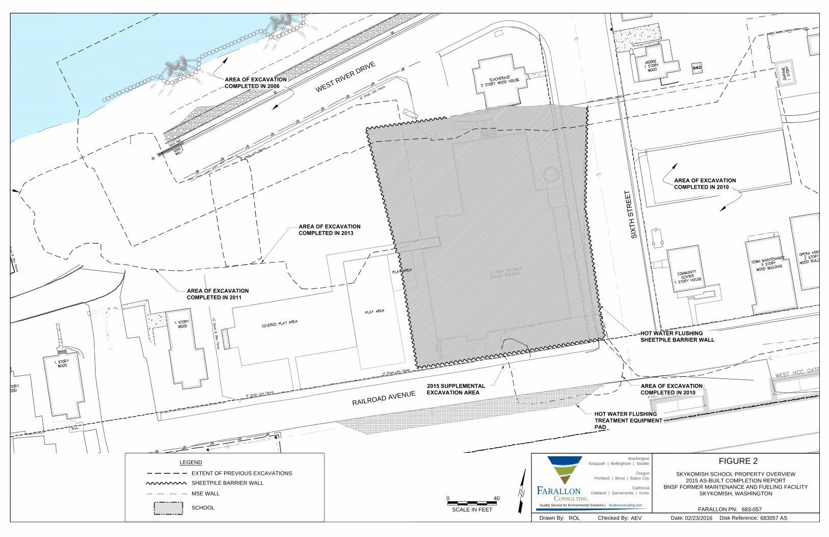
X
X
X
X
X
X
X
X
X
X
X
X
X
X
X
X
X
X
X
X
X
X
X
X
X
X
X
X
X
X
X
X
X
X
X
X
X
X
X
X
X
X
X
X
X
X
X
X
X
X
X
X
X
X
X
X
X
X
X
X
X
X
X
X
X
X
X
X
X
X
X
X
X
X
X
X
X
X
X
X
X
X
X
X
X
X
X
X
X
X
X
X
W
E
S
T
R
I
V
E
R
D
R
I
V
E
R
A
IL
R
O
A
D
A
V
E
N
U
E
AREA OF EXCAVATION
COMPLETED IN 2010
AREA OF EXCAVATION
COMPLETED IN 2011
AREA OF EXCAVATION
COMPLETED IN 2013
AREA OF EXCAVATION
COMPLETED IN 2006
LEGEND
EXTENT OF PREVIOUS EXCAVATIONS
SHEETPILE BARRIER WALL
MSE WALL
Drawn By:
ARALLONF
Disk Reference:Checked By:
FARALLON PN:
Date:
ONSULTINGC
Washington
Issaquah | Bellingham | Seattle
Oregon
Portland | Bend | Baker City
California
Oakland | Sacramento | Irvine
Quality Service for Environmental Solutions | farallonconsulting.com
FIGURE 2
SKYKOMISH SCHOOL PROPERTY OVERVIEW
2015 AS-BUILT COMPLETION REPORT
BNSF FORMER MAINTENANCE AND FUELING FACILITY
SKYKOMISH, WASHINGTON
683-057
683057 AS02/23/2016AEVROL
0
SCALE IN FEET
40
SCHOOL

A
B
S1S2S3
A'
OVBN15-AS1-2.5
OVBN15-A'S2-2.5
OVBN15-AS2-2.5
OVBN15-AS3-2.5
OVBN15-A'S3-2.5
OVBN15-BS1-2.5
OVBN15-BS2-2.5
OVBN15-BS3-2.5
EXV15-AS2-SW
Drawn By:
ARALLONF
Disk Reference:Checked By:
FARALLON PN:
Date:
ONSULTINGC
Washington
Issaquah | Bellingham | Seattle
Oregon
Portland | Bend | Baker City
California
Oakland | Sacramento | Irvine
Quality Service for Environmental Solutions | farallonconsulting.com
FIGURE 3
SUPPLEMENTAL EXCAVATION CONTOURS AND
SOIL SAMPLE LOCATIONS
2015 AS-BUILT COMPLETION REPORT
BNSF FORMER MAINTENANCE AND FUELING FACILITY
SKYKOMISH, WASHINGTON
683-057
SUPPLEMENTAL02/22/2016AEVROL
EXV15-A'S2-SW
EXV10-AS1-B
LEGEND:
2015 SUPPLEMENTAL BELOW VDL SOIL SAMPLE LOCATION
2015 SUPPLEMENTAL EXCAVATION OVERBURDEN SOIL SAMPLE LOCATION
SHEETPILE BARRIER WALL LOCATION
LIMITS OF 2010 EXCAVATION BOTTOM
A'
S1
LIMITS OF 2015 SUPPLEMENTAL EXCAVATION
2015 SUPPLEMENTAL SOIL EXCAVATION ELEVATION CONTOUR
SOIL SAMPLE GRID (PER ADDENDUM #3 TO 2010
COMPLIANCE MONITORING PLAN UPDATE

AI-1
GROUNDWATER EXTRACTION RECOVERY
SUMP AND DESIGNATION
HOT WATER INJECTION WELL AND DESIGNATION
SVE WELL AND DESIGNATION
SVE AIR INLET WELL AND DESIGNATION
GROUNDWATER MONITORING WELL AND DESIGNATION
SOIL GAS PROBE AND DESIGNATION
PHOTOIONIZATION DETECTOR AND DESIGNATION
2006 MSE WALL
SHEET PILE BARRIER WALL
GROUNDWATER AND LNAPL RECOVERY TRENCH
GROUNDWATER AND LNAPL RECOVERY TRENCH
INSTALLED TO 10'-13' BELOW GROUND SURFACE
LEGEND
U
S
T
LOCATION OF TREATMENT PIPING CORRIDOR
2%
2%
2%
Drawn By:
ARALLONF
Disk Reference:Checked By:
FARALLON PN:
Date:
ONSULTINGC
Washington
Issaquah | Bellingham | Seattle
Oregon
Portland | Bend | Baker City
California
Oakland | Sacramento | Irvine
Quality Service for Environmental Solutions | farallonconsulting.com
FIGURE 4
HOT WATER FLUSHING SYSTEM LAYOUT PLAN
2015 AS-BUILT COMPLETION REPORT
BNSF FORMER MAINTENANCE AND FUELING FACILITY
SKYKOMISH, WASHINGTON
683-057
683-038AS3/4/16AVMB
40

G:\Projects\683 BNSF\683057 Skykomish School HWF Construction\Reports\2015 As-Built Completion\683-057 2015 As-Built Completion Report.docx
TABLES
2015 AS-BUILT COMPLETION REPORT
BNSF Former Maintenance and Fueling Facility
Skykomish, Washington
Consent Decree No. 07-2-33672-9 SEA
Farallon PN: 683-057

Table 1
Overburden Soil Analytical Data
2015 As-Built Completion Report
Skykomish, Washington
Farallon PN: 683-057
OVBN15-A3 OVBN15-AS3-2.5 6/18/2015 42 4.2 29 210 11 58 252
OVBN15-AS1 OVBN15-AS1-2.5 6/18/2015 < 3.6 3.6 25 < 9.1 9.1 50 < 6.35
OVBN15-AS2 OVBN15-AS2-2.5 6/18/2015 < 3.7 3.7 26 < 9.4 9.4 52 < 6.55
OVBN15-A'S2 OVBN15-A'S2-2.5 6/18/2015 < 4.2 4.2 29 64 11 58 66.1
OVBN15-A'S3 OVBN15-A'S3-2.5 6/18/2015 < 4.1 4.1 29 < 10 10 57 < 7.05
OVBN15-BS1 OVBN15-BS1-2.5 6/18/2015 < 3.7 3.7 26 < 9.4 9.4 52 < 6.55
OVBN15-BS2 OVBN15-BS2-2.5 6/18/2015 < 3.6 3.6 25 < 9.1 9.1 50 < 6.35
OVBN15-BS3 OVBN15-BS3-2.5 6/18/2015 30 4.1 28 120 10 56 150
1,870
NOTES:
< denotes analyte not detected at or exceeding the laboratory method detection limit listed. DRO = TPH as diesel-range organics
Samples collected at 2.5 feet below ground surface. MDL = laboratory-specified method detection limit1Analyzed by Northwest Method NWTPH-Dx. MRL = laboratory-specified method reporting limit
2The total NWTPH-Dx calculation uses one-half the MDL for non-detectable concentrations to derive the sum of the DRO and ORO results ORO = TPH as oil-range organics
obtained using the NWTPH-Dx analytical method. If either the DRO or the ORO concentration was reported as a detect, then the calculated TPH = total petroleum hydrocarbons
total NWTPH-Dx concentration is indicated as a detect. If both DRO and ORO concentrations were reported as non-detects, then the
calculated total NWTPH-Dx concentration is indicated as a non-detect. Note that in some instances, data validation resulted in additional
data qualification and/or updates to laboratory data. If, for example, data validation caused an update to a non-detect result value because of
laboratory blank contamination and the data validator concluded that the result should be non-detect instead of detect, the laboratory-given
method detection limit and reporting limit were updated to match the validated non-detect result value.
3Reuse and Remediation Levels as defined in the Cleanup Action Plan for BNSF Former Maintenance and Fueling Facility, Skykomish,
Washington dated October 2007, prepared by the Washington State Department of Ecology for BNSF Railway Company.
Reuse Level for Soil3
Calculated Total
NWTPH-Dx2
(milligrams per
kilogram)Result ResultSample Location Sample Identification Sample Date
DRO (milligrams per kilogram)1
ORO (milligrams per kilogram)1
MDL MRL MDL MRL
G:\Projects\683 BNSF\683057 Skykomish School HWF Construction\Reports\2015 As-Built Completion\Tables\Tables 1 through 3
1 of 1

Table 2
Supplemental Excavation Soil Analytical Data
2015 As-Built Completion Report
Skykomish, Washington
Farallon PN: 683-057
Bottom EXV15-AS2 EXV15-AS2-BOT 6/23/2015 12 < 3.6 3.6 25 < 9.0 9.0 50 < 6.3
EXV15-AS2 EXV15-AS2-SW 6/23/2015 8 < 4.0 4.0 28 < 10 10 56 < 7
EXV15-AS2 EXV15-AS2-WW 6/23/2015 8 < 4.3 4.3 30 < 11 11 60 < 7.65
3,400
NOTES:
< denotes analyte not detected at or exceeding the laboratory method detection limit listed. DRO = total petroleum hydrocarbons (TPH) as diesel-range organics 1Depth in feet below ground surface. MDL = laboratory-specified method detection limit
2Analyzed by Northwest Method NWTPH-Dx. MRL = laboratory-specified method reporting limit
3The total NWTPH-Dx calculation uses one-half the MDL for non-detectable concentrations to derive the sum of the DRO and ORO results ORO = TPH as oil-range organics
obtained using the NWTPH-Dx analytical method. If either the DRO or the ORO concentration was reported as a detect, then the calculated
total NWTPH-Dx concentration is indicated as a detect. If both DRO and ORO concentrations were reported as non-detects, then the
calculated total NWTPH-Dx concentration is indicated as a non-detect. Note that in some instances, data validation resulted in additional
data qualification and/or updates to laboratory data. If, for example, data validation caused an update to a non-detect result value because of
laboratory blank contamination and the data validator concluded that the result should be non-detect instead of detect, the laboratory-given
method detection limit and reporting limit were updated to match the validated non-detect result value. 4Reuse and Remediation Levels as defined in the Cleanup Action Plan for BNSF Former Maintenance and Fueling Facility, Skykomish,
Washington dated October 2007, prepared by the Washington State Department of Ecology for BNSF Railway Company.
Result MDL
Sidewall
Grid Sample Location
DRO (milligrams per kilogram)2
Remediation Level for Soil4
Calculated Total
NWTPH-Dx3
(milligrams per
kilogram)Result MRL
Excavation
Area Sample Date
Sample Depth
(feet)1
Sample Identification
ORO (milligrams per kilogram)2
MDL MRL
G:\Projects\683 BNSF\683057 Skykomish School HWF Construction\Reports\2015 As-Built Completion\Tables\Tables 1 through 3
1 of 1

Table 3
Soil Stockpile Analytical Data
2015 As-Built Completion Report
Skykomish, Washington
Farallon PN: 683-057
OB-STOCK-1 OB-STOCK-1 7/13/2015 43 3.6 25 270 9.2 50 313
OB-STOCK-2 OB-STOCK-2 7/13/2015 640 3.6 25 < 9.1 9.1 50 644.55
OB-STOCK-3 OB-STOCK-3 7/13/2015 45 3.8 26 210 9.5 52 255
OB-STOCK-4 OB-STOCK-4 7/13/2015 33 3.6 25 170 9.1 50 203
OB-STOCK-5 OB-STOCK-5 7/13/2015 44 3.5 24 400 8.9 49 444
OB-STOCK-6 OB-STOCK-6 7/13/2015 27 3.6 25 91 9.1 50 118
OB-STOCK-7 OB-STOCK-7 7/13/2015 < 3.6 3.6 25 < 9.0 9.0 49 < 6.3
OB-STOCK-8 OB-STOCK-8 7/13/2015 31 3.5 25 150 8.9 49 181
OB-STOCK-9 OB-STOCK-9 7/23/2015 230 3.9 27 1,600 9.7 54 1,830
OB-STOCK-10 OB-STOCK-10 7/23/2015 < 3.7 3.7 26 140 9.4 52 141.85
OB-STOCK-11 OB-STOCK-11 7/23/2015 34 3.9 27 150 9.7 54 184
OB-STOCK-12 OB-STOCK-12 7/23/2015 < 3.8 3.8 26 94 9.6 53 95.9
OB-STOCK-13 OB-STOCK-13 7/23/2015 < 3.7 3.7 26 140 9.4 52 141.85
OB-STOCK-14 OB-STOCK-14 7/23/2015 34 3.6 25 170 9.1 50 204
OB-STOCK-15 OB-STOCK-15 7/23/2015 25 3.6 25 < 9.0 9.0 50 29.5
OB-STOCK-16 OB-STOCK-16 7/23/2015 36 3.6 25 220 9.0 50 256
OB-STOCK-17 OB-STOCK-17 9/29/2015 < 3.8 3.8 27 79 9.7 53 80.9
OB-STOCK-18 OB-STOCK-18 9/29/2015 29 4.1 28 120 10 57 149
OB-STOCK-19 OB-STOCK-19 9/29/2015 28 3.9 27 110 9.9 55 138
OB-STOCK-20 OB-STOCK-20 9/29/2015 < 3.8 3.8 26 81 9.6 53 82.9
1,870
NOTES:
< denotes analyte not detected at or exceeding the laboratory method detection limit listed. DRO = total petroleum hydrocarbon (TPH) as diesel-range organics
Samples collected at 2.5 feet below ground surface. MDL = laboratory-specified method detection limit1Analyzed by Northwest Method NWTPH-Dx. MRL = laboratory-specified method reporting limit
2The total NWTPH-Dx calculation uses one-half the MDL for non-detectable concentrations to derive the sum of the DRO and ORO results ORO = TPH as oil-range organics
obtained using the NWTPH-Dx analytical method. If either the DRO or the ORO concentration was reported as a detect, then the calculated
total NWTPH-Dx concentration is indicated as a detect. If both DRO and ORO concentrations were reported as non-detects, then the
calculated total NWTPH-Dx concentration is indicated as a non-detect. Note that in some instances, data validation resulted in additional
data qualification and/or updates to laboratory data. If, for example, data validation caused an update to a non-detect result value because
of laboratory blank contamination and the data validator concluded that the result should be non-detect instead of detect, the laboratory-given
method detection limit and reporting limit were updated to match the validated non-detect result value.
3Reuse and Remediation Levels as defined in the Cleanup Action Plan for BNSF Former Maintenance and Fueling Facility, Skykomish,
Washington dated October 2007, prepared by the Washington State Department of Ecology for BNSF Railway Company.
Reuse Level for Soil3
Sample Location Sample Identification Sample Date
Calculated Total NWTPH-
Dx2
(milligrams per kilogram)Result MRL
DRO (milligrams per kilogram)1
ORO (milligrams per kilogram)1
MDL MRL Result MDL
G:\Projects\683 BNSF\683057 Skykomish School HWF Construction\Reports\2015 As-Built Completion\Tables\Tables 1 through 3
1 of 1