Embed Size (px)
Citation preview

WPG Resources Ltd (ASX: WPG, WPGO) is pleased to advise that it has now completed its ore reserve estimate for Challenger. WPG released its mineral resource estimate for the Challenger gold mine in South Australia on 19 May 2016. Full details of the estimate and the methodology used are set out in that announcement and the resource estimate is summarised in Table 1 below.
Table 1: Challenger Mineral Resource Estimate Challenger Mineral Resource Estimate
Category Tonnage (000 t)
Grade (g/t Gold)
Contained ounces(Gold 000 oz)
Measured 147 6.98 33.5 Indicated 527 10.80 183.5 Inferred 149 11.62 55 Sub Total 823 10.27 272 Surface stockpiles Measured 122 1.30 5 Total 945 9.11 277 The total underground ore reserve estimate is 435,900 tonnes at an average grade of 5.59 g/t gold containing 78,300 ounces of gold. In addition there are ore reserves in the low grade surface stockpiles on the ROM pad. When this material is added to the underground ore reserves the total ore reserves at Challenger is 557,800 tonnes at an average grade of 4.65 g/t Au containing 83,400 ounces.
23 June 2016
ASX and Media Release
Challenger Ore Reserve Estimate

ASX Announcement – 23 June 2016 2
The Ore Reserve estimate is set out in Table 2 below, followed by a summary of material information. Detailed technical information with reference to JORC (2012) compliance for the Ore Reserve estimate is provided in Appendix 1.
Table 2: Challenger Ore Reserve Estimate as at 30 April 2016 Challenger Ore Reserve Estimate
Category Tonnage (000 t)
Grade (g/t
Gold)
Total ounces(Gold 000 oz)
Underground Ore Reserves Challenger West Proved 72.9 5.66 13.3 Probable 270.1 5.75 49.9 Total 343.0 5.73 63.2
M2 lode Proved 28.8 5.91 5.5 Probable 58.1 4.52 8.4 Total 86.9 4.98 13.9
Aminus lode Proved 1.2 3.69 0.1 Probable - - - Total 1.2 3.69 0.1
SEZ Proved - - - Probable 4.8 6.75 1.0 Total 4.8 6.75 1.0
Total Underground Ore Reserves All lodes Proved 102.9 5.71 18.9 Probable 333.0 5.55 59.4 Total 435.9 5.59 78.3
Stockpile Ore Reserves Stockpile Proved 121.9 1.30 5.1 Probable - - - Total 121.9 1.30 5.1
Total Ore Reserves Grand totals Proved 224.8 3.32 24.0 Probable 333.0 5.55 59.4 Grand Total 557.8 4.65 83.4
Totals are subject to rounding
The ore reserves and mineral resource estimates have been prepared and reported in accordance with JORC (2012) guidelines. The time datum for both estimates is 30 April 2016. The estimates have been completed by WPG since it took ownership of Challenger on 15 March 2016. The mineral resource estimate is inclusive of the ore reserves.

ASX Announcement – 23 June 2016 3
Challenger ore reserves estimated herein have been derived from measured and indicated mineral resources. The ore reserve estimate does not include any inferred mineral resources. The resource estimate for the Challenger deposit is based on the interpretation of the geology and gold bearing lode structures that has been developed as a continually evolving model by hands-on experienced site geologists before and since the commencement of underground mining in 2002, and a combination of drilling results, face sampling and geological mapping of development headings. The resource was estimated using a combination of geological grade calculations, generic modelling and block modelling. The cut-off grade used in the resource estimate was 5.0 g/t Au for all of the lodes and is based on what is considered an economic cut-off for underground mining in relation to the prevailing gold price and projected operating costs. The Ore Reserve was estimated by comparing resource data to the grade control estimates of the April 2016 mineral resource estimate to determine the validity of the resource for conversion to reserve. Detailed technical information with reference to JORC (2012) compliance for the mineral resource estimate was included in WPG’s ASX announcement of 19 May 2016 and is included in JORC Table 1 Sections 1 to 3 in Appendix 1. WPG confirms that it is not aware of any new information or data that materially affects the information included in the 19 May 2016 market announcement and above in relation to the mineral resource estimate, and confirms that to the best of its knowledge and belief all material assumptions and technical parameters underpinning the mineral resource estimates in the 19 May 2016 market announcement continue to apply and have not materially changed. JORC Table 1 Section 4 for the ore reserve estimate is provided in Appendix 1. Summary of Material Information and Modifying Factors Mining and processing operations at Challenger have been conducted since 2001. Although there was a temporary suspension of operations from 15 March 2016 to early May 2016 when operations recommenced under WPG’s management, Challenger is a mature operation with reliable historical data. Inputs for the ore reserve estimate are generally consistent with recent and planned operating practices and experience. For this reason the mineral resource and ore reserve estimation methodologies are considered to be at a higher level than would normally be found in a feasibility study for a greenfield project. The Challenger resource models were used to create detailed life of mine (LOM) designs for the extraction of each resource lode. The design was based around an uphole retreat, top down stoping sequence. This mining technique has been used in the past, and will be used in the future. The existing Challenger CIP and gravity processing facility will be utilised to extract the gold. The performance of this plant is well understood.
ASX Announcement – 23 June 2016 4
Mining of the narrow vein Challenger lodes has been designed with a minimum mining width of 1.5m. Based on historical mining at Challenger an external dilution of 40% has been applied in the calculation of all reserves, unless the development has been completed and a full stope analysis has been produced indicating variations to this dilution based on geotechnical input. A specific stope extraction factor has been applied to each level in the reserve estimation, based on the geological resource model, geotechnical requirements and the extraction sequence of each orebody shoot. Each lode at Challenger has been assessed individually against the targeted production parameters, the historical and current site operating costs along with the modifying factors that have been applied to determine the economic viability and justification for conversion to reserve. The resource tonnes and grade of each level has been analysed individually using site and contractor fixed costs, the contracted schedule of rates against the level physicals, forecast metallurgical recovery based on historical processing plant performance and a set gold price based on corporate guidance. The use of a generic geological resource model for Challenger West and the partial completion of the M2 remnant stopes have required each level to be evaluated individually. The resource used for the reserve estimation has a 5.0g/t Au lower cut-off applied for underground workings. The key modifying factors of 40% mining dilution, specific level extraction factors not greater than 90% for anything other than designed remnant material and 95% milling recovery are consistent with historical performance of the areas and lodes contained in the reserve. Projected capital costs are based on historical actuals and assessment of the required activities to support the new mine plan by on site management. Other modifying factors include a long term gold price assumption of A$1,550 per ounce that has been used for the ore reserve estimate. This is a conservative assumption under current market conditions. Operating costs have been based on budgeted fixed costs and variable costs under re-negotiated service provider contracts including the key new mining contractor rates and LOM physicals. Included in these costs are:
• A$3.00/oz transport, treatment and refining costs based on historical actuals and new site contracts;
• Total royalties of A$54.00/oz of gold produced were adopted in the reserve calculation; and
• A silver credit of A$2.10/oz of gold produced that is based on historical production reconciliations.
ASX Announcement – 23 June 2016 5
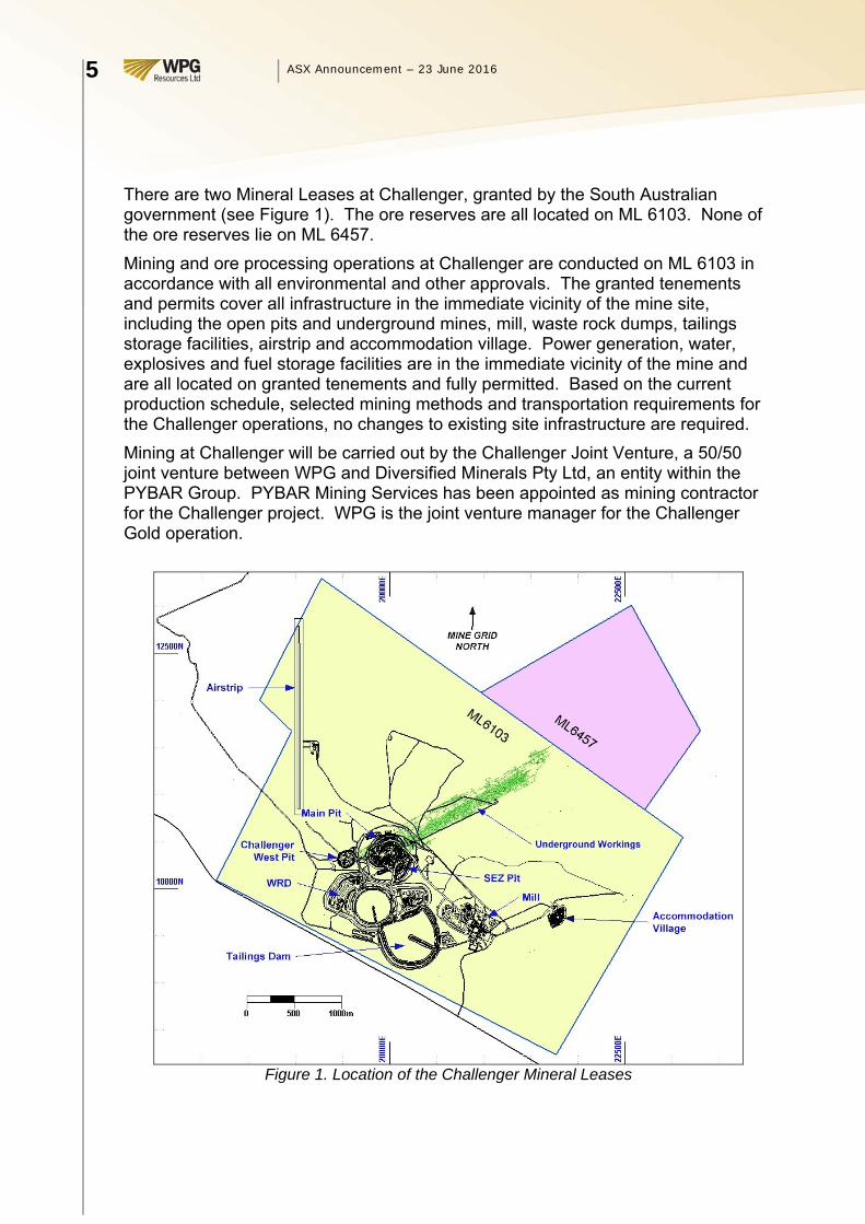
There are two Mineral Leases at Challenger, granted by the South Australian government (see Figure 1). The ore reserves are all located on ML 6103. None of the ore reserves lie on ML 6457. Mining and ore processing operations at Challenger are conducted on ML 6103 in accordance with all environmental and other approvals. The granted tenements and permits cover all infrastructure in the immediate vicinity of the mine site, including the open pits and underground mines, mill, waste rock dumps, tailings storage facilities, airstrip and accommodation village. Power generation, water, explosives and fuel storage facilities are in the immediate vicinity of the mine and are all located on granted tenements and fully permitted. Based on the current production schedule, selected mining methods and transportation requirements for the Challenger operations, no changes to existing site infrastructure are required. Mining at Challenger will be carried out by the Challenger Joint Venture, a 50/50 joint venture between WPG and Diversified Minerals Pty Ltd, an entity within the PYBAR Group. PYBAR Mining Services has been appointed as mining contractor for the Challenger project. WPG is the joint venture manager for the Challenger Gold operation.
Figure 1. Location of the Challenger Mineral Leases

ASX Announcement – 23 June 2016 6
Relevant environmental and other approvals for Challenger include:
• There are no identified naturally occurring risks that are likely to impact on the Challenger operation;
• A Native Title Mining Agreement has been in place with the Antakirinja Matu–Yankunytjatjara Aboriginal Corporation (AMYAC) since 2002;
• A pastoral agreement which covers road access with the Jumbuck pastoral property;
• A deed of access for operation within the WPA is in place with the Department of Defence; and
• Site rehabilitation in accordance with the project’s Program for Environmental Protection and Rehabilitation.
Further Information For further information please contact WPG’s Managing Director & CEO, Martin Jacobsen or CFO, Wayne Rossiter on (02) 9251 1044. Competent Person Statements Mineral Resources The information that relates to Mineral Resources contained in this report is based on, and fairly represents, information and supporting documentation prepared by Mr Stuart Hampton. Stuart Hampton is a Member of the Australasian Institute of Mining and Metallurgy. He is an independent consultant geologist who previously compiled information concerning the Exploration Results, Mineral Resources and Ore Reserve estimates for the Challenger gold mine and worked at Challenger for 11 years. He qualifies as a Competent Person as defined in the December 2012 edition of the Australasian Code for Reporting of Exploration Results, Mineral Resources and Ore Reserves (the JORC Code) and has sufficient experience relevant to the style of mineralisation being reported herein. Stuart Hampton has consented in writing to the inclusion in this report of the matters based on his information in the form and context in which it appears. Ore Reserves The information that relates to Ore Reserves contained in this report is based on, and fairly represents, information and supporting documentation prepared by Mr Luke Phelps.

ASX Announcement – 23 June 2016 7
Luke Phelps is a Member of the Australasian Institute of Mining and Metallurgy. He is a full time employee of Challenger Gold Operations Pty Ltd, a wholly owned subsidiary of WPG Resources Ltd, who previously compiled information concerning the Ore Reserve estimates for the Challenger gold mine and has worked at Challenger for over 6 years. He qualifies as a Competent Person as defined in the December 2012 edition of the Australasian Code for Reporting of Exploration Results, Mineral Resources and Ore Reserves (the JORC Code) and has sufficient experience relevant to the style of mineralisation being reported herein. Luke Phelps has consented in writing to the inclusion in this report of the matters based on his information in the form and context in which it appears. Forward-Looking Statements
This document may include forward-looking statements. Forward-looking statements include, but are not limited to statements concerning WPG’s planned mining and exploration programs and other statements that are not historical facts. When used in this document, the words such as “could”, “plan”, “estimate”, “expect”, “intend”, “may”, “potential”, “should” and similar expressions are forward-looking statements. In addition, summaries of Exploration Results and estimates of Mineral Resources and Ore Reserves could also be forward looking statements. Although WPG believes that its expectations reflected in these forward-looking statements are reasonable, such statements involve risks and uncertainties and no assurance can be given that actual results will be consistent with these forward-looking statements.
WPG Resources Ltd – ASX Announcement – 23 June 2016
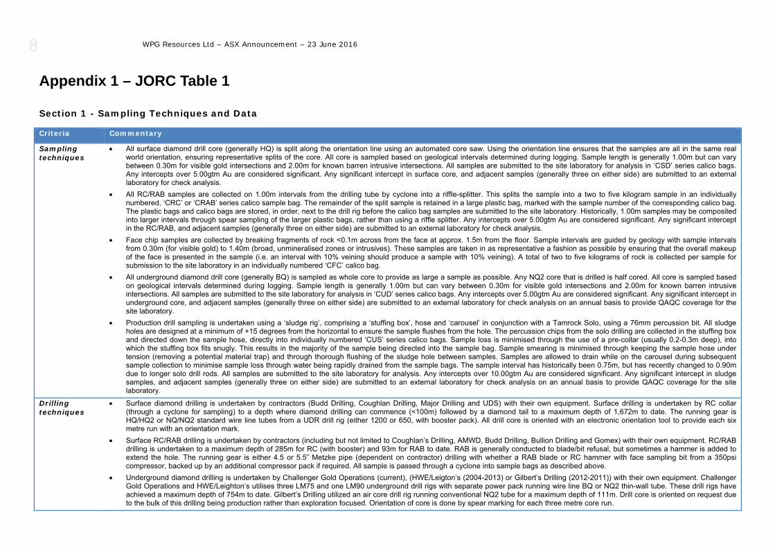
Appendix 1 – JORC Table 1 Section 1 - Sampling Techniques and Data Criteria Commentary
Sampling techniques
• All surface diamond drill core (generally HQ) is split along the orientation line using an automated core saw. Using the orientation line ensures that the samples are all in the same real world orientation, ensuring representative splits of the core. All core is sampled based on geological intervals determined during logging. Sample length is generally 1.00m but can vary between 0.30m for visible gold intersections and 2.00m for known barren intrusive intersections. All samples are submitted to the site laboratory for analysis in ‘CSD’ series calico bags. Any intercepts over 5.00gtm Au are considered significant. Any significant intercept in surface core, and adjacent samples (generally three on either side) are submitted to an external laboratory for check analysis.
• All RC/RAB samples are collected on 1.00m intervals from the drilling tube by cyclone into a riffle-splitter. This splits the sample into a two to five kilogram sample in an individually numbered, ‘CRC’ or ‘CRAB’ series calico sample bag. The remainder of the split sample is retained in a large plastic bag, marked with the sample number of the corresponding calico bag. The plastic bags and calico bags are stored, in order, next to the drill rig before the calico bag samples are submitted to the site laboratory. Historically, 1.00m samples may be composited into larger intervals through spear sampling of the larger plastic bags, rather than using a riffle splitter. Any intercepts over 5.00gtm Au are considered significant. Any significant intercept in the RC/RAB, and adjacent samples (generally three on either side) are submitted to an external laboratory for check analysis.
• Face chip samples are collected by breaking fragments of rock <0.1m across from the face at approx. 1.5m from the floor. Sample intervals are guided by geology with sample intervals from 0.30m (for visible gold) to 1.40m (broad, unmineralised zones or intrusives). These samples are taken in as representative a fashion as possible by ensuring that the overall makeup of the face is presented in the sample (i.e. an interval with 10% veining should produce a sample with 10% veining). A total of two to five kilograms of rock is collected per sample for submission to the site laboratory in an individually numbered ‘CFC’ calico bag.
• All underground diamond drill core (generally BQ) is sampled as whole core to provide as large a sample as possible. Any NQ2 core that is drilled is half cored. All core is sampled based on geological intervals determined during logging. Sample length is generally 1.00m but can vary between 0.30m for visible gold intersections and 2.00m for known barren intrusive intersections. All samples are submitted to the site laboratory for analysis in ‘CUD’ series calico bags. Any intercepts over 5.00gtm Au are considered significant. Any significant intercept in underground core, and adjacent samples (generally three on either side) are submitted to an external laboratory for check analysis on an annual basis to provide QAQC coverage for the site laboratory.
• Production drill sampling is undertaken using a ‘sludge rig’, comprising a ‘stuffing box’, hose and ‘carousel’ in conjunction with a Tamrock Solo, using a 76mm percussion bit. All sludge holes are designed at a minimum of +15 degrees from the horizontal to ensure the sample flushes from the hole. The percussion chips from the solo drilling are collected in the stuffing box and directed down the sample hose, directly into individually numbered ‘CUS’ series calico bags. Sample loss is minimised through the use of a pre-collar (usually 0.2-0.3m deep), into which the stuffing box fits snugly. This results in the majority of the sample being directed into the sample bag. Sample smearing is minimised through keeping the sample hose under tension (removing a potential material trap) and through thorough flushing of the sludge hole between samples. Samples are allowed to drain while on the carousel during subsequent sample collection to minimise sample loss through water being rapidly drained from the sample bags. The sample interval has historically been 0.75m, but has recently changed to 0.90m due to longer solo drill rods. All samples are submitted to the site laboratory for analysis. Any intercepts over 10.00gtm Au are considered significant. Any significant intercept in sludge samples, and adjacent samples (generally three on either side) are submitted to an external laboratory for check analysis on an annual basis to provide QAQC coverage for the site laboratory.
Drilling techniques
• Surface diamond drilling is undertaken by contractors (Budd Drilling, Coughlan Drilling, Major Drilling and UDS) with their own equipment. Surface drilling is undertaken by RC collar (through a cyclone for sampling) to a depth where diamond drilling can commence (<100m) followed by a diamond tail to a maximum depth of 1,672m to date. The running gear is HQ/HQ2 or NQ/NQ2 standard wire line tubes from a UDR drill rig (either 1200 or 650, with booster pack). All drill core is oriented with an electronic orientation tool to provide each six metre run with an orientation mark.
• Surface RC/RAB drilling is undertaken by contractors (including but not limited to Coughlan’s Drilling, AMWD, Budd Drilling, Bullion Drilling and Gomex) with their own equipment. RC/RAB drilling is undertaken to a maximum depth of 285m for RC (with booster) and 93m for RAB to date. RAB is generally conducted to blade/bit refusal, but sometimes a hammer is added to extend the hole. The running gear is either 4.5 or 5.5” Metzke pipe (dependent on contractor) drilling with whether a RAB blade or RC hammer with face sampling bit from a 350psi compressor, backed up by an additional compressor pack if required. All sample is passed through a cyclone into sample bags as described above.
• Underground diamond drilling is undertaken by Challenger Gold Operations (current), (HWE/Leigton’s (2004-2013) or Gilbert’s Drilling (2012-2011)) with their own equipment. Challenger Gold Operations and HWE/Leighton’s utilises three LM75 and one LM90 underground drill rigs with separate power pack running wire line BQ or NQ2 thin-wall tube. These drill rigs have achieved a maximum depth of 754m to date. Gilbert’s Drilling utilized an air core drill rig running conventional NQ2 tube for a maximum depth of 111m. Drill core is oriented on request due to the bulk of this drilling being production rather than exploration focused. Orientation of core is done by spear marking for each three metre core run.

WPG Resources Ltd – ASX Announcement – 23 June 2016
Criteria Commentary
• Sludge drilling is undertaken using a Sandvik Solo DL31-7C drill rig with a 64mm percussion bit in an open hole. This open hole is capped by the stuffing box of the sludge rig, allowing for sample collection.
Drill sample recovery
• All drill core is presented as whole core in core trays by the contractor. Core loss is noted by the diamond driller on an additional core block if required. This core is assembled and marked up using core blocks inserted at the end of every run. Any loss of core is discussed with the drilling contractor in a process of constant improvement to maximise returns. In the case of core loss, generally only fine material is lost through grinding. Unless a mineralised leucosome is ground away, there is no sample bias due to fines loss. Any discrepancies between the measured length of the core and that of the core blocks are identified and recorded in logging as gaps in the lithology and also in the geotechnical logging.
• Surface RC and RAB samples are all passed though cyclones to maximise sample return. There is a known loss of very fine material from the cyclone when conditions are dry and the possibility for sample cross-contamination when sample condition are wet. This sample loss is systematic and is taken into consideration when comparing this data to that of other drilling types. There is no established relationship between fines loss and grade bias.
• Sludge sample return is reliant on effective seals in the sludge rig to ensure good return and adequate flushing of the drill hole between samples to reduce smearing to a minimum. Sample loss will result in a light sample. 100% sample return will result in a sample that is 9.25kg in weight (for a 75cm sample), typically samples returned from sludging weigh in the order of 8.00kg (for a 75cm sample) showing a sample loss of ~13%. This loss is due to washing out of fines from the sample bag both during collection and during draining. This sample loss is systematic and is taken into consideration when comparing this data to that of other drilling types. There is no established relationship between fines loss and grade bias.
Logging • All drill core (100%) is geologically (lithology, mineralisation, structure) and geotechnically (Q-system) logged down to cm-scale (for fine structures). Any leucosome greater than 0.20m in length is recorded as a separate lithology. The logging is quantitative in nature as lithology percentages and compositions are recorded and all geotechnical logging relies on measurements for calculation of Q. All drill core is digitally photographed, one core tray (approx. eight metres of core) per photo, with the photos kept on the site server for reference.
• All RC/RAB samples (100%) have a portion washed and placed into a chip tray for logging. This logging comprises qualitative geological records (lithology and mineralisation) on a sample scale (generally 1.00m samples). Chip trays are retained for reference, as a result photographs are not taken.
• Face chips are logged through either a face map and/or digital photograph of the face. Qualitative geology (dm-scale) is recorded on the face sheet and the face photographs are stored on the site server for reference. >98% of faces sampled will have face maps/photographs, the remainder are absent due to camera malfunction.
• All Sludge samples (100%) have a portion washed and placed into a chip tray for logging. This logging comprises qualitative geological records (lithology and mineralisation) on a sample scale (generally 0.75-0.90m samples). As sludge drilling is done as a part of the production cycle, the chips are retained for a maximum of six months (the maximum ‘life cycle’ of any particular stope block) before being discarded. No photographs are retained of the sludge chips.
Sub-sampling techniques and sample preparation
• Surface diamond drill core is cut in half, lengthways along the orientation line, by an automatic core saw. One half of the core is submitted to the site laboratory for analysis, the other half is retained in core trays that are marked with the hole id and tray number. If any re-analysis from original sample is required, the core is cut again (at right angles to the orientation line), producing quarter core for re-analysis.
• Surface RC/RAB samples are either (currently) riffle split from the rig cyclone into sample bags and retention samples or (historically) sampled by spear into either 1.00m or 2.00m composite samples. These sub-samples are submitted to the site laboratory for analysis. Due to their small fragment size, crushing is not required. If re-analysis from original sample is required, the larger retention sample is then riffle split to produce another sub-sample.
• All face chip samples are sampled to be as representative as possible of the source material and are entirely processed by the site laboratory. If any re-analysis is required, the reject sample (see below) is riffle split to produce another PAL sample.
• Underground diamond drill core is sampled as whole core, due to its use for production purposes. The sample is submitted to the site laboratory for analysis. If any re-analysis is required, the reject sample (see below) is riffle split to produce another PAL sample.
• Sludge samples are submitted as entire samples to the site laboratory, in the calico bags they were collected in. Due to their small fragment size, crushing is not required. If any re-analysis is required, the reject sample (see below) is riffle split to produce another PAL sample.
• All samples submitted to the site laboratory are processed in the same way. The samples are dried at a maximum of 90 degrees Celsius to drive off moisture that would interfere with splitting. After drying, the samples are crushed (if required) in a Boyd Crusher to approximately 4mm in size and then split through a rotary sample splitter to produce a sub-sample. The crusher is cleaned regularly, and in the case of exploration samples it has barren material (bricks) crushed through it to ensure no smearing prior to the sample run being crushed. Each reject is retained for resampling (re-splitting) if needed and each sub-sample (400 - 600g) is stored in individual, numbered plastic containers for analysis.
• Each sample can be tracked by its sample number through the entire laboratory process and results for the original samples and all QAQC samples are presented in digital form to the Geologists.
Quality of assay data and laboratory
• Assaying on site is completed using the PAL (pulverising aggressive leach) process. This process effectively replicates the process in the site mill. Each sample is pulverised in aqueous solution with cyanide bearing assay tabs and a collection of assorted sized ball bearings. Each sample is processed in this way for an hour, resulting in a Au-CN complex bearing liquor and remnant pulverised sample. The pulverised material is 95% passing 75 microns, being the ideal liberation size for gold at Challenger.
• All samples submitted to the site laboratory are clayey regolith (near surface), gneiss or an intrusive (mafic or lamprophyre). In the case of clayey and exploration samples, a blank sample

WPG Resources Ltd – ASX Announcement – 23 June 2016
Criteria Commentary
tests run is conducted between sample jobs to ensure no smearing and that all of the clayey material is removed from the PAL. • Every twentieth sample is duplicated for the original sample bag (re-split) to produce a duplicate. Every sample run (53 samples) will contain at least two duplicates, a blank and a standard
(prepared by Gannet Holdings Pty Ltd). These are to ensure that the sub-sampling is representative, that the PAL is correctly cleaned between sample runs and that the PAL is pulverising the samples correctly for full gold extraction.
• Following PAL processing, the samples are individually decanted, centrifuged and prepared for analysis in an AAS by solvent separation using DIBK (20 minutes). The sample is then aspirated through the AAS to produce a reading. The AAS is calibrated for each sample run using analytical reagent prepared standards (of 1.0, 5.0, 10.0 and 20.0 g/t Au) from Rowe Scientific. Each sample is adjusted for sample weight in Labman software to produce the gold grade in ppm. These grades are presented to site Geologists in MS Excel .csv spread sheets.
• For each sample job; blanks, standards and duplicates are examined to ensure that the blanks are below detection (0.01ppm), the standards are within 8% (experimental accuracy) and that the duplicates are ‘reasonable’ with respect to the nugget effect of the Challenger deposit. Any sample jobs that fail these checks will be re-analysed from re-splits of the original samples. In addition, all the blanks, standards and duplicates are examined quarterly to ensure that the laboratory is maintaining overall operating standards.
Verification of sampling and assaying
• Any significant intercepts in exploration drilling and selected significant intercepts from underground production diamond and sludge drilling are submitted to Genalysis at least annually for external analysis. This analysis is undertaken by SP-02 or SP-03 sample preparation followed by partial fire assay using a 50 gram charge (FA50). These results are compared to the original PAL results to ensure that the site analyses are repeatable. While the two analysis processes are different, a correlation 0.96 has been achieved for the last comparison, undertaken in September 2015, and 0.83 to 0.98 over the last two years.
• Challenger Gold Mine does not use twinned holes due to time and budgetary constraints, however, production grades based on site sampling have, over the life of the mine, reconciled to within 5% of the predicted grade. Indicating that the sampling regime on site is producing data that is representative of the material produced from the mine.
• Face sampling is recorded on face sheets, retained on site for reference. This information is entered daily to the site server through a standard form, ensuring that the correct information is recorded and consistent. Core, RC/RAB and Sludge logging is undertaken directly onto standard logging forms on laptop PCs. The forms for these logs have in-built filters to ensure that the correct logging codes are used. These logs are stored on the site server, which is backed up daily. All sample information is recorded both in the relevant logs/face sheets and in sample submission forms that are submitted to the laboratory (on and off site). This allows checking that all samples are present and accounted for by laboratory staff. Assay results are generated as MS Excel .csv files that are stored on the site server and are manually merged with the primary logging/face sheet information. This merged data (logs, collar information and assays) are all imported to the site Diamond Drilling Database in MS Access for use in Surpac. All information imported to the database is checked by the importer in MS Access and Surpac to ensure the correct location/display of data. Ongoing checks are carried out by the entire technical team as the data is used.
• The only modification of assay data, following creation by Labman software is altering of results below detection, <0.01g/t Au, to 0.001g/t Au, averaging of duplicate results to produce an ‘au_plot’ grade for plotting and application of c80, c140 and c180 cut-offs to the primary data. All of these modifications are undertaken using the merged data in MS Excel (using standard forms), prior to importing to MS Access
Location of data points
• All surveys on site are carried out by qualified Surveyors using a Total Station Leica theodolite from known wall stations determined from surface stations located by GPS. Surveying in this manner provides three dimensional collar co-ordinates and development pickups to mm-scale accuracy. Drill hole collars are surveyed in the same way as the rest of the workings with collar dip and azimuth determined by surveying a rod that fits into the drill holes. The collar surveys are transmitted electronically to the site Geologists who merge this information into the MS Excel logs for each drill hole. All sludge and RC/RAB drill holes are assumed to be straight due to their short length. On site surveying of sludge holes (using diamond drill electronic Eastman cameras) have shown that while the sludge holes do experience minor clockwise deviation, the overall effect on the hole is negligible. Down hole surveying of diamond drill core (surface and underground) is undertaken with a single-shot electric down hole compass/camera at a minimum of every 30m down hole, although multi-shot and gyroscope units have been trialled in surface diamond drill holes.
• Face locations are determined by the site Geologists using development pickups and measured distances for each face from known survey stations. These figures are merged with the face information (geology/assays) in MS Excel prior to importing the data into MS Access.
• All stope voids are surveyed by an OPTEC V400/533 cavity monitoring system (CMS) in conjunction with the theodolite. The resultant CMS files are merged in Surpac to produce single stope voids.
• All survey data is stored as local Challenger Mine Grid. Challenger Mine Reduced Level (RL) = AHD + 1000m so AHD 193m level = 1193mRL. Transformations between AMG and local grids: origin, azimuth AMG origin and azimuth conversions are based on the following coinciding points.

WPG Resources Ltd – ASX Announcement – 23 June 2016
Criteria Commentary
AMG Co-ordinates Challenger Mine Grid Station Name mN mE mAHD mN mE mRL
CH10 6693784.890 363338.265 194.977 10524.890 19860.005 1194.977 CH20 6693917.900 363657.477 50.069 10499.951 20204.989 1050.069 Origin 6693379.301 363699.494 194.410 10000.000 20000.000 1194.410
Flat Battery 6693411.735 363510.463 194.314 10114.083 19845.777 1194.314 Challenger Mine Grid North 0° = 329.0° MAGNETIC Challenger Mine Grid North 0° = 333° 14’41”AMG (grid bearing + 26°45’19” = AMG bearing) Challenger Mine Grid 31° = Magnetic North 0° • Topographic control is taken from the surface stations (above) and traversed to the operating areas through the use of wall stations. The underground surveying was calibrated by gyro-
survey in 2008.
Data spacing and distribution
• Surface drill hole data (both exploration and production) is designed to provide a 12.5 to 25 metre hole separation on section, as perpendicular to the ore body as possible. Historically surface exploration drilling has been undertaken on 125m sections, at right angle to the plunge of the ore body. NAVI drilling has been undertaken to drill vertical fans of holes at the required spacing.
• Underground drilling is drilled at either 20m horizontal or from 20 to 100m vertically spaced fans. Holes are designed to intersect the lodes at 15 to 25m spacing along strike, as close to perpendicular to the strike of the lodes with fold closures specifically targeted. Underground and surface drilling is adequate to broadly define the lodes for the purposes of level planning.
• Face sampling is undertaken for every (practical) face in mineralised development, and as required elsewhere. This results in face and wall information every 3 to 4 metres along all of the ore drives.
• Sludge drilling is undertaken at five to ten metre ring spacing, at right angles to the plunge/strike of the lodes (145/325 degrees azimuth, mine grid) acting as an infill pattern between development and diamond drilling. Sludge spacing down dip can vary from five to fifteen metres as required to prove continuity and structural behaviour of the lodes.
• Data spacing is critical in the Challenger deposit, with higher data density provided from face and sludge drilling providing the coverage required to fully model this structurally complex deposit. For areas with less data density (i.e. diamond drilling only), modelling from more data dense areas is projected into the less dense areas using the data available.
• Resource data is composited by geological modelling to inform either a length weighted grade model (e.g. in the case of M1 or M2) or to inform a block model (e.g. in the case of Challenger West where 0.5m composites were used).
Orientation of data in relation to geological structure
• The orientation of any sampling (face, sludge, RC/RAB or core) are designed to be as perpendicular to the lode system as possible. The only instance where this is not possible is in the instance of sludge drilling where the only drilling platform is the ore drive. In this instance, drilling is designed to pass through structure at as low an angle as possible but these still result in drill holes that pass along the structure, often resulting in a very high grade drill hole representing a (possibly) quite narrow feature. During any grade calculation (be it production or resource) these structure parallel drill holes are examined for their effect on the final grade result, and where appropriate, excluded from the grade calculations, thus reducing the effect of any sample bias.
Sample security
• Samples are submitted to the laboratory as soon as practical after sampling in individually numbered calico sample bags. The numbers series on the bags (e.g. CUS, CUD, CFC etc.) tell laboratory staff what the sample type is and how long it is likely to take to dry for processing. Analysis is not undertaken until all descriptive paperwork is correctly submitted for the samples. From acceptance of the samples, each sample is tracked on site through Labman software to ensure that each assay is correctly matched with its sample. Any discrepancy between submitted samples and the paperwork is identified and may result in the entire sample job being resampled form original material prior to analysis. External laboratories utilise their own systems for sample tracking.
Audits or reviews
• Data reviews are undertaken on an ongoing basis by site Geologists while using the data. Any errors identified (either by staff, MS Access or Surpac) is queried and corrected as a part of a program of continual improvement.
• Sampling reviews have been undertaken through both duplicate sampling of original materials (faces, core etc.) and through comparison of sample types (e.g. diamond compared to sludge, sludge compared to faces). The result of these reviews have consistently returned results that, while highlighting the high nugget effect, are consistent between both repeats and sample types.
• Lab audits are done annually, showing that operating procedures for sample management, QAQC and result consistency are being adhered to.

WPG Resources Ltd – ASX Announcement – 23 June 2016
Section 2 – Reporting of Exploration Results
Criteria Commentary
Mineral tenement and land tenure status
• All exploration referred to in the Challenger portion of the 2014-15 Annual Report was undertaken at the Challenger Gold Mine on EL 4468 ‘Jumbuck’. This Exploration Lease comprises 687 square kilometres within the Woomera Prohibited Zone, straddling the Mobella and Commonwealth Hill pastoral blocks. In addition, this exploration was undertaken within the current Challenger Mine Lease ML 6103.
Exploration done by other parties
• All exploration undertaken during the reporting period was undertaken by Challenger Gold Operations
Geology • Challenger occurs within the Mulgathing Complex of the Gawler Craton and the area is characterized by Archaean to mid-Proterozoic gneissic country rock. Original granulite facies metamorphism is overlaid by retrograde amphibolite facies recrystallization around 1650 - 1540 Ma (Tomkins, 2002). Saprolitic clays extended to 50 m depth within the ore zone, reflecting a deeper base of oxidation.
• High-grade gold mineralisation is associated with coarse-grained quartz veins with feldspar, cordierite and sulphides dominated by arsenopyrite, pyrrhotite and lesser telluride. These veins are interpreted as migmatites that have undergone partial melting, with this melting reflecting a precursor hydrothermal alteration event (McFarlane, Mavrogenes and Tomkins, 2007).
Three main types of leucosome/vein styles have been defined: 1. quartz dominant veins, which may be remnant premetamorphic mineralised veins 2. polysilicate veins, which are dominant in the main ore zones and host the majority of the mineralisation 3. pegmatitic veins, which are unmineralised, late stage, with cross-cutting relationships.
• The gold mineralisation is structurally controlled through emplacement of the partial melt into relatively low-strain positions. McFarlane, Mavrogenes and Tomkins (2007), using Monazite geochronology proposed a 40 Ma period between 2460 and 2420 Ma of repeated high-temperature events.
• The Challenger Structure can be defined as a laterally extensive shear zone with shoots that plunge 30° to 029° (AMG). These ore shoots are defined by leucosome veins, which are characteristically ptygmatically folded. The small-scale folding is parasitic to the overall larger scale folding that can be interpreted from drill core. The folding is interpreted as prepeak metamorphism along with gold mineralisation. Post-folding, the Challenger shoots were subjected to extreme WNW-ESE shortening and extension directed shallowly to the NE.
Reference: Androvic, P, Bamford, P, Curtis, J, Derwent, K, Giles, A, Gobert, R, Hampton, S, Heydari, M, Kopeap, P and Sperring, P, 2013. Challenger Gold Mine, Australasian Mining and Metallurgical Operating Practices, AusIMM. 1097-1112.
Drill hole Information
• Please refer to Table 1, below.
Data aggregation methods
• For all results at Challenger Gold Mine, a low cut-off of 0.01g/t Au is applied (limit of detection), these results are replaced with 0.001g/t Au in the drilling database to flag that they are below detection. Assay data is stored as uncut, au_plot (the first assay where duplicates were completed), c80, c140 and c180 for integration with the site database. No upper grade truncation is used for significant intercepts.
The method to be used for calculating all significant intercepts (sig ints) is as follows: 1. All sig ints must grade >5g/t. The only exception to this rule is where you wish to highlight a significant, but lower grade exploration intersection in one of our peripheral lodes such as
in Aminus, OFW or Challenger West 2. All sig ints should include all adjacent ore grade material (≥1.00g/t) as long as this material does not drop the intersection below 5g/t. 3. Intersections should be amalgamated together as long as there are no more than two intervening waste assays and where the amalgamation does not drop the total grade below 5g/t. 4. Step 2 and 3 should be repeated until there is no further change. • No metal equivalents are used in exploration reporting due to exploration being solely for gold. Trace silver is known but is not factored into contained metal.
Relationship between mineralisation widths and
• All mineralisation widths are reported as depths down hole as all exploration drilling is designed to be as perpendicular to the lodes as possible. As this exploration is entirely for resource development, any significant intercepts used in lode modelling are constrained by the resulting model, producing a de-facto true width for further calculations.

WPG Resources Ltd – ASX Announcement – 23 June 2016
Criteria Commentary
intercept lengths Diagrams • No significant discovery is being reported. All exploration drilling was undertaken on expected mineralised areas of the Challenger and associated deposits to upgrade the resource
estimate.
Balanced reporting
• As these exploration holes are drilled to infill (on various scales) previous drilling, as a result any results/modelling based on these results are balanced by existing drilling.
Other substantive exploration data
• No other meaningful or material exploration has been undertaken.
Further work • Planned exploration for the next financial year focuses on infilling the generic Challenger West resource and the 'Challenger Deeps' to extend the mine life Table 1 - Challenger Exploration Drill hole information
Exploration Diamond Drill hole Details Intercept Details
Hole ID Collar mN Collar mE Collar mAHD Hole Length From (m) To (m) Interval (m) Au (g/t) Shoot Midpoint (mRL)
15CUD1662 6,695,006.858 364,466.651 -774.893 239.61 215.15m 217.00m 1.85m @ 205.21g/t CW 170mRL 15CUD1673 6,693,458.627 363,205.362 -39.068 103.57 57.00m 58.00m 1.00m @ 20.18g/t CSSW 939mRL 15CUD1679 6,693,458.635 363,205.473 -38.539 134.18 85.00m 86.00m 1.00m @ 17.12g/t CSSW 951mRL 15CUD1683 6,693,458.759 363,207.342 -39.248 119.41 32.00m 33.00m 1.00m @ 15.59g/t CSSW 950mRL 15CUD1683 6,693,458.759 363,207.342 -39.248 119.41 67.00m 68.00m 1.00m @ 17.35g/t CSSW 937mRL 15CUD1684 6,694,763.954 364,063.767 -548.233 299.66 176.00m 176.75m 0.75m @ 115.55g/t CW 383mRL 15CUD1705 6,694,778.020 364,123.691 -557.793 150.00 114.27m 114.57m 0.30m @ 145.51g/t CW 411mRL 15CUD1708 6,694,777.748 364,123.841 -557.316 194.18 149.71m 150.67m 0.96m @ 79.48g/t CW 431mRL 15CUD1714 6,694,778.276 364,123.174 -557.302 155.53 63.00m 64.00m 1.00m @ 19.50g/t CW 437mRL 15CUD1717 6,693,458.412 363,204.758 -38.258 166.53 54.60m 54.90m 0.30m @ 21.31g/t CSSW 962mRL 15CUD1718 6,693,458.530 363,205.098 -38.206 152.00 115.00m 116.00m 1.00m @ 18.92g/t CSSW 965mRL 15CUD1724 6,693,755.310 363,466.087 -112.323 283.30 100.15m 100.45m 0.30m @ 23.32g/t CSSW 843mRL 15CUD1724 6,693,755.310 363,466.087 -112.323 283.30 138.00m 140.67m 2.67m @ 11.35g/t CSSW 826mRL 15CUD1727 6,694,781.542 364,124.719 -558.947 86.52 65.00m 67.00m 2.00m @ 16.33g/t CW 389mRL 15CUD1730 6,694,778.491 364,123.613 -558.475 119.67 88.11m 88.52m 0.41m @ 119.53g/t CW 393mRL 15CUD1749 6,694,861.562 364,173.913 -665.643 100.68 39.04m 39.74m 0.70m @ 165.10g/t CW 332mRL

WPG Resources Ltd – ASX Announcement – 23 June 2016
Section 3 - Estimation and Reporting of Mineral Resources
Criteria Commentary
Database integrity
• All data is logged into pre-built MS Excel logging sheets that have drop-down selections for the logging codes and formulas to highlight incorrect information (such as overlapping depths). The importing process from MS Excel to MS Access highlights additional potential errors (such as mis-matched hole ids). Loading the database into Surpac then provides a final check as Surpac will highlight missing information (such as surveys not imported for a particular hole) and allow for visual inspection of the drilling trace to ensure that the hole is in the correct location (i.e. drill hole collar matches the wall of the drive and behaves correctly down hole). In addition, Challenger Gold Mine has a process of continual improvement where all the site Geologists are checking the database as it is used on a day to day basis, correcting any errors as they appear.
Site visits • The competent person (Stuart Hampton) has worked at the Challenger Mine Site over the last eleven years.
Geological interpretation
• The geological interpretation of the Challenger deposit has been a work in progress since before commencement of mining in 2002. The current interpretation is based on a combination of drilling results, face sampling and geological mapping of development headings by the site team with individual experience with the deposit of up to eleven continuous years. This has resulted in a high level of confidence in the geological interpretation, due to the interpretations success in predicting development and production for the last eleven years. The only assumptions made in geological modelling are based on empirical data, these being:
o Intrusive lithologies (Mafics, Lamprophyre and Pyroxenite) are barren. o Structural displacement in small to medium joints is minimal. o To date there are only two major structures that dislocate the lode system, the 79 Fault and the 215 Shear.
• Due to the complex nature of the Challenger deposit, the geological interpretation is under constant scrutiny for changes in the structural patterns i.e. parasitic folds or refolded areas. Given the density of data needed to create production models for mining, alternative interpretations have not resulted in significantly different geological models. This has been undertaken where independent geologists at Challenger Gold Mine have modelled a portion of the lode, resulting in very similar models.
• Mineral resource estimation is guided entirely by geology in this case due to the structural complexity of the system. The continuity of grade and geology in the Challenger deposit is affected by primary gold distribution before migmitisation, folding generations/strain regimes during metamorphism and post-metamorphism modification. For instance:
o portions of the deposit in low strain open folding areas will result in an area of the deposit like the M1 where grade is reasonably uniform and continuous. o portions of the deposit in high strain/isoclinal folding areas will result in either torn out folds or highly boudinaged lodes such as Challenger West where grade is high
but variable and discontinuous. o portions of the deposit that have experienced large amounts of retrograde metamorphism often display barren pegmatite veins overprinting ore packages leading to
lower contained metal. o areas of the deposit that have suffered multiple intrusions (along areas of weakness) have the lode stoped out by barren material, resulting in lower contained metal.
Dimensions • The Challenger deposit resource extends from ~1193mRL (surface) to -325mRL as a series of gold bearing folded migmatite packages. These packages occur as a series of ‘short-limb’ folded packages (up to 50m wide x 80m long, in plan) comprising m-scale folded veins) connected by 'long-limb’ more highly strained packages (up to 200m long (in plan) m-scale parasitically folded veins). Total strike length of the resource is approx. 750m along strike and 250m across strike.
Estimation and modelling techniques
• The resource is calculated for gold only and does not take into account contained silver. This is a by-product and is not analysed for. • In addition the resource estimate does not take into account deleterious elements due to the lack of these factors. The host rock is not acid generating, and the deposit has only minor
arsenopyrite or base metal sulphides. • All shoots in a lode are geologically modelled based on the structure and grade. These models take into account intrusive materials and dislocating structures (also modelled by the
Geology department). Using the most appropriate technique, the shoots have their grades calculated. Only those shoots that have a grade calculated above the mining cut-off (5.0g/t) are included in the resource estimate. One limb of the lode may contain a number of shoots.
• Due to the high nugget effect in the Challenger deposit, due to significant visible gold, a top cut is applied to the grade calculations. This technique has proved robust in the calculation of production estimates when reconciled to mill production. As a result, this technique has been applied to the resource estimate to provide as representative and balanced an estimate as possible.
• The resource estimate is validated as an ongoing process by comparing the resource figures to production figures and the mill reconciliation. In addition the figures are compared between iterations of the resource estimate. This comparison has highlighted the importance of data density in resource estimation at Challenger Gold Mine. This then informs the classification of the resource estimate as being reliant on data density as much as on geological interpretation.
• Estimation and modelling techniques used for the Challenger resource comprise ‘geological grade calculations’, generic models and block modelling. Geological Grade Calculations

WPG Resources Ltd – ASX Announcement – 23 June 2016
Criteria Commentary
• These calculations are undertaken as a part of the production process to determine the tonnes and grade of production stopes on site. This technique had been determined over a number of years to be robust, as it reconciles well with mill production. This technique is only used on areas that have sufficient data to determine shoot continuity and structural details i.e. Indicated or Measured Resources. This method has been used to create M2 Remnant and SEZ resources and is used in the creation of generic resources (see below).
• Modelling for these calculations are undertaken in Surpac using 5.0m sections (same sections used for sludge drilling). Modelling is done based on face/drive geology, projection from adjacent levels and grade intercepts in sampling/drilling. The model is completed for a number of levels to ensure consistency of the projection and then checked to ensure all sampling/drilling intercepts are contained in the 3DM. This shoot 3DM is then truncated to the level/remnant volume (including development to pick up the grades, but excluding stope voids to remove material that has already been stoped out).
• This modelling is done over short distances (max 40mRL) in areas of good data coverage (data points a maximum of 15m apart). Extreme grades are balanced by using a top cut for the resource estimate.
• The model is intersected with the site sampling database (faces and all drilling) to flag all portions of the sampling inside the shoot model in question. These flags are then used to composite the grade of the intercepts into a string file. The string file is edited to remove non-representative data (e.g. sampling parallel to the strike of the lode that would bias the final grade). This string file contains the hole id, 3-dimensional length of the intercept and grade of the intercept (uncut, c80, c140 and c180). This edited string file is then used to length weight the grades for each cut-off to produce the grades for the shoot block. The tonnage of the shoot block is determined through outersection of the shoot model with development to ensure that only material still in-situ is reported.
• This technique is used to calculate the production grades for the operating mine and (as mentioned below) the mill to mine reconciliation has averaged 107% of tonnes and 102% of contained gold, showing that the grade calculation produces slightly conservative results against actual production.
Generic Modelling • For areas of the mine where there is little data but enough to show shoot location and/or continuity, or where the shoot has been adequately stoped in other areas of the mine, a
generic tonnes and grade is determined for the shoot. This technique is used to create Indicated or Inferred resources. This has been used in the M1 Shadow Zone, M2 and Challenger West to populate the resource estimate.
• The generic is determined through examination of prior production or calculated production (using the geological grade calculations, above, or block modelled figures, below) from adjacent portions of the shoot. At least adjacent levels (40mRL) are used to create the generic, thus having enough data to show any underlying trend in grade increase or decrease with depth. The maximum distance over which the generic has been applied is 260mRL between the 740 Level M1S and the 980 Level (1000mRL at the top) M1S. The distance over which the generic has been applied is justified by the continuity displayed through diamond drilling intercepts of the M1S.
Block Modelling • Block modelling is used for portions of the Challenger resource estimate where the structure is linear and has good continuity, based on drilling. The shoots that have been block
modelled in the resource estimate are Aminus, M3, SEZ and Challenger West. This technique has been used to generate Measured and Indicated resources. Where there is insufficient data to generate indicated resources, but enough to justify Inferred resources, a generic is used, based on the block model figures from above and/or below (see above).
• All block modelling is undertaken based on 3DM models that are snapped to drill hole intersections. With the following block model details: Aminus
• The Aminus block model is in many ways similar to M3 as it sits in a similar geological domain, is narrow & HG and has a limited LG Au halo. Small blocks and sub blocking was enabled due to the narrow modelled lodes, otherwise too many holes appear. Block dimensions chosen reflect the geometry of the lodes, employing a 2:1 strike\vertical ratio (due to the ~30 degree plunge), and a width of 0.5m due to the narrow nature. The strike dimension was greater than half of the face sampling spacing (generally 3m between faces), and half the sludge sampling spacing (5m).
• Inverse distance was the preferred estimation method based on historical difficulty with completing variography at Challenger (due to the domains not being geostatistically similar,
coupled with a high nugget effect), and power 2 was chosen to best reasonably extrapolate data from diamond holes that are historically known to underestimate grades. 3x3x3 discretisation points was enabled as well as a minimum 10% of drill hole samples in any down hole composite, and composite lengths were 0.5m (any smaller than this will negate the distance projection effect of any narrow HG intersections).
WPG Resources Ltd – ASX Announcement – 23 June 2016
Criteria Commentary
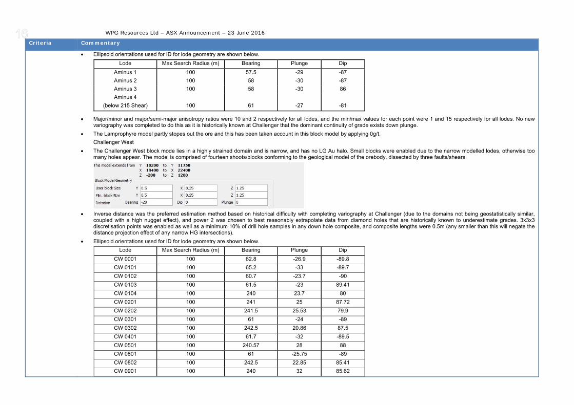
• Ellipsoid orientations used for ID for lode geometry are shown below. Lode Max Search Radius (m) Bearing Plunge Dip
Aminus 1 100 57.5 -29 -87 Aminus 2 100 58 -30 -87 Aminus 3 100 58 -30 86 Aminus 4
(below 215 Shear) 100 61 -27 -81
• Major/minor and major/semi-major anisotropy ratios were 10 and 2 respectively for all lodes, and the min/max values for each point were 1 and 15 respectively for all lodes. No new variography was completed to do this as it is historically known at Challenger that the dominant continuity of grade exists down plunge.
• The Lamprophyre model partly stopes out the ore and this has been taken account in this block model by applying 0g/t. Challenger West
• The Challenger West block mode lies in a highly strained domain and is narrow, and has no LG Au halo. Small blocks were enabled due to the narrow modelled lodes, otherwise too many holes appear. The model is comprised of fourteen shoots/blocks conforming to the geological model of the orebody, dissected by three faults/shears.
• Inverse distance was the preferred estimation method based on historical difficulty with completing variography at Challenger (due to the domains not being geostatistically similar,
coupled with a high nugget effect), and power 2 was chosen to best reasonably extrapolate data from diamond holes that are historically known to underestimate grades. 3x3x3 discretisation points was enabled as well as a minimum 10% of drill hole samples in any down hole composite, and composite lengths were 0.5m (any smaller than this will negate the distance projection effect of any narrow HG intersections).
• Ellipsoid orientations used for ID for lode geometry are shown below. Lode Max Search Radius (m) Bearing Plunge Dip
CW 0001 100 62.8 -26.9 -89.8 CW 0101 100 65.2 -33 -89.7 CW 0102 100 60.7 -23.7 -90 CW 0103 100 61.5 -23 89.41 CW 0104 100 240 23.7 80 CW 0201 100 241 25 87.72 CW 0202 100 241.5 25.53 79.9 CW 0301 100 61 -24 -89 CW 0302 100 242.5 20.86 87.5 CW 0401 100 61.7 -32 -89.5 CW 0501 100 240.57 28 88 CW 0801 100 61 -25.75 -89 CW 0802 100 242.5 22.85 85.41 CW 0901 100 240 32 85.62

WPG Resources Ltd – ASX Announcement – 23 June 2016
Criteria Commentary
• Major/minor and major/semi-major anisotropy ratios were 10 and 4 respectively for both lodes. No new variography was completed to do this as it is historically known at Challenger that the dominant continuity of grade exists down plunge.
• All Block models are validated visually in section to compare with the drill hole data. The blocks were also checked that they matched the lode geology and that lamprophyres had 0g/t applied to them.
Moisture • Tonnages are estimated on a dry basis.
Cut-off parameters
• The resource grade calculation upper cut-off grades are 180.0g/t for all shoots except Aminus, which has a top cut of 80g/t and Challenger West, which has a top cut of 140g/t. These are tried and tested historical cut offs and all composites for block modelling are reviewed to ensure the 97.5th percentile assay is above the relevant cut off to avoid over estimating grade.
• The resource estimate figures have a 5.0g/t lower cut-off for overall grade applied as a lower economic cut-off for underground workings and a 1.5g/t lower cut-off for overall grade applied as a lower economic cut-off for open pits.
Mining factors or assumptions
• Mining factors taken into consideration for the resource estimate are that the resource will be mined using a combination of up-hole retreat stoping (mechanical) and air-leg stoping (for narrow, high grade areas and remnants). The minimum drive dimensions will be 5.0m high by 4.0m wide and the minimum stoping width will be 1.5m. Internal and external dilution has been included in the resource shapes to take in complex structural areas such as thickening of a stope shape due to parasitic folding of the shoot.
Metallurgical factors or assumptions
• Metallurgical factors taken into consideration for the resource estimate are that the ore will continue to be processed at the site CIP plant.
Environmental factors or assumptions
• Environmental impact factors used in the resource estimate are that the waste (which is not acid generating) will continue to be stockpiled on site in designated waste dumps. Process residue will continue to be disposed of in the licensed Tails Storage Facility (TSF2).
Bulk density • Specific gravity (SG) of material at Challenger Gold Mine has been determined in two phases. The initial SG value for the Challenger rock mass was determined during the mine feasibility study, based on core samples from 1,200 to 1,090mRL and was determined to be 2.72 for the Christie Gneiss, which comprises the Challenger deposit. A second pass of SG calculations were conducted in 2012 to determine if the SG had changed with depth. 158 samples were taken from the 320 to 240mRL levels of both Gneiss and intrusive materials. As the host rocks of the Challenger deposit do not have any voids or variation in moisture content, these factors have not been taken into account. It was found that the SGs at the base of the mine comprise:
o Gneiss SG = 2.86 o Lamprophyre SG = 2.92 o Mafic SG = 2.91
• Given that the fully reconciled tonnes for the mine to EOM April 2016 is 99% against the mill, it has been decided to apply the original 2.72 SG to material above the 215 Shear and the new 2.86 SG to material below the 215 Shear.
Classification • The basis for the classification categories for the resource estimate is as follows: Measured o Must be developed/stoped above and below. o Must have sufficient data density to show continuity/structural complexity. o Has geological mapping/face photos to guide modelling. o Must have sufficient information to create a tonnage/grade estimate for production purposes. Data density is used to upgrade an Indicated Resource to Measured, if
there is no adjacent level. o Drillhole spacing typically 20 x 20m diamond drilling in conjunction with extensive 5 to 10m ring spaced sludge drilling and face samples 3 to 4m apart. Indicated o May be developed/stoped on one level only. o Does not have sufficient information to fully inform structural complexity, but shows lode presence (i.e. 25m spaced diamond drilling that cannot provide sufficient
resolution to show up metre-scale parasitic folding). o Does not have sufficient information to fully inform lode continuity (i.e. spacing of drilling such that it is difficult to determine which intercepts are which part of the
system) , but shows lode presence. o Drillhole spacing typically 20 x 20m diamond drilling in conjunction with occasional 5 to 10m ring spaced sludge drilling and face samples 3 to 4m apart.

WPG Resources Ltd – ASX Announcement – 23 June 2016
Criteria Commentary
Inferred o No development had been undertaken adjacent to the resource. o Sufficient information to determine the presence of a lode structure but not enough to determine continuity. o Drillhole spacing not relevant as a single intercept, if identifiable as part of the shoot is used for definition of the inferred resource.
• These classifications have been used by the competent person to classify the Challenger resource estimate and reflect their view of the deposit based on eleven years of experience with the deposit.
Audits or reviews
• The 2016 Challenger mineral resource estimates have been internally reviewed by Gary Jones (WPG Resources Ltd). No changes have been required
Discussion of relative accuracy/ confidence
• The mineral resource estimate has been calculated to the satisfaction of the competent person as being representative of the Challenger deposit, based on available data. The resource estimate has been determined in accordance with techniques used in previous reporting periods.
• The grade calculation techniques used to determine the remnant and generic grades are also used in stope design, these have reconciled as slightly conservative against mill production (Table 2). As a result the confidence in this technique for resource estimation is high.
Table 2 – Reconciliation of Stoping estimates to production, Challenger Gold Mine (fully reconciled levels only), to EOM April 2016. DESIGN RECONCILED MILL FEED RecMillFeed/Design
SHOOT Tonnes (t) Grade (g/t Au) Gold (Oz) Tonnes (t) Grade (g/t Au) Gold (Oz) % t % g/t % Oz M1 1,593,253 8.69 445,174 1,748,784 8.30 466,492 110% 95% 105% M2 1,438,536 5.18 239,797 1,468,532 4.85 227,642 102% 93% 95% M3 220,511 4.43 31,378 263,092 3.67 31,024 119% 83% 99%
SEZ 9,074 3.14 915 9,613 2.87 886 106% 91% 97% M1 SZ 17,354 7.17 4,001 18,496 6.67 3,964 107% 93% 99%
AMINUS 62,149 3.87 7,725 73,822 3.26 7,741 119% 84% 100% CW 478,193 6.53 100,363 627,563 5.88 118,649 131% 90% 118%
TOTAL 3,819,070 6.75 829,353 4,209,902 6.33 856,398 110% 94% 103%
• Aminus and Challenger West have been block modelled for a number of reasons: o These are all high strain lodes, i.e. long and narrow with distinct boudinaged structures. o The lodes can be well domained in areas of high data density, but these zones are separated by areas of little or no data, preventing a generic approach. o These lodes display distinct shoots that conform to the plunge of the ore body o The strong down plunge grade continuity allows their geometry to be used in place of traditional variography parameters. This results in a usable variography which are difficult to
achieve due to the boudinaged nature of the lodes and the high nugget effect. • This block modelling becomes more reliable as additional data is added. The Aminus block model is new and comprises considerable data due to recent development in the
lower portion of the mine. The M3 and SEZ block models are new as a part of feasibility work for the M3/SEZ open pit. The block model of Challenger West is new and comprises CW OD2 and 3 below 510 Level. This area has had additional drilling done in the past financial year and has been remodelled using Leapfrog Geo.
• Due to the high nugget effect experienced at Challenger, the more data a volume of rock has, the better the tonnes and grade estimate, this is reflected in the classification of the resource estimate (see above).

WPG Resources Ltd – ASX Announcement – 23 June 2016
Section 4 - Estimation and Reporting of Ore Reserves
Criteria Commentary
Mineral Resource estimate for conversion to Ore Reserves
• The Challenger mineral resource estimate used as a basis for the conversion to ore reserve estimate was analysed by Luke Phelps, the Senior Mining Engineer at Challenger, who has been a member of the AusIMM for over 18 years. The resource data included diamond drill and sludge assay data, reconciled ore drive and stope data, stope reports for past, present and future stoping areas, stope void DTMs and historical dilution and metallurgical recovery data. This data was compared to the grade control estimates of the April 2016 mineral resource to determine the validity of the resource for conversion to reserve.
• The April 2016 Challenger Mineral Resource is inclusive of the Ore Reserves.
Site visits • Luke Phelps who is employed by WPG Resources, Challenger Gold Operations Pty Ltd, was previously employed by Kingsgate Consolidated Limited, Challenger Gold Operations Pty Ltd at the Challenger Mine Site for over 6 years and has a thorough knowledge of the Challenger ore bodies and the methods of data collection used, as well as the geotechnical and operational extraction considerations associated with the mining methods applicable to the sequence of extraction.
Study status • The Challenger Gold Mine was a fully operational underground mining operation until underground operations were suspended by Kingsgate Consolidated Limited, Challenger Gold Operations Pty Ltd in December 2015. The Challenger Mine Site comprises a CIP and gravity processing plant that was operated by Kingsgate Consolidated Limited, Challenger Gold Operations Pty Ltd until processing was temporarily suspended in March 2016, when WPG Resources acquired the Challenger Gold Operations Pty Ltd with the intent to return the Challenger Gold Mine and the associated gold processing plant to a fully operational status as soon as possible. A full feasibility of each separate lode within the Challenger mineral resource was conducted. Each lode was assessed individually against the required production parameters, the historical and current site operation costs along with the applied modifying factors to determine the economic viability and justification for conversion to reserve.
Cut-off parameters
• The resource tonnes and grade of each level has been analysed individually using site and contractor fixed costs, the contracted schedule of rates against the level physicals, forecast metallurgical recovery based on historical processing plant performance and a set gold price based on corporate guidance. The use of a generic geological resource model for CW and the partial completion of the M2 remnant stopes have required each level to be evaluated individually. The resource used for the reserve estimation has a 5.0g/t lower cut-off applied for underground workings.
Mining factors or assumptions
• The Challenger geological resource models were used to create detailed life of mine (LOM) designs for the extraction of each resource lode. The design was based around an uphole retreat, top down stoping sequence as previously used at Challenger Gold mine and which is planned for future extraction.
• A minimum mining width of 1.5m has been used in the stope design to accommodate the narrow vein Challenger lodes. Based on historical mining at Challenger an external dilution of 40% has been applied in the calculation of all reserves, unless the development has been completed and a full stope analysis has been produced with any variations to this, that have been determined through increased geotechnical input. A specific stope extraction factor has also been applied to each individual level for the reserves estimation. The extraction factor takes into account the material left behind due to the plunge of the orebody and geotechnical stability requirements and does not exceed 90%, unless it is a remnant stope that has already been designed for extraction.
• No Inferred mineral resources have been included in the Ore Reserve estimation.
Metallurgical factors or assumptions
• The existing Challenger CIP and gravity processing facility will be utilised to extract the gold from the April 2016 Ore Reserve ore. A 95% recovery has been applied to the ore reserve estimation based on the historical data of the processing plant.
Environmental • In accordance with the requirements of the PEPR flora and fauna surveys are conducted regularly. • Aboriginal heritage sites have been identified but do not impact on the planned operations. • The water requirements of the operation are being met by the existing borefields.
• Waste rock is Non Acid Forming
• Existing integrated waste landform (IWL) is permitted and has sufficient capacity to store the planned waste generated by the mine plan.
• TSF 2 has sufficient design capacity for the mine plan and all required approvals are in place.
• Site rehabilitation in accordance with the project’s Program for Environmental Protection and Rehabilitation.
Infrastructure • All infrastructure is in the immediate vicinity of the mine site, and includes the open pits and underground mines, mill, waste rock dumps, tailings storage facilities, airstrip and accommodation village.
• Power generation, water, explosives and fuel storage facilities are in the immediate vicinity of the mine and are all located on granted tenements and fully permitted.

WPG Resources Ltd – ASX Announcement – 23 June 2016
Criteria Commentary
• Communications infrastructure is used to provide internet and telephone services to site. • Based on the current production schedule, selected mining methods and transportation requirements for the Challenger operations, no further changes are required to site
infrastructure.
Costs • Projected capital costs are based on historical actuals and assessment of the required activities to support the new mine plan by on site management.
• Operating costs were based on budgeted fixed costs and variable costs based on the new mining contractor rates and LOM Physicals.
• A$3.00/oz transport, treatment and refining costs were based on historical actuals and new site contracts.
• Royalties of A$54.00/oz of gold produced were used in the reserve calculation.
Revenue factors
• The gold price for the ore reserve estimation of A$1,550/oz was been based on Corporate guidance from review of the gold market trend.
• A silver credit of A$2.10/oz of gold produced was based on historical production.
Market assessment
• The assumed gold price of A$1,550/oz for the Ore Reserve estimation has been based on Corporate gold price predictions and is considered conservative in the current gold market.
• The gold market and the available hedge price verses spot price will be continually reviewed under Corporate strategies to continually achieve the most economical outcome for Challenger Gold Mine.
Economic • The preliminary analysis of the reserves was based on cash flow generated by a variety of possible gold prices. The use of the A$1,550/oz was determined by Corporate assumptions derived from past and current gold price conditions and future market predictions that maintain the economic viability of Challenger Gold Mine.
• To demonstrate the ore reserve as economic it has been evaluated through a financial model which has demonstrated that the ore reserve has a positive cash flow.
Social • The Challenger gold mine is being operated under the Challenger Joint Venture, a 50/50 joint venture between WPG and Diversified Minerals Pty Ltd.
• A Native Title Mining Agreement is in place with the Antakirinja Matu-Yankunytjatjara Aboriginal Corporation since 2002. WPG express a policy of indigenous employment wherever possible.
• A Pastoral agreement which covers road access is in place with Jumbuck Pastoral.
• A deed of access for the operation within the WPA is in place with the Department of Defence. The Company works closely with Defence to ensure smooth operations for both the Challenger mine and Defence’s requirements within the Woomera Prohibited Area (WPA).
Other • There are no identified naturally occurring risks that are likely to impact on the Challenger Operation.
• Mineral leases for the Challenger Operation are approved by the State Government of South Australia. There are 2 granted Mineral Leases, ML 6103, on which the mine, and all associated infrastructure lies; and newly granted ML 4657. None of the ore reserves are located on ML 4657.
• The most significant risks for the operation are: • Fall in gold price • Rise in Australian dollar value against US dollar • Capital cost over-run • Operating cost over-run Management systems are in place to mitigate risk on operational risks.
• The Company is assessing the processing of ore at Challenger from its Tarcoola gold project.
Classification • The classification of the ore reserve has been carried out in accordance with the recommendations of the JORC code 2012.
• The reserve results reflect the Competent Person’s view of the deposit. In the opinion of the Competent Person, the gold price for the ore reserve estimation of A$1,550/oz is considered conservative given the current market performance, providing confidence in the economical evaluation used to generate the reserve estimate.
Audits or reviews
• The reserve estimate has been reviewed internally by Marcus Doyle (General Manager) and Jon Holden (Mining Manager) of Challenger Gold Operation Pty Ltd, Challenger Gold Mine.
Discussion of relative
• The April 2016 ore resource was analysed on a level by level basis to derive the ore reserve estimates. The historical and budgeted site fixed costs and operational contractor rates

WPG Resources Ltd – ASX Announcement – 23 June 2016
Criteria Commentary
accuracy/ confidence
generate a high level of confidence in the costs applied to the estimated reserve.
• The gold price for the ore reserve estimation of A$1,550/oz is considered conservative given the current market performance, providing confidence in the economical evaluation used to generate the reserve estimate.
• The key modifying factors of 40% dilution, specific level extraction factor not greater than 90% for anything other than designed remnant material and 95% milling recovery are consistent with historical performance of the areas and lodes contained in the reserve.
• It is expected there will be a good reconciliation on tonnes and gold grade mined between Ore Reserve estimates and mining operations.