Embed Size (px)
Citation preview

Formula Hybrid ESF -- Part 1
INTRODUCTION
Part 1 of the Formula Hybrid ESF is intended to help teams solidify those design decisions that need to be made early in the program. This will also help the technical reviewers identify possible areas of concern early.
Many of the fields in this form will also be found in the ESF Part 2 and the information in those fields will need to be reentered when the ESF Part 2 is submitted.
It is expected that some of the information will change during the development of the vehicle. Teams should not feel “locked in” by the data provided here, however data entered in the ESF Part 2 will be considered final.
The information in this form will also be provided to the design judges, so teams may expect questions during the design event relating to why a particular aspect of the vehicle was changed during development.
INSTRUCTIONS AND REQUIREMENTS
.1. Enter the information requested as accurately as possible. If a particular portion of the design
has not been finalized, give a short description of the options being considered.
2. Please submit any questions, corrections and suggestions for improvement to:
http://www.formula-hybrid.org/level2/support/index.php
3. When completed, this document must be converted to a pdf and submitted to:
http://formula-hybrid.com/uploads/
2017 Formula Hybrid ESF Part 1 1 Rev 0 – May 9, 2023
Table of Contents
Section 1 Vehicle Overview............................................................................................2
Section 2 Frame and Body..............................................................................................3
Section 3 Engine..............................................................................................................43.1 Engine Data.........................................................................................................................43.2 Architecture..........................................................................................................................4
Section 4 Electrical System Overview...........................................................................54.1 Block Diagram......................................................................................................................54.2 Vehicle Layout.....................................................................................................................54.3 Electrical System Parameters..............................................................................................64.4 Firewall(s)............................................................................................................................6
Section 5 Tractive System..............................................................................................75.1 Motor(s)................................................................................................................................75.2 Motor Controller...................................................................................................................7
Section 6 Accumulator System......................................................................................86.1 Accumulator Pack................................................................................................................86.2 Cell Description - Batteries..................................................................................................86.3 Cell Description - Capacitors...............................................................................................96.4 Cell Configuration................................................................................................................96.5 Lithium-Ion Pouch Cells.......................................................................................................96.6 Accumulator Management System (AMS).........................................................................106.7 Charging............................................................................................................................106.8 Accumulator Container/Housing........................................................................................116.9 Shutdown Circuit................................................................................................................116.10 IMD....................................................................................................................................11
Section 7 GLV System...................................................................................................137.1 GLV System Data..............................................................................................................13
2017 Formula Hybrid ESF Part 1 2 Rev 0 – May 9, 2023

List of FiguresFigure 1- Electrical System Block Diagram........................................................................................5Figure 2 - Locations of major TS components...................................................................................5Figure 3 – Safety Shutdown Circuit Schematic................................................................................11
Must be hyperlinked!
List of TablesTable 1 - Engine Data........................................................................................................................4Table 2 - General Electrical System Parameters...............................................................................6Table 3 - Motor Specifications............................................................................................................7Table 4 - Motor Controller Specifications...........................................................................................7Table 5 - Main Accumulator Parameters............................................................................................8Table 6 - Main Cell Specification........................................................................................................9Table 7 - Capacitor Specifications......................................................................................................9Table 8 - AMS Data..........................................................................................................................10Table 9 - Accumulator Charging Data..............................................................................................10Table 10 - IMD parameters..............................................................................................................12Table 11 - GLV Data........................................................................................................................13
Must be hyperlinked!
2017 Formula Hybrid ESF Part 1 3 Rev 0 – May 9, 2023

TITLE PAGE
Please include team logo, car picture, team picture, etc..
University Name: Lafayette College
Team Name: Lafayette Motor Sports
Car Number: 217
Main Team Contact for ESF related questions:
Name: Graham Thomas
e-mail: [email protected]
2017 Formula Hybrid ESF Part 1 1 Rev 0 – May 9, 2023
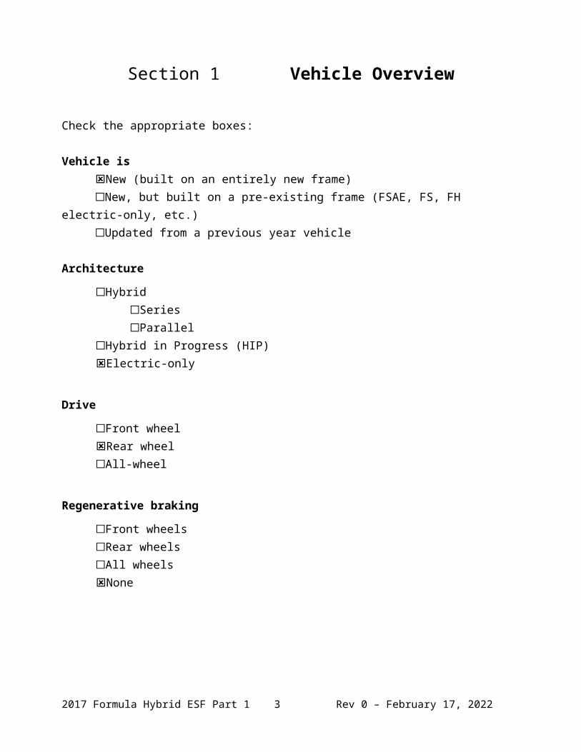
Section 1 Vehicle Overview
Check the appropriate boxes:
Vehicle isNew (built on an entirely new frame)New, but built on a pre-existing frame (FSAE, FS, FH electric-only, etc.)Updated from a previous year vehicle
Architecture
HybridSeriesParallel
Hybrid in Progress (HIP)Electric-only
Drive
Front wheelRear wheelAll-wheel
Regenerative braking
Front wheelsRear wheelsAll wheelsNone
2017 Formula Hybrid ESF Part 1 2 Rev 0 – May 9, 2023
Section 2 Frame and Body
List the materials used and the construction methodology for the frame and body. Include CAD drawings, photos or sketches as appropriate.
Frame
Materials
Minimum FSAE required Steel Bending & Buckling strength calculations
o Youngs Modulus = 200 GPao Yield Strength = 305 MPao Ultimate Strength = 365 MPa
Joining Methods and Construction
Welds We are outsourcing manufacturing of our frame to VR3
Body
Materials
Fiberglass
Construction
Student fabricated in-house No CAD drawings for body yet
2017 Formula Hybrid ESF Part 1 3 Rev 0 – May 9, 2023
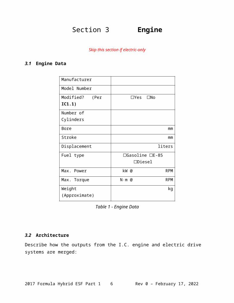
Section 3 Engine
Skip this section if electric-only
3.1 Engine Data
Manufacturer
Model Number
Modified? (Per IC1.1) Yes No
Number of Cylinders
Bore mm
Stroke mm
Displacement liters
Fuel type Gasoline E-85 Diesel
Max. Power kW @ RPM
Max. Torque N⋅m @ RPM
Weight (Approximate) kg
Table 1 - Engine Data
3.2 Architecture
Describe how the outputs from the I.C. engine and electric drive systems are merged:
2017 Formula Hybrid ESF Part 1 4 Rev 0 – May 9, 2023

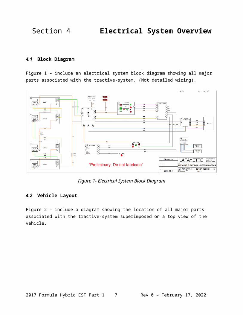
Section 4 Electrical System Overview
4.1 Block Diagram
Figure 1 – include an electrical system block diagram showing all major parts associated with the tractive-system. (Not detailed wiring).
Figure 1- Electrical System Block Diagram
4.2 Vehicle Layout
Figure 2 – include a diagram showing the location of all major parts associated with the tractive-system superimposed on a top view of the vehicle.
Figure 2 - Locations of major TS components
2017 Formula Hybrid ESF Part 1 5 Rev 0 – May 9, 2023
4.3 Electrical System Parameters
Fill out the following table:
Nominal Tractive System Voltage (TSV) 96 VDC
Max. TSV (typically this is during charging) 120 VDC
Control System voltage (GLV) 24 VDC
Total Accumulator capacity 16 Wh
Accumulator type (Lead-acid, Li-Ion, NiMH, Ultracap…) Li-Ion Polymer
Number of electric motors. (Total) 1
Are wheel motors used? Yes No
Table 2 - General Electrical System Parameters
4.4 Firewall(s)
Description/materials
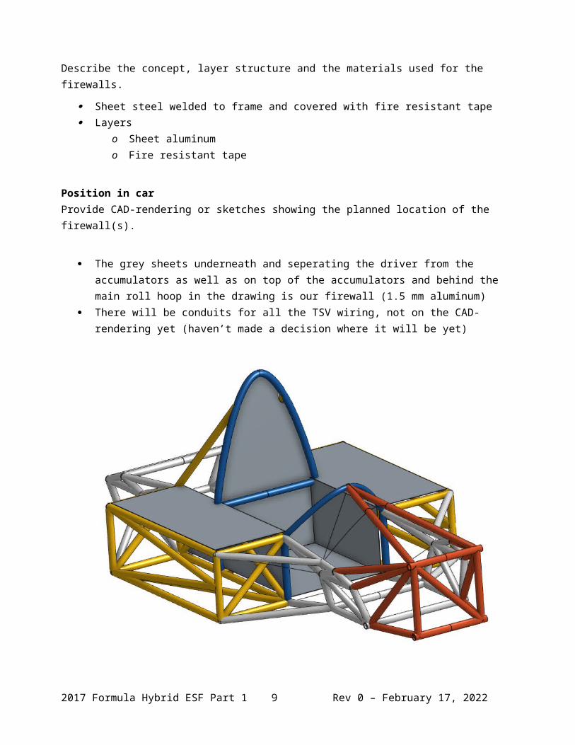
Describe the concept, layer structure and the materials used for the firewalls.
Sheet steel welded to frame and covered with fire resistant tape Layers
o Sheet aluminumo Fire resistant tape
Position in carProvide CAD-rendering or sketches showing the planned location of the firewall(s).
The grey sheets underneath and seperating the driver from the accumulators as well as on top of the accumulators and behind the main roll hoop in the drawing is our firewall (1.5 mm aluminum)
There will be conduits for all the TSV wiring, not on the CAD-rendering yet (haven’t made a decision where it will be yet)
2017 Formula Hybrid ESF Part 1 6 Rev 0 – May 9, 2023
2017 Formula Hybrid ESF Part 1 7 Rev 0 – May 9, 2023
Section 5 Tractive System
5.1 Motor(s)
Add additional tables if multiple motor types are used
Manufacturer HPEVS, Inc
Model Number AC50-27.28.11
Motor Type (PM, Induction, DC Brush…) AC-50 Induction Motor Brushless
Number of motors of this type used 1
Nominal motor voltage (Vrms l-l or Vdc) 96
Nominal / Peak motor current (A or A/phase) Nom: 200 Peak: 600
Nominal / Peak motor power Nom: 52 HP Peak: 100 HP
Table 3 - Motor Specifications
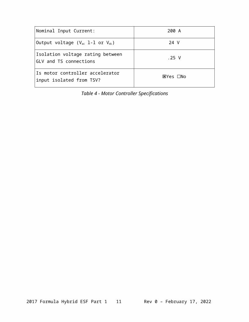
5.2 Motor Controller
Manufacturer Curtis
Model Number 1238R
Number of controllers of this type used: 1
Maximum Input voltage: 96 V
Nominal Input Current: 200 A
Output voltage (Vac l-l or Vdc) 24 V
Isolation voltage rating between GLV and TS connections
.25 V
Is motor controller accelerator input isolated from TSV?
Yes No
Table 4 - Motor Controller Specifications
2017 Formula Hybrid ESF Part 1 8 Rev 0 – May 9, 2023

Section 6 Accumulator System
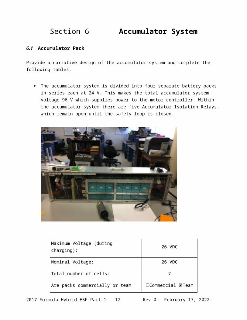
6.1 Accumulator Pack
Provide a narrative design of the accumulator system and complete the following tables.
The accumulator system is divided into four separate battery packs in series each at 24 V. This makes the total accumulator system voltage 96 V which supplies power to the motor controller. Within the accumulator system there are five Accumulator Isolation Relays, which remain open until the safety loop is closed.
Maximum Voltage (during charging): 26 VDC
Nominal Voltage: 26 VDC
Total number of cells: 7
Are packs commercially or team constructed?
Commercial Team
Total Capacity: 4 Wh
Maximum Segment Capacity: 4.8384 MJ
Table 5 - Main Accumulator Parameters
2017 Formula Hybrid ESF Part 1 9 Rev 0 – May 9, 2023
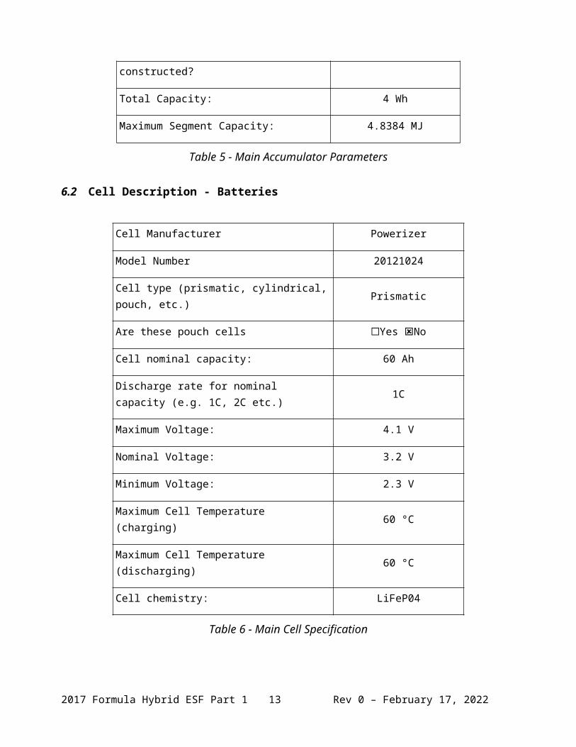
6.2 Cell Description - Batteries
Cell Manufacturer Powerizer
Model Number 20121024
Cell type (prismatic, cylindrical, pouch, etc.) Prismatic
Are these pouch cells Yes No
Cell nominal capacity: 60 Ah
Discharge rate for nominal capacity (e.g. 1C, 2C etc.)
1C
Maximum Voltage: 4.1 V
Nominal Voltage: 3.2 V
Minimum Voltage: 2.3 V
Maximum Cell Temperature (charging) 60 °C
Maximum Cell Temperature (discharging) 60 °C
Cell chemistry: LiFeP04
Table 6 - Main Cell Specification
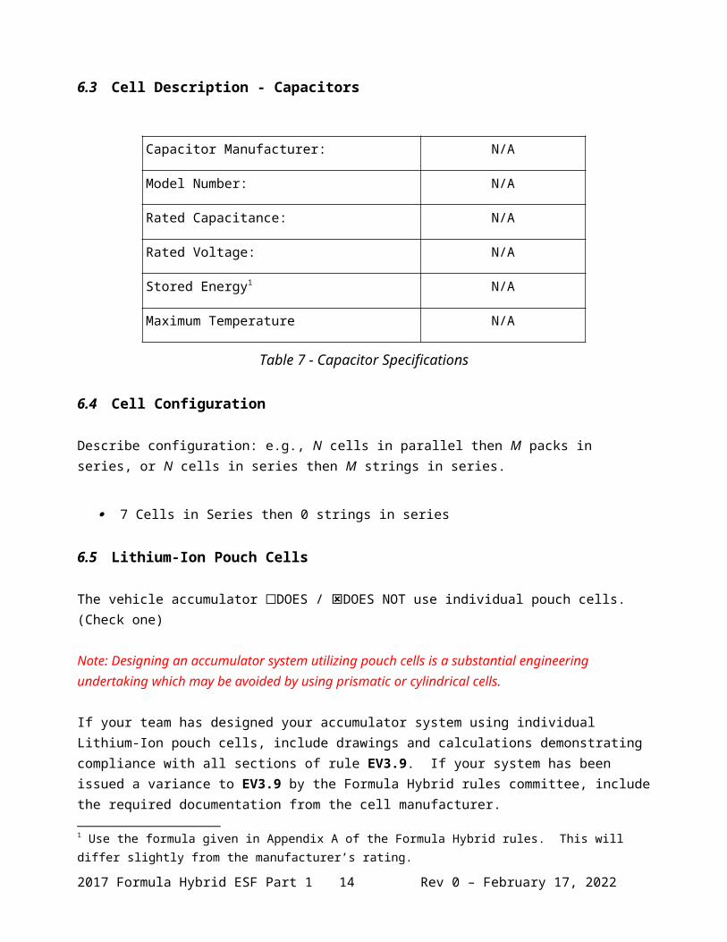
6.3 Cell Description - Capacitors
Capacitor Manufacturer: N/A
Model Number: N/A
Rated Capacitance: N/A
Rated Voltage: N/A
Stored Energy1 N/A
Maximum Temperature N/A
1 Use the formula given in Appendix A of the Formula Hybrid rules. This will differ slightly from the manufacturer’s rating.
2017 Formula Hybrid ESF Part 1 10 Rev 0 – May 9, 2023

Table 7 - Capacitor Specifications
6.4 Cell Configuration
Describe configuration: e.g., N cells in parallel then M packs in series, or N cells in series then M strings in series.
7 Cells in Series then 0 strings in series
6.5 Lithium-Ion Pouch Cells
The vehicle accumulator DOES / DOES NOT use individual pouch cells. (Check one)
Note: Designing an accumulator system utilizing pouch cells is a substantial engineering undertaking which may be avoided by using prismatic or cylindrical cells.
If your team has designed your accumulator system using individual Lithium-Ion pouch cells, include drawings and calculations demonstrating compliance with all sections of rule EV3.9. If your system has been issued a variance to EV3.9 by the Formula Hybrid rules committee, include the required documentation from the cell manufacturer.
6.6 Accumulator Management System (AMS)
AMS Manufacturer Lafayette College
Model Number N/A
Number of AMSs 1 per cell
Upper Cell Voltage Trip 4.05 V
Lower Cell Voltage Trip 2.35 V
Temperature Trip 50 °C
Table 8 - AMS Data
6.7 Charging
Charger Manufacturer TDK-Lambda
Model Number GENH30-25-U
2017 Formula Hybrid ESF Part 1 11 Rev 0 – May 9, 2023
Maximum Charging Power: .48 kW
GLV/TS isolation location:(i.e. cell boards, main unit, etc.)
Main unit
UL Certification? Yes No
Maximum Charging Voltage: 29 V
Maximum Charging Current: 20 A
Input Voltage: 120 VAC single phase
Input Current: 9.5 A
Table 9 - Accumulator Charging Data
6.8 Accumulator Container/Housing
Describe the design of the accumulator container. Include the housing material specifications and construction methods.
The accumulator container is designed with 8020 aluminum. All of the walls and barriers were designed to the rulebook set by FSAE electric to ensure that we it will pass tech. but more importantly be safe to use. There are small air intakes and fans to ensure that the packs do not overheat during charging or usage. We also took the time to make sure that every structural component is well within our factor of safety.
Where will the accumulators be located?
2 accumulator packs on each side of the driver
Will you be taking advantage of the virtual accumulator housing rule? (EV3.3)
No
6.9 Shutdown Circuit
Include a schematic of the shutdown circuit for your vehicle including all major components in the loop. Note: The design of the shutdown circuit and team members understanding of how it works is extremely important. Take the time to be sure it is right.
The Red Circles on the Diagram are our emergency stops. There is an emergency stop in the cockpit for the driver and one on each side of the car around the roll hoop (left and
2017 Formula Hybrid ESF Part 1 12 Rev 0 – May 9, 2023
right). There is also an emergency stop on the brake pedal over travel switch, which is in the foot pedals box. The emergency shut off switches are either a push button that must stay pulled to keep the car running or turn on. There are also key switches that will be on the roll hoop.
Figure 3 – Safety Shutdown Circuit Schematic
6.10 IMD
Describe the IMD used and complete the following table:
Standard Bender board that will be wired correctly
Manufacturer Bender
2017 Formula Hybrid ESF Part 1 13 Rev 0 – May 9, 2023
Model Number IR155-3204
Set response value: _100__ kΩ ( __1042_ Ω/Volt)
Table 10 - IMD parameters
2017 Formula Hybrid ESF Part 1 14 Rev 0 – May 9, 2023
Section 7 GLV System
7.1 GLV System Data
Provide a brief description of the GLV system and complete the following table.
We are using two 24V batteries to power the following components: VSCADA, cockpit controls/display, brake press/over-travel switch, accelerator pedal potentiometers, and tentative cooling controller
GLV System Voltage 24 V
GLV Main Fuse Rating 20 A
GLV Accumulator type IMH
How is the GLV storage recharged? Commercial charger
Table 11 - GLV Data
2017 Formula Hybrid ESF Part 1 15 Rev 0 – May 9, 2023