Embed Size (px)
Citation preview
2016 NYCECC TABULAR ANALYSISResidential
NYCECC Citation Provision Item Description Proposed Design Value Code Prescriptive Value (ECC) Supporting Documentation Additional Notes
R401.3 Certificate (Mandatory) Permanent certificate posted on the
electrical distribution panel.
Sample Text: Certificate provided as per code
requirements.
A permanent certificate shall be completed by the
builder or registered design professional and posted
on the wall in the space where the furnace is located,
a utility room or an approved location inside the
building. The certificate shall stateinsulation R-values,
U-factors and the solar heat gain coefficient (SHGC)
of fenestration, results from any required duct system
and building envelope air leakage testing done on the
building, and equipment efficiencies. When located on
anelectrical panel the certificate shall not cover or
obstruct the visibility of any required labels.
Sample Text: See architectural plans, A-XXX, A-XXX
and specifications drawing A-XXX
R401.4, Appendix RB Solar-ready requirements
(Mandatory)
Solar-ready requirements Sample Text: Solar-ready requirements comply
with R401.4.
Detached one- and two-family dwelling and multiple
single-familydwellings (townhouses) shall meet the
requirements of Appendix RB of this code.
Sample Text: See architectural plans, A-XXX, A-XXX
and specifications drawing A-XXX
R402.1.2, Table
R402.1.2
Insulation and fenestration
criteria
Sample Text:
Above-grade wood-framed wall 2x4
framing, 16" o.c.
Mass basement wall with wood furring
Sample Text:
Fenestration U-factor = 0.32
Skylight U-Factor= N/A
Glazed fenestration SHGC= 0.40
Ceiling R-value= 49
Wood Frame Wall R-value= 13+10
Mass wall value= N/A
Floor R-value= 30
Basement wall R-value= R-19 in wood-frame
Slab R-value & depth= R-10, 4 ft.
Crawl space wall R-value= N/A
Sample Text:
Fenestration U-factor = 0.32
Skylight U-factor= 0.55
Glazed fenestration SHGC= 0.40
Ceiling R-value= 49
Wood Frame Wall R-value= 13+10
Mass wall value= 15/20
Floor R-value= 30
Basement wall R-value= 15/19
Slab R-value & depth= R-10, 4 ft.
Crawl space wall R-value= 15/19
Sample Text: Vertical fenestration:
A-XX1-XX2 (Building Elevations)
A-XY1 (Schedules)
R402.1.3, Table
R402.1.2
R-value computation Sample Text:
Exterior wood-framed wall 2x4 framing,
16" o.c.
Sample Text:
R-13 batt cavity insulation and R-10 rigid
insulation (R-5/inch).
Sample Text: R-13 + R-10ci Sample Text: Exterior Wall Type 1:
A-XX0 (1st Floor Plan)
2/A-XXX (Wall Details)
Where there is more than one layer of
insulation, the R-values are summed.
Although other products and features,
such as finish materials, air films and
airspaces, may contribute to overall
energy efficiency, when determining the
R-value in the code, these additional
items are not considered and do not
contribute to the nominal R-value.
R402.1.4, Table
R402.1.2, Table
R402.1.4
U-factor alternative Sample Text: Exterior 8" block wall with R-
10ci and R-13 batt in metal furring
Sample Text:
U-factor calculated using ASHRAE 90.1-2013
Appendix A
Ru - 2.07 (Table A3.1-3, 8" block, 115#)
R - 10.5 (Table A3.1-4, 10ci)
R - 4.7 (Table A3.1-4, R-13 in 3.5 metal stud)
U = 1/(2.07 + 10.5 + 4.7) = 0.058
Sample Text:
Mass wall
U = 0.060
Sample Text: Exterior Wall Type 1:
A-XX0 (1st Floor Plan)
2/A-XXX (Wall Details)
R402.2.1, R402.1.2,
R402.1.4, R402.1.5
Ceilings with attic spaces Insulation in ceiling with attic space Sample Text: Insulation extends over wall top
plate at eaves, so R-38 has been used.
R-38 installed over 100 percent of the ceiling area; the
full height of uncompressed R-38 insulation extends
over the wall top plate at the eaves.
Sample Text: A-XXX (Roof Plan) A-XXX (Wall
Section) A-XXX (Wall Details)
R402.2.3 Eave baffle Sample Text: Eave baffles Sample Text: Baffle is greater than the size of the
vent it is installed adjacent to and extends over
the top of the attic insulation.
For air-permeable insulations in vented attics, a baffle
shall be installed adjacent to soffit and eave vents.
Baffles shall maintain an opening equal or greater
than the size of the vent, extend over the top of the
attic insulation, and may be any solid material.
Sample Text: A-XXX (Roof Plan) A-XXX (Wall
Section) A-XXX (Wall Details)
Page 1 of 6 3/14/2018
2016 NYCECC TABULAR ANALYSISResidential
NYCECC Citation Provision Item Description Proposed Design Value Code Prescriptive Value (ECC) Supporting Documentation Additional Notes
R402.2.4 Access hatches and doors Attic access hatch Sample Text: Access door to uninsulated attic is
weather-stripped and insulated to R-49
Access doors from conditioned spaces to
unconditioned spaces (e.g., attics and crawl spaces)
shall be weatherstripped and insulated to a level
equivalent to the insulation on the surrounding
surfaces. Access shall be provided to all equipment
which prevents damaging or compressing the
insulation. A wood framed or equivalent baffle or
retainer is required to be provided when loose fill
insulation is installed, the purpose of which is to
prevent the loose fill insulation from spilling into the
living space when the attic access is opened, and to
provide a permanent means of maintaining the
installed R-value of the loose fill insulation.
Sample Text: A-XXX (Roof Plan) A-XXX (Building
Section)
R402.2.6, Table
R402.2.6, Table
R402.1.4
Steel-frame ceilings, walls
and floors
Steel frame walls Sample Text: Steel frame walls insulated to
R-13 + R-15ci
Sample Text: Code minimum R-13 + R-12.7ci Sample Text: A-XXX (Wall Section) A-XXX (Wall
Details)
R402.2.8 Floors Subfloor insulation installation Sample Text: XPS adhered to underside of
subfloor assembly and fastened to maintain
permanent contact with subfloor decking.
Floor framing-cavity insulation shall be installed to
maintain permanent contact with the underside of the
subfloor decking.
Sample Text: Note provided in general notes as well
as on ground floor or foundation plan.
R402.2.9, Sections
R402.1.2 and
R402.2.8
Basement walls Basement walls Sample Text:
R-19 batt insulation in wood-framing
R-19 batt in wood-framing Sample Text: A-XXX (Wall Section) A-XXX (Wall
Details)
R402.2.10 Slab-on-grade floors Slab on grade floor insulation and location Sample Text: R-10ci, located as per code
requirements.
R-10 minimum installed 4 feet Sample Text: A-XXX (Floor Plan) A-XXX (Wall
Section) A-XXX (Wall Details)
R402.2.11 Crawl space walls Unvented crawl space insulation Sample Text:
R-15ci on the interior walls
Minimum R-15ci on the interior walls. Crawl space wall
insulation shall be permanently fastened to the wall
and extend downward from the floor to the finished
grade level and then vertically and/or horizontally for
at least an additional 24 inches (610 mm).
Sample Text: A-XXX (Floor Plan) A-XXX (Wall
Section) A-XXX (Wall Details)
R402.2.13, R402.3.5
and Table R402.1.2
Sunroom insulation &
fenestration
Sunroom (400 SF) thermally isolated from
home
Sample Text:
Walls: R-13
Ceiling: R-19
Fenestration: U-0.40
Sample Text:
For thermally isolated sunrooms,
Walls: R-13
Ceiling: R-19
Fenestration: U-0.45
Sample Text: A-XXX (Floor Plan) A-XXX (Wall
Section) A-XXX (Wall Details)
R402.3.1 U-Factor Fenestration U-Factor Sample Text: Window A, U = 0.30 Sample Text: Window A, U maximum = U-0.32 Sample Text: Vertical fenestration: A-301-302
(Building Elevations) A-501 (Schedules)
R402.3.2 Glazed fenestration SHGC Fenestration SHGC Sample Text: Window A, SHGC = 0.4 Sample Text: Window A, SHGC maximum = U-0.40
R402.3.3 Glazed fenestration
exemption
Glazing U-factor requirement exemption Sample Text:
Window X, Stained Glass window, U-0.8
(8 ft2exempt from U-factor requirements)
Up to 15 SF (1.4 m²) of glazed fenestration per
dwelling unit shall be permitted to be exempt from U-
factor and SHGC requirements in Section R402.1.2.
Sample Text: Vertical fenestration: A-301-302
(Building Elevations) A-501 (Schedules)
R402.3.4 Opaque door exemption Door U-factor requirement exemption Sample Text:
Door A, U-1.5
(22 ft2door exempt from U-factor requirements)
One side-hinged opaque door assembly up to 24
square feet (2.22 m²) in area is exempted from the U-
factor requirement in Section R402.1.4.
Sample Text: Vertical fenestration: A-XXX-XXY
(Building Elevations) A-XXX (Schedules)
Page 2 of 6 3/14/2018
2016 NYCECC TABULAR ANALYSISResidential
NYCECC Citation Provision Item Description Proposed Design Value Code Prescriptive Value (ECC) Supporting Documentation Additional Notes
R402.4, R402.4.1.2,
R402.4.1.3
Air leakage (Mandatory) Air leakage testing statement Sample Text: Building thermal envelope to be
tested to no more than 3 ACH @ 50 PA and
witnessed by the Progress Inspector as indicated
on TR-8 inspection IA7.
Less than 3 ACH. A written report of the test results
shall be prepared and signed by the party conducting
the test and provided to the code official and
shallinclude the items listed in R402.4.1.2.
Sample Text: EN-XXX notes
R402.4.1, R402.4.1.1,
Table R402.4.1.
Building thermal envelope Air sealing details Sample Text: Building thermal envelope sealed
as per code requirements. See air sealing
details.
The building thermal envelope shall be durably sealed
to limit infiltration. The sealing methods shall be in
accordance with Table R402.4.1.1.
Sample Text: A-XXX (Floor Plan) A-XXX (Wall
Section) A-XXX (Wall Details)
R402.4.2 Fireplaces Fireplaces Sample Text: Tight-fitting doors used on a
masonry fireplace are listed and labeled in
accordance with UL 907.
New wood-burning fireplaces and fireplace units that
are designed to allow an open burn shall have tight-
fitting flue dampers or tight-fitting doors. Tight-fitting
doors used on a factory built fireplace listed and
labeled in accordance with UL 127 or on a factory-
built fireplace unit listed and labeled in accordance
with UL 127 shall be tested and listed. Tight-fitting
doors used on a masonry fireplace shall be listed and
labeled in accordance with UL 907. New wood-
burning fireplaces and fireplace units that are
designed to allow an open burn shall be provided with
a source of outdoor combustion air as required by the
fireplace construction provisions of the NYC Building
Code.
Sample Text: A-XXX (Schedule) A-XXX (Floor Plan)
A-XXX (Specifications)
R402.4.3 Fenestration air leakage Window infiltration rates Sample Text:
All fenestration rated at 0.25 cfm/ft²
All doors rated at 0.4 cfm/ft²
Windows, skylights and sliding glass doors shall have
an air infiltration rate of no more than 0.3 cfm/ft²
swinging doors no more than 0.5 cfm/ft²
Sample Text: Fenestration Schedule: A-XXX-XXY
(Building Elevations) A-XXX (Schedules)
R402.4.4 Rooms containing fuel-
burning appliances
Rooms containing fuel-burning appliances
and their insulation requirements
Sample Text:
Boiler B-1 is direct vent
SWH-1 is direct vent
Sample Text:
Direct vent applicances are exempt from the
requirement.
Sample Text: A-XXX (Floor Plan) A-XXX (Wall
Section) A-XXX (Wall Details)
R402.4.5 Recessed lighting Recessed lighting sealing Sample Text: Sealing at exterior lights provided
as per code requirements.
Recessed luminaires installed in the building thermal
envelope are sealed per requirements.
Sample Text: A-XXX (Floor Plan) A-XXX (Wall
Section) A-XXX (Wall Details)
R402.4.6 Tenant separation walls
(Mandatory)
Tenant separation walls Sample Text: Fire separation between
multifamily units has minimum of R-10.
Fire separations between dewlling units in two-family
dwellings and multiple single-family dwellings
(townhouses) shall be insulated to no less than R-10
and the walls shall be air sealed according to Section
R402.4.
Sample Text: A-XXX (Floor Plan) A-XXX (Wall
Section) A-XXX (Schedules)
R403.1.1 Programmable thermostat Thermostats Sample Text:
(1) programmable thermostat for Mini-split unit
The thermostat controlling the primary heating or
cooling system of the dwelling unit shall be capable of
controlling the heating and cooling system on a daily
schedule to maintain different temperature set points
at different times of the day. Thermostat shall have
ability to setback temperatures down to 55°F (13°C),
or up to 85°F (29°C). Initial set point to be no higher
than 70°F (21°C) in heating and 78°F (26°C) in
cooling.
Sample Text: M-XXX (Details), M-XXX (Schedule)
R403.1.2 Heat pump supplementary
heat (Mandatory)
Sample Text: Split heat pumpsystem, HP-
1
Sample Text: Electric heat shall be enabled only
when the heat pump cannot meet load.
Except during defrost, supplementary electric heat to
be prevented from coming on when heat pump
compressor can meet load.
Sample Text: M-XXX (Details), M-XXX (Schedule)
Page 3 of 6 3/14/2018
2016 NYCECC TABULAR ANALYSISResidential
NYCECC Citation Provision Item Description Proposed Design Value Code Prescriptive Value (ECC) Supporting Documentation Additional Notes
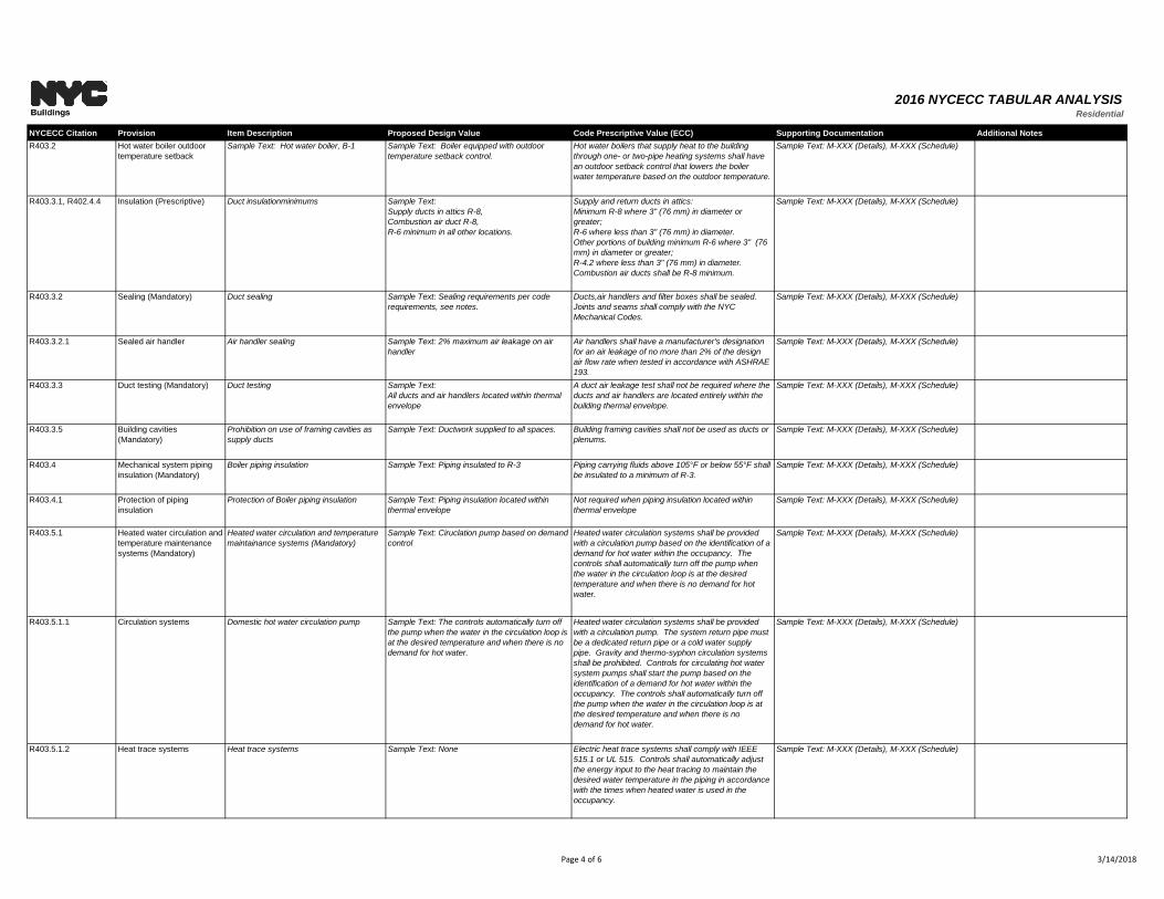
R403.2 Hot water boiler outdoor
temperature setback
Sample Text: Hot water boiler, B-1 Sample Text: Boiler equipped with outdoor
temperature setback control.
Hot water boilers that supply heat to the building
through one- or two-pipe heating systems shall have
an outdoor setback control that lowers the boiler
water temperature based on the outdoor temperature.
Sample Text: M-XXX (Details), M-XXX (Schedule)
R403.3.1, R402.4.4 Insulation (Prescriptive) Duct insulationminimums Sample Text:
Supply ducts in attics R-8,
Combustion air duct R-8,
R-6 minimum in all other locations.
Supply and return ducts in attics:
Minimum R-8 where 3" (76 mm) in diameter or
greater;
R-6 where less than 3" (76 mm) in diameter.
Other portions of building minimum R-6 where 3" (76
mm) in diameter or greater;
R-4.2 where less than 3" (76 mm) in diameter.
Combustion air ducts shall be R-8 minimum.
Sample Text: M-XXX (Details), M-XXX (Schedule)
R403.3.2 Sealing (Mandatory) Duct sealing Sample Text: Sealing requirements per code
requirements, see notes.
Ducts,air handlers and filter boxes shall be sealed.
Joints and seams shall comply with the NYC
Mechanical Codes.
Sample Text: M-XXX (Details), M-XXX (Schedule)
R403.3.2.1 Sealed air handler Air handler sealing Sample Text: 2% maximum air leakage on air
handler
Air handlers shall have a manufacturer's designation
for an air leakage of no more than 2% of the design
air flow rate when tested in accordance with ASHRAE
193.
Sample Text: M-XXX (Details), M-XXX (Schedule)
R403.3.3 Duct testing (Mandatory) Duct testing Sample Text:
All ducts and air handlers located within thermal
envelope
A duct air leakage test shall not be required where the
ducts and air handlers are located entirely within the
building thermal envelope.
Sample Text: M-XXX (Details), M-XXX (Schedule)
R403.3.5 Building cavities
(Mandatory)
Prohibition on use of framing cavities as
supply ducts
Sample Text: Ductwork supplied to all spaces. Building framing cavities shall not be used as ducts or
plenums.
Sample Text: M-XXX (Details), M-XXX (Schedule)
R403.4 Mechanical system piping
insulation (Mandatory)
Boiler piping insulation Sample Text: Piping insulated to R-3 Piping carrying fluids above 105°F or below 55°F shall
be insulated to a minimum of R-3.
Sample Text: M-XXX (Details), M-XXX (Schedule)
R403.4.1 Protection of piping
insulation
Protection of Boiler piping insulation Sample Text: Piping insulation located within
thermal envelope
Not required when piping insulation located within
thermal envelope
Sample Text: M-XXX (Details), M-XXX (Schedule)
R403.5.1 Heated water circulation and
temperature maintenance
systems (Mandatory)
Heated water circulation and temperature
maintainance systems (Mandatory)
Sample Text: Ciruclation pump based on demand
control
Heated water circulation systems shall be provided
with a circulation pump based on the identification of a
demand for hot water within the occupancy. The
controls shall automatically turn off the pump when
the water in the circulation loop is at the desired
temperature and when there is no demand for hot
water.
Sample Text: M-XXX (Details), M-XXX (Schedule)
R403.5.1.1 Circulation systems Domestic hot water circulation pump Sample Text: The controls automatically turn off
the pump when the water in the circulation loop is
at the desired temperature and when there is no
demand for hot water.
Heated water circulation systems shall be provided
with a circulation pump. The system return pipe must
be a dedicated return pipe or a cold water supply
pipe. Gravity and thermo-syphon circulation systems
shall be prohibited. Controls for circulating hot water
system pumps shall start the pump based on the
identification of a demand for hot water within the
occupancy. The controls shall automatically turn off
the pump when the water in the circulation loop is at
the desired temperature and when there is no
demand for hot water.
Sample Text: M-XXX (Details), M-XXX (Schedule)
R403.5.1.2 Heat trace systems Heat trace systems Sample Text: None Electric heat trace systems shall comply with IEEE
515.1 or UL 515. Controls shall automatically adjust
the energy input to the heat tracing to maintain the
desired water temperature in the piping in accordance
with the times when heated water is used in the
occupancy.
Sample Text: M-XXX (Details), M-XXX (Schedule)
Page 4 of 6 3/14/2018
2016 NYCECC TABULAR ANALYSISResidential
NYCECC Citation Provision Item Description Proposed Design Value Code Prescriptive Value (ECC) Supporting Documentation Additional Notes
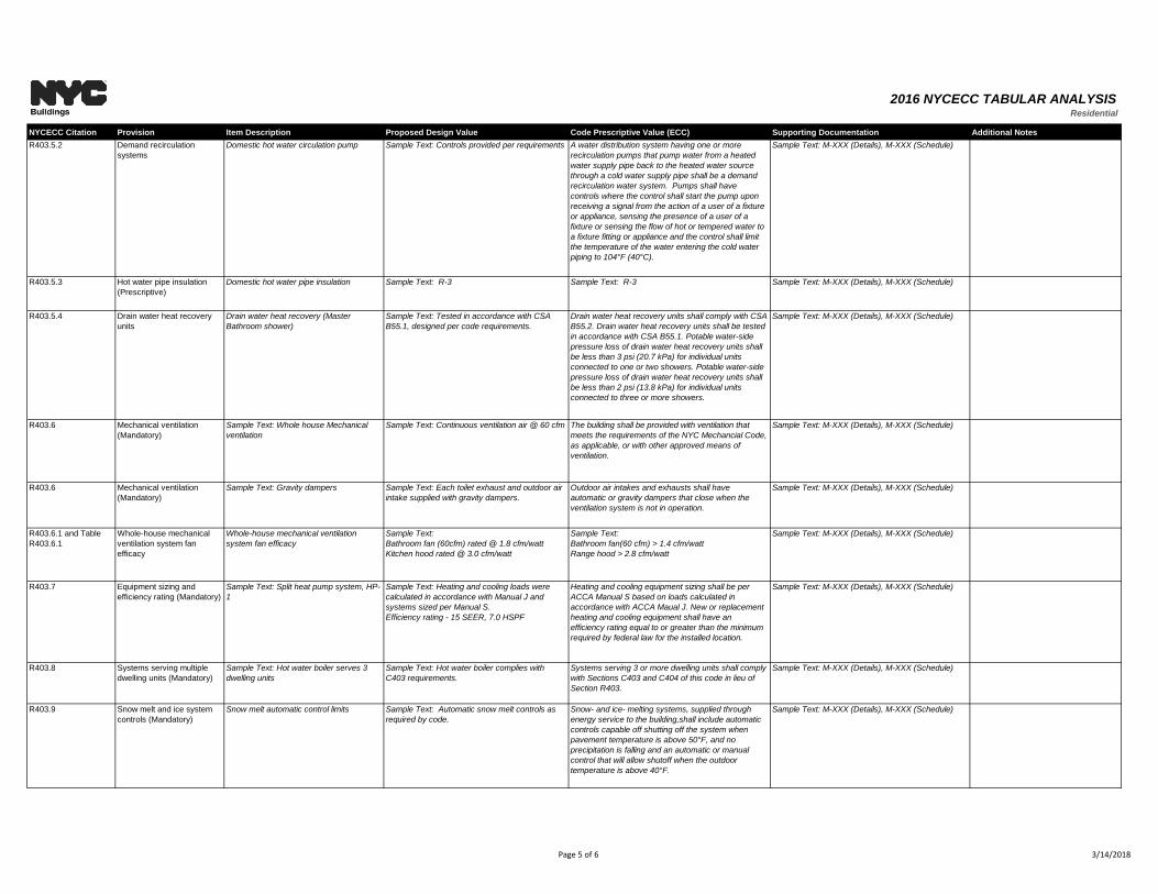
R403.5.2 Demand recirculation
systems
Domestic hot water circulation pump Sample Text: Controls provided per requirements A water distribution system having one or more
recirculation pumps that pump water from a heated
water supply pipe back to the heated water source
through a cold water supply pipe shall be a demand
recirculation water system. Pumps shall have
controls where the control shall start the pump upon
receiving a signal from the action of a user of a fixture
or appliance, sensing the presence of a user of a
fixture or sensing the flow of hot or tempered water to
a fixture fitting or appliance and the control shall limit
the temperature of the water entering the cold water
piping to 104°F (40°C).
Sample Text: M-XXX (Details), M-XXX (Schedule)
R403.5.3 Hot water pipe insulation
(Prescriptive)
Domestic hot water pipe insulation Sample Text: R-3 Sample Text: R-3 Sample Text: M-XXX (Details), M-XXX (Schedule)
R403.5.4 Drain water heat recovery
units
Drain water heat recovery (Master
Bathroom shower)
Sample Text: Tested in accordance with CSA
B55.1, designed per code requirements.
Drain water heat recovery units shall comply with CSA
B55.2. Drain water heat recovery units shall be tested
in accordance with CSA B55.1. Potable water-side
pressure loss of drain water heat recovery units shall
be less than 3 psi (20.7 kPa) for individual units
connected to one or two showers. Potable water-side
pressure loss of drain water heat recovery units shall
be less than 2 psi (13.8 kPa) for individual units
connected to three or more showers.
Sample Text: M-XXX (Details), M-XXX (Schedule)
R403.6 Mechanical ventilation
(Mandatory)
Sample Text: Whole house Mechanical
ventilation
Sample Text: Continuous ventilation air @ 60 cfm The building shall be provided with ventilation that
meets the requirements of the NYC Mechancial Code,
as applicable, or with other approved means of
ventilation.
Sample Text: M-XXX (Details), M-XXX (Schedule)
R403.6 Mechanical ventilation
(Mandatory)
Sample Text: Gravity dampers Sample Text: Each toilet exhaust and outdoor air
intake supplied with gravity dampers.
Outdoor air intakes and exhausts shall have
automatic or gravity dampers that close when the
ventilation system is not in operation.
Sample Text: M-XXX (Details), M-XXX (Schedule)
R403.6.1 and Table
R403.6.1
Whole-house mechanical
ventilation system fan
efficacy
Whole-house mechanical ventilation
system fan efficacy
Sample Text:
Bathroom fan (60cfm) rated @ 1.8 cfm/watt
Kitchen hood rated @ 3.0 cfm/watt
Sample Text:
Bathroom fan(60 cfm) > 1.4 cfm/watt
Range hood > 2.8 cfm/watt
Sample Text: M-XXX (Details), M-XXX (Schedule)
R403.7 Equipment sizing and
efficiency rating (Mandatory)
Sample Text: Split heat pump system, HP-
1
Sample Text: Heating and cooling loads were
calculated in accordance with Manual J and
systems sized per Manual S.
Efficiency rating - 15 SEER, 7.0 HSPF
Heating and cooling equipment sizing shall be per
ACCA Manual S based on loads calculated in
accordance with ACCA Maual J. New or replacement
heating and cooling equipment shall have an
efficiency rating equal to or greater than the minimum
required by federal law for the installed location.
Sample Text: M-XXX (Details), M-XXX (Schedule)
R403.8 Systems serving multiple
dwelling units (Mandatory)
Sample Text: Hot water boiler serves 3
dwelling units
Sample Text: Hot water boiler complies with
C403 requirements.
Systems serving 3 or more dwelling units shall comply
with Sections C403 and C404 of this code in lieu of
Section R403.
Sample Text: M-XXX (Details), M-XXX (Schedule)
R403.9 Snow melt and ice system
controls (Mandatory)
Snow melt automatic control limits Sample Text: Automatic snow melt controls as
required by code.
Snow- and ice- melting systems, supplied through
energy service to the building,shall include automatic
controls capable off shutting off the system when
pavement temperature is above 50°F, and no
precipitation is falling and an automatic or manual
control that will allow shutoff when the outdoor
temperature is above 40°F.
Sample Text: M-XXX (Details), M-XXX (Schedule)
Page 5 of 6 3/14/2018
2016 NYCECC TABULAR ANALYSISResidential
NYCECC Citation Provision Item Description Proposed Design Value Code Prescriptive Value (ECC) Supporting Documentation Additional Notes
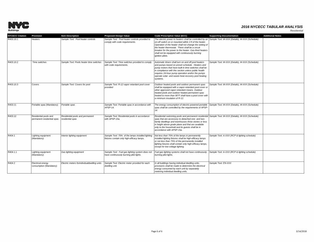
R403.10.1 Heaters Sample Text: Pool heater controls Sample Text: Pool heater controls provided to
comply with code requirements.
The electric power to heaters shall be controlled by an
on-off switch on or mounted within 3 ft of the heater.
Operation of the heater shall not change the setting of
the heater thermostat. There shall be a circuit
breaker for the power to the heater. Gas-fired heaters
shall not be equipped with continuously burning
ignition pilots.
Sample Text: M-XXX (Details), M-XXX (Schedule)
R403.10.2 Time switches Sample Text: Pools heater time switches Sample Text: Time switches provided to comply
with code requirements.
Automatic timers shall turn on and off pool heaters
and pumps based on preset schedule. Heaters and
pump motors that have built-in time switches shall be
in compliance with this section unless public health
requires 24-hour pump operation and/or the pumps
operate solar- and waste-heat-recovery pool heating
systems.
Sample Text: M-XXX (Details), M-XXX (Schedule)
R403.10.3 Covers Sample Text: Covers for pool Sample Text: R-12 vapor retardant pool cover
provided
Outdoor heated pools and outdoor permanent spas
shall be equipped with a vapor-retardant pool cover or
other approved vapor-retardant means. Outdoor
heated pools and outdoor heated permanent spas
heated to more than 90°F shall have a pool cover with
a minimum insulation of R-12.
Sample Text: M-XXX (Details), M-XXX (Schedule)
R403.11 Portable spas (Mandatory) Portable spas Sample Text: Portable spas in accordance with
APSP-14.
The energy consumption of electric-powered portable
spas shall be controlled by the requirements of APSP-
14.
Sample Text: M-XXX (Details), M-XXX (Schedule)
R403.12 Residential pools and
permanent residential spas
Residential pools and permanent
residential spas
Sample Text: Residential pools in accordance
with APSP-15a.
Residential swimming pools and permanent residential
spas that are accessory to detached one- and two-
family dwellings and townhouses three stories or less
in height above grade plane and that are available
only to the household and its guests shall be in
accordance with APSP-15a.
Sample Text: M-XXX (Details), M-XXX (Schedule)
R404.1 Lighting equipment
(Mandatory)
Interior lighting equipment Sample Text: 75% of the lamps installed lighting
fixtures contain only high-efficacy lamps.
Not less than 75% of the lamps in permanently
installed lighting fixtures shall be high-efficacy lamps
or not less than 75% of the permanently installed
lighting fixtures shall contain only high-efficacy lamps,
except for low-voltage lighting.
Sample Text: A-XXX (RCP & lighting schedule)
R404.1.1 Lighting equipment
(Mandatory)
Gas lighting equipment Sample Text: Fuel gas lighting system does not
have continuously burning pilot lights.
Fuel gas lighting systems shall not have continuously
burning pilot lights.
Sample Text: A-XXX (RCP & lighting schedule)
R404.2 Electrical energy
consumption (Mandatory)
Electric meters forindividualdwelling units Sample Text: Electric meter provided for each
dwelling unit.
In all buildings having individual dwelling units,
provisions shall be made to determine the electrical
energy consumed by each unit by separately
metering individual dwelling units.
Sample Text: EN-XXX
Page 6 of 6 3/14/2018
2016 NYCECC TABULAR ANALYSISCommercial - Envelope
NYCECC Citation Provision Item Description Proposed Design Value Code Prescriptive Value (ECC) Supporting Documentation
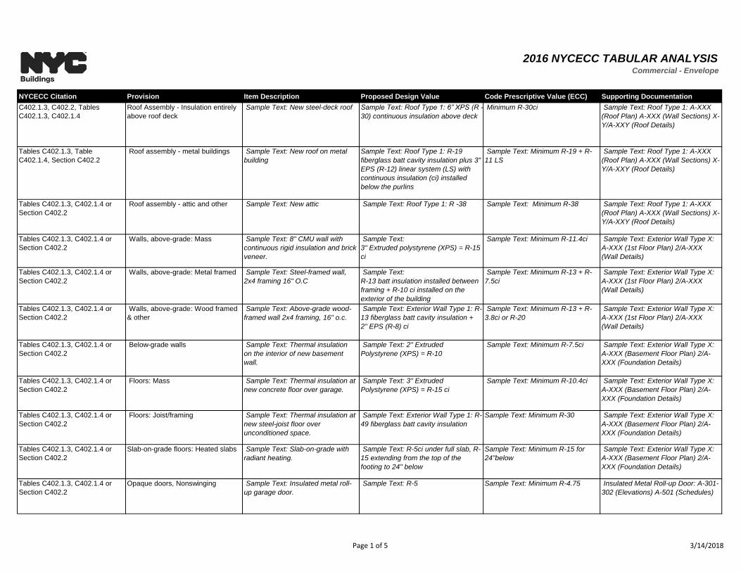
C402.1.3, C402.2, Tables
C402.1.3, C402.1.4
Roof Assembly - Insulation entirely
above roof deck
Sample Text: New steel-deck roof Sample Text: Roof Type 1: 6” XPS (R -
30) continuous insulation above deck
Minimum R-30ci Sample Text: Roof Type 1: A-XXX
(Roof Plan) A-XXX (Wall Sections) X-
Y/A-XXY (Roof Details)
Tables C402.1.3, Table
C402.1.4, Section C402.2
Roof assembly - metal buildings Sample Text: New roof on metal
building
Sample Text: Roof Type 1: R-19
fiberglass batt cavity insulation plus 3"
EPS (R-12) linear system (LS) with
continuous insulation (ci) installed
below the purlins
Sample Text: Minimum R-19 + R-
11 LS
Sample Text: Roof Type 1: A-XXX
(Roof Plan) A-XXX (Wall Sections) X-
Y/A-XXY (Roof Details)
Tables C402.1.3, C402.1.4 or
Section C402.2
Roof assembly - attic and other Sample Text: New attic Sample Text: Roof Type 1: R -38 Sample Text: Minimum R-38 Sample Text: Roof Type 1: A-XXX
(Roof Plan) A-XXX (Wall Sections) X-
Y/A-XXY (Roof Details)
Tables C402.1.3, C402.1.4 or
Section C402.2
Walls, above-grade: Mass Sample Text: 8" CMU wall with
continuous rigid insulation and brick
veneer.
Sample Text:
3" Extruded polystyrene (XPS) = R-15
ci
Sample Text: Minimum R-11.4ci Sample Text: Exterior Wall Type X:
A-XXX (1st Floor Plan) 2/A-XXX
(Wall Details)
Tables C402.1.3, C402.1.4 or
Section C402.2
Walls, above-grade: Metal framed Sample Text: Steel-framed wall,
2x4 framing 16" O.C
Sample Text:
R-13 batt insulation installed between
framing + R-10 ci installed on the
exterior of the building
Sample Text: Minimum R-13 + R-
7.5ci
Sample Text: Exterior Wall Type X:
A-XXX (1st Floor Plan) 2/A-XXX
(Wall Details)
Tables C402.1.3, C402.1.4 or
Section C402.2
Walls, above-grade: Wood framed
& other
Sample Text: Above-grade wood-
framed wall 2x4 framing, 16" o.c.
Sample Text: Exterior Wall Type 1: R-
13 fiberglass batt cavity insulation +
2" EPS (R-8) ci
Sample Text: Minimum R-13 + R-
3.8ci or R-20
Sample Text: Exterior Wall Type X:
A-XXX (1st Floor Plan) 2/A-XXX
(Wall Details)
Tables C402.1.3, C402.1.4 or
Section C402.2
Below-grade walls Sample Text: Thermal insulation
on the interior of new basement
wall.
Sample Text: 2" Extruded
Polystyrene (XPS) = R-10
Sample Text: Minimum R-7.5ci Sample Text: Exterior Wall Type X:
A-XXX (Basement Floor Plan) 2/A-
XXX (Foundation Details)
Tables C402.1.3, C402.1.4 or
Section C402.2
Floors: Mass Sample Text: Thermal insulation at
new concrete floor over garage.
Sample Text: 3" Extruded
Polystyrene (XPS) = R-15 ci
Sample Text: Minimum R-10.4ci Sample Text: Exterior Wall Type X:
A-XXX (Basement Floor Plan) 2/A-
XXX (Foundation Details)
Tables C402.1.3, C402.1.4 or
Section C402.2
Floors: Joist/framing Sample Text: Thermal insulation at
new steel-joist floor over
unconditioned space.
Sample Text: Exterior Wall Type 1: R-
49 fiberglass batt cavity insulation
Sample Text: Minimum R-30 Sample Text: Exterior Wall Type X:
A-XXX (Basement Floor Plan) 2/A-
XXX (Foundation Details)
Tables C402.1.3, C402.1.4 or
Section C402.2
Slab-on-grade floors: Heated slabs Sample Text: Slab-on-grade with
radiant heating.
Sample Text: R-5ci under full slab, R-
15 extending from the top of the
footing to 24" below
Sample Text: Minimum R-15 for
24"below
Sample Text: Exterior Wall Type X:
A-XXX (Basement Floor Plan) 2/A-
XXX (Foundation Details)
Tables C402.1.3, C402.1.4 or
Section C402.2
Opaque doors, Nonswinging Sample Text: Insulated metal roll-
up garage door.
Sample Text: R-5 Sample Text: Minimum R-4.75 Insulated Metal Roll-up Door: A-301-
302 (Elevations) A-501 (Schedules)
Page 1 of 5 3/14/2018
2016 NYCECC TABULAR ANALYSISCommercial - Envelope
NYCECC Citation Provision Item Description Proposed Design Value Code Prescriptive Value (ECC) Supporting Documentation
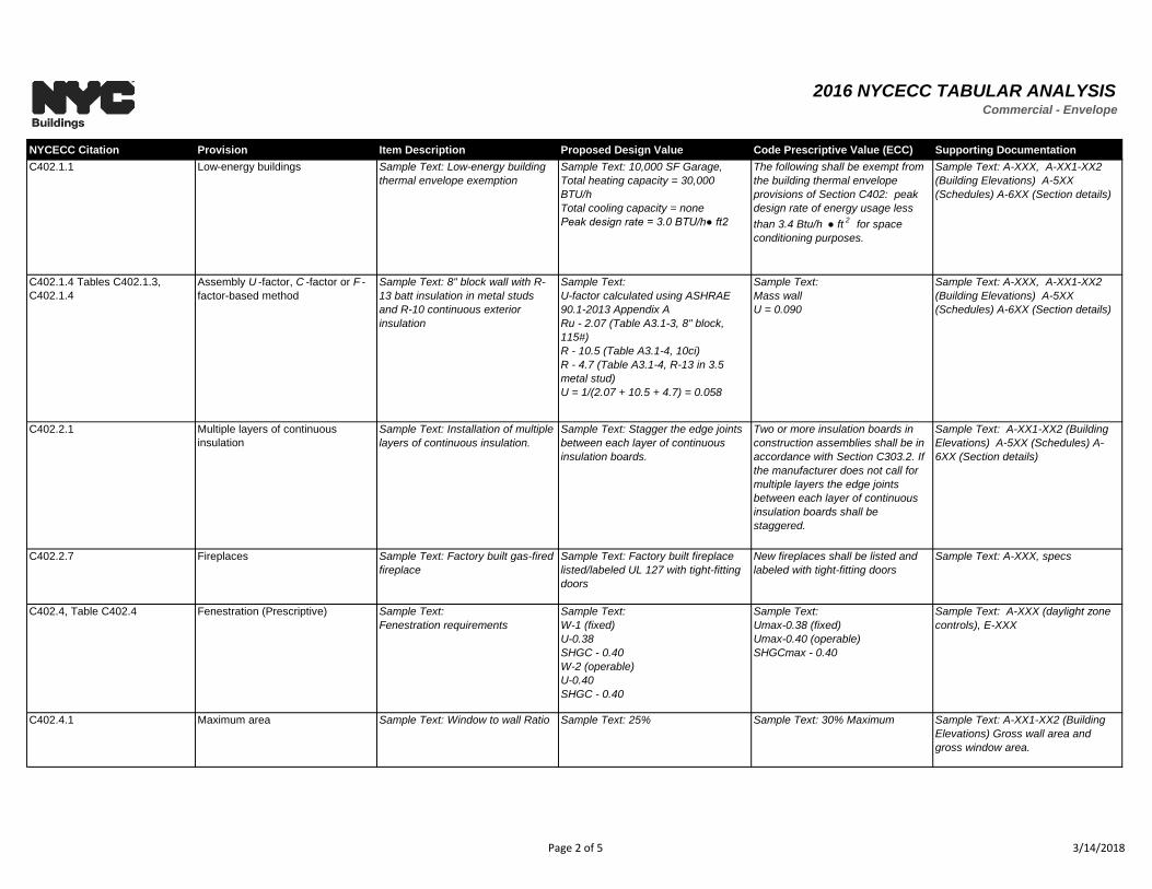
C402.1.1 Low-energy buildings Sample Text: Low-energy building
thermal envelope exemption
Sample Text: 10,000 SF Garage,
Total heating capacity = 30,000
BTU/h
Total cooling capacity = none
Peak design rate = 3.0 BTU/h● ft2
The following shall be exempt from
the building thermal envelope
provisions of Section C402: peak
design rate of energy usage less
than 3.4 Btu/h ● ft2
for space
conditioning purposes.
Sample Text: A-XXX, A-XX1-XX2
(Building Elevations) A-5XX
(Schedules) A-6XX (Section details)
C402.1.4 Tables C402.1.3,
C402.1.4
Assembly U -factor, C -factor or F -
factor-based method
Sample Text: 8" block wall with R-
13 batt insulation in metal studs
and R-10 continuous exterior
insulation
Sample Text:
U-factor calculated using ASHRAE
90.1-2013 Appendix A
Ru - 2.07 (Table A3.1-3, 8" block,
115#)
R - 10.5 (Table A3.1-4, 10ci)
R - 4.7 (Table A3.1-4, R-13 in 3.5
metal stud)
U = 1/(2.07 + 10.5 + 4.7) = 0.058
Sample Text:
Mass wall
U = 0.090
Sample Text: A-XXX, A-XX1-XX2
(Building Elevations) A-5XX
(Schedules) A-6XX (Section details)
C402.2.1 Multiple layers of continuous
insulation
Sample Text: Installation of multiple
layers of continuous insulation.
Sample Text: Stagger the edge joints
between each layer of continuous
insulation boards.
Two or more insulation boards in
construction assemblies shall be in
accordance with Section C303.2. If
the manufacturer does not call for
multiple layers the edge joints
between each layer of continuous
insulation boards shall be
staggered.
Sample Text: A-XX1-XX2 (Building
Elevations) A-5XX (Schedules) A-
6XX (Section details)
C402.2.7 Fireplaces Sample Text: Factory built gas-fired
fireplace
Sample Text: Factory built fireplace
listed/labeled UL 127 with tight-fitting
doors
New fireplaces shall be listed and
labeled with tight-fitting doors
Sample Text: A-XXX, specs
C402.4, Table C402.4 Fenestration (Prescriptive) Sample Text:
Fenestration requirements
Sample Text:
W-1 (fixed)
U-0.38
SHGC - 0.40
W-2 (operable)
U-0.40
SHGC - 0.40
Sample Text:
Umax-0.38 (fixed)
Umax-0.40 (operable)
SHGCmax - 0.40
Sample Text: A-XXX (daylight zone
controls), E-XXX
C402.4.1 Maximum area Sample Text: Window to wall Ratio Sample Text: 25% Sample Text: 30% Maximum Sample Text: A-XX1-XX2 (Building
Elevations) Gross wall area and
gross window area.
Page 2 of 5 3/14/2018
2016 NYCECC TABULAR ANALYSISCommercial - Envelope
NYCECC Citation Provision Item Description Proposed Design Value Code Prescriptive Value (ECC) Supporting Documentation
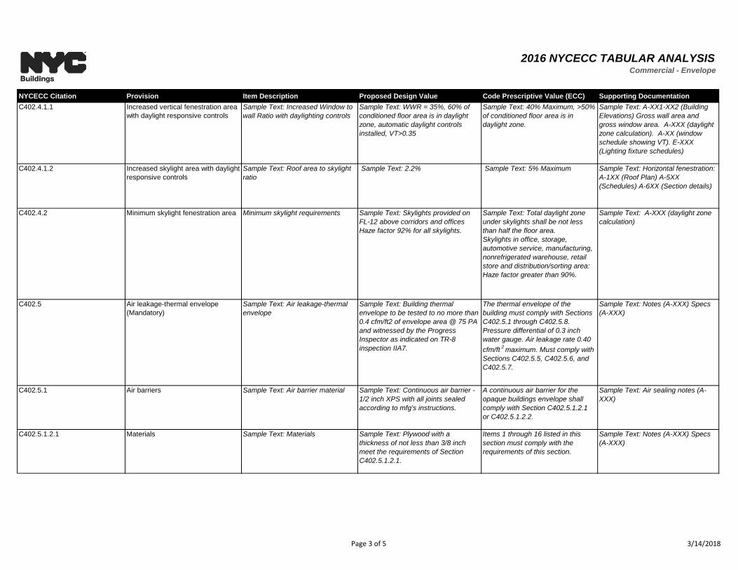
C402.4.1.1 Increased vertical fenestration area
with daylight responsive controls
Sample Text: Increased Window to
wall Ratio with daylighting controls
Sample Text: WWR = 35%, 60% of
conditioned floor area is in daylight
zone, automatic daylight controls
installed, VT>0.35
Sample Text: 40% Maximum, >50%
of conditioned floor area is in
daylight zone.
Sample Text: A-XX1-XX2 (Building
Elevations) Gross wall area and
gross window area. A-XXX (daylight
zone calculation). A-XX (window
schedule showing VT). E-XXX
(Lighting fixture schedules)
C402.4.1.2 Increased skylight area with daylight
responsive controls
Sample Text: Roof area to skylight
ratio
Sample Text: 2.2% Sample Text: 5% Maximum Sample Text: Horizontal fenestration:
A-1XX (Roof Plan) A-5XX
(Schedules) A-6XX (Section details)
C402.4.2 Minimum skylight fenestration area Minimum skylight requirements Sample Text: Skylights provided on
FL-12 above corridors and offices
Haze factor 92% for all skylights.
Sample Text: Total daylight zone
under skylights shall be not less
than half the floor area.
Skylights in office, storage,
automotive service, manufacturing,
nonrefrigerated warehouse, retail
store and distribution/sorting area:
Haze factor greater than 90%.
Sample Text: A-XXX (daylight zone
calculation)
C402.5 Air leakage-thermal envelope
(Mandatory)
Sample Text: Air leakage-thermal
envelope
Sample Text: Building thermal
envelope to be tested to no more than
0.4 cfm/ft2 of envelope area @ 75 PA
and witnessed by the Progress
Inspector as indicated on TR-8
inspection IIA7.
The thermal envelope of the
building must comply with Sections
C402.5.1 through C402.5.8.
Pressure differential of 0.3 inch
water gauge. Air leakage rate 0.40
cfm/ft2maximum. Must comply with
Sections C402.5.5, C402.5.6, and
C402.5.7.
Sample Text: Notes (A-XXX) Specs
(A-XXX)
C402.5.1 Air barriers Sample Text: Air barrier material Sample Text: Continuous air barrier -
1/2 inch XPS with all joints sealed
according to mfg's instructions.
A continuous air barrier for the
opaque buildings envelope shall
comply with Section C402.5.1.2.1
or C402.5.1.2.2.
Sample Text: Air sealing notes (A-
XXX)
C402.5.1.2.1 Materials Sample Text: Materials Sample Text: Plywood with a
thickness of not less than 3/8 inch
meet the requirements of Section
C402.5.1.2.1.
Items 1 through 16 listed in this
section must comply with the
requirements of this section.
Sample Text: Notes (A-XXX) Specs
(A-XXX)
Page 3 of 5 3/14/2018
2016 NYCECC TABULAR ANALYSISCommercial - Envelope
NYCECC Citation Provision Item Description Proposed Design Value Code Prescriptive Value (ECC) Supporting Documentation
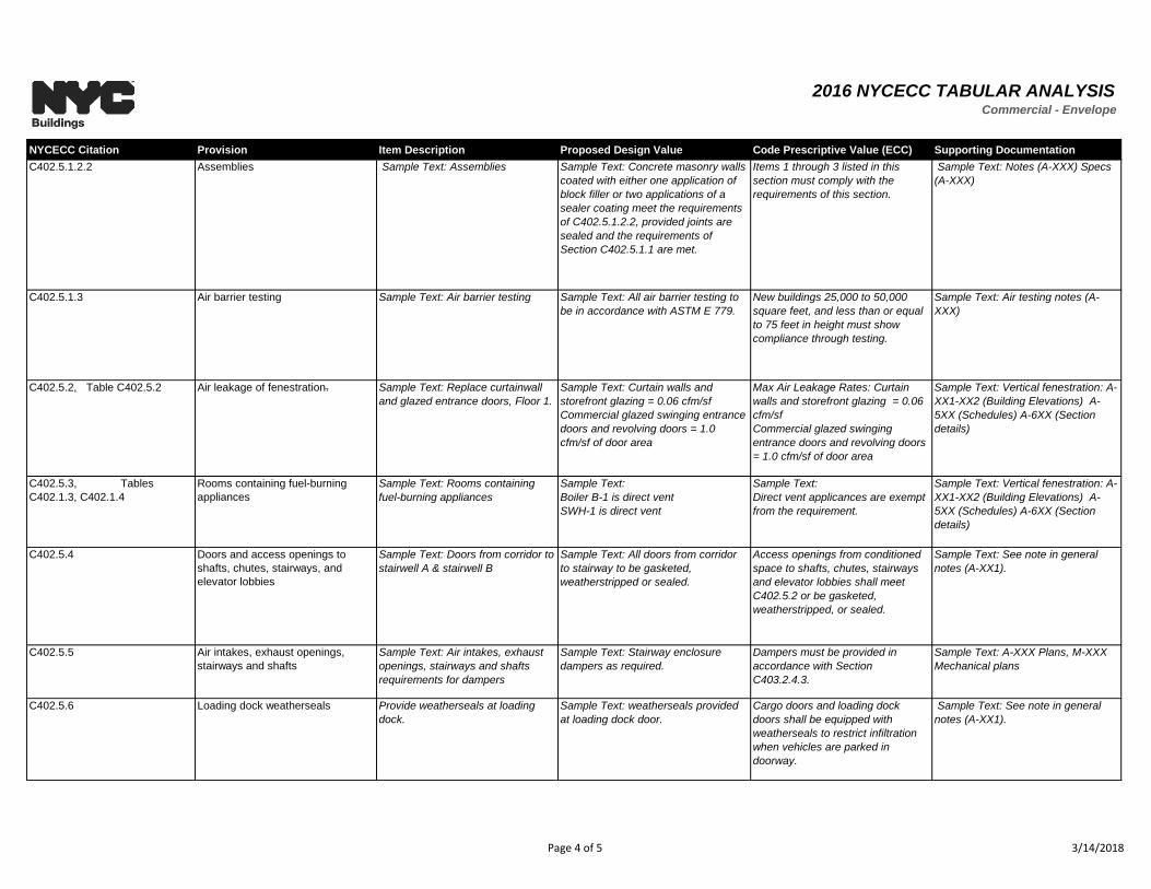
C402.5.1.2.2 Assemblies Sample Text: Assemblies Sample Text: Concrete masonry walls
coated with either one application of
block filler or two applications of a
sealer coating meet the requirements
of C402.5.1.2.2, provided joints are
sealed and the requirements of
Section C402.5.1.1 are met.
Items 1 through 3 listed in this
section must comply with the
requirements of this section.
Sample Text: Notes (A-XXX) Specs
(A-XXX)
C402.5.1.3 Air barrier testing Sample Text: Air barrier testing Sample Text: All air barrier testing to
be in accordance with ASTM E 779.
New buildings 25,000 to 50,000
square feet, and less than or equal
to 75 feet in height must show
compliance through testing.
Sample Text: Air testing notes (A-
XXX)
C402.5.2, Table C402.5.2 Air leakage of fenestration. Sample Text: Replace curtainwall
and glazed entrance doors, Floor 1.
Sample Text: Curtain walls and
storefront glazing = 0.06 cfm/sf
Commercial glazed swinging entrance
doors and revolving doors = 1.0
cfm/sf of door area
Max Air Leakage Rates: Curtain
walls and storefront glazing = 0.06
cfm/sf
Commercial glazed swinging
entrance doors and revolving doors
= 1.0 cfm/sf of door area
Sample Text: Vertical fenestration: A-
XX1-XX2 (Building Elevations) A-
5XX (Schedules) A-6XX (Section
details)
C402.5.3, Tables
C402.1.3, C402.1.4
Rooms containing fuel-burning
appliances
Sample Text: Rooms containing
fuel-burning appliances
Sample Text:
Boiler B-1 is direct vent
SWH-1 is direct vent
Sample Text:
Direct vent applicances are exempt
from the requirement.
Sample Text: Vertical fenestration: A-
XX1-XX2 (Building Elevations) A-
5XX (Schedules) A-6XX (Section
details)
C402.5.4 Doors and access openings to
shafts, chutes, stairways, and
elevator lobbies
Sample Text: Doors from corridor to
stairwell A & stairwell B
Sample Text: All doors from corridor
to stairway to be gasketed,
weatherstripped or sealed.
Access openings from conditioned
space to shafts, chutes, stairways
and elevator lobbies shall meet
C402.5.2 or be gasketed,
weatherstripped, or sealed.
Sample Text: See note in general
notes (A-XX1).
C402.5.5 Air intakes, exhaust openings,
stairways and shafts
Sample Text: Air intakes, exhaust
openings, stairways and shafts
requirements for dampers
Sample Text: Stairway enclosure
dampers as required.
Dampers must be provided in
accordance with Section
C403.2.4.3.
Sample Text: A-XXX Plans, M-XXX
Mechanical plans
C402.5.6 Loading dock weatherseals Provide weatherseals at loading
dock.
Sample Text: weatherseals provided
at loading dock door.
Cargo doors and loading dock
doors shall be equipped with
weatherseals to restrict infiltration
when vehicles are parked in
doorway.
Sample Text: See note in general
notes (A-XX1).
Page 4 of 5 3/14/2018
2016 NYCECC TABULAR ANALYSISCommercial - Envelope
NYCECC Citation Provision Item Description Proposed Design Value Code Prescriptive Value (ECC) Supporting Documentation
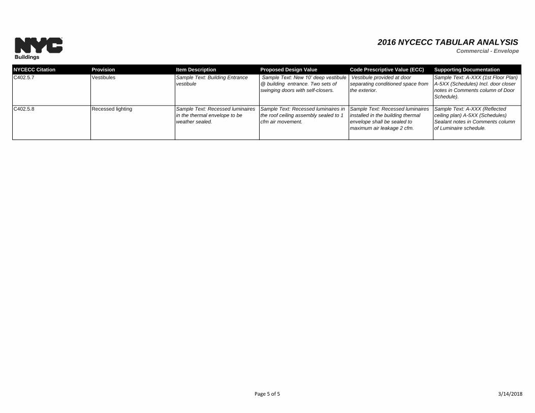
C402.5.7 Vestibules Sample Text: Building Entrance
vestibule
Sample Text: New 10’ deep vestibule
@ building entrance. Two sets of
swinging doors with self-closers.
Vestibule provided at door
separating conditioned space from
the exterior.
Sample Text: A-XXX (1st Floor Plan)
A-5XX (Schedules) Incl. door closer
notes in Comments column of Door
Schedule).
C402.5.8 Recessed lighting Sample Text: Recessed luminaires
in the thermal envelope to be
weather sealed.
Sample Text: Recessed luminaires in
the roof ceiling assembly sealed to 1
cfm air movement.
Sample Text: Recessed luminaires
installed in the building thermal
envelope shall be sealed to
maximum air leakage 2 cfm.
Sample Text: A-XXX (Reflected
ceiling plan) A-5XX (Schedules)
Sealant notes in Comments column
of Luminaire schedule.
Page 5 of 5 3/14/2018
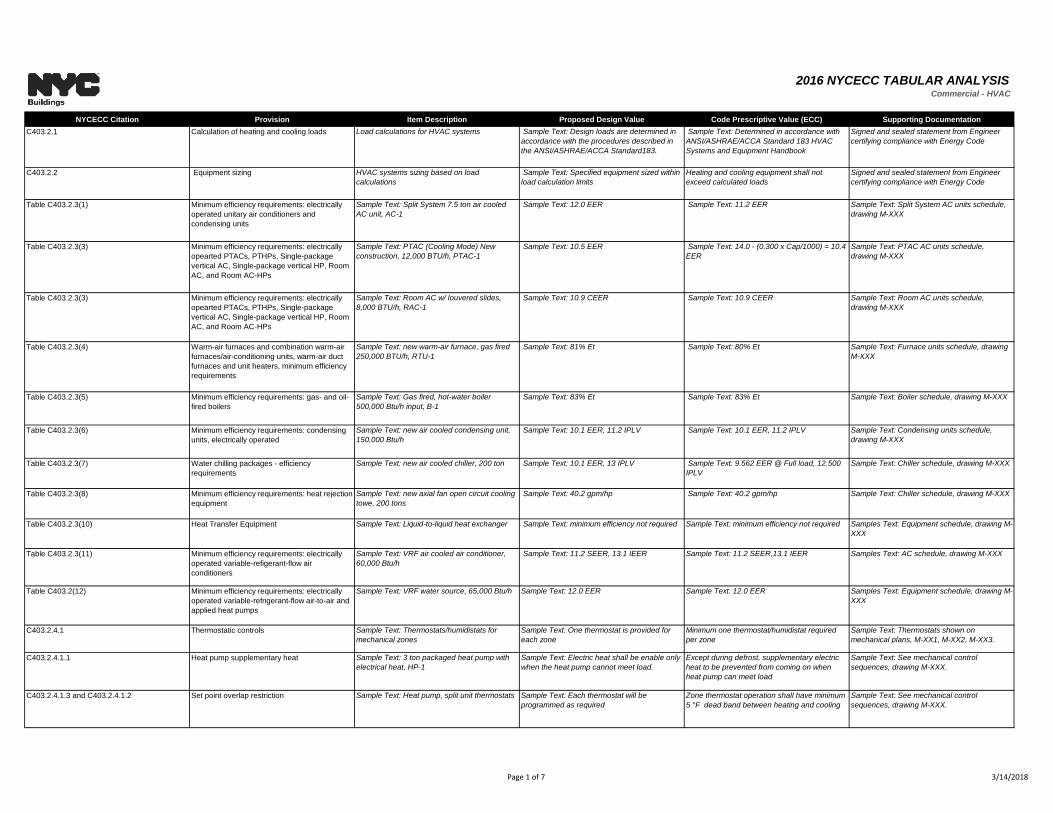
2016 NYCECC TABULAR ANALYSISCommercial - HVAC
NYCECC Citation Provision Item Description Proposed Design Value Code Prescriptive Value (ECC) Supporting Documentation
C403.2.1 Calculation of heating and cooling loads Load calculations for HVAC systems Sample Text: Design loads are determined in
accordance with the procedures described in
the ANSI/ASHRAE/ACCA Standard183.
Sample Text: Determined in accordance with
ANSI/ASHRAE/ACCA Standard 183 HVAC
Systems and Equipment Handbook
Signed and sealed statement from Engineer
certifying compliance with Energy Code
C403.2.2 Equipment sizing HVAC systems sizing based on load
calculations
Sample Text: Specified equipment sized within
load calculation limits
Heating and cooling equipment shall not
exceed calculated loads
Signed and sealed statement from Engineer
certifying compliance with Energy Code
Table C403.2.3(1) Minimum efficiency requirements: electrically
operated unitary air conditioners and
condensing units
Sample Text: Split System 7.5 ton air cooled
AC unit, AC-1
Sample Text: 12.0 EER Sample Text: 11.2 EER Sample Text: Split System AC units schedule,
drawing M-XXX
Table C403.2.3(3) Minimum efficiency requirements: electrically
opearted PTACs, PTHPs, Single-package
vertical AC, Single-package vertical HP, Room
AC, and Room AC-HPs
Sample Text: PTAC (Cooling Mode) New
construction, 12,000 BTU/h, PTAC-1
Sample Text: 10.5 EER Sample Text: 14.0 - (0.300 x Cap/1000) = 10.4
EER
Sample Text: PTAC AC units schedule,
drawing M-XXX
Table C403.2.3(3) Minimum efficiency requirements: electrically
opearted PTACs, PTHPs, Single-package
vertical AC, Single-package vertical HP, Room
AC, and Room AC-HPs
Sample Text: Room AC w/ louvered slides,
8,000 BTU/h, RAC-1
Sample Text: 10.9 CEER Sample Text: 10.9 CEER Sample Text: Room AC units schedule,
drawing M-XXX
Table C403.2.3(4) Warm-air furnaces and combination warm-air
furnaces/air-conditioning units, warm-air duct
furnaces and unit heaters, minimum efficiency
requirements
Sample Text: new warm-air furnace, gas fired
250,000 BTU/h, RTU-1
Sample Text: 81% Et Sample Text: 80% Et Sample Text: Furnace units schedule, drawing
M-XXX
Table C403.2.3(5) Minimum efficiency requirements: gas- and oil-
fired boilers
Sample Text: Gas fired, hot-water boiler
500,000 Btu/h input, B-1
Sample Text: 83% Et Sample Text: 83% Et Sample Text: Boiler schedule, drawing M-XXX
Table C403.2.3(6) Minimum efficiency requirements: condensing
units, electrically operated
Sample Text: new air cooled condensing unit,
150,000 Btu/h
Sample Text: 10.1 EER, 11.2 IPLV Sample Text: 10.1 EER, 11.2 IPLV Sample Text: Condensing units schedule,
drawing M-XXX
Table C403.2.3(7) Water chilling packages - efficiency
requirements
Sample Text: new air cooled chiller, 200 ton Sample Text: 10.1 EER, 13 IPLV Sample Text: 9.562 EER @ Full load, 12.500
IPLV
Sample Text: Chiller schedule, drawing M-XXX
Table C403.2.3(8) Minimum efficiency requirements: heat rejection
equipment
Sample Text: new axial fan open circuit cooling
towe, 200 tons
Sample Text: 40.2 gpm/hp Sample Text: 40.2 gpm/hp Sample Text: Chiller schedule, drawing M-XXX
Table C403.2.3(10) Heat Transfer Equipment Sample Text: Liquid-to-liquid heat exchanger Sample Text: minimum efficiency not required Sample Text: minimum efficiency not required Samples Text: Equipment schedule, drawing M-
XXX
Table C403.2.3(11) Minimum efficiency requirements: electrically
operated variable-refigerant-flow air
conditioners
Sample Text: VRF air cooled air conditioner,
60,000 Btu/h
Sample Text: 11.2 SEER, 13.1 IEER Sample Text: 11.2 SEER,13.1 IEER Samples Text: AC schedule, drawing M-XXX
Table C403.2(12) Minimum efficiency requirements: electrically
operated variable-refrigerant-flow air-to-air and
applied heat pumps
Sample Text: VRF water source, 65,000 Btu/h Sample Text: 12.0 EER Sample Text: 12.0 EER Samples Text: Equipment schedule, drawing M-
XXX
C403.2.4.1 Thermostatic controls Sample Text: Thermostats/humidistats for
mechanical zones
Sample Text: One thermostat is provided for
each zone
Minimum one thermostat/humidistat required
per zone
Sample Text: Thermostats shown on
mechanical plans, M-XX1, M-XX2, M-XX3.
C403.2.4.1.1 Heat pump supplementary heat Sample Text: 3 ton packaged heat pump with
electrical heat, HP-1
Sample Text: Electric heat shall be enable only
when the heat pump cannot meet load.
Except during defrost, supplementary electric
heat to be prevented from coming on when
heat pump can meet load
Sample Text: See mechanical control
sequences, drawing M-XXX.
C403.2.4.1.3 and C403.2.4.1.2 Set point overlap restriction Sample Text: Heat pump, split unit thermostats Sample Text: Each thermostat will be
programmed as required
Zone thermostat operation shall have minimum
5 °F dead band between heating and cooling
Sample Text: See mechanical control
sequences, drawing M-XXX.
Page 1 of 7 3/14/2018
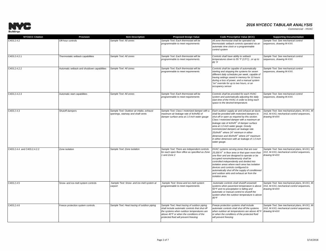
2016 NYCECC TABULAR ANALYSISCommercial - HVAC
NYCECC Citation Provision Item Description Proposed Design Value Code Prescriptive Value (ECC) Supporting Documentation
C403.2.4.2 Off-hour controls Sample Text: All zones Sample Text: Each thermostat will be
programmable to meet requirements
All zone thermostat shall be operated via
thermostatic setback controls operated via an
automatic time clock or a programmable
control system
Sample Text: See mechanical control
sequences, drawing M-XXX.
C403.2.4.2.1 Thermostatic setback capabilities Sample Text: All zones Sample Text: Each thermostat will be
programmable to meet requirements
Controls shall have ability to setback
temperatures down to 55 °F (13°C) , or up to
85 °F
Sample Text: See mechanical control
sequences, drawing M-XXX.
C403.2.4.2.2 Automatic setback and shutdown capabilities Sample Text: All zones Sample Text: Each thermostat will be
programmable to meet requirements
Controls shall be capable of automatically
starting and stopping the systems for seven
different daily schedules per week, capable of
having settings saved in memory for 10 hours
during a loss of power, and a manual system
"on" override for up to two hours, or an
occupancy sensor
Sample Text: See mechanical control
sequences, drawing M-XXX.
C403.2.4.2.3 Automatic start capabilities Sample Text: All zones Sample Text: Each thermostat will be
programmable to meet requirements
Controls shall be provided for each HVAC
system and automatically adjusting the daily
start time of the HVAC in order to bring each
space to the desired temperature.
Sample Text: See mechanical control
sequences, drawing M-XXX.
C403.2.4.3 Shutoff dampers Sample Text: Outdoor air intake, exhaust
openings, stairway and shaft vents
Sample Text: Class I motorized damper with a
maximum air leakage rate of 4cfm/ft2 of
damper surface area at 1.0 inch water gauge
Each outdoor supply air and exhaust air ducts
shall be provided with motorized dampers to
shut off or open as required by this section.
Class I motorized damper with a maximum air
leakage rate of 4cfm/ft2
of damper surface
area at 1.0 inch water gauge. Gravity
nonmotorized dampers air leakage rate
20cfm/ft2
where 24" minimum in either
dimension and 40cfm/ft2
where 24" maximum
in either dimension with air leakage of 1.0 inch
water gauge.
Sample Text: See mechanical plans, M-XX1, M-
XX2, M-XX3, mechanical control sequences,
drawing M-4XX
C403.2.4.4 and C403.2.4.2.2 Zone isolation Sample Text: Zone isolation Sample Text: There are independent controls
for each open floor office as specified as Zone
1 and Zone 2
HVAC systems serving zones that are over
25,000 ft2 in floor area or that span more than
one floor and are designed to operate or be
occupied nonsimultaneously shall be
controlled independently and divided into
isolation areas where each area has isolation
devices and controls configured to
automatically shut off the supply of conditioned
and outdoor airto and exhaust air from the
isolation area.
Sample Text: See mechanical plans, M-XX1, M-
XX2, M-XX3, mechanical control sequences,
drawing M-4XX
C403.2.4.5 Snow- and ice-melt system controls Sample Text: Snow- and ice-melt system at
carport
Sample Text: Snow-and ice-melt system
programmable to meet requirements
Automatic controls shall shutoff snowmelt
systems when pavement temperature is above
50°F and no precipitation is falling and
automatic or manual control to shutoff the
system when the outdoor temperature is above
40°F
Sample Text: See mechanical plans, M-XX1, M-
XX2, M-XX3, mechanical control sequences,
drawing M-4XX
C403.2.4.6 Freeze protection system controls Sample Text: Heat tracing of outdoor piping Sample Text: Heat tracing of outdoor piping
shall include automatic controls that shut off
the systems when outdoor temperatures are
above 40°F or when the conditions of the
protected fluid will prevent freezing
Freeze protection systems shall include
automatic controls shall shut off the systems
when outdoor air temperatures are above 40°F
or when the conditions of the protected fluid
will prevent freezing
Sample Text: See mechanical plans, M-XX1, M-
XX2, M-XX3, mechanical control sequences,
drawing M-4XX
Page 2 of 7 3/14/2018
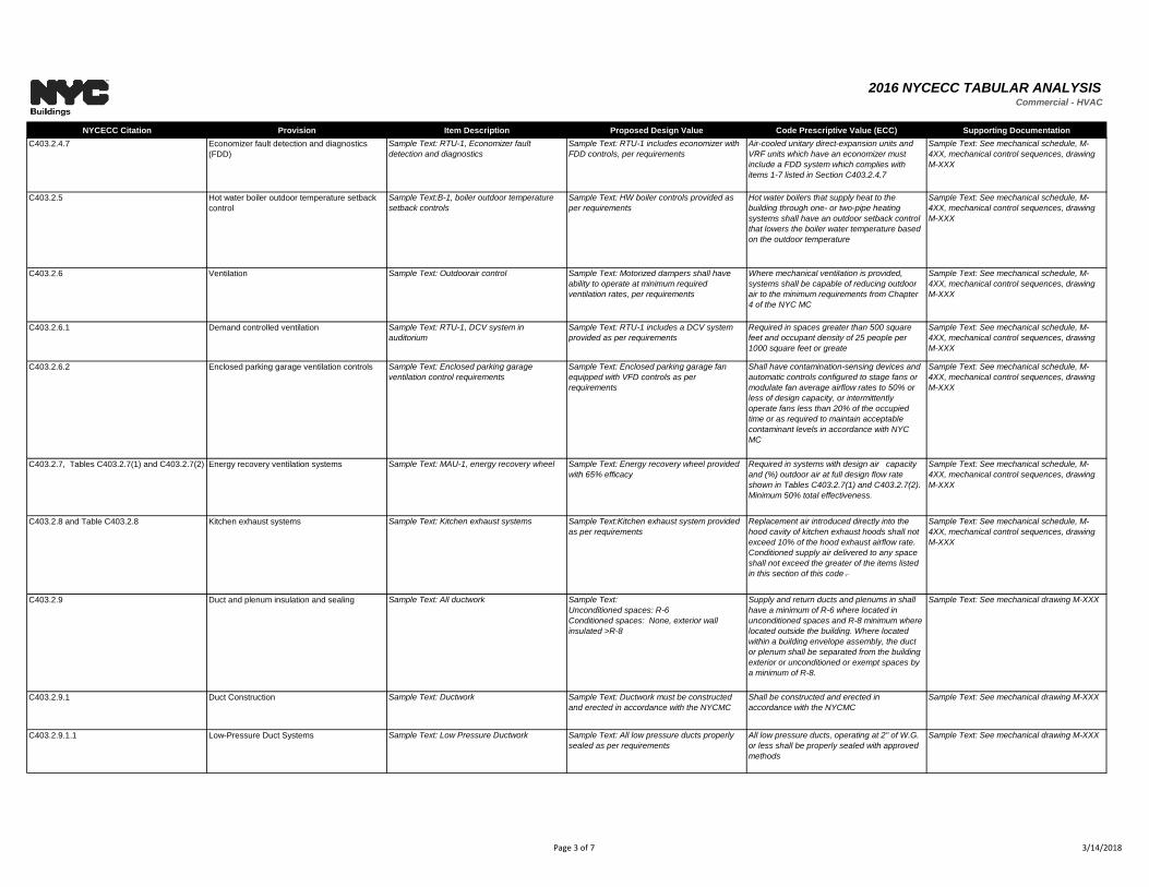
2016 NYCECC TABULAR ANALYSISCommercial - HVAC
NYCECC Citation Provision Item Description Proposed Design Value Code Prescriptive Value (ECC) Supporting Documentation
C403.2.4.7 Economizer fault detection and diagnostics
(FDD)
Sample Text: RTU-1, Economizer fault
detection and diagnostics
Sample Text: RTU-1 includes economizer with
FDD controls, per requirements
Air-cooled unitary direct-expansion units and
VRF units which have an economizer must
include a FDD system which complies with
items 1-7 listed in Section C403.2.4.7
Sample Text: See mechanical schedule, M-
4XX, mechanical control sequences, drawing
M-XXX
C403.2.5 Hot water boiler outdoor temperature setback
control
Sample Text:B-1, boiler outdoor temperature
setback controls
Sample Text: HW boiler controls provided as
per requirements
Hot water boilers that supply heat to the
building through one- or two-pipe heating
systems shall have an outdoor setback control
that lowers the boiler water temperature based
on the outdoor temperature
Sample Text: See mechanical schedule, M-
4XX, mechanical control sequences, drawing
M-XXX
C403.2.6 Ventilation Sample Text: Outdoorair control Sample Text: Motorized dampers shall have
ability to operate at minimum required
ventilation rates, per requirements
Where mechanical ventilation is provided,
systems shall be capable of reducing outdoor
air to the minimum requirements from Chapter
4 of the NYC MC
Sample Text: See mechanical schedule, M-
4XX, mechanical control sequences, drawing
M-XXX
C403.2.6.1 Demand controlled ventilation Sample Text: RTU-1, DCV system in
auditorium
Sample Text: RTU-1 includes a DCV system
provided as per requirements
Required in spaces greater than 500 square
feet and occupant density of 25 people per
1000 square feet or greate
Sample Text: See mechanical schedule, M-
4XX, mechanical control sequences, drawing
M-XXX
C403.2.6.2 Enclosed parking garage ventilation controls Sample Text: Enclosed parking garage
ventilation control requirements
Sample Text: Enclosed parking garage fan
equipped with VFD controls as per
requirements
Shall have contamination-sensing devices and
automatic controls configured to stage fans or
modulate fan average airflow rates to 50% or
less of design capacity, or intermittently
operate fans less than 20% of the occupied
time or as required to maintain acceptable
contaminant levels in accordance with NYC
MC
Sample Text: See mechanical schedule, M-
4XX, mechanical control sequences, drawing
M-XXX
C403.2.7, Tables C403.2.7(1) and C403.2.7(2) Energy recovery ventilation systems Sample Text: MAU-1, energy recovery wheel Sample Text: Energy recovery wheel provided
with 65% efficacy
Required in systems with design air capacity
and (%) outdoor air at full design flow rate
shown in Tables C403.2.7(1) and C403.2.7(2).
Minimum 50% total effectiveness.
Sample Text: See mechanical schedule, M-
4XX, mechanical control sequences, drawing
M-XXX
C403.2.8 and Table C403.2.8 Kitchen exhaust systems Sample Text: Kitchen exhaust systems Sample Text:Kitchen exhaust system provided
as per requirements
Replacement air introduced directly into the
hood cavity of kitchen exhaust hoods shall not
exceed 10% of the hood exhaust airflow rate.
Conditioned supply air delivered to any space
shall not exceed the greater of the items listed
in this section of this code .
Sample Text: See mechanical schedule, M-
4XX, mechanical control sequences, drawing
M-XXX
C403.2.9 Duct and plenum insulation and sealing Sample Text: All ductwork Sample Text:
Unconditioned spaces: R-6
Conditioned spaces: None, exterior wall
insulated >R-8
Supply and return ducts and plenums in shall
have a minimum of R-6 where located in
unconditioned spaces and R-8 minimum where
located outside the building. Where located
within a building envelope assembly, the duct
or plenum shall be separated from the building
exterior or unconditioned or exempt spaces by
a minimum of R-8.
Sample Text: See mechanical drawing M-XXX
C403.2.9.1 Duct Construction Sample Text: Ductwork Sample Text: Ductwork must be constructed
and erected in accordance with the NYCMC
Shall be constructed and erected in
accordance with the NYCMC
Sample Text: See mechanical drawing M-XXX
C403.2.9.1.1 Low-Pressure Duct Systems Sample Text: Low Pressure Ductwork Sample Text: All low pressure ducts properly
sealed as per requirements
All low pressure ducts, operating at 2" of W.G.
or less shall be properly sealed with approved
methods
Sample Text: See mechanical drawing M-XXX
Page 3 of 7 3/14/2018
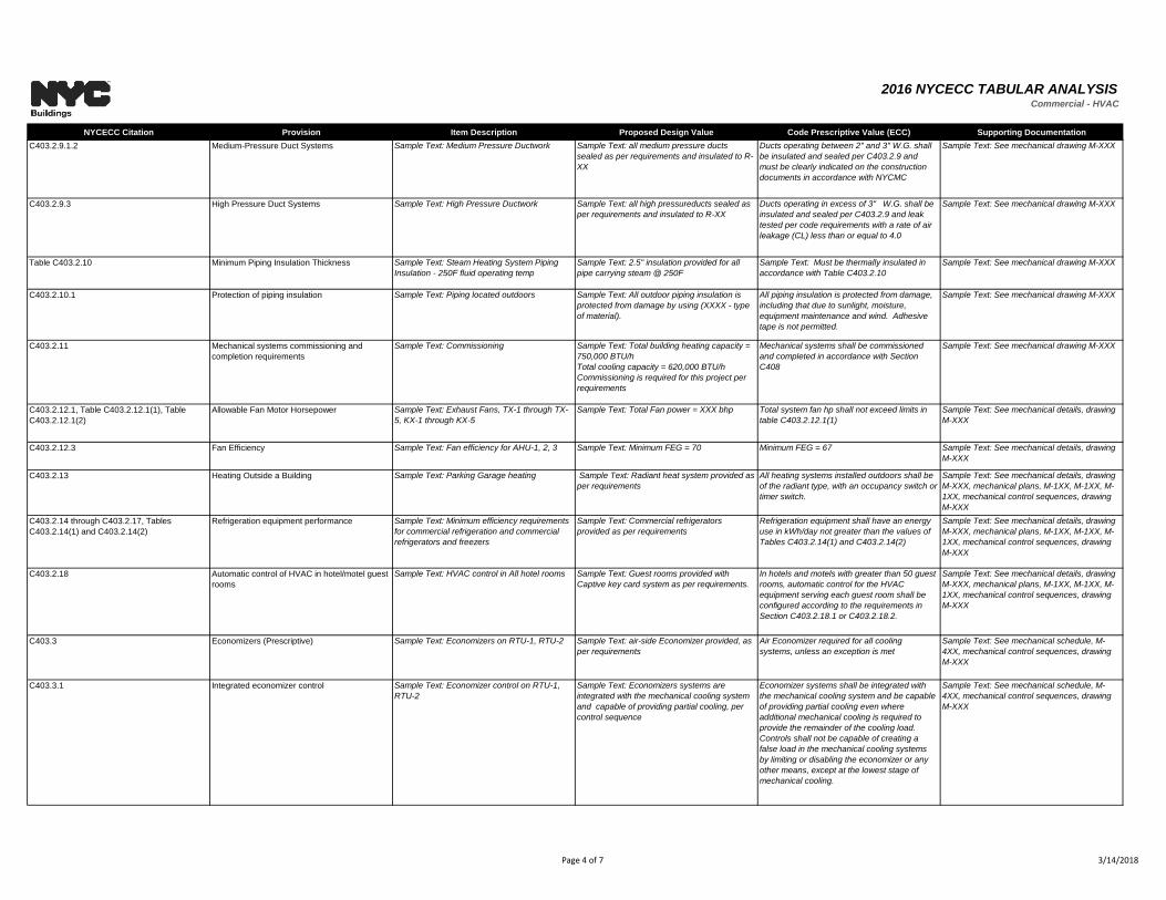
2016 NYCECC TABULAR ANALYSISCommercial - HVAC
NYCECC Citation Provision Item Description Proposed Design Value Code Prescriptive Value (ECC) Supporting Documentation
C403.2.9.1.2 Medium-Pressure Duct Systems Sample Text: Medium Pressure Ductwork Sample Text: all medium pressure ducts
sealed as per requirements and insulated to R-
XX
Ducts operating between 2" and 3" W.G. shall
be insulated and sealed per C403.2.9 and
must be clearly indicated on the construction
documents in accordance with NYCMC
Sample Text: See mechanical drawing M-XXX
C403.2.9.3 High Pressure Duct Systems Sample Text: High Pressure Ductwork Sample Text: all high pressureducts sealed as
per requirements and insulated to R-XX
Ducts operating in excess of 3" W.G. shall be
insulated and sealed per C403.2.9 and leak
tested per code requirements with a rate of air
leakage (CL) less than or equal to 4.0
Sample Text: See mechanical drawing M-XXX
Table C403.2.10 Minimum Piping Insulation Thickness Sample Text: Steam Heating System Piping
Insulation - 250F fluid operating temp
Sample Text: 2.5" insulation provided for all
pipe carrying steam @ 250F
Sample Text: Must be thermally insulated in
accordance with Table C403.2.10
Sample Text: See mechanical drawing M-XXX
C403.2.10.1 Protection of piping insulation Sample Text: Piping located outdoors Sample Text: All outdoor piping insulation is
protected from damage by using (XXXX - type
of material).
All piping insulation is protected from damage,
including that due to sunlight, moisture,
equipment maintenance and wind. Adhesive
tape is not permitted.
Sample Text: See mechanical drawing M-XXX
C403.2.11 Mechanical systems commissioning and
completion requirements
Sample Text: Commissioning Sample Text: Total building heating capacity =
750,000 BTU/h
Total cooling capacity = 620,000 BTU/h
Commissioning is required for this project per
requirements
Mechanical systems shall be commissioned
and completed in accordance with Section
C408
Sample Text: See mechanical drawing M-XXX
C403.2.12.1, Table C403.2.12.1(1), Table
C403.2.12.1(2)
Allowable Fan Motor Horsepower Sample Text: Exhaust Fans, TX-1 through TX-
5, KX-1 through KX-5
Sample Text: Total Fan power = XXX bhp Total system fan hp shall not exceed limits in
table C403.2.12.1(1)
Sample Text: See mechanical details, drawing
M-XXX
C403.2.12.3 Fan Efficiency Sample Text: Fan efficiency for AHU-1, 2, 3 Sample Text: Minimum FEG = 70 Minimum FEG = 67 Sample Text: See mechanical details, drawing
M-XXX
C403.2.13 Heating Outside a Building Sample Text: Parking Garage heating Sample Text: Radiant heat system provided as
per requirements
All heating systems installed outdoors shall be
of the radiant type, with an occupancy switch or
timer switch.
Sample Text: See mechanical details, drawing
M-XXX, mechanical plans, M-1XX, M-1XX, M-
1XX, mechanical control sequences, drawing
M-XXX
C403.2.14 through C403.2.17, Tables
C403.2.14(1) and C403.2.14(2)
Refrigeration equipment performance Sample Text: Minimum efficiency requirements
for commercial refrigeration and commercial
refrigerators and freezers
Sample Text: Commercial refrigerators
provided as per requirements
Refrigeration equipment shall have an energy
use in kWh/day not greater than the values of
Tables C403.2.14(1) and C403.2.14(2)
Sample Text: See mechanical details, drawing
M-XXX, mechanical plans, M-1XX, M-1XX, M-
1XX, mechanical control sequences, drawing
M-XXX
C403.2.18 Automatic control of HVAC in hotel/motel guest
rooms
Sample Text: HVAC control in All hotel rooms Sample Text: Guest rooms provided with
Captive key card system as per requirements.
In hotels and motels with greater than 50 guest
rooms, automatic control for the HVAC
equipment serving each guest room shall be
configured according to the requirements in
Section C403.2.18.1 or C403.2.18.2.
Sample Text: See mechanical details, drawing
M-XXX, mechanical plans, M-1XX, M-1XX, M-
1XX, mechanical control sequences, drawing
M-XXX
C403.3 Economizers (Prescriptive) Sample Text: Economizers on RTU-1, RTU-2 Sample Text: air-side Economizer provided, as
per requirements
Air Economizer required for all cooling
systems, unless an exception is met
Sample Text: See mechanical schedule, M-
4XX, mechanical control sequences, drawing
M-XXX
C403.3.1 Integrated economizer control Sample Text: Economizer control on RTU-1,
RTU-2
Sample Text: Economizers systems are
integrated with the mechanical cooling system
and capable of providing partial cooling, per
control sequence
Economizer systems shall be integrated with
the mechanical cooling system and be capable
of providing partial cooling even where
additional mechanical cooling is required to
provide the remainder of the cooling load.
Controls shall not be capable of creating a
false load in the mechanical cooling systems
by limiting or disabling the economizer or any
other means, except at the lowest stage of
mechanical cooling.
Sample Text: See mechanical schedule, M-
4XX, mechanical control sequences, drawing
M-XXX
Page 4 of 7 3/14/2018
2016 NYCECC TABULAR ANALYSISCommercial - HVAC
NYCECC Citation Provision Item Description Proposed Design Value Code Prescriptive Value (ECC) Supporting Documentation
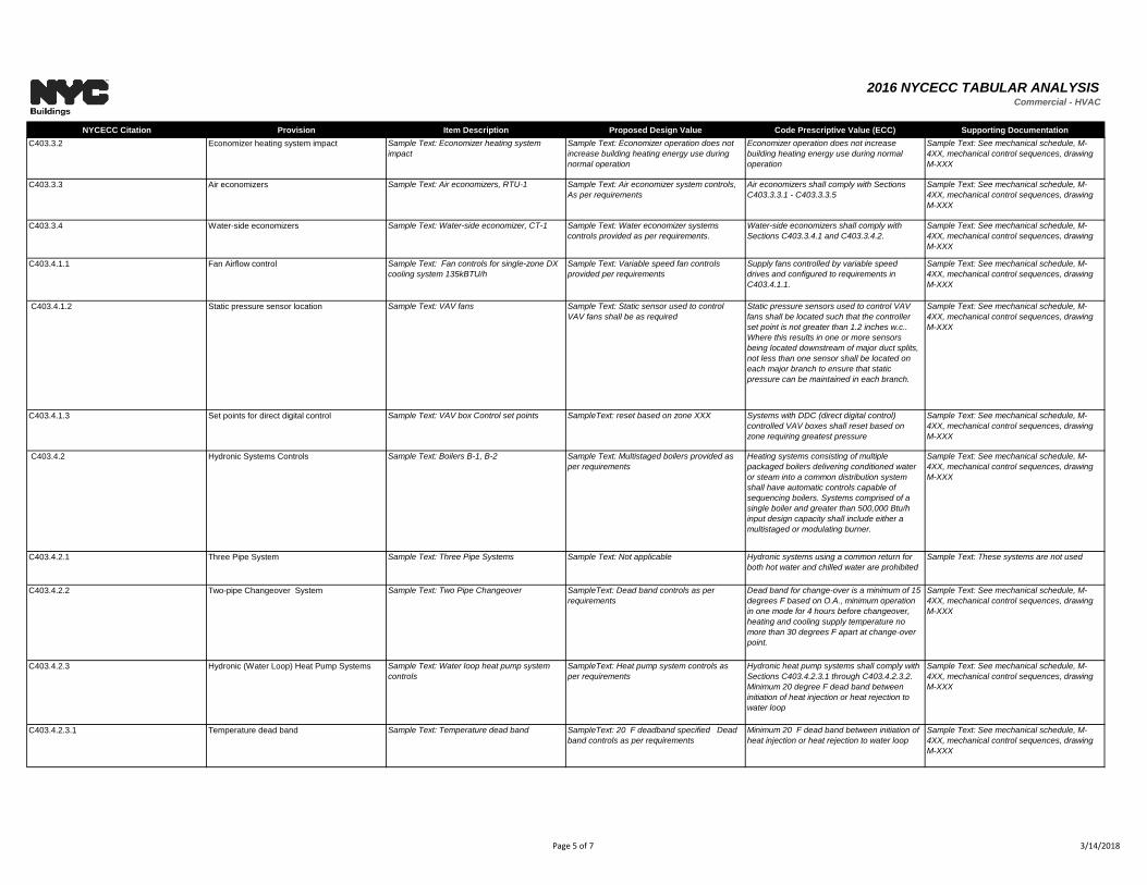
C403.3.2 Economizer heating system impact Sample Text: Economizer heating system
impact
Sample Text: Economizer operation does not
increase building heating energy use during
normal operation
Economizer operation does not increase
building heating energy use during normal
operation
Sample Text: See mechanical schedule, M-
4XX, mechanical control sequences, drawing
M-XXX
C403.3.3 Air economizers Sample Text: Air economizers, RTU-1 Sample Text: Air economizer system controls,
As per requirements
Air economizers shall comply with Sections
C403.3.3.1 - C403.3.3.5
Sample Text: See mechanical schedule, M-
4XX, mechanical control sequences, drawing
M-XXX
C403.3.4 Water-side economizers Sample Text: Water-side economizer, CT-1 Sample Text: Water economizer systems
controls provided as per requirements.
Water-side economizers shall comply with
Sections C403.3.4.1 and C403.3.4.2.
Sample Text: See mechanical schedule, M-
4XX, mechanical control sequences, drawing
M-XXX
C403.4.1.1 Fan Airflow control Sample Text: Fan controls for single-zone DX
cooling system 135kBTU/h
Sample Text: Variable speed fan controls
provided per requirements
Supply fans controlled by variable speed
drives and configured to requirements in
C403.4.1.1.
Sample Text: See mechanical schedule, M-
4XX, mechanical control sequences, drawing
M-XXX
C403.4.1.2 Static pressure sensor location Sample Text: VAV fans Sample Text: Static sensor used to control
VAV fans shall be as required
Static pressure sensors used to control VAV
fans shall be located such that the controller
set point is not greater than 1.2 inches w.c..
Where this results in one or more sensors
being located downstream of major duct splits,
not less than one sensor shall be located on
each major branch to ensure that static
pressure can be maintained in each branch.
Sample Text: See mechanical schedule, M-
4XX, mechanical control sequences, drawing
M-XXX
C403.4.1.3 Set points for direct digital control Sample Text: VAV box Control set points SampleText: reset based on zone XXX Systems with DDC (direct digital control)
controlled VAV boxes shall reset based on
zone requiring greatest pressure
Sample Text: See mechanical schedule, M-
4XX, mechanical control sequences, drawing
M-XXX
C403.4.2 Hydronic Systems Controls Sample Text: Boilers B-1, B-2 Sample Text: Multistaged boilers provided as
per requirements
Heating systems consisting of multiple
packaged boilers delivering conditioned water
or steam into a common distribution system
shall have automatic controls capable of
sequencing boilers. Systems comprised of a
single boiler and greater than 500,000 Btu/h
input design capacity shall include either a
multistaged or modulating burner.
Sample Text: See mechanical schedule, M-
4XX, mechanical control sequences, drawing
M-XXX
C403.4.2.1 Three Pipe System Sample Text: Three Pipe Systems Sample Text: Not applicable Hydronic systems using a common return for
both hot water and chilled water are prohibited
Sample Text: These systems are not used
C403.4.2.2 Two-pipe Changeover System Sample Text: Two Pipe Changeover SampleText: Dead band controls as per
requirements
Dead band for change-over is a minimum of 15
degrees F based on O.A., minimum operation
in one mode for 4 hours before changeover,
heating and cooling supply temperature no
more than 30 degrees F apart at change-over
point.
Sample Text: See mechanical schedule, M-
4XX, mechanical control sequences, drawing
M-XXX
C403.4.2.3 Hydronic (Water Loop) Heat Pump Systems Sample Text: Water loop heat pump system
controls
SampleText: Heat pump system controls as
per requirements
Hydronic heat pump systems shall comply with
Sections C403.4.2.3.1 through C403.4.2.3.2.
Minimum 20 degree F dead band between
initiation of heat injection or heat rejection to
water loop
Sample Text: See mechanical schedule, M-
4XX, mechanical control sequences, drawing
M-XXX
C403.4.2.3.1 Temperature dead band Sample Text: Temperature dead band SampleText: 20 F deadband specified Dead
band controls as per requirements
Minimum 20 F dead band between initiation of
heat injection or heat rejection to water loop
Sample Text: See mechanical schedule, M-
4XX, mechanical control sequences, drawing
M-XXX
Page 5 of 7 3/14/2018
2016 NYCECC TABULAR ANALYSISCommercial - HVAC
NYCECC Citation Provision Item Description Proposed Design Value Code Prescriptive Value (ECC) Supporting Documentation
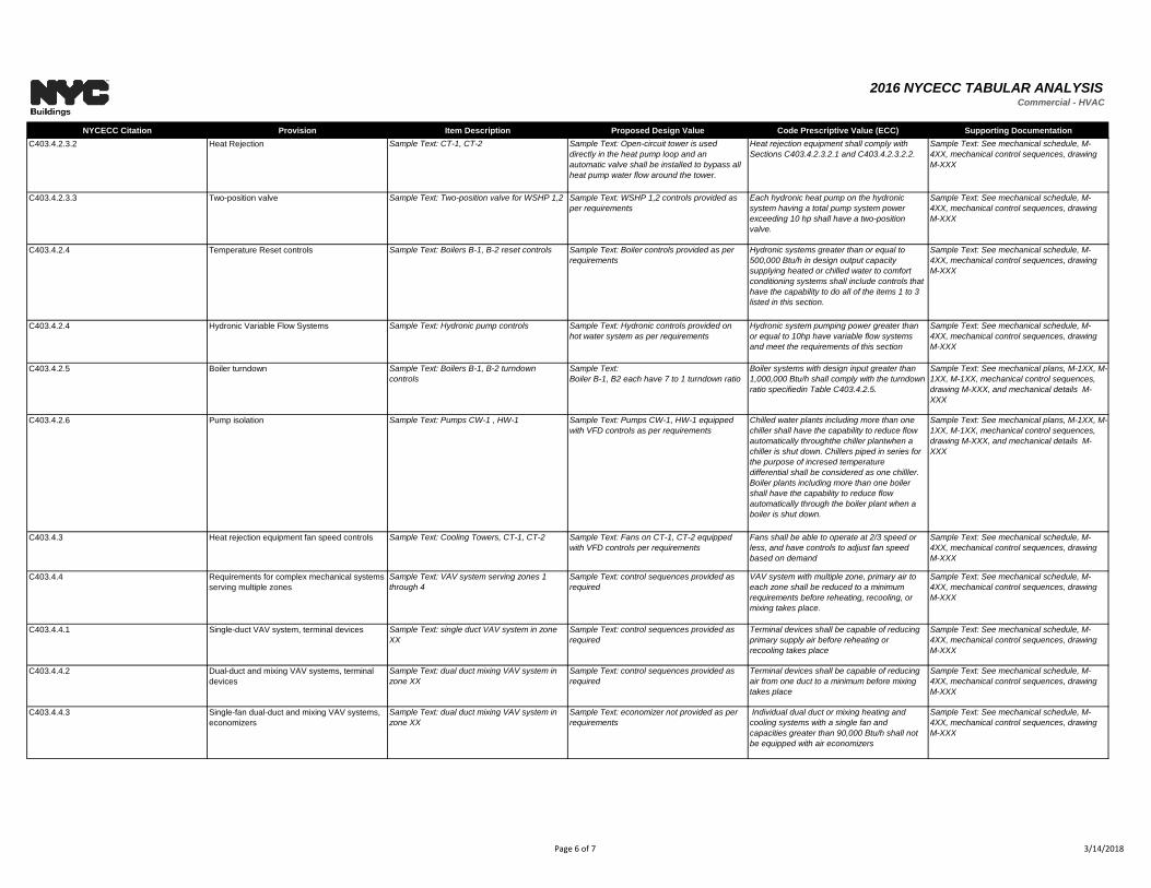
C403.4.2.3.2 Heat Rejection Sample Text: CT-1, CT-2 Sample Text: Open-circuit tower is used
directly in the heat pump loop and an
automatic valve shall be installed to bypass all
heat pump water flow around the tower.
Heat rejection equipment shall comply with
Sections C403.4.2.3.2.1 and C403.4.2.3.2.2.
Sample Text: See mechanical schedule, M-
4XX, mechanical control sequences, drawing
M-XXX
C403.4.2.3.3 Two-position valve Sample Text: Two-position valve for WSHP 1,2 Sample Text: WSHP 1,2 controls provided as
per requirements
Each hydronic heat pump on the hydronic
system having a total pump system power
exceeding 10 hp shall have a two-position
valve.
Sample Text: See mechanical schedule, M-
4XX, mechanical control sequences, drawing
M-XXX
C403.4.2.4 Temperature Reset controls Sample Text: Boilers B-1, B-2 reset controls Sample Text: Boiler controls provided as per
requirements
Hydronic systems greater than or equal to
500,000 Btu/h in design output capacity
supplying heated or chilled water to comfort
conditioning systems shall include controls that
have the capability to do all of the items 1 to 3
listed in this section.
Sample Text: See mechanical schedule, M-
4XX, mechanical control sequences, drawing
M-XXX
C403.4.2.4 Hydronic Variable Flow Systems Sample Text: Hydronic pump controls Sample Text: Hydronic controls provided on
hot water system as per requirements
Hydronic system pumping power greater than
or equal to 10hp have variable flow systems
and meet the requirements of this section
Sample Text: See mechanical schedule, M-
4XX, mechanical control sequences, drawing
M-XXX
C403.4.2.5 Boiler turndown Sample Text: Boilers B-1, B-2 turndown
controls
Sample Text:
Boiler B-1, B2 each have 7 to 1 turndown ratio
Boiler systems with design input greater than
1,000,000 Btu/h shall comply with the turndown
ratio specifiedin Table C403.4.2.5.
Sample Text: See mechanical plans, M-1XX, M-
1XX, M-1XX, mechanical control sequences,
drawing M-XXX, and mechanical details M-
XXX
C403.4.2.6 Pump isolation Sample Text: Pumps CW-1 , HW-1 Sample Text: Pumps CW-1, HW-1 equipped
with VFD controls as per requirements
Chilled water plants including more than one
chiller shall have the capability to reduce flow
automatically throughthe chiller plantwhen a
chiller is shut down. Chillers piped in series for
the purpose of incresed temperature
differential shall be considered as one chilller.
Boiler plants including more than one boiler
shall have the capability to reduce flow
automatically through the boiler plant when a
boiler is shut down.
Sample Text: See mechanical plans, M-1XX, M-
1XX, M-1XX, mechanical control sequences,
drawing M-XXX, and mechanical details M-
XXX
C403.4.3 Heat rejection equipment fan speed controls Sample Text: Cooling Towers, CT-1, CT-2 Sample Text: Fans on CT-1, CT-2 equipped
with VFD controls per requirements
Fans shall be able to operate at 2/3 speed or
less, and have controls to adjust fan speed
based on demand
Sample Text: See mechanical schedule, M-
4XX, mechanical control sequences, drawing
M-XXX
C403.4.4 Requirements for complex mechanical systems
serving multiple zones
Sample Text: VAV system serving zones 1
through 4
Sample Text: control sequences provided as
required
VAV system with multiple zone, primary air to
each zone shall be reduced to a minimum
requirements before reheating, recooling, or
mixing takes place.
Sample Text: See mechanical schedule, M-
4XX, mechanical control sequences, drawing
M-XXX
C403.4.4.1 Single-duct VAV system, terminal devices Sample Text: single duct VAV system in zone
XX
Sample Text: control sequences provided as
required
Terminal devices shall be capable of reducing
primary supply air before reheating or
recooling takes place
Sample Text: See mechanical schedule, M-
4XX, mechanical control sequences, drawing
M-XXX
C403.4.4.2 Dual-duct and mixing VAV systems, terminal
devices
Sample Text: dual duct mixing VAV system in
zone XX
Sample Text: control sequences provided as
required
Terminal devices shall be capable of reducing
air from one duct to a minimum before mixing
takes place
Sample Text: See mechanical schedule, M-
4XX, mechanical control sequences, drawing
M-XXX
C403.4.4.3 Single-fan dual-duct and mixing VAV systems,
economizers
Sample Text: dual duct mixing VAV system in
zone XX
Sample Text: economizer not provided as per
requirements
Individual dual duct or mixing heating and
cooling systems with a single fan and
capacities greater than 90,000 Btu/h shall not
be equipped with air economizers
Sample Text: See mechanical schedule, M-
4XX, mechanical control sequences, drawing
M-XXX
Page 6 of 7 3/14/2018
2016 NYCECC TABULAR ANALYSISCommercial - HVAC
NYCECC Citation Provision Item Description Proposed Design Value Code Prescriptive Value (ECC) Supporting Documentation
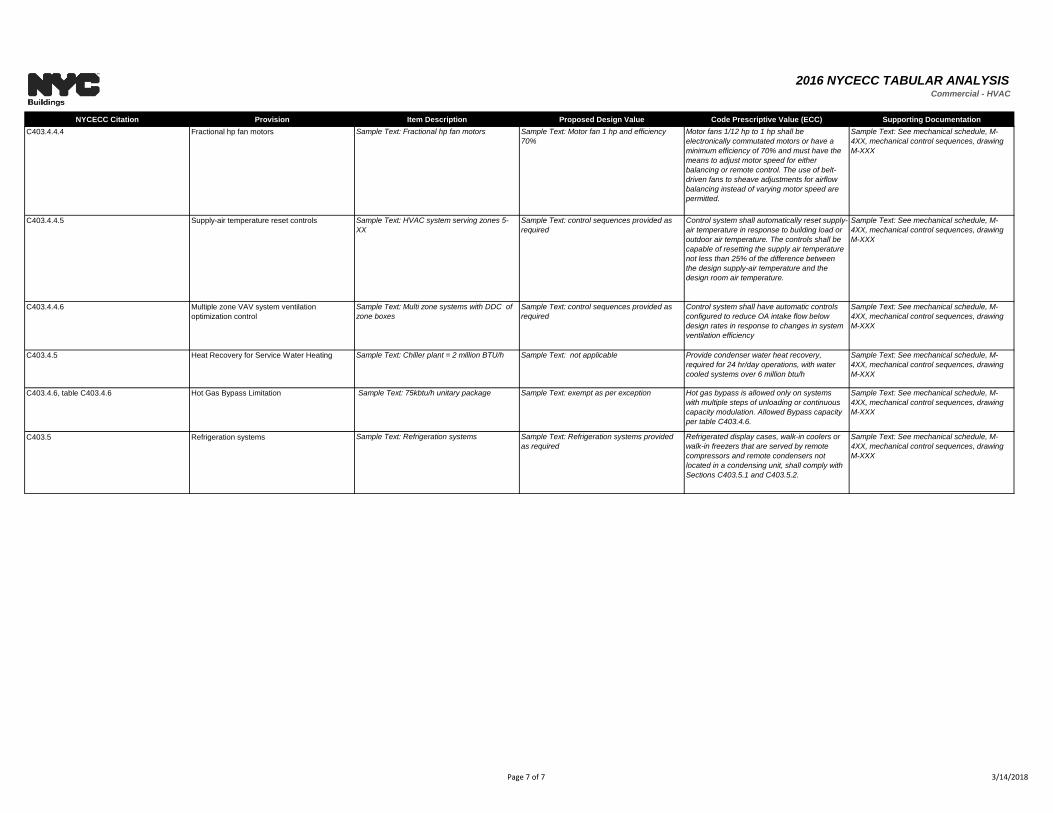
C403.4.4.4 Fractional hp fan motors Sample Text: Fractional hp fan motors Sample Text: Motor fan 1 hp and efficiency
70%
Motor fans 1/12 hp to 1 hp shall be
electronically commutated motors or have a
minimum efficiency of 70% and must have the
means to adjust motor speed for either
balancing or remote control. The use of belt-
driven fans to sheave adjustments for airflow
balancing instead of varying motor speed are
permitted.
Sample Text: See mechanical schedule, M-
4XX, mechanical control sequences, drawing
M-XXX
C403.4.4.5 Supply-air temperature reset controls Sample Text: HVAC system serving zones 5-
XX
Sample Text: control sequences provided as
required
Control system shall automatically reset supply-
air temperature in response to building load or
outdoor air temperature. The controls shall be
capable of resetting the supply air temperature
not less than 25% of the difference between
the design supply-air temperature and the
design room air temperature.
Sample Text: See mechanical schedule, M-
4XX, mechanical control sequences, drawing
M-XXX
C403.4.4.6 Multiple zone VAV system ventilation
optimization control
Sample Text: Multi zone systems with DDC of
zone boxes
Sample Text: control sequences provided as
required
Control system shall have automatic controls
configured to reduce OA intake flow below
design rates in response to changes in system
ventilation efficiency
Sample Text: See mechanical schedule, M-
4XX, mechanical control sequences, drawing
M-XXX
C403.4.5 Heat Recovery for Service Water Heating Sample Text: Chiller plant = 2 million BTU/h Sample Text: not applicable Provide condenser water heat recovery,
required for 24 hr/day operations, with water
cooled systems over 6 million btu/h
Sample Text: See mechanical schedule, M-
4XX, mechanical control sequences, drawing
M-XXX
C403.4.6, table C403.4.6 Hot Gas Bypass Limitation Sample Text: 75kbtu/h unitary package Sample Text: exempt as per exception Hot gas bypass is allowed only on systems
with multiple steps of unloading or continuous
capacity modulation. Allowed Bypass capacity
per table C403.4.6.
Sample Text: See mechanical schedule, M-
4XX, mechanical control sequences, drawing
M-XXX
C403.5 Refrigeration systems Sample Text: Refrigeration systems Sample Text: Refrigeration systems provided
as required
Refrigerated display cases, walk-in coolers or
walk-in freezers that are served by remote
compressors and remote condensers not
located in a condensing unit, shall comply with
Sections C403.5.1 and C403.5.2.
Sample Text: See mechanical schedule, M-
4XX, mechanical control sequences, drawing
M-XXX
Page 7 of 7 3/14/2018
2016 NYCECC TABULAR ANALYSISCommercial - DHW
NYCECC Citation Provision Item Description Proposed Design Value Code Prescriptive Value (ECC) Supporting Documentation
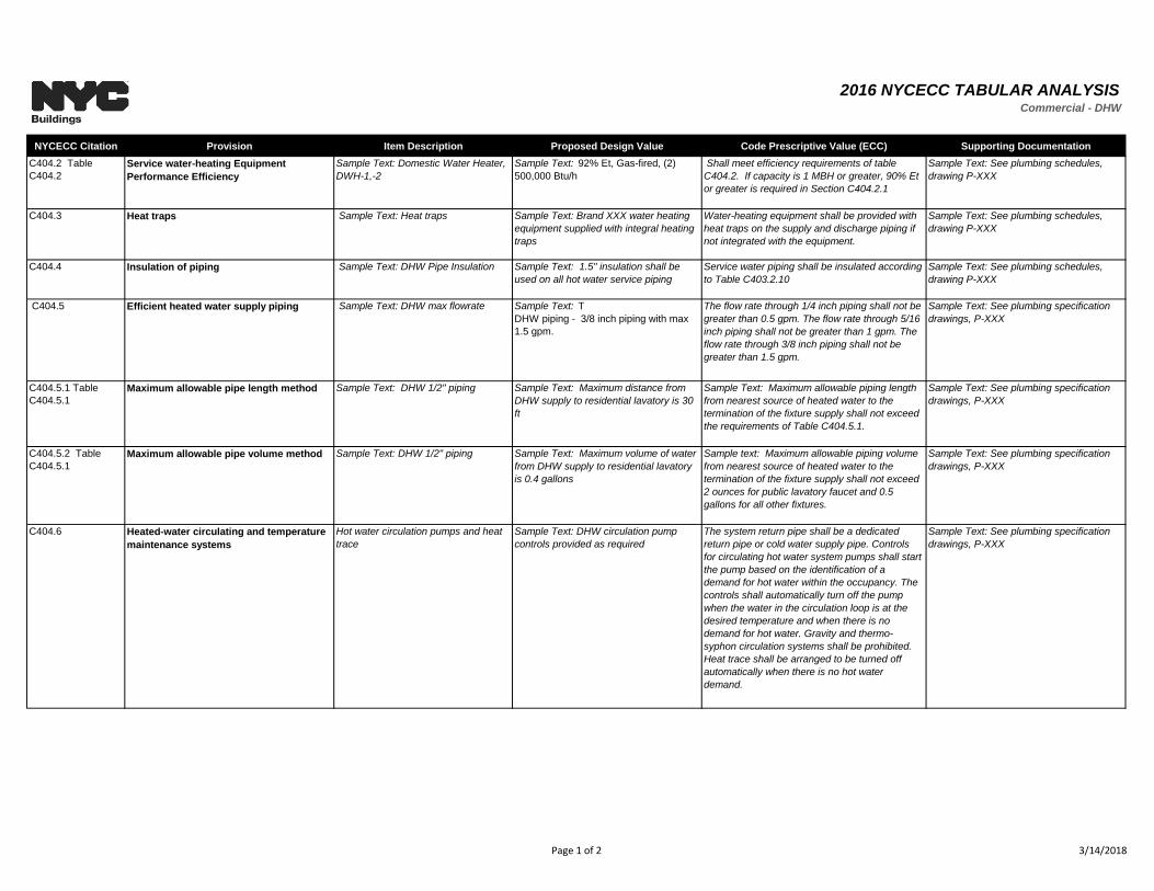
C404.2 Table
C404.2
Service water-heating Equipment
Performance Efficiency
Sample Text: Domestic Water Heater,
DWH-1,-2
Sample Text: 92% Et, Gas-fired, (2)
500,000 Btu/h
Shall meet efficiency requirements of table
C404.2. If capacity is 1 MBH or greater, 90% Et
or greater is required in Section C404.2.1
Sample Text: See plumbing schedules,
drawing P-XXX
C404.3 Heat traps Sample Text: Heat traps Sample Text: Brand XXX water heating
equipment supplied with integral heating
traps
Water-heating equipment shall be provided with
heat traps on the supply and discharge piping if
not integrated with the equipment.
Sample Text: See plumbing schedules,
drawing P-XXX
C404.4 Insulation of piping Sample Text: DHW Pipe Insulation Sample Text: 1.5" insulation shall be
used on all hot water service piping
Service water piping shall be insulated according
to Table C403.2.10
Sample Text: See plumbing schedules,
drawing P-XXX
C404.5 Efficient heated water supply piping Sample Text: DHW max flowrate Sample Text: T
DHW piping - 3/8 inch piping with max
1.5 gpm.
The flow rate through 1/4 inch piping shall not be
greater than 0.5 gpm. The flow rate through 5/16
inch piping shall not be greater than 1 gpm. The
flow rate through 3/8 inch piping shall not be
greater than 1.5 gpm.
Sample Text: See plumbing specification
drawings, P-XXX
C404.5.1 Table
C404.5.1
Maximum allowable pipe length method Sample Text: DHW 1/2" piping Sample Text: Maximum distance from
DHW supply to residential lavatory is 30
ft
Sample Text: Maximum allowable piping length
from nearest source of heated water to the
termination of the fixture supply shall not exceed
the requirements of Table C404.5.1.
Sample Text: See plumbing specification
drawings, P-XXX
C404.5.2 Table
C404.5.1
Maximum allowable pipe volume method Sample Text: DHW 1/2" piping Sample Text: Maximum volume of water
from DHW supply to residential lavatory
is 0.4 gallons
Sample text: Maximum allowable piping volume
from nearest source of heated water to the
termination of the fixture supply shall not exceed
2 ounces for public lavatory faucet and 0.5
gallons for all other fixtures.
Sample Text: See plumbing specification
drawings, P-XXX
C404.6 Heated-water circulating and temperature
maintenance systems
Hot water circulation pumps and heat
trace
Sample Text: DHW circulation pump
controls provided as required
The system return pipe shall be a dedicated
return pipe or cold water supply pipe. Controls
for circulating hot water system pumps shall start
the pump based on the identification of a
demand for hot water within the occupancy. The
controls shall automatically turn off the pump
when the water in the circulation loop is at the
desired temperature and when there is no
demand for hot water. Gravity and thermo-
syphon circulation systems shall be prohibited.
Heat trace shall be arranged to be turned off
automatically when there is no hot water
demand.
Sample Text: See plumbing specification
drawings, P-XXX
Page 1 of 2 3/14/2018
2016 NYCECC TABULAR ANALYSISCommercial - DHW
NYCECC Citation Provision Item Description Proposed Design Value Code Prescriptive Value (ECC) Supporting Documentation
C404.7 Demand recirculation controls Demand recirculation controls Sample Text: Demand recirculation
controls provided per requirements
The control shall start the pump upon receiving a
signal from the action of a user of a fixture or
appliance, sensing the presence of a user of a
fixture or sensing the flow of hot or tempered
water to a fixture fitting or appliance. The control
shall limit the temperature of the water entering
the cold-watrer piping to 104 degrees F (40
degrees C).
Sample Text: See plumbing specification
drawings, P-XXX
C404.8 Drain water heat recovery units Drain water heat recovery units Sample Text: Drain water heat recovery
provided on all shower drains
Potable waterside pressure loss shall be less
than 10 psi at maximum deisgn flow. For Group
R occupancies, the efficiency of drain water heat
recovery unit efficiency shall be in accordance
with CSA B55.1.
Sample Text: See plumbing specification
drawings, P-XXX
C404.9 Energy consumption of pools and
permanent spas (Mandatory)
Sample Text: Pool and Permanent
Spa Controls
Sample Text: Pool heaters and pump
motors provided with controls as per
requirements.
Shall be controlled by the requirements in
Sections C404.9.1 through C404.9.3.
Sample Text: See plumbing specification
drawings, P-XXX
C404.9.3 Covers Sample Text: Pool Covers for outdoor
heated pool
Sample Text: Outdoor heated pools
equipped with a vapor-retardant cover
Outdoor heated pools and outdoor permanent
spas shall be provided with a vapor-retardant
cover or other approved vapor-retardant means.
Sample Text: See plumbing specification
drawings, P-XXX
C404.10 Energy consumption of portable spas
(Mandatory)
Sample Text: Energy consumption of
portable spas
Sample Text: The energy consumption of
electric-powered portable spas shall be
controlled by the requirements of APSP
14.
The energy consumption of electric-powered
portable spas shall be controlled by the
requirements of APSP 14.
Sample Text: See plumbing specification
drawings, P-XXX
C404.11 Service water-heating system
commissioning and completion
requirements
Sample Text: Service water-heating
system commissioning and completion
requirements
Sample Text:
Total heating capacity (including Service
Water) = 750,000 BTU/h
Commissioning will be performed per
requirements.
Service water-heating systems, swimming pool
water-heating systems, spa water-heating
systems and the controls for those systems shall
be commissioned and completed in accordance
with Section C408.2.
Sample Text: See plumbing specification
drawings, P-XXX
Page 2 of 2 3/14/2018
2016 NYCECC TABULAR ANALYSISCommercial - Lighting
NYCECC Citation Provision Item Description Proposed Design Value Code Prescriptive Value (ECC) Supporting Documentation
C405.1 Dwelling Unit Lighting Sample Text: Dwelling unit
lighting fixtures
Sample Text: All lighting fixtures
contain high efficacy lamps.
75 percent of the lamps in permanently installed lighting fixtures,
or not less than 75 percent of the permanently installed lighting
fixture, other than low voltage lighting, shall be high-efficacy
lamps.
Sample Text: see drawing E-XXX (Lighting
fixture schedules)
C405.2 Lighting controls (Mandatory) Sample Text: interior lighting
controls include occupancy
sensors, daylight responsive
controls, bi-level controls, and
automatic shut-off
Sample Text: Occupancy
sensors in restrooms,
conference rooms, open offices;
daylight responsive controls in
all offices; bi-level controls in
stairwells; automatic shut-off via
BMS for all lighting
Lighting systems shall be provided with controls as specified in
Sections C405.2.1, C405.2.2, C405.2.3, C405.2.4 and C405.2.5.
Exceptions: Lighting controls are not required for the following: 1.
Areas designated as security or emergency areas that are
required to be continuously lighted. 2. Interior exit stairways,
interior exit ramps and exit passageways. 3. Emergency egress
lighting that is normally off.
Sample Text: see drawing EN-XXX (Lighting
fixture schedule & narratives)
C405.2.1 Occupant sensor controls Sample Text: Occupant
sensor controls are provided
in each conference room,
restroom, storage area,
stairwell and open plan office
Sample Text: Occupancy &
vacancy sensors provided with
20 minute shut off limit
Occupant sensor controls in spaces other than warehouses
specified in Section C405.2.1 shall comply with the following: 1.
Automatically turn off lights within 20 minutes of all occupants
leaving the space. 2. Be manual on or controlled to automatically
turn the lighting on to not more than 50 percent power.
Exceptions: 1. Full automatic-on controls shall be permitted to
control lighting in open plan offices, public corridors, stairways,
restrooms, primary building entrance areas and lobbies, and
areas where manual-on operation would endanger the safety or
security of the room or building occupants. 2. Manual-on controls
shall be required for classrooms (not including shop classrooms,
laboratory classrooms, and preschool classrooms),
conference/meeting rooms, employee lunch and break rooms,
and offices smaller than 200 square feet (18.5 m ²) in area. Such
sensors and controls shall not have an override switch that
converts from manual-on to automatic-on functionality, and may
have a grace period of up to 30 seconds to turn on the lighting
automatically after the sensor has turned off the lighting if
occupancy is detected. 3. Shall incorporate a manual control to
allow occupants to turn lights off.
Sample Text: see drawing E-XXX (lighting
fixture schedule & narratives)
C405.2.2, Time-switch controls Sample Text: Time-switch
controls at room XX-X
Sample Text: Time-switch
controls have been provided.
Each area of the building that is not provided with occupant
sensor controls complying with Section C405.2.1.1 shall be
provided with time switch controls complying with Section
C405.2.2.1. Exception: Where a manual control provides light
reduction in accordance with Section C405.2.2.2, automatic
controls shall not be required for the following: 1. Sleeping units.
2. Spaces where patient care is directly provided. 3. Spaces
where an automatic shutoff would endanger occupant safety or
security. 4. Lighting intended for continuous operation. 5. Shop
and laboratory classrooms.
Sample Text: see drawing E-XXX (Lighting
fixture schedules & narratives)
Page 1 of 4 3/14/2018
2016 NYCECC TABULAR ANALYSISCommercial - Lighting
NYCECC Citation Provision Item Description Proposed Design Value Code Prescriptive Value (ECC) Supporting Documentation
C405.2.2.1 Time-switch control function Sample Text: Time-switch
controls
Sample Text: Time-switch
controls provided as required.
Each space provided with time-switch controls shall also be
provided with a manual control for light reduction in accordance
with section C405.2.2.2. Time-switch controls shall include an
override switching device that complies with the following: 1.
Have a minimum 7-day clock. 2. Be capable of being set for
seven different day types per week. 3. Incorporate an automatic
holiday "shutoff" feature, which turns off all controlled lighting
loads for at least 24 hours and then resumes normally scheduled
operations. 4. Have program backup capabilities, which prevent
the loss of program and time settings for at least 10 hours, if
power is interrupted. 5. Include an override switch that complies
with the following: 5.1. The override switch shall be a manual
control. 5.2. The override switch, when initiated, shall permit the
controlled lighting to remain on for not more than 2 hours. 5.3.
Any individual override switch shall control the lighting for an area
not larger than 5,000 square feet (465m ²). Exceptions as per this
code section.
Sample Text: see drawing E-XXX (Lighting
fixture schedules & narratives)
C405.2.2.2 Light-reduction controls Sample Text: Light-reduction
controls
Sample Text: Light-reduction
controls provided in open space
on 5th floor.
Spaces required to have light-reduction controls shall have a
manual control that allows the occupant to reduce the connected
lighting load in a reasonably uniform illumination pattern by at
least 50 percent.
Sample Text: see drawing E-XXX (Lighting
fixture schedules & narratives)
C405.2.2.3 Manual controls Sample Text: Manual controls
at rooms XX-X through XX-X
Sample Text: Manual controls
provided as required
Manual controls for lights shall comply with the following:
1. Shall be readily accessible to occupants.
2. Shall be located where the controlled lights are visible, or shall
identify the area served by the lights and indicate their status.
Sample Text: see drawing E-XXX (Lighting
fixture schedules) and A-XXX (reflected
ceiling plan).
C405.2.3 Daylight-responsive controls Sample Text: Daylight-
responsive controls.
Sample Text: N/A Daylight
responsive controls are not
required for the following:
Dwelling units and sleeping
units. (Exception #2)
Daylight responsive controls complying with Section C405.2.3.1
shall be provided to control the electric lights within daylight zones
in the following spaces:
1. Spaces with a total of more than 150 watts of general
lighting within sidelight daylight zones complying with Section
C405.2.3.2. General lighting does not include lighting that is
required to have specific application control in accordance with
Section C405.2.4.
2. Spaces with a total of more than 150 watts of general lighting
within toplight daylight zones complying with Section C405.2.3.3.
See drawing EN-XXX
C405.2.3.1 Daylight-responsive control
function
Sample Text: Daylight-
responsive controls
Sample Text: Daylight-
responsive controls shall be
provided as per C405.2.3.1.
Where required, daylight-responsive controls shall be provided
within each space for control of lights in that space and shall
comply with requirements of C405.2.3.1.
See drawing EN-XXX
C405.2.3.2 Sidelight daylight zone Sample Text: Sidelight
daylight zones, Floors 2-10
Sample Text: Sidelight daylight
zones provided as per
C405.2.3.2.
The sidelight daylight zone is the floor area adjacent to vertical
fenestration which complies with C405.2.3.2
See drawing EN-XXX
Page 2 of 4 3/14/2018
2016 NYCECC TABULAR ANALYSISCommercial - Lighting
NYCECC Citation Provision Item Description Proposed Design Value Code Prescriptive Value (ECC) Supporting Documentation
C405.2.3.3 Toplight daylight zone Sample Text: Toplight daylight
zone, Floor 10
Sample Text: Toplight daylight
zone on 5th floor complies with
C405.2.3.3.
The toplight daylight zone is the floor area underneath a roof
fenestration assembly which complies withC405.2.3.3.
See drawing EN-XXX
C405.2.4 Specific application controls. Sample Text: Retail display
case lighting
Sample Text: Display and accent
light D4 to D9 shall be controlled
by a dedicated control that is
independent of the controls for
other lighting within the room or
space.
Specific application controls shall be provided for the following:
1. Display and accent light shall be controlled by a dedicated
control that is independent of the controls for other lighting within
the room or space.
2. Lighting in cases used for display case purposes shall be
controlled by a dedicated control that is independent of the
controls for other lighting within the room or space.
3. Hotel and motel sleeping units and guest suites shall have a
master control device that is capable of automatically switching
off all installed luminaires and switched receptacles within 20
minutes after all occupants leave the room.
Sample Text: see drawing EN-XXX
C405.2.5 Exterior lighting controls Sample Text: Exterior lighting
controls
Sample Text: Lighting on the
north building facade shall have
controls that automatically shut
off the lighting as a function of
dawn/dusk and a set opening
and closing time. See lighting
Plan.
Lighting for exterior applications other than emergency lighting
that is intended to be automatically off during building operation,
lighting specifically required to meet health and life safety
requirements or decorative gas lighting systems shall comply with
the requirements of C405.2.5.
See drawing EN-XXX
C405.3 Exit Signs Sample Text: Two new LED
exit signs to be provided
Sample Text: 5W per side Internally illuminated exit signs shall not exceed 5 watts per side. Sample Text: see drawing E-XXX (Lighting
fixture schedules)
C405.4 Interior lighting power
requirements
Sample Text: Interior lighting
power requirements
Sample Text:
Open Office: 0.88 W/SF
Conf Rm: 0.92 W/SF
Stairwell: 0.43 W/SF
Restroom: 0.60 W/SF
LPD value for building is less
than the interior lighting power
calculated under Section
C405.4.2. See drawing EN-XXX.
Sample text:
Open Office: 0.90 W/SF
Conf Rm: 1.23 W/SF
Stairwell: 0.69 W/SF
Restroom: 0.98 W/SF
The total connected interior lighting power shall be determined in
accordance with Equation 4-9.
Sample Text: see drawing EN-XXX (Lighting
fixture schedules)
C405.5 Exterior lighting (Mandatory). Sample Text: Total connected
load of proposed exterior
lighting for lighting zone 3
Sample Text: 7.66 kW
The total exterior lighting power
is less than the exterior lighting
power calculated under Section
C405.5. See drawing EN-XXX.
Sample text: 10.21 kW
The exterior lighting power allowance shall be determined in
accordance with Section C405.5.1.
Sample Text: A-XXX drawings (Reflected
Ceiling Plans for all floors) E-XXX drawings
(Reflected Ceiling Plans for all floors) E-XXX -
XXX (Fixture schedule, control narrative, and
details)
Page 3 of 4 3/14/2018
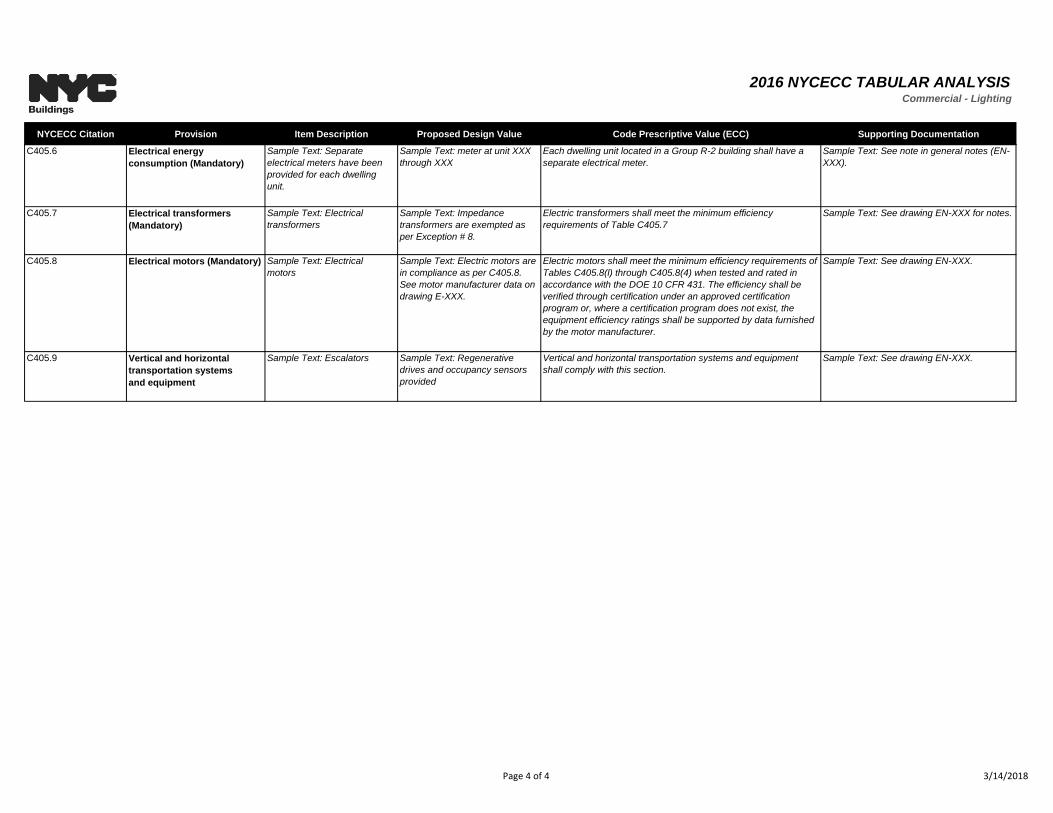
2016 NYCECC TABULAR ANALYSISCommercial - Lighting
NYCECC Citation Provision Item Description Proposed Design Value Code Prescriptive Value (ECC) Supporting Documentation
C405.6 Electrical energy
consumption (Mandatory)
Sample Text: Separate
electrical meters have been
provided for each dwelling
unit.
Sample Text: meter at unit XXX
through XXX
Each dwelling unit located in a Group R-2 building shall have a
separate electrical meter.
Sample Text: See note in general notes (EN-
XXX).
C405.7 Electrical transformers
(Mandatory)
Sample Text: Electrical
transformers
Sample Text: Impedance
transformers are exempted as
per Exception # 8.
Electric transformers shall meet the minimum efficiency
requirements of Table C405.7
Sample Text: See drawing EN-XXX for notes.
C405.8 Electrical motors (Mandatory) Sample Text: Electrical
motors
Sample Text: Electric motors are
in compliance as per C405.8.
See motor manufacturer data on
drawing E-XXX.
Electric motors shall meet the minimum efficiency requirements of
Tables C405.8(l) through C405.8(4) when tested and rated in
accordance with the DOE 10 CFR 431. The efficiency shall be
verified through certification under an approved certification
program or, where a certification program does not exist, the
equipment efficiency ratings shall be supported by data furnished
by the motor manufacturer.
Sample Text: See drawing EN-XXX.
C405.9 Vertical and horizontal
transportation systems
and equipment
Sample Text: Escalators Sample Text: Regenerative
drives and occupancy sensors
provided
Vertical and horizontal transportation systems and equipment
shall comply with this section.
Sample Text: See drawing EN-XXX.
Page 4 of 4 3/14/2018
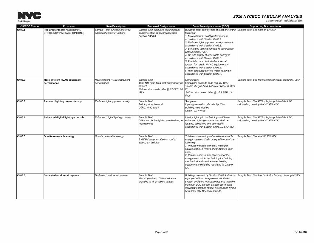
2016 NYCECC TABULAR ANALYSISCommercial - Additional Eff.
NYCECC Citation Provision Item Description Proposed Design Value Code Prescriptive Value (ECC) Supporting Documentation
C406.1 Requirements (for ADDITIONAL
EFFICIENCY PACKAGE OPTIONS)
Sample Text: Choose one of six
additional efficiency options
Sample Text: Reduced lighting power
density system in accordance with
Section C406.3.
Buildings shall comply with at least one of the
following:
1. More efficient HVAC performance in
accordance with Section C406.2.
2. Reduced lighting power density system in
accordance with Section C406.3.
3. Enhanced lighting controls in accordance
with Section C406.4.
4. On-site supply of renewable energy in
accordance with Section C406.5.
5. Provision of a dedicated outdoor air
system for certain HV AC equipment in
accordance with Section C406.6.
6. High-efficiency service water heating in
accordance with Section C406.7.
C406.2 More efficient HVAC equipment
performance
More efficient HVAC equipment
performance
Sample Text:
1000 MBH gas-fired, hot water boiler @
96% Et,
300 ton air-cooled chiller @ 12 EER, 16
IPLV
Sample text:
Equipment exceeds code min. by 10%:
1 MBTU/hr gas-fired, hot water boiler @ 88%
Et,
300 ton air-cooled chiller @ 10.1 EER, 14
IPLV
C406.3 Reduced lighting power density Reduced lighting power density Sample Text:
Building Area Method
Office: 0.50 W/SF
Sample text:
Lighting exceeds code min. by 10%:
Building Area Method
Office: 0.74 W/SF
C406.4 Enhanced digital lighting controls Enhanced digital lighting controls Sample Text:
Office and lobby lighting provided as per
requirements
Interior lighting in the building shall have
enhanced lighting controls that shall be
located, scheduled and operated in
accordance with Section C405.2.2 & C406.4
C406.5 On-site renewable energy On-site renewable energy Sample Text:
5 kW PV array installed on roof of
10,000 SF building
Total minimum ratings of on-site renewable
energy systems shall comply with one of the
following:
1. Provide not less than 0.50 watts per
square foot (5.4 W/m ²) of conditioned floor
area.
2. Provide not less than 3 percent of the
energy used within the building for building
mechanical and service water heating
equipment and lighting regulated in Chapter
C4.
C406.6 Dedicated outdoor air system Dedicated outdoor air system Sample Text:
MAU-1 provides 100% outside air
provided to all occupied spaces.
Buildings covered by Section C403.4 shall be
equipped with an independent ventilation
system designed to provide not less than the
minimum 1OO percent outdoor air to each
individual occupied space, as specified by the
New York City Mechanical Code.
Sample Text: See A-XXX, EN-XXX
Sample Text: See Mechanical schedule, drawing M-XXX
Sample Text: See note on EN-XXX
Sample Text: See Mechanical schedule, drawing M-XXX
Sample Text: See RCPs, Lighting Schedule, LPD
calculation, drawing A-XXX, EN-XXX
Sample Text: See RCPs, Lighting Schedule, LPD
calculation, drawing A-XXX, EN-XXX
Page 1 of 2 3/14/2018
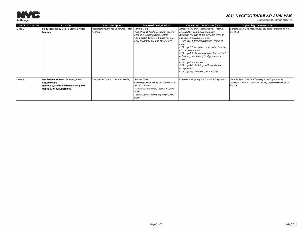
2016 NYCECC TABULAR ANALYSISCommercial - Additional Eff.
NYCECC Citation Provision Item Description Proposed Design Value Code Prescriptive Value (ECC) Supporting Documentation
C406.7 Reduced energy use in service water
heating
Reduced energy use in service water
heating
Sample Text:
75% of DHW load provided by waste-
heat from Cogeneration system
*As a motel, Group R-1 building, this
project complies to use this method.
At least 60% of the domestic hot water is
provided by waste-heat recovery.
Buildings shall be of the following types to
use this compliance method:
1. Group R-I: Boarding houses, hotels or
motels.
2. Group 1-2: Hospitals, psychiatric hospitals
and nursing homes.
3. Group A-2: Restaurants and banquet halls
or buildings containing food preparation
areas.
4. Group F: Laundries.
5. Group R-2: Buildings with residential
occupancies.
6. Group A-3: Health clubs and spas.
C408.2 Mechanical renewable energy, and
service water
heating systems commissioning and
completion requirements
Mechanical System Commissioning Sample Text:
Commissioning will be performed on all
HVAC systems
Total building heating capacity: 1,585
MBH
Total building cooling capacity: 1,400
MBH
Commissioning required on HVAC systems
Sample Text: See Mechanical schedule, drawing M-XXX,
EN-XXX
Sample Text: See total heating & cooling capacity
calculation M-XXX, commissioning requirement note on
EN-XXX
Page 2 of 2 3/14/2018