Embed Size (px)
Citation preview
FEASIBILITY STUDY REPORT 2017.09.07 Jones Architecture 1
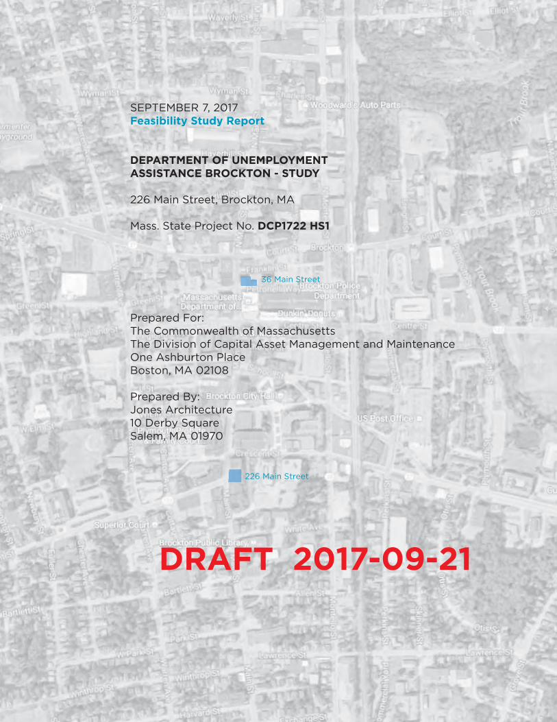
SEPTEMBER 7, 2017Feasibility Study Report
DEPARTMENT OF UNEMPLOYMENT ASSISTANCE BROCKTON - STUDY
226 Main Street, Brockton, MA
Mass. State Project No. DCP1722 HS1
36 Main Street
Prepared For:The Commonwealth of MassachusettsThe Division of Capital Asset Management and MaintenanceOne Ashburton PlaceBoston, MA 02108
Prepared By:Jones Architecture10 Derby SquareSalem, MA 01970
226 Main Street
DRAFT 2017-09-21

2 Department of Unemployment Assistance, Brockton MA. DCAMM DCP1722 HS1
TABLE OF CONTENTS
VOLUME 1 - FEASIBILITY ANALYSIS
ACKNOWLEDGMENTS A. PREFACE
B. EXECUTIVE SUMMARY
C. BUILDING PROGRAM 1. Introduction 2. Tabular Program 3. Program Descriptions 4. Right Sized Program Diagrams 5. Additional Program Notes D. FEASIBILITY ANALYSIS
1. Preferred Alternative Summary 2. Site Plan 3. Plans 4. Section 5. Interior Precedent Imagery 6. Elevation Studies E. PRELIMINARY SUSTAINABILITY STRATEGIES (LEED E0484)
F. REGULATORY ANALYSIS
G. OUTSTANDING ISSUES FOR CERTIFIABLE BUILDING STUDY
H. SYSTEMS NARRATIVES 1. Introduction 2. Code Analysis 3. Structural 4. Plumbing 5. Fire Protection 6. Mechanical 7. Electrical, AV, Communications I. COST ESTIMATE
J. PROJECT SCHEDULE - STUDY, DESIGN, CONSTRUCTION
FEASIBILITY STUDY REPORT 2017.09.07 Jones Architecture 3
TABLE OF CONTENTS
VOLUME 2 - APPENDIX
Contains information on the background of the study and the decision to move for-ward with the property at 226 Main Street. For additional information refer to Task 3 Report.
A. EXISTING CONDITIONS 1. City of Brockton Context Plan 2. 226 Main Street Floor Plans 3. 226 Main Street Existing Conditions Report
B. INVESTIGATION OF ALTERNATIVES 1. Investigation of Alternatives a. Introduction b. Planning Guidelines and Assumptions c. Building Systems Synopsis d. Planning Options Summary 2. 36 Main Street Preliminary Program Fit 3. 226 Main Street Preliminary Program Fit 4. 226 Main Street Expanded Planning Exercise

4 Department of Unemployment Assistance, Brockton MA. DCAMM DCP1722 HS1
ACKNOWLEDGMENTS
The following individuals and firms contributed to this report:
Owner:
Division of Capital Asset Management and MaintenanceCarol Gladstone, CommissionerElizabeth Minnis, Deputy Commissioner, Office of Planning, Design, and ConstructionRobin Luna Whitman, Deputy Director, Programming
Gail Rosenberg. Senior Project ManagerOne Ashburton Place, 15th Floor, Boston, MA [email protected] x31572
User Agency:
Department of Unemployment Assistance
Richard Jeffers, [email protected]
Wendy Savary, Director of Claims and [email protected]
Marie-Lise Sobande, Deputy Chief of Staff, Department of Workforce [email protected]
Design Team:
ARCHITECTURE
Jones Architecture10 Derby Sq., Ste. N3Salem, MA 01970978.744.5200
Richard Jones, [email protected]
Marc Perras, Project [email protected]
Sarah Tarbet, Project [email protected]
FEASIBILITY STUDY REPORT 2017.09.07 Jones Architecture 5
STRUCTURAL ENGINEER
RSE Associates, Inc.63 Pleasant Street, Ste. 300Watertown, MA 02472617.926.9300
Jennifer McClain, [email protected]
MECHANICAL, PLUMBING, and FIRE PROTECTION
BVH Integrated ServicesOne Gateway Center, Ste. 701Newton, MA 02458617.658.9008
Tom Iskra, [email protected]
ELECTRICAL, FIRE ALARM, COMMUNICATIONS
ART Engineering Corp.38 Front Street, Fl. 3Worcester, MA 01608508.797.0333
Robbie Burnett, Project [email protected]
BUILDING CODE
Code Red Consultants154 Turnpike Rd., Ste. 200Southborough, MA 01772617.500.7633
Caitlin Gamache, Project [email protected]
COST ESTIMATING
VJ Associates of New England, Inc.35 Highland Circle, Ste. 200Needham, MA 02494781.444.8200
Clive Tysoe, [email protected]
6 Department of Unemployment Assistance, Brockton MA. DCAMM DCP1722 HS1
A. PREFACE
This study was prepared for the Office of Planning Design and Construction of the Division of Capital Asset Management and Maintenance, Commonwealth of Massachusetts, in accordance with Mas-sachusetts General Laws Chapter 7C, Section 59. It is intended to investigate agency capital needs, evaluate alternatives, and recommend a solution that corresponds to the current needs for the Department of Unemployment Assistance in Brockton.
The study provides a clear and detailed frame of reference for the design and implementation pro-cess and recommends a solution that can be accomplished within the appropriation or authorization for that project. It includes a space program which reflects the user agency’s needs a description of the project requirements, an accurate estimate of capital costs, and an implementation schedule.
Conceptual building designs, where included, are not intended to constrain the final design, but rather to illustrate functional relationships, demonstrate the practical operation of design criteria and conformance with applicable codes and standards, and serve as the basis for developing an accurate cost estimate.
Before DCAMM can enter into a contract for final design services, this study must be certified by the Commissioner of DCAMM. Thereafter no substantial changes can be made to the extents of improve-ments during the implementation process. In subsequent phases, the gross square footage may not change by more than 10% of the number specified in the study or the study will need to be recerti-fied.

FEASIBILITY STUDY REPORT 2017.09.07 Jones Architecture 7
8 Department of Unemployment Assistance, Brockton MA. DCAMM DCP1722 HS1
B. EXECUTIVE SUMMARY

FEASIBILITY STUDY REPORT 2017.09.07 Jones Architecture 9
10 Department of Unemployment Assistance, Brockton MA. DCAMM DCP1722 HS1
B. EXECUTIVE SUMMARY
PROJECT SUMMARY
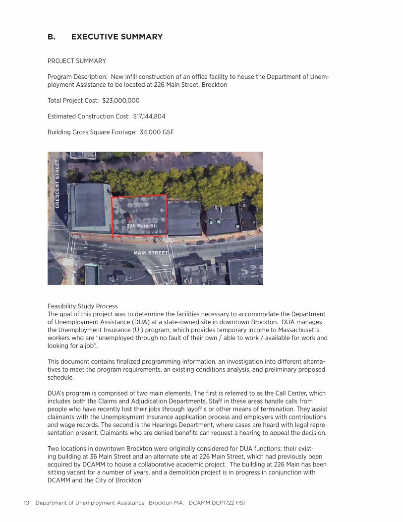
Program Description: New infill construction of an office facility to house the Department of Unem-ployment Assistance to be located at 226 Main Street, Brockton
Total Project Cost: $23,000,000
Estimated Construction Cost: $17,144,804
Building Gross Square Footage: 34,000 GSF
Feasibility Study ProcessThe goal of this project was to determine the facilities necessary to accommodate the Department of Unemployment Assistance (DUA) at a state-owned site in downtown Brockton. DUA manages the Unemployment Insurance (UI) program, which provides temporary income to Massachusetts workers who are “unemployed through no fault of their own / able to work / available for work and looking for a job”.
This document contains finalized programming information, an investigation into different alterna-tives to meet the program requirements, an existing conditions analysis, and preliminary proposed schedule.
DUA’s program is comprised of two main elements. The first is referred to as the Call Center, which includes both the Claims and Adjudication Departments. Staff in these areas handle calls from people who have recently lost their jobs through layoff s or other means of termination. They assist claimants with the Unemployment Insurance application process and employers with contributions and wage records. The second is the Hearings Department, where cases are heard with legal repre-sentation present. Claimants who are denied benefits can request a hearing to appeal the decision.
Two locations in downtown Brockton were originally considered for DUA functions: their exist-ing building at 36 Main Street and an alternate site at 226 Main Street, which had previously been acquired by DCAMM to house a collaborative academic project. The building at 226 Main has been sitting vacant for a number of years, and a demolition project is in progress in conjunction with DCAMM and the City of Brockton.
FEASIBILITY STUDY REPORT 2017.09.07 Jones Architecture 11
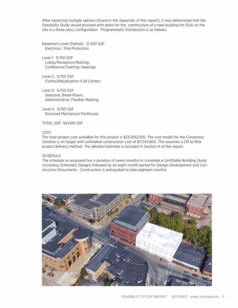
After exploring multiple options (found in the Appendix of this report), it was determined that the Feasibility Study would proceed with plans for the construction of a new building for DUA on the site in a three-story configuration. Programmatic Distribution is as follows:
Basement Level (Partial): 12,300 GSF Electrical / Fire Protection
Level 1: 9,750 GSF Lobby/Reception/Waiting; Conference/Training; Hearings
Level 2: 9,750 GSF Claims/Adjudication (Call Center)
Level 3: 9,750 GSF Seasonal; Break Room; Administrative; Flexible Meeting
Level 4: 9,750 GSF Enclosed Mechanical Penthouse
TOTAL GSF: 34,000 GSF
COST The total project cost available for this project is $23,000,000. The cost model for the Consensus Solution is on target with estimated construction cost of $17,144,804. This assumes a CM at Risk project delivery method. The detailed estimate is included in Section H of this report.
SCHEDULEThe schedule as proposed has a duration of seven months to complete a Certifiable Building Study (including Schematic Design) followed by an eight month period for Design Development and Con-struction Documents. Construction is anticipated to take eighteen months.
12 Department of Unemployment Assistance, Brockton MA. DCAMM DCP1722 HS1
C. BUILDING PROGRAM

FEASIBILITY STUDY REPORT 2017.09.07 Jones Architecture 13
14 Department of Unemployment Assistance, Brockton MA. DCAMM DCP1722 HS1
C. BUILDING PROGRAM
INTRODUCTION
The Department of Unemployment Assistance in Brockton is composed of two primary components, the Call Center and Hearings. The Call Center is further broken down into two departments, Claims and Adjudica-tion. In addition there are Administrative Offices, Shared Spaces, and Critical infrastructural components to consider.
The DUA employs both permanent and seasonal employees, the latter of which work at times when unem-ployment spikes, typically around the winter holidays in the in the summer. In addition, spare desks must be maintained for times when there are larger shifts in unemployment that may last for a year or more. These are referred to as Flexible desks.
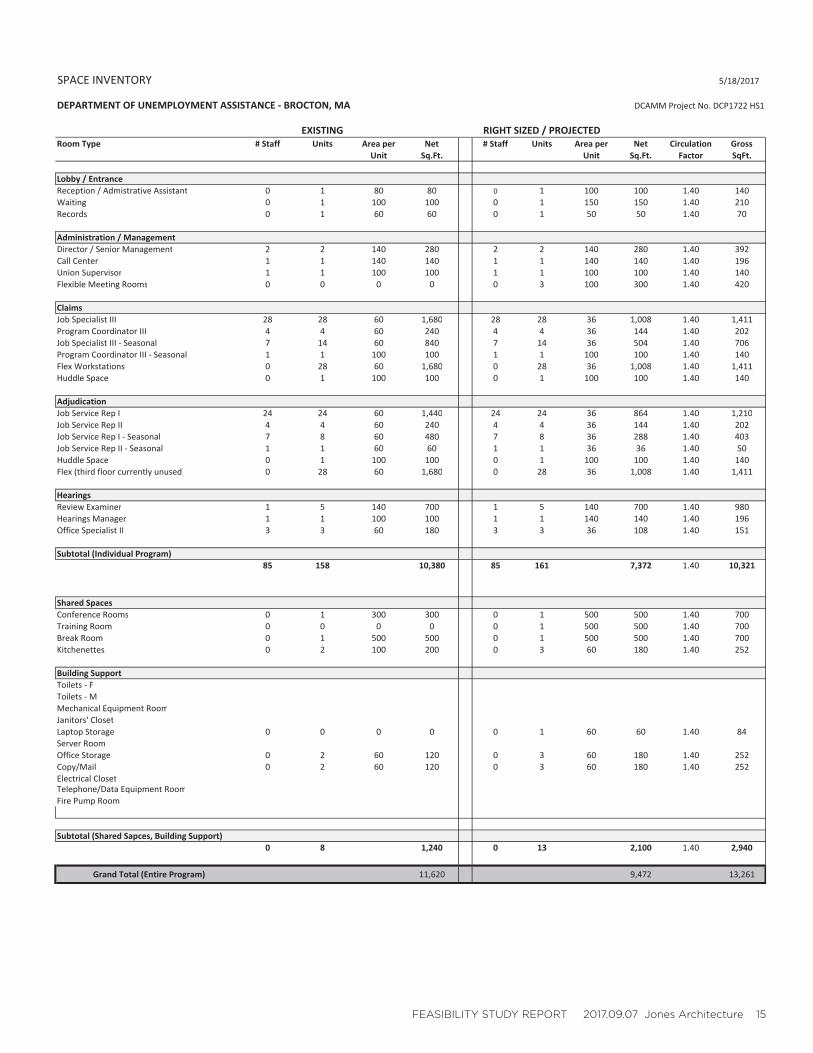
The PROGRAM TABULATION at right shows both the existing spaces housed at 36 Main Street and the Right Sized/Projected needs moving forward. The following pages provide further descriptions of program ele-ments and block diagrams indicating relative sizing and spatial relationships.
FEASIBILITY STUDY REPORT 2017.09.07 Jones Architecture 15
SPACE INVENTORY 5/18/2017
DEPARTMENT OF UNEMPLOYMENT ASSISTANCE BROCTON, MA
EXISTING RIGHT SIZED / PROJECTEDRoom Type # Staff Units Area per Net # Staff Units Area per Net Circulation Gross
Unit Sq.Ft. Unit Sq.Ft. Factor SqFt.
Lobby / EntranceReception / Admistrative Assistant 0 1 80 80 0 1 100 100 1.40 140Waiting 0 1 100 100 0 1 150 150 1.40 210Records 0 1 60 60 0 1 50 50 1.40 70
Administration / ManagementDirector / Senior Management 2 2 140 280 2 2 140 280 1.40 392Call Center 1 1 140 140 1 1 140 140 1.40 196Union Supervisor 1 1 100 100 1 1 100 100 1.40 140Flexible Meeting Rooms 0 0 0 0 0 3 100 300 1.40 420
ClaimsJob Specialist III 28 28 60 1,680 28 28 36 1,008 1.40 1,411Program Coordinator III 4 4 60 240 4 4 36 144 1.40 202Job Specialist III Seasonal 7 14 60 840 7 14 36 504 1.40 706Program Coordinator III Seasonal 1 1 100 100 1 1 100 100 1.40 140Flex Workstations 0 28 60 1,680 0 28 36 1,008 1.40 1,411Huddle Space 0 1 100 100 0 1 100 100 1.40 140
AdjudicationJob Service Rep I 24 24 60 1,440 24 24 36 864 1.40 1,210Job Service Rep II 4 4 60 240 4 4 36 144 1.40 202Job Service Rep I Seasonal 7 8 60 480 7 8 36 288 1.40 403Job Service Rep II Seasonal 1 1 60 60 1 1 36 36 1.40 50Huddle Space 0 1 100 100 0 1 100 100 1.40 140Flex (third floor currently unused) 0 28 60 1,680 0 28 36 1,008 1.40 1,411
HearingsReview Examiner 1 5 140 700 1 5 140 700 1.40 980Hearings Manager 1 1 100 100 1 1 140 140 1.40 196Office Specialist II 3 3 60 180 3 3 36 108 1.40 151
Subtotal (Individual Program)85 158 10,380 85 161 7,372 1.40 10,321
Shared SpacesConference Rooms 0 1 300 300 0 1 500 500 1.40 700Training Room 0 0 0 0 0 1 500 500 1.40 700Break Room 0 1 500 500 0 1 500 500 1.40 700Kitchenettes 0 2 100 200 0 3 60 180 1.40 252
Building SupportToilets FToilets MMechanical Equipment RoomJanitors' ClosetLaptop Storage 0 0 0 0 0 1 60 60 1.40 84Server RoomOffice Storage 0 2 60 120 0 3 60 180 1.40 252Copy/Mail 0 2 60 120 0 3 60 180 1.40 252Electrical ClosetTelephone/Data Equipment RoomFire Pump Room
Subtotal (Shared Sapces, Building Support)0 8 1,240 0 13 2,100 1.40 2,940
Grand Total (Entire Program) 11,620 9,472 13,261
DCAMM Project No. DCP1722 HS1

16 Department of Unemployment Assistance, Brockton MA. DCAMM DCP1722 HS1
C. BUILDING PROGRAM
PROGRAM DESCRIPTIONS
ADMINISTRATION 950SF
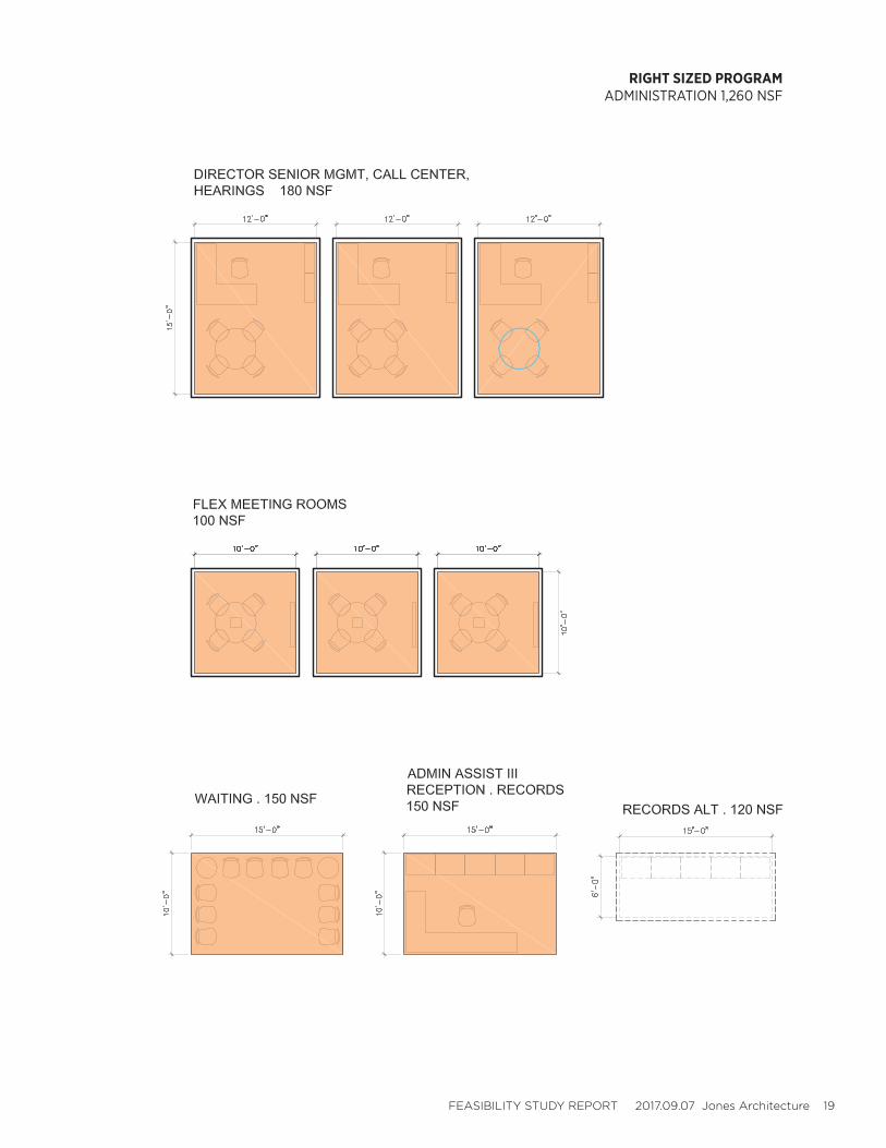
There are currently three (3) Director’s Offices, each of which needs to be retained for the future. Each should be approximately 140SF to accommodate small meetings.
A single closed office with guest chairs is needed for the Union Supervisor, approximately 100SF.
Additionally, three (3) Flexible Meeting Rooms which are unassigned serve as temporary visitor offices, small meeting rooms, or remote hearings spaces. Because of these functions, these meeting rooms are to contain high levels of technology.
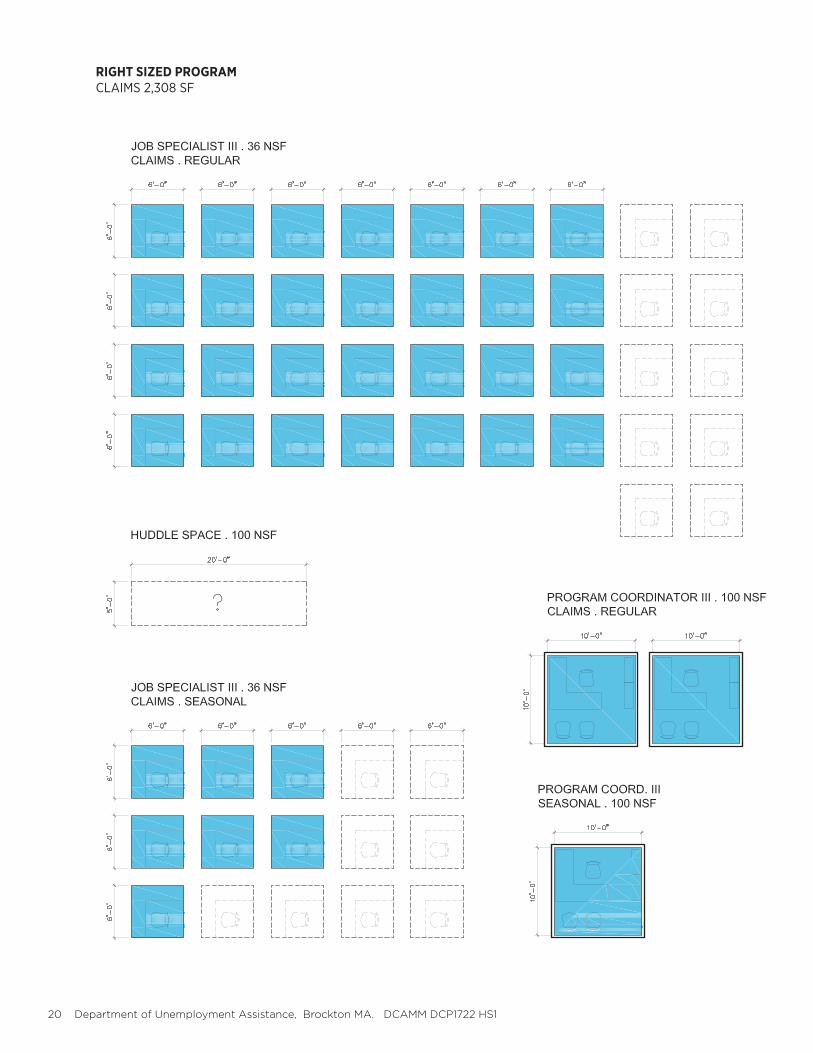
CLAIMS 2,300SF
The Claims Department currently consists of twenty-eight (28) cubicles that are in use and an addi-tional ten (10) that are unoccupied. All of these cubicles are to be retained for future use. Existing cubicle sizes vary but are approximately 6’X8’. This is more space than is needed, especially with the elimination of a printer at each desk. Future cubicles are to b 6’X6’ standard. Cubicle walls are to be 50” tall.
There are four Claims Managers distributed throughout the Claims Department. Managers require closed offices with a pair of guest chairs.
There is currently a “Huddle Space” in the Claims Department. This space is for frequent and short meetings of approximately 15 employees at a time and must remain unless a conference room can be located near by to serve this function.
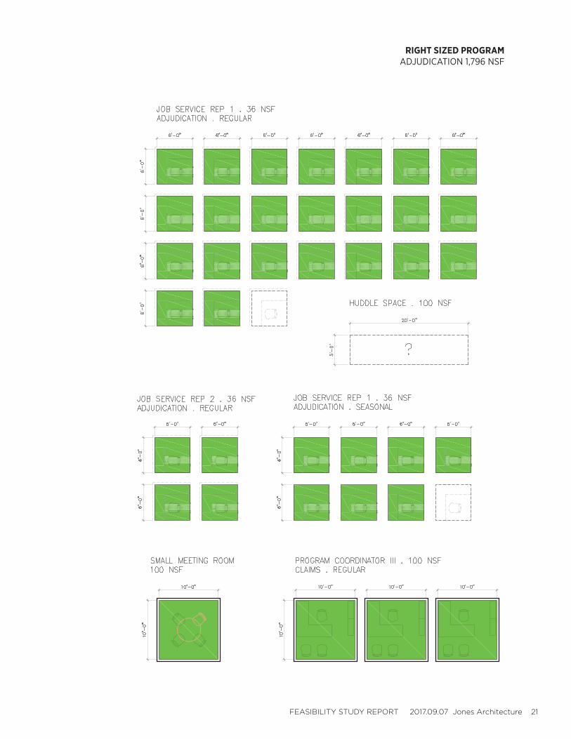
ADJUDICATION 1,500SF
The Adjudication Department currently consists of twenty-two (22) cubicles that are in use and one (1) that is unoccupied. All of these cubicles are to be retained for future use. All future cubicles are to be 6’X6’ standard, with cubicle walls at 50” tall. In addition, Adjudication cubicles are to have 12” glass extension panels mounted to the top of the cubicle walls for acoustic privacy.
There are four supervisors in the Adjudication Department. These are not closed offices but consist of 6’X6’ cubicles with added glass partitions. The proposed program calls for a single closed meet-ing room to accommodate up to (4) people to facilitate private conversations.
There is currently a “Huddle Space” in the Adjudication Department. This space is for frequent and short meetings of approximately 15 employees at a time. This function must remain but can occur in a conference room rather than a dedicated space.
SEASONAL Claims and Adjudication
The Seasonal area currently houses seventeen (17) occupied desks that are shared between Claims and Adjudication. That number should increase to twenty to twenty-five (20-25) in the future de-sign to allow for greater flexibility. Seasonal desks are used for almost ten months a year so cannot
FEASIBILITY STUDY REPORT 2017.09.07 Jones Architecture 17
be substituted for other programs at certain times - this must have dedicated space. Because these are not permanent workstations, however, there the possibility of using a desking system that is less cubicle-like, and inherently more flexible.
There is one Program Coordinator for the Seasonal staff who requires a closed office with guest chairs. This individual oversees both the Claims and Adjudication portions of the Seasonal staff.All seasonal staff should remain together in the same space if possible, and should be separate from the full time Call Center staff.
FLEXIBLE 1,000SF
The Call Center currently maintains twenty-eight (28) empty seats that can be filled on a more per-manent basis with shifts in the economy. Projections indicate that all of these seats should remain for future use, and that all should be 6’X6’ cubicles to which glass extension panels can be added at a later time if they will serve Adjudicators.
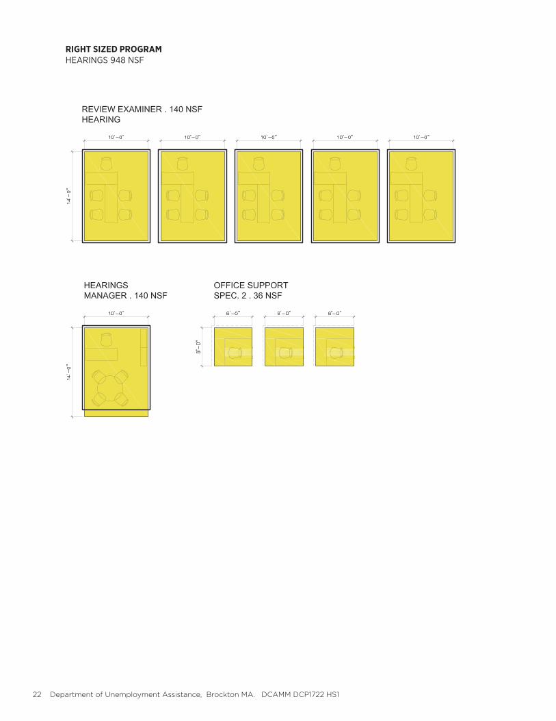
HEARINGS 1,150SF
The Hearings Department Consists of five (5) Hearings Offices, one (1) Hearings Manager, and three (3) Office Support workstations. Additional versions of this program and layout focusing on flexible workspace were discussed and dismissed; the current layout projects well for future use.
The layout of these offices is important to the way hearings are conducted. New furniture should replicate this layout.
ADMINISTRATION 300SF
The Administration space is the introduction of the public to the Department of Unemployment Assistance. It’s composed of a Reception Desk and a Waiting Area. The Reception Desk is staffed by one of the three Office Support staff from Hearings. While th Reception Desk currently houses Records Storage, it is preferable that this function be located to a closed, locked room.
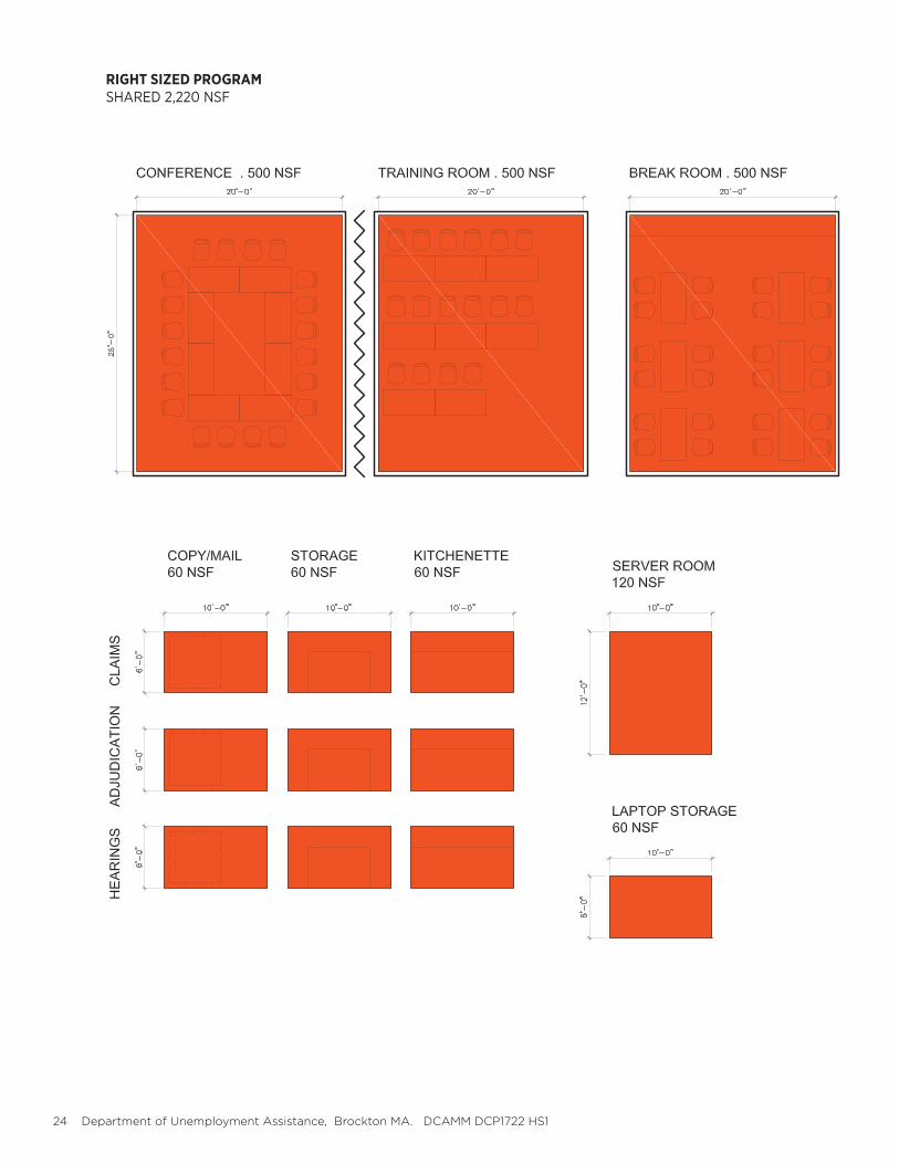
SHARED 2,250SF
Program projections have identified the need for three large Shared Spaces in the future, each being approximately 500SF. The Conference Room should seat at least sixteen (16) and needs to have ad-jacency to both Claims and Adjudication if it is to be used as huddle space for both of those groups.
Three Training Room should also seat sixteen (16) with flexible furniture that can be re-arranged if necessary. The training room will utilize laptops, making an adjacent Laptop Storage room nec-essary. If possible, having a movable partition between the Conference Room and Training Room would provide some added flexibility for occasional larger events.
The third large space is the Break Room. Seating for at least sixteen (16) is to be provided, as well as countertop, sink, refrigerator, microwave, two (2) vending machines, and two (2) trash containers. Details of the Break Room will need to be discussed further in design.
A centrally located Server Room that is as least as large as the current room will be necessary. Art Engineering also recommends Telecom closets at each floor to help with distribution and mainte-nance.
A centralized Copy/Mail area, office supply Storage Room, and Kitchenette are required for the Call Center and Hearings. Claims and Adjudication can share these amenities if they are sized according-ly. Hearings needs a separate space. Kitchenettes will include a piped coffee machine, microwave, under counter refrigerator, and sink (no disposal).

18 Department of Unemployment Assistance, Brockton MA. DCAMM DCP1722 HS1
C. BUILDING PROGRAM
RIGHT SIZED PROGRAMALL DEPARTMENTS 9,520 NSF
FEASIBILITY STUDY REPORT 2017.09.07 Jones Architecture 19
RIGHT SIZED PROGRAMADMINISTRATION 1,260 NSF
20 Department of Unemployment Assistance, Brockton MA. DCAMM DCP1722 HS1
RIGHT SIZED PROGRAMCLAIMS 2,308 SF
FEASIBILITY STUDY REPORT 2017.09.07 Jones Architecture 21
RIGHT SIZED PROGRAMADJUDICATION 1,796 NSF
22 Department of Unemployment Assistance, Brockton MA. DCAMM DCP1722 HS1
RIGHT SIZED PROGRAMHEARINGS 948 NSF

FEASIBILITY STUDY REPORT 2017.09.07 Jones Architecture 23
RIGHT SIZED PROGRAMFLEXIBLE 1,008 NSF
24 Department of Unemployment Assistance, Brockton MA. DCAMM DCP1722 HS1
RIGHT SIZED PROGRAMSHARED 2,220 NSF

FEASIBILITY STUDY REPORT 2017.09.07 Jones Architecture 25
26 Department of Unemployment Assistance, Brockton MA. DCAMM DCP1722 HS1
C. BUILDING PROGRAM
ADDITIONAL PROGRAM NOTES
IMPACT OF TECHNOLOGY ON PROGRAM
There will be opportunities to introduce new technology into the Call Center portion of the program. As previously mentioned, the amount of equipment required at each cubicle is changing, resulting in an acceptable reduction in size and quantity. Printers, for instance, will not be located at each workstation; instead, centralized print stations will be utilized.
At some point in the future it may be possible for the Adjudicators to work remotely by logging in to a cloud based system, however, this technology is currently multiple years away.
It was determined that if it becomes possible to reduce some on-site staff due to this advancing technology, any reductions in program space would be offset by the possibility of consolidation of multiple state-wide call centers to this location. For this reason, the design team will not explore a reduced program footprint moving forward.
DESKING / HOTELING
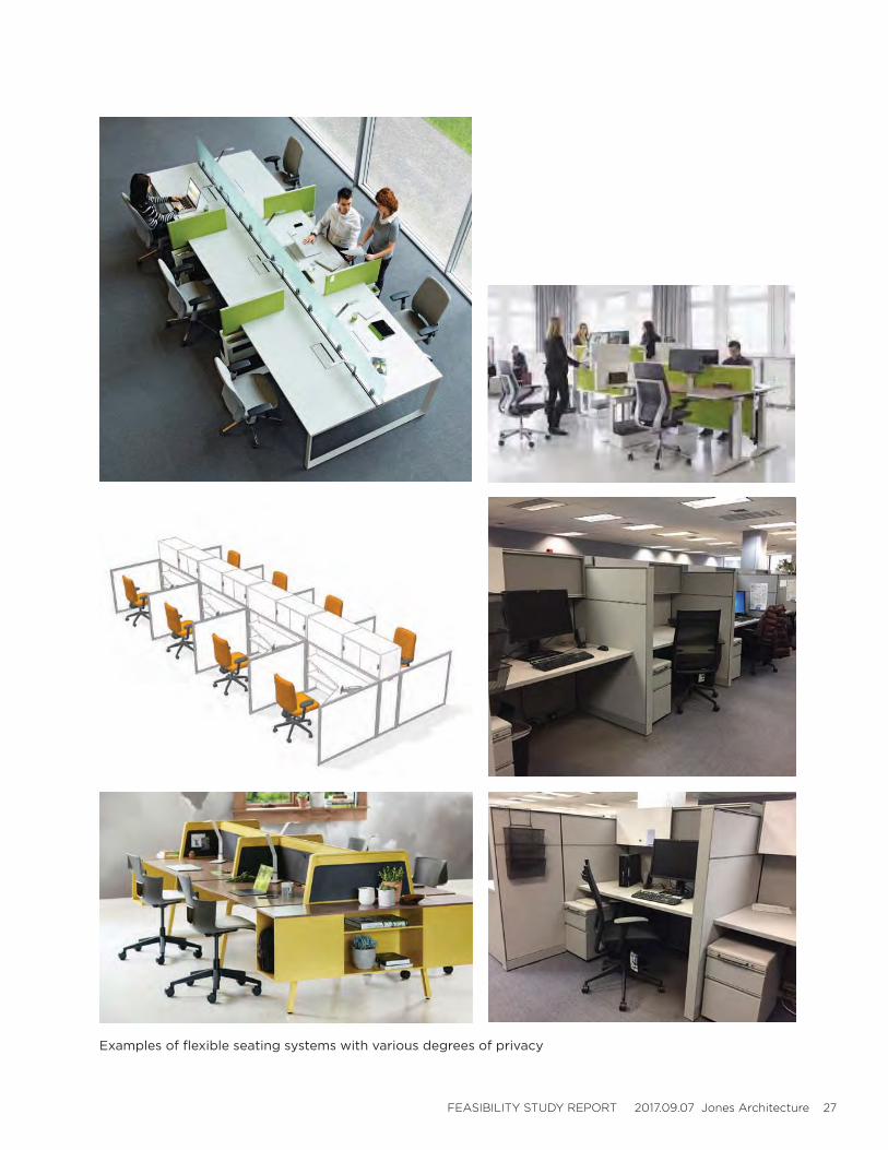
As discussed with regard to the Seasonal staff area above, there is the possibility of utilizing a less permanent desking solution than cubicles. The general consensus is that each desk must be large enough to house a staff member as well as an instructor for an extended period of time, and must also have a certain degree of acoustic privacy. An open benching strategy would not work. On the next page there are a series of furniture images to be discussed as possible solutions during the next phase of study. Additionally, the design team will explore the use of sit-to-stand desks, also pictured.
Update: upon further discussion DUA believes that individual cubicles similar to those used in the Claims Department are the most appropriate seating strategy for Seasonal employees. Even though Seasonal employees are temporary, their desks should not intentionally reflect this difference from the Call Center employees. The issue should only be revisited if space constraints demand a different seating approach in the design phase.
FEASIBILITY STUDY REPORT 2017.09.07 Jones Architecture 27
Examples of flexible seating systems with various degrees of privacy
28 Department of Unemployment Assistance, Brockton MA. DCAMM DCP1722 HS1
D. FEASIBILITY ANALYSIS

FEASIBILITY STUDY REPORT 2017.09.07 Jones Architecture 29
30 Department of Unemployment Assistance, Brockton MA. DCAMM DCP1722 HS1
D. FEASIBILITY ANALYSIS
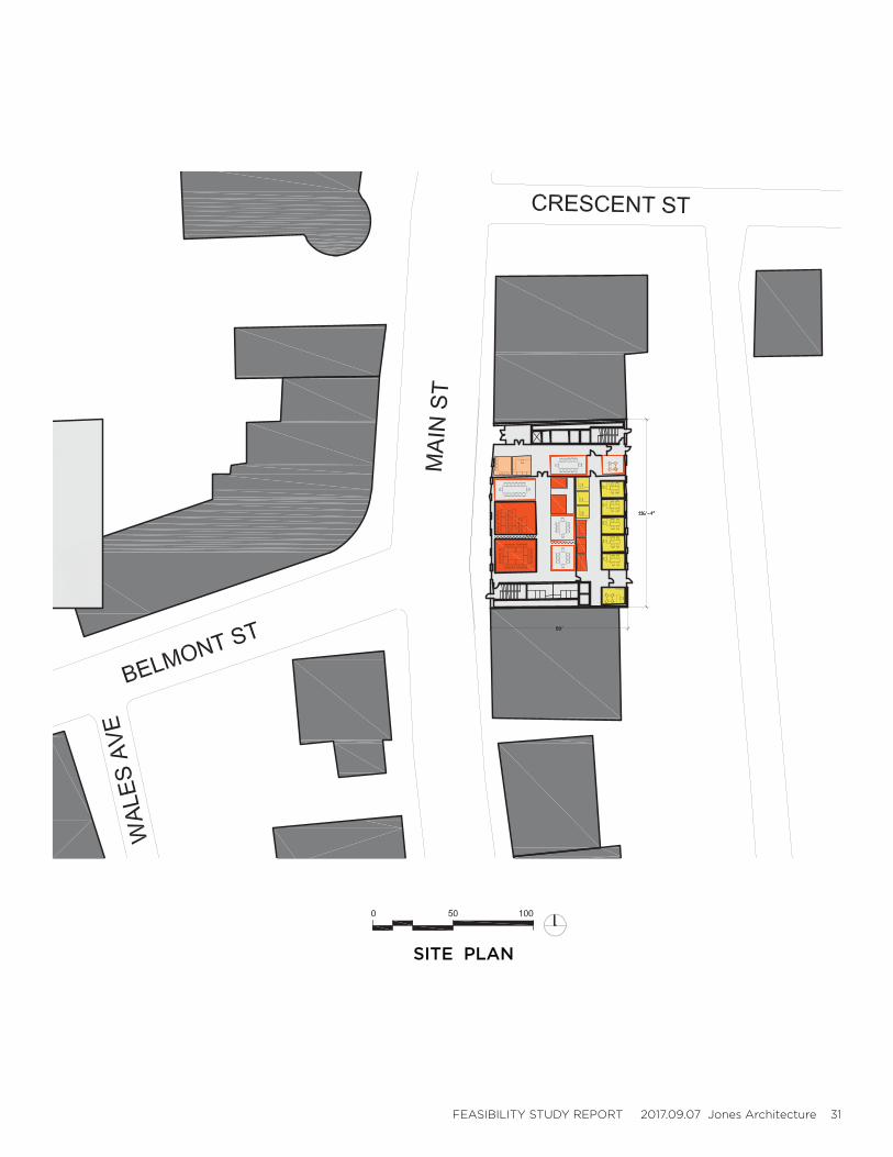
SITE PLAN
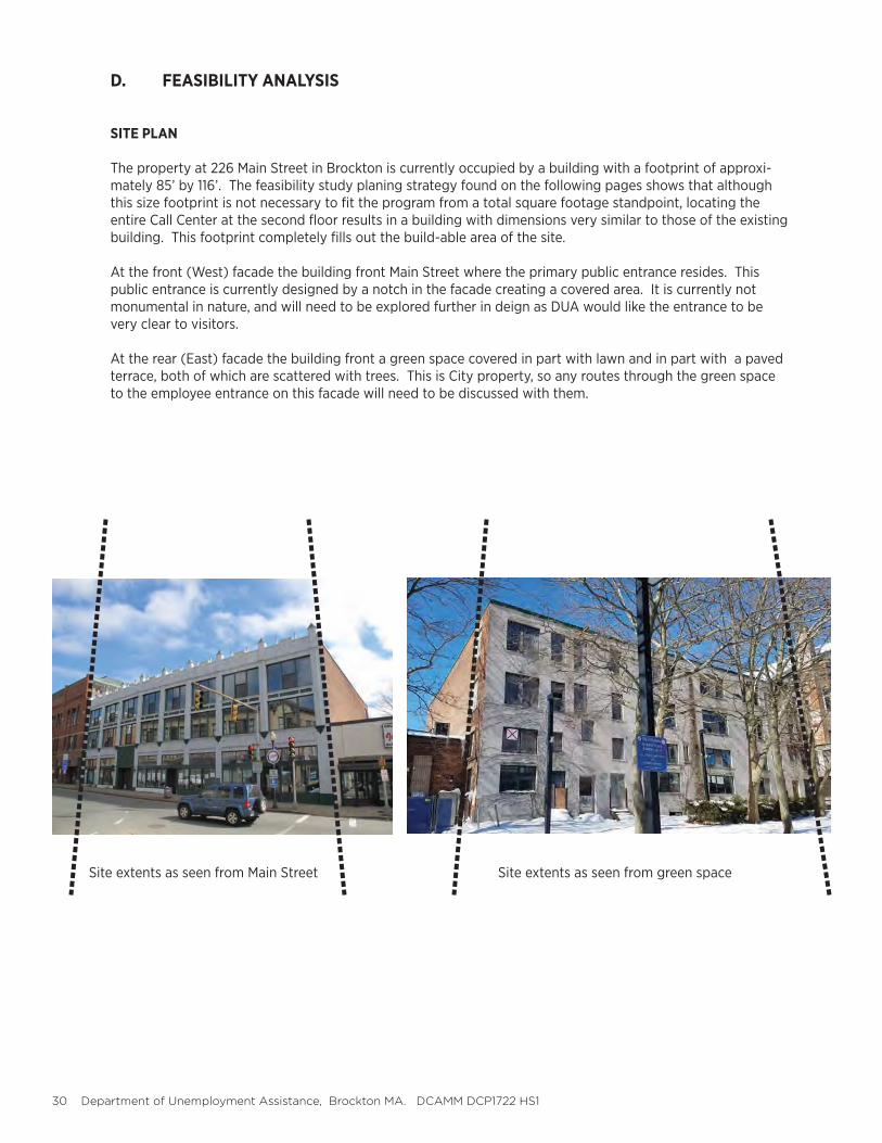
The property at 226 Main Street in Brockton is currently occupied by a building with a footprint of approxi-mately 85’ by 116’. The feasibility study planing strategy found on the following pages shows that although this size footprint is not necessary to fit the program from a total square footage standpoint, locating the entire Call Center at the second floor results in a building with dimensions very similar to those of the existing building. This footprint completely fills out the build-able area of the site.
At the front (West) facade the building front Main Street where the primary public entrance resides. This public entrance is currently designed by a notch in the facade creating a covered area. It is currently not monumental in nature, and will need to be explored further in deign as DUA would like the entrance to be very clear to visitors.
At the rear (East) facade the building front a green space covered in part with lawn and in part with a paved terrace, both of which are scattered with trees. This is City property, so any routes through the green space to the employee entrance on this facade will need to be discussed with them.
Site extents as seen from Main Street Site extents as seen from green space
FEASIBILITY STUDY REPORT 2017.09.07 Jones Architecture 31
SITE PLAN
32 Department of Unemployment Assistance, Brockton MA. DCAMM DCP1722 HS1
D. FEASIBILITY ANALYSIS
PREFERRED ALTERNATIVE SUMMARY
The design team undertook a planning effort as part of the Feasibility Analysis, developing four unique strategies for DCAMM and DUA review. This planning effort can be found in the Appendix. These planning iterations led to the development of some critical strategies, below, and ultimately to the preferred Feasibility Planning Strategy found on the following pages.
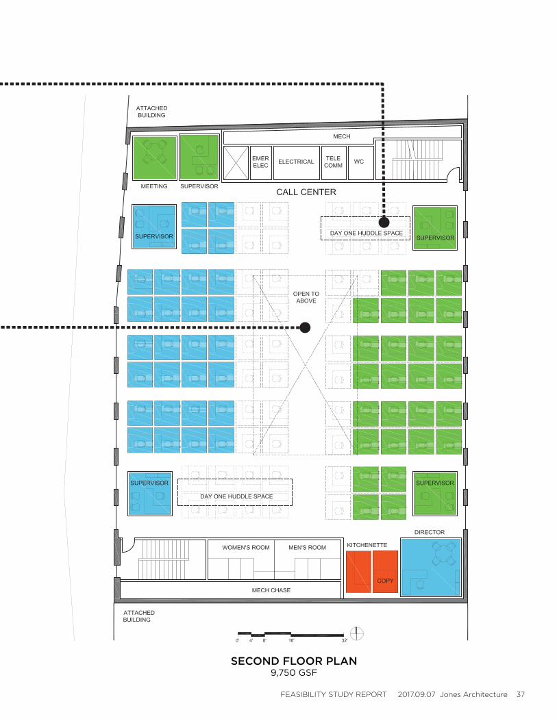
1. Call Center is to be located completely at one floor. Early schemes had the two components of the Call Center, Claims and Adjudication, split between floors to minimize the overall building footprint. It was determined that locating all of these desks at one floor is preferred, and possible from a planning standpoint if the building footprint is maximized to cover the entire site. This single move has a dramatic effect on the overall size of the building, leading to additional unassigned program space. The Call Center should not be located at street level, and should be secure on an upper floor due to the sensitive employment information that is exchange din this space.
2. Day one Cell Center staffing. The total number of Call Center cubicles (96) includes (55) currently occu-pied desks and (41) currently unoccupied. It is possible that the economy will dictate more employees be hired between now and when this building is completed, however if desks remain open DUA will be able to think about alternate program elements with in the Call Center. Huddlespaces are suggested on the plans, with could easily be defined by ceiling treatment or furniture. This temporary space will need to be studied further in design.
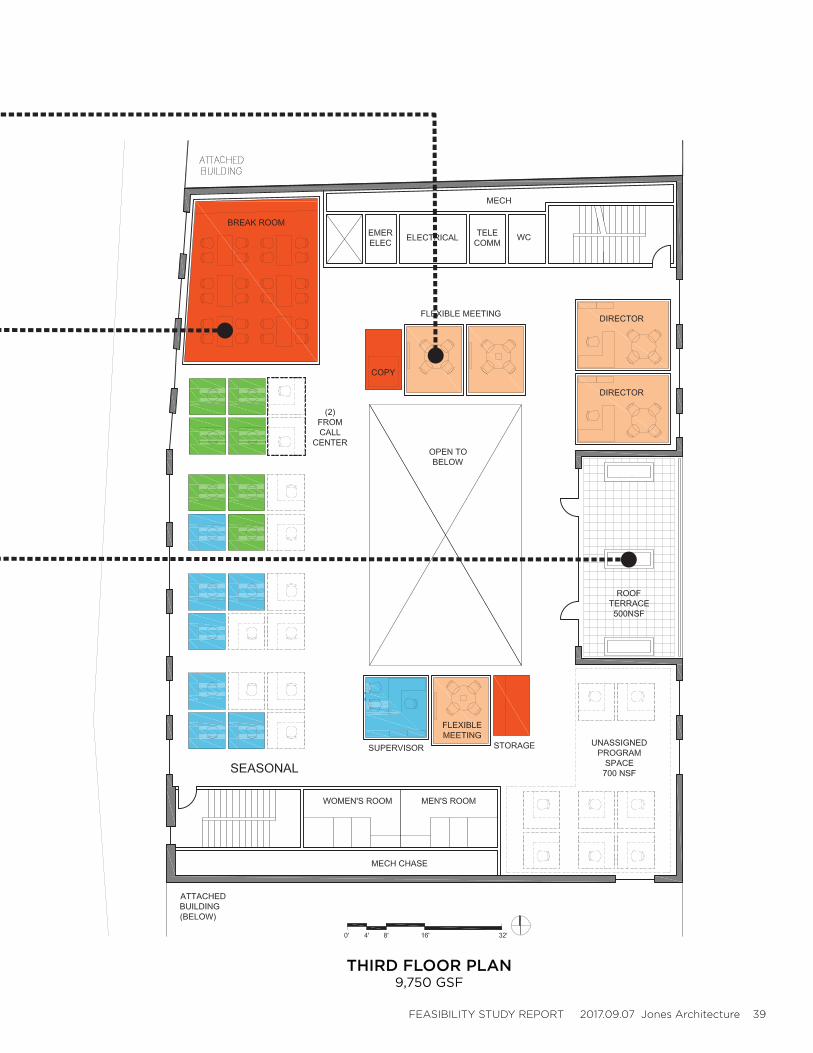
3. Unassigned program space. The footprint required to accommodate all of the Call Center at the second floor results in unassigned program space at both the first and third floors. At the appropriate program infill is considered to be shared meeting and conference space, see further description below. At the third floor the appropriate program infill is considered to be additional call center growth space. Unassigned program space is to be studied further during the Certifiable Building Study.
4. Shared program space located at first floor. These program elements include Training Room, Conference Room, and various smaller meeting spaces. It was determined during the planning exercise that these spaces are best located at the street level. This position in the building could potentially facilitate usage by other state entities, and are the least sensitive from a security standpoint.
5. Hearings department located at the first floor. The Hearings department is the only portion of DUA that interfaces with the public, as such it makes the most sense to also locate this program at street level. Hear-ings cases can become contentious, as such review examiner offices should have windows into them, panic buttons, and the examiner to have his or her back to the door. In addition the Hearings department should have its own restroom so review examiners do not need to use public restrooms.
6. Employee environmental experience to be elevated. Due to the depth of the floor plate there is both an need and an opportunity to deliver natural light to he middle of the plan via a light monitor. An open to be-low space at the third floor will allow natural light to spill down to Call Center at second floor. Large windows at both front (West) and rear (East) facades will also help to get natural light deeper into the plan as well as affording views to exterior. An exterior terrace/roof garden has been included at the third floor to give employees a place to spend their break time, locates at the East facade, overlooking a green space.
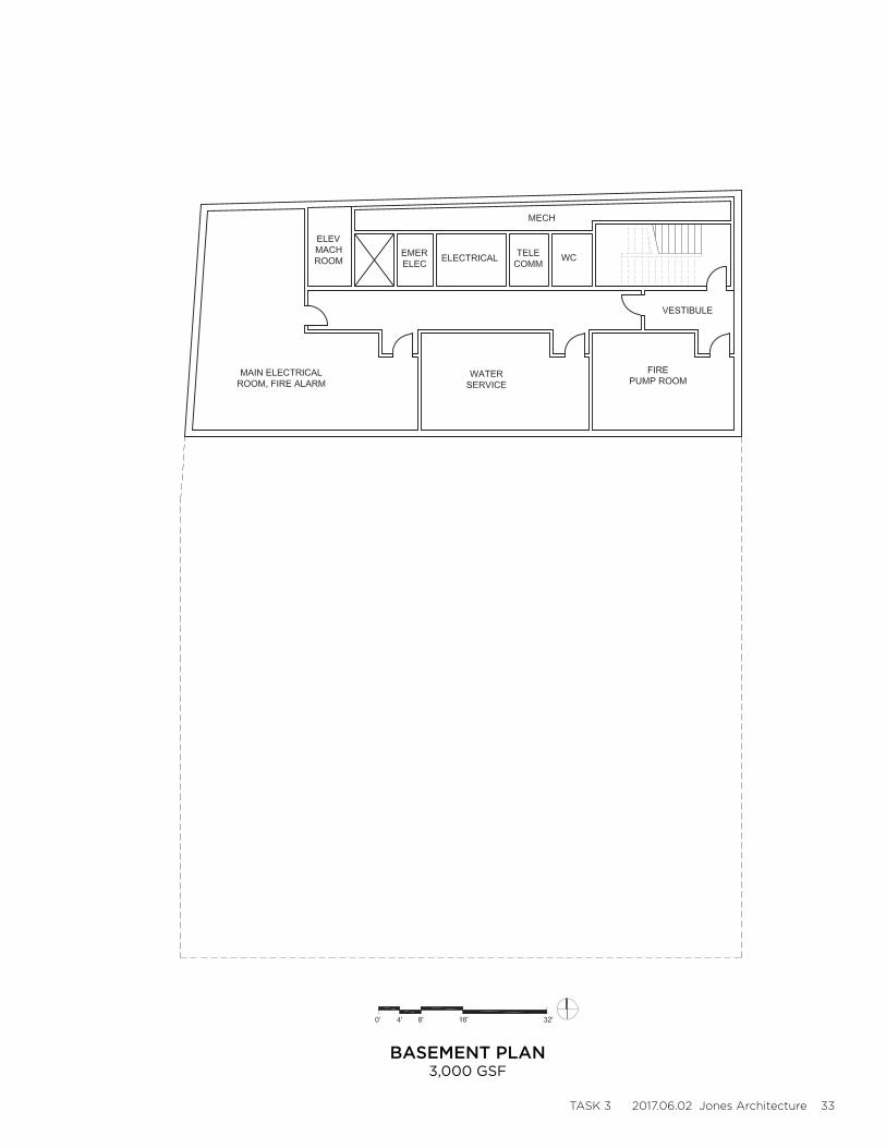
7. The building systems will reside at the basement and roof levels, with chases running along the north and south party walls to feed the intermediate floors. The basement has a very small footprint relative to the floors above which will result in a strategy where the existing basement on site will need to be infilled. See building systems narratives in this report for additional details.
TASK 3 2017.06.02 Jones Architecture 33
BASEMENT PLAN3,000 GSF
34 Department of Unemployment Assistance, Brockton MA. DCAMM DCP1722 HS1
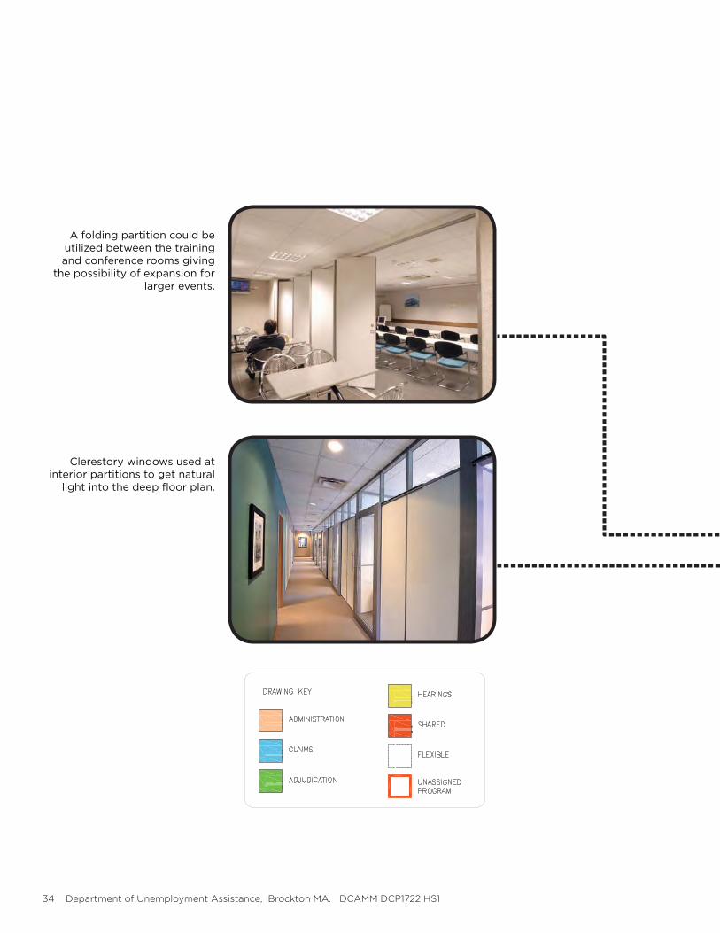
A folding partition could be utilized between the training and conference rooms giving
the possibility of expansion for larger events.
Clerestory windows used at interior partitions to get natural
light into the deep floor plan.

FEASIBILITY STUDY REPORT 2017.09.07 Jones Architecture 35
FIRST FLOOR PLAN9,750 GSF
36 Department of Unemployment Assistance, Brockton MA. DCAMM DCP1722 HS1
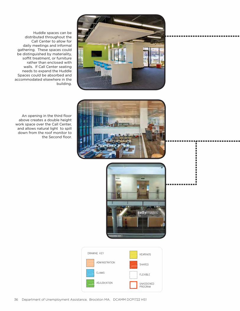
An opening in the third floor above creates a double height
work space over the Call Center, and allows natural light to spill down from the roof monitor to
the Second floor.
Huddle spaces can be distributed throughout the
Call Center to allow for daily meetings and informal
gathering. These spaces could be distinguished by materiality,
soffit treatment, or furniture rather than enclosed with
walls. If Call Center seating needs to expand the Huddle
Spaces could be absorbed and accommodated elsewhere in the
building.
FEASIBILITY STUDY REPORT 2017.09.07 Jones Architecture 37
SECOND FLOOR PLAN9,750 GSF
38 Department of Unemployment Assistance, Brockton MA. DCAMM DCP1722 HS1
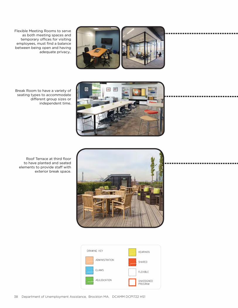
Flexible Meeting Rooms to serve as both meeting spaces and
temporary offices for visiting employees, must find a balance
between being open and having adequate privacy..
Break Room to have a variety of seating types to accommodate
different group sizes or independent time.
Roof Terrace at third floor to have planted and seated
elements to provide staff with exterior break space.
FEASIBILITY STUDY REPORT 2017.09.07 Jones Architecture 39
THIRD FLOOR PLAN9,750 GSF
40 Department of Unemployment Assistance, Brockton MA. DCAMM DCP1722 HS1
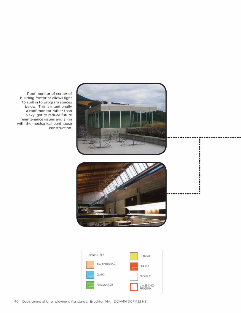
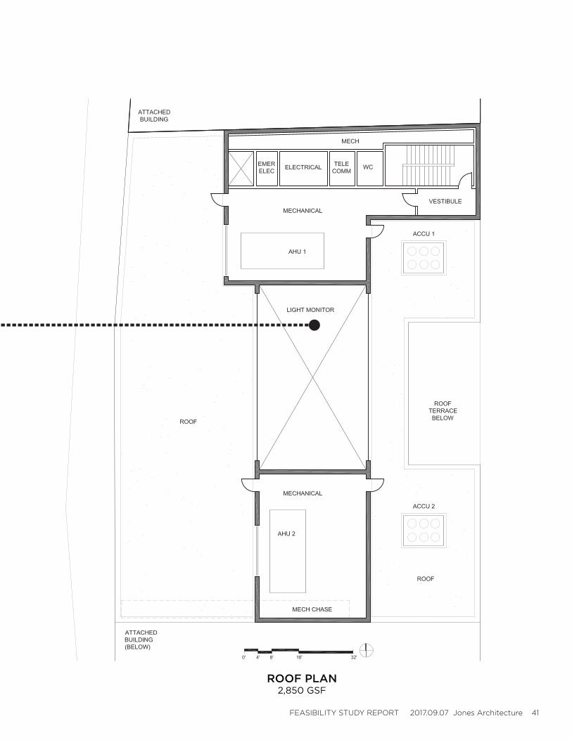
Roof monitor of center of building footprint allows light to spill in to program spaces
below. This is intentionally a roof monitor rather than a skylight to reduce future
maintenance issues and align with the mechanical penthouse
construction.
FEASIBILITY STUDY REPORT 2017.09.07 Jones Architecture 41
ROOF PLAN2,850 GSF
42 Department of Unemployment Assistance, Brockton MA. DCAMM DCP1722 HS1
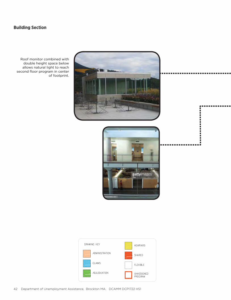
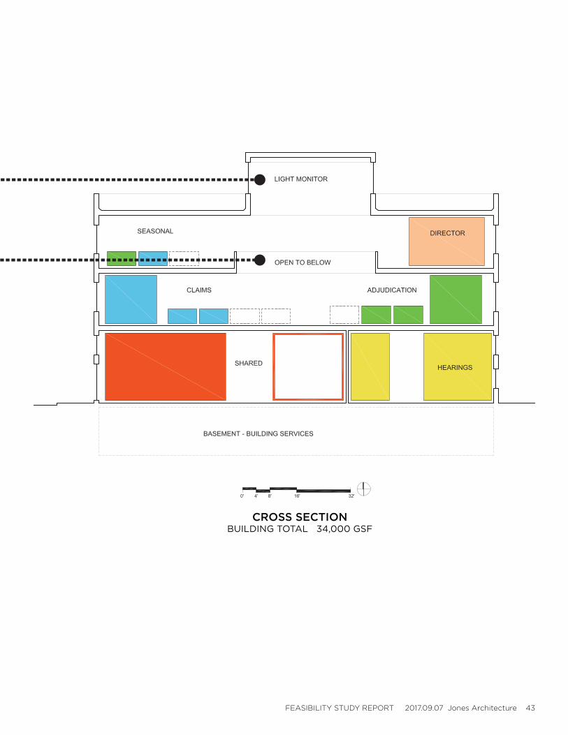
Roof monitor combined with double height space below allows natural light to reach
second floor program in center of footprint.
Building Section
FEASIBILITY STUDY REPORT 2017.09.07 Jones Architecture 43
CROSS SECTIONBUILDING TOTAL 34,000 GSF
44 Department of Unemployment Assistance, Brockton MA. DCAMM DCP1722 HS1
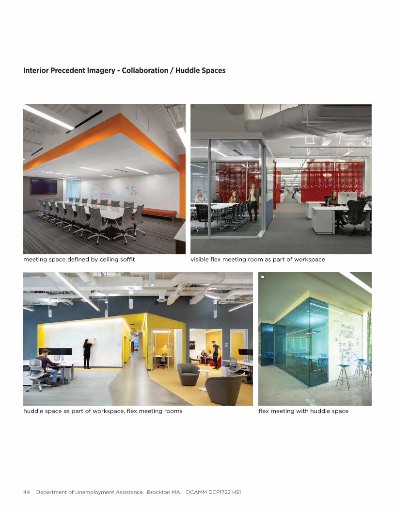
Interior Precedent Imagery - Collaboration / Huddle Spaces
meeting space defined by ceiling soffit
huddle space as part of workspace, flex meeting rooms
visible flex meeting room as part of workspace
flex meeting with huddle space
FEASIBILITY STUDY REPORT 2017.09.07 Jones Architecture 45
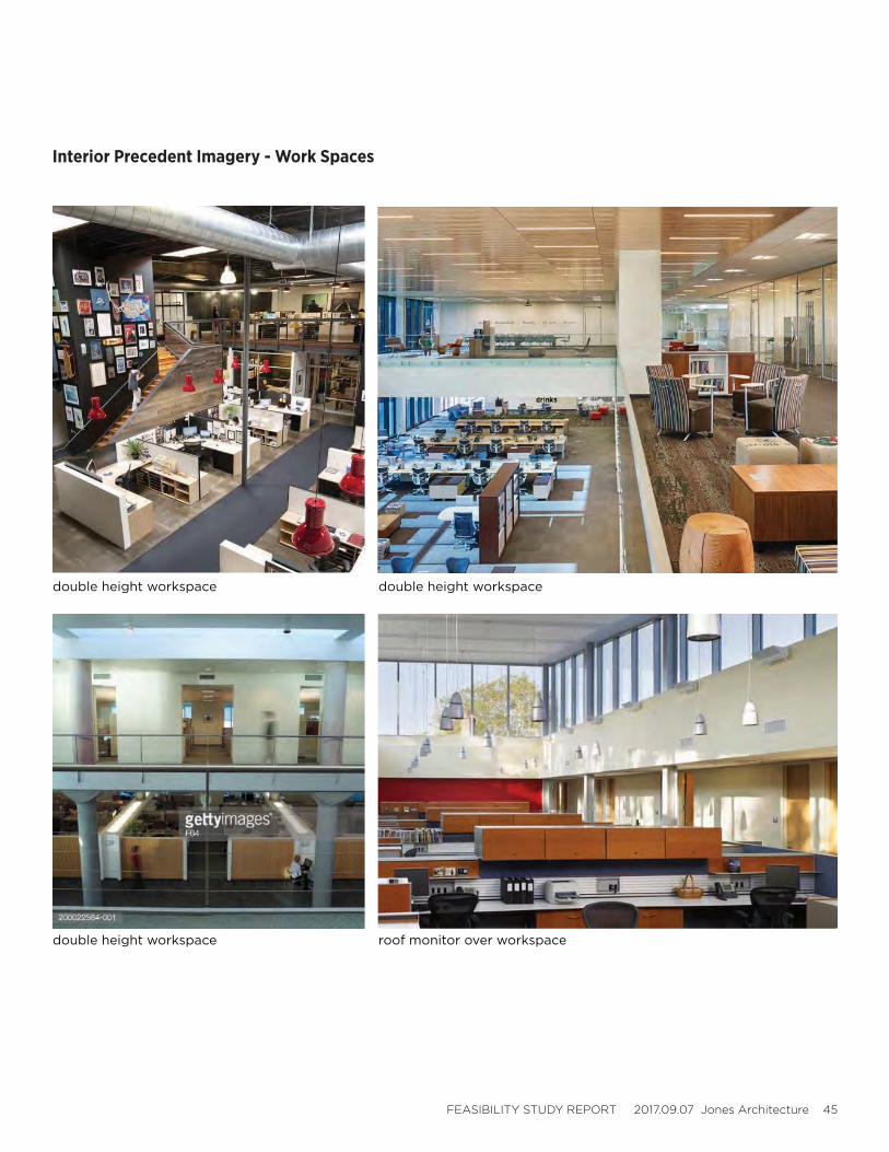
Interior Precedent Imagery - Work Spaces
double height workspace double height workspace
roof monitor over workspacedouble height workspace
46 Department of Unemployment Assistance, Brockton MA. DCAMM DCP1722 HS1
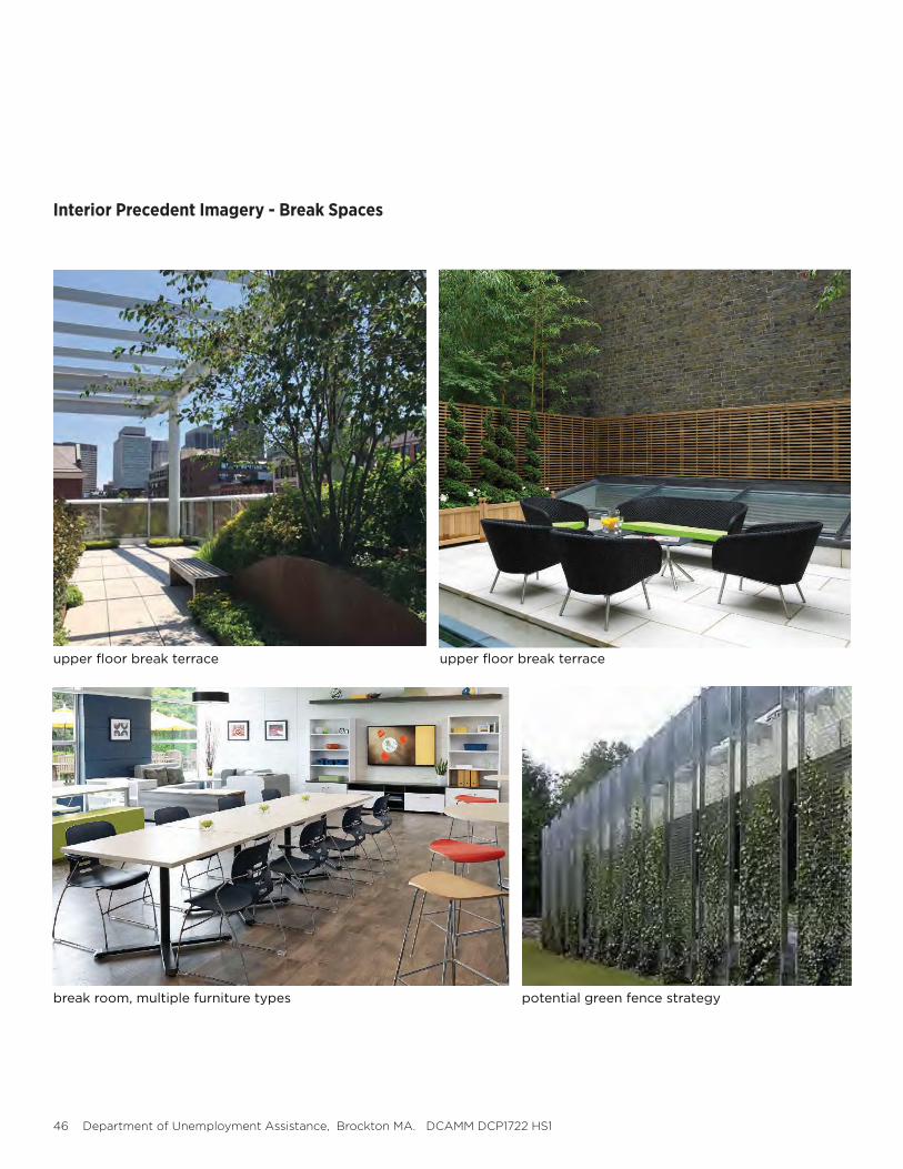
Interior Precedent Imagery - Break Spaces
upper floor break terrace
break room, multiple furniture types potential green fence strategy
upper floor break terrace

FEASIBILITY STUDY REPORT 2017.09.07 Jones Architecture 47
48 Department of Unemployment Assistance, Brockton MA. DCAMM DCP1722 HS1
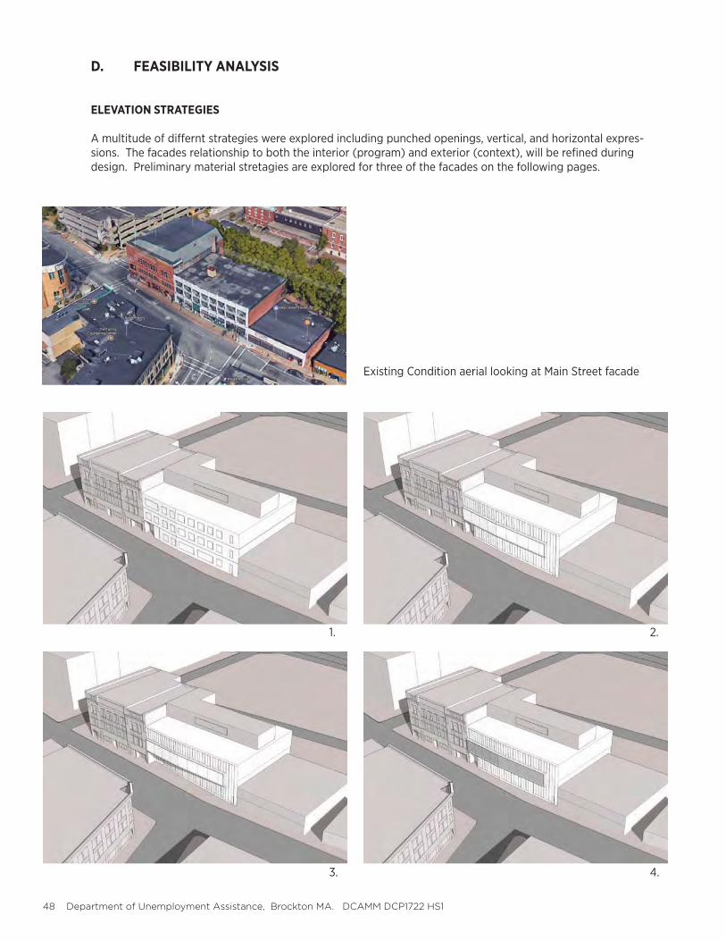
D. FEASIBILITY ANALYSIS
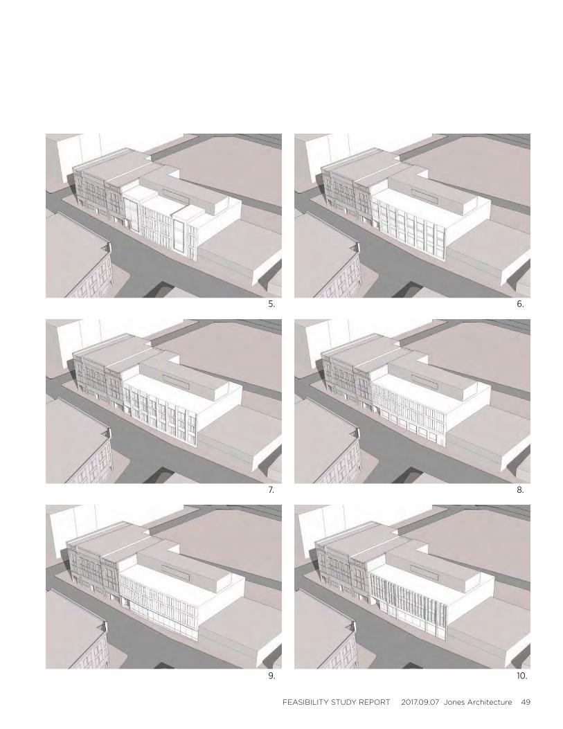
ELEVATION STRATEGIES
A multitude of differnt strategies were explored including punched openings, vertical, and horizontal expres-sions. The facades relationship to both the interior (program) and exterior (context), will be refined during design. Preliminary material stretagies are explored for three of the facades on the following pages.
1. 2.
3. 4.
Existing Condition aerial looking at Main Street facade
FEASIBILITY STUDY REPORT 2017.09.07 Jones Architecture 49
7. 8.
9. 10.
5. 6.
50 Department of Unemployment Assistance, Brockton MA. DCAMM DCP1722 HS1
D. FEASIBILITY ANALYSIS
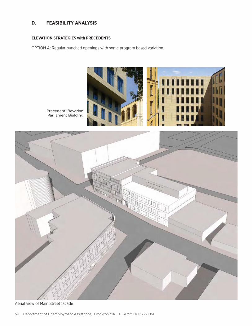
ELEVATION STRATEGIES with PRECEDENTS
OPTION A: Regular punched openings with some program based variation.
Aerial view of Main Street facade
Precedent: Bavarian Parliament Building

FEASIBILITY STUDY REPORT 2017.09.07 Jones Architecture 51
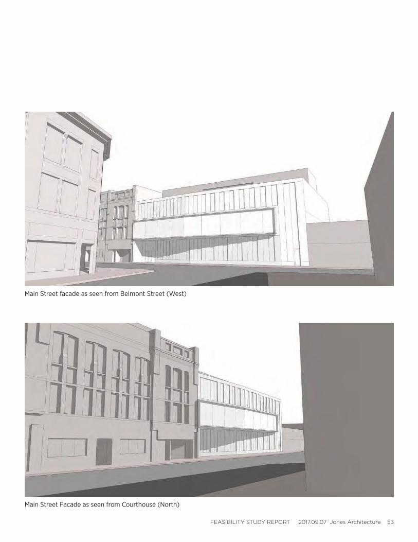
Main Street facade as seen from Belmont Street (West)
Main Street Facade as seen from Courthouse (North)
52 Department of Unemployment Assistance, Brockton MA. DCAMM DCP1722 HS1
D. FEASIBILITY ANALYSIS
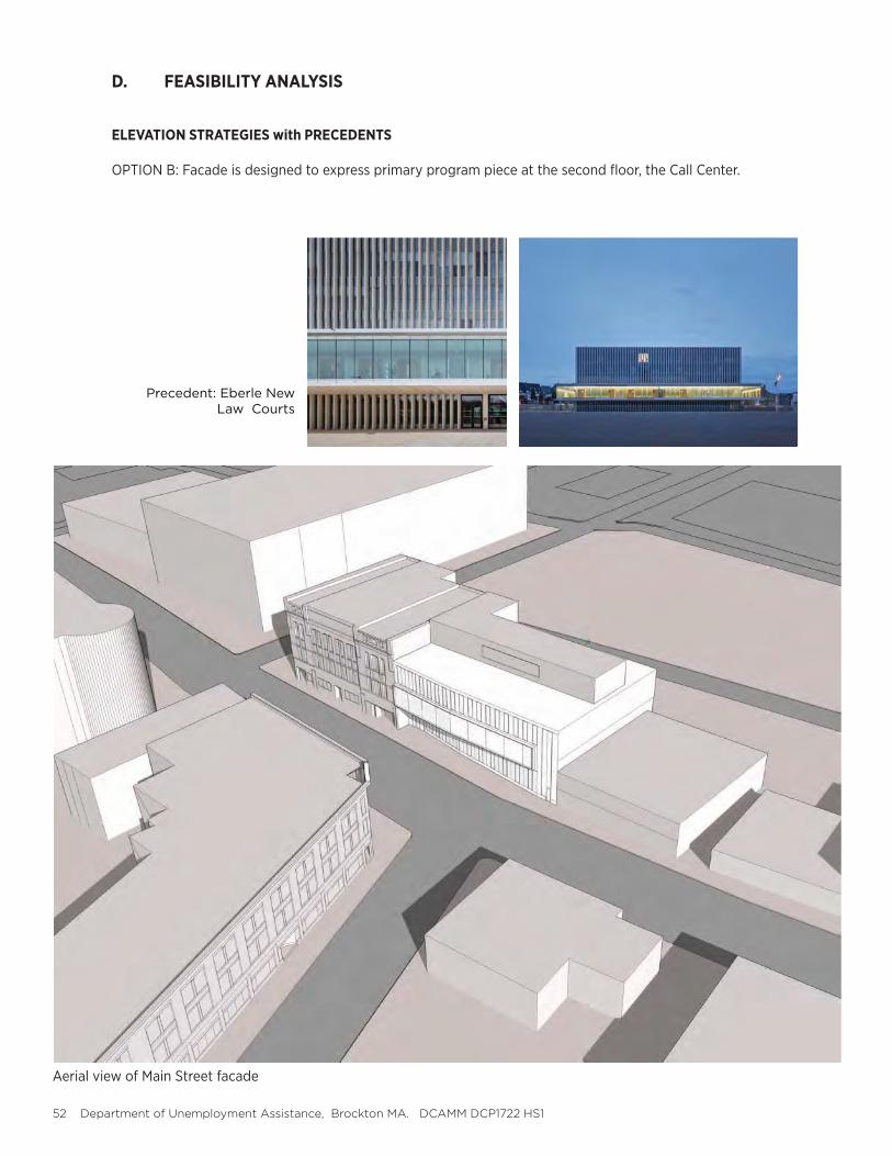
ELEVATION STRATEGIES with PRECEDENTS
OPTION B: Facade is designed to express primary program piece at the second floor, the Call Center.
Aerial view of Main Street facade
Precedent: Eberle New Law Courts
FEASIBILITY STUDY REPORT 2017.09.07 Jones Architecture 53
Main Street facade as seen from Belmont Street (West)
Main Street Facade as seen from Courthouse (North)
54 Department of Unemployment Assistance, Brockton MA. DCAMM DCP1722 HS1
D. FEASIBILITY ANALYSIS
ELEVATION STRATEGIES with PRECEDENTS
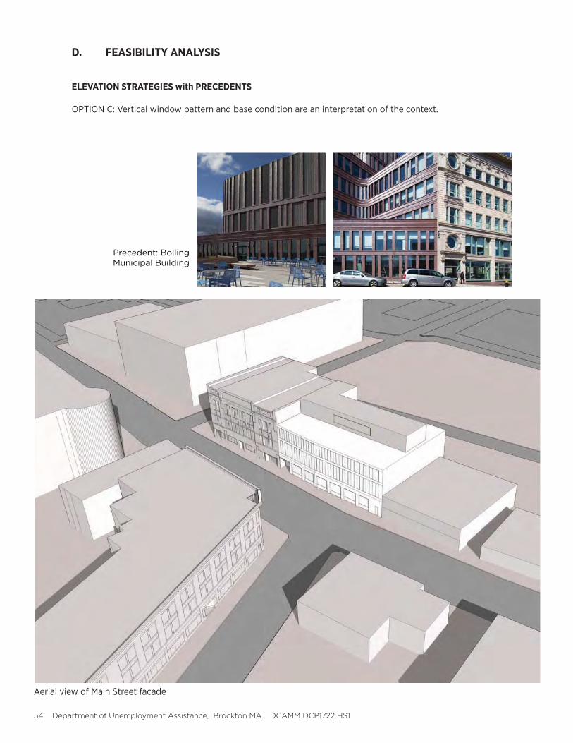
OPTION C: Vertical window pattern and base condition are an interpretation of the context.
Aerial view of Main Street facade
Precedent: Bolling Municipal Building
FEASIBILITY STUDY REPORT 2017.09.07 Jones Architecture 55
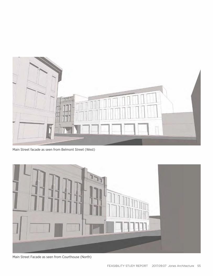
Main Street facade as seen from Belmont Street (West)
Main Street Facade as seen from Courthouse (North)
56 Department of Unemployment Assistance, Brockton MA. DCAMM DCP1722 HS1
D. FEASIBILITY ANALYSIS
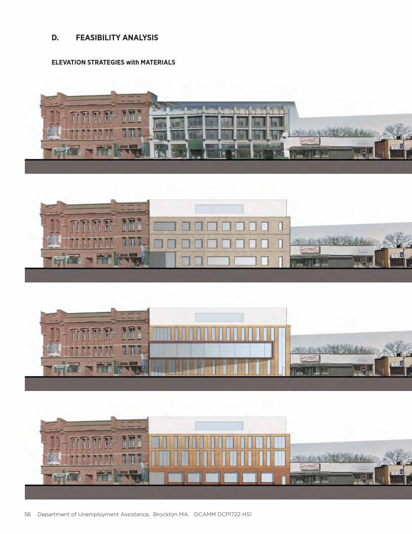
ELEVATION STRATEGIES with MATERIALS
FEASIBILITY STUDY REPORT 2017.09.07 Jones Architecture 57
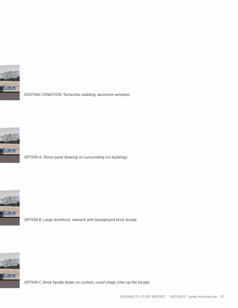
OPTION A: Stone panel drawing on surrounding civi buildings.
OPTION B: Large storefront element with background brick facade.
OPTION C: Brick facade draws on context, could chage color up the facade.
EXISTING CONDITION: Terracotta cladding, aluminum windows.
58 Department of Unemployment Assistance, Brockton MA. DCAMM DCP1722 HS1
E. PRELIMINARY SUSTAINABILITY STRATEGIES
F. REGULATORY ANALYSIS

FEASIBILITY STUDY REPORT 2017.09.07 Jones Architecture 59
60 Department of Unemployment Assistance, Brockton MA. DCAMM DCP1722 HS1
E. PRELIMINARY SUSTAINABILITY STRATEGIES
The following criteria are to be met per Executive Order 484. If building construction extends into 2020 the criteria in parentheses are to be targeted.
1. Reduce Greenhouse gas emissions by 25% from baseline 2002 building, absolute basis. (40% reduction by 2020).
2. Reduce overall energy consumption by 20% from baseline 2004 building, BTUs per SF. (35% reduction by 2020).
3. Procure 15% of energy via renewable sources. (30% by 2020).
4. Utilize 10% bio heat blend for heating fuel.
5. Meet Mass LEED Plus (2006 regulations)
1.1 Large Projects
All executive agencies shall adhere to the newly created “Massachusetts LEED Plus” stan-dard for projects that are 20,000 square feet or larger and designed for use by a public entity.
Massachusetts LEED Plus requires obtaining the basic LEED certification and attainment of the following specific LEED credits:
1.1.1 Energy performance exceeding Massachusetts Energy Code requirements by at least 20 percent (LEED-NC Version 2.2, Energy & Atmosphere, Credit 1).
1.1.2 Third party building commissioning (LEED-NC Version 2.2, Energy & Atmosphere,Prerequisite 1, Credit 3).
1.1.3 At least one of the four following Smart Growth criteria (unless the criteria con-flict with another critical public policy objective):
a) Construct or renovate on a previously developed site (LEED-NC Version 2.2 Sustainable Sites, Credit 2) - In a community with a minimum density of 60,000 square feet per acre or- Within one-half mile of ten basic services and a residential zone or neighbor-hood with an average density of ten units per acre; and with pedestrian access between buildings and services.
b) Construct or renovate on a brownfields site (LEED-NC Version 2.2, Sustain-able Sites, Credit 3).
c) Construct or renovate on a site with public transportation (train or bus) within one half mile (LEED-NC Version 2.2, Sustainable Sites, Credit 4.1).
d) Maintain 75 percent of existing building structure and envelope (LEED-NC Version 2.2, Materials and Resources, Credit 1.1).
1.1.4 Two irrigation and building water efficiency criteria:
a) Reduce potable water consumption for irrigation by 50 percent (LEED-NC Version 2.2, Water Efficiency, Credit 1.1). b) Incorporate strategies that will conserve 20 percent of building water use (LEEDNC Version 2.2, Water Efficiency, Credit 3.1).
6. Reduce potable water use by 10% from baseline 2006. (15% by 2020).
FEASIBILITY STUDY REPORT 2017.09.07 Jones Architecture 61
F. REGULATORY ANALYSIS
Assigned State Building Inspector and Plumbing inspector are be engaged during the design process to make sure the design strategy and documentation are meeting nec-essary requirements.
Brockton Fire Department to be engaged to ensure local Fire Codes are being met.
All design drawings and specifications for this project will be submitted for state building permit electronically. Details of the submission will be discussed with assigned inspector and may include such documents as Construction Control Affidavits and Required inspections Checklist.
Processing of State building permit application and Brockton Fire Department review is estimated to take about 1 month after completion of the permit documents, this time is built into the schedule.
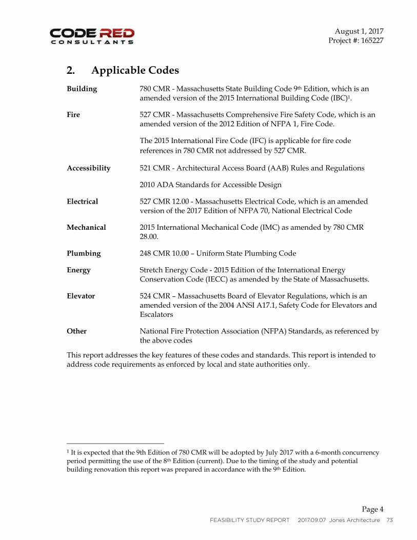
The following codes are to followed during the design of this building:
Building: 780 CMR - Massachusetts State Building Code 9th Edition, which is an amended ver-sion of the 2015 International Building Code (IBC)1.
Fire:527 CMR - Massachusetts Comprehensive Fire Safety Code, which is an amended version of the 2012 Edition of NFPA 1, Fire Code.
The 2015 International Fire Code (IFC) is applicable for fire code references in 780 CMR not addressed by 527 CMR.
Accessibility: 521 CMR - Architectural Access Board (AAB) Rules and Regulations 2010 ADA Standards for Accessible Design
Electrical: 527 CMR 12.00 - Massachusetts Electrical Code, which is an amended version of the 2017 Edition of NFPA 70, National Electrical Code
Mechanical: 2015 International Mechanical Code (IMC) as amended by 780 CMR 28.00.
Plumbing: 248 CMR 10.00 – Uniform State Plumbing Code
Energy: Stretch Energy Code - 2015 Edition of the International Energy Conservation Code (IECC) as amended by the State of Massachusetts.
Elevator:
524 CMR – Massachusetts Board of Elevator Regulations, which is an amended ver-sion of the 2004 ANSI A17.1, Safety Code for Elevators and Escalators
Other:National Fire Protection Association (NFPA) Standards, as referenced by the above codes
62 Department of Unemployment Assistance, Brockton MA. DCAMM DCP1722 HS1
G. ITEMS FOR FURTHER STUDY

FEASIBILITY STUDY REPORT 2017.09.07 Jones Architecture 63
64 Department of Unemployment Assistance, Brockton MA. DCAMM DCP1722 HS1
G. ITEMS FOR FURTHER STUDY
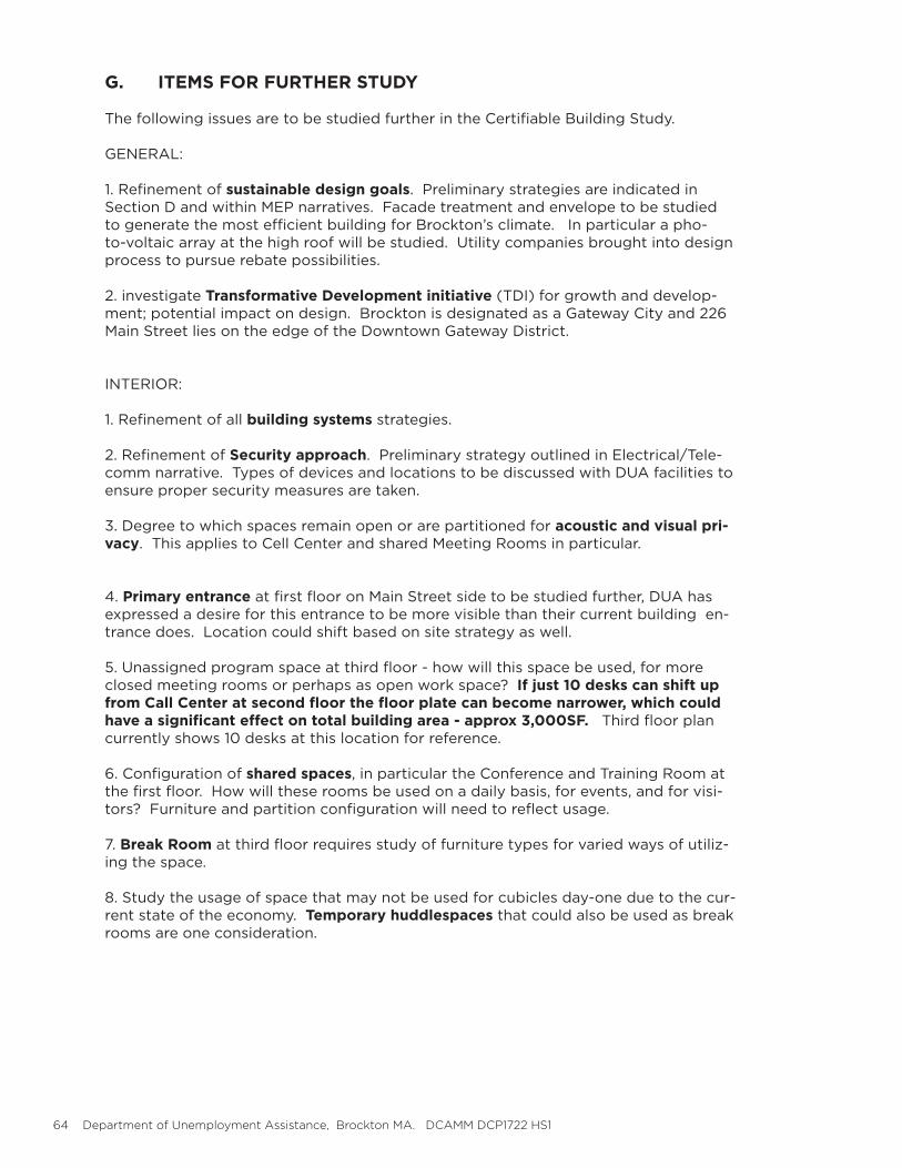
The following issues are to be studied further in the Certifiable Building Study.
GENERAL:
1. Refinement of sustainable design goals. Preliminary strategies are indicated in Section D and within MEP narratives. Facade treatment and envelope to be studied to generate the most efficient building for Brockton’s climate. In particular a pho-to-voltaic array at the high roof will be studied. Utility companies brought into design process to pursue rebate possibilities.
2. investigate Transformative Development initiative (TDI) for growth and develop-ment; potential impact on design. Brockton is designated as a Gateway City and 226 Main Street lies on the edge of the Downtown Gateway District.
INTERIOR:
1. Refinement of all building systems strategies.
2. Refinement of Security approach. Preliminary strategy outlined in Electrical/Tele-comm narrative. Types of devices and locations to be discussed with DUA facilities to ensure proper security measures are taken.
3. Degree to which spaces remain open or are partitioned for acoustic and visual pri-vacy. This applies to Cell Center and shared Meeting Rooms in particular.
4. Primary entrance at first floor on Main Street side to be studied further, DUA has expressed a desire for this entrance to be more visible than their current building en-trance does. Location could shift based on site strategy as well.
5. Unassigned program space at third floor - how will this space be used, for more closed meeting rooms or perhaps as open work space? If just 10 desks can shift up from Call Center at second floor the floor plate can become narrower, which could have a significant effect on total building area - approx 3,000SF. Third floor plan currently shows 10 desks at this location for reference.
6. Configuration of shared spaces, in particular the Conference and Training Room at the first floor. How will these rooms be used on a daily basis, for events, and for visi-tors? Furniture and partition configuration will need to reflect usage.
7. Break Room at third floor requires study of furniture types for varied ways of utiliz-ing the space.
8. Study the usage of space that may not be used for cubicles day-one due to the cur-rent state of the economy. Temporary huddlespaces that could also be used as break rooms are one consideration.
FEASIBILITY STUDY REPORT 2017.09.07 Jones Architecture 65
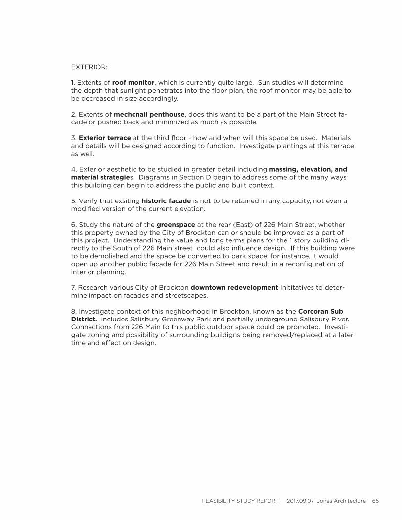
EXTERIOR:
1. Extents of roof monitor, which is currently quite large. Sun studies will determine the depth that sunlight penetrates into the floor plan, the roof monitor may be able to be decreased in size accordingly.
2. Extents of mechcnail penthouse, does this want to be a part of the Main Street fa-cade or pushed back and minimized as much as possible.
3. Exterior terrace at the third floor - how and when will this space be used. Materials and details will be designed according to function. Investigate plantings at this terrace as well.
4. Exterior aesthetic to be studied in greater detail including massing, elevation, and material strategies. Diagrams in Section D begin to address some of the many ways this building can begin to address the public and built context.
5. Verify that exsiting historic facade is not to be retained in any capacity, not even a modified version of the current elevation.
6. Study the nature of the greenspace at the rear (East) of 226 Main Street, whether this property owned by the City of Brockton can or should be improved as a part of this project. Understanding the value and long terms plans for the 1 story building di-rectly to the South of 226 Main street could also influence design. If this building were to be demolished and the space be converted to park space, for instance, it would open up another public facade for 226 Main Street and result in a reconfiguration of interior planning.
7. Research various City of Brockton downtown redevelopment Inititatives to deter-mine impact on facades and streetscapes.
8. Investigate context of this neghborhood in Brockton, known as the Corcoran Sub District. includes Salisbury Greenway Park and partially underground Salisbury River. Connections from 226 Main to this public outdoor space could be promoted. Investi-gate zoning and possibility of surrounding buildigns being removed/replaced at a later time and effect on design.

66 Department of Unemployment Assistance, Brockton MA. DCAMM DCP1722 HS1
H. SYSTEMS NARRATIVES

FEASIBILITY STUDY REPORT 2017.09.07 Jones Architecture 67
68 Department of Unemployment Assistance, Brockton MA. DCAMM DCP1722 HS1
H. SYSTEMS NARRATIVES
INTRODUCTION
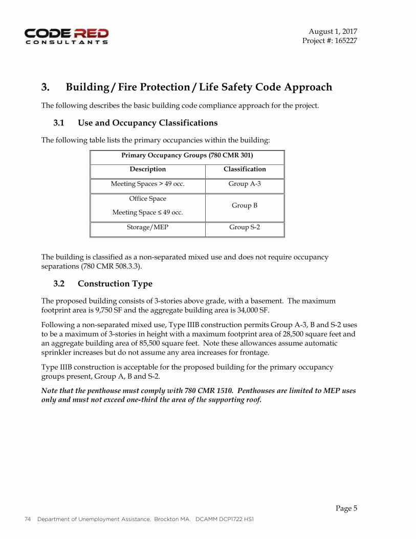
CODE ANALYSIS1. New Building, Type III construction permits Group B and S-2 uses to be a maximum 4 stories with building area of 57,000 SF and floor plate of 14,250SF. 2. Applicable codes found in Section E.3. Building to meet code in its entirety including being fully accessible.
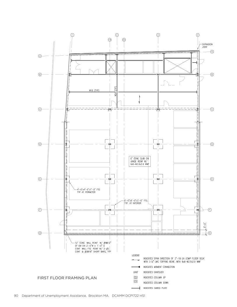
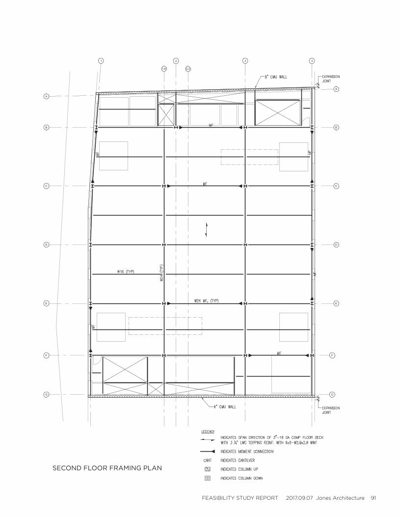
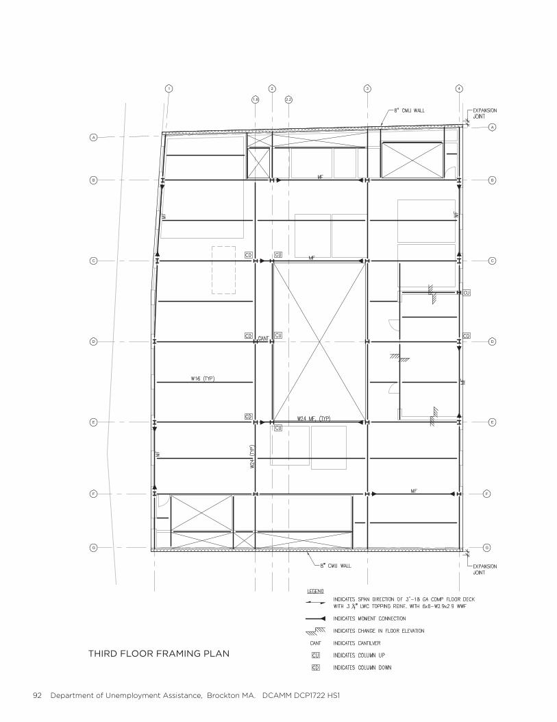
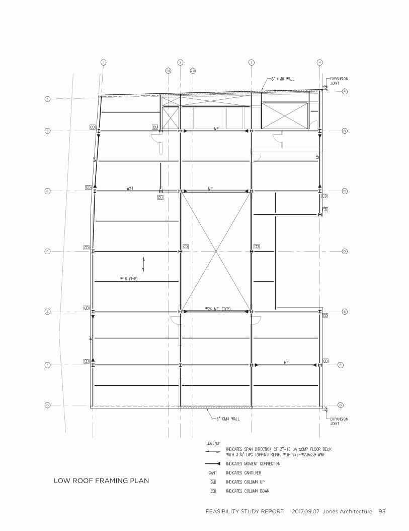
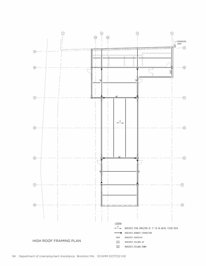
STRUCTURAL1. All new structure to meet code. 2. Assuming: concrete footings/foundations, steel frame, slab on deck floors and roof, lateral resis-tance using braced frame.
PLUMBING1. All new plumbing work to meet code.2. Water service to enter building at basement level, run up through chases.
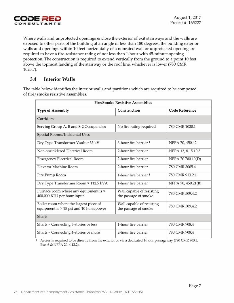
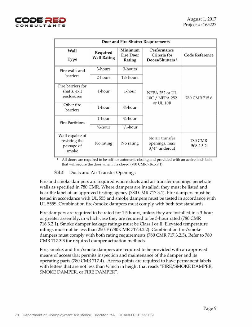
FIRE PROTECTION1. All new work to meet code and be coordinated with local Fire Marshall.2. Fire protection service to enter building at basement level.3. Fire pump room currently accommodated at basement level, may not be necessary.
HVAC1. All new HVAC work to meet code.2. Primary units, distribution, terminal units, and controls to be optimized for projected program.3. Basement and Roof level to house mechanical equipment with chases in between.
ELECTRICAL1. All new electrical work to meet code.2. All new power service and distribution, all new LED lighting. 3. Fire alarm, Telecom, Security, and AV all new and designed to accommodate projected program.4. Electrical service to enter building at ground floor, mirrored by utility owned vault under sidewalk.

FEASIBILITY STUDY REPORT 2017.09.07 Jones Architecture 69
70 Department of Unemployment Assistance, Brockton MA. DCAMM DCP1722 HS1
H. SYSTEMS NARRATIVES
CODE ANALYSIS
FEASIBILITY STUDY REPORT 2017.09.07 Jones Architecture 71
72 Department of Unemployment Assistance, Brockton MA. DCAMM DCP1722 HS1
FEASIBILITY STUDY REPORT 2017.09.07 Jones Architecture 73
74 Department of Unemployment Assistance, Brockton MA. DCAMM DCP1722 HS1
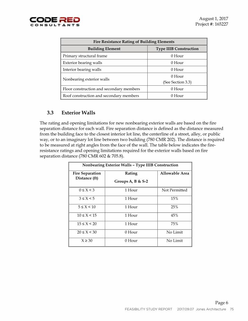
FEASIBILITY STUDY REPORT 2017.09.07 Jones Architecture 75
76 Department of Unemployment Assistance, Brockton MA. DCAMM DCP1722 HS1
FEASIBILITY STUDY REPORT 2017.09.07 Jones Architecture 77
••
•
78 Department of Unemployment Assistance, Brockton MA. DCAMM DCP1722 HS1
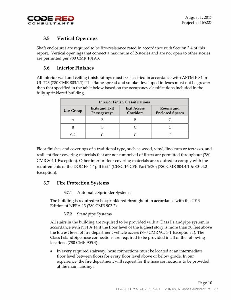
FEASIBILITY STUDY REPORT 2017.09.07 Jones Architecture 79
•

80 Department of Unemployment Assistance, Brockton MA. DCAMM DCP1722 HS1
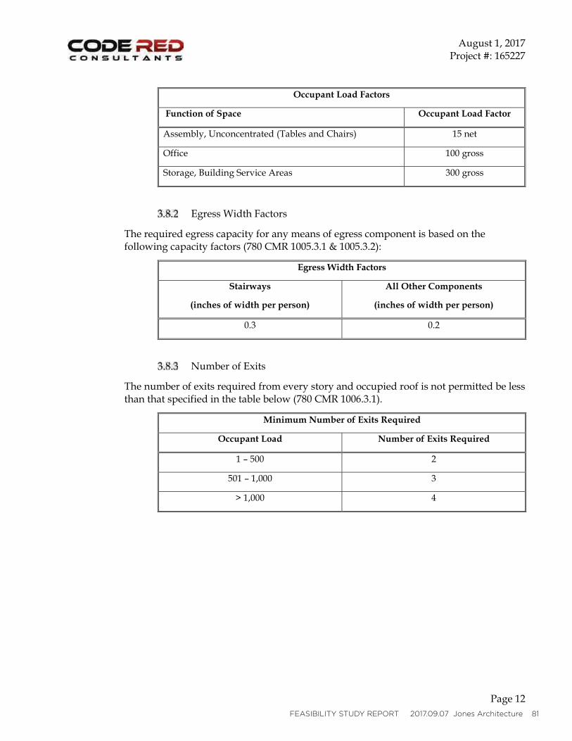
•
•
•
•••
•
FEASIBILITY STUDY REPORT 2017.09.07 Jones Architecture 81

82 Department of Unemployment Assistance, Brockton MA. DCAMM DCP1722 HS1
FEASIBILITY STUDY REPORT 2017.09.07 Jones Architecture 83
84 Department of Unemployment Assistance, Brockton MA. DCAMM DCP1722 HS1
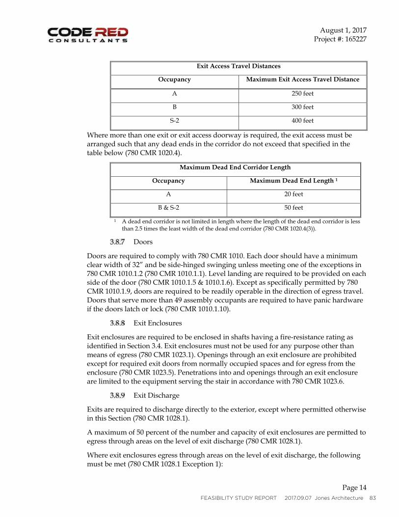
•
•
•
••
•
••
••
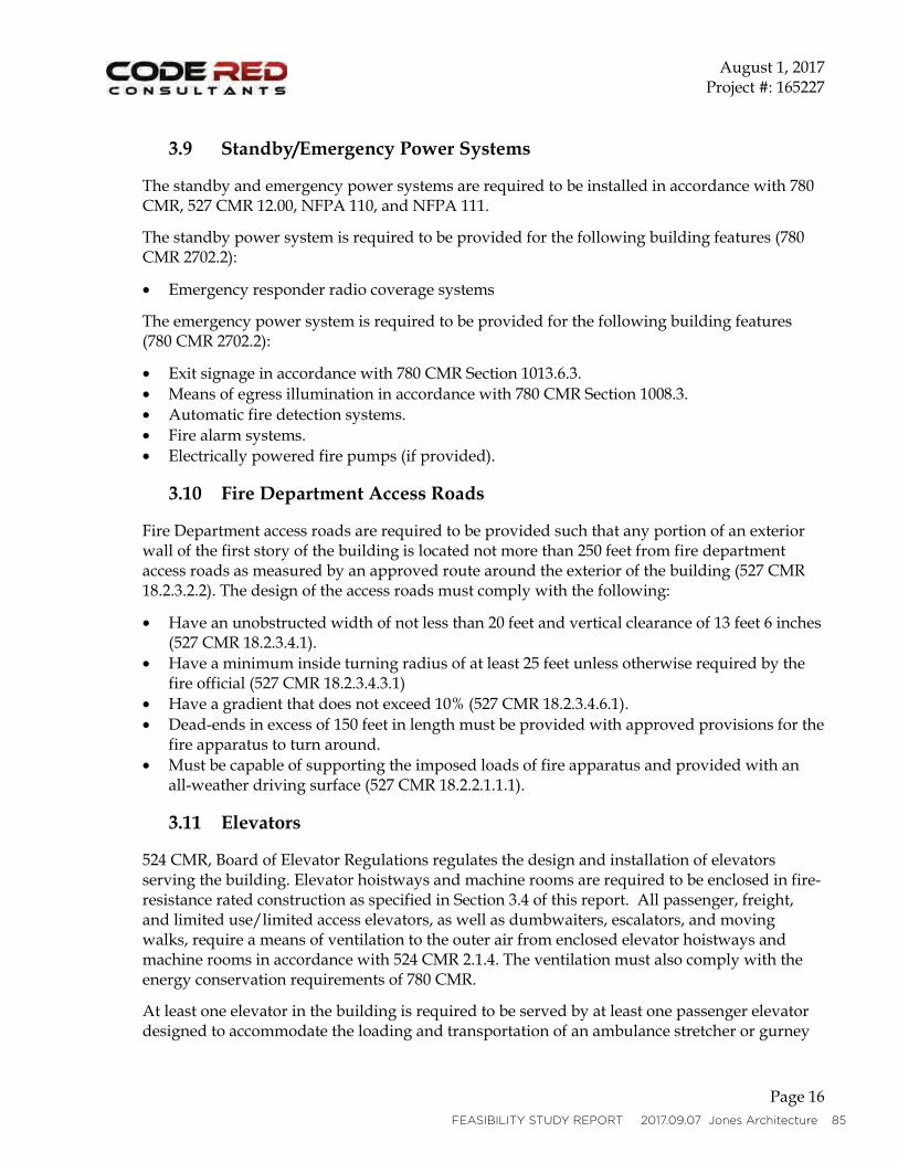
FEASIBILITY STUDY REPORT 2017.09.07 Jones Architecture 85
•
•••••
•
•
••
•
86 Department of Unemployment Assistance, Brockton MA. DCAMM DCP1722 HS1

FEASIBILITY STUDY REPORT 2017.09.07 Jones Architecture 87
88 Department of Unemployment Assistance, Brockton MA. DCAMM DCP1722 HS1
H. SYSTEMS NARRATIVES
STRUCTURAL
FEASIBILITY STUDY REPORT 2017.09.07 Jones Architecture 89
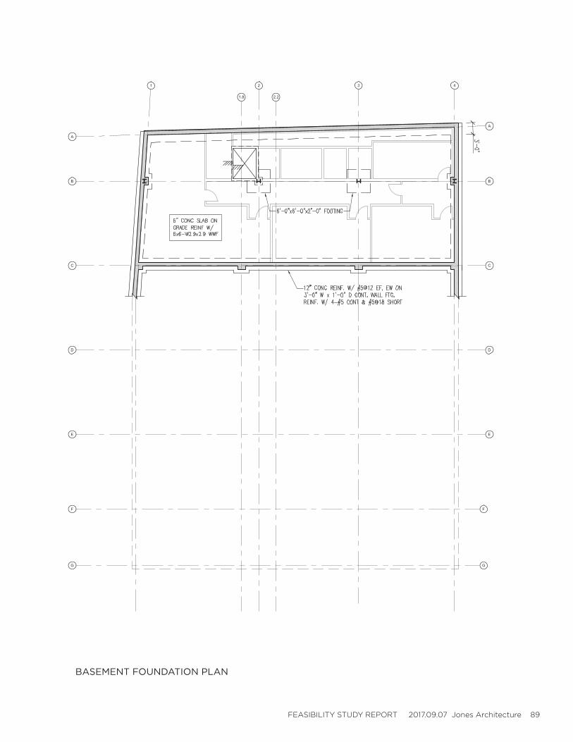
BASEMENT FOUNDATION PLAN
90 Department of Unemployment Assistance, Brockton MA. DCAMM DCP1722 HS1
FIRST FLOOR FRAMING PLAN
FEASIBILITY STUDY REPORT 2017.09.07 Jones Architecture 91
SECOND FLOOR FRAMING PLAN
92 Department of Unemployment Assistance, Brockton MA. DCAMM DCP1722 HS1
THIRD FLOOR FRAMING PLAN
FEASIBILITY STUDY REPORT 2017.09.07 Jones Architecture 93
LOW ROOF FRAMING PLAN
94 Department of Unemployment Assistance, Brockton MA. DCAMM DCP1722 HS1
HIGH ROOF FRAMING PLAN

FEASIBILITY STUDY REPORT 2017.09.07 Jones Architecture 95

96 Department of Unemployment Assistance, Brockton MA. DCAMM DCP1722 HS1
H. SYSTEMS NARRATIVES
PLUMBING
FEASIBILITY STUDY REPORT 2017.09.07 Jones Architecture 97
•••••••
98 Department of Unemployment Assistance, Brockton MA. DCAMM DCP1722 HS1
FEASIBILITY STUDY REPORT 2017.09.07 Jones Architecture 99

100 Department of Unemployment Assistance, Brockton MA. DCAMM DCP1722 HS1

FEASIBILITY STUDY REPORT 2017.09.07 Jones Architecture 101
102 Department of Unemployment Assistance, Brockton MA. DCAMM DCP1722 HS1
H. SYSTEMS NARRATIVES
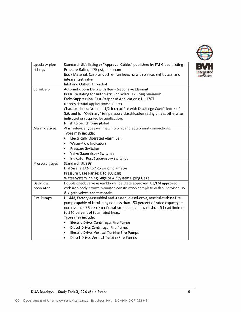
FIRE PROTECTION
FEASIBILITY STUDY REPORT 2017.09.07 Jones Architecture 103
•o
•ooooo
•oo
•ooooo
•oo
•o
•
104 Department of Unemployment Assistance, Brockton MA. DCAMM DCP1722 HS1
•
••••
•
FEASIBILITY STUDY REPORT 2017.09.07 Jones Architecture 105
•••••••••
106 Department of Unemployment Assistance, Brockton MA. DCAMM DCP1722 HS1
•••••
••••

FEASIBILITY STUDY REPORT 2017.09.07 Jones Architecture 107
108 Department of Unemployment Assistance, Brockton MA. DCAMM DCP1722 HS1
H. SYSTEMS NARRATIVES
MECHANICAL
FEASIBILITY STUDY REPORT 2017.09.07 Jones Architecture 109
110 Department of Unemployment Assistance, Brockton MA. DCAMM DCP1722 HS1
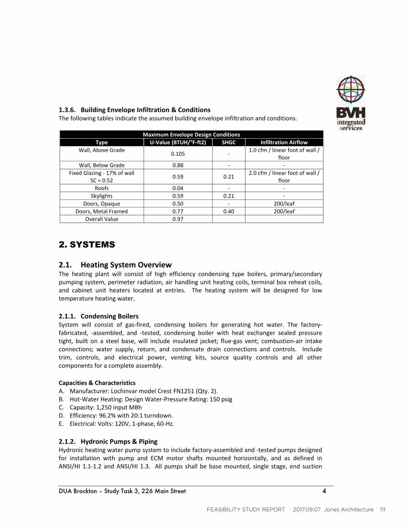
FEASIBILITY STUDY REPORT 2017.09.07 Jones Architecture 111
112 Department of Unemployment Assistance, Brockton MA. DCAMM DCP1722 HS1
FEASIBILITY STUDY REPORT 2017.09.07 Jones Architecture 113
114 Department of Unemployment Assistance, Brockton MA. DCAMM DCP1722 HS1
FEASIBILITY STUDY REPORT 2017.09.07 Jones Architecture 115

116 Department of Unemployment Assistance, Brockton MA. DCAMM DCP1722 HS1
FEASIBILITY STUDY REPORT 2017.09.07 Jones Architecture 117
118 Department of Unemployment Assistance, Brockton MA. DCAMM DCP1722 HS1
FEASIBILITY STUDY REPORT 2017.09.07 Jones Architecture 119
120 Department of Unemployment Assistance, Brockton MA. DCAMM DCP1722 HS1
FEASIBILITY STUDY REPORT 2017.09.07 Jones Architecture 121
122 Department of Unemployment Assistance, Brockton MA. DCAMM DCP1722 HS1
H. SYSTEMS NARRATIVES
ELECTRICAL, AV, COMMUNICATIONS, SECURITY
38 Front Street, 3FL, Worcester, MA 01608 Office: 508.797.0333
DUA Brockton – Study Task 3, 226 Main Street 1
August 6, 2017
D50 ELECTRICAL
D5010 ELECTRICAL SERVICE AND DISTRIBUTION – Base Design
A. The electrical system shall be designed per NFPA 70, the Massachusetts Electrical Code (MEC), Federal, State, local and all other applicable codes.
B. Number of services: Single utility service is required.
C. The Electrical Design will meet or exceed LEED Silver, v4 standards for energy efficiency.
A. Main Switchboard:
1. Service entrance equipment shall comply with NEMA PB 2, NFPA 70 and UL 891. 2. Nominal System Voltage: 480Y/277V. 3. Main-Bus: 800A. 4. Main Breaker: 800A, 65KAIC with Ground Fault Protection. 5. Phase and Neutral Buses and Connections: Three phase, four wire unless otherwise
indicated. Tin-plated, high-strength, electrical-grade aluminum alloy with tin-plated aluminum circuit-breaker line connections.
6. Ground Bus: 1/4-by-2-inch- (6-by-50-mm-) minimum size, hard-drawn copper of 98 percent conductivity, equipped with pressure connectors for feeder and branch-circuit ground conductors.
7. Surge Protection Device Description: IEEE C62.41-compliant, integrally mounted, solid-state, parallel-connected, with sine-wave tracking suppression and filtering modules, UL 1449, second edition, short-circuit current rating matching or exceeding the switchboard short-circuit rating.
8. All circuit breakers in the main switchboard shall be Standard Micrologic (LSI) with solid-state trip unit and flux transfer shunt trip. Breakers shall have trip rating plugs with ratings as indicated on the drawings. Rating plugs shall be interlocked so they are NOT interchangeable between frames and interlocked such that a breaker cannot be latched with the rating plug removed.
9. Secondary feeders will be 8 sets of 4-600 kCMIL in 8-4” PVC Schedule 40 conduits. D5020 INTERIOR DISTRIBUTION TRANSFORMERS – Base Design
A. The interior distribution transformer shall be DOE 2016 compliant, ST20 and relevant NEMA, UL and IEEE standards; 200% rated neutral; 60Hz rated. All terminals, including those for changing taps, must be readily accessible by removing a front cover plate. Windings shall be continuous with terminations brazed or welded. 10kV BIL.
FEASIBILITY STUDY REPORT 2017.09.07 Jones Architecture 123
2 DUA Brockton – Study Task 3, 226 Main Street
A. Insulation System: Shall be NOMEX-based with an Epoxy Co-polymer impregnant for lowest environmental impact, long term reliability and long life expectancy.
1. Class: 220 degrees C. 2. Impregnant Properties for low emissions during manufacturing, highest reliability and life
expectancy. 3. Epoxy co-polymer. 4. VOC: less than 1.65 lbs. /gal (low emissions during manufacturing). 5. Water absorption (24hrs @25C): less than 0.05% (superior insulation, longer life).6. Chemical Resistance: Must have documented excellent performance rating by supplier. 7. Dielectric Strength: minimum of 3200 volts/mil dry (for superior stress, overvoltage
tolerance). 8. Dissipation Factor: max. 0.02 @25C to reduce aging of insulation, extending useful life. 9. Operating Temperature Rise: 130 degree C in a 40 degree C maximum ambient. 10. Noise levels: Per NEMA ST-20.
D5030 PANELBOARDS – Base Design
A. Panelboards shall comply with UL 67, UL 50 and NEMA PB 1.
B. Panelboards for non-linear loads shall be UL listed, including heat rise tested, in accordance with UL 67, except with the neutral assembly installed and carrying 200 percent of the phase bus current during testing. Provide molded case circuit breakers in accordance with UL 489.
C. Surge Protection Device for non-linear panelboards: IEEE C62.41.1 – 2002, IEEE C62.41.2 –2002, UL 1449 Third Edition, or most recent edition & NEC Article 285 -compliant and test devices according to IEEE C62.45 - 2002, integrally mounted, bolt-on, solid-state, parallel-connected, modular (with field-replaceable modules) type, with sine-wave tracking suppression and filtering modules, UL labeled with 200 kA short-circuit current rating (SCCR), and matching or exceeding the panelboard short-circuit rating, redundant suppression circuits, with thermally protected metal-oxide visitors.
D5040 ENCLOSED SWITCHES AND CIRCUIT BREAKERS – Base Design
A. Circuit Breakers: Provide molded case circuit breakers in accordance with UL 489. Provide with solid neutral when grounded conductor is present.
B. Fusible Switch, 800A and Smaller: NEMA KS 1, Type HD, with clips or bolt pads to accommodate specified fuses, lockable handle with capability to accept two padlocks, and interlocked with cover in closed position.
C. Non-fusible Switch, 800 A and Smaller: NEMA KS 1, Type HD, lockable handle with capability to accept two padlocks, and interlocked with cover in closed position.
D5050 GENERAL PURPOSE ELECTRICAL POWER – Base Design
A. A minimum of three general purpose duplex receptacles and one computer double duplex receptacle shall be provided in office and cubical spaces.

124 Department of Unemployment Assistance, Brockton MA. DCAMM DCP1722 HS1
3 DUA Brockton – Study Task 3, 226 Main Street
B. A minimum of one general purpose duplex receptacle shall be provided in utility and storage rooms.
C. Multiple service floor outlets or fire rated poke-thru devices shall be provided for equipment and appliances in the commons areas when the equipment is to be placed on worktables, counters, systems furniture, or cabinets that are not against fixed walls.
D. All new feeders shall be installed in PVC conduits when installed underground or under slab; or in EMT when installed concealed or exposed inside the building. All new branch circuit wiring shall be Type MC cable. All telecommunications and low voltage wiring shall be installed in conduit stubs to accessible ceilings, ladder tray, wire basket and supported by j-hooks.
D5060 LIGHTING – Base Design
A. Interior Lighting System
1. A high efficiency lighting system shall be provided in all interior spaces as well as on the exterior of the building. The design aim is to deliver a lighting system with a light power density not exceeding 0.7W/sq. ft. Linear direct/indirect fixtures shall be LED; recessedfixtures shall be LED; exterior light fixtures shall be LED.
2. Interior lighting shall be controlled with an automatic control device to shut off building lighting in all spaces. This automatic control device shall function on either on a scheduled basis using a time of day operated control device that turns lighting off at specific programmed times; or an occupant sensor that shall turn lighting off within 30 minutes of an occupant leaving a space; or an unscheduled basis by occupant intervention.
3. Each space enclosed by ceiling-height partitions shall have at least one control device to independently control the general lighting within the space. Each control device shall be activated either manually by an occupant or automatically by sensing an occupant.
4. Each perimeter office space enclosed by ceiling-height partitions shall have a manual control to allow the occupant to uniformly reduce the connected lighting load by at least 50% or shall be provided with automatic daylighting controls.
B. Light Fixtures
1. All light fixtures shall be LED type. 2. LED modules shall include the following features unless otherwise indicated: 3. Comply with IES LM-79 and LM-80 requirements. 4. Minimum CRI 85 and color temperature 3000° K unless otherwise specified in LIGHTING
FIXTURE SCHEDULE.5. Minimum Rated Life: 50,000 hours per IES L70. 6. Light output lumens as indicated in the LIGHTING FIXTURE SCHEDULE. 7. LED drivers shall include the following features unless otherwise indicated: 8. Minimum efficiency: 85% at full load. 9. Minimum Operating Ambient Temperature: -20° C. (-4° F.) 10. Input Voltage: 120 - 277V (±10%) at 60 Hz. 11. Integral short circuit, open circuit, and overload protection. 12.13.14. Comply with FCC 47 CFR Part 15.
FEASIBILITY STUDY REPORT 2017.09.07 Jones Architecture 125
4 DUA Brockton – Study Task 3, 226 Main Street
15. Installation shall meet requirements of manufacturer's recommendations and the additional requirements for "Severe Seismic Disturbance" contained in ASTM E 580. Fixture support wires shall conform to ASTM A 641/A 641M, galvanized regular coating, soft temper.
16. All exterior lighting to have lightning protection and grounding. D5070 LIGHTING CONTROLS – Base Design
A. The lighting control system shall utilize the Digital Addressable Lighting Interface (DALI) protocol to transmit data to and from Input Devices and End Devices.
B. Input Devices: occupancy sensors, daylight sensors, multi sensors (combined daylight, occupancy and temperature), wall mount switches and dimmers.
C. End Devices: DALI LED drivers, DALI field addressable relays, DALI relay panels, DALI dimming modules.
D. Control Equipment: lighting control panels, touch screens, server with database and end-user application(s).
E. All building light fixtures shall be controlled by the lighting control system. D5080 WIRING – Base Design
A. Provide wiring and connections for special outlets where required. All homerun circuits must contain no more than 3 phase conductors.
1. Conductors: Copper. Comply with NEMA WC 70. 2. Conductor Insulation: 90 degree rated; Comply with NEMA WC 70 for THHN, THWN-
2 and XHHW-2. 3. Multi-conductor Cable: Comply with NEMA WC 70 for metal-clad cable, Type MC with
ground wire. 4. Emergency System Feeders: Emergency System Feeders: Mineral-insulated, metal-
sheathed cable, Type MI.5. Conductor insulation and multi-conductor cable applications and wiring methods 6. Service Entrance: Type XHHW-2, single conductors in raceway. 7. Exposed Feeders: Type THHN-THWN-2, single conductors in raceway. 8. Emergency System Feeders: Mineral-insulated, metal-sheathed cable, Type MI. 9. Feeders Concealed in Ceilings, Walls, Partitions, and Crawlspaces: Type THHN-THWN-
2, single conductors in raceway; Metal-clad cable, Type MC. 10. Feeders Concealed in Concrete, below Slabs-on-Grade, and underground: Type THHN-
THWN-2, single conductors in raceway. 11. Exposed Branch Circuits, Including in Crawlspaces: Type THHN-THWN-2, single
conductors in raceway; Metal-clad cable, Type MC.12. Branch Circuits Concealed in Ceilings, Walls, and Partitions: Type THHN-THWN-2,
single conductors in raceway; Metal-clad cable, Type MC. 13. Branch Circuits Concealed in Concrete, below Slabs-on-Grade, and Underground: Type
THHN-THWN-2, single conductors in raceway. 14. Cord Drops and Portable Appliance Connections: Type SO, hard service cord with
stainless-steel, wire-mesh, and strain relief device at terminations to suit application. 15. Class 1 Control Circuits: Type THHN-THWN-2, in raceway.
126 Department of Unemployment Assistance, Brockton MA. DCAMM DCP1722 HS1
5 DUA Brockton – Study Task 3, 226 Main Street
16. Class 2 Control Circuits: Type THHN-THWN-2, in raceway; Metal-clad cable, Type MC. D5090 EMERGENCY/STANDBY POWER SYSTEM – Base Design
A. An 30kVA / 27kW Inverter Power Systems shall work with any type of lighting load to provide full light output for minimum 90-min. It shall be designed to support incandescent, fluorescent, HID*, quartz re-strike or halogen lamps. It will work into these loads at cold starts for all normally off circuits or normally on circuits.
B. UL listed to UL924. System to meet NFPA101, NFPA70, NFPA 110, OSHA, UBC, SBCCI standards.
C. The equipment as well as the feeders shall be in 2-hour rated emergency electric room/closet. The life safety branch shall power egress and exit lighting, communications systems and the fire alarm system.
1. The Inverter System will feed the following loads:
a. Emergency life safety:
1) Egress and exit lighting.
2) Fire alarm system.
3) Emergency communications systems.
4) Electrified egress doors. D5090 STANDBY POWER SYSTEM – Base Design
A. An 30kVA / 24kW Uninterruptable Power Supply (UPS). It shall be designed to support data system backup and safe power down during loss of power.
B. The equipment as well as the feeders shall be in 1-hour rated electric room/closet.
1. The UPS will feed the following loads:
a. Telecommunications System:
1) Telecommunications EF, TER and TR rooms D5090 EMERGENCY/STANDBY POWER SYSTEM – Add Alt
A. The emergency/standby generator shall be 125kW/154kVA, 277Y/480V, 3-Phase, 4-Wire diesel generator with factory sound attenuated enclosure. The generator shall have a base-mounted integral fuel oil tank sized for 48-hours of back up.
B. A 200A automatic transfer switch shall be installed for the emergency life safety branch; a 400A automatic transfer switch shall be provided for optional standby branch.
C. The generator shall feed the life safety branch with a 100A-3P circuit breaker and the optional standby branch with a 200A-3P circuit breaker.
FEASIBILITY STUDY REPORT 2017.09.07 Jones Architecture 127
6 DUA Brockton – Study Task 3, 226 Main Street
D. The life safety transfer and distribution equipment as well as the feeders shall be located in 2-hour rated emergency electric room/closet. The life safety branch shall power egress and exit lighting, communications systems and the fire alarm system.
E. The optional standby transfer, distribution equipment and feeders shall be located in the main electric room. The standby branch shall provide back power for boilers and associated pumps, server room and telecommunications closets, selected kitchen loads and heating loads in the Common spaces.
1. The generator will be located on the exterior of the building.
2. The generator will feed the following loads:
a. Emergency life safety:
1) Egress and exit lighting.
2) Fire alarm system.
3) Emergency communications systems.
4) Generator light, receptacle, heater and battery charger.
5) Electrified egress doors.
b. Emergency standby:
1) Stair and elevator shaft pressurization fans and associated control equipment.
2) Elevator; one elevator designated for emergency use.
c. Optional standby:
1) Telecommunications EF, TER and TR rooms and associated dedicated HVAC units.
2) Security rooms and security systems.
3) Boilers and associated pumps.
4) Elevators; one elevator will operate at any given time.
d. Fire pump D5100 SITE ELECTRICAL GENERATION – Add Alt
A. Option 1: Provide 60kW Roof-Mounted Photovoltaic System. D5110 GROUNDING SYSTEM – Base Design
A. Comply with UL 467.
B. Grounding Conductors: Route along shortest and straightest paths possible, unless otherwise indicated or required by Code. Avoid obstructing access or placing conductors where they may be subjected to strain, impact, or damage.
128 Department of Unemployment Assistance, Brockton MA. DCAMM DCP1722 HS1
7 DUA Brockton – Study Task 3, 226 Main Street
C. Ground Rods: Drive rods until tops are 2 inches (50 mm) below finished floor or final grade, unless otherwise indicated.
D. Interconnect ground rods with grounding electrode conductor below grade and as otherwise indicated. Make connections without exposing steel or damaging coating, if any.
E. For grounding electrode system, install at least three rods spaced at least one-rod length from each other and located at least the same distance from other grounding electrodes, and connect to the service grounding electrode conductor.
F. Bonding Straps and Jumpers: Install in locations accessible for inspection and maintenance, except where routed through short lengths of conduit.
G. Bonding to Structure: Bond straps directly to basic structure, taking care not to penetrate any adjacent parts.
H. Bonding to Equipment Mounted on Vibration Isolation Hangers and Supports: Install so vibration is not transmitted to rigidly mounted equipment.
I. Use exothermic-welded connectors for outdoor locations, but if a disconnect-type connection is required, use a bolted clamp.
J. Grounding and Bonding for Piping:
1. Metal Water Service Pipe: Install insulated copper grounding conductors, in conduit, from building's main service equipment, or grounding bus, to main metal water service entrances to building. Connect grounding conductors to main metal water service pipes, using a bolted clamp connector or by bolting a lug-type connector to a pipe flange, using one of the lug bolts of the flange. Where a dielectric main water fitting is installed, connect grounding conductor on street side of fitting. Bond metal grounding conductor conduit or sleeve to conductor at each end.
2. Sprinkler Service Pipe: Install insulated copper grounding conductors, in conduit, from building's main service equipment, or grounding bus, to main sprinkler service entrances to building. Connect grounding conductors to sprinkler service pipes, using a bolted clamp connector or by bolting a lug-type connector to a pipe flange, using one of the lug bolts of the flange. Where a dielectric main water fitting is installed, connect grounding conductor on street side of fitting. Bond metal grounding conductor conduit or sleeve to conductor at each end.
3. Use braided-type bonding jumpers to electrically bypass water meters. Connect to pipe with a bolted connector.
4. Bond each aboveground portion of gas piping system downstream from equipment shutoff valve.
K. Bonding Interior Metal Ducts: Bond metal air ducts to equipment grounding conductors of associated fans, blowers, electric heaters, and air cleaners. Install bonding jumper to bond across flexible duct connections to achieve continuity.
L. Grounding for Lightning Protection System: Install 3/0 AWG copper grounding conductor, in conduit, to the building's main service equipment.
FEASIBILITY STUDY REPORT 2017.09.07 Jones Architecture 129
8 DUA Brockton – Study Task 3, 226 Main Street
D5120 LIGHTNING PROTECTION SYSTEM - Optional
A. Comply with UL 96 and NFPA 780.
B. All components shall be aluminum and of the size, weight and construction to suit the applicationwhere used in accordance with requirements for Class I structures.
C. Roof conductors shall be aluminum, 24 strands 14-gauge, 98,600 circular mils, net weight 110 lbs. / 1000 ft.
D. Down conductors shall be copper, 29 strands 17-gauge, 65,600 circular mils, net weight 190 lbs. /1000ft.
E. i te in ls sh ll e solid ound lu inu ” ” ini u nd sh ll o ect 0 minimum above the object to be protected.
F. Air terminal bases shall be aluminum with bolt pressure cable connectors and shall be securely mounted with stainless steel screws or bolts.
G. Offset type bases shall be used at parapets and secured with stainless steel screws or anchors.
H. Adhesive type bases shall be secured with an adhesive compound which is compatible with the roofing system. The roofing manufacturer shall approve the adhesive compound.
I. Ground rods shall be 5/8" x 10'-0" minimum. They shall be connected to the system with a two-bolt copper clamp having a minimum length of 1-1/2" and employing stainless steel cap screws.
J. Cable fasteners shall be substantial in construction, galvanically compatible with the conductor and mounting surface.
K. Bonding devices, cable splicers and connectors shall be of aluminum with bolt pressure cable connectors.
L. Equipment on stacks and chimneys shall be protected from corrosion and sized in accordance with requirements.
M. Bolts, nuts and screws shall be stainless steel. D5130 POWER SYSTEM STUDIES – Base Design
A. Perform coordination study using approved computer software program. Prepare a written reportusing results of fault-current study. Comply with IEEE 399.
1. Calculate the maximum and minimum 1/2-cycle short-circuit currents.2. Calculate the maximum and minimum ground-fault currents. 3. Comply with IEEE 241 and IEEE 242 recommendations for fault currents and time
intervals. 4. Comply with IEEE 1584 for performing Arc Flash Hazard Calculations.
D60 COMMUNICATIONS
130 Department of Unemployment Assistance, Brockton MA. DCAMM DCP1722 HS1
9 DUA Brockton – Study Task 3, 226 Main Street
D6010 DATA COMMUNICATIONS – Base Design
A. The telecommunications cabling infrastructure shall be in compliance with the latest TIA standards. The utility company services shall be terminated in a telecommunications entrance facility (EF). Fire rated plywood backboards, grounding, equipment racks, 110-type punch down blocks, patch panels, conduit sleeves, and corridor cable tray system shall be provided in the EF, the telecommunications equipment room (TER) and the telecommunications rooms (TR). The pathway system, racks and equipment shall be sized for complete utilization of the service entrance cables and all voice and data outlets plus room for future growth. Voice and data outlets shall be provided in all administration areas and in the office spaces. Voice and data horizontal cabling shall be Category 6, unshielded, twisted pair, 8 conductor copper cable from each jack to the nearest telecommunications closet. Each end of each cable shall be labeled, the cables shall be terminated in accordance with TIA-568-B configuration, and tested in accordance with TIA standards.
B. A minimum of one voice/data outlet shall be provided in each office and office space. Two (2) data outlets shall be provided in the ceiling in corridors and assembly areas on 40 ft. centers for wireless access points. Media Center shall be provided with multiple data drops for workstations, printers, and access points.
C. Voice/data outlets shall be provided in multiple service floor outlets or fire rated poke-thru devices for equipment and appliances when the equipment is to be placed on worktables, counters, systems furniture, or cabinets that are not against fixed walls.
D. Backbone cables shall be provided between the EF, TER and each TR. Copper backbone cables shall be voice grade Category 3 cable. The cables shall be tested in accordance with ANSI/TIA standards. Optical fiber cables shall be 24-strand (50/125μm) multimode laser optimized cable. The cables shall be terminated in fiber optic patch panels at both ends. The circuits shall be tested for insertion loss at both ends at 1310 and 1550nm. High-resolution Optical Time Domain Reflectivity (OTDR) tests shall be performed on each fiber at one end.
E. The data communication equipment shall comprise of 10/100/1000 core and edge switches based on HP 5400 series chassis or equal. The switches shall be equipped with PoE and non-PoE 1-Gigabit copper Ethernet ports and 10-Gigabit fiber optic ports for connection between core and edge switches. The switches shall provide connection of a number of devices together (PCs, servers, printers, etc.) over a wired data system and control access to various parts of the network. The servers and storage farm shall be provided under the FF&E budget.
F. The Wi-Fi data communications equipment shall comprise of a controller and a/b/g/n access points based on Aruba or equal. The access points shall provide wireless connection of a number of devices together (PCs, servers, printers, etc.) over a Wi-Fi network and control access to various parts of the network.
D6020 VOICE COMMUNICATIONS – Base Design
A. Services from each telecommunications provider are required, preferably with delivery from different central offices or sites.
FEASIBILITY STUDY REPORT 2017.09.07 Jones Architecture 131
10 DUA Brockton – Study Task 3, 226 Main Street
B. The voice communications equipment shall comprise of a voice-over-IP (VoIP) telephone switching system, voicemail, distribution infrastructure, and telephone handsets. Telephone handsets shall be provided in each office space, in each administration office and common area.
C. The telephone system shall be integrated with the public address system so that the telephone handsets may be used for paging announcements.
D. Option 1: A cellular Distributed Antenna System (DAS) to extend the coverage range of cellular phone systems.
D6022 VERY SMALL APERTURE TERMINAL SATELLITE DATA TERMINAL – Optional
A. A Very Small Aperture Terminal (VSAT) data terminal acts as a backup data system and provides limited data capability if all ground based services were to fail. It provides a data capability that is not dependent on local service providers.
B. VSAT equipment shall be powered from UPS equipment that will provide a minimum of 20 minutes of service at full rated output.
D6025 PORTABLE RADIO SYSTEM – Optional
A. Provide a portable radio system. The portable radio system provides two-way radio communications for security services and facilities management services.
B. Fixed radio equipment shall be powered from UPS equipment that will provide a minimum of 20 minutes of service at full rated output.
D6030 AUDIO-VIDEO COMMUNICATIONS – Base Design
A. Local sound systems shall be installed in the media center. The sound system shall be integrated with the fire alarm system so that the system is muted when the fire alarm system is activated. The sound systems in each area shall incorporate wireless microphones, CD player and AM/FM tuner as well as two additional inputs.
B. Video projection systems consisting of a projector, motorized screen integrated with the sound system. The system shall incorporate DVD players, computers, incoming TV signals, and video production equipment; and remote control (Play, Stop, Pause, Rewind, Fast Forward, etc.) of central located equipment.
C. A digital signage system shall be installed at the main lobby and in the kitchen. The system shall be server based with multiple channels and capable of displaying different media content on a number of LCD TVs.
D6040 MEDIA DISTRIBUTION SYSTEM – Base Design
A. Provide a new media distribution system. The media distribution equipment shall comprise of an IPTV Video Distribution Head-end, a Digital Video-On-Demand Server and an MPEG-1 & 2 encoding/loading station. The system shall allow simultaneous streaming to TVs, Projectors, PCs, MACs via the LAN and WAN.
132 Department of Unemployment Assistance, Brockton MA. DCAMM DCP1722 HS1
11 DUA Brockton – Study Task 3, 226 Main Street
B. The system shall include encoders for local cable TV company (Cox Communications), and portable multicast Cart with camera and encoder system. The media distribution system shall be accessible over the s wired and wireless data communications system.
D6060 PUBLIC ADDRESS SYSTEM – Base Design
A. Provide public address (PA) systems in accordance with other DUA design manuals, design guides, and specifications.
D70 ELECTRONIC SAFETY AND SECURITY
D7010 UNIFIED SECURITY SYSTEM – Base Design
A. The Unified Security System shall comprise an access control system (ACS), intrusion detection system (IDS) and video surveillance system (VSS). The system shall be a Unified Security Platform and shall support the seamless unification of IP video management system (VMS) with access control system, intrusion detection system and video surveillance system under a single platform. The VMS user interface applications shall present a unified security interface for the management, configuration, monitoring, and reporting of embedded ACS, IDS, VSS and associated edge devices.
B. The IP video surveillance system shall comprise of cameras, encoders, decoders, network video recorders, data transmission wiring, control station with its associated equipment and software, recording control devices and all related local area network server and switches. Video surveillance network shall be on a dedicated LAN with limited connectivity to local network. The video surveillance system shall have the ability to be incorporated into the local network when infrastructure is implemented. The VMS shall present a true Unified Security Interface for live monitoring and reporting of the ACS, IDS and VSS. Advanced live video viewing and playback of archived video shall be available through the Surveillance UI.
C. The system and associated video edge devices shall be multicast enabled and approved for use in multicast environment. The Unified Security Platform shall have the ability to integrate with wireless and provide video configurations for low bandwidth connections. Upon an IDS alarm, the software shall have the capability to retrieve a predetermined associated live video or recorded video feed and display that video feed on a workstation monitor associated with the system. This shall occur automatically through software without operator input. The operator shall then have the capability to query the IDS events to view the associated recorded video of that location. The operator shall have the capability to export video to the hard drive or CD, or close the video window by acknowledging the alarm.
D. The ACS shall be hardwired for exterior doors and other designated doors. Card readers shall be installed at designated entry doors. Access to the building will be via key fobs. The IDS shall monitor all ground floor doors and windows. The VSS shall monitor all entry/exits, building perimeter and all corridors.
E. An intercom at the front door with the ability to release the front door from the administration office shall be provided.

FEASIBILITY STUDY REPORT 2017.09.07 Jones Architecture 133
12 DUA Brockton – Study Task 3, 226 Main Street
F. Door contacts shall be provided on all exterior doors and motions sensors/glass break detectors shall monitor the ground floor for intrusion alerts. Panic buttons shall be provided in the main office to directly call the Police Department in the event of emergencies.
G. Detection and Screening Systems: This system is not believed to be applicable to DUA. It is used only where specific site conditions require this level of security, detection and screening systems (DSS) include: X-ray screening machines, walk-through metal detectors (WTMD), hand-held metal detectors (HHMD), and desktop and hand-held trace/particle detectors (also called sniffers and itemizers).
D7020 FIRE ALARM SYSTEM – Base Design
A. The design of the fire alarm system shall be based on engineering criteria as defined by NFPA 72 and The Massachusetts State Building Code 780 CMR. The system shall be supported by standby batteries. The batteries shall support 24-hours of full supervisory operation followed by 15 minutes of alarm.
B. A combination audible-visual signaling appliances as required per NFPA 72 shall be provided. The audible-visual notification devices shall be located in all egress pathways, office spaces,public and common areas. Visual notification devices shall be provided in all offices. The devices shall be in compliance with the Americans with Disabilities Act (ADA).
C. Manual pull stations shall be located within 5 ft. of each means of egress and mounted at 44 in. above the floor to the activating lever of the box. The pull stations shall mechanically latch upon operation and remain so until manually reset by a key common to all system locks.
D. Photoelectric smoke detectors shall be located in egress pathways. Smoke detectors shall also be located at the top, bottom of each stairway; mechanical equipment; electrical; transformer; telephone equipment; elevator machine; or similar room. Sprinkler tamper and flow devices shall be wired for trouble and alarm indication respectively into the fire alarm control panel.
D7030 PUBLIC SAFETY RADIO DAS – Base Design
A. The building shall be both pre and post tested for fire and police department radio signal strength. At the request of this subcontractor, a test shall be scheduled with the Fire Department. This subcontractor shall employ the services of an integrator to perform the fire/police department radio signal strength. Any expense incurred by the test shall be the responsibility of this subcontractor.
B. The integrator shall have experience in the design and installation of Public Safety Systems and is expected to perform a site survey to determine the RF signal strength on or near the building grounds to determine the level of amplification necessary to provide clear and reliable radio communications over 95% of the overall area inside the building.
C. The radio test shall check the signal reception in several locations on the floor area. Signal strength shall be as required for clear reception throughout the building utilizing the type of hand held radio unit that is used by the Fire and Police Departments.
D. The DAS components include: Bi-Directional Amplifiers (BDA), Donor Antennas, Coverage Antennas, Coax Cable, Coax Connectors, Splitters, Combiners and Couplers.
134 Department of Unemployment Assistance, Brockton MA. DCAMM DCP1722 HS1
13 DUA Brockton – Study Task 3, 226 Main Street
E. Alarming: The BDA shall include the following outputs which shall interface to the fire alarm system. The integrator shall coordinate the installation of this alarm with the fire alarm contractor:Signal booster malfunction alarm, Loss of AC Power Alarm, Low Battery Alarm, Antenna Circuit Malfunction, and Charge Failure Alarm.
D7070 ELECTRONIC MONITORING AND CONTROL – Base Design
A. The electrical power monitoring meter shall calculate the electrical usage of electrical loads with the use of remote current transformers. The meter shall be microprocessor-based. The meter shall be capable of sampling each power waveform calculating power factor and harmonic content to achieve 0.5% accurate readings. The meter shall save the Kilowatt hour and Max demand readings, indefinitely, in non-volatile RAM during power outages, without the use of batteries until, at such time, the meter is re-energized.
B. The meter shall contain Modbus RS485 RTU communications as a st nd d e tu e. he ete s communication wires to be Daisy Chain, Parallel, and Star wired together then connected to a RS485 / RS232 converter, which then connects to the PC. Up to 255 meters shall be connected together, on a two wire buss, to be read by software in the PC. The software package shall allow the end-user to manually or automatically read the meters.
C. The software shall display power consumption data for each panel being monitored, total lighting load, computer power load, general purpose power load, elevator, HVAC load and total building load.
FEASIBILITY STUDY REPORT 2017.09.07 Jones Architecture 135
38 Front St. FL 3, Worcester, MA 01608 Office: 508.797.0333
August 6, 2017 Massachusetts Department of Unemployment (DUA) Brocton, Massachusetts RE: Schematic Design Room Narrative
Prepared by: Azim Rawji, P.E.
BUILDING ELECTRICAL SYSTEMS
1. Main Electrical Room
The Main Electrical Room is to be in the basement level and sized not less than 15’x20’ with a 1-hr fire rating. The Main Electrical Room shall house: Electric Switch Boards Main Distribution Boards Main Disconnects Main Electric Metering Main Service Transformers
2. Main Electrical Vault
The Main Electrical Room is to be feed by a Utility Co. supplied transformer. The Utility Co. will suggest the Vault location be located under the Main Street sidewalk. The Electrical Vault shall house: Main Electrical Service Transformer
3. Normal Distribution Closets – Floors 1 through 3
For efficient layout of electrical closets, we ask that Electrical Closets be designated on each floor and that they be stacked, and that their size be not less than 8’x10’. The Electrical Closets shall house: Floor Distribution Panels: Normal Power Panel Lighting Panel HVAC Panel Spare Floor Disconnects
Floor Electric Metering Floor Service Transformers
4. Emergency Distribution Closets – Basement – 3
For efficient layout of electrical closets, we ask that one Emergency Electrical Closets be designated on each floor, that they be stacked, and that their size be not less than 4’x8’.
136 Department of Unemployment Assistance, Brockton MA. DCAMM DCP1722 HS1
38 Front St. FL 3, Worcester, MA 01608 Office: 508.797.0333
i. The emergency life safety and legally required standby equipment will be installed in 2-hour rated rooms; the feeders for these branches will be installed in 2-hour rated shafts, rooms or the feeders themselves will be 2-hour rated assemblies.
The Emergency Electrical Closets shall house: Floor Distribution Panels: Emergency Power Panel Power and Lighting Panel HVAC Life Safety Panel – where applicable Fire Alarm Terminal Cabinets Life-Safety Inverter – Egress Lighting Floor Disconnects Floor Service Transformers
5. Main Telecom – Floor 1 Main Distribution Frame (MDF) Room: The existing MDF is located on level one of the building and houses the core switches and servers
For efficient layout of MDF rooms, we ask that the MDF be not less than 10’x20’ unless otherwise requested by IT Manager.
i. Design MDF systems with adequately sized room and infrastructure that shall comply with the BICSI standards.
a. Provide overhead cable management system and relocate rack power from wall receptacles to overhead receptacles to allow free access to front and rear of racks.
b. Provide power for cooling and humidity control systems within the space.
6. Telecom Closets – Basement, Floor 2 and 3
Intermediate Distribution Frame (IDF) Rooms: For efficient layout of IDF rooms, we ask that two IDFs be designated on each floor, that they be stacked, and that their size be not less than 8’x10’.
ii. Design IDF systems with adequately sized rooms and infrastructure that shall comply with the BICSI standards.
a. Provide overhead cable management system and relocate rack power from wall receptacles to overhead receptacles to allow free access to front and rear of racks.
b. Provide power for cooling and humidity control systems within the space.
7. Fire Alarm Room The Fire Alarm Panel could be integrated in the Main Electrical Closet but we recommend a dedicated 2-hr rated room serving Emergency Electrical to the Basement level. The Fire Alarm room shall contain, but not be limited to, the following and as required by 780 CMR:
The alarm system annunciation panel
FEASIBILITY STUDY REPORT 2017.09.07 Jones Architecture 137
38 Front St. FL 3, Worcester, MA 01608 Office: 508.797.0333
The Masterbox or central station transmitter Voice communication systems controls Fire pump status indicators “dedicated emergency telephone” Status indicators for all elevators Status indicators and controls for air handling systems and firefighter’s smoke control panel (FSCP). A graphic schematic of the FSCP approved by the design professional shall be submitted at time of permit application Controls for unlocking all stairway doors Sprinkler valve status and waterflow detector annunciating panels Emergency power, light and emergency system controls and status indicators Other requirements of 780 CMR, Section 911 In-building radio equipment as directed by the Fire Department Life-Safety Inverter – Egress Lighting, Fire Alarm, DAS System
8. Rooftop Controls Room – Penthouse
The Penthouse electrical panels shall share wall space with rooftop mechanical controls: Normal Power Panel Lighting Panel HVAC Panel Spare
138 Department of Unemployment Assistance, Brockton MA. DCAMM DCP1722 HS1
I. COST ESTIMATE

FEASIBILITY STUDY REPORT 2017.09.07 Jones Architecture 139
140 Department of Unemployment Assistance, Brockton MA. DCAMM DCP1722 HS1
I. COST ESTIMATE
35 HIGHLAND CIRCLE, NEEDHAM, MASSACHUSETTS
Architect: Jones Architecture
DCAMM DUA BROCKTON STUDY TASK 4
BROCKTON MA
PRE-SCHEMATIC
September 08, 2017
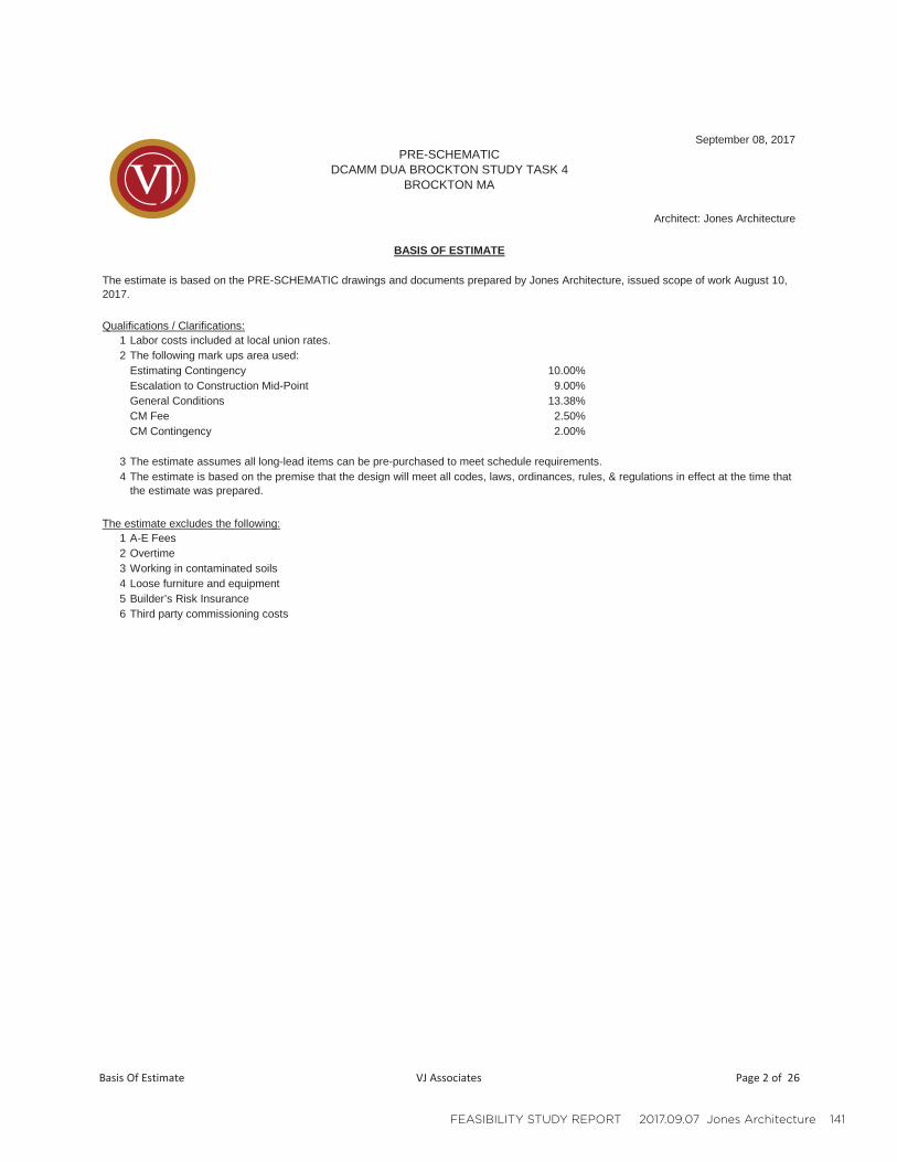
FEASIBILITY STUDY REPORT 2017.09.07 Jones Architecture 141
September 08, 2017
Qualifications / Clarifications:1 Labor costs included at local union rates.2 The following mark ups area used:
Estimating Contingency 10.00%Escalation to Construction Mid-Point 9.00%General Conditions 13.38%CM Fee 2.50%CM Contingency 2.00%
3 The estimate assumes all long-lead items can be pre-purchased to meet schedule requirements.4
The estimate excludes the following:1 A-E Fees2 Overtime3 Working in contaminated soils4 Loose furniture and equipment5 Builder’s Risk Insurance6 Third party commissioning costs
BASIS OF ESTIMATE
The estimate is based on the PRE-SCHEMATIC drawings and documents prepared by Jones Architecture, issued scope of work August 10, 2017.
PRE-SCHEMATICDCAMM DUA BROCKTON STUDY TASK 4
BROCKTON MA
Architect: Jones Architecture
The estimate is based on the premise that the design will meet all codes, laws, ordinances, rules, & regulations in effect at the time that the estimate was prepared.
Basis Of Estimate VJ Associates Page 2 of 26
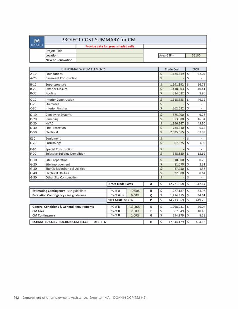
142 Department of Unemployment Assistance, Brockton MA. DCAMM DCP1722 HS1
Area GSF = 35100
Trade Cost $/SFA 10 1,124,519$ 32.04$A 20 $ $
B 10 1,991,392$ 56.73$B 20 1,418,303$ 40.41$B 30 314,582$ 8.96$
C 10 1,618,653$ 46.12$C 20 $ $C 30 262,682$ $
D 10 325,000$ 9.26$D 20 573,380$ 16.34$D 30 1,596,967$ 45.50$D 40 234,310$ 6.68$D 50 2,035,365$ 57.99$
E10 $ $E 20 67,575$ 1.93$
F 10 $ $F 20 548,320$ 15.62$
G 10 10,000$ 0.28$G 20 81,070$ 2.31$G 30 47,250$ 1.35$G 40 22,500$ 0.64$G 50 $ $
Direct Trade Costs A 12,271,868$ 342.14$
% of A 10.00% B 1,227,187$ 34.96$% of A+B 9.00% C 1,214,915$ 34.61$
Hard Costs A+B+C D 14,713,969$ 419.20$
General Conditions & General Requirements % of D 13.38% E 1,968,031$ 56.07$CM Fees % of D 2.50% F 367,849$ 10.48$CM Contingency % of D 2.00% G 294,279$ 8.38$
H 17,344,129$ 494.13$
Escalation Contingency see guidelines
ESTIMATED CONSTRUCTION COST (ECC) D+E+F+G
Site ImprovementSite Civil/Mechanical UtilitiesElectrical UtilitiesOther Site Construction
Estimating Contingency see guidelines
Site Preparation
PlumbingHVACFire ProtectionElectrical
EquipmentFurnishings
Special ConstructionSelective Building Demolition
Conveying Systems
New or Renovation
UNIFORMAT SYSTEM ELEMENTSFoundationsBasement Construction
SuperstructureExterior ClosureRoofing
Interior ConstructionStaircasesInterior Finishes
PROJECT COST SUMMARY for CMProvide data for green shaded cells
Project TitleLocation
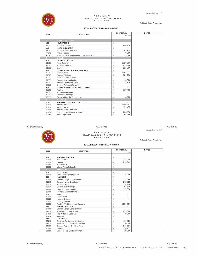
FEASIBILITY STUDY REPORT 2017.09.07 Jones Architecture 143
COST DETAIL NOTES35,100
A SUBSTRUCTUREA10 FOUNDATIONS -$ A1010 Standard Foundations 889,625$ A40 SLABS-ON-GRADE -$ A4010 Standard Slabs-on-Grade 101,838$ A4040 Pits and Bases 9,990$ A4090 Slab-On-Grade Supplementary Components 123,066$ B SHELLB10 SUPERSTRUCTURE -$ B1010 Floor Construction 1,328,596$ B1020 Roof Construction 435,796$ B1080 Stairs 227,000$ B20 EXTERIOR VERTICAL ENCLOSURES -$ B2010 Exterior Walls 1,004,073$ B2020 Exterior Windows 389,790$ B2030 Exterior Oversize Doors -$ B2050 Exterior Doors and Grilles 16,520$ B2070 Exterior Louvers and Vents 7,920$ B2080 Exterior Wall Appurtenances -$ B30 EXTERIOR HORIZONTAL ENCLOSURES -$ B3010 Roofing 310,402$ B3020 Roof Appurtenances -$ B3060 Horizontal Openings -$ B3080 Overhead Exterior Enclosures 4,180$ C INTERIORSC10 INTERIOR CONSTRUCTION -$ C1010 Interior Partitions 1,086,342$ C1030 Interior Doors 191,475$ C1040 Interior Grilles And Gates -$ C1070 Suspended Ceiling Construction 236,176$ C1090 Interior Specialties 104,660$
TOTAL PROJECT UNIFORMAT SUMMARY
CODE DESCRIPTION
September 08, 2017
Architect: Jones Architecture
PRE-SCHEMATICDCAMM DUA BROCKTON STUDY TASK 4
BROCKTON MA
UniFormat Summary VJ Associates Page 4 of 26
COST DETAIL NOTES35,100
TOTAL PROJECT UNIFORMAT SUMMARY
CODE DESCRIPTION
September 08, 2017
Architect: Jones Architecture
PRE-SCHEMATICDCAMM DUA BROCKTON STUDY TASK 4
BROCKTON MA
C30 INTERIOR FINISHES -$ C3010 Wall Finishes 47,040$ C3030 Flooring 215,642$ C3040 Stair Finishes -$ C3090 Interior Finish Schedules -$ D SERVICESD10 CONVEYING -$ D1010 Vertical Conveying Systems 325,000$ D20 PLUMBING -$ D2000 General Design Considerations 4,760$ D2010 Domestic Water Distribution 272,025$ D2020 Sanitary Waste 175,500$ D2030 Storm Water Drainage 103,545$ D2060 Other Plumbing Systems 17,550$ D2090 Plumbing System Materials -$ D30 HVAC -$ D3000 Design Basis -$ D3020 Heating Systems -$ D3030 Cooling Systems -$ D3050 Facility HVAC Distribution Systems 1,596,967$ D40 FIRE-PROTECTION -$ D4000 General Design Considerations -$ D4010 Wet-Pipe Sprinkler System 225,060$ D4030 Fire Protection Specialties 9,250$ D4040 Materials -$ D50 ELECTRICAL -$ D5010 Electrical Service and Distribution 410,826$ D5020 Electrical Generator Power System 120,000$ D5030 General Purpose Electrical Power 248,816$ D5040 Lighting 356,471$ D5080 Miscellaneous Electrical Systems 19,256$
UniFormat Summary VJ Associates Page 5 of 26
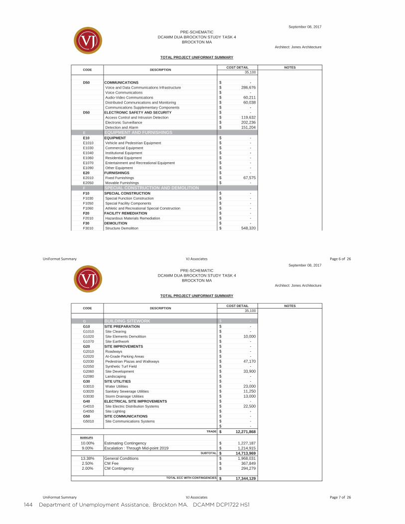
144 Department of Unemployment Assistance, Brockton MA. DCAMM DCP1722 HS1
COST DETAIL NOTES35,100
TOTAL PROJECT UNIFORMAT SUMMARY
CODE DESCRIPTION
September 08, 2017
Architect: Jones Architecture
PRE-SCHEMATICDCAMM DUA BROCKTON STUDY TASK 4
BROCKTON MA
D50 COMMUNICATIONS -$ Voice and Data Communications Infrastructure 286,676$ Voice Communications -$ Audio-Video Communications 60,211$ Distributed Communications and Monitoring 60,038$ Communications Supplementary Components -$
D50 ELECTRONIC SAFETY AND SECURITY -$ Access Control and Intrusion Detection 119,632$ Electronic Surveillance 202,236$ Detection and Alarm 151,204$
E EQUIPMENT AND FURNISHINGSE10 EQUIPMENT -$ E1010 Vehicle and Pedestrian Equipment -$ E1030 Commercial Equipment -$ E1040 Institutional Equipment -$ E1060 Residential Equipment -$ E1070 Entertainment and Recreational Equipment -$ E1090 Other Equipment -$ E20 FURNISHINGS -$ E2010 Fixed Furnishings 67,575$ E2050 Movable Furnishings -$ F SPECIAL CONSTRUCTION AND DEMOLITIONF10 SPECIAL CONSTRUCTION -$ F1030 Special Function Construction -$ F1050 Special Facility Components -$ F1060 Athletic and Recreational Special Construction -$ F20 FACILITY REMEDIATION -$ F2010 Hazardous Materials Remediation -$ F30 DEMOLITION -$ F3010 Structure Demolition 548,320$
UniFormat Summary VJ Associates Page 6 of 26
COST DETAIL NOTES35,100
TOTAL PROJECT UNIFORMAT SUMMARY
CODE DESCRIPTION
September 08, 2017
Architect: Jones Architecture
PRE-SCHEMATICDCAMM DUA BROCKTON STUDY TASK 4
BROCKTON MA
G BUILDING SITEWORK -$ G10 SITE PREPARATION -$ G1010 Site Clearing -$ G1020 Site Elements Demolition 10,000$ G1070 Site Earthwork -$ G20 SITE IMPROVEMENTS -$ G2010 Roadways -$ G2020 At-Grade Parking Areas -$ G2030 Pedestrian Plazas and Walkways 47,170$ G2050 Synthetic Turf Field -$ G2060 Site Development 33,900$ G2080 Landscaping -$ G30 SITE UTILITIES -$ G3010 Water Utilities 23,000$ G3020 Sanitary Sewerage Utilities 11,250$ G3030 Storm Drainage Utilities 13,000$ G40 ELECTRICAL SITE IMPROVEMENTS -$ G4010 Site Electric Distribution Systems 22,500$ G4050 Site Lighting -$ G50 SITE COMMUNICATIONS -$ G5010 Site Communications Systems -$
-$ 12,271,868$
MARKUPS
10.00% Estimating Contingency 1,227,187$ 9.00% Escalation : Through Mid-point 2019 1,214,915$
14,713,969$ 13.38% General Conditions 1,968,031$ 2.50% CM Fee 367,849$ 2.00% CM Contingency 294,279$
17,344,129$
TRADE
TOTAL ECC WITH CONTINGENCIES
SUBTOTAL
UniFormat Summary VJ Associates Page 7 of 26

FEASIBILITY STUDY REPORT 2017.09.07 Jones Architecture 145
LINE # I. II. III. IV. DESCRIPTION QTY UNIT RATE ASSEMBLY COST SUBTOTAL UNI III. SUBTOTAL UNI II.
A SUBSTRUCTUREA 10 FOUNDATIONSA 10 10 Standard FoundationsA 10 10 10 Wall Foundations
Footing, strip, 2'-0"W x 1'-0"D 240 LF 150.00 36,000$Footing, strip, 3'-0"W x 1'-0"D 236 LF 150.00 35,400$Foundation wall, 12"T x 4'-0"H 240 LF 250.00 60,000$Foundation wall, 12"T x 9'-0"H, basement 235 LF 465.00 109,275$Elevator pit wall 30 LF 400.00 12,000$Excavation & backfill for new footings 1 LS 90,000.00 90,000$Support of excavation, sheet piling @ Main St. & Rear Parking 1 LS 514,150.00 514,150$
A 10 10 30 Column FoundationsF1 - 6'-0" x 6'-0" x 2'-0" 8 EA 2,300.00 18,400$F2 - 4'-0" x 4'-0" x 2'-0" 12 EA 1,200.00 14,400$
A 10 10 90 Standard Foundation SupplementaryA1010 STANDARD FOUNDATIONS 889,625$
A10 FOUNDATIONS 889,625$ A 40 SLABS-ON-GRADEA 40 10 Standard Slabs-on-Grade
Slab on grade, 5" 9,258 SF 11.00 101,838$A4010 STANDARD SLABS-ON-GRADE 101,838$
A 40 40 Pits and BasesConcrete pad @ ACCU 1 83 SF 15.00 1,245$Concrete pad @ ACCU 2 87 SF 15.00 1,305$Concrete pad @ AHU 1 218 SF 15.00 3,270$Concrete pad @ AHU 2 224 SF 15.00 3,360$Elevator pit slab 54 SF 15.00 810$
A4040 PITS AND BASES 9,990$A 40 90 Slab-On-Grade Supplementary ComponentsA 40 90 10 Perimeter Insulation and Slab Insulation
Insulation for slab 9,312 SF 3.00 27,936$A 40 90 20 Vapor Retarder
Vapor retarder for slab 9,513 SF 2.00 19,026$A 40 90 30 Waterproofing
September 08, 2017PRE-SCHEMATIC
DCAMM DUA BROCKTON STUDY TASK 4BROCKTON MA
Architect: Jones Architecture
COST DETAIL
Building Detail VJ Associates Page 8 of 26
LINE # I. II. III. IV. DESCRIPTION QTY UNIT RATE ASSEMBLY COST SUBTOTAL UNI III. SUBTOTAL UNI II.
September 08, 2017PRE-SCHEMATIC
DCAMM DUA BROCKTON STUDY TASK 4BROCKTON MA
Architect: Jones Architecture
COST DETAIL
Waterproofing for slab 9,513 SF 8.00 76,104$A 40 90 40 Damp proofing
A4090 SLAB-ON-GRADE SUPPLEMENTARY COMPONENTS 123,066$A40 SLABS-ON-GRADE 234,894$
B SHELLB 10 SUPERSTRUCTUREB 10 10 Floor ConstructionB 10 10 10 Floor Structural Frame
Floor steel framing @ Level 01 80 TN 4,500.00 360,000$Floor steel framing @ Level 02 70 TN 4,500.00 315,000$Floor steel framing @ Level 03 w/ open to below 60 TN 5,500.00 330,000$Fireproofing spray for above 19,370 SF 2.00 38,740$
B 10 10 20 Floor Decks, Slabs, and ToppingsSlab on deck L01 2806 SF 10.00 28,060$Slab on deck L02 8851 SF 10.00 88,510$Slab on deck L03 7713 SF 10.00 77,130$Slab on deck L04 2542 SF 10.00 25,420$Metal deck L01 2806 SF 3.00 8,418$Metal deck L02 8851 SF 3.00 26,553$Metal deck L03 7713 SF 3.00 23,139$Metal deck L04 2542 SF 3.00 7,626$
B 10 10 50 RampsB 10 10 90 Floor Construction Supplementary Components
B1010 FLOOR CONSTRUCTION 1,328,596$B 10 20 Roof ConstructionB 10 20 10 Roof Structural Frame
Roof steel framing @ High Roof 30 TN 4,500.00 135,000$Roof steel framing @ Low Roof 40 TN 4,500.00 180,000$Fireproofing spray for above 9,233 SF 2.00 18,466$
B 10 20 20 Roof Decks, Slabs, and SheathingRoof slab, high roof 4026 SF 7.00 28,182$Roof slab, low roof 5207 SF 7.00 36,449$Roof deck, high roof 4,026 SF 3.00 12,078$Roof deck,low roof 5,207 SF 3.00 15,621$
Building Detail VJ Associates Page 9 of 26
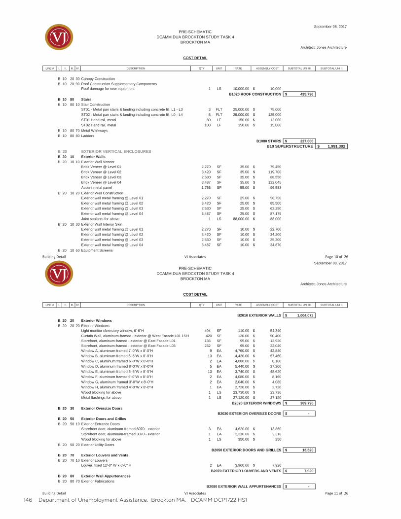
146 Department of Unemployment Assistance, Brockton MA. DCAMM DCP1722 HS1
LINE # I. II. III. IV. DESCRIPTION QTY UNIT RATE ASSEMBLY COST SUBTOTAL UNI III. SUBTOTAL UNI II.
September 08, 2017PRE-SCHEMATIC
DCAMM DUA BROCKTON STUDY TASK 4BROCKTON MA
Architect: Jones Architecture
COST DETAIL
B 10 20 30 Canopy ConstructionB 10 20 90 Roof Construction Supplementary Components
Roof dunnage for new equipment 1 LS 10,000.00 10,000$B1020 ROOF CONSTRUCTION 435,796$
B 10 80 StairsB 10 80 10 Stair Construction
ST01 - Metal pan stairs & landing including concrete fill, L1 - L3 3 FLT 25,000.00 75,000$ST02 - Metal pan stairs & landing including concrete fill, L0 - L4 5 FLT 25,000.00 125,000$ST01 Hand rail, metal 80 LF 150.00 12,000$ST02 Hand rail, metal 100 LF 150.00 15,000$
B 10 80 70 Metal WalkwaysB 10 80 80 Ladders
B1080 STAIRS 227,000$B10 SUPERSTRUCTURE 1,991,392$
B 20 EXTERIOR VERTICAL ENCLOSURESB 20 10 Exterior WallsB 20 10 10 Exterior Wall Veneer
Brick Veneer @ Level 01 2,270 SF 35.00 79,450$Brick Veneer @ Level 02 3,420 SF 35.00 119,700$Brick Veneer @ Level 03 2,530 SF 35.00 88,550$Brick Veneer @ Level 04 3,487 SF 35.00 122,045$Accent metal panel 1,756 SF 55.00 96,583$
B 20 10 20 Exterior Wall ConstructionExterior wall metal framing @ Level 01 2,270 SF 25.00 56,750$Exterior wall metal framing @ Level 02 3,420 SF 25.00 85,500$Exterior wall metal framing @ Level 03 2,530 SF 25.00 63,250$Exterior wall metal framing @ Level 04 3,487 SF 25.00 87,175$Joint sealants for above 1 LS 88,000.00 88,000$
B 20 10 30 Exterior Wall Interior SkinExterior wall metal framing @ Level 01 2,270 SF 10.00 22,700$Exterior wall metal framing @ Level 02 3,420 SF 10.00 34,200$Exterior wall metal framing @ Level 03 2,530 SF 10.00 25,300$Exterior wall metal framing @ Level 04 3,487 SF 10.00 34,870$
B 20 10 60 Equipment Screens
Building Detail VJ Associates Page 10 of 26
LINE # I. II. III. IV. DESCRIPTION QTY UNIT RATE ASSEMBLY COST SUBTOTAL UNI III. SUBTOTAL UNI II.
September 08, 2017PRE-SCHEMATIC
DCAMM DUA BROCKTON STUDY TASK 4BROCKTON MA
Architect: Jones Architecture
COST DETAIL
B2010 EXTERIOR WALLS 1,004,073$B 20 20 Exterior WindowsB 20 20 20 Exterior Windows
Light monitor clerestory window, 6'-6"H 494 SF 110.00 54,340$Curtain Wall, aluminum-framed - exterior @ West Facade L01 15'H 420 SF 120.00 50,400$Storefront, aluminum-framed - exterior @ East Facade L01 136 SF 95.00 12,920$Storefront, aluminum-framed - exterior @ East Facade L03 232 SF 95.00 22,040$Window A, aluminum framed 7'-0"W x 8'-0"H 9 EA 4,760.00 42,840$Window B, aluminum framed 6'-6"W x 8'-0"H 13 EA 4,420.00 57,460$Window C, aluminum framed 6'-0"W x 8'-0"H 2 EA 4,080.00 8,160$Window D, aluminum framed 8'-0"W x 8'-0"H 5 EA 5,440.00 27,200$Window E, aluminum framed 5'-6"W x 8'-0"H 13 EA 3,740.00 48,620$Window F, aluminum framed 6'-0"W x 8'-0"H 2 EA 4,080.00 8,160$Window G, aluminum framed 3'-0"W x 8'-0"H 2 EA 2,040.00 4,080$Window H, aluminum framed 4'-0"W x 8'-0"H 1 EA 2,720.00 2,720$Wood blocking for above 1 LS 23,730.00 23,730$Metal flashings for above 1 LS 27,120.00 27,120$
B2020 EXTERIOR WINDOWS 389,790$B 20 30 Exterior Oversize Doors
B2030 EXTERIOR OVERSIZE DOORS -$B 20 50 Exterior Doors and GrillesB 20 50 10 Exterior Entrance Doors
Storefront door, aluminum-framed 6070 - exterior 3 EA 4,620.00 13,860$Storefront door, aluminum-framed 3070 - exterior 1 EA 2,310.00 2,310$Wood blocking for above 1 LS 350.00 350$
B 20 50 20 Exterior Utility DoorsB2050 EXTERIOR DOORS AND GRILLES 16,520$
B 20 70 Exterior Louvers and VentsB 20 70 10 Exterior Louvers
Louver, fixed 12'-0" W x 6'-0" H 2 EA 3,960.00 7,920$B2070 EXTERIOR LOUVERS AND VENTS 7,920$
B 20 80 Exterior Wall AppurtenancesB 20 80 70 Exterior Fabrications
B2080 EXTERIOR WALL APPURTENANCES -$
Building Detail VJ Associates Page 11 of 26
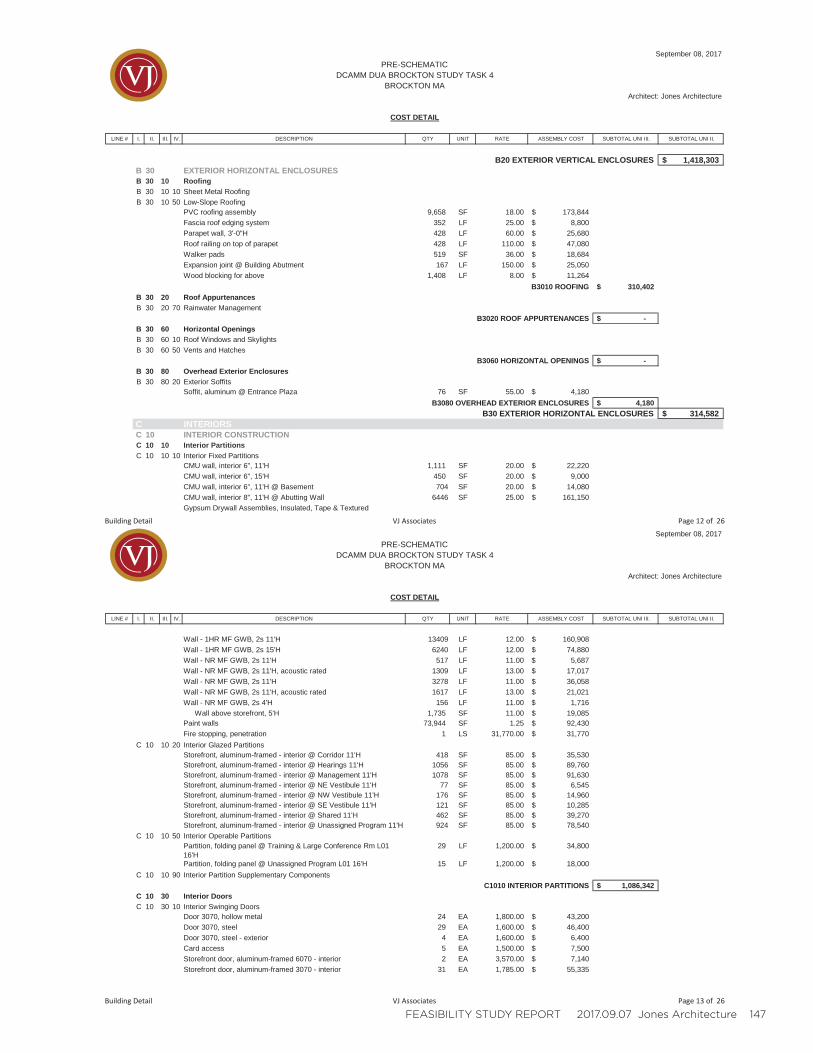
FEASIBILITY STUDY REPORT 2017.09.07 Jones Architecture 147
LINE # I. II. III. IV. DESCRIPTION QTY UNIT RATE ASSEMBLY COST SUBTOTAL UNI III. SUBTOTAL UNI II.
September 08, 2017PRE-SCHEMATIC
DCAMM DUA BROCKTON STUDY TASK 4BROCKTON MA
Architect: Jones Architecture
COST DETAIL
B20 EXTERIOR VERTICAL ENCLOSURES 1,418,303$ B 30 EXTERIOR HORIZONTAL ENCLOSURESB 30 10 RoofingB 30 10 10 Sheet Metal RoofingB 30 10 50 Low-Slope Roofing
PVC roofing assembly 9,658 SF 18.00 173,844$Fascia roof edging system 352 LF 25.00 8,800$Parapet wall, 3'-0"H 428 LF 60.00 25,680$Roof railing on top of parapet 428 LF 110.00 47,080$Walker pads 519 SF 36.00 18,684$Expansion joint @ Building Abutment 167 LF 150.00 25,050$Wood blocking for above 1,408 LF 8.00 11,264$
B3010 ROOFING 310,402$B 30 20 Roof AppurtenancesB 30 20 70 Rainwater Management
B3020 ROOF APPURTENANCES -$B 30 60 Horizontal OpeningsB 30 60 10 Roof Windows and SkylightsB 30 60 50 Vents and Hatches
B3060 HORIZONTAL OPENINGS -$B 30 80 Overhead Exterior EnclosuresB 30 80 20 Exterior Soffits
Soffit, aluminum @ Entrance Plaza 76 SF 55.00 4,180$B3080 OVERHEAD EXTERIOR ENCLOSURES 4,180$
B30 EXTERIOR HORIZONTAL ENCLOSURES 314,582$ C INTERIORSC 10 INTERIOR CONSTRUCTIONC 10 10 Interior PartitionsC 10 10 10 Interior Fixed Partitions
CMU wall, interior 6", 11'H 1,111 SF 20.00 22,220$CMU wall, interior 6", 15'H 450 SF 20.00 9,000$CMU wall, interior 6", 11'H @ Basement 704 SF 20.00 14,080$CMU wall, interior 8", 11'H @ Abutting Wall 6446 SF 25.00 161,150$Gypsum Drywall Assemblies, Insulated, Tape & Textured
Building Detail VJ Associates Page 12 of 26
LINE # I. II. III. IV. DESCRIPTION QTY UNIT RATE ASSEMBLY COST SUBTOTAL UNI III. SUBTOTAL UNI II.
September 08, 2017PRE-SCHEMATIC
DCAMM DUA BROCKTON STUDY TASK 4BROCKTON MA
Architect: Jones Architecture
COST DETAIL
Wall - 1HR MF GWB, 2s 11'H 13409 LF 12.00 160,908$Wall - 1HR MF GWB, 2s 15'H 6240 LF 12.00 74,880$Wall - NR MF GWB, 2s 11'H 517 LF 11.00 5,687$Wall - NR MF GWB, 2s 11'H, acoustic rated 1309 LF 13.00 17,017$Wall - NR MF GWB, 2s 11'H 3278 LF 11.00 36,058$Wall - NR MF GWB, 2s 11'H, acoustic rated 1617 LF 13.00 21,021$Wall - NR MF GWB, 2s 4'H 156 LF 11.00 1,716$
Wall above storefront, 5'H 1,735 SF 11.00 19,085$Paint walls 73,944 SF 1.25 92,430$Fire stopping, penetration 1 LS 31,770.00 31,770$
C 10 10 20 Interior Glazed PartitionsStorefront, aluminum-framed - interior @ Corridor 11'H 418 SF 85.00 35,530$Storefront, aluminum-framed - interior @ Hearings 11'H 1056 SF 85.00 89,760$Storefront, aluminum-framed - interior @ Management 11'H 1078 SF 85.00 91,630$Storefront, aluminum-framed - interior @ NE Vestibule 11'H 77 SF 85.00 6,545$Storefront, aluminum-framed - interior @ NW Vestibule 11'H 176 SF 85.00 14,960$Storefront, aluminum-framed - interior @ SE Vestibule 11'H 121 SF 85.00 10,285$Storefront, aluminum-framed - interior @ Shared 11'H 462 SF 85.00 39,270$Storefront, aluminum-framed - interior @ Unassigned Program 11'H 924 SF 85.00 78,540$
C 10 10 50 Interior Operable PartitionsPartition, folding panel @ Training & Large Conference Rm L01 16'H
29 LF 1,200.00 34,800$
Partition, folding panel @ Unassigned Program L01 16'H 15 LF 1,200.00 18,000$C 10 10 90 Interior Partition Supplementary Components
C1010 INTERIOR PARTITIONS 1,086,342$C 10 30 Interior DoorsC 10 30 10 Interior Swinging Doors
Door 3070, hollow metal 24 EA 1,800.00 43,200$Door 3070, steel 29 EA 1,600.00 46,400$Door 3070, steel - exterior 4 EA 1,600.00 6,400$Card access 5 EA 1,500.00 7,500$Storefront door, aluminum-framed 6070 - interior 2 EA 3,570.00 7,140$Storefront door, aluminum-framed 3070 - interior 31 EA 1,785.00 55,335$
Building Detail VJ Associates Page 13 of 26
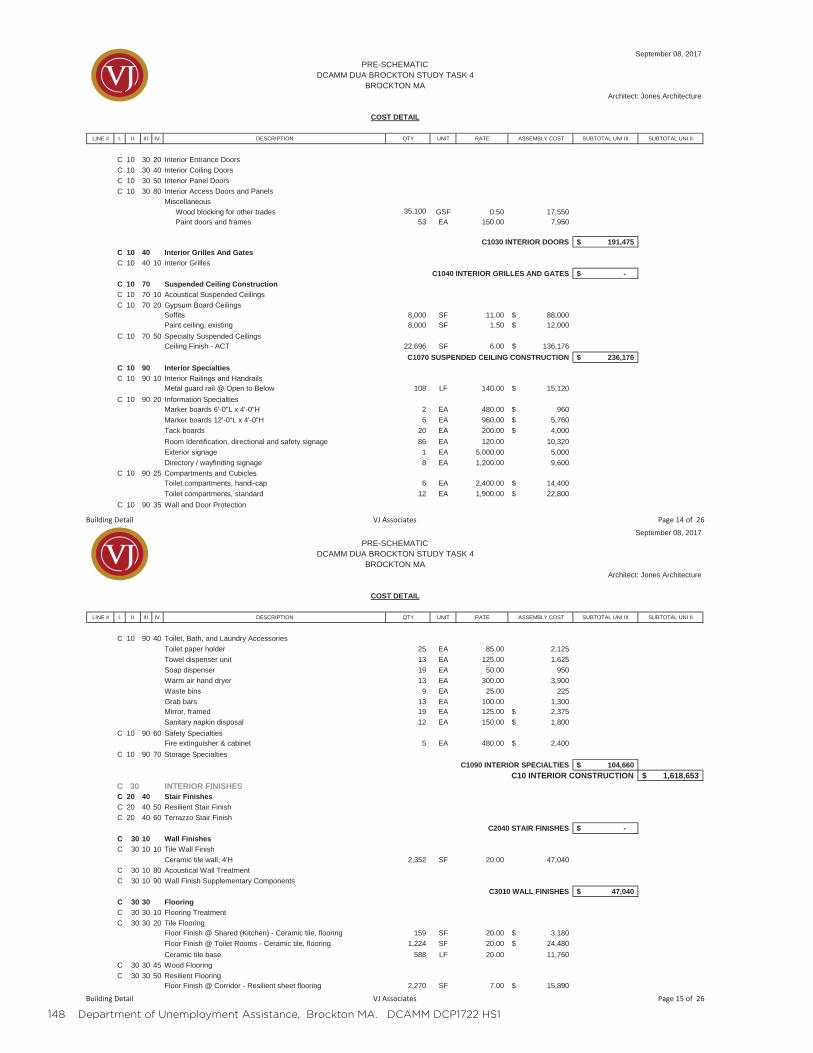
148 Department of Unemployment Assistance, Brockton MA. DCAMM DCP1722 HS1
LINE # I. II. III. IV. DESCRIPTION QTY UNIT RATE ASSEMBLY COST SUBTOTAL UNI III. SUBTOTAL UNI II.
September 08, 2017PRE-SCHEMATIC
DCAMM DUA BROCKTON STUDY TASK 4BROCKTON MA
Architect: Jones Architecture
COST DETAIL
C 10 30 20 Interior Entrance DoorsC 10 30 40 Interior Coiling DoorsC 10 30 50 Interior Panel DoorsC 10 30 80 Interior Access Doors and Panels
MiscellaneousWood blocking for other trades 35,100 GSF 0.50 17,550Paint doors and frames 53 EA 150.00 7,950
C1030 INTERIOR DOORS 191,475$C 10 40 Interior Grilles And GatesC 10 40 10 Interior Grilles
C1040 INTERIOR GRILLES AND GATES -$C 10 70 Suspended Ceiling ConstructionC 10 70 10 Acoustical Suspended CeilingsC 10 70 20 Gypsum Board Ceilings
Soffits 8,000 SF 11.00 88,000$ Paint ceiling, existing 8,000 SF 1.50 12,000$
C 10 70 50 Specialty Suspended CeilingsCeiling Finish - ACT 22,696 SF 6.00 136,176$
C1070 SUSPENDED CEILING CONSTRUCTION 236,176$C 10 90 Interior SpecialtiesC 10 90 10 Interior Railings and Handrails
Metal guard rail @ Open to Below 108 LF 140.00 15,120$C 10 90 20 Information Specialties
Marker boards 6'-0"L x 4'-0"H 2 EA 480.00 960$Marker boards 12'-0"L x 4'-0"H 6 EA 960.00 5,760$Tack boards 20 EA 200.00 4,000$Room Identification, directional and safety signage 86 EA 120.00 10,320Exterior signage 1 EA 5,000.00 5,000Directory / wayfinding signage 8 EA 1,200.00 9,600
C 10 90 25 Compartments and CubiclesToilet compartments, handi-cap 6 EA 2,400.00 14,400$Toilet compartments, standard 12 EA 1,900.00 22,800$
C 10 90 35 Wall and Door Protection
Building Detail VJ Associates Page 14 of 26
LINE # I. II. III. IV. DESCRIPTION QTY UNIT RATE ASSEMBLY COST SUBTOTAL UNI III. SUBTOTAL UNI II.
September 08, 2017PRE-SCHEMATIC
DCAMM DUA BROCKTON STUDY TASK 4BROCKTON MA
Architect: Jones Architecture
COST DETAIL
C 10 90 40 Toilet, Bath, and Laundry AccessoriesToilet paper holder 25 EA 85.00 2,125Towel dispenser unit 13 EA 125.00 1,625Soap dispenser 19 EA 50.00 950Warm air hand dryer 13 EA 300.00 3,900Waste bins 9 EA 25.00 225Grab bars 13 EA 100.00 1,300Mirror, framed 19 EA 125.00 2,375$Sanitary napkin disposal 12 EA 150.00 1,800$
C 10 90 60 Safety SpecialtiesFire extinguisher & cabinet 5 EA 480.00 2,400$
C 10 90 70 Storage SpecialtiesC1090 INTERIOR SPECIALTIES 104,660$
C10 INTERIOR CONSTRUCTION 1,618,653$ C 30 INTERIOR FINISHESC 20 40 Stair FinishesC 20 40 50 Resilient Stair FinishC 20 40 60 Terrazzo Stair Finish
C2040 STAIR FINISHES -$C 30 10 Wall FinishesC 30 10 10 Tile Wall Finish
Ceramic tile wall, 4'H 2,352 SF 20.00 47,040C 30 10 80 Acoustical Wall TreatmentC 30 10 90 Wall Finish Supplementary Components
C3010 WALL FINISHES 47,040$C 30 30 FlooringC 30 30 10 Flooring TreatmentC 30 30 20 Tile Flooring
Floor Finish @ Shared (Kitchen) - Ceramic tile, flooring 159 SF 20.00 3,180$Floor Finish @ Toilet Rooms - Ceramic tile, flooring 1,224 SF 20.00 24,480$Ceramic tile base 588 LF 20.00 11,760
C 30 30 45 Wood FlooringC 30 30 50 Resilient Flooring
Floor Finish @ Corridor - Resilient sheet flooring 2,270 SF 7.00 15,890$
Building Detail VJ Associates Page 15 of 26
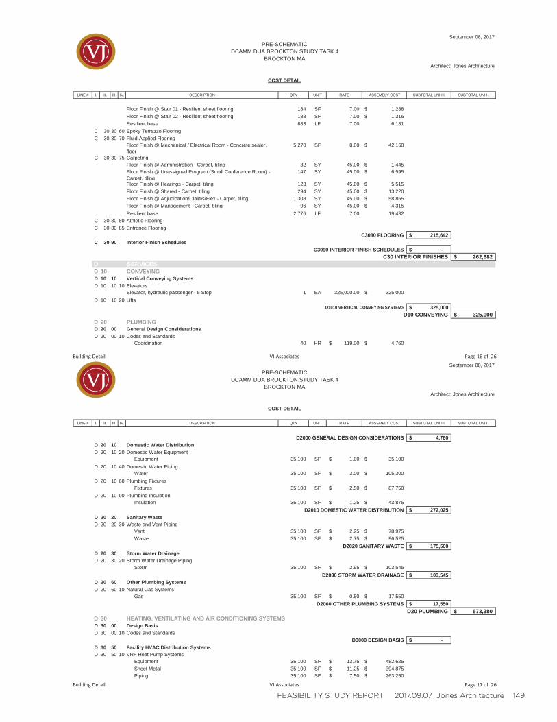
FEASIBILITY STUDY REPORT 2017.09.07 Jones Architecture 149
LINE # I. II. III. IV. DESCRIPTION QTY UNIT RATE ASSEMBLY COST SUBTOTAL UNI III. SUBTOTAL UNI II.
September 08, 2017PRE-SCHEMATIC
DCAMM DUA BROCKTON STUDY TASK 4BROCKTON MA
Architect: Jones Architecture
COST DETAIL
Floor Finish @ Stair 01 - Resilient sheet flooring 184 SF 7.00 1,288$Floor Finish @ Stair 02 - Resilient sheet flooring 188 SF 7.00 1,316$Resilient base 883 LF 7.00 6,181
C 30 30 60 Epoxy Terrazzo FlooringC 30 30 70 Fluid-Applied Flooring
Floor Finish @ Mechanical / Electrical Room - Concrete sealer, floor
5,270 SF 8.00 42,160$
C 30 30 75 CarpetingFloor Finish @ Administration - Carpet, tiling 32 SY 45.00 1,445$ Floor Finish @ Unassigned Program (Small Conference Room) - Carpet, tiling
147 SY 45.00 6,595$
Floor Finish @ Hearings - Carpet, tiling 123 SY 45.00 5,515$Floor Finish @ Shared - Carpet, tiling 294 SY 45.00 13,220$Floor Finish @ Adjudication/Claims/Flex - Carpet, tiling 1,308 SY 45.00 58,865$Floor Finish @ Management - Carpet, tiling 96 SY 45.00 4,315$Resilient base 2,776 LF 7.00 19,432
C 30 30 80 Athletic FlooringC 30 30 85 Entrance Flooring
C3030 FLOORING 215,642$C 30 90 Interior Finish Schedules
C3090 INTERIOR FINISH SCHEDULES -$C30 INTERIOR FINISHES 262,682$
D SERVICESD 10 CONVEYINGD 10 10 Vertical Conveying SystemsD 10 10 10 Elevators
Elevator, hydraulic passenger - 5 Stop 1 EA 325,000.00 325,000$D 10 10 20 Lifts
D1010 VERTICAL CONVEYING SYSTEMS 325,000$D10 CONVEYING 325,000$
D 20 PLUMBINGD 20 00 General Design ConsiderationsD 20 00 10 Codes and Standards
Coordination 40 HR 119.00$ 4,760$
Building Detail VJ Associates Page 16 of 26
LINE # I. II. III. IV. DESCRIPTION QTY UNIT RATE ASSEMBLY COST SUBTOTAL UNI III. SUBTOTAL UNI II.
September 08, 2017PRE-SCHEMATIC
DCAMM DUA BROCKTON STUDY TASK 4BROCKTON MA
Architect: Jones Architecture
COST DETAIL
D2000 GENERAL DESIGN CONSIDERATIONS 4,760$D 20 10 Domestic Water DistributionD 20 10 20 Domestic Water Equipment
Equipment 35,100 SF 1.00$ 35,100$D 20 10 40 Domestic Water Piping
Water 35,100 SF 3.00$ 105,300$D 20 10 60 Plumbing Fixtures
Fixtures 35,100 SF 2.50$ 87,750$D 20 10 90 Plumbing Insulation
Insulation 35,100 SF 1.25$ 43,875$D2010 DOMESTIC WATER DISTRIBUTION 272,025$
D 20 20 Sanitary WasteD 20 20 30 Waste and Vent Piping
Vent 35,100 SF 2.25$ 78,975$Waste 35,100 SF 2.75$ 96,525$
D2020 SANITARY WASTE 175,500$D 20 30 Storm Water DrainageD 20 30 20 Storm Water Drainage Piping
Storm 35,100 SF 2.95$ 103,545$D2030 STORM WATER DRAINAGE 103,545$
D 20 60 Other Plumbing SystemsD 20 60 10 Natural Gas Systems
Gas 35,100 SF 0.50$ 17,550$D2060 OTHER PLUMBING SYSTEMS 17,550$
D20 PLUMBING 573,380$ D 30 HEATING, VENTILATING AND AIR CONDITIONING SYSTEMSD 30 00 Design BasisD 30 00 10 Codes and Standards
D3000 DESIGN BASIS -$D 30 50 Facility HVAC Distribution SystemsD 30 50 10 VRF Heat Pump Systems
Equipment 35,100 SF 13.75$ 482,625$Sheet Metal 35,100 SF 11.25$ 394,875$Piping 35,100 SF 7.50$ 263,250$
Building Detail VJ Associates Page 17 of 26
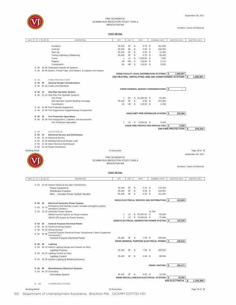
150 Department of Unemployment Assistance, Brockton MA. DCAMM DCP1722 HS1
LINE # I. II. III. IV. DESCRIPTION QTY UNIT RATE ASSEMBLY COST SUBTOTAL UNI III. SUBTOTAL UNI II.
September 08, 2017PRE-SCHEMATIC
DCAMM DUA BROCKTON STUDY TASK 4BROCKTON MA
Architect: Jones Architecture
COST DETAIL
Insulation 35,100 SF 5.75$ 201,825$Controls 35,100 SF 5.50$ 193,050$Start Up 35,100 SF 0.35$ 12,285$Testing Adjusting & Balancing 35,100 SF 0.75$ 26,325$Crane 1 LS 7,500.00$ 7,500$Rigging 48 HR 119.00$ 5,712$Coordination 80 HR 119.00$ 9,520$
D 30 50 50 Dedicated Outside Air SystemsD 30 30 90 Boilers, Finned Tube, Unit Heaters, & Cabinet Unit Heaters
D3050 FACILITY HVAC DISTRIBUTION SYSTEMS 1,596,967$D30 HEATING, VENTILATING AND AIR CONDITIONING SYSTEMS 1,596,967$
D 40 FIRE-PROTECTIOND 40 00 General Design ConsiderationsD 40 00 10 Codes and Standards
D4000 GENERAL DESIGN CONSIDERATIONS -$D 40 10 Wet-Pipe Sprinkler SystemD 40 10 10 Wet-Pipe Fire Sprinkler Systems
Fire Pump 1 EA 62,350.00$ 62,350$Wet Sprinkler System Building Coverage 35,100 SF 4.50$ 157,950$Coordination 40 HR 119.00$ 4,760$
D 40 10 80 Fire Protection EquipmentD 40 10 90 Fire Suppression Supplementary Components
D4010 WET-PIPE SPRINKLER SYSTEM 225,060$D 40 30 Fire Protection SpecialtiesD 40 30 30 Fire extinguishers, Cabinets, and Accessories
Fire Protection Specialties 1 LS 9,250.00$ 9,250$D4030 FIRE PROTECTION SPECIALTIES 9,250$
D40 FIRE-PROTECTION 234,310$ D 50 ELECTRICALD 50 10 Electrical Service and DistributionD 50 10 10 Electrical ServiceD 50 10 20 Building Electrical Design LoadD 50 10 30 Main Electrical SwitchboardD 50 10 40 Power Distribution
Building Detail VJ Associates Page 18 of 26
LINE # I. II. III. IV. DESCRIPTION QTY UNIT RATE ASSEMBLY COST SUBTOTAL UNI III. SUBTOTAL UNI II.
September 08, 2017PRE-SCHEMATIC
DCAMM DUA BROCKTON STUDY TASK 4BROCKTON MA
Architect: Jones Architecture
COST DETAIL
D 50 10 50 Interior Electrical Dry-type TransformersPower Equipment 35,100 SF 3.14$ 110,334$Distribution Feeders 35,100 SF 4.25$ 149,001$Misc. - Includes Power System Studies 35,100 SF 4.32$ 151,491$
D5010 ELECTRICAL SERVICE AND DISTRIBUTION 410,826$D 50 20 Electrical Generator Power System
D 50 20 10 Emergency and Standby Loads ( includes emergency panels, emergency feeders )
D 50 20 20 Generator Power System w/ Site30KVA Inverter System w/ Power Feeders 1 LS 50,000.00$ 50,000$30KVA UPS System w/ Power Feeders 1 LS 70,000.00$ 70,000$
D5020 ELECTRICAL GENERATOR POWER SYSTEM 120,000$D 50 30 General Purpose Electrical PowerD 50 30 10 Electrical Wiring SystemD 50 30 50 Wiring Devices
D 50 30 90 General Purpose Electrical Power Components ( Mech Equipment Connections )
General Purpose Electrical Power 35,100 SF 7.09$ 248,816$D5030 GENERAL PURPOSE ELECTRICAL POWER 248,816$
D 50 40 LightingD 50 40 10 Interior Lighting Design and Fixtures w/ Cktry
Lighting Fixtures 35,100 SF 7.68$ 269,552$D 50 40 20 Lighting Control w/ Cktry
Lighting Control 35,100 SF 2.48$ 86,919$D 50 40 30 Exterior Lighting @ Building Entrances
D5040 LIGHTING 356,471$D 50 80 Miscellaneous Electrical SystemsD 50 80 10 Grounding
Grounding System 35,100 SF 0.55$ 19,256$D5080 MISCELLANEOUS ELECTRICAL SYSTEMS 19,256$
D50 ELECTRICAL 1,155,369$ D 50 COMMUNICATIONS
Building Detail VJ Associates Page 19 of 26
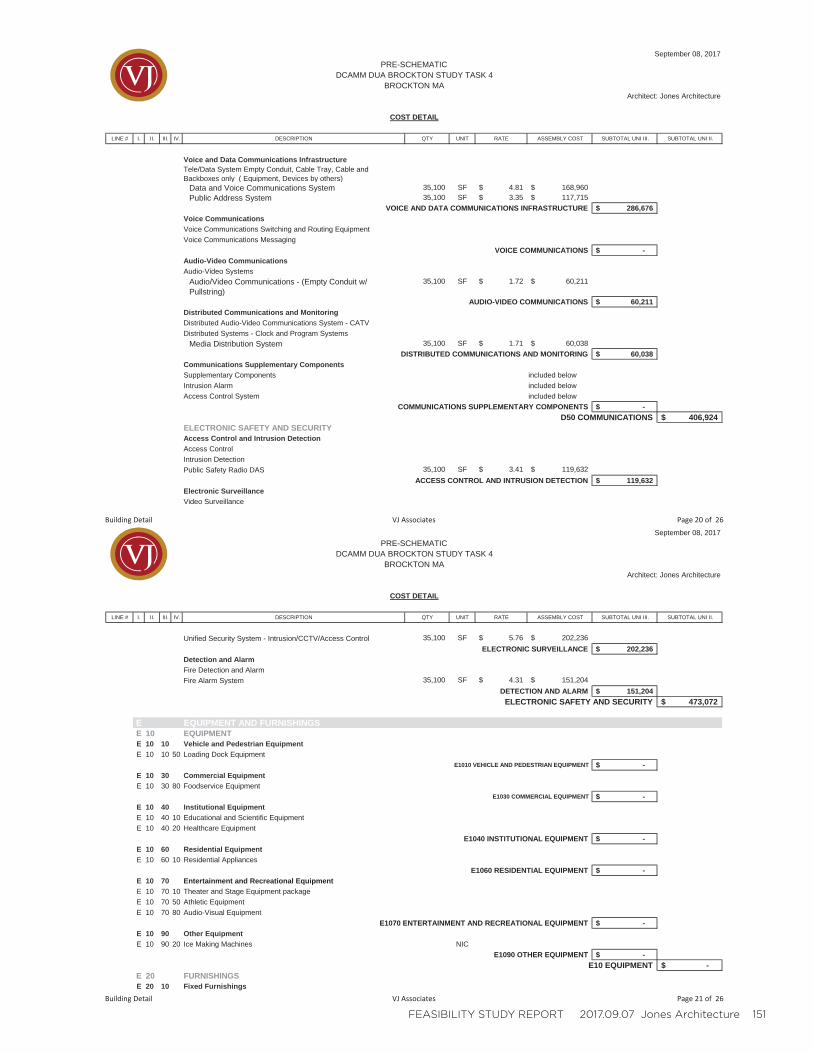
FEASIBILITY STUDY REPORT 2017.09.07 Jones Architecture 151
LINE # I. II. III. IV. DESCRIPTION QTY UNIT RATE ASSEMBLY COST SUBTOTAL UNI III. SUBTOTAL UNI II.
September 08, 2017PRE-SCHEMATIC
DCAMM DUA BROCKTON STUDY TASK 4BROCKTON MA
Architect: Jones Architecture
COST DETAIL
Voice and Data Communications InfrastructureTele/Data System Empty Conduit, Cable Tray, Cable and Backboxes only ( Equipment, Devices by others)
Data and Voice Communications System 35,100 SF 4.81$ 168,960$Public Address System 35,100 SF 3.35$ 117,715$
VOICE AND DATA COMMUNICATIONS INFRASTRUCTURE 286,676$Voice CommunicationsVoice Communications Switching and Routing EquipmentVoice Communications Messaging
VOICE COMMUNICATIONS -$Audio-Video CommunicationsAudio-Video Systems
Audio/Video Communications - (Empty Conduit w/ Pullstring)
35,100 SF 1.72$ 60,211$
AUDIO-VIDEO COMMUNICATIONS 60,211$Distributed Communications and MonitoringDistributed Audio-Video Communications System - CATVDistributed Systems - Clock and Program Systems
Media Distribution System 35,100 SF 1.71$ 60,038$ DISTRIBUTED COMMUNICATIONS AND MONITORING 60,038$
Communications Supplementary ComponentsSupplementary Components included belowIntrusion Alarm included belowAccess Control System included below
COMMUNICATIONS SUPPLEMENTARY COMPONENTS -$D50 COMMUNICATIONS 406,924$
ELECTRONIC SAFETY AND SECURITYAccess Control and Intrusion DetectionAccess Control mIntrusion DetectionPublic Safety Radio DAS 35,100 SF 3.41$ 119,632$
ACCESS CONTROL AND INTRUSION DETECTION 119,632$Electronic SurveillanceVideo Surveillance
Building Detail VJ Associates Page 20 of 26
LINE # I. II. III. IV. DESCRIPTION QTY UNIT RATE ASSEMBLY COST SUBTOTAL UNI III. SUBTOTAL UNI II.
September 08, 2017PRE-SCHEMATIC
DCAMM DUA BROCKTON STUDY TASK 4BROCKTON MA
Architect: Jones Architecture
COST DETAIL
Unified Security System - Intrusion/CCTV/Access Control 35,100 SF 5.76$ 202,236$ ELECTRONIC SURVEILLANCE 202,236$
Detection and AlarmFire Detection and AlarmFire Alarm System 35,100 SF 4.31$ 151,204$
DETECTION AND ALARM 151,204$ ELECTRONIC SAFETY AND SECURITY 473,072$
E EQUIPMENT AND FURNISHINGSE 10 EQUIPMENTE 10 10 Vehicle and Pedestrian EquipmentE 10 10 50 Loading Dock Equipment
E1010 VEHICLE AND PEDESTRIAN EQUIPMENT -$E 10 30 Commercial EquipmentE 10 30 80 Foodservice Equipment
E1030 COMMERCIAL EQUIPMENT -$E 10 40 Institutional EquipmentE 10 40 10 Educational and Scientific EquipmentE 10 40 20 Healthcare Equipment
E1040 INSTITUTIONAL EQUIPMENT -$E 10 60 Residential EquipmentE 10 60 10 Residential Appliances
E1060 RESIDENTIAL EQUIPMENT -$E 10 70 Entertainment and Recreational EquipmentE 10 70 10 Theater and Stage Equipment packageE 10 70 50 Athletic EquipmentE 10 70 80 Audio-Visual Equipment
E1070 ENTERTAINMENT AND RECREATIONAL EQUIPMENT -$E 10 90 Other EquipmentE 10 90 20 Ice Making Machines NIC
E1090 OTHER EQUIPMENT -$E10 EQUIPMENT -$
E 20 FURNISHINGSE 20 10 Fixed Furnishings
Building Detail VJ Associates Page 21 of 26
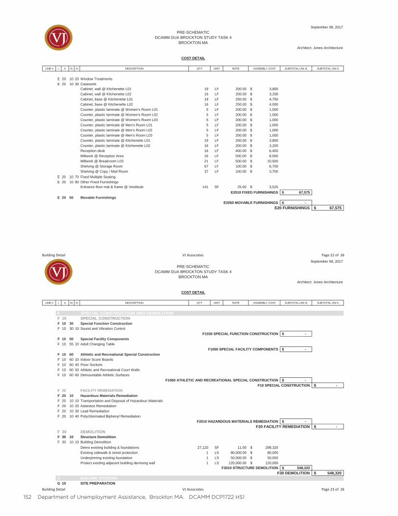
152 Department of Unemployment Assistance, Brockton MA. DCAMM DCP1722 HS1
LINE # I. II. III. IV. DESCRIPTION QTY UNIT RATE ASSEMBLY COST SUBTOTAL UNI III. SUBTOTAL UNI II.
September 08, 2017PRE-SCHEMATIC
DCAMM DUA BROCKTON STUDY TASK 4BROCKTON MA
Architect: Jones Architecture
COST DETAIL
E 20 10 20 Window TreatmentsE 20 10 30 Casework
Cabinet, wall @ Kitchenette L01 19 LF 200.00 3,800$Cabinet, wall @ Kitchenette L02 16 LF 200.00 3,200$Cabinet, base @ Kitchenette L01 19 LF 250.00 4,750$Cabinet, base @ Kitchenette L02 16 LF 250.00 4,000$Counter, plastic laminate @ Women's Room L01 5 LF 200.00 1,000$Counter, plastic laminate @ Women's Room L02 5 LF 200.00 1,000$Counter, plastic laminate @ Women's Room L03 5 LF 200.00 1,000$Counter, plastic laminate @ Men's Room L01 5 LF 200.00 1,000$Counter, plastic laminate @ Men's Room L02 5 LF 200.00 1,000$Counter, plastic laminate @ Men's Room L03 5 LF 200.00 1,000$Counter, plastic laminate @ Kitchenette L01 19 LF 200.00 3,800$Counter, plastic laminate @ Kitchenette L02 16 LF 200.00 3,200$Reception desk 16 LF 400.00 6,400$Millwork @ Reception Area 16 LF 500.00 8,000$Millwork @ Breakroom L03 21 LF 500.00 10,500$Shelving @ Storage Room 67 LF 100.00 6,700$Shelving @ Copy / Mail Room 37 LF 100.00 3,700$
E 20 10 70 Fixed Multiple SeatingE 20 10 90 Other Fixed Furnishings
Entrance floor mat & frame @ Vestibule 141 SF 25.00 3,525$E2010 FIXED FURNISHINGS 67,575$
E 20 50 Movable FurnishingsE2050 MOVABLE FURNISHINGS -$
E20 FURNISHINGS 67,575$
Building Detail VJ Associates Page 22 of 26
LINE # I. II. III. IV. DESCRIPTION QTY UNIT RATE ASSEMBLY COST SUBTOTAL UNI III. SUBTOTAL UNI II.
September 08, 2017PRE-SCHEMATIC
DCAMM DUA BROCKTON STUDY TASK 4BROCKTON MA
Architect: Jones Architecture
COST DETAIL
F SPECIAL CONSTRUCTION AND DEMOLITIONF 10 SPECIAL CONSTRUCTIONF 10 30 Special Function ConstructionF 10 30 10 Sound and Vibration Control
F1030 SPECIAL FUNCTION CONSTRUCTION -$F 10 50 Special Facility ComponentsF 10 55 10 Adult Changing Table
F1050 SPECIAL FACILITY COMPONENTS -$F 10 60 Athletic and Recreational Special ConstructionF 10 60 10 Indoor Score BoardsF 10 60 40 Floor SocketsF 10 60 50 Athletic and Recreational Court WallsF 10 60 60 Demountable Athletic Surfaces
F1060 ATHLETIC AND RECREATIONAL SPECIAL CONSTRUCTION -$F10 SPECIAL CONSTRUCTION -$
F 20 FACILITY REMEDIATIONF 20 10 Hazardous Materials RemediationF 20 10 10 Transportation and Disposal of Hazardous MaterialsF 20 10 20 Asbestos RemediationF 20 10 30 Lead RemediationF 20 10 40 Polychlorinated Biphenyl Remediation
F2010 HAZARDOUS MATERIALS REMEDIATION -$F20 FACILITY REMEDIATION -$
F 30 DEMOLITIONF 30 10 Structure DemolitionF 30 10 10 Building Demolition
Demo existing building & foundations 27,120 SF 11.00 298,320$Existing sidewalk & street protection 1 LS 80,000.00 80,000$Underpinning existing foundation 1 LS 50,000.00 50,000$Protect existing adjacent building demising wall 1 LS 120,000.00 120,000$
F3010 STRUCTURE DEMOLITION 548,320$F30 DEMOLITION 548,320$
G BUILDING SITEWORKG 10 SITE PREPARATION
Building Detail VJ Associates Page 23 of 26
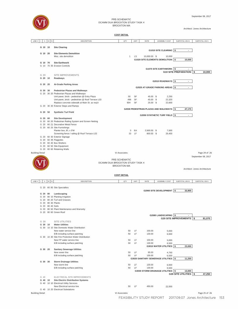
FEASIBILITY STUDY REPORT 2017.09.07 Jones Architecture 153
LINE # I. II. III. IV. DESCRIPTION QTY UNIT RATE ASSEMBLY COST SUBTOTAL UNI III. SUBTOTAL UNI II.
September 08, 2017PRE-SCHEMATIC
DCAMM DUA BROCKTON STUDY TASK 4BROCKTON MA
Architect: Jones Architecture
COST DETAIL
G 10 10 Site ClearingG1010 SITE CLEARING -$
G 10 20 Site Elements DemolitionMisc. site demolition 1 LS 10,000.00 10,000$
G1020 SITE ELEMENTS DEMOLITION 10,000$G 10 70 Site EarthworkG 10 70 35 Erosion Controls
G1070 SITE EARTHWORK -$G10 SITE PREPARATION 10,000$
G 20 SITE IMPROVEMENTSG 20 10 Roadways
G2010 ROADWAYS -$G 20 20 At-Grade Parking Areas
G2020 AT-GRADE PARKING AREAS -$G 20 30 Pedestrian Plazas and WalkwaysG 20 30 20 Pedestrian Plazas and Walkways
Unit paver, brick - pedestrian @ Entry Plaza 50 SF 45.00 2,250$Unit paver, brick - pedestrian @ Roof Terrace L03 496 SF 45.00 22,320$Replace concrete sidewalk at Main St. as req'd 904 SF 25.00 22,600$
G 20 30 30 Exterior Steps and RampsG2030 PEDESTRIAN PLAZAS AND WALKWAYS 47,170$
G 20 50 Synthetic Turf FieldG2050 SYNTHETIC TURF FIELD -$
G 20 60 Site DevelopmentG 20 60 20 Pedestrian Railing System and Screen NettingG 20 60 21 Decorative Metal FenceG 20 60 25 Site Furnishings
Planter box, 8'L x 3'W 3 EA 2,500.00 7,500$Screening fence / railing @ Roof Terrace L03 33 LF 800.00 26,400$
G 20 60 30 Exterior SignageG 20 60 35 FlagpolesG 20 60 40 Bus SheltersG 20 60 50 Site EquipmentG 20 60 60 Retaining Walls
Building Detail VJ Associates Page 24 of 26
LINE # I. II. III. IV. DESCRIPTION QTY UNIT RATE ASSEMBLY COST SUBTOTAL UNI III. SUBTOTAL UNI II.
September 08, 2017PRE-SCHEMATIC
DCAMM DUA BROCKTON STUDY TASK 4BROCKTON MA
Architect: Jones Architecture
COST DETAIL
G 20 60 85 Site SpecialtiesG2060 SITE DEVELOPMENT 33,900$
G 20 80 LandscapingG 20 80 10 Planting IrrigationG 20 80 20 Turf and GrassesG 20 80 30 PlantsG 20 80 40 SoilsG 20 80 50 Plant Maintenance and WarrantyG 20 80 60 Green Roof
G2080 LANDSCAPING -$G20 SITE IMPROVEMENTS 81,070$
G 30 SITE UTILITIESG 30 10 Water UtilitiesG 30 10 10 Site Domestic Water Distribution
New water service line 50 LF 100.00 5,000E/B including surface patching 50 LF 130.00 6,500
G 30 10 30 Site Fire Protection Water DistributionNew FP water service line 50 LF 100.00 5,000E/B including surface patching 50 LF 130.00 6,500
G3010 WATER UTILITIES 23,000$G 30 20 Sanitary Sewerage Utilities
New sewer line 50 LF 95.00 4,750E/B including surface patching 50 LF 130.00 6,500
G3020 SANITARY SEWERAGE UTILITIES 11,250$G 30 30 Storm Drainage Utilities
New storm line 50 LF 130.00 6,500E/B including surface patching 50 LF 130.00 6,500
G3030 STORM DRAINAGE UTILITIES 13,000$G30 SITE UTILITIES 47,250$
G 40 ELECTRICAL SITE IMPROVEMENTSG 40 10 Site Electric Distribution SystemsG 40 10 10 Electrical Utility Services
New Electrical service line 50 LF 450.00 22,500G 40 10 20 Electrical Substations
Building Detail VJ Associates Page 25 of 26
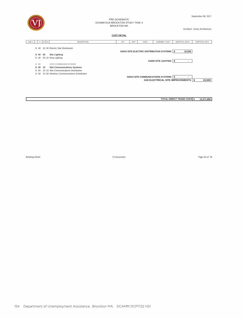
154 Department of Unemployment Assistance, Brockton MA. DCAMM DCP1722 HS1
LINE # I. II. III. IV. DESCRIPTION QTY UNIT RATE ASSEMBLY COST SUBTOTAL UNI III. SUBTOTAL UNI II.
September 08, 2017PRE-SCHEMATIC
DCAMM DUA BROCKTON STUDY TASK 4BROCKTON MA
Architect: Jones Architecture
COST DETAIL
G 40 10 30 Electric Site DistributionG4010 SITE ELECTRIC DISTRIBUTION SYSTEMS 22,500$
G 40 50 Site LightingG 40 50 10 Area Lighting
G4050 SITE LIGHTING -$G 50 SITE COMMUNICATIONSG 50 10 Site Communications SystemsG 50 10 10 Site Communications DistributionG 50 10 50 Wireless Communications Distribution
G5010 SITE COMMUNICATIONS SYSTEMS -$G40 ELECTRICAL SITE IMPROVEMENTS 22,500$
12,271,868$TOTAL DIRECT TRADE COST
Building Detail VJ Associates Page 26 of 26

FEASIBILITY STUDY REPORT 2017.09.07 Jones Architecture 155
156 Department of Unemployment Assistance, Brockton MA. DCAMM DCP1722 HS1
J. PROJECT SCHEDULE

FEASIBILITY STUDY REPORT 2017.09.07 Jones Architecture 157
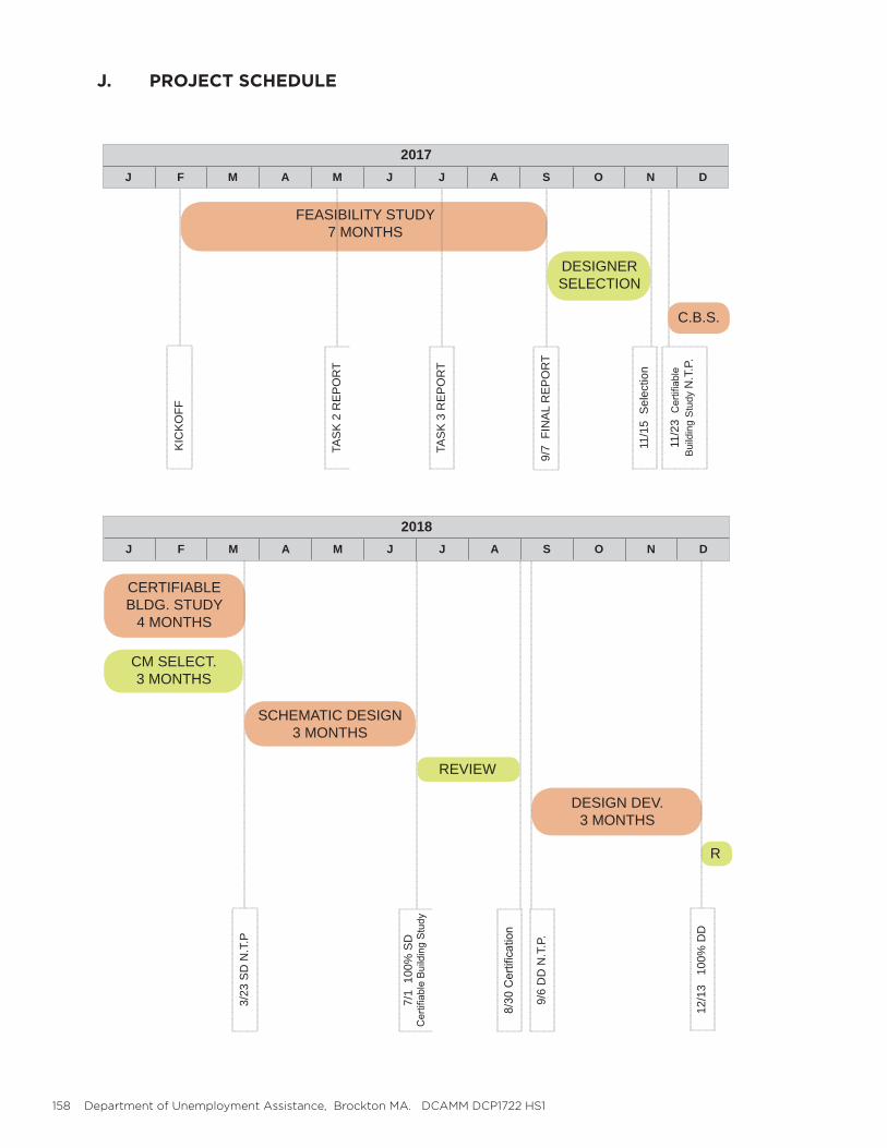
158 Department of Unemployment Assistance, Brockton MA. DCAMM DCP1722 HS1
J. PROJECT SCHEDULE
2017J F M A M J J A S O N D
FEASIBILITY STUDY7 MONTHS
DESIGNERSELECTION
KIC
KO
FF
TAS
K 2
RE
PO
RT
TAS
K 3
RE
PO
RT
9/7
FIN
AL
RE
PO
RT
11/2
3
Bui
ldin
g S
tudy
N.T
.P.
C.B.S.
2018J F M A M J J A S O N D
CERTIFIABLE BLDG. STUDY
4 MONTHS
3/23
SD
N.T
.P
7/1
100
% S
D
SCHEMATIC DESIGN3 MONTHS
DESIGN DEV.3 MONTHS
REVIEW
CM SELECT.3 MONTHS
R
9/6
DD
N.T
.P.
12/1
3 1
00%
DD
11/1
5 S
elec
tion
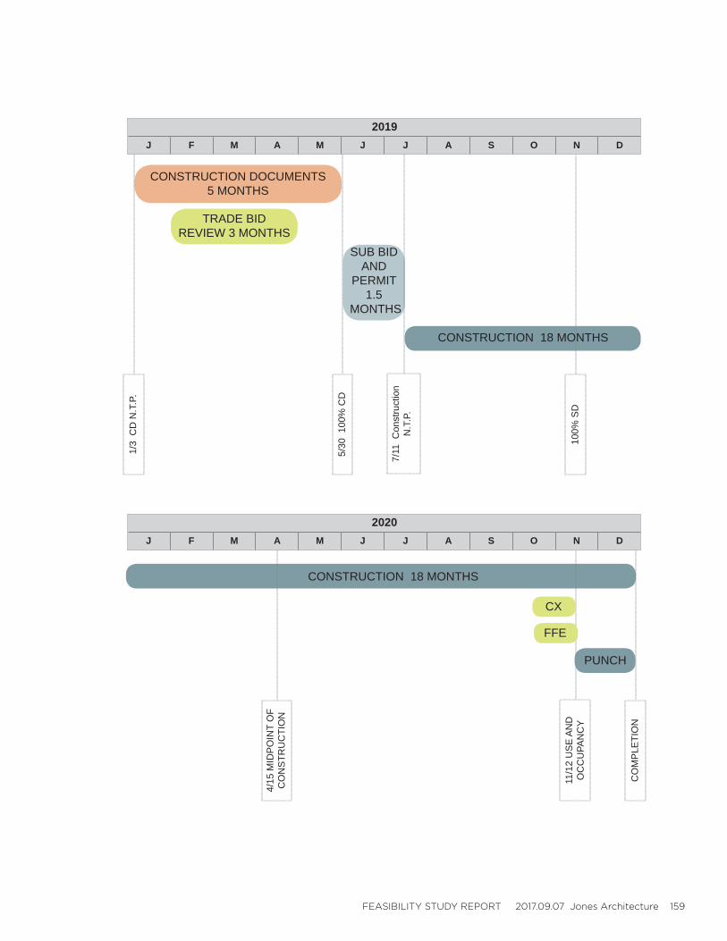
FEASIBILITY STUDY REPORT 2017.09.07 Jones Architecture 159
CONSTRUCTION 18 MONTHS
2019J F M A M J J A S O N D
CONSTRUCTION DOCUMENTS5 MONTHS
5/30
100
% C
D
7/11
Con
stru
ctio
n N
.T.P
.
100%
SD
1/3
CD
N.T
.P.
SUB BID AND
PERMIT1.5
MONTHS
CONSTRUCTION 18 MONTHS
2020J F M A M J J A S O N D
11/1
2 U
SE
AN
D
OC
CU
PAN
CY
CO
MP
LETI
ON
FFE
CX
PUNCH
TRADE BID REVIEW 3 MONTHS
4/15
MID
PO
INT
OF
CO
NS
TRU
CTI
ON

160 Department of Unemployment Assistance, Brockton MA. DCAMM DCP1722 HS1
TABLE OF CONTENTS
VOLUME 2 - APPENDIX
Contains information on the background of the study and the decision to move forward with the property at 226 Main Street. For additional information refer to Task 3 Report.
A. EXISTING CONDITIONS 1. Context Plan 2. 226 Main Street Floor Plans 3. 226 Main Street Existing Conditions Report
B. PLANNING 1. Investigation of Alternatives a. Introduction b. Planning Guidelines and Assumptions c. Building Systems Synopsis d. Planning Options Summary 2. 36 Main Street Preliminary Program Fit 3. 226 Main Street Preliminary Program Fit 4. 226 Main Street Expanded Planning Exercise

FEASIBILITY STUDY REPORT 2017.09.07 Jones Architecture 161

162 Department of Unemployment Assistance, Brockton MA. DCAMM DCP1722 HS1
A. EXISTING CONDITIONS

FEASIBILITY STUDY REPORT 2017.09.07 Jones Architecture 163
164 Department of Unemployment Assistance, Brockton MA. DCAMM DCP1722 HS1
A. EXISTING CONDITIONS
CONTEXT PLAN, BROCKTON MA
The two properties considered within this study are located in Brockton, MA along Main Street. 36 Main utilizes paid surface parking, while 226 offers a paid parking ga-rage. Both are be accessible by MBTA.
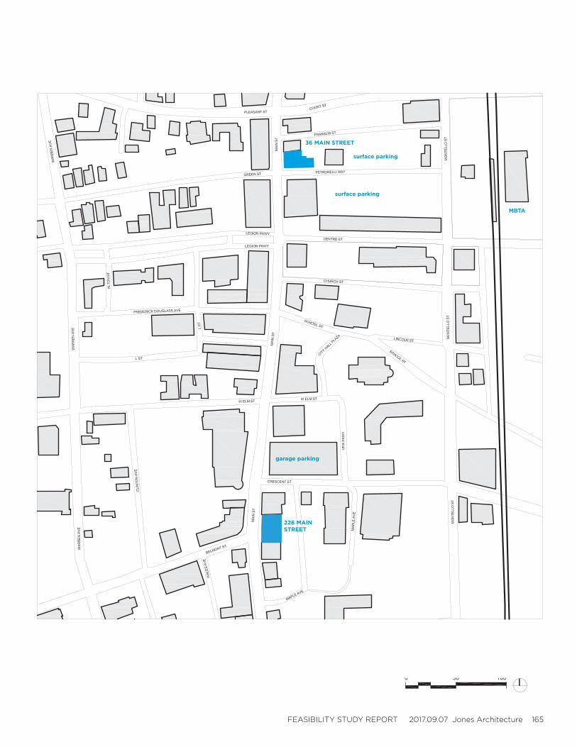
FEASIBILITY STUDY REPORT 2017.09.07 Jones Architecture 165
226 MAIN STREET
36 MAIN STREET
MBTA
surface parking
surface parking
garage parking
166 Department of Unemployment Assistance, Brockton MA. DCAMM DCP1722 HS1
A. EXISTING CONDITIONS
EXISTING CONDITIONS ANALYSIS
The property at 226 Main Street has been condemned and was not accessible at the time of this feasibility study. The most recent analysis of this building was performed in 2016 by Finegold Alexander Architects, found in the Appendix. The following assessment was pro-vided at that time:
During the course of this study the design team conducted investigations to review all ma-jor building components and systems. Information was collected by visiting the site and by reviewing the provided existing conditions drawings and previous study reports. While the Main Facade was in better than anticipated condition the majority of the building and sys-tems were found to be in poor condition and unsuitable for reuse.
The conclusion of this 2016 study was that the building at 226 Main Street should be demol-ished in its entirety with the possible exception of the front facade. This comparative study of 36 and 226 Main Street follows this direction as discussed in Section 6 Design Options.
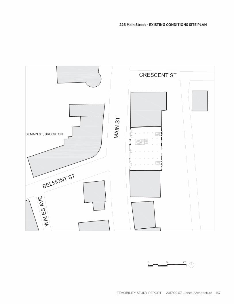
FEASIBILITY STUDY REPORT 2017.09.07 Jones Architecture 167
226 Main Street - EXISTING CONDITIONS SITE PLAN
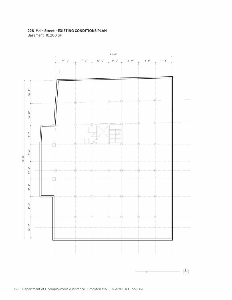
168 Department of Unemployment Assistance, Brockton MA. DCAMM DCP1722 HS1
226 Main Street - EXISTING CONDITIONS PLANBasement 10,200 SF
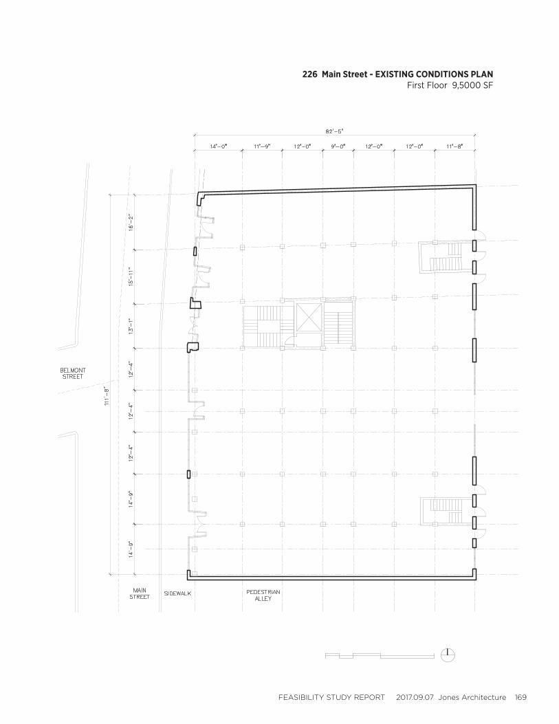
FEASIBILITY STUDY REPORT 2017.09.07 Jones Architecture 169
226 Main Street - EXISTING CONDITIONS PLANFirst Floor 9,5000 SF
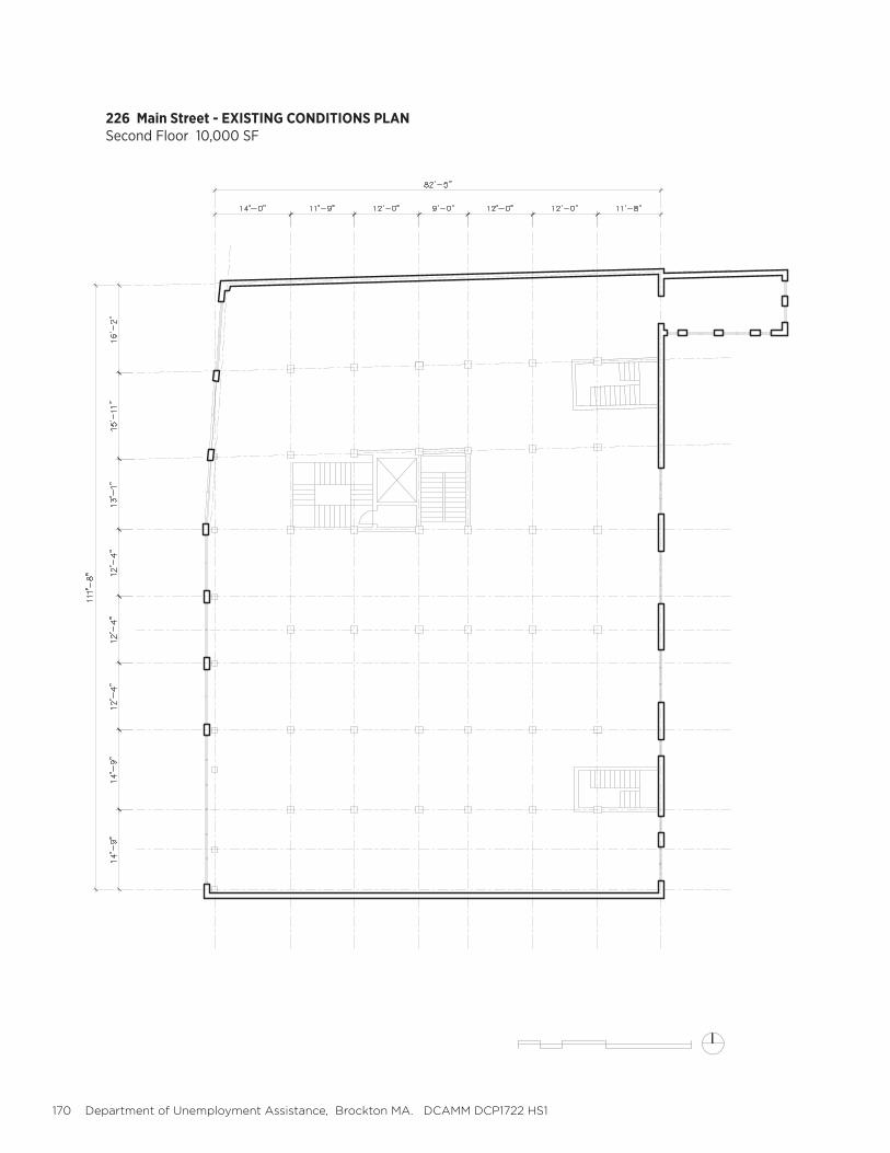
170 Department of Unemployment Assistance, Brockton MA. DCAMM DCP1722 HS1
226 Main Street - EXISTING CONDITIONS PLANSecond Floor 10,000 SF
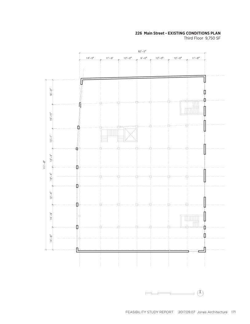
FEASIBILITY STUDY REPORT 2017.09.07 Jones Architecture 171
226 Main Street - EXISTING CONDITIONS PLANThird Floor 9,750 SF
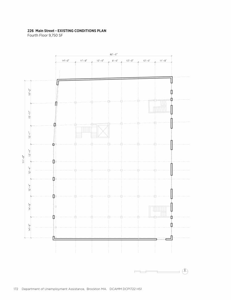
172 Department of Unemployment Assistance, Brockton MA. DCAMM DCP1722 HS1
226 Main Street - EXISTING CONDITIONS PLANFourth Floor 9,750 SF

FEASIBILITY STUDY REPORT 2017.09.07 Jones Architecture 173
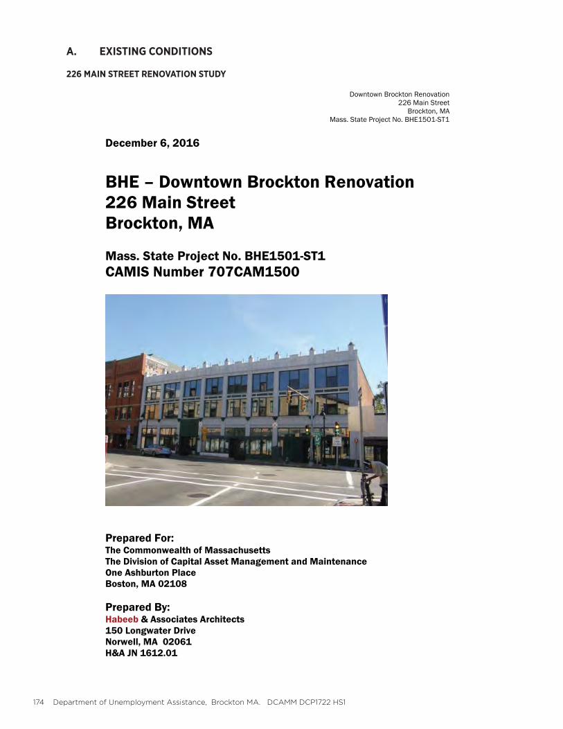
174 Department of Unemployment Assistance, Brockton MA. DCAMM DCP1722 HS1
A. EXISTING CONDITIONS
226 MAIN STREET RENOVATION STUDY

FEASIBILITY STUDY REPORT 2017.09.07 Jones Architecture 175
176 Department of Unemployment Assistance, Brockton MA. DCAMM DCP1722 HS1
FEASIBILITY STUDY REPORT 2017.09.07 Jones Architecture 177

178 Department of Unemployment Assistance, Brockton MA. DCAMM DCP1722 HS1
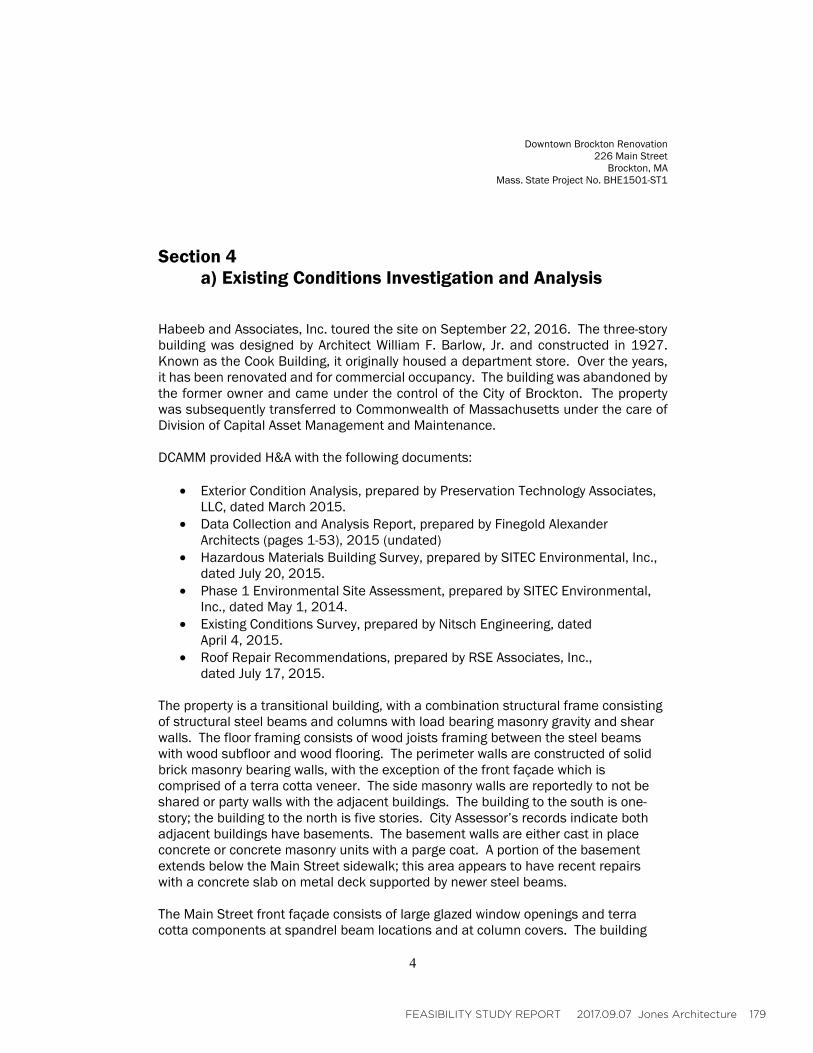
FEASIBILITY STUDY REPORT 2017.09.07 Jones Architecture 179
•
•
•
•
•
•
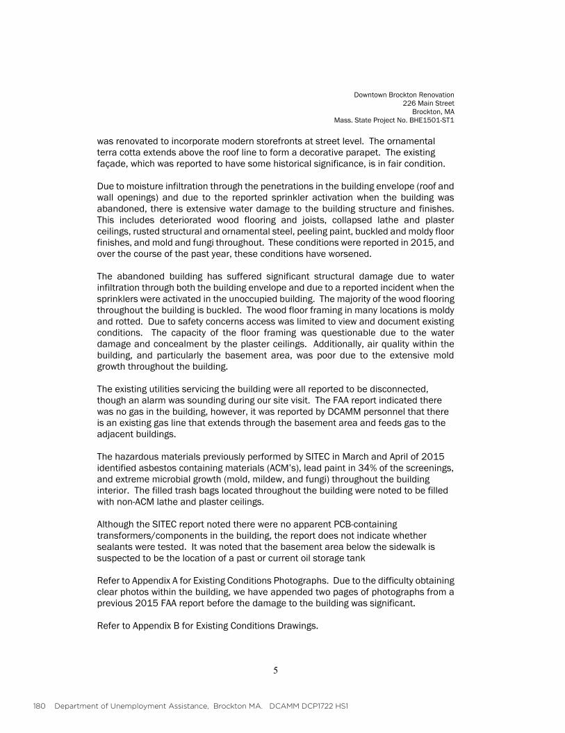
180 Department of Unemployment Assistance, Brockton MA. DCAMM DCP1722 HS1
FEASIBILITY STUDY REPORT 2017.09.07 Jones Architecture 181
182 Department of Unemployment Assistance, Brockton MA. DCAMM DCP1722 HS1
FEASIBILITY STUDY REPORT 2017.09.07 Jones Architecture 183
•
•
••
•
•
•
•
•
184 Department of Unemployment Assistance, Brockton MA. DCAMM DCP1722 HS1
•
•
••
•
•
••
FEASIBILITY STUDY REPORT 2017.09.07 Jones Architecture 185
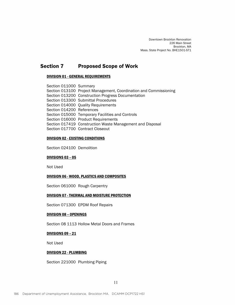
186 Department of Unemployment Assistance, Brockton MA. DCAMM DCP1722 HS1
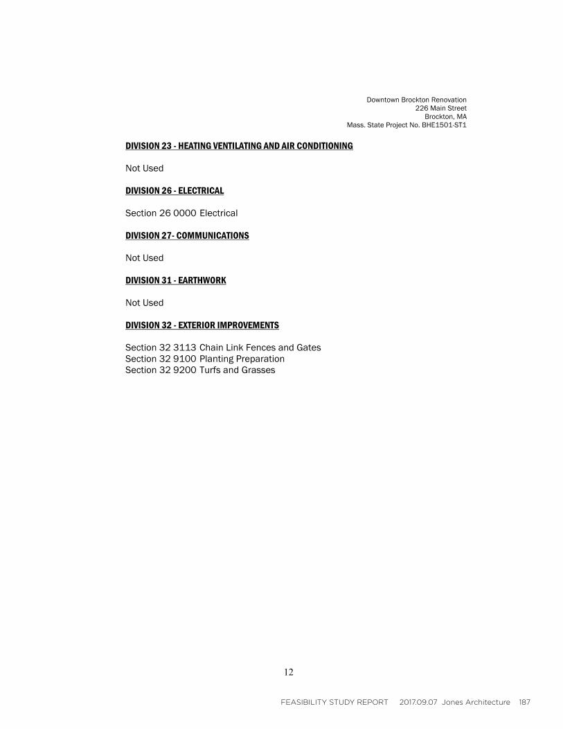
FEASIBILITY STUDY REPORT 2017.09.07 Jones Architecture 187
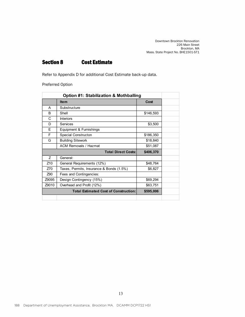
188 Department of Unemployment Assistance, Brockton MA. DCAMM DCP1722 HS1
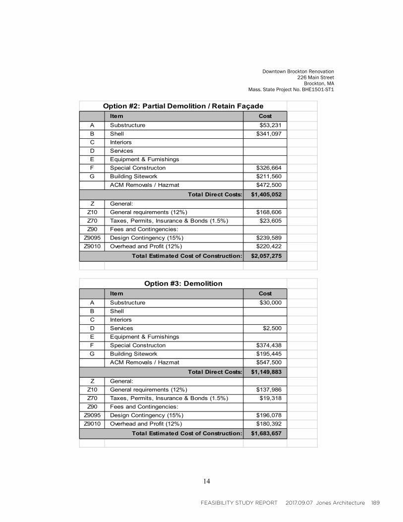
FEASIBILITY STUDY REPORT 2017.09.07 Jones Architecture 189

190 Department of Unemployment Assistance, Brockton MA. DCAMM DCP1722 HS1
B. INVESTIGATION OF ALTERNATIVES

FEASIBILITY STUDY REPORT 2017.09.07 Jones Architecture 191
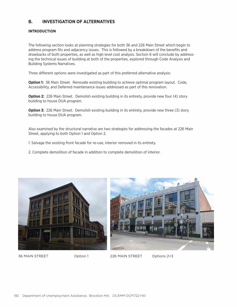
192 Department of Unemployment Assistance, Brockton MA. DCAMM DCP1722 HS1
B. INVESTIGATION OF ALTERNATIVES
INTRODUCTION
The following section looks at planning strategies for both 36 and 226 Main Street which begin to address program fits and adjacency issues. This is followed by a breakdown of the benefits and drawbacks of both properties, as well as high level cost analysis. Section 6 will conclude by address-ing the technical issues of building at both of the properties, explored through Code Analysis and Building Systems Narratives.
Three different options were investigated as part of this preferred alternative analysis:
Option 1: 36 Main Street. Renovate existing building to achieve optimal program layout. Code, Accessibility, and Deferred maintenance issues addressed as part of this renovation.
Option 2: 226 Main Street. Demolish existing building in its entirety, provide new four (4) story building to house DUA program.
Option 3: 226 Main Street. Demolish existing building in its entirety, provide new three (3) story building to house DUA program.
Also examined by the structural narrative are two strategies for addressing the facades at 226 Main Street, applying to both Option 1 and Option 2.
1. Salvage the existing front facade for re-use, interior removed in its entirety.
2. Complete demolition of facade in addition to complete demolition of interior.
36 MAIN STREET Option 1 226 MAIN STREET Options 2+3
FEASIBILITY STUDY REPORT 2017.09.07 Jones Architecture 193
B. INVESTIGATION OF ALTERNATIVES
PLANNING GUIDELINES
The following general planning guidelines were utilized when distributing program defined in Section 5 throughout the buildings at both 36 and 226 Main Street.
For the purposes of this planning study, the existing footprint was used as a background for 226 Main Street. It is understood that this existing building will be demolished and replaced (including all vertical circulation and infrastructure). The existing footprint is used only for reference at this time; this would be explored at length to determine the ideal building massing if this property is selected as the preferred alternative.
ASSUMPTIONS
1. Basement is not to be used for program.
A. Due to the lack of natural light, it is not recommended to utilize basement space for pro- grams where occupants will be spending long periods of time. B. Previous water infiltration and sewage backup issue have occurred making basement space unusable. Due to possible recurrence, it is not recommended to place permanent program at this location.
C. In the case of 36 Main Street some overflow seating is located at the basement level where the break room is currently situated due to space constraints. If the decision is made to proceed with this property, the design team would look to eliminate program in this area or bring natural light into the space.
D. At 226 Main Street, a basement is not included in either option 2 or 3 as it appears this additional square footage will not be necessary to fit program. Whether or not it makes sense to include a basement for building services only will be explored in design.
2. Building services distributed at all floors.
A. At 36 Main Street this is already occurring to some extent, although the majority of mechanical equipment currently resides at the basement, first floor, and roof levels.
B. At 226 Main Street, infrastructural zones are accounted for on each floor, intended to accommodate restrooms, vertical circulation, and building systems. Some additional space may be required at basement or roof level specific to mechanical equipment, to explored further in the next phase of this study.
3. Program elements that interface with the public must be located at street level. This includes Recep-tion, Waiting, and the entire Hearings Department. The administrative positions area also located at this level, however, The Director of The Call Center must be located within the Call Center itself.
4. Shared program is intentionally located on an upper floor to be closer to the Call Center. In the current building at 36 Main Street the Break room is located at the basement level which limits its use for such functions as “Huddle Space”. Locating Shared Spaces closer to the Call Center will allow more frequent use.
5. Closed Offices and Call Center desks are to be located around perimeter whenever possible to provide access to natural light. Shared spaces and infrastructural elements will be located at center of the plan where natural light is less available.
6. Manager’s offices need to be distributed throughout the Call Center to be able to observe assist em-ployees effectively.
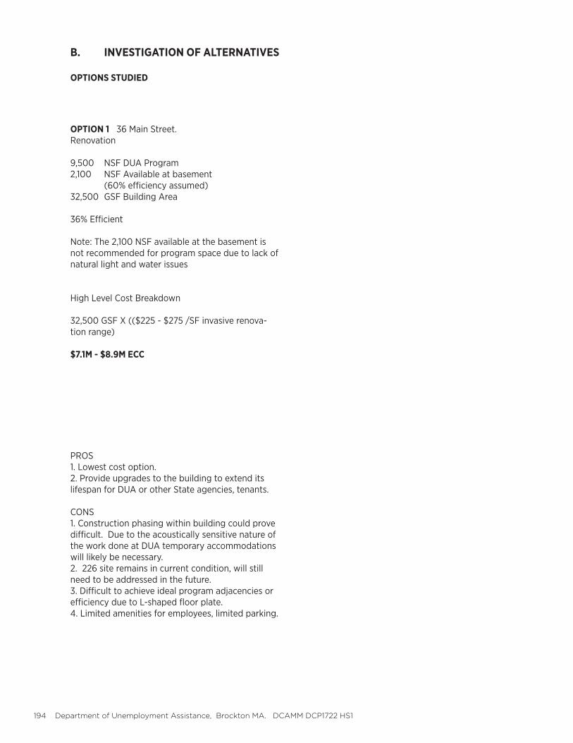
194 Department of Unemployment Assistance, Brockton MA. DCAMM DCP1722 HS1
OPTION 1 36 Main Street. Renovation
9,500 NSF DUA Program2,100 NSF Available at basement (60% efficiency assumed)32,500 GSF Building Area
36% Efficient
Note: The 2,100 NSF available at the basement is not recommended for program space due to lack of natural light and water issues
High Level Cost Breakdown
32,500 GSF X (($225 - $275 /SF invasive renova-tion range)
$7.1M - $8.9M ECC
PROS1. Lowest cost option.2. Provide upgrades to the building to extend its lifespan for DUA or other State agencies, tenants.
CONS1. Construction phasing within building could prove difficult. Due to the acoustically sensitive nature of the work done at DUA temporary accommodations will likely be necessary.2. 226 site remains in current condition, will still need to be addressed in the future.3. Difficult to achieve ideal program adjacencies or efficiency due to L-shaped floor plate.4. Limited amenities for employees, limited parking.
B. INVESTIGATION OF ALTERNATIVES
OPTIONS STUDIED
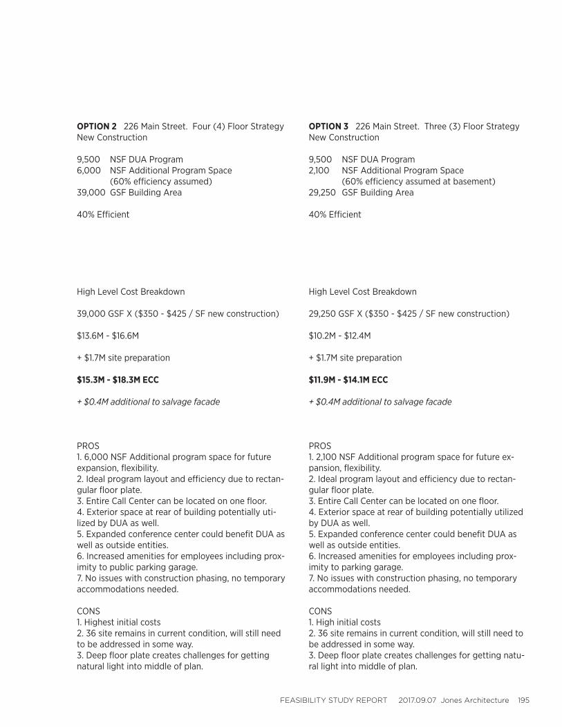
FEASIBILITY STUDY REPORT 2017.09.07 Jones Architecture 195
OPTION 2 226 Main Street. Four (4) Floor StrategyNew Construction
9,500 NSF DUA Program6,000 NSF Additional Program Space (60% efficiency assumed)39,000 GSF Building Area
40% Efficient
High Level Cost Breakdown
39,000 GSF X ($350 - $425 / SF new construction)
$13.6M - $16.6M
+ $1.7M site preparation
$15.3M - $18.3M ECC
+ $0.4M additional to salvage facade
PROS1. 6,000 NSF Additional program space for future expansion, flexibility.2. Ideal program layout and efficiency due to rectan-gular floor plate.3. Entire Call Center can be located on one floor.4. Exterior space at rear of building potentially uti-lized by DUA as well.5. Expanded conference center could benefit DUA as well as outside entities.6. Increased amenities for employees including prox-imity to public parking garage.7. No issues with construction phasing, no temporary accommodations needed.
CONS1. Highest initial costs2. 36 site remains in current condition, will still need to be addressed in some way.3. Deep floor plate creates challenges for getting natural light into middle of plan.
OPTION 3 226 Main Street. Three (3) Floor StrategyNew Construction
9,500 NSF DUA Program2,100 NSF Additional Program Space (60% efficiency assumed at basement)29,250 GSF Building Area
40% Efficient
High Level Cost Breakdown
29,250 GSF X ($350 - $425 / SF new construction)
$10.2M - $12.4M
+ $1.7M site preparation
$11.9M - $14.1M ECC
+ $0.4M additional to salvage facade
PROS1. 2,100 NSF Additional program space for future ex-pansion, flexibility.2. Ideal program layout and efficiency due to rectan-gular floor plate.3. Entire Call Center can be located on one floor.4. Exterior space at rear of building potentially utilized by DUA as well.5. Expanded conference center could benefit DUA as well as outside entities.6. Increased amenities for employees including prox-imity to parking garage.7. No issues with construction phasing, no temporary accommodations needed.
CONS1. High initial costs2. 36 site remains in current condition, will still need to be addressed in some way.3. Deep floor plate creates challenges for getting natu-ral light into middle of plan.
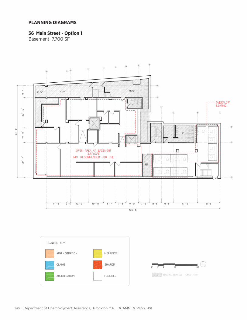
196 Department of Unemployment Assistance, Brockton MA. DCAMM DCP1722 HS1
PLANNING DIAGRAMS
36 Main Street - Option 1Basement 7,700 SF
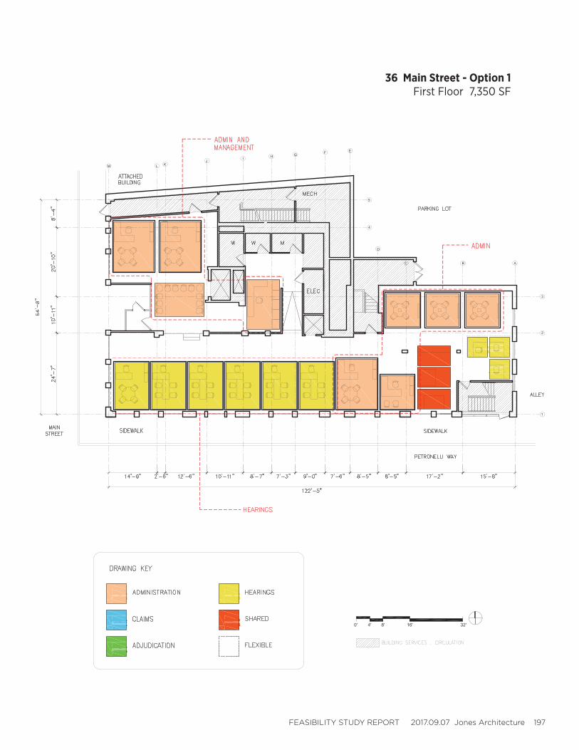
FEASIBILITY STUDY REPORT 2017.09.07 Jones Architecture 197
36 Main Street - Option 1First Floor 7,350 SF
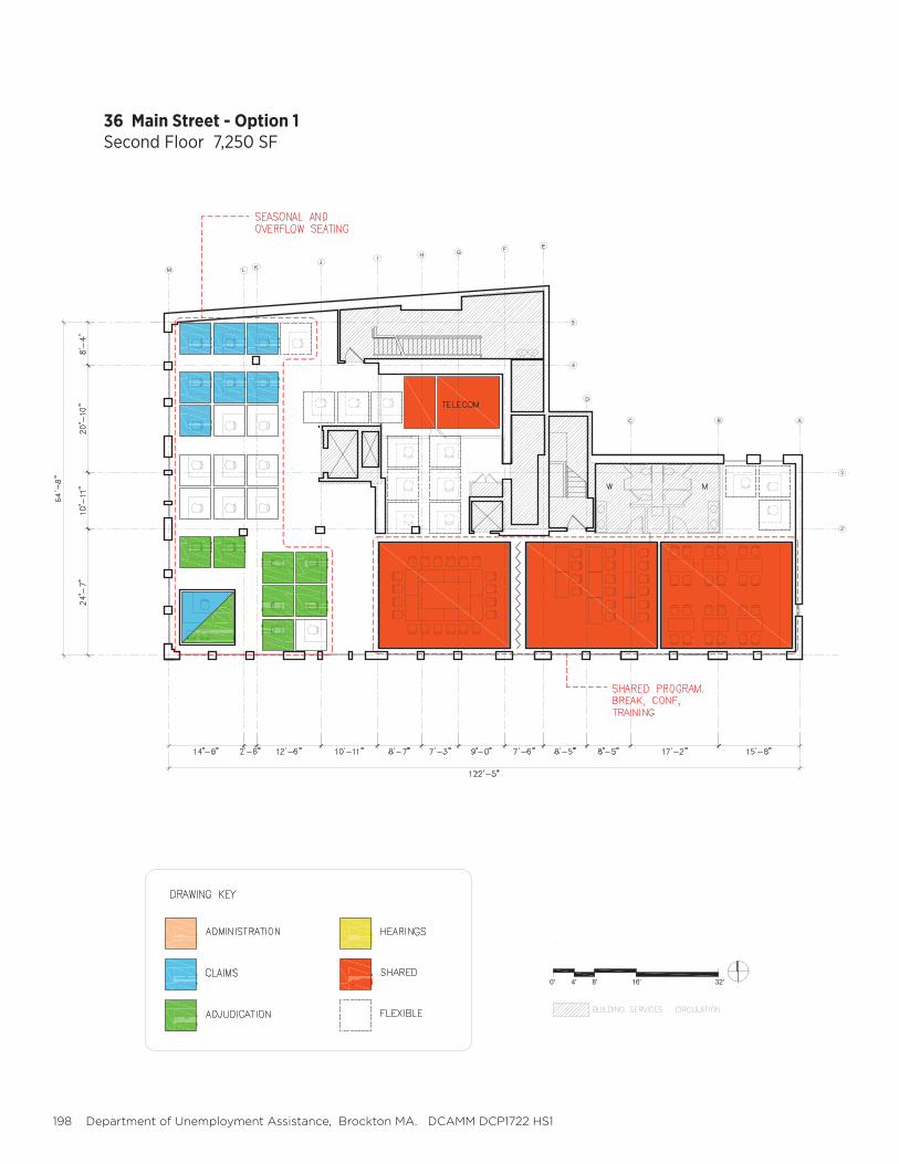
198 Department of Unemployment Assistance, Brockton MA. DCAMM DCP1722 HS1
36 Main Street - Option 1Second Floor 7,250 SF
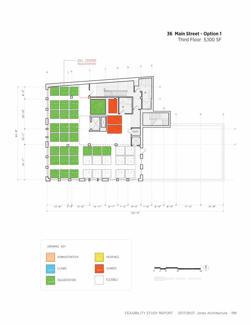
FEASIBILITY STUDY REPORT 2017.09.07 Jones Architecture 199
36 Main Street - Option 1Third Floor 5,100 SF
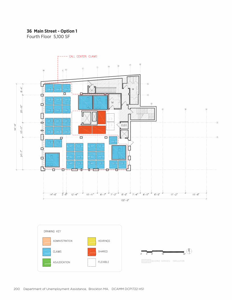
200 Department of Unemployment Assistance, Brockton MA. DCAMM DCP1722 HS1
36 Main Street - Option 1Fourth Floor 5,100 SF

FEASIBILITY STUDY REPORT 2017.09.07 Jones Architecture 201

202 Department of Unemployment Assistance, Brockton MA. DCAMM DCP1722 HS1
PLANNING DIAGRAMS
226 Main Street - Options 2+3Basement 10,200 SF
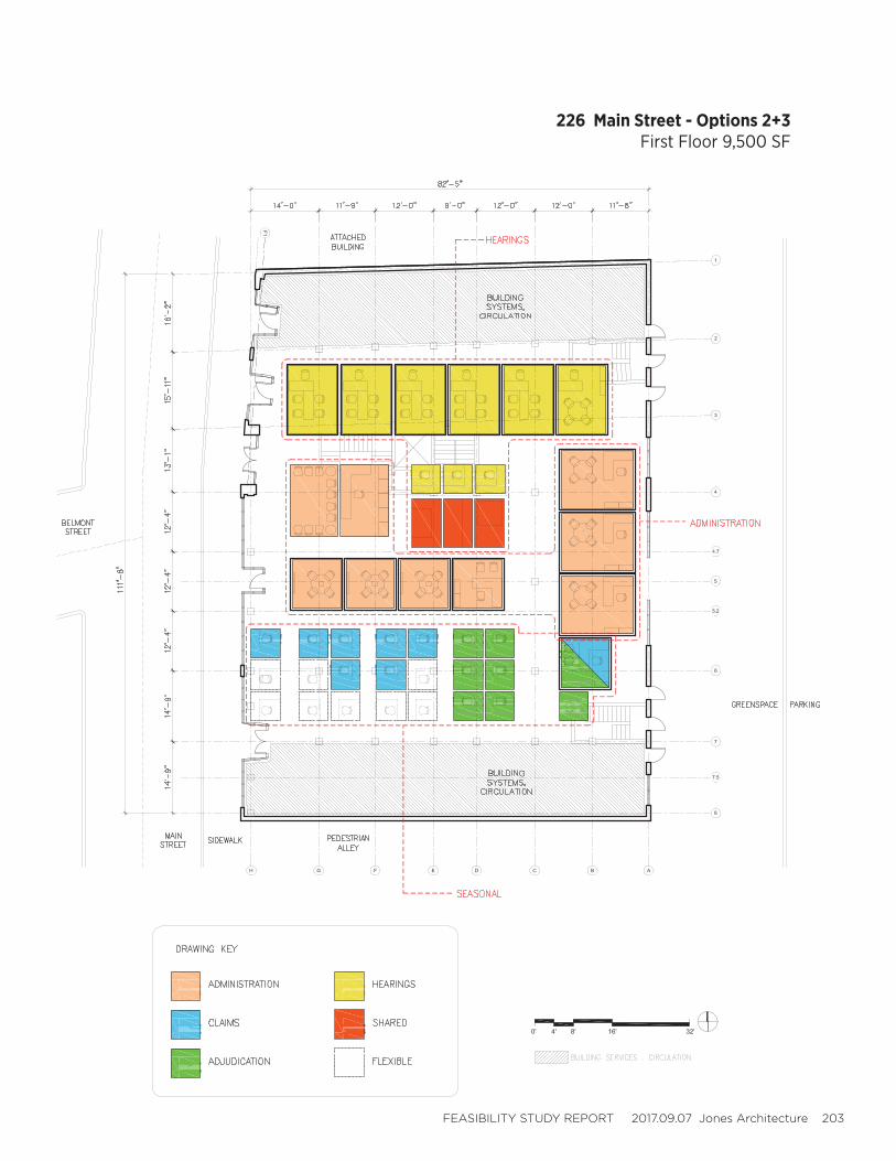
FEASIBILITY STUDY REPORT 2017.09.07 Jones Architecture 203
226 Main Street - Options 2+3First Floor 9,500 SF
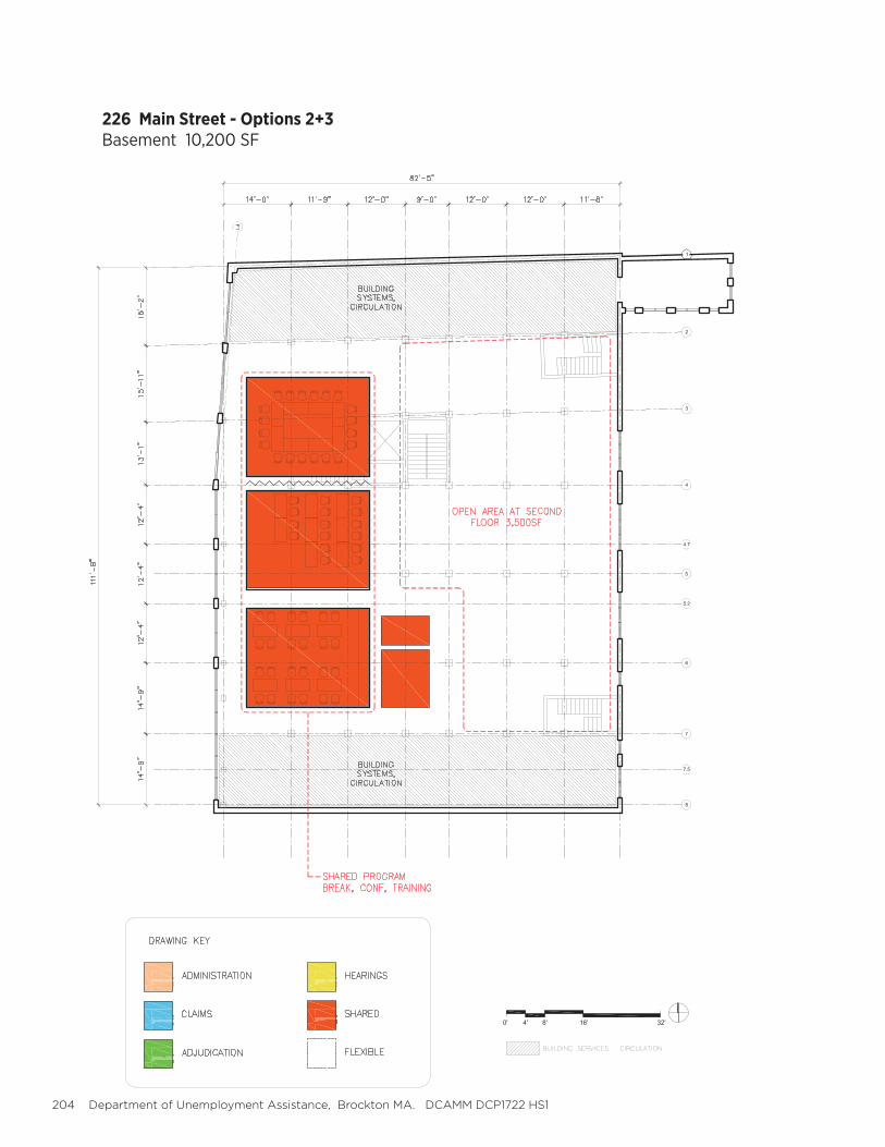
204 Department of Unemployment Assistance, Brockton MA. DCAMM DCP1722 HS1
226 Main Street - Options 2+3Basement 10,200 SF
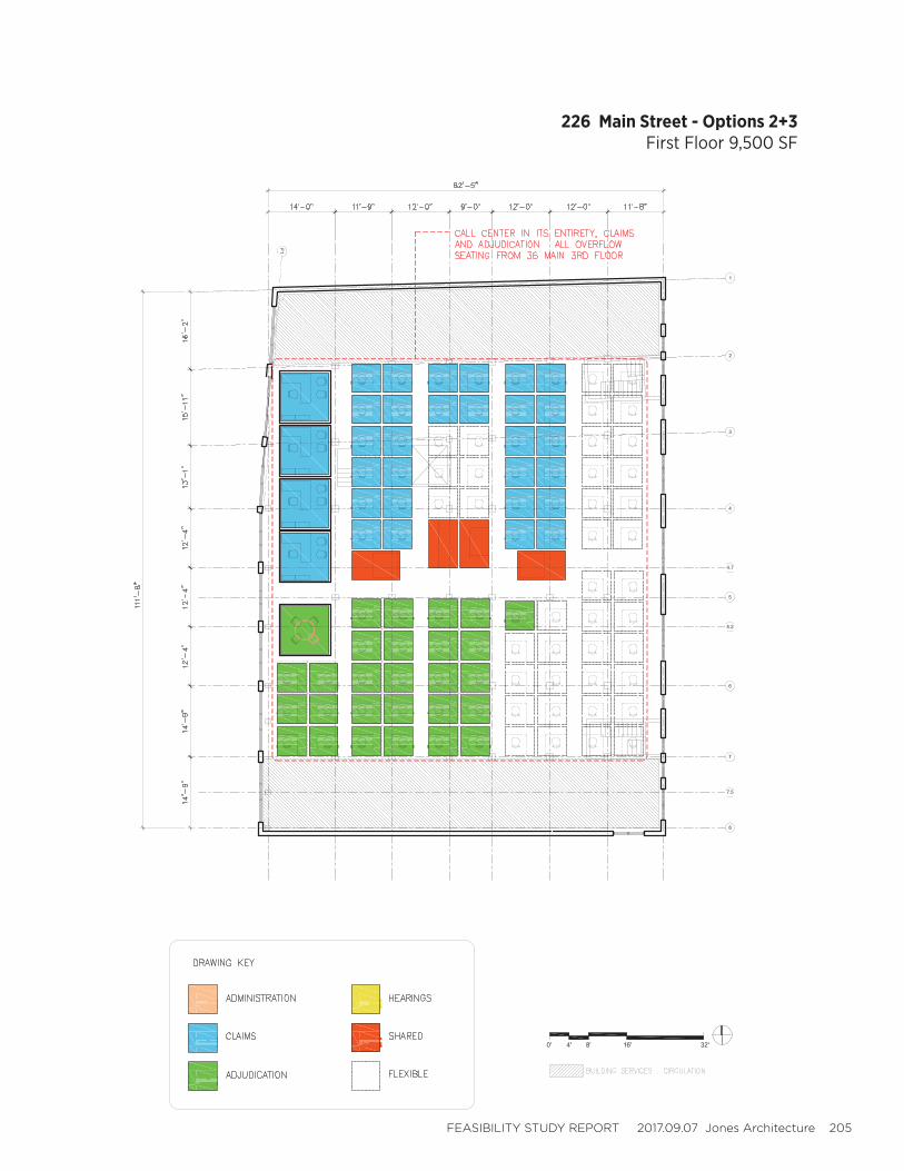
FEASIBILITY STUDY REPORT 2017.09.07 Jones Architecture 205
226 Main Street - Options 2+3First Floor 9,500 SF
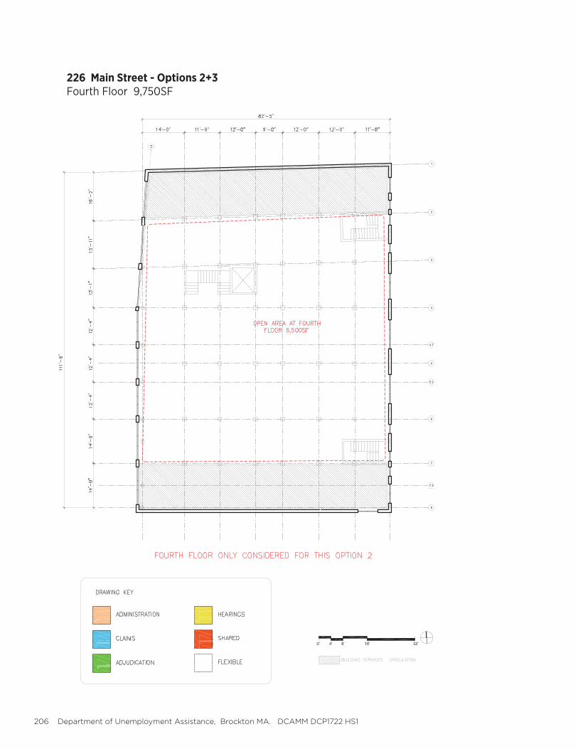
206 Department of Unemployment Assistance, Brockton MA. DCAMM DCP1722 HS1
226 Main Street - Options 2+3Fourth Floor 9,750SF

FEASIBILITY STUDY REPORT 2017.09.07 Jones Architecture 207
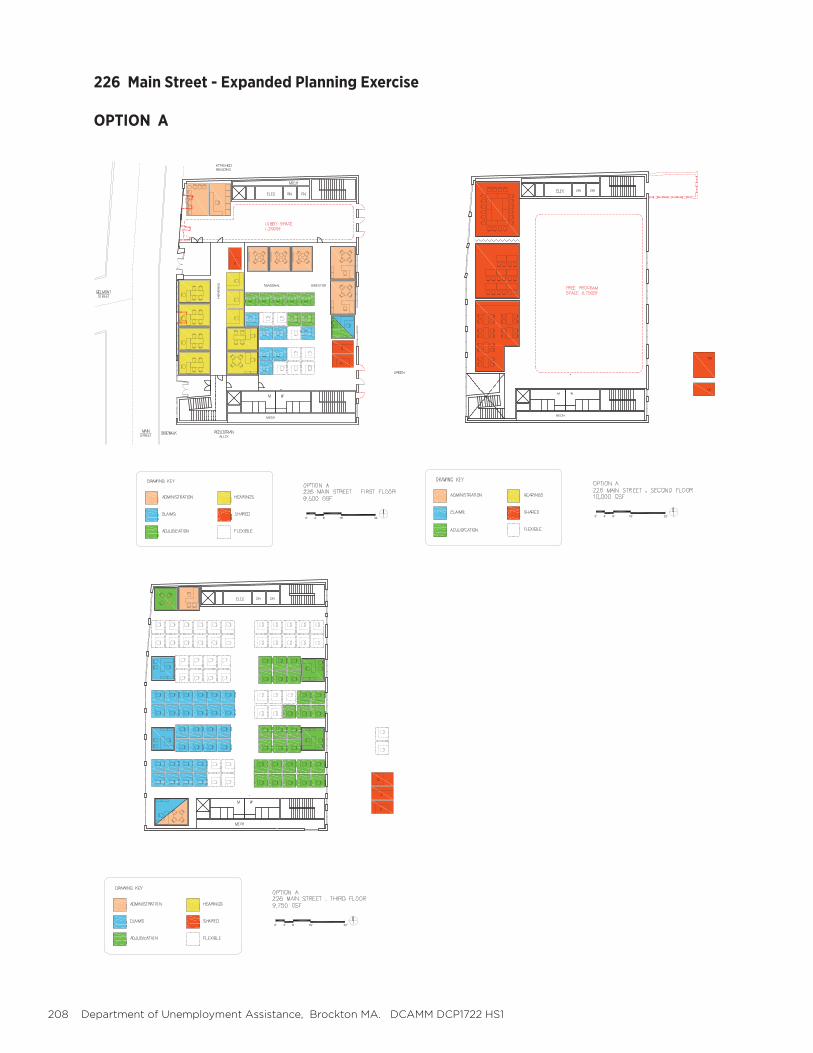
208 Department of Unemployment Assistance, Brockton MA. DCAMM DCP1722 HS1
226 Main Street - Expanded Planning Exercise
OPTION A
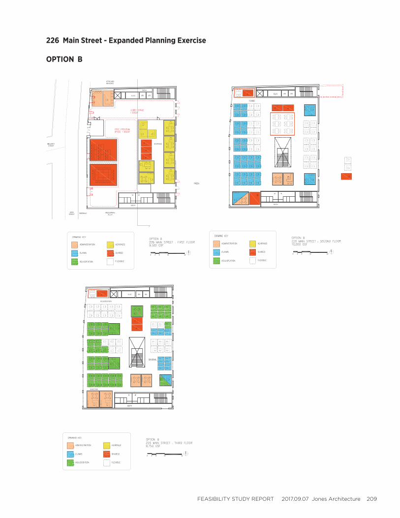
FEASIBILITY STUDY REPORT 2017.09.07 Jones Architecture 209
226 Main Street - Expanded Planning Exercise
OPTION B
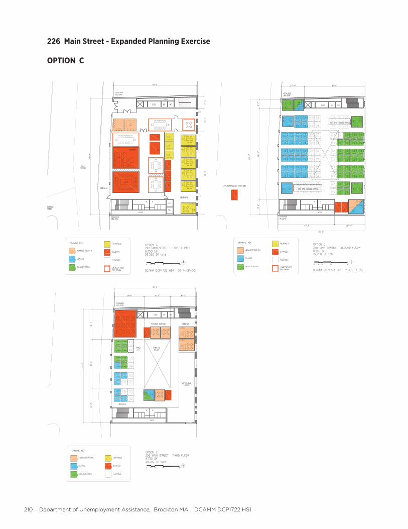
210 Department of Unemployment Assistance, Brockton MA. DCAMM DCP1722 HS1
226 Main Street - Expanded Planning Exercise
OPTION C
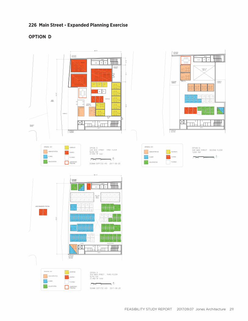
FEASIBILITY STUDY REPORT 2017.09.07 Jones Architecture 211
226 Main Street - Expanded Planning Exercise
OPTION D