Embed Size (px)
Citation preview
1
Student competition 2017 Project description
2017
Develop an autonomous electric car
2
Student competition 2017 Project description
Table of contents
1 System Overview ................................................................................................................................................. 3 2 General competition rules .................................................................................................................................... 3 3 System and track specifications .......................................................................................................................... 4 3.1 General system requirements ........................................................................................................................... 4 3.2.1 Car electronics hardware requirements .......................................................................................................... 4 3.2.2 Client-server protocol requirements ............................................................................................................... 5 3.2.3 GUI requirements:.......................................................................................................................................... 5 3.3 Track specifications .......................................................................................................................................... 5 4 Evaluation ........................................................................................................................................................... 9 4.1 Project Presentation........................................................................................................................................ 17 4.2 Race on the track ............................................................................................................................................ 17 4.2.1 Qualification Round........................................................................................................................................ 17 4.2.2 Autonomous driving ...................................................................................................................................... 19 4.2.3 Manual driving ............................................................................................................................................... 21 ANNEX 1: .................................................................................................................................................................. 22
3
Student competition 2017 Project description
Project goal: Each team shall build one system; the team that achieves the maximum score shall win the competition.
1 System Overview The project consists of 4 parts:
(Power Train) Brushless direct current (BLDC) motor control
(Chassis and Safety) Steering using an electric motor (of any type) or by using an off-the-shelf electric actuator (servo)
(Interior Body & Security) Car environment data transmission
(Infotainment & Connectivity) Client-Server Protocol & Graphical User Interface (GUI) Whenever they are used in the subsequent chapters, the terms below have the following meaning: Car = vehicle which implements all related requirements Smart phone = a device which implements all related requirements System = Car + Smart phone GUI = Graphical User Interface RF = Radio Frequency Control board = electronic circuits which integrate the car logic command (software). From hardware
standpoint, this is the board which integrates the micro controller Inverter = electronic circuit used to command the BLDC motors SW = Software developed or integrated by the team and deployed on the car and Smart phone HW = Electronics hardware
2 General competition rules
Each team must have 3 or 4 members.
Each team shall participate in the competition with one system (replacement parts are allowed).
Each car shall be able to run independently on a predefined track from the Start line to the Stop line
(Race mode – autonomous driving).
Each car shall be able to be driven by a team member using the Smart phone (Race mode – manual
driving).
The car must be driven by at least one BLDC motor
Steering will be ensured either by using an electric motor of any type (might be an off-the-shelf electric
actuator) on a steering shaft/ arm or by different speeds for each traction wheel
While running, the car shall be able to transmit several car parameters to the Smart phone using a client-
server protocol communication system. Detailed requirements are presented in the following chapters.
Each team shall document the hardware, software and mechanical concepts in a design document.
Each team shall send the design documents to the organizers one month before the contest, as
described in the 4th contest phase (Competition rules document). Otherwise, the corresponding points are
lost.
The competition will be organized by the Continental Iasi location. Each year the contest location will be
announced in advance.

4
Student competition 2017 Project description
The team that achieves the highest number of points during the whole event will
win the competition.
The re-flashing/calibration and adjustment of the car are allowed at any time during the entire competition
days.
*Note:
Electrostatic discharge issues due to the building ground (where the final phase of the contest will be
held) should be considered by the participating teams. Protection mechanism for the designed
electronics should be considered.
3 System and track specifications
3.1 General system requirements
R1: Each car shall be able to run in 2 modes: Race mode – autonomous driving and Race mode –
manual driving, on a predefined race track from the START line to the STOP line.
Remark: in Race mode – autonomous driving no external human intervention on the car is allowed during
the laps on the track, except for the Start/Stop command which is permitted.
R2. The traction shall be realized with at least one BLDC motor.
Remarks:
- for further details regarding the motors, see Annex 1;
- the number of car wheels will be defined by each team. R3: Each car shall be powered by batteries and these batteries must be carried by the car.
R4: Each car shall communicate wireless with the Smart phone.
R5: Each System shall include one GUI, which shall run on the Smart phone and shall display the information
exchanged by the car and the Smart phone.
3.2.1 Car electronics hardware requirements
R6: The traction motors must be driven by inverter/inverters (bought from the market or manufactured by the
teams). See the tables from the evaluation criteria chapter.
R7: The control board can be manufactured by the team or a development kit can be used.
Remark: The electronic circuits designed by the team are preferred. See the tables from the evaluation
criteria chapter.
R8: For each car, steering must be ensured either by using an electric motor of any type (or an off-the-shelf
electric actuator) on a steering shaft/ arm or by using motors connected to the traction wheels
R9: If the steering is ensured using the motors connected to the traction wheels, the steering must be
realized based on the speed control of the BLDC motors.
R10: One stall protection shall be implemented for wheels blocked more than 500 ms.
Remark: Be aware that the protection will be tested during the evaluation.
R11: The braking shall use BLDC motors control functions only, no additional mechanical brakes are
allowed.
5
Student competition 2017 Project description
3.2.2 Client-server protocol requirements
R12: Each system shall implement one communication protocol of the client-server type.
R13: The communication protocol support must be wireless.
R14: The communication protocol and the communication type must be detailed in the design document.
R15: In Race mode - autonomous driving (see R1) the car must only receive the START command from
the Smart phone. However, the STOP command given by the team from the Smart phone is allowed only in
case of emergency.
R16: In Race mode - manual driving (see R1), the team will drive the car giving commands from the Smart phone.
3.2.3 GUI requirements: R17: The system must include one GUI to display the information received from the car.
Remark: The GUI shall be displayed on the Smart phone and it shall be user friendly.
R18: The car status displayed on the GUI shall not be older than 5 seconds.
R19: The GUI shall implement three working modes: Test mode, Race mode - autonomous driving and
Race mode - manual driving.
Remark: The test mode will be used only during the design evaluation. Both Race modes will be used during
the races on the track.
R20: In Race mode – autonomous driving, the Smart phone must be able to send only the START
command. The STOP command to the car will be used for emergency situations.
R21: The GUI must display the following information received from the car, in all modes:
- the time elapsed from the START moment. The timer shall stop when the car reaches the STOP line;
- the battery level;
- the car speed;
- the distance travelled by the car from the start point;
- the Left/Right traction wheels status – moving forward/backward or stopped.
Remark: In the Test mode, all the car functional requirements must be available and testable.
3.3 Track specifications
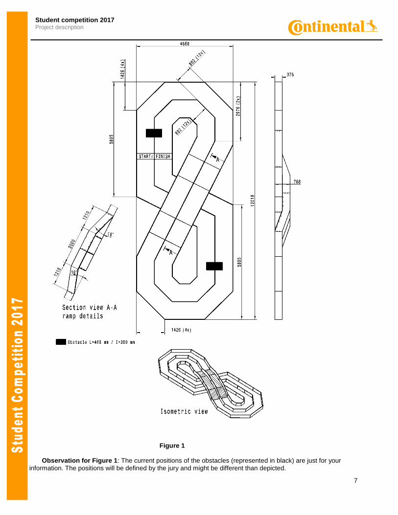
T1: The track shape and its dimensions are presented in Figure 1.
Remark: The participants shall consider a tolerance of 10% between the drawing and the real track
dimensions.
T2: The track running surface is made of thermoplastic material (PES): SIOEN B7119/ color code 1687.
T3: The side walls are made of a dense material (PAL wood) and will have a height between 250 and 380
millimeters. The material color is flat black. Commercial reference is EGGER code U999, finishing ST2, and
thickness 18 mm.
T4: The Start line is marked on the race track by a drawn line.
T5: The Stop line is marked on the race track by a metallic bumper (steel bar).
Remark: The bumper dimensions are: length = track width; height 2 to 5 millimeters; width 10 to 30
millimeters.
T6: On the track, an uphill and a downhill ramp with a slope of 18 degrees and a length of 1.2 m
will be placed.
Remark: Except for the mentioned segment with the ramp, the rest of the track is flat.
T7: Apart from the track curves, two obstacles might be placed on the track. The usage and the placement of
the obstacles will be decided by the organizers during the competition day.
T8: The obstacle position on the track will be the same for all the participants and it will be defined by the
organizers.
6
Student competition 2017 Project description
T9: The distance between Obstacle 1 and Obstacle 2 will be at least 1 meter.
T10: Each obstacle will obstruct approximately 40% of the track width.
Info about obstacles: The role of the obstacles is to partially obstruct the race track width. The obstacles are made of a similar material as the side walls and they will have the same height. The obstacles positions in Figure 1 are just for orientation. During the contest, the position of the obstacle
will be different than depicted in Figure 1, but will remain the same along the entire event.
7
Student competition 2017 Project description
Figure 1 Observation for Figure 1: The current positions of the obstacles (represented in black) are just for your information. The positions will be defined by the jury and might be different than depicted.
8
Student competition 2017 Project description
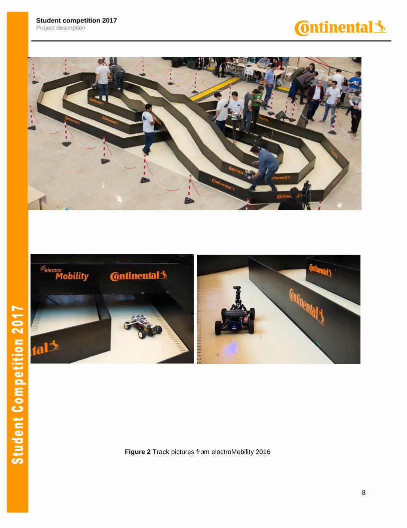
Figure 2 Track pictures from electroMobility 2016
9
Student competition 2017 Project description
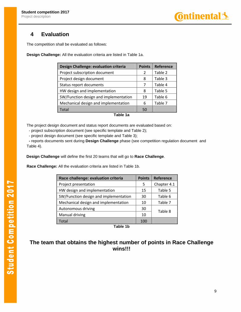
4 Evaluation
The competition shall be evaluated as follows:
Design Challenge: All the evaluation criteria are listed in Table 1a.
Design Challenge: evaluation criteria Points Reference
Project subscription document 2 Table 2
Project design document 8 Table 3
Status report documents 7 Table 4
HW design and implementation 8 Table 5
SW/Function design and implementation 19 Table 6
Mechanical design and implementation 6 Table 7
Total 50 Table 1a
The project design document and status report documents are evaluated based on:
- project subscription document (see specific template and Table 2);
- project design document (see specific template and Table 3);
- reports documents sent during Design Challenge phase (see competition regulation document and
Table 4).
Design Challenge will define the first 20 teams that will go to Race Challenge.
Race Challenge: All the evaluation criteria are listed in Table 1b.
Race challenge: evaluation criteria Points Reference
Project presentation 5 Chapter 4.1
HW design and implementation 15 Table 5
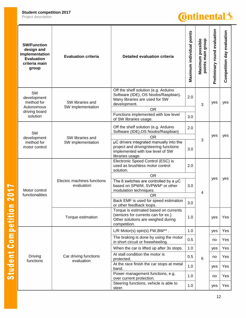
SW/Function design and implementation 30 Table 6
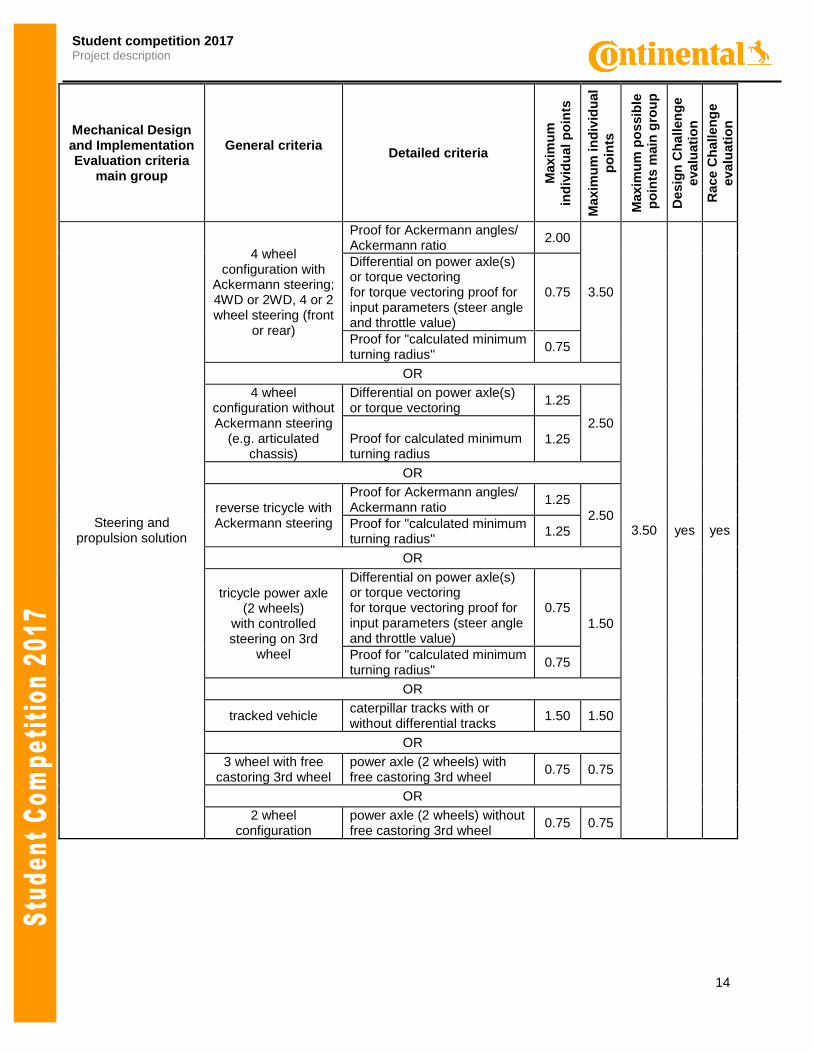
Mechanical design and implementation 10 Table 7
Autonomous driving 30 Table 8
Manual driving 10
Total 100 Table 1b
The team that obtains the highest number of points in Race Challenge wins!!!
10
Student competition 2017 Project description
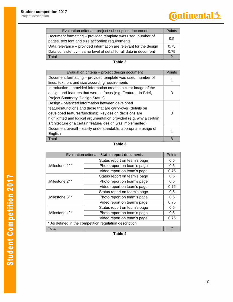
Evaluation criteria – project subscription document Points
Document formatting – provided template was used, number of
pages, text font and size according requirements 0.5
Data relevance – provided information are relevant for the design 0.75
Data consistency – same level of detail for all data in document 0.75
Total 2
Table 2
Evaluation criteria – project design document Points
Document formatting – provided template was used, number of
lines, text font and size according requirements 1
Introduction – provided information creates a clear image of the
design and features that were in focus (e.g. Features-in-Brief,
Project Summary, Design Status)
3
Design - balanced information between developed
features/functions and those that are carry-over (details on
developed features/functions); key design decisions are
highlighted and logical argumentation provided (e.g. why a certain
architecture or a certain feature/ design was implemented)
3
Document overall – easily understandable, appropriate usage of
English 1
Total 8
Table 3
Evaluation criteria – Status report documents Points
„Milestone 1” *
Status report on team’s page 0.5
Photo report on team’s page 0.5
Video report on team’s page 0.75
„Milestone 2” *
Status report on team’s page 0.5
Photo report on team’s page 0.5
Video report on team’s page 0.75
„Milestone 3” *
Status report on team’s page 0.5
Photo report on team’s page 0.5
Video report on team’s page 0.75
„Milestone 4” *
Status report on team’s page 0.5
Photo report on team’s page 0.5
Video report on team’s page 0.75
* As defined in the competition regulation description
Total 7
Table 4
11
Student competition 2017 Project description
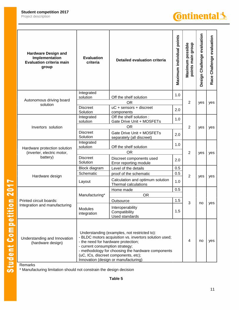
Hardware Design and Implementation
Evaluation criteria main group
Evaluation criteria
Detailed evaluation criteria
Maxim
um
in
div
idu
al
po
ints
Maxim
um
po
ssib
le
po
ints
main
gro
up
Desig
n C
ha
llen
ge e
va
luati
on
Race C
hallen
ge e
valu
ati
on
Autonomous driving board solution
Integrated solution Off the shelf solution
1.0
2 yes yes OR
Discreet Solution
uC + sensors + discreet components
2.0
Invertors solution
Integrated solution
Off the shelf solution : Gate Drive Unit + MOSFETs
1.0
2 yes yes OR
Discreet Solution
Gate Drive Unit + MOSFETs separately (all discreet)
2.0
Hardware protection solution (inverter, electric motor,
battery)
Integrated solution Off the shelf solution
1.0
2 yes yes OR
Discreet Solution
Discreet components used Error reporting module
2.0
Hardware design
Block diagram Level of the details 0.5
2 yes yes Schematic proof of the schematic 0.5
Layout Calculation and optimum solution Thermal calculations
1.0
Printed circuit boards: Integration and manufacturing
Manufacturing*
Home made 0.5
3 no yes
OR
Outsource 1.5
Modules integration
Interoperability Compatibility Used standards
1.5
Understanding and Innovation (hardware design)
Understanding (examples, not restricted to): - BLDC motors acquisition vs. invertors solution used; - the need for hardware protection; - current consumption strategy; - methodology for choosing the hardware components (uC, ICs, discreet components, etc); Innovation (design or manufacturing)
4 no yes
Remarks
* Manufacturing limitation should not constrain the design decision
Table 5
12
Student competition 2017 Project description
SW/Function design and
implementation Evaluation
criteria main group
Evaluation criteria Detailed evaluation criteria
Maxim
um
in
div
idu
al
po
ints
Maxim
um
po
ssib
le
po
ints
main
gro
up
Pre
lim
ina
ry r
ou
nd
eva
lua
tio
n
Co
mp
eti
tio
n d
ay e
valu
ati
on
SW development method for
Autonomous driving board
solution
SW libraries and SW implementation
Off the shelf solution (e.g. Arduino Software (IDE), OS Noobs/Raspbian). Many libraries are used for SW development.
2.0
3 yes yes
OR
Functions implemented with low level of SW libraries usage.
3.0
SW development method for
motor control
SW libraries and SW implementation
Off the shelf solution (e.g. Arduino Software (IDE),OS Noobs/Raspbian)
2.0
3 yes
yes
OR
μC drivers integrated manually into the project and driving/steering functions implemented with low level of SW libraries usage.
3.0
Motor control functionalities
Electric machines functions evaluation
Electronic Speed Control (ESC) is used as brushless motor control solution.
2.0
4
yes
yes
OR
The 6 switches are controlled by a μC based on SPWM, SVPWM* or other modulation techniques.
3.0
OR
Back EMF is used for speed estimation or other feedback loops.
3.0
Torque estimation
Torque is estimated based on currents (sensors for currents can for ex.). Other solutions are weighed during competition.
1.0 yes Yes
Driving functions
Car driving functions evaluation
L/R Motor(s) spin(s) FW,BW** . 1.0
6
yes Yes
The braking is done by using the motor in short circuit or freewheeling.
0.5 no Yes
When the car is lifted up after 3s stops. 1.0 yes Yes
At stall condition the motor is protected.
0.5 no Yes
At the race finish the car stops at metal band.
1.0 yes Yes
Power management functions, e.g. over current protection.
1.0 no Yes
Steering functions, vehicle is able to steer.
1.0 yes Yes
13
Student competition 2017 Project description
SW/Function design and
implementation Evaluation
criteria main group
Evaluation criteria Detailed evaluation criteria
Maxim
um
in
div
idu
al
po
ints
Maxim
um
po
ssib
le
po
ints
main
gro
up
Desig
n C
ha
llen
ge e
va
luati
on
Race C
hallen
ge e
valu
ati
on
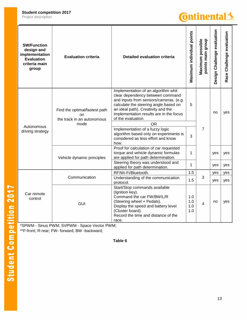
Autonomous driving strategy
Find the optimal/fastest path on
the track in an autonomous mode
Implementation of an algorithm whit clear dependency between command and inputs from sensors/cameras. (e.g. calculate the steering angle based on an ideal path). Creativity and the implementation results are in the focus of the evaluation.
5
7
no
yes
OR
Implementation of a fuzzy logic algorithm based only on experiments is considered as less effort and know how.
3
Vehicle dynamic principles
Proof for calculation of car requested torque and vehicle dynamic formulas are applied for path determination.
1 yes yes
Steering theory was understood and applied for path determination.
1 yes yes
Car remote control
Communication RF/Wi-Fi/Bluetooth. 1.5
3
yes yes
Understanding of the communication protocol.
1.5 yes yes
GUI
Start/Stop commands available (Ignition key). Command the car FW/BW/L/R (Steering wheel + Pedals). Display the speed and battery level (Cluster board). Record the time and distance of the race.
1.0 1.0 1.0 1.0
4 no yes
*SPWM - Sinus PWM; SVPWM - Space Vector PWM;
**F-front; R-rear; FW- forward; BW -backward;
Table 6
14
Student competition 2017 Project description
Mechanical Design and Implementation Evaluation criteria
main group
General criteria
Detailed criteria
Maxim
um
ind
ivid
ual p
oin
ts
Maxim
um
in
div
idu
al
po
ints
Maxim
um
po
ssib
le
po
ints
main
gro
up
Desig
n C
ha
llen
ge
evalu
ati
on
Race C
hallen
ge
evalu
ati
on
Steering and propulsion solution
4 wheel configuration with
Ackermann steering; 4WD or 2WD, 4 or 2 wheel steering (front
or rear)
Proof for Ackermann angles/ Ackermann ratio
2.00
3.50
3.50 yes yes
Differential on power axle(s) or torque vectoring for torque vectoring proof for input parameters (steer angle and throttle value)
0.75
Proof for "calculated minimum turning radius"
0.75
OR
4 wheel configuration without Ackermann steering
(e.g. articulated chassis)
Differential on power axle(s) or torque vectoring
1.25
2.50 Proof for calculated minimum turning radius
1.25
OR
reverse tricycle with Ackermann steering
Proof for Ackermann angles/ Ackermann ratio
1.25
2.50 Proof for "calculated minimum turning radius"
1.25
OR
tricycle power axle (2 wheels)
with controlled steering on 3rd
wheel
Differential on power axle(s) or torque vectoring for torque vectoring proof for input parameters (steer angle and throttle value)
0.75
1.50
Proof for "calculated minimum turning radius"
0.75
OR
tracked vehicle caterpillar tracks with or without differential tracks
1.50 1.50
OR
3 wheel with free castoring 3rd wheel
power axle (2 wheels) with free castoring 3rd wheel
0.75 0.75
OR
2 wheel configuration
power axle (2 wheels) without free castoring 3rd wheel
0.75 0.75
15
Student competition 2017 Project description
Mechanical Design and Implementation Evaluation criteria
main group
General criteria
Detailed criteria
Maxim
um
ind
ivid
ual p
oin
ts
Maxim
um
in
div
idu
al
po
ints
Maxim
um
po
ssib
le
po
ints
main
gro
up
Desig
n C
ha
llen
ge e
va
luati
on
Race C
hallen
ge e
valu
ati
on
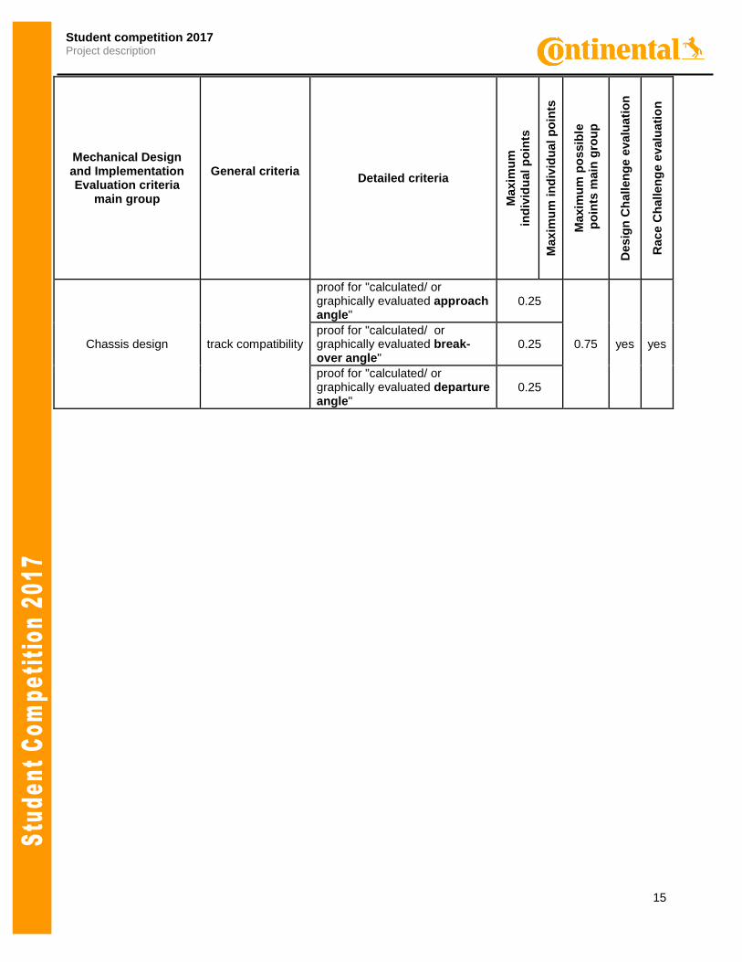
Chassis design track compatibility
proof for "calculated/ or graphically evaluated approach angle"
0.25
0.75 yes yes proof for "calculated/ or graphically evaluated break-over angle"
0.25
proof for "calculated/ or graphically evaluated departure angle"
0.25
16
Student competition 2017 Project description
Mechanical Design and
Implementation Evaluation criteria
main group
General criteria
Detailed criteria
Maxim
um
ind
ivid
ual p
oin
ts
Maxim
um
in
div
idu
al
po
ints
Maxim
um
po
ssib
le
po
ints
main
gro
up
Desig
n C
ha
llen
ge
evalu
ati
on
Race C
hallen
ge e
valu
ati
on
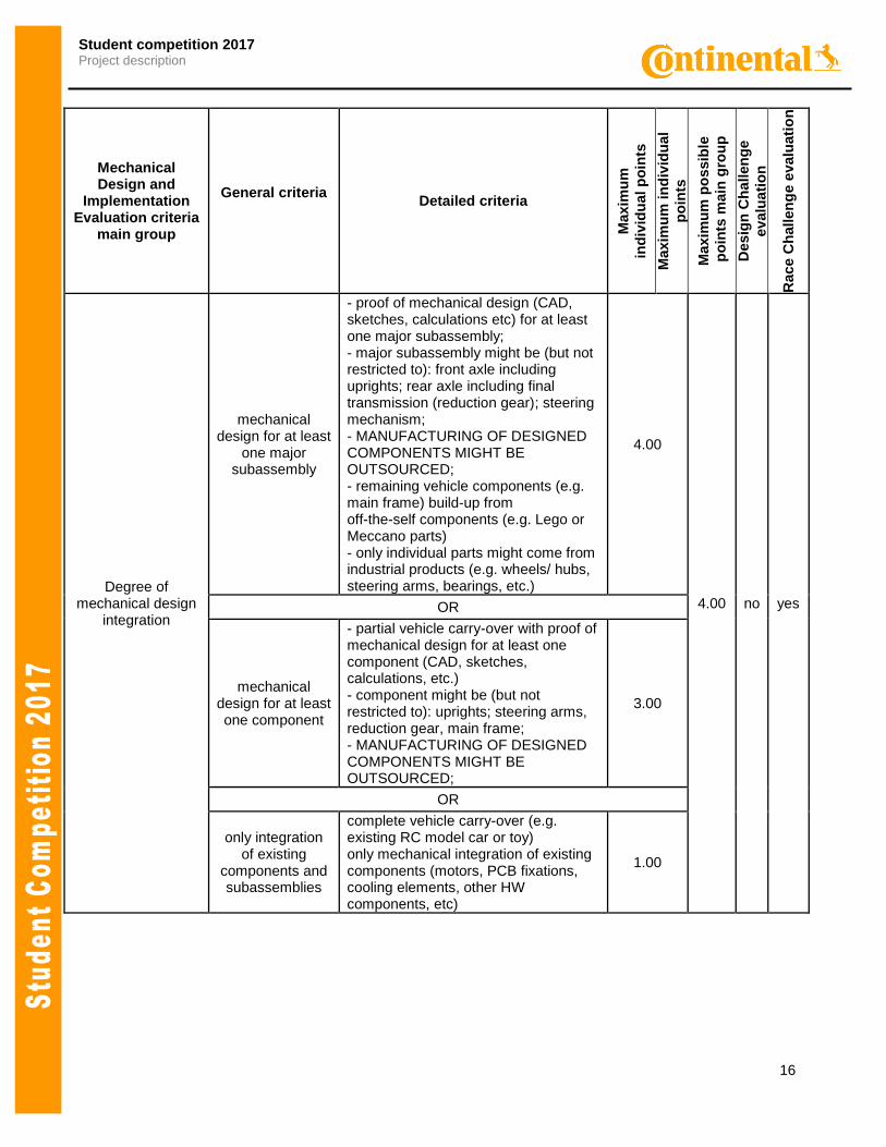
Degree of mechanical design
integration
mechanical design for at least
one major subassembly
- proof of mechanical design (CAD, sketches, calculations etc) for at least one major subassembly; - major subassembly might be (but not restricted to): front axle including uprights; rear axle including final transmission (reduction gear); steering mechanism; - MANUFACTURING OF DESIGNED COMPONENTS MIGHT BE OUTSOURCED; - remaining vehicle components (e.g. main frame) build-up from off-the-self components (e.g. Lego or Meccano parts) - only individual parts might come from industrial products (e.g. wheels/ hubs, steering arms, bearings, etc.)
4.00
4.00 no yes OR
mechanical design for at least one component
- partial vehicle carry-over with proof of mechanical design for at least one component (CAD, sketches, calculations, etc.) - component might be (but not restricted to): uprights; steering arms, reduction gear, main frame; - MANUFACTURING OF DESIGNED COMPONENTS MIGHT BE OUTSOURCED;
3.00
OR
only integration of existing
components and subassemblies
complete vehicle carry-over (e.g. existing RC model car or toy) only mechanical integration of existing components (motors, PCB fixations, cooling elements, other HW components, etc)
1.00
17
Student competition 2017 Project description
Mechanical Design and Implementation Evaluation criteria
main group
General criteria
Detailed criteria
Maxim
um
ind
ivid
ual p
oin
ts
Maxim
um
in
div
idu
al
po
ints
Maxim
um
po
ssib
le
po
ints
main
gro
up
Desig
n C
ha
llen
ge
evalu
ati
on
Race C
hallen
ge
evalu
ati
on
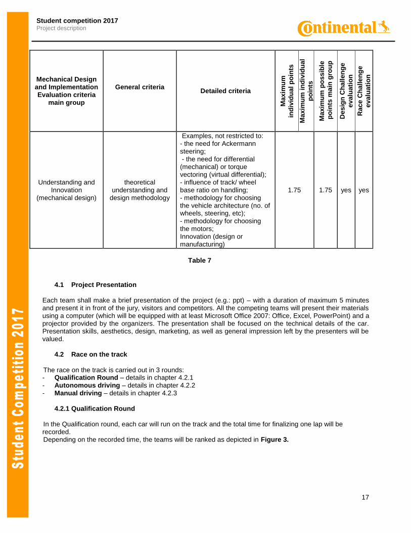
Understanding and Innovation
(mechanical design)
theoretical understanding and
design methodology
Examples, not restricted to: - the need for Ackermann steering; - the need for differential (mechanical) or torque vectoring (virtual differential); - influence of track/ wheel base ratio on handling; - methodology for choosing the vehicle architecture (no. of wheels, steering, etc); - methodology for choosing the motors; Innovation (design or manufacturing)
1.75 1.75 yes yes
Table 7
4.1 Project Presentation
Each team shall make a brief presentation of the project (e.g.: ppt) – with a duration of maximum 5 minutes and present it in front of the jury, visitors and competitors. All the competing teams will present their materials using a computer (which will be equipped with at least Microsoft Office 2007: Office, Excel, PowerPoint) and a projector provided by the organizers. The presentation shall be focused on the technical details of the car. Presentation skills, aesthetics, design, marketing, as well as general impression left by the presenters will be valued.
4.2 Race on the track
The race on the track is carried out in 3 rounds:
- Qualification Round – details in chapter 4.2.1 - Autonomous driving – details in chapter 4.2.2 - Manual driving – details in chapter 4.2.3
4.2.1 Qualification Round
In the Qualification round, each car will run on the track and the total time for finalizing one lap will be
recorded. Depending on the recorded time, the teams will be ranked as depicted in Figure 3.
18
Student competition 2017 Project description
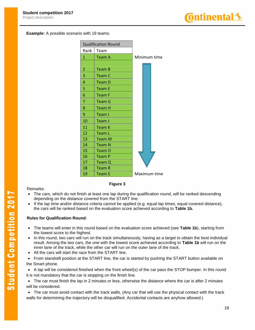
Example: A possible scenario with 19 teams.
Qualification Round Rank Team 1 Team A Minimum time
2 Team B
3 Team C 4 Team D 5 Team E 6 Team F 7 Team G 8 Team H 9 Team I 10 Team J 11 Team K 12 Team L 13 Team M 14 Team N 15 Team O 16 Team P 17 Team Q 18 Team R 19 Team S Maximum time
Figure 3 Remarks:
The cars, which do not finish at least one lap during the qualification round, will be ranked descending depending on the distance covered from the START line.
If the lap time and/or distance criteria cannot be applied (e.g. equal lap times, equal covered distance), the cars will be ranked based on the evaluation score achieved according to Table 1b.
Rules for Qualification Round:
The teams will enter in this round based on the evaluation score achieved (see Table 1b), starting from the lowest score to the highest.
In this round, two cars will run on the track simultaneously, having as a target to obtain the best individual result. Among the two cars, the one with the lowest score achieved according to Table 1b will run on the inner lane of the track, while the other car will run on the outer lane of the track.
All the cars will start the race from the START line.
From standstill position at the START line, the car is started by pushing the START button available on
the Smart phone.
A lap will be considered finished when the front wheel(s) of the car pass the STOP bumper. In this round
it is not mandatory that the car is stopping on the finish line.
The car must finish the lap in 2 minutes or less, otherwise the distance where the car is after 2 minutes
will be considered.
The car must avoid contact with the track walls. (Any car that will use the physical contact with the track
walls for determining the trajectory will be disqualified. Accidental contacts are anyhow allowed.)
19
Student competition 2017 Project description
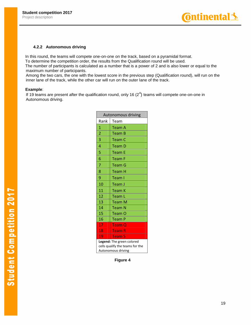
4.2.2 Autonomous driving
In this round, the teams will compete one-on-one on the track, based on a pyramidal format. To determine the competition order, the results from the Qualification round will be used. The number of participants is calculated as a number that is a power of 2 and is also lower or equal to the
maximum number of participants. Among the two cars, the one with the lowest score in the previous step (Qualification round), will run on the
inner lane of the track, while the other car will run on the outer lane of the track. Example:
If 19 teams are present after the qualification round, only 16 (24) teams will compete one-on-one in
Autonomous driving.
Autonomous driving
Rank Team
1 Team A
2 Team B
3 Team C
4 Team D
5 Team E
6 Team F
7 Team G
8 Team H
9 Team I
10 Team J
11 Team K
12 Team L
13 Team M
14 Team N
15 Team O
16 Team P
17 Team Q
18 Team R
19 Team S Legend: The green colored cells qualify the teams for the Autonomous driving
Figure 4
20
Student competition 2017 Project description
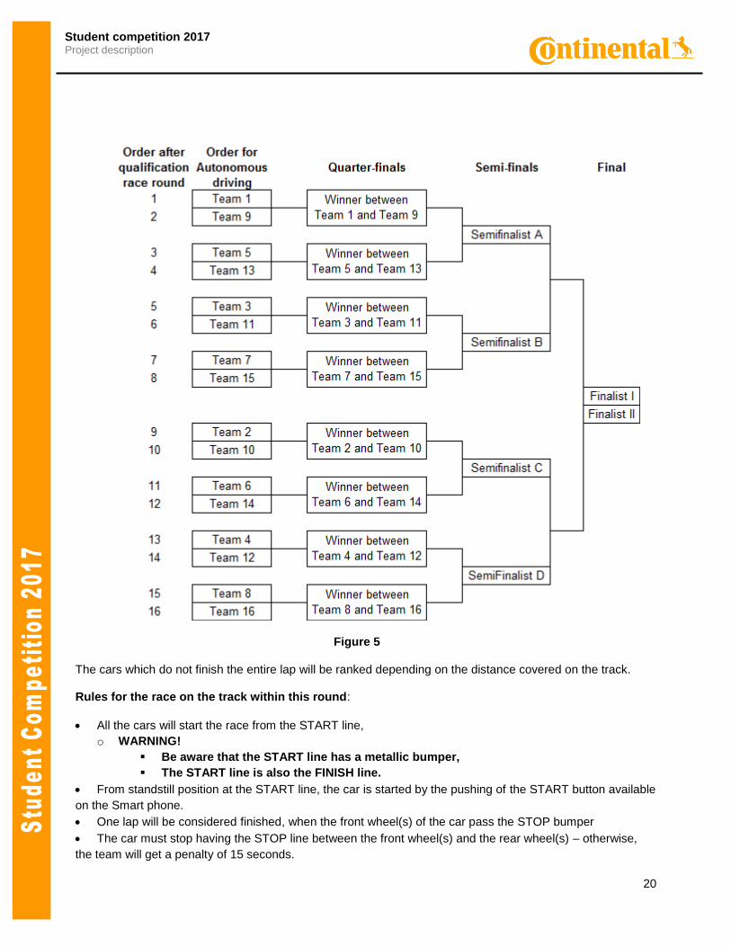
Figure 5
The cars which do not finish the entire lap will be ranked depending on the distance covered on the track.
Rules for the race on the track within this round:
All the cars will start the race from the START line,
o WARNING!
Be aware that the START line has a metallic bumper,
The START line is also the FINISH line.
From standstill position at the START line, the car is started by the pushing of the START button available
on the Smart phone.
One lap will be considered finished, when the front wheel(s) of the car pass the STOP bumper
The car must stop having the STOP line between the front wheel(s) and the rear wheel(s) – otherwise,
the team will get a penalty of 15 seconds.
21
Student competition 2017 Project description
The car must finish the lap in 2 minutes or less, otherwise the distance where the car is after 2 minutes
will be considered to calculate the points.
The race order is done based on qualification round.
In this round, two cars will run on the track simultaneously, having as a target to obtain the best individual
result. Among the two cars, the one with the lowest rank in qualification round will run on the inner lane of the
track, while the other car will run on the outer lane of the track.
The car must avoid contact with the track walls. (Any car that will use the physical contact with the track
walls for determining the trajectory will be disqualified. Accidental contacts are anyhow allowed.)
Remark: The STOP condition must be reached by using the track information (distance, speed, acceleration, STOP metal bumper etc).
4.2.3 Manual driving
In this round, the teams will compete one-on-one on the track. The entering criteria in this round are also the rank obtained in the previous step (Qualification round). The cars will be driven by the team members from their Smart phones (only). The race order is the same as in Autonomous driving. Rules for the race on the track within this round:
In this round, two cars will run on the track simultaneously, having as a target to obtain the best individual
result. Among the two cars, the one with the lowest rank in qualification round will run on the inner lane of the
track, while the other car will run on the outer lane of the track.
All the cars will start the race from the START line.
From standstill position at the START line, the car is started by the pushing of the START button available
on the Smart phone.
A lap will be considered finished when the front wheel(s) of the car pass the STOP bumper. In this round
it is not mandatory that the car is stopping on the finish line.
The car must finish the lap in 2 minutes or less, otherwise the distance where the car is after 2 minutes
will be considered to calculate the points.
After these rounds, the points will be distributed according to Table 8.
Results after the one-on-one races
Place Number of points Number of points
Autonomous driving Manual driving
Winner of the race 30 10
Second place 24 8
Places 3-4 21 7
Places 5-8 15 5
Places 9-16 12 4
Places 17-32 9 3
. Table 8
The final score for the race rounds will be calculated by adding the number of points obtained in both phases: Autonomous driving and Manual driving.
22
Student competition 2017 Project description
ANNEX 1:
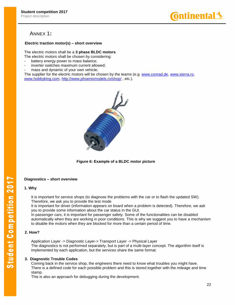
Electric traction motor(s) – short overview
The electric motors shall be a 3 phase BLDC motors. The electric motors shall be chosen by considering: - battery energy power to mass balance; - inverter switches maximum current allowed; - mass and dynamic of your own vehicle; The supplier for the electric motors will be chosen by the teams (e.g. www.conrad.de, www.sierra.ro, www.hobbyking.com, http://www.phoenixmodels.ro/shop/ , etc.).
Figure 6: Example of a BLDC motor picture
Diagnostics – short overview
1. Why
It is important for service shops (to diagnose the problems with the car or to flash the updated SW). Therefore, we ask you to provide the test mode It is important for driver (information appears on board when a problem is detected). Therefore, we ask you to provide some information about the car status in the GUI. In passenger cars, it is important for passenger safety. Some of the functionalities can be disabled automatically when they are working in poor conditions. This is why we suggest you to have a mechanism to disable the motors when they are blocked for more than a certain period of time.
2. How? Application Layer -> Diagnostic Layer-> Transport Layer -> Physical Layer
The diagnostics is not performed separately, but is part of a multi-layer concept. The algorithm itself is implemented by each application, but the services share the same format.
3. Diagnostic Trouble Codes Coming back in the service shop, the engineers there need to know what troubles you might have.
There is a defined code for each possible problem and this is stored together with the mileage and time stamp. This is also an approach for debugging during the development.