Embed Size (px)
Citation preview

This manual has been developed to outline the process for qualifying a laboratory to perform testing for projects for the Nebraska Department of Roads or have funding or oversite by theFHWA and to provide a system to insure compliance with NDOR testing laboratory standards.Any laboratory not meeting the requirements set forth in this document is not qualified toperform laboratory services on such projects.
The following manual consists of procedures for the calibrationof laboratory equipment along
Aggregate, Bituminous, PCC, Soils, and the associated laboratory equipment. The testers mustbe certified and perform tests as outlined in NDOR's QAP manual.
The qulification procedures will require either a certificate, verification, or calibration for thespecified testing equipment.
Certificate: A certificate of calibration are those received with the purchase of the standard test equipment that is used to calibrate or verify other equipment in the laboratory, or those received when an outside contractor calibrates testing equipment, or those received from the manufacturer when new equipment is purchased.
Verification: A verification is performed by the laboratory and its technicians and is then reveiwed by the NDOR Laboratory Representatives at regular intervals as identified in the procedures. Complete calibration and verification records shall be kept on file at all times.
Calibration: The subject laboratory equipment shall be calibrated by the NDOR laboratory representative.
The procedure for the qualification process is as follows:
1) The consultant/laboratory receives copy of this manual prior to NDOR's review. 2) The consultant/laboratory goes through each procedure for each equipment and test and assembles the proper documentation as defined in each procedure in this manual.
3) When all documentation is complete, contact the assistant Materials and Research Engineer to schedule the qualification review at:
1 of 2 Pages
INTRODUCTION
2017 LABORATORY QUALIFICATION MANUAL
with calibration worksheets (where required) as pertaining to the following disciplines.

Nebraska Department of RoadsRobert C. Rea, Assistant Materials and Research Engineer1400 Highway 2P. O. Box 94759Lincoln, NE 68509-4759 [email protected] (402) 479-3839Cell (402) 326-9934Fax (402) 479-3975
4) The qualification review will take approximately 2 days, in which the laboratory must have their Laboratory Contact working directly with the NDOR lab qualification review personnel throughout the review.
Certificates of calibration and the verification documentation must be performed at theintervals specified by the procedures. Completed calibration and verification records shall bekept on file for review at any time.
If the laboratory equipment does not meet the qualification requirements, the NDORLaboratory Representatives shall notify the Laboratory Contact. After notification, thelaboratory equipment shall be corrected, replaced, or taken out of service. Documentation ofthe correction of the deficiencies shall be submitted to the NDOR Laboratory Representativewithin 30 days of notification, and the qualification process will resume.
It is the laboratories sole responsibility to maintain the equipment according to the proceduresset forth in this manual and by any means they deem necessary over and above these procedures.
This procedure is for the sole purpose of defining a process to verify that a laboratory isqualified and is acceptable to perform testing for NDOR Projects operating under the umbrellaof NDOR's approved testing laboratories standards for FHWA, State and Federally FundedProjects. This qualification is for the purposes stated previously and is provided (as is) and anyexpress or implied warranties including, but not limited to, certifications, verifications, orprocedures are disclaimed. In no event shall NDOR, FHWA, or any entities be liable to theconsultant/laboratory or to any third party for any direct, indirect, incidental, consequential,special, or exemplary damages or lost profit resulting from any use or misuse of this data,incorrect data or any data produced as a product of this manual.

CONCRETE ASPHALT AGGREGATE SOILS
PERSONNEL INFORMATIONPOSITION FAX
SOILS5 (YR) OTHER ACI (5 YR) I.A. (1 YR) PLANT OTHER
REPORTS RECEIVED DATE -
REMARKS
EQUIPMENT CALIBRATED BY -TYPE OF LABORATORY ACCREDITATION
NAME
CERTIFIED LABORATORY TECHNICIANSAGGREGATES ASPHALT CONCRETE
E-MAIL ADDRESS
Materials Certified To TestPHONE NUMBERS
NAME LAB PHONE CELL PHONE
City, State, Zip
*Contact PersonE-MAIL Address
2017 LABORATORY EVALUATION CHECKLIST LABORATORY
Mailing Address

All calibration and verification records shall be kept in the office of the Commercial Laboratory Supervisor.
Procedure No. 63
Procedure No. 61
Procedure No. 11
Outside Contractor
Procedure No. 28
Outside Contractor
Procedure No. 38
Procedure No. 37
Equipment Calibration and Verification Information
Equipment - Requirement - Test Method Procedure Reference
Procedure No. 35
Sample SplitterAASHTO T 248
Verify
AGGREGATE EQUIPMENTStand, Funnel and Cylindrical MeasureAASHTO T 304
Verify
Verify
Procedure No. 9
Procedure No. 60
BITUMINOUS EQUIPMENTBreaking Heads - Critical DimensionsAASHTO T 245
Verify
Conical Molds and Tampers - Critical DimensionsAASHTO T 84
Verify
Manual and Mechanical CompactorsAASHTO T 245
Compression Testing Machines
Volumetric Air MeterVerify Procedure No. 65
AASHTO T 245Certificate
Ignition OvenAASHTO T 308
CertificateGyratory CompactorAASHTO T 312Gyratory Molds and Ram HeadsAASHTO T 312
Verify
Marshall MoldsAASHTO T 245
Verify
Vacuum SystemCalibrate
Procedure No. 3
Procedure No. 23AASHTO T 209
Certificate
Verify
Procedure No. 36
Procedure No. 62
Procedure No. 26
Bearing Blocks and Retainers - PlanenessASTM C 39Compression Machines
CertificateVerify
Calibrate
PCC EQUIPMENT
VerifyProcedure No. 6
Procedure No. 6A
ASTM C 39Moist Rooms/ Storage Tanks - Temp. & HumidityASTM C 39
Verify
Verify
Unit Weight MeasureCapping Material - Strength Verify
Air MetersASTM C 231
ASTM C 138Verify
ASTM C 173
LABORATORY:LOCATION:

Thermometers Verify
Mechanical Shakers - Sieving Thoroughness VerifySieves - Physical Condition Verify
Verify Procedure No. 18
SOILS EQUIPMENT
Equipment - Requirement - Test MethodCertificate
VerifyCalibrate
Procedure Reference
Calibrate
Mechanical Soil RammersAASHTO T 99 & T 180Molds - Critical Dimensions/ VolumeAASHTO T 99 & T 180Straightedges - Planeness of Edge
Grooving Tools - Critical DimensionsAASHTO T 89
Ovens - Temperature Settings
Verify
VerifyAASHTO T 208, T 216, T 265
MISCELLANEOUS EQUIPMENT
Procedure No. 1
Balances, Scales & Weights (General Purpose)Procedure No. 8
Verify
Verify
Verify
Verify
AASHTO T 208, T 216, T 265, T 296
AASHTO T 99 & T 180
Liquid Limit Devices - Wear and Critical DimensionsAASHTO T 89Manual Hammers - Weight and Critical DimensionsAASHTO T 99 & T 180
Procedure No. 19
Procedure No. 18
Procedure No. 22A
Procedure No. 5 Procedure No. 5A Procedure No. 22
Procedure No. 27Procedure No. 25Procedure No. 64
Procedure No. 2

1. Condition of Laboratory Very good Good Fair Poor
2. Condition of Equipment Very good Good Fair Poor
3. Calibration I.D. Tags on Equipment Yes NoRemarks
4. Calibration Certificates Received Yes NoRemarks
5. Calibration of Equipment is Performed By.Remarks
6. Certified to Test what MaterialAsphalt Concrete Soil Aggregate
7. Received Technicians Testing Certificates Yes No
Remarks
Very good Good Fair PoorRemarks
11. Testing Procedures Reviewed Complete Asphalt Sample Yes NoRemarks
12. Quality Assurance Manual Kept on File Yes No
13. Laboratory AMRL Inspected Yes No
Remarks
2017 EVALUATION OF CONSULTANTS LABORATORYNEBRASKA DEPARTMENT OF ROADS
LABORATORY Date EvaluatedLocation of Lab. Date Procedure ReviewedPhone Number Lab. PersonnelE-Mail AddressFax NumberInspected By Ron Vajgrt
Site Manager
8. Cooperation from Lab. Personnel
9. Lab. Personnel Reviewed(1 Year I.A.)
10. Lab. Personnel Reviewed(5 Year Certificate)
Not Required

Equipment Checked: FUNNEL STAND APPARATUS AND 100 ml CYLINDRICAL
Purpose:This procedure provide instructions for the checking the volume of the cylindrical measure and the critical dimensions of the funnel stand apparatus used in this test method.
Inspection Equipment Required:1. Caliper2. Balance3. Thermometer4. Glass plate and grease
Tolerances:The equipment shall meet the tolerances specified in the test methodAASHTO T 304.
Procedure:The first step is to calibrate the cylindrical measure. Apply a light coat of greaseto the top edge of the dry empty cylinder measure. Weight the measure, grease and glass plate. Fill the measure with deionized water at the temperature of 18to 24° C (64.4 to 75.2° F). Record the temperature of the water. Place the glass plate on the measure, being sure no air bubbles remain. Dry the outside of the measure and weigh the measure with the water and glass plate on top. Calculatethe volume of the measure on the worksheet.
After calibrating the measure, place the measure on the funnel stand apparatusand check the critical dimensions. Check the dimensions with the tolerancesspecified in AASHTO T 304 test procedure.
Verification Interval:12 Months
Report:A copy must be retained in the Testing Facilities files for review.
Procedure for Verifying Funnel Stand Apparatus and100 ml Cylindrical Measure
Procedure No. 35
MEASURE (AASHTO T 304-11)

Date: Location of EquipmentChecked by: Equipment Serial No.:
C F kg/m3 lb/ft315.6 60 999.01 62.36618.3 65 998.54 62.33621.1 70 997.97 62.301
(M) (M) 23.0 73.4 997.54 62.27423.9 75 997.32 62.261
(D) (D) 26.7 80 996.59 62.21629.4 85 995.83 62.166
mL (V) mL (V)1 2
Calculation M Avg. of 2D Avg of 2
Apply a light coat of grease to top edge of the dry, empty cylindrical measure. Weigh the
temperature of 18 to24 degree C. Record the temperature of the water.Place the glass plate on themeasure, being sure no air bubbles remain. Dry the outer surface of the measure and determinethe combined mass of measure, glass plate, grease, and water by weighing. Following the finalweighing, remove the grease, and determine the mass of the clean,dry,empty measure for subsequent tests. AASHTO T 304-5 (8)
Cup NumberWeight of CupVolume of CupCYLINDER DIMENSIONS
Outside diameterInside diameter mm (39 mm approx.)Inside height mm (86 mm approx.)Outside height mm
Funnel height mm (Min. 38 mm)Funnel opening mm (12.7 + 0.6 mm dia.)
From funnel opening to top of cylindrical measure mm (115 + 2 mm)
Funnel Stand Apparatus w/ Cylindrical Measure in PlaceBottom of Cylinder mm (Min. 6mm Thick)
TEMPERATURE CHART
Uncompacted Void Content of Fine Aggregate
AASHTO T 304-11 Procedure No. 35
CALIBRATING FAA CUP
Volume of FAA Cup (nearest 0.1)
V=1000
measure,grease, and glass plate. Fill the measure with freshly boiled, deionized water at a
mm (41 mm approx.)
Wt of Cup-Glass-Grease with Water
Wt of Cup-Glass-Grease
Net Mass of Water, (gm.)
Density of H2O kg/m3 (Take off Chart)

Equipment Checked:
Purpose:This method provides instruction for checking the critical dimensions of the conical moldand the mass of the tamper used in this test procedure.
Inspection Equipment Required:1. A scale or balance capable of weighing to 500 gram and readable to the nearest gram.2. A caliper for measuring the inside diameter of the top and bottom of the cone and measuring the outside diameter of the tamper face. The caliper should be able to read to the nearest 0.1 mm.3. A ruler for measuring the height of the cone and readable to the nearest 1.0 mm.
Procedure:Using the requirements set forth in the AASHTO test method, check each of the dimensions of the cone and the mass of the tamper.
Verification Interval:12 months
Report:A copy must be retained in the Testing Facilities files for review.
Procedure for Verifying Conical Molds and Tampers Procedure No. 9
CONICAL MOLDS AND TAMPERS (AASHTO T 84-10)

Date:Location of Equipment:Checked by:Calibration Equipment Used:
Top inside diameter Dia. # 1 Dia. # 2 (40 + 3 mm)Bottom Inside diameter Dia. # 1 Dia. # 2 (90 + 3 mm)Height of mold Ht. # 1 Ht. # 2 (75 + 3 mm)Thickness of metal Thick. # 1 Thick. # 2 (0.8 mm Min.)
Weight of tamper grams (340 + 15 grams)Diameter of the face mm (25 + 3 mm)
Is the face of the tamper flat? Yes No
Remarks:
Mold
Tamper
Specific Gravity and Absorption of Fine Aggregate Procedure No. 9AASHTO T 84-10

D-19
Equipment Checked:
Purpose:This method provides instructions for checking mechanical sample splitters used in AASHTO Test Method T 248.
Inspection Equipment Required:1. Ruler.
Tolerance:Sample splitters shall have an even number of equal width chutes, but not less than a total number of eight and twelve chutes for coarse and fine aggregate, respectively.The pouring pan shall have a width equal to or slightly less than the overall width of theassembly of the chutes. The Receptacle pans shall have a width slightly greater than thetotal width of the splitter chutes.
Procedure:1. Measure the length of the divider with a ruler and record length and condition.2. Measure the length of the pouring pan with a ruler and record length and condition.3. Measure the length of the Receptacle pans with a ruler and record length and condition.
Verification Interval:12 months
Report:A copy must be retained in the Testing Facilities files for review.
Procedure for Verifying Mechanical SplittersProcedure No. 60
MECHANICAL SPLITTERS (AASHTO T 248-11)

Date : Checked by:Calibration Equipment Used:
Splitter Brand - Divider Width Divider Condition
Width Condition
Number of Pans Checked
Width ConditionNumber of Pans Checked
Splitter Brand - Divider Width Divider Condition
Width ConditionNumber of Pans Checked
Width ConditionNumber of Pans Checked
Splitter Brand - Divider Width Divider Condition
Width ConditionNumber of Pans Checked
Width ConditionNumber of Pans Checked
Remarks:
Sample SplitterProcedure No. 60
AASHTO T 248 - 11
LOCATION OF EQUIPMENT
Splitter - #1
Pouring Pan
Receptacle Pan
Splitter - #2
Pouring Pan
Receptacle Pan
Splitter - #3
Pouring Pan
Receptacle Pan

Equipment Checked:
Purpose:This procedure provides instructions for checking the critical dimensions of the breakinghead used in this test method.
Inspection Equipment Used:1. Steel rule capable of measuring to the nearest 1/16".2. A steel straightedge at least 6" in length.3. A round disk with a diameter of 4.0"
Procedure:1. Place the steel straightedge across the flats of the breaking head and use the steel rule to measure the height of the bevel and the overall height of each half of the breaking head. All other dimemsions can be accomplished with the rule with the exception of the radius of the head.2. To check the radius of the breaking head place the round disk in the lower half of the head and place the top half on the disk. Note the fit of the two halves to the disk and also measure the gap between the two halves.3. Record all dimensions on the worksheet as well as the condition of the unit.
Verification Interval:12 months
Report:A copy must be retained in the Testing Facilities file for review.
Procedure for Verifying Breaking HeadsProcedure No. 28
BREAKING HEAD (AASHTO T 245-97 2008)
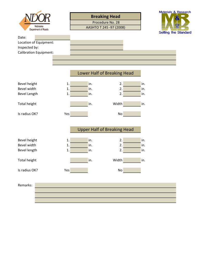
Date:Location of Equipment:Inspected by:Calibration Equipment:
Bevel height 1. in. 2. in.Bevel width 1. in. 2. in.Bevel Length 1. in. 2. in.
Total height in. Width in.
Is radius OK? Yes No
Bevel height 1. in. 2. in.Bevel width 1. in. 2. in.Bevel length 1. in. 2. in.
Total height in. Width in.
Is radius OK? Yes No
Remarks:
Procedure No. 28Breaking Head
AASHTO T 245 -97 (2008)
Lower Half of Breaking Head
Upper Half of Breaking Head

Equipment Checked:
Purpose:This procedure provides instructions for calibrating the ignition oven balance.
Inspection Equipment Required:1. 8000 gram calibration mass.
Tolerance:The equipment checked shall meet the tolerances specified in the test method listedabove.
Procedure:1. For calibrating the ignition oven balance, follow the Preventive Maintenance and Servicing Manual procedure.
Verification Interval:12 months
Report:A copy must be retained in the Testing Facilities files for review.
IGNITION OVEN (AASHTO T 308-10)
Procedure for Verifying Ignition OvenProcedure No. 38

CERTIFICATE OF VERIFICATION
DATE -
EQUIPMENT VERIFIED -
EQUIPMENT SERIAL NUMBER -
METHOD USED FOR ACCEPTANCE -
CALIBRATION EQUIPMENT USED -
1000 gm(Read-out on Ignition Oven) 3000 gm
5000 gm8000 gm
EQUIPMENT CHECKED BY -
LOCATION OF EQUIPMENT -
This certificate is issued for the aforementioned equipment and certifies that the equipment has
been checked and found to comply with the requirements set forth in the method listed above.
In order for this equipment to remain in service it must be recertified on the following date and
must comply with the latest methods listed at that time.
NEXT CALIBRATION DUE -
Remarks
Toledo Weights 8000 Grams
IGNITION OVEN
Procedure No. 38AASHTO T 308-10
Refer to Operator's Manual (To Span Calibrate the Balance)
VERIFICATION WEIGHTS -

Equipment Checked
This procedure provides for calibrating the gyratory ram pressure, angle of gyration,gyration frequency and LVDT.
1. Calibration kit, including equipment to verify and calibrate the pressure and angle.
The equipment checked shall meet the tolerance specified in the equipment ownersmanual.
The procedure for calibrating the gyratory compactor is located in the Manual ofOperation and Maintenance for Troxler Model 4140 and 4141. All other gyratoriesare calibrated by an outside source and will require certification documents fromthose companies.
12 months
A copy of the certificate of calibration must be retained in the Testing Facilities filesfor review.
Tolerance:
Procedure:
Verification Interval:
Report:
Procedure for Verifying Gyratory CompactorsProcedure No. 37
GYRATORY COMPACTOR ( AASHTO T 312-11)
Purpose:
Inspection Equipment Required:

1Date
kPa
kPa
2TOP BOTTOM Avg. Tolerance
Date Internal Angle 0 1.16 +/- .02
Deg. External Angle (If Measured) Deg.1.25 +/- .02
600 kPa 150 mm
3Date y/n
mm mm
kPa 150 mm
4 Performed as manufacturers recommendation.Date
30.0 RPM RPM
5
y/n y/n
REMARKS
Gyratory CompactorProcedure No. 37
AASHTO T 312-11
GYRATORY COMPACTOR CALIBRATION
LABORATORY NAME
LOCATION OF LABORATORY
TYPE OF GYRATORY MODEL OF GYRATORY
SERIAL NUMBER CALIBRATION KIT USED
CALIBRATION PERFORMED BY CALIBRATION KIT LAST CALIBRATEDDAVE-2 CALIBRATION KIT LAST CALIBRATED
COMPANY I.D. TAG # COMPACTOR LAST CALIBRATED
PRESSURE CALIBRATION
System Load Cell TOLERANCE -- 3 Percent or +/- 18 kPa
Calibration Load Cell
ANGLE CALIBRATION MOLDS USED
Measured Internal Angle
Pressure Mold Size
HEIGHT CALIBRATIONDaily File Kept
Actual Measured
Pressure Mold Size
ROTATION CALIBRATION
Target Measured
MAINTENANCEFollow manufacturers recommended schedule of maintenance. (Includes vacuuming, degreasing, lubricating,and inspecting for loose or worn parts)Kept Clean Well Greased
OTHER MAINTENANCE PERFORMED -

Equipment Checked:
Purpose:This procedure provides instructions for checking the critical dimensions of the moldsand the heads used in this test method.
Inspection Equipment Required:1. Calipers or steel rule capable of measuring to 0.01 millimeters.2. Surface Comparator.3. Rockwell Hardness Tester.4. Bore gauge.
Procedure:1. Measure and record the inside diameter of the mold to the nearest 0.01 mm. Rotate
2. Measure and record the height of the mold to the nearest millimeter. Repeat this
4. Check the smoothness of the molds and bottom plate surfaces that are in contact with the specimen. Use a surface comparator. (Follow owners manual)5. Check the Rockwell Hardness of the molds and bottom plates with a Rockwell Hardness tester. (Follow owners manual) Note: Only new molds need the hardness tested.6. Measure and record the diameter gyratory ram at intervals of 120 degrees to the nearest millimeter.
Verification Interval:12 months
Report:A copy must be retained in the Testing Facilities files for review.
3. Measure the diameter of the mold bottoms at intervals of 60 degrees around the plate.
GYRATORY MOLDS AND RAM HEADS (AASHTO T 312-11)
Procedure for Verifying Gyratory Molds and Ram HeadsProcedure No. 36
procedure at the top, bottom and maximum wear position. the mold 60 degrees and measure and record the inside diameter again. Perform this
procedure at intervals of 120 degrees around the mold.

DATE ----
LOCATION OF EQUIPMENT --
EQUIPMENT CHECKED BY --
METHOD USED FOR ACCEPTANCE -- AASHTO Designation: TP4-00 Section 4.2 Specimen Molds including Note 2 that follows.
CALIBRATION EQUIPMENT USED -- S-22 MICROFINISH COMPARATOR SURFACE FINISH SCALE AND DIGITAL CALIPERS
GYRATORY MOLD #1 1st Reading 2nd Reading 3rd Reading AverageWall Thickness - (7.5 mm thickness min.) 0Inside Diameter - (149.90 to 150.00 mm) 0Height of Mold - (250 mm minimum) 0
0.00GYRATORY MOLD #2 1st Reading 2nd Reading 3rd Reading Average
Wall Thickness - (7.5 mm thickness min.) 0Inside Diameter - (149.90 to 150.00 mm) 0Height of Mold - (250 mm minimum) 0
0.001st Reading 2nd Reading 3rd Reading Average
Wall Thickness - (7.5 mm thickness min.) 0Inside Diameter - (149.90 to 150.00 mm) 0Height of Mold - (250 mm minimum) 0
0.001st Reading 2nd Reading 3rd Reading Average
Wall Thickness - (7.5 mm thickness min.) 0Inside Diameter - (149.90 to 150.00 mm) 0Height of Mold - (250 mm minimum) 0
0.00
Mold # 1 2 3 4
Base -
NEXT CALIBRATION DATE -
Maximum Wear of Mold @ 115mm
SURFACE FINISH OF MOLDS-- (1.60 um or smoother)
ROCKWELL HARDNESS (min. C48, One time only)
FOWLER CYLINDER BORE GAUGE #FOW72-646-200
Maximum Wear of Mold @ 115mm
Maximum Wear of Mold @ 115mmGYRATORY MOLD #3
Maximum Wear of Mold @ 115mmGYRATORY MOLD #4
Gyratory MoldsProcedure No. 36
AASHTO T-312-11
GYRATORY MOLD CALIBRATION

Equipment Checked:
Purpose:This procedure provides instructions for checking the critical dimensions of the moldsused in this test method.
Inspection Equipment Required:1. Calipers capable of measuring an inside diameter of 4 in. and readable to 0.001 in.
Tolerance:The diameter of the molds checked shall meet the dimensional tolerances specified in the applicable test method listed above.
Procedure:1. Measure and record the inside diameter of the mold to the nearest 0.001 in. Rotate mold 90 degrees and measure and record again.2. Turn the mold over and repeat Step 1.3. Measure and record the height of the mold, less its collar to the nearest 0.1 in. Repeat this procedure at intervals of 90 degrees around the mold and record.
Verification Interval:12 months
Report:A copy must be retained in the Testing Facilities files for review.
Procedure for Verifying Marshall MoldsProcedure No. 3
MARSHALL MOLDS (AASHTO T 245-97 2008)

DATE ----
LOCATION OF EQUIPMENT --
EQUIPMENT CHECKED BY --
NEXT CALIBRATION DATE -
1 1st Reading 2nd Reading 3rd Reading Average000
Collar & Base Plate Fit Mold ? -2 1st Reading 2nd Reading 3rd Reading Average
000
Collar & Base Plate Fit Mold ? -3 1st Reading 2nd Reading 3rd Reading Average
000
Collar & Base Plate Fit Mold ? -4 1st Reading 2nd Reading 3rd Reading Average
000
Collar & Base Plate Fit Mold ? -5 1st Reading 2nd Reading 3rd Reading Average
000
Collar & Base Plate Fit Mold ? -6 1st Reading 2nd Reading 3rd Reading Average
000
Collar & Base Plate Fit Mold ? -
Sets of Complete Molds in Laboratory -------
CALIBRATION EQUIPMENT USED --------- DIGITAL CALIPERS
MARSHALL MOLD # Wall Thickness - Inside Diameter - (3.995 - 4.005 in)Height of Mold -
MARSHALL MOLD # Wall Thickness - Inside Diameter - (3.995 - 4.005 in)Height of Mold -
MARSHALL MOLD # Wall Thickness - Inside Diameter - (3.995 - 4.005 in)Height of Mold -
MARSHALL MOLD #
MARSHALL MOLD # Wall Thickness - Inside Diameter - (3.995 - 4.005 in)
Wall Thickness - Inside Diameter - (3.995 - 4.005 in)Height of Mold -
MARSHALL MOLD # Wall Thickness - Inside Diameter - (3.995 - 4.005 in)
Height of Mold -
Marshall MoldsProcedure No, 3
AASHTO T-245-97 (2008)
MARSHALL MOLD CALIBRATION
Height of Mold -
REMARKS -

Equipment Checked:
Purpose:This method provides instructions for checking the pressure developed by vacuumpumps for the Rice Test.
Procedure:1. Connect the vacuum pump to the vacuum chamber.2. Place a manometer in series between the pump and the vacuum chamber being sure all connections are tight.3. Start the pump and allow it to run for at least 5 minutes to allow the system to stabilize.4. Record the vacuum attained and the serial numbers of pump and manometer being used.
Verification Interval:12 months
Report:A copy must be retained in the Testing Facilities files for review.
Procedure for Verifying Vacuum System PressureProcedure No. 23
VACUUM SYSTEM (AASHTO T 209-10)

Date:Location of Equipment:Checked by:Calibration Equipment Used:
Yes/No Yes/No Yes/No
Monthly Y/N Monthly Y/N Monthly Y/N
Yes/No Yes/No Yes/No
Yes/No Yes/No Yes/No
mm Hg mm Hg mm Hg
Yes/No Yes/No Yes/No
Monthly Y/N Monthly Y/N Monthly Y/N
Yes/No Yes/No Yes/No
Yes/No Yes/No Yes/No
mm Hg mm Hg mm Hg
Remarks:
Manometer TypeSystem No.
Vacuum/ Bowl or Flask
1 2 3
VERIFYING VACUUM SYSTEM PRESSURE
AASHTO T 209-10Procedure No. 23
VACUUM SYSTEMS 1-3
Bowl or Flask CalibratedWire Mesh on Lid Opening
Pump Type No. of Moisture TrapsMicro Valve Installed
Heater & Overflow Y/NWater Bath Heater & Overflow Y/N Heater & Overflow Y/N
Vacuum Pressure Obtained (25.0-30.0mm Hg.)
Vibrating Shaker TableScale Used (Type)System Location
Manometer TypePump Type
Micro Valve Installed
Vibrating Shaker Table
Bowl or Flask CalibratedVacuum/ Bowl or Flask
Wire Mesh on Lid Opening
Water Bath
Scale Used (Type)
VACUUM SYSTEMS 4-6System No. 4 5 6
Heater & Overflow Y/N Heater & Overflow Y/N Heater & Overflow Y/N
No. of Moisture Traps
Vacuum Pressure Obtained (25.0-30.0mm Hg.)System Location

Equipment Checked:
Purpose:This method provides instructions for checking the rammer weight and drop heightof the manual and mechanical compactors.
Inspection Equipment Required:1. Hammer and punch for removing the spring pins which hold the upper collar on the rammer guide rod.2. Wrench for removing the upper guide rod holder.3. Balance, capacity of 10 kg and readable to the nearest 1.0 gram.4. Ruler capable of measurement to the nearest 1.0 mm.
Tolerance:The mass and drop height of the rammer shall meet the requirements set forthin test method AASHTO T 245.
Procedure:1. Measure and record the rammer drop height to the nearest 1.0 mm.2. Using the required tools remove the hammer from the guide rod.3. Weigh only the rammer and record the weight to the nearest gram.4. On multiple rammer type compactors mark each rammer with some form of identification for future inspections.5. Record the rammer identification and its weight.
Verification Interval:36 month - Manual36 month - Mechanical
Report:A copy must be retained in the Testing Facilities files for review.
Procedure for Verifying the Rammer Weight and Drop Height ofManual and Mechanical Compactors
Procedure No. 6
MANUAL AND MECHANICAL COMPACTORS (AASHTO T 245-97 2008)

Date:
Location of Equipment:Checked by:
1 2 3 4 5 6 7 8
9 10 11 12 13 14 15 16
Calibration Every 36 MonthsRemarks:
Weight of slide rammer only (1.0 gm)
Manual and Mechanical Compaction HammersProcedure No. 6
AASHTO T245-97 (2008)
Mechanical Compaction Hammers 9-16
Next Calibration Date -
Manual Compaction Hammers
Drop Height (Nearest 1.0 mm)
Drop Height (Nearest 1.0 mm)
Drop Height (Nearest 1.0 mm)
Compaction Hammer No.
Compaction Hammer No.
Compaction Hammer No.
Mechanical Compaction Hammers 1-8
Total Weight of Hammer (1.0 gm)
Total Weight of Hammer (1.0 gm)
Total Weight of Hammer (1.0 gm)
Weight of slide rammer only (1.0 gm)
Weight of slide rammer only (1.0 gm)

Equipment Checked:
Purpose:This method provides instructions for checking the calibration of the mechanicalcompactor.
Inspection Equipment Required:1. Scale conforming to the requirements of AASHTO M 231 and equipped with a suspension apparatus and water bath for weighing a specimen in water and air.2. Oven or hot plate for heating the specimen prior to compacting.3. Mixing equipment and support equipment for blending all of the components of the test mix.4. Hand compaction hammer meeting the requirements set forth in AASHTO T 245.
Procedure:1. Mix a 3/4" to 3/8" nominal size asphaltic concrete batch of 7400 grams minimum.2. Produce three compacted specimens following the procedure set forth in AASHTO T 245 using the mechanical compactor.3. Produce three compacted specimens following the procedure set forth in AASHTO T 245 using the manual hammers.4. Determine the bulk specific gravity of each compacted specimen per AASHTO T 166 and record the results.5. Average the three specific gravity result from the manual hammer and the mechanical compactor. Record the two averages.6. Determine if the average bulk specific gravity from the mechanical compacted specimens is within + 5% of the average bulk specific gravity obtained from the manual compacted specimens.
Verification Interval:36 months
Report:A copy must be retained in the Testing Facilities files for review.
Procedure for Calibration of Mechanical CompactorsProcedure No. 6A
MECHCANICAL COMPACTOR (AASHTO T 245-97 2008)

Date:Location of Equipment:
Serial No.
Checked by:
Number of blows per side
Bulk specific gravity of manual compacted specimens
1.2. Average 03.
Number of blow per side
Bulk specific gravity of mechanical compacted specimens
1.2. Average 03.
Is the average bulk specific gravity obtained from the mechanical prepared specimens within + 5% of the average bulk specific gravity from the manual prepared specimens?
Yes NoPercentage difference between mechanical and manual
Calibration Every 36 Months
Remarks:
Manufacturer of Compactor
Next Calibration Date -
50
Manual Compacted Specimens
Procedure No. 6ACalibration of Mechanical Compactors
AASHTO T 245 - 97 (2008)
50
Mechanical Compacted Specimens

Equipment Checked:
Purpose:This method provides instructions for calibrataing Pressure Air Meter - Type B.
Procedure:The procedures performed for calibrating Pressure Air Meter shall be in accordance with themeter type being employed. Refer to ASTM C 231, A1. CALIBRATION OF APPARATUS.
There are varying versions of Pressure Air Meters on the market. It may be necessary to follow the manufacturers instructions on calibrating the air meter if ASTM procedures do notapply to meter being calibrated.
Verification Interval:12 months
Report:A copy must be retained in the Testing Facilities files for review.
Procedure for Calibrating Pressure Air Meter - Type BProcedure No. 61
Pressure Air Meter - Type B (ASTM C 231-10)

Date:Inspected by:Calibration Equipment Used:
Date: Date:Air Meter No.: Air Meter No.:Initial Reading: Initial Reading:
Date: Date:Air Meter No.: Air Meter No.:Initial Reading: Initial Reading:
Date: Date:Air Meter No.: Air Meter No.:Initial Reading: Initial Reading:
Date: Date:Air Meter No.: Air Meter No.:Initial Reading: Initial Reading:
Date: Date:Air Meter No.: Air Meter No.:Initial Reading: Initial Reading:
Remarks:
Checked at 5%Checked at 10%
Pressure Air Meter - Type BProcedure No. 61ASTM C 231 - 10
Checked at 15%
Checked at 15%Condition of Meter
Checked at 15%Condition of Meter
Checked at 5%Checked at 10%
Checked at 5%Checked at 10%
Location of Equipment
Checked at 5%Checked at 5%Checked at 10%Checked at 15%Condition of Meter
Checked at 10%
Condition of Meter
Checked at 5%
Checked at 5%
Checked at 10%Checked at 15%Condition of Meter
Checked at 15%
Checked at 10%Checked at 15%
Checked at 5%
Condition of Meter
Checked at 10%Checked at 15%Condition of Meter
Condition of Meter
Condition of Meter
Checked at 5%Checked at 10%Checked at 15%Condition of Meter
Checked at 5%Checked at 10%Checked at 15%

Equipment Checked:
Purpose:This method provides instruction for checking the planeness of the bearing blocks andretainers of the compression testing machine as described in ASTM C 39 and ASTM C 1231.
Inspection Equipment Required:1. Steel rule, caliper. Depth gauge (optional)2. Feeler gauge.
Tolerance:The critical dimensions shall meet the requirements set forth in ASTM C 39 and ASTM C 1231.
Procedure:The units shall be checked and any deviation from the requirement shall be repaired priorto placing the unit back in service.
Verification Interval:12 months
Report:A copy must be retained in the Testing Facilities files for review.
Procedure for Verifying Bearing Blocks and RetainersProcedure No. 11
BEARING BLOCK (ASTM C 39 M-11a, RETAINERS (ASTM C 1231 M-10a)

Date:Location of Equipment:Equipment Serial No.Checked by:Calibration Equipment Used:
Diameter (Cylinder Head) 1. 2. Is face plane? Y / NDiameter (Cube Head) 1. 2. Is face plane? Y / N
If not plane, note the amount of wear.
If lower bearing block is round, note the diameter.
Diameter (Cylinder Head) 1. 2. Is face plane? Y / NDiameter (Cube Head) 1. 2. Is face plane? Y / N
If not plane, note the amount of wear.
Retainer Diameter Suface Condition (Good, Fair or Poor)
Retainer Diameter Suface Condition (Good, Fair or Poor)
Remarks:
and RetainersProcedure No. 11
ASTM C 39 M-11a & ASTM C 1231 M-10a
Compression Machine Bearing Block Planeness
Retainers (Set of Two)
Upper Bearing Blocks
Lower Bearing Blocks

Equipment Checked:
Purpose:This method provides requirements for moist rooms and water storage tanks where concrete specimens are stored.
Inspection Equipment Required:1. A calibrated thermometer either Fahrenheit or Celsius graduated in 1.0° increments having a range which includes the temperature range to be checked.2. Or a certified Digital temperature measuring device. 3. A sling psychrometer or other moisture measuring device.
Tolerance:The equipment must meet the tolerances specified in test method ASTM C 511.Moist Rooms & water storage tanks shall have a temperature of 23.0 ± 2.0 C.(69.8 - 77.0 F). Moist rooms shall have a humidity of not less than 95%.
Procedure:Check the temperature of the rooms and tanks with a thermometer or digitaltemperature measuring device. Record the results on the verification worksheet.If a chart or digital recorder is hooked up to or in the moist room or to the tank record that result also on the worksheet. Check the humidity of the moist room with a sling psychrometer or other moisture measuring device. Record the result on the verification worksheet. If a recorder is hooked up to monitor the humidity in the moist room record that reading also on the verification worksheet. Visually inspect the tank to see if it issaturated with calcium hydroxide. (11.36g/1gl)
Verification Interval:12 months
Report:A copy must be retained in the Testing Facilities files for review.
Procedure for Verifying Moist Room & Water Storage Tanks Procedure No. 62
Moist Room & Water Storage Tanks (ASTM C511-09)

Date:Inspected by:Calibration Equipment Used:
Date
(Monthly) Recorder Thermometer Recorder Psychrometer
Date
(Monthly) Recorder Thermometer
Conformance VerificationProcedure No. 62ASTM C 511 - 09
Moisture Room & Water Storage Tank
Moist RoomTemperature Humidity
Inspector Comments
Water Storage TankTemperature
Inspector Comments

Material Checked:
Purpose:This method provides instructions for checking the strength of capping compound.
Inspection Equipment Required:1. A calibrated concrete compression machine.2. A heated pot for heating the capping compound.3. Cube molds.4. A verified thermometer for checking the temperature of heated capping compound.5. Straightedge and feeler gauge.
Tolerance:1. Cylinder strength of 500 to 7000 psi requires 5000 minimum psi for mortar.2. Cylinder strength above 7000 requires compressive strength not less than the cylinder.3. Average thickness of the cap at 500 to 7000 psi shall not exceed 1/4 inch.4. Average thickness of the cap above 7000 psi shall not exceed 1/8 inch.
Procedure:1. Plug in mortar pot and check molten sulfur contents to verify temperature range of 265 - 290 °F.2. Stir contents.3. Lightly coat three cube molds with oil.4. Using ladle, fill molds with sulfur to the top of filling hole. Wait 15 minutes and refill to top.5. After cubes have become hard, strip from molds without breaking off knobs formed by the filling hole in the cover plate.6. Remove sharp edges and fins from the cubes. Also remove the oil.7. Check planeness of cubes to within 0.002 of an inch.8. Test for strength not less than 24 hours after molding.9. Test for compressive strength in accordance to C 109.
Verification interval:Receipt of a new lot
Report:A copy must be retained in the Testing Facilities files for review.
Procedure for Verifying Compressive Strength for Capping CompoundProcedure No. 63
CAPPING COMPOUND (ASTM C617M-11 & ASTM C109M-11a)

Date:Location of Equipment:Checked by:Calibration Equipment Used:
Sulfur ManufacturerShipment DateDate Cube MadeDate Cube Broke
Maximum permissible range between 2 specimens, 7.6% (average)Maximum permissible range between 3 specimens, 8.7% (average)
Cube #1 LoadCube #2 LoadCube #3 Load
Average
Strength average / 4
Remarks:
0.0
Compressive Strength for Capping CompoundProcedure No. 63
ASTM C 617 M-11 & ASTM C 109 M-11 a

Equipment Checked:
Purpose:This directive gives guidance for the calibration of unit weight measures used in Aggregate and Portland Cement Concrete Labs.
Inspection Equipment Required:1. A thermometer capable of being read to the nearest 1.0 degree F. 2. A piece of glass large enough to cover the entire top of the measure being calibrated.3. A scale capable of weighing the yield measure, glass, and the water within to the nearest 0.01 lbs.
Procedure:
Follow the procedure set forth in ASTM C 29, Section 8.
Verification Interval:12 months
Report:A copy must be retained in the Testing Facilities files for review.
Procedure for Verifying Unit Weight MeasureProcedure No. 26
UNIT WEIGHT MEASURE (ASTM C 138M-106)

Date: Location of EquipmentChecked by: Equipment Serial No.:
C F kg/m3 lb/ft315.6 60 999.01 62.36618.3 65 998.54 62.33621.1 70 997.97 62.301
(M) (M) 23.0 73.4 997.54 62.27423.9 75 997.32 62.261
(D) (D) 26.7 80 996.59 62.21629.4 85 995.83 62.166
lb. (V) lb. (V)1 2
Calculation M Avg. of 2D Avg of 2
AASHTO T 304-5 (8)
Bowl Number
BOWL DIMENSIONS
Outside diameterInside diameterInside heightOutside height
Unit Weight Measure Procedure No. 26
AASHTO C 138M-106
CALIBRATING UNIT WEIGHT MEASURE
Volume of Unit Weight nearest (lb.)
TEMPERATURE CHART
Volume of Bowl
Wt of Bowl-Glass Plate with Water
Wt of Bowl-Glass Plate
Net Mass of Water, (nearest lb.)
Density of H2O kg/m3 (Take off Chart)
the combined mass of measure, glass plate, and water by weighing. Following the finalweighing determine the mass of the clean,dry,empty measure for subsequent tests.
measure, being sure no air bubbles remain. Dry the outer surface of the measure and determine
Weigh the measure and glass plate. Fill the measure with deionized water at atemperature of 18 to 24 degree C. Record the temperature of the water. Slide the glass plate on the
V=1000
Weight of Bowl

Equipment Checked:
Purpose:This method provides instructions for calibrating a Volumetric Air Meter.
Inspection Equipment Required:1. Thermometer2. Glass Plate3. Scale
Procedure:1. Determine the volume of the bowl with an accuracy of at least 0.1 % by determining the mass of water required to fill it at room temperature and dividing it by the density of the water at the same temperature. See ASTM C 292. Determine the accuracy of the graduations on the neck of the top section of the air meter by filling the assembled measuring bowl and top section with water to the level of the mark for highest air content graduation.3. Add water in increments of 1.0% of the volume of the bowl to check the accuracy throughout the graduated range of air content. The error at any point throughout the graduated range shall not exceed 0.1% of air.4. Determine the volume of the calibrated cup using water at 70°F by the method outlined in Step 1.
Verification Interval:12 months
Report:A copy must be retained in the Testing Facilities files for review.
Procedure for Calibrating Volumetric Air Meter Procedure No. 65
Volumetric Air Meter (ASTM C 173-08)

Date:Inspected by:Air Meter No.:Calibration Equipment Required:
Mass of the water, glass plate & bowl: (W)Mass of glass plate & bowl: (M)Density of Water @ 70°F (62.3 lb/ft3): (D)
Volume: V=(W-M)/D(Bowl capacity is greater than 0.075 cubic feet (2L))
Mass of the water, glass plate & cup: (W)Mass of glass plate & cup: (M)Density of Water @ 70°F (62.3 lb/ft3): (D)
Volume: V=(W-M)/D(Capacity of or being graduated in increments equal to 1.00 ± .04% of the bowl volume)
9% 8% 7% 6% 5% 4% 3% 2% 1% 0%
(Graduations accurate to ± 0.1% by volume of the bowl)
Comments:
Volumetric Air MeterProcedure No.65ASTM C 173-08
Actual Reading @
Volume of Bowl
Volume of Cup
Calibration of Volumetric Air Meter Neck

D-18
Equipment Checked:
Purpose:This method provides instructions for checking the liquid limit device and grooving tool used in this test.
Inspection Equipment Required:1. Caliper capable of reading to nearest 0.01 mm.2. Dial micrometer.
Tolerance:The critical dimensions shall meet the requirements set forth in AASHTO T 89.
Procedure:1. Check all the critical dimensions for the liquid limit device's brass cup and the grooving tool. A picture of the apparatus and the necessary points to measure with the tolerances are printed in the AASHTO test procedure T 89.2. Where the cup comes in contact with the base, a small indention will be made. Measure the depth of this indention using the vertical dial micrometer to the nearest 0.01 in.3. Check the rim of the cup for excessive wear, which will cause it to become sharp rather than a milled flat surface. Rejection is at the inspector's judgment.4. Turn the crank slowly and note if the cup wobbles on the rise. Also check that the cup is fastened to the cam follower with mechanical rather than a welded connector.5. Check the inside of the cup for excessive wear, which will create a groove in the cup. Rejection is based on the judgment of the inspector.
Verification Interval:12 months
Report:A copy must be retained in the Testing Facilities file for review.
Procedure for Verifying Liquid Limit Devices And Grooving ToolsProcedure No. 18
LIQUID LIMIT DEVICE AND GROOVING TOOL (AASHTO T 89-10)

Date: Checked by:Location of Equipment:Calibration Equipment Used:
A B C N K L M
54 2 27 47 50 150 1252 0.1 0 1.5 5 5 5
1. 1.2. 2.3. 3.
Note: Plate "H" may be designed for using one securing screw.
Remarks:
Procedure No. 18Liquid Limit Equipment
AASHTO T 89-10
Thickness
Liquid Limit Device
Cup Assembly BaseDimension
DescriptionRadius of
CupThickness
of CupDepth of
Cup
Cup at Cam
Follower to Base
Length Width
Metric, mmTolerance, mm
Lab Equip. Number
Lab Equip. Number
Lab Equip. Number
Does cup wobble on rise? Cup groove condition?(Yes or No) (Good or Bad)
Curved End
Gage
a b c d e
ThicknessCutting
EdgeWidth Depth Length
10.0 2.0 13.5 10.0 15.90.1 0.1 0.1 0.2 NA
Lab Equip. Number
Lab Equip. Number
Lab Equip. Number
Note: An additional wear tolerance of 0.1 mm shall be allowed for dimension "b" for used grooving tools.
Remarks:
Tolerance, mm
Liquid Limit EquipmentAASHTO T 89-10
Grooving Tool
Dimensions
Description
Metric, mm

AΔ BΔ CΔ DΔ EΔ FΔ
2 + 0.1 11 + 0.2 40 + 0.5 8 + 0.1 50 + 0.5 2 + 0.1
Lab Equip.
Lab Equip.
Lab Equip.
G H J KΔ LΔ N10 Min. 13 60 10 + 0.05 60 Deg + 1 20
Lab Equip.
Lab Equip.
Lab Equip.
Remarks:
MM
Liquid Limit EquipmentASTM D 4318
Grooving Tool
Letter MM
Letter

Equipment Checked:
Purpose:This method provides instructions for checking the critical dimensions of the proctorhammer.
Inspection Equipment Used:1. Calipers readable to 0.001 inch.2. Tape measure readable to 1/16 inch.3. Balance, capacity 5 kg., readable to 1 gram.
Tolerance:Equipment shall meet the dimensional tolerances specified in the above test.
Procedure:1. Measure and record the diameter of the rammer face determined by taking two readings 90 degrees apart using the calipers.2. Pull up the handle, measure and record the drop height of the hammer. Determine this height inside the guide sleeve using the tape measure.3. Remove the hammer from the guide sleeve. Determine and record its mass to the nearest 1 gram.4. Measure and record the diameters of the vent holes near the end of the hammer.
Verification Interval:12 months
Report:A copy must be retained in the Testing Facilities files for review.
Procedure for Verifying Manual Compaction Hammers Procedure No. 5 & 5a
MANUAL HAMMER (AASHTO T 99-10 & T 180-10)

Date:Location of Equipment:Hammer Number:Checked By:Calibration Equipment Used:
Is the face flat? Yes NoDiameter of the face Dia. # 1 Dia. # 2 ( > 1.985 in.)Drop height of the rammer (12 + 0.06 in.)Rammer Mass (2495 + 9 grams)
Top # 1 Top # 2 Top # 3 Top # 4Bott. # 1 Bott. # 2 Bott. # 3 Bott # 4Specification: Min. 9.5mm or 3/8 in. Dia.
Note: Height may be impractical to adjust. Adjustments would have to be made with the height of the material that is being compacted.
Remarks:
Manual Rammer Procedure No. 5AASHTO T 99-10
Manual Rammer
Diameter of Vent Holes

Date:Location of Equipment: Hammer Number:Checked by:Calibration Equipment:
Is the face of the rammer flat? Yes NoDiameter of the face. Dia. # 1 Dia. # 2 (> 1.985 in.)Drop height of rammer. (18 + 0.06 in.)Rammer mass. (4536 + 9 grams)
Top # 1 Top # 2 Top # 3 Top # 4Bott. # 1 Bott. # 2 Bott. # 3 Bott. # 4Specification: Min. 9.5mm or 3/8 in. Dia.
Note: Height may be impractical to adjust. Adjustments would have to be made with the height of the material that is being compacted.
Remarks:
Manual RammerProcedure No. 5a
AASHTO T 180 - 10
Manual Rammer
Diameter of Vent Holes

D-22
Equipment Checked:
Purpose:This method provides instructions for checking the critical dimensions and masses required in the test method for this piece of equipment
Inspection Equipment Required:1. Outside caliper with a 2 in. capacity readable to 0.001 in.2. A hand rammer meeting the requirements of the AASHTO Test Method being checked (T 99 or T 180)3. A scale meeting AASHTO M 231 for Class G-2 and Class G-20.4. A drying oven capable of maintaining a temperature not to exceed 140o F.
Tolerance:The dimensions and masses shall meet the requirements set forth in the AASHTO TestMethod being checked (T 99 or T 180).
Procedure:1. Use the caliper to measure the diameter of the rammer face at two locations 90 degrees apart and record.2. Using the edge of the ruler check to see if the face of the rammer I s flat and record.3. Calibrate the mechanical rammer by using the procedure set forth I n ASTM D 2168.
Verification Interval:12 months
Report:A copy must be retained in the Testing Facilities files for review.
Procedure for Verifying Mechanical Soil RammersProcedure No. 22 & 22a
MECHANICAL SOIL RAMMER (AASHTO T 99-10)(AASHTO T 180-10)

Date:Location of Equipment: Hammer Number:Checked by:Calibration Equipment Used:
Is the face of the rammer flat? Yes NoDiameter of the face. Dia. # 1 Dia. # 2 (> 1.985 in.)Drop height of rammer. (12 + 0.06 in.)Rammer mass. (2495 + 9 grams)
Remarks:
Mechanical Rammer (AASHTO T 99)
Mechanical Soil RammerProcedure No. 22AASHTO T 99 - 10

Date:Equipment Make:Model Number:Serial Number:Manual Rammer Equipment Number Used:
W = [(γ'max - γmax) / γmax ] X 100*
* Follow procedure for Practice B detailed in ASTM D2168
= ( c1 ) micrometer reading before impact, manual rammer
= ( c2 ) micrometer reading after impact, manual rammer
= ( c'1 ) micrometer reading before impact, mechanical rammer
= ( c'2 ) micrometer reading after impact, mechanical rammer
= ( D ) deformation value for single lead cylinder, manual rammer
= ( D' ) deformation value for single lead cylinder, mechanical rammer = ( Dave and D'ave) average deformation values where v1 & v'1 values do not exceed +2.0%
= ( v1 ) % variation from the mean of individual deformation values, manual rammer
= ( v'1 ) % variation from the mean of individual deformation values, mechanical rammer
= ( v2 ) % difference of the average deformation value of the mechanical vs. manual rammer
= ( N ) number of tests
D = c1 - c2 D' = c'1 - c'2
v2 = [ (Dave - D'ave) / Dave] X 100
Remarks / Adjustments:
Practice B Calculations:
v1 = [ (D - Dave) / Dave ] X 100 v'1 = [ (D' - D'ave) / D'ave ] X 100
Calibration of Laboratory Mechanical RammersProcedure No. 22-1 (for Standard Proctor ASSHTO T 99-10)
ASTM D2168
is satisfactory for immediate use. If the absolute value of W is greater than 2.0,then follow the procedures detailed in ASTM D2168.
Dave = Σ ( c1 - c2 ) / N D'ave = Σ ( c'1 - c'2 ) / N
Calibration Practice: A or B
Practice A Calculations: = ( γmax ) the maximum dry unit weight obtained with the manual compactor
= ( γ'max ) the maximum dry unit weight obtained with the mechanical compactor
= ( W ) the percentage difference of maximum dry unit weight values
If the absolute value of W is equal to or less than 2.0, the mechanical compactor

Date:
Location of Equipment:Checked by:Calibration Equipment Used:
Hammer Number:Is the face of the rammer flat? Yes NoDiameter of the face. Dia. # 1 Dia. # 2 (> 1.985 in.)Drop height of rammer. (18 + 0.06 in.)Rammer mass. (4536 + 9 grams)
Hammer Number:Is the face of the rammer flat? Yes NoDiameter of the face. Dia. # 1 Dia. # 2 (> 1.985 in.)Drop height of rammer. (18 + 0.06 in.)Rammer mass. (4536 + 9 grams)
Hammer Number:Is the face of the rammer flat? Yes NoDiameter of the face. Dia. # 1 Dia. # 2 (> 1.985 in.)Drop height of rammer. (18 + 0.06 in.)Rammer mass. (4536 + 9 grams)
Remarks:
Mechanical Rammer #2 (AASHTO T 180)
Mechanical Rammer #3 (AASHTO T 180)
Mechanical Rammer #1 (AASHTO T 180)
Mechanical Soil RammerProcedure No. 22aAASHTO T 180 - 10

Date:Equipment Make:Model Number:Serial Number:Manual Rammer Equipment Number Used:
W = [(γ'max - γmax) / γmax ] X 100*
* Follow procedure for Practice B detailed in ASTM D2168
= ( c1 ) micrometer reading before impact, manual rammer
= ( c2 ) micrometer reading after impact, manual rammer
= ( c'1 ) micrometer reading before impact, mechanical rammer
= ( c'2 ) micrometer reading after impact, mechanical rammer
= ( D ) deformation value for single lead cylinder, manual rammer
= ( D' ) deformation value for single lead cylinder, mechanical rammer = ( Dave and D'ave) average deformation values where v1 & v'1 values do not exceed +2.0%
= ( v1 ) % variation from the mean of individual deformation values, manual rammer
= ( v'1 ) % variation from the mean of individual deformation values, mechanical rammer
= ( v2 ) % difference of the average deformation value of the mechanical vs. manual rammer
= ( N ) number of tests
D = c1 - c2 D' = c'1 - c'2
v2 = [ (Dave - D'ave) / Dave] X 100
Remarks / Adjustments:
Practice B Calculations:
Dave = Σ ( c1 - c2 ) / N D'ave = Σ ( c'1 - c'2 ) / N
v1 = [ (D - Dave) / Dave ] X 100 v'1 = [ (D' - D'ave) / D'ave ] X 100
= ( γ'max ) the maximum dry unit weight obtained with the mechanical compactor
= ( W ) the percentage difference of maximum dry unit weight values
If the absolute value of W is equal to or less than 2.0, the mechanical compactoris satisfactory for immediate use. If the absolute value of W is greater than 2.0,then follow the procedures detailed in ASTM D2168.
ASTM D2168
Calibration Practice: A or B
Practice A Calculations:
Procedure No. 22a-1 (for Modified Proctor ASSHTO T 180-10)Calibration of Laboratory Mechanical Rammers
= ( γmax ) the maximum dry unit weight obtained with the manual compactor

D-2
Date: 2-3-97Revised:
Equipment Checked: COMPACTION MOLDS (AASHTO T 99, T 180)
Purpose:This method provides instructions for checking the critical dimensions of the moldsused in this test.
Inspection Equipment Required:1. Calipers capable of measuring an inside diameter of 4 in. and readable to 0.001 in.2. Calipers capable of measuring an outside height of 6 in. and readable to 0.001 in. checked (T 99 or T 180)
Tolerance:Molds shall meet all dimension requirements set forth in the applicable test methodlisted above.
Procedure:1. Measure and record the inside diameter of the mold to nearest 0.001 in. Rotate mold 90 degrees and repeat the procedure. Turn the mold over and repeat.2. Measure and record the height of the mold less its collars to the nearest 0.001 in. Repeat this procedure at intervals of 90 degrees around the mold and record.
Verification Interval:12 months
Report:A copy must be retained in the Testing Facilities files for review.
Procedure for Verifying Compaction MoldsProcedure No. 2

Date:Location of Equipment:
Checked by:Calibration Equipment Used:
Dia. # 1 Ht. # 1 Dia. # 1 Ht. # 1Dia. # 2 Ht. # 2 Dia. # 2 Ht. # 2Dia. # 3 Ht. # 3 Dia. # 3 Ht. # 3Dia. # 4 Ht. # 4 Dia. # 4 Ht. # 4
Mold Number: Mold Number:0.000 0.000
0.0000 0.00000.00 0.00
Dia. # 1 Ht. # 1 Dia. # 1 Ht. # 1Dia. # 2 Ht. # 2 Dia. # 2 Ht. # 2Dia. # 3 Ht. # 3 Dia. # 3 Ht. # 3Dia. # 4 Ht. # 4 Dia. # 4 Ht. # 4
Mold Number: Mold Number:0.000 0.000
0.0000 0.00000.00 0.00
Note:
Remarks:
Compaction MoldProcedure No. 2
AASHTO T 99-10 & T 180-10
Ave. Diameter, in. Ave. Height, in.
Mold Measurements
Diameter, Inches Height, Inches Diameter, Inches Height, Inches4 inch Molds 4 inch Molds
0.000 0.000 0.000 0.000
( 4.000 + 0.016 ) ( 4.584 + 0.005 )
Ave. Diameter, in. Ave. Height, in.
Height, Inches
A mold that fails to meet manufacturing tolerances after continued service may remain
Ave. Diameter, in. Ave. Height, in. Ave. Diameter, in. Ave. Height, in.
Mold Measurements
Diameter, Inches
of the mold, calibrated in accordance with T 19M/T 19 for Unit Mass of Aggregate, is used inthe calculations.
0.000 0.000 0.000 0.000
Computed Volume, cu, InchesComputed Volume, cu, FeetComputed Volume, cu Cm.
Computed Volume, cu, InchesComputed Volume, cu, FeetComputed Volume, cu Cm.
in use provided those tolerances are not exceeded by more that 50 percent; and the volume
Height, Inches4 inch Molds 4 inch Molds
( 4.000 + 0.016 ) ( 4.584 + 0.005 ) ( 4.000 + 0.016 ) ( 4.584 + 0.005 )Diameter, Inches
Computed Volume, cu, InchesComputed Volume, cu, FeetComputed Volume, cu Cm.
Computed Volume, cu, InchesComputed Volume, cu, FeetComputed Volume, cu Cm.
( 4.000 + 0.016 ) ( 4.584 + 0.005 )

Date:Location of Equipment:
Checked by:Calibration Equipment Used:
Dia. # 1 Ht. # 1 Dia. # 1 Ht. # 1Dia. # 2 Ht. # 2 Dia. # 2 Ht. # 2Dia. # 3 Ht. # 3 Dia. # 3 Ht. # 3Dia. # 4 Ht. # 4 Dia. # 4 Ht. # 4
Mold Number: Mold Number:0.000 0.000
0.0000 0.00000.00 0.00
Dia. # 1 Ht. # 1 Dia. # 1 Ht. # 1Dia. # 2 Ht. # 2 Dia. # 2 Ht. # 2Dia. # 3 Ht. # 3 Dia. # 3 Ht. # 3Dia. # 4 Ht. # 4 Dia. # 4 Ht. # 4
Mold Number: Mold Number:0.000 0.000
0.0000 0.00000.00 0.00
Note:
Remarks:
Compaction MoldProcedure No. 2
AASHTO T 99-10 & T 180-10
Mold Measurements
Diameter, Inches Height, inches Diameter, Inches Height, inches( 6.000 + 0.026 ) ( 4.584 + 0.005 ) ( 6.000 + 0.026 ) ( 4.584 + 0.005 )
Ave. Diameter, in. Ave. Height, in. Ave. Diameter, in. Ave. Height, in.
Computed Volume, cu Cm.
Mold Measurements
0.000 0.000 0.000 0.000
Computed Volume, cu, InchesComputed Volume, cu, Feet
Diameter, Inches Height, inches( 6.000 + 0.026 ) ( 4.584 + 0.005 ) ( 6.000 + 0.026 ) ( 4.584 + 0.005 )
the calculations.
Ave. Diameter, in. Ave. Height, in. Ave. Diameter, in. Ave. Height, in.0.000 0.000 0.000
Computed Volume, cu, InchesComputed Volume, cu, FeetComputed Volume, cu Cm.
Computed Volume, cu, InchesComputed Volume, cu, FeetComputed Volume, cu Cm.
A mold that fails to meet manufacturing tolerances after continued service may remainin use provided those tolerances are not exceeded by more that 50 percent; and the volumeof the mold, calibrated in accordance with T 19M/T 19 for Unit Mass of Aggregate, is used in
Computed Volume, cu, InchesComputed Volume, cu, FeetComputed Volume, cu Cm.
6 inch Molds 6 inch Molds
6 inch Molds 6 inch Molds
0.000
Diameter, Inches Height, inches

D-19
Equipment Checked:
Purpose:This method provides instructions for checking the steel straightedge used in AASHTOTest Methods T 99 and T 180.
Inspection Equipment Required:1. Ruler.2. Feeler gauge.
Tolerance:The critical dimensions shall meet the requirements set forth in AASHTO T 99 and T 180.
Procedure:1. Measure the length with a ruler and record.2. Place the straightedge so that the beveled edge is down on a flat surface and using a 0.01 in. thickness gauge, try to pass the gauge between the edge of the unit and the flat surface. If the gauge can be slipped between the unit and the flat surface the straightedge shall have to be repaired.
Verification Interval:12 months
Report:A copy must be retained in the Testing Facilities files for review.
Procedure for Verifying StraightedgesProcedure No. 19
STRAIGHTEDGE (AASHTO T 99-10, T 180-10)
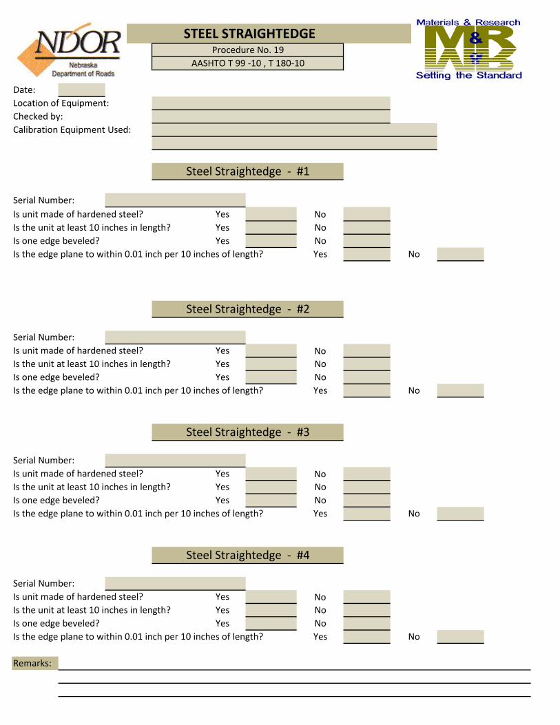
Date:Location of Equipment:Checked by:Calibration Equipment Used:
Serial Number:Is unit made of hardened steel? Yes NoIs the unit at least 10 inches in length? Yes NoIs one edge beveled? Yes NoIs the edge plane to within 0.01 inch per 10 inches of length? Yes No
Serial Number:Is unit made of hardened steel? Yes NoIs the unit at least 10 inches in length? Yes NoIs one edge beveled? Yes NoIs the edge plane to within 0.01 inch per 10 inches of length? Yes No
Serial Number:Is unit made of hardened steel? Yes NoIs the unit at least 10 inches in length? Yes NoIs one edge beveled? Yes NoIs the edge plane to within 0.01 inch per 10 inches of length? Yes No
Serial Number:Is unit made of hardened steel? Yes NoIs the unit at least 10 inches in length? Yes NoIs one edge beveled? Yes NoIs the edge plane to within 0.01 inch per 10 inches of length? Yes No
Remarks:
STEEL STRAIGHTEDGE Procedure No. 19
AASHTO T 99 -10 , T 180-10
Steel Straightedge - #4
Steel Straightedge - #1
Steel Straightedge - #2
Steel Straightedge - #3

D-8
Equipment Checked: SCALES AND BALANCES (AASHTO M231)
Purpose:This method provides instructions for checking the accuracy sensitivity of scales, balancesbalance weights used in all labs.
Inspection Equipment Required:1. Calibrated weights with certificates.2. Powder free gloves designed for handling these weights.
Tolerance:All AASHTO and ASTM tests requiring the use of scales and or balances have in their procedures a list of requirements for the weighing devices. It will be up to the inspector to check these requirements when checking and verifying this equipment.
Procedure:Each balance or scale will have its own worksheet. Choose the appropriate worksheet forthe balance or scale to be verified. Check the equipment through the entire range on theworksheet. It is recommended to calibrate the balance before verifying. Follow the ownersmanual for this procedure. Lab balance weights used only for verification purposes shall be verified against calibratedweights.
Verification Interval:12 months
Report:A copy for each scale or balance must be retained in the Testing Facilities files for review.
Procedure for Verifying Scales, Balances and Balance WeightsProcedure No. 8

Date : Serial No.:Checked by:Material:Scale No.:Calibration Equipment:
Weight Accuracy5000g .80g
2000g .40g
1000g .25g
500g .20g
200g .10g
100g .07g
50g .04g
20g .02g
10g .015g
5g .010g
2g .006g
1g .004g
Remarks:
Balance WeightsProcedure No. 8
AASHTO M 231 Table 4
Balance Weights

Date: Inspected By:Calibration Weights:Scale Serial No.:
Scale Capacity:
Remarks:
Analytical BalancesProcedure No. 8
1200g Capacity or LessClass C
Manufacturer:
Test Point Accuracy Required Accuracy
50 g .02 g
100 g .02 g
200 g .02 g
300 g .02 g
400 g .02 g
500 g .02 g
600 g .02 g
700 g .02 g
800 g .02 g
900 g .02 g
1000 g .02 g
1100 g .02 g
1200 g .02 g

Date: Location of Scale:Inspected By:Calibration Weights:Scale No.:Manufacturer:Scale Capacity:
Remarks:
General Purpose ScalesProcedure No. 8
Class G2
Test Point Accuracy Required Accuracy
50 g .2 g100 g .2 g200 g .2 g300 g .3 g400 g .4 g500 g .5 g
1000 g 1.0 g2000 g 2.0 g3000 g 3.0 g4000 g 4.0 g5000 g 5.0 g6000 g 6.0 g7000 g 7.0 g8000 g 8.0 g9000 g 9.0 g
10000 g 10.0 g11000 g 11.0 g12000 g 12.0 g13000 g 13.0 g14000 g 14.0 g15000 g 15.0 g16000 g 16.0 g

Date: Location of Scale:Inspected By:SN of Calibration Weights:Scale No.:Manufacturer:Scale Capacity:
Remarks:
General Purpose ScalesProcedure No. 8
Class G300 Special (Over 40 LB)
Test Point Accuracy Required Accuracy
10 lb .5 lb
20 lb .5 lb
30 lb .5 lb
40 lb .5 lb
50 lb .5 lb
60 lb .6 lb
90 lb .9 lb
120 lb 1.2 lb
150 lb 1.5 lb
180 lb 1.8 lb
210 lb 2.1 lb
240 lb 2.4 lb
270 lb 2.7 lb
300 lb 3.0 lb

Equipment Checked:
Purpose:This method provides instructions for checking drying ovens used in the laboratory.
Inspection Equipment Required:1. A calibrated thermometer either Fahrenheit or Celsius graduated in 1.0° increments having a range which includes the temperature range to be checked.2. A thermometer well to retain heat while the oven door is open.3. A clothes pin the hold the thermometer in such a manner as to enable the operator to read the scale easily.
Tolerance:Drying ovens shall be capable of maintaining a constant temperature range listed in theappropriate test methods.
Procedure:1. Place the thermometer inside the well with the clothes pin attached to the thermometer. Position the thermometer on the shelf where the samples are normally dried.2. Take the first reading at least 1 hour after closing the oven (oven should remain undisturbed).3. Take as many readings as necessary to determine if the temperature range is within the specified tolerance (three consecutive readings, taken no less that 1/2 hour apart, within the tolerance allowed are adequate).4. Adjust the temperature of the oven if an observed reading is outside the tolerance specified (allow at least 1/2 hr. for the temperature to stabilize between each adjustment. Return to step 3.
Verification Interval:12 months
Report:A copy must be retained in the Testing Facilities files for review.
Procedure for Verifying Ovens Procedure No. 1
DRYING OVENS

Date -Location of Equipment - Calibration Equipment Used -
Oven #1 Oven #2
Manufacturer ManufacturerModel No. Model No.Serial No. Serial No.
Oven Set Point Temperature Reading Oven Set Point Temperature ReadingF 20 min. F 20 min.
40 min. 40 min.60 min. 60 min.
Remarks Remarks
Oven #3 Oven #4
Manufacturer ManufacturerModel No. Model No.Serial No. Serial No.
Oven Set Point Temperature Reading Oven Set Point Temperature ReadingF 20 min. F 20 min.
40 min. 40 min.60 min. 60 min.
Remarks Remarks
Remarks
( 230+/- 9 Degrees F or 110 +/- 5 Degrees C) ( 230+/- 9 Degrees F or 110 +/- 5 Degrees C)
OvensProcedure No. 1
AASHTO T-208, T-216, T-265, T-296
( 230+/- 9 Degrees F or 110 +/- 5 Degrees C) ( 230+/- 9 Degrees F or 110 +/- 5 Degrees C)
Inspected by:
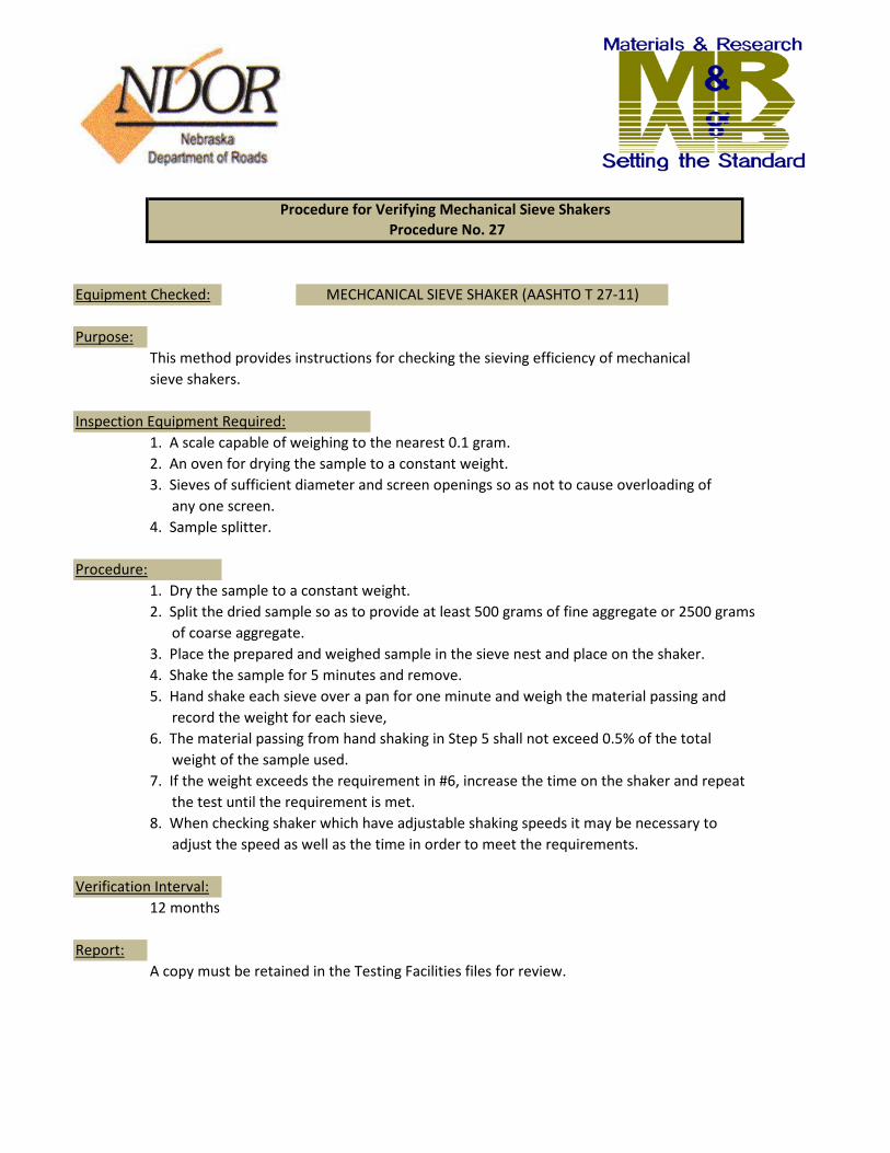
Equipment Checked:
Purpose:This method provides instructions for checking the sieving efficiency of mechanicalsieve shakers.
Inspection Equipment Required:1. A scale capable of weighing to the nearest 0.1 gram.2. An oven for drying the sample to a constant weight.3. Sieves of sufficient diameter and screen openings so as not to cause overloading of any one screen.4. Sample splitter.
Procedure:1. Dry the sample to a constant weight.2. Split the dried sample so as to provide at least 500 grams of fine aggregate or 2500 grams of coarse aggregate.3. Place the prepared and weighed sample in the sieve nest and place on the shaker.4. Shake the sample for 5 minutes and remove.5. Hand shake each sieve over a pan for one minute and weigh the material passing and record the weight for each sieve,6. The material passing from hand shaking in Step 5 shall not exceed 0.5% of the total weight of the sample used.7. If the weight exceeds the requirement in #6, increase the time on the shaker and repeat the test until the requirement is met.8. When checking shaker which have adjustable shaking speeds it may be necessary to adjust the speed as well as the time in order to meet the requirements.
Verification Interval:12 months
Report:A copy must be retained in the Testing Facilities files for review.
Procedure for Verifying Mechanical Sieve Shakers Procedure No. 27
MECHCANICAL SIEVE SHAKER (AASHTO T 27-11)

Date:Checked by:Shaker Serial No.:Manufacturer:Type of Aggregate used: Fine CoarseScale Serial Number:Oven Serial Number:Sieve Diameter: 8" 10" 12"
Initial Sample Weight: gm.
Sieve Screen Material PercentSerial No. No. Passing Passing
gm. %gm. %gm. %gm. %gm. %gm. %gm. %gm. %gm. %gm. %gm. %gm. %gm. %gm. %gm. %gm. %gm. %
Total Mechanical Shaker Time min.
NOTE: Use a new worksheet for each run and or type of aggregate used.
Mechanical Sieve ShakersSieving Thoroughness
Procedure No. 27AASHTO T 27 -11

D-25
Equipment Checked:
Purpose:This method provides instructions for visually checking sieves used in the laboratory.
Inspection Equipment Required:1. A method for providing a lighted background when viewing the sieve screen.2. A magnifier for close examination of the sieve screen.
Tolerance:The sieves examined shall meet the requirements set forth in AASHTO M 92.
Procedure:1. Check each sieve tag for the proper designation and standard opening size. This designation shall be in metric dimensions and in the case of older sieves the English and metric dimensions shall be both on the tag.2. Check the frame for excessive wear along the rim and for looseness between the top and bottom halves.3. Check the screen for loose wires, bowed screens, torn screens, creases I n the screen, broken screen wires, and deformation of the screen openings. These items are normally visible with the naked eye when viewed against a lighted background. The use of a magnifier will aid when viewing the finer screens.
Verification Interval:12 months
Report:A copy must be retained in the Testing Facilities files for review.
Procedure for Verifying SievesProcedure No. 25
SIEVES (AASHTO M 92-05)

Date:Location of Equipment:Checked by:Calibration Equipment Used:
Lab IdentificationDiameter of FrameScreen No.Frame ConditionScreen ConditionLabel Condition
Lab IdentificationDiameter of FrameScreen No.Frame ConditionScreen ConditionLabel Condition
Lab IdentificationDiameter of FrameScreen No.Frame ConditionScreen ConditionLabel Condition
Lab IdentificationDiameter of FrameScreen No.Frame ConditionScreen ConditionLabel Condition
Remarks:
Sieves
Wire Cloth Sieves for Testing PurposesProcedure No. 25AASHTO M 92 - 05

Equipment Checked:
Purpose:This method provides instructions for checking thermometers used in the laboratory and in the field.
Inspection Equipment Required:1. A calibrated thermometer either Fahrenheit or Celsius graduated in 1.0° increments having a range which includes the temperature range to be checked. A calibrated digital temperature measuring device is also acceptable.
Tolerance:The tolerance for mercury thermometers is plus or minus one scale division of that thermometer. Tolerance for spirit filled thermometers is plus or minus 1% of the total rangefor that thermometer. Tolerance for dial thermometers is plus or minus one scale division. Digital thermometers such as Oaktrons & Taylors used most commonly in water baths and inovens have a tolerance of plus or minus 3.6 degrees.
Procedure:Verify lab or field thermometers against a calibrated thermometer. Check each thermometerat two points if possible. Using water to perform the checks would be the best method.It does no have to be a commercially made water bath. It could be as simple as using a a bucket and adding hot water. A piece of Plexiglas with drilled holes works well whenplaced over a water bath. Clothes pins or other clips can be used to hold the thermometersin place while performing the check. Alternative methods may be used to achieve results.
Verification Intervals:12 months
Report:A copy must be retained for each thermometer tested and kept in the Testing Facilitiesfiles for review.
Procedure for Verifying ThermometersProcedure No. 64
Thermometers

Date:Checked By:Calibration Equipment Used:
Standard Thermometer Serial No. Laboratory Thermometer Serial No. ASTM No. ASTM No.
1. 1.2. 2.3. 3.4. 4.
Maximum scale allowed in accordance with ASTM E-1.Remarks:
Standard Thermometer Serial No. Laboratory Thermometer Serial No. ASTM No. ASTM No.
1. 1.2. 2.3. 3.4. 4.
Maximum scale allowed in accordance with ASTM E-1.Remarks:
Standard Thermometer Serial No. Laboratory Thermometer Serial No. ASTM No. ASTM No.
1. 1.2. 2.3. 3.4. 4.
Maximum scale allowed in accordance with ASTM E-1.Remarks:
ThermometerProcedure No. 64
ASTM E 77 - 07
Standard Thermometer Laboratory ThermometerTemperature Reading (°F or °C) Temperature Reading (°F or °C)
Standard Thermometer Laboratory ThermometerTemperature Reading (°F or °C) Temperature Reading (°F or °C)
Standard Thermometer Laboratory ThermometerTemperature Reading (°F or °C) Temperature Reading (°F or °C)