Embed Size (px)
Citation preview
Yellow Point
Catalog No. 8-2018.1 YP
2018
NEVER EXCEED PUBLISHED WORKING LOAD LIMIT
WARNINGCopyright © 2018
YOKE Industrial Corp.All Rights Reserved.2
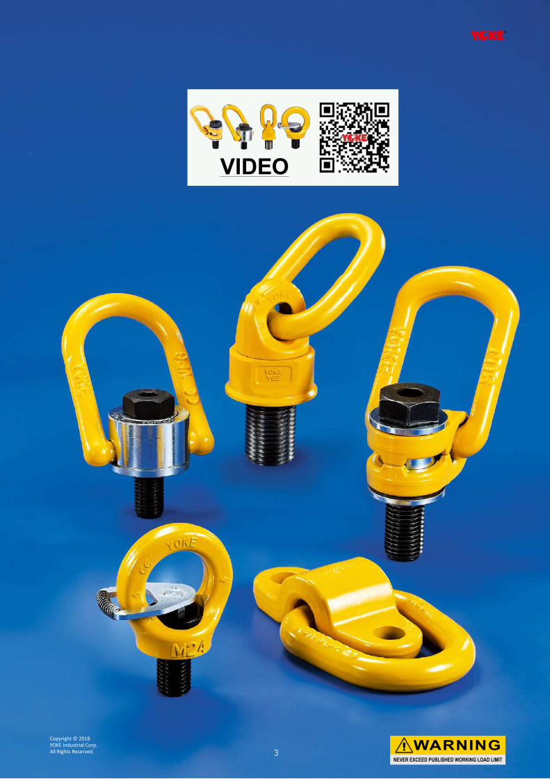
VIDEO
NEVER EXCEED PUBLISHED WORKING LOAD LIMIT
WARNINGCopyright © 2018 YOKE Industrial Corp.All Rights Reserved. 3
Yellow Point
NEVER EXCEED PUBLISHED WORKING LOAD LIMIT
WARNINGCopyright © 2018
YOKE Industrial Corp.All Rights Reserved.4
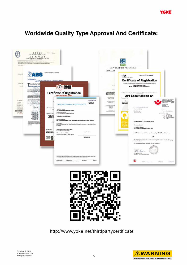
Worldwide Quality Type Approval And Certificate:
http://www.yoke.net/thirdpartycertificate
NEVER EXCEED PUBLISHED WORKING LOAD LIMIT
WARNINGCopyright © 2018 YOKE Industrial Corp.All Rights Reserved. 5
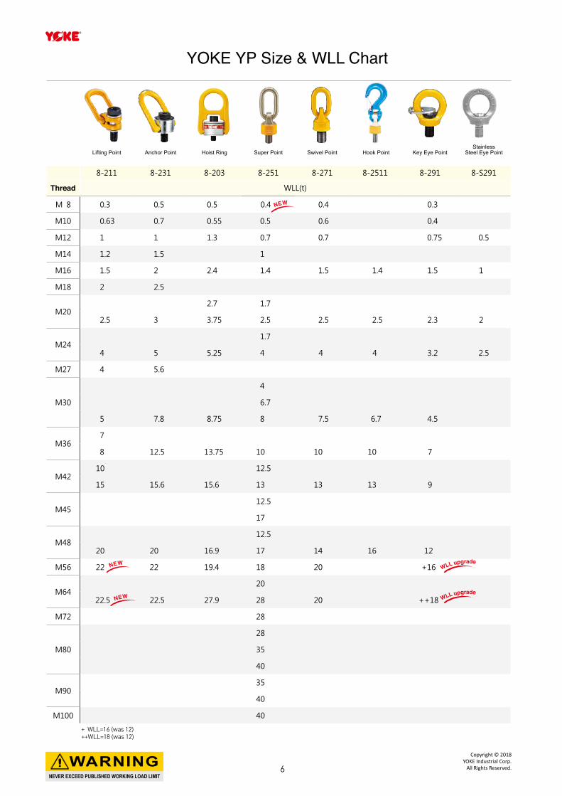
Lifting Point Anchor Point Hoist Ring Super Point Swivel Point Hook Point Key Eye PointStainless
Steel Eye Point
8-211 8-231 8-203 8-251 8-271 8-2511 8-291 8-S291
Thread WLL(t)
M 8 0.3 0.5 0.5 0.4 0.4 0.3
M10 0.63 0.7 0.55 0.5 0.6 0.4
M12 1 1 1.3 0.7 0.7 0.75 0.5
M14 1.2 1.5 1
M16 1.5 2 2.4 1.4 1.5 1.4 1.5 1
M18 2 2.5
M202.7 1.7
2.5 3 3.75 2.5 2.5 2.5 2.3 2
M241.7
4 5 5.25 4 4 4 3.2 2.5
M27 4 5.6
M30
4
6.7
5 7.8 8.75 8 7.5 6.7 4.5
M367
8 12.5 13.75 10 10 10 7
M4210 12.5
15 15.6 15.6 13 13 13 9
M4512.5
17
M4812.5
20 20 16.9 17 14 16 12
M56 22 22 19.4 18 20 +16
M6420
22.5 22.5 27.9 28 20 ++18
M72 28
M80
28
35
40
M9035
40
M100 40
YOKE YP Size & WLL Chart
NEW
NEW
NEW WLL upgrade
WLL upgrade
+ WLL=16 (was 12)++WLL=18 (was 12)
NEVER EXCEED PUBLISHED WORKING LOAD LIMIT
WARNINGCopyright © 2018
YOKE Industrial Corp.All Rights Reserved.6
NEVER EXCEED PUBLISHED WORKING LOAD LIMIT
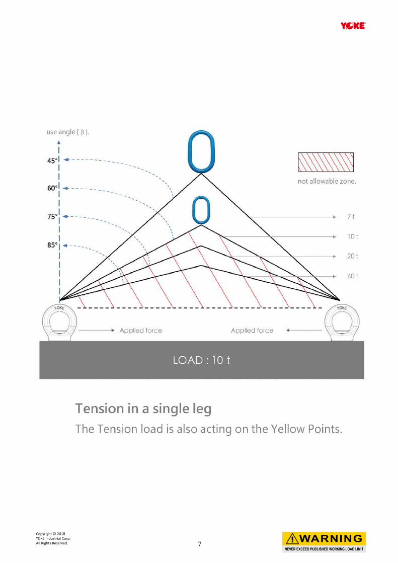
WARNINGCopyright © 2018 YOKE Industrial Corp.All Rights Reserved. 7
■ Magnaflux Crack Detection:
All forged components are individually magnaflux detected after heat treatment.
■ Proof Load Testing:
YOKE Yellow Points are proof load qualified to 2.5 times the Working Load Limit within 1% permanent deformation.
■ Dynamic Fatigue Testing: Batch samples of YOKE Yellow Points are Dynamic Fatigue Tested to 20,000 cycles at 1.5 times the Working Load Limit.
■ Ultimate Breaking Load Testing:Batch samples are tested in a static tensile testing machine until failure. Minimum ultimate force equals to the Working Load Limit times safety factor.
■ Spectrographic Analysis:To assure of the proper metallurgy content of all raw materials.
Quality Control, Testing, and Detecting during manufacturing
YOKE runs a constant and strict production facility with quality control in every manufacturing stage from raw materials to the completed product. YOKE is an ISO 9001 certified company and has Type Approval by the major international authorities from Deutsche Gesetzliche Unfallversicherung (DGUV) , ABS, API, and DNV. YOKE has achieved CNLA certification - Chinese National Laboratory Accreditation which ensures a quality research and development (R&D) department and unsurpassed product engineering.
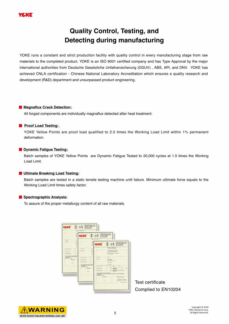
Test certificateComplied to EN10204
NEVER EXCEED PUBLISHED WORKING LOAD LIMIT
WARNINGCopyright © 2018
YOKE Industrial Corp.All Rights Reserved.8
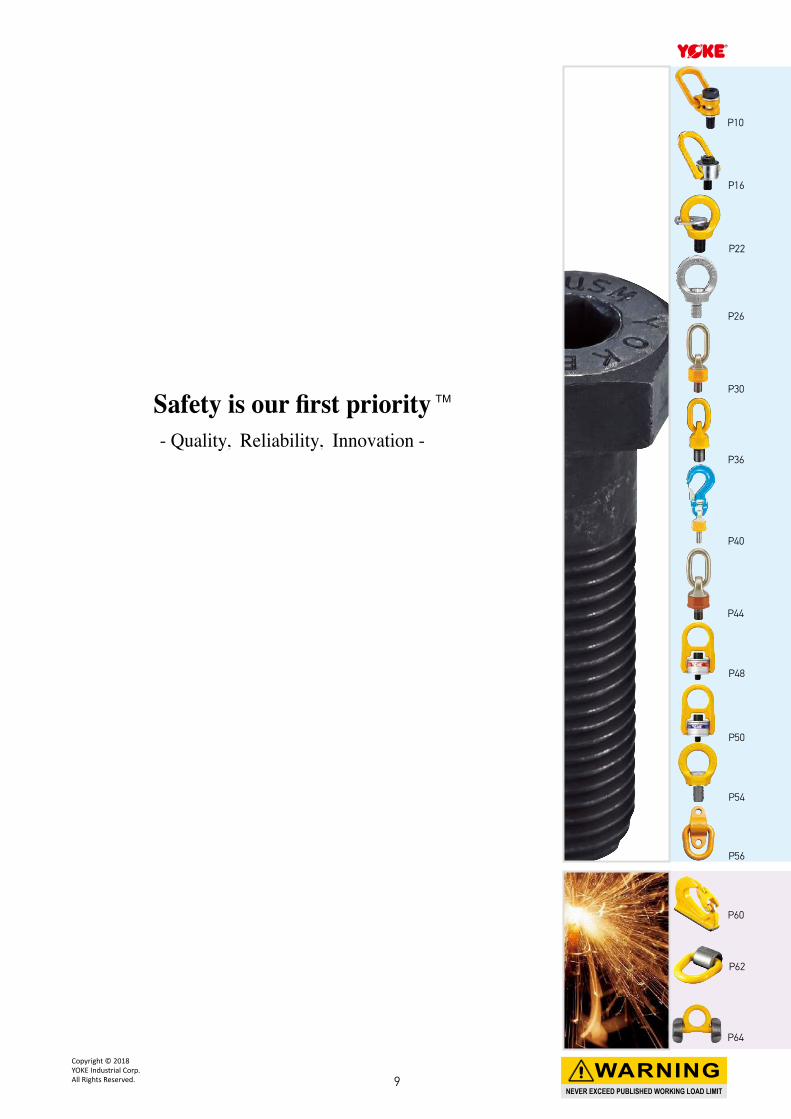
Safety is our first priority- Quality, Reliability, Innovation -
TM
P10
P60
P62
P64
P56
P54
P44
P22
P26
P16
P30
P36
P40
P48
P50
NEVER EXCEED PUBLISHED WORKING LOAD LIMIT
WARNINGCopyright © 2018 YOKE Industrial Corp.All Rights Reserved. 9
E
M
H C
F
A
D
G
B
SSW
360° Rotation
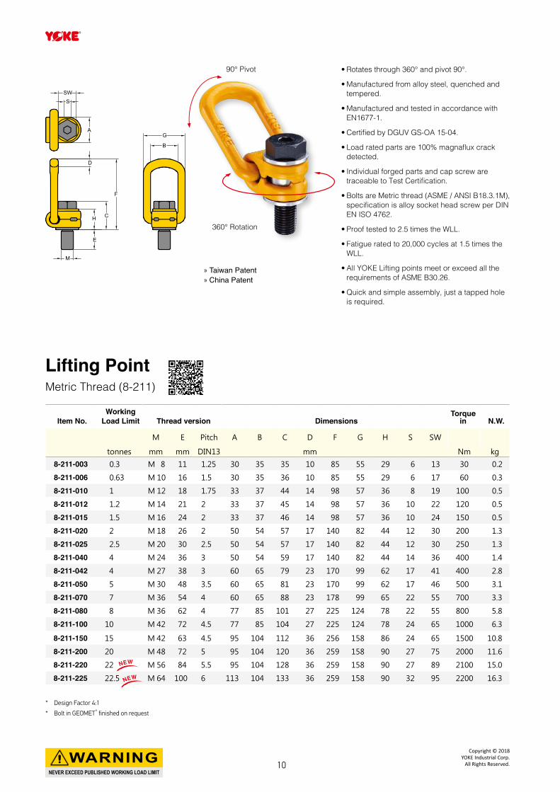
Lifting PointMetric Thread (8-211)
* Design Factor 4:1
* Bolt in GEOMET® finished on request
• Rotates through 360° and pivot 90°.
• Manufactured from alloy steel, quenched and tempered.
• Manufactured and tested in accordance with EN1677-1.
• Certified by DGUV GS-OA 15-04.
• Load rated parts are 100% magnaflux crack detected.
• Individual forged parts and cap screw are traceable to Test Certification.
• Bolts are Metric thread (ASME / ANSI B18.3.1M), specification is alloy socket head screw per DIN EN ISO 4762.
• Proof tested to 2.5 times the WLL.
• Fatigue rated to 20,000 cycles at 1.5 times the WLL.
• All YOKE Lifting points meet or exceed all the requirements of ASME B30.26.
• Quick and simple assembly, just a tapped hole is required.
» Taiwan Patent » China Patent
Item No.Working
Load Limit Thread version DimensionsTorque
in N.W.
M E Pitch A B C D F G H S SW
tonnes mm mm DIN13 mm Nm kg
8-211-003 0.3 M 8 11 1.25 30 35 35 10 85 55 29 6 13 30 0.2
8-211-006 0.63 M 10 16 1.5 30 35 36 10 85 55 29 6 17 60 0.3
8-211-010 1 M 12 18 1.75 33 37 44 14 98 57 36 8 19 100 0.5
8-211-012 1.2 M 14 21 2 33 37 45 14 98 57 36 10 22 120 0.5
8-211-015 1.5 M 16 24 2 33 37 46 14 98 57 36 10 24 150 0.5
8-211-020 2 M 18 26 2 50 54 57 17 140 82 44 12 30 200 1.3
8-211-025 2.5 M 20 30 2.5 50 54 57 17 140 82 44 12 30 250 1.3
8-211-040 4 M 24 36 3 50 54 59 17 140 82 44 14 36 400 1.4
8-211-042 4 M 27 38 3 60 65 79 23 170 99 62 17 41 400 2.8
8-211-050 5 M 30 48 3.5 60 65 81 23 170 99 62 17 46 500 3.1
8-211-070 7 M 36 54 4 60 65 88 23 178 99 65 22 55 700 3.3
8-211-080 8 M 36 62 4 77 85 101 27 225 124 78 22 55 800 5.8
8-211-100 10 M 42 72 4.5 77 85 104 27 225 124 78 24 65 1000 6.3
8-211-150 15 M 42 63 4.5 95 104 112 36 256 158 86 24 65 1500 10.8
8-211-200 20 M 48 72 5 95 104 120 36 259 158 90 27 75 2000 11.6
8-211-220 22 M 56 84 5.5 95 104 128 36 259 158 90 27 89 2100 15.0
8-211-225 22.5 M 64 100 6 113 104 133 36 259 158 90 32 95 2200 16.3
NEW
NEW
90° Pivot
NEVER EXCEED PUBLISHED WORKING LOAD LIMIT
WARNINGCopyright © 2018
YOKE Industrial Corp.All Rights Reserved.10
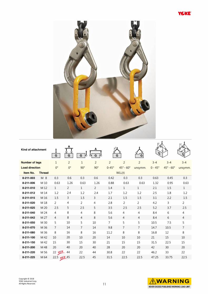
Kind of attachment
Number of legs 1 2 1 2 2 2 2 3-4 3-4 3-4
Load direction 0° 0° 90° 90° 0-45° 45° - 60° unsymm. 0 - 45° 45° - 60° unsymm.
Item No. Thread WLL(t)
8-211-003 M 8 0.3 0.6 0.3 0.6 0.42 0.3 0.3 0.63 0.45 0.3
8-211-006 M 10 0.63 1.26 0.63 1.26 0.88 0.63 0.63 1.32 0.95 0.63
8-211-010 M 12 1 2 1 2 1.4 1 1 2.1 1.5 1
8-211-012 M 14 1.2 2.4 1.2 2.4 1.7 1.2 1.2 2.5 1.8 1.2
8-211-015 M 16 1.5 3 1.5 3 2.1 1.5 1.5 3.1 2.2 1.5
8-211-020 M 18 2 4 2 4 2.8 2 2 4.2 3 2
8-211-025 M 20 2.5 5 2.5 5 3.5 2.5 2.5 5.2 3.7 2.5
8-211-040 M 24 4 8 4 8 5.6 4 4 8.4 6 4
8-211-042 M 27 4 8 4 8 5.6 4 4 8.4 6 4
8-211-050 M 30 5 10 5 10 7 5 5 10.5 7.5 5
8-211-070 M 36 7 14 7 14 9.8 7 7 14.7 10.5 7
8-211-080 M 36 8 16 8 16 11.2 8 8 16.8 12 8
8-211-100 M 42 10 20 10 20 14 10 10 21 15 10
8-211-150 M 42 15 30 15 30 21 15 15 31.5 22.5 15
8-211-200 M 48 20 40 20 40 28 20 20 42 30 20
8-211-220 M 56 22 44 22 44 30.8 22 22 46.2 33 22
8-211-225 M 64 22.5 45 22.5 45 31.5 22.5 22.5 47.25 33.75 22.5
NEW
NEW
NEVER EXCEED PUBLISHED WORKING LOAD LIMIT
WARNINGCopyright © 2018 YOKE Industrial Corp.All Rights Reserved. 11
E
M
H C
F
A
D
G
B
SSW
360° Rotation
90° Pivot
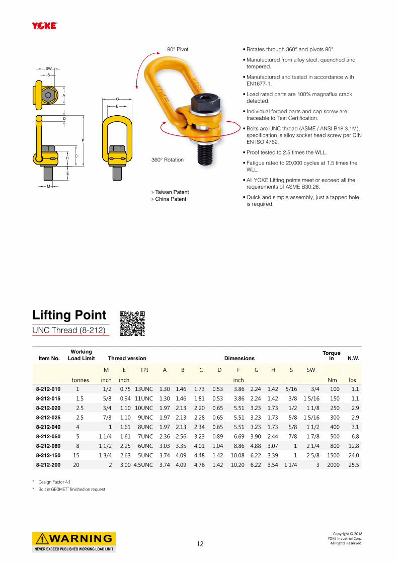
Lifting PointUNC Thread (8-212)
* Design Factor 4:1
* Bolt in GEOMET® finished on request
• Rotates through 360° and pivots 90°.
• Manufactured from alloy steel, quenched and tempered.
• Manufactured and tested in accordance with EN1677-1.
• Load rated parts are 100% magnaflux crack detected.
• Individual forged parts and cap screw are traceable to Test Certification.
• Bolts are UNC thread (ASME / ANSI B18.3.1M), specification is alloy socket head screw per DIN EN ISO 4762.
• Proof tested to 2.5 times the WLL.
• Fatigue rated to 20,000 cycles at 1.5 times the WLL.
• All YOKE Lifting points meet or exceed all the requirements of ASME B30.26.
• Quick and simple assembly, just a tapped hole is required.
Item No.Working
Load Limit Thread version DimensionsTorque
in N.W.
M E TPI A B C D F G H S SW
tonnes inch inch inch Nm lbs
8-212-010 1 1/2 0.75 13UNC 1.30 1.46 1.73 0.53 3.86 2.24 1.42 5/16 3/4 100 1.1
8-212-015 1.5 5/8 0.94 11UNC 1.30 1.46 1.81 0.53 3.86 2.24 1.42 3/8 1 5/16 150 1.1
8-212-020 2.5 3/4 1.10 10UNC 1.97 2.13 2.20 0.65 5.51 3.23 1.73 1/2 1 1/8 250 2.9
8-212-025 2.5 7/8 1.10 9UNC 1.97 2.13 2.28 0.65 5.51 3.23 1.73 5/8 1 5/16 300 2.9
8-212-040 4 1 1.61 8UNC 1.97 2.13 2.34 0.65 5.51 3.23 1.73 5/8 1 1/2 400 3.1
8-212-050 5 1 1/4 1.61 7UNC 2.36 2.56 3.23 0.89 6.69 3.90 2.44 7/8 1 7/8 500 6.8
8-212-080 8 1 1/2 2.25 6UNC 3.03 3.35 4.01 1.04 8.86 4.88 3.07 1 2 1/4 800 12.8
8-212-150 15 1 3/4 2.63 5UNC 3.74 4.09 4.48 1.42 10.08 6.22 3.39 1 2 5/8 1500 24.0
8-212-200 20 2 3.00 4.5UNC 3.74 4.09 4.76 1.42 10.20 6.22 3.54 1 1/4 3 2000 25.5
» Taiwan Patent » China Patent
NEVER EXCEED PUBLISHED WORKING LOAD LIMIT
WARNINGCopyright © 2018
YOKE Industrial Corp.All Rights Reserved.12
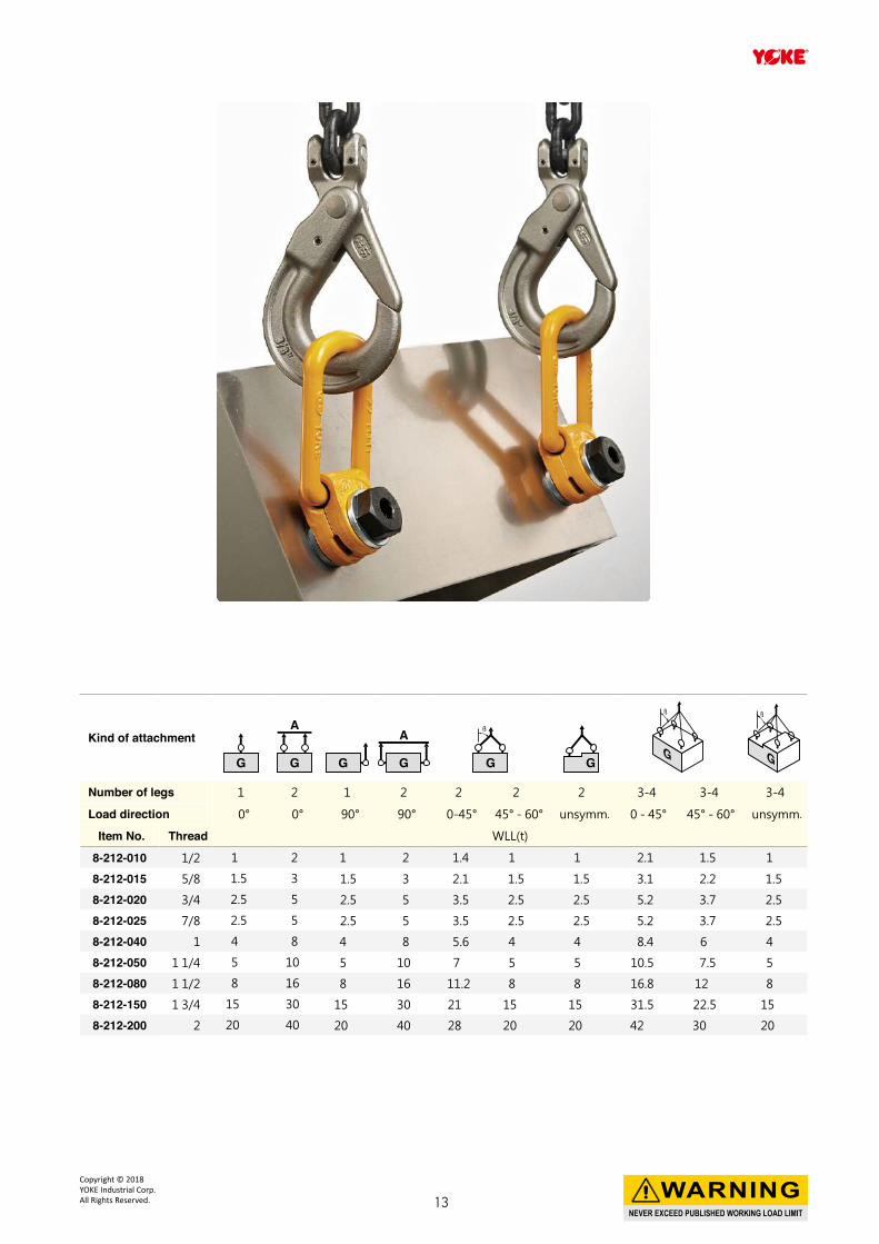
Kind of attachment
Number of legs 1 2 1 2 2 2 2 3-4 3-4 3-4
Load direction 0° 0° 90° 90° 0-45° 45° - 60° unsymm. 0 - 45° 45° - 60° unsymm.
Item No. Thread WLL(t)
8-212-010 1/2 1 2 1 2 1.4 1 1 2.1 1.5 1
8-212-015 5/8 1.5 3 1.5 3 2.1 1.5 1.5 3.1 2.2 1.5
8-212-020 3/4 2.5 5 2.5 5 3.5 2.5 2.5 5.2 3.7 2.5
8-212-025 7/8 2.5 5 2.5 5 3.5 2.5 2.5 5.2 3.7 2.5
8-212-040 1 4 8 4 8 5.6 4 4 8.4 6 4
8-212-050 1 1/4 5 10 5 10 7 5 5 10.5 7.5 5
8-212-080 1 1/2 8 16 8 16 11.2 8 8 16.8 12 8
8-212-150 1 3/4 15 30 15 30 21 15 15 31.5 22.5 15
8-212-200 2 20 40 20 40 28 20 20 42 30 20
NEVER EXCEED PUBLISHED WORKING LOAD LIMIT
WARNINGCopyright © 2018 YOKE Industrial Corp.All Rights Reserved. 13
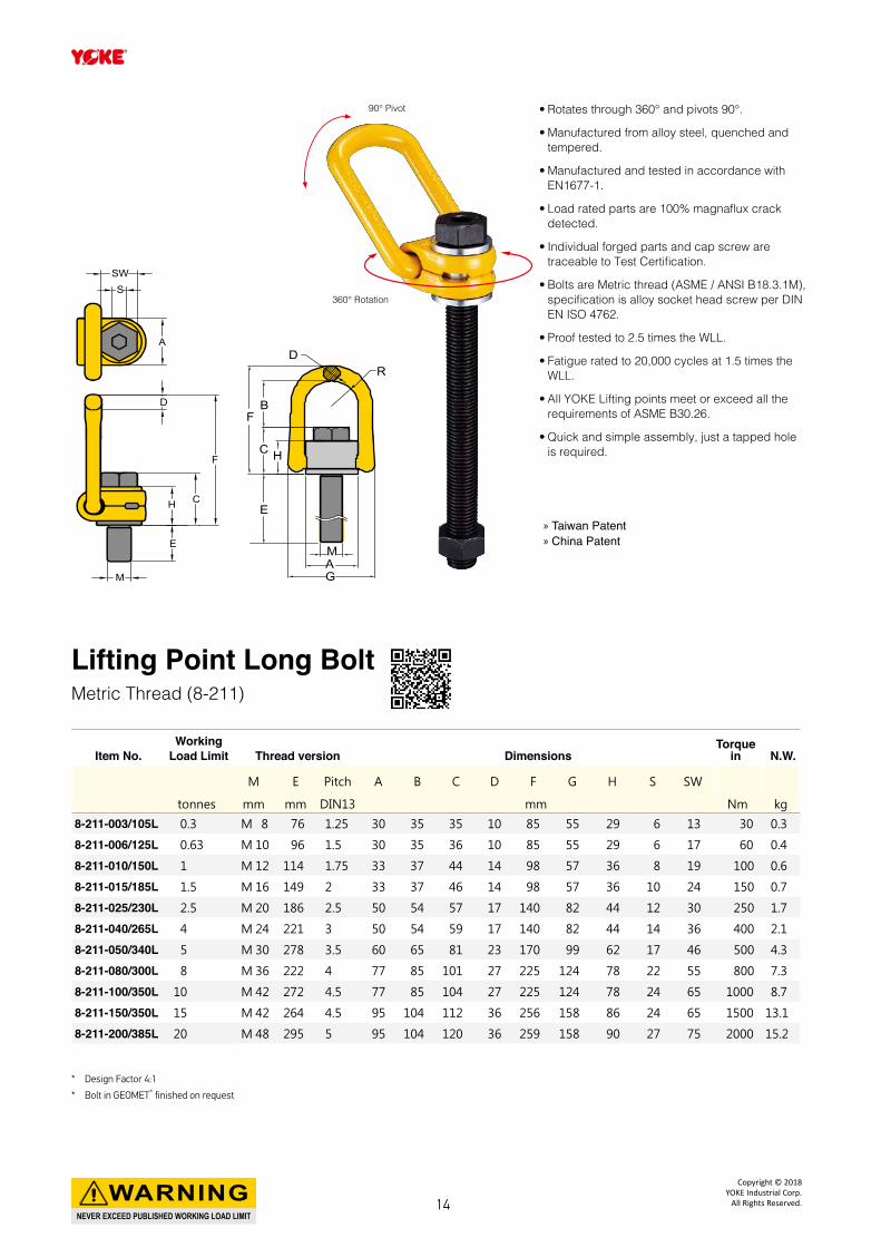
Lifting Point Long BoltMetric Thread (8-211)
* Design Factor 4:1
* Bolt in GEOMET® finished on request
• Rotates through 360° and pivots 90°.
• Manufactured from alloy steel, quenched and tempered.
• Manufactured and tested in accordance with EN1677-1.
• Load rated parts are 100% magnaflux crack detected.
• Individual forged parts and cap screw are traceable to Test Certification.
• Bolts are Metric thread (ASME / ANSI B18.3.1M), specification is alloy socket head screw per DIN EN ISO 4762.
• Proof tested to 2.5 times the WLL.
• Fatigue rated to 20,000 cycles at 1.5 times the WLL.
• All YOKE Lifting points meet or exceed all the requirements of ASME B30.26.
• Quick and simple assembly, just a tapped hole is required.
» Taiwan Patent » China Patent
Item No.Working
Load Limit Thread version DimensionsTorque
in N.W.
M E Pitch A B C D F G H S SW
tonnes mm mm DIN13 mm Nm kg
8-211-003/105L 0.3 M 8 76 1.25 30 35 35 10 85 55 29 6 13 30 0.3
8-211-006/125L 0.63 M 10 96 1.5 30 35 36 10 85 55 29 6 17 60 0.4
8-211-010/150L 1 M 12 114 1.75 33 37 44 14 98 57 36 8 19 100 0.6
8-211-015/185L 1.5 M 16 149 2 33 37 46 14 98 57 36 10 24 150 0.7
8-211-025/230L 2.5 M 20 186 2.5 50 54 57 17 140 82 44 12 30 250 1.7
8-211-040/265L 4 M 24 221 3 50 54 59 17 140 82 44 14 36 400 2.1
8-211-050/340L 5 M 30 278 3.5 60 65 81 23 170 99 62 17 46 500 4.3
8-211-080/300L 8 M 36 222 4 77 85 101 27 225 124 78 22 55 800 7.3
8-211-100/350L 10 M 42 272 4.5 77 85 104 27 225 124 78 24 65 1000 8.7
8-211-150/350L 15 M 42 264 4.5 95 104 112 36 256 158 86 24 65 1500 13.1
8-211-200/385L 20 M 48 295 5 95 104 120 36 259 158 90 27 75 2000 15.2
E
C
FB
RD
H
MAG
E
M
H C
F
A
D
SSW
90° Pivot
360° Rotation
NEVER EXCEED PUBLISHED WORKING LOAD LIMIT
WARNINGCopyright © 2018
YOKE Industrial Corp.All Rights Reserved.14
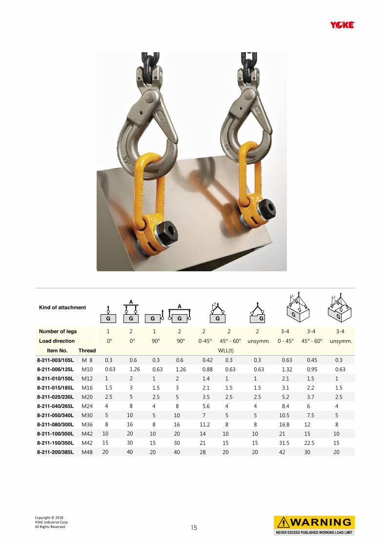
Kind of attachment
Number of legs 1 2 1 2 2 2 2 3-4 3-4 3-4
Load direction 0° 0° 90° 90° 0-45° 45° - 60° unsymm. 0 - 45° 45° - 60° unsymm.
Item No. Thread WLL(t)
8-211-003/105L M 8 0.3 0.6 0.3 0.6 0.42 0.3 0.3 0.63 0.45 0.3
8-211-006/125L M10 0.63 1.26 0.63 1.26 0.88 0.63 0.63 1.32 0.95 0.63
8-211-010/150L M12 1 2 1 2 1.4 1 1 2.1 1.5 1
8-211-015/185L M16 1.5 3 1.5 3 2.1 1.5 1.5 3.1 2.2 1.5
8-211-025/230L M20 2.5 5 2.5 5 3.5 2.5 2.5 5.2 3.7 2.5
8-211-040/265L M24 4 8 4 8 5.6 4 4 8.4 6 4
8-211-050/340L M30 5 10 5 10 7 5 5 10.5 7.5 5
8-211-080/300L M36 8 16 8 16 11.2 8 8 16.8 12 8
8-211-100/350L M42 10 20 10 20 14 10 10 21 15 10
8-211-150/350L M42 15 30 15 30 21 15 15 31.5 22.5 15
8-211-200/385L M48 20 40 20 40 28 20 20 42 30 20
NEVER EXCEED PUBLISHED WORKING LOAD LIMIT
WARNINGCopyright © 2018 YOKE Industrial Corp.All Rights Reserved. 15
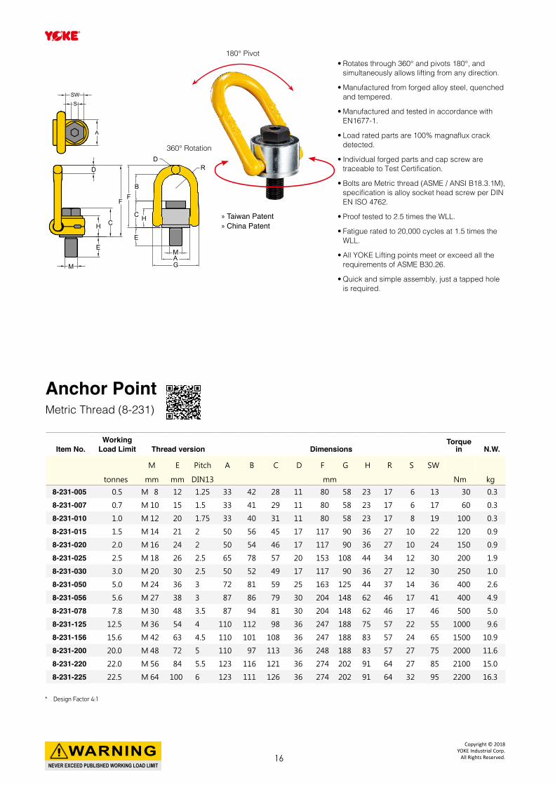
180° Pivot
» Taiwan Patent » China Patent
360° Rotation
• Rotates through 360° and pivots 180°, and simultaneously allows lifting from any direction.
• Manufactured from forged alloy steel, quenched and tempered.
• Manufactured and tested in accordance with EN1677-1.
• Load rated parts are 100% magnaflux crack detected.
• Individual forged parts and cap screw are traceable to Test Certification.
• Bolts are Metric thread (ASME / ANSI B18.3.1M), specification is alloy socket head screw per DIN EN ISO 4762.
• Proof tested to 2.5 times the WLL.
• Fatigue rated to 20,000 cycles at 1.5 times the WLL.
• All YOKE Lifting points meet or exceed all the requirements of ASME B30.26.
• Quick and simple assembly, just a tapped hole is required.
Anchor PointMetric Thread (8-231)
Item No.Working
Load Limit Thread version DimensionsTorque
in N.W.
M E Pitch A B C D F G H R S SW
tonnes mm mm DIN13 mm Nm kg
8-231-005 0.5 M 8 12 1.25 33 42 28 11 80 58 23 17 6 13 30 0.3
8-231-007 0.7 M 10 15 1.5 33 41 29 11 80 58 23 17 6 17 60 0.3
8-231-010 1.0 M 12 20 1.75 33 40 31 11 80 58 23 17 8 19 100 0.3
8-231-015 1.5 M 14 21 2 50 56 45 17 117 90 36 27 10 22 120 0.9
8-231-020 2.0 M 16 24 2 50 54 46 17 117 90 36 27 10 24 150 0.9
8-231-025 2.5 M 18 26 2.5 65 78 57 20 153 108 44 34 12 30 200 1.9
8-231-030 3.0 M 20 30 2.5 50 52 49 17 117 90 36 27 12 30 250 1.0
8-231-050 5.0 M 24 36 3 72 81 59 25 163 125 44 37 14 36 400 2.6
8-231-056 5.6 M 27 38 3 87 86 79 30 204 148 62 46 17 41 400 4.9
8-231-078 7.8 M 30 48 3.5 87 94 81 30 204 148 62 46 17 46 500 5.0
8-231-125 12.5 M 36 54 4 110 112 98 36 247 188 75 57 22 55 1000 9.6
8-231-156 15.6 M 42 63 4.5 110 101 108 36 247 188 83 57 24 65 1500 10.9
8-231-200 20.0 M 48 72 5 110 97 113 36 248 188 83 57 27 75 2000 11.6
8-231-220 22.0 M 56 84 5.5 123 116 121 36 274 202 91 64 27 85 2100 15.0
8-231-225 22.5 M 64 100 6 123 111 126 36 274 202 91 64 32 95 2200 16.3
RD
BF
C
E
H
MAG
E
M
H C
F
D
A
SSW
* Design Factor 4:1
NEVER EXCEED PUBLISHED WORKING LOAD LIMIT
WARNINGCopyright © 2018
YOKE Industrial Corp.All Rights Reserved.16
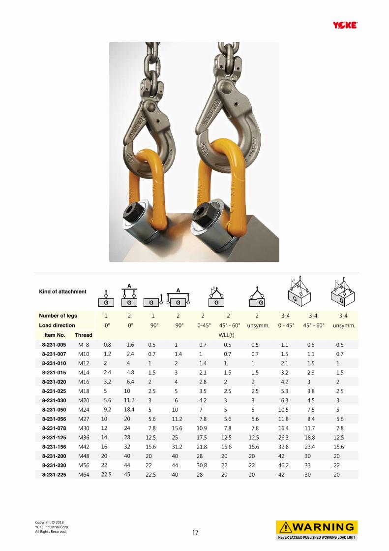
Kind of attachment
Number of legs 1 2 1 2 2 2 2 3-4 3-4 3-4
Load direction 0° 0° 90° 90° 0-45° 45° - 60° unsymm. 0 - 45° 45° - 60° unsymm.
Item No. Thread WLL(t)
8-231-005 M 8 0.8 1.6 0.5 1 0.7 0.5 0.5 1.1 0.8 0.5
8-231-007 M10 1.2 2.4 0.7 1.4 1 0.7 0.7 1.5 1.1 0.7
8-231-010 M12 2 4 1 2 1.4 1 1 2.1 1.5 1
8-231-015 M14 2.4 4.8 1.5 3 2.1 1.5 1.5 3.2 2.3 1.5
8-231-020 M16 3.2 6.4 2 4 2.8 2 2 4.2 3 2
8-231-025 M18 5 10 2.5 5 3.5 2.5 2.5 5.3 3.8 2.5
8-231-030 M20 5.6 11.2 3 6 4.2 3 3 6.3 4.5 3
8-231-050 M24 9.2 18.4 5 10 7 5 5 10.5 7.5 5
8-231-056 M27 10 20 5.6 11.2 7.8 5.6 5.6 11.8 8.4 5.6
8-231-078 M30 12 24 7.8 15.6 10.9 7.8 7.8 16.4 11.7 7.8
8-231-125 M36 14 28 12.5 25 17.5 12.5 12.5 26.3 18.8 12.5
8-231-156 M42 16 32 15.6 31.2 21.8 15.6 15.6 32.8 23.4 15.6
8-231-200 M48 20 40 20 40 28 20 20 42 30 20
8-231-220 M56 22 44 22 44 30.8 22 22 46.2 33 22
8-231-225 M64 22.5 45 22.5 40 28 20 20 42 30 20
NEVER EXCEED PUBLISHED WORKING LOAD LIMIT
WARNINGCopyright © 2018 YOKE Industrial Corp.All Rights Reserved. 17
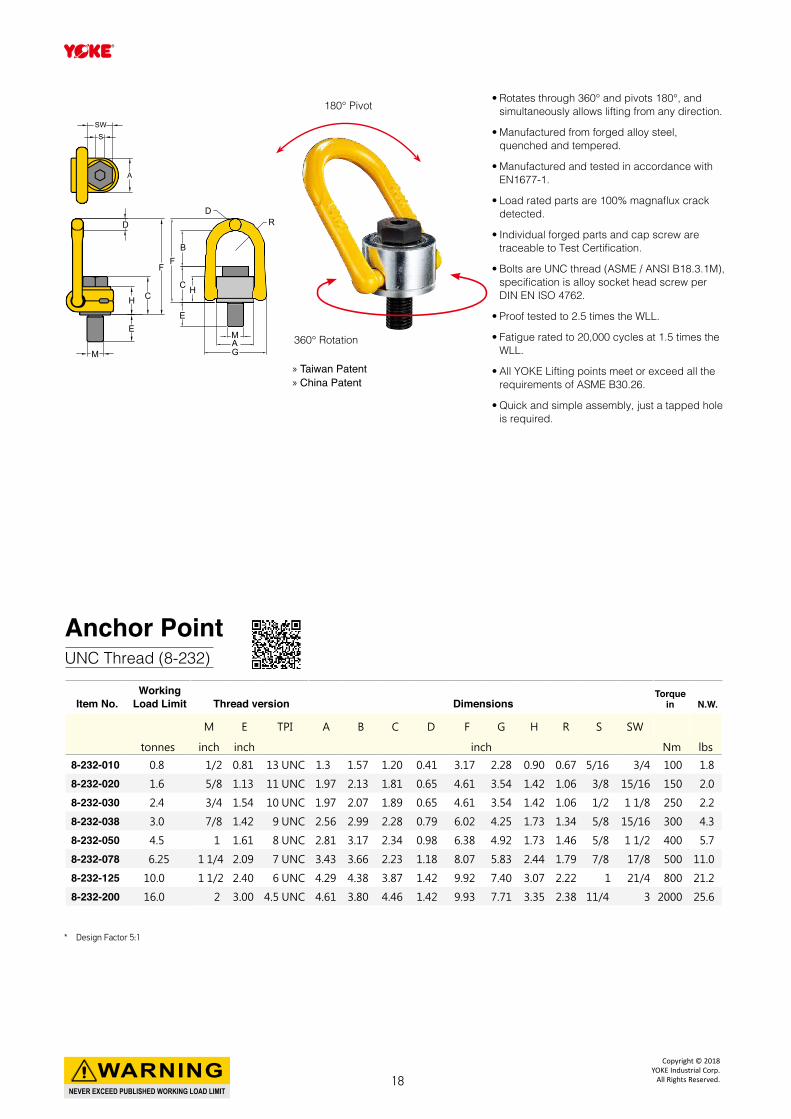
180° Pivot
» Taiwan Patent » China Patent
360° Rotation
• Rotates through 360° and pivots 180°, and simultaneously allows lifting from any direction.
• Manufactured from forged alloy steel, quenched and tempered.
• Manufactured and tested in accordance with EN1677-1.
• Load rated parts are 100% magnaflux crack detected.
• Individual forged parts and cap screw are traceable to Test Certification.
• Bolts are UNC thread (ASME / ANSI B18.3.1M), specification is alloy socket head screw per DIN EN ISO 4762.
• Proof tested to 2.5 times the WLL.
• Fatigue rated to 20,000 cycles at 1.5 times the WLL.
• All YOKE Lifting points meet or exceed all the requirements of ASME B30.26.
• Quick and simple assembly, just a tapped hole is required.
Anchor PointUNC Thread (8-232)
Item No.Working
Load Limit Thread version DimensionsTorque
in N.W.
M E TPI A B C D F G H R S SW
tonnes inch inch inch Nm lbs
8-232-010 0.8 1/2 0.81 13 UNC 1.3 1.57 1.20 0.41 3.17 2.28 0.90 0.67 5/16 3/4 100 1.8
8-232-020 1.6 5/8 1.13 11 UNC 1.97 2.13 1.81 0.65 4.61 3.54 1.42 1.06 3/8 15/16 150 2.0
8-232-030 2.4 3/4 1.54 10 UNC 1.97 2.07 1.89 0.65 4.61 3.54 1.42 1.06 1/2 1 1/8 250 2.2
8-232-038 3.0 7/8 1.42 9 UNC 2.56 2.99 2.28 0.79 6.02 4.25 1.73 1.34 5/8 15/16 300 4.3
8-232-050 4.5 1 1.61 8 UNC 2.81 3.17 2.34 0.98 6.38 4.92 1.73 1.46 5/8 1 1/2 400 5.7
8-232-078 6.25 1 1/4 2.09 7 UNC 3.43 3.66 2.23 1.18 8.07 5.83 2.44 1.79 7/8 17/8 500 11.0
8-232-125 10.0 1 1/2 2.40 6 UNC 4.29 4.38 3.87 1.42 9.92 7.40 3.07 2.22 1 21/4 800 21.2
8-232-200 16.0 2 3.00 4.5 UNC 4.61 3.80 4.46 1.42 9.93 7.71 3.35 2.38 11/4 3 2000 25.6
RD
BF
C
E
H
MAG
E
M
H C
F
D
A
SSW
* Design Factor 5:1
NEVER EXCEED PUBLISHED WORKING LOAD LIMIT
WARNINGCopyright © 2018
YOKE Industrial Corp.All Rights Reserved.18
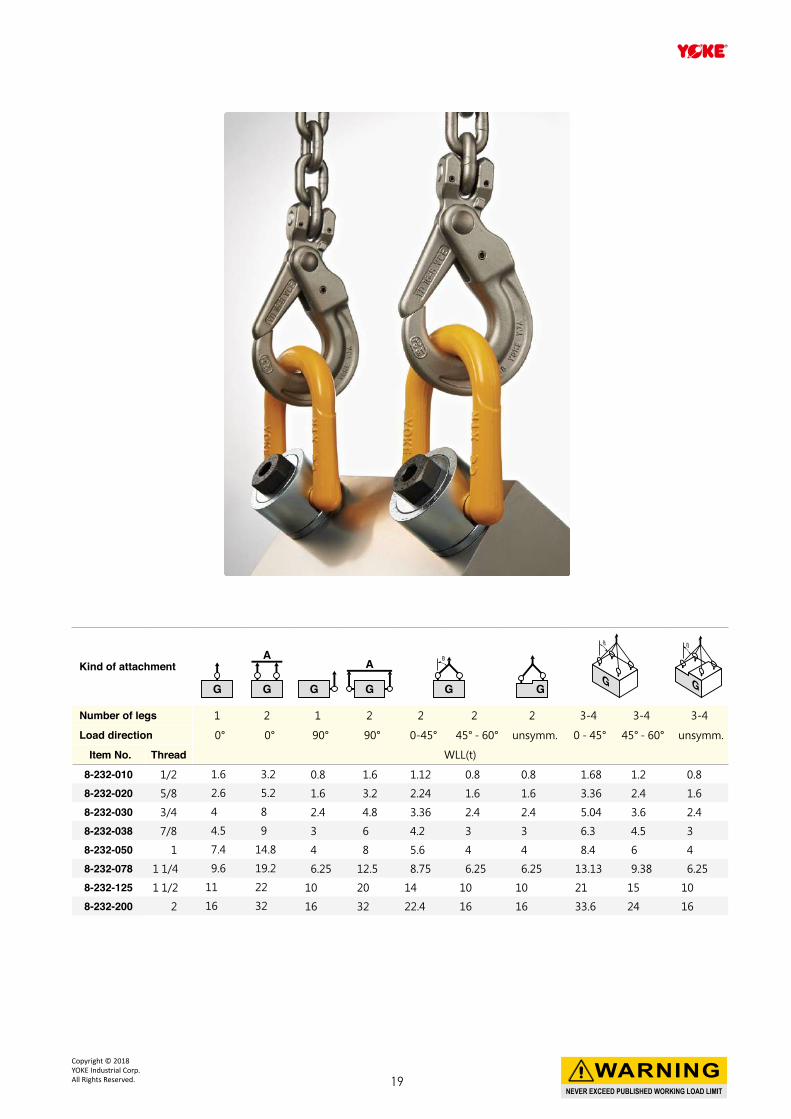
Kind of attachment
Number of legs 1 2 1 2 2 2 2 3-4 3-4 3-4
Load direction 0° 0° 90° 90° 0-45° 45° - 60° unsymm. 0 - 45° 45° - 60° unsymm.
Item No. Thread WLL(t)
8-232-010 1/2 1.6 3.2 0.8 1.6 1.12 0.8 0.8 1.68 1.2 0.8
8-232-020 5/8 2.6 5.2 1.6 3.2 2.24 1.6 1.6 3.36 2.4 1.6
8-232-030 3/4 4 8 2.4 4.8 3.36 2.4 2.4 5.04 3.6 2.4
8-232-038 7/8 4.5 9 3 6 4.2 3 3 6.3 4.5 3
8-232-050 1 7.4 14.8 4 8 5.6 4 4 8.4 6 4
8-232-078 1 1/4 9.6 19.2 6.25 12.5 8.75 6.25 6.25 13.13 9.38 6.25
8-232-125 1 1/2 11 22 10 20 14 10 10 21 15 10
8-232-200 2 16 32 16 32 22.4 16 16 33.6 24 16
NEVER EXCEED PUBLISHED WORKING LOAD LIMIT
WARNINGCopyright © 2018 YOKE Industrial Corp.All Rights Reserved. 19
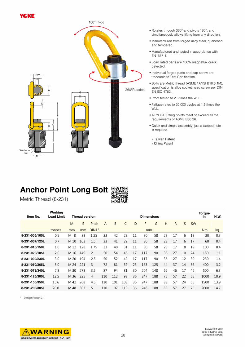
» Taiwan Patent » China Patent
• Rotates through 360° and pivots 180°, and simultaneously allows lifting from any direction.
• Manufactured from forged alloy steel, quenched and tempered.
• Manufactured and tested in accordance with EN1677-1.
• Load rated parts are 100% magnaflux crack detected.
• Individual forged parts and cap screw are traceable to Test Certification.
• Bolts are Metric thread (ASME / ANSI B18.3.1M), specification is alloy socket head screw per DIN EN ISO 4762.
• Proof tested to 2.5 times the WLL.
• Fatigue rated to 20,000 cycles at 1.5 times the WLL.
• All YOKE Lifting points meet or exceed all the requirements of ASME B30.26.
• Quick and simple assembly, just a tapped hole is required.
Anchor Point Long BoltMetric Thread (8-231)
Item No.Working
Load Limit Thread version DimensionsTorque
in N.W.
M E Pitch A B C D F G H R S SW
tonnes mm mm DIN13 mm Nm kg
8-231-005/105L 0.5 M 8 83 1.25 33 42 28 11 80 58 23 17 6 13 30 0.3
8-231-007/125L 0.7 M 10 103 1.5 33 41 29 11 80 58 23 17 6 17 60 0.4
8-231-010/150L 1.0 M 12 128 1.75 33 40 31 11 80 58 23 17 8 19 100 0.4
8-231-020/185L 2.0 M 16 149 2 50 54 46 17 117 90 36 27 10 24 150 1.1
8-231-030/230L 3.0 M 20 194 2.5 50 52 49 17 117 90 36 27 12 30 250 1.4
8-231-050/265L 5.0 M 24 221 3 72 81 59 25 163 125 44 37 14 36 400 3.2
8-231-078/340L 7.8 M 30 278 3.5 87 94 81 30 204 148 62 46 17 46 500 6.3
8-231-125/300L 12.5 M 36 225 4 110 112 98 36 247 188 75 57 22 55 1000 10.9
8-231-156/350L 15.6 M 42 268 4.5 110 101 108 36 247 188 83 57 24 65 1500 13.9
8-231-200/385L 20.0 M 48 303 5 110 97 113 36 248 188 83 57 27 75 2000 14.7
MM
EE
HH
DD
CC
FF
AA
SSSWSW
GGBB
180° Pivot
360°Rotation
* Design Factor 4:1
NEVER EXCEED PUBLISHED WORKING LOAD LIMIT
WARNINGCopyright © 2018
YOKE Industrial Corp.All Rights Reserved.20
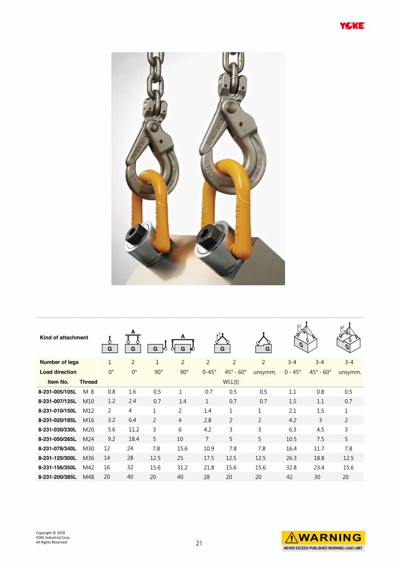
Kind of attachment
Number of legs 1 2 1 2 2 2 2 3-4 3-4 3-4
Load direction 0° 0° 90° 90° 0-45° 45° - 60° unsymm. 0 - 45° 45° - 60° unsymm.
Item No. Thread WLL(t)
8-231-005/105L M 8 0.8 1.6 0.5 1 0.7 0.5 0.5 1.1 0.8 0.5
8-231-007/125L M10 1.2 2.4 0.7 1.4 1 0.7 0.7 1.5 1.1 0.7
8-231-010/150L M12 2 4 1 2 1.4 1 1 2.1 1.5 1
8-231-020/185L M16 3.2 6.4 2 4 2.8 2 2 4.2 3 2
8-231-030/230L M20 5.6 11.2 3 6 4.2 3 3 6.3 4.5 3
8-231-050/265L M24 9.2 18.4 5 10 7 5 5 10.5 7.5 5
8-231-078/340L M30 12 24 7.8 15.6 10.9 7.8 7.8 16.4 11.7 7.8
8-231-125/300L M36 14 28 12.5 25 17.5 12.5 12.5 26.3 18.8 12.5
8-231-156/350L M42 16 32 15.6 31.2 21.8 15.6 15.6 32.8 23.4 15.6
8-231-200/385L M48 20 40 20 40 28 20 20 42 30 20
NEVER EXCEED PUBLISHED WORKING LOAD LIMIT
WARNINGCopyright © 2018 YOKE Industrial Corp.All Rights Reserved. 21
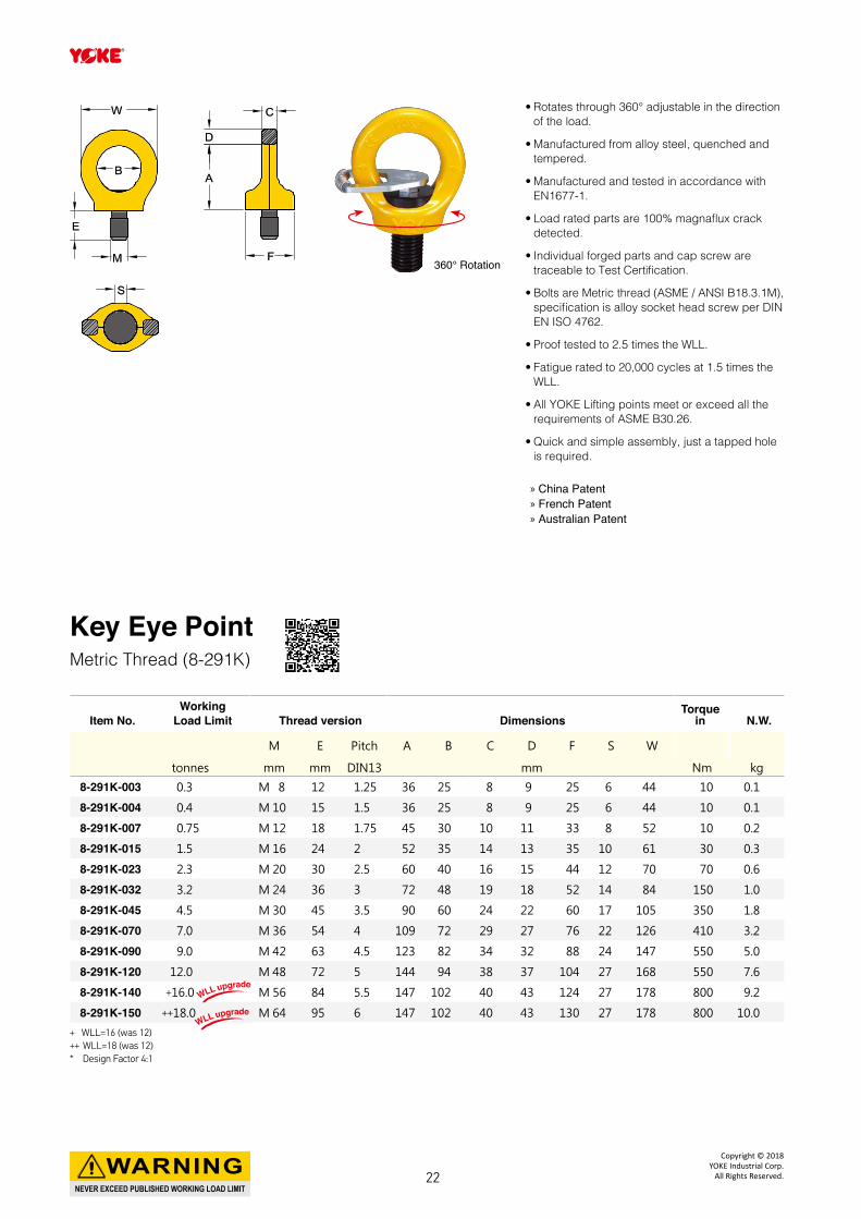
• Rotates through 360° adjustable in the direction of the load.
• Manufactured from alloy steel, quenched and tempered.
• Manufactured and tested in accordance with EN1677-1.
• Load rated parts are 100% magnaflux crack detected.
• Individual forged parts and cap screw are traceable to Test Certification.
• Bolts are Metric thread (ASME / ANSI B18.3.1M), specification is alloy socket head screw per DIN EN ISO 4762.
• Proof tested to 2.5 times the WLL.
• Fatigue rated to 20,000 cycles at 1.5 times the WLL.
• All YOKE Lifting points meet or exceed all the requirements of ASME B30.26.
• Quick and simple assembly, just a tapped hole is required.
Key Eye PointMetric Thread (8-291K)
+ WLL=16 (was 12)++ WLL=18 (was 12)* Design Factor 4:1
Item No.Working
Load Limit Thread version DimensionsTorque
in N.W.
M E Pitch A B C D F S W
tonnes mm mm DIN13 mm Nm kg
8-291K-003 0.3 M 8 12 1.25 36 25 8 9 25 6 44 10 0.1
8-291K-004 0.4 M 10 15 1.5 36 25 8 9 25 6 44 10 0.1
8-291K-007 0.75 M 12 18 1.75 45 30 10 11 33 8 52 10 0.2
8-291K-015 1.5 M 16 24 2 52 35 14 13 35 10 61 30 0.3
8-291K-023 2.3 M 20 30 2.5 60 40 16 15 44 12 70 70 0.6
8-291K-032 3.2 M 24 36 3 72 48 19 18 52 14 84 150 1.0
8-291K-045 4.5 M 30 45 3.5 90 60 24 22 60 17 105 350 1.8
8-291K-070 7.0 M 36 54 4 109 72 29 27 76 22 126 410 3.2
8-291K-090 9.0 M 42 63 4.5 123 82 34 32 88 24 147 550 5.0
8-291K-120 12.0 M 48 72 5 144 94 38 37 104 27 168 550 7.6
8-291K-140 +16.0 M 56 84 5.5 147 102 40 43 124 27 178 800 9.2
8-291K-150 ++18.0 M 64 95 6 147 102 40 43 130 27 178 800 10.0
360° Rotation
CC
DD
AA
FF
EE
MM
BB
WW
SS
» China Patent » French Patent » Australian Patent
WLL upgrade
WLL upgrade
NEVER EXCEED PUBLISHED WORKING LOAD LIMIT
WARNINGCopyright © 2018
YOKE Industrial Corp.All Rights Reserved.22
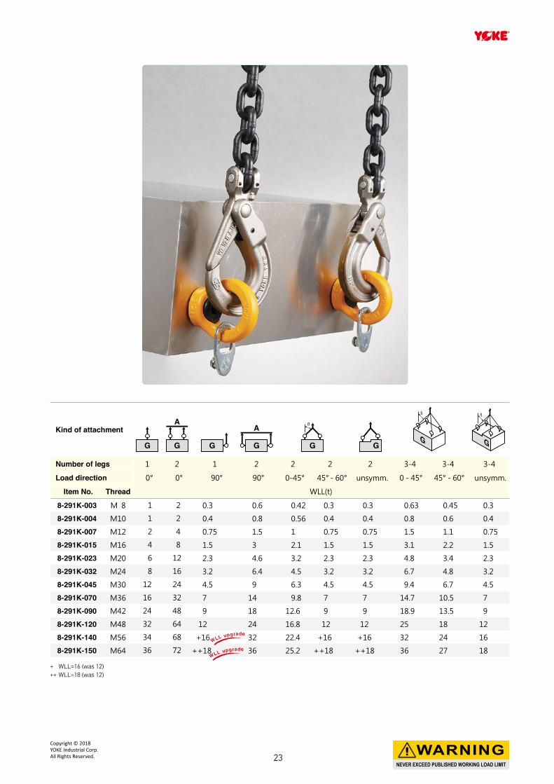
+ WLL=16 (was 12)++ WLL=18 (was 12)
Kind of attachment
Number of legs 1 2 1 2 2 2 2 3-4 3-4 3-4
Load direction 0° 0° 90° 90° 0-45° 45° - 60° unsymm. 0 - 45° 45° - 60° unsymm.
Item No. Thread WLL(t)
8-291K-003 M 8 1 2 0.3 0.6 0.42 0.3 0.3 0.63 0.45 0.3
8-291K-004 M10 1 2 0.4 0.8 0.56 0.4 0.4 0.8 0.6 0.4
8-291K-007 M12 2 4 0.75 1.5 1 0.75 0.75 1.5 1.1 0.75
8-291K-015 M16 4 8 1.5 3 2.1 1.5 1.5 3.1 2.2 1.5
8-291K-023 M20 6 12 2.3 4.6 3.2 2.3 2.3 4.8 3.4 2.3
8-291K-032 M24 8 16 3.2 6.4 4.5 3.2 3.2 6.7 4.8 3.2
8-291K-045 M30 12 24 4.5 9 6.3 4.5 4.5 9.4 6.7 4.5
8-291K-070 M36 16 32 7 14 9.8 7 7 14.7 10.5 7
8-291K-090 M42 24 48 9 18 12.6 9 9 18.9 13.5 9
8-291K-120 M48 32 64 12 24 16.8 12 12 25 18 12
8-291K-140 M56 34 68 +16 32 22.4 +16 +16 32 24 16
8-291K-150 M64 36 72 ++18 36 25.2 ++18 ++18 36 27 18WLL upgrade
WLL upgrade
NEVER EXCEED PUBLISHED WORKING LOAD LIMIT
WARNINGCopyright © 2018 YOKE Industrial Corp.All Rights Reserved. 23
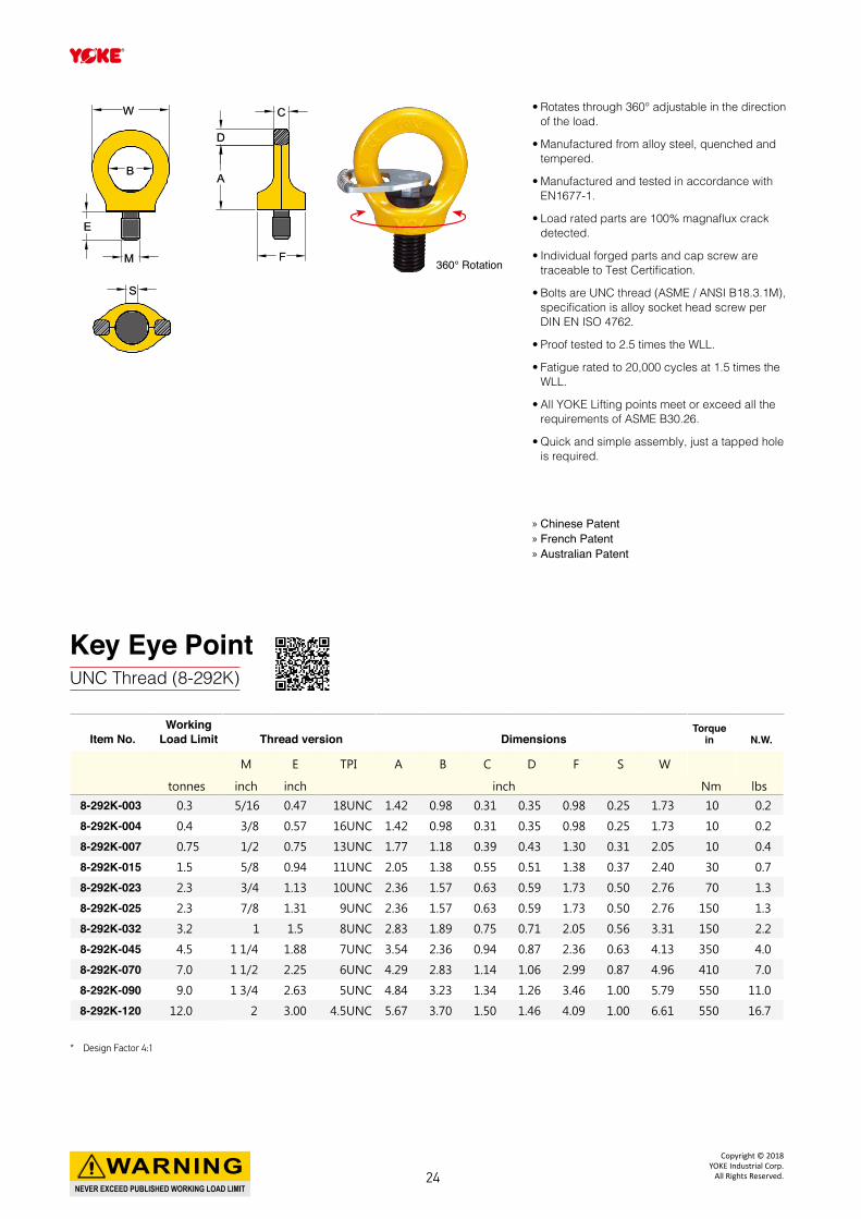
• Rotates through 360° adjustable in the direction of the load.
• Manufactured from alloy steel, quenched and tempered.
• Manufactured and tested in accordance with EN1677-1.
• Load rated parts are 100% magnaflux crack detected.
• Individual forged parts and cap screw are traceable to Test Certification.
• Bolts are UNC thread (ASME / ANSI B18.3.1M), specification is alloy socket head screw per DIN EN ISO 4762.
• Proof tested to 2.5 times the WLL.
• Fatigue rated to 20,000 cycles at 1.5 times the WLL.
• All YOKE Lifting points meet or exceed all the requirements of ASME B30.26.
• Quick and simple assembly, just a tapped hole is required.
Key Eye PointUNC Thread (8-292K)
360° Rotation
Item No.Working
Load Limit Thread version DimensionsTorque
in N.W.
M E TPI A B C D F S W
tonnes inch inch inch Nm lbs
8-292K-003 0.3 5/16 0.47 18UNC 1.42 0.98 0.31 0.35 0.98 0.25 1.73 10 0.2
8-292K-004 0.4 3/8 0.57 16UNC 1.42 0.98 0.31 0.35 0.98 0.25 1.73 10 0.2
8-292K-007 0.75 1/2 0.75 13UNC 1.77 1.18 0.39 0.43 1.30 0.31 2.05 10 0.4
8-292K-015 1.5 5/8 0.94 11UNC 2.05 1.38 0.55 0.51 1.38 0.37 2.40 30 0.7
8-292K-023 2.3 3/4 1.13 10UNC 2.36 1.57 0.63 0.59 1.73 0.50 2.76 70 1.3
8-292K-025 2.3 7/8 1.31 9UNC 2.36 1.57 0.63 0.59 1.73 0.50 2.76 150 1.3
8-292K-032 3.2 1 1.5 8UNC 2.83 1.89 0.75 0.71 2.05 0.56 3.31 150 2.2
8-292K-045 4.5 1 1/4 1.88 7UNC 3.54 2.36 0.94 0.87 2.36 0.63 4.13 350 4.0
8-292K-070 7.0 1 1/2 2.25 6UNC 4.29 2.83 1.14 1.06 2.99 0.87 4.96 410 7.0
8-292K-090 9.0 1 3/4 2.63 5UNC 4.84 3.23 1.34 1.26 3.46 1.00 5.79 550 11.0
8-292K-120 12.0 2 3.00 4.5UNC 5.67 3.70 1.50 1.46 4.09 1.00 6.61 550 16.7
CC
DD
AA
FF
EE
MM
BB
WW
SS
» Chinese Patent » French Patent » Australian Patent
* Design Factor 4:1
NEVER EXCEED PUBLISHED WORKING LOAD LIMIT
WARNINGCopyright © 2018
YOKE Industrial Corp.All Rights Reserved.24
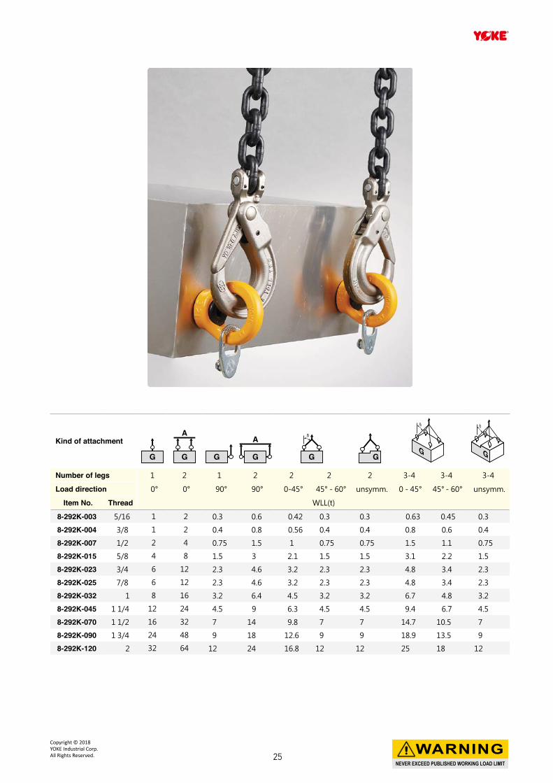
Kind of attachment
Number of legs 1 2 1 2 2 2 2 3-4 3-4 3-4
Load direction 0° 0° 90° 90° 0-45° 45° - 60° unsymm. 0 - 45° 45° - 60° unsymm.
Item No. Thread WLL(t)
8-292K-003 5/16 1 2 0.3 0.6 0.42 0.3 0.3 0.63 0.45 0.3
8-292K-004 3/8 1 2 0.4 0.8 0.56 0.4 0.4 0.8 0.6 0.4
8-292K-007 1/2 2 4 0.75 1.5 1 0.75 0.75 1.5 1.1 0.75
8-292K-015 5/8 4 8 1.5 3 2.1 1.5 1.5 3.1 2.2 1.5
8-292K-023 3/4 6 12 2.3 4.6 3.2 2.3 2.3 4.8 3.4 2.3
8-292K-025 7/8 6 12 2.3 4.6 3.2 2.3 2.3 4.8 3.4 2.3
8-292K-032 1 8 16 3.2 6.4 4.5 3.2 3.2 6.7 4.8 3.2
8-292K-045 1 1/4 12 24 4.5 9 6.3 4.5 4.5 9.4 6.7 4.5
8-292K-070 1 1/2 16 32 7 14 9.8 7 7 14.7 10.5 7
8-292K-090 1 3/4 24 48 9 18 12.6 9 9 18.9 13.5 9
8-292K-120 2 32 64 12 24 16.8 12 12 25 18 12
NEVER EXCEED PUBLISHED WORKING LOAD LIMIT
WARNINGCopyright © 2018 YOKE Industrial Corp.All Rights Reserved. 25
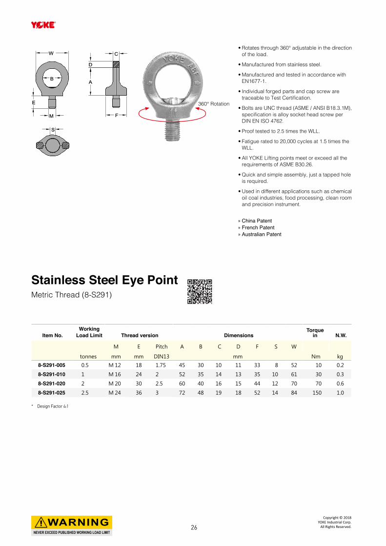
• Rotates through 360° adjustable in the direction of the load.
• Manufactured from stainless steel.
• Manufactured and tested in accordance with EN1677-1.
• Individual forged parts and cap screw are traceable to Test Certification.
• Bolts are UNC thread (ASME / ANSI B18.3.1M), specification is alloy socket head screw per DIN EN ISO 4762.
• Proof tested to 2.5 times the WLL.
• Fatigue rated to 20,000 cycles at 1.5 times the WLL.
• All YOKE Lifting points meet or exceed all the requirements of ASME B30.26.
• Quick and simple assembly, just a tapped hole is required.
• Used in different applications such as chemical oil coal industries, food processing, clean room and precision instrument.
Stainless Steel Eye PointMetric Thread (8-S291)
Item No.Working
Load Limit Thread version DimensionsTorque
in N.W.
M E Pitch A B C D F S W
tonnes mm mm DIN13 mm Nm kg
8-S291-005 0.5 M 12 18 1.75 45 30 10 11 33 8 52 10 0.2
8-S291-010 1 M 16 24 2 52 35 14 13 35 10 61 30 0.3
8-S291-020 2 M 20 30 2.5 60 40 16 15 44 12 70 70 0.6
8-S291-025 2.5 M 24 36 3 72 48 19 18 52 14 84 150 1.0
CC
DD
AA
FF
EE
MM
BB
WW
SS
360° Rotation
» China Patent » French Patent » Australian Patent
* Design Factor 4:1
NEVER EXCEED PUBLISHED WORKING LOAD LIMIT
WARNINGCopyright © 2018
YOKE Industrial Corp.All Rights Reserved.26
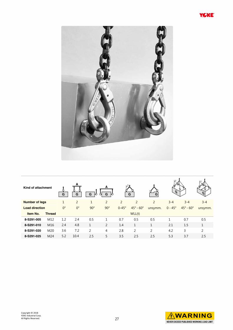
Kind of attachment
Number of legs 1 2 1 2 2 2 2 3-4 3-4 3-4
Load direction 0° 0° 90° 90° 0-45° 45° - 60° unsymm. 0 - 45° 45° - 60° unsymm.
Item No. Thread WLL(t)
8-S291-005 M12 1.2 2.4 0.5 1 0.7 0.5 0.5 1 0.7 0.5
8-S291-010 M16 2.4 4.8 1 2 1.4 1 1 2.1 1.5 1
8-S291-020 M20 3.6 7.2 2 4 2.8 2 2 4.2 3 2
8-S291-025 M24 5.2 10.4 2.5 5 3.5 2.5 2.5 5.3 3.7 2.5
NEVER EXCEED PUBLISHED WORKING LOAD LIMIT
WARNINGCopyright © 2018 YOKE Industrial Corp.All Rights Reserved. 27
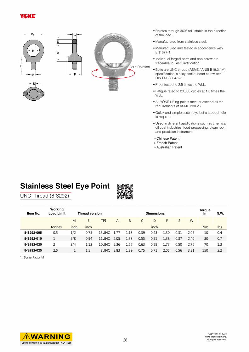
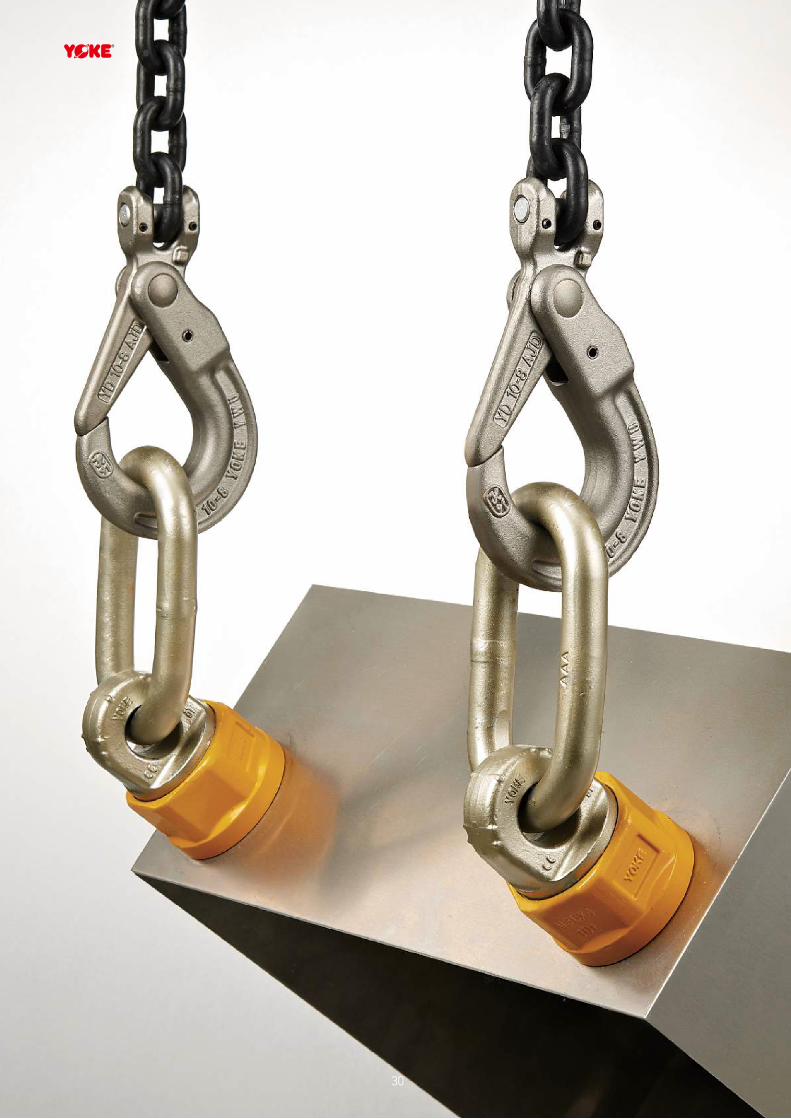
• Rotates through 360° adjustable in the direction of the load.
• Manufactured from stainless steel.
• Manufactured and tested in accordance with EN1677-1.
• Individual forged parts and cap screw are traceable to Test Certification.
• Bolts are UNC thread (ASME / ANSI B18.3.1M), specification is alloy socket head screw per DIN EN ISO 4762.
• Proof tested to 2.5 times the WLL.
• Fatigue rated to 20,000 cycles at 1.5 times the WLL.
• All YOKE Lifting points meet or exceed all the requirements of ASME B30.26.
• Quick and simple assembly, just a tapped hole is required.
• Used in different applications such as chemical oil coal industries, food processing, clean room and precision instrument.
Stainless Steel Eye PointUNC Thread (8-S292)
Item No.Working
Load Limit Thread version DimensionsTorque
in N.W.
M E TPI A B C D F S W
tonnes inch inch inch Nm lbs
8-S292-005 0.5 1/2 0.75 13UNC 1.77 1.18 0.39 0.43 1.30 0.31 2.05 10 0.4
8-S292-010 1 5/8 0.94 11UNC 2.05 1.38 0.55 0.51 1.38 0.37 2.40 30 0.7
8-S292-020 2 3/4 1.13 10UNC 2.36 1.57 0.63 0.59 1.73 0.50 2.76 70 1.3
8-S292-025 2.5 1 1.5 8UNC 2.83 1.89 0.75 0.71 2.05 0.56 3.31 150 2.2
CC
DD
AA
FF
EE
MM
BB
WW
SS
360° Rotation
» Chinese Patent » French Patent » Australian Patent
* Design Factor 4:1
NEVER EXCEED PUBLISHED WORKING LOAD LIMIT
WARNINGCopyright © 2018
YOKE Industrial Corp.All Rights Reserved.28
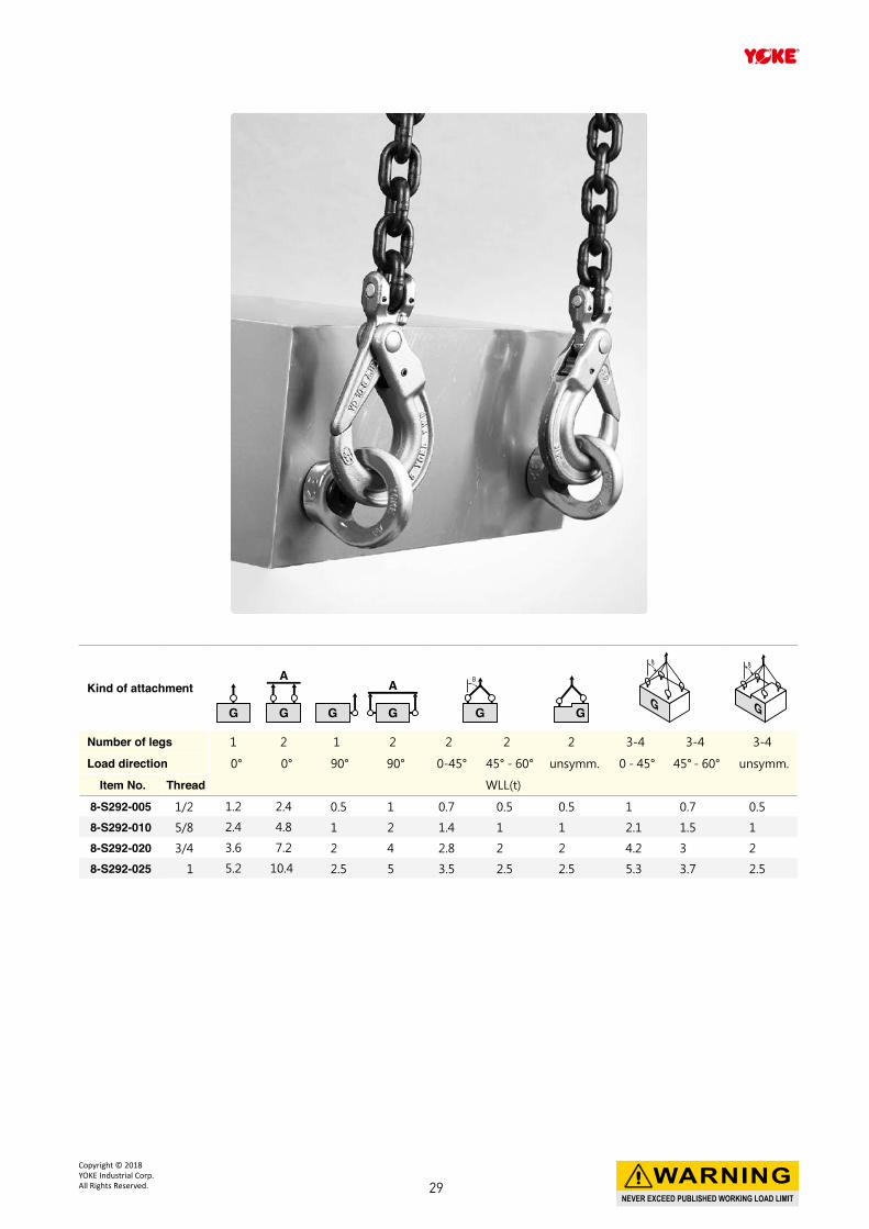
Kind of attachment
Number of legs 1 2 1 2 2 2 2 3-4 3-4 3-4
Load direction 0° 0° 90° 90° 0-45° 45° - 60° unsymm. 0 - 45° 45° - 60° unsymm.
Item No. Thread WLL(t)
8-S292-005 1/2 1.2 2.4 0.5 1 0.7 0.5 0.5 1 0.7 0.5
8-S292-010 5/8 2.4 4.8 1 2 1.4 1 1 2.1 1.5 1
8-S292-020 3/4 3.6 7.2 2 4 2.8 2 2 4.2 3 2
8-S292-025 1 5.2 10.4 2.5 5 3.5 2.5 2.5 5.3 3.7 2.5
NEVER EXCEED PUBLISHED WORKING LOAD LIMIT
WARNINGCopyright © 2018 YOKE Industrial Corp.All Rights Reserved. 29
30
* Design Factor 4:1
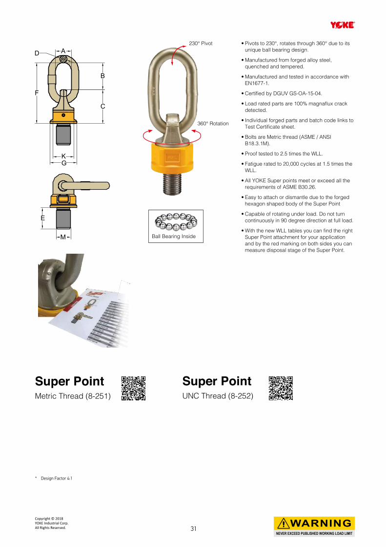
Super PointMetric Thread (8-251)
Super PointUNC Thread (8-252)
E
M
K
CC
BB
AADD
FF
G
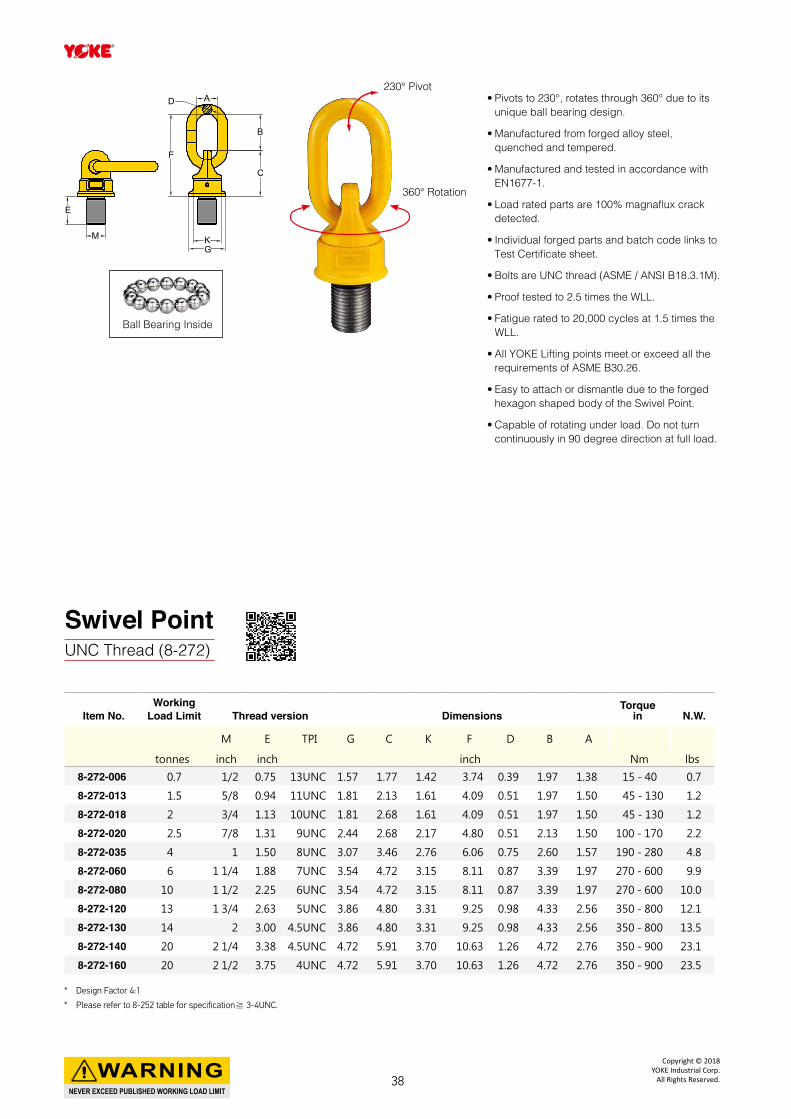
230° Pivot
360° Rotation
• Pivots to 230°, rotates through 360° due to its unique ball bearing design.
• Manufactured from forged alloy steel, quenched and tempered.
• Manufactured and tested in accordance with EN1677-1.
• Certified by DGUV GS-OA-15-04.
• Load rated parts are 100% magnaflux crack detected.
• Individual forged parts and batch code links to Test Certificate sheet.
• Bolts are Metric thread (ASME / ANSI B18.3.1M).
• Proof tested to 2.5 times the WLL.
• Fatigue rated to 20,000 cycles at 1.5 times the WLL.
• All YOKE Super points meet or exceed all the requirements of ASME B30.26.
• Easy to attach or dismantle due to the forged hexagon shaped body of the Super Point
• Capable of rotating under load. Do not turn continuously in 90 degree direction at full load.
• With the new WLL tables you can find the right Super Point attachment for your application and by the red marking on both sides you can measure disposal stage of the Super Point.
Ball Bearing Inside
NEVER EXCEED PUBLISHED WORKING LOAD LIMIT
WARNINGCopyright © 2018 YOKE Industrial Corp.All Rights Reserved. 31
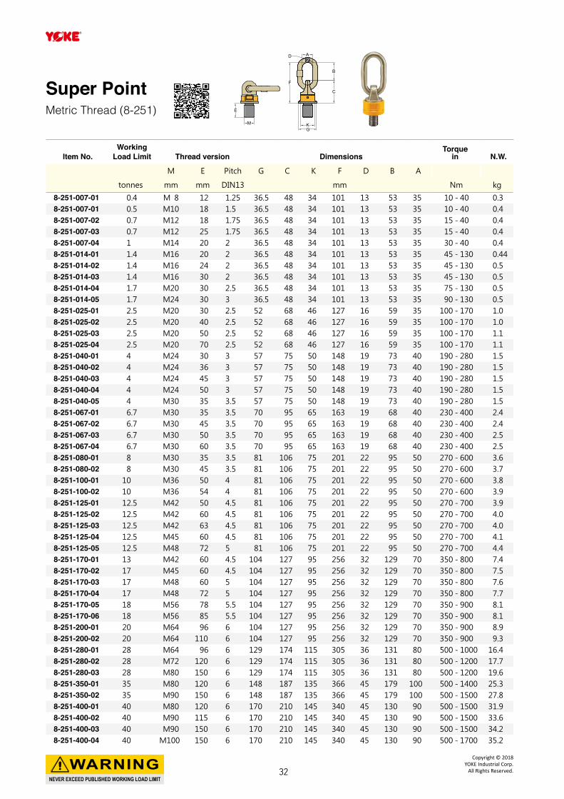
Super PointMetric Thread (8-251)
Item No.Working
Load Limit Thread version DimensionsTorque
in N.W.
M E Pitch G C K F D B A
tonnes mm mm DIN13 mm Nm kg
8-251-007-01 0.4 M 8 12 1.25 36.5 48 34 101 13 53 35 10 - 40 0.3 8-251-007-01 0.5 M10 18 1.5 36.5 48 34 101 13 53 35 10 - 40 0.4 8-251-007-02 0.7 M12 18 1.75 36.5 48 34 101 13 53 35 15 - 40 0.4 8-251-007-03 0.7 M12 25 1.75 36.5 48 34 101 13 53 35 15 - 40 0.4 8-251-007-04 1 M14 20 2 36.5 48 34 101 13 53 35 30 - 40 0.4 8-251-014-01 1.4 M16 20 2 36.5 48 34 101 13 53 35 45 - 130 0.448-251-014-02 1.4 M16 24 2 36.5 48 34 101 13 53 35 45 - 130 0.5 8-251-014-03 1.4 M16 30 2 36.5 48 34 101 13 53 35 45 - 130 0.5 8-251-014-04 1.7 M20 30 2.5 36.5 48 34 101 13 53 35 75 - 130 0.5 8-251-014-05 1.7 M24 30 3 36.5 48 34 101 13 53 35 90 - 130 0.5 8-251-025-01 2.5 M20 30 2.5 52 68 46 127 16 59 35 100 - 170 1.0 8-251-025-02 2.5 M20 40 2.5 52 68 46 127 16 59 35 100 - 170 1.0 8-251-025-03 2.5 M20 50 2.5 52 68 46 127 16 59 35 100 - 170 1.1 8-251-025-04 2.5 M20 70 2.5 52 68 46 127 16 59 35 100 - 170 1.1 8-251-040-01 4 M24 30 3 57 75 50 148 19 73 40 190 - 280 1.5 8-251-040-02 4 M24 36 3 57 75 50 148 19 73 40 190 - 280 1.5 8-251-040-03 4 M24 45 3 57 75 50 148 19 73 40 190 - 280 1.5 8-251-040-04 4 M24 50 3 57 75 50 148 19 73 40 190 - 280 1.5 8-251-040-05 4 M30 35 3.5 57 75 50 148 19 73 40 190 - 280 1.5 8-251-067-01 6.7 M30 35 3.5 70 95 65 163 19 68 40 230 - 400 2.4 8-251-067-02 6.7 M30 45 3.5 70 95 65 163 19 68 40 230 - 400 2.4 8-251-067-03 6.7 M30 50 3.5 70 95 65 163 19 68 40 230 - 400 2.5 8-251-067-04 6.7 M30 60 3.5 70 95 65 163 19 68 40 230 - 400 2.5 8-251-080-01 8 M30 35 3.5 81 106 75 201 22 95 50 270 - 600 3.6 8-251-080-02 8 M30 45 3.5 81 106 75 201 22 95 50 270 - 600 3.7 8-251-100-01 10 M36 50 4 81 106 75 201 22 95 50 270 - 600 3.8 8-251-100-02 10 M36 54 4 81 106 75 201 22 95 50 270 - 600 3.9 8-251-125-01 12.5 M42 50 4.5 81 106 75 201 22 95 50 270 - 700 3.9 8-251-125-02 12.5 M42 60 4.5 81 106 75 201 22 95 50 270 - 700 4.0 8-251-125-03 12.5 M42 63 4.5 81 106 75 201 22 95 50 270 - 700 4.0 8-251-125-04 12.5 M45 60 4.5 81 106 75 201 22 95 50 270 - 700 4.1 8-251-125-05 12.5 M48 72 5 81 106 75 201 22 95 50 270 - 700 4.4 8-251-170-01 13 M42 60 4.5 104 127 95 256 32 129 70 350 - 800 7.4 8-251-170-02 17 M45 60 4.5 104 127 95 256 32 129 70 350 - 800 7.5 8-251-170-03 17 M48 60 5 104 127 95 256 32 129 70 350 - 800 7.6 8-251-170-04 17 M48 72 5 104 127 95 256 32 129 70 350 - 800 7.7 8-251-170-05 18 M56 78 5.5 104 127 95 256 32 129 70 350 - 900 8.1 8-251-170-06 18 M56 85 5.5 104 127 95 256 32 129 70 350 - 900 8.1 8-251-200-01 20 M64 96 6 104 127 95 256 32 129 70 350 - 900 8.9 8-251-200-02 20 M64 110 6 104 127 95 256 32 129 70 350 - 900 9.3 8-251-280-01 28 M64 96 6 129 174 115 305 36 131 80 500 - 1000 16.4 8-251-280-02 28 M72 120 6 129 174 115 305 36 131 80 500 - 1200 17.7 8-251-280-03 28 M80 150 6 129 174 115 305 36 131 80 500 - 1200 19.6 8-251-350-01 35 M80 120 6 148 187 135 366 45 179 100 500 - 1400 25.3 8-251-350-02 35 M90 150 6 148 187 135 366 45 179 100 500 - 1500 27.8 8-251-400-01 40 M80 120 6 170 210 145 340 45 130 90 500 - 1500 31.98-251-400-02 40 M90 115 6 170 210 145 340 45 130 90 500 - 1500 33.68-251-400-03 40 M90 150 6 170 210 145 340 45 130 90 500 - 1500 34.28-251-400-04 40 M100 150 6 170 210 145 340 45 130 90 500 - 1700 35.2
E
M K
CC
BB
AADD
FF
G
NEVER EXCEED PUBLISHED WORKING LOAD LIMIT
WARNINGCopyright © 2018
YOKE Industrial Corp.All Rights Reserved.32
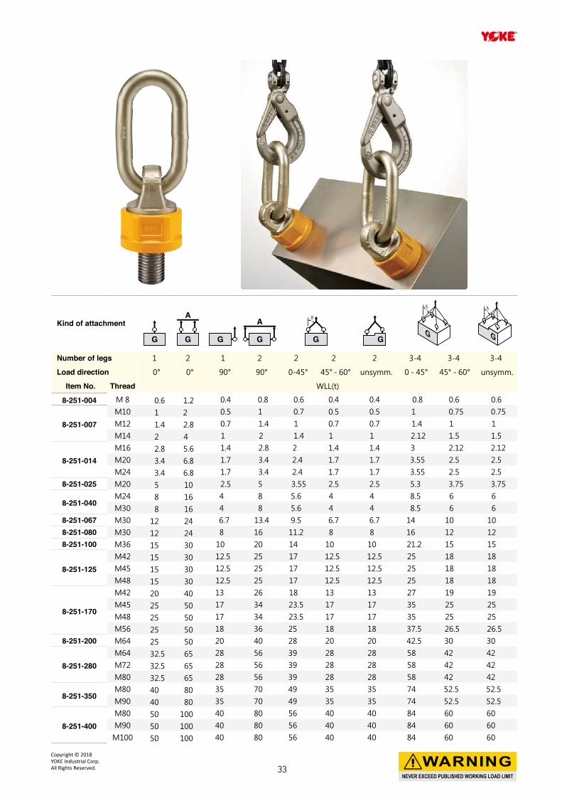
Kind of attachment
Number of legs 1 2 1 2 2 2 2 3-4 3-4 3-4
Load direction 0° 0° 90° 90° 0-45° 45° - 60° unsymm. 0 - 45° 45° - 60° unsymm.
Item No. Thread WLL(t)
8-251-004 M 8 0.6 1.2 0.4 0.8 0.6 0.4 0.4 0.8 0.6 0.6
8-251-007M10 1 2 0.5 1 0.7 0.5 0.5 1 0.75 0.75
M12 1.4 2.8 0.7 1.4 1 0.7 0.7 1.4 1 1
M14 2 4 1 2 1.4 1 1 2.12 1.5 1.5
8-251-014M16 2.8 5.6 1.4 2.8 2 1.4 1.4 3 2.12 2.12
M20 3.4 6.8 1.7 3.4 2.4 1.7 1.7 3.55 2.5 2.5
M24 3.4 6.8 1.7 3.4 2.4 1.7 1.7 3.55 2.5 2.58-251-025 M20 5 10 2.5 5 3.55 2.5 2.5 5.3 3.75 3.75
8-251-040M24 8 16 4 8 5.6 4 4 8.5 6 6
M30 8 16 4 8 5.6 4 4 8.5 6 68-251-067 M30 12 24 6.7 13.4 9.5 6.7 6.7 14 10 108-251-080 M30 12 24 8 16 11.2 8 8 16 12 128-251-100 M36 15 30 10 20 14 10 10 21.2 15 15
8-251-125M42 15 30 12.5 25 17 12.5 12.5 25 18 18
M45 15 30 12.5 25 17 12.5 12.5 25 18 18
M48 15 30 12.5 25 17 12.5 12.5 25 18 18
8-251-170
M42 20 40 13 26 18 13 13 27 19 19
M45 25 50 17 34 23.5 17 17 35 25 25
M48 25 50 17 34 23.5 17 17 35 25 25
M56 25 50 18 36 25 18 18 37.5 26.5 26.58-251-200 M64 25 50 20 40 28 20 20 42.5 30 30
8-251-280M64 32.5 65 28 56 39 28 28 58 42 42
M72 32.5 65 28 56 39 28 28 58 42 42
M80 32.5 65 28 56 39 28 28 58 42 42
8-251-350M80 40 80 35 70 49 35 35 74 52.5 52.5
M90 40 80 35 70 49 35 35 74 52.5 52.5
8-251-400M80 50 100 40 80 56 40 40 84 60 60
M90 50 100 40 80 56 40 40 84 60 60
M100 50 100 40 80 56 40 40 84 60 60
NEVER EXCEED PUBLISHED WORKING LOAD LIMIT
WARNINGCopyright © 2018 YOKE Industrial Corp.All Rights Reserved. 33
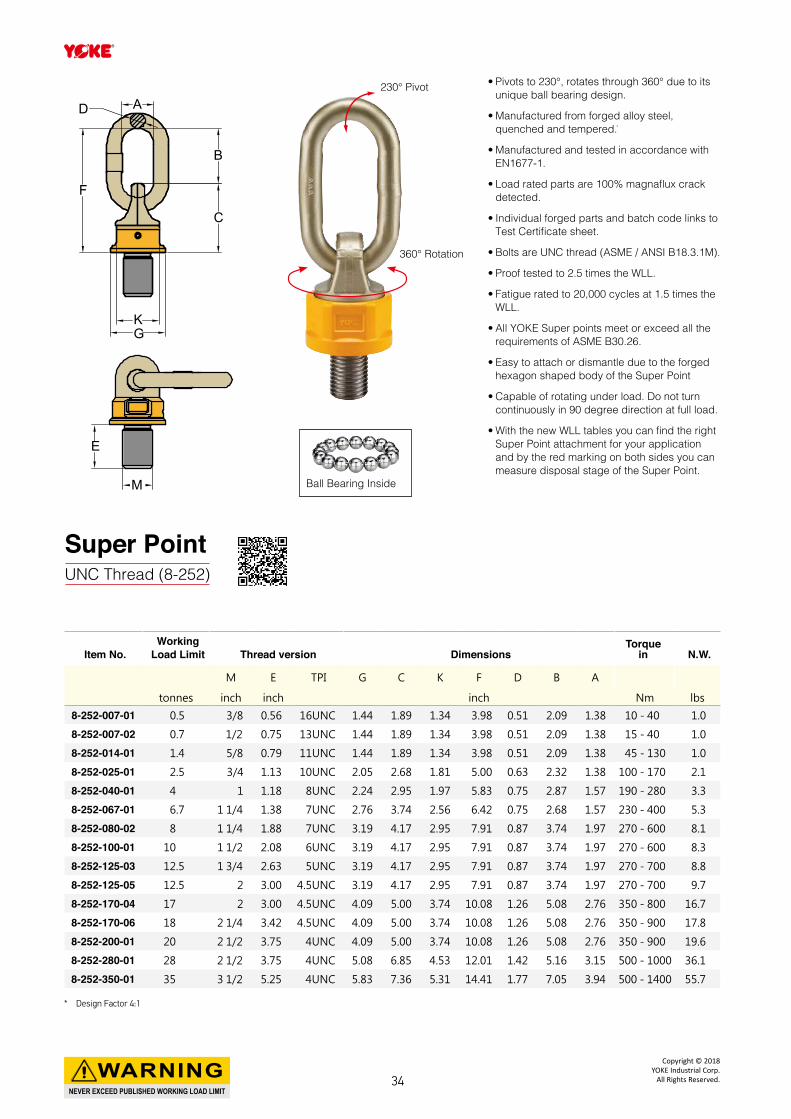
Super PointUNC Thread (8-252)
Item No.Working
Load Limit Thread version DimensionsTorque
in N.W.
M E TPI G C K F D B A
tonnes inch inch inch Nm lbs
8-252-007-01 0.5 3/8 0.56 16UNC 1.44 1.89 1.34 3.98 0.51 2.09 1.38 10 - 40 1.0
8-252-007-02 0.7 1/2 0.75 13UNC 1.44 1.89 1.34 3.98 0.51 2.09 1.38 15 - 40 1.0
8-252-014-01 1.4 5/8 0.79 11UNC 1.44 1.89 1.34 3.98 0.51 2.09 1.38 45 - 130 1.0
8-252-025-01 2.5 3/4 1.13 10UNC 2.05 2.68 1.81 5.00 0.63 2.32 1.38 100 - 170 2.1
8-252-040-01 4 1 1.18 8UNC 2.24 2.95 1.97 5.83 0.75 2.87 1.57 190 - 280 3.3
8-252-067-01 6.7 1 1/4 1.38 7UNC 2.76 3.74 2.56 6.42 0.75 2.68 1.57 230 - 400 5.3
8-252-080-02 8 1 1/4 1.88 7UNC 3.19 4.17 2.95 7.91 0.87 3.74 1.97 270 - 600 8.1
8-252-100-01 10 1 1/2 2.08 6UNC 3.19 4.17 2.95 7.91 0.87 3.74 1.97 270 - 600 8.3
8-252-125-03 12.5 1 3/4 2.63 5UNC 3.19 4.17 2.95 7.91 0.87 3.74 1.97 270 - 700 8.8
8-252-125-05 12.5 2 3.00 4.5UNC 3.19 4.17 2.95 7.91 0.87 3.74 1.97 270 - 700 9.7
8-252-170-04 17 2 3.00 4.5UNC 4.09 5.00 3.74 10.08 1.26 5.08 2.76 350 - 800 16.7
8-252-170-06 18 2 1/4 3.42 4.5UNC 4.09 5.00 3.74 10.08 1.26 5.08 2.76 350 - 900 17.8
8-252-200-01 20 2 1/2 3.75 4UNC 4.09 5.00 3.74 10.08 1.26 5.08 2.76 350 - 900 19.6
8-252-280-01 28 2 1/2 3.75 4UNC 5.08 6.85 4.53 12.01 1.42 5.16 3.15 500 - 1000 36.1
8-252-350-01 35 3 1/2 5.25 4UNC 5.83 7.36 5.31 14.41 1.77 7.05 3.94 500 - 1400 55.7
• Pivots to 230°, rotates through 360° due to its unique ball bearing design.
• Manufactured from forged alloy steel, quenched and tempered. ̇
• Manufactured and tested in accordance with EN1677-1.
• Load rated parts are 100% magnaflux crack detected.
• Individual forged parts and batch code links to Test Certificate sheet.
• Bolts are UNC thread (ASME / ANSI B18.3.1M).
• Proof tested to 2.5 times the WLL.
• Fatigue rated to 20,000 cycles at 1.5 times the WLL.
• All YOKE Super points meet or exceed all the requirements of ASME B30.26.
• Easy to attach or dismantle due to the forged hexagon shaped body of the Super Point
• Capable of rotating under load. Do not turn continuously in 90 degree direction at full load.
• With the new WLL tables you can find the right Super Point attachment for your application and by the red marking on both sides you can measure disposal stage of the Super Point.
E
M
K
CC
BB
AADD
FF
G
230° Pivot
360° Rotation
Ball Bearing Inside
* Design Factor 4:1
NEVER EXCEED PUBLISHED WORKING LOAD LIMIT
WARNINGCopyright © 2018
YOKE Industrial Corp.All Rights Reserved.34
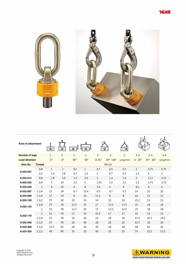
Kind of attachment
Number of legs 1 2 1 2 2 2 2 3-4 3-4 3-4
Load direction 0° 0° 90° 90° 0-45° 45° - 60° unsymm. 0 - 45° 45° - 60° unsymm.
Item No. Thread WLL(t)
8-252-0073/8 1 2 0.5 1 0.7 0.5 0.5 1 0.75 0.75
1/2 1.4 2.8 0.7 1.4 1 0.7 0.7 1.4 1 1
8-252-014 5/8 2.8 5.6 1.4 2.8 2 1.4 1.4 3 2.12 2.12
8-252-025 3/4 5 10 2.5 5 3.55 2.5 2.5 5.3 3.75 3.75
8-252-040 1 8 16 4 8 5.6 4 4 8.5 6 6
8-252-067 1 1/4 12 24 6.7 13.4 9.5 6.7 6.7 14 10 10
8-252-080 1 1/4 12 24 8 16 11.2 8 8 16 12 12
8-252-100 1 1/2 15 30 10 20 14 10 10 21.2 15 15
8-252-125 1 3/4 15 30 12.5 25 17 12.5 12.5 25 18 18
2 15 30 12.5 25 17 12.5 12.5 25 18 18
8-252-1702 25 50 17 34 23.5 17 17 35 25 25
2 1/4 25 50 18 36 25 18 18 37.5 26.5 26.5
8-252-200 2 1/2 25 50 20 40 28 20 20 42.5 30 30
8-252-280 2 1/2 32.5 65 28 56 39 28 28 58 42 42
8-252-350 3 1/2 40 80 35 70 49 35 35 74 52.5 52.5
NEVER EXCEED PUBLISHED WORKING LOAD LIMIT
WARNINGCopyright © 2018 YOKE Industrial Corp.All Rights Reserved. 35
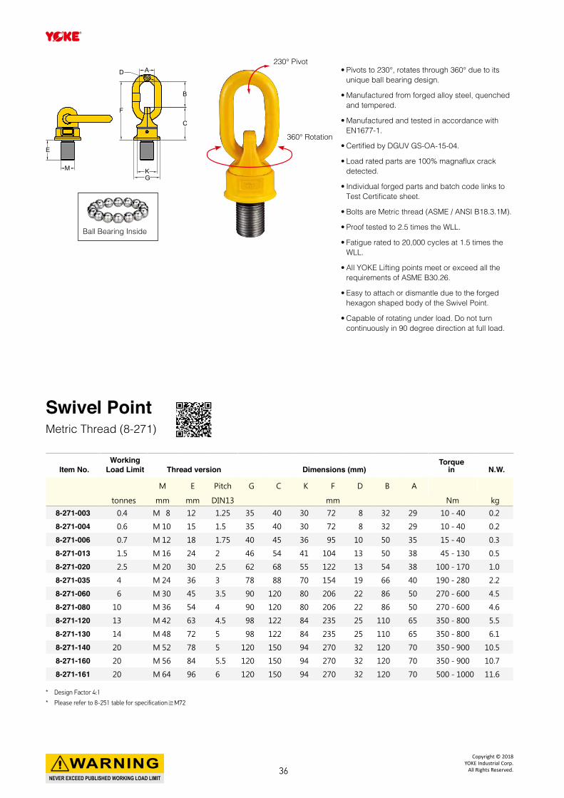
• Pivots to 230°, rotates through 360° due to its unique ball bearing design.
• Manufactured from forged alloy steel, quenched and tempered.
• Manufactured and tested in accordance with EN1677-1.
• Certified by DGUV GS-OA-15-04.
• Load rated parts are 100% magnaflux crack detected.
• Individual forged parts and batch code links to Test Certificate sheet.
• Bolts are Metric thread (ASME / ANSI B18.3.1M).
• Proof tested to 2.5 times the WLL.
• Fatigue rated to 20,000 cycles at 1.5 times the WLL.
• All YOKE Lifting points meet or exceed all the requirements of ASME B30.26.
• Easy to attach or dismantle due to the forged hexagon shaped body of the Swivel Point.
• Capable of rotating under load. Do not turn continuously in 90 degree direction at full load.
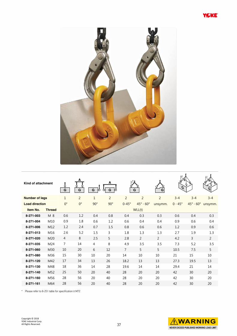
Swivel PointMetric Thread (8-271)
Item No.Working
Load Limit Thread version Dimensions (mm)Torque
in N.W.
M E Pitch G C K F D B A
tonnes mm mm DIN13 mm Nm kg
8-271-003 0.4 M 8 12 1.25 35 40 30 72 8 32 29 10 - 40 0.2
8-271-004 0.6 M 10 15 1.5 35 40 30 72 8 32 29 10 - 40 0.2
8-271-006 0.7 M 12 18 1.75 40 45 36 95 10 50 35 15 - 40 0.3
8-271-013 1.5 M 16 24 2 46 54 41 104 13 50 38 45 - 130 0.5
8-271-020 2.5 M 20 30 2.5 62 68 55 122 13 54 38 100 - 170 1.0
8-271-035 4 M 24 36 3 78 88 70 154 19 66 40 190 - 280 2.2
8-271-060 6 M 30 45 3.5 90 120 80 206 22 86 50 270 - 600 4.5
8-271-080 10 M 36 54 4 90 120 80 206 22 86 50 270 - 600 4.6
8-271-120 13 M 42 63 4.5 98 122 84 235 25 110 65 350 - 800 5.5
8-271-130 14 M 48 72 5 98 122 84 235 25 110 65 350 - 800 6.1
8-271-140 20 M 52 78 5 120 150 94 270 32 120 70 350 - 900 10.5
8-271-160 20 M 56 84 5.5 120 150 94 270 32 120 70 350 - 900 10.7
8-271-161 20 M 64 96 6 120 150 94 270 32 120 70 500 - 1000 11.6
* Design Factor 4:1
* Please refer to 8-251 table for specification≧M72
E
M K
CC
BB
AADD
FF
G
Ball Bearing Inside
230° Pivot
360° Rotation
NEVER EXCEED PUBLISHED WORKING LOAD LIMIT
WARNINGCopyright © 2018
YOKE Industrial Corp.All Rights Reserved.36
* Please refer to 8-251 table for specification≧M72
Kind of attachment
Number of legs 1 2 1 2 2 2 2 3-4 3-4 3-4
Load direction 0° 0° 90° 90° 0-45° 45° - 60° unsymm. 0 - 45° 45° - 60° unsymm.
Item No. Thread WLL(t)
8-271-003 M 8 0.6 1.2 0.4 0.8 0.4 0.3 0.3 0.6 0.4 0.3
8-271-004 M10 0.9 1.8 0.6 1.2 0.6 0.4 0.4 0.9 0.6 0.4
8-271-006 M12 1.2 2.4 0.7 1.5 0.8 0.6 0.6 1.2 0.9 0.6
8-271-013 M16 2.6 5.2 1.5 3 1.8 1.3 1.3 2.7 1.9 1.3
8-271-020 M20 4 8 2.5 5 2.8 2 2 4.2 3 2
8-271-035 M24 7 14 4 8 4.9 3.5 3.5 7.3 5.2 3.5
8-271-060 M30 10 20 6 12 7 5 5 10.5 7.5 5
8-271-080 M36 15 30 10 20 14 10 10 21 15 10
8-271-120 M42 17 34 13 26 18.2 13 13 27.3 19.5 13
8-271-130 M48 18 36 14 28 19.6 14 14 29.4 21 14
8-271-140 M52 25 50 20 40 28 20 20 42 30 20
8-271-160 M56 28 56 20 40 28 20 20 42 30 20
8-271-161 M64 28 56 20 40 28 20 20 42 30 20
NEVER EXCEED PUBLISHED WORKING LOAD LIMIT
WARNINGCopyright © 2018 YOKE Industrial Corp.All Rights Reserved. 37
• Pivots to 230°, rotates through 360° due to its unique ball bearing design.
• Manufactured from forged alloy steel, quenched and tempered.
• Manufactured and tested in accordance with EN1677-1.
• Load rated parts are 100% magnaflux crack detected.
• Individual forged parts and batch code links to Test Certificate sheet.
• Bolts are UNC thread (ASME / ANSI B18.3.1M).
• Proof tested to 2.5 times the WLL.
• Fatigue rated to 20,000 cycles at 1.5 times the WLL.
• All YOKE Lifting points meet or exceed all the requirements of ASME B30.26.
• Easy to attach or dismantle due to the forged hexagon shaped body of the Swivel Point.
• Capable of rotating under load. Do not turn continuously in 90 degree direction at full load.
Swivel PointUNC Thread (8-272)
Item No.Working
Load Limit Thread version DimensionsTorque
in N.W.
M E TPI G C K F D B A
tonnes inch inch inch Nm lbs
8-272-006 0.7 1/2 0.75 13UNC 1.57 1.77 1.42 3.74 0.39 1.97 1.38 15 - 40 0.7
8-272-013 1.5 5/8 0.94 11UNC 1.81 2.13 1.61 4.09 0.51 1.97 1.50 45 - 130 1.2
8-272-018 2 3/4 1.13 10UNC 1.81 2.68 1.61 4.09 0.51 1.97 1.50 45 - 130 1.2
8-272-020 2.5 7/8 1.31 9UNC 2.44 2.68 2.17 4.80 0.51 2.13 1.50 100 - 170 2.2
8-272-035 4 1 1.50 8UNC 3.07 3.46 2.76 6.06 0.75 2.60 1.57 190 - 280 4.8
8-272-060 6 1 1/4 1.88 7UNC 3.54 4.72 3.15 8.11 0.87 3.39 1.97 270 - 600 9.9
8-272-080 10 1 1/2 2.25 6UNC 3.54 4.72 3.15 8.11 0.87 3.39 1.97 270 - 600 10.0
8-272-120 13 1 3/4 2.63 5UNC 3.86 4.80 3.31 9.25 0.98 4.33 2.56 350 - 800 12.1
8-272-130 14 2 3.00 4.5UNC 3.86 4.80 3.31 9.25 0.98 4.33 2.56 350 - 800 13.5
8-272-140 20 2 1/4 3.38 4.5UNC 4.72 5.91 3.70 10.63 1.26 4.72 2.76 350 - 900 23.1
8-272-160 20 2 1/2 3.75 4UNC 4.72 5.91 3.70 10.63 1.26 4.72 2.76 350 - 900 23.5
* Design Factor 4:1
* Please refer to 8-252 table for specification≧ 3-4UNC.
E
M K
CC
BB
AADD
FF
G
Ball Bearing Inside
230° Pivot
360° Rotation
NEVER EXCEED PUBLISHED WORKING LOAD LIMIT
WARNINGCopyright © 2018
YOKE Industrial Corp.All Rights Reserved.38
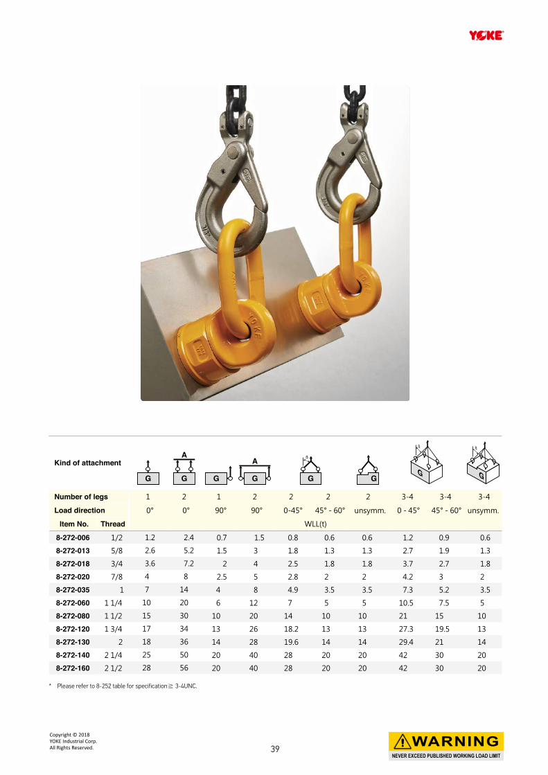
* Please refer to 8-252 table for specification≧ 3-4UNC.
Kind of attachment
Number of legs 1 2 1 2 2 2 2 3-4 3-4 3-4
Load direction 0° 0° 90° 90° 0-45° 45° - 60° unsymm. 0 - 45° 45° - 60° unsymm.
Item No. Thread WLL(t)
8-272-006 1/2 1.2 2.4 0.7 1.5 0.8 0.6 0.6 1.2 0.9 0.6
8-272-013 5/8 2.6 5.2 1.5 3 1.8 1.3 1.3 2.7 1.9 1.3
8-272-018 3/4 3.6 7.2 2 4 2.5 1.8 1.8 3.7 2.7 1.8
8-272-020 7/8 4 8 2.5 5 2.8 2 2 4.2 3 2
8-272-035 1 7 14 4 8 4.9 3.5 3.5 7.3 5.2 3.5
8-272-060 1 1/4 10 20 6 12 7 5 5 10.5 7.5 5
8-272-080 1 1/2 15 30 10 20 14 10 10 21 15 10
8-272-120 1 3/4 17 34 13 26 18.2 13 13 27.3 19.5 13
8-272-130 2 18 36 14 28 19.6 14 14 29.4 21 14
8-272-140 2 1/4 25 50 20 40 28 20 20 42 30 20
8-272-160 2 1/2 28 56 20 40 28 20 20 42 30 20
NEVER EXCEED PUBLISHED WORKING LOAD LIMIT
WARNINGCopyright © 2018 YOKE Industrial Corp.All Rights Reserved. 39
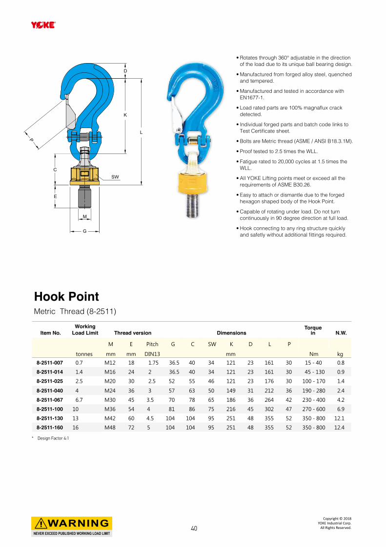
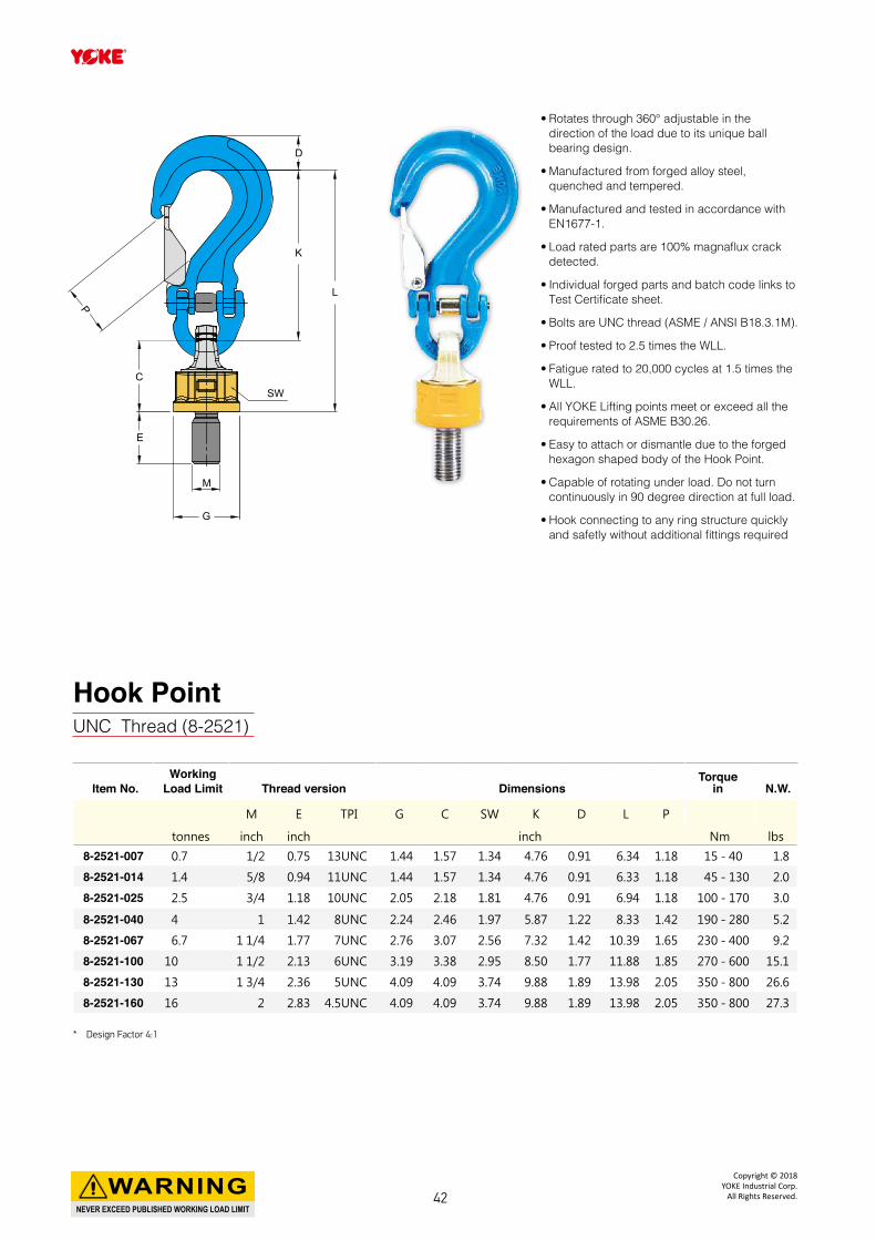
• Rotates through 360° adjustable in the direction of the load due to its unique ball bearing design.
• Manufactured from forged alloy steel, quenched and tempered.
• Manufactured and tested in accordance with EN1677-1.
• Load rated parts are 100% magnaflux crack detected.
• Individual forged parts and batch code links to Test Certificate sheet.
• Bolts are Metric thread (ASME / ANSI B18.3.1M).
• Proof tested to 2.5 times the WLL.
• Fatigue rated to 20,000 cycles at 1.5 times the WLL.
• All YOKE Lifting points meet or exceed all the requirements of ASME B30.26.
• Easy to attach or dismantle due to the forged hexagon shaped body of the Hook Point.
• Capable of rotating under load. Do not turn continuously in 90 degree direction at full load.
• Hook connecting to any ring structure quickly and safetly without additional fittings required.
C
P
E
SW
G
M
L
K
D
Hook PointMetric Thread (8-2511)
Item No.Working
Load Limit Thread version DimensionsTorque
in N.W.
M E Pitch G C SW K D L P
tonnes mm mm DIN13 mm Nm kg
8-2511-007 0.7 M12 18 1.75 36.5 40 34 121 23 161 30 15 - 40 0.8
8-2511-014 1.4 M16 24 2 36.5 40 34 121 23 161 30 45 - 130 0.9
8-2511-025 2.5 M20 30 2.5 52 55 46 121 23 176 30 100 - 170 1.4
8-2511-040 4 M24 36 3 57 63 50 149 31 212 36 190 - 280 2.4
8-2511-067 6.7 M30 45 3.5 70 78 65 186 36 264 42 230 - 400 4.2
8-2511-100 10 M36 54 4 81 86 75 216 45 302 47 270 - 600 6.9
8-2511-130 13 M42 60 4.5 104 104 95 251 48 355 52 350 - 800 12.1
8-2511-160 16 M48 72 5 104 104 95 251 48 355 52 350 - 800 12.4
* Design Factor 4:1
NEVER EXCEED PUBLISHED WORKING LOAD LIMIT
WARNINGCopyright © 2018
YOKE Industrial Corp.All Rights Reserved.40
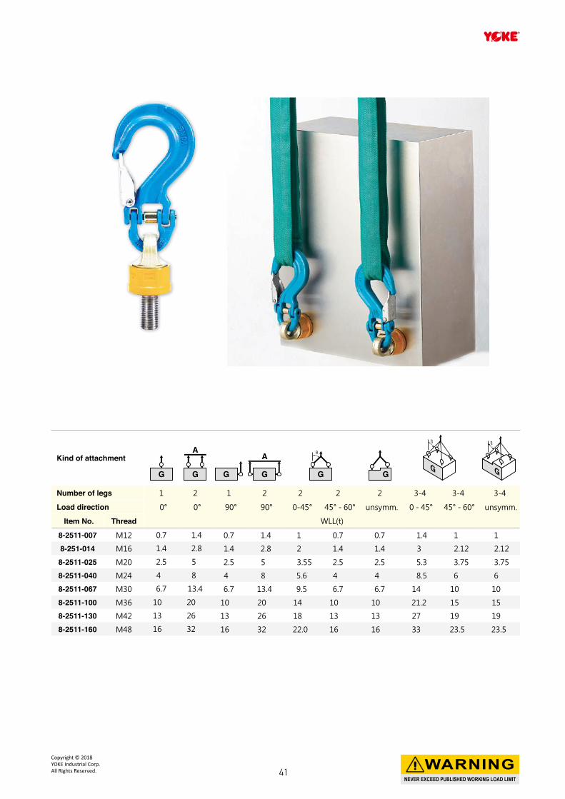
Kind of attachment
Number of legs 1 2 1 2 2 2 2 3-4 3-4 3-4
Load direction 0° 0° 90° 90° 0-45° 45° - 60° unsymm. 0 - 45° 45° - 60° unsymm.
Item No. Thread WLL(t)
8-2511-007 M12 0.7 1.4 0.7 1.4 1 0.7 0.7 1.4 1 1
8-251-014 M16 1.4 2.8 1.4 2.8 2 1.4 1.4 3 2.12 2.12
8-2511-025 M20 2.5 5 2.5 5 3.55 2.5 2.5 5.3 3.75 3.75
8-2511-040 M24 4 8 4 8 5.6 4 4 8.5 6 6
8-2511-067 M30 6.7 13.4 6.7 13.4 9.5 6.7 6.7 14 10 10
8-2511-100 M36 10 20 10 20 14 10 10 21.2 15 15
8-2511-130 M42 13 26 13 26 18 13 13 27 19 19
8-2511-160 M48 16 32 16 32 22.0 16 16 33 23.5 23.5
NEVER EXCEED PUBLISHED WORKING LOAD LIMIT
WARNINGCopyright © 2018 YOKE Industrial Corp.All Rights Reserved. 41
• Rotates through 360° adjustable in the direction of the load due to its unique ball bearing design.
• Manufactured from forged alloy steel, quenched and tempered.
• Manufactured and tested in accordance with EN1677-1.
• Load rated parts are 100% magnaflux crack detected.
• Individual forged parts and batch code links to Test Certificate sheet.
• Bolts are UNC thread (ASME / ANSI B18.3.1M).
• Proof tested to 2.5 times the WLL.
• Fatigue rated to 20,000 cycles at 1.5 times the WLL.
• All YOKE Lifting points meet or exceed all the requirements of ASME B30.26.
• Easy to attach or dismantle due to the forged hexagon shaped body of the Hook Point.
• Capable of rotating under load. Do not turn continuously in 90 degree direction at full load.
• Hook connecting to any ring structure quickly and safetly without additional fittings required
C
P
E
SW
G
M
L
K
D
Hook PointUNC Thread (8-2521)
Item No.Working
Load Limit Thread version DimensionsTorque
in N.W.
M E TPI G C SW K D L P
tonnes inch inch inch Nm lbs
8-2521-007 0.7 1/2 0.75 13UNC 1.44 1.57 1.34 4.76 0.91 6.34 1.18 15 - 40 1.8
8-2521-014 1.4 5/8 0.94 11UNC 1.44 1.57 1.34 4.76 0.91 6.33 1.18 45 - 130 2.0
8-2521-025 2.5 3/4 1.18 10UNC 2.05 2.18 1.81 4.76 0.91 6.94 1.18 100 - 170 3.0
8-2521-040 4 1 1.42 8UNC 2.24 2.46 1.97 5.87 1.22 8.33 1.42 190 - 280 5.2
8-2521-067 6.7 1 1/4 1.77 7UNC 2.76 3.07 2.56 7.32 1.42 10.39 1.65 230 - 400 9.2
8-2521-100 10 1 1/2 2.13 6UNC 3.19 3.38 2.95 8.50 1.77 11.88 1.85 270 - 600 15.1
8-2521-130 13 1 3/4 2.36 5UNC 4.09 4.09 3.74 9.88 1.89 13.98 2.05 350 - 800 26.6
8-2521-160 16 2 2.83 4.5UNC 4.09 4.09 3.74 9.88 1.89 13.98 2.05 350 - 800 27.3
* Design Factor 4:1
NEVER EXCEED PUBLISHED WORKING LOAD LIMIT
WARNINGCopyright © 2018
YOKE Industrial Corp.All Rights Reserved.42
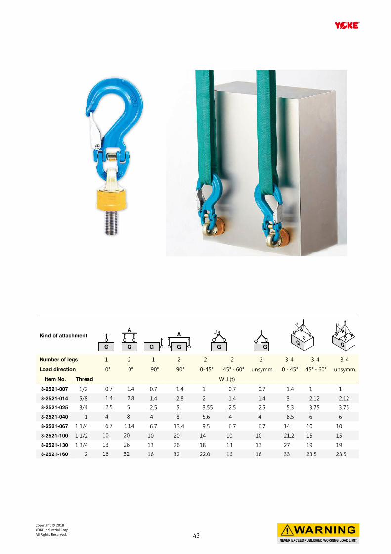
Kind of attachment
Number of legs 1 2 1 2 2 2 2 3-4 3-4 3-4
Load direction 0° 0° 90° 90° 0-45° 45° - 60° unsymm. 0 - 45° 45° - 60° unsymm.
Item No. Thread WLL(t)
8-2521-007 1/2 0.7 1.4 0.7 1.4 1 0.7 0.7 1.4 1 1
8-2521-014 5/8 1.4 2.8 1.4 2.8 2 1.4 1.4 3 2.12 2.12
8-2521-025 3/4 2.5 5 2.5 5 3.55 2.5 2.5 5.3 3.75 3.75
8-2521-040 1 4 8 4 8 5.6 4 4 8.5 6 6
8-2521-067 1 1/4 6.7 13.4 6.7 13.4 9.5 6.7 6.7 14 10 10
8-2521-100 1 1/2 10 20 10 20 14 10 10 21.2 15 15
8-2521-130 1 3/4 13 26 13 26 18 13 13 27 19 19
8-2521-160 2 16 32 16 32 22.0 16 16 33 23.5 23.5
NEVER EXCEED PUBLISHED WORKING LOAD LIMIT
WARNINGCopyright © 2018 YOKE Industrial Corp.All Rights Reserved. 43
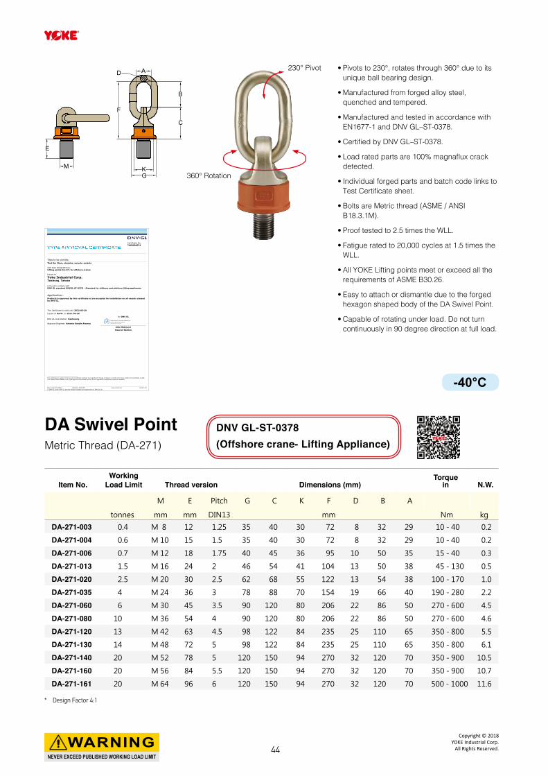
DA Swivel PointMetric Thread (DA-271)
Item No.Working
Load Limit Thread version Dimensions (mm)Torque
in N.W.
M E Pitch G C K F D B A
tonnes mm mm DIN13 mm Nm kg
DA-271-003 0.4 M 8 12 1.25 35 40 30 72 8 32 29 10 - 40 0.2
DA-271-004 0.6 M 10 15 1.5 35 40 30 72 8 32 29 10 - 40 0.2
DA-271-006 0.7 M 12 18 1.75 40 45 36 95 10 50 35 15 - 40 0.3
DA-271-013 1.5 M 16 24 2 46 54 41 104 13 50 38 45 - 130 0.5
DA-271-020 2.5 M 20 30 2.5 62 68 55 122 13 54 38 100 - 170 1.0
DA-271-035 4 M 24 36 3 78 88 70 154 19 66 40 190 - 280 2.2
DA-271-060 6 M 30 45 3.5 90 120 80 206 22 86 50 270 - 600 4.5
DA-271-080 10 M 36 54 4 90 120 80 206 22 86 50 270 - 600 4.6
DA-271-120 13 M 42 63 4.5 98 122 84 235 25 110 65 350 - 800 5.5
DA-271-130 14 M 48 72 5 98 122 84 235 25 110 65 350 - 800 6.1
DA-271-140 20 M 52 78 5 120 150 94 270 32 120 70 350 - 900 10.5
DA-271-160 20 M 56 84 5.5 120 150 94 270 32 120 70 350 - 900 10.7
DA-271-161 20 M 64 96 6 120 150 94 270 32 120 70 500 - 1000 11.6
• Pivots to 230°, rotates through 360° due to its unique ball bearing design.
• Manufactured from forged alloy steel, quenched and tempered.
• Manufactured and tested in accordance with EN1677-1 and DNV GL–ST-0378.
• Certified by DNV GL–ST-0378.
• Load rated parts are 100% magnaflux crack detected.
• Individual forged parts and batch code links to Test Certificate sheet.
• Bolts are Metric thread (ASME / ANSI B18.3.1M).
• Proof tested to 2.5 times the WLL.
• Fatigue rated to 20,000 cycles at 1.5 times the WLL.
• All YOKE Lifting points meet or exceed all the requirements of ASME B30.26.
• Easy to attach or dismantle due to the forged hexagon shaped body of the DA Swivel Point.
• Capable of rotating under load. Do not turn continuously in 90 degree direction at full load.
E
M K
CC
BB
AADD
FF
G
230° Pivot
360° Rotation
DNV GL-ST-0378 (Offshore crane- Lifting Appliance)
Form code: TA 1411a Revision: 2015-05 www.dnvgl.com Page 1 of 4 © DNV GL 2014. DNV GL and the Horizon Graphic are trademarks of DNV GL AS.
Certificate No: TAS00000T4
This is to certify: That the Chain, shackles, swivels, sockets with type designation(s) Lifting points DA-271 for offshore cranes Issued to
Yoke Industrial Corp. Taichung, Taiwan is found to comply with DNV GL standard DNVGL-ST-0378 – Standard for offshore and platform lifting appliances Application : Product(s) approved by this certificate is/are accepted for installation on all vessels classed by DNV GL.
This Certificate is valid until 2022-05-29. Issued at Høvik on 2017-05-30
DNV GL local station: Kaohsiung Approval Engineer: Antonio Sendin Alvarez
for DNV GL
Aldo Matteucci Head of Section
This Certificate is subject to terms and conditions overleaf. Any significant change in design or construction may render this Certificate invalid. The validity date relates to the Type Approval Certificate and not to the approval of equipment/systems installed.
Digitally Signed By: [email protected]
Signing Date: 31.05.2017
Location: DNV GL Høvik, Norway
-40°C
* Design Factor 4:1
NEVER EXCEED PUBLISHED WORKING LOAD LIMIT
WARNINGCopyright © 2018
YOKE Industrial Corp.All Rights Reserved.44
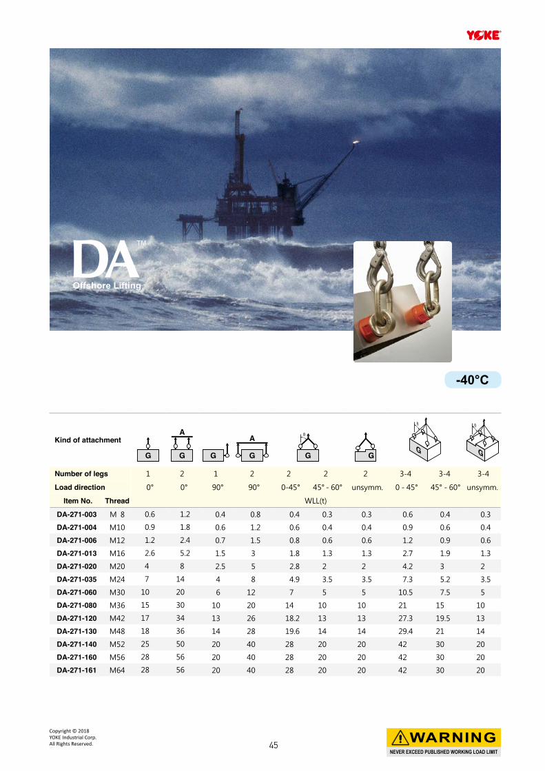
Kind of attachment
Number of legs 1 2 1 2 2 2 2 3-4 3-4 3-4
Load direction 0° 0° 90° 90° 0-45° 45° - 60° unsymm. 0 - 45° 45° - 60° unsymm.
Item No. Thread WLL(t)
DA-271-003 M 8 0.6 1.2 0.4 0.8 0.4 0.3 0.3 0.6 0.4 0.3
DA-271-004 M10 0.9 1.8 0.6 1.2 0.6 0.4 0.4 0.9 0.6 0.4
DA-271-006 M12 1.2 2.4 0.7 1.5 0.8 0.6 0.6 1.2 0.9 0.6
DA-271-013 M16 2.6 5.2 1.5 3 1.8 1.3 1.3 2.7 1.9 1.3
DA-271-020 M20 4 8 2.5 5 2.8 2 2 4.2 3 2
DA-271-035 M24 7 14 4 8 4.9 3.5 3.5 7.3 5.2 3.5
DA-271-060 M30 10 20 6 12 7 5 5 10.5 7.5 5
DA-271-080 M36 15 30 10 20 14 10 10 21 15 10
DA-271-120 M42 17 34 13 26 18.2 13 13 27.3 19.5 13
DA-271-130 M48 18 36 14 28 19.6 14 14 29.4 21 14
DA-271-140 M52 25 50 20 40 28 20 20 42 30 20
DA-271-160 M56 28 56 20 40 28 20 20 42 30 20
DA-271-161 M64 28 56 20 40 28 20 20 42 30 20
Offshore Lifting
-40°C
NEVER EXCEED PUBLISHED WORKING LOAD LIMIT
WARNINGCopyright © 2018 YOKE Industrial Corp.All Rights Reserved. 45
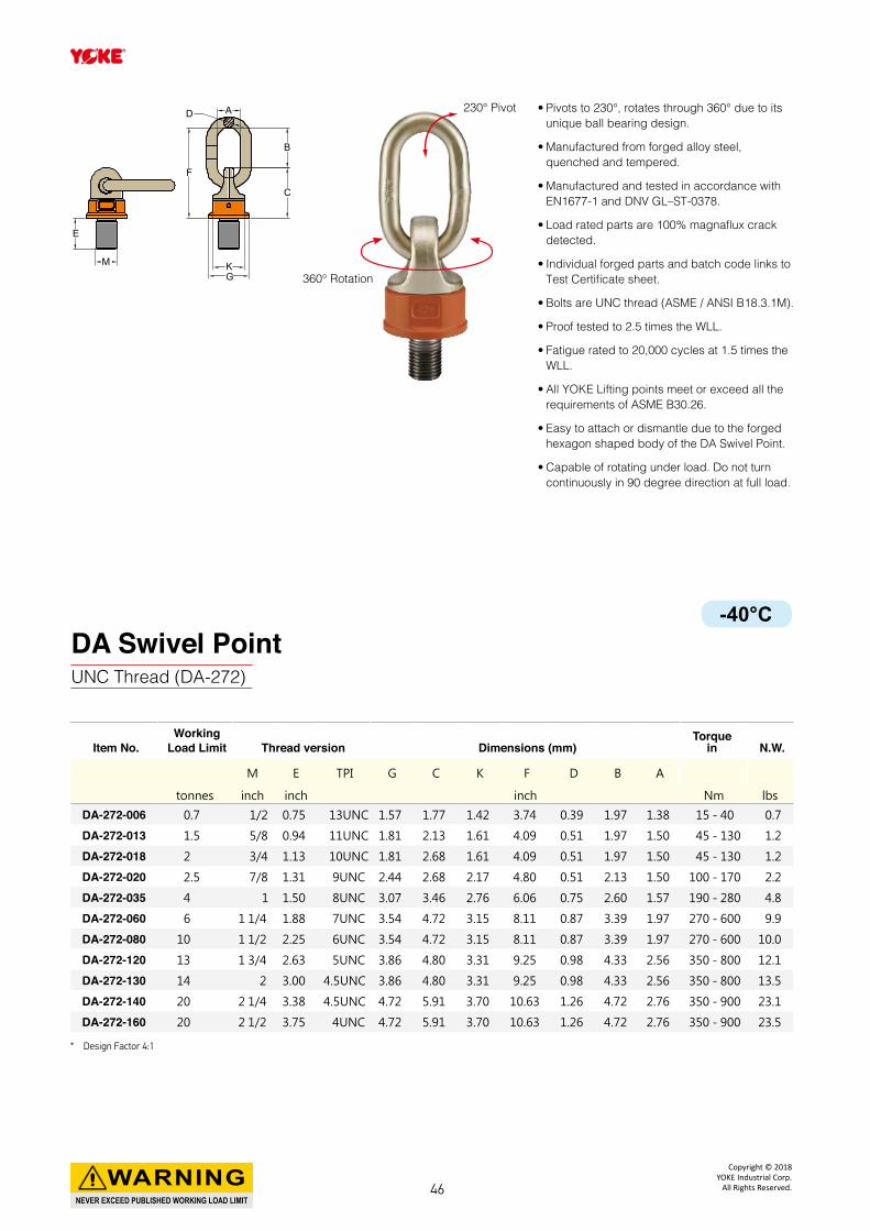
DA Swivel PointUNC Thread (DA-272)
E
M K
CC
BB
AADD
FF
G
230° Pivot
360° Rotation
Item No.Working
Load Limit Thread version Dimensions (mm)Torque
in N.W.
M E TPI G C K F D B A
tonnes inch inch inch Nm lbs
DA-272-006 0.7 1/2 0.75 13UNC 1.57 1.77 1.42 3.74 0.39 1.97 1.38 15 - 40 0.7
DA-272-013 1.5 5/8 0.94 11UNC 1.81 2.13 1.61 4.09 0.51 1.97 1.50 45 - 130 1.2
DA-272-018 2 3/4 1.13 10UNC 1.81 2.68 1.61 4.09 0.51 1.97 1.50 45 - 130 1.2
DA-272-020 2.5 7/8 1.31 9UNC 2.44 2.68 2.17 4.80 0.51 2.13 1.50 100 - 170 2.2
DA-272-035 4 1 1.50 8UNC 3.07 3.46 2.76 6.06 0.75 2.60 1.57 190 - 280 4.8
DA-272-060 6 1 1/4 1.88 7UNC 3.54 4.72 3.15 8.11 0.87 3.39 1.97 270 - 600 9.9
DA-272-080 10 1 1/2 2.25 6UNC 3.54 4.72 3.15 8.11 0.87 3.39 1.97 270 - 600 10.0
DA-272-120 13 1 3/4 2.63 5UNC 3.86 4.80 3.31 9.25 0.98 4.33 2.56 350 - 800 12.1
DA-272-130 14 2 3.00 4.5UNC 3.86 4.80 3.31 9.25 0.98 4.33 2.56 350 - 800 13.5
DA-272-140 20 2 1/4 3.38 4.5UNC 4.72 5.91 3.70 10.63 1.26 4.72 2.76 350 - 900 23.1
DA-272-160 20 2 1/2 3.75 4UNC 4.72 5.91 3.70 10.63 1.26 4.72 2.76 350 - 900 23.5
• Pivots to 230°, rotates through 360° due to its unique ball bearing design.
• Manufactured from forged alloy steel, quenched and tempered.
• Manufactured and tested in accordance with EN1677-1 and DNV GL–ST-0378.
• Load rated parts are 100% magnaflux crack detected.
• Individual forged parts and batch code links to Test Certificate sheet.
• Bolts are UNC thread (ASME / ANSI B18.3.1M).
• Proof tested to 2.5 times the WLL.
• Fatigue rated to 20,000 cycles at 1.5 times the WLL.
• All YOKE Lifting points meet or exceed all the requirements of ASME B30.26.
• Easy to attach or dismantle due to the forged hexagon shaped body of the DA Swivel Point.
• Capable of rotating under load. Do not turn continuously in 90 degree direction at full load.
-40°C
* Design Factor 4:1
NEVER EXCEED PUBLISHED WORKING LOAD LIMIT
WARNINGCopyright © 2018
YOKE Industrial Corp.All Rights Reserved.46
Kind of attachment
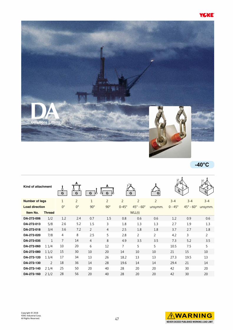
Number of legs 1 2 1 2 2 2 2 3-4 3-4 3-4
Load direction 0° 0° 90° 90° 0-45° 45° - 60° unsymm. 0 - 45° 45° - 60° unsymm.
Item No. Thread WLL(t)
DA-272-006 1/2 1.2 2.4 0.7 1.5 0.8 0.6 0.6 1.2 0.9 0.6
DA-272-013 5/8 2.6 5.2 1.5 3 1.8 1.3 1.3 2.7 1.9 1.3
DA-272-018 3/4 3.6 7.2 2 4 2.5 1.8 1.8 3.7 2.7 1.8
DA-272-020 7/8 4 8 2.5 5 2.8 2 2 4.2 3 2
DA-272-035 1 7 14 4 8 4.9 3.5 3.5 7.3 5.2 3.5
DA-272-060 1 1/4 10 20 6 12 7 5 5 10.5 7.5 5
DA-272-080 1 1/2 15 30 10 20 14 10 10 21 15 10
DA-272-120 1 3/4 17 34 13 26 18.2 13 13 27.3 19.5 13
DA-272-130 2 18 36 14 28 19.6 14 14 29.4 21 14
DA-272-140 2 1/4 25 50 20 40 28 20 20 42 30 20
DA-272-160 2 1/2 28 56 20 40 28 20 20 42 30 20
Offshore Lifting
-40°C
NEVER EXCEED PUBLISHED WORKING LOAD LIMIT
WARNINGCopyright © 2018 YOKE Industrial Corp.All Rights Reserved. 47
Item No.Working
Load Limit Thread Dimensions (mm)Torque
in N.W.
tonnes M A B D E F G
5 : 1 4 : 1 mm Nm kg
8-203-004 0.40 0.50 M 8 x 1.25 40 41 9 17 102 65 10 0.4
8-203-005 0.45 0.55 M10 x 1.5 40 41 9 11 102 65 16 0.5
8-203-005L 0.45 0.55 M10 x 1.5 40 41 9 26 102 65 16 0.5
8-203-010 1.05 1.30 M12 x 1.75 65 64 15 15 158 105 38 1.7
8-203-010L 1.05 1.30 M12 x 1.75 65 64 15 30 158 105 38 1.7
8-203-019 1.90 2.40 M16 x 2 65 64 15 20 158 105 81 1.8
8-203-019L 1.90 2.40 M16 x 2 65 64 15 35 158 105 81 1.8
8-203-021 2.15 2.70 M20 x 2.5 65 64 15 25 158 105 136 1.8
8-203-021L 2.15 2.70 M20 x 2.5 65 64 15 45 158 105 136 1.9
8-203-030 3.00 3.75 M20 x 2.5 85 79 19 25 204 134 136 4.0
8-203-030L 3.00 3.75 M20 x 2.5 85 79 19 45 204 134 136 5.2
8-203-042 4.20 5.25 M24 x 3 85 79 19 26 204 134 312 4.2
8-203-042L 4.20 5.25 M24 x 3 85 79 19 56 204 134 312 4.3
8-203-070 7.00 8.75 M30 x 3.5 100 100 25 81 241 160 637 6.6
8-203-110 11.00 13.75 M36 x 4 120 111 30 76 286 194 1005 15.0
8-203-125 12.50 15.60 M42 x 4.5 120 111 30 65 286 220 1005 16.0
8-203-135 13.50 16.90 M48 x 5 120 111 30 70 286 220 1350 16.0
8-203-155 15.50 19.40 M56 x 5.5 138 109 34 79 308 241 1350 19.1
8-203-223 22.30 27.90 M64 x 6 138 100 38 98 312 241 2847 23.0
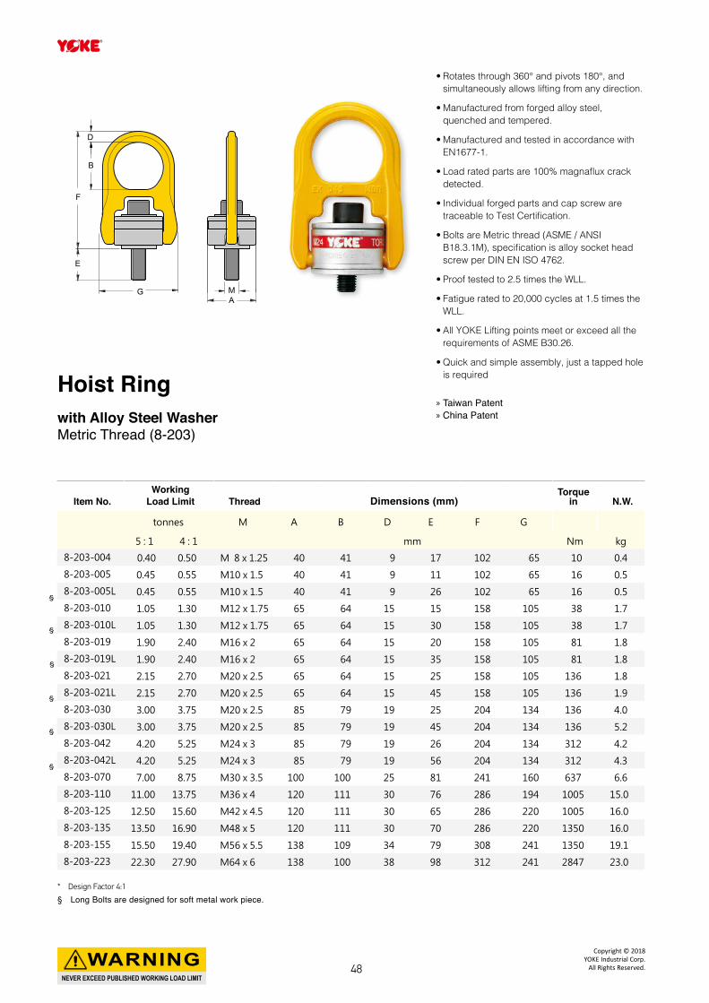
Hoist Ringwith Alloy Steel WasherMetric Thread (8-203)
» Taiwan Patent » China Patent
F
E
MA
G
D
B
§
§
§
§
§
§
* Design Factor 4:1
§ Long Bolts are designed for soft metal work piece.
• Rotates through 360° and pivots 180°, and simultaneously allows lifting from any direction.
• Manufactured from forged alloy steel, quenched and tempered.
• Manufactured and tested in accordance with EN1677-1.
• Load rated parts are 100% magnaflux crack detected.
• Individual forged parts and cap screw are traceable to Test Certification.
• Bolts are Metric thread (ASME / ANSI B18.3.1M), specification is alloy socket head screw per DIN EN ISO 4762.
• Proof tested to 2.5 times the WLL.
• Fatigue rated to 20,000 cycles at 1.5 times the WLL.
• All YOKE Lifting points meet or exceed all the requirements of ASME B30.26.
• Quick and simple assembly, just a tapped hole is required
NEVER EXCEED PUBLISHED WORKING LOAD LIMIT
WARNINGCopyright © 2018
YOKE Industrial Corp.All Rights Reserved.48
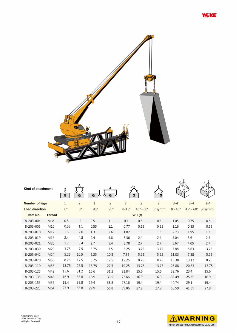
Kind of attachment
Number of legs 1 2 1 2 2 2 2 3-4 3-4 3-4
Load direction 0° 0° 90° 90° 0-45° 45° - 60° unsymm. 0 - 45° 45° - 60° unsymm.
Item No. Thread WLL(t)
8-203-004 M 8 0.5 1 0.5 1 0.7 0.5 0.5 1.05 0.75 0.5
8-203-005 M10 0.55 1.1 0.55 1.1 0.77 0.55 0.55 1.16 0.83 0.55
8-203-010 M12 1.3 2.6 1.3 2.6 1.82 1.3 1.3 2.73 1.95 1.3
8-203-019 M16 2.4 4.8 2.4 4.8 3.36 2.4 2.4 5.04 3.6 2.4
8-203-021 M20 2.7 5.4 2.7 5.4 3.78 2.7 2.7 5.67 4.05 2.7
8-203-030 M20 3.75 7.5 3.75 7.5 5.25 3.75 3.75 7.88 5.63 3.75
8-203-042 M24 5.25 10.5 5.25 10.5 7.35 5.25 5.25 11.03 7.88 5.25
8-203-070 M30 8.75 17.5 8.75 17.5 12.25 8.75 8.75 18.38 13.13 8.75
8-203-110 M36 13.75 27.5 13.75 27.5 19.25 13.75 13.75 28.88 20.63 13.75
8-203-125 M42 15.6 31.2 15.6 31.2 21.84 15.6 15.6 32.76 23.4 15.6
8-203-135 M48 16.9 33.8 16.9 33.5 23.66 16.9 16.9 35.49 25.35 16.9
8-203-155 M56 19.4 38.8 19.4 38.8 27.16 19.4 19.4 40.74 29.1 19.4
8-203-223 M64 27.9 55.8 27.9 55.8 39.06 27.9 27.9 58.59 41.85 27.9
NEVER EXCEED PUBLISHED WORKING LOAD LIMIT
WARNINGCopyright © 2018 YOKE Industrial Corp.All Rights Reserved. 49
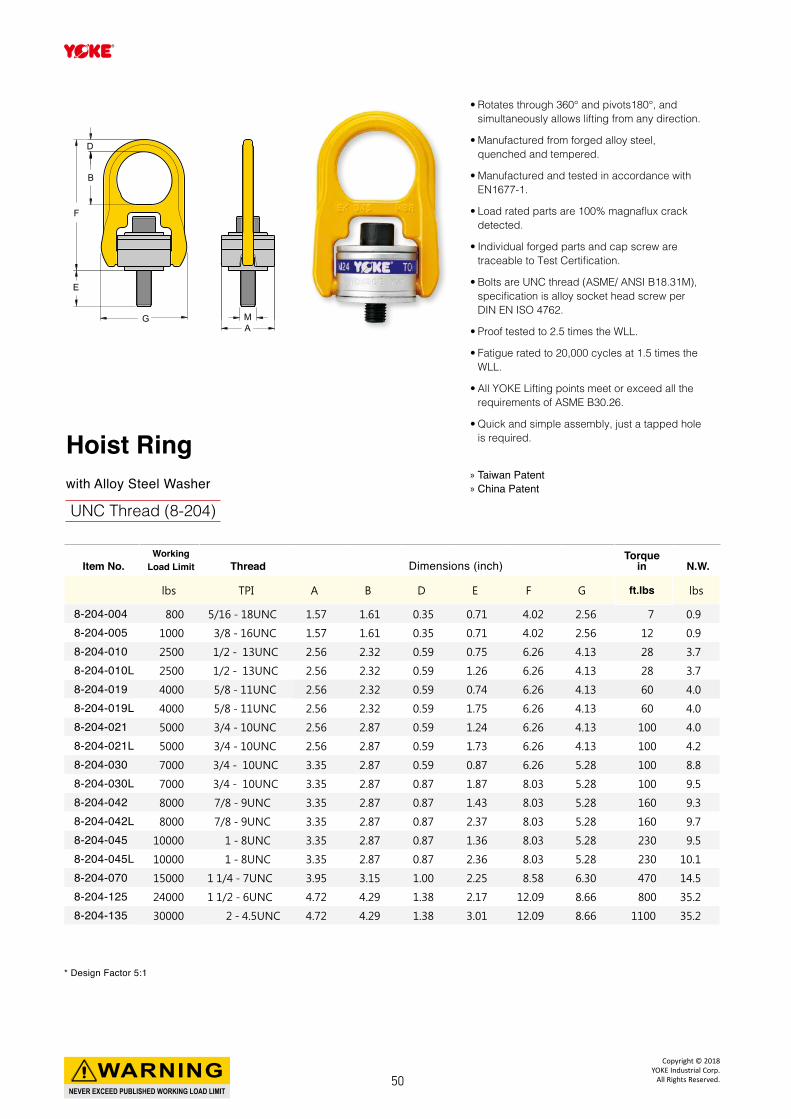
Item No.Working
Load Limit Thread Dimensions (inch)Torque
in N.W.
lbs TPI A B D E F G ft.lbs lbs
8-204-004 800 5/16 - 18UNC 1.57 1.61 0.35 0.71 4.02 2.56 7 0.9
8-204-005 1000 3/8 - 16UNC 1.57 1.61 0.35 0.71 4.02 2.56 12 0.9
8-204-010 2500 1/2 - 13UNC 2.56 2.32 0.59 0.75 6.26 4.13 28 3.7
8-204-010L 2500 1/2 - 13UNC 2.56 2.32 0.59 1.26 6.26 4.13 28 3.7
8-204-019 4000 5/8 - 11UNC 2.56 2.32 0.59 0.74 6.26 4.13 60 4.0
8-204-019L 4000 5/8 - 11UNC 2.56 2.32 0.59 1.75 6.26 4.13 60 4.0
8-204-021 5000 3/4 - 10UNC 2.56 2.87 0.59 1.24 6.26 4.13 100 4.0
8-204-021L 5000 3/4 - 10UNC 2.56 2.87 0.59 1.73 6.26 4.13 100 4.2
8-204-030 7000 3/4 - 10UNC 3.35 2.87 0.59 0.87 6.26 5.28 100 8.8
8-204-030L 7000 3/4 - 10UNC 3.35 2.87 0.87 1.87 8.03 5.28 100 9.5
8-204-042 8000 7/8 - 9UNC 3.35 2.87 0.87 1.43 8.03 5.28 160 9.3
8-204-042L 8000 7/8 - 9UNC 3.35 2.87 0.87 2.37 8.03 5.28 160 9.7
8-204-045 10000 1 - 8UNC 3.35 2.87 0.87 1.36 8.03 5.28 230 9.5
8-204-045L 10000 1 - 8UNC 3.35 2.87 0.87 2.36 8.03 5.28 230 10.1
8-204-070 15000 1 1/4 - 7UNC 3.95 3.15 1.00 2.25 8.58 6.30 470 14.5
8-204-125 24000 1 1/2 - 6UNC 4.72 4.29 1.38 2.17 12.09 8.66 800 35.2
8-204-135 30000 2 - 4.5UNC 4.72 4.29 1.38 3.01 12.09 8.66 1100 35.2
Hoist Ringwith Alloy Steel Washer
UNC Thread (8-204)
» Taiwan Patent » China Patent
F
E
MA
G
D
B
* Design Factor 5:1
• Rotates through 360° and pivots180°, and simultaneously allows lifting from any direction.
• Manufactured from forged alloy steel, quenched and tempered.
• Manufactured and tested in accordance with EN1677-1.
• Load rated parts are 100% magnaflux crack detected.
• Individual forged parts and cap screw are traceable to Test Certification.
• Bolts are UNC thread (ASME/ ANSI B18.31M), specification is alloy socket head screw per DIN EN ISO 4762.
• Proof tested to 2.5 times the WLL.
• Fatigue rated to 20,000 cycles at 1.5 times the WLL.
• All YOKE Lifting points meet or exceed all the requirements of ASME B30.26.
• Quick and simple assembly, just a tapped hole is required.
NEVER EXCEED PUBLISHED WORKING LOAD LIMIT
WARNINGCopyright © 2018
YOKE Industrial Corp.All Rights Reserved.50
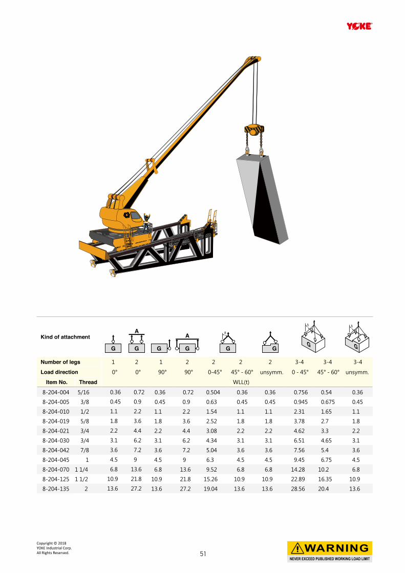
Kind of attachment
Number of legs 1 2 1 2 2 2 2 3-4 3-4 3-4
Load direction 0° 0° 90° 90° 0-45° 45° - 60° unsymm. 0 - 45° 45° - 60° unsymm.
Item No. Thread WLL(t)
8-204-004 5/16 0.36 0.72 0.36 0.72 0.504 0.36 0.36 0.756 0.54 0.36
8-204-005 3/8 0.45 0.9 0.45 0.9 0.63 0.45 0.45 0.945 0.675 0.45
8-204-010 1/2 1.1 2.2 1.1 2.2 1.54 1.1 1.1 2.31 1.65 1.1
8-204-019 5/8 1.8 3.6 1.8 3.6 2.52 1.8 1.8 3.78 2.7 1.8
8-204-021 3/4 2.2 4.4 2.2 4.4 3.08 2.2 2.2 4.62 3.3 2.2
8-204-030 3/4 3.1 6.2 3.1 6.2 4.34 3.1 3.1 6.51 4.65 3.1
8-204-042 7/8 3.6 7.2 3.6 7.2 5.04 3.6 3.6 7.56 5.4 3.6
8-204-045 1 4.5 9 4.5 9 6.3 4.5 4.5 9.45 6.75 4.5
8-204-070 1 1/4 6.8 13.6 6.8 13.6 9.52 6.8 6.8 14.28 10.2 6.8
8-204-125 1 1/2 10.9 21.8 10.9 21.8 15.26 10.9 10.9 22.89 16.35 10.9
8-204-135 2 13.6 27.2 13.6 27.2 19.04 13.6 13.6 28.56 20.4 13.6
NEVER EXCEED PUBLISHED WORKING LOAD LIMIT
WARNINGCopyright © 2018 YOKE Industrial Corp.All Rights Reserved. 51
52
Copyright © 2017
YOKE Industrial Corp.
All Rights Reserved.
Y PSAAnchor Point for Personal Protective Equipment
53
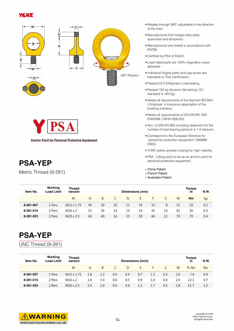
• Rotates through 360° adjustable in the direction of the load.
• Manufactured from forged alloy steel, quenched and tempered.
• Manufactured and tested in accordance with EN795.
• Certified by PSA of DGUV.
• Load rated parts are 100% magnaflux crack detected.
• Individual forged parts and cap screw are traceable to Test Certification.
• Passed 22.2 KN/person Load testing.
• Passed 150 kg dynamic fall testing ( EU standard is 100 kg).
• Meets all requirements of the German BG BAU ( Employer ́s insurance association of the building industry).
• Meets all requirements of DIN EN795, DIN EN50308, OSHA1926.502.
• Acc. to DIN EN 365 including statement for the number of load bearing persons is 1-2 persons.
• Correspond to the European Directive for “personnel protection equipment” (89/686/EWG).
• YOKE yellow powder coating for high visibility.
• PSA - Lifting point to be as an anchor point for personal protective equipment.
Item No.Working
Load LimitThread version Dimensions (mm)
Torquein N.W.
M A B C D E F S W Nm kg
8-281-007 1 Pers M12 x 1.75 45 30 10 11 19 33 8 52 10 0.2
8-281-015 2 Pers M16 x 2 52 35 14 13 24 35 10 61 30 0.3
8-281-023 2 Pers M20 x 2.5 60 40 16 15 30 44 12 70 70 0.6
Item No.Working
Load LimitThread version Dimensions (inch)
Torquein N.W.
M A B C D E F S W ft. lbs lbs
8-281-007 1 Pers M12 x 1.75 1.8 1.2 0.4 0.4 0.7 1.3 0.3 2.0 7.4 0.4
8-281-015 2 Pers M16 x 2 2.0 1.4 0.6 0.5 0.9 1.4 0.4 2.4 22.1 0.7
8-281-023 2 Pers M20 x 2.5 2.4 1.6 0.6 0.6 1.2 1.7 0.5 2.8 51.7 1.3
360° Rotation
CC
DD
AA
FF
EE
MM
BB
WW
SS
PSA-YEPMetric Thread (8-281)
PSA-YEPUNC Thread (8-281)
» China Patent » French Patent » Australian Patent
Y PSAAnchor Point for Personal Protective Equipment
NEVER EXCEED PUBLISHED WORKING LOAD LIMIT
WARNINGCopyright © 2018
YOKE Industrial Corp.All Rights Reserved.54
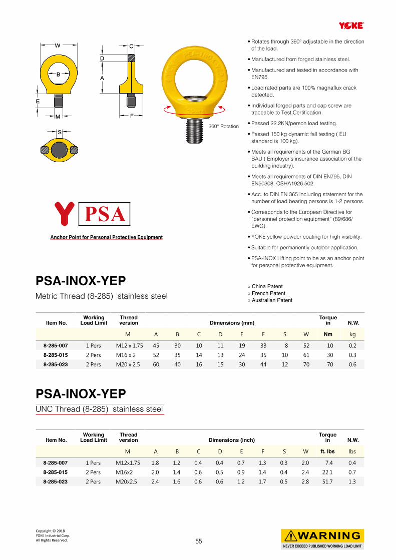
• Rotates through 360° adjustable in the direction of the load.
• Manufactured from forged stainless steel.
• Manufactured and tested in accordance with EN795.
• Load rated parts are 100% magnaflux crack detected.
• Individual forged parts and cap screw are traceable to Test Certification.
• Passed 22.2KN/person load testing.
• Passed 150 kg dynamic fall testing ( EU standard is 100 kg).
• Meets all requirements of the German BG BAU ( Employer’s insurance association of the building industry).
• Meets all requirements of DIN EN795, DIN EN50308, OSHA1926.502.
• Acc. to DIN EN 365 including statement for the number of load bearing persons is 1-2 persons.
• Corresponds to the European Directive for “personnel protection equipment” (89/686/EWG).
• YOKE yellow powder coating for high visibility.
• Suitable for permanently outdoor application.
• PSA-INOX Lifting point to be as an anchor point for personal protective equipment.
Item No.Working
Load LimitThread version Dimensions (mm)
Torquein N.W.
M A B C D E F S W Nm kg
8-285-007 1 Pers M12 x 1.75 45 30 10 11 19 33 8 52 10 0.2
8-285-015 2 Pers M16 x 2 52 35 14 13 24 35 10 61 30 0.3
8-285-023 2 Pers M20 x 2.5 60 40 16 15 30 44 12 70 70 0.6
Item No.Working
Load LimitThread version Dimensions (inch)
Torquein N.W.
M A B C D E F S W ft. lbs lbs
8-285-007 1 Pers M12x1.75 1.8 1.2 0.4 0.4 0.7 1.3 0.3 2.0 7.4 0.4
8-285-015 2 Pers M16x2 2.0 1.4 0.6 0.5 0.9 1.4 0.4 2.4 22.1 0.7
8-285-023 2 Pers M20x2.5 2.4 1.6 0.6 0.6 1.2 1.7 0.5 2.8 51.7 1.3
360° Rotation
PSA-INOX-YEPMetric Thread (8-285) stainless steel
CC
DD
AA
FF
EE
MM
BB
WW
SS
» China Patent » French Patent » Australian Patent
Y PSAAnchor Point for Personal Protective Equipment
PSA-INOX-YEPUNC Thread (8-285) stainless steel
NEVER EXCEED PUBLISHED WORKING LOAD LIMIT
WARNINGCopyright © 2018 YOKE Industrial Corp.All Rights Reserved. 55
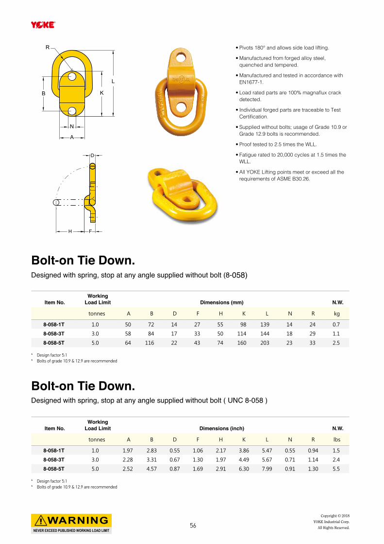
• Pivots 180° and allows side load lifting.
• Manufactured from forged alloy steel, quenched and tempered.
• Manufactured and tested in accordance with EN1677-1.
• Load rated parts are 100% magnaflux crack detected.
• Individual forged parts are traceable to Test Certification.
• Supplied without bolts; usage of Grade 10.9 or Grade 12.9 bolts is recommended.
• Proof tested to 2.5 times the WLL.
• Fatigue rated to 20,000 cycles at 1.5 times the WLL.
• All YOKE Lifting points meet or exceed all the requirements of ASME B30.26.
* Design factor 5:1* Bolts of grade 10.9 & 12.9 are recommended
Item No.Working
Load Limit Dimensions (mm) N.W.
tonnes A B D F H K L N R kg
8-058-1T 1.0 50 72 14 27 55 98 139 14 24 0.7
8-058-3T 3.0 58 84 17 33 50 114 144 18 29 1.1
8-058-5T 5.0 64 116 22 43 74 160 203 23 33 2.5
Bolt-on Tie Down. Designed with spring, stop at any angle supplied without bolt (8-058)
A
N
K
L
B
R
H F
D
* Design factor 5:1* Bolts of grade 10.9 & 12.9 are recommended
Item No.Working
Load Limit Dimensions (inch) N.W.
tonnes A B D F H K L N R lbs
8-058-1T 1.0 1.97 2.83 0.55 1.06 2.17 3.86 5.47 0.55 0.94 1.5
8-058-3T 3.0 2.28 3.31 0.67 1.30 1.97 4.49 5.67 0.71 1.14 2.4
8-058-5T 5.0 2.52 4.57 0.87 1.69 2.91 6.30 7.99 0.91 1.30 5.5
Bolt-on Tie Down. Designed with spring, stop at any angle supplied without bolt ( UNC 8-058 )
NEVER EXCEED PUBLISHED WORKING LOAD LIMIT
WARNING Copyright © 2018
YOKE Industrial Corp.
All Rights Reserved.56

Weld-on Lifting Points
NEVER EXCEED PUBLISHED WORKING LOAD LIMIT
WARNINGCopyright © 2018 YOKE Industrial Corp.All Rights Reserved. 57
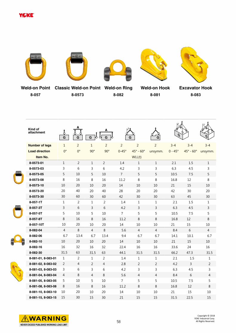
Kind of attachment
Number of legs 1 2 1 2 2 2 2 3-4 3-4 3-4
Load direction 0° 0° 90° 90° 0-45° 45° - 60° unsymm. 0 - 45° 45° - 60° unsymm.
Item No. WLL(t)
8-0573-01 1 2 1 2 1.4 1 1 2.1 1.5 1
8-0573-03 3 6 3 6 4.2 3 3 6.3 4.5 3
8-0573-05 5 10 5 10 7 5 5 10.5 7.5 5
8-0573-08 8 16 8 16 11.2 8 8 16.8 12 8
8-0573-10 10 20 10 20 14 10 10 21 15 10
8-0573-20 20 40 20 40 28 20 20 42 30 20
8-0573-30 30 60 30 60 42 30 30 63 45 30
8-057-1T 1 2 1 2 1.4 1 1 2.1 1.5 1
8-057-3T 3 6 3 6 4.2 3 3 6.3 4.5 3
8-057-5T 5 10 5 10 7 5 5 10.5 7.5 5
8-057-8T 8 16 8 16 11.2 8 8 16.8 12 8
8-057-10T 10 20 10 20 14 10 10 21 15 10
8-082-04 4 8 4 8 5.6 4 4 8.4 6 4
8-082-06 6.7 13.4 6.7 13.4 9.4 6.7 6.7 14.1 10.1 6.7
8-082-10 10 20 10 20 14 10 10 21 15 10
8-082-16 16 32 16 32 22.4 16 16 33.6 24 16
8-082-30 31.5 63 31.5 63 44.1 31.5 31.5 66.2 47.3 31.5
8-081-01, 8-083-01 1 2 1 2 1.4 1 1 2.1 1.5 1
8-081-02, 8-083-02 2 4 2 4 2.8 2 2 4.2 3 2
8-081-03, 8-083-03 3 6 3 6 4.2 3 3 6.3 4.5 3
8-081-04, 8-083-04 4 8 4 8 5.6 4 4 8.4 6 4
8-081-05, 8-083-05 5 10 5 10 7 5 5 10.5 7.5 5
8-081-08, 8-083-08 8 16 8 16 11.2 8 8 16.8 12 8
8-081-10, 8-083-10 10 20 10 20 14 10 10 21 15 10
8-081-15, 8-083-15 15 30 15 30 21 15 15 31.5 22.5 15
Classic Weld-on Point8-0573
Weld-on Ring8-082
Weld-on Point8-057
Weld-on Hook8-081
Excavator Hook8-083
NEVER EXCEED PUBLISHED WORKING LOAD LIMIT
WARNINGCopyright © 2018
YOKE Industrial Corp.All Rights Reserved.58
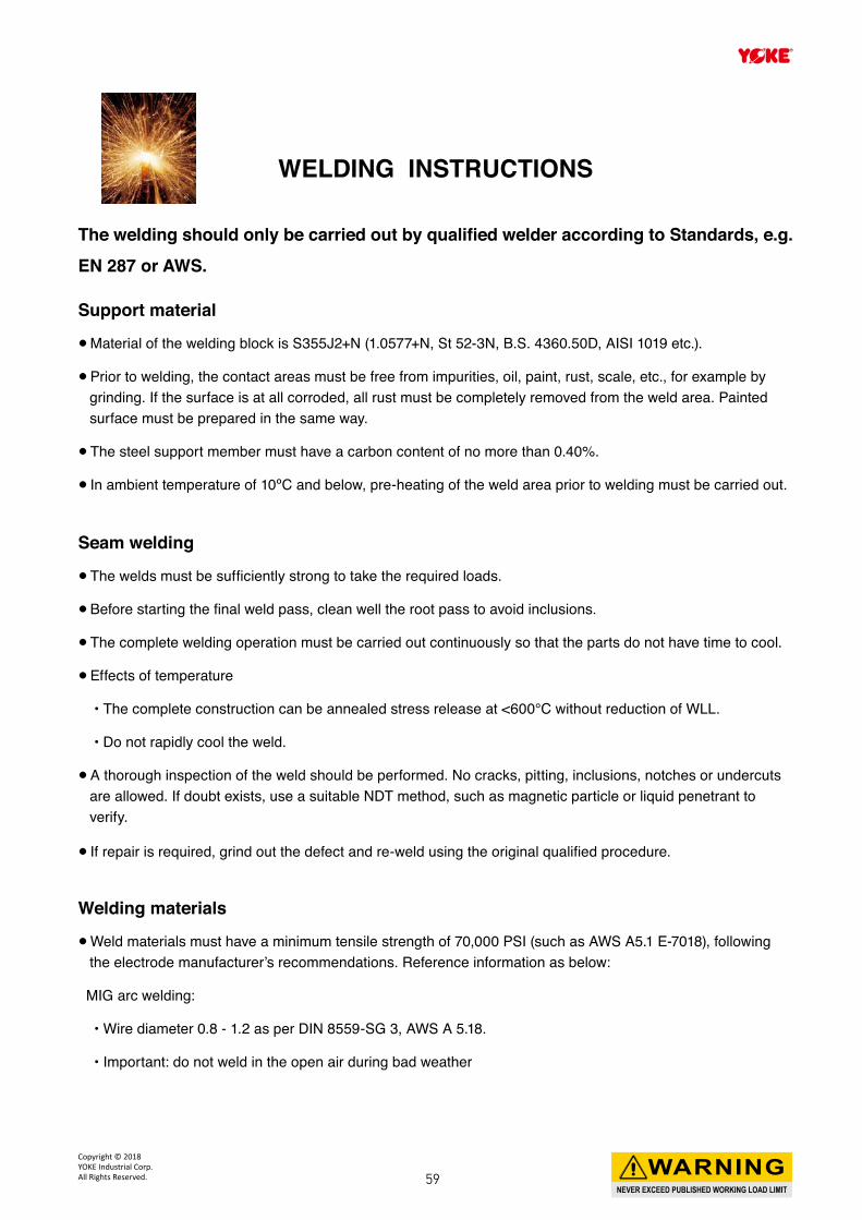
WELDING INSTRUCTIONS
The welding should only be carried out by qualified welder according to Standards, e.g. EN 287 or AWS.
Support material●● Material of the welding block is S355J2+N (1.0577+N, St 52-3N, B.S. 4360.50D, AISI 1019 etc.).
●● Prior to welding, the contact areas must be free from impurities, oil, paint, rust, scale, etc., for example by grinding. If the surface is at all corroded, all rust must be completely removed from the weld area. Painted surface must be prepared in the same way.
●● The steel support member must have a carbon content of no more than 0.40%.
●● In ambient temperature of 10ºC and below, pre-heating of the weld area prior to welding must be carried out.
Seam welding●● The welds must be sufficiently strong to take the required loads.
●● Before starting the final weld pass, clean well the root pass to avoid inclusions.
●● The complete welding operation must be carried out continuously so that the parts do not have time to cool.
●● Effects of temperature
• The complete construction can be annealed stress release at <600°C without reduction of WLL.
• Do not rapidly cool the weld.
●● A thorough inspection of the weld should be performed. No cracks, pitting, inclusions, notches or undercuts are allowed. If doubt exists, use a suitable NDT method, such as magnetic particle or liquid penetrant to verify.
●● If repair is required, grind out the defect and re-weld using the original qualified procedure.
Welding materials●● Weld materials must have a minimum tensile strength of 70,000 PSI (such as AWS A5.1 E-7018), following the electrode manufacturer’s recommendations. Reference information as below:
MIG arc welding:
• Wire diameter 0.8 - 1.2 as per DIN 8559-SG 3, AWS A 5.18.
• Important: do not weld in the open air during bad weather
NEVER EXCEED PUBLISHED WORKING LOAD LIMIT
WARNINGCopyright © 2018 YOKE Industrial Corp.All Rights Reserved. 59
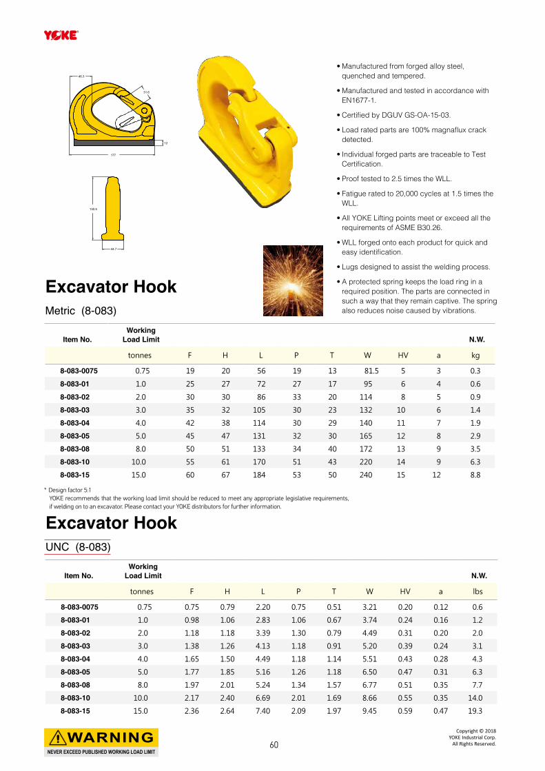
• Manufactured from forged alloy steel, quenched and tempered.
• Manufactured and tested in accordance with EN1677-1.
• Certified by DGUV GS-OA-15-03.
• Load rated parts are 100% magnaflux crack detected.
• Individual forged parts are traceable to Test Certification.
• Proof tested to 2.5 times the WLL.
• Fatigue rated to 20,000 cycles at 1.5 times the WLL.
• All YOKE Lifting points meet or exceed all the requirements of ASME B30.26.
• WLL forged onto each product for quick and easy identification.
• Lugs designed to assist the welding process.
• A protected spring keeps the load ring in a required position. The parts are connected in such a way that they remain captive. The spring also reduces noise caused by vibrations.
* Design factor 5:1YOKE recommends that the working load limit should be reduced to meet any appropriate legislative requirements, if welding on to an excavator. Please contact your YOKE distributors for further information.
Item No.Working
Load Limit N.W.
tonnes F H L P T W HV a kg
8-083-0075 0.75 19 20 56 19 13 81.5 5 3 0.3
8-083-01 1.0 25 27 72 27 17 95 6 4 0.6
8-083-02 2.0 30 30 86 33 20 114 8 5 0.9
8-083-03 3.0 35 32 105 30 23 132 10 6 1.4
8-083-04 4.0 42 38 114 30 29 140 11 7 1.9
8-083-05 5.0 45 47 131 32 30 165 12 8 2.9
8-083-08 8.0 50 51 133 34 40 172 13 9 3.5
8-083-10 10.0 55 61 170 51 43 220 14 9 6.3
8-083-15 15.0 60 67 184 53 50 240 15 12 8.8
Excavator HookMetric (8-083)
Item No.Working
Load Limit N.W.
tonnes F H L P T W HV a lbs
8-083-0075 0.75 0.75 0.79 2.20 0.75 0.51 3.21 0.20 0.12 0.6
8-083-01 1.0 0.98 1.06 2.83 1.06 0.67 3.74 0.24 0.16 1.2
8-083-02 2.0 1.18 1.18 3.39 1.30 0.79 4.49 0.31 0.20 2.0
8-083-03 3.0 1.38 1.26 4.13 1.18 0.91 5.20 0.39 0.24 3.1
8-083-04 4.0 1.65 1.50 4.49 1.18 1.14 5.51 0.43 0.28 4.3
8-083-05 5.0 1.77 1.85 5.16 1.26 1.18 6.50 0.47 0.31 6.3
8-083-08 8.0 1.97 2.01 5.24 1.34 1.57 6.77 0.51 0.35 7.7
8-083-10 10.0 2.17 2.40 6.69 2.01 1.69 8.66 0.55 0.35 14.0
8-083-15 15.0 2.36 2.64 7.40 2.09 1.97 9.45 0.59 0.47 19.3
Excavator HookUNC (8-083)
130.5
44.7
177
46.3
12
31.6
NEVER EXCEED PUBLISHED WORKING LOAD LIMIT
WARNINGCopyright © 2018
YOKE Industrial Corp.All Rights Reserved.60
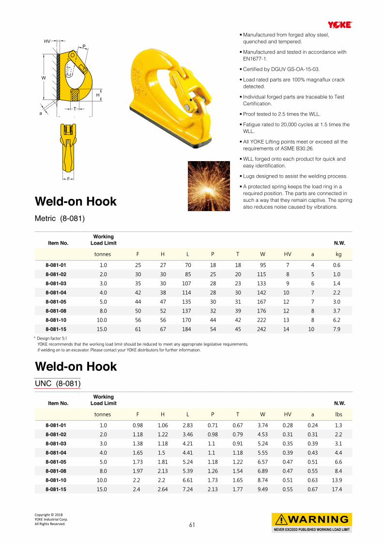
• Manufactured from forged alloy steel, quenched and tempered.
• Manufactured and tested in accordance with EN1677-1.
• Certified by DGUV GS-OA-15-03.
• Load rated parts are 100% magnaflux crack detected.
• Individual forged parts are traceable to Test Certification.
• Proof tested to 2.5 times the WLL.
• Fatigue rated to 20,000 cycles at 1.5 times the WLL.
• All YOKE Lifting points meet or exceed all the requirements of ASME B30.26.
• WLL forged onto each product for quick and easy identification.
• Lugs designed to assist the welding process.
• A protected spring keeps the load ring in a required position. The parts are connected in such a way that they remain captive. The spring also reduces noise caused by vibrations.
* Design factor 5:1YOKE recommends that the working load limit should be reduced to meet any appropriate legislative requirements, if welding on to an excavator. Please contact your YOKE distributors for further information.
Item No.Working
Load Limit N.W.
tonnes F H L P T W HV a kg
8-081-01 1.0 25 27 70 18 18 95 7 4 0.6
8-081-02 2.0 30 30 85 25 20 115 8 5 1.0
8-081-03 3.0 35 30 107 28 23 133 9 6 1.4
8-081-04 4.0 42 38 114 28 30 142 10 7 2.2
8-081-05 5.0 44 47 135 30 31 167 12 7 3.0
8-081-08 8.0 50 52 137 32 39 176 12 8 3.7
8-081-10 10.0 56 56 170 44 42 222 13 8 6.2
8-081-15 15.0 61 67 184 54 45 242 14 10 7.9
HV
W
aL
T
H
P
F
Weld-on HookMetric (8-081)
Item No.Working
Load Limit N.W.
tonnes F H L P T W HV a lbs
8-081-01 1.0 0.98 1.06 2.83 0.71 0.67 3.74 0.28 0.24 1.3
8-081-02 2.0 1.18 1.22 3.46 0.98 0.79 4.53 0.31 0.31 2.2
8-081-03 3.0 1.38 1.18 4.21 1.1 0.91 5.24 0.35 0.39 3.1
8-081-04 4.0 1.65 1.5 4.41 1.1 1.18 5.55 0.39 0.43 4.4
8-081-05 5.0 1.73 1.81 5.24 1.18 1.22 6.57 0.47 0.51 6.6
8-081-08 8.0 1.97 2.13 5.39 1.26 1.54 6.89 0.47 0.55 8.4
8-081-10 10.0 2.2 2.2 6.61 1.73 1.65 8.74 0.51 0.63 13.9
8-081-15 15.0 2.4 2.64 7.24 2.13 1.77 9.49 0.55 0.67 17.4
Weld-on HookUNC (8-081)
NEVER EXCEED PUBLISHED WORKING LOAD LIMIT
WARNINGCopyright © 2018 YOKE Industrial Corp.All Rights Reserved. 61
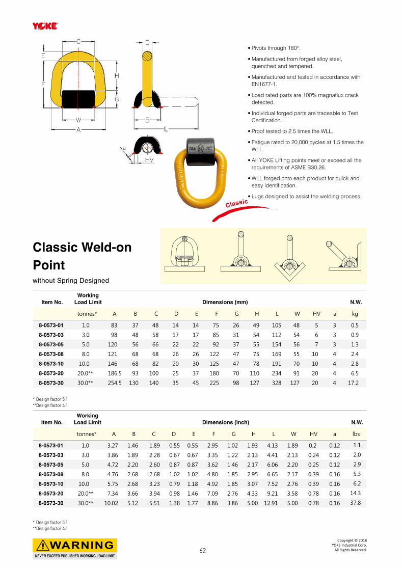
* Design factor 5:1**Design factor 4:1
• Pivots through 180°.
• Manufactured from forged alloy steel, quenched and tempered.
• Manufactured and tested in accordance with EN1677-1.
• Load rated parts are 100% magnaflux crack detected.
• Individual forged parts are traceable to Test Certification.
• Proof tested to 2.5 times the WLL.
• Fatigue rated to 20,000 cycles at 1.5 times the WLL.
• All YOKE Lifting points meet or exceed all the requirements of ASME B30.26.
• WLL forged onto each product for quick and easy identification.
• Lugs designed to assist the welding process.
Item No.Working
Load Limit Dimensions (mm) N.W.
tonnes* A B C D E F G H L W HV a kg
8-0573-01 1.0 83 37 48 14 14 75 26 49 105 48 5 3 0.5
8-0573-03 3.0 98 48 58 17 17 85 31 54 112 54 6 3 0.9
8-0573-05 5.0 120 56 66 22 22 92 37 55 154 56 7 3 1.3
8-0573-08 8.0 121 68 68 26 26 122 47 75 169 55 10 4 2.4
8-0573-10 10.0 146 68 82 20 30 125 47 78 191 70 10 4 2.8
8-0573-20 20.0** 186.5 93 100 25 37 180 70 110 234 91 20 4 6.5
8-0573-30 30.0** 254.5 130 140 35 45 225 98 127 328 127 20 4 17.2
Classic Weld-on Pointwithout Spring Designed
a
Classic
* Design factor 5:1**Design factor 4:1
Item No.Working
Load Limit Dimensions (inch) N.W.
tonnes* A B C D E F G H L W HV a lbs
8-0573-01 1.0 3.27 1.46 1.89 0.55 0.55 2.95 1.02 1.93 4.13 1.89 0.2 0.12 1.1
8-0573-03 3.0 3.86 1.89 2.28 0.67 0.67 3.35 1.22 2.13 4.41 2.13 0.24 0.12 2.0
8-0573-05 5.0 4.72 2.20 2.60 0.87 0.87 3.62 1.46 2.17 6.06 2.20 0.25 0.12 2.9
8-0573-08 8.0 4.76 2.68 2.68 1.02 1.02 4.80 1.85 2.95 6.65 2.17 0.39 0.16 5.3
8-0573-10 10.0 5.75 2.68 3.23 0.79 1.18 4.92 1.85 3.07 7.52 2.76 0.39 0.16 6.2
8-0573-20 20.0** 7.34 3.66 3.94 0.98 1.46 7.09 2.76 4.33 9.21 3.58 0.78 0.16 14.3
8-0573-30 30.0** 10.02 5.12 5.51 1.38 1.77 8.86 3.86 5.00 12.91 5.00 0.78 0.16 37.8
NEVER EXCEED PUBLISHED WORKING LOAD LIMIT
WARNINGCopyright © 2018
YOKE Industrial Corp.All Rights Reserved.62
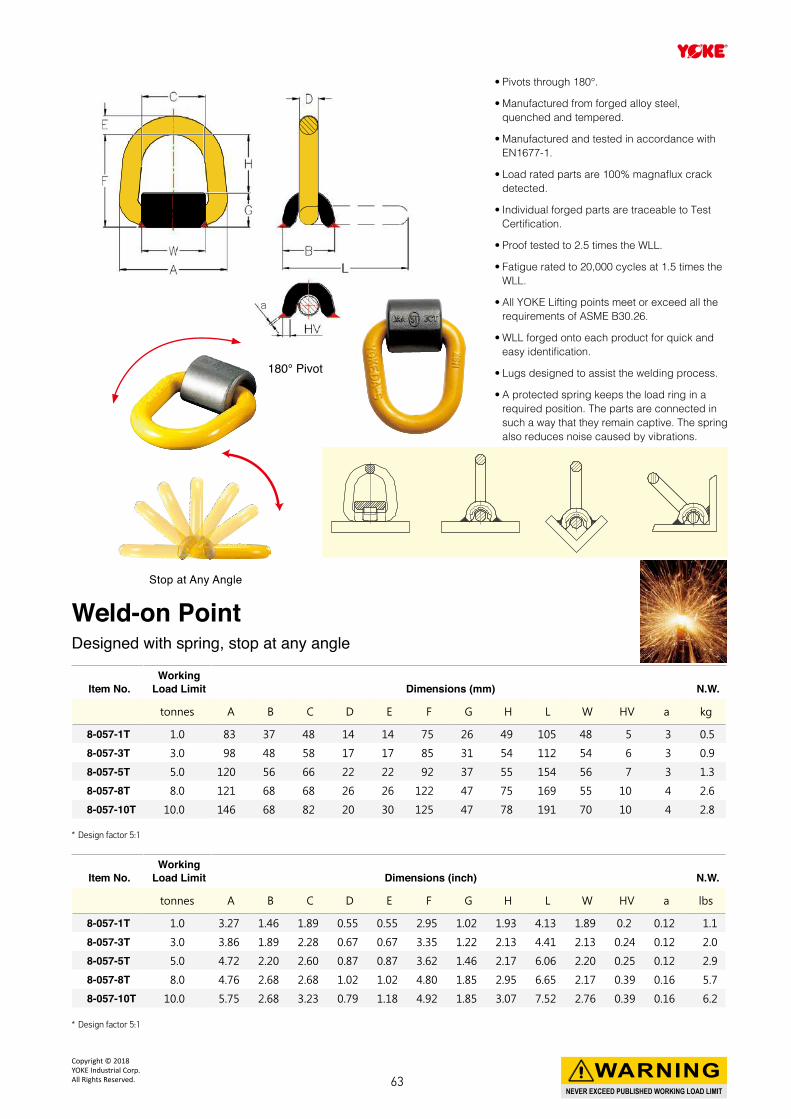
a
• Pivots through 180°.
• Manufactured from forged alloy steel, quenched and tempered.
• Manufactured and tested in accordance with EN1677-1.
• Load rated parts are 100% magnaflux crack detected.
• Individual forged parts are traceable to Test Certification.
• Proof tested to 2.5 times the WLL.
• Fatigue rated to 20,000 cycles at 1.5 times the WLL.
• All YOKE Lifting points meet or exceed all the requirements of ASME B30.26.
• WLL forged onto each product for quick and easy identification.
• Lugs designed to assist the welding process.
• A protected spring keeps the load ring in a required position. The parts are connected in such a way that they remain captive. The spring also reduces noise caused by vibrations.
* Design factor 5:1
Item No.Working
Load Limit Dimensions (mm) N.W.
tonnes A B C D E F G H L W HV a kg
8-057-1T 1.0 83 37 48 14 14 75 26 49 105 48 5 3 0.5
8-057-3T 3.0 98 48 58 17 17 85 31 54 112 54 6 3 0.9
8-057-5T 5.0 120 56 66 22 22 92 37 55 154 56 7 3 1.3
8-057-8T 8.0 121 68 68 26 26 122 47 75 169 55 10 4 2.6
8-057-10T 10.0 146 68 82 20 30 125 47 78 191 70 10 4 2.8
Weld-on PointDesigned with spring, stop at any angle
180° Pivot
Stop at Any Angle
* Design factor 5:1
Item No.Working
Load Limit Dimensions (inch) N.W.
tonnes A B C D E F G H L W HV a lbs
8-057-1T 1.0 3.27 1.46 1.89 0.55 0.55 2.95 1.02 1.93 4.13 1.89 0.2 0.12 1.1
8-057-3T 3.0 3.86 1.89 2.28 0.67 0.67 3.35 1.22 2.13 4.41 2.13 0.24 0.12 2.0
8-057-5T 5.0 4.72 2.20 2.60 0.87 0.87 3.62 1.46 2.17 6.06 2.20 0.25 0.12 2.9
8-057-8T 8.0 4.76 2.68 2.68 1.02 1.02 4.80 1.85 2.95 6.65 2.17 0.39 0.16 5.7
8-057-10T 10.0 5.75 2.68 3.23 0.79 1.18 4.92 1.85 3.07 7.52 2.76 0.39 0.16 6.2
NEVER EXCEED PUBLISHED WORKING LOAD LIMIT
WARNINGCopyright © 2018 YOKE Industrial Corp.All Rights Reserved. 63
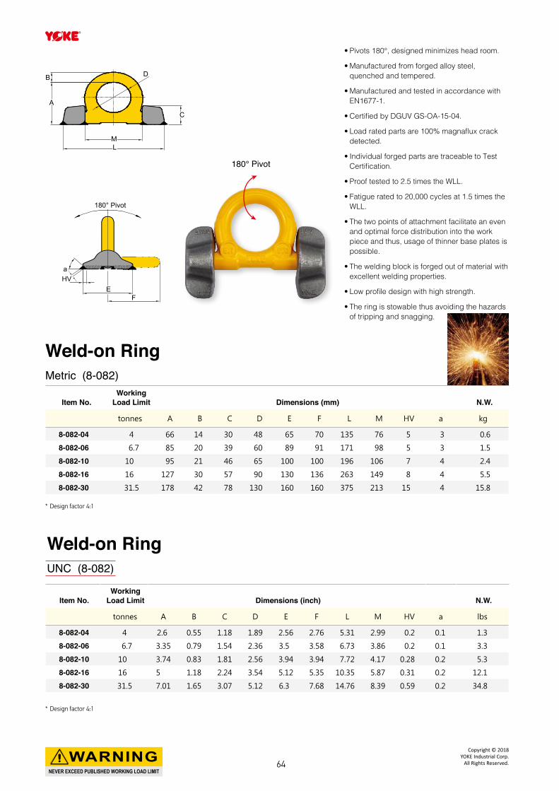
• Pivots 180°, designed minimizes head room.
• Manufactured from forged alloy steel, quenched and tempered.
• Manufactured and tested in accordance with EN1677-1.
• Certified by DGUV GS-OA-15-04.
• Load rated parts are 100% magnaflux crack detected.
• Individual forged parts are traceable to Test Certification.
• Proof tested to 2.5 times the WLL.
• Fatigue rated to 20,000 cycles at 1.5 times the WLL.
• The two points of attachment facilitate an even and optimal force distribution into the work piece and thus, usage of thinner base plates is possible.
• The welding block is forged out of material with excellent welding properties.
• Low profile design with high strength.
• The ring is stowable thus avoiding the hazards of tripping and snagging.
* Design factor 4:1
Item No.Working
Load Limit Dimensions (mm) N.W.
tonnes A B C D E F L M HV a kg
8-082-04 4 66 14 30 48 65 70 135 76 5 3 0.6
8-082-06 6.7 85 20 39 60 89 91 171 98 5 3 1.5
8-082-10 10 95 21 46 65 100 100 196 106 7 4 2.4
8-082-16 16 127 30 57 90 130 136 263 149 8 4 5.5
8-082-30 31.5 178 42 78 130 160 160 375 213 15 4 15.8
B
A
L
180° Pivot
FE
HVa
M
D
C
180° Pivot
Weld-on RingMetric (8-082)
* Design factor 4:1
Item No.Working
Load Limit Dimensions (inch) N.W.
tonnes A B C D E F L M HV a lbs
8-082-04 4 2.6 0.55 1.18 1.89 2.56 2.76 5.31 2.99 0.2 0.1 1.3
8-082-06 6.7 3.35 0.79 1.54 2.36 3.5 3.58 6.73 3.86 0.2 0.1 3.3
8-082-10 10 3.74 0.83 1.81 2.56 3.94 3.94 7.72 4.17 0.28 0.2 5.3
8-082-16 16 5 1.18 2.24 3.54 5.12 5.35 10.35 5.87 0.31 0.2 12.1
8-082-30 31.5 7.01 1.65 3.07 5.12 6.3 7.68 14.76 8.39 0.59 0.2 34.8
Weld-on RingUNC (8-082)
NEVER EXCEED PUBLISHED WORKING LOAD LIMIT
WARNINGCopyright © 2018
YOKE Industrial Corp.All Rights Reserved.64
NEVER EXCEED PUBLISHED WORKING LOAD LIMITWARNING
Copyright © 2018 YOKE Industrial Corp.All Rights Reserved. 65
NEVER EXCEED PUBLISHED WORKING LOAD LIMITWARNING
Copyright © 2018YOKE Industrial Corp.
All Rights Reserved.66
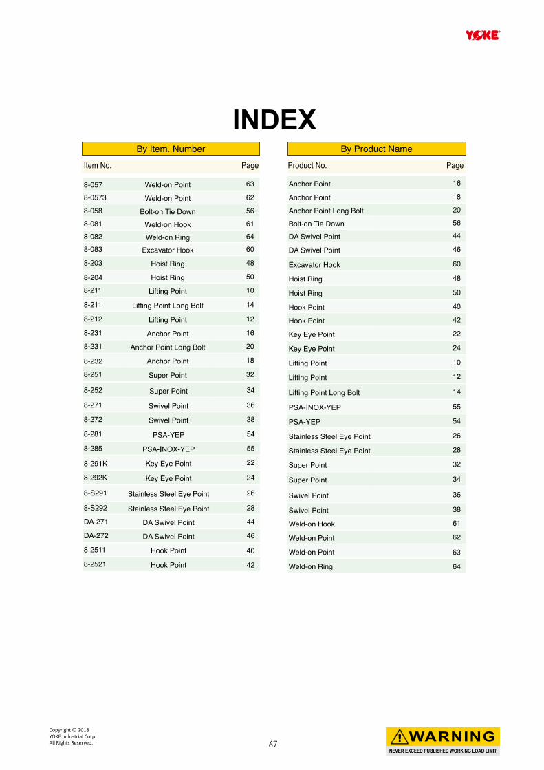
By Item. Number By Product Name
INDEX
8-057 Weld-on Point 63
8-0573 Weld-on Point 62
8-058 Bolt-on Tie Down 568-081 Weld-on Hook 618-082 Weld-on Ring 648-083 Excavator Hook 60
8-203 Hoist Ring 48
8-204 Hoist Ring 50
8-211 Lifting Point 10
8-211 Lifting Point Long Bolt 14
8-212 Lifting Point 12
8-231 Anchor Point 16
8-231 Anchor Point Long Bolt 20
8-232 Anchor Point 18
8-251 Super Point 32
Anchor Point 16
Anchor Point 18
Anchor Point Long Bolt 20
Bolt-on Tie Down 56
DA Swivel Point 44
DA Swivel Point 46
Excavator Hook 60
Hoist Ring 48
Hoist Ring 50
Hook Point 40
Hook Point 42
Key Eye Point 22
Key Eye Point 24
Lifting Point 10
Lifting Point 12
8-252 Super Point 34
8-271 Swivel Point 36
8-272 Swivel Point 38
8-281 PSA-YEP 54
8-285 PSA-INOX-YEP 55
8-291K Key Eye Point 22
8-292K Key Eye Point 24
8-S291 Stainless Steel Eye Point 26
8-S292 Stainless Steel Eye Point 28
DA-271 DA Swivel Point 44
DA-272 DA Swivel Point 46
8-2511 Hook Point 40
8-2521 Hook Point 42
Lifting Point Long Bolt 14
PSA-INOX-YEP 55
PSA-YEP 54
Stainless Steel Eye Point 26
Stainless Steel Eye Point 28
Super Point 32
Super Point 34
Swivel Point 36
Swivel Point 38
Weld-on Hook 61
Weld-on Point 62
Weld-on Point 63
Weld-on Ring 64
Item No. Page Product No. Page
NEVER EXCEED PUBLISHED WORKING LOAD LIMIT
WARNINGCopyright © 2018 YOKE Industrial Corp.All Rights Reserved. 67

www.yoke.net
An ISO 9001 Registered Company
YOKE INDUSTRIAL CORP. #39, 33rd Road,
Taichung Industrial Park,
Taichung 407,
TAIWAN
Tel:+886-4-2350-8088
Fax:+886-4-2350-1001
E-mail: [email protected]
VIDEO EN
Cat
alog
No.
8 -
2018
YP
/107
0126
/210
X29
7

![Home [] · WLL 1.5 t WLL 2.5 t WLL 3 t WLL 4 t WLL 5 t Four-ply polyester webstrop sling Feature . Four-ply polyester webbing sling with reinforced lifting eyes Working Load Limit](https://img.pdfslide.net/doc/110x75/5f158b4af74a9f786a0d29b3/home-wll-15-t-wll-25-t-wll-3-t-wll-4-t-wll-5-t-four-ply-polyester-webstrop.jpg)


![Z Wll }]X} PlíìXíôóóôlîïõíròðóôXîXîXìî](https://img.pdfslide.net/doc/110x75/620b0d8b518d8940297a4ed8/z-wll-x-plxlrxxx.jpg)