Embed Size (px)
Citation preview
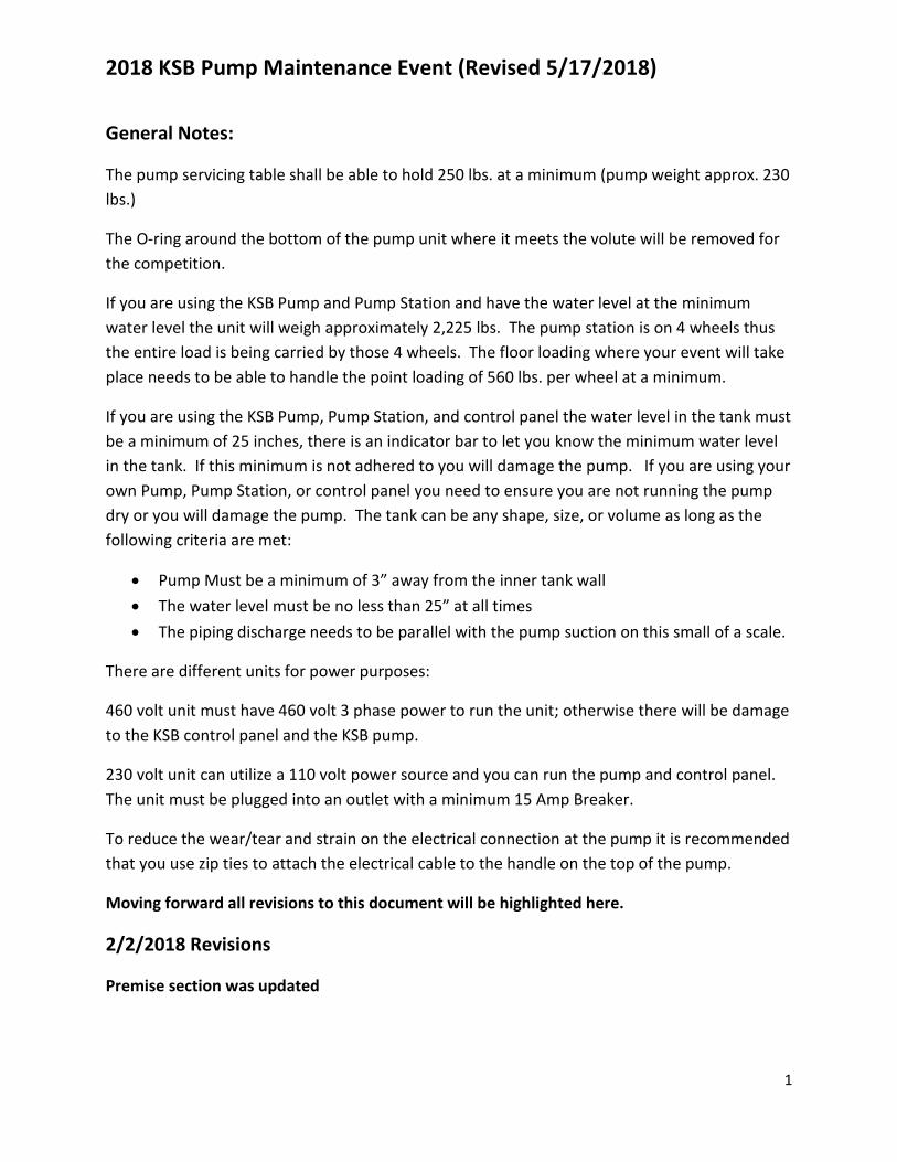
2018 KSB Pump Maintenance Event (Revised 5/17/2018)
1
General Notes:
The pump servicing table shall be able to hold 250 lbs. at a minimum (pump weight approx. 230 lbs.)
The O-ring around the bottom of the pump unit where it meets the volute will be removed for the competition.
If you are using the KSB Pump and Pump Station and have the water level at the minimum water level the unit will weigh approximately 2,225 lbs. The pump station is on 4 wheels thus the entire load is being carried by those 4 wheels. The floor loading where your event will take place needs to be able to handle the point loading of 560 lbs. per wheel at a minimum.
If you are using the KSB Pump, Pump Station, and control panel the water level in the tank must be a minimum of 25 inches, there is an indicator bar to let you know the minimum water level in the tank. If this minimum is not adhered to you will damage the pump. If you are using your own Pump, Pump Station, or control panel you need to ensure you are not running the pump dry or you will damage the pump. The tank can be any shape, size, or volume as long as the following criteria are met:
• Pump Must be a minimum of 3” away from the inner tank wall • The water level must be no less than 25” at all times • The piping discharge needs to be parallel with the pump suction on this small of a scale.
There are different units for power purposes:
460 volt unit must have 460 volt 3 phase power to run the unit; otherwise there will be damage to the KSB control panel and the KSB pump.
230 volt unit can utilize a 110 volt power source and you can run the pump and control panel. The unit must be plugged into an outlet with a minimum 15 Amp Breaker.
To reduce the wear/tear and strain on the electrical connection at the pump it is recommended that you use zip ties to attach the electrical cable to the handle on the top of the pump.
Moving forward all revisions to this document will be highlighted here.
2/2/2018 Revisions
Premise section was updated
2018 KSB Pump Maintenance Event (Revised 5/17/2018)
2
Added to the Walk Through/Preparation Section: “All tools and equipment must start and end on the equipment/tool table. You cannot install the rubber gasket for the new guide claw during the 5 minute setup time. The pump service table and the equipment/tool table may not be moved.”
Added to Task 10 Wet Well Servicing: “Install the old 9/16” nuts on the old guide rail bushings, nuts must be installed to at least be flush with the stud/bolt.”
4/3/2018 Revisions
Added to Task 1: Turn to Voltage setting (600 V˜)
Added to Task 2: On lift station control panel, turn Pump 1 Hand-Off-Auto (HOA) switch and Pump 2 HOA switch to “Off” position.
Added to Task 2: The Safety Supervisor must install a gang hasp, lock, and tag on the Main Disconnect switch. After the Safety Supervisor’s lock has been installed, all remaining team members can lock out as necessary
Added to Task 2: The Safety Supervisor must write the date and their initials on the label on the tag with the sharpie marker. It must be legible. It must be written on the white label not directly on the tag itself.
Added to Task 3: The Safety Supervisor must write their initials and date on the tag with the dry erase marker. It must be legible. It must be written on the white label not directly on the tag itself.
Added to Task 4: Note that if using a 230/110 unit that the lights on the voltage test station will not go out for approximately 30 seconds, as long as you have completed all steps outlined in Task 2 you may proceed as if the lights are out and do not need to wait until the lights actually dissipate. If using the 460 volt unit the lights will go out instantly.
Added to Task 4: Power on the multimeter. Turn to Voltage setting (600 V˜)
Added to Task 5: Using the multimeter check each fuse for continuity by powering on the
multimeter and turning it to the Continuity setting ( ).
Added to Task 5: Close and lock (both locks) the control panel.
Added to Task 6: Position gantry over the wet well, using a minimum of 2 people one on each leg end of the gantry.
2018 KSB Pump Maintenance Event (Revised 5/17/2018)
3
Added to Task 8: Note: Do not place any tools, hands, fingers underneath the pump while performing this action as they will get damaged or hurt when the volute drops.
Added to Task 8: You may move/slide the volute but this must be done over the table. You cannot carry the volute off the table to move it to a different location on the table.
Added to Task 8: The jacking bolt must be removed from the impeller and placed back in the tool box by the conclusion of the event.
Added to Task 8: Install new F-Max Impeller and a new 6 mm hex socket bolt and torque to 20 ft. lbs. (27 Nm). At the end of the event the old impeller bolt and washer must be in the tool box.
Added to Task 8: Prior to inserting pump back into the volute housing apply a small bead of oil around the entire circumference of the pump base along the O-ring. Communicate out loud “Lubrication applied to pump”. Should you spill any oil you must use the provided shop rags to wipe/clean it up.
Added to Task 8: Prior to installing the four new 10 mm volute hex socket bolts you must ensure that the pump is seated properly within the volute. It should be metal on metal with very little gap (no more than 1/16 inch). Failure to do the above will result in a judge stopping you from inserting bolts until the problem is resolved (the stopwatch will continue to run). If you fail to heed the judges warning to stop a penalty will be assessed. Should you continue to the point that you damage the pump a more severe penalty will be assessed.
Added to Task 8: Reinstall the four new 10 mm volute hex socket bolts and torque to 30 ft. lbs. (41 Nm) in a crisscross pattern. Be sure to use the correct torque wrench. Four new volute bolts will be provided and will start on the table, during your 5 minutes you may place them in the tool box if you so desire. At the end of the event the four old volute bolts must be in the tool box.
Added to Task 9: You may move/slide the volute but this must be done over the table. You cannot carry the volute off the table to move it to a different location on the table.
Added to Task 10: Be careful to not drop any tools, bolts, washers, or nuts in the wet well. If you do drop them in the wet well, you will have to use the provided magnet tool to retrieve from the wet well, be sure to shake the tool 3 times to remove any excess water prior to removing the tool from the wet well.
2018 KSB Pump Maintenance Event (Revised 5/17/2018)
4
Added to Task 10: Prior to removing the guide rails from the wet well you must shake them 3 times inside the wet well to ensure all/most of the water is out of the rails prior to taking them out of the tank.
Added to Task 14: Open the door to the Voltage Test Station. Power on the multimeter. Turn to Voltage setting (600 V˜)
Added to Task 14: Once all six tests have been completed, close and latch the door to the Voltage Test Station and turn the multimeter to the off position and communicate out loud, “All voltage verified good”. Turn Pump 1 Disconnect switch to On. Turn Pump 2 Disconnect switch to On.
Added to Task 14: If the pump needs to be adjusted at this point you must turn the Pump 1 Hand-Off-Auto (HOA) switch to the Off position before touching the pump. Once you have adjusted to your satisfaction then turn the HOA switch back to Auto and hit the pump 1 Start button. Communicate out loud “Pump 1 is operational”. You may repeat these steps as many times as necessary.
Added to Tool List: Hillman Magnetic Power Pick (Model # 542014) It is not provided in tool package from KSB
5/17/2018 Revisions
Added to General Notes: The O-ring around the bottom of the pump unit where it meets the volute will be removed for the competition.
Added to General Notes: To reduce the wear/tear and strain on the electrical connection at the pump it is recommended that you use zip ties to attach the electrical cable to the handle on the top of the pump.
Added to Task 8: Use Loctite (blue dye water) on the impeller bolt prior to inserting bolt.
Added to Task 8: Reinstall the four new 10 mm volute hex socket bolts hand tight. You will also need to ensure the washers are installed as well such that from top to bottom it is volute bolt, pump flange, washer then volute. The washers will be loose and not permanently affixed to the pump or volute. Once the volute bolts are hand tight using only the torque wrench torque them to 25 ft. lbs. (41 Nm) in a crisscross pattern. Be sure to use the correct torque wrench. You may NOT use the ratchet at any point to reinstall the volute bolts. You will not be penalized for using the torque wrench as a ratchet while reinstalling the volute bolts provided you got them hand tight first. Four new volute bolts and washers will be provided and will start
2018 KSB Pump Maintenance Event (Revised 5/17/2018)
5
on the table, during your 5 minutes you may place them in the tool box if you so desire. At the end of the event the four old volute bolts and four old washers must be in the tool box.
Added to Task 9: The ridge of the profile gasket will fit into the slot in the guide claw.
Added to Task 10: The rubber compression fitting shall be installed such that the nut side of the bolt is what is showing through the guide rail flange.
Added to Task 10: Ensure the bolts are installed such that the head of the bolt is on the same side of the flange as the guide rails.
Added to Task 11: To ensure you have the best chance at a good seal the hook should be placed on the pump handle as far away from the guide claw as possible.
Added Task 19: Multimeter Use: You must look at the multimeter while doing the various tasks, it is not acceptable to set the meter on top of the control panel put your head down and do all the tasks while never looking at the multimeter. You must be looking at the multimeter for each separate test. The only exception is when testing the fuses for continuity as the meter will give you an audible signal to indicate that the fuse is good.
Added to Tool List: Loctite 243 (bottle will be emptied and filled with blue dye water). It is not provided in tool package from KSB
Added to Tool List: Vegetable Oil It is not provided in tool package from KSB
Added to Tool List: Wilton Mini Squeeze Bottles 6 oz. (Model # 1904-1166) It is not provided in tool package from KSB
Added to Tool List: Clear 4 oz Plastic Jar with screw on White lid (PET/BPA Free) Jar is 2.5” x 2.3” with 58/400 neck finish. It is not provided in tool package from KSB
Added to Pump Equipment List: Washers: 7/8” OD, 1/2" ID, 1/8” (0.125”) thick, yellow zind coated (only 4 in use at a time)
Event Introduction:
The purpose of this event is to test the skills of a maintenance team to respond to trouble at a sanitary sewer lift station that has resulted in an alarm.
Event Premise:
Recently there has been a changing composition of sanitary sewer that has caused complex problems worldwide. The composition of today’s sanitary sewer is different than that of
2018 KSB Pump Maintenance Event (Revised 5/17/2018)
6
previous years due to an ongoing trend. That trend is the increased use and availability of “flushable” wipes. These “flushable” wipes have led to countless numbers of sanitary sewer overflows and additional maintenance and overtime by wastewater workers to keep our wastewater systems up and running. These “flushable” wipes are resistant, flexible and not designed to be quickly disintegrated in a sanitary sewer system. In fact they tend to stretch and braid themselves together in the sanitary sewer system until they ultimately cause a system failure or problem. To help combat the problem caused by these “flushable” wipes the KSB F-Max impeller was developed. The F-max’s asymmetrical blade arrangement offers a wide free passage for solids to pass through the pump. Additionally the blades were designed to create a swirling effect around the shaft/hub area to shift the “flushable” wipes away from the impeller shaft/hub and to the outside of the impeller to pump them out. For this event a Utility has been experiencing a multitude of problems at their pump/lift stations due to pumps ragging with “flushable” wipes. A pump trouble alarm was received via the SCADA system at the Operations Control Center. A crew has been dispatched to troubleshoot the alarm. The teams will need to troubleshoot the electrical control panel, troubleshoot and perform routine maintenance on the KSB submersible pump and wet well, and then ultimately restore the pump station back to normal operating condition. Walk Through/Preparation
You will have a 5 minute setup time for this event. You may move things on the table as you desire and set up the tool box as you desire. However all the tools in the tool box must start in the tool box and all tools/equipment on the table must start on the table, the only exception are the new impeller bolt and washer and the four new volute bolts. The only items that may be moved or touched during the 5 minute setup are the tool box, tools, and equipment on the starting table. The hoist, trolley, and gantry may be situated during the 5 minute setup however all pins must remain in. Hoist, trolley, and gantry must start and finish in the designated marked areas. All tools and equipment must start and end on the equipment/tool table. You cannot install the rubber gasket for the new guide claw during the 5 minute setup time. The pump service table and the equipment/tool table may not be moved.
Tasks:
1) Troubleshoot Control Panel (Note: This must be done prior to locking out pump station) a. Go to the Voltage Test Station and confirm that the power voltage lights on the
visible test point are lit up red. b. Communicate out loud “Voltage present at Pump Station” c. Open the door to the Voltage Test Station d. Use the multimeter to begin troubleshooting utilizing the voltage test points on the
voltage test station. i. Power on the multimeter
2018 KSB Pump Maintenance Event (Revised 5/17/2018)
7
ii. Turn to Voltage setting (600 V˜) iii. Use the multimeter to conduct the following tests. The tests are performed
by putting the multimeter probes in the correct test point. The probes must be fully inserted into the test point. Be very careful while doing this testing to not touch the metal on the probes while they are in contact with the test points as they will be measuring live voltage and they will shock and/or harm you.
1. Ground to Leg 1 Communicate out load “Ground to Leg 1 Voltage Ok” 2. Ground to Leg 2 Communicate out load “Ground to Leg 2 Voltage OK” 3. Ground to Leg 3 Communicate out load “Ground to Leg 3 Voltage OK” 4. Leg 1 to Leg 2 Communicate out load “Leg 1 to Leg 2 Voltage OK” 5. Leg 1 to Leg 3 Communicate out load “Leg 1 to Leg 3 Voltage OK” 6. Leg 2 to Leg 3 Communicate out load “Leg 2 to Leg 3 Voltage OK”
e. Once all six tests have been completed, close and latch the door to the Voltage Test Station and communicate out loud, “All voltage verified good”.
2) Lock out and tag out the pump station a. On lift station control panel, turn Pump 1 Hand-Off-Auto (HOA) switch and Pump 2
HOA switch to “Off” position. b. Put the Pump 1 and Pump 2 Disconnects in the “Off” position c. Put the Main Disconnect in the “Off” position d. The Safety Supervisor must install a gang hasp, lock, and tag on the Main Disconnect
switch. After the Safety Supervisor’s lock has been installed, all remaining team members can lock out as necessary.
e. The Safety Supervisor must write the date and their initials on the label on the tag with the sharpie marker. It must be legible. It must be written on the white label not directly on the tag itself.
f. Once “A” through “E” above has been completed check Pump 1 for operation by turning the Hand-Off-Auto (HOA) switch to “Hand” to ensure that power has been locked out. Return the switch to the “Off” position.
g. Communicate out loud “Pump 1 locked out.” h. Once “A” through “E” above has been completed check Pump 2 for operation by
turning the Hand-Off-Auto (HOA) switch to “Hand” to ensure that power has been locked out. Return the switch to the “Off” position.
i. Communicate out loud “Pump 2 locked out.” 3) Close and Lock out 3” gate valve on pump discharge
a. Task 2 must be complete prior to starting Task 3. Individuals must be locked out on the control panel prior to touching the valve to close it, install bonnet, or gang hasp.
b. Close the 3” force main discharge gate valve at the pump station.
2018 KSB Pump Maintenance Event (Revised 5/17/2018)
8
c. Place red plastic lock out bonnet on the 3” gate valve hand wheel. d. The 3” lock out bonnet must be locked out with a gang hasp, lock, and tag. e. The Safety Supervisor must write their initials and date on the tag with the dry erase
marker. It must be legible. It must be written on the white label not directly on the tag itself.
f. Verify that the pump has stopped pumping water and valve is closed; communicate out loud “Valve is closed”.
g. After the Safety Supervisor’s lock has been installed, all remaining team members can lock out as necessary.
4) Arc Flash Verification a. Go to the Voltage Test Station and confirm that there are No Lights on in the Power
Display. Note that if using a 230/110 unit that the lights on the voltage test station will not go out for approximately 30 seconds, as long as you have completed all steps outlined in Task 2 you may proceed as if the lights are out and do not need to wait until the lights actually dissipate. If using the 460 volt unit the lights will go out instantly.
b. Communicate out loud “Power confirmed secure” c. Open the door to the Voltage Test Station d. Power on the multimeter e. Turn to Voltage setting (600 V˜) f. Using the multimeter conduct the following tests to confirm that no power is
present and there is no arc flash concern. The tests are performed by putting the multimeter probes in the correct test point. Fully insert the probes into the test points.
i. Ground to Leg 1 Communicate out load “Ground to Leg 1 Clear” ii. Ground to Leg 2 Communicate out load “Ground to Leg 2 Clear”
iii. Ground to Leg 3 Communicate out load “Ground to Leg 3 Clear” iv. Leg 1 to Leg 2 Communicate out load “Leg 1 to Leg 2 Clear” v. Leg 1 to Leg 3 Communicate out load “Leg 1 to Leg 3 Clear”
vi. Leg 2 to Leg 3 Communicate out load “Leg 2 to Leg 3 Clear” g. Once all six tests have been completed, close and latch the door to the Voltage Test
Station and communicate out loud, “All voltage is secured and no arc flash danger present”.
5) Control Panel Work a. Open the control panel (NOTE: Tasks 1 through 4 must be completed prior to
opening the panel) b. Trip the breakers for each fuse c. Remove each fuse
2018 KSB Pump Maintenance Event (Revised 5/17/2018)
9
d. Using the multimeter check each fuse for continuity by powering on the multimeter
and turning it to the Continuity setting ( ). e. Reinstall each fuse, replacing any blown fuses with new working fuses. NOTE: You
must check any replacement fuses for continuity as well to ensure they are good. f. Close and lock (both locks) the control panel. g. The multimeter must be turned to the off position and the remaining fuses must be
placed back in the fuse box prior to the end of the event. h. Note: If you do not perform the continuity tests at the panel or directly in front of
the fuse panel you must close the panel and lock at least one of the locks on the door.
6) Assemble Reid Gantry unit a. Reid Rapide gantry will start fully folded and retracted, with all pins in place. Team
member(s) will remove pins, rotate each end support up and over to the underside of the gantry and pin in the proper locations. The legs on each end will also need to be unpinned, angled out and pinned in the proper locations. The gantry height will also need to be fully extended so that both riser bottoms are flush with the cross support on each leg. Ensure both bolts are installed on each end of the gantry. It does not matter which 2 of the 3 holes are used for the bolts when assembling the gantry.
b. Install trolley and chain hoist on gantry. Trolley shall be installed in one of the three center holes of the gantry unit.
c. Install chain hoist on trolley. d. Position gantry over the wet well, using a minimum of 2 people one on each leg end
of the gantry. e. Once in place lock the gantry wheels.
7) Pump Removal a. Once gantry wheels are locked connect the chain hoist to the pump. b. Using the chain hoist, remove the pump from the wet well. c. Once the pump is raised to the desired level, you may unlock the gantry wheels.
NOTE: The gantry wheels MUST be locked while the pump is being raised at all times.
d. You may now move the gantry with pump attached to the pump service table, using a minimum of 3 people. One person must be in contact with each end of the gantry and another person must be holding on to the pump to eliminate excessive swinging of the pump.
8) Pump Servicing a. Once in position over the pump service table lock the gantry wheels.
2018 KSB Pump Maintenance Event (Revised 5/17/2018)
10
b. Once the gantry wheels are locked, use the chain hoist to lower the pump to the pump service table.
c. No tool may be in contact with the pump while it is being lowered or raised. d. For pump servicing you may place pump on its side or stand it back upright manually
provided the pump remains in contact with the table at all times. You may not manually lift or move the pump in a manner that causes the pump to lose contact with the table.
e. You may use the gantry and hoist to lay the pump on its side or stand it back upright if you so desire. If you need to move the pump in such a manner that it will lose contact with the table you MUST use the gantry and hoist.
f. Remove the 10 mm volute hex socket bolts. g. Once the volute bolts are removed you must use the gantry and hoist to lift the
pump out of the volute and lower the pump back down to the table. While lifting the pump out of the volute using the chain hoist you must use the dead blow hammer and/or the crowbar to help separate the volute from the pump, the pump shall not be lifted any higher than 2 inches off the table to separate the volute and pump using the dead blow hammer and/or the crowbar. Note: Do not place any tools, hands, fingers underneath the pump while performing this action as they will get damaged or hurt when the volute drops.
h. You may move/slide the volute but this must be done over the table. You cannot carry the volute off the table to move it to a different location on the table.
i. Once the pump is back down on the table you may disconnect the hoist. j. Remove the 6 mm impeller hex socket bolt. You must use the dead blow hammer to
block the impeller when removing this bolt. The individuals handling the impeller at any time must be wearing leather gloves.
k. To remove the impeller, utilize the 8 mm impeller jacking bolt by threading it into the shaft (where the 6 mm impeller hex socket bolt was) and tighten it until the impeller is released and can be safely removed. The jacking bolt must be removed from the impeller and placed back in the tool box by the conclusion of the event.
l. Clean the intermediate casing/wear plate using the wire brush, by making 3 passes in a circular motion around the wear plate.
m. Install new F-Max Impeller and a new 6 mm hex socket bolt and torque to 20 ft. lbs. (27 Nm). Use Loctite (blue dye water) on the impeller bolt prior to inserting bolt. Communicate out loud “Loctite applied to impeller bolt”. Use the dead blow hammer to block the impeller when torqueing. Be sure to use the correct torque wrench. A new impeller bolt with washer will be provided and will start on the table, during your 5 minutes you may place in the tool box if you so desire. At the end of the event the old impeller bolt and washer must be in the tool box.
2018 KSB Pump Maintenance Event (Revised 5/17/2018)
11
n. Using gantry and chain hoist lift pump back into volute housing. o. Prior to inserting pump back into the volute housing apply a small bead of oil around
the entire circumference of the pump base along the O-ring. Communicate out loud “Lubrication applied to pump”. Should you spill any oil you must use the provided shop rags to wipe/clean it up.
p. Prior to installing the four new 10 mm volute hex socket bolts you must ensure that the pump is seated properly within the volute. It should be metal on metal with very little gap (no more than 1/16 inch). Failure to do the above will result in a judge stopping you from inserting bolts until the problem is resolved (the stopwatch will continue to run). If you fail to heed the judges warning to stop a penalty will be assessed. Should you continue to the point that you damage the pump a more severe penalty will be assessed.
q. Reinstall the four new 10 mm volute hex socket bolts hand tight. You will also need to ensure the washers are installed as well such that from top to bottom it is volute bolt, pump flange, washer then volute. The washers will be loose and not permanently affixed to the pump or volute. Once the volute bolts are hand tight using only the torque wrench torque them to 25 ft. lbs. (41 Nm) in a crisscross pattern. Be sure to use the correct torque wrench. You may NOT use the ratchet at any point to reinstall the volute bolts. You will not be penalized for using the torque wrench as a ratchet while reinstalling the volute bolts provided you got them hand tight first. Four new volute bolts and washers will be provided and will start on the table, during your 5 minutes you may place them in the tool box if you so desire. At the end of the event the four old volute bolts and four old washers must be in the tool box.
9) Volute servicing a. You may move/slide the volute but this must be done over the table. You cannot
carry the volute off the table to move it to a different location on the table. b. Remove the guide claw by removing the four 24 mm bolts, nuts, and washers using
the 24 mm socket and/or 24 mm combination wrench. c. Install rubber profile gasket/seal into the new guide claw. The ridge of the profile
gasket will fit into the slot in the guide claw. d. Install new guide claw and the four new 24 mm bolts, nuts, and washers using the
24 mm socket and/or 24 mm combination wrench. The nuts shall be tightened with a wrench or ratchet sufficient enough to prevent removal of nuts without the use of a wrench or ratchet.
e. Install the old 24 mm bolts, nuts and washers back on the old guide claw, nuts must be on the guide claw studs and are to at least be flush with the bolt.
2018 KSB Pump Maintenance Event (Revised 5/17/2018)
12
10) Wet well servicing a. Remove the two 9/16” bolts with washer, lock washer, and nut from the guide rail
flange. Be careful to not drop any tools, bolts, washers, or nuts in the wet well. If you do drop them in the wet well, you will have to use the provided magnet tool to retrieve from the wet well, be sure to shake the tool 3 times to remove any excess water prior to removing the tool from the wet well.
b. Once the bolts in step A have been removed then you can remove the flange and both of the 2”stainless steel guide rails from the wet well. Prior to removing the guide rails from the wet well you must shake them 3 times inside the wet well to ensure all/most of the water is out of the rails prior to taking them out of the tank.
c. Remove the 9/16” nut on the guide rail flange to loosen the rubber compression fittings from each rail so you can remove the guide rails. Install new rubber compression fittings and new 2” stainless steel guide rails on the guide rail flange. The rubber compression fitting shall be installed such that the nut side of the bolt is what is showing through the guide rail flange. Rubber compression fittings shall be tight enough that the rail does not slide up and down. You can now install the guide rail and flange back in the wet well. You will reuse the same 9/16” bolt, washer, lock washer, and nut to attach the flange to the cross member in the wet well. Ensure the standard washer is on the bolt head side and the lock washer is on the nut side. These shall be tight enough that there is no gap between the flange bracket and the cross member and they cannot be turned by hand. Ensure the bolts are installed such that the head of the bolt is on the same side of the flange as the guide rails.
d. Install the old 9/16” nuts on the old guide rail bushings, nuts must be installed to at least be flush with the stud/bolt.
11) Returning pump to service a. Once the Pump servicing, volute servicing, and wet well servicing have been
completed you can return the pump to service. b. Place the gantry over the pump servicing table and lock the wheels. The wheels
must be locked prior to connecting the pump to the hoist. c. Once wheels are locked, connect the pump to the hoist. Using the hoist raise the
pump to the desired level. d. Once the pump is raised to the desired level you may unlock the wheels. NOTE: At
no time can the pump be raised or lowered using the hoist with the wheels unlocked.
e. You may now move the gantry with pump attached to the wet well, using a minimum of 3 people. One person must be in contact with each end of the gantry and another person must be holding on to the pump to eliminate excessive swinging of the pump.
2018 KSB Pump Maintenance Event (Revised 5/17/2018)
13
f. Once into position over the wet well lock the wheels and begin lowering the pump using the chain hoist. You will need to guide the pump onto the guide rails.
g. Ensure you are lowering the pump in such a manner and angle that the volute seal/gasket is seated properly in the elbow and not pulled out. To ensure you have the best chance at a good seal the hook should be placed on the pump handle as far away from the guide claw as possible.
h. Once pump is lowered into the correct place you may disconnect the hoist from the pump.
i. Once the pump is disconnected from the hoist you may unlock the gantry wheels. 12) Disassemble Reid Gantry Unit
a. Remove trolley and chain hoist. b. After removal reinsert pins in the trolley just as it was during the start of the event. c. Lower gantry to the proper level with two holes visible at the bottom and reinstall
bolts hand tight. Bolts shall be installed in the top and bottom holes leaving the middle one open. The black nuts shall be installed facing outward from the gantry with the bolt head facing inward.
d. Reinstall all pins in gantry and trolley. e. Fold Gantry up and return to starting position. f. Trolley, Hoist and Gantry shall be in their initial starting position at the end of the
event, and within the marked boxes. Touching the tape marks or over the tape marks is not acceptable.
13) Return 3” Gate Valve Back to Service a. Remove locks, gang hasp, tags, and valve bonnet. b. Fully open 3” gate valve. c. Communicate out loud “Gate Valve is Open”. d. Each individual that is locked out is responsible for removing their own lock; you
may not remove the lock for another team member. e. Safety Supervisor shall be last one to remove lock. f. This task must be completed prior to turning the main disconnect to on.
14) Return Pump Control Panel back to Service. a. Remove locks, gang hasp and tags from main disconnect. b. Each individual that is locked out is responsible for removing their own lock; you
may not remove the lock for another team member. c. Safety supervisor shall be last one to remove lock. d. Turn main disconnect back to On e. Open the door to the Voltage Test Station f. Power on the multimeter g. Turn to Voltage setting (600 V˜)
2018 KSB Pump Maintenance Event (Revised 5/17/2018)
14
h. Using the multimeter conduct the following tests to verify proper voltage (since fuses were replaced) to ensure that no equipment damage can occur prior to energizing the pumps. The tests are performed by putting the multimeter probes in the correct test point. Fully insert the probes into the test points.
i. Ground to Leg 1 Communicate out load “Ground to Leg 1 Voltage Ok” ii. Ground to Leg 2 Communicate out load “Ground to Leg 2 Voltage OK”
iii. Ground to Leg 3 Communicate out load “Ground to Leg 3 Voltage OK” iv. Leg 1 to Leg 2 Communicate out load “Leg 1 to Leg 2 Voltage OK” v. Leg 1 to Leg 3 Communicate out load “Leg 1 to Leg 3 Voltage OK”
vi. Leg 2 to Leg 3 Communicate out load “Leg 2 to Leg 3 Voltage OK” i. “H” above MUST be completed prior to proceeding to “J” through “N” below. j. Once all six tests have been completed, close and latch the door to the Voltage Test
Station and turn the multimeter to the off position and communicate out loud, “All voltage verified good”.
k. Turn Pump 1 Disconnect switch to On. l. Turn Pump 2 Disconnect switch to On. m. Turn Pump 1 HOA switch to Auto. Communicate out loud “Pump 1 in Auto”. n. Turn Pump 2 HOA switch to Auto. Communicate out loud “Pump 2 in Auto”. o. Hit the Pump 1 Start Button. Communicate out loud “Pump 1 is operational”. p. Pump should start pumping water; if the pump does not pump water a penalty will
be assessed. Team may attempt to troubleshoot and resolve the problem; if problem is resolved a penalty would not be assessed. If the pump needs to be adjusted at this point you must turn the Pump 1 Hand-Off-Auto (HOA) switch to the Off position before touching the pump. Once you have adjusted to your satisfaction then turn the HOA switch back to Auto and hit the pump 1 Start button. Communicate out loud “Pump 1 is operational”. You may repeat these steps as many times as necessary.
15) Prior to the end of the event all tools that started in the tool box must be back in the tool box and the tool box shall be latched. Any tools or equipment that started on the table must be returned to the table.
16) Return to starting line, once all team members have crossed the line the team captain shall indicate the team is done by communicating “Stop”.
17) Lockout/Tagout Clarification: All four team members must lock out both the control panel and the valve. The only things that can be touched if you are not locked out are the gantry, the trolley and the hoist (provided the hoist is not connected to the pump), as well as the Control Panel only while completing Task 1. Only the safety supervisor is required to utilize a tag. Each person is responsible for installing and removing their own lock. You
2018 KSB Pump Maintenance Event (Revised 5/17/2018)
15
may not install or remove the lock of another individual. The Safety Supervisor shall use the red locks and shall be the first locks on and the last locks off.
18) Torque Wrench Use: Ensure you are using proper torque wrench technique (one hand on the head and the other on the grip at the end); do not use the torque wrenches in lieu of the ratchet. Only use them to torque.
19) Multimeter Use: You must look at the multimeter while doing the various tasks, it is not acceptable to set the meter on top of the control panel put your head down and do all the tasks while never looking at the multimeter. You must be looking at the multimeter for each separate test. The only exception is when testing the fuses for continuity as the meter will give you an audible signal to indicate that the fuse is good.
2018 KSB Pump Maintenance Event (Revised 5/17/2018)
16
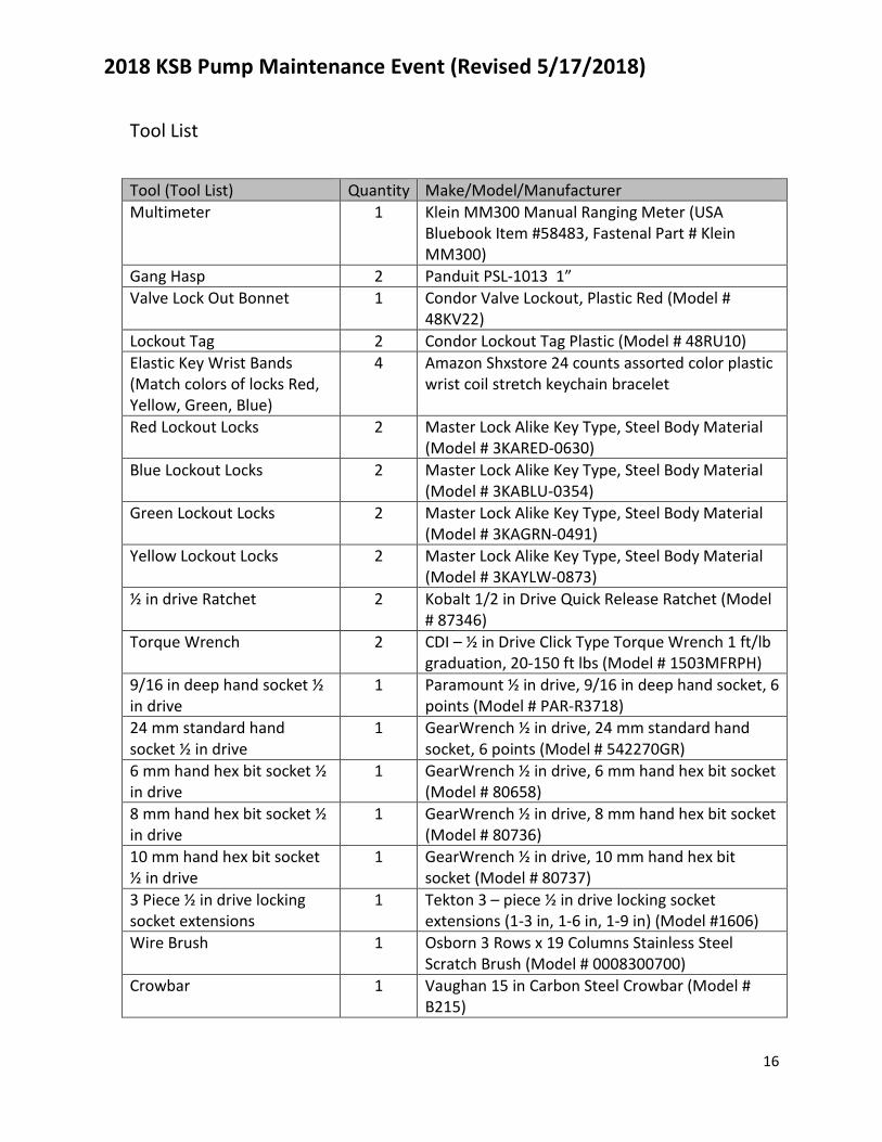
Tool List Tool (Tool List) Quantity Make/Model/Manufacturer Multimeter 1 Klein MM300 Manual Ranging Meter (USA
Bluebook Item #58483, Fastenal Part # Klein MM300)
Gang Hasp 2 Panduit PSL-1013 1” Valve Lock Out Bonnet 1 Condor Valve Lockout, Plastic Red (Model #
48KV22) Lockout Tag 2 Condor Lockout Tag Plastic (Model # 48RU10) Elastic Key Wrist Bands (Match colors of locks Red, Yellow, Green, Blue)
4 Amazon Shxstore 24 counts assorted color plastic wrist coil stretch keychain bracelet
Red Lockout Locks 2 Master Lock Alike Key Type, Steel Body Material (Model # 3KARED-0630)
Blue Lockout Locks 2 Master Lock Alike Key Type, Steel Body Material (Model # 3KABLU-0354)
Green Lockout Locks 2 Master Lock Alike Key Type, Steel Body Material (Model # 3KAGRN-0491)
Yellow Lockout Locks 2 Master Lock Alike Key Type, Steel Body Material (Model # 3KAYLW-0873)
½ in drive Ratchet 2 Kobalt 1/2 in Drive Quick Release Ratchet (Model # 87346)
Torque Wrench 2 CDI – ½ in Drive Click Type Torque Wrench 1 ft/lb graduation, 20-150 ft lbs (Model # 1503MFRPH)
9/16 in deep hand socket ½ in drive
1 Paramount ½ in drive, 9/16 in deep hand socket, 6 points (Model # PAR-R3718)
24 mm standard hand socket ½ in drive
1 GearWrench ½ in drive, 24 mm standard hand socket, 6 points (Model # 542270GR)
6 mm hand hex bit socket ½ in drive
1 GearWrench ½ in drive, 6 mm hand hex bit socket (Model # 80658)
8 mm hand hex bit socket ½ in drive
1 GearWrench ½ in drive, 8 mm hand hex bit socket (Model # 80736)
10 mm hand hex bit socket ½ in drive
1 GearWrench ½ in drive, 10 mm hand hex bit socket (Model # 80737)
3 Piece ½ in drive locking socket extensions
1 Tekton 3 – piece ½ in drive locking socket extensions (1-3 in, 1-6 in, 1-9 in) (Model #1606)
Wire Brush 1 Osborn 3 Rows x 19 Columns Stainless Steel Scratch Brush (Model # 0008300700)
Crowbar 1 Vaughan 15 in Carbon Steel Crowbar (Model # B215)
2018 KSB Pump Maintenance Event (Revised 5/17/2018)
17
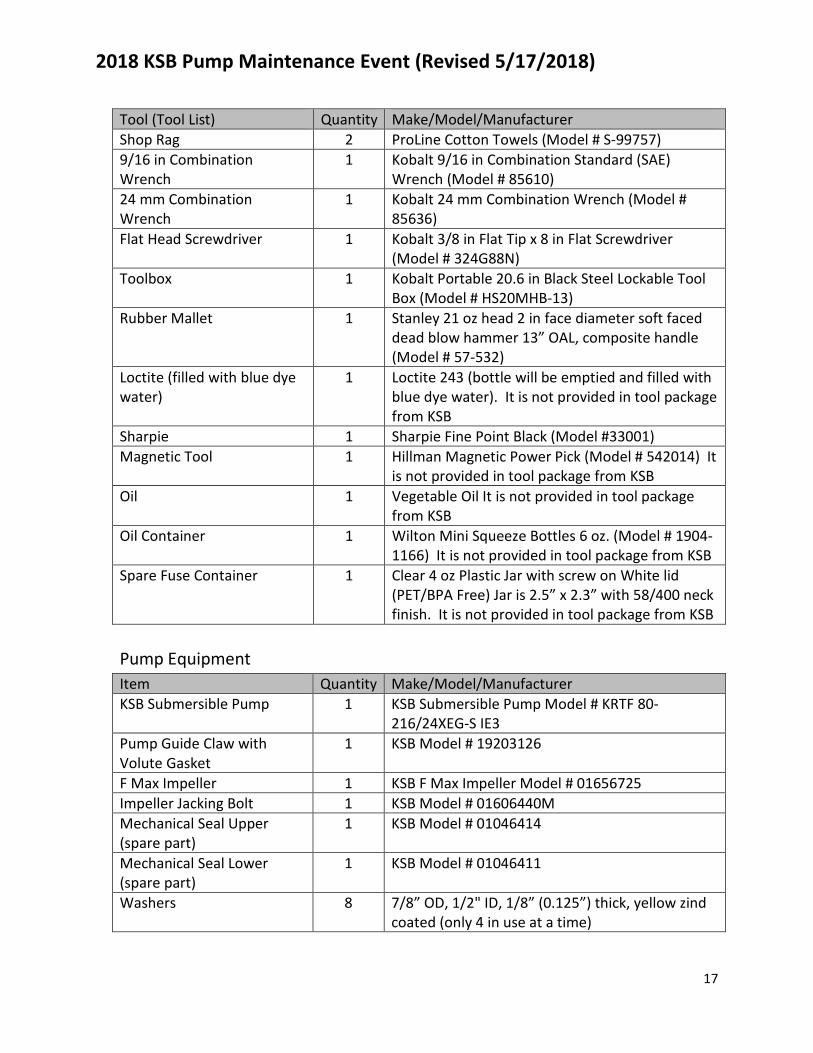
Tool (Tool List) Quantity Make/Model/Manufacturer Shop Rag 2 ProLine Cotton Towels (Model # S-99757) 9/16 in Combination Wrench
1 Kobalt 9/16 in Combination Standard (SAE) Wrench (Model # 85610)
24 mm Combination Wrench
1 Kobalt 24 mm Combination Wrench (Model # 85636)
Flat Head Screwdriver 1 Kobalt 3/8 in Flat Tip x 8 in Flat Screwdriver (Model # 324G88N)
Toolbox 1 Kobalt Portable 20.6 in Black Steel Lockable Tool Box (Model # HS20MHB-13)
Rubber Mallet 1 Stanley 21 oz head 2 in face diameter soft faced dead blow hammer 13” OAL, composite handle (Model # 57-532)
Loctite (filled with blue dye water)
1 Loctite 243 (bottle will be emptied and filled with blue dye water). It is not provided in tool package from KSB
Sharpie 1 Sharpie Fine Point Black (Model #33001) Magnetic Tool 1 Hillman Magnetic Power Pick (Model # 542014) It
is not provided in tool package from KSB Oil 1 Vegetable Oil It is not provided in tool package
from KSB Oil Container 1 Wilton Mini Squeeze Bottles 6 oz. (Model # 1904-
1166) It is not provided in tool package from KSB Spare Fuse Container 1 Clear 4 oz Plastic Jar with screw on White lid
(PET/BPA Free) Jar is 2.5” x 2.3” with 58/400 neck finish. It is not provided in tool package from KSB
Pump Equipment Item Quantity Make/Model/Manufacturer KSB Submersible Pump 1 KSB Submersible Pump Model # KRTF 80-
216/24XEG-S IE3 Pump Guide Claw with Volute Gasket
1 KSB Model # 19203126
F Max Impeller 1 KSB F Max Impeller Model # 01656725 Impeller Jacking Bolt 1 KSB Model # 01606440M Mechanical Seal Upper (spare part)
1 KSB Model # 01046414
Mechanical Seal Lower (spare part)
1 KSB Model # 01046411
Washers 8 7/8” OD, 1/2" ID, 1/8” (0.125”) thick, yellow zind coated (only 4 in use at a time)
2018 KSB Pump Maintenance Event (Revised 5/17/2018)
18
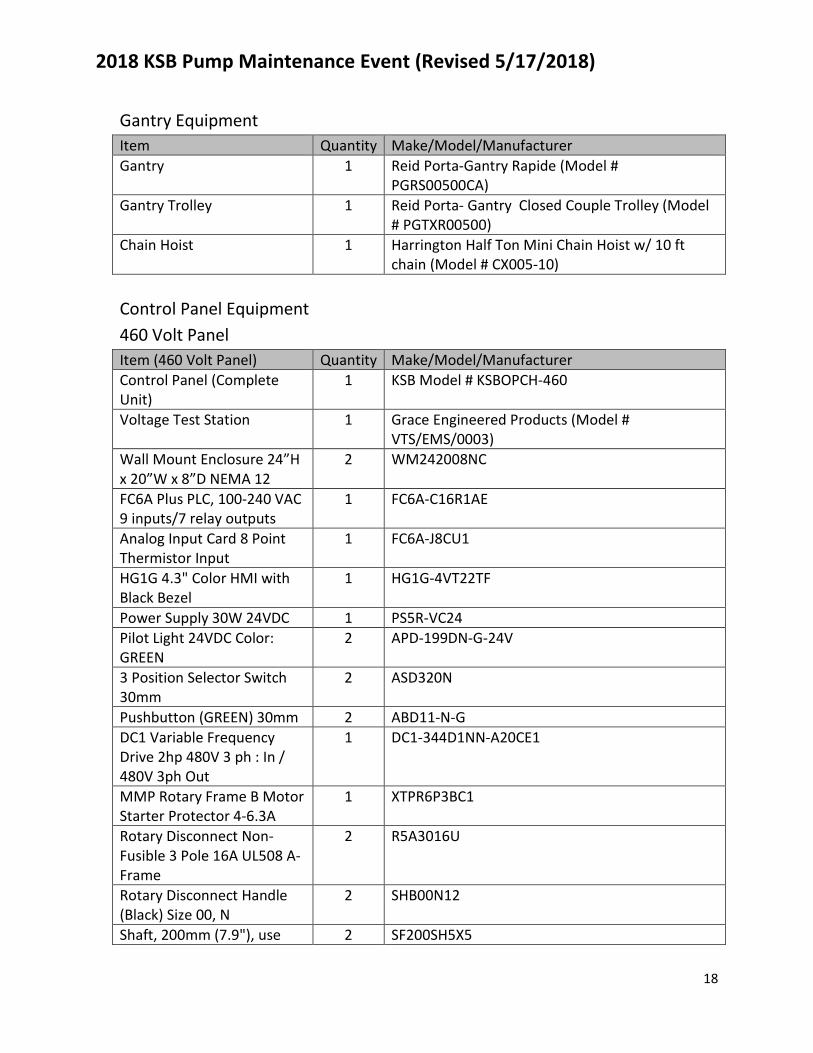
Gantry Equipment Item Quantity Make/Model/Manufacturer Gantry 1 Reid Porta-Gantry Rapide (Model #
PGRS00500CA) Gantry Trolley 1 Reid Porta- Gantry Closed Couple Trolley (Model
# PGTXR00500) Chain Hoist 1 Harrington Half Ton Mini Chain Hoist w/ 10 ft
chain (Model # CX005-10) Control Panel Equipment 460 Volt Panel Item (460 Volt Panel) Quantity Make/Model/Manufacturer Control Panel (Complete Unit)
1 KSB Model # KSBOPCH-460
Voltage Test Station 1 Grace Engineered Products (Model # VTS/EMS/0003)
Wall Mount Enclosure 24”H x 20”W x 8”D NEMA 12
2 WM242008NC
FC6A Plus PLC, 100-240 VAC 9 inputs/7 relay outputs
1 FC6A-C16R1AE
Analog Input Card 8 Point Thermistor Input
1 FC6A-J8CU1
HG1G 4.3" Color HMI with Black Bezel
1 HG1G-4VT22TF
Power Supply 30W 24VDC 1 PS5R-VC24 Pilot Light 24VDC Color: GREEN
2 APD-199DN-G-24V
3 Position Selector Switch 30mm
2 ASD320N
Pushbutton (GREEN) 30mm 2 ABD11-N-G DC1 Variable Frequency Drive 2hp 480V 3 ph : In / 480V 3ph Out
1 DC1-344D1NN-A20CE1
MMP Rotary Frame B Motor Starter Protector 4-6.3A
1 XTPR6P3BC1
Rotary Disconnect Non-Fusible 3 Pole 16A UL508 A-Frame
2 R5A3016U
Rotary Disconnect Handle (Black) Size 00, N
2 SHB00N12
Shaft, 200mm (7.9"), use 2 SF200SH5X5
2018 KSB Pump Maintenance Event (Revised 5/17/2018)
19
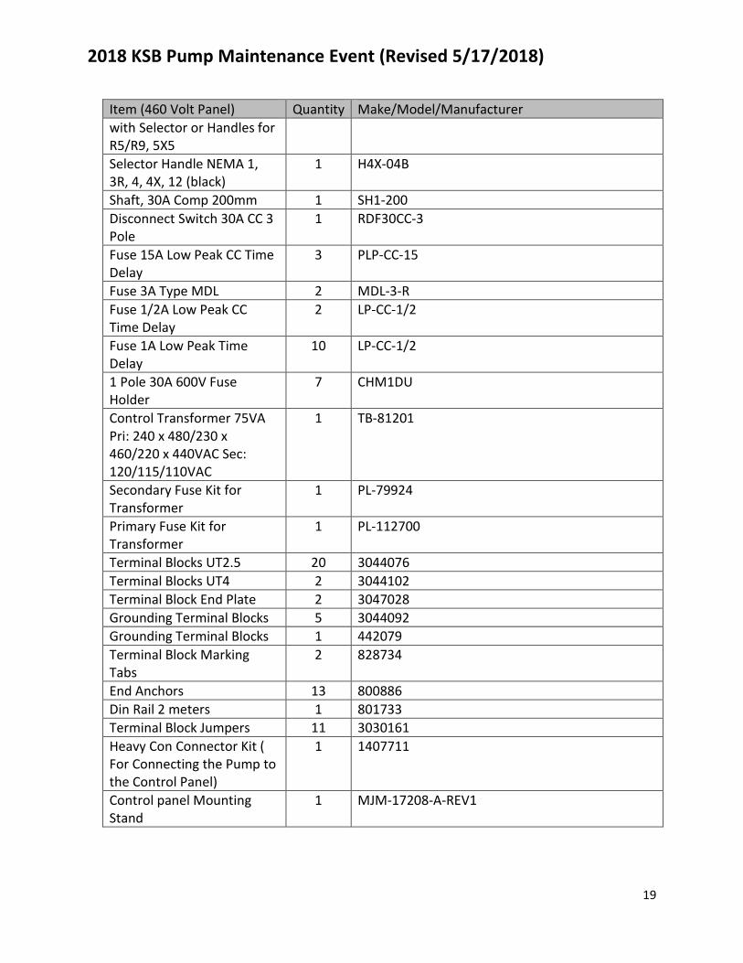
Item (460 Volt Panel) Quantity Make/Model/Manufacturer with Selector or Handles for R5/R9, 5X5 Selector Handle NEMA 1, 3R, 4, 4X, 12 (black)
1 H4X-04B
Shaft, 30A Comp 200mm 1 SH1-200 Disconnect Switch 30A CC 3 Pole
1 RDF30CC-3
Fuse 15A Low Peak CC Time Delay
3 PLP-CC-15
Fuse 3A Type MDL 2 MDL-3-R Fuse 1/2A Low Peak CC Time Delay
2 LP-CC-1/2
Fuse 1A Low Peak Time Delay
10 LP-CC-1/2
1 Pole 30A 600V Fuse Holder
7 CHM1DU
Control Transformer 75VA Pri: 240 x 480/230 x 460/220 x 440VAC Sec: 120/115/110VAC
1 TB-81201
Secondary Fuse Kit for Transformer
1 PL-79924
Primary Fuse Kit for Transformer
1 PL-112700
Terminal Blocks UT2.5 20 3044076 Terminal Blocks UT4 2 3044102 Terminal Block End Plate 2 3047028 Grounding Terminal Blocks 5 3044092 Grounding Terminal Blocks 1 442079 Terminal Block Marking Tabs
2 828734
End Anchors 13 800886 Din Rail 2 meters 1 801733 Terminal Block Jumpers 11 3030161 Heavy Con Connector Kit ( For Connecting the Pump to the Control Panel)
1 1407711
Control panel Mounting Stand
1 MJM-17208-A-REV1
2018 KSB Pump Maintenance Event (Revised 5/17/2018)
20
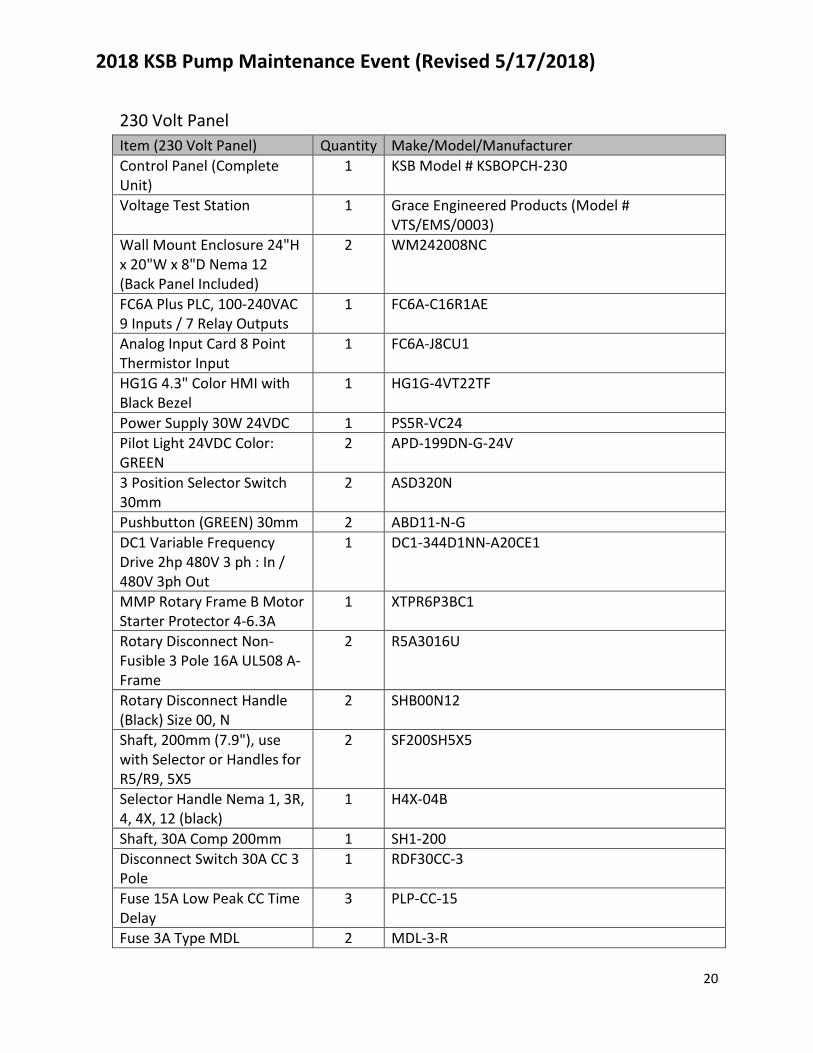
230 Volt Panel Item (230 Volt Panel) Quantity Make/Model/Manufacturer Control Panel (Complete Unit)
1 KSB Model # KSBOPCH-230
Voltage Test Station 1 Grace Engineered Products (Model # VTS/EMS/0003)
Wall Mount Enclosure 24"H x 20"W x 8"D Nema 12 (Back Panel Included)
2 WM242008NC
FC6A Plus PLC, 100-240VAC 9 Inputs / 7 Relay Outputs
1 FC6A-C16R1AE
Analog Input Card 8 Point Thermistor Input
1 FC6A-J8CU1
HG1G 4.3" Color HMI with Black Bezel
1 HG1G-4VT22TF
Power Supply 30W 24VDC 1 PS5R-VC24 Pilot Light 24VDC Color: GREEN
2 APD-199DN-G-24V
3 Position Selector Switch 30mm
2 ASD320N
Pushbutton (GREEN) 30mm 2 ABD11-N-G DC1 Variable Frequency Drive 2hp 480V 3 ph : In / 480V 3ph Out
1 DC1-344D1NN-A20CE1
MMP Rotary Frame B Motor Starter Protector 4-6.3A
1 XTPR6P3BC1
Rotary Disconnect Non-Fusible 3 Pole 16A UL508 A-Frame
2 R5A3016U
Rotary Disconnect Handle (Black) Size 00, N
2 SHB00N12
Shaft, 200mm (7.9"), use with Selector or Handles for R5/R9, 5X5
2 SF200SH5X5
Selector Handle Nema 1, 3R, 4, 4X, 12 (black)
1 H4X-04B
Shaft, 30A Comp 200mm 1 SH1-200 Disconnect Switch 30A CC 3 Pole
1 RDF30CC-3
Fuse 15A Low Peak CC Time Delay
3 PLP-CC-15
Fuse 3A Type MDL 2 MDL-3-R
2018 KSB Pump Maintenance Event (Revised 5/17/2018)
21
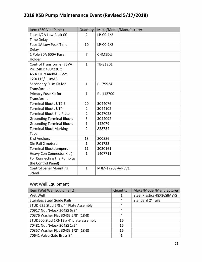
Item (230 Volt Panel) Quantity Make/Model/Manufacturer Fuse 1/2A Low Peak CC Time Delay
2 LP-CC-1/2
Fuse 1A Low Peak Time Delay
10 LP-CC-1/2
1 Pole 30A 600V Fuse Holder
7 CHM1DU
Control Transformer 75VA Pri: 240 x 480/230 x 460/220 x 440VAC Sec: 120/115/110VAC
1 TB-81201
Secondary Fuse Kit for Transformer
1 PL-79924
Primary Fuse Kit for Transformer
1 PL-112700
Terminal Blocks UT2.5 20 3044076 Terminal Blocks UT4 2 3044102 Terminal Block End Plate 2 3047028 Grounding Terminal Blocks 5 3044092 Grounding Terminal Blocks 1 442079 Terminal Block Marking Tabs
2 828734
End Anchors 13 800886 Din Rail 2 meters 1 801733 Terminal Block Jumpers 11 3030161 Heavy Con Connector Kit ( For Connecting the Pump to the Control Panel)
1 1407711
Control panel Mounting Stand
1 MJM-17208-A-REV1
Wet Well Equipment Item (Wet Well Equipment) Quantity Make/Model/Manufacturer Wet Well 1 Steel Plastics 48X36SIMSYS Stainless Steel Guide Rails 4 Standard 2” rails STUD 625 Stud 5/8 x 4” Plate Assembly 4 70917 Nut Nylock 304SS 5/8” 4 70376 Washer Flat 304SS 5/8” (18-8) 4 STUD500 Stud 1/2-13 x 4" plate assembly 16 70481 Nut Nylock 304SS 1/2" 16 70357 Washer Flat 304SS 1/2" (18-8) 16 70641 Valve Gate Brass 3" 1
2018 KSB Pump Maintenance Event (Revised 5/17/2018)
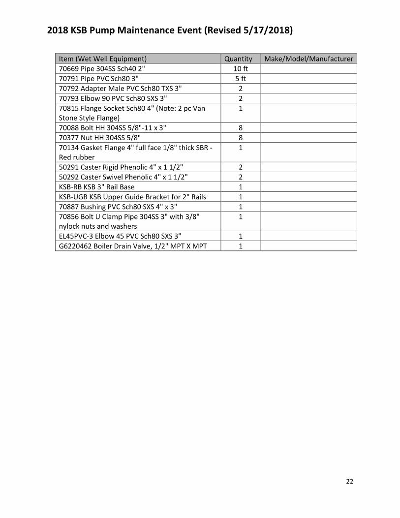
22
Item (Wet Well Equipment) Quantity Make/Model/Manufacturer 70669 Pipe 304SS Sch40 2" 10 ft 70791 Pipe PVC Sch80 3" 5 ft 70792 Adapter Male PVC Sch80 TXS 3" 2 70793 Elbow 90 PVC Sch80 SXS 3" 2 70815 Flange Socket Sch80 4" (Note: 2 pc Van Stone Style Flange)
1
70088 Bolt HH 304SS 5/8"-11 x 3" 8 70377 Nut HH 304SS 5/8" 8 70134 Gasket Flange 4" full face 1/8" thick SBR - Red rubber
1
50291 Caster Rigid Phenolic 4" x 1 1/2" 2 50292 Caster Swivel Phenolic 4" x 1 1/2" 2 KSB-RB KSB 3" Rail Base 1 KSB-UGB KSB Upper Guide Bracket for 2" Rails 1 70887 Bushing PVC Sch80 SXS 4" x 3" 1 70856 Bolt U Clamp Pipe 304SS 3" with 3/8" nylock nuts and washers
1
EL45PVC-3 Elbow 45 PVC Sch80 SXS 3" 1 G6220462 Boiler Drain Valve, 1/2" MPT X MPT 1