Embed Size (px)
Citation preview


Page 2 of 95 November 2019 Specification No. RDSO/PE/SPEC/EMU/0196–2019 (Rev.0)
Prepared by Checked by SSE/PS&EMU DSE/PS&EMU
TableofContentsABBREVIATIONS: ............................................................................................................. 5DEFINITIONS: ................................................................................................................... 7Chapter 1 : GENERAL REQUIREMENTS AND SUPPLIER’S RESPONSIBILITIES ...... 9
1.1 Introduction ............................................................................................................ 91.2 Objective ................................................................................................................ 91.3 Information to bidders ............................................................................................ 91.4 General Design Requirements: ........................................................................... 101.5 Environmental Noise Standards .......................................................................... 121.6 Signaling and Telecommunication system requirement ...................................... 121.7 TCMS/Other software requirement ...................................................................... 121.8 Supplier’s Responsibilities ................................................................................... 141.9 Purchaser’s responsibilities: ................................................................................ 151.10 Clause by Clause Compliance ........................................................................... 151.11 Approval of Design ............................................................................................ 16
Chapter 2 : OPERATING AND SERVICE CONDITIONS; DESIGN CONSTRAINTS ... 202.1 Leading Particulars: ............................................................................................. 202.2 Payload and Weight Particulars: .......................................................................... 202.3 Gauge and Moving Dimensions ........................................................................... 212.4 Track Geometry ................................................................................................... 212.5 Maximum Speed .................................................................................................. 222.6 Traction Power Supply System ............................................................................ 222.7 Overhead Equipment ........................................................................................... 232.8 Power Factor ....................................................................................................... 232.9 Fire Safety ........................................................................................................... 232.10 Ingress Protection .............................................................................................. 242.11 Climatic and Environmental Conditions ............................................................. 242.12 Signal and Telecommunication Installations: ..................................................... 252.13 Reliability, Availability, Maintainability and Safety (RAMS) ................................ 262.14 Adhesion Limits: ................................................................................................ 28
Chapter 3 : PERFORMANCE REQUIREMENTS ......................................................... 293.1 Performance Requirements ................................................................................. 293.2 Traction Performance .......................................................................................... 293.3 Brake System Performance ................................................................................. 303.4 Jerk Limit ............................................................................................................. 303.5 Ratings of equipment ........................................................................................... 313.6 Neutral Section .................................................................................................... 33

Page 3 of 95 November 2019 Specification No. RDSO/PE/SPEC/EMU/0196–2019 (Rev.0)
Prepared by Checked by SSE/PS&EMU DSE/PS&EMU
3.7 Interference to Signal and Telecommunication Installations ............................... 333.8 Train Resistance: ................................................................................................. 333.9 Equipment Layout ................................................................................................ 333.10 Minimum Clearance from Rail Level .................................................................. 33
Chapter 4 : SCOPE OF SUPPLY & TECHNICAL SPECIFICATIONS .......................... 354.1 Scope of Supply ................................................................................................... 354.2 Technical Specification for 3-Phase Propulsion System and Associated Equipment .................................................................................................................... 374.3 Traction Transformer ........................................................................................... 374.4 Lightning Arrestor ................................................................................................ 384.5 Traction Converter ............................................................................................... 384.6 Traction Motor and Drive ..................................................................................... 404.7 BOGIE DESIGN AND SUPPLY (FOR TWO PROTOTYPE RAKES) .................. 444.8 Ride Index ............................................................................................................ 474.9 Train Control and Management System (TCMS) ................................................ 474.10 Event Recorder .................................................................................................. 534.11 Voice Communication System ........................................................................... 544.12 Passenger Information System .......................................................................... 554.13 Passenger Car Surveillance System ................................................................. 564.14 Cab Recording Equipment ................................................................................. 584.15 Body Side Automatic Doors (Not in the scope of supply) .................................. 584.16 Master cum Brake Controller ............................................................................. 604.17 Driver’s Cab ....................................................................................................... 614.18 Safety Measures ................................................................................................ 644.19 Automatic Smoke/Fire Detection with Alarm System ........................................ 654.20 Speed Indicating cum recording equipment: ..................................................... 654.21 Passenger Alarm System: ................................................................................. 664.22 Control Equipment ............................................................................................. 664.23 Brake Blending .................................................................................................. 674.24 Wheel Slip/Slide Protection & Anti Skid Controls .............................................. 684.25 Parking Brake (Not in the scope of supply) ....................................................... 684.26 Load Weighing System ...................................................................................... 694.27 High Voltage Protection ..................................................................................... 704.28 Auxiliary Systems: ............................................................................................. 704.29 Battery and Battery Charger .............................................................................. 724.30 Lights: ................................................................................................................ 734.31 Head Light ......................................................................................................... 74
Page 4 of 95 November 2019 Specification No. RDSO/PE/SPEC/EMU/0196–2019 (Rev.0)
Prepared by Checked by SSE/PS&EMU DSE/PS&EMU
4.32 Tail Light ............................................................................................................ 744.33 Marker Lights ..................................................................................................... 754.34 Flasher Light ...................................................................................................... 754.35 Pneumatic System ............................................................................................. 754.36 Main Motor-Compressor Set .............................................................................. 754.37 Air – Dryer And Air Filter .................................................................................... 764.38 Filters ................................................................................................................. 774.39 Air-Conditioning System .................................................................................... 774.40 Flood Proofing of the underslung Equipment: ................................................... 814.41 Selection of Insulating Materials: ....................................................................... 814.42 Cables and Inter-vehicular Electrical couplers ................................................... 814.43 Pantograph: ....................................................................................................... 844.44 Centralized Coach Monitoring System (CCMS) ................................................ 86
Chapter 5 : TESTS & TRIALS ....................................................................................... 885.1 General ................................................................................................................ 885.2 Mechanical Tests ................................................................................................. 885.3 Electrical Tests .................................................................................................... 895.4 Complete Train: ................................................................................................... 915.5 Sequence Test: .................................................................................................... 915.6 Interference Test: ................................................................................................. 915.7 Pacemaker Interference Test: ............................................................................. 915.8 Test on Combined Test Bed: ............................................................................... 915.9 Vibration and Shock Values: ................................................................................ 925.10 Service Tests ..................................................................................................... 925.11 Performance Test (On Prototype Rakes) ......................................................... 925.12 Energy Consumption ......................................................................................... 935.13 Installation of Equipment at Purchaser premises: ............................................. 935.14 Commissioning of Trains at Purchaser’s works and Maintenance depot: ........ 945.15 Test for Air Spring Deflation Detection System: ................................................ 94
LIST OF ANNEXURES .................................................................................................... 95

Page 5 of 95 November 2019 Specification No. RDSO/PE/SPEC/EMU/0196–2019 (Rev.0)
Prepared by Checked by SSE/PS&EMU DSE/PS&EMU
ABBREVIATIONS:
Abbreviation Full Name
AC Alternating Current
ASIC Application Specific Integrated Circuit
ASHRAE American Society of Heating, Refrigeration and Air-conditioning Engineers
ATP Automatic Train Protection
BC Brake Cylinder
BG Broad Gauge
BP Brake Pipe
BS British Standards
CR Central Railway
DB & WB Dry Bulb and Wet Bulb
DC Direct Current
EER Energy Efficiency Ratio
EMC Electro-magnetic Compatibility
EMI Electro-magnetic Interference
EN Euro Norm (European Standard)
EMU Electrical Multiple Unit
EP Electro Pneumatic
FEM Finite Element Method
GPS Global Positioning System
GSM Global System for Mobile
GSM-R Global System for Mobile – Railways
HT High Tension voltage as defined in Indian Electricity Rules
IC Integrated Circuit
ICF Integral Coach Factory
IEC International Electro technical Commission
IEEE Institution of Electrical and Electronic Engineers
IGBT Insulated Gate Bipolar Transistor
IPR Intellectual Property Right
Page 6 of 95 November 2019 Specification No. RDSO/PE/SPEC/EMU/0196–2019 (Rev.0)
Prepared by Checked by SSE/PS&EMU DSE/PS&EMU
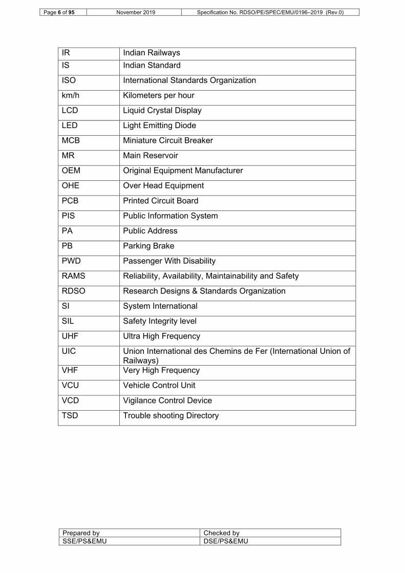
IR Indian Railways IS Indian Standard
ISO International Standards Organization
km/h Kilometers per hour
LCD Liquid Crystal Display
LED Light Emitting Diode
MCB Miniature Circuit Breaker
MR Main Reservoir
OEM Original Equipment Manufacturer
OHE Over Head Equipment
PCB Printed Circuit Board
PIS Public Information System
PA Public Address
PB Parking Brake
PWD Passenger With Disability
RAMS Reliability, Availability, Maintainability and Safety
RDSO Research Designs & Standards Organization
SI System International
SIL Safety Integrity level
UHF Ultra High Frequency
UIC Union International des Chemins de Fer (International Union of Railways)
VHF Very High Frequency
VCU Vehicle Control Unit
VCD Vigilance Control Device
TSD Trouble shooting Directory

Page 7 of 95 November 2019 Specification No. RDSO/PE/SPEC/EMU/0196–2019 (Rev.0)
Prepared by Checked by SSE/PS&EMU DSE/PS&EMU
DEFINITIONS:
Term Definition
BG shall mean 1676 mm broad gauge used in IR
Basic Unit Shall mean a composite unit of four Cars comprising two Motorized Car and two Trailer Car
Bidder ‘Bidder’ means the firm or Company or Joint Venture or Consortium who submits offer for supply of the goods and services against the tender.
End Basic Unit Basic unit with Driving Car
Middle Basic Unit Basic Unit without Driving Car but with shunting panel
Car shall mean a passenger carrying Car, built in conformity with the provisions of this Specification
Driver shall mean the person in the Driving Cab who is in control of the operation of the Train
Driving Cab shall mean a cabin, segregated from the passenger area, and situated at the end of a Car of Train, and includes the equipment and Sub-systems forming part thereof
Driving Car shall mean Car with Driving Cab
Train shall mean Train comprising multiple Basic Units
16/20 Car Train shall mean a Train comprising 4/5 (four/five) Basic Units of 4-Car each
IP or Ingress Protection
shall mean the degree of protection provided by enclosures in accordance with IEC 60529
IR Field Unit EMU maintenance shed/workshop of Indian Railways
L-10 shall mean life of bearing in accordance with ISO 281
Motorized Car (MC) shall mean a Car fitted with traction motor on all axles
NDTC shall mean Non Driving Trailer Coach
Human Machine Interface (HMI)
shall mean driver's display and the interface between the system or equipment & the human
Propulsion Equipment
shall mean and include traction transformer, traction motor, traction converters, auxiliary converters and electronics (hardware and software for propulsion system)
Pantograph Car Car fitted with one pantograph
Purchaser ‘Purchaser’ means any organization of Indian Railway
Rail Level the plane which passes through the top of the cross-sectional center line of both running rails
RDSO shall mean the Research Designs and Standards
Page 8 of 95 November 2019 Specification No. RDSO/PE/SPEC/EMU/0196–2019 (Rev.0)
Prepared by Checked by SSE/PS&EMU DSE/PS&EMU
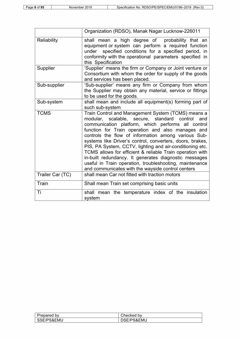
Organization (RDSO), Manak Nagar Lucknow-226011
Reliability shall mean a high degree of probability that an equipment or system can perform a required function under specified conditions for a specified period, in conformity with the operational parameters specified in this Specification
Supplier ‘Supplier’ means the firm or Company or Joint venture or Consortium with whom the order for supply of the goods and services has been placed.
Sub-supplier ‘Sub-supplier’ means any firm or Company from whom the Supplier may obtain any material, service or fittings to be used for the goods.
Sub-system shall mean and include all equipment(s) forming part of such sub-system
TCMS Train Control and Management System (TCMS) means a modular, scalable, secure, standard control and communication platform, which performs all control function for Train operation and also manages and controls the flow of information among various Sub-systems like Driver’s control, converters, doors, brakes, PIS, PA System, CCTV, lighting and air-conditioning etc. TCMS allows for efficient & reliable Train operation with in-built redundancy. It generates diagnostic messages useful in Train operation, troubleshooting, maintenance and communicates with the wayside control centers
Trailer Car (TC) shall mean Car not fitted with traction motors
Train Shall mean Train set comprising basic units
Ti shall mean the temperature index of the insulation system
Page 9 of 95 November 2019 Specification No. RDSO/PE/SPEC/EMU/0196–2019 (Rev.0)
Prepared by Checked by SSE/PS&EMU DSE/PS&EMU
Chapter 1 : GENERAL REQUIREMENTS AND SUPPLIER’S RESPONSIBILITIES
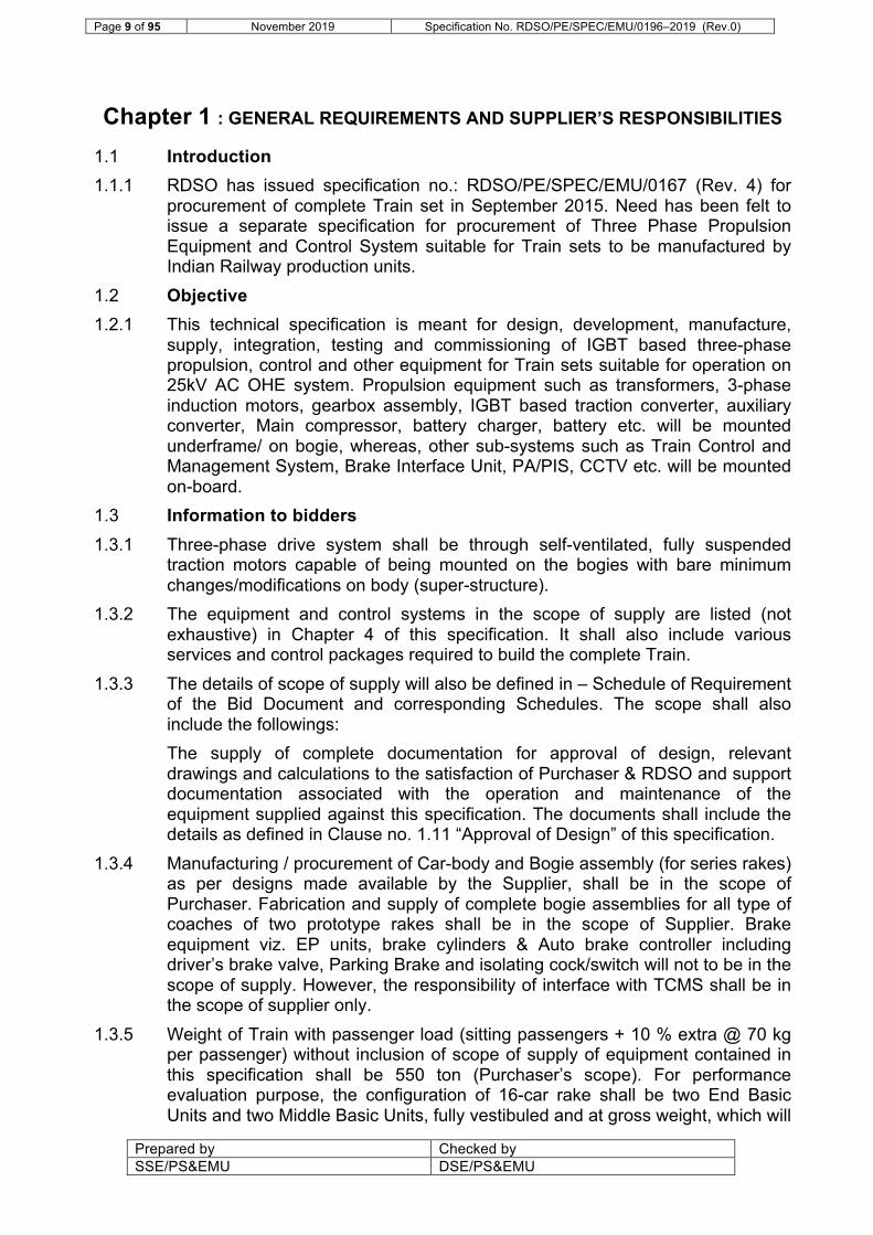
1.1 Introduction 1.1.1 RDSO has issued specification no.: RDSO/PE/SPEC/EMU/0167 (Rev. 4) for
procurement of complete Train set in September 2015. Need has been felt to issue a separate specification for procurement of Three Phase Propulsion Equipment and Control System suitable for Train sets to be manufactured by Indian Railway production units.
1.2 Objective 1.2.1 This technical specification is meant for design, development, manufacture,
supply, integration, testing and commissioning of IGBT based three-phase propulsion, control and other equipment for Train sets suitable for operation on 25kV AC OHE system. Propulsion equipment such as transformers, 3-phase induction motors, gearbox assembly, IGBT based traction converter, auxiliary converter, Main compressor, battery charger, battery etc. will be mounted underframe/ on bogie, whereas, other sub-systems such as Train Control and Management System, Brake Interface Unit, PA/PIS, CCTV etc. will be mounted on-board.
1.3 Information to bidders 1.3.1 Three-phase drive system shall be through self-ventilated, fully suspended
traction motors capable of being mounted on the bogies with bare minimum changes/modifications on body (super-structure).
1.3.2 The equipment and control systems in the scope of supply are listed (not exhaustive) in Chapter 4 of this specification. It shall also include various services and control packages required to build the complete Train.
1.3.3 The details of scope of supply will also be defined in – Schedule of Requirement of the Bid Document and corresponding Schedules. The scope shall also include the followings: The supply of complete documentation for approval of design, relevant drawings and calculations to the satisfaction of Purchaser & RDSO and support documentation associated with the operation and maintenance of the equipment supplied against this specification. The documents shall include the details as defined in Clause no. 1.11 “Approval of Design” of this specification.
1.3.4 Manufacturing / procurement of Car-body and Bogie assembly (for series rakes) as per designs made available by the Supplier, shall be in the scope of Purchaser. Fabrication and supply of complete bogie assemblies for all type of coaches of two prototype rakes shall be in the scope of Supplier. Brake equipment viz. EP units, brake cylinders & Auto brake controller including driver’s brake valve, Parking Brake and isolating cock/switch will not to be in the scope of supply. However, the responsibility of interface with TCMS shall be in the scope of supplier only.
1.3.5 Weight of Train with passenger load (sitting passengers + 10 % extra @ 70 kg per passenger) without inclusion of scope of supply of equipment contained in this specification shall be 550 ton (Purchaser’s scope). For performance evaluation purpose, the configuration of 16-car rake shall be two End Basic Units and two Middle Basic Units, fully vestibuled and at gross weight, which will

Page 10 of 95 November 2019 Specification No. RDSO/PE/SPEC/EMU/0196–2019 (Rev.0)
Prepared by Checked by SSE/PS&EMU DSE/PS&EMU
be equivalent to 550 ton and weight of supplied equipment under scope of supply of this specification (all items mentioned in clause 4.1 to be considered). Each basic unit shall consist of four Cars i.e. two motorized Car (MC) and two trailer Cars (TC).
1.3.6 It should however be possible to increase the train length up to six basic units i.e. twenty-four coaches by adding middle basic units and all systems including TCMS should be capable to support this.
1.3.7 In developing the detailed design, the supplier shall acquaint himself and take note of the track and environmental operating conditions prevailing on IR specially during heavy monsoon, track flooding conditions, saline, humid and dusty atmosphere etc.
1.3.8 Leading Car of both the End Basic Units shall be provided with driving cab having driver's console housing the safety related equipment, instruments and combined master cum brake controller etc.
1.3.9 Each basic unit shall be provided with one pantograph along with associated high voltage equipment.
1.3.10 Each Middle Basic Unit shall be provided with a detachable handheld shunting unit panel, which shall facilitate movement of a single middle basic unit for the shunting purpose if one of the end basic unit is connected. With this unit, it shall be possible to start the basic unit from de-energized condition, move the basic unit with a limited speed and de-energize it again. Shunting operation of End Basic Units, shall be accomplished through the regular driver’s desk.
1.3.11 Same type of Cars for the same supplier shall be interchangeable from one basic unit/rake to another basic unit/rake formation.
1.3.12 The configuration of Train 18 manufactured by IR is as under (for reference): DTC-MC-TC-MC2-NDTC-MC-TC-MC2-NDTC-MC-TC-MC2-MC3-TC-MC-DTC
1.3.13 The Govt. of India policy on ‘Make in India’ shall apply. 1.4 General Design Requirements: 1.4.1 Three-phase propulsion equipment shall be suitable for mounting on the
underframe. Fitment of various equipment/ systems on underslung/ bogie will be so decided that the weight is properly distributed with least possible weight unbalancing during tare condition. No equipment or cubicles shall be generally permitted within the car body except at the ends of the coach. The load on axle for any car shall not exceed the maximum permissible axle load under any condition.
1.4.2 The stock fitted with the supplied equipment shall meet the operating, service conditions and performance requirements of this specification and shall be suitable for operating conditions on IR.
1.4.3 All equipment shall be vandal proof and incorporate necessary anti-pilferage features without compromising aesthetics / maintainability.
1.4.4 Notwithstanding the contents of this specification, the Supplier shall ensure that the equipment supplied by them is complete in all respect so as to achieve the efficient operation & optimum performance of the Train set.

Page 11 of 95 November 2019 Specification No. RDSO/PE/SPEC/EMU/0196–2019 (Rev.0)
Prepared by Checked by SSE/PS&EMU DSE/PS&EMU
1.4.5 The equipment design shall incorporate all essential features necessary to yield high traffic use, low maintenance requirements, easy maintainability, high regeneration, high efficiency, light in weight, user & environment friendly and high reliability in train operation. The design shall also facilitate easy erection, inspection, maintenance and replacement of the sub-units/ assemblies of all the equipment. The total weight of the items under scope of supply of this specification (all items mentioned in clause 4.1 to be considered) shall not exceed 410 ton.
1.4.6 The entire equipment shall be designed to ensure satisfactory and safe operation under the running conditions mentioned in this specification duly taking care of sudden variations in load, voltage etc. under abnormal working conditions due to faulty operation, short circuits & earth faults etc.
1.4.7 Airflow inlet/ arrangement for forced cooled equipment shall be designed in such a way that cloth, polythene, papers etc., which may get sucked, either do not block the airflow or get removed during halts. Moreover, filter should be easily cleanable.
1.4.8 All working parts of the control and auxiliary circuit specifically electronics and PCBs, shall be suitably covered to keep them free from moisture, mould growth and dust. The protection level shall be furnished by the Supplier during design approval.
1.4.9 All the electrical equipment shall comply with the latest edition of governing IEC specifications unless otherwise specified. The temperature rise shall be measured according to the procedure stipulated by IEC and shall comply with the limits specified and the ambient conditions defined in the Specification. Specified temperature rise of equipment shall be calculated after taking into account at least 25% choking of air filters and radiator fins etc.
1.4.10 All equipment shall be adequately earthed, insulated, screened or enclosed. They shall be provided with essential interlocks & keys as may be adequate to ensure the protection of the equipment and the safety of those concerned with its operation and maintenance.
1.4.11 Supplier shall to the extent feasible employ the currently available lubricants/cooling oils in India. Full lubrication scheme and schedule for the equipment shall be submitted. If use of imported lubricants or cooling oil is inevitable, supplier shall furnish details of equivalent Indian lubricants/oil.
1.4.12 Proven Equipment: The design of the equipment shall be based on sound, proven and reliable engineering practices. The equipment used in different sub systems shall be of proven technology and design.
1.4.13 Supplier shall submit list of equipment and facilities required for maintenance and overhaul of equipment offered.
1.4.14 RDSO shall examine the design document, test specification and witness the prototype tests/results. In addition, technical details of modification resulting in any change in the design and layout of the train/ basic unit shall also be examined.
1.4.15 Supplier shall submit the basic details of their system design, weight particulars and its disposition, covering all major items viz. transformer, traction converter, auxiliary converter, traction motor, auxiliary machines, software specification,

Page 12 of 95 November 2019 Specification No. RDSO/PE/SPEC/EMU/0196–2019 (Rev.0)
Prepared by Checked by SSE/PS&EMU DSE/PS&EMU
control electronics, compressor, TCMS communication protocols, display systems, air-conditioning, PA/PIS, CCTV, system expandability and any other aspect/equipment which is within the scope of supply of the Supplier. Supplier shall refer Annexure I while submitting such details.
1.5 Environmental Noise Standards 1.5.1 General
The noise levels emitted from the Train with supplied equipment shall be as low as possible and the equipment shall be designed to prevent drumming, rattles or vibrations throughout their Design Life. All noise levels specified below are in decibels referred to 20 micro Pascal as measured with “A” weighting network of standard Type 1 sound level meter with time weighting F. During the measurements, end wall doors between Cars, body side doors, intermediate doors and windows of the vehicle shall be kept closed, unless their influence upon the sound level inside the vehicle is to be investigated.
1.5.2 Limits of Interior Noise The noise level in passenger area of the Car shall not exceed 65 dB(A) when stationary and shall not exceed 70 dB(A) at maximum service speed with all auxiliary equipment operating at its greatest noise output. The noise level shall be measured in the Car along the center line between 1200 mm and 1600 mm above the floor and at a distance not less than 600 mm from the end of the Car. The measurement shall be done as per ISO 3381.
1.5.3 Limits of Stationary Noise The limiting value for noise emission of the Train with supplied equipment shall be 68 dB(A) at a distance of 7.5 m from the center line of the track, 1.2 m and 3.5 m above the upper surface of the rails. The measurement shall be done in accordance with the standard EN ISO 3095.
1.5.4 Limits of Starting Noise The limiting value for noise emission of the Train with supplied equipment shall be 82 dB(A) at a distance of 7.5 m from the center line of the track, 1.2 m and 3.5 m above the upper surface of the rails. The measurement shall be done in accordance with the standard EN ISO 3095.
1.6 Signaling and Telecommunication system requirement 1.6.1 The Supplier shall ensure the full interface of control system with Train
Protection and Warning System (TPWS), Automatic Train Protection (ATP) or Communications-Based Train Control (CBTC), which IR may provide in future. Supplier shall therefore make the details available on the interface signal/protocol of TCMS available in its system for TPWS/ATP/CBTC interface to the purchaser.
1.7 TCMS/Other software requirement 1.7.1 Software shall be written in a structured manner and fully documented during
all stages of its design and development. This shall meet the requirements of EN 50126-2: The specification and Demonstration of Reliability, Availability, Maintainability and Safety (RAMS) - Part 2, EN 50128 : Railway Applications : Software for Railway Control and Protection Systems, and EN 50129: Safety-related Electronic Railway Control and Protection Systems.

Page 13 of 95 November 2019 Specification No. RDSO/PE/SPEC/EMU/0196–2019 (Rev.0)
Prepared by Checked by SSE/PS&EMU DSE/PS&EMU
1.7.2 Logic of the Software of various sub-systems shall be approved by RDSO in consultation with user Railways at the design approval stage. The Supplier shall submit the values of parameters, list of fault messages, their environmental data, hierarchy of fault display, fault categorization, trouble shooting of each fault by way of graphical representation on HMI etc. for the approval. Changes in parameters shall be demonstrated with their effect on the results.
1.7.3 The Supplier shall submit software logic with detailed explanation along with complete software packages used in TCMS and Converter control before commissioning of the prototype rake. Parametric changes shall be possible in the software in order to meet the future requirements viz. change in acceleration & deceleration, bogie & coach suspension, train configurations, OHE voltage, frequency etc. within permissible limits. While listing out the values of various parameters, the Supplier must provide a range within which any change can be made without jeopardizing the functionality of the system. Supplier shall submit one copy of the licensed software to the user Railway before uploading the same on the train.
1.7.4 Software shall be fine tuned through simulations & real life working conditions based on the extensive trials, associating user Railways before putting the rake in commercial services. As it requires, instrumentation and expertise of Software Design Professionals, software expert(s) of Supplier shall be based at the work place along with commissioning engineers so that all software related issues are expeditiously resolved before putting the rake into commercial service.
1.7.5 Quality and efficacy of trouble shooting manual, software tools and software documentation shall be validated during extensive field trials. Final version of these documents shall include the changes required based on the service trials, commercial service operation, experience of operating Railways and shall be submitted after the expiry of the warranty period of the prototype rakes.
1.7.6 All the changes, thereafter, in software shall be approved by RDSO in consultation with user Railways before actual implementation and the Supplier must give software release, which shall include brief description of the problem, earlier as well as modified logic, explanation, parametric changes etc. to the satisfaction of RDSO.
1.7.7 The Supplier shall submit Software Quality Plan for review before work commences on software design. The software quality plan shall clearly state the controls and practices used in the software life cycle from specification through to in-service operation.
1.7.8 Internal independent review, verification & testing, using real & synthetic data, shall be performed at the software module and system level. RDSO/user Railway may audit the Supplier against the Software Quality Plan at any stage during the Contract. The Supplier shall ensure that all software is fully de-bugged prior to the final review by RDSO/user Railway.
1.7.9 Sufficient software documentation shall be provided to give the full understanding of the software function, logics, parameters and operation. Documentation shall be complete, clear and concise, and include all modifications up to the final acceptance. Documentation shall clearly explain the software logics, associated parameters, include software block diagram

Page 14 of 95 November 2019 Specification No. RDSO/PE/SPEC/EMU/0196–2019 (Rev.0)
Prepared by Checked by SSE/PS&EMU DSE/PS&EMU
showing signal flow, logic and hardware interfaces etc. A top level flow diagram and description of detailed operation shall be provided.
1.7.10 FIRE PREVENTION MEASURES (i) Each equipment/ system shall be designed to minimize the risk of
any fire. (ii) Materials used in the manufacture of equipment shall be selected to
reduce the heat load, rate of heat release, propensity to ignite, rate of flame spread, smoke emission and toxicity of combustion gases.
(iii) The Supplier shall comply with standard EN 45545 HL-2/ HL-3 for all equipment under scope of supply for sitting/ sleeper services respectively.
1.8 Supplier’s Responsibilities The Supplier’s responsibilities will extend to the following:
1.8.1 Supplier shall design the mounting arrangements of different equipment/ sub-assembly in scope of this specification, in consultation with Purchaser suitable for Cars to be manufactured. The accessories and hardware for mounting the equipment, safety links for underslung equipment shall be in the scope of supply.
1.8.2 Installation of supplied equipment and control system is generally not in the scope of Supplier. The Supplier shall therefore make available the detailed instructions, drawings and relevant specifications for proper installation of the equipment and system in coaches to Purchaser and RDSO or any other agency nominated by Purchaser. Supplier shall depute engineers to Purchaser or any other manufacturer’s premises authorised by Purchaser for supervision of installation of the equipment on coaches of all the rakes.
1.8.3 Commissioning of supplied equipment and control system on all Train set rakes at Purchaser’s field units and tests & trials of prototype rakes at IR field units shall be carried out by the trained engineers of Supplier along with support staff to ensure that the each interface & equipment assembly perform its intended function.
1.8.4 Pre-commissioning of prototype and all the series rakes at Production units (Purchaser’s site), shall be done by trained engineers of suppliers along with support staff. The Supplier shall be responsible for commissioning & testing on respective Zonal Railways (for all rakes) and service trials of the equipment on prototype rakes. They shall depute team of engineers to Zonal Railways for the same. The commissioning teams of PUs/ Zonal Railways shall also be associated during pre-commissioning/ commissioning.
1.8.5 The Supplier shall arrange required instrumentation and carry out detailed tests and service trials jointly with RDSO, Zonal Railway & Purchaser/ Railway maintenance shed/workshop/any other manufacturer nominated by IR as per Chapter 5 of this Specification.
1.8.6 The Supplier shall be entirely responsible for the execution of the Contract in accordance with the requirements of this Specification.
1.8.7 The Supplier shall submit a technical plan, giving details of overall system design, Project organization chart, project schedule clearly defining the start &

Page 15 of 95 November 2019 Specification No. RDSO/PE/SPEC/EMU/0196–2019 (Rev.0)
Prepared by Checked by SSE/PS&EMU DSE/PS&EMU
completion of activity through PERT/Bar chart and schedule of submission of design documents/drawings to the Purchaser and RDSO as specified in the delivery schedule of the contract.
1.8.8 The software required for trouble-shooting and software tools for maintenance of equipment shall be supplied to the sheds and workshops before start of commissioning to the satisfaction of commissioning team of IR. Supplier shall demonstrate the procedure of trouble shooting through the software tools.
1.8.9 Complete information on equipment testing, commissioning at site/on train, their interface and complete system testing shall be provided.
1.8.10 Supply of drawings, operating manuals, maintenance manuals, trouble-shooting manuals and software manuals of the supplied equipment and systems shall be ensured.
1.8.11 In addition to the equipment and services specified in this Specification, the Supplier shall supply special handling tackle, special tools and appliances which may be necessary for the installation, testing and commissioning of the supplied equipment on the newly manufactured rakes, even though such material or work may not be specifically mentioned in this Specification/ purchase order. The same can however be taken back after successful installation, commissioning and completion of testing activities on all rakes in all respect.
1.8.12 Save otherwise exempted under this specification, two prototype rakes, fitted with the supplied equipment after the successful completion of all tests and trials and RDSO clearance shall undergo service trials for six months or one lakh km whichever is earlier. Clearance for supply of equipment for series rakes shall be given by RDSO after successful service trials for six months or one lakh km as stated above of any of the prototype rakes. The supply of equipment for the “work in progress” for the period of service trials can commence as agreed by the supplier and purchaser so that the continuity of the production is not affected. During the prototype tests/service trials, if any problem arise or feedback is obtained, which warrants a re-check of the design/manufacture/quality of the equipment and components, action will be taken as may be necessary by the Supplier to carry out the required investigations and to incorporate the modification considered most appropriate to reach compliance with the specification without any extra costs to the Purchaser and in a manner approved by the RDSO on equipment/components already supplied as well as those to be supplied later.
1.8.13 Before carrying out any modification, as found necessary on the basis of tests and trials, the drawings and execution plan shall be got approved from the RDSO.
1.9 Purchaser’s responsibilities: 1.9.1 Provision of space in their premises to Supplier for facilitating the work as per
prevalent practices. 1.10 Clause by Clause Compliance
The Bidder shall furnish clause-by-clause compliance on this technical specification. Supplier shall submit the detailed information desired vide various clauses of the specification at the time of design stage giving clause by clause compliance and giving cross reference of the relevant section of the design

Page 16 of 95 November 2019 Specification No. RDSO/PE/SPEC/EMU/0196–2019 (Rev.0)
Prepared by Checked by SSE/PS&EMU DSE/PS&EMU
document. The comments like ‘noted’ against the respective clauses shall be considered as ‘not complied’ for the specific clause. Therefore, the Bidder shall clearly indicate the compliance or otherwise by writing ‘Complied’ or ‘Not Complied’. Clause by clause compliance to the specification shall only be considered for evaluation of offers. Compliance against any clause means compliance of all of its sub-clauses. Other details given by Bidder shall not be given cognizance and shall not amount to the acceptance of the design/equipment/scheme. In case of any discrepancy, clause-by-clause compliance to the specification shall only be considered. It shall be the responsibility of the Supplier to meet the specification as per the clause-by-clause compliance.
1.11 Approval of Design 1.11.1 The design shall be developed based on the requirements given in this
specification and sound engineering practices with specific consideration to the specified passenger loading condition, route conditions and environmental conditions. The basic design for system and major equipment shall be submitted by the Supplier with required technical data and calculations to RDSO for approval. Any calculation which is evaluated on the basis of software simulations shall be supported with sample calculations.
1.11.2 After the contract is signed, the Supplier shall furnish to RDSO and the purchaser, the detailed schedule programme for submission of design documents for approval, which shall be suitably staggered, to enable RDSO to plan for expeditious clearance.
1.11.3 The Supplier shall depute his technical experts to RDSO for design discussions and finalisation of documents. The Supplier shall deliver all necessary data, designs, calculations, drawings and specifications in English language for examination and shall provide explanation and clarification of the drawings for which approval is sought. The submission of design document for any equipment for approval by the Supplier without the complete information as per the contract specification shall not be considered as submission of document. The Supplier shall furnish complete set of applicable standards/specifications as mentioned in the approved drawings & documents and shall also submit the list of equivalent Indian Standards, wherever applicable.
1.11.4 Supplier shall submit technical details as per Annexure I along with technical specification, functional specifications, block diagrams, schematic drawings, ratings, load calculation, simulation results for train performance, circuits, wiring diagrams, design of converter, inverter and other power & control equipment, weight balancing calculations, train control networking, protocols used and the software details for carrying out modifications as permissible. The loading of electronic equipment/components calculated under the ambient conditions as specified, air-conditioning design and component rating etc. shall be got approved. While the aspects covered, as above, are not exhaustive, the Supplier shall supply/furnish complete technical details with respect to their system and equipment design and to the satisfaction of RDSO at the time of design approval.
1.11.5 The design shall be developed in SI units.
Page 17 of 95 November 2019 Specification No. RDSO/PE/SPEC/EMU/0196–2019 (Rev.0)
Prepared by Checked by SSE/PS&EMU DSE/PS&EMU
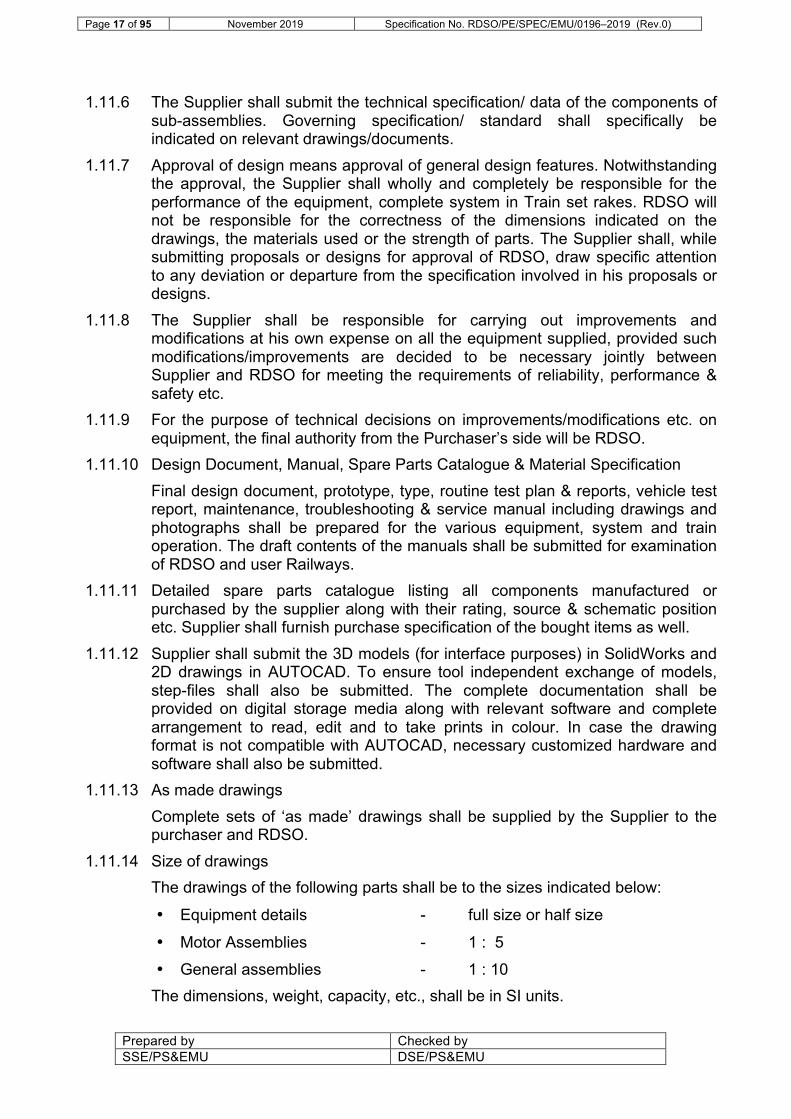
1.11.6 The Supplier shall submit the technical specification/ data of the components of sub-assemblies. Governing specification/ standard shall specifically be indicated on relevant drawings/documents.
1.11.7 Approval of design means approval of general design features. Notwithstanding the approval, the Supplier shall wholly and completely be responsible for the performance of the equipment, complete system in Train set rakes. RDSO will not be responsible for the correctness of the dimensions indicated on the drawings, the materials used or the strength of parts. The Supplier shall, while submitting proposals or designs for approval of RDSO, draw specific attention to any deviation or departure from the specification involved in his proposals or designs.
1.11.8 The Supplier shall be responsible for carrying out improvements and modifications at his own expense on all the equipment supplied, provided such modifications/improvements are decided to be necessary jointly between Supplier and RDSO for meeting the requirements of reliability, performance & safety etc.
1.11.9 For the purpose of technical decisions on improvements/modifications etc. on equipment, the final authority from the Purchaser’s side will be RDSO.
1.11.10 Design Document, Manual, Spare Parts Catalogue & Material Specification Final design document, prototype, type, routine test plan & reports, vehicle test report, maintenance, troubleshooting & service manual including drawings and photographs shall be prepared for the various equipment, system and train operation. The draft contents of the manuals shall be submitted for examination of RDSO and user Railways.
1.11.11 Detailed spare parts catalogue listing all components manufactured or purchased by the supplier along with their rating, source & schematic position etc. Supplier shall furnish purchase specification of the bought items as well.
1.11.12 Supplier shall submit the 3D models (for interface purposes) in SolidWorks and 2D drawings in AUTOCAD. To ensure tool independent exchange of models, step-files shall also be submitted. The complete documentation shall be provided on digital storage media along with relevant software and complete arrangement to read, edit and to take prints in colour. In case the drawing format is not compatible with AUTOCAD, necessary customized hardware and software shall also be submitted.
1.11.13 As made drawings Complete sets of ‘as made’ drawings shall be supplied by the Supplier to the purchaser and RDSO.
1.11.14 Size of drawings The drawings of the following parts shall be to the sizes indicated below:
• Equipment details - full size or half size
• Motor Assemblies - 1 : 5
• General assemblies - 1 : 10 The dimensions, weight, capacity, etc., shall be in SI units.

Page 18 of 95 November 2019 Specification No. RDSO/PE/SPEC/EMU/0196–2019 (Rev.0)
Prepared by Checked by SSE/PS&EMU DSE/PS&EMU
1.11.15 Method of filing of drawings To facilitate filing of drawings, it is essential that each drawing submitted for approval is marked so that it can be identified. The supplier is, therefore, required to ensure that all prints are marked legibly at the right hand bottom corner. The following information is required in respect of each drawing: (i) Supplier’s drawing number. (ii) Supplier’s name and date of submission. (iii) Contract no. given by the purchaser. (iv) Description of drawings. (v) Relevant Specifications
1.11.16 Photographs While the prototype equipment is under manufacture/ assembly, photographs of the various assemblies and sub-assemblies in various stages of production shall be taken. Photograph size shall not be less than 305 x 203 mm. Photographs shall be submitted in the form of books suitably bound with a cover of superior quality & durable material with the title block printed on the cover. Photographs/ short interval video clips on digital media shall also be furnished.
1.11.17 Marking of equipment All main assemblies of the equipment shall bear serial number, year of manufacture and symbol/ identification of the purchaser. Where the sub-assemblies/components of the main assemblies are not inter-changeable, the sub-assemblies shall also be marked with the serial nos. of the main assembly of which they form a part.
1.11.18 Rating plate All equipment/cubicles shall contain non-detachable rating plates of anodized aluminum with embossed letters and fitted in a visible position. The rating plate will give detailed rating specification and identification of equipment.
1.11.19 References to various standards The standards applicable and relevant to the complete Train and to the various systems and sub-systems shall be: (i) IEC publications; (ii) EN ; (iii) UIC; (iv) IEEE; (v) BS; (vi) RDSO specifications (vii) Indian Standards; and (viii) Any other standards referred to in this Specification.
1.11.20 In the event of any contradiction in the aforesaid standards, the following standards shall have priority in the order listed:
Page 19 of 95 November 2019 Specification No. RDSO/PE/SPEC/EMU/0196–2019 (Rev.0)
Prepared by Checked by SSE/PS&EMU DSE/PS&EMU
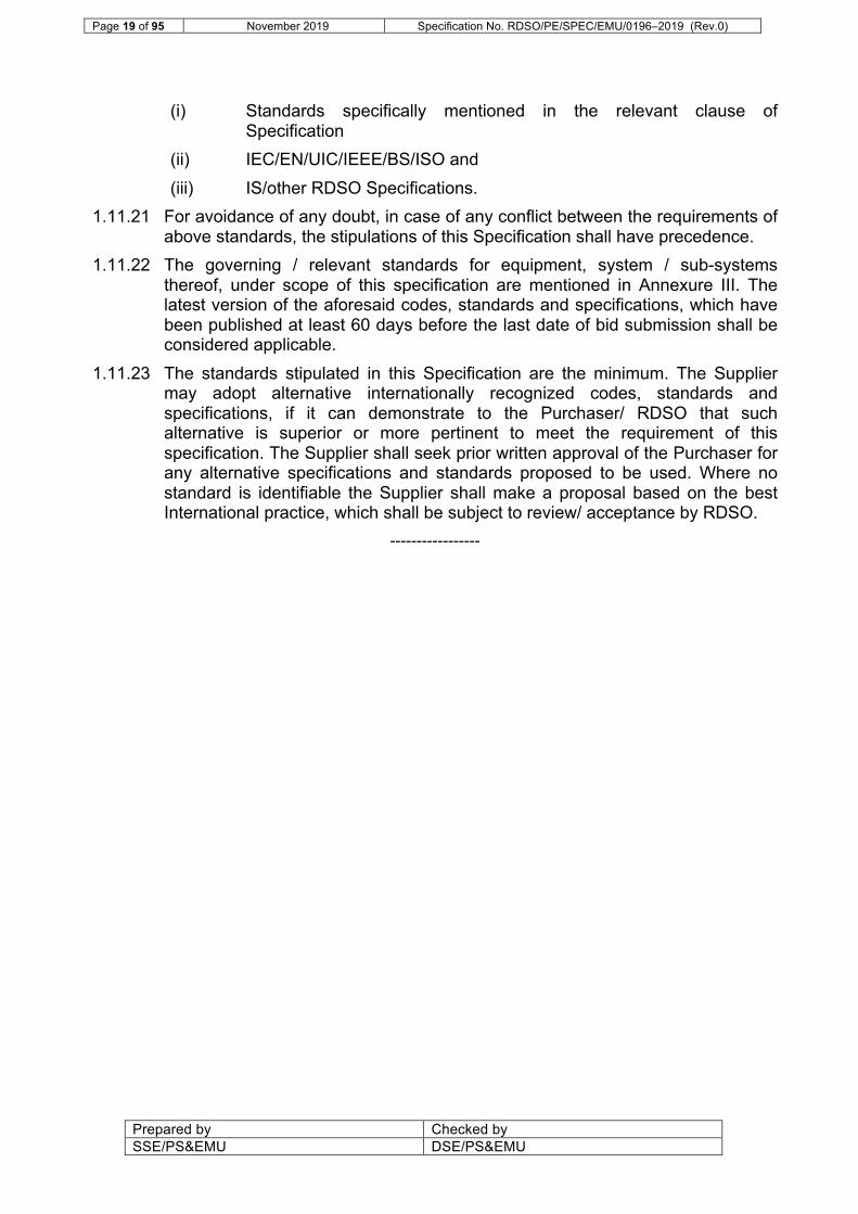
(i) Standards specifically mentioned in the relevant clause of Specification
(ii) IEC/EN/UIC/IEEE/BS/ISO and (iii) IS/other RDSO Specifications.
1.11.21 For avoidance of any doubt, in case of any conflict between the requirements of above standards, the stipulations of this Specification shall have precedence.
1.11.22 The governing / relevant standards for equipment, system / sub-systems thereof, under scope of this specification are mentioned in Annexure III. The latest version of the aforesaid codes, standards and specifications, which have been published at least 60 days before the last date of bid submission shall be considered applicable.
1.11.23 The standards stipulated in this Specification are the minimum. The Supplier may adopt alternative internationally recognized codes, standards and specifications, if it can demonstrate to the Purchaser/ RDSO that such alternative is superior or more pertinent to meet the requirement of this specification. The Supplier shall seek prior written approval of the Purchaser for any alternative specifications and standards proposed to be used. Where no standard is identifiable the Supplier shall make a proposal based on the best International practice, which shall be subject to review/ acceptance by RDSO.
-----------------
Page 20 of 95 November 2019 Specification No. RDSO/PE/SPEC/EMU/0196–2019 (Rev.0)
Prepared by Checked by SSE/PS&EMU DSE/PS&EMU
Chapter 2 : OPERATING AND SERVICE CONDITIONS; DESIGN CONSTRAINTS
2.1 Leading Particulars:
For leading particulars of the Chair Cars, on which supplied equipment are to be fitted, following ICF Car layout OGA drawings may be referred: (Annexure: X) (i) TRAIN 18/DTC/AC-9-0-001 (ii) TRAIN 18/MC/AC-9-0-001 (iii) TRAIN 18/TC/AC-9-0-001 (iv) TRAIN 18/NDTC/AC-9-0-001
2.1.1 The layouts for sleeper coaches are under finalization and will be made available at appropriate stage.
2.1.2 Maximum permissible axle load under fully loaded conditions for all types of cars shall be 17t.
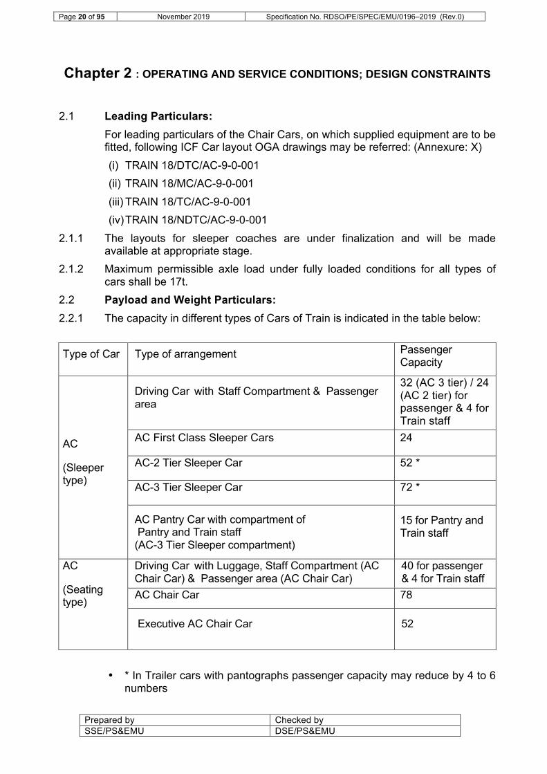
2.2 Payload and Weight Particulars: 2.2.1 The capacity in different types of Cars of Train is indicated in the table below: Type of Car Type of arrangement Passenger
Capacity
AC
(Sleeper type)
Driving Car with Staff Compartment & Passenger area
32 (AC 3 tier) / 24 (AC 2 tier) for passenger & 4 for Train staff
AC First Class Sleeper Cars 24
AC-2 Tier Sleeper Car 52 *
AC-3 Tier Sleeper Car 72 *
AC Pantry Car with compartment of Pantry and Train staff (AC-3 Tier Sleeper compartment)
15 for Pantry and Train staff
AC
(Seating type)
Driving Car with Luggage, Staff Compartment (AC Chair Car) & Passenger area (AC Chair Car)
40 for passenger & 4 for Train staff
AC Chair Car 78
Executive AC Chair Car 52
• * In Trailer cars with pantographs passenger capacity may reduce by 4 to 6 numbers

Page 21 of 95 November 2019 Specification No. RDSO/PE/SPEC/EMU/0196–2019 (Rev.0)
Prepared by Checked by SSE/PS&EMU DSE/PS&EMU
2.2.2 Weight of 70 kg (including 10 kg for luggage) has been considered per passenger for arriving at gross weight of Train.
2.2.3 The capacity indicated above is indicative and the Supplier shall jointly endeavour with Purchaser to finalise the equipment layout on the coaches optimizing on the space available and weight balancing in each Car.
2.2.4 Weight Distribution (i) All equipment/ materials under the scope of supply shall be so
designed that the total overall axle load of the motor or trailer coach under fully loaded condition, fitted with the three-phase propulsion and other accessories does not exceed 17 tons after taking into consideration the unbalancing during tare and gross load conditions.
(ii) Supplier shall submit weight disposition of all equipment in different Cars and shall submit calculation of overall centre of gravity with respect to bogie centers at the design stage. This shall also include calculation for unbalance of load under tare load and gross load conditions on both the bogies. Distribution of weight across the length of the coach shall be such that the axle load duly taking into account all the unbalance forces should not be more than the maximum limit of the axle load.
(iii) The power equipment viz. traction converter, traction motor & transformer etc. shall be distributed amongst adjacent Cars for optimized weight distribution and reduced axle load within the basic unit. Supplier shall ensure that proposed arrangement shall be as per international practice and shall be in line with the basic guidelines as indicated above. As such the distribution of weight shall have to be compatible with the mechanical structure of the Cars, which shall be manufactured by Purchaser.
(iv) Supplier shall submit the relevant references where the proposed arrangement has already been adopted and has been functioning satisfactorily.
(v) The inter-vehicular couplers for high-tension connections between equipment, if used, shall be proven. Such couplers shall be exposed to vandalism activities. As such the coupler shall be designed to cater for all such abnormalities. Details of the coupling arrangement shall be furnished. To ensure safety of personnel, it shall be ensured coupling/ uncoupling of HT & power couplers shall be possible only in de-energised conditions.
2.3 Gauge and Moving Dimensions Unless otherwise stated, the Train set coaches shall conform to the Indian Railways Schedule of Dimension – 1676 mm gauge of 2004 with latest amendments.
2.4 Track Geometry 2.4.1 In this Clause, the references to Group A, Group B, Group C, Group D and
Group E mean the following: (i) Group A: Track with a permitted speed up to 160km/h.

Page 22 of 95 November 2019 Specification No. RDSO/PE/SPEC/EMU/0196–2019 (Rev.0)
Prepared by Checked by SSE/PS&EMU DSE/PS&EMU
(ii) Group B: Track with a permitted speed up to 130km/h. (iii) Group C: Suburban sections of track in Mumbai, Delhi and Kolkata. (iv) Group D: Sections of track where the permitted speed is 100 km/h at
present. (v) Group E: Sectional and branch line where the present permitted speed is
less than 100 km/h. 2.4.2 Trains shall be designed to operate on Indian Broad Gauge track with a spacing
of 1676 mm between the two running rails. 2.4.3 Trains shall operate on horizontal curves with a radius of 152.4 m or greater.
Trains shall be capable of traversing horizontal reverse curves consisting of two 152.4 m radius curves (one in each direction) separated by any length (including zero) of straight track.
2.4.4 Trains shall operate through turnouts, the sharpest of which may be a 6400 mm overriding switch (curved) BG for 60 kg (UIC) or 52 kg rail for 1 in 8½ (crossing angle, tan θ) turnout on pre stressed concrete sleepers.
2.4.5 Trains shall operate on routes with the following maximum super elevation: (i) 165 mm for Group A routes with the exception that 185 mm may be used in
special cases. (ii) 165 mm for Group B and C routes. (iii) 140 mm for Group D and E routes.
2.4.6 The Trains shall operate under the following conditions of cant deficiency:
• 100 mm for Group A and B routes.
• 75 mm for Group C, D and E routes. 2.4.7 The Trains may operate on routes with a maximum gradient of 1 in 37 at
restricted sectional speed without any assisting/ banking locomotives. 2.5 Maximum Speed
(i) Maximum service speed : 160 Km/h (ii) Maximum test speed : 180 Km/h
2.6 Traction Power Supply System 2.6.1 The 25 kV AC Traction power supply has following general features:
Nominal supply voltage 22.5 kV (rms), 50 Hz, single phase, AC
Variation in supply voltage 19 kV to 27.5 kV (rms) Voltage range for Train to operate in full compliance with these Specification and Standards
22.5 kV to 27.5kV
Occasional maximum voltage 30 kV (rms) Occasional minimum voltage 17 kV (rms) Normal variation in frequency ± 3% (48.5 to 51.5 Hz) Stagger of the contact wire ± 200mm on straight track
Up to +300mm on curves

Page 23 of 95 November 2019 Specification No. RDSO/PE/SPEC/EMU/0196–2019 (Rev.0)
Prepared by Checked by SSE/PS&EMU DSE/PS&EMU
Normal contact wire height in mid span 5.5 m from Rail Level
Max. contact wire height 5.8 m from Rail Level Min. contact wire height 4.54 m from Rail Level Neutral Sections After every 25 to 50Kms
Block Section There may be 3 - 4 block sections on each side fed by the traction substation.
Max. continuous OHE current rating 600 Amps. 2.6.2 The guaranteed performance shall be available from 22.5 kV to 27.5 kV for
gross train weight of 550 ton plus weight of equipment covered under this specification to be supplied by Supplier. The maximum current drawn by a 16-car loaded Train to meet the performance requirements of this specification at 22.5 kV shall not exceed 540 Amp. Regenerative braking system shall continue to operate when the supply voltage is in the range from 17kV to 30kV. Train operation shall be feasible at OHE voltage of 17 kV, may be with restricted power. It should be possible to run the Train up to 24-car formation with suitable parametric changes to take care of OHE limitations.
2.7 Overhead Equipment 2.7.1 25 kV AC Traction: The overhead equipment (OHE) from which basic unit shall
be drawing power through pantograph, is supplied through 2-phase grid system and step up/down transformers at the traction substations. Consecutive sections are not supplied from the same phase, therefore neutral sections are provided in between the traction feed from two adjacent substations. The length of the neutral section may be up to 42 meter. The OHE can be of regulated (fit up to 160 kmph) or unregulated type (fit up to 110 kmph).
2.7.2 Limit of Second Harmonic: The second harmonic current of each motor coach shall not exceed 0.5A and shall be governed by international standard (IEEE 519-1992). The Supplier shall submit curves of harmonic currents vs load current per motor coach and per basic unit for rake configurations given in Clause 1.3.12.
2.8 Power Factor Train shall achieve a minimum power factor of 0.98 as measured at the pantograph. The power factor shall be governed by EN 50388.
2.9 Fire Safety 2.9.1 The design and manufacturing of equipment shall be in accordance with EN
45545. The applicable Hazard level will be HL 2 to Trains having sitting passengers only, whereas HL3 will be applicable to Trains having sleeper type coaches. Also refer to Clause no. 4.18.8 of this Specification.
2.9.2 A reliable Automatic fire detection and alarm system shall be provided, in accordance with Clause 4.19 of this specification covering all the onboard cabinets housing electrical switchgears/ equipment.

Page 24 of 95 November 2019 Specification No. RDSO/PE/SPEC/EMU/0196–2019 (Rev.0)
Prepared by Checked by SSE/PS&EMU DSE/PS&EMU
2.9.3 RDSO specification No. RDSO/2008/CG-04 Rev 05 may be referred for guidance for suitable fire detection technologies. Necessary interface with TCMS shall be finalized at design stage.
2.9.4 Multi-levels of alarms for fire detection shall be used. For reference purpose Carriage Directorate Specification no. RDSO/2008/CG-04 (Rev.5) may be referred for various stages of alarm for reference purpose. The clauses of this specification not relevant to Train set will not be applicable and issue related to interface of fire and smoke detection system with TCMS will be finalized at the detailed design stage.
2.10 Ingress Protection 2.10.1 All equipment shall be suitably protected from dust and water. As a minimum,
equipment shall be sealed to the standards stated below.
• Under frame & externally mounted equipment : IP65 (other than traction/ auxiliary converter/Traction Motor)
(Battery Box and Brake Chopper can be with IP 20 protection)
• Equipment mounted inside the Car body : IP54 2.10.2 The degree of protection applicable for different equipment has been specified
in respective clauses. 2.11 Climatic and Environmental Conditions
(i) Relative Humidity: up to 100% saturation during monsoon season. (ii) Ambient temperature max. : 50º C min. : -10º C (iii) The temperature of stationary Car in sun may go as high as 70º C.
The equipment shall not be adversely affected in any way due to exposure to such high temperatures. Supplier shall furnish the precautions taken in equipment/component selection in order to conform to this requirement. The Supplier will indicate the expected temperature rise of equipment under the reference site conditions described above and shall submit the expected MTBF/MDBF at such temperature. Refer Annexure IX.
(iv) The equipment shall function in accordance with this Specification following any period when stationary at the maximum ambient temperature and in full sunlight as specified in this clause, in other words any pre-cooling of equipment shall not be required.
(v) Altitude (Max): 1600 meter (vi) Rainfall: Very heavy and continuous at any rate between 0 and 100
mm / hour (up to 2500mm during rainy season) (vii) All under slung equipment shall be designed suitably to ensure its
normal working even in adverse conditions as mentioned in this Clause.
(viii) Atmosphere during hot weather: Extremely dusty, humid and salty. The Train shall be working in coastal area also and thus may be continuously exposed to highly corrosive, salty atmosphere along with industrial pollutants.

Page 25 of 95 November 2019 Specification No. RDSO/PE/SPEC/EMU/0196–2019 (Rev.0)
Prepared by Checked by SSE/PS&EMU DSE/PS&EMU
(ix) The equipment shall function in accordance with this Specification when subjected continuously to an atmosphere containing dust in concentrations up to 1.6 mg / m3.
(x) The equipment shall function in accordance with this Specification when subjected continuously to a humid and salt laden atmosphere with maximum pH value of 8.5, sulphate content of 7 mg per litre, maximum concentration of chlorine 6 mg per litres and maximum conductivity of 130 micro Siemens / cm.
(xi) The equipment shall function in accordance with this Specification when subjected to high wind speed in certain areas, with wind pressure reaching 150 kg/m2.
(xii) Equipment shall function in accordance with this Specification when exposed to solar radiation in the range from 0 kW/m2 to 1 kW/m2.
(xiii) Special care shall be taken to ensure no damage to equipment due to deposition of atmospheric salts and industrial pollutants. Supplier shall enclose the details of specific measures adopted to ensure the satisfactory working of equipment against the deposition of salts & industrial pollution.
(xiv) Vibrations: Because of track irregularities, level of shocks and vibrations to which traction motors are exposed are far more than actually given in IEC for TM mounting arrangement. Supplier to carry out instrumented trials if considered desirable on existing stock for measurement of shocks and vibrations in consultation with RDSO at design stage. The suspension system and the mounting arrangement of underslung / bogie mounted equipment shall be so designed that the equipment performance is not adversely affected due to such high vibrations and shocks.
2.12 Signal and Telecommunication Installations: 2.12.1 The tracks over which the Train will run will be equipped with 50 Hz AC track
circuits, 83.33 Hz AC track circuits, digital axle counters, DC track circuits as well as track circuits at higher frequencies including audio frequency track circuits and AWS/AAWS. The design of the power electronics and control electronics provided on the equipment and Train shall be such as not to cause unacceptable level of interference on these track circuit and on the installed S&T equipment. Acceptable level of interference and psophometric current limits for rake configurations in worst possible condition are mentioned in Annexure V.
2.12.2 It may be noted that acceptable limits are indicated for one motor coach and also for complete rake. The Supplier shall ensure that even in worst possible combination in service conditions the overall limit prescribed per rake are adhered to. The Supplier shall submit at design stage the simulation results of the likely value of harmonic currents of fully loaded Train with the formation as mentioned in Clause 1.3.12 and will also include the worst conditions of Motor coach isolation as above.
2.12.3 The values of the currents for complete rake under the worst possible conditions shall be measured. The Supplier shall furnish detailed procedure,

Page 26 of 95 November 2019 Specification No. RDSO/PE/SPEC/EMU/0196–2019 (Rev.0)
Prepared by Checked by SSE/PS&EMU DSE/PS&EMU
any special condition of measurements and specific instrumentation required for the purpose. It shall be the responsibility of the Supplier to arrange the instrumentation in order to conduct the measurements. The procedure shall be furnished by the Supplier and shall be finalized with the approval of RDSO. The tests shall also include the cases of isolation of motor coach/ basic units during service. These tests shall be conducted on the prototype rakes only.
2.12.4 On the communication network, control circuits, tele-printer circuits, as well as VHF/UHF and micro-wave circuits are employed. Broad details of such equipment used are given in Annexure VI.
2.12.5 The design of the power electronics and control electronics provided on the Train shall meet the requirements as above.
2.12.6 EN 50238 is currently under revision and shall include interference current limits for track circuits and axle counters. Where these overall interference current limits are more onerous than those stated in Annexure V of this Specification, these limits shall be applied subject to the provisions made in Clause no. 1.11.22 of this Specification.
2.12.7 IR is going for advanced Train protection system in a gradual manner. It is likely to have following features:
(i) TCAS (RDSO specification RDSO/SPN/196/2012 ver 3.2 dated 17.05.2017 may be referred for guidance).
(ii) The dimensions of the on-board equipment shall be finalised at design stage.
(iii) The Supplier shall coordinate with the OEM of TPWS/TCAS for suitable arrangement/interface for Brake interface arrangement and interface of track-side equipment. IR will facilitate the co-ordination between OEM and the Supplier.
2.13 Reliability, Availability, Maintainability and Safety (RAMS) 2.13.1 General
The supplier shall ensure Guaranteed Reliability, Guaranteed Availability and high degree of safety in order to provide a dependable service. The optimization of the system with respect to Reliability, Availability, maintainability and safety shall form an integral element of this Specification.
2.13.2 The plan for Reliability, Availability, maintainability and safety shall conform to EN 50126/ IEC 61709/ IEC 62278. Reliability of electronic components shall conform to IEC 61709.
2.13.3 The supplier shall develop RAMS targets both for the complete system and for the major Sub-systems such as transformer, traction converter, auxiliary converter, electronics, traction motor, Transmission and Suspension System, high voltage equipment, blowers and other auxiliary machines, such that it will provide a high level of dependability. RAMS targets shall also be developed for bought out items.
2.13.4 After rectification of any failure / fault, the concerned equipment / system should resume its original performance / function.

Page 27 of 95 November 2019 Specification No. RDSO/PE/SPEC/EMU/0196–2019 (Rev.0)
Prepared by Checked by SSE/PS&EMU DSE/PS&EMU
2.13.5 Components critical for safety shall fail into safe operating mode in case of malfunctioning. The system safety plan shall identify and list safety critical components and this list shall be updated periodically.
2.13.6 The Supplier shall establish and operate a detailed reliability, availability, maintainability and safety (RAMS) Assessment system in support of the design, manufacture and subsequent testing, commissioning, operation and maintenance of the equipment.
2.13.7 Safety Assessment shall be carried out and shall include the following principles: (i) Degraded modes and emergency operations as well as normal operations
shall be considered; (ii) Safety risk assessment shall utilize more than one methodology to assess
risks; and (iii) Safety risk assessment shall include the consideration of dependent
failures, in particular the traction power, braking and control systems. 2.13.8 Every complete basic unit, as well as each constituent component, assembly,
subsystem and system element shall be designed in such a manner as to perform its function reliably in service. To ensure reliability of the system, redundancy shall be built-in so that: (i) The brake performance i.e. electro-pneumatic (EP) as well as
regenerative brake force of 16-Car Train shall not deteriorate in case of failure of one Brake Electronics Control Unit. However, BP controlled back-up brakes shall always be available on the Train;
(ii) The Basic Unit control of each Traction converter shall be independent;
(iii) Further, the redundancy shall be built-in so that the performance of the rake shall not deteriorate in the event of failure of auxiliary supply system equivalent to that of one Basic Unit.
(iv) No single-point failure shall cause complete failure of the traction system, auxiliary supply system or inability to control the brakes on Train. Further every traction and auxiliary converter shall have independent control and cooling arrangement to avoid single point failure leading to complete failure of traction/auxiliary system at basic unit level.
(v) Where the system design of the equipment incorporates component redundancy as the method of reducing the consequences of a single point failure, such redundancy shall not allow hidden faults to remain undetected.
2.13.9 Supplier shall submit the basic maintenance schedules of the proposed equipment. Minimum interval between two maintenance schedules in the depot for the equipment supplied should not be less than 90 days except for activities which can be done outside the base depot (such as cleaning of filters mounted not in the under-frame, for which the periodicity shall not be less than 15 days) and 3 years for major works in workshop/major depot. Details to be worked out

Page 28 of 95 November 2019 Specification No. RDSO/PE/SPEC/EMU/0196–2019 (Rev.0)
Prepared by Checked by SSE/PS&EMU DSE/PS&EMU
during detail design stage. Average running distance of a rake may be considered as 2000 kilometer per day. The maintenance program prepared by Supplier shall have the following objectives ascertaining the above periodicity of maintenance schedules:
• Enhancement of availability
• Minimization of maintenance costs
• Minimization of coach downtime/MTTS (meantime to restore serviceability) 2.13.10 Based on the proposed maintenance schedules, the Supplier will submit
average downtime on account of scheduled maintenance for the equipment to be supplied excluding the time required for transfer of rake to and from the maintenance depot. Ineffective on this account should not exceed two percent. Supplier should also submit an estimate for the downtime for unscheduled maintenance in respect of equipment to be supplied. The Supplier shall assess and submit the figure for ‘total percentage ineffective’, in terms of percentage of rakes expected to be ineffective/unserviceable due to schedule and unscheduled repairs/maintenance of equipment supplied (excluding the time taken for transfer of the rakes to and from maintenance depot) against the total number of rakes fitted with the equipment under his scope of supply. This ineffective figure shall not exceed FOUR percent in any week (Monday-Sunday) calculated on 24 hourly basis. If during the test and service trial period of prototype rakes, it is experienced that downtime due to unscheduled repairs/scheduled maintenance of the equipment supplied is excessive, supplier shall be required to take suitable remedial measures to bring the ineffective figure within the limit submitted during the design approval stage.
2.13.11 Modular design principles shall be employed. Requirements for adjustments after module interchange shall be avoided except as required in the specification.
2.13.12 All systems, components and structural areas serviced as part of inspection or periodic preventive maintenance shall be conveniently accessible for service and inspection.
2.14 Adhesion Limits: The equipment shall be so designed that the coefficient of adhesion requirement does not exceed 20% during powering & regenerative braking and 16% during only pneumatic braking under all requirements of performance as specified in this specification.
-----------------

Page 29 of 95 November 2019 Specification No. RDSO/PE/SPEC/EMU/0196–2019 (Rev.0)
Prepared by Checked by SSE/PS&EMU DSE/PS&EMU
Chapter 3 : PERFORMANCE REQUIREMENTS
3.1 Performance Requirements 3.1.1 General Description
(i) The capacity of the traction motor and the other equipment shall be adequate to permit continuous operation of 16-car train comprising 4 basic units of total weight 550 ton and items covered under scope of supply of this specification (all items mentioned in clause 4.1 to be considered) to be supplied by Supplier so as to meet the performance requirements specified herein. The design shall permit the operation of Train up to 24 cars under loaded conditions with the unit weight as above. All performance calculations/ evaluations shall be with respect to 16-Car train having four basic units unless stated otherwise.
(ii) The entire equipment shall be designed to ensure satisfactory and safe operation under the running conditions specified in Chapter 1 & 2, abnormal conditions such as sudden voltage variation, load variation, short circuits and varying track & weather conditions. The design shall also facilitate erection, inspection, maintenance and replacement of the various units comprising the equipment.
(iii) All working parts of the control and auxiliary circuit shall be suitably covered to keep them free from moisture and dust without compromising on safety and reliability.
(iv) All the electrical equipment shall comply with the latest editions of IEC specifications unless otherwise specified. The temperature rise shall be measured according to the procedure stipulated by IEC and shall comply with limits specified in this specification.
(v) The train performance including waterproofing shall be guaranteed over complete range of the wheel diameter. Minimum clearances as specified in Clause 3.10 shall be ensured under fully worn out condition of wheel.
3.1.2 The acceleration requirements at maximum load on level tangent track, according to stipulations of Clause 3.2 shall be fulfilled at an average OHE voltage of 22.5 kV to 27.5 kV.
3.1.3 Supplier shall submit the RMS current values of traction motor and temperature rise of propulsion equipment for a 16 Car rake operation for repeated all-out cycles of 10 KM with a dwell time of 30 sec up to stabilization of temperatures of all propulsion equipment. The R.M.S. (root mean square) loading of the traction motor with regenerative braking in use for all out running as mentioned herein shall not exceed the continuous rating of the traction motor.
3.2 Traction Performance 3.2.1 The Traction performance shall be achieved for maximum gross weight of 550
ton plus weight of items in the scope of this specification (all items mentioned in clause 4.1 to be considered) to be supplied by Supplier for 16-car train.

Page 30 of 95 November 2019 Specification No. RDSO/PE/SPEC/EMU/0196–2019 (Rev.0)
Prepared by Checked by SSE/PS&EMU DSE/PS&EMU
3.2.2 All requirements specified shall be achieved when the Train is loaded as per EN 12663 / EN 15663 for the whole service range of wheel diameter.
3.2.3 All requirements specified shall be achieved when the overhead line voltage is as per Clause 2.6 of this Specification.
3.2.4 Train shall be capable of achieving an average acceleration of 0.70 m/s2 for speed up to 40 km/h, subject to the requirements with respect to jerk rate specified in Clause 3.4 of this Specification.
3.2.5 Train shall be capable of achieving a minimum residual acceleration of 0.1 m/s2 at 160 km/h.
3.2.6 Train shall be capable of accelerating to a speed of 160 km/h in a maximum of 140 seconds.
3.2.7 There should be time saving in the range of 20% with permissible variation of 10% on negative side in journey time corresponding to maximum service speed of 130kmph, when running in all out mode on existing section of HWH-NDLS & NDLS-HWH to be established through simulation. Speed Restrictions, Curve and Gradient details of HWH-NDLS section is enclosed as Annexure- IV. For comparison, time table of existing Rajdhani Train is enclosed as Annexure – VII
3.2.8 Train Resistance: The rolling resistance formula shall be referred for reference as mentioned in clause 3.8.
3.2.9 For estimation of temperature rise of propulsion equipment, repeated all-out cycles of 10 km in loaded condition with dwell time of 30 sec till stabilization of all relevant temperatures, shall be used. Train shall be speeded up to 160kmph with full traction, maintain maximum service speed for required distance and then apply full service brake till standstill. On completion of the test as above the temperature of all equipment shall remain within respective permissible limits.
3.3 Brake System Performance 3.3.1 All requirements specified in this clause shall be achieved when the Train load
is as given in clause 2.2. 3.3.2 Train shall, achieve a minimum deceleration of 0.8 m/s2 during full service
braking following the jerk limit as specified in clause no.: 3.4. 3.3.3 Train shall achieve a uniform full service braking across the whole speed rage
from 0 to 160 km/h. The full service brake shall not achieve deceleration of greater than 1.0 m/s2 at any speed.
3.3.4 Train shall be fitted with an emergency brake, which can bring the Train to standstill in less than 1250 m when the Train is travelling at 160 km/h.
3.3.5 Specified brake performance shall also be achieved in case of failure of regenerative braking.
3.4 Jerk Limit Under all normal operating conditions, the rate of change of acceleration or deceleration shall not exceed 0.7 m/s³. Failure of the jerk limiting system shall not limit braking effort. Emergency brake applications and any associated ramp out of propulsion shall not be jerk limited. Reduction of propulsion effort due to a power interruption (including passing through neutral sections) need not be jerk

Page 31 of 95 November 2019 Specification No. RDSO/PE/SPEC/EMU/0196–2019 (Rev.0)
Prepared by Checked by SSE/PS&EMU DSE/PS&EMU
limited. The sampling rate for jerk assessment i.e. the duration for which jerk limit of 0.7 m/s³ is to be observed will be decided at the design stage.
3.5 Ratings of equipment 3.5.1 The continuous rating of the traction converter, traction motor & the traction
transformer shall be based on the criteria specified in Clause no. 3.1.3.The rating of equipment shall be demonstrated by thermal simulation and measurement during combined system testing as well as vehicle testing in the field. The procedure adopted for calculation of propulsion equipment ratings including the boundary conditions shall be submitted.
3.5.2 Supplier shall submit detailed calculations of maximum power loading of all major components of the traction system including the maximum rms currents, tractive/braking effort and motor torque for both motoring and braking. During traction mode, maximum auxiliary power shall be taken into account and during braking mode minimum loading of auxiliary power shall be considered. While deciding the ratings of the equipment, Supplier shall ensure that the performance of the complete Train shall conform to the conditions laid down in this specification.
3.5.3 Supplier shall submit the time, distance, maximum power, OHE current, energy consumed and energy regenerated in graphical as well as tabular form for one all-out cycle of 110, 130, 160 and 180 kmph in fully loaded condition. Performance parameters for one basic unit isolated condition shall also be submitted.
3.5.4 Efficiency curves of all equipment and tractive effort/braking effort (in kN) of a basic unit shall be furnished along with overall system efficiency curves. The total auxiliary power shall be furnished as break up of power requirement for lights, air-conditioning loads, auxiliary power required for propulsion system and control electronics.
3.5.5 The temperature rise of the propulsion equipment shall not exceed the permissible value. All the temperatures calculated on the basis of repeated runs/continuous duty cycles shall be deemed as stabilized temperatures. The temperature rise of propulsion equipment shall be demonstrated by thermal simulation and measurement during combined system testing as well as vehicle testing in field. The simulation result of temperature rise of propulsion equipment shall also be submitted considering only regenerative braking except very low speeds in the above runs.
3.5.6 The fully loaded 16-car rake with one basic unit isolated and already running continuously at sectional speed shall be capable of starting on a gradient of 1 in 37 and clear the section of 10 Km with speed up to 60 kmph. The temperature rise of the traction motor and other propulsion equipment shall be within thermal rating of the respective equipment as specified in Chapter 4. The one-hour rating of the Traction Motor shall be submitted. Average line voltage during the period shall be taken as 22.5kV AC under traction. The time, in which the section will be cleared and the maximum speed attainable shall be furnished by the Supplier. Supplier shall submit simulation results for the propulsion equipment temperature rise under the above conditions as per the Annexure II.

Page 32 of 95 November 2019 Specification No. RDSO/PE/SPEC/EMU/0196–2019 (Rev.0)
Prepared by Checked by SSE/PS&EMU DSE/PS&EMU
3.5.7 The variation of power and TE & BE with OHE voltage in range from 17 kV to 22.5 kV AC, shall be submitted for speeds from starting to maximum speed in steps of 1 kV, during design stage.
3.5.8 The equipment shall be so designed that the coefficient of adhesion does not exceed the limits defined in Clause no. 2.14 during powering or braking. Supplier shall furnish the optimized value of coefficient of adhesion and the reason thereof.
3.5.9 Specified temperature rise of equipment as specified in Clause no. 3.5.5 shall be calculated after taking into account at least 25 % choking of air filters and radiator fins.
3.5.10 Regenerated Energy: The regenerated energy for all out running (full traction up to max. service speed followed by full service braking up to standstill) shall not be less than 27 % of the energy consumed during powering at the specified voltage in Clause 2.6 of this Specification. Acceleration and braking rates shall be as defined in Clause 3.2& 3.3 of this Specification and full auxiliary load shall be taken into account except emergency load, RMPU & Pantry loads. Duty cycle of compressors shall be taken as 100% during the test. The net energy consumed or regenerated at the pantograph shall be used for calculating percentage regeneration energy. In the event of failure of one Basic Unit/ equipment less than or equivalent to that of one Basic Unit, reduction in the value of regenerated energy shall not be more than their proportionate value.
3.5.11 Efficiency 3.5.11.1 The peak efficiency of traction system consisting of traction transformer, traction
converter (line side converter and drive side inverter) and traction motor shall not be less than 87% at one operating point in the maximum power zone of the driving operation characteristics under loading conditions specified in clause 2.2 with a line voltage as per clause 2.6. The efficiency of the traction system shall be calculated duly taking into account the energy consumed by the associated cooling equipment viz. blowers, pumps etc. of transformer, traction converter, traction motor etc. Efficiencies by running at constant speeds of 45, 110, 130 and 160 kmph shall also be measured and recorded. The measurement of the efficiency shall be performed on the combined test bed with full complement of equipment and shall be governed by IEC 61377.
3.5.11.2 The efficiency of the complete auxiliary converter system including sine filter shall not be less than 94% at full load. Complete system shall also include input inductors and output transformers (if any) provided as per clause 4.25. The efficiency of the auxiliary converter shall be calculated dully taking into account energy consumed by itself from auxiliary supplies e.g. for cooling equipment — fans, pumps, etc. The measurement of the efficiency shall be performed on the combined test bed and shall be governed by IEC 61377 and 61287. Further the efficiency shall also be validated during vehicle type test.
3.5.11.3 Efficiency of the traction equipment shall be calculated taking into account energy consumed by auxiliary supplies (e.g. for cooling equipment – fans, pumps etc.)
3.5.12 Continuous Operating Equipment

Page 33 of 95 November 2019 Specification No. RDSO/PE/SPEC/EMU/0196–2019 (Rev.0)
Prepared by Checked by SSE/PS&EMU DSE/PS&EMU
3.5.12.1 The capacity of the traction motors and equipment under continuous duty cycle shall be adequate to permit continuous and punctual operation of fully loaded Train under the operating and service conditions prevailing on IR.
3.5.12.2 Supplier shall submit the balancing speed for the fully loaded 16-Car train in normal and one basic unit isolated condition.
3.6 Neutral Section (i) Neutral section is provided in the AC traction area. Suitable
arrangement shall be provided by the supplier to ensure that the loss of main power for each basic unit, while negotiating neutral section, is restricted to bare minimum. The supplier shall ensure compatibility of their equipment with the trackside equipment, already installed by IR and in use at the neutral sections.
(ii) The system shall ensure safe opening and closing of the circuit breakers of basic units sequentially while approaching and leaving the neutral section respectively.
3.7 Interference to Signal and Telecommunication Installations There shall not be any interference to signal and telecommunication installations as mentioned in Clause no. 2.12.
3.8 Train Resistance: Rolling resistance formula (Ref: RDSO Testing dte. Report: RDSO / 2019 / TG / MT –1638 /F /Rev. – 0/ Amendment – NIL, Dated 02.09.2019) is mentioned as under for reference: R = 2.4308+ 0.0038*V+ 0.0001V*V (kg/t) R is the resistance in Kg/ton, and V is the speed in kmph.
3.8.1 Starting Train resistance: The starting train resistance for motor and trailer coaches may be taken as 4 kg/t.
3.8.2 The performance calculations shall be done with the train resistance formulae as indicated above.
3.9 Equipment Layout (i) Supplier shall design the equipment in such a way that enough space is
available for the maintenance works. (ii) Fitment of all equipment will be so decided that the body weight is properly
distributed so that the axle load is within permissible limits after taking into consideration unbalance during the tare and fully loaded conditions.
(iii) Control equipment for the driver will be required to be provided in the driving cab.
3.10 Minimum Clearance from Rail Level Under fully worn wheels and fully loaded condition of the coach, the minimum clearance of bogie-mounted equipment from rail level shall be more than prescribed in (IRSOD ACS 27 of July 2019) under worst conditions. The

Page 34 of 95 November 2019 Specification No. RDSO/PE/SPEC/EMU/0196–2019 (Rev.0)
Prepared by Checked by SSE/PS&EMU DSE/PS&EMU
minimum clearance for the body mounted under slung equipment shall be 215 mm under tare condition with fully worn wheels.
--------------

Page 35 of 95 November 2019 Specification No. RDSO/PE/SPEC/EMU/0196–2019 (Rev.0)
Prepared by Checked by SSE/PS&EMU DSE/PS&EMU
Chapter 4 : SCOPE OF SUPPLY & TECHNICAL SPECIFICATIONS
4.1 Scope of Supply 4.1.1 For the design, development including simulation studies, manufacture, supply
and commissioning of complete set of 3-phase drive equipment for 25 kV, 50 Hz air-conditioned BG Train sets, the scope of supply is as under unless stated otherwise in the bid document/ purchase order (in the event of non-inclusion of any item indicated hereunder, the accountal of respective weight shall continue as though in the scope of Supplier): (i) Traction transformer with required number of secondary traction
windings along with protection equipment. (ii) Gapless lightning arrestors, Current transformer and Potential
transformer for 25kV AC. (iii) IGBT based PWM Traction Converter set including DC link with 100
HZ resonance filter (optional) and/or any other equipment necessary to reduce the effect of other harmonics on S&T equipment.
(iv) Three-phase induction motors compatible with IGBT based traction converter power supply, with coupling, gear box assembly, sensors and associated equipment
(v) Microprocessor based Train Control and Management System (TCMS) including fault diagnosis and display system in the driving cab.
(vi) Submission of complete Bogie design duly tested by structural as well as dynamic simulation and validation software as per details given in para 4.7 including fabrication and supply of complete bogie assemblies for two prototype rakes.
(vii) Train Control & Management System, multiplexing system for relevant control & other signals and any other equipment, cables, inter-vehicular couplers & terminal equipment. Inter-vehicular couplers shall be supplied in assembled form.
(viii) Event Recorder (ix) Voice communication system, Passenger information system
including coach displays, audio communication system, emergency talk back system and interface with the Train Monitoring System (TMS) and any equipment required for interfacing PIS with the Receiver-equipment of TMS. Receiver Equipment of existing TMS is in the scope of supply of the Purchaser and may be mounted in the driving cab. The specification shall be made available to the Supplier at the design stage, if required.
(x) Emergency Talk Back Unit (ETB) (xi) Passenger Car Surveillance system with facility to stream video in
central server. (xii) Cab recording equipment

Page 36 of 95 November 2019 Specification No. RDSO/PE/SPEC/EMU/0196–2019 (Rev.0)
Prepared by Checked by SSE/PS&EMU DSE/PS&EMU
(xiii) Integration with TCMS of Brake system and Automatic door closure system
(xiv) Master cum Brake controller (xv) Complete pre-fabricated driver desk housing all the necessary
equipment and driver/ guard seat. Cab radio may be provided by IR for sections with GSM-R.
(xvi) Automatic smoke/fire detection system (xvii) Speed Indicating cum recording equipment (xviii) Passenger alarm system (xix) Control Equipment such as relays, contactors, circuit breakers and
related switchgears etc. for propulsion system, controls, auxiliaries in the assembled form viz. cubicle or cabinet.
(xx) Brake Interface Unit fulfilling the brake blending requirements. (xxi) Wheel slip/ slide control (xxii) Load weighing system including redundant weight sensors at bogie
level. The scope of supply of pressure transducers shall be with Supplier.
(xxiii) High Voltage cable including isolation & protection system for feeding adjacent units
(xxiv) Auxiliary system including IGBT/ SiC power module based Auxiliary converter for auxiliary supplies,
(xxv) Battery and battery charging system (xxvi) Auxiliary machines such as oil pump, oil cooling blowers for traction
transformer, blowers for traction converter, auxiliary converter etc. (xxvii) Light system including coach lights, Headlight, Tail-light, Marker
lights and Flasher lights etc. including control switchgear thereof. (xxviii) Pneumatic system comprising of main air compressor, air dryer,
filters and auxiliary compressor (xxix) Complete air-conditioning system with necessary equipment such as
Roof Mounted Package Unit (RMPU), control panel, micro-controller etc.
(xxx) Power & control cables including termination equipment. (xxxi) Inter-vehicular couplers (xxxii) Data / communication cables, fire survival cables as mentioned in
relevant clauses. (xxxiii) EPDM & EMC type cable glands for sealing & shielding (xxxiv) Pantograph & Earthing Switches - Single pantograph suitable for
25kV AC supply shall be used on each basic unit. (xxxv) Two VCBs (One with earthing switch for Traction Circuit protection
and one without earthing switch for HT cable protection)
Page 37 of 95 November 2019 Specification No. RDSO/PE/SPEC/EMU/0196–2019 (Rev.0)
Prepared by Checked by SSE/PS&EMU DSE/PS&EMU
(xxxvi) Centralized Coach Monitoring System (CCMS) (xxxvii) APC receiver compatible with existing track magnets (xxxviii) Any other equipment required for power isolation, interlocking &
proper functioning of the traction equipment etc. (xxxix) Instrumentation required for commissioning and field-testing of the
equipment. (May be taken back by the Supplier after completion of the commissioning and field testing activities)
4.2 Technical Specification for 3-Phase Propulsion System and Associated Equipment The 3-phase drive equipment shall be based on the technology proven in successful service applications as per Clause no. 1.4.12. The equipment shall be suitable for regeneration for the full speed range. The broad specification of equipment is furnished below.
4.3 Traction Transformer 4.3.1 A fixed ratio transformer shall be provided with multi traction and/ or auxiliary
windings suiting the requirement of IGBT based traction converter to meet the load of three-phase propulsion and auxiliary equipment & air-conditioning. The kVA rating of the transformer shall be specified at a line voltage of 22.5kV and shall be designed to deliver the power at a total current corresponding to the continuous rated traction motor currents after accounting for the efficiency & power factor of traction motor, traction converter, auxiliary converter for meeting the auxiliary load as specified in the specification Clause 4.28. The guiding principle for calculation of rating shall be as per Clause 3.2. Supplier shall note that the performance is required to be guaranteed for the range of voltage given in the Clause 2.6.
4.3.2 The transformer shall be designed with adequate overload capacity, in accordance with Good Industry Practice, to permit full utilization of the traction motor capacity during powering as well as full regenerative braking and to accommodate the maximum load imposed by the auxiliary supply system (particularly in the event of failure of auxiliary supply equipment fed from other transformers).
4.3.3 The transformer will conform to IEC 60310 and temperature rise limits of the windings and oil shall correspond to IEC 60310 minus 200C under all conditions of operations. Winding conductor of transformer shall be provided with 'H' class enamel and nomex paper insulation.
4.3.4 The secondary windings shall have a very high magnetic de-coupling. 4.3.5 The transformer shall be of modular construction. Provision shall be provided
for letting out the oil from transformer to the underside of the Car in the event of any fault/electrical disturbance in the transformer causing oil to rush out. No part of the transformer shall protrude above Car floor level. The radiator shall be so designed so that cleaning interval is in synchronization with the Scheduled Maintenance. The frequency for dry and wet cleaning of radiator shall not be less than 15 days and 90 days respectively.

Page 38 of 95 November 2019 Specification No. RDSO/PE/SPEC/EMU/0196–2019 (Rev.0)
Prepared by Checked by SSE/PS&EMU DSE/PS&EMU
4.3.6 Adequate care shall be taken in design to take care of the high humidity for long duration (in coastal areas). The silica gel, if used, should not require attention in between the Schedule examination.
4.3.7 The transformer tank, radiators and associated equipment shall be coated with pollution/oil resistant and dust repellant epoxy paint. The lower portion of the tank shall be of adequately strong so as to protect against hitting by extraneous objects/ flying ballasts while on run. The Transformer tank material shall be chosen to ensure lighter weight.
4.3.8 The cooling agent for the transformer shall be K-class, biodegradable, arc resistant and shall have high flash point (> 250 ºC) & high fire point (>300 ºC)
4.3.9 The transformer shall be mounted under slung. 4.3.10 Current transformer, potential transformer and matching overload relay etc.
shall be in the scope of supply of the Supplier. 4.4 Lightning Arrestor 4.4.1 Two metal oxide gapless lightning arrestors shall be provided on the roof of
each Car fitted with a pantograph and/or traction transformer for protection against the line voltage transients caused by lightning and system switching. One lightning arrestor shall be connected to the high voltage circuit between the pantograph & the main circuit breaker and the other shall be connected to the high voltage circuit between the main circuit breaker and the transformer. These gapless lightning arrestors shall have discharge class-4 for primary and 3 for secondary.
4.5 Traction Converter 4.5.1 The four-quadrant traction converter shall be of a proven design and
established in service performance in similar applications, IGBT based with PWM control to ensure regeneration and the power factor near unity. The range of variation of power factor shall be submitted by the Supplier. The traction converter shall be installed underslung and shall have housing made of stainless steel SS304 or anodized sea-water proof aluminum. The traction converter shall be protected against ballast hitting as per the relevant international standards. There shall be no need of painting on housing.
4.5.2 Cooling System Traction converter offered shall be forced air /convection/ oil/ water-cooled.
4.5.3 The voltage rating of IGBT would be so chosen that at least 25 % margin is available after taking into consideration the DC link voltage and voltage jump on account of inductance and capacitance in the circuit. The current rating of IGBT shall be such that the junction temperature has minimum thermal margin of 10°C in the worst loading conditions and under the specified ambient conditions. Supplier shall submit the maximum junction temperature of the devices under worst operating conditions.
4.5.4 The traction converter shall meet the requirements of IEC-61287 & the control electronic and PCBs shall conform to IEC-60571 including compliance to the optional tests. However, due to higher ambient temperature in India, the temperature for dry heat test shall be 80°C as against 70°C specified in IEC/EN. LCD display units may be tested into 70°C. The electronic control equipment

Page 39 of 95 November 2019 Specification No. RDSO/PE/SPEC/EMU/0196–2019 (Rev.0)
Prepared by Checked by SSE/PS&EMU DSE/PS&EMU
should be protected against unavoidable EMI. The equipment shall be suitably mounted in properly designed cabinets for cooling requirements of the electronic equipment (with or without doors) and shall remain in the scope of supply of the Supplier. The vibration and shock tests and endurance tests shall be done as per IEC 61373 as per the requirements of design.
4.5.5 The wheel slip/ slide detection and correction system shall be an integral part of the Train control system and if necessary also of the traction converter which shall capture any excessive acceleration, differential speeds between axles, over speed and any other parameter considered necessary to use the available adhesion on different wheels in most optimum way and minimize wheel slipping / skidding.
4.5.6 The catenary (OHE) voltage fluctuates widely as indicated in the Clause 2.6. The variation of frequency has also been indicated therein. The converter shall be provided with necessary control for the operation under such fluctuations without exceeding the rated cut off current of IGBT and keeping minimum cut off time within limits.
4.5.7 In the vital units of power control circuit like power supplies etc., where any defect/failure of component would cause complete failure of the motor coach, suitable means for redundancy will be provided in order to minimize the motor coach failure or reduction in performance due to such defects. Supplier shall specifically submit details of the redundancy provided in the system to this effect. Suitable redundancy in the vital PCBs connected with safety and power supplies, so that the train failure and degradation in performance is minimized in the event of their failure.
4.5.8 Suitable margin shall be provided in the equipment rating such that under emergency condition with isolation of single basic unit, there shall be no necessity to withdraw the rake from service. The short time rating/thermal rating as specified herein of the equipment should be resorted only in emergency condition and will not be exceeded under such operation. For such purpose, short time rating of the major electrical equipment such as main transformer, traction converter and traction motor etc. will be furnished. Supplier may also refer Clause 3.1.3.
4.5.9 The propulsion equipment shall ensure the guaranteed performance for wheel diameter differences for at least up to 6 mm within any bogie and up to 13 mm between two bogies of a Car without any adverse effect on any equipment. If the wheel diameter tolerances exceed the above limits then no damage shall occur to any equipment. Supplier shall also furnish the permissible diameter difference between the wheels of the same bogie and those on different bogies of the same Car as affected by the control of individual motors, individual bogies or of complete motor Car.
4.5.10 The protection/alarm/indication circuit will normally have self-correcting features rather than cause tripping of the motor Car for reduction of the tractive effort. If the driver intervention is needed, sufficient indication will be given to the driver to enable corrective action to be taken in time from the driving cab itself. It shall be possible for the driver to take any protective action, or any other action as indicated to him through diagnostic display, on any of the motor Cars in the rake, if so desired.
Page 40 of 95 November 2019 Specification No. RDSO/PE/SPEC/EMU/0196–2019 (Rev.0)
Prepared by Checked by SSE/PS&EMU DSE/PS&EMU
4.5.11 The protection scheme of the traction converter system shall prevent any damage to the traction converter system in the event of short circuit current flowing under fault conditions or earth fault on the DC link, in accordance with Good Industry Practice. The traction converter system shall also be designed to withstand extreme disturbances like short-circuit / open circuit /voltage spikes at all points of input / output interfaces with Train, with minimized effects/damages. This shall be Type tested according to the relevant provisions of the IEC 61287.
4.5.12 In the event of any earth fault or phase-to-phase fault in output, the protection scheme of the traction converter shall prevent any damage to the converter. The traction system shall be designed so as to protect itself (including motor, converter and transformer) from over temperature. The thermal protection shall operate progressively giving a staged reduction in tractive effort from the affected equipment rather than immediately disabling part of the traction system.
4.5.13 Freedom from dust, water and protection from surges will be ensured. Modular construction will be adopted wherever considered possible. The traction converter system and transformer will be capable of withstanding the maximum short circuit current under fault conditions and these will be established as well. As such in case of any dead short circuit across the outgoing terminals of traction converter system, the system shall provide adequate protection so that no damage is reflected on the traction converter system.
4.5.14 Motor side and line side converter modules shall preferably be of identical design in use, as far as possible, with identical components.
4.5.15 The propulsion system shall be suitable for operation on 25 kV AC. Supplier may adopt DC link voltage suitably and submit the details with justification. A suitable protection shall be included for DC link over voltage protection.
4.5.16 The motor converter output current ripple shall be so maintained that it can keep the torque pulsations and traction motor heating to a minimum. Software based technique shall be adopted instead of hardware control for controlling DC link and torque pulsations of traction motor. Only dry type capacitors (having self-healing property) shall be used for DC link / harmonic filter / resonant circuits.
4.6 Traction Motor and Drive 4.6.1 Three phase asynchronous type of traction motor shall be fully suspended with
Bo-Bo arrangement. There shall not be any cardon drive or hollow shaft arrangement for mounting of traction motors. The motor shall be mounted on the bogie frame via flexible coupling and gear unit, which shall be totally enclosed and free from lubricant leakage. The coupling design and the motor to gear unit mounting arrangement shall minimize coupling dynamic angular displacement. The motor shall be dynamically balanced.
4.6.2 Details for the interference fit of bearings should be furnished during design approval. The suitability of the entire drive consisting of traction motor, gear box assembly and suspension including axle should be proved in a type test. The traction motor design shall be suitable for IGBT based traction converter supply and climatic & environmental conditions as specified in Clause no. 2.11 of this Specification. The general design and manufacture of the motor shall be done

Page 41 of 95 November 2019 Specification No. RDSO/PE/SPEC/EMU/0196–2019 (Rev.0)
Prepared by Checked by SSE/PS&EMU DSE/PS&EMU
to the standard IEC 60349-2 and in accordance with the modern traction practices.
4.6.3 The traction motor shall be designed so as to be capable of withstanding transients such as line voltage fluctuations, switching surges and such other conditions as caused by stalling and wheel-slips under different operational conditions. In determining the ratings, design parameters and construction of the traction motor, due consideration shall be given to the duties imposed by requirement of regenerative braking.
4.6.4 The Supplier shall ensure the robustness of rotor bar construction with end rings to avoid rotor bar crack, precautions against loosening of bar in slots, overheating, support of overhangs of stator windings etc. from the full life cycle point of view. IR has experienced the failure of insulation and brazing joints in stator winding overhangs. In view of this, additional measures shall be taken for ensuring the adequate support arrangement of stator winding overhang.
4.6.5 Rotor design shall take care torsional vibration, thermal and centrifugal stresses encountered during actual service conditions. Material of rotor bars shall be able to maintain its minimum values of properties with safety limits over the complete operating range of temperature and have high fatigue strength.
4.6.6 Because of track irregularities, level of shocks and vibrations to which traction motors are exposed are far more than actually given in IEC 61373. It is recommended that the Supplier must carry out instrumented trials if considered desirable on existing stock for measurement of shocks and vibrations on IR’s tracks, at the design stage.
4.6.7 Mechanical design The mechanical design of traction motor, its mounting arrangement as fully suspended bogie mounted, transmission system (pinions, gears, gear case etc.) shall be designed considering the measured data of shock and vibration. Various components of traction motors shall be manufactured with such tolerances so as to enable complete interchangeability of components from one motor to another of the same design. In order to validate the design of vital components of traction motors, Finite Element Analysis (FEA) for Complete rotor, Stator with winding overhangs, TM Bearing cage, Ventilating fan/blower and rotor shafts, along with its boundary conditions shall be made available to RDSO at the design stage. The boundary conditions for FEA will be decided in consultation with RDSO.
4.6.8 Insulation system (i) The insulation system to be employed shall be particularly designed
to withstand the adverse climatic and environmental conditions specified in this Specification. Imperviousness to moisture shall be ensured.
(ii) The evaluation of the insulation system for thermal endurance shall be with fabricated test models by way of accelerated ageing tests based on the test programme drawn up in accordance with the norms specified in IEC: 60034-18. Evaluation of the insulation system shall be done according to IEC 60034-18.

Page 42 of 95 November 2019 Specification No. RDSO/PE/SPEC/EMU/0196–2019 (Rev.0)
Prepared by Checked by SSE/PS&EMU DSE/PS&EMU
(iii) Ageing parameters of heat, vibration, mechanical/compressive stresses, special environmental effects of humidity, dust and metallic dust from brake shoes shall be incorporated to simulate the actual working conditions as closely as possible.
(iv) The temperature at which an extrapolated life of 20,000 hours is obtained shall be treated as the thermal endurance limit (Temperature Index) of the insulation system.
(v) With regard to the system of insulation adopted and the climatic and environmental conditions, Supplier shall provide maximum possible margins in the temperature rise, for prolonged life of the traction motors.
4.6.9 Maximum temperature rise of traction motor winding shall be limited to Ti – 70°C, considering 25% choking of filters. Thermal simulation of temperature rise in stator and rotor with given duty cycle of the train operation shall be carried out to establish maximum temperature rise, which shall be within Ti – 70°C. The temperature rise in stator and rotor winding shall be validated through physical measurement on traction motors during the Type Tests.
4.6.10 The motor will be designed such that the “hot spot” temperature under conditions such as one hour, short-time and continuous rating of loading in any winding (stator and rotor) does not exceed the average temperature of that winding measured by resistance method by more than 20°C.
4.6.11 The operational & environmental factors viz. prevalence of high humidity and highly dusty environments for most part of the year shall also be kept in view in the design of the motor.
4.6.12 Harmonic/Ripple factor The traction motor shall operate satisfactorily over the entire range of loading, with harmonics/ripples imposed from the supply system comprising of transformer, converter, both during motoring and regenerative braking conditions. The Supplier shall conduct necessary tests on the traction motor to establish compliance with this requirement.
4.6.13 Criteria of selection of the traction motor bearings (equivalent dynamic and static loading of the system with respect to those of bearings, limiting speed, reference speed, etc.) and its lubrication system (thermal stability) should be brought out and all the calculations must be provided at the time of design stage. The designed L10 life should be at least 2.5 million KM. For calculation of L-10 life, calculation of equivalent dynamic loading for the proposed traction motor bearing shall be provided to RDSO for evaluation. Traction motor bearings shall be grease lubricated on both DE and NDE sides, independent from gear case lubricants. Intermixing of TM bearing and gear case lubricants is not allowed. The greasing interval & overhauling frequency of the bearing may be specified. Standard and proven bearings with at least one-year successful service experience in fully suspended arrangement shall only be used.
4.6.14 Type Tests and Routine Tests on the traction motor shall be in accordance with IEC 60349-2.
4.6.15 The lubricant shall be so chosen that the viscosity of the lubricant is not lost even at highest temperature during operation. Traction motor bearings shall be

Page 43 of 95 November 2019 Specification No. RDSO/PE/SPEC/EMU/0196–2019 (Rev.0)
Prepared by Checked by SSE/PS&EMU DSE/PS&EMU
grease lubricated on both DE and NDE sides, independent from gear case lubricants. The greasing interval & overhauling frequency of the bearing may be specified in line with maintenance schedule prevailing on IR.
4.6.16 Rotor Shafts: The rotor shaft should be removable from rotor. The rotor should be reusable/ repairable, in case the rotor shaft gets defective.
4.6.17 Ventilation Fans: While considering the design of cooling fans, if traction motors are self-ventilated, vibration data of clause no. 4.6.6 may please be referred. IR has got experience of breakage of these fans and so adequate design analysis, supported by FEA shall be provided in support of the design.
4.6.18 Speed and Temperature Sensors The speed and temperature sensing devices for control purpose, if necessary, shall be mounted on the traction motor/gear box assemblies. The speed and temperature sensing devices should be easily accessible and maintainable without lifting of the Car. Suitable provision shall be made to detect traction motor over temperature for ensuring timely protection to the traction motor before any damage occurs. Supplier shall substantiate the compliance. Sensor-less design can also be used viz. thermal model for temperature measurement and speed model based on the motor parameters. Such models shall be validated during the prototype testing and service trials.
4.6.19 Traction gear: All traction gears will be case hardened alloy steel of approved quality. The MTBF for the pinion should at least be 1 million km and for the gear wheel at least 2 million km. Pinion and gear wheel should be produced from case hardened alloy steel. Supplier shall submit proof of stability for gear tooth forming and total design, description of the gear tooth forming, provided materials, manufacturing and hardening procedures with corresponding specifications, oil types and lubrication intervals.
4.6.20 The torque transmission arrangement from traction motor to axle shall be simple and suitable for both traction and braking forces. Lubrication system for gear/pinion shall be kept physically segregated from traction motor bearings. Both the ends (drive and non-drive) of traction motor shall be grease lubricated only. The complete arrangement shall be of proven design for same or higher traction/braking torque transmission. However, special care shall be taken in design with respect to high track vibrations as mentioned in clause 4.6.6.
4.6.21 Gear case: Gear case shall be made of steel and shall have sufficient mechanical strength so as not to get damaged due to hitting by ballast or any other foreign objects. The design of gear case shall ensure minimum loss of lubricant during run. Cast steel gear case shall be preferred. The oil circulation in gear case should be independent to the lubrication of bearings for the traction motor. The Use of heli-inserts for fastening purpose shall not be permissible.
4.6.22 Traction Motor Tests: The traction motor shall be subjected to all the prototype & routine tests in line with IEC 60349-2. Prototype tests shall include continuous temperature rise test, short time rating tests, characteristics tests, over speed, power factor, efficiency, dielectric & torque measurement tests.
4.6.23 Special tests on traction motor: The following special tests on traction motor shall be carried out along with those specified in IEC 60349-2:-
Page 44 of 95 November 2019 Specification No. RDSO/PE/SPEC/EMU/0196–2019 (Rev.0)
Prepared by Checked by SSE/PS&EMU DSE/PS&EMU
(i) Waterproofing tests: Waterproofing test will be conducted on Traction Motor along with Gear case by dipping it up to a height equivalent to 400 mm from rail level (under fully wheel worn condition) in stationary water for 24 hours. The motor shall function normal after the test. Following test parameters shall be recorded: a) Insulation resistance before immersion test b) Insulation resistance after immersion test c) Visual inspection regarding seepage of water inside the gear
box and motor (ii) Tests on speed/temperature sensors - in case of proven items,
certified test reports shall be acceptable. (iii) Testing of insulation system as per IEC: 60034-18-31 at the relative
humidity of 95-100% for a period of 48 hours and water immersion test for 30 minutes along with the voltage tests.
(iv) Measurement of waveforms of the motor converter voltage, motor converter current, motor torque & space vector flux under different ranges of operation during heat run & characteristics test on converter supply.
(v) Vibration test as per IEC 60349-2. (vi) Traction motor bearing test for adequacy of sealing of lubricants (vii) The hot spot measurements shall be done during prototype tests on
traction motor by embedding thermocouples in the stator winding. 4.7 BOGIE DESIGN AND SUPPLY (FOR TWO PROTOTYPE RAKES) 4.7.1 Supplier shall submit complete bogie design duly tested by structural as well as
dynamic simulation and validation software to ensure that the complete train with traction motors and electrics meets the criteria given in subsequent clauses including ride index during oscillation trials detailed at clause 4.8 below. The purchaser shall furnish details of car-body drawings, weight distribution in car-body and under-frame and bogie interface to car-body for this purpose.
4.7.2 The structural design of the bogie frame shall conform to BS EN 13749:2011 – “Railway Applications – Method of Specifying Structural Requirements of Bogie Frame” or equivalent standard, category B-I, but with payload as specified in Clause 2.2 of this Specification. Wheel- axle design shall conform to EN 13979-1:2011 & EN 13262 / BS EN 13104 or equivalent AAR/JIS standards.
4.7.3 Testing of the bogie frame shall be in accordance with Annexes F and G of BS EN 13749:2011–“Railway Applications – Method of Specifying Structural Requirements of Bogie Frame”.
4.7.4 Deliverables include submitting 3D model of the full bogie duly accommodating fully suspended traction motors etc. and structural reports (structural as well as dynamic validation). The designs will be submitted duly validated on software as per applicable EN/AAR/JIS/UIC/other applicable standards. Design documents along with calculations, models, validations, analysis, conclusion etc. shall be submitted to purchaser for approval. 3D & 2D parametric drawings of bogie

Page 45 of 95 November 2019 Specification No. RDSO/PE/SPEC/EMU/0196–2019 (Rev.0)
Prepared by Checked by SSE/PS&EMU DSE/PS&EMU
assemblies & sub-assemblies along with material specifications shall be submitted, along with support documents for manufacturing and maintenance.
4.7.5 Supplier shall submit weight disposition of all equipment including components of bogies in different cars at the design stage.
4.7.6 The Supplier shall be responsible for carrying out improvements and modifications at his own expense on designs of bogies, provided such modifications/improvements are decided to be necessary for performance as required by this specification.
4.7.7 A structural Finite Element Analysis of the proposed bogie design, including bogie frame, radius rods, other structural members, and their attachments shall be submitted during design stage.
4.7.8 It is mandatory for the Supplier to conduct vehicle dynamic simulations on the bogie and submit the results in the form of a report, before finalizing optimized design of the coach bogie.
4.7.9 Time domain analysis should be carried out for evaluating riding quality and safety against derailment on given BG track up to maximum test speed (10% higher than maximum operating speed). The simulation results shall exhibit satisfactory riding and stability performance up to maximum test speed. Simulations & trials will be with wheel profile to RDSO sketch SK-91146 on wheels.
4.7.10 Each Car shall have two 4-wheel bogies of robust fabricated design suitable for accommodating brake gear, suspension etc. and capable of withstanding the maximum static and dynamic stresses under the load conditions specified in this specification. The suspension shall give a low transmissibility of vibration to the bogie and the Car body and shall minimize impact, vibration and noise. Suspension characteristics shall be selected so as to avoid resonance. The weight of the bogies shall be as low as possible, consistent with strength and robustness. The basic design of bogies for Motorized Car and Trailer Car (Non-motorized) shall be similar except for provision of TM, Train Protection System and other similar equipment and their mountings etc.
4.7.11 Bogie dimensions / clearances (including wheel sets) shall be in accordance with Indian Railways Schedule of Dimensions with latest correction slips as on the date of tender opening (available at www.indianrailways.gov.in).
4.7.12 The proper matching of bogie with body may be ensured by proper frequency separation between them to avoid resonance effect. Positive connection between Car body and bogie shall be provided for lifting the Car with bogies.
4.7.13 The Supplier shall propose suitable bogie wheelbase in order to limit the rail wear when moving on small radius curves and achieve stable performance.
4.7.14 Bogie suspension design shall be state of the art with superior riding quality. 4.7.15 The designs of bogies shall facilitate easy manufacturing, inspection,
maintenance and replacement of the sub-units / assemblies, easy access to running gear and brake gear, and in the case of motor bogie to the traction equipment when in position under the Car body and shall permit easy replacement of brake pads without the need of special pits on the track.

Page 46 of 95 November 2019 Specification No. RDSO/PE/SPEC/EMU/0196–2019 (Rev.0)
Prepared by Checked by SSE/PS&EMU DSE/PS&EMU
Supplier shall submit list of equipment and facilities required for maintenance and overhaul of bogies manufactured as per provided design offered.
4.7.16 Bogie shall be designed for a service life of 35 years under standard maintenance practices. Elastomeric elements, dampers and other bogie-mounted components, with the exception of consumable items like brake pads etc., shall have a minimum service life of 6 years. Service diameter range of wheel from new diameter condition to fully worn diameter condition shall be more than 70 mm.
4.7.17 Bogies shall have components that are interchangeable to the largest extent possible.
4.7.18 Bogie assemblies shall be easily removable from the Car body for maintenance, without the use of any special tools. Car body to bogie connections shall not contain any press fit joints. Any joints on the bogie, which could become frozen or locked over time, shall be sealed from moisture and appropriate materials shall be used to prevent such conditions from occurring.
4.7.19 Bogie mounted equipment shall be designed to operate satisfactorily in the environment.
4.7.20 Special care shall be taken in the design and construction of a joints in the bogie frame and the attachment of heavy equipment thereof, to ensure that the connections are rigid and are of adequate strength to withstand the severest strain under the worst operating conditions and further the sudden changes in section are avoided to prevent concentration of stress at or near the joints.
4.7.21 Material with adequate strength and corrosion resistance may be used for bogie structural members by the Supplier with prior submission of design to the Purchaser.
4.7.22 Safety stops shall be provided on the top of the bogie frame to support the car-body at an adequate height to prevent fouling with platforms and other fixed structures, in the event of failure of suspension.
4.7.23 Primary and secondary suspension design should be robust to withstand ballast hitting. Secondary suspension shall be with air springs to maintain floor height and achieve superior ride characteristics.
4.7.24 The suspension shall be capable of sustaining track perturbations under given vertical and lateral load conditions as per track structure in Indian Railways.
4.7.25 In the event of failure of secondary pneumatic suspension due to some unforeseen reason during service, failure indication system shall be provided to enable the train to run at a predetermined restricted speed.
4.7.26 Individually actuated wheel-mounted brake discs shall be provided on each wheel of the bogie to interface with the brake actuators. The Purchaser shall make brake equipment available for fitment on prototype bogies.
4.7.27 Earthing of superstructure: The superstructure shall be earthed for earth connection between the Car body transoms to the earth connection on the axles.
4.7.28 Noise Reduction: Supplier shall design bogie for minimal noise during running of bogie assembly at operating speeds.

Page 47 of 95 November 2019 Specification No. RDSO/PE/SPEC/EMU/0196–2019 (Rev.0)
Prepared by Checked by SSE/PS&EMU DSE/PS&EMU
4.7.29 All the components and sub assembly used in the bogie shall be of proven design with adequate and satisfactory service record.
4.7.30 Track Interaction: The bogie shall be capable of safe operation keeping the damping values positive, at all permitted combinations of track condition, vehicle speed (up to 110% of the maximum service speed), equivalent conicity, co-efficient of friction, operating conditions, maintenance condition, and loading.
4.7.31 The axle yaw stiffness and the rotational resistance of the complete bogie shall be such that lateral steering forces generated when negotiating the track alignments shall not cause excessive rail wear and wheel / flange wear, but shall be sufficient to obviate bogie and wheel set hunting.
4.7.32 Equipment attached to axle box and bogie frame should be able to withstand loads for fatigue life in conformance to EN 13749.
4.7.33 IR based on successful trials on designs of Bogie received against this specification, may standardize one of the designs for future procurements. Supplier shall transfer IPR of the Bogie designs to IR after successful tests and oscillation trials.
4.7.34 The fabrication and supply of complete bogies for two prototype rakes shall also be carried out by the Supplier.
4.8 Ride Index 4.8.1 Oscillation trials shall be carried out as per the Third Report of Standing Criteria
Committee along with latest amendment, for evolving Criteria for Assessment of Stability of Rolling Stock on Indian Railways. Criteria for assessment for stability/riding is as under: (i) Ride index shall not be greater than 3.5; a value of 3.25 is preferred
as given in 3rd Report of Standing Criteria Committee for acceptance of vehicle.
(ii) The values of acceleration recorded as near as possible to the bogie pivot shall be limited to 0.3g both in vertical and lateral directions. A peak value up to 0.35g may be permitted, if the records do not indicate a resonant tendency in the region of the peak value.
(iii) A general indication of stable running characteristics of the carriage as evidenced by the movement of the bogie on a straight and curved track, and by the acceleration readings and instantaneous wheel load variations / spring deflections.
4.9 Train Control and Management System (TCMS) 4.9.1 The general provisions of this Clause shall be applicable to all electronics
equipment used, including that for traction and auxiliary converters. The electronics used on the Train shall conform to IEC-60571. All electronic equipment shall be designed so that, it functions correctly when the Train has been standing stationary in full sunlight at the maximum ambient air temperature. As a minimum, electronic equipment shall be designed to operate at an ambient air temperature of up to 70°C under these conditions. There shall be no requirement of pre-cooling of the electronics on the Train standing in Sun for long duration.
Page 48 of 95 November 2019 Specification No. RDSO/PE/SPEC/EMU/0196–2019 (Rev.0)
Prepared by Checked by SSE/PS&EMU DSE/PS&EMU
4.9.2 TCMS shall integrate the task of fault diagnostics and display the same in addition to its control task. It shall be capable of real time monitoring of the status of all the vital equipment continuously and occurrence of faults. It shall also take appropriate protective action and shut down the equipment whenever necessary. For input/output devices, protection shall be provided to ensure that short circuit on connected load and its interface does not damage the devices.
4.9.3 Features of self-check and calibration shall be incorporated in the design. 4.9.4 TCMS shall have a diagnostics computer, with non-volatile memory, to store all
the relevant diagnostic data. On occurrence of each fault, besides the fault information on equipment parameters, GPS location of Train, background data with time stamp shall also be captured and stored with a view to enable proper fault analysis. There shall be a facility to capture post-trigger and pre-trigger background information. The fault display to Driver shall also accompany the standard troubleshooting instructions in simple language. Diagnostic of fault up to the card level shall be specified. Faults shall be suitably prioritized and filtered so that the Driver and maintenance staff receives information appropriate to their roles. The diagnostic system shall be able to identify and log the faults of the Train and such data (including energy data) shall be stored for a period of not less than 120 days. Licensed application software shall be provided to facilitate the fault diagnosis and the analysis of equipment wise failures. The steps required for investigation to be done, shall be displayed in simple language along with the background information. Offered software shall be compatible for working with commercially available operating systems.
4.9.5 It shall be possible to access all the processors of propulsion & control equipment within a Train using a standard laptop from one point provided in the Driver’s cab. Such access is needed for uploading of visualization of process parameters and also force or record the same and downloading the diagnostic data. Required interfaces shall be built in so that standard laptops, with commercially available operating systems can be directly plugged to the port without any special interface. A suitable software tool shall also be provided for the laptops. Using this tool, it shall be possible to reset the diagnostic memory for further recording. This tool shall also provide detailed off line analysis facility. All configuration parameters shall be protected against unauthorized modification by means of a password.
4.9.6 The Train shall be provided with remote diagnostic and tracking equipment. The equipment shall be based on GPS and GSM/GSM-R technologies. This equipment shall perform the function of tracking of the Train and also communicate with the Train diagnostic system, and pass on this information to the central server. It shall be possible to remotely send and obtain the information stored in the diagnostic memory of the computer system, depending on availability of communication channel, for troubleshooting/ diagnosis with the aim of facilitating and speeding up the maintenance process of the Train. Exception reports shall be generated by the TCMS and downloaded remotely in the Maintenance Depot for planning the corrective action. Access to central server shall be provided for data download and analysis, the cost of which shall be borne by IR beyond warranty period. However, configuring the server and cost of access as needed during warranty period shall be in the scope of supplier.

Page 49 of 95 November 2019 Specification No. RDSO/PE/SPEC/EMU/0196–2019 (Rev.0)
Prepared by Checked by SSE/PS&EMU DSE/PS&EMU
4.9.7 The electronics shall be sealed so as to ensure that there is no dust ingress. For its cooling, internal ventilation arrangement along with efficient heat exchanger for removal of heat shall be provided. The electronics shall be designed with adequate margin so that there are no failures on thermal account. Temperature near electronic cards in working condition of Train shall not be more than 70°C.
4.9.8 The majority of control and monitoring function shall be implemented through software so as to reduce hardware and cables. The leading cab will be controlling the motor coaches in the rake formation. Necessary provision shall be made for acquisition and transmission of data required for leading cabs and the controlled equipment on other Cars. Necessary measures shall be taken to ensure that the control signals are not distorted by any type of interference.
4.9.9 It shall be possible for the IR to execute any modification by parametric changes in the software in order to improve the performance of Train viz. modifying some of the permissible parameters e.g. line current & voltage sensor settings, temperature sensor setting, pressure sensor setting, maximum speed of Train, supervision times and maximum tractive effort etc., for adjusting the characteristic within permissible range, changing preset values, limits, characteristics etc. of Train in general, and add/alter the protection features, if so required in the future in order to improve the operation of Train. Software tool for parametric changes shall be password protected and the changes in parameters shall be demonstrated with their effect on results for verification during vehicle testing. Supplier shall supply all necessary software/hardware tools required for the purpose. The modifications shall be restricted to parametric changes as permissible within the design constraints & details shall be finalized at design stage.
4.9.10 The electronic cards and couplers / connectors shall be polarized or suitably designed to ensure that insertion in wrong position is not possible. The TCMS system shall be modular in design and shall cater for at least 10% capacity with necessary input & outputs for expansion & future use over & above essential requirement for 24-Car Train.
4.9.11 Capacitors shall be suitably rated, keeping in view the high ambient temperature specified, vibrations and electrical surges expected during operation. High failure rates of electrolytic capacitors mounted on PCBs of electronic cards are expected due to high operating temperature / voltage / current vis-à-vis designed operating temperature / voltage / current. Generally dry type of capacitors shall be used. Use of other types shall be considered at design stage if considered unavoidable. Expected life of the cards and electronics in general shall be at least 18 years under actual working conditions.
4.9.12 Features of TCMS: (i) The diagnostic computer in the Train shall be able to differentiate
between the fault in rest of the Train & fault in the electronic equipment and between a fault in the monitoring equipment & the equipment being monitored;
(ii) In case of a fault on electronic equipment, the diagnostic computer shall enable fault finding at module level and offline test equipment shall be provided by the Supplier for use in the Maintenance Depot.
Page 50 of 95 November 2019 Specification No. RDSO/PE/SPEC/EMU/0196–2019 (Rev.0)
Prepared by Checked by SSE/PS&EMU DSE/PS&EMU
This equipment shall allow fault-finding down to the smallest replaceable item of the Sub-system.
(iii) It should be possible to monitor various signals and associated background data from a single point on Train with the help of software tool.
4.9.13 The entire functions essential for the Train operation shall have redundancy to avoid any single point of failure. Adequate redundancy in the system design of TCMS, as permissible vide the standard adopted, shall be ensured. A complete schematic of the scheme with the redundancies shall be submitted by the Supplier. Critical signals for train operation on hard wires shall be redundant. Details shall be finalized at design approval stage. As a minimum, following shall be included: (i) All Driver desk interfaces to TCMS including signal bells shall be fully
redundant; (ii) There shall be no single point of failure in safety loops like
Emergency stop, Emergency Brake, cab occupation, door related safety loops and door operation etc., which can cause immobility of the Train;
(iii) There shall be two physically independent bus systems on Train as well as Basic Unit level;
(iv) The control of passenger amenities and safety functions shall be redundant;
(v) Availability of the Basic Unit even in case Auxiliary Converter(s) of that Basic Unit is (are) not available.
4.9.14 The train communication shall be divided in to two physical networks i.e. operational network and comfort network. The comfort network shall connect PIS, PA, CCTV etc., where the operational network shall be connecting propulsion, brake, air conditioning, doors, lights, fans, etc. The comfort network shall be of Giganet.
4.9.15 The TCMS shall be interfaced with the brake system. The Automatic flasher operation (in case of Train parting) and vigilance control functionality shall also be implemented.
4.9.16 The TCMS shall provide on-line, context sensitive troubleshooting assistance to the Driver in case of any fault, through the HMI display. The fault display to Driver shall also accompany the standard trouble shooting instructions in simple English language. Based on operational requirements, the directory shall be regularly updated during the contract period. The TSD shall be editable jointly by authorized personnel / RDSO and successful Supplier. Extensive use of graphics shall be made in TSD for better understanding of Drivers and maintenance staff.
4.9.17 For control functions integrated in the TCMS, the requirements of EN 50126 and EN 50128 shall be applied. In particular, the risks associated with the integration of any control function shall be assessed and the design of the TCMS (e.g. SIL 0,1 or 2 according to EN 50128) shall reflect the level of risk identified. Different safety levels shall be defined for different control functions
Page 51 of 95 November 2019 Specification No. RDSO/PE/SPEC/EMU/0196–2019 (Rev.0)
Prepared by Checked by SSE/PS&EMU DSE/PS&EMU
jointly with RDSO. Supplier has to submit self-audited safety analysis report. TCMS system shall provide for real time distributed control and modular processing of Sub-systems in a redundant manner with high reliability and availability. The Train control bus and the Train controller shall be redundant.
4.9.18 Features of self-check, calibration and plausibility checks shall be incorporated in the design of the TCMS so as to aid the identification of faults. There shall be provision to record the selective parameters with pre and post trigger conditions for diagnosis of the transient failures during train operation.
4.9.19 Control and communication shall be based on open control architecture and compliant to IEC-61375 “Train Communication Network” protocol or any other equivalent, internationally published protocol. The programmable devices should be programmed using language compliant to IEC-61131.
4.9.20 Adequate redundancy shall be provided in the Train, its system, Sub-system and TCMS w.r.t. software logics, hardware, power supply, schematics, contacts, interlocks etc. in order to avoid the Train failure.
4.9.21 There should be a Rescue Drive Mode (RDM) with restricted speed in case of failure of Train wide communication. Speed limit shall be decided at design stage in accordance with the best international practices. As a minimum, automatic opening and closing sequence of Main Circuit Breaker should be available along with manual activation of Enter Neutral Section, door operation, HVAC, major indications viz. Pantograph raise/lower, VCB ON/OFF, Brake/emergency brake loops status, Parking Brake function availability is to be ensured.
4.9.22 Validation of the complete software packages of TCMS shall be ensured by Supplier before putting the Train in commercial services.
4.9.23 In the event of removal of any Basic Unit from the Train or addition of a basic unit to the train, it shall be possible to automatically configure the modified train formation in TCMS.
4.9.24 The faults occurring in any of the motor Car or trailer Car shall be displayed in appropriate form in the driving cab. Coach wise faults shall be displayed with messages on LCD screen in driver’s cab as per Clause no. 4.17. It shall be possible for the driver to select and take appropriate action viz. isolation of specific equipment of any motor Car etc. from the cab itself, if so desired. Different states of equipment and functions shall be displayed on HMI along with text message viz idle, ready, working, warning, faulty, isolated, override, failure, inconsistent/implausible etc.
4.9.25 It shall be possible to run the Train at the desired speed irrespective of track profile. The speed control shall work within the limits of maximum electrical performance. The selection of speed shall be possible by press of a switch, which sets the current speed as the target speed. However, the system shall be inherently fail safe and shall immediately come out of this mode to normal mode on; (i) actuation of master/ brake controller in emergency brake, braking or
coasting position, (ii) triggering of Vigilance Control Device (VCD) penalty brakes,

Page 52 of 95 November 2019 Specification No. RDSO/PE/SPEC/EMU/0196–2019 (Rev.0)
Prepared by Checked by SSE/PS&EMU DSE/PS&EMU
(iii) actuation of TPWS or (iv) as required from safety considerations.
In case preset/selected speed control is not used, the tractive effort control will enable the Train to be driven on the basis of tractive effort readings.
4.9.26 It shall be possible to read and record the energy consumption and regeneration figures for a particular time period for the individual basic unit and for the complete rake, along with train no., the name of the driver, date, time, distance, journey details etc. as fed through suitable electronic device in the driver’s cab, details to be worked out during design stage. These figures shall be available readily on the driver’s display panel as and when required and shall be retrieved through laptop.
4.9.27 Isolation of any motor Car shall not affect the normal functioning of brake system. Under such conditions, the regenerative braking from other motor coaches shall not be affected adversely.
4.9.28 It shall be possible to test the software after uploading the same by means of simulation facility or by some other means. The uploading of software and downloading of detail diagnostics etc. shall be feasible through any motor Car & DTC in the rake. The configuration of the motor coaches for the purpose of interlacing etc. shall be automatic and without any manual interference in case of isolation of motor coaches during the service or change in the formation of the rake in the Shed so as to ensure compliance to Clause no. 1.4. It may be noted that the control for the complete range of operating speeds for one basic unit level shall also be preferred though the normal operation of the Train shall be in the formation given in Clause no. 1.3
4.9.29 Acceleration and speed shall be clamped to a selectable value while opting for ‘shunting’ operation. The shunting operation shall be selectable and shall be recorded. For clamping the speed, provision of separate push button shall also be made on the Driver desk to limit the speed to 15 kmph (configurable parameter).
4.9.30 The microprocessor control and diagnostic system shall also provide for measurement and recording of speed of the Train in the driver’s cab with the provision of wheel diameter correction, distance travelled and time.
4.9.31 The system shall ensure normal working & without any adverse effect on any equipment while traversing the neutral section.
4.9.32 It shall be possible to selectively operate the circuit breakers or pantographs, if so required by the driver. Sequential operation of VCB as desired vide Clause 3.6 shall be ensured.
4.9.33 The Supplier shall submit separate lists of safety signals, control signals and priority signals etc.
4.9.34 TCMS shall be used for integrating and multiplexing of signals for control purpose and for monitoring of the complete train, its systems and sub-systems within the appropriate safety framework as per the extant international practices so as to minimize the inter-vehicular cables. While designing the multiplexing, the Supplier shall have to ensure fail-safe working of the safety related signals

Page 53 of 95 November 2019 Specification No. RDSO/PE/SPEC/EMU/0196–2019 (Rev.0)
Prepared by Checked by SSE/PS&EMU DSE/PS&EMU
and also indicate the use of such system elsewhere in the similar traction applications.
4.9.35 Supplier shall submit details of the arrangement proposed to be adopted, the standard followed and the reference where similar system is functioning, maximum number of vehicles, which can be connected to the network without need of gateway or repeater and the extent of multiplexing leading to reduction of the cables. Provision shall be kept to enable IR to interface compatible equipment with TCMS, if so required in future.
4.10 Event Recorder The event recorder shall monitor and record various events so that data is available for analysis to determine the probable cause of accident, incident or operational irregularities. There shall be one event recorder per rake of 16 Cars with redundant train control interface and it shall be designed to provide an intelligence based recording of the following parameters against the time axis (time interval shall be decided by recorder itself, whenever there is a change in the respective parameter). The minimum recording of parameters shall be as per EN 62625-1_2013. The memory shall be sufficient to store short-term data at 1 second interval for the last 72 hrs. and long term data for 90 days with resolution of 20 seconds. The following parameters shall be recorded: (i) Speed in Kmph; (ii) OHE voltage; (iii) OHE current; (iv) tractive/braking effort & master controller position; (v) battery voltage; (vi) brake pipe & main reservoir pressure; (vii) brake cylinder pressure; (viii) cab1/cab2 activated cab and ICS on/off; (ix) pantograph up/down position; (x) status of main circuit breaker i.e. open/close; (xi) mode of operation i.e. traction mode/braking mode; (xii) direction of travel i.e. forward/reverse with respect to activated cab; (xiii) head light status on/off; (xiv) flasher light status on/off; (xv) horn & bell code status on/off; (xvi) status of penalty brake application (application of the vigilance
system); (xvii) status of brake controller and emergency brake by Guard; (xviii) GPS location (xix) wiper on/off

Page 54 of 95 November 2019 Specification No. RDSO/PE/SPEC/EMU/0196–2019 (Rev.0)
Prepared by Checked by SSE/PS&EMU DSE/PS&EMU
(xx) emergency bell / passenger alarm activation; and (xxi) any other parameter considered necessary. The event recorder shall be designed to: (i) Permit rapid extraction and analysis of data for the purpose of
monitoring Driver or Train; (ii) assist retrieval of data after an incident or accident; and (iii) mitigate the effects on recorded data of foreseeable impact or
derailment. The event recorder shall be designed and constructed to ensure the integrity of the recorded data and the ability to extract data following an incident. Provision shall be made for voice and video recording also. The event recorder shall be designed and tested in accordance with a recognized international standard such as the UK Railway Group Standard GM/RT2472 and EN 62625-1_2013.
4.11 Voice Communication System 4.11.1 The Train shall provide a public address (PA) facility so that the Train Driver
/Guard can make announcement to the passengers from driving / non-driving cab.
4.11.2 The microphone used shall be common for all voice modes and priority shall be allocated to various modes. Microphone needs to be vandal proof. However, option of overriding facility shall also be made available to crew detailed functionality of which to be finalized at design stage.
4.11.3 The public address intercom system shall have the Train Driver-Guard and Train Driver/Guard – Passenger communication. The Train Driver/Guard shall have the facility of adjusting the volume level from a minimum to maximum level by suitable mode provided in Driving Cab’s dashboard.
4.11.4 Emergency buttons and talk back phones shall be located near all the doors and gangways. Four ETBs (Two each on physically independent channels) shall be provided per coach. Once pressed/operated, it shall be possible for the passenger to communicate with the Train Driver / Guard. A fall back system shall be provided to enable the communication between Train Driver / Guard & passengers in case of failure of normal communication channel. If more than one emergency device has been operated, each demand shall be independently acknowledged, and alarms shall be stored, displayed and answered sequentially. Provision shall be there for voice recording of the conversations with GPS stamping. The CCTV camera of the coach shall focus on the ETB area during the conversation. Small LCD display at the passenger end shall communicate the status of his request in case of multiple operation of ETBs.
4.11.5 The communication between Train Driver-Guard shall be in full duplex mode and multiplexed with suitable measures to prevent acoustic feedback. The priorities of different functions of the public address system shall be defined.
4.11.6 The public address system shall be acoustically designed and provided with active noise control to reduce the unwanted sound. The microphone to be used for public address/announcement shall have high dynamic noise cancellation feature. The Supplier shall submit the details of the system at the design stage.

Page 55 of 95 November 2019 Specification No. RDSO/PE/SPEC/EMU/0196–2019 (Rev.0)
Prepared by Checked by SSE/PS&EMU DSE/PS&EMU
The PA system shall have automatic continuous variable volume control, based on Car background noise level.
4.11.7 In case of failure of one unit of PA system or a passenger communication unit in one Car, there shall not be failure of the whole system. All the communication and control cables shall be conforming to international standards for fire survival characteristics suitable for the Train services so that full functionality for passenger communication is maintained.
4.11.8 A suitable interface shall be provided to enable the control centre to Passenger/Guard/Driver communication to be transmitted over the Train public address system.
4.11.9 An integrated main communication touch screen shall be provided to control the public address functions, cab-to-cab communication and passenger alarm communication.
4.11.10 At least 6 speakers shall be provided in each coach. The number, positioning and output of each loudspeaker and power amplifier shall be designed such that an even sound coverage in all areas of the passenger Car is achieved. The loudspeaker should be separated into two groups and each audio line should be supplied by its own amplifier.
4.11.11 The public address amplifiers shall be protected against short circuit at the outputs of the amplifier. The through line cable inside the Car shall be suitably insulated, screened, armoured and overall outer sheathed.
4.11.12 Any failure of component, which can adversely affect functionality, shall be logged by the system itself and also be communicated to TCMS for reporting to the Train operator and data logging.
4.11.13 Voice announcements and text messages for the displays shall be pre-recorded and configured into the system using the “off line” speech and route data base editor. Messages, audio or visual or both shall be in the Hindi, English and regional language. The hardware and dedicated software etc. for editing and modifying the speech and route database shall be supplied.
4.12 Passenger Information System 4.12.1 A passenger information system (PIS) shall be provided. This shall use GPS to
determine the Train location and shall provide automatic announcement and the display of destination information on displays throughout the Train. The system shall be capable of making pre-recorded announcements (both audio and visual) by manual triggering from main communication panel if positional information is not available. Under such circumstances, messages shall operate automatically for the route from the TCMS information. Messages and announcements shall be triggered based on distance travelled and door operations.
4.12.2 All elements of the PIS installation shall be designed so as to resist damage and vandalism. Loudspeakers shall be flush mounted and suitably protected by grills. Information displays shall be protected by transparent covers so as to protect against damage. The loudspeaker for voice communication system and PIS shall be common.

Page 56 of 95 November 2019 Specification No. RDSO/PE/SPEC/EMU/0196–2019 (Rev.0)
Prepared by Checked by SSE/PS&EMU DSE/PS&EMU
4.12.3 The PIS shall be designed to provide audible announcements and information displays in Hindi, English and regional language throughout the journey. Full facilities including any hardware/software tools for programming the displays and system shall be supplied. Supplier shall arrange training to program, edit and interface the display panels with the system.
4.12.4 At least two passenger information LCD displays with backlit LED boards shall be provided in each Car. These displays shall show current location of the Train, next station, time to next station, next interchange points, running speed, platform side, passenger related safety information. Provision should be made to display any other information such as pictures/ video messages for advertisement or other purposes. Infotainment is part of the scope of Supplier. Approximate size for two displays will be 450mm x 700mm. The size of the letter and resolution shall be programmable and have adequate clarity and visibility for all the passengers of the Car. The station names shall be displayed in Hindi, English & regional language. Detail specification, mounting arrangement and screen content shall be finalized during the design stage.
4.12.5 Each Car shall be provided with two LED matrix destination boards (minimum size- 128 x 16) on the outside (one on each side) in order to show the originating, destination station, Car number, Train number etc. The mounting of the destination boards will be inner side of look out glass.
4.12.6 The external displays shall have adequate brightness, which shall have auto adjustment with the outside ambient light.
4.12.7 It shall be possible for someone of normal vision to read the display from a distance of at least 20 meters under all lighting conditions. The viewing angle for the internal displays shall be 60 degrees for uniform intensity and 90 degree with slight reduction in intensity.
4.12.8 The external display screen shall be designed to guard against vandalism, pilferage, water and dust ingress. The encapsulation class shall not be less than IP 65.
4.12.9 The equipment/ system shall be suitably interfaced with TCMS to ensure detection of equipment failure. The diagnostic and failure data shall be downloadable in Driving cab and to wayside as described in Clause no. 4.9.6.
4.12.10 Passenger Information System shall be interfaced with TCMS. 4.12.11 All the communication and control cables shall be conforming to international
standards for fire retardant, fire survival characteristics suitable for the semi high speed train.
4.13 Passenger Car Surveillance System 4.13.1 The Passenger Car Surveillance System (PRSS) shall comprise of an IP based
close circuit television (CCTV) network, surveillance cameras, routers and cables, monitors and other accessories as required. On board equipment for streaming of video to the central server for selected cameras (maximum of 6 with 12 frame per second) will be in the scope of Supplier, however, network and central server will be facilitated by IR.
4.13.2 Each sitting Car of Train shall be provided with minimum six surveillance camera devices at appropriate location to cover the maximum passenger area.

Page 57 of 95 November 2019 Specification No. RDSO/PE/SPEC/EMU/0196–2019 (Rev.0)
Prepared by Checked by SSE/PS&EMU DSE/PS&EMU
For a sleeper train, each Car shall be provided with two surveillance camera devices at appropriate location to cover the entire corridor. In addition, adequate numbers in the Gangway/vestibule area as deemed necessary shall also be provided.
4.13.3 Additionally, at least one camera shall be placed in cab for gathering front-end view, track and OHE conditions etc. The camera shall be suitably selected in respect of resolution, clarity of images, illumination conditions for on-train applications and shall be of proven design. Additional two cameras per basic unit shall be placed on outer sides of the each Basic Unit as a minimum for gathering rear view of the platform. Mounting of camera shall be unobtrusive, flushed with, or recessed into the interior panel. Selection of type shall be finalized during design and shall ensure clear view of passengers on platform to Train Driver/Guard before start at each station till Train leaves the platform completely. The system shall automatically switch to rear view when the Train stops and will go back to default mode after the Train leaves the platform.
4.13.4 An integrated screen shall be provided for the passenger Car surveillance system in each Driving Cab. It shall be so placed in the cab that normally it does not cause distraction to the Train operator but it shall be easily viewable by the Train Driver/Guard, when needed.
4.13.5 Under normal operation, the views gathered from each of the camera located in the Train shall be sequentially played in the monitor screens of both the cabs. Adequate controls shall be provided for necessary surveillance requirements and priorities.
4.13.6 The visual images from each camera shall be recorded in non-volatile memory. The on-board system should have capacity of recording such that it can be downloaded in the maintenance depot during the scheduled maintenance overhauling. The architecture of the CCTV system shall have NVR with high speed downloading port, at basic unit level. Storage memory (HDD/SDD) shall be removable from NVR and shall facilitate extraction of recorded data from docking station. The memory shall be expandable. The Supplier shall provide equipment and means for the downloading of the records.
4.13.7 The visual images from each camera shall be recorded in First in First Out (FIFO) non-volatile memory. The on-board system should have capacity of recording such that it can be downloaded in the maintenance depot during the scheduled maintenance. The capacity of the memory shall be expandable. The capacity of the memory shall be sufficient enough to record videos up to 25 frames per second, for a minimum period of 30 days @ 24 hours per day. The picture quality will be level E as minimum at 100% Rotakin measured according to EN 50132-7. The Supplier shall provide equipment and means for the downloading of the records.
4.13.8 IP based CCTV cameras are to be suitable for rolling stock to be worked in environments with extreme temperatures, humidity, vibration, dust. Cameras used in trains should also have EMI and surge protection to ensure consistent performance and to prevent damage to the equipment. The minimum requirements for electromagnetic compatibility in railway applications are defined by EN 50121-3-2 or IEC 62236-3-2 standards. Since some of these cameras are used on the exterior of trains, they should also support a feature to deliver high quality images in rain and fog conditions. The IP level of the outside
Page 58 of 95 November 2019 Specification No. RDSO/PE/SPEC/EMU/0196–2019 (Rev.0)
Prepared by Checked by SSE/PS&EMU DSE/PS&EMU
cameras shall be IP 66. Secure and reliable disk access under extreme vibrations, as in the case of rolling stock, is absolutely essential to maintain data integrity and prevent data loss.
4.14 Cab Recording Equipment 4.14.1 Separate and independent recording equipment apart from CCTV system shall
be provided in each cab for Audio cum video recording. Further, as this equipment are expected to be used for post accident/incident analysis and defining the mitigation actions, compliance to UK rail standard GM/RT 2472 shall be ensured. The duration of the storage for the memory shall be for the last 30 minutes. Resolution and placement of the cab recording equipment shall be appropriate to clearly make out various actions of crew from the recorded data. The equipment should be rugged so as to ensure trouble-free performance in the harsh environment of the Driving Cabs. Measures must be taken to prevent pilferage and damage of the equipment by vandalism and shall be such designed that the retrieval of the data is simple.
4.14.2 The equipment shall be designed to permit rapid extraction and analysis of data; assist retrieval of data after an incident or accident; and mitigate the effects on recorded data of foreseeable impact or derailment.
4.14.3 The capacity of the memory shall be finalized during design stage and it shall be expandable.
4.15 Body Side Automatic Doors (Not in the scope of supply) Functional / TCMS interface requirements
4.15.1 The Car(s) shall have maximum 04 (four) electrically powered, automatic closing, plug doors;
4.15.2 The passenger body side door shall fully open in less than 4.5 (four point five) seconds and shall close within 6 (six) seconds from the instance the Train Operator operates the door. Minor adjustment in timings shall be possible.
4.15.3 The end of the closing stroke (e.g. approximately 100mm) shall be damped or cushioned to reduce impact and minimize possible injury to passengers.
4.15.4 Obstacle detection Mechanism:
• When a non – elastic rod with a maximum rectangular cross section of 15 mm x 60 mm is trapped with its long edge vertically between the door leading edge and the frame of the door shall not be indicated as closed and locked. The requirement shall be verified at three positions, the bottom, the middle and the top of the door. If soft horizontal bottom rubbers are provided, this requirement applies from the bottom edge of the door leaf upwards above the rubber.
• The maximum force exerted on an obstacle during final closing stroke shall not exceed the following values:
• Peak force Fp < 300 N,
• Effective force during first closing attempt Fe < 150 N,
• Mean effective force including further closing attempts FE < 200 N,

Page 59 of 95 November 2019 Specification No. RDSO/PE/SPEC/EMU/0196–2019 (Rev.0)
Prepared by Checked by SSE/PS&EMU DSE/PS&EMU
• The values specified shall be measured using a device and method as described in Annexure-D of EN 14752: 2015. Measurement on each door may not be required if the system provides constant performance.
• An obstacle with maximum dimension of 10 mm x 50 mm trapped with its long edge vertically between the leading door edge and the frame or between two door panels shall be withdrawn slowly in outward direction with a force not higher than 150 N, measured perpendicularly to the door surface. Alternatively, the door shall not be indicated closed and locked. The requirements shall be verified at the middle position only of the door.
• Door system should be capable to detect an obstacle object of at least 10 mm.
• If obstacle is faced during closing, the automatic door shall reclose 3 times, this shall be adjustable. In the event that the automatic door fails to close following the three attempts, further door movement shall cease on the offending automatic door and door will go to and remain in full open position unless again command has been not generated.
• If obstacle is faced during opening, then door will move to close come in pause position and stay there unless again command has been not generated.
• Door closed and obstruction sensing information shall be sent from each coach in the rake to Master Controller.
• The number of obstructions during opening or closing shall be logged by the door control system as an aid to diagnosing door system problems.
4.15.5 The door mechanism shall have safety provision whereby the Train shall not start unless all doors have been closed and locked. An indication confirming that all doors are closed shall be provided in the Driving Cab.
4.15.6 Provision shall be made for passengers to open the doors to permit evacuation from a stopped Train in an emergency. There shall be an internal and external manual release mechanism on each door.
4.15.7 A door opening & closing warning shall be provided by audible and flashing light indication. This shall be provided at the centre of each door, both outside and inside, to indicate door status including isolated state. LED lamp shall flash during opening/closing and shall be in ON position during open/isolated condition.
4.15.8 A door close announcement through PA/PIS followed by a chime controlled preferably by the DCU (scheme to be finalized during design stage) shall be triggered each time the “Door Close Announcement” button is pressed. The door close chime shall continue to play till the Doors achieve locked position. The chime shall warn the passengers inside the train as well as those on the platform about the door operation. It shall be possible for maintenance depot to adjust the volume of speakers easily as per the need. Selection of the type and adjustment of volume of the chime shall be independent for external and internal. The adjustment of the volume of the chimes for internal shall be independent of the volume for announcements.
4.15.9 It shall be possible to monitor the status and faults of each door on the TCMS.
Page 60 of 95 November 2019 Specification No. RDSO/PE/SPEC/EMU/0196–2019 (Rev.0)
Prepared by Checked by SSE/PS&EMU DSE/PS&EMU
4.15.10 A microprocessor based Door Controller Unit (DCU) shall control each pair of door and shall be an integral part of door control assembly. The door controller unit shall communicate with TCMS.
4.15.11 It shall be possible to modify/change the parameters or closure/opening logic of doors’ circuit and implement the same as required by IR based on their operational and maintenance requirements.
4.15.12 Doors shall be electrically operated from 110V d.c. (nominal) supply through train line. The door operating mechanism shall be of a proven design in service. The door system shall continue to operate correctly with the car battery voltage supply range between 77V to 137.5 V DC.
4.15.13 Successful closing of doors should be confirmed by mechanical locking. Interlocks should prove the closed and locked position of door system and then application of traction power should be enabled.
4.15.14 No spurious electrical signals shall cause any door to be released or opened. There shall be no single point failure of equipment or wiring, or two point failure with one failure undetected, which would cause a door to open without being commanded. The door controls shall be interlocked with the train’s zero speed circuitry so that the doors cannot be opened until the train is stopped.
4.15.15 The control architecture of body side door shall utilise the combination of hardware and software for reliable and robust control to avoid single point failure in the control on basic unit level and on train level.
4.15.16 It shall be the responsibility of the Supplier to jointly finalise the interface with the door supplier, which shall be facilitated by the Purchaser.
4.16 Master cum Brake Controller 4.16.1 A combined master cum brake controller, integrated into a single unit shall be
provided in each driving cab. This shall be of a proven design and shall be of step less type. Suitable provision shall be made to ensure unhindered operation in case of failure of master cum brake controller. A separate traction and brake control (e.g. providing at least three levels in each) shall also be provided to allow the Train to be moved in the event of failure of the master cum brake controller.
4.16.2 The master cum brake controller shall be designed so that the brake is applied by pulling the handle towards the Driver and traction is given by pulling the handle away from the Driver.
4.16.3 There shall be provision of Vigilance control device (VCD) including acknowledgement.
4.16.4 The master cum brake controller shall be suitable to ensure controlled speed. For the purpose of wheel slip and slide control, the 3-phase drive traction/braking control system shall supervise the following condition and take corrective action:-
• Excessive acceleration
• Differential speed between axles
• Over-speed control

Page 61 of 95 November 2019 Specification No. RDSO/PE/SPEC/EMU/0196–2019 (Rev.0)
Prepared by Checked by SSE/PS&EMU DSE/PS&EMU
4.16.5 Suitable key-switch, forward/reverse interlocks and interlocks with braking system shall be incorporated in the master cum brake controller. The traction shall be possible only from one cab at a time. Master cum brake controller to be operational only after operation of cab activation switch. It shall not be possible for unauthorized persons to operate the Master cum Brake Controller. The key switch, reverser switch & traction/braking lever shall be inter-locked and only one cab shall be activated in the Train at a time. Provision shall be made to ensure operation of the Train in the event of failure of master cum brake controller.
4.16.6 Maximum utilization of the regenerative braking is envisaged in the 3-phase drive system such that regenerative braking is available over full range of speed to be blended with the EP brakes.
4.16.7 Selection of reverse direction by key switch has to be acknowledged by the driver via Human Machine Interface (HMI) before releasing traction. This acknowledgement shall not be applicable for Rescue Drive Mode (RDM).
4.17 Driver’s Cab 4.17.1 Layout of Driver’s Cab
(i) Supplier shall design the complete pre-fabricated driver desk in line with the UIC 651 to the extent applicable. The layout of the crew area and control system shall be ergonomically designed to allow crew to efficiently & conveniently operate all controls for safe train operation either sitting or standing. The modifications required in the coach body viz. layout of pneumatic pipelines and adjustment to the cab depth etc. shall be finalised in association with the Purchaser to the maximum possible extent. All necessary controls and instrumentation shall be presented in a manner that shall aid the correct reflex action from the Driver in both normal and emergency situations. The driving position shall be on the left side of the Driving Cab and the brake handles shall be located on the left hand side of the Driver in the running direction. Their relative positions shall be similar to those available on IR’s present Trainset.
(ii) The cab shall be ergonomically designed for convenience and to minimize fatigue of the Driver. Ergonomic and human engineering aspects of the cab design shall be compatible with the range 5th percentile Indian adult female to 95th percentile Indian adult male. The visibility diagram shall be in accordance with UIC 651.
(iii) The driving cab shall include all the cab equipment e.g. combined master-cum-brake controller, instrument panel with back-lit instruments, gauges for pneumatic indications, control panels, driver’s diagnostic display unit & driver’s “log in” device, driver and guard adjustable seats etc., ergonomically designed driver’ desk/console, pre-wired and terminated on a terminal board and multi-pin plugs/sockets for inter-equipment connections. Cab-equipment shall also include pneumatic horns (on both sides of the desk), electric motor driven wind screen wipers (wiper should have wind screen washer & control as well) with redundancy, rolling blinds, sun-visors, tail light, safety related equipment like bell code system,

Page 62 of 95 November 2019 Specification No. RDSO/PE/SPEC/EMU/0196–2019 (Rev.0)
Prepared by Checked by SSE/PS&EMU DSE/PS&EMU
flasher light control unit and speedometer-cum-recorder. This shall also include suitable ‘bell code exchange’ system between the cabs of the Train. Temperature and humidity indications shall be provided in both the cabs, may be part of air-conditioning.
(iv) All crew workstation/driving desk and cab area controls must be robust, of industrial quality and resist physical abuse and vandalism. Moulded FRP or better material suitable for such application must be used. The color scheme of interior shall be frozen at the time of design approval.
(v) The top of the driver’s control workstation must accommodate documents such as timetable or similar books without interfering with the operation of the controls. Suitable space for keeping crew bag/briefcase, fire extinguisher and skids shall be provided in the cab.
(vi) The positioning of crew interface controls must be such that they are within the range of vision, touch and audibility requirements whilst the crew is in his/her normal operating position under all operation conditions.
(vii) Crew cab, pipes and conduits Equipment such as air pipes, conduits, ducts, cabling, terminals and connectors shall be hidden from the view and shall not interfere with the crew operations. The doors of such enclosures shall have proper locking arrangements with ease of handling.
(viii) Each functional position and/or range must be clearly marked by embossed or engraved letters. The labeling used must be by agreement.
(ix) A MCB listing must be provided on the inner side of any door or hatch that covers MCBs. The MCBs listing must relate the circuit breaker labeling to its function, and the equipment, which it isolates.
(x) Ergonomically Designed Driver’s Desk Ergonomically designed driver’s desk/console taking into account necessary traction controls, safety controls and passenger amenities items etc. shall be a part of the complete driver’s cab. The design of the console shall also take into account the positioning of various pneumatic gauges (MR, BP, BC, PB etc.), brake controller, TPWS equipment if any and any other equipment installed in the cab. Provision for placing the time-table along with clip arrangement shall also be made. The complete console shall be supplied pre-wired and terminated on the terminal board and multi-pin plugs/sockets for inter equipment connections. Lighting on the driver’s console shall not be less than 60 lux measured at the console. The cab shall be provided with LED lights designed to provide 100 lux (minimum) at 1 metre above floor level. Supplier shall be responsible for its proper commissioning. One number LED based cab emergency light shall also be provided on battery supply. Major functions control and their indications shall be provided on the desk.
Page 63 of 95 November 2019 Specification No. RDSO/PE/SPEC/EMU/0196–2019 (Rev.0)
Prepared by Checked by SSE/PS&EMU DSE/PS&EMU
(xi) All the equipment viz indication and instruments, panels, switches, ventilation control system, lighting, driver and guard seat, sunscreens and gauges etc. required to be installed in the cab, shall be supplied by the Supplier except for TPWS equipment and Auto Brake Controller, which shall be supplied by the Purchaser. As such the Supplier shall have the complete responsibility of ergonomic design of driver’s cab and supply, commissioning and interfacing of the complete cab equipment.
(xii) The layout of the equipment on driver desk shall be finalized during design approval stage to maintain uniformity with cab arrangement of a similar project of IR so that the cab layout remains same from driver’s point of view to the extent feasible. Based on the approved layout, a mockup of the complete driver cab shall be made at purchaser premises/ nominated place to finalize the finer details and freeze the design. The design shall give an aesthetic look and the equipment shall be furnished in colour coordination. Fitment of various equipment on the panel shall be with proper finishing and proper IP protection against moisture and dust. Supplier shall submit the design in 3-D model for cab layout.
(xiii) System shall provide foolproof safety against unauthorized person driving the train. The authorized person shall have to `log in’ by means of suitable electronic device in the driver’s cab and the details of the personnel and timing, journey details etc. shall be recorded in the memory. This shall be accessible as and when required. The details shall be worked out during design stage.
4.17.2 Display Panel A suitable touch screen display (back lit) with high resolution, wide viewing angle, suitably designed against vandalism, high impact, rough handling, ingress of water & dust and IP 54 protected robust & heavy duty input/output system as per the available technology, shall be provided on driver desk to display fault status, energy values & status of various important parameters as selected by driver/ maintenance staff or as required for the satisfactory system operation. The selection of the display panel shall be liberal and should cater 24 Car formations. Details shall be worked out during design stage. Supplier shall submit options available. The display system shall be protected against dust and moisture. The driver’s display unit to display the status, fault diagnostic and operate the following systems:
• Train overview
• Basic unit overview
• High voltage system,
• Train performance parameters,
• Propulsion system,
• Auxiliary system,
• Air supply system,

Page 64 of 95 November 2019 Specification No. RDSO/PE/SPEC/EMU/0196–2019 (Rev.0)
Prepared by Checked by SSE/PS&EMU DSE/PS&EMU
• Door system,
• Air-conditioning systems,
• Passenger alarm system,
• Service brake,
• Emergency brake,
• TCMS
• Air Spring Supervision
• Graphical display of schematics for fault indication and troubleshooting etc. Additionally, there shall be a guard’s display on the guard side to display the status and operate the following systems:
• Train overview
• Door system,
• Comfort systems,
• Emergency brake,
• Passenger alarm system
• PA & PIS
• CCTV etc. Further details shall be worked out during the design stage.
4.17.3 Indicator lights test switches and the crew cab light & its control shall be provided by the Supplier.
4.18 Safety Measures 4.18.1 All equipment will be adequately earthed, insulated, screened or enclosed and
provided with essential interlocks and keys (only switch and power section of under frame electrical cubicle) as may be appropriate to ensure the protection of equipment and safety of those concerned with operation and maintenance.
4.18.2 Standard protective systems shall be provided, in accordance with the Good Industry Practice, for protection of the electrical equipment against abnormal currents, excessive voltages etc., with indicating facilities, so as to ensure safe and correct operations.
4.18.3 All exterior components including under slung equipment shall be attached with use of secondary restraints, redundant fixings or secondary latches as appropriate to ensure that no single point failure shall cause equipment to either physically detach or protrude out of gauge.
4.18.4 A sensitive and reliable protection arrangement against earth fault shall be provided in each circuit group.
4.18.5 All electrical circuits including 110 V DC shall be fully insulated from the superstructure on both the positive and negative sides and the super-structure shall not be used as a part of any earth return circuit.

Page 65 of 95 November 2019 Specification No. RDSO/PE/SPEC/EMU/0196–2019 (Rev.0)
Prepared by Checked by SSE/PS&EMU DSE/PS&EMU
4.18.6 Provision for the protective earthing against electrical hazard shall be in line with EN50153,
4.18.7 Relevant provisions stipulated in Central Electricity Authority (Measures related to Safety and Electric Supply) Regulations, 2010, shall be followed in the interest of safety of passenger/staff as well as for equipment / instruments provided in the Cars.
4.18.8 Fire prevention measures for equipment design: 4.18.8.1 The design of equipment shall incorporate all measures to prevent fire and will
be such that should any fire take place the effects shall be minimized and no spread of fire should take place. Materials that are not fire retardant shall not be used.
4.18.8.2 Materials used in the manufacture of equipment/system shall be selected to reduce the heat load, rate of heat release, propensity to ignite, rate of flame spread, smoke emission, toxicity of combustion gases and shall comply with EN 45545 with hazard level HL-2 for chair car and HL-3 for sleeper cars.
4.18.8.3 All safety features in design, construction and materials used shall conform to the best safety standards and shall in particular prevent fires in Train in accordance with Good Industry Practice.
4.18.8.4 Fire survival cables shall be used for PA/PIS, ETB circuit, Passenger Alarm, supply and other essential circuits of Fire detection system and Door system for their continued functioning to the extent possible in the event of fire.
4.18.9 A manually operated two-position earthing switch shall be provided. Operation of the switch shall enable earthing of the power circuit of the Train and allow attention to the high voltage equipment by releasing interlocked keys from a box fitted to the earthing switch.
4.19 Automatic Smoke/Fire Detection with Alarm System 4.19.1 Train shall have automatic fire/smoke detection system. This shall be capable of
detecting a smoke/fire in any Car. On detection of a possible smoke/fire by means of suitable detection, the system shall have different levels of response to be finalised at design stage. Necessary integration with door-closing system shall be ensured so that in case of a smoke/fire, door shall open after the train has stopped.
4.19.2 In the event of detection of a smoke/fire, the air conditioning system shall be controlled to minimize the spread of fire to promote the escape of passenger. In the event of detection of smoke outside the Train (may be part of air-conditioning), an alarm shall be provided to the Driver/Guard. The Driver/Guard shall then be able to remotely close the air conditioning system fresh air intake if not done automatically.
4.20 Speed Indicating cum recording equipment: 4.20.1 The Train shall be provided with speed indicating-cum-recording equipment in
each driving cab. The speed indicating-cum-recording equipment with electrical/electronic type of drive shall be used. The equipment shall also incorporate the feature of indicating and recording kilometers travelled by the Train. The recording shall be on suitable media and readable in graphic and

Page 66 of 95 November 2019 Specification No. RDSO/PE/SPEC/EMU/0196–2019 (Rev.0)
Prepared by Checked by SSE/PS&EMU DSE/PS&EMU
tabulated form. The capacity of the memory shall be such that it retains most recent data of at least 45 days service period.
4.20.2 The speed indication cum recording equipment will have a scale range of 0 – 200 km/h. The equipment shall suitably interface with TCMS to ensure detection of equipment failure. Therefore, the speed indicating cum recording equipment shall provide at least the following data to TCMS:
• Speed signal
• Distance travelled The diagnostic and failure data shall be downloadable in driver’s cab and to wayside as described in Clause no. 4.9.6.
4.21 Passenger Alarm System: 4.21.1 The coaches shall be equipped with an audio/visual passenger alarm system.
Minimum 04 special extra large size alarm pushbuttons shall be provided per Car for easy identification and access for the passengers. Each Car shall be provided with the following:
• flush mounted alarm push mechanism with integrated dual LEDs to indicate the system is ok and alarm chain activated anywhere in the coach ,
• flush mounted LED based Alarm indicator on each side of the coach,
• Hooters 4.21.2 The activation of the alarm shall be displayed in both driving cabs by hooter and
indication. Further, the Car where the alarm was activated & the location shall be indicated on driver’s and guard’s display. The alarm shall be resettable by the driver or guard. In the event of alarm activation the guard and driver shall have the possibility to activate the CCTV screen of the related camera with single button operation.
4.22 Control Equipment 4.22.1 The control equipment, relays, switch gear and switches, and such other
devices shall represent the latest and proven technology established under the most severe operating conditions defined in this specification with particular regard to reliability. For operational and safety critical circuits only long life railway relays shall be used. Wherever considered necessary, all the vital contacts should be duplicated to provide redundancy. The maximum operation temperature of the equipment offered shall be higher than the maximum temperature at the installation place. Derating factors as defined by the OEM of the equipment shall be considered during the selection of the equipment.
4.22.2 All control equipment, relays and contactors shall be mounted on suitable panels placed in enclosures with IP54 protection and shall remain in the scope of supply of the Supplier including harnessing thereof. All cabinets/housings shall be made of corrosion free material and shall not require any painting. Electrical equipment installed in the underframe shall be protected by a housing made of stainless steel SS304 or anodized sea water proof aluminum. However, the housing shall be protected against ballast hitting as per the relevant international standards.
Page 67 of 95 November 2019 Specification No. RDSO/PE/SPEC/EMU/0196–2019 (Rev.0)
Prepared by Checked by SSE/PS&EMU DSE/PS&EMU
4.22.3 All control equipment, including Driver’s controls and indications for electrical, pneumatic, air pressure, brake and other circuits shall be provided. Necessary operational, protective and safety devices in the form of relays, contactors, switches as may be required by the circuit design shall also be incorporated for proper functioning of the power and auxiliary equipment and brakes etc.
4.22.4 The control equipment, relays and switches, and such other devices shall be in accordance with the Good Industry Practice.
4.22.5 The working of all relays and contactors shall be in the range –30 % / +25 % of nominal battery voltage when the operating coils are at their rated temperature and the contacts are subjected to normal pressure.
4.22.6 Rubber components, such as pistons, ‘O’ rings etc. wherever employed in the control gear, brake system and their controls shall be suitable for the specified humid and environmentally severe conditions. The life of rubber components shall not be less than six years.
4.22.7 Surge suppression circuits shall be incorporated to eliminate surges, wherever required.
4.22.8 Both mechanical and electrical switchgear / control gear, shall be conforming to IEC 60947.
4.23 Brake Blending 4.23.1 Full utilization of the regenerative braking is envisaged such that it is available
over full range of speed to be blended/interfaced with the existing EP brakes. The control system shall be designed such that in the EP brake region, for any set braking effort demand, as decided by the position of the brake handle, maximum possible brake effort is obtained from the regenerative energy of the motor coaches and the EP brakes of the trailer coaches are applied mainly to supplement the difference between the demand and the regenerative braking effort achieved.
4.23.2 Normally, in the EP service braking zone, only regenerative braking is applied in the motor coaches whereas the EP brakes are applied on the trailer coaches mainly to supplement the difference between the demand and the regenerative braking effort achieved. However, if the regenerative braking becomes ineffective, the EP brakes shall come on the motor coaches.
4.23.3 The supplier shall design the brake control system duly ensuring its interface with the brake equipment for proper functioning of the brake and brake blending scheme. The details of the brake system shall be provided during design approval stage.
4.23.4 Supplier shall furnish details of the system adopted for ensuring safe and smooth changeover to EP brakes when regenerative brakes are rendered ineffective. This smooth changeover shall be achieved in the event of failure of overhead line or when passing through the neutral section. The Supplier shall submit the respective distribution/proportion of electrical & mechanical brakes throughout the operational range of the Train for achieving the specified rate of decelerations given in Clause 3.2.
4.23.5 Adequate redundancy shall be provided to ensure that the EP brakes do not become non functional in case of failure of power supplies, isolation of motor

Page 68 of 95 November 2019 Specification No. RDSO/PE/SPEC/EMU/0196–2019 (Rev.0)
Prepared by Checked by SSE/PS&EMU DSE/PS&EMU
coach or failure of control electronics and pressure transducers etc. In case of isolation of any EP valve due to any defect, the brake electronics shall take adequate corrective action with least system isolation. System shall provide enough redundancy in the brake electronics and controls so that the isolation of motor coach does not lead to non-functioning of EP brakes of the motor coach.
4.23.6 Separate Brake Electronic Control Units of proven design shall be provided to ensure redundancies and shall perform the functions as defined in this clause. Brake system integration test shall be performed through simulation on test bed at manufacturer’s / Brake equipment supplier’s works.
4.23.7 It shall be possible for the driver to know the malfunctioning of brake system of a Car. Selective isolation of EP valves (Car wise) shall be possible. The control scheme shall be submitted by the Supplier. Any other associated components required to realize the above function shall remain in the scope of supply of the Supplier. Details shall be worked out during the design stage. However, IR may decide for their provision and implementation based on the ease of operation offered in the design by the Supplier.
4.23.8 The friction braking system shall function as the ultimate braking system on the Car, acting as a backup during normal service braking and as the primary braking system during emergency stops and while parking.
4.23.9 The Supplier shall provide suitable interface for TPWS/TCAS if required by IR. 4.23.10 System shall provide for adequate safety measures against rolling back of Train
in case it is to be started on a rising gradient. 4.24 Wheel Slip/Slide Protection & Anti Skid Controls 4.24.1 The Wheel slip/slide protection function & anti skid controls of brake system
should be integrated/ interfaced with the Traction Control Wheel slip and Protection function unit.
4.24.2 The wheel slip/slide protection system, to be installed on motor coach, shall make maximum use of the available adhesion between the wheels and rail to minimize slipping distances (and improve acceleration) in adverse rail conditions. The wheel slide protection system shall be active in all braking modes and shall detect and correct negative (and positive) wheel slip (slide/slip) that may be occurring randomly or synchronously. The system shall be fail-safe such that any failure of the system shall render it ineffective. If a failure occurs in braking, the system shall not reduce the level of braking below the commanded level for more than 3 seconds. The wheel slide protection system shall monitor all axle speeds on the motor coach to determine if a slide (or slip) condition exists. If such a condition is detected, the system shall control negative (or positive) Tractive effort to prevent the wheels from sliding, locking or slipping. Supplier shall explicitly submit the complete control scheme with explanation to achieve the above requirements in their design.
4.25 Parking Brake (Not in the scope of supply) 4.25.1 Parking brake should fulfill the requirement as per parking brake specification
no. C-K408 of RDSO. 4.25.2 A parking brake system shall be provided in each basic unit and shall be
capable of holding it for at least 1 hour under fully loaded condition on a 1 in

Page 69 of 95 November 2019 Specification No. RDSO/PE/SPEC/EMU/0196–2019 (Rev.0)
Prepared by Checked by SSE/PS&EMU DSE/PS&EMU
100 gradient when there is no electrical power. A test scheme shall be submitted by the Supplier to test the efficacy of parking brake system during the design stage. The system shall be tested for its satisfactory functioning in a 16-car rake.
4.25.3 System shall immediately detect any mal-operation of the parking brake system before it causes any damage to wheels and other connected item and shall take suitable protective action.
4.25.4 The parking brakes shall be possible to applied in the event of loss of the main compressor air supply. The design shall be such that the parking brakes will take effect prior to fading off of the service brakes. The parking brakes shall be capable of release from within the cab when the compressed air supply is present. With no compressed air supply available, it shall be possible to release individual parking brake actuators manually from track level. The design of manual release mechanism shall be such that the reengaging of parking brake cylinder after release with parking brake lever is automatic without any human involvement at the rail level. Application of parking brakes shall also be controllable from the cab. Unintended parking brake application due to air leakage from parking brake line will be detected and displayed on TCMS as fault indication. Detailed software logics for system response in the event of unintended application of parking brake shall be finalized at the design stage.
4.25.5 Status of train parking brake shall be displayed on the HMI of TCMS. A suitable pressure gauge shall also be provided and shall be in the scope of supply of the Supplier.
4.26 Load Weighing System Load weighing system shall be used for measurement of air spring pressure to limit the adhesion utilization, meet the requirements of acceleration, braking and detection of deflated air spring. The pneumatic signal for the load weighing system is to be provided by the Supplier. The load weighing compensation signals to the propulsion and braking systems shall be a continuous function available for all Car weights up to full load. Adequate redundancy shall be provided in the load weighing system and failure shall be recorded in the diagnostic. If there is a failure of this system, the coach shall respond as if it was fully loaded. A detailed control scheme shall be submitted by the Supplier along with the calculations for the achieved levels for the acceleration, deceleration values and for the air-conditioning control system adjustments. The proven schemes already in use by the Supplier in other similar rolling stock applications shall also be given in support of the calculations submitted by the Supplier. The extent of advantage achieved on this account duly simulated shall be submitted by the Supplier. The same shall be verified during the prototype approval by the RDSO for its effectiveness and implementation. Air spring deflation indication shall be provided in the driver’s cab including the information regarding Car, air spring position in Bogie, status messages etc. In order to ensure reliability of the scheme, adequate redundancy shall be considered to take care of the failure conditions. Separate weight sensor for each air spring in one bogie shall be provided to achieve redundancy at bogie level.
Page 70 of 95 November 2019 Specification No. RDSO/PE/SPEC/EMU/0196–2019 (Rev.0)
Prepared by Checked by SSE/PS&EMU DSE/PS&EMU
Air spring deflation indication system shall monitor the air spring pressure for each air spring, and in case of air spring deflation should not permit speed of the train beyond permitted value for such condition. Air spring failure indication alert should be provided in driver’s cab with location details. Failure events of air springs should be logged.
4.27 High Voltage Protection 4.27.1 Roof mounted single bottle Vacuum Circuit breaker of proven and approved
type shall be provided on 25 kV AC system. 4.27.2 A suitably rated high voltage cable conforming to the external application for
running on the roof under the ambient conditions as per the specification shall connect the VCB to the main transformer. The cable insulation and sheathing material shall be halogen free, flame retardant and shall have low smoke emission. The enclosure and termination of the cable shall be protected against rain water & wear. In the event of the breakdown of cable insulation or the termination, there shall not be any risk of electrocution, or other hazards to the persons inside or close to the outside of the coach. The Supplier shall submit the cable layout schemes (preferably avoiding the passenger areas) during the design evaluation stage. All the safety measures must be listed along with the references of materials used by the Supplier.
4.27.3 In normal condition, 16-car Train shall work on two Pantographs. For this purpose, HT cable shall be laid on roof with suitable flexible inter-vehicle connections between adjacent coaches. This cable shall be suitably protected against insulation failure/ earth leakage and isolation through VCB shall be provided to avoid repeated tripping of feeding Traction substation.
4.28 Auxiliary Systems: 4.28.1 The power supply for the auxiliaries will be through IGBT/ SiC based auxiliary
converter. The system shall be protected and devices shall be selected suitably to ensure that there is no damage on account of surges. The design of the snubber circuit shall be carefully done so that the components do not fail due to surges. This aspect shall be specifically checked during commissioning by actual measurements of the surges and will be complied accordingly.
4.28.2 The auxiliary system shall be designed in such a way that in the event of failure of auxiliary converter(s) equivalent to one basic unit, all the loads (including air conditioning) shall work normally. In case of failure of next auxiliary converter, the unit with failed auxiliary converter shall work with 50% air conditioning, 100 % fresh air ventilation and all other loads shall be fully available. In case one more auxiliary converter fails, air conditioning shall be switched off and all other loads including fresh air ventilation shall work normally. The above-mentioned design rules shall be fulfilled with a 16-car rake with four 4-car basic units or higher. During design state the detailed auxiliary design concept shall be submitted for approval. The changeover/load sharing shall be affected automatically and without any time delay through control electronics. Auxiliary converter shall be capable to cater the full auxiliary (100%) load at input voltage range between 19 kV to 30 kV AC and shall perform up to 17 kV OHE voltage at reduced output power. Reduction in output power will be gradually with the reduction of traction supply below the limit of 19kV. The auxiliary converter shall deliver at least 50% of the full rated capacity at 17 kV.

Page 71 of 95 November 2019 Specification No. RDSO/PE/SPEC/EMU/0196–2019 (Rev.0)
Prepared by Checked by SSE/PS&EMU DSE/PS&EMU
4.28.3 Headlight shall not extinguish while traversing neutral section. However, control shall ensure that the battery does not get overloaded due to switching ‘ON’ of the headlight when overhead power is not available for longer period. The power supply to headlights will be 110V DC.
4.28.4 While traversing the neutral section or in the event of momentary non-availability of OHE during the service, the lights, ventilation blower of air-conditioning system and other auxiliary load shall work.
4.28.5 Auxiliary converters of rake (For loads other than HVAC) shall be operated in synchronization for load sharing through three phase 415V, 50 Hz bus line.
4.28.6 While calculating the rating of the Auxiliary converter, a provision of 10% in the auxiliary converter capacity shall be kept for future use, not considering the air conditioning load. The complete equipment and connected accessories shall be supplied by the Supplier.
4.28.7 The responsibility for selecting the correct rating of auxiliary converter based on the stipulated design rules shall lie with the Supplier. The responsibility of the system integration and provision of any cable or termination equipment for other loads like flasher light, auxiliary head light, tail light, auxiliary compressor, alarm bells etc. shall rest with the Supplier.
4.28.8 Only a few different types of motors will be used to ensure interchangeability. Coupling and mounting design requirements will be kept identical where applicable. Adequate redundancy shall be maintained while selecting the size of motors.
4.28.9 All the drive motors will be designed for three-phase AC supply with suitable protection against single phasing and short circuits and over loads.
4.28.10 The standard low-tension supply voltage for Train shall be 415 V, 3-phase, 50 Hz AC. The supply voltage for the auxiliary machines will be 415 V ± 10%, 3-phase, 50 Hz ± 3% AC.
4.28.11 Totally enclosed fan cooled design is to be considered for auxiliary machines if the use of such machines is likely to result in freedom from dust and contamination and in general better performance. Internally ventilated auxiliary machines having encapsulated stator windings may also be considered for this application if considered to be advantageous over totally enclosed fan cooled design.
4.28.12 The temperature rise limits for auxiliary machines will be reduced compared to IEC limits to take care of the higher ambient temperature in India.
4.28.13 Only insulation system of class H or higher will be acceptable. The permitted temperature rise for different classes will be: Class H:- 80°C Class C:-100°C
4.28.14 Vacuum pressure impregnation (VPI) of the stator winding must be done using solvent less varnish. Any other method utilized in place of VPI may be considered provided its advantages are listed and provenness is ensured, for the environmental conditions existing in India, by the Supplier at the design approval stage.

Page 72 of 95 November 2019 Specification No. RDSO/PE/SPEC/EMU/0196–2019 (Rev.0)
Prepared by Checked by SSE/PS&EMU DSE/PS&EMU
4.28.15 In the case of squirrel cage motors, aluminum alloy die cast rotor construction will be preferred.
4.28.16 L-10 life of bearings will not be generally less than 40,000 working hours when calculated as per ISO recommendation R-281. For motors higher than 15 kW, flange bearing housing units will be used. The bearing design will be such that no greasing or any intermediate attention may be required to be done for at least two years after each greasing/adopting maintenance schedule as recommended by the manufacturer.
4.28.17 All auxiliary motors separately & combined equipment like motor blower sets will be subjected to prototype tests as per relevant IEC specification. If the operating conditions of the auxiliary machines differ from the specified test conditions in relevant IEC publications, additional tests will be carried out.
4.28.18 Auxiliary Compressor Set: A 110 V DC battery operated auxiliary compressor set having adequate capacity, will be provided in each unit for feeding the auxiliary air reservoir for operation of the pantograph and main circuit breaker during the preparation of the Train for service. Capacity of auxiliary compressor shall not be less than 100 lpm / 1 h.p. A governor device will also be included in the scope of supply of the Supplier. Any modification in the existing pneumatic control circuit shall not normally be preferred. However, if it becomes inevitable due to any design up-gradation of the equipment, it shall be the responsibility of the Supplier.
4.29 Battery and Battery Charger 4.29.1 Regulated static battery charger fed from three phase auxiliary supply shall be
provided. Its rating and charging characteristics shall be matched to the battery, by monitoring of charging current and voltage and shall have a provision for fine adjustment and good stability with current limitation to avoid overcharging or undercharging of batteries;
4.29.2 Explosion proof lithium-iron-phosphate batteries of adequate capacity shall be provided on each Basic Unit to feed the emergency 110V DC load for at least 3 hours in the event OHE supply is not available. However, Ah capacity of battery shall not be less than 300 Ah. Nominal voltage of the battery shall be 110 V.
4.29.3 The design and control of the battery shall ensure that the battery gets disconnected from non-essential loads when the battery gets discharged, however there shall be sufficient capacity left under all conditions to raise pantograph and to power voice recorder and flasher light. When auxiliary load is reconnected, the initial battery load shall not cause the battery output to oscillate.
4.29.3.1 The batteries shall be maintained at an adequate level of charge to satisfy the requirements of following Emergency Loads for a duration of 3 hours after the loss of OHE power: (i) Emergency ventilation in all Cars including Driving Cabs (ii) Communication system (PIS and PA system) (iii) Head light and Emergency light including Flasher lights (iv) Door release of alternate doors on either side (v) Train controls (full load)

Page 73 of 95 November 2019 Specification No. RDSO/PE/SPEC/EMU/0196–2019 (Rev.0)
Prepared by Checked by SSE/PS&EMU DSE/PS&EMU
(vi) Fire detection system (vii) For the purpose of capacity calculations, a total of 15 Close-Open
operations of door per hour shall be considered. (viii) Power requirements for maintaining vacuum/ power for Vacuum
Toilets. 4.29.4 The protection scheme of the auxiliary system shall ensure that:
(i) A single earth fault does not have any adverse impact on the performance of the auxiliary system and auxiliary converters shall continue to feed the load.
(ii) In the case of multiple earth faults or phase-to-phase faults, the affected equipment shall be immediately shut down and no damage to the equipment shall occur.
4.29.5 There shall be provision for using the external power supply of 415 volts, 50 Hz, 3-phase on Basic Unit level, for testing of auxiliary machines, RMPU during maintenance in the depot and charging of battery. Movement of the Train is not required with this power supply.
4.30 Lights: 4.30.1 Lights shall be fed by the auxiliary power supply system. Total lights to be
grouped into essential & normal lights. The guaranteed life of the LEDs with their control system and optics/luminaire shall not be less than 50000 burning hours. The specified illumination level shall be met till at the end of the life of 50,000 hours. After 50000 burning hours, the luminaire intensity shall be at least 70% with degree of uniformity of at least 1:1:3 as per UIC 555. The colour of the LEDs shall be cool day white (temperature 6000K-7000K). LED shall be LM80 certified for white LED along with TM 21 projection for more than 50000 hours. Separately protected lighting circuits shall be used, such that in the event of tripping of one circuit, the others should provide evenly distributed lighting throughout the Car. The Supplier shall submit layout of fittings, control circuit and service life of LED lamp during the design stage which shall be as per the best international practices. It shall be possible to replace defective LEDs / block of LEDs with ease and minimum need for readjustments or otherwise.
4.30.2 With all lights switched on in a Car, the illumination shall not be less than 200 lux at height of 1.5m above floor level along the entire length of the Car. With the exception of the illumination level, lighting shall be of similar or equivalent performance to EN 13272 – “Railway Application – Electrical Lighting for Rolling Stock in Public Transport Systems” as applicable to urban rail transport systems. Uniformity level of 1:1.3 as per UIC 555 shall be achieved.
4.30.3 Selection of diffuser shall be such that the LEDs are not visible and appearance looks like a brightly lighted surface. The diffuser shall be compliant to fire and smoke standards, conforming to UL94-V0 grade.
4.30.4 The lighting system shall be designed so that it is resistant to vandalism & pilferage; in particular it shall not be possible to damage or remove any light source without the use of special tools to dismantle a protective cover.
4.30.5 At least 50% of lights, evenly distributed over the Car area, shall remain energized and provide sufficient light for safety of passengers, in the event of a

Page 74 of 95 November 2019 Specification No. RDSO/PE/SPEC/EMU/0196–2019 (Rev.0)
Prepared by Checked by SSE/PS&EMU DSE/PS&EMU
OHE failure or in the event of main auxiliary power failure even from adjacent unit. Minimum two light circuits per coach shall be provided.
4.30.6 Car wise indication of healthiness/working of lights shall be provided in the Driving Cab. It shall be possible to isolate 50% lights of the Train from either of the Driving Cabs.
4.30.7 For lighting the interior of the Car, suitable lamps with colour rendering index Ra of 80 or more shall be used. Ra shall be calculated as specified in the paper by Nickerson and Jerome in 1965, republished by the CIE in 1995.
4.30.8 Lights shall perform normal when the Train is passing through the neutral section.
4.30.9 Separately protected lighting circuits shall be used, such that in the event of one tripping, the others provide evenly distributed lighting throughout the coach.
4.30.10 Emergency lights (at least 8 nos. per coach) shall be provided in each coach to be fed by battery in case of total failure of auxiliary supplies.
4.30.11 Lighting on the driver’s console shall not be less than 60 lux measured at the console. The cab shall be provided with ceiling lights designed to provide 100 lux at 1 metre above floor level.
4.30.12 The wirings, switchgears, relays and terminal equipment required for proper working of lights shall be provided by the Supplier.
4.30.13 Disaster Management Light Separate self-contained disaster management LED type Emergency light units, 4 nos. in each Car having inbuilt primary/rechargeable battery (to provide back-up of 12 hours) shall be provided. These lights shall be automatically switched ON in the event of non-availability of battery supply due to parting of Cars or derailment of Train.
4.31 Head Light 4.31.1 The front end of each Driving Car shall be provided with high intensity, long
distance, dimmable twin beam LED headlight in accordance with Indian Railway practice.
4.31.2 The headlight units shall be pre-focused, capable of giving minimum 3.2 lux at a distance of 305 meters. The beam spread shall be symmetrical and angle of beam shall not be less than 7 degrees.
4.31.3 The design of the headlights shall permit for easy replacement of luminaire from cab.
4.31.4 Arrangements shall be provided for dimming the headlight output when required.
4.31.5 The headlight shall be provided in suitable waterproof enclosures conforming to IP 65.
4.32 Tail Light 4.32.1 LED type tail light shall also be provided on each Driving Car. Tail light shall be
steady red on one side and flashing amber on the other side.

Page 75 of 95 November 2019 Specification No. RDSO/PE/SPEC/EMU/0196–2019 (Rev.0)
Prepared by Checked by SSE/PS&EMU DSE/PS&EMU
4.32.2 The tail light shall be amber in colour flashing at a rate of 55-65 flashes per minute in operation.
4.32.3 The clear visibility of tail light in clear daylight shall not be less than 1.6 kilometres along the longitudinal axis and 100 meters at 6 degree angular displacement from longitudinal axis.
4.32.4 The tail light shall be provided in suitable waterproof enclosures conforming to IP 65.
4.33 Marker Lights 4.33.1 Two twin marker lights with suitable waterproof enclosures conforming to IP 65
and window toughened front glass. 4.33.2 Each twin marker light shall provide one white and one red array. 4.33.3 If the marker lights are mounted with the twin lenses side by side the red lens or
array shall be towards the outside of the Railcar. If the marker lights are mounted with the twin lenses one on top of the other, the red lens or array shall be on the top.
4.33.4 The marker lamp shall have a nominal light output of 40 lux at 1 meter. 4.34 Flasher Light 4.34.1 Two flasher lights, one at each end of the Train, shall be provided. It shall be
designed to provide 40 ± 5 flashes per minute. It shall emit sufficiently bright amber-yellow light with dominant wavelength of 590-595 nanometers to be visible at a distance of 2Kms in clear daylight and not be affected by sunlight glare. The lux measured in axial direction shall not be less than 500 lux at 1 meter and 55 lux at 3 meters. The flasher lights shall be provided in suitable waterproof enclosures conforming to IP 65. These shall work on battery supply. The flasher light shall work in neutral section also.
4.34.2 Facility for monitoring and positive confirmation whether flasher light is lit or not shall be provided in the form of audio-visual indication in Driver cabs.
4.34.3 The working of the flasher lights shall be so integrated with the Train brake system that in the event of Train parting, flasher light shall get automatically turned on and any tractive effort on the Train shall be disabled until acknowledged by the Driver.
4.34.4 These will work on the battery supply. The flashers will be used only in the emergencies arising from accidents to trains etc. Supplier shall ensure that a separate switch is provided in the driver’s cab to switch ON/OFF the auxiliary head light independent of Head light and tail light (normal & blinking operation respectively).
4.35 Pneumatic System Proven pneumatic system comprising of air compressor, compatible air dryer and filters shall be supplied so as to ensure delivery of the compressed air complying with air quality class specified in ISO-8573. The air compressor shall be supplied as a complete unit containing all equipment required to supply all air systems with cool dry and filtered air and shall be sized to fulfill all air requirements of each car under all operating conditions.
4.36 Main Motor-Compressor Set

Page 76 of 95 November 2019 Specification No. RDSO/PE/SPEC/EMU/0196–2019 (Rev.0)
Prepared by Checked by SSE/PS&EMU DSE/PS&EMU
4.36.1 Compressor shall be oil free and suitable for rolling stock applications in dusty and humid climate, with motor of adequate capacity shall be provided for each unit so as to meet the total compressed air requirement under all operating conditions such as but not limited to brake system, control system, air suspension spring, horns etc.
4.36.2 The compressor shall be directly driven by the motor and shall deliver required air for suspension, brakes and other requirements.
4.36.3 The motor shall be 3-phase AC motor suitable for working from the 3-phase output of the Auxiliary converter or independent inverter as the case may be. Motor compressor shall be suitable for under-slung mounting. The compressor and associated pneumatic equipment shall be well located for easy access for maintenance. System design shall be such that average duty cycle of any compressor without electrical braking does not exceed 50%. The run time and duty cycle of each compressor shall be recorded through TCMS for maintenance schedule point of view.
4.36.4 The compressor shall preferably be of two-stage type, with necessary inter and after cooler (to cool the discharge air to within 15°C of ambient air). The compressor capacity shall be such that with isolation of one compressor in a 16-car rake, the remaining compressors shall adequately meet the compressed air requirement of the rake during service. During selection of compressor capacity, consideration shall be given to air leakages from pneumatic system, which starts taking place in course of time and age.
4.36.5 The compressor shall not require overhaul earlier than the overhaul requirement of the rolling stock at workshop. The air compressor shall be supplied as a complete unit containing all equipment required to supply all car air systems with cool dry air and shall be sized to fulfill all air requirements of each car under all operating conditions including future requirements.
4.36.6 Details shall be submitted at the design stage to justify the rating of the compressor selected along with the time taken to charge a completely empty 16-car rake. Finite Element Analysis (FEA) for compressor mounting arrangement shall also be submitted at the design stage.
4.36.7 The motor-compressor unit shall be resiliently mounted with a 4-point suspension for minimizing the level of vibrations transmitted to the car body.
4.36.8 Supplier shall ensure that the noise level of the compressor shall be as low as possible so as not to cause inconvenience to the passengers inside or outside the Car. Noise emission level shall be 68 dBA which shall be measured in accordance with ISO 3095:2001 norms satisfying the emission noise level for Train as mentioned in UIC guideline for procurement of new rolling stock.
4.36.9 The capacity of the compressor shall be selected after taking into account the frequent purging of air by the air dryer (due to high ambient humidity), which may affect the compressor duty cycle.
4.36.10 Supplier shall offer the compressor of proven design and ensure the provenness of such compressor in the dusty and humid climate as described in the Clause no. 2.11.
4.37 Air – Dryer And Air Filter

Page 77 of 95 November 2019 Specification No. RDSO/PE/SPEC/EMU/0196–2019 (Rev.0)
Prepared by Checked by SSE/PS&EMU DSE/PS&EMU
4.37.1 A heatless regenerative type air-dryer shall be provided at the outlet of the compressor to ensure that the dry air is available for controls and pneumatic operations on the train. Due to heavy rainfall and high humidity as prevalent in most part of India, the air dryer shall be of heavy-duty type suitable for application in coastal areas and shall not require frequent attention & changing of the coalescing element and other chemicals. Supplier shall furnish the details in this regard. The mounting arrangement shall be such that the checking of the humidity indicator and changing of the chemicals shall not essentially require the pit.
4.37.2 Air Dryer shall be provided with exhaust silencer so that the noise emanating out of the purging operation does not cause any discomfort to passengers or otherwise.
4.37.3 The maximum relative humidity at the output of the air dryer shall be less than 35 %.
4.37.4 Air shall be aspirated by the low-pressure cylinders and cleaned by a dry-type air-filter. The filter element shall be heavy-duty type and shall be specifically designed for high level of dust and debris as found in the vicinity of tracks on IR. In any case, there should not be any need for cleaning the filter before the Schedule examination in the shed. Supplier shall declare the time period after which the filter shall require cleaning. Suitable mechanism shall be provided to indicate the quality of the air.
4.37.5 Under the ambient conditions of high humidity, no condensation shall take place. Minimum particle size of 1 micron shall be removed and maximum 0.01mg/m3 oil content shall be permissible as remnant. At least 95% liquid water shall be removed even at the worst condition/efficiency of the filter.
4.37.6 The dryer shall be proven regenerative type under similar coastal conditions and shall preferably preceded by an automatic drain valve to collect and discharge the bulk of moisture in the compressed air before it enters the air dryer. An inter-cooler and after-cooler of liberal capacity shall be provided.
4.37.7 The working of the air dryer shall be monitored and displayed in the driver’s cab. In case of any malfunctioning of the dryer requiring isolation of the dryer, the system shall take suitable protective action without any interference from the driver.
4.38 Filters 4.38.1 All the filters as required by the Supplier for satisfactory functioning of the
equipment and complete system shall be supplied. IR has experienced that the cyclonic filters used in the existing rolling stock gets choked with the debris lying around the track making the filter arrangement ineffective. Air filters assemblies of suitable type shall be selected accordingly and should be heavy industrial duty type.
4.38.2 The filtering capability, flow rate capacity, and overall size shall be appropriate for the application and the ambient conditions like prevalence of heavy dust and debris in India. It shall be possible to gain access to the filter element for replacement purposes. The design of capacity requirements shall take into account at least 25% choking in air filters & radiator fins.
4.39 Air-Conditioning System

Page 78 of 95 November 2019 Specification No. RDSO/PE/SPEC/EMU/0196–2019 (Rev.0)
Prepared by Checked by SSE/PS&EMU DSE/PS&EMU
4.39.1 All the Cars shall be air-conditioned with a minimum of two light weight preferably Aluminium body roof mounted packaged unit (RMPU) type air-conditioning units in each Car. Driver's cab shall also be air-conditioned. Each packaged unit shall have two independent refrigerant circuits. It shall also be able to provide heating during winter through reverse cycle heating concept/ heaters. The control of both the air-conditioning unit shall be performed by suitably designed single microprocessor controller. The complete air system shall have EER (Ratio of capacity in BTU/Hour and the total power consumption in watts) better than 7.0 under the specified conditions. No material shall be used in construction of air conditioning unit that is liable to be adversely affected by vibration, damp, rotting or growth of moulds. Fire retardant material only should be used.
4.39.2 The Cars shall be provided with refrigeration system using R 407C refrigerant or any other eco-friendly HFC refrigerant having zero ozone depletion potential and A1 safety category as per ASHRAE standards.
4.39.3 The air conditioning units shall be fed from the auxiliary converter. Provision of protective devices, relays/contactors in 3-phase supply of air conditioning unit shall be made for protection against short circuit / overload / earth fault and also to isolate the healthy air conditioning unit from the defective one.
4.39.4 The roof mounted package unit (RMPU) shall provide air conditioning to the coach under the following conditions:
Summer condition Dry bulb Wet bulb % R.H Outside (dry summer) 50°C 25°C - Outside (wet summer) 40°C 28°C - Inside (dry and wet) 20-25°C - 40-60% Winter condition Outside -10°C - - Inside 17-21°C - -
The capacity of the RMPU shall be based on heat load calculation for the worst of the condition mentioned above with RH 40% in summer condition considering full load. The rating of RMPU shall however not to be less than 7 TR.
4.39.5 RMPUs shall be capable of pre-cooling the coach up to 23oC without passenger, with fresh air dampers closed, lights and fans switched on after raising the inside temperature to 45oC in less than 45 minutes. Further, capacity should be adequate to cool the coach in extreme summer condition within 2 hours when the coach is fully occupied, which will be verified by conducting pull down test on prototype rake/ coach (RDSO test program No.: ELPS/TP/AC/01 may be referred for guidance.
4.39.6 The design of RMPU shall be such as to restrict relative humidity inside the air conditioning compartment under all circumstances (even with ambient having RH as high as 97%) to a maximum of 60%.
4.39.7 In the event of failure of one RMPU, the second RMPU shall cater 60% of the total air-conditioning load of the Car.

Page 79 of 95 November 2019 Specification No. RDSO/PE/SPEC/EMU/0196–2019 (Rev.0)
Prepared by Checked by SSE/PS&EMU DSE/PS&EMU
4.39.8 The single RMPU shall be able to work even with one condenser fan and the cooling capacity so obtained shall not be less than 75% of the rated capacity of the said RMPU.
4.39.9 Supplier shall provide controller with smart automatic temperature settings based on thermal comfort index for comfort of passengers as per ASHARE or any other algorithm, which will be shared by RDSO with Supplier.
4.39.10 All the equipment shall be capable of continuous operations without detriment to the operation of cut-outs and circuit breaker or over load, as per the environmental conditions mentioned in Clause no. 2.11 of this Specification. Necessary arrangement shall be provided to restrict the relative humidity inside the Cars to 60% even with the outside ambient air having relative humidity as high as 100%.
4.39.11 The minimum fresh air quantities shall not be less than 0.25 m3 / minute / person for all types of Cars. The air-flow parameters shall be as per ASHRAE / EN14750.
4.39.12 Noise produced by the air-conditioning equipment in empty compartment with the stationary vehicle must not exceed 65 dB(A) as per EN 14750. The Supplier shall associate with Purchaser at the design stage with regard to the interface requirement to minimize the noise levels.
4.39.13 The air-conditioning unit shall be able to perform at an ambient of 55oC without any tripping of the equipment and the same shall be tested on test bed.
4.39.14 The compressor suitable for traction environment, shall only be used and it shall have adequate capacity at 55°C condensing temperature & 5°C evaporating temperature. The compressor shall have automatic capacity control system to match the refrigeration requirement of the Car heat load. Compressors shall be provided with VVVF drives to optimize their performance. The refrigerant evaporator unit shall comprise of cooling unit with automatic thermostatic expansion valve. Suitable arrangement for drainage of condensate water shall be made so that water does not come inside the Car and does not fall on couplers, gangways, platforms or any other equipment.
4.39.15 Each air conditioning unit shall be constructed as an integral module to enable removal from the Car as single complete item without the necessity to break any refrigerant lines or any part of Car or unit itself. All electrical connections and condensate outlets shall be fitted with standard quick heavy duy disconnect fittings. The connectors should be so positioned to ensure that it is not damaged when the air conditioning unit is removed from the Car and placed on a flat surface. Connectors shall conform to DIN EN 175301-801.
4.39.16 All fresh air intake shall be filtered and the air filter elements shall be cleanable and shall not be of disposable type. The Supplier shall use a filtration system suitable for Indian conditions requiring minimum attention/cleaning/maintenance. Suitable device to indicate the pressure drop shall be installed so that filters can be replaced/cleaned after getting necessary indication for the same.
4.39.17 Thermal comfort based Microprocessor controller shall be used for air conditioning system. However, in case of failure of microprocessor-based controller, it shall be possible to run the system with full capacity in manual

Page 80 of 95 November 2019 Specification No. RDSO/PE/SPEC/EMU/0196–2019 (Rev.0)
Prepared by Checked by SSE/PS&EMU DSE/PS&EMU
mode with all major protections intact. The link between the microprocessor and interfaced cards shall be established by means of serial bus system or any other superior means to ensure error free high speed data transmission. The control and monitoring function shall be implemented through software to reduce hardware and cables. The complete control panel along with microprocessor controller shall be accessible from inside the Car without any requirement of going on roof.
4.39.18 The microprocessor shall perform the task of fault diagnosis and display in addition to control task. It shall be a capable of monitoring the status of the equipment and continuity of jumper cables continuously and the occurrence of the faults. It shall also take appropriate action and wherever necessary, it shall shutdown the equipment. The faults shall be stored in the memory of microprocessor and it shall be possible to download the same using commercial available USB pen drive or laptop.
4.39.19 Various important parameters of the equipment as well as environmental data at the time of occurrence of the fault shall also be recorded. Application/diagnostic software tools as required for trouble shooting and analysis of the fault shall be provided. Adequate redundancy shall be built in the microprocessor.
4.39.20 In the event of failure of air-conditioning unit/units, harmful quantities of the refrigerant shall not be released inside the compartment.
4.39.21 In the event of the failure of 415V power supply in a Car, an emergency ventilation shall operate automatically to admit fresh air directly into Car to maintain the required oxygen level in fully loaded Car, in accordance with ASHRAE. The fresh air intake shall not be less than 15 m3 / hour / person under specified loading conditions. The emergency ventilation shall be fed from 110V DC supply with its dedicated inverter, which shall not employ 50 Hz transformer. As an alternative BLDC blower motors directly operating at 110 V DC will also be acceptable.
4.39.22 Superstructure shall be provided with ducting arrangement for discharge / exhaust of air. It shall be ensured that water does not enter in such arrangement during heavy rains striking at 45° opposite to the movement of the train running at 110 kmph or during Car washing. Design of connecting ducts along with outlets shall be developed in consultation with Purchaser.
4.39.23 Suitable mechanism to adjust the cooling & air flow/speed of the ventilators, depending upon rush hours and seasonal requirements, shall be provided. Load weight signal can be used for Car temperature control in suitable steps. Alternative provision shall also be provided with the driver, which may be actuated if so desired during exigencies. The car body will be thermally insulated and the insulation used in different constructional parts being such as to obtain an overall co-efficient of heat transfer as under:
Roof 0.65Kcal/sq m/hour/˚C Side wall 0.615 Kcal/sq m/hour/˚C Floor 0.72 Kcal/sq m/hour/˚C Glass window 1.94 Kcal/sq m/hour/˚C

Page 81 of 95 November 2019 Specification No. RDSO/PE/SPEC/EMU/0196–2019 (Rev.0)
Prepared by Checked by SSE/PS&EMU DSE/PS&EMU
These values shall be validated during the performance trials. 4.39.24 Outside smoke detection sensor, inside co2 level sensor and arrangement to
provide bacteria free air into passenger area shall be provided. 4.40 Flood Proofing of the underslung Equipment:
The equipment shall be designed for Train to run up to 8 km/h through water up to 203 mm above rail level, excluding the increase in the height of the water level due to wave effect. Waterproofing test will be conducted on Traction and Auxiliary Converter by dipping them up to a height equivalent to 650 mm from rail level (under fully wheel worn condition) in stationary water for 24 hours. There should be no water ingress and Converters shall function normal after the test. Traction Motor with gearbox shall be tested for waterproofing as defined in clause 4.6.23. Other underslung equipment shall have IP protection as mentioned in clause 2.10. However, even in case of flood levels more than the mentioned above, the equipment shall not get damaged and it should be possible to rejuvenate the equipment with minor attention without any adverse effect on their performance.
4.41 Selection of Insulating Materials: In selecting the materials of insulation, the moist tropical weather conditions and chemical pollution/corrosive atmosphere such as prevailing in coastal regions will be kept in view. In this regard the Supplier will furnish information regarding the suitability of the selected materials under various climatic conditions referred to in the specification. Additional necessary tests, if any, for ensuring suitability of materials for coastal conditions as specified, will be conducted by the Supplier in the presence of IR’s representative in the same way as executed by IR in India and the test result advised to the purchaser.
4.42 Cables and Inter-vehicular Electrical couplers 4.42.1 The cables for wiring in the Train and equipment shall use high-grade
electrolytic copper stranded conductors tinned in accordance with Good Industry Practice.
4.42.2 Electron beam, irradiated, thin walled, halogen free, low smoke and less toxic cables according to relevant international standards and the Good Industry Practice for rolling stock application, shall be used. The insulation/sheathing material shall be EPDM/EVA. At locations in the Train, where high temperatures are likely to be encountered, special cables shall be used. The Supplier shall submit details of cables conforming to EN 50264 for fire retardant characteristics.
4.42.3 The layout of the cables shall be such that there is no contamination by oil. Length of power cables shall be kept to minimum. Cables and connections carrying different types of voltages shall be physically segregated from each other. For vital circuits, adequate numbers of spare control wires shall be provided with clear identification. Cable layout shall be according to EN50343.
4.42.4 The power cable layout shall ensure equal sharing of current in all power cables. De-rating of cables due to bunching effect and cable layout shall be taken into account during design.

Page 82 of 95 November 2019 Specification No. RDSO/PE/SPEC/EMU/0196–2019 (Rev.0)
Prepared by Checked by SSE/PS&EMU DSE/PS&EMU
4.42.5 All electrical connections shall be terminated on terminal blocks/bars manufactured in accordance with Good Industry Practice. The terminals and wire cable ends shall be suitably marked to facilitate correct connections. All the end wall panels in suitable enclosures as per the coach wiring requirements shall be the responsibility of the Supplier. All incoming and outgoing cable outlets shall be provided with cable fire barriers to prevent fire propagation through cable insulation. All panels shall be designed to use space judiciously for higher reliability and easy maintenance. All visible panels shall be aesthetically designed to match the interior of trains.
4.42.6 Plugs/couplers and sockets confirming to relevant IEC shall be used to connect pre-assembled units to facilitate maintenance and ensure a better layout.
4.42.7 No cable other than data/communication cable (like MVB/Ethernet etc.) having a conductor size of less than 1.5 sq. mm shall be used except for multi core cables where 1.0 sq. mm cable is permitted. Smaller size cables for internal wiring of panels, control cubicles, consistent with the mechanical and electrical requirements, may be adopted.
4.42.8 A systematic cable transit management & sealing system shall be provided for protection of cables against cutting, damage, fire, vibration, pull tension, temperature variation, dust, water, humidity & rodents as well. Cable management Transit System must be fire resistant, smoke and gas tight, and the pressure/vibration shall not damage it or compromise its seal or security.
4.42.9 Sufficient spare Train line cables and input/output contacts (minimum 10% but at least 10 spare train lines) shall be provided for catering to future needs of the IR. As such multiplexing of signal shall be adapted to the maximum extent possible in line with the best international practices.
4.42.10 The cables shall be de-rated to take care of the adverse ambient conditions. All de-rating factors shall be applied, together with the maximum permissible conductor temperature for the particular insulation type. In no case the conductor continuous temperature shall exceed 90oC. The maximum short circuit temperature shall not exceed 250oC. The cable insulation shall be capable of withstanding these temperatures.
4.42.11 High voltage 3-phase AC and low voltage DC cables/connections will be physically separated from each other. Adequate number of standby vital spare control wires will be provided with adequate indications.
4.42.12 The following operational and environmental factor will be specially kept in view while selecting the cable: (i) Excessive vibrations that are experienced because of prevalent track
conditions in India. (ii) Prevalence of high temperature and humidity for the most part of the
year. (iii) Operation of the Train over a humid and salty terrain in which the
climate varies from high rainfall for 4-5 months and extremely dusty atmosphere during rest of the year.
(iv) Loading of power cables will not be more than 75% of its capacity.

Page 83 of 95 November 2019 Specification No. RDSO/PE/SPEC/EMU/0196–2019 (Rev.0)
Prepared by Checked by SSE/PS&EMU DSE/PS&EMU
(v) Power cable terminal connections will have only crimped joints. However, control cable terminations can be cage clamp/ push-in type.
(vi) Suitable cable Layout to bring down EMI interference levels within acceptable limits.
4.42.13 Cables shall be cut to size as per harness chart / wiring diagram and provided with suitable connectors at both ends (or initially at one end and after installation at the other end) depending on the area of Car where the cables are to be laid. Accordingly, Supplier shall be responsible for preparation of cable harness & its testing for installation on Car in Purchaser premises (for two prototype rakes). Schematics, wiring diagram, lug list, earthing / shielding chart, harness chart etc. are to be finalised based on joint discussions with Purchaser at design stage. Design and supply of cable ducts/ conduits for power cables of all ordered trains shall also be in scope of Supplier.
4.42.14 Train Line Cables, Inter Vehicular Electrical Couplers (i) The electrical couplers confirming to relevant IEC shall be capable of
making all necessary electrical connections between adjacent Cars to permit controls of all Cars in a rake from the leading cab. On minimum radius curves, the outer covers of couplers shall not exceed the allowable clearance envelope of the Car. Sufficient spare contacts (at least 10%) shall be provided for catering to future needs of the IR. As such multiplexing of the signal shall be adapted to the maximum extent possible in line with the current international practices.
(ii) The outer cover of the electrical coupler shall be additionally strengthened to protect the coupler against ballast or external hitting. Suitable arrangements shall be ensured to prevent entry of moisture/ white/ red ants (experienced by IR).
(iii) In order to protect the cables from external hitting, the cables connected with the coupler shall be suitably secured to arrest any dangling/entangling.
(iv) Electric couplers shall use a configuration so that same type of Car can be interchanged from one basic unit/rake to the other basic unit/rake. Contacts shall preferably be spring loaded, of silver/gold surfaced alloy, shall have sufficient capacity, shape and positive action to prevent fouling in coupling, shall maintain positive contact under all specified operating conditions and shall be capable to work even with the impacts to which the car coupler may be subjected in service.
(v) The inter-vehicular coupler arrangement for both power and control system shall be proven and shall conform to international standards. However, special arrangement shall be made to ensure that it is not damaged due to external reasons like vandalism, ballast hitting and the flooding conditions.

Page 84 of 95 November 2019 Specification No. RDSO/PE/SPEC/EMU/0196–2019 (Rev.0)
Prepared by Checked by SSE/PS&EMU DSE/PS&EMU
(vi) The design shall cater for relative movements between the coaches. It shall be that there is no disruption and sparking due to vehicle behaviour under worst conditions of operation.
(vii) All end connection and fittings will be supplied by Supplier. The jumper cables assemblies i.e. jumper cables along with the inter-vehicular couplers in assembled condition shall be supplied by the Supplier. These assemblies shall be tested for endurance test for 20 million cycles on test rigs simulating the conditions of end of coach at level, curves & crossings.
(viii) These assemblies shall be supplied by the supplier and be fitted on the newly manufactured Cars by Purchaser/manufacturing unit. The electrical couplers to be used shall be designed for trouble free operation under all operating conditions.
(ix) Couplers shall allow coupled coaches to negotiate curves of radius 152.4 metres and shall be capable of passage in either direction over standard 1 in 8 ½ turn outs and shall function satisfactorily with difference in head stock heights of adjacent coaches up to 75 mm. Supplier shall ensure that the jumper cable assemblies do not touch/rub the ballast or any other part of track under any circumstances.
(x) Coupling shall be capable of being accomplished by one person and shall be practicable with longitudinal axes misalignment between cars of eight degrees and 100 mm different in height.
(xi) All train lines and inter vehicular couplers shall be so designed that they are not susceptible to any damage due to vandalism and external hitting during the run. Further, adequate safety measures shall be taken to safeguard against ballast hitting, vandalism, rains and floodwater. The layout shall be such that they are accessible to maintenance staff only. Adequate measures shall be taken to reduce the number of train lines to bare minimum. Details of the arrangement shall be furnished during the design approval stage.
(xii) The supply of cables if mentioned in tender/PO shall include switchgears, relays, fittings, termination equipment, couplers or any other material required for laying the cables and for proper working of the equipment shall be the supplier responsibility.
(xiii) Arrangement shall be made to prevent engagement/ disengagement of couplers carrying voltages of 415 V or more under energized condition from the safety point of view.
(xiv) Couplers/ Connectors must be tested and certified as per DIN EN 60664 – 1, DIN EN 61984, IEC 60529, BS EN 45545, DIN IEC 60352-2, IEC 61373 / EN 50155 and IP 68.
4.43 Pantograph: 4.43.1 Each Basic Unit shall have one Pantograph Car having one pantograph suitable
for satisfactory operation up to a minimum speed of 200 Km/h under 25 kV AC power supply systems as given in Clause 2.6 and environmental conditions specified in Clause 2.11.

Page 85 of 95 November 2019 Specification No. RDSO/PE/SPEC/EMU/0196–2019 (Rev.0)
Prepared by Checked by SSE/PS&EMU DSE/PS&EMU
4.43.2 It shall be possible for each of these pantographs to be electrically disconnected from the roof equipment and earthed in case of damage.
4.43.3 In normal condition, 16-car Train shall work on two Pantographs. The pantograph selector switch shall be provided in the Driver’s cab for raising and lowering of any of the pantographs. The raising or lowering of the pantograph, with the Train in motion, shall not cause any unwanted disturbance to OHE. In the event of failure/damage of pantographs, it shall still be possible to work with other healthy pantographs of the Train.
4.43.4 The design of pantograph shall incorporate the following desired features: (i) Pantograph shall be suitable for satisfactory working in dusty, humid
and saline atmosphere with heavy rains during monsoon seasons. The IR has experienced the failure of nylon bushes, bolts, washers and plungers due to ingress of heavy dust. In view of this, their use shall not be acceptable.
(ii) The design shall provide for efficient damping arrangement for pan assembly and articulation assembly.
(iii) The minimization of the pan mass shall be preferred. (iv) The adoption of proven "Air Raising Springs/ Air Bellow mechanism”
for pans and hydraulic damping for articulation assembly shall be used.
(v) The limiting of aerodynamic effect from 3kgf to 5kgf for maximum speed by the use of aerofoils shall be preferred.
(vi) Efficient current collection at all speed with least sparking while traversing the OHE shall be ensured. As a design criterion, the maximum limit of contact loss should be of the order of 0.1% in case of regulated OHE. Simulated test results and performance of pantograph for the similar rolling stock and OHE system shall be submitted during the design stage.
(vii) The maximum electrical resistance between current collector and power take-off should be limited to 2 milli ohms.
(viii) The pantograph shall have the feature to protect itself in case there is any panto entanglement with OHE.
(ix) Supplier shall conduct on line current collection test with GPS supported location recording system. The output report in soft copy shall be supplied for continuous / selective viewing of location having abnormal behavior and in hard copy with exception report of spark image, location wise report in excel/ word format for complete section selected for trial in Zonal Railway.
(x) It shall be possible for the pantographs to be electrically disconnected from the roof equipment and earthed in case of damage.
(xi) Pantograph shall be suitable for both regulated conventional OHE & un-regulated heavier OHE available in Mumbai suburban.

Page 86 of 95 November 2019 Specification No. RDSO/PE/SPEC/EMU/0196–2019 (Rev.0)
Prepared by Checked by SSE/PS&EMU DSE/PS&EMU
(xii) The profile of the pantograph shall generally be in accordance with the drawing no. SKEL-3871 enclosed as Annex-VIII. Metalised carbon strip in accordance with RDSO’s specification No: RDSO/2009/EL/SPEC/0097, (Rev. ‘1’ or latest) / RDSO/2014/EL/SPEC/0114, Rev. ‘0’ shall be used on the pantograph.
(xiii) In static condition, the pantograph shall exert upward force of 7 ± 0.4 kg on OHE.
(xiv) The pantograph shall have auto drop function to drop the pantograph automatically when excessive height is detected (ORD). The pantograph shall also have auto drop function in case of worn current strip or damaged pan head (ADD).
(xv) The current drawn by the Train shall be limited such that there shall be no adverse effect on the pantograph or the OHE whilst the Train is at standstill.
4.43.5 The insulation system of pantograph shall be suitably designed to ensure satisfactory operation under 25 KV AC systems without any need for attention other than the specified scheduled maintenance.
4.43.6 The pantograph shall be capable of sustained operation and satisfactory current collection from 100mm above the collapsed pantograph level up to the full range of contact wire height, and at all operating speeds as specified.
4.43.7 Pantograph controls shall be configured in the cab car such that any one pantograph or all pantographs can be raised or lowered. When all pantographs are raised, there shall be a time delay function such that the instantaneous line current demand peak and inrush current characteristic are reduced to less than the operating limit of the traction power and OHE system
4.44 Centralized Coach Monitoring System (CCMS) Each Driving Car (Not in the driving cab) shall have provision for Centralized Coach Monitoring System (CCMS) for monitoring, recording and control of the air-conditioning and other faults e.g. power supply failure etc. CCMS shall also run diagnostic routines on the AC plant and generate alerts like low gas pressure in compressors, faulty sensors etc. Other functionalities viz. CCTV, PIS etc. and automatic voice announcement system shall also be available in CCMS. Details shall be finalized at design stage. (i) The CCMS shall have touch screen display and have suitable
communication to microcontroller of RMPUs of each Car. The CCMS can use the same communication backbone as of TCMS.
(ii) The CCMS shall also have GSM/GPRS based wireless modem through which information/alert to control centre/ maintenance staff shall be communicated. Information should also be available to the maintenance staff on a mobile application, which shall be developed by the Supplier.
(iii) CCMS shall monitor the following:
• Auto/bypassed mode working of Air Conditioning unit

Page 87 of 95 November 2019 Specification No. RDSO/PE/SPEC/EMU/0196–2019 (Rev.0)
Prepared by Checked by SSE/PS&EMU DSE/PS&EMU
• Temperature (return air, supply air temperature and ambient temperature)
• Pressure (Low pressure, High Pressure and Oil pressure in AC system)
• LP & HP tripping
• Compressor tripping
• AC motors tripping
• Other inputs and output to be decided during design approval stage These data shall be transmitted to the control centre through GPRS/GSM regularly at suitable intervals.
-----------------
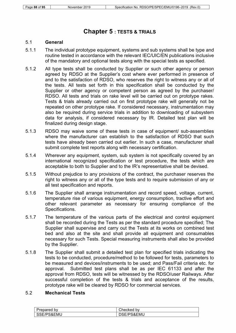
Page 88 of 95 November 2019 Specification No. RDSO/PE/SPEC/EMU/0196–2019 (Rev.0)
Prepared by Checked by SSE/PS&EMU DSE/PS&EMU
Chapter 5 : TESTS & TRIALS
5.1 General 5.1.1 The individual prototype equipment, systems and sub systems shall be type and
routine tested in accordance with the relevant IEC/UIC/EN publications inclusive of the mandatory and optional tests along with the special tests as specified.
5.1.2 All type tests shall be conducted by Supplier or such other agency or person agreed by RDSO at the Supplier’s cost where ever performed in presence of and to the satisfaction of RDSO, who reserves the right to witness any or all of the tests. All tests set forth in this specification shall be conducted by the Supplier or other agency or competent person as agreed by the purchaser/ RDSO. All tests and trials on rake level will be carried out on prototype rakes. Tests & trials already carried out on first prototype rake will generally not be repeated on other prototype rake. If considered necessary, instrumentation may also be required during service trials in addition to downloading of subsystem data for analysis, if considered necessary by IR. Detailed test plan will be finalized during design stage.
5.1.3 RDSO may waive some of these tests in case of equipment/ sub-assemblies where the manufacturer can establish to the satisfaction of RDSO that such tests have already been carried out earlier. In such a case, manufacturer shall submit complete test reports along with necessary certification.
5.1.4 Wherever any equipment, system, sub system is not specifically covered by an international recognized specification or test procedure, the tests which are acceptable to both to Supplier and to the IR’s representative shall be devised.
5.1.5 Without prejudice to any provisions of the contract, the purchaser reserves the right to witness any or all of the type tests and to require submission of any or all test specification and reports.
5.1.6 The Supplier shall arrange instrumentation and record speed, voltage, current, temperature rise of various equipment, energy consumption, tractive effort and other relevant parameter as necessary for ensuring compliance of the Specifications.
5.1.7 The temperature of the various parts of the electrical and control equipment shall be recorded during the Tests as per the standard procedure specified; The Supplier shall supervise and carry out the Tests at its works on combined test bed and also at the site and shall provide all equipment and consumables necessary for such Tests. Special measuring instruments shall also be provided by the Supplier.
5.1.8 The Supplier shall submit a detailed test plan for specified trials indicating the tests to be conducted, procedure/method to be followed for tests, parameters to be measured and devices/instruments to be used; and Pass/Fail criteria etc. for approval. Submitted test plans shall be as per IEC 61133 and after the approval from RDSO, tests will be witnessed by the RDSO/user Railways. After successful completion of the tests & trials and acceptance of the results, prototype rake will be cleared by RDSO for commercial services.
5.2 Mechanical Tests

Page 89 of 95 November 2019 Specification No. RDSO/PE/SPEC/EMU/0196–2019 (Rev.0)
Prepared by Checked by SSE/PS&EMU DSE/PS&EMU
5.2.1 Validation of Designs of Bogie and testing of prototype Bogie including static load and fatigue tests as per relevant standards. Characteristic tests of various suspension items including rubber suspension elements will be submitted. Type testing reports for these suspension elements shall also be submitted.
5.2.2 Oscillation trials (on prototype rake) After commissioning of the rakes fitted with the equipment supplied by the supplier, IR shall conduct oscillation trials on nominated section of IR. The supplier’s representative shall be present in this trial to the extent of any problem related with the equipment under his scope of supply. The oscillation trial shall be conducted as per 3rd (Rev.-01) report of the Standing Criteria Committee of RDSO with revision/amendments as on date of opening of tender. IR also intend to switchover to UIC 518, EN 14363 for testing. Instrumented measuring wheels (4 nos) required for testing as per UIC 518, EN 14363 shall be arranged by the Supplier and may be taken back after the trials.
5.2.3 Braking Distance trial (on prototype rakes) After the completion of satisfactory oscillation trial, the braking distance trials shall be conducted by IR for the rake formation of 16/20/24 Car rake. The rake formation shall be finally decided during design stage. The supplier shall be associated with this test in respect of the items related to regenerative braking, brake blending and connected microprocessor controls.
5.2.4 Tests on Parking brakes (on prototype rake) Parking brakes shall be tested by applying the parking brakes fully and air brake released under the specified conditions as defined in the Clause 4.25.
5.2.5 Coupler force trials (on prototype rake) The measurements shall be recorded in accordance with the test scheme approved by the RDSO in accordance with Good Industry Practice. The Purchase shall submit allowable coupler force in tensile and compressive mode of operation.
5.2.6 Working out actual Train resistance formula for the prototype rake 5.3 Electrical Tests 5.3.1 Generally test procedures shall be followed as per the latest IECs of
Equipment/Systems/Subsystems testing. (i) Along with ‘mandatory’ tests as described in the IECs, ‘optional and
investigative’ tests shall also be conducted. Any other tests which become imperative due to the specific requirement of this specification and is categorically mentioned in this specification shall also be carried out.
(ii) RDSO may waive some of these tests in case of equipment/sub assemblies where the manufacturer can establish to the satisfaction of RDSO that such tests have already been carried out earlier or where the equipment have been proved in service. In such a case, manufacturer shall submit complete test reports along with necessary certification.

Page 90 of 95 November 2019 Specification No. RDSO/PE/SPEC/EMU/0196–2019 (Rev.0)
Prepared by Checked by SSE/PS&EMU DSE/PS&EMU
5.3.2 Witness of tests: Type tests on major electrical equipment like traction transformer, traction motor, traction converter, auxiliary converter, control electronics, Air-conditioning unit, auto door closing system, air supply system and TCMS / TCN shall be witnessed by representative of RDSO. Any new design of equipment offered by the supplier and accepted during the design stage shall also be type tested and witnessed by the representative of RDSO.
5.3.3 Raw material/Component and subsystem testing: RDSO may also in addition, require test results on raw materials and components of critical nature, so as to ensure that they meet the performance and reliability stipulations. This may extend to components/raw materials not manufactured in the manufacturer’s works, but purchased by him. For proven materials, which have been tested before, tests need not be conducted again. Certified test report shall be submitted if so required by RDSO. Subsystems like PIS, TCMS and control equipment etc. shall be supported with tests reports and certificates. However, in case such subsystems are required to meet any special requirement specified herein, the relevant tests shall be carried out by the supplier. The Supplier shall submit a Quality Plan for major items giving the tests conducted on incoming materials, tests done at different stages of manufacture giving “Check Points” to proceed to next stage and tests done on finished product.
5.3.4 Cables: All cables shall be tested against the requirements as laid down in the relevant IEC/UIC/EN specifications. Cables shall also be tested for ensuring its Fire retardant characteristics. Details shall be submitted by the supplier during the design stage.
5.3.5 Traction Motor Tests: Details of the test requirements are as per Clause no. 4.6.
5.3.6 Tests On Control Electronics And PCBs: Control Electronics shall be tested as per IEC 60571/EN50155 IEC 60068, IEC 60721-2-5 and IEC 61373 including both compulsory and optional tests. Following tests shall be carried out on the electronics PCBs as per IEC 60571/EN 50155 and IEC 61373 with the modified parameters. (i) Dry Heat test: Dry Heat test shall be done at 800C. Alongwith the
testing for the satisfactory performance, temperature stickers shall be put on the critical ICs, Controllers & capacitors etc. for monitoring the maximum temperature of these components during dry heat tests. It shall be confirmed that the temperature recorded during dry heat test as above does not exceed the specified operating/surface temperature of these components. For the purpose, data sheets of such components shall be referred and submitted during testing.
(ii) Cyclic Humidity test: The tests shall be done for 2 cycles of 24 hours each and components shall be examined for the performance tests and physical damage if any. The humidity cycle shall be as specified in IEC 60571.

Page 91 of 95 November 2019 Specification No. RDSO/PE/SPEC/EMU/0196–2019 (Rev.0)
Prepared by Checked by SSE/PS&EMU DSE/PS&EMU
(iii) Salt Mist Test: The test duration shall be 48 hours and after the tests the performance test shall be done. There shall be no physical damage, rusting or deterioration of the varnish/lacquer coating.
(iv) Dust & Sand Test & Mould growth test: The tests to determine the performance of the electronics in Sand and Dust ambient shall be carried out with the dust settlement rate of 6gm/m2/day. The dust particle size shall not be larger than 100 µm. Further details shall be worked out at design stage. The reference IEC shall be IEC 68; test Dust and Sand and IEC721-2-5 test Dust and Sand. The component shall be protected against mould/fungal growth. The test scheme shall be finalized during design stage.
5.3.7 Power & Auxiliary converter/Inverter: Tests shall be done as per IEC 61287. 5.3.8 Auxiliary Machine
All auxiliary machines including the motor-compressor set shall be tested in accordance with the relevant IEC specifications. All auxiliary machines not covered in IEC shall be subjected to such tests as decided by RDSO during finalisation stage to ensure that it will meet the working conditions.
5.3.9 Test on HVAC after commissioning on Car (i) Verification of co-efficient of Heat Transfer (Refer clause 4.39.23) (ii) Pre-cooling test (Refer clause 4.39.5) (iii) Pull down test (Refer clause 4.39.5)
5.4 Complete Train: Complete train shall be type & routine tested as per IEC 61133 and as per the test program agreed by RDSO. After erection, the complete equipment shall satisfactorily withstand the dielectric voltages as specified in the IEC specification.
5.5 Sequence Test: Connection shall be made to the 25 kV AC overhead contact system and all parts of the control and main power circuit shall be tested out to ensure correct sequence of operation, all interlock cut-out switches shall then be tested, and the pantograph shall be tested to prove the speed of raising and lowering.
5.6 Interference Test: Tests to determine the levels of interference with traction power supply, signal and telecommunication equipment and facilities to prove that these are within acceptable limits in accordance with the Specification. The Supplier shall provide necessary complete set of calibrated equipment/instrumentation and technical guidance to verify such parameters, which are necessary for evaluation of the Trains.
5.7 Pacemaker Interference Test: 5.7.1 This shall include test to verify that any emissions from the equipment of Train
do not adversely affect the pacemakers/ hearing aids that may be used by the passengers. Test shall be conducted as per EN 45502 and EN 50500.
5.8 Test on Combined Test Bed:

Page 92 of 95 November 2019 Specification No. RDSO/PE/SPEC/EMU/0196–2019 (Rev.0)
Prepared by Checked by SSE/PS&EMU DSE/PS&EMU
5.8.1 Supplier shall furnish details of the test facilities available at their works or at the test laboratory where the system performance tests of the complete equipment is proposed to be carried out as per IEC 61377. Combined system test shall be performed on complete set-up of one basic unit with full compliment of propulsion equipment to assess the efficiency of combined propulsion system & temperature rise with full traction transformer loading.
5.8.2 The supplier shall be responsible to arrange the testing of propulsion equipment on the combined test bed at manufacturer’s works as per the stipulations of IEC 61377. Both the type and investigative tests shall be done at all the specified loads including the full load and special loading conditions with reference to the maximum wheel diameter difference. This shall also include measurement of system efficiency and monitoring of system response in case of failure of control signals.
5.9 Vibration and Shock Values: The equipment used in the cars shall conform to IEC 61373 for shocks and vibrations as specified on the basis of the location and mounting of the equipment. The tests shall also cover Endurance tests included herein.
5.10 Service Tests The prototype rakes fitted with the supplied equipment, shall be subjected to service trials (refer Clause no. 1.8.12). Service trials are intended to prove the satisfactory running performance of the supplied equipment and evaluate their reliability in service, ease of maintenance and operations. The performance of the equipment shall be assessed based on the experience gained during the service trials. Necessary modification as required and also as desired by the RDSO shall be implemented in the series production as well as on the prototype rakes.
5.11 Performance Test (On Prototype Rakes) The Train performance with regard to the supplied equipment shall be demonstrated in test runs and shall meet the target figures given in Chapter 3.
5.11.1 Test Runs: (i) Test runs shall be carried out on nominated sections of IR or any
other sections on which the stock is to be operated with sufficient number of trains to ensure that the train equipment meets the operating conditions. The Supplier shall arrange instrumentation and record speed, voltage, current and temperature rise of various equipment, energy consumption, tractive effort and any other relevant parameter.
(ii) The temperature of the various parts of the electrical equipment shall be recorded during the test as per the standard procedure specified. For further details refer Chapter 3.
(iii) The Supplier shall supervise and carry out the above tests both at his works on combined test bed and also at the site and shall provide all equipment required for such tests and such special consumable stores as oil, grease etc, for the first filling and for trial runs. Special measuring instruments shall be provided by the Supplier.

Page 93 of 95 November 2019 Specification No. RDSO/PE/SPEC/EMU/0196–2019 (Rev.0)
Prepared by Checked by SSE/PS&EMU DSE/PS&EMU
(iv) During the tests acceleration, deceleration, speed on straight level track and the energy consumption for a round trip shall be measured. In all cases, 16-Car fully loaded train shall be tested. However, certain tests viz. TCMS, braking, interference etc. shall be carried out on higher configuration also up to 24-cars.
5.12 Energy Consumption The supplier shall measure the required values of energy saving for a 16-car, fully loaded rake as per Clause no. 3.5.10; operation on the nominated section for all out running without coasting and as per time table halting at halt stations. The following values shall be recorded:
• Traction energy consumption without electrical braking.
• Regenerated energy through electrical braking.
• Energy consumption by auxiliaries 5.12.1 The estimated specific energy consumption figures along with the break up as
mentioned in above para of this clause, will be submitted by the Supplier for each section based on the train resistance formula and track profile & permanent speed restrictions.
5.12.2 The validation of efficiency and energy consumption shall be done on the combined system test bed and at field on the vehicle as per the IEC 61377 and 61133.
5.12.3 Acceleration: The acceleration will be calculated from the time taken to reach a speed of 40 km/h. The time taken shall be from the instant master controller is switched on to the instant speed of 40 Km/h is touched.
5.12.4 Tests will be conducted to confirm acceleration performance according to values specified in Clause 3.2 and jerk performance as per Clause no.3.4.
5.12.5 Deceleration: The deceleration test shall be taken after preliminary runs of the rake in order to bed the brake pads. The test shall be taken on dry rail and the average of three tests will be taken as the final figure for deceleration.
5.13 Installation of Equipment at Purchaser premises: Supplier shall maintain sufficient staff at Purchaser’s works for supervision of installation and commissioning of three-phase propulsion, control and other system and also provide all the necessary support in carrying out these activities. Installation will generally be in the scope of Purchaser, however, is so desired Purchase may entrust this activity to the Supplier. Supplier shall also furnish the installation procedure of all the equipment of three-phase propulsion, control and other system. Supplier shall list the tests to be carried out on the supplied equipment after it has been mounted on the Train at Purchaser’s works or at maintenance depot/workshop of IR or at any other manufacturer’s premises. The test procedure, instrumentation and tolerance shall be furnished. The Supplier shall conduct these tests on two prototypes and all series production of Train sets and also train staff of Purchaser, maintenance shed/workshop/any other manufacturer’s works where the propulsion supplied as per this specification shall be equipped in Train set coaches in carrying out the tests.

Page 94 of 95 November 2019 Specification No. RDSO/PE/SPEC/EMU/0196–2019 (Rev.0)
Prepared by Checked by SSE/PS&EMU DSE/PS&EMU
5.14 Commissioning of Trains at Purchaser’s works and Maintenance depot: Each rake shall be commissioned at Purchaser’s works and maintenance depot / workshop of IR by the Supplier’s staff before putting into commercial service. The Supplier shall be responsible for commissioning of two prototype rakes and all the series production of Train sets. The supplier shall furnish a Commissioning Schedule for the supplied equipment and the system which shall inter-alia include the following:- (i) Confirming satisfactory functioning of the all system. (ii) Test run to confirm specified operating parameters such as
acceleration, deceleration, brake blending and energy consumption etc.
(iii) Rectification / replacement of any malfunctioning equipment. (iv) Check of all the safety related items.
5.15 Test for Air Spring Deflation Detection System: Air spring deflation detection test shall be carried out through reduction in pressure inside the air spring. For this purpose, necessary instrumentation shall be arranged by Supplier.
-------------

Page 95 of 95 November 2019 Specification No. RDSO/PE/SPEC/EMU/0196–2019 (Rev.0)
Prepared by Checked by SSE/PS&EMU DSE/PS&EMU
LIST OF ANNEXURES
S. No. Annexure No. Description Reference clause
1. Annexure-I Design data calculations & drawings to be submitted by Supplier.
1.4.15, 1.11.4
2. Annexure-II Simulation results to be submitted by Supplier
3.5.6
3. Annexure-III List of Standards for testing of equipment
1.11.22
4. Annexure-IV Route profile of HWH-NDLS Section
3.2.7
5. Annexure-V Limits of interference currents
2.12.1, 2.12.6
6. Annexure-VI Tele-communications cabling installation
2.12.4
7. Annexure-VII Time Table of Rajdhani Train
3.2.7
8. Annexure-VIII Bow profile of Panto Pan 4.43.4 9. Annexure-IX List of equipment for which
MTBF/MDBF to be submitted
2.11
10. Annexure-X Car Layout OGA drawings 2.1

November 2019 Annexure I of Specification no. RDSO/PE/SPEC/EMU/0196–2019
Prepared by Checked by SSE/PS&EMU DSE/PS&EMU
Annexure I
DESIGN DATA, CALCULATIONS AND DRAWINGS TO BE SUBMITTED BY THE SUPPLIER
A) Design data should include following particulars: 1. Pantograph: Make and type, working and maximum range, variation of
pressure over working range, rated current capacity, weight, maximum and recommended operating speed, Dimension of mounting insulators, Lock down height, Clearance from roof, weight of the equipment. Overall design parameters vis a vis specification requirements.
2. Vacuum Circuit Breaker: Make and type, rated voltage and current, the
maximum permissible operating voltage, rated short time current, total fault clearing time, making and breaking capacity, impulse voltage withstand, control circuit voltage, number and rating of auxiliary contacts, overall dimensions and weight of the equipment.
3. Transformer: Make and type, type of construction, particulars of
windings with their continuous rating, permissible duty cycle, percentage impedance voltage of each winding with different combinations of windings shorted, no-load magnetisation current, current density in windings, transformer losses and efficiency, permissible temperature rise, details of cooling system, details of insulation of windings, dielectrics levels, overall dimensions and weight particulars of the transformer with and without cooling equipment. Suspension arrangement and calculations. Noise level, procedure for calculation of rating, short time KVA rating, no. of Auxiliary winding, % impedance, type of oil, protection provided, clearance from ground under tare & loading
4. Details of the radiator, relays and other devices/equipment associated
with the transformer. 5. Traction Converter: Make and type, number of cubicles per motor
coach, thermal characteristics of IGBTs, heat sink details of IGBTs, cooling system design details including air/water flow rates and arrangement of filtered air, noise level, IP level, configuration with detail calculation of branch wise current proving adequacy of the devices used, Rating of each IGBT, Thermal margin with calculations.
Details of the capacitor for DC link as well as resonance circuit, if provided, details of the protection of power converter, the designed power loss in the converter. Input/Output voltage, current, power rating (KVA), number of IGBTs, rating and mode of connectivity / configuration (with technical data sheet), number of diodes (with technical data sheet), type of control, switching frequency, noise level, efficiency, number of modules per motor coach, power factor, weight, overall dimensions, DC

November 2019 Annexure I of Specification no. RDSO/PE/SPEC/EMU/0196–2019
Prepared by Checked by SSE/PS&EMU DSE/PS&EMU
bus voltage, no. of motors controlled per inverter, no. and type of harmonic filters, dielectric strength, data sheets for power devices and their characteristic curves, interference currents, details of slip-slide control
6. Train Control & Management System: Details of protocols, Software
modification and interface requirements. Make and type, details of microprocessor, Complete functional description, details of faults to be displayed in driving cab and stored in permanent memory, procedure for down loading the details of faults from memory, details of all protection schemes of all equipment, details of control for converter, DC link, inverter, traction motor, braking etc. Standard followed and details of protocols, details of standard and references, redundancy on basic unit and train level, optimization (minimization) of cable requirement, details of the system, scope of the system offered, no. of signals multiplexed, software logic document, details of software tools, Circuit diagrams.
7. Auxiliary converter: Make and type, number of cubicles per motor
coach, arrangement of devices, margin in junction temperature, cooling system design details including air flow rates and arrangement of filtered air, noise level, protection system, overall dimensions and weight, maximum output current at the time of starting the auxiliaries. Capacity calculation, input voltage / current, no. of phases and output voltages, output voltage/current, THD, power rating (KVA) & its break up, efficiency, type / no. of devices used with rating and data sheet, type of control, switching frequency, type of cooling, type of enclosure, load management in case of reduced auxiliary power.
8. Smoothing Reactor/ Filters: Make and type, number and rating of the
coils, inductance and ripple characteristics up to 1.7 times the rated transformer secondary current, details of the conductor and insulation system, current density, losses, temperature rise limit, details of cooling system, dielectric test voltages, overall dimensions and weight of the equipment.
9. Following design details of Traction motor to be submitted as part of
design document:
Sr. No. Parameters 1. Continuous Rating a. Shaft output(KW b. Nominal Voltage(Phase to phase)(V) c. Current(A) d. Speed(rpm) e. Torque(Nm) f. Supply frequency g. Power factor h. Motor efficiency 2. One hour rating a. Shaft output(KW

November 2019 Annexure I of Specification no. RDSO/PE/SPEC/EMU/0196–2019
Prepared by Checked by SSE/PS&EMU DSE/PS&EMU
b. Nominal Voltage(Phase to phase)(V) c. Current(A) d. Speed(rpm) e. Torque(Nm) f. Supply frequency g. Power factor h. Motor efficiency 3. Short time rating a. Shaft output(KW b. Nominal Voltage(Phase to phase)(V) c. Current(A) d. Speed(rpm) e. Torque(Nm) f. Supply frequency g. Power factor h. Motor efficiency 4. Estimated temperature rise of stator winding at
continuous rating 5. Estimated max. temperature rise of rotor &
Bearings 6. Air flow 7. Ventilation to Watt loss ratio 8. Unventilated rating 9. Details of banding
10. Data for motorette test, fits and clearances adopted
11. Maximum frequency 12. Gear ratio 13. Weight of traction motor a. With coupling and gear box assembly b. Without coupling and box assembly
14. Type of suspension 15. Type of cooling 16. Maximum temperature index of winding insulation 17. Maximum working & test speed in rpm 18. Speed in RPM (wheel dia. New/Half worn/worn
condition) & corresponding vehicle speed in Kmph 19. Type of insulation system adopted 20. Complete Insulation details (used in TM,
specification and thickness) 21. Current density(Stator winding/Rotor
Bar/resistance ring) 22. Current density in stator winding/Rotor bar at max.
starting torque 23. Flux density on rotor teeth & stator teeth 24. Slip at full load ( At Rated Voltage/Minimum
Voltage 25. Power to weight ratio

November 2019 Annexure I of Specification no. RDSO/PE/SPEC/EMU/0196–2019
Prepared by Checked by SSE/PS&EMU DSE/PS&EMU
26. Type of impregnation 27. Type of varnish used for impregnation along with
specification. 28. Lubrication details of TM bearings 29. Equivalent circuit diagram 30. Constructional details viz Rotor bar & rotor end ring
arrangement 31. Overhang to terminal box connection 32. Stator a. Diameter of stator bore b. Length of stator core c. Material and specification for stator core stamping d. Material and specification for resistance ring e. Rating of stamping(Watt loss per Kg) f. No. of Stator slot g. Air gap h. Slot size I. Resistance per phase at 20°C j. Reactance per phase at base frequency k. Type of Winding l. No. of conductors/slot
m. No. of coils used n. No. of turn per coil o. Stator coil slot pitch p. Pitch factor q. Distribution factor r. Winding factor s. Conductor size (bare) t. Conductor size (covered) & Insulation details
33. Rotor a. Material and specification for rotor core stamping b. Rotor diameter c. Rotor length d. Rating of stamping(Watt loss per Kg) e. No of rotor slots and its size f. Dimension of rotor bar g. Material and specification for rotor bar h. Material and specification for resistance ring
34. FE analysis(with boundary conditions finalized in consultation with RDSO)
a. FE calculation & analysis of Rotor b. FE calculation & analysis of Shaft c. FE analysis of stator frame d. FE calculation and analysis of Motor
35. L10 calculation for drive & non drive end of TM 36. Complete Bill of material along with material
specification & source

November 2019 Annexure I of Specification no. RDSO/PE/SPEC/EMU/0196–2019
Prepared by Checked by SSE/PS&EMU DSE/PS&EMU
37. Lubricating cycles 38 Fits and clearances adopted
10. Gear box assembly: Make and type, grade of steel used, particulars of
heat treatment, material and type of construction of gear box, make & type of lubrication compound of gear box.
11. Auxiliary Machines & Blowers: Make and type of various auxiliary
machines, nominal voltage, starting current and torque, torque speed characteristics at various voltages, continuous rating, efficiency, speed, power factor and slip of the motor, type of enclosure, details of cooling fan, air gap, details of windings and insulation, conductor size, current density, type of conductor insulation, details of impregnation, details of lead wire, terminals and terminals block, material of core stampings and average flux density, details of rotor end rings and bars with current density, details of bearing giving sizes, clearances, tolerances, dimensions, L-10 life calculation of the bearings and weight of machines, tests conducted to ascertain the reliability of windings/motors. Make and type of the blower units, power consumption at rated capacity, dimensions and weight of the blower.
12. Contactors / MCB: Make and type, rated voltage and current, making
and breaking capacity, number of auxiliary contacts with control circuits voltage, magnet valve and coil details, overall dimensions and weight, mechanical and electrical endurance test data.
13. Lightning Arrestor: Make and type, rated voltage, dry and wet power
frequency withstand voltage, minimum power frequency spark over voltage, nominal discharge current, impulse spark over voltage, overall dimensions and weight.
14. Master and Brake Controller: Make and type, rated current, making
and breaking current, positions of reverser and main handle and auxiliary interlocks, overall dimensions and weight, details of redundancy, mechanical and electrical endurance test data.
15. Relays: Make and type of various relays, rated current and voltage,
range of setting, rated control voltage, rating of contacts, details of material of the contact, type of enclosure, temperature rise limit, indication system provided, overall dimensions and weight, mechanical and electrical endurance test data.
16. Compressor: Make, type and model, number of stages, rated speed,
maximum pressure, graph showing FAD against 8, 9 and 10 kg/cm² pressures, maximum permissible temperature at inlet and exhaust ports, details of drive arrangement and coupling, lubrication requirements, overall dimensions and weight, Type of motor, KW rating, Voltage, Rated current, Insulation class, Efficiency, Mounting, Capacity of

November 2019 Annexure I of Specification no. RDSO/PE/SPEC/EMU/0196–2019
Prepared by Checked by SSE/PS&EMU DSE/PS&EMU
compressor in lit / min, Noise level at 4.6 m, air intake / filter system, type of lubrication.
17. Battery Charger: Make and type of the battery charger, capacity and rating, ripple content, load regulation, dimensions and weight, charging method and its characteristics.
18. Isolating and Programme Switches: Make and type, rated voltage and
current, short time current, description and details of interlocking arrangement, number of auxiliary contacts, overall dimensions and weight, mechanical and electrical endurance test data
19. Auxiliary Compressor: Make and type, capacity and pressure, speed,
motor rating and working voltage, overall dimensions and weight.
20. Regenerative Brake Blending: Make and type, functional description of complete system and individual components, operating pressure, overall dimensions and weight.
21. Control Electronics And Displays: Details of control electronics,
PCBs, Redundancy adopted at various levels, Protection level against dust, moisture, corrosion and salty atmosphere, Types of display, protection level against dust, moisture, vandalism and comparative advantages, Devices for ‘Log In’ journey details, Weight of Displays, Overall dimensions and features of Displays
22. Passenger Information And Communication System: Details of
scheme and protocol, No. of amplifiers and speakers, expendability, provisions / facilities, Priorities incorporated, Experience of the system offered, Number of displays per coach, Type of display LED/LCD, Display of dynamic route map and advertisement videos, Weight & size of displays
23. Cables: Power, control and communication cables, Source,
Specifications, Properties
24. Inter vehicular couplers (combined electrical – mechanical couplers): Details of design parameters, Protection against water ingression due to flooding conditions in Mumbai, No. of spare contacts, Weight, Overall dimensions, layout, protection against vandalism
25. Air-conditioning system design: functional description along with
equipment/system, including controls; cooling capacity curve, cooling capacity versus power curve of the compressor along with the comparison with standard curves; complete heat load calculation and air conditioning system capacity to achieve maximum possible Energy Efficiency Ratio.

November 2019 Annexure I of Specification no. RDSO/PE/SPEC/EMU/0196–2019
Prepared by Checked by SSE/PS&EMU DSE/PS&EMU
B) Design Calculations should include:- 1. Weights and centre gravity of each equipment together with weight
unbalance calculations etc.
2. Adhesion calculation.
3. System performance calculations.
4. Gears box, analysis of stresses, selection of bearing, gear box and transmission assembly.
5. Calculations for lateral and longitudinal equipment balancing.
6. EP brake system, brake effort calculations. 7. Braking distance calculations under gross load condition at maximum
permissible operating speed at level track.
8. Cooling system calculations.
9. Tractive and braking effort vs speed curves showing balancing speed.
10. Detailed step-wise calculations for equipment ratings and performance requirement.
11. Curves of efficiency, power factor, frequency, slip as a function of speed.
12. Traction Motor performance curves.
13. Calculations for life of bearings used in Traction Motors and aux.
machines.
14. Harmonic calculations.
15. Calculation of shaft strength for Traction and aux. Machines, calculation of moment of inertia, shaft strength etc.
16. Reliability predictions.
17. Acceleration, deceleration and jerk control
18. Thermal simulation of propulsion equipment as per the requirements of specification
19. Time and distance to achieve maximum service speed with normal and
one basic unit isolation
20. Traction converter control and switching pattern

November 2019 Annexure I of Specification no. RDSO/PE/SPEC/EMU/0196–2019
Prepared by Checked by SSE/PS&EMU DSE/PS&EMU
C) Following drawings to be submitted as part of design document including dimensions and material specifications: 1. Layout drawing for roof, underfloor, driving cab, motor and trailer
coaches.
2. Schematic diagram of power, dynamic braking, control and auxiliary circuits including multiple operation.
3. Tractive effort transmission diagram.
4. Brake system diagram.
5. Drawing showing mounting arrangement of traction motor.
6. Motor suspension arrangement.
7. Drawings of Traction motor and drive:
S.No. Description 1. Traction Motor outline assembly 2. Longitudinal section 3. Cross-section 4. Stator housing machined 5. Wound stator assembly 6. Detail of Stator Winding Overhang Support 7. Stator coil 8. Stator slot cross section showing Insulation details along
with thickness & specification 9. Stator & rotor punching 10. Winding diagram 11. End shield DE 12. End shield NDE 13. Bearing assembly arrangement DE 14. Drawings of individual bearing assembly components (DE) 15. Bearing assembly arrangement NDE 16. Drawings of individual bearing assembly
components(NDE) 17. Terminal box assy. 18. Stator End punching 19. Rotor End punching 20. Wedge 21. Stator winding support arrangement 22. Rotor Assembly 23. Shrink ring 24. Rotor End Ring DE & NDE 25. shaft machined 26. rotor bar 27. Resistance ring machined 28. ventilator

November 2019 Annexure I of Specification no. RDSO/PE/SPEC/EMU/0196–2019
Prepared by Checked by SSE/PS&EMU DSE/PS&EMU
29. Mounting arrangement of TM 30. Motor suspension arrangement 31. Traction motor cooling duct arrangement 32. Air inlet arrangement 33. Air out let arrangement 34. Motor terminal box
8. Drawings for pantograph, pan and strips.
9. Auxiliary machines drawing giving longitudinal and cross section details
of stator winding, motor construction etc.
10. Mounting details of major equipment.
11. General arrangement of transformer, winding, core and auxiliaries, if any.
12. General arrangement of circuit breaker, earthing switches, isolators,
contactors, relays etc.
13. Master controller drawing showing driving controls, cam contacts and pneumatic and mechanical connections.
14. Transformer and power converter cooling arrangement.
15. General arrangement for wheel slip detection and correction system.
16. Detailed drawings of the Bogie assembly for all type of coaches.
17. Air-conditioning arrangement. Note: The items as above are indicative only. Supplier is advised to refer the
relevant clauses of the specifications for submitting the details required.

November 2019 Annexure II of Specification no. RDSO/PE/SPEC/EMU/0196–2019
Prepared by Checked by SSE/PS&EMU DSE/PS&EMU
Annexure II PERFORMANCE SIMULATIONS TO BE SUBMITTED BY THE SUPPLIER a) REF. CLAUSE 3.1.3 & 3.5.2
1. Conditions:-
i) 16 car loaded rake ii) Line Voltage 22.5 kV AC ii) All out run (with dwell time of 30 sec) iii) Maximum possible regeneration with full service brake iv) Gross weight of Train : 550 t plus weight of the equipment (all items
mentioned in clause no. 4.1 to be considered) to be supplied by Supplier for 16 Car Train
2. Simulations a) Tabulation:-
Section Run time RMS current of traction motor
Line current peak
10 km section on level tangent track
b) Graphical values
i) Time vs. Speed, Distance, Motor current, Line current, TE, BE, TR, acceleration/deceleration
ii) Distance vs. Speed, time, Motor current, Line current, TE, BE, TR, acceleration/deceleration
c) Temperature rise of propulsion equipment with graphical presentation till
stabilization.
b) REF. CLAUSE 3.5.3 and Chapter 3 1. Conditions:-
i) 16 car loaded rake ii) Line Voltage 22.5 kV AC ii) All out run (with dwell time of 30 sec) iii) Maximum possible regeneration with full service brake iv) Gross weight of Train : 550 t plus weight of the equipment (all items
mentioned in clause no. 4.1 to be considered) to be supplied by Supplier for 16 Car Train
2. Simulations a) Tabulation:-
Section Time Distance Line current
Consumed
energy
Regenerated energy
% Regen
Time & distance to achieve speed of 160kmph (normal rake)
N.A. N.A.

November 2019 Annexure II of Specification no. RDSO/PE/SPEC/EMU/0196–2019
Prepared by Checked by SSE/PS&EMU DSE/PS&EMU
Time & distance to achieve speed of 160kmph (one basic unit isolated)
N.A. N.A.
Time to complete one cycle of 10 km (with normal rake)
Time to complete one cycle of 10 km (one basic unit isolated)
c) Graphical values
i) Time vs. Speed, Distance, Motor current, Line current, TE, BE, TR,
acceleration/deceleration ii) Distance vs. Speed, time, Motor current, Line current, TE, BE, TR,
acceleration/deceleration iii) Compliance of clause no. 3.4.3
c) REF. CLAUSE 3.5.6
1. Conditions:
i) 16 car loaded rake with one basic unit isolated conditions ii) 22.5 kV AC iii) All out run (with stop time)
2. Simulations:-
Section Run time RMS current of traction motor
Line current peak
10 km section of 1 in 37 3. Graphical values
i) Time vs. Speed, Distance, Motor current, Line current, TE, BE, TR,
acceleration/deceleration ii) Distance vs. Speed, time, Motor current, Line current, TE, BE, TR,
acceleration/deceleration iii) Temperature rise of propulsion equipment with graphical presentation.
d) REF. CLAUSE 3.2.7 :
1. Conditions:
i) 16 car loaded rake ii) 22.5 kV AC & 21.5kV AC iii) Train operation in allout mode with dwell time as mentioned in annexure VII iv) Route profile as per annexure IV v) Section : HWH-NDLS & NDLS-HWH vi) Full auxiliary load
2. Simulations:-
Distance Time Speed Speed restriction
TE/BE
OHE Current
Instant Energy
Cummulative energy
Cummulative energy

November 2019 Annexure II of Specification no. RDSO/PE/SPEC/EMU/0196–2019
Prepared by Checked by SSE/PS&EMU DSE/PS&EMU
/ Station haults
consumed consumed in traction
consumed in braking
3. Graphical values
i) Time vs. Speed, Distance, Motor current, Line current, TE, BE, TR, acceleration/deceleration
ii) Distance vs. Speed, time, Motor current, Line current, TE, BE, TR, acceleration/deceleration
iii) Results mentioned in above table should be submitted for each 25m or 1sec sampling rate
e) CHARACTERISTICS AND EFFICIENCY CURVES 1. Performance curves for Motoring and regenerating. 2. Conditions
i) 22.5 kV AC and 27.5kV Wheel dia new, half worn wheel, worn wheel
Parameters to be included in the curve Speed Vs Tractive effort / Braking effort, Train resistance, Line current, Traction
Motor voltage, Traction motor current, Traction motor power factor, Motor frequency, slip frequency, Balancing speed.
f) EFFICIENCY CURVES FOR MOTORING AND BRAKING
1. Conditions:
i) 22.5 kV AC and 27.5kV Including following Speed Vs. Gear efficiency, Inverter Efficiency, Converter efficiency, Transformer efficiency, Traction Motor efficiency, Overall system efficiency.
g) TRACTION MOTOR CHARACTERISTICS AS PER IEC 60349-2
h) CLAUSE 2.12– SIMULATION OF LIKELY VALUES OF HARMONIC
CURRENTS. IMPORTANT: The listed requirements as above are indicative, Supplier is advised to refer
the main clauses of the Specification.

November 2019 Annexure III of Specification no. RDSO/PE/SPEC/EMU/0196–2019
Prepared by Checked by SSE/PS&EMU DSE/PS&EMU
ANNEXURE – III
LIST OF STANDARDS FOR TESTING OF EQUIPMENTS
All the equipment shall be type and routine tested with the relevant specification. Supplier shall conduct all type and routine tests of all clauses of latest RDSO/IEC/BS/DIN/JIS/IS or latest equivalent specification whichever is applicable, including optional tests. Detailed test programme shall be furnished by the Supplier and approved by RDSO before undertaking the type tests.
1. Electric traction – rolling stock – test methods for electric and thermal /electric rolling stock on completion of construction and before entry into service
IEC 61133
2. Electronic equipment used on rail vehicles IEC-61287
3. Specific rules concerning the electronic control part of converters
IEC-60571
4. Electric traction - Electronic converter-fed alternating current motors
IEC 60349
5. Railway application – rolling stock – Part 1: combined testing of inverter fed alternative current motors and their control system
IEC 61377
6. Guide for the evaluation and identification of insulation systems of electrical equipment
IEC 60505
7. Electric railway equipment-train communication network
IEC 61375
8. Rotating electrical machines: Functional evaluation of insulation systems
IEC 60034-18
9. Railway applications – electromagnetic compatibility – Part 3-2: rolling stock – Apparatus
EN 50121-3-2 / IEC 62236-3-2
10. Railway applications – electromagnetic compatibility – Part 2: emission of the whole railway system to the outside world
EN 50121-2/ IEC 62236-2
11. Railway applications – electromagnetic compatibility – Part 3-1: Rolling stock – Train
IEC 62236-3-1 / EN 50121-3-1

November 2019 Annexure III of Specification no. RDSO/PE/SPEC/EMU/0196–2019
Prepared by Checked by SSE/PS&EMU DSE/PS&EMU
and complete vehicle
12. Railway applications – compatibility between rolling stock and train detection system
EN 50238
13. Transformer and chokes IEC 60310
14. High voltage AC circuit breaker IEC 60077-4
15. Rules for pantograph of electric rolling stock IEC: 60494-1
16. Relays, contactors and switches IS 3231, IEC 60947
17. Cables IEC 60228, IS 10810, EN 50264
18. Lightning arrestor IEC 60099-4, IS 3070 Pt III
19. Railway applications – rolling stock equipment – shock and vibration test
IEC 61373
20. Programming languages for PLC IEC 61131
21. Railway applications – electric equipment for rolling stock
IEC 60077
22. Electronic equipment used on rail vehicles IEC 60571
23. Power converter installed on board rolling stock – Part 1: Characteristics and test methods
IEC 61287-1
24. Power converter installed on board rolling stock– Part 2: Additional technical information
IEC 61287-2
25. Railway application – rolling stock protective provisions against electrical hazards
IEC 61991
26. Auxiliary machines IEC 60034
27. Power factor correction IEC 60871
28. Environmental testing IEC 60068
29. Battery Relevant IECs
30. Degree of protection provided by enclosures IEC 60529
31. Rules for installation of cabling EN 50343

November 2019 Annexure III of Specification no. RDSO/PE/SPEC/EMU/0196–2019
Prepared by Checked by SSE/PS&EMU DSE/PS&EMU
32. Railway applications, welding of railway vehicles and components. Inspection, testing and documentation.
EN15085
33. Schedule of Dimension for broad gauge IR Schedule Of Dimension for Broad Gauge, revision 2004 with latest amendment
34. Reliability of electronic component IEC 61709
35. RAMS EN 50126/ IEC 62278
36. Metallized carbon strip for pantograph
RDSO’s specification no. RDSO/2009/EL/SPEC/0097 Rev. 1 or latest
37. Lighting arrestor IEC 60099
38. Capacitors IEC 61881
39. Railway applications: Fire protection on Railway vehicles
EN45545
40. Railway applications: Body side entrance systems for rolling stock
EN 14752
41. Railway applications: Air conditioning for urban and suburban rolling stock. Comfort parameters
EN 14750

November 2019 Annexure IV of Specification no. RDSO/PE/SPEC/EMU/0196–2019
Prepared by Checked by SSE/PS&EMU DSE/PS&EMU
ANNEXURE – IV
Speed Restrictions of HWH-NDLS Section
Start km End km Speed Restriction 0 0.8 10
0.8 1.4 15 2.8 2.85 65 3 4.3 100
4.3 4.5 75 4.5 4.9 65 4.9 7.8 100 7.8 8.6 90 8.6 9.8 110 12 13.2 120
15.2 15.6 100 25.6 25.7 100
41.05 43.15 100 43.15 44.5 75 44.6 46 100
47.25 48 100 48.8 50.1 75 50.1 51.2 50 51.4 52.4 110 54.5 54.8 30 94.4 104.35 120
104.35 104.7 90 104.7 105.9 120 105.9 106.45 65 106.5 108.6 120
182.75 182.9 50 194.1 195.7 100
210.35 210.65 100 211.9 212.8 30 218.1 218.2 50
220.65 220.9 30 228.5 228.8 75 228.8 231.4 100
236.95 237.4 100 240.1 240.3 30 253.9 255.5 110 255.7 255.9 20 255.9 256.07 120
260.54 260.66 85

November 2019 Annexure IV of Specification no. RDSO/PE/SPEC/EMU/0196–2019
Prepared by Checked by SSE/PS&EMU DSE/PS&EMU
261.78 261.9 65 261.9 264.78 120
270.12 270.36 80 270.54 271.48 30 290.78 291.36 110
299 299.84 15 316.12 317.12 120 317.12 317.84 110 327.66 328.18 100 331.66 332.6 120 333.18 334.6 100 334.6 334.66 30
339.72 340.24 120 342.72 344.6 120 344.6 346.06 100
364.24 364.3 30 393.3 393.36 100
398.66 399.48 120 403.45 405.6 100 405.6 406.6 80 406.6 407.48 70
407.48 408.48 80 408.48 409 65
409 410.78 80 410.78 410.84 20 414.9 414.96 45
414.96 422.2 80 422.2 425.54 55
455.66 456.06 75 460.12 461.12 75 461.12 461.3 45 461.3 461.42 30 463 464 90
466.12 466.66 80 467.99 469.06 60 469.06 470.99 30 477.06 477.72 100 534.18 534.78 30 549.06 549.94 90 549.94 553.48 50 554.3 554.36 30
565.66 565.72 30 657.78 657.84 30 666.42 666.84 120 668.06 669.99 80

November 2019 Annexure IV of Specification no. RDSO/PE/SPEC/EMU/0196–2019
Prepared by Checked by SSE/PS&EMU DSE/PS&EMU
673.34 673.99 10 683.6 684.7 30 684.7 685.7 75
692.55 692.65 30 701.7 702.12 100 704.2 705.7 100
725.86 725.93 50 740.25 740.5 30 742.7 743.9 100 749.4 754.2 100
815.85 815.9 45 815.9 815.95 20 824.1 824.8 60 826.1 827.3 75 828.2 829.2 75 858.5 859.5 50 966.2 966.3 30
1015.6 1016.3 40 1016.3 1018.95 50
1018.95 1018.97 30 1019.1 1019.24 15 1021.5 1021.57 50
1028.36 1028.41 30 1125.8 1125.87 20 1156.7 1156.91 110 1198.1 1198.8 30 1222.6 1222.9 120
1241.65 1242.2 75 1242.2 1243.1 40 1247.8 1247.9 15
1248.15 1248.95 30 1248.95 1250.65 65 1326.15 1326.35 100 1398.8 1398.9 20
1431.35 1434.75 100 1435 1435.1 45
1440.1 1440.5 70 1455.1 1456.1 70 1456.1 1459 15
Note: The speed restrictions highlighted in the above table indicate Temporary Speed Restrictions and the remaining are the Permanent Speed Restrictions.

November 2019 Annexure IV of Specification no. RDSO/PE/SPEC/EMU/0196–2019
Prepared by Checked by SSE/PS&EMU DSE/PS&EMU
Curves of HWH-NDLS Section
From (km) To (km) Curve in degree 0.300 0.370 5.7 0.560 0.720 4.3 1.850 2.950 3.2 2.950 2.966 1.75 3.533 3.866 0.75 4.070 4.532 1 4.532 5.933 1.5 6.220 6.911 1.05 7.966 9.866 2.33 12.070 13.350 2.1 16.333 16.933 1 20.899 21.667 0.5 30.575 31.200 0.5 36.320 36.840 0.4 49.933 50.300 0.62 56.050 56.800 1.08 58.300 58.800 1.14 61.320 61.960 1.25 68.466 68.866 0.63 72.514 72.857 0.91 79.160 81.129 1.08 93.799 94.199 0.56 94.325 94.900 1.26 94.900 95.160 1 95.260 95.800 1 99.525 99.925 0.73 99.933 100.266 1.09
100.266 103.993 0.39 104.199 104.399 1.75 104.533 104.799 1 105.050 106.600 0.5 108.500 110.900 0.38 118.133 119.800 0.38 128.300 129.050 0.5 129.400 129.700 0.5 129.900 130.300 0.5 130.550 130.700 0.5 132.100 133.200 0.5 138.300 139.400 0.5 144.950 145.500 0.5 152.150 154.400 0.5 160.900 161.650 0.5

November 2019 Annexure IV of Specification no. RDSO/PE/SPEC/EMU/0196–2019
Prepared by Checked by SSE/PS&EMU DSE/PS&EMU
163.550 164.400 0.74 166.250 167.300 1.1 175.900 176.830 0.56 182.900 183.300 1.5 191.030 191.400 0.5 194.030 195.210 1.5 196.150 197.950 1 199.200 199.800 0.75 202.900 203.800 1 204.450 205.050 1.25 208.350 209.800 0.75 210.200 210.600 1 210.850 211.500 0.5 259.05 259.900 0.57 260.24 260.84 1.48 260.84 261.02 0.72 261.84 262.72 2.08 263.02 263.84 2.03 264.54 265.72 0.55 267.6 268.48 1.04 269.24 269.48 1.04 269.66 269.96 2.15 270.12 270.42 2.18 270.48 270.9 1.65 271.23 272.02 1.73 278.6 279.42 1 284.3 284.78 1 286.06 286.78 1 288.3 289.12 1 290.78 291.66 1 294.36 294.9 1 295.78 296.54 1 301.08 302.08 1 303.42 303.66 0.75 305.12 305.72 1 307.72 308.66 1 311.78 312.24 1 314.12 314.6 1.06 316.12 317.26 2.03 317.26 317.96 1.5 320.03 320.42 1 321.66 322.96 1.5 323.24 324.42 1 327.6 328.18 2.06 328.24 328.9 1.5

November 2019 Annexure IV of Specification no. RDSO/PE/SPEC/EMU/0196–2019
Prepared by Checked by SSE/PS&EMU DSE/PS&EMU
329.78 330.6 1.5 331.66 332.6 2.15 333.18 333.96 2.18 333.96 335.54 1.75 336.18 336.96 1.25 339.72 340.24 2.18 342.72 343.84 2 344.6 346.03 2 348.03 348.48 1.09 352.36 352.9 1.55 353.6 354.54 1.05 354.66 355.3 1.29 357.6 358.24 1.06 361.54 362.24 1 363.24 364.03 1.03 364.66 365.48 1.01 369.24 369.78 0.995 374.12 374.6 1 376.66 377.48 0.56 380.6 381.72 1 384.54 385.72 1.02 387.03 388.3 1 390.12 391.12 1.03 394.84 396.12 1.05 397.72 398.12 1.05 398.66 399.48 2.06 400.3 401.72 1.03 401.72 402.18 1.01 405.6 406.03 2.25 406.6 407.48 3.09 407.66 408.66 3.09 410.54 411.48 3.78 411.6 412.08 2.06 412.6 412.9 2.05 412.96 414.38 3.08 414.38 415.12 3.08 415.12 416.66 3.62 416.72 417.03 3.08 417.18 417.84 3.08 418.3 418.66 2.06 419.12 419.72 2.05 419.72 420.42 2.05 420.48 421.3 1.03 421.42 422.12 2.06 424.72 425.03 1.05

November 2019 Annexure IV of Specification no. RDSO/PE/SPEC/EMU/0196–2019
Prepared by Checked by SSE/PS&EMU DSE/PS&EMU
433.66 434.42 1.05 455.72 456.24 0.47 457.12 457.48 0.6 458.36 459.78 1.02
463.00 464.18 3 466.12 466.66 2 467.54 467.99 2.5 468.18 469.48 4.75 469.96 470.99 4.75 472.48 472.99 1 477.54 478.06 0.5 478.42 479.06 0.5 482.06 482.66 0.5 493.30 493.66 0.5 505.12 506.30 0.5 510.06 510.72 1 524.42 524.72 0.5 545.24 546.72 0.75 556.06 556.78 1.12 564.66 565.06 0.63 565.72 567.18 0.7 570.36 571.36 0.7 571.48 571.66 0.42 571.72 571.96 0.42 573.12 573.54 0.45 573.72 576.24 0.56 581.48 581.78 0.32 594.36 594.72 0.5 599.30 599.54 1 600.42 600.66 0.5 621.30 621.90 1 629.66 630.30 1 631.42 632.36 1 643.42 643.72 1.25 646.12 646.42 1 649.84 650.30 1 651.48 651.66 0.5 659.66 660.06 1.25 666.42 667.66 2 668.60 670.72 0.35
692.498 695.11 0.21 701.2 701.94 0.56 702.15 704 0.56
704.075 704.219 0.28 704.451 704.64 0.28

November 2019 Annexure IV of Specification no. RDSO/PE/SPEC/EMU/0196–2019
Prepared by Checked by SSE/PS&EMU DSE/PS&EMU
704.84 704.94 0.50 705.29 705.41 0.56 712.17 713.83 0.60 718.99 719.42 1 719.53 719.92 0.96 733.5 734.8 0.53 735 735.15 0.86
735.15 735.34 0.76 736.05 736.17 3.98 742.62 742.9 0.5
743 743.24 0.58 743.47 743.56 0.53 743.91 745.06 0.44 749.35 751.27 1.16 751.3 754.04 0.46 767.48 769.23 0.5 777.95 778.16 0.89 778.22 778.41 1.20 778.99 779.23 0.84 779.23 779.41 0.94 786.37 786.61 0.5 786.83 787.07 0.5 787.29 787.55 0.38 787.69 787.93 0.5 791.27 792.27 0.5 792.8 794.44 0.5 806.3 807.32 0.875 815.97 816.64 1.05 820.57 820.99 0.20 822.02 822.26 0.40 823.04 824.46 1.25 826.27 827.21 2 828.18 829.16 1.20 829.3 829.61 0.51 829.72 830.03 0.7 833.16 833.57 0.56
835.068 835.248 0.43 835.248 835.448 0.45 837.044 839.125 0.40 842.5 842.68 0.36 842.68 842.86 0.36 842.93 843.127 0.36
843.189 843.309 0.36 861.621 861.791 0.38 861.791 862.033 0.40

November 2019 Annexure IV of Specification no. RDSO/PE/SPEC/EMU/0196–2019
Prepared by Checked by SSE/PS&EMU DSE/PS&EMU
862.651 862.811 0.85 862.811 863.064 0.85 863.132 863.272 0.75 863.441 863.681 0.50 881.554 881.78 0.50 882.01 882.26 0.43 882.35 882.586 0.50 882.93 883.207 0.40
894.207 894.35 0.39 894.43 894.56 0.46 894.73 894.89 0.60 895.95 896.12 0.48
906.343 906.347 0.45 906.347 907.52 0.38 907.76 907.9 0.80 908.29 908.56 0.30 930.1 930.22 0.46 930.26 930.45 0.63 931.46 931.61 0.60 931.63 931.8 0.63 940.99 941.19 0.74 941.82 942.12 0.32 942.32 942.64 0.32 943.12 943.34 0.56 943.34 944.7 0.42 957.45 957.61 0.455 957.65 957.85 0.49 958.9 959.03 0.68 959.1 959.31 0.42 972 972.72 0.35
973.192 973.442 0.50 973.57 973.8 0.50
974.372 974.602 0.50 981.23 982.34 0.60
983.217 983.427 0.24 983.538 983.828 0.53 984.214 984.394 0.53 984.626 986.516 0.42 986.828 987.828 0.42 996.038 996.258 0.51 996.298 996.438 0.28 997.623 997.793 0.39 997.823 998.023 0.45
1001.347 1003.473 0.42 1015.043 1015.203 0.63

November 2019 Annexure IV of Specification no. RDSO/PE/SPEC/EMU/0196–2019
Prepared by Checked by SSE/PS&EMU DSE/PS&EMU
1015.223 1015.363 0.53 1015.784 1016.462 2 1016.632 1017.372 2 1017.652 1019.164 4 1027.63 1027.79 0.24
1027.960 1028.090 0.26 1029.110 1029.320 0.28 1029.440 1029.600 0.3 1037.750 1038.04 0.5 1038.220 1038.5 0.49 1038.55 1038.83 0.56
1038.910 1039.210 0.56 1062.400 1064.310 0.42 1079.618 1079.818 0.08 1079.87 1080.05 0.17
1081.121 1081.311 0.08 1081.391 1081.521 0.17 1098.854 1099.114 0.5 1099.164 1099.554 0.5 1116.344 1116.454 0.1 1116.525 1116.695 0.1 1118.008 1118.158 0.1 1118.278 1118.458 0.1 1123.145 1125.25 0.25 1135.88 1136.3 0.1 1137.01 1137.44 0.1
1152 1152.33 0.1 1154.576 1156 0.617 1156.463 1156.75 0.5 1157.883 1158.31 0.28 1166.15 1166.39 0.1 1166.52 1166.76 0.1 1172.23 1172.49 0.2 1173.45 1173.93 0.2 1179.49 1180.08 0.2 1181.26 1181.63 0.2 1181.84 1182.18 0.2 1191.42 1191.83 0.25 1192.7 1193.13 0.25 1210.4 1211.64 0.5
1211.67 1211.97 0.75 1212.6 1213.02 0.25
1220.95 1221.26 0.487 1221.56 1221.63 0.75 1222.13 1222.4 0.595

November 2019 Annexure IV of Specification no. RDSO/PE/SPEC/EMU/0196–2019
Prepared by Checked by SSE/PS&EMU DSE/PS&EMU
1222.61 1222.85 0.507 1228.87 1229.54 0.253 1229.89 1230.05 0.175 1231.11 1231.23 0.175 1231.23 1231.37 0.175 1232.97 1233.19 0.21 1233.22 1233.44 0.175 1240.77 1240.97 0.253 1240.97 1241.15 0.245 1241.2 1241.49 0.253
1241.54 1241.74 0.253 1246.47 1246.62 1.75 1246.81 1246.94 1.75 1247.99 1248.12 1.75 1248.12 1248.23 1.75 1249.02 1250.31 0.53 1250.63 1250.91 1.2 1250.91 1251.15 0.4 1251.26 1251.56 1.15 1251.63 1252.369 0.52 1254.27 1254.48 0.5 1254.48 1254.68 0.5
1255.842 1256.252 0.5 1262.127 1262.507 0.52 1263.16 1263.53 0.75
1275.362 1275.712 0.53 1276.895 1277.27 0.52 1304.198 1304.568 0.42 1305.789 1306.189 0.42 1322.048 1322.908 0.35 1325.37 1325.48 0.35 1325.5 1325.61 0.35
1325.85 1326 0.35 1326.13 1326.29 0.4 1328.98 1329.14 0.5 1329.2 1329.38 0.5
1334.805 1335.375 0.35 1347.462 1347.762 0.35 1347.957 1348.187 0.5 1348.600 1348.830 0.5 1348.95 1349.28 0.4 1374.92 1375.1 0.4 1375.12 1375.33 0.5 1375.9 1376.06 0.4
1376.08 1376.26 0.4
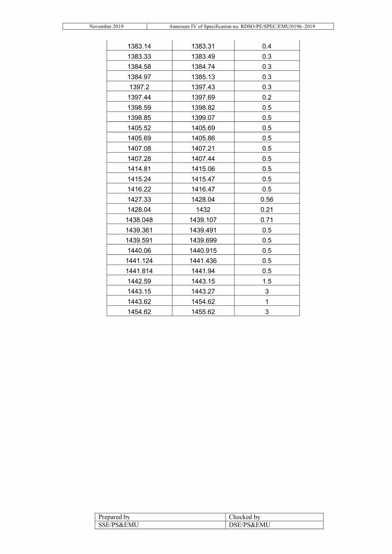
November 2019 Annexure IV of Specification no. RDSO/PE/SPEC/EMU/0196–2019
Prepared by Checked by SSE/PS&EMU DSE/PS&EMU
1383.14 1383.31 0.4 1383.33 1383.49 0.3 1384.58 1384.74 0.3 1384.97 1385.13 0.3 1397.2 1397.43 0.3
1397.44 1397.69 0.2 1398.59 1398.82 0.5 1398.85 1399.07 0.5 1405.52 1405.69 0.5 1405.69 1405.86 0.5 1407.08 1407.21 0.5 1407.28 1407.44 0.5 1414.81 1415.06 0.5 1415.24 1415.47 0.5 1416.22 1416.47 0.5 1427.33 1428.04 0.56 1428.04 1432 0.21
1438.048 1439.107 0.71 1439.361 1439.491 0.5 1439.591 1439.699 0.5 1440.06 1440.915 0.5
1441.124 1441.436 0.5 1441.814 1441.94 0.5 1442.59 1443.15 1.5 1443.15 1443.27 3 1443.62 1454.62 1 1454.62 1455.62 3

November 2019 Annexure IV of Specification no. RDSO/PE/SPEC/EMU/0196–2019
Prepared by Checked by SSE/PS&EMU DSE/PS&EMU
Gradient Details of HWH-NDLS Section
START KM END KM UP/DN/L (1/-1/0)
GRADIENT (e.g. 500 means,
gradient of 1 meter in a distance of
500 meter) 0.00 21.40 0.00 0.00
21.40 22.50 -1.00 1000.00 22.50 27.70 0.00 0.00 27.70 29.90 1.00 1000.00 29.90 47.10 0.00 0.00 47.10 53.12 1.00 500.00 53.12 56.15 1.00 1000.00 56.15 58.15 0.00 0.00 58.15 64.18 1.00 2000.00 64.18 98.26 0.00 0.00 98.26 102.31 1.00 1000.00
102.31 108.31 0.00 0.00 108.31 111.33 1.00 1000.00 111.33 113.33 0.00 0.00 113.33 117.37 1.00 1000.00 117.37 120.70 1.00 2000.00 120.70 123.60 1.00 1000.00 123.60 125.65 0.00 0.00 125.65 133.80 1.00 1000.00 133.80 138.70 0.00 0.00 138.70 145.50 1.00 625.00 145.50 152.40 1.00 2000.00 152.40 157.60 1.00 1000.00 157.60 162.60 0.00 0.00 162.60 163.11 -1.00 500.00 163.11 171.08 1.00 625.00 171.08 173.70 -1.00 2000.00 173.70 176.40 1.00 833.00 176.40 177.50 -1.00 588.00 177.50 178.15 0.00 0.00 178.15 179.41 -1.00 2000.00 179.41 183.65 0.00 0.00 183.65 187.60 1.00 500.00 187.60 188.70 -1.00 2500.00 188.70 191.60 1.00 2000.00 191.60 193.50 1.00 200.00 193.50 194.00 1.00 427.00 194.00 195.40 1.00 250.00 195.40 195.90 0.00 0.00

November 2019 Annexure IV of Specification no. RDSO/PE/SPEC/EMU/0196–2019
Prepared by Checked by SSE/PS&EMU DSE/PS&EMU
195.90 196.90 1.00 350.00 196.90 197.95 1.00 670.00 197.95 198.50 0.00 0.00 198.50 200.45 -1.00 200.00 200.45 201.90 0.00 0.00 201.90 202.40 1.00 370.00 202.40 203.05 0.00 0.00 203.05 203.55 -1.00 500.00 203.55 205.05 0.00 0.00 205.05 206.78 1.00 200.00 206.78 207.64 0.00 0.00 207.64 209.23 1.00 200.00 209.23 210.08 0.00 0.00 210.08 211.86 1.00 769.00 211.86 213.21 0.00 0.00 213.21 216.05 1.00 200.00 216.05 218.50 0.00 0.00 218.50 220.73 1.00 210.00 220.73 221.09 0.00 0.00 221.09 222.40 1.00 213.00 222.40 223.10 -1.00 303.00 223.10 224.90 1.00 200.00 224.90 226.80 -1.00 200.00 226.80 227.10 0.00 0.00 227.10 228.90 -1.00 200.00 228.90 229.30 -1.00 400.00 229.30 229.87 0.00 0.00 229.87 231.00 0.00 0.00 231.00 231.63 1.00 200.00 231.63 232.50 0.00 0.00 232.50 234.20 1.00 200.00 234.20 234.50 0.00 0.00 234.50 235.63 -1.00 250.00 235.63 236.05 -1.00 400.00 236.05 237.00 0.00 0.00 237.00 237.27 1.00 312.00 237.27 238.70 1.00 200.00 238.70 238.95 0.00 0.00 238.95 239.60 -1.00 200.00 239.60 240.95 0.00 0.00 240.95 243.00 1.00 151.00 243.00 243.30 0.00 0.00 243.30 244.35 -1.00 200.00 244.35 244.55 0.00 0.00 244.55 245.46 1.00 200.00

November 2019 Annexure IV of Specification no. RDSO/PE/SPEC/EMU/0196–2019
Prepared by Checked by SSE/PS&EMU DSE/PS&EMU
245.46 245.89 1.00 400.00 245.89 246.95 0.00 0.00 246.95 250.10 1.00 141.00 250.10 254.62 1.00 200.00 254.62 255.86 0.00 0.00 255.86 257.80 -1.00 200.00 257.80 260.20 1.00 200.00 260.20 260.30 1.00 200.00 260.30 260.80 1.00 227.00 260.80 261.80 0.00 0.00 261.80 262.50 1.00 250.00 262.50 262.70 0.00 0.00 262.70 263.20 -1.00 150.00 263.20 263.50 0.00 0.00 263.50 268.40 1.00 152.00 268.40 269.00 1.00 200.00 269.00 271.25 0.00 0.00 271.25 272.00 -1.00 227.00 272.00 273.75 -1.00 215.00 273.75 274.20 0.00 0.00 274.20 274.50 1.00 200.00 274.50 274.75 0.00 0.00 274.75 276.00 -1.00 200.00 276.00 277.00 0.00 0.00 277.00 277.50 1.00 200.00 277.50 280.75 0.00 0.00 280.75 282.50 -1.00 200.00 282.50 283.25 0.00 0.00 283.25 283.75 -1.00 200.00 283.75 284.00 0.00 0.00 284.00 284.50 1.00 227.00 284.50 286.15 1.00 200.00 286.15 287.20 1.00 227.00 287.20 288.45 1.00 200.00 288.45 288.90 1.00 227.00 288.90 290.00 1.00 200.00 290.00 290.20 0.00 0.00 290.20 291.00 -1.00 800.00 291.00 292.00 -1.00 200.00 292.00 292.10 0.00 0.00 292.10 294.35 1.00 200.00 294.35 294.80 1.00 227.00 294.80 295.50 1.00 200.00 295.50 295.75 0.00 0.00 295.75 296.00 -1.00 200.00

November 2019 Annexure IV of Specification no. RDSO/PE/SPEC/EMU/0196–2019
Prepared by Checked by SSE/PS&EMU DSE/PS&EMU
296.00 296.25 0.00 0.00 296.25 296.75 1.00 200.00 296.75 299.60 -1.00 200.00 299.60 300.90 0.00 0.00 300.90 301.75 -1.00 233.00 301.75 302.00 0.00 0.00 302.00 302.80 1.00 200.00 302.80 302.90 0.00 0.00 302.90 303.35 -1.00 400.00 303.35 304.40 0.00 0.00 304.40 305.70 1.00 250.00 305.70 307.80 1.00 200.00 307.80 308.45 1.00 233.00 308.45 309.90 1.00 200.00 309.90 310.80 1.00 667.00 310.80 312.30 0.00 0.00 312.30 313.75 1.00 200.00 313.75 314.00 1.00 500.00 314.00 314.65 -1.00 500.00 314.65 314.80 -1.00 1000.00 314.80 315.20 0.00 0.00 315.20 316.00 1.00 357.00 316.00 316.25 1.00 200.00 316.25 317.75 1.00 250.00 317.75 318.50 1.00 500.00 318.50 321.50 1.00 200.00 321.50 324.45 1.00 233.00 324.45 326.75 1.00 200.00 326.75 327.50 1.00 500.00 327.50 327.75 -1.00 250.00 327.75 328.00 -1.00 303.00 328.00 328.50 0.00 0.00 328.50 329.50 1.00 200.00 329.50 332.50 1.00 250.00 332.50 332.75 0.00 0.00 332.75 333.40 -1.00 602.00 333.40 334.80 -1.00 250.00 334.80 335.50 -1.00 500.00 335.50 336.50 -1.00 250.00 336.50 339.25 -1.00 200.00 339.25 339.75 0.00 0.00 339.75 340.00 1.00 200.00 340.00 341.50 1.00 200.00 341.50 342.25 1.00 227.00 342.25 342.45 0.00 0.00

November 2019 Annexure IV of Specification no. RDSO/PE/SPEC/EMU/0196–2019
Prepared by Checked by SSE/PS&EMU DSE/PS&EMU
342.45 343.10 -1.00 200.00 343.10 343.30 0.00 0.00 343.30 344.20 1.00 200.00 344.20 345.80 0.00 0.00 345.80 346.00 0.00 0.00 346.00 348.50 -1.00 200.00 348.50 349.30 0.00 0.00 349.30 349.55 1.00 200.00 349.55 349.75 0.00 0.00 349.75 350.75 -1.00 200.00 350.75 352.45 0.00 0.00 352.45 353.55 1.00 200.00 353.55 355.50 1.00 233.00 355.50 356.00 0.00 0.00 356.00 357.75 1.00 200.00 357.75 358.40 0.00 0.00 358.40 360.00 1.00 200.00 360.00 360.20 0.00 0.00 360.20 362.75 -1.00 500.00 362.75 364.00 1.00 303.00 364.00 364.50 0.00 0.00 364.50 365.50 1.00 233.00 365.50 366.70 1.00 200.00 366.70 367.50 1.00 500.00 367.50 368.25 -1.00 581.00 368.25 369.10 1.00 200.00 369.10 370.95 1.00 345.00 370.95 371.15 0.00 0.00 371.15 372.25 -1.00 200.00 372.25 372.35 0.00 0.00 372.35 372.75 1.00 333.00 372.75 373.00 0.00 0.00 373.00 374.70 -1.00 200.00 374.70 374.95 0.00 0.00 374.95 376.00 1.00 200.00 376.00 377.00 0.00 0.00 377.00 377.75 1.00 200.00 377.75 382.50 1.00 310.00 382.50 383.75 1.00 250.00 383.75 384.75 1.00 500.00 384.75 385.75 1.00 310.00 385.75 387.10 1.00 200.00 387.10 388.35 1.00 233.00 388.35 389.35 1.00 200.00 389.35 389.50 0.00 0.00

November 2019 Annexure IV of Specification no. RDSO/PE/SPEC/EMU/0196–2019
Prepared by Checked by SSE/PS&EMU DSE/PS&EMU
389.50 391.10 -1.00 500.00 391.10 391.40 0.00 0.00 391.40 392.25 1.00 200.00 392.25 394.00 0.00 0.00 394.00 394.65 1.00 303.00 394.65 394.85 0.00 0.00 394.85 396.00 -1.00 250.00 396.00 397.75 -1.00 200.00 397.75 398.75 -1.00 220.00 398.75 399.00 0.00 0.00 399.00 400.00 1.00 303.00 400.00 400.25 1.00 300.00 400.25 401.40 0.00 0.00 401.40 403.00 -1.00 400.00 403.00 404.10 0.00 0.00 404.10 405.50 1.00 303.00 405.50 405.85 0.00 0.00 405.85 408.30 -1.00 85.00 408.30 409.55 -1.00 80.00 409.55 409.70 0.00 0.00 409.70 410.80 1.00 400.00 410.80 411.00 0.00 0.00 411.00 412.75 -1.00 85.00 412.75 417.50 -1.00 90.00 417.50 422.10 -1.00 85.00 422.10 424.60 -1.00 120.00 424.60 426.10 0.00 0.00 426.10 429.00 -1.00 200.00 429.00 429.90 -1.00 500.00 429.90 434.00 -1.00 250.00 434.00 434.60 0.00 0.00 434.60 436.30 -1.00 200.00 436.30 439.85 0.00 0.00 439.85 443.00 -1.00 200.00 443.00 444.60 0.00 0.00 444.60 446.10 -1.00 259.09 446.10 447.10 0.00 0.00 447.10 449.10 -1.00 308.00 449.10 450.60 0.00 0.00 450.60 451.40 1.00 200.00 451.40 452.00 0.00 0.00 452.00 453.50 -1.00 303.00 453.50 455.40 -1.00 250.00 455.40 456.40 0.00 0.00 456.40 456.75 1.00 250.00
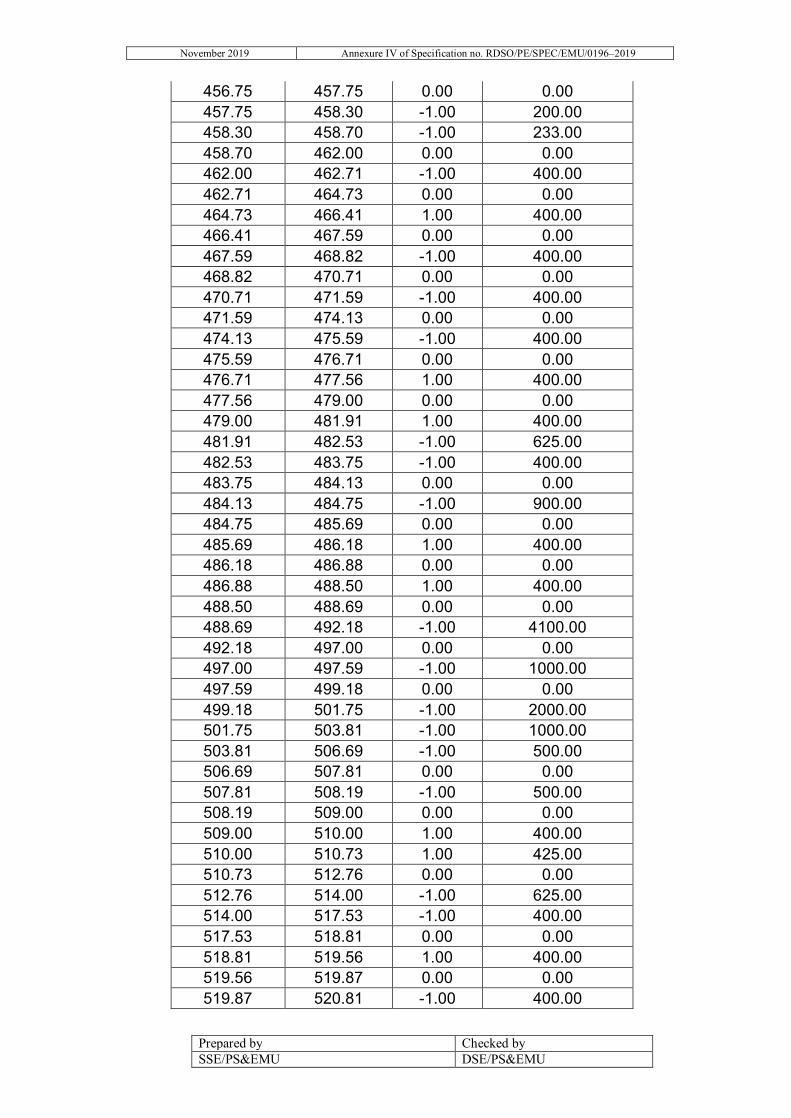
November 2019 Annexure IV of Specification no. RDSO/PE/SPEC/EMU/0196–2019
Prepared by Checked by SSE/PS&EMU DSE/PS&EMU
456.75 457.75 0.00 0.00 457.75 458.30 -1.00 200.00 458.30 458.70 -1.00 233.00 458.70 462.00 0.00 0.00 462.00 462.71 -1.00 400.00 462.71 464.73 0.00 0.00 464.73 466.41 1.00 400.00 466.41 467.59 0.00 0.00 467.59 468.82 -1.00 400.00 468.82 470.71 0.00 0.00 470.71 471.59 -1.00 400.00 471.59 474.13 0.00 0.00 474.13 475.59 -1.00 400.00 475.59 476.71 0.00 0.00 476.71 477.56 1.00 400.00 477.56 479.00 0.00 0.00 479.00 481.91 1.00 400.00 481.91 482.53 -1.00 625.00 482.53 483.75 -1.00 400.00 483.75 484.13 0.00 0.00 484.13 484.75 -1.00 900.00 484.75 485.69 0.00 0.00 485.69 486.18 1.00 400.00 486.18 486.88 0.00 0.00 486.88 488.50 1.00 400.00 488.50 488.69 0.00 0.00 488.69 492.18 -1.00 4100.00 492.18 497.00 0.00 0.00 497.00 497.59 -1.00 1000.00 497.59 499.18 0.00 0.00 499.18 501.75 -1.00 2000.00 501.75 503.81 -1.00 1000.00 503.81 506.69 -1.00 500.00 506.69 507.81 0.00 0.00 507.81 508.19 -1.00 500.00 508.19 509.00 0.00 0.00 509.00 510.00 1.00 400.00 510.00 510.73 1.00 425.00 510.73 512.76 0.00 0.00 512.76 514.00 -1.00 625.00 514.00 517.53 -1.00 400.00 517.53 518.81 0.00 0.00 518.81 519.56 1.00 400.00 519.56 519.87 0.00 0.00 519.87 520.81 -1.00 400.00

November 2019 Annexure IV of Specification no. RDSO/PE/SPEC/EMU/0196–2019
Prepared by Checked by SSE/PS&EMU DSE/PS&EMU
520.81 521.81 0.00 0.00 521.81 523.53 1.00 1000.00 523.53 524.63 1.00 500.00 524.63 525.00 0.00 0.00 525.00 528.76 1.00 500.00 528.76 531.86 0.00 0.00 531.86 532.81 -1.00 500.00 532.81 534.47 0.00 0.00 534.47 535.21 -1.00 500.00 535.21 536.41 0.00 0.00 536.41 536.82 1.00 500.00 536.82 539.41 0.00 0.00 539.41 539.94 1.00 500.00 539.94 542.06 0.00 0.00 542.06 542.82 1.00 333.00 542.82 543.82 0.00 0.00 543.82 545.07 1.00 400.00 545.07 546.76 1.00 500.00 546.76 546.88 0.00 0.00 546.88 547.50 -1.00 666.00 547.50 549.47 0.00 0.00 549.47 550.19 1.00 400.00 550.19 553.25 0.00 0.00 553.25 553.94 -1.00 500.00 553.94 555.06 0.00 0.00 555.06 555.69 1.00 500.00 555.69 555.94 0.00 0.00 555.94 556.94 -1.00 625.00 556.94 558.87 0.00 0.00 558.87 559.63 1.00 2000.00 559.63 561.25 0.00 0.00 561.25 561.94 1.00 1000.00 561.94 562.53 0.00 0.00 562.53 563.63 1.00 1000.00 563.63 569.29 0.00 0.00 569.29 570.50 -1.00 500.00 570.50 570.81 0.00 0.00 570.81 571.67 -1.00 666.00 571.67 574.19 0.00 0.00 574.19 576.38 -1.00 625.00 576.38 577.76 -1.00 500.00 577.76 578.63 -1.00 2000.00 578.63 579.69 -1.00 1000.00 579.69 581.88 -1.00 1754.00 581.88 582.81 0.00 0.00
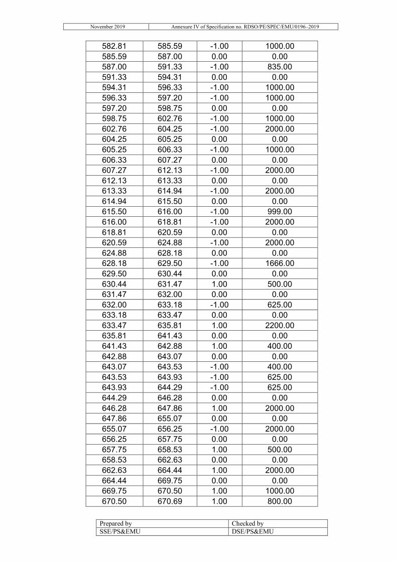
November 2019 Annexure IV of Specification no. RDSO/PE/SPEC/EMU/0196–2019
Prepared by Checked by SSE/PS&EMU DSE/PS&EMU
582.81 585.59 -1.00 1000.00 585.59 587.00 0.00 0.00 587.00 591.33 -1.00 835.00 591.33 594.31 0.00 0.00 594.31 596.33 -1.00 1000.00 596.33 597.20 -1.00 1000.00 597.20 598.75 0.00 0.00 598.75 602.76 -1.00 1000.00 602.76 604.25 -1.00 2000.00 604.25 605.25 0.00 0.00 605.25 606.33 -1.00 1000.00 606.33 607.27 0.00 0.00 607.27 612.13 -1.00 2000.00 612.13 613.33 0.00 0.00 613.33 614.94 -1.00 2000.00 614.94 615.50 0.00 0.00 615.50 616.00 -1.00 999.00 616.00 618.81 -1.00 2000.00 618.81 620.59 0.00 0.00 620.59 624.88 -1.00 2000.00 624.88 628.18 0.00 0.00 628.18 629.50 -1.00 1666.00 629.50 630.44 0.00 0.00 630.44 631.47 1.00 500.00 631.47 632.00 0.00 0.00 632.00 633.18 -1.00 625.00 633.18 633.47 0.00 0.00 633.47 635.81 1.00 2200.00 635.81 641.43 0.00 0.00 641.43 642.88 1.00 400.00 642.88 643.07 0.00 0.00 643.07 643.53 -1.00 400.00 643.53 643.93 -1.00 625.00 643.93 644.29 -1.00 625.00 644.29 646.28 0.00 0.00 646.28 647.86 1.00 2000.00 647.86 655.07 0.00 0.00 655.07 656.25 -1.00 2000.00 656.25 657.75 0.00 0.00 657.75 658.53 1.00 500.00 658.53 662.63 0.00 0.00 662.63 664.44 1.00 2000.00 664.44 669.75 0.00 0.00 669.75 670.50 1.00 1000.00 670.50 670.69 1.00 800.00

November 2019 Annexure IV of Specification no. RDSO/PE/SPEC/EMU/0196–2019
Prepared by Checked by SSE/PS&EMU DSE/PS&EMU
670.69 671.94 1.00 625.00 671.94 684.91 0.00 0.00 684.91 686.88 1.00 1200.00 686.88 687.38 0.00 0.00 687.38 688.88 -1.00 1000.00 688.88 691.13 1.00 1250.00 691.13 693.13 0.00 0.00 693.13 695.16 -1.00 1000.00 695.16 695.95 -1.00 500.00 695.95 696.84 0.00 0.00 696.84 698.28 1.00 500.00 698.28 703.28 0.00 0.00 703.28 704.63 1.00 500.00 704.63 705.25 0.00 0.00 705.25 706.00 -1.00 500.00 706.00 709.50 0.00 0.00 709.50 711.00 1.00 500.00 711.00 714.28 0.00 0.00 714.28 715.41 -1.00 500.00 715.41 717.69 1.00 1000.00 717.69 718.82 0.00 0.00 718.82 719.88 1.00 500.00 719.88 722.00 0.00 0.00 722.00 723.75 -1.00 666.67 723.75 725.44 0.00 0.00 725.44 730.88 1.00 8333.33 730.88 731.38 0.00 0.00 731.38 731.88 -1.00 500.00 731.88 734.63 -1.00 1000.00 734.63 740.88 0.00 0.00 740.88 742.00 -1.00 500.00 742.00 743.00 1.00 500.00 743.00 744.69 0.00 0.00 744.69 745.69 -1.00 500.00 745.69 748.69 0.00 0.00 748.69 749.32 -1.00 500.00 749.32 754.94 0.00 0.00 754.94 759.94 1.00 666.67 759.94 774.88 0.00 0.00 774.88 776.32 -1.00 1000.00 776.32 790.95 0.00 0.00 790.95 792.22 1.00 600.00 792.22 792.66 0.00 0.00 792.66 793.81 -1.00 600.00 793.81 798.13 0.00 0.00

November 2019 Annexure IV of Specification no. RDSO/PE/SPEC/EMU/0196–2019
Prepared by Checked by SSE/PS&EMU DSE/PS&EMU
798.13 800.25 1.00 1000.00 800.25 810.00 0.00 0.00 810.00 811.88 1.00 1000.00 811.88 818.06 0.00 0.00 818.06 820.88 1.00 1000.00 820.88 824.19 0.00 0.00 824.19 824.76 -1.00 500.00 824.76 831.70 0.00 0.00 831.70 837.04 1.00 2500.00 837.04 842.32 1.00 3333.33 842.32 853.38 0.00 0.00 853.38 856.38 1.00 2000.00 856.38 860.88 1.00 10000.00 860.88 865.76 0.00 0.00 865.76 870.63 1.00 4000.00 870.63 875.81 0.00 0.00 875.81 882.50 1.00 3333.33 882.50 889.63 0.00 0.00 889.63 896.57 1.00 6666.67 896.57 901.44 0.00 0.00 901.44 907.57 1.00 2500.00 907.57 913.80 0.00 0.00 913.80 917.57 1.00 2000.00 917.57 923.07 0.00 0.00 923.07 928.22 1.00 2000.00 928.22 939.13 0.00 0.00 939.13 941.63 1.00 2000.00 941.63 944.13 0.00 0.00 944.13 966.75 1.00 3333.33 966.75 979.75 0.00 0.00 979.75 983.44 -1.00 1000.00 983.44 983.81 0.00 0.00 983.81 987.39 1.00 1000.00 987.39 991.63 1.00 2500.00 991.63 997.84 0.00 0.00 997.84 1002.19 1.00 2500.00
1002.19 1003.79 0.00 0.00 1003.79 1012.79 1.00 4000.00 1012.79 1018.44 0.00 0.00 1018.44 1020.16 1.00 1000.00 1020.16 1021.83 -1.00 2000.00 1021.83 1023.69 0.00 0.00 1023.69 1024.00 1.00 1000.00 1024.00 1025.57 1.00 602.41 1025.57 1025.69 0.00 0.00

November 2019 Annexure IV of Specification no. RDSO/PE/SPEC/EMU/0196–2019
Prepared by Checked by SSE/PS&EMU DSE/PS&EMU
1025.69 1027.22 -1.00 602.41 1027.22 1034.64 0.00 0.00 1034.64 1035.63 1.00 1000.00 1035.63 1039.00 1.00 2800.00 1039.00 1041.88 -1.00 2000.00 1041.88 1045.00 1.00 2000.00 1045.00 1049.50 1.00 10000.00 1049.50 1051.75 1.00 1000.00 1051.75 1058.13 0.00 0.00 1058.13 1061.16 1.00 1000.00 1061.16 1066.69 -1.00 5000.00 1066.69 1070.07 1.00 2500.00 1070.07 1080.00 1.00 6000.00 1080.00 1083.44 0.00 0.00 1083.44 1085.00 1.00 2000.00 1085.00 1091.88 1.00 6000.00 1091.88 1099.50 1.00 4000.00 1099.50 1114.50 1.00 6000.00 1114.50 1125.00 1.00 4500.00 1125.00 1134.44 0.00 0.00 1134.44 1137.50 1.00 2500.00 1137.50 1140.50 -1.00 2500.00 1140.50 1142.69 0.00 0.00 1142.69 1151.32 1.00 2000.00 1151.32 1151.44 0.00 0.00 1151.44 1151.88 1.00 428.00 1151.88 1152.19 -1.00 1500.00 1152.19 1152.66 1.00 6400.00 1152.66 1153.63 1.00 2000.00 1153.63 1160.94 -1.00 6000.00 1160.94 1165.38 1.00 3000.00 1165.38 1165.50 1.00 1500.00 1165.50 1166.16 1.00 600.00 1166.16 1166.44 1.00 366.00 1166.44 1166.82 -1.00 400.00 1166.82 1167.13 -1.00 1000.00 1167.13 1167.38 -1.00 2500.00 1167.38 1170.95 0.00 0.00 1170.95 1175.50 1.00 2500.00 1175.50 1177.94 -1.00 6000.00 1177.94 1181.25 1.00 3000.00 1181.25 1181.88 1.00 160.00 1181.88 1182.00 -1.00 2000.00 1182.00 1182.25 -1.00 1000.00 1182.25 1186.63 1.00 3000.00
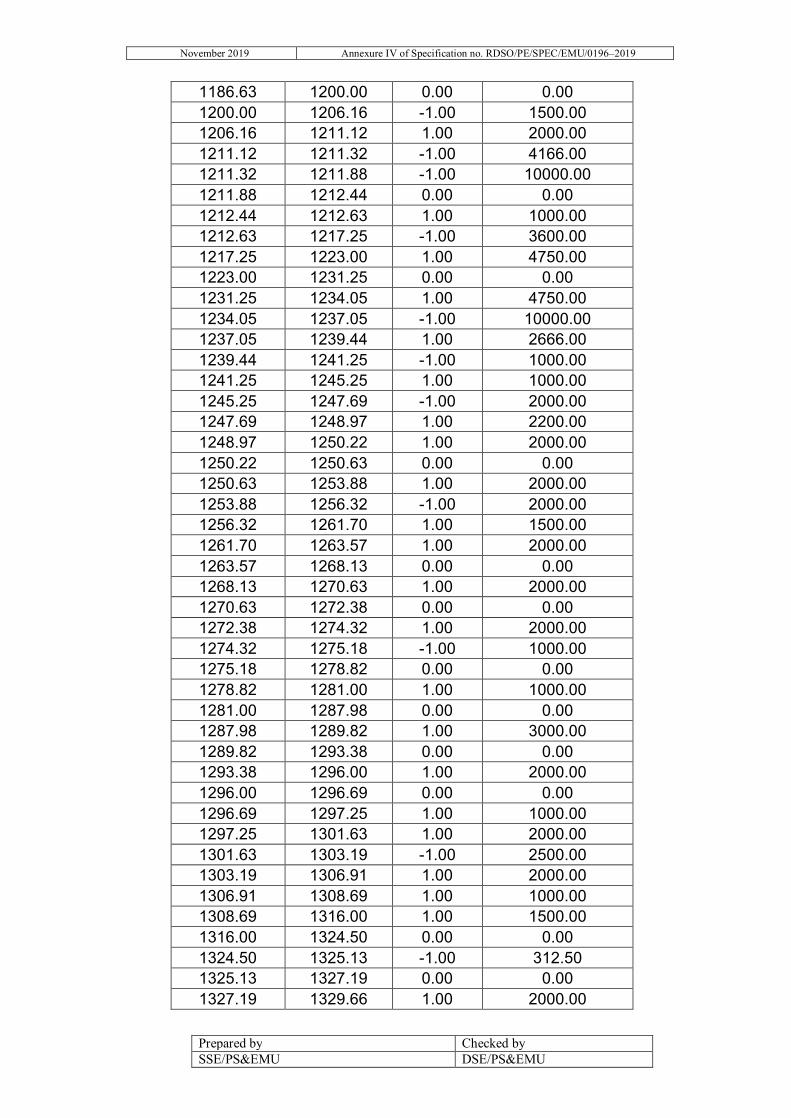
November 2019 Annexure IV of Specification no. RDSO/PE/SPEC/EMU/0196–2019
Prepared by Checked by SSE/PS&EMU DSE/PS&EMU
1186.63 1200.00 0.00 0.00 1200.00 1206.16 -1.00 1500.00 1206.16 1211.12 1.00 2000.00 1211.12 1211.32 -1.00 4166.00 1211.32 1211.88 -1.00 10000.00 1211.88 1212.44 0.00 0.00 1212.44 1212.63 1.00 1000.00 1212.63 1217.25 -1.00 3600.00 1217.25 1223.00 1.00 4750.00 1223.00 1231.25 0.00 0.00 1231.25 1234.05 1.00 4750.00 1234.05 1237.05 -1.00 10000.00 1237.05 1239.44 1.00 2666.00 1239.44 1241.25 -1.00 1000.00 1241.25 1245.25 1.00 1000.00 1245.25 1247.69 -1.00 2000.00 1247.69 1248.97 1.00 2200.00 1248.97 1250.22 1.00 2000.00 1250.22 1250.63 0.00 0.00 1250.63 1253.88 1.00 2000.00 1253.88 1256.32 -1.00 2000.00 1256.32 1261.70 1.00 1500.00 1261.70 1263.57 1.00 2000.00 1263.57 1268.13 0.00 0.00 1268.13 1270.63 1.00 2000.00 1270.63 1272.38 0.00 0.00 1272.38 1274.32 1.00 2000.00 1274.32 1275.18 -1.00 1000.00 1275.18 1278.82 0.00 0.00 1278.82 1281.00 1.00 1000.00 1281.00 1287.98 0.00 0.00 1287.98 1289.82 1.00 3000.00 1289.82 1293.38 0.00 0.00 1293.38 1296.00 1.00 2000.00 1296.00 1296.69 0.00 0.00 1296.69 1297.25 1.00 1000.00 1297.25 1301.63 1.00 2000.00 1301.63 1303.19 -1.00 2500.00 1303.19 1306.91 1.00 2000.00 1306.91 1308.69 1.00 1000.00 1308.69 1316.00 1.00 1500.00 1316.00 1324.50 0.00 0.00 1324.50 1325.13 -1.00 312.50 1325.13 1327.19 0.00 0.00 1327.19 1329.66 1.00 2000.00

November 2019 Annexure IV of Specification no. RDSO/PE/SPEC/EMU/0196–2019
Prepared by Checked by SSE/PS&EMU DSE/PS&EMU
1329.66 1332.05 0.00 0.00 1332.05 1333.32 1.00 2000.00 1333.32 1334.44 0.00 0.00 1334.44 1336.32 1.00 1000.00 1336.32 1341.82 0.00 0.00 1341.82 1343.00 1.00 1000.00 1343.00 1345.13 0.00 0.00 1345.13 1347.00 1.00 2000.00 1347.00 1347.63 1.00 1000.00 1347.63 1350.34 0.00 0.00 1350.34 1351.44 1.00 1000.00 1351.44 1357.63 1.00 2000.00 1357.63 1359.19 0.00 0.00 1359.19 1360.32 -1.00 1000.00 1360.32 1366.44 0.00 0.00 1366.44 1368.82 1.00 2000.00 1368.82 1370.07 0.00 0.00 1370.07 1372.25 1.00 1000.00 1372.25 1372.69 1.00 1500.00 1372.69 1373.44 0.00 0.00 1373.44 1384.69 1.00 2000.00 1384.69 1387.38 0.00 0.00 1387.38 1392.00 1.00 1500.00 1392.00 1396.25 0.00 0.00 1396.25 1396.73 1.00 1500.00 1396.73 1398.35 0.00 0.00 1398.35 1399.44 1.00 10000.00 1399.44 1400.13 -1.00 800.00 1400.13 1400.25 0.00 0.00 1400.25 1401.00 -1.00 785.00 1401.00 1402.00 -1.00 625.00 1402.00 1406.13 0.00 0.00 1406.13 1409.76 1.00 2000.00 1409.76 1415.88 0.00 0.00 1415.88 1416.25 1.00 1818.00 1416.25 1416.65 1.00 1160.00 1416.65 1418.63 -1.00 2000.00 1418.63 1421.35 0.00 0.00 1421.35 1422.57 1.00 1000.00 1422.57 1433.00 0.00 0.00 1433.00 1439.00 0.00 0.00 1439.00 1440.00 -1.00 500.00 1440.00 1441.00 -1.00 1000.00 1441.00 1442.00 0.00 0.00 1442.00 1444.00 -1.00 557.00
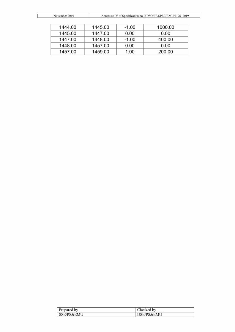
November 2019 Annexure IV of Specification no. RDSO/PE/SPEC/EMU/0196–2019
Prepared by Checked by SSE/PS&EMU DSE/PS&EMU
1444.00 1445.00 -1.00 1000.00 1445.00 1447.00 0.00 0.00 1447.00 1448.00 -1.00 400.00 1448.00 1457.00 0.00 0.00 1457.00 1459.00 1.00 200.00

November 2019 Annexure V of Specification no. RDSO/PE/SPEC/EMU/0196–2019
Prepared by Checked by SSE/PS&EMU DSE/PS&EMU
ANNEXURE V LIMITS OF INTERFERENCE CURRENTS
S. No. Interference Current Over all limit
1. Psophometric current AC traction 10.0 A 2. DC components in AC mode 4.7 A 3. Second Harmonic Component (100Hz) in AC
traction per basic unit 0.5 A
4. 1400 Hz to 5000 Hz 400 mA 5. More than 5000 Hz up to 50000 Hz 270 mA 6. 50 Hz components in DC mode 2.4 A
Interference limit for Signal Equipment: 1. Limit of AFTC compatibility shall be demonstrated as per IEC 62427/EN-50238 for used on
Indian Railways. i) M/s Siemens make AFTC (FTGS46/FTGS917/TCM100): Limits as defined TableA.3 of EN-
50238-2:2015 as below.
Type F0[Hz] I0RMS[A] ∆ F3dB ∆F20dB[Hz] T[S] Tp[s]
FTGS 46 4750 1 200 560 0.04 0.12
FTGS 46 5250 1 206 570 0.04 0.12
FTGS 46 5750 1 214 580 0.04 0.12
FTGS 46 6250 1 220 590 0.04 0.12
FTGS 917 9500 0.33 360 900 0.04 0.12
FTGS 917 10500 0.33 380 920 0.04 0.12
FTGS 917 11500 0.33 400 950 0.04 0.12
FTGS 917 12500 0.33 425 1015 0.04 0.12
FTGS 917 13500 0.33 445 1100 0.04 0.12
FTGS 917 14500 0.33 470 1160 0.04 0.12
FTGS 917 15500 0.33 490 1195 0.04 0.12
FTGS 917 16500 0.33 510 1230 0.04 0.12
ii) M/s Alstom make AFTC (DTC 24): Limits as defined in Table A.9 (Digicode) of EN-50238-
2:2015 as below.
Type F0[Hz] I0 RMS[A] ∆F3dB ∆F20db[Hz] 2*N[-] T[S]
DTC24-2 2100 2.2 400 440 10 1

November 2019 Annexure V of Specification no. RDSO/PE/SPEC/EMU/0196–2019
Prepared by Checked by SSE/PS&EMU DSE/PS&EMU
DTC24-2 2500 2.2 400 440 10 1
DTC24-2 2900 1.5 400 440 10 1
DTC24-2 3300 1.5 400 440 10 1
DTC24-2 3700 1.5 400 440 10 1
DTC24-2 4100 1.5 400 440 10 1
DTC24-2 4500 1.5 400 440 10 1
DTC24-2 4900 1.5 400 440 10 1
iii) M/s Ansaldo make AFTC (UM-71): Limits as defined in Table A.13 of EN-50238-2:2015 as below.
Type F0[Hz] ∆F[Hz] I0 RMS[A] T[S]
All kind of UM71 equipped with RENUM receptor 1700 90 0.3 0.3
All kind of UM71 equipped with RENUM receptor 2000 90 0.3 0.3
All kind of UM71 equipped with RENUM receptor 2300 90 0.3 0.3
All kind of UM71 equipped with RENUM receptor 2600 90 0.3 0.3
UC9500 9500 100 0.3 0.3
iv) M/s Bombardier make AFTC (TI 21): Limits as per Table A.16 of EN-50238-2:2015 as below.
Type F0[Hz] ∆F[Hz] I0RMS[A] ∆F3dB ∆F20dB[Hz] Ti[S] Remark
E 1549 ±17 0.134 12 60 0.04 Analysis technique
digital filter
A 1699 ±17 0.101 12 60 0.04
G 1848 ±17 0.142 12 60 0.04
C 1996 ±17 0.091 12 60 0.04
F 2146 ±17 0.148 12 60 0.04
B 2296 ±17 0.132 12 60 0.04
H 2445 ±17 0.143 12 60 0.04
D 2593 ±17 0.167 12 60 0.04
The compatibility plan to be made as per EN-50238 where limits of current generated by all Rolling stock should not be more than the above limit the current returning from each rolling stock towards TSS will go through the AFTC present

November 2019 Annexure V of Specification no. RDSO/PE/SPEC/EMU/0196–2019
Prepared by Checked by SSE/PS&EMU DSE/PS&EMU
between all rolling stock and TSS and will add up in worst case. The summation rule as per clause B.8.2 of EN-50238-2:2015 shall be used to work out the Max. Permissible current limit generated by one Rolling Stock. This shall be clearly defined in the Test Plan to be submitted to RDSO. 2. Axle Counter Compatibility as per EN 50238:-
i) The measurement shall be done as per EN: 50238-3:2013 and EN-50592:2016. The following are the limits for different type of Axle counter used on Indian Railways as on date.
Axle counter make & model
Centre frequency tolerance range KHz
Filter curve 3 dB/20dB bandwidth KHz
Filter order using for evaluation
Magnetic field in X direction rms dBµA/m
Magnetic field in Y direction rms dBµA/m
Magnetic field in Z direction rms dBµA/m
Rail current UIC 60rms mA
Integration time Tint ms
M/s Siemens make (ZP D 43, ZP D 43 I)
43.0±1.7 ±0.02/±0.3
2 100 85 98 68 2
M/s Siemens make (ZP 43 E)
43.0±1.0 ±0.16/±1.2
4 100 83 to 90d
98 68 1
M/s Frauscher make(RSR180)
250±1.0 ±5.0/±15 4 121 113.8 101.0 277.6 1.5
M/s Eldyne/Thales make(ZP30H, Zp30 C-NT, Zp30, Zp 30K)
27.0-32.0 ±0.12/±0.45
4 114 94 101 220 4
M/s G. G. Tronics India Pvt. Ltd.
Limit shall be informed later. M/s Nippon Signal India Private Limited
M/s Medha Servo Drives Pvt. Ltd.
M/s Central Electronics Ltd
M/s Signal & Telecom Workshop
3. As per EN-50238, the agency conducting the test shall preferably be certified to EN
ISO/IEC 17025. The rake shall be certified for EN-50121 for radiated EMI. 4. The compatibility with TPWS/TCAS equipment shall be covered. The rake shall be
complied to EN-50121 for Radiated EMI. The compatibility from the requirement of space to accommodate the existing TPWS/TCAS equipment in Trainset etc. shall also be covered.

November 2019 Annexure VI of Specification no. RDSO/PE/SPEC/EMU/0196–2019
Prepared by Checked by SSE/PS&EMU DSE/PS&EMU
ANNEXURE – VI
A. TELECOMMUNICATION CABLING INSTALLATIONS (1) Telecom copper cable to the specification IRS: TC 14/75. TO 27/77, TC 41/97,
RDSO/SPN/TC/72/2007 and IRS: TC 30/05 laid along the track. These may carry typically following types of circuits:-
(i) Control Circuit (a) Speech VF-band
(c) Signaling 50 Hz interrupted at 3-1/2 cycles per sec.
(ii) VF Telegraphy 150 Hz 1620 Hz (iii) Tele printer 150 Hz 1620 Hz (iv) Truck circuit speech VF Band and signalling-17 Hz,50 Hz,150 Hz (v) Gate control Speech VF Band and signalling-17 Hz
(vi) Block Bell and Train Wire 150 Hz.
(vii) Carrier circuits 1+3stackable carrier Speech communication
eqpt. 3.9Hz to 11kHz plus data transmission
(viii) FAX circuit (ix) PRS circuit
(2) Armoured optic fibre cable as per IRS TC 55-98 laid along with the track to carry the
above telecom circuits 1 (i) to 1 (ix) by converting analogue information into digital and transmitting the information on optical medium at 2 Mbps. 8 Mbps. 34 Mbps. PDH heirchy and at 155 Mbps STM1=SDH heirchy. Associated optical line equipments and multiplexing equipments shall also be installed at every station.
B. RADIO COMMUNICATION i) HF communication 2-16 MHz For speech communication (SSB and DSB working) And data transmission ii) VHF Links 68-87 MHz 146-163 MHz iii) UHF 437-445 MHz 462-470 MHz 314-322 MHz iv) Microwave 7124-7245 MHz 1.8-2.4 GHz

November 2019 Annexure VI of Specification no. RDSO/PE/SPEC/EMU/0196–2019
Prepared by Checked by SSE/PS&EMU DSE/PS&EMU
17.7-19.7 GHz
MISCELLANEOUS i) Clock network Square wave pulse 1 in 5 sec. ii) PA equipment, VF Band IVRS, PC Based. Display & Announcement iii) CCTV 3 MHz C. AUXILIARY WARNING SYSTEM
There should be no adverse effect on the working AWS in Mumbai area - Carrier frequencies are 50 kHz and 100 kHz. - Equipment control frequencies for various - Functions are 2800 c/s - 3600 c/s - 4400 c/s - 5200 c/s - 6000 c/s - 6800 c/s - 7600 c/s

November 2019 Annexure VII of Specification no. RDSO/PE/SPEC/EMU/0196–2019
Prepared by Checked by SSE/PS&EMU DSE/PS&EMU
Annexure-VII TIME TABLE OF RAJDHANI TRAIN:

November 2019 Annexure VIII of Specification no. RDSO/PE/SPEC/EMU/0196–2019
Prepared by Checked by SSE/PS&EMU DSE/PS&EMU
Annexure VIII

November 2019 Annexure IX of Specification no. RDSO/PE/SPEC/EMU/0196–2019
Prepared by Checked by SSE/PS&EMU DSE/PS&EMU
Annexure-IX
INDICATIVE LIST OF EQUIPMENTS FOR WHICH MTBF/MDBF TO BE SUBMITTED
S.
No. Equipment MTBF/MDBF
1. Traction Transformer 2. Traction Motor 3. Traction Converter 4. IGBT modules 5. Pantograph 6. Compressor, Air Dryer & Filters 7. Vacuum Circuit Breaker 8. Lightning Arrestors 9. Auxiliary Converter
10. Master cum Brake Controller 11. Train Control & Management System 12. Passenger Information & Communication
system
13. Cables 14. Inter Vehicular couplers 15. Brake Electronic Control Unit 16. RMPU 17. CCTV 18. Car light 19. Sensors 20. Drive Control Unit 21. Gate Drive Unit 22. HMI 23. Display Panel 24. Head Light