Embed Size (px)
Citation preview
Oshkosh Corporation Classification - Restricted
Manual Part # 99901222
2020 Parts & Specifications
Revised: July 17, 2019
IOWA MOLD TOOLING CO., INC.
PO Box 189 Garner, IA 50438
Tel: 641-923-3711 FAX: 641-923-2424 Website: http://www.imt.com
Copyright © 2019 Iowa Mold Tooling Co., Inc. All rights reserved
No part of this publication may be reproduced, stored in a retrieval system, or transmitted in any form or by any means, electronic, mechanical, photocopying, recording or otherwise without the prior written permission of Iowa Mold Tooling Co., Inc.
Iowa Mold Tooling Co., Inc. is an Oshkosh Corporation Company.

i
Oshkosh Corporation Classification - Restricted
ii Contents
Oshkosh Corporation Classification - Restricted
Contents
Revisions ...................................................................................................................................................... v
Introduction 7
Specifications 9
General Specifications .................................................................................................................................. 9 Performance Characteristics ....................................................................................................................... 10 2020 Geometric Configuration ................................................................................................................... 12 2020 Capacity Chart ................................................................................................................................... 13
Crane Reference 15
Crane Assemblies & Grease Zerks ............................................................................................................. 15 2020 Recommended Spare Parts List ......................................................................................................... 16 Crane Installation ........................................................................................................................................ 18 Telescopic Crane Orientation ..................................................................................................................... 20 Electric Remote Handle Operating Instructions ......................................................................................... 21 Remote Engine Speed Control (From Crane) ............................................................................................. 22
Parts 23
Parts Information ........................................................................................................................................ 24 Base & Mast Assemblies ............................................................................................................................ 26
Base Assembly (41704555) ............................................................................................................. 26 Mast Assembly (41714277) ............................................................................................................. 28 Cord Reel Assembly (51713168) .................................................................................................... 29
Boom Assemblies & Cylinders ................................................................................................................... 30 Lower Boom Assembly (41715074) ............................................................................................... 30 Lower Boom Cylinder (3B200010) (Thru 9-05, Eff. 4-07) ............................................................. 32 Lower Boom Cylinder (71411800) (Eff. 10-05 through 3-07) ........................................................ 34 Counterbalance Valve Assembly (73540057) ................................................................................. 35 Extension Boom Assembly, 15-foot (41714487) ............................................................................ 36 Extension Boom Assembly, 20-foot (41714486) ............................................................................ 38 Installation - Manual Extension Boom Stop (99905213) ................................................................ 40 Extension Cylinder (3B185010) (Thru. 9-05, Eff. 5-07) ................................................................. 41 Extension Cylinder (71411799) (Eff. 10-05 through 4-07) ............................................................. 43
Boom Light Kit (99906232) ....................................................................................................................... 44 Boom Light Kit (99906232) ....................................................................................................................... 49
99906232-1 ...................................................................................................................................... 51 99906232-2 ...................................................................................................................................... 52 99906232-3 ...................................................................................................................................... 53
Harness, LED Boom Tip Jumper (77441689) ............................................................................................ 54 Winch/Cable/Hook Kit (41714444) Effective: 2-9-2017............................................................................ 56 Winch/Cable/Hook Kit (41714444) (Effective thru: 2-8-17) ..................................................................... 58
Cable & Hook Kit (51725231) Effective: 10-5-2015 ...................................................................... 60
Contents iii
Oshkosh Corporation Classification - Restricted
Cable & Hook Kit (51725231) (Effective From 05/30/13) ......................................................................... 61 Cable & Hook Kit (31704560) (Effective Through 05/30/13) ........................................................ 62 Winch (71057987) ........................................................................................................................... 63
Controls & Hydraulics, Power Unit ............................................................................................................ 65 Hydraulic Power Unit - DC (73051957) .......................................................................................... 65 Control Kit, Power Unit (91714441) ............................................................................................... 67 Schematic, Power Unit (99901153) ................................................................................................. 68 Hydraulic Kit, Power Unit (91715660) ........................................................................................... 69 Valvebank, Power Unit (70733398) ................................................................................................ 71 Handle Assembly, Remote, Power Unit (51716404) ....................................................................... 73
Controls & Hydraulics, PTO....................................................................................................................... 76 Control Kit - Tethered Remote (91714443) .................................................................................... 76 Schematic, Proportional Remote Control (99900990) ..................................................................... 77 Hydraulic Kit, Prop'l PTO (91715659) ............................................................................................ 78
Valve Bank, 4 Sec 4R PROPN 2000 DRVR (73735157) Effective 07/2019, this replaces 70733399 ....... 80 Valve Bank, Tethered Remote (73735157) EFFECTIVE: 2-15-2019 ....................................................... 82
Valve Bank, Tethered Remote (70733399) EFFECTIVE THROUGH: 2-15-2019 ........................ 83 Control Kit, Non-Proportional PTO (91714439) ............................................................................. 85 Schematic, Non-Prop Remote Control (99901049) ......................................................................... 86 Hydraulic Kit, Non-Proportional PTO (91715662) ......................................................................... 87 Valvebank, Non-Prop Remote Control (70733400) ........................................................................ 89 Handle Assembly, Remote, PTO On/Off (51713384) ..................................................................... 91 Handle Assembly, PTO Prop (51713182) ....................................................................................... 93 Cable Assembly, Tethered Remote (70733394) .............................................................................. 96
Controls & Hydraulics, Radio Remote ..................................................................................................... 101 Control Kit, Radio Remote (90718830) (REF 99903629) ............................................................. 101 Hydraulic Kit, Radio Remote (91715631) ..................................................................................... 102 Valvebank, Radio Remote (73733931) ......................................................................................... 104 Cable Assembly, Radio Remote (77441101) ................................................................................ 105 Electrical Schematic, Radio Remote (77441101) .......................................................................... 106
Stabilizers (Reference 99905457 Auxiliary Stabilizer Manual) ............................................................... 108 Miscellaneous ........................................................................................................................................... 109
Reservoir Assembly (51706910) ................................................................................................... 109 Reservoir (51707798) .................................................................................................................... 110 Decal Placement, 2020 PTO (99903725) Effective 10-6-14 ......................................................... 111 Decal Placement, 2020 PTO (99903725) ...................................................................................... 112 Decal Placement, 2020 Pump (99903726) .................................................................................... 114 Decal Placement, 2020 Pump (99903726) .................................................................................... 115 Installation Kit, 2020 Power Unit (93714598) .............................................................................. 117
PTO Mounting Kit (93715347) ................................................................................................................ 119 Installation Kit, 2020 PTO (93715347) .................................................................................................... 120
Chassis Wiring Harness (99903340) ............................................................................................. 121
iv Contents
Oshkosh Corporation Classification - Restricted
General Reference 123
Inspection Checklist .................................................................................................................................. 123 Deficiency / Recommendation / Corrective Action Report ...................................................................... 128 Wire Rope Inspection & Replacement...................................................................................................... 130 Hook Inspection ........................................................................................................................................ 131 Holding Valve Inspection ......................................................................................................................... 132 Anti-Two-Block Device Inspection .......................................................................................................... 132 Thread Torque Chart (English) ................................................................................................................. 133 Thread Torque Chart (Metric) .................................................................................................................. 134 Turntable Bearing Thread Tightening Sequence ...................................................................................... 135 Turntable Bearing Inspection .................................................................................................................... 136 Turntable Bearing Tilt Test ....................................................................................................................... 136
Contents v
Oshkosh Corporation Classification - Restricted
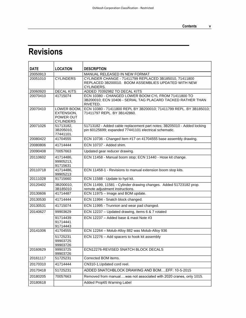
Revisions
DATE LOCATION DESCRIPTION
20050913 MANUAL RELEASED IN NEW FORMAT
20051010 CYLINDERS CYLINDER CHANGE - 71411799 REPLACED 3B185010, 71411800 REPLACED 3B200010. BOOM ASSEMBLIES UPDATED WITH NEW CYLINDERS.
20060920 DECAL KITS ADDED 70392982 TO DECAL KITS
20070410 41715074 ECN 10380 - CHANGED LOWER BOOM CYL FROM 71411800 TO 3B200010; ECN 10406 - SERIAL TAG PLACARD TACKED RATHER THAN RIVETED.
20070410 LOWER BOOM, EXTENSION, POWER OUT CYLINDERS
ECN 10380 - 71411800 REPL BY 3B200010; 71411799 REPL. BY 3B185010; 71411797 REPL. BY 3B142860.
20071026 51713182, 3B205010, 77441101.
51713182 - Added cable replacement part notes; 3B205010 - Added locking pin 60125699; expanded 77441101 electrical schematic.
20080422 41704555 ECN 10736 - Changed item #17 on 41704555 base assembly drawing.
20080806 41714444 ECN 10737 - Added shim.
20090408 70057663 Updated gear reducer drawing.
20110602 41714486, 99905213, 91715631
ECN 11458 - Manual boom stop; ECN 11440 - Hose kit change.
20110718 41714486, 99905213
ECN 11458-1 - Revisions to manual extension boom stop kits.
20111028 91715660 ECN 11588 - Update to hyd kit.
20120402 3B200010, 3B185010
ECN 11499, 11581 - Cylinder drawing changes. Added 51723182 prop. remote adjustment instructions.
20130606 41714487 ECN 11975 – Image and BOM update.
20130530 41714444 ECN 11994 - Snatch block changed.
20130531 41715074 ECN 11995 - Trunnion and wear pad changed.
20140627 99903629 ECN 12237 – Updated drawing, items 6 & 7 rotated
91714439 91714441 91714443
ECN 12237 – Added base & mast Note #3
20141006 41704555 ECN 12264 – Molub-Alloy 882 was Molub-Alloy 936
51725231 99903725 99903726
ECN 12276 – Add spacers to hook kit assembly
20160629 99903725 99903726
ECN12276-REVISED SNATCH BLOCK DECALS
20161117 51725231 Corrected BOM items.
20170310 41714444 CN310-1,Updated cord reel.
20170418 51725231 ADDED SNATCHBLOCK DRAWING AND BOM….EFF: 10-5-2015
20180205 70057663 Removed from manual….was not associated with 2020 cranes, only 1015.
20180618 Added Prop65 Warning Label

vi Contents
Oshkosh Corporation Classification - Restricted
20180618 Added GVWR 15,000 lb and removed front and rear axle weights.
20180814 93715347 CN751
20180827 77441689 CN844
20181129 99906232 CN632-2
20190717 73735157 CN933-1
7
Oshkosh Corporation Classification - Restricted
This volume includes specifications, installation information, and spare parts drawings applicable to your particular crane. For operating, maintenance and repair instructions, see Telescopic Crane Volume 1: OPERATION, MAINTENANCE AND REPAIR. (IMT part number 99903514.)
It is your responsibility to operate and maintain this unit in a manner that will result in the safest working conditions possible. You must be aware of existing Federal, State and Local codes and regulations governing the safe use and maintenance of this IMT crane. The crane was designed and built to meet the standards of ANSI/ASME B30.5, Mobile & Locomotive Cranes. Contact the American Society of Mechanical Engineers (www.asme.org) for more information on ANSI/ASME B30.5.
Misuse of the crane through overloading, abuse, lack of maintenance and unauthorized modifications will void the warranty on any part of the unit subjected to this misuse. No warranty - verbal, written or implied - other than the official, published IMT new machinery and equipment warranty will be valid with this unit.
Throughout the manual, NOTEs, CAUTIONs and WARNINGs are used to draw the attention of personnel. They are defined as follows:
For a safe work environment, treat this equipment with respect and service it regularly.
C H A P T E R 1
Introduction
CAUTIONA CAUTION is used when there is the
very strong possibility of damage to the
equipment or premature equipment
failure.
WARNING
A WARNING is used when there is the
potential for personal injury or death.
NOTE
A NOTE is used to either convey
additional information or to provide
further emphasis for a previous point.

9
Oshkosh Corporation Classification - Restricted
In This Chapter
General Specifications.............................................................. 9 Performance Characteristics .................................................... 10 2020 Geometric Configuration .................................................. 12 2020 Capacity Chart ................................................................. 13
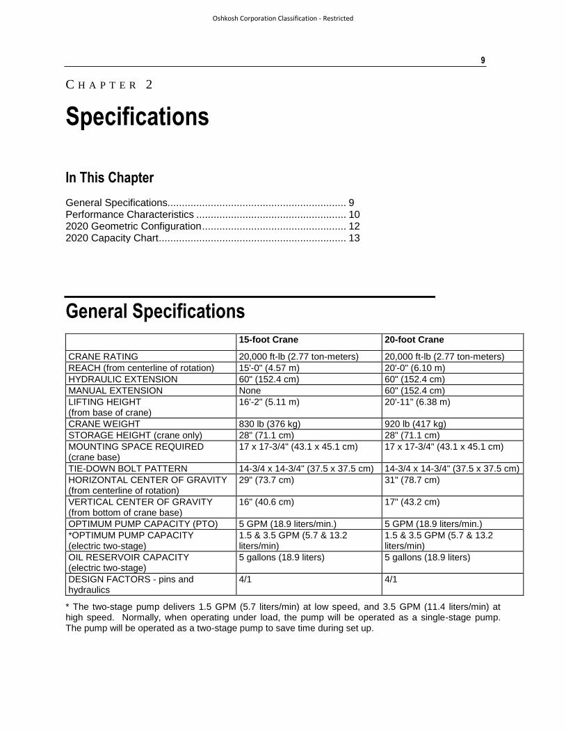
General Specifications
15-foot Crane 20-foot Crane
CRANE RATING 20,000 ft-lb (2.77 ton-meters) 20,000 ft-lb (2.77 ton-meters)
REACH (from centerline of rotation) 15'-0" (4.57 m) 20'-0" (6.10 m)
HYDRAULIC EXTENSION 60" (152.4 cm) 60" (152.4 cm)
MANUAL EXTENSION None 60" (152.4 cm)
LIFTING HEIGHT (from base of crane)
16'-2" (5.11 m) 20'-11" (6.38 m)
CRANE WEIGHT 830 lb (376 kg) 920 lb (417 kg)
STORAGE HEIGHT (crane only) 28" (71.1 cm) 28" (71.1 cm)
MOUNTING SPACE REQUIRED (crane base)
17 x 17-3/4" (43.1 x 45.1 cm) 17 x 17-3/4" (43.1 x 45.1 cm)
TIE-DOWN BOLT PATTERN 14-3/4 x 14-3/4" (37.5 x 37.5 cm) 14-3/4 x 14-3/4" (37.5 x 37.5 cm)
HORIZONTAL CENTER OF GRAVITY (from centerline of rotation)
29" (73.7 cm) 31" (78.7 cm)
VERTICAL CENTER OF GRAVITY (from bottom of crane base)
16" (40.6 cm) 17" (43.2 cm)
OPTIMUM PUMP CAPACITY (PTO) 5 GPM (18.9 liters/min.) 5 GPM (18.9 liters/min.)
*OPTIMUM PUMP CAPACITY (electric two-stage)
1.5 & 3.5 GPM (5.7 & 13.2 liters/min)
1.5 & 3.5 GPM (5.7 & 13.2 liters/min)
OIL RESERVOIR CAPACITY (electric two-stage)
5 gallons (18.9 liters) 5 gallons (18.9 liters)
DESIGN FACTORS - pins and hydraulics
4/1 4/1
* The two-stage pump delivers 1.5 GPM (5.7 liters/min) at low speed, and 3.5 GPM (11.4 liters/min) at high speed. Normally, when operating under load, the pump will be operated as a single-stage pump. The pump will be operated as a two-stage pump to save time during set up.
C H A P T E R 2
Specifications
10 2020 Parts & Specifications Manual Part # 99901222
Oshkosh Corporation Classification - Restricted
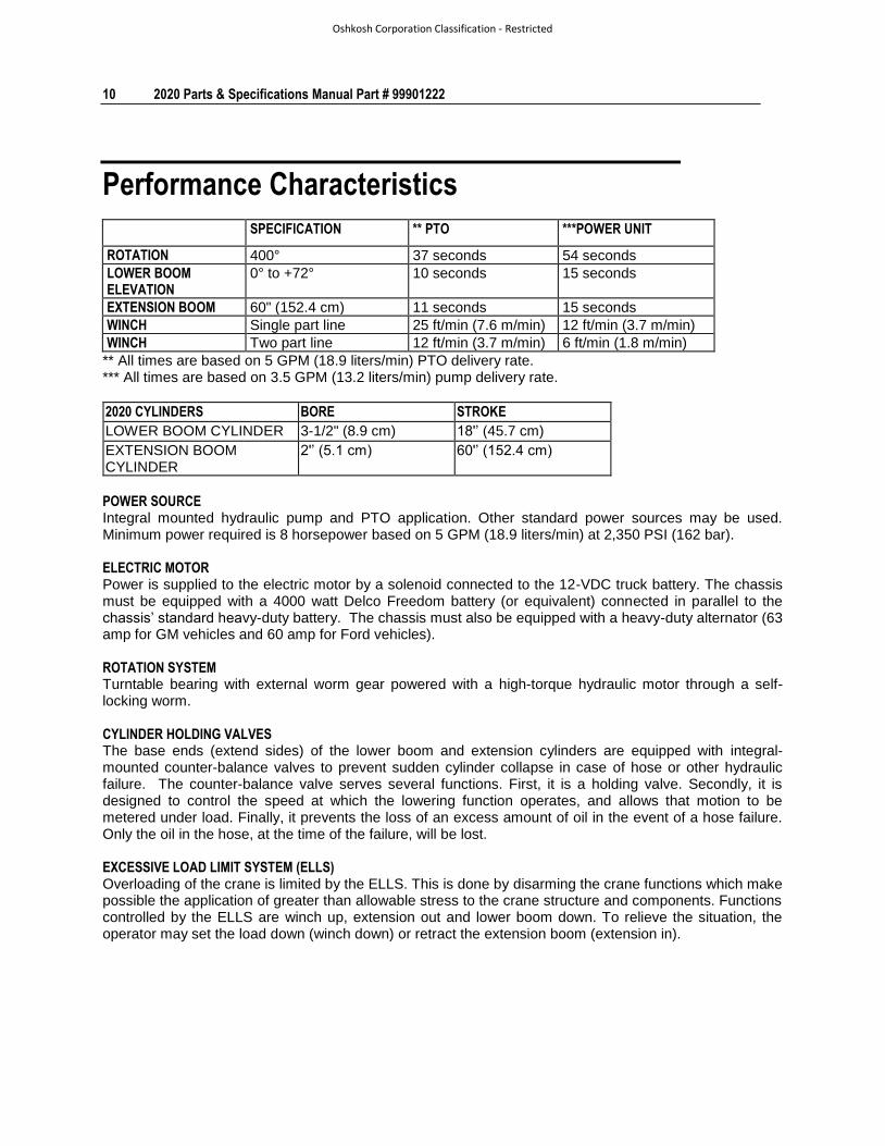
Performance Characteristics
SPECIFICATION ** PTO ***POWER UNIT
ROTATION 400° 37 seconds 54 seconds
LOWER BOOM ELEVATION
0° to +72° 10 seconds 15 seconds
EXTENSION BOOM 60" (152.4 cm) 11 seconds 15 seconds
WINCH Single part line 25 ft/min (7.6 m/min) 12 ft/min (3.7 m/min)
WINCH Two part line 12 ft/min (3.7 m/min) 6 ft/min (1.8 m/min)
** All times are based on 5 GPM (18.9 liters/min) PTO delivery rate. *** All times are based on 3.5 GPM (13.2 liters/min) pump delivery rate.
2020 CYLINDERS BORE STROKE
LOWER BOOM CYLINDER 3-1/2" (8.9 cm) 18'’ (45.7 cm)
EXTENSION BOOM CYLINDER
2'’ (5.1 cm) 60'’ (152.4 cm)
POWER SOURCE Integral mounted hydraulic pump and PTO application. Other standard power sources may be used. Minimum power required is 8 horsepower based on 5 GPM (18.9 liters/min) at 2,350 PSI (162 bar). ELECTRIC MOTOR Power is supplied to the electric motor by a solenoid connected to the 12-VDC truck battery. The chassis must be equipped with a 4000 watt Delco Freedom battery (or equivalent) connected in parallel to the chassis’ standard heavy-duty battery. The chassis must also be equipped with a heavy-duty alternator (63 amp for GM vehicles and 60 amp for Ford vehicles). ROTATION SYSTEM Turntable bearing with external worm gear powered with a high-torque hydraulic motor through a self-locking worm. CYLINDER HOLDING VALVES The base ends (extend sides) of the lower boom and extension cylinders are equipped with integral-mounted counter-balance valves to prevent sudden cylinder collapse in case of hose or other hydraulic failure. The counter-balance valve serves several functions. First, it is a holding valve. Secondly, it is designed to control the speed at which the lowering function operates, and allows that motion to be metered under load. Finally, it prevents the loss of an excess amount of oil in the event of a hose failure. Only the oil in the hose, at the time of the failure, will be lost. EXCESSIVE LOAD LIMIT SYSTEM (ELLS) Overloading of the crane is limited by the ELLS. This is done by disarming the crane functions which make possible the application of greater than allowable stress to the crane structure and components. Functions controlled by the ELLS are winch up, extension out and lower boom down. To relieve the situation, the operator may set the load down (winch down) or retract the extension boom (extension in).
Chapter 2 Specifications 11
Oshkosh Corporation Classification - Restricted
WINCH The winch is powered by a hydraulic motor through a 38:1 ratio worm-gear drive which also functions as a brake. Line speed is 25 ft/min (7.6 m/min) at optimum oil flow of 5 GPM (18.0 liters/min) for 1-part line and 12 ft/min (3.8 m/min) for 2-part line. The maximum single-line capacity of the winch is 2500 lb (1134 kg). The winch is equipped with 65 feet (19.81 m) of 5/16" (0.79 cm) 6 x 25 FW PRF RRL IWRC IPS wire rope. A nylon sheave riding on a lubricated needle bearing is located at the tip of the extension boom. The ratio of winch drum and sheave pitch diameter to wire rope diameter is 18:1. An anti-two block device is included to prevent the lower block or hook assembly from coming in contact with the boom sheave assembly. HYDRAULIC SYSTEM (PTO DRIVEN) Open-centered, full-pressure system that requires 5 GPM (18.9 liters/min) optimum oil flow at 2300 PSI (159 bar). The control valve bank is a 4-spool, stack-type, electric remote-control valve with 30' (9.14 m) control cable. The system includes separate oil reservoir, suction-line strainer, control valve, and return-line filter. ELECTRO-HYDRAULIC SYSTEM (2-SPEED / AUTO-SHIFT) Open-centered, full-pressure system that features a 2-stage hydraulic pump, with the first stage delivering 1.5 GPM (5.7 liter/min) and the second stage delivering 3.5 GPM (13.2 liters/min) at 2300 PSI (159 bar). The operation of the circuit automatically shifts from high to low speed when the crane reaches a certain pressure or load level. The control valve bank is a 4-spool, stack type, 12VDC valve system. The system includes a 5 gallon (18.9 liter) hydraulic reservoir, 10-micron spin-on-type return filter, a hydraulic pump driven by an enclosed, fan-cooled 12VDC motor and all necessary hoses and fittings. MINIMUM CHASSIS SPECIFICATIONS
BODY STYLE Conventional Cab
FRAME SECTION MODULUS 8.0 cubic inches (131.12 cc)
*RBM 290,000 in-lb (3342 kg-meter)
GVWR 15,000 lb (6803 kg)
In addition to these specifications, a heavy-duty battery and alternator are required. It is recommended that the vehicle have power steering and dual rear wheels.
12 2020 Parts & Specifications Manual Part # 99901222
Oshkosh Corporation Classification - Restricted
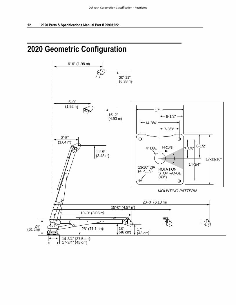
2020 Geometric Configuration
24"(61 cm)
14-3/4" (37.5 cm)17-3/4" (45 cm)
28" (71.1 cm) 18"(46 cm)
17"(43 cm)
10'-0" (3.05 m)
15'-0" (4.57 m)
20'-0" (6.10 m)
6'-6" (1.98 m)
20'-11"(6.38 m)
16'-2"(4.93 m)
11'-5"(3.48 m)
5'-0"
(1.52 m)
3'-5"
(1.04 m)
MOUNTING PATTERN
13/16" DIA.(4 PLCS)
4" DIA. FRONT
ROTATIONSTOP RANGE(40°)
14-3/4"
14-3/4"
8-1/2"
7-3/8"
17"
8-1/2"7-3/8"
17-11/16"
Chapter 2 Specifications 13
Oshkosh Corporation Classification - Restricted
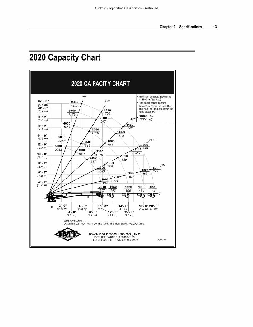
2020 Capacity Chart
70395497
IOWA MOLD TOOLING CO., INC.
TEL: 641-923-3711 FAX: 641-923-2424BOX 189, GARNER, IA 50438-0189
The weight of load-handling devices is part of the load-lifted and must be deducted from the rated capacity.
Maximum one-part line weight is 2500 lb.(1134 kg).
xxxx lb.xxxx kg•
•
•

15
In This Chapter
Crane Assemblies & Grease Zerks........................................... 15 2020 Recommended Spare Parts List ...................................... 16 Crane Installation ..................................................................... 18 Telescopic Crane Orientation ................................................... 20 Electric Remote Handle Operating Instructions ........................ 21 Remote Engine Speed Control (From Crane) ........................... 22
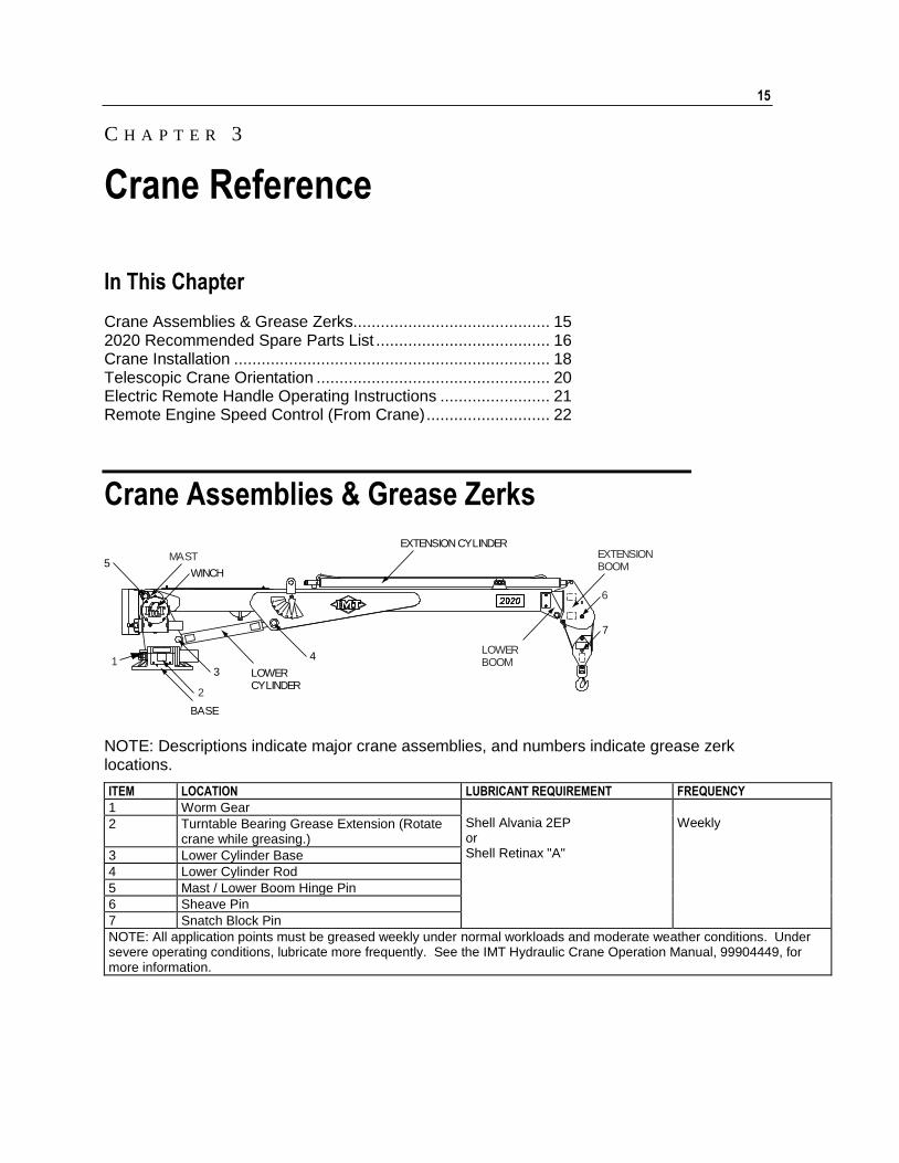
Crane Assemblies & Grease Zerks
MAST
BASE
LOWERBOOM
EXTENSIONBOOM
LOWERCYLINDER
EXTENSION CYLINDER
WINCH
1
2
3
4
5
6
7
NOTE: Descriptions indicate major crane assemblies, and numbers indicate grease zerk locations.
ITEM LOCATION LUBRICANT REQUIREMENT FREQUENCY
1 Worm Gear Shell Alvania 2EP or Shell Retinax "A"
Weekly 2 Turntable Bearing Grease Extension (Rotate
crane while greasing.)
3 Lower Cylinder Base
4 Lower Cylinder Rod
5 Mast / Lower Boom Hinge Pin
6 Sheave Pin
7 Snatch Block Pin
NOTE: All application points must be greased weekly under normal workloads and moderate weather conditions. Under severe operating conditions, lubricate more frequently. See the IMT Hydraulic Crane Operation Manual, 99904449, for more information.
C H A P T E R 3
Crane Reference
16 2020 Parts & Specifications Manual Part # 99901222
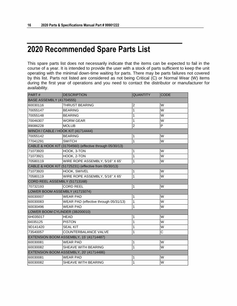
2020 Recommended Spare Parts List
This spare parts list does not necessarily indicate that the items can be expected to fail in the course of a year. It is intended to provide the user with a stock of parts sufficient to keep the unit operating with the minimal down-time waiting for parts. There may be parts failures not covered by this list. Parts not listed are considered as not being Critical (C) or Normal Wear (W) items during the first year of operations and you need to contact the distributor or manufacturer for availability.
PART # DESCRIPTION QUANTITY CODE
BASE ASSEMBLY (41704555)
60030116 THRUST BEARING 2 W
70055147 BEARING 1 W
70055148 BEARING 1 W
70046307 WORM GEAR 1 W
89086228 MOLUB 2 P
WINCH / CABLE / HOOK KIT (41714444)
70055142 BEARING 1 W
77041291 SWITCH 1 W
CABLE & HOOK KIT (31704560) (effective through 05/30/13)
71073920 HOOK, 3-TON 1 W
71073921 HOOK, 2-TON 1 W
70580119 WIRE ROPE ASSEMBLY, 5/16" X 65' 1 W
CABLE & HOOK KIT (51725231) (effective from 05/30/13)
71073920 HOOK, SWIVEL 1 W
70580119 WIRE ROPE ASSEMBLY, 5/16" X 65' 1 W
CORD REEL ASSEMBLY (51713168)
70732193 CORD REEL 1 W
LOWER BOOM ASSEMBLY (41715074)
60030007 WEAR PAD 1 W
60030083 WEAR PAD (effective through 05/31/13) 1 W
60030496 WEAR PAD 1 W
LOWER BOOM CYLINDER (3B200010)
6H035017 HEAD 1 W
6I035125 PISTON 1 W
9D141420 SEAL KIT 1 W
73540057 COUNTERBALANCE VALVE 1 C
EXTENSION BOOM ASSEMBLY, 15' (41714487)
60030081 WEAR PAD 1 W
60030082 SHEAVE WITH BEARING 1 W
EXTENSION BOOM ASSEMBLY, 20' (41714486)
60030081 WEAR PAD 1 W
60030082 SHEAVE WITH BEARING 1 W
Chapter 3 Crane Reference 17
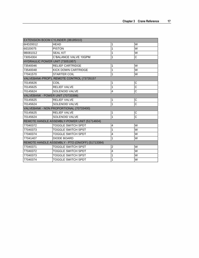
EXTENSION BOOM CYLINDER (3B185010)
6HD20012 HEAD 1 W
6ID20075 PISTON 1 W
9B081012 SEAL KIT 1 W
73054304 C’BALANCE VALVE 10GPM 1 C
HYDRAULIC POWER UNIT (73051957)
73540046 RELIEF CARTRIDGE 1 W
73540048 KICK DOWN CARTRIDGE 1 W
77041570 STARTER COIL 1 W
VALVEBANK-PROP’L REMOTE CONTROL (73735157
70145626 COIL 1 C
70145625 RELIEF VALVE 1 C
70145624 SOLENOID VALVE 4 C
VALVEBANK - POWER UNIT (70733398)
70145625 RELIEF VALVE 1 C
70145624 SOLENOID VALVE 1 C
VALVEBANK - NON PROPORTIONAL (70733400)
70145625 RELIEF VALVE 1 C
70145624 SOLENOID VALVE 1 C
REMOTE HANDLE ASSEMBLY-POWER UNIT (51714604)
77040372 TOGGLE SWITCH SPDT 4 W
77040373 TOGGLE SWITCH SPST 1 W
77040374 TOGGLE SWITCH SPDT 4 W
77041407 DIODE BOARD 1 W
REMOTE HANDLE ASSEMBLY - PTO (ON/OFF) (51713384)
77040371 TOGGLE SWITCH SPST 2 W
77040372 TOGGLE SWITCH SPDT 4 W
77040373 TOGGLE SWITCH SPST 1 W
77040374 TOGGLE SWITCH SPDT 1 W
18 2020 Parts & Specifications Manual Part # 99901222
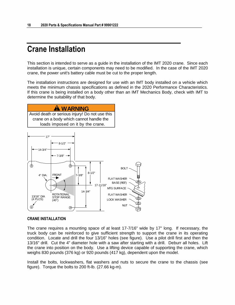
Crane Installation
This section is intended to serve as a guide in the installation of the IMT 2020 crane. Since each installation is unique, certain components may need to be modified. In the case of the IMT 2020 crane, the power unit's battery cable must be cut to the proper length.
The installation instructions are designed for use with an IMT body installed on a vehicle which meets the minimum chassis specifications as defined in the 2020 Performance Characteristics. If this crane is being installed on a body other than an IMT Mechanics Body, check with IMT to determine the suitability of that body.
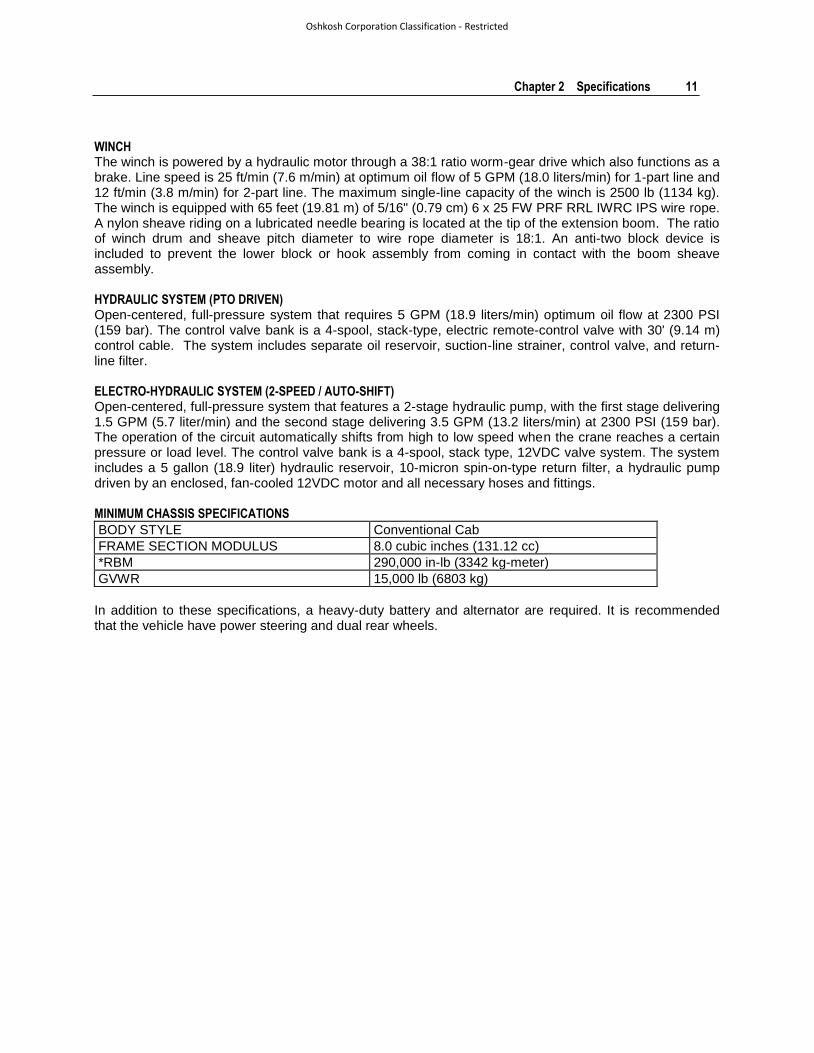
WARNINGAvoid death or serious injury! Do not use this
crane on a body which cannot handle the
loads imposed on it by the crane.
17"
8-1/2"
14-3/4"
7-3/8"
4" DIA.
13/16" DIA(4 PLCS)
ROTATIONALSTOP RANGE(40°)
7-3/8"
14-3/4"
8-1/2"
17-11/16"
FRONT
BOLT
FLAT WASHER
BASE (REF)
MTG SURFACE
FLAT WASHER
LOCK WASHER
NUT
CRANE INSTALLATION
The crane requires a mounting space of at least 17-7/16" wide by 17" long. If necessary, the truck body can be reinforced to give sufficient strength to support the crane in its operating condition. Locate and drill the four 13/16" holes (see figure). Use a pilot drill first and then the 13/16" drill. Cut the 4" diameter hole with a saw after starting with a drill. Deburr all holes. Lift the crane into position on the body. Use a lifting device capable of supporting the crane, which weighs 830 pounds (376 kg) or 920 pounds (417 kg), dependent upon the model.
Install the bolts, lockwashers, flat washers and nuts to secure the crane to the chassis (see figure). Torque the bolts to 200 ft-lb. (27.66 kg-m).
Chapter 3 Crane Reference 19
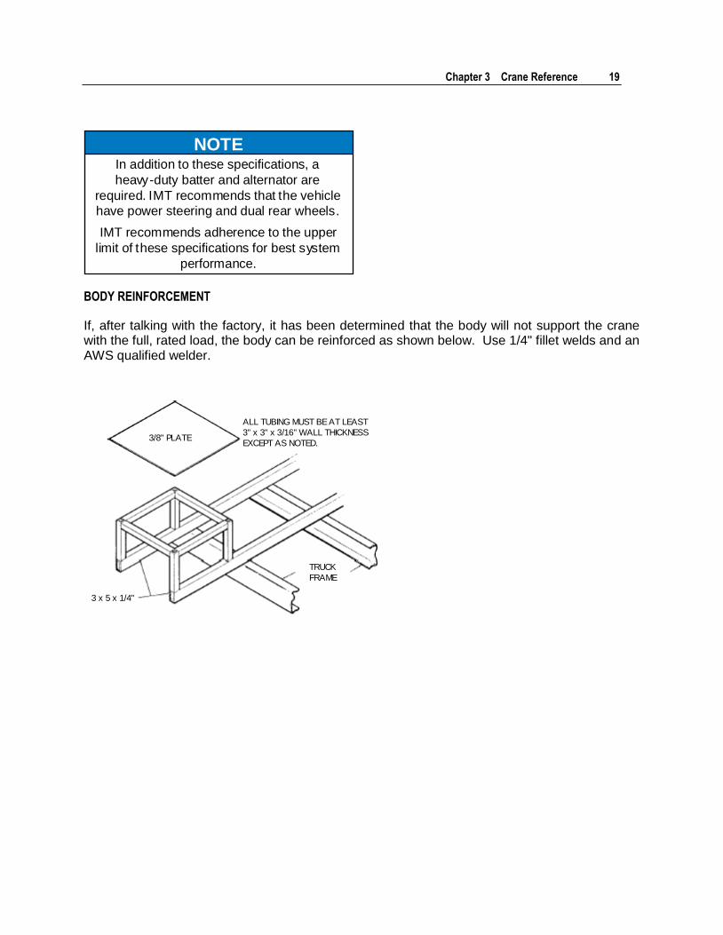
NOTEIn addition to these specifications, a
heavy-duty batter and alternator are
required. IMT recommends that the vehicle
have power steering and dual rear wheels.
IMT recommends adherence to the upper
limit of these specifications for best system
performance.
BODY REINFORCEMENT
If, after talking with the factory, it has been determined that the body will not support the crane with the full, rated load, the body can be reinforced as shown below. Use 1/4" fillet welds and an AWS qualified welder.
TRUCK
FRAME
3 x 5 x 1/4"
3/8" PLATE
ALL TUBING MUST BE AT LEAST
3" x 3" x 3/16" WALL THICKNESS
EXCEPT AS NOTED.
20 2020 Parts & Specifications Manual Part # 99901222
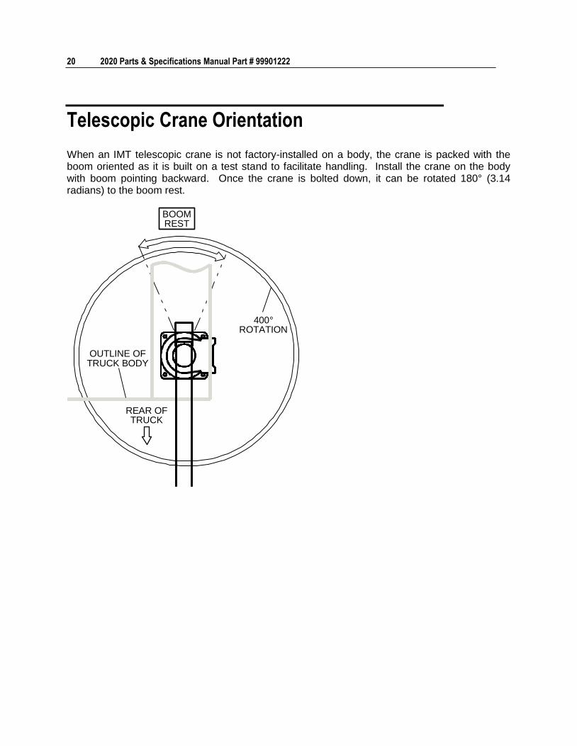
Telescopic Crane Orientation
When an IMT telescopic crane is not factory-installed on a body, the crane is packed with the boom oriented as it is built on a test stand to facilitate handling. Install the crane on the body with boom pointing backward. Once the crane is bolted down, it can be rotated 180° (3.14 radians) to the boom rest.
400°ROTATION
OUTLINE OFTRUCK BODY
REAR OFTRUCK
BOOMREST
Chapter 3 Crane Reference 21
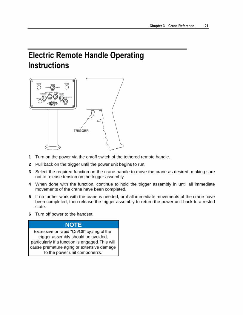
Electric Remote Handle Operating Instructions
ENGINESTOP
ENGINESTARTPOWER
CPRSR CRANE
OFF
OPTION
ROTATIONCCW
CW
EXTENSIONIN
OUT
WINCHDOWN
UP
LOWERDOWN
UP
ENGINE SPDFAST
IDLE
TRIGGER
1 Turn on the power via the on/off switch of the tethered remote handle.
2 Pull back on the trigger until the power unit begins to run.
3 Select the required function on the crane handle to move the crane as desired, making sure not to release tension on the trigger assembly.
4 When done with the function, continue to hold the trigger assembly in until all immediate movements of the crane have been completed.
5 If no further work with the crane is needed, or if all immediate movements of the crane have been completed, then release the trigger assembly to return the power unit back to a rested state.
6 Turn off power to the handset.
NOTEExcessive or rapid “On/Off” cycling of the
trigger assembly should be avoided,
particularly if a function is engaged. This will
cause premature aging or extensive damage
to the power unit components.
22 2020 Parts & Specifications Manual Part # 99901222
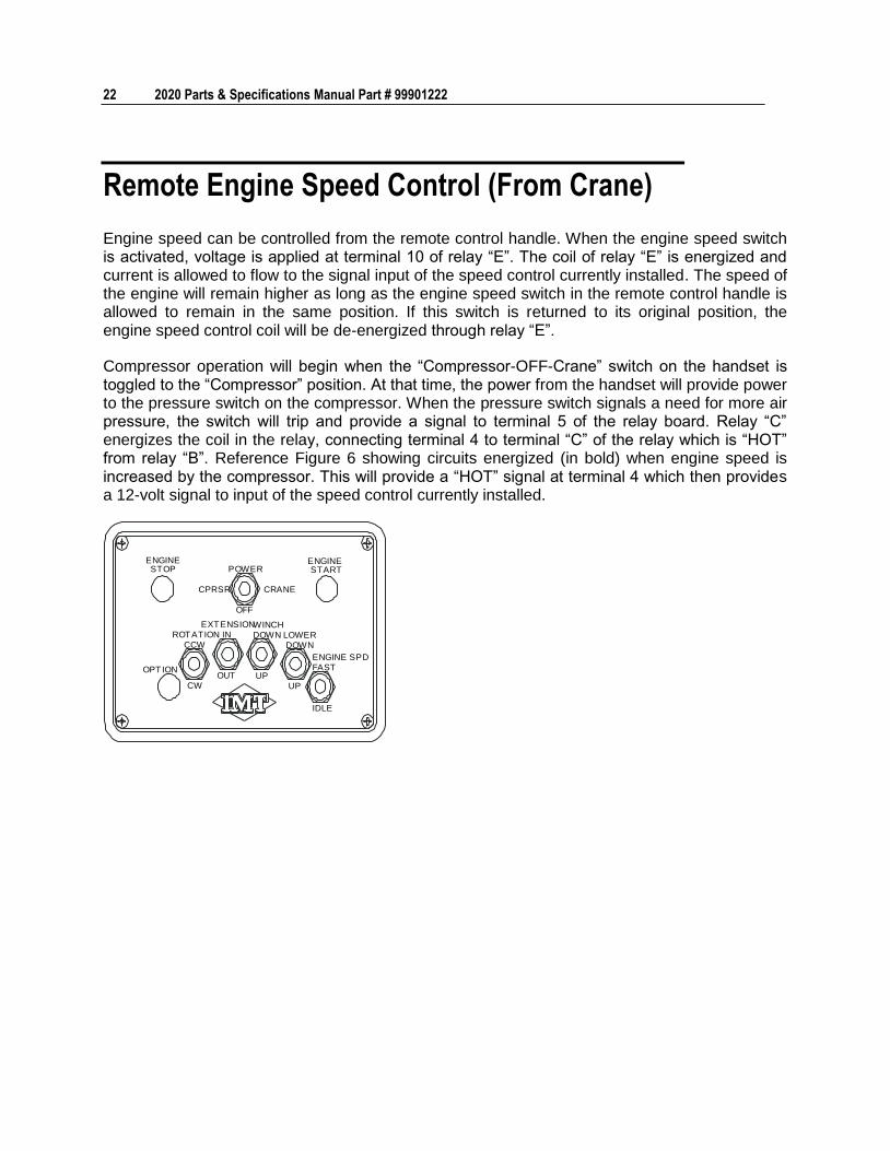
Remote Engine Speed Control (From Crane)
Engine speed can be controlled from the remote control handle. When the engine speed switch is activated, voltage is applied at terminal 10 of relay “E”. The coil of relay “E” is energized and current is allowed to flow to the signal input of the speed control currently installed. The speed of the engine will remain higher as long as the engine speed switch in the remote control handle is allowed to remain in the same position. If this switch is returned to its original position, the engine speed control coil will be de-energized through relay “E”.
Compressor operation will begin when the “Compressor-OFF-Crane” switch on the handset is toggled to the “Compressor” position. At that time, the power from the handset will provide power to the pressure switch on the compressor. When the pressure switch signals a need for more air pressure, the switch will trip and provide a signal to terminal 5 of the relay board. Relay “C” energizes the coil in the relay, connecting terminal 4 to terminal “C” of the relay which is “HOT” from relay “B”. Reference Figure 6 showing circuits energized (in bold) when engine speed is increased by the compressor. This will provide a “HOT” signal at terminal 4 which then provides a 12-volt signal to input of the speed control currently installed.
ENGINESTOP
ENGINESTARTPOWER
CPRSR CRANE
OFF
OPTION
ROTATIONCCW
CW
EXTENSIONIN
OUT
WINCHDOWN
UP
LOWER DOWN
UP
ENGINE SPDFAST
IDLE
23
In This Chapter
Parts Information ...................................................................... 24 Base & Mast Assemblies .......................................................... 26 Boom Assemblies & Cylinders .................................................. 30 Controls & Hydraulics, Power Unit ............................................ 64 Controls & Hydraulics, PTO ...................................................... 76 Controls & Hydraulics, Radio Remote ...................................... 101 Stabilizers................................................................................. 108 Miscellaneous .......................................................................... 109
C H A P T E R 4
Parts
24 2020 Parts & Specifications Manual Part # 99901222
Parts Information
GENERAL
This section contains the exploded parts drawings and accompanying parts lists for the assemblies used on this crane. These drawings are intended to be used in conjunction with the instructions found in the maintenance and repair manuals for this crane family. For optional equipment such as winches and remote controls, refer to the appropriate service manual.
WARNINGDo not attempt to repair any component
without reading the information contained in
the repair section. Pay particular attention to
statements marked Warning, Caution or
Note in that section. Failure to comply with
these instructions may result in damage to
the equipment, personal injury or death.
CRANE IDENTIFICATION
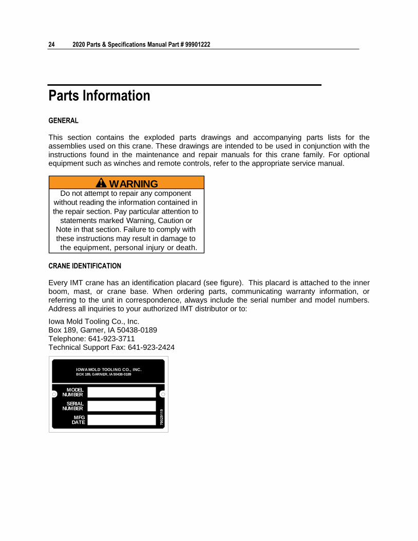
Every IMT crane has an identification placard (see figure). This placard is attached to the inner boom, mast, or crane base. When ordering parts, communicating warranty information, or referring to the unit in correspondence, always include the serial number and model numbers. Address all inquiries to your authorized IMT distributor or to:
Iowa Mold Tooling Co., Inc. Box 189, Garner, IA 50438-0189 Telephone: 641-923-3711 Technical Support Fax: 641-923-2424
MODELNUMBER
SERIALNUMBER
MFGDATE
IOWA MOLD TOOLING CO., INC.BOX 189, GARNER, IA 50438-0189
Chapter 4 Parts 25
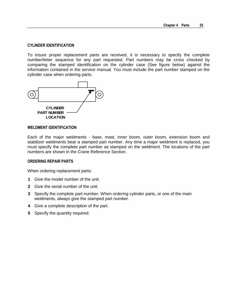
CYLINDER IDENTIFICATION
To insure proper replacement parts are received, it is necessary to specify the complete number/letter sequence for any part requested. Part numbers may be cross checked by comparing the stamped identification on the cylinder case (See figure below) against the information contained in the service manual. You must include the part number stamped on the cylinder case when ordering parts.
CYLINDER
PART NUMBER
LOCATION
WELDMENT IDENTIFICATION
Each of the major weldments - base, mast, inner boom, outer boom, extension boom and stabilizer weldments bear a stamped part number. Any time a major weldment is replaced, you must specify the complete part number as stamped on the weldment. The locations of the part numbers are shown in the Crane Reference Section.
ORDERING REPAIR PARTS
When ordering replacement parts:
1 Give the model number of the unit.
2 Give the serial number of the unit.
3 Specify the complete part number. When ordering cylinder parts, or one of the main weldments, always give the stamped part number.
4 Give a complete description of the part.
5 Specify the quantity required.
26 2020 Parts & Specifications Manual Part # 99901222
Base & Mast Assemblies
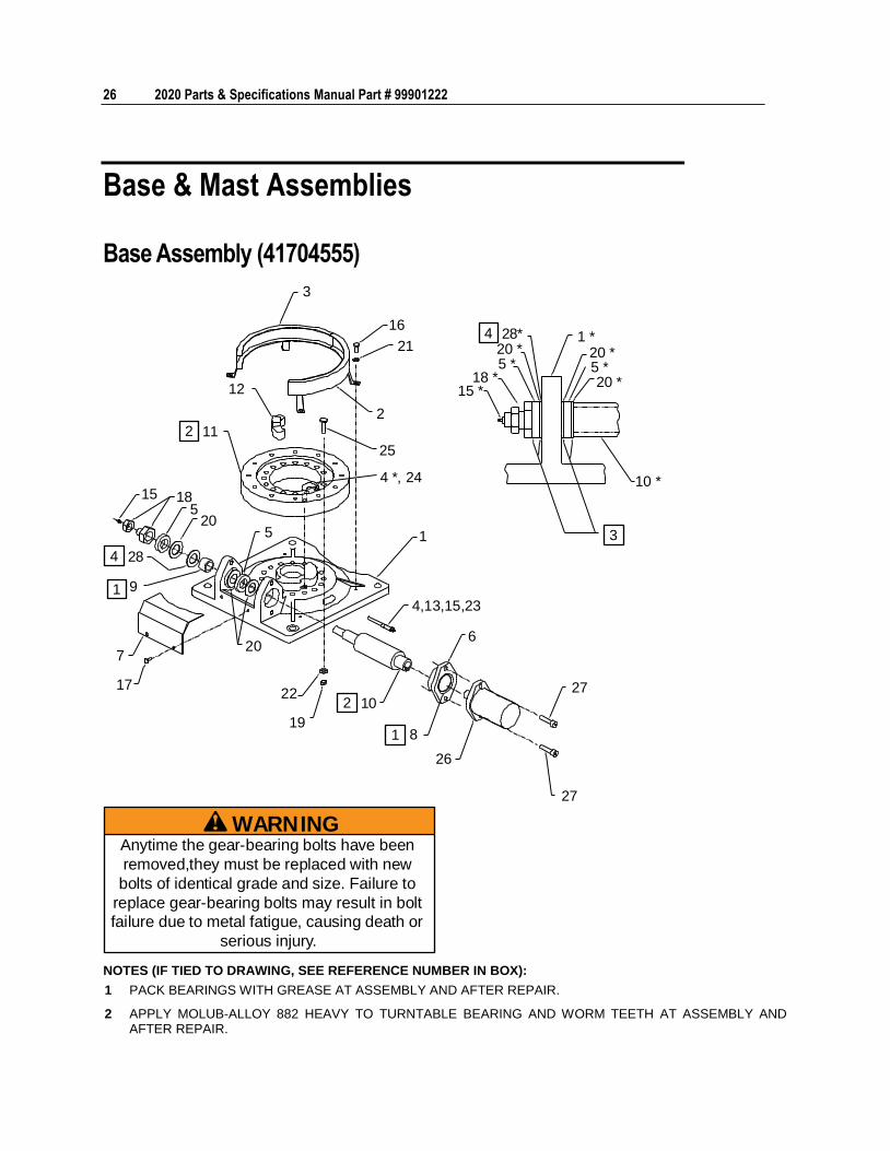
Base Assembly (41704555)
3
16
21
2
25
4 *, 24
12
15 18
205
5 1
9
7
17
20
22
198
26
4,13,15,23
6
27
27
10 *
1 *20 *5 *
18 *15 *
20 *5 *20 *
1
1
2 10
2 11
4 28
4 28*
3
WARNINGAnytime the gear-bearing bolts have been
removed,they must be replaced with new
bolts of identical grade and size. Failure to
replace gear-bearing bolts may result in bolt
failure due to metal fatigue, causing death or
serious injury.
NOTES (IF TIED TO DRAWING, SEE REFERENCE NUMBER IN BOX):
1 PACK BEARINGS WITH GREASE AT ASSEMBLY AND AFTER REPAIR.
2 APPLY MOLUB-ALLOY 882 HEAVY TO TURNTABLE BEARING AND WORM TEETH AT ASSEMBLY AND AFTER REPAIR.
Chapter 4 Parts 27
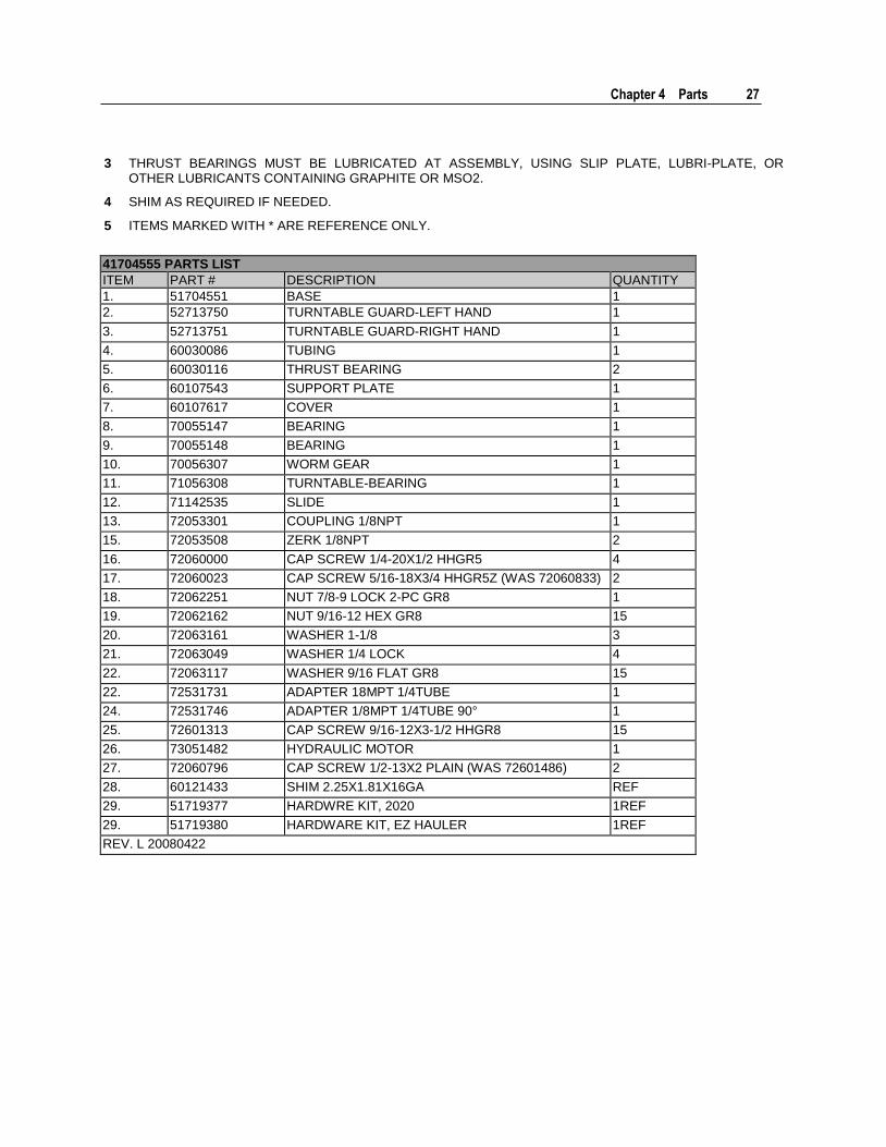
3 THRUST BEARINGS MUST BE LUBRICATED AT ASSEMBLY, USING SLIP PLATE, LUBRI-PLATE, OR OTHER LUBRICANTS CONTAINING GRAPHITE OR MSO2.
4 SHIM AS REQUIRED IF NEEDED.
5 ITEMS MARKED WITH * ARE REFERENCE ONLY.
41704555 PARTS LIST
ITEM PART # DESCRIPTION QUANTITY
1. 51704551 BASE 1
2. 52713750 TURNTABLE GUARD-LEFT HAND 1
3. 52713751 TURNTABLE GUARD-RIGHT HAND 1
4. 60030086 TUBING 1
5. 60030116 THRUST BEARING 2
6. 60107543 SUPPORT PLATE 1
7. 60107617 COVER 1
8. 70055147 BEARING 1
9. 70055148 BEARING 1
10. 70056307 WORM GEAR 1
11. 71056308 TURNTABLE-BEARING 1
12. 71142535 SLIDE 1
13. 72053301 COUPLING 1/8NPT 1
15. 72053508 ZERK 1/8NPT 2
16. 72060000 CAP SCREW 1/4-20X1/2 HHGR5 4
17. 72060023 CAP SCREW 5/16-18X3/4 HHGR5Z (WAS 72060833) 2
18. 72062251 NUT 7/8-9 LOCK 2-PC GR8 1
19. 72062162 NUT 9/16-12 HEX GR8 15
20. 72063161 WASHER 1-1/8 3
21. 72063049 WASHER 1/4 LOCK 4
22. 72063117 WASHER 9/16 FLAT GR8 15
22. 72531731 ADAPTER 18MPT 1/4TUBE 1
24. 72531746 ADAPTER 1/8MPT 1/4TUBE 90° 1
25. 72601313 CAP SCREW 9/16-12X3-1/2 HHGR8 15
26. 73051482 HYDRAULIC MOTOR 1
27. 72060796 CAP SCREW 1/2-13X2 PLAIN (WAS 72601486) 2
28. 60121433 SHIM 2.25X1.81X16GA REF
29. 51719377 HARDWRE KIT, 2020 1REF
29. 51719380 HARDWARE KIT, EZ HAULER 1REF
REV. L 20080422
28 2020 Parts & Specifications Manual Part # 99901222
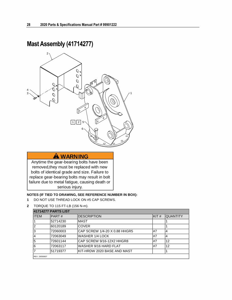
Mast Assembly (41714277)
2
4
3
5
6
1
1 2
WARNINGAnytime the gear-bearing bolts have been
removed,they must be replaced with new
bolts of identical grade and size. Failure to
replace gear-bearing bolts may result in bolt
failure due to metal fatigue, causing death or
serious injury.
NOTES (IF TIED TO DRAWING, SEE REFERENCE NUMBER IN BOX):
1 DO NOT USE THREAD LOCK ON #5 CAP SCREWS.
2 TORQUE TO 115 FT-LB (156 N-m).
41714277 PARTS LIST
ITEM PART # DESCRIPTION KIT # QUANTITY
1 52714230 MAST 1
2 60120189 COVER 1
3 72060003 CAP SCREW 1/4-20 X 0.88 HHGR5 #7 4
4 72063049 WASHER 1/4 LOCK #7 4
5 72601144 CAP SCREW 9/16-12X2 HHGR8 #7 12
6 72063117 WASHER 9/16 HARD FLAT #7 12
7 51719377 KIT-HRDW 2020 BASE AND MAST 1
REV. 20050607
Chapter 4 Parts 29
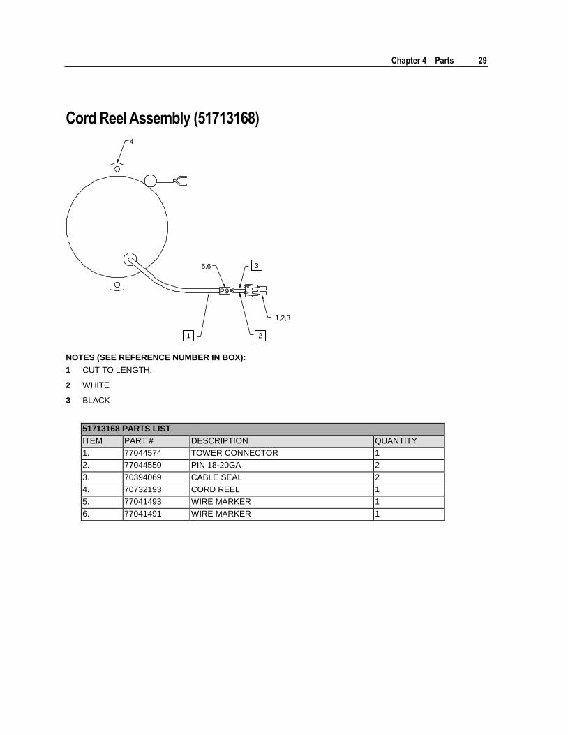
Cord Reel Assembly (51713168)
P9
1,2,3
5,6
4
1 2
3
NOTES (SEE REFERENCE NUMBER IN BOX):
1 CUT TO LENGTH.
2 WHITE
3 BLACK
51713168 PARTS LIST
ITEM PART # DESCRIPTION QUANTITY
1. 77044574 TOWER CONNECTOR 1
2. 77044550 PIN 18-20GA 2
3. 70394069 CABLE SEAL 2
4. 70732193 CORD REEL 1
5. 77041493 WIRE MARKER 1
6. 77041491 WIRE MARKER 1
30 2020 Parts & Specifications Manual Part # 99901222
Boom Assemblies & Cylinders
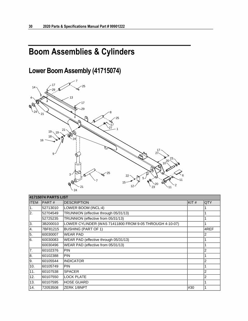
Lower Boom Assembly (41715074)
8
25
1727 1
17
29
13
25
7
1727
2320
10
6
11
211
2023
22
15
12
5
2421
7
253
9
2416
19
18
1921
2124
4
1417
29
41715074 PARTS LIST
ITEM PART # DESCRIPTION KIT # QTY
1. 52713010 LOWER BOOM (INCL:4) 1
2.
52704549 TRUNNION (effective through 05/31/13) 1
52725235 TRUNNION (effective from 05/31/13) 1
3. 3B200010 LOWER CYLINDER (WAS 71411800 FROM 9-05 THROUGH 4-10-07) 1
4. 7BF81215 BUSHING (PART OF 1) 4REF
5. 60030007 WEAR PAD 2
6.
60030083 WEAR PAD (effective through 05/31/13) 1
60030496 WEAR PAD (effective from 05/31/13) 1
7. 60102376 PIN 2
8. 60102388 PIN 1
9. 60105544 INDICATOR 2
10. 60105749 PIN 1
11. 60107538 SPACER 2
12. 60107550 LOCK PLATE 2
13. 60107595 HOSE GUARD 1
14. 72053508 ZERK 1/8NPT #30 1
Chapter 4 Parts 31
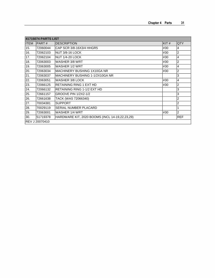
41715074 PARTS LIST
ITEM PART # DESCRIPTION KIT # QTY
15. 72060044 CAP SCR 3/8-16X3/4 HHGR5 #30 4
16. 72062103 NUT 3/8-16 LOCK #30 2
17. 72062104 NUT 1/4-20 LOCK #30 4
18. 72063003 WASHER 3/8 WRT #30 2
19. 72063005 WASHER 1/2 WRT #30 4
20. 72063034 MACHINERY BUSHING 1X10GA NR #30 2
21. 72063037 MACHINERY BUSHING 1-1/2X10GA NR 3
22. 72063051 WASHER 3/8 LOCK #30 4
23. 72066125 RETAINING RING 1 EXT HD #30 2
24. 72066132 RETAINING RING 1-1/2 EXT HD 3
25. 72661157 GROOVE PIN 1/2X2-1/2 3
26. 72661638 TACK (WAS 72066340) 2
27. 70034381 SUPPORT 2
28. 70029119 SERIAL NUMBER PLACARD 1
29. 72063001 WASHER 1/4 WRT #30 2
30. 51719378 HARDWARE KIT, 2020 BOOMS (INCL 14-19,22,23,29) REF
REV J 20070410
32 2020 Parts & Specifications Manual Part # 99901222
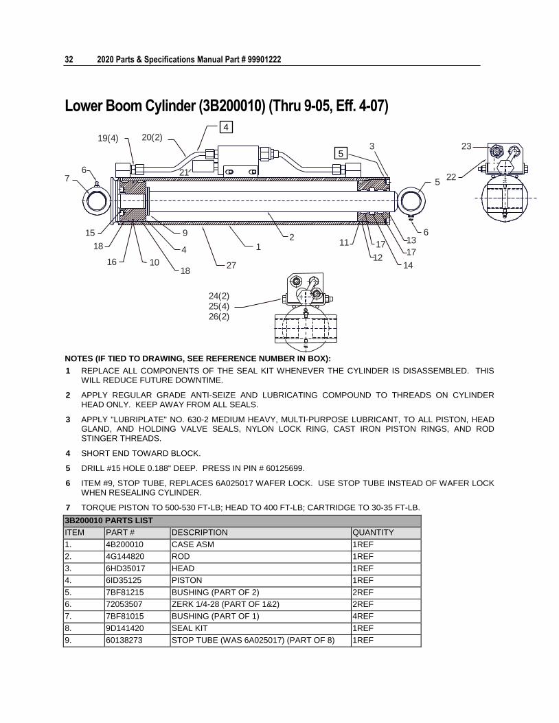
Lower Boom Cylinder (3B200010) (Thru 9-05, Eff. 4-07)
23
22
3
5
613
17
1412
17112
1
27
24(2)25(4)26(2)
9
4
181016
18
15
76
19(4) 20(2)4
5
21
NOTES (IF TIED TO DRAWING, SEE REFERENCE NUMBER IN BOX):
1 REPLACE ALL COMPONENTS OF THE SEAL KIT WHENEVER THE CYLINDER IS DISASSEMBLED. THIS WILL REDUCE FUTURE DOWNTIME.
2 APPLY REGULAR GRADE ANTI-SEIZE AND LUBRICATING COMPOUND TO THREADS ON CYLINDER HEAD ONLY. KEEP AWAY FROM ALL SEALS.
3 APPLY "LUBRIPLATE" NO. 630-2 MEDIUM HEAVY, MULTI-PURPOSE LUBRICANT, TO ALL PISTON, HEAD GLAND, AND HOLDING VALVE SEALS, NYLON LOCK RING, CAST IRON PISTON RINGS, AND ROD STINGER THREADS.
4 SHORT END TOWARD BLOCK.
5 DRILL #15 HOLE 0.188" DEEP. PRESS IN PIN # 60125699.
6 ITEM #9, STOP TUBE, REPLACES 6A025017 WAFER LOCK. USE STOP TUBE INSTEAD OF WAFER LOCK WHEN RESEALING CYLINDER.
7 TORQUE PISTON TO 500-530 FT-LB; HEAD TO 400 FT-LB; CARTRIDGE TO 30-35 FT-LB.
3B200010 PARTS LIST
ITEM PART # DESCRIPTION QUANTITY
1. 4B200010 CASE ASM 1REF
2. 4G144820 ROD 1REF
3. 6HD35017 HEAD 1REF
4. 6ID35125 PISTON 1REF
5. 7BF81215 BUSHING (PART OF 2) 2REF
6. 72053507 ZERK 1/4-28 (PART OF 1&2) 2REF
7. 7BF81015 BUSHING (PART OF 1) 4REF
8. 9D141420 SEAL KIT 1REF
9. 60138273 STOP TUBE (WAS 6A025017) (PART OF 8) 1REF
Chapter 4 Parts 33
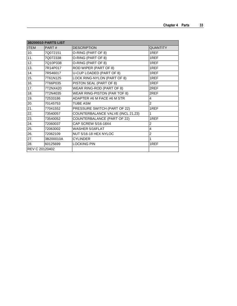
3B200010 PARTS LIST
ITEM PART # DESCRIPTION QUANTITY
10. 7Q072151 O-RING (PART OF 8) 1REF
11. 7Q072338 O-RING (PART OF 8) 1REF
12. 7Q10P338 O-RING (PART OF 8) 1REF
13. 7R14P017 ROD WIPER (PART OF 8) 1REF
14. 7R546017 U-CUP LOADED (PART OF 8) 1REF
15. 7T61N125 LOCK RING-NYLON (PART OF 8) 1REF
16. 7T66P035 PISTON SEAL (PART OF 8) 1REF
17. 7T2NX420 WEAR RING-ROD (PART OF 8) 2REF
18. 7T2N4035 WEAR RING-PISTON (PAR TOF 8) 2REF
19. 72533186 ADAPTER #6 M FACE #6 M STR 4
20. 70145753 TUBE ASM 2
21. 77041552 PRESSURE SWITCH (PART OF 22) 1REF
22. 73540057 COUNTERBALANCE VALVE (INCL 21,23) 1
23. 73540052 COUNTERBALANCE (PART OF 22) 1REF
24. 72060037 CAP SCREW 5/16-18X4 2
25. 72063002 WASHER 5/16FLAT 4
26. 72062109 NUT 5/16-18 HEX NYLOC 2
27. 3B200010A CYLINDER 1
28. 60125699 LOCKING PIN 1REF
REV C 20120402
34 2020 Parts & Specifications Manual Part # 99901222
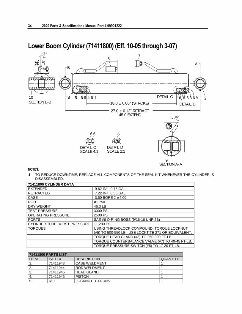
Lower Boom Cylinder (71411800) (Eff. 10-05 through 3-07)
66 66 3 2
78
10
9
5 6 6 4 6 1 DETAIL C
DETAIL D
34°
SECTION A-A
SECTION B-B
13°
66
DETAIL CSCALE 4:1
6
DETAIL DSCALE 2:1
B
B
A
A
18.0 ± 0.06" (STROKE)
27.0 ± 0.12" RETRACT45.0 EXTEND
NOTES:
1 TO REDUCE DOWNTIME, REPLACE ALL COMPONENTS OF THE SEAL KIT WHENEVER THE CYLINDER IS DISASSEMBLED.
71411800 CYLINDER DATA
EXTENDED 9.62 IN², 0.75 GAL
RETRACTED 7.22 IN², 0.56 GAL
CASE 3.50 BORE X ø4.00
ROD ø1.750
DRY WEIGHT 46.3 LB
TEST PRESSURE 3000 PSI
OPERATING PRESSURE 2500 PSI
PORTS SAE #6 O-RING BOSS (9/16-16 UNF-2B)
CYLINDER TUBE BURST PRESSURE 11,280 PSI
TORQUES USING THREADLOCK COMPOUND, TORQUE LOCKNUT (#5) TO 500-550 LB. USE LOCKTITE 271 OR EQUIVALENT.
TORQUE HEAD GLAND (#3) TO 250-300 FT-LB.
TORQUE COUNTERBALANCE VALVE (#7) TO 40-45 FT-LB.
TORQUE PRESSURE SWITCH (#8) TO 17-20 FT-LB.
71411800 PARTS LIST
ITEM PART # DESCRIPTION QUANTITY
1. 71411943 CASE WELDMENT 1
2. 71411944 ROD WELDMENT 1
3. 71411945 HEAD GLAND 1
4. 71411946 PISTON 1
5. REF LOCKNUT, 1-14 UNS 1
Chapter 4 Parts 35
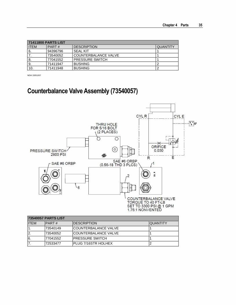
71411800 PARTS LIST
ITEM PART # DESCRIPTION QUANTITY
6. 94396796 SEAL KIT 1
7. 73540052 COUNTERBALANCE VALVE 1
8. 77041552 PRESSURE SWITCH 1
9. 71411947 BUSHING 2
10. 71411948 BUSHING 2
NEW 20051007
Counterbalance Valve Assembly (73540057)
73540057 PARTS LIST
ITEM PART # DESCRIPTION QUANTITY
1. 73540149 COUNTERBALANCE VALVE 1
2. 73540052 COUNTERBALANCE VALVE 1
6. 77041552 PRESSURE SWITCH 1
7. 72533477 PLUG 7/16STR HOLHEX 2
36 2020 Parts & Specifications Manual Part # 99901222
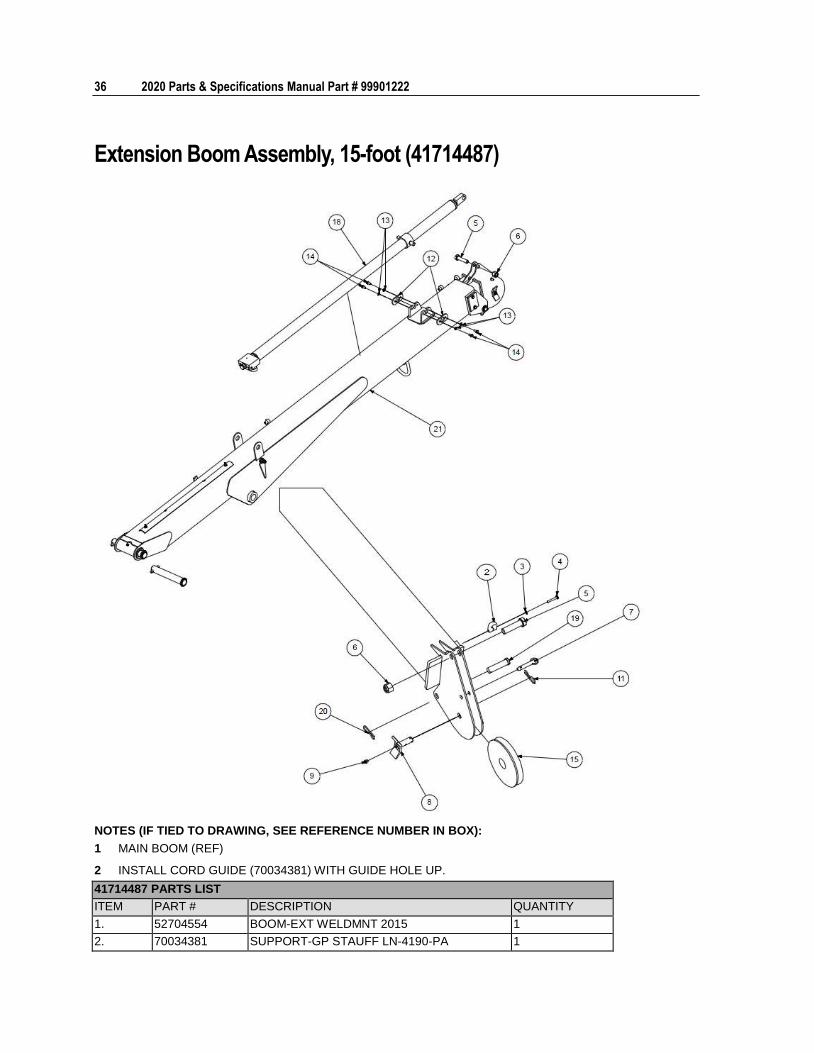
Extension Boom Assembly, 15-foot (41714487)
NOTES (IF TIED TO DRAWING, SEE REFERENCE NUMBER IN BOX):
1 MAIN BOOM (REF)
2 INSTALL CORD GUIDE (70034381) WITH GUIDE HOLE UP.
41714487 PARTS LIST
ITEM PART # DESCRIPTION QUANTITY
1. 52704554 BOOM-EXT WELDMNT 2015 1
2. 70034381 SUPPORT-GP STAUFF LN-4190-PA 1
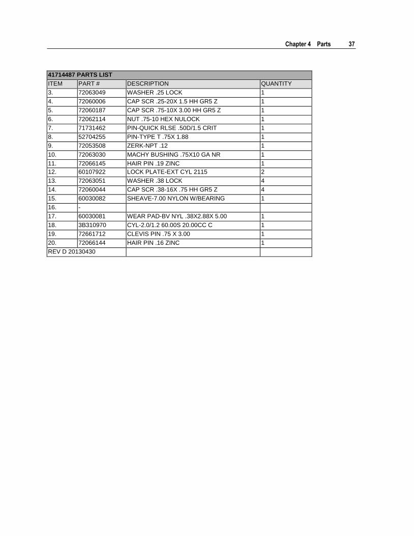
Chapter 4 Parts 37
41714487 PARTS LIST
ITEM PART # DESCRIPTION QUANTITY
3. 72063049 WASHER .25 LOCK 1
4. 72060006 CAP SCR .25-20X 1.5 HH GR5 Z 1
5. 72060187 CAP SCR .75-10X 3.00 HH GR5 Z 1
6. 72062114 NUT .75-10 HEX NULOCK 1
7. 71731462 PIN-QUICK RLSE .50D/1.5 CRIT 1
8. 52704255 PIN-TYPE T .75X 1.88 1
9. 72053508 ZERK-NPT .12 1
10. 72063030 MACHY BUSHING .75X10 GA NR 1
11. 72066145 HAIR PIN .19 ZINC 1
12. 60107922 LOCK PLATE-EXT CYL 2115 2
13. 72063051 WASHER .38 LOCK 4
14. 72060044 CAP SCR .38-16X .75 HH GR5 Z 4
15. 60030082 SHEAVE-7.00 NYLON W/BEARING 1
16. -
17. 60030081 WEAR PAD-BV NYL .38X2.88X 5.00 1
18. 3B310970 CYL-2.0/1.2 60.00S 20.00CC C 1
19. 72661712 CLEVIS PIN .75 X 3.00 1
20. 72066144 HAIR PIN .16 ZINC 1
REV D 20130430
38 2020 Parts & Specifications Manual Part # 99901222
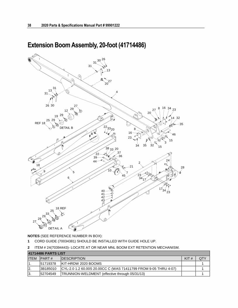
Extension Boom Assembly, 20-foot (41714486)
A
B
263031
31
13
2720
4
2027
8 16 34 23
14 32
35
46
153
15323534
37
16
23
8203322
38 33 20
36
21
745
10
2239
44
5
6
9
18
26 30
3113
31
40414243
18 REF25
3329
2927
DETAIL A
2334
17
1734
23
28
242
REF 1825 29
19 29
1229
27
DETAIL B
NOTES (SEE REFERENCE NUMBER IN BOX):
1 CORD GUIDE (70034381) SHOULD BE INSTALLED WITH GUIDE HOLE UP.
2 ITEM # 24(70394443)- LOCATE AT OR NEAR MNL BOOM EXT RETENTION MECHANISM.
41714486 PARTS LIST
ITEM PART # DESCRIPTION KIT # QTY
1. 51719378 KIT-HRDW 2020 BOOMS 1
2. 3B185010 CYL-2.0 1.2 60.00S 20.00CC C (WAS 71411799 FROM 9-05 THRU 4-07) 1
3. 52704549 TRUNNION-WELDMENT (effective through 05/31/13) 1
Chapter 4 Parts 39
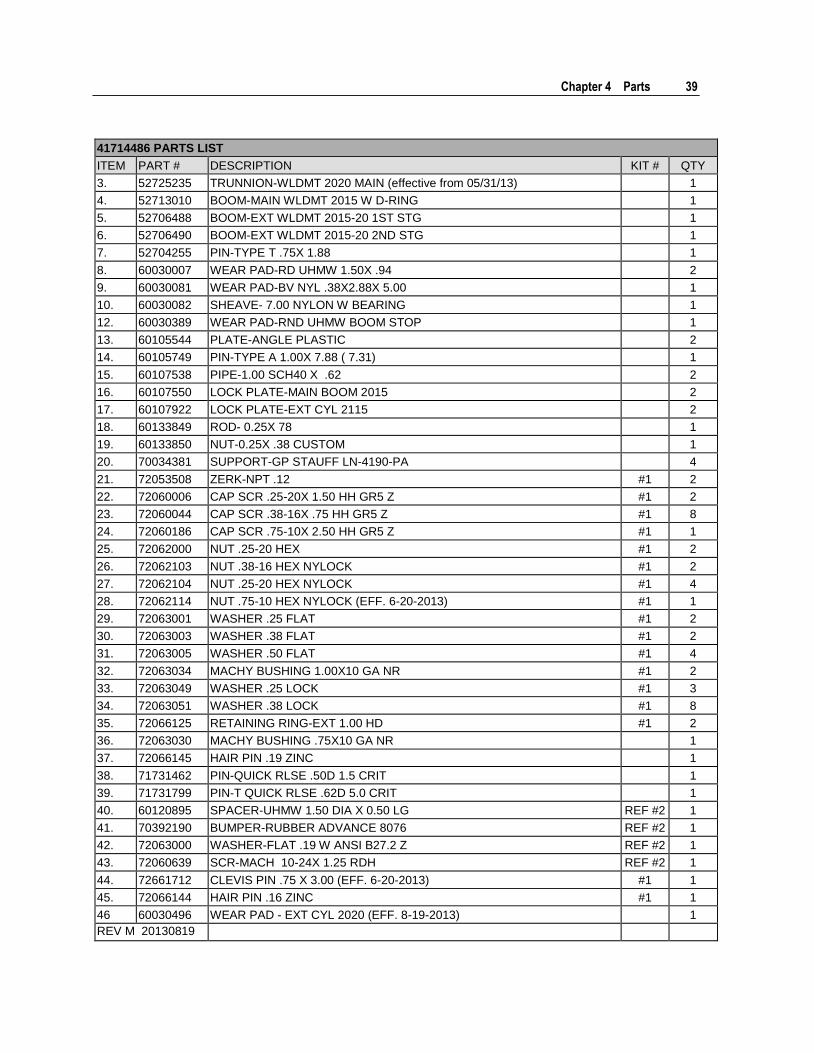
41714486 PARTS LIST
ITEM PART # DESCRIPTION KIT # QTY
3. 52725235 TRUNNION-WLDMT 2020 MAIN (effective from 05/31/13) 1
4. 52713010 BOOM-MAIN WLDMT 2015 W D-RING 1
5. 52706488 BOOM-EXT WLDMT 2015-20 1ST STG 1
6. 52706490 BOOM-EXT WLDMT 2015-20 2ND STG 1
7. 52704255 PIN-TYPE T .75X 1.88 1
8. 60030007 WEAR PAD-RD UHMW 1.50X .94 2
9. 60030081 WEAR PAD-BV NYL .38X2.88X 5.00 1
10. 60030082 SHEAVE- 7.00 NYLON W BEARING 1
12. 60030389 WEAR PAD-RND UHMW BOOM STOP 1
13. 60105544 PLATE-ANGLE PLASTIC 2
14. 60105749 PIN-TYPE A 1.00X 7.88 ( 7.31) 1
15. 60107538 PIPE-1.00 SCH40 X .62 2
16. 60107550 LOCK PLATE-MAIN BOOM 2015 2
17. 60107922 LOCK PLATE-EXT CYL 2115 2
18. 60133849 ROD- 0.25X 78 1
19. 60133850 NUT-0.25X .38 CUSTOM 1
20. 70034381 SUPPORT-GP STAUFF LN-4190-PA 4
21. 72053508 ZERK-NPT .12 #1 2
22. 72060006 CAP SCR .25-20X 1.50 HH GR5 Z #1 2
23. 72060044 CAP SCR .38-16X .75 HH GR5 Z #1 8
24. 72060186 CAP SCR .75-10X 2.50 HH GR5 Z #1 1
25. 72062000 NUT .25-20 HEX #1 2
26. 72062103 NUT .38-16 HEX NYLOCK #1 2
27. 72062104 NUT .25-20 HEX NYLOCK #1 4
28. 72062114 NUT .75-10 HEX NYLOCK (EFF. 6-20-2013) #1 1
29. 72063001 WASHER .25 FLAT #1 2
30. 72063003 WASHER .38 FLAT #1 2
31. 72063005 WASHER .50 FLAT #1 4
32. 72063034 MACHY BUSHING 1.00X10 GA NR #1 2
33. 72063049 WASHER .25 LOCK #1 3
34. 72063051 WASHER .38 LOCK #1 8
35. 72066125 RETAINING RING-EXT 1.00 HD #1 2
36. 72063030 MACHY BUSHING .75X10 GA NR 1
37. 72066145 HAIR PIN .19 ZINC 1
38. 71731462 PIN-QUICK RLSE .50D 1.5 CRIT 1
39. 71731799 PIN-T QUICK RLSE .62D 5.0 CRIT 1
40. 60120895 SPACER-UHMW 1.50 DIA X 0.50 LG REF #2 1
41. 70392190 BUMPER-RUBBER ADVANCE 8076 REF #2 1
42. 72063000 WASHER-FLAT .19 W ANSI B27.2 Z REF #2 1
43. 72060639 SCR-MACH 10-24X 1.25 RDH REF #2 1
44. 72661712 CLEVIS PIN .75 X 3.00 (EFF. 6-20-2013) #1 1
45. 72066144 HAIR PIN .16 ZINC #1 1
46 60030496 WEAR PAD - EXT CYL 2020 (EFF. 8-19-2013) 1
REV M 20130819
40 2020 Parts & Specifications Manual Part # 99901222
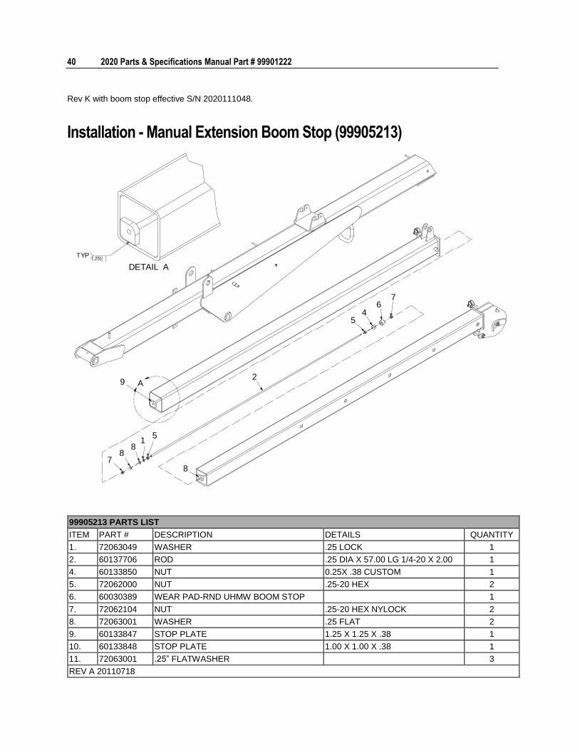
Rev K with boom stop effective S/N 2020111048.
Installation - Manual Extension Boom Stop (99905213)
A
DETAIL A(.25)
TYP
29
78
81
5
8
76
54
99905213 PARTS LIST
ITEM PART # DESCRIPTION DETAILS QUANTITY
1. 72063049 WASHER .25 LOCK 1
2. 60137706 ROD .25 DIA X 57.00 LG 1/4-20 X 2.00 1
4. 60133850 NUT 0.25X .38 CUSTOM 1
5. 72062000 NUT .25-20 HEX 2
6. 60030389 WEAR PAD-RND UHMW BOOM STOP 1
7. 72062104 NUT .25-20 HEX NYLOCK 2
8. 72063001 WASHER .25 FLAT 2
9. 60133847 STOP PLATE 1.25 X 1.25 X .38 1
10. 60133848 STOP PLATE 1.00 X 1.00 X .38 1
11. 72063001 .25” FLATWASHER 3
REV A 20110718
Chapter 4 Parts 41
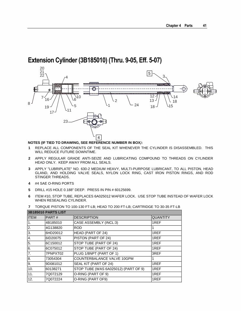
Extension Cylinder (3B185010) (Thru. 9-05, Eff. 5-07)
1
224 18
1213
15
1814
3
23
202122 4
106
511
17
19
168
7
4
5
NOTES (IF TIED TO DRAWING, SEE REFERENCE NUMBER IN BOX):
1 REPLACE ALL COMPONENTS OF THE SEAL KIT WHENEVER THE CYLINDER IS DISASSEMBLED. THIS WILL REDUCE FUTURE DOWNTIME.
2 APPLY REGULAR GRADE ANTI-SEIZE AND LUBRICATING COMPOUND TO THREADS ON CYLINDER HEAD ONLY. KEEP AWAY FROM ALL SEALS.
3 APPLY "LUBRIPLATE" NO. 630-2 MEDIUM HEAVY, MULTI-PURPOSE LUBRICANT, TO ALL PISTON, HEAD GLAND, AND HOLDING VALVE SEALS, NYLON LOCK RING, CAST IRON PISTON RINGS, AND ROD STINGER THREADS.
4 #4 SAE O-RING PORTS
5 DRILL #15 HOLE 0.188" DEEP. PRESS IN PIN # 60125699.
6 ITEM #10, STOP TUBE, REPLACES 6A025012 WAFER LOCK. USE STOP TUBE INSTEAD OF WAFER LOCK WHEN RESEALING CYLINDER.
7 TORQUE PISTON TO 100-130 FT-LB; HEAD TO 200 FT-LB; CARTRIDGE TO 30-35 FT-LB
3B185010 PARTS LIST
ITEM PART # DESCRIPTION QUANTITY
1. 4B185010 CASE ASSEMBLY (INCL:3) 1REF
2. 4G138820 ROD 1
3. 6HD20012 HEAD (PART OF 24) 1REF
4. 6ID20075 PISTON (PART OF 24) 1REF
5. 6C150012 STOP TUBE (PART OF 24) 1REF
6. 6C075012 STOP TUBE (PART OF 24) 1REF
7. 7PNPXT02 PLUG 1/8NPT (PART OF 1) 3REF
8. 73054304 COUNTERBALANCE VALVE 10GPM 1
9. 9D081012 SEAL KIT (PART OF 24) 1REF
10. 60138271 STOP TUBE (WAS 6A025012) (PART OF 9) 1REF
11. 7Q072129 O-RING (PART OF 9) 1REF
12. 7Q072224 O-RING (PART OF9) 1REF
42 2020 Parts & Specifications Manual Part # 99901222
3B185010 PARTS LIST
ITEM PART # DESCRIPTION QUANTITY
13. 7Q10P224 O-RING (PART OF 9) 1REF
14. 7R14P012 ROD WIPER (PART OF 9) 1REF
15. 7R546012 U-CUP LOADED (PART OF 9) 1REF
16. 7T61N075 LOCK RING (PART OF 9) 1REF
17. 7T66P020 PISTON SEAL (PART OF 9) 1REF
18. 7T2NX415 WEAR RING-ROD (PART OF 9) 2REF
19. 7T2N4020 WEAR RING-PISTON (PART OF 9) 1REF
20. 70392190 BUMPER 1
21. 72060639 MACHINERY SCREW #10-24X1-1/4 RDHD 1
22. 72063000 WASHER .19 FLAT 1
23. 60120895 SPACER 1
24. 3B185010A CYLINDER (INCL 1-6, 8,9) 1
25. 60125699 PIN-LOCKING TUBE 1REF
REV D 20120402
Chapter 4 Parts 43
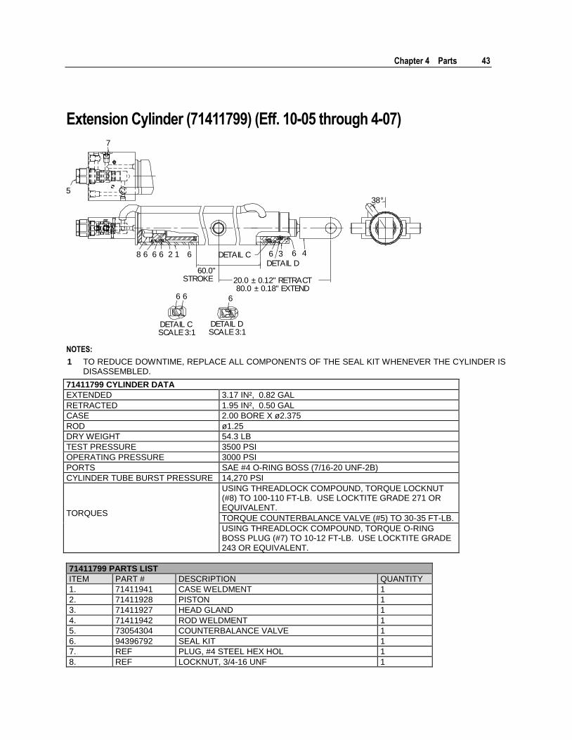
Extension Cylinder (71411799) (Eff. 10-05 through 4-07)
12 3 466668
7
5
6
6 6
6
6
DETAIL CSCALE 3:1
DETAIL DSCALE 3:1
DETAIL CDETAIL D
20.0 ± 0.12" RETRACT80.0 ± 0.18" EXTEND
60.0"STROKE
38°
NOTES:
1 TO REDUCE DOWNTIME, REPLACE ALL COMPONENTS OF THE SEAL KIT WHENEVER THE CYLINDER IS DISASSEMBLED.
71411799 CYLINDER DATA
EXTENDED 3.17 IN², 0.82 GAL
RETRACTED 1.95 IN², 0.50 GAL
CASE 2.00 BORE X ø2.375
ROD ø1.25
DRY WEIGHT 54.3 LB
TEST PRESSURE 3500 PSI
OPERATING PRESSURE 3000 PSI
PORTS SAE #4 O-RING BOSS (7/16-20 UNF-2B)
CYLINDER TUBE BURST PRESSURE 14,270 PSI
TORQUES
USING THREADLOCK COMPOUND, TORQUE LOCKNUT (#8) TO 100-110 FT-LB. USE LOCKTITE GRADE 271 OR EQUIVALENT.
TORQUE COUNTERBALANCE VALVE (#5) TO 30-35 FT-LB.
USING THREADLOCK COMPOUND, TORQUE O-RING BOSS PLUG (#7) TO 10-12 FT-LB. USE LOCKTITE GRADE 243 OR EQUIVALENT.
71411799 PARTS LIST
ITEM PART # DESCRIPTION QUANTITY
1. 71411941 CASE WELDMENT 1
2. 71411928 PISTON 1
3. 71411927 HEAD GLAND 1
4. 71411942 ROD WELDMENT 1
5. 73054304 COUNTERBALANCE VALVE 1
6. 94396792 SEAL KIT 1
7. REF PLUG, #4 STEEL HEX HOL 1
8. REF LOCKNUT, 3/4-16 UNF 1
44
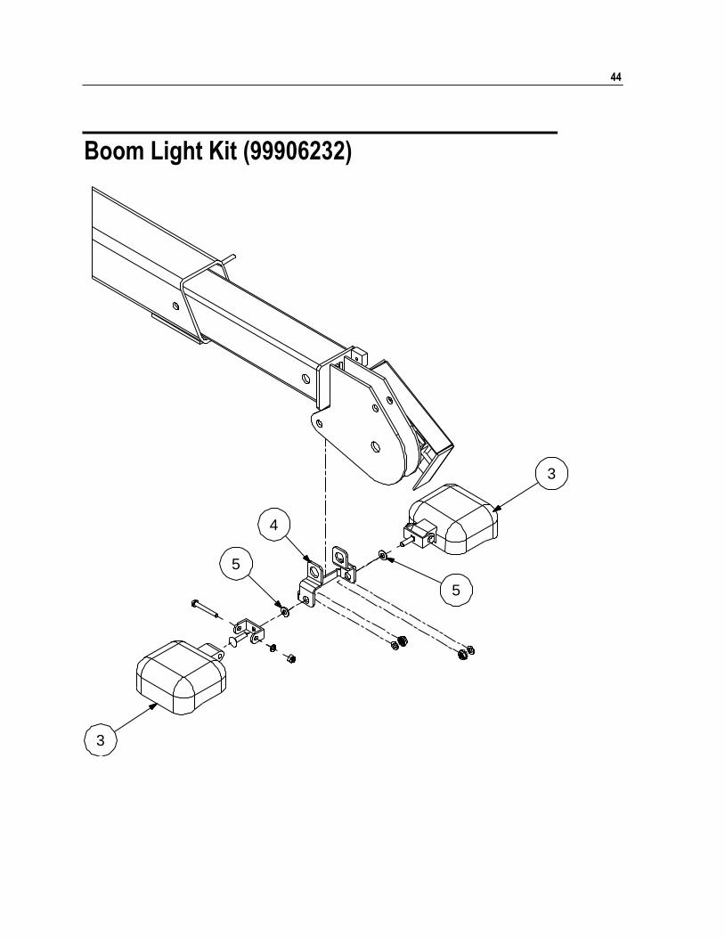
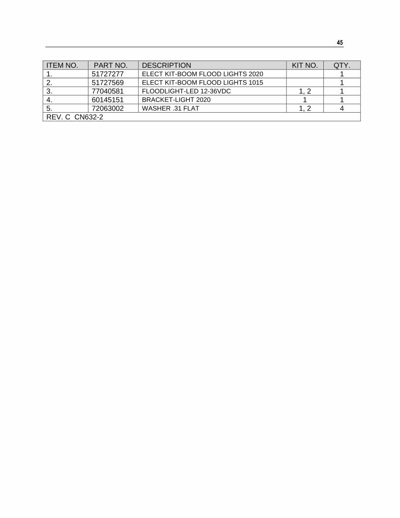
Boom Light Kit (99906232)
3
3
5
4
5
45
ITEM NO. PART NO. DESCRIPTION KIT NO. QTY.
1. 51727277 ELECT KIT-BOOM FLOOD LIGHTS 2020 1
2. 51727569 ELECT KIT-BOOM FLOOD LIGHTS 1015 1
3. 77040581 FLOODLIGHT-LED 12-36VDC 1, 2 1
4. 60145151 BRACKET-LIGHT 2020 1 1
5. 72063002 WASHER .31 FLAT 1, 2 4
REV. C CN632-2
46
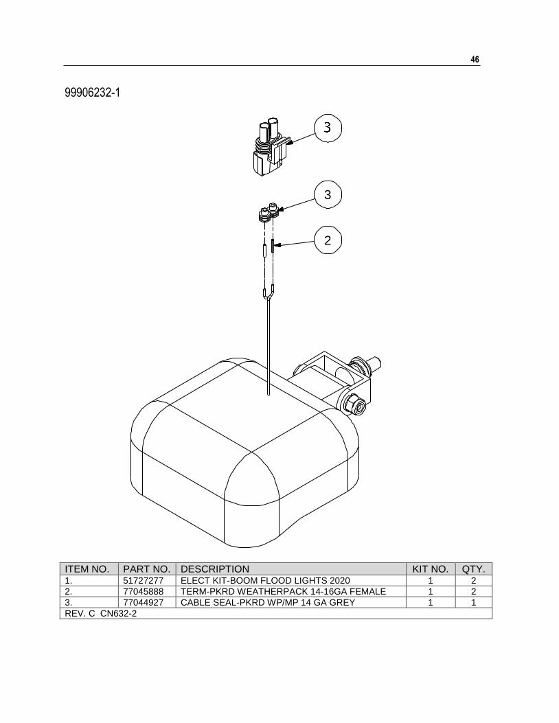
99906232-1
2
3
ITEM NO. PART NO. DESCRIPTION KIT NO. QTY. 1. 51727277 ELECT KIT-BOOM FLOOD LIGHTS 2020 1 2
2. 77045888 TERM-PKRD WEATHERPACK 14-16GA FEMALE 1 2
3. 77044927 CABLE SEAL-PKRD WP/MP 14 GA GREY 1 1
REV. C CN632-2
47
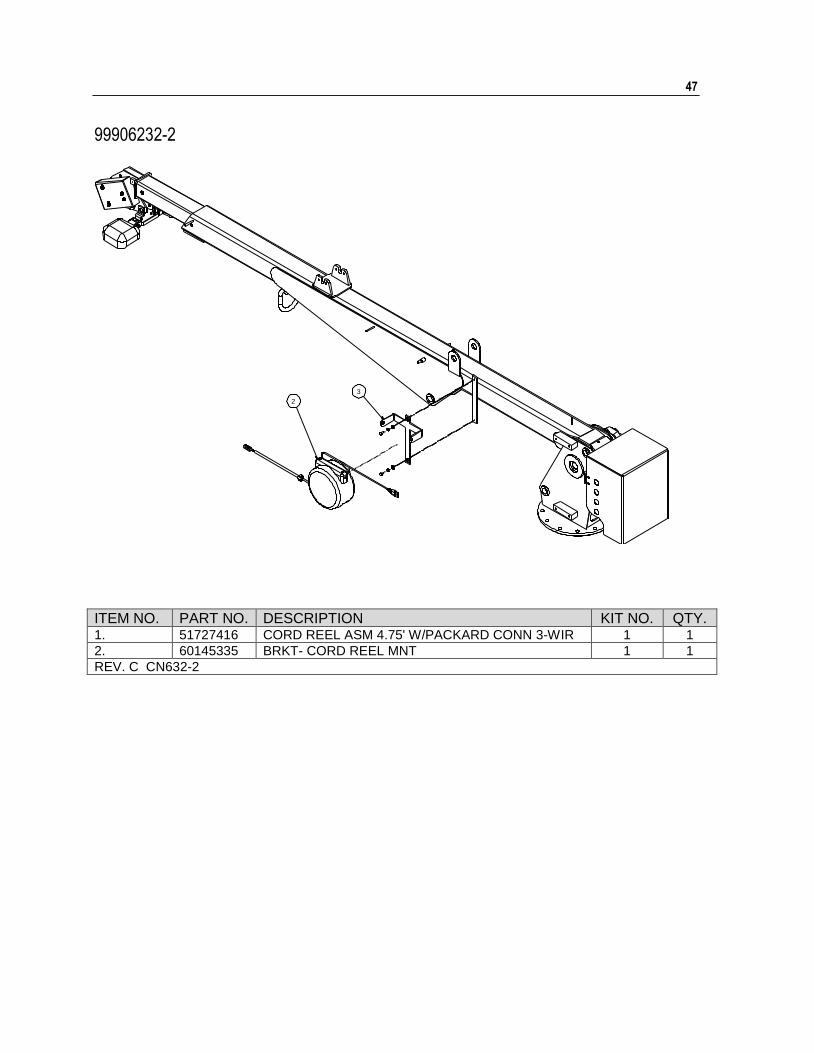
99906232-2
2
3
ITEM NO. PART NO. DESCRIPTION KIT NO. QTY. 1. 51727416 CORD REEL ASM 4.75' W/PACKARD CONN 3-WIR 1 1
2. 60145335 BRKT- CORD REEL MNT 1 1
REV. C CN632-2
48
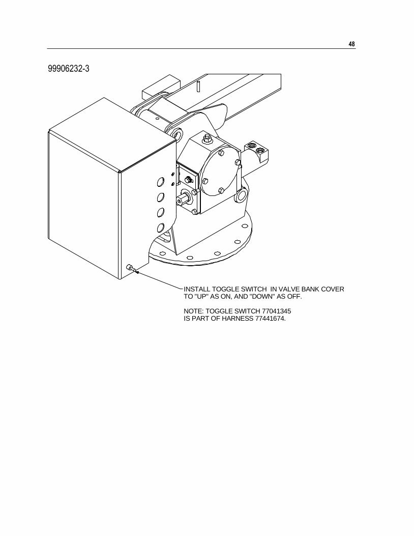
99906232-3
INSTALL TOGGLE SWITCH IN VALVE BANK COVERTO "UP" AS ON, AND "DOWN" AS OFF.
NOTE: TOGGLE SWITCH 77041345IS PART OF HARNESS 77441674.
Chapter 4 Parts 49
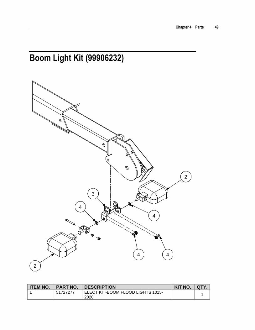
Boom Light Kit (99906232)
2
2
4
3
4
44
ITEM NO. PART NO. DESCRIPTION KIT NO. QTY. 1 51727277 ELECT KIT-BOOM FLOOD LIGHTS 1015-
2020 1

50 2020 Parts & Specifications Manual Part # 99901222
ITEM NO. PART NO. DESCRIPTION KIT NO. QTY. 2 77040581 FLOODLIGHT-LED 12-36VDC 1 2
3 60145151 BRACKET-LIGHT 1015-2020 1 1
4 72063002 WASHER .31 FLAT 1 4
REV. B
Effective 1-1-2018
51
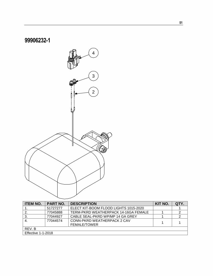
99906232-1
2
3
4
ITEM NO. PART NO. DESCRIPTION KIT NO. QTY. 1. 51727277 ELECT KIT-BOOM FLOOD LIGHTS 1015-2020 1
2. 77045888 TERM-PKRD WEATHERPACK 14-16GA FEMALE 1 2
3. 77044927 CABLE SEAL-PKRD WP/MP 14 GA GREY 1 2
4. 77044574 CONN-PKRD WEATHERPACK 2 CAV FEMALE/TOWER
1 1
REV. B
Effective 1-1-2018
52
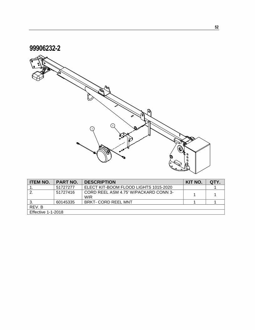
99906232-2
2
3
ITEM NO. PART NO. DESCRIPTION KIT NO. QTY. 1. 51727277 ELECT KIT-BOOM FLOOD LIGHTS 1015-2020 1
2. 51727416 CORD REEL ASM 4.75' W/PACKARD CONN 3-WIR
1 1
3. 60145335 BRKT- CORD REEL MNT 1 1
REV. B
Effective 1-1-2018
Chapter 4 Parts 53
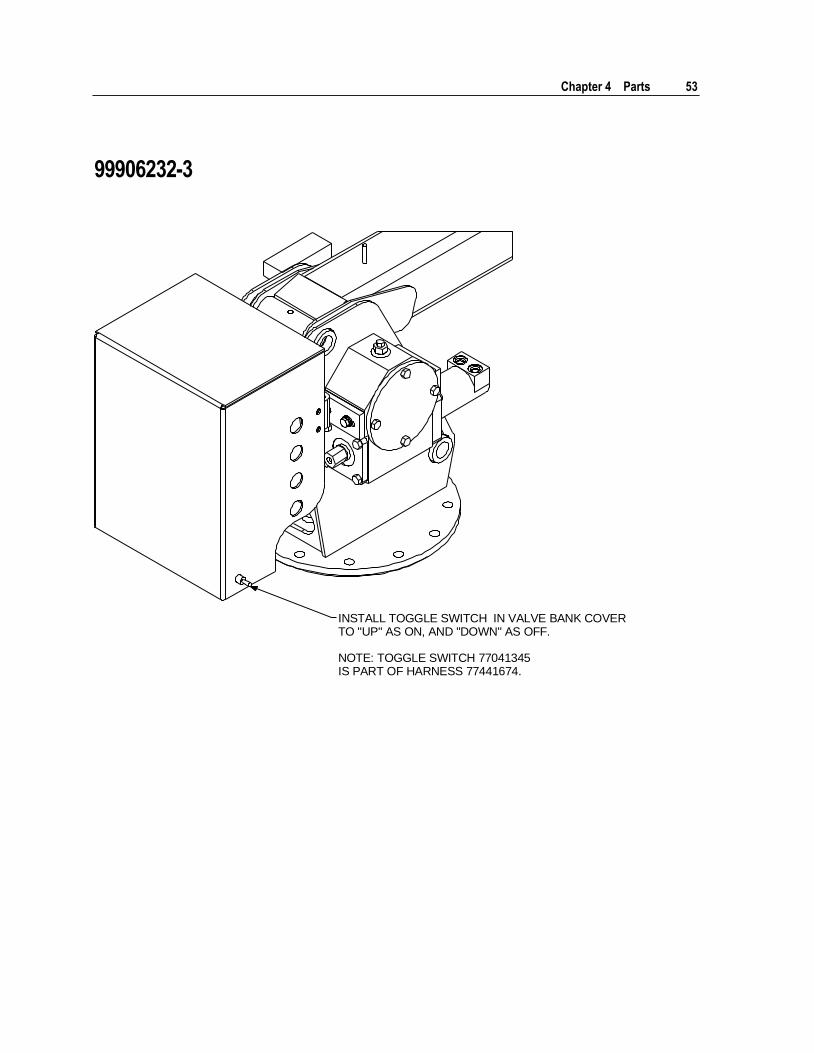
99906232-3
INSTALL TOGGLE SWITCH IN VALVE BANK COVERTO "UP" AS ON, AND "DOWN" AS OFF.
NOTE: TOGGLE SWITCH 77041345IS PART OF HARNESS 77441674.
54
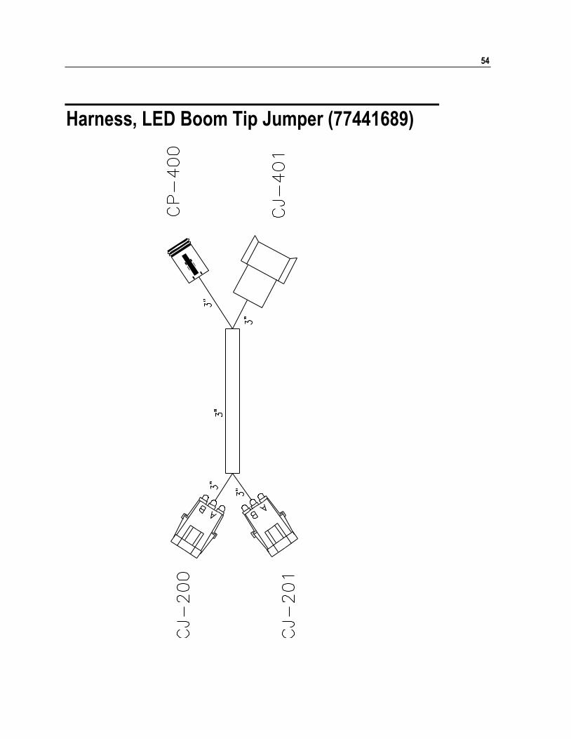
Harness, LED Boom Tip Jumper (77441689)
Chapter 4 Parts 55
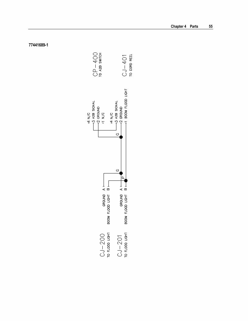
77441689-1
56
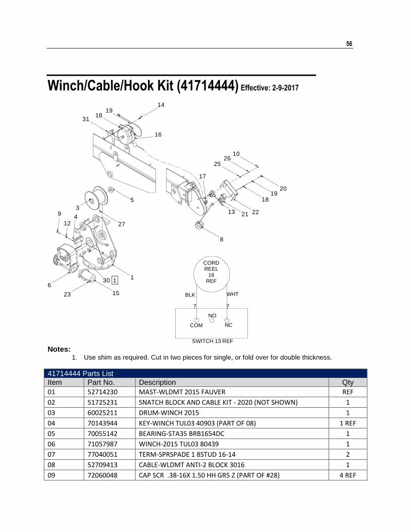
Winch/Cable/Hook Kit (41714444) Effective: 2-9-2017
7
WHT
NC
NO
COM
BLK
7
SWITCH 13 REF
CORDREEL
16REF
2019
18
222113
8
17
2526
10
16
1419
1831
5
27
1
15
30
23
6
93
412
1
Notes:
1. Use shim as required. Cut in two pieces for single, or fold over for double thickness.
41714444 Parts List
Item Part No. Description Qty
01 52714230 MAST-WLDMT 2015 FAUVER REF
02 51725231 SNATCH BLOCK AND CABLE KIT - 2020 (NOT SHOWN) 1
03 60025211 DRUM-WINCH 2015 1
04 70143944 KEY-WINCH TUL03 40903 (PART OF 08) 1 REF
05 70055142 BEARING-STA35 BRB1654DC 1
06 71057987 WINCH-2015 TUL03 80439 1
07 77040051 TERM-SPRSPADE 1 8STUD 16-14 2
08 52709413 CABLE-WLDMT ANTI-2 BLOCK 3016 1
09 72060048 CAP SCR .38-16X 1.50 HH GR5 Z (PART OF #28) 4 REF
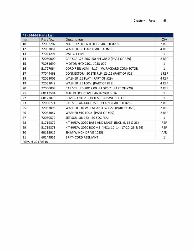
Chapter 4 Parts 57
41714444 Parts List
Item Part No. Description Qty
10 72062207 NUT 8-32 HEX NYLOCK (PART OF #29) 2 REF
12 72063051 WASHER .38 LOCK (PART OF #28) 4 REF
13 77041291 SWITCH-LIMIT 1
14 72060000 CAP SCR .25-20X .50 HH GR5 Z (PART OF #29) 2 REF
15 73051690 MOTOR-HYD C101-1033-009 1
16 51727064 CORD REEL ASM - 4.17' - W/PACKARD CONNECTOR 1
17 77044468 CONNECTOR- .50 STR RLF .12-.25 (PART OF #29) 1 REF
18 72063001 WASHER .25 FLAT (PART OF #29) 4 REF
19 72063049 WASHER .25 LOCK (PART OF #29) 4 REF
20 72060008 CAP SCR .25-20X 2.00 HH GR5 Z (PART OF #29) 2 REF
21 60113594 MTG BLOCK-COVER ANTI-2BLK 5016 1
22 60127876 COVER-ANTI 2 BLOCK MICRO SWITCH LEFT 1
23 72060774 CAP SCR .44-14X 1.25 SH PLAIN (PART OF #28) 2 REF
25 72063098 WASHER .16 W FLAT ANSI B27.2Z (PART OF #29) 2 REF
26 72063047 WASHER #10 LOCK (PART OF #29) 2 REF
27 72060579 SET SCR .38-16X .50 SOC PLAI 1
28 51719377 KIT-HRDW 2020 BASE AND MAST (INCL: 9, 12 & 23) REF
29 51719378 KIT-HRDW 2020 BOOMS (INCL: 10, 14, 17-20, 25 & 26) REF
30 60132917 SHIM-WINCH DRIVE (.035) A/R
31 60144951 BRKT- CORD REEL MNT 1 REV. H 20170310
58
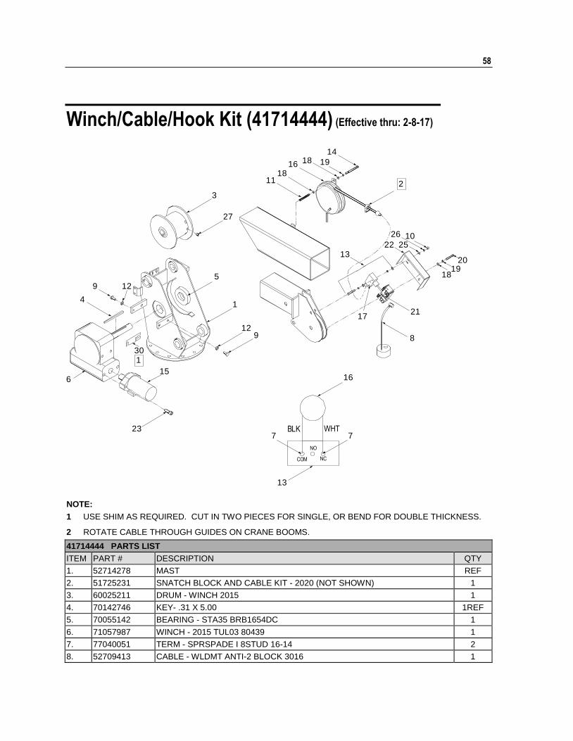
Winch/Cable/Hook Kit (41714444) (Effective thru: 2-8-17)
13
77
16
10
2019
18
26
25
14
1916
1118
18
22
8
17
13
21
5
1
9
30
15
12
23
6
4
12
3
27
9
1
2
WHTBLK
COM NC
NO
NOTE:
1 USE SHIM AS REQUIRED. CUT IN TWO PIECES FOR SINGLE, OR BEND FOR DOUBLE THICKNESS.
2 ROTATE CABLE THROUGH GUIDES ON CRANE BOOMS.
41714444 PARTS LIST
ITEM PART # DESCRIPTION QTY
1. 52714278 MAST REF
2. 51725231 SNATCH BLOCK AND CABLE KIT - 2020 (NOT SHOWN) 1
3. 60025211 DRUM - WINCH 2015 1
4. 70142746 KEY- .31 X 5.00 1REF
5. 70055142 BEARING - STA35 BRB1654DC 1
6. 71057987 WINCH - 2015 TUL03 80439 1
7. 77040051 TERM - SPRSPADE I 8STUD 16-14 2
8. 52709413 CABLE - WLDMT ANTI-2 BLOCK 3016 1
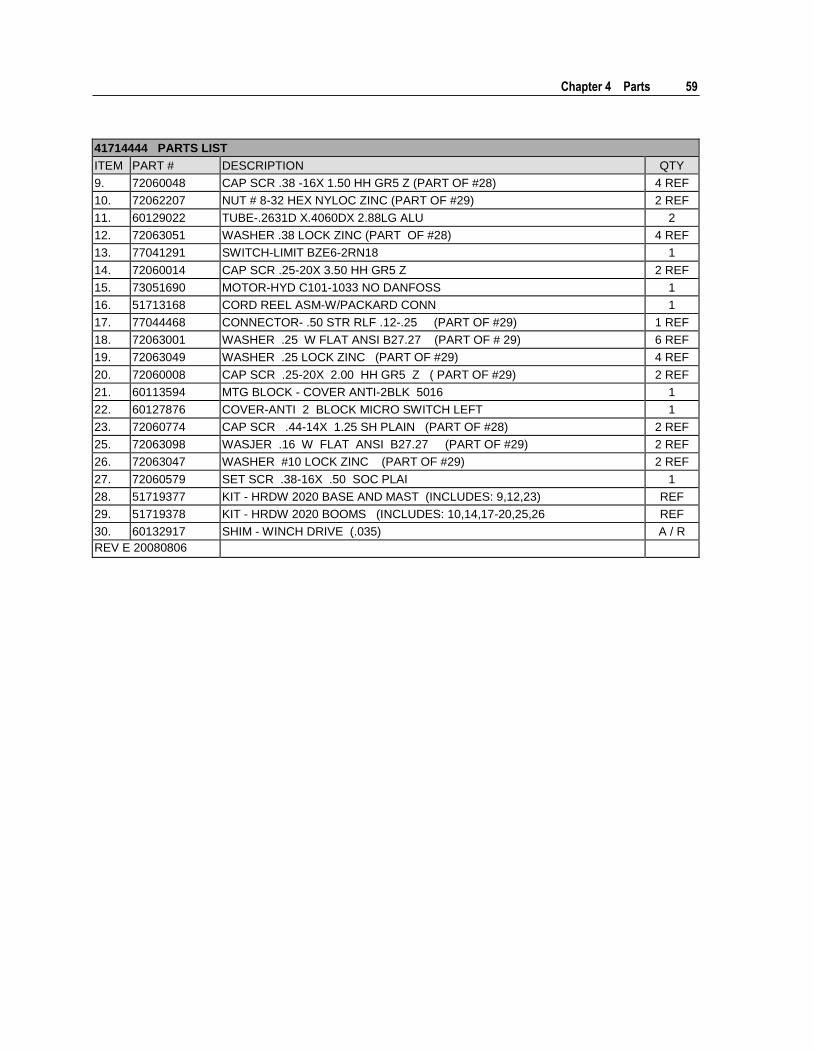
Chapter 4 Parts 59
41714444 PARTS LIST
ITEM PART # DESCRIPTION QTY
9. 72060048 CAP SCR .38 -16X 1.50 HH GR5 Z (PART OF #28) 4 REF
10. 72062207 NUT # 8-32 HEX NYLOC ZINC (PART OF #29) 2 REF
11. 60129022 TUBE-.2631D X.4060DX 2.88LG ALU 2
12. 72063051 WASHER .38 LOCK ZINC (PART OF #28) 4 REF
13. 77041291 SWITCH-LIMIT BZE6-2RN18 1
14. 72060014 CAP SCR .25-20X 3.50 HH GR5 Z 2 REF
15. 73051690 MOTOR-HYD C101-1033 NO DANFOSS 1
16. 51713168 CORD REEL ASM-W/PACKARD CONN 1
17. 77044468 CONNECTOR- .50 STR RLF .12-.25 (PART OF #29) 1 REF
18. 72063001 WASHER .25 W FLAT ANSI B27.27 (PART OF # 29) 6 REF
19. 72063049 WASHER .25 LOCK ZINC (PART OF #29) 4 REF
20. 72060008 CAP SCR .25-20X 2.00 HH GR5 Z ( PART OF #29) 2 REF
21. 60113594 MTG BLOCK - COVER ANTI-2BLK 5016 1
22. 60127876 COVER-ANTI 2 BLOCK MICRO SWITCH LEFT 1
23. 72060774 CAP SCR .44-14X 1.25 SH PLAIN (PART OF #28) 2 REF
25. 72063098 WASJER .16 W FLAT ANSI B27.27 (PART OF #29) 2 REF
26. 72063047 WASHER #10 LOCK ZINC (PART OF #29) 2 REF
27. 72060579 SET SCR .38-16X .50 SOC PLAI 1
28. 51719377 KIT - HRDW 2020 BASE AND MAST (INCLUDES: 9,12,23) REF
29. 51719378 KIT - HRDW 2020 BOOMS (INCLUDES: 10,14,17-20,25,26 REF
30. 60132917 SHIM - WINCH DRIVE (.035) A / R
REV E 20080806
60 2020 Parts & Specifications Manual Part # 99901222
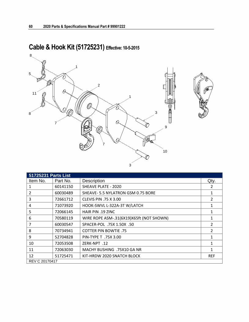
Cable & Hook Kit (51725231) Effective: 10-5-2015
3
1
2
1
8
5
11
8
7
7
3
10
9
51725231 Parts List
Item No. Part No. Description Qty.
1 60141150 SHEAVE PLATE - 2020 2
2 60030489 SHEAVE- 5.5 NYLATRON GSM 0.75 BORE 1
3 72661712 CLEVIS PIN .75 X 3.00 2
4 71073920 HOOK-SWVL L-322A-3T W/LATCH 1
5 72066145 HAIR PIN .19 ZINC 1
6 70580119 WIRE ROPE ASM-.31(6X19)X65ft (NOT SHOWN) 1
7 60030547 SPACER-POL .75X 1.50X .50 2
8 70734941 COTTER PIN BOWTIE .75 2
9 52704828 PIN-TYPE T .75X 3.00 1
10 72053508 ZERK-NPT .12 1
11 72063030 MACHY BUSHING .75X10 GA NR 1
12 51725471 KIT-HRDW 2020 SNATCH BLOCK REF REV C 20170417
Chapter 4 Parts 61
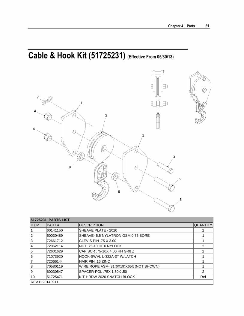
Cable & Hook Kit (51725231) (Effective From 05/30/13)
1
2
1
3
4
4
5
5
7
9
9
51725231 PARTS LIST
ITEM PART # DESCRIPTION QUANTITY
1 60141150 SHEAVE PLATE - 2020 2
2 60030489 SHEAVE- 5.5 NYLATRON GSM 0.75 BORE 1
3 72661712 CLEVIS PIN .75 X 3.00 1
4 72062114 NUT .75-10 HEX NYLOCK 2
5 72601629 CAP SCR .75-10X 4.00 HH GR8 Z 2
6 71073920 HOOK-SWVL L-322A-3T W/LATCH 1
7 72066144 HAIR PIN .16 ZINC 1
8 70580119 WIRE ROPE ASM-.31(6X19)X65ft (NOT SHOWN) 1
9 60030547 SPACER-POL .75X 1.50X .50 2
10 51725471 KIT-HRDW 2020 SNATCH BLOCK Ref
REV B 20140911
62 2020 Parts & Specifications Manual Part # 99901222
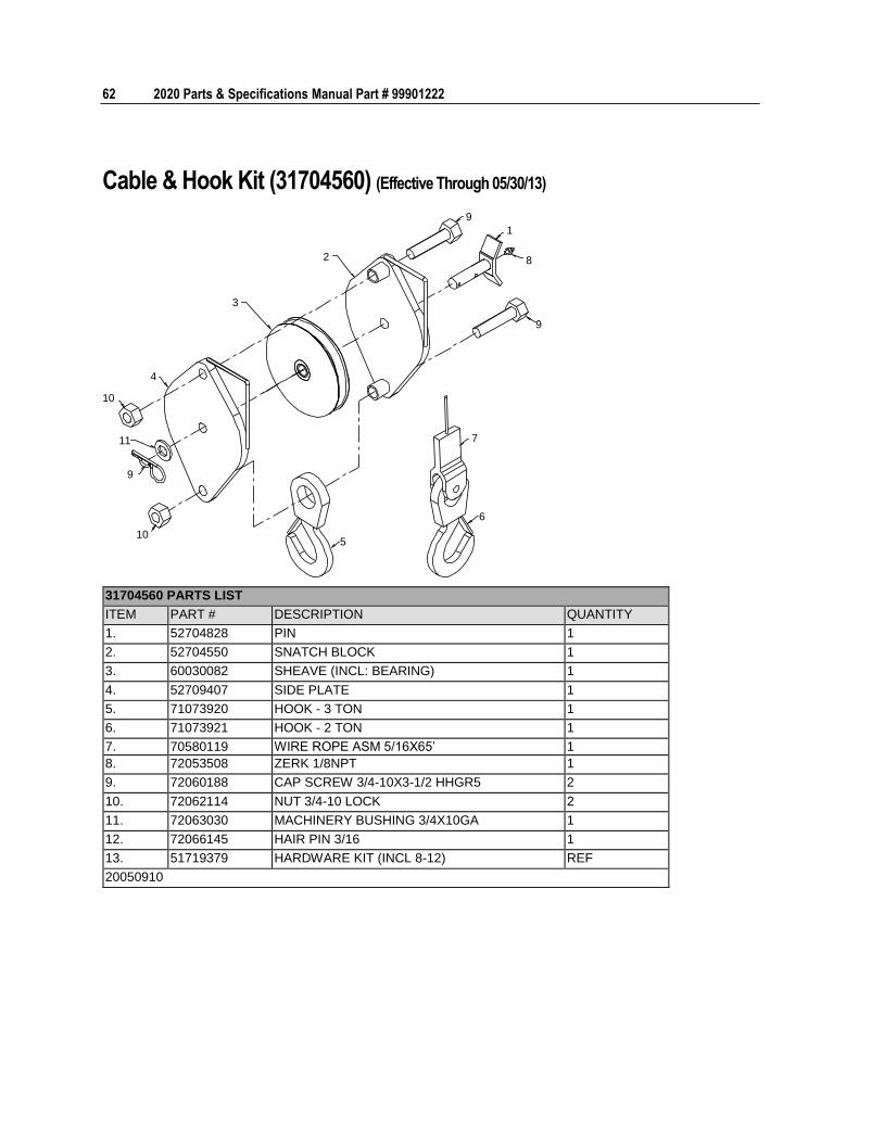
Cable & Hook Kit (31704560) (Effective Through 05/30/13)
10
11
9
10
4
3
2
5
7
6
9
1
8
9
31704560 PARTS LIST
ITEM PART # DESCRIPTION QUANTITY
1. 52704828 PIN 1
2. 52704550 SNATCH BLOCK 1
3. 60030082 SHEAVE (INCL: BEARING) 1
4. 52709407 SIDE PLATE 1
5. 71073920 HOOK - 3 TON 1
6. 71073921 HOOK - 2 TON 1
7. 70580119 WIRE ROPE ASM 5/16X65’ 1
8. 72053508 ZERK 1/8NPT 1
9. 72060188 CAP SCREW 3/4-10X3-1/2 HHGR5 2
10. 72062114 NUT 3/4-10 LOCK 2
11. 72063030 MACHINERY BUSHING 3/4X10GA 1
12. 72066145 HAIR PIN 3/16 1
13. 51719379 HARDWARE KIT (INCL 8-12) REF
20050910
Chapter 4 Parts 63
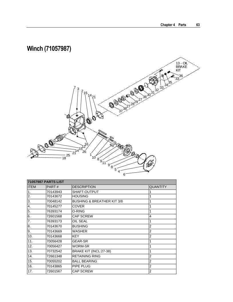
Winch (71057987)
2518
1612
1514
21 261
108
911
98
54
6
7 32
1514
21
13 - OILBRAKEKIT
3738
2728
2927
3830
3132
3334
3533
36
71057987 PARTS LIST
ITEM PART # DESCRIPTION QUANTITY
1. 70143943 SHAFT-OUTPUT 1
2. 70143672 HOUSING 1
3. 70048142 BUSHING & BREATHER KIT 3/8 1
4. 70145277 COVER 1
5. 76393174 O-RING 1
6. 72601568 CAP SCREW 4
7. 76393173 OIL SEAL 1
8. 70143670 BUSHING 2
9. 70143669 WASHER 2
10. 70143668 KEY 2
11. 70056428 GEAR-SR 1
12. 70056427 WORM-SR 1
13. 70732542 BRAKE KIT (INCL:27-38) 1
14. 72661348 RETAINING RING 2
15. 70055202 BALL BEARING 2
16. 70143865 PIPE PLUG 2
17. 72601567 CAP SCREW 2
64 2020 Parts & Specifications Manual Part # 99901222
71057987 PARTS LIST
ITEM PART # DESCRIPTION QUANTITY
21. 76393171 GASKET 2
25. — PROTECTOR (DISCARD) 1
26. 70143944 KEY 1
27. 70143664 *FRICTION DISC 2REF
28. 70143665 *BRAKE HUB 1REF
29. 70143662 *CAM CLUTCH 1REF
30. 70143661 *SPRING 1REF
31. 70143660 *THRUST WASHER 1REF
32. 70143666 *BRAKE HOUSING 1REF
33. 72601565 *CAP SCREW-SOC HD 2REF
34. 76393172 *WASHER-SEAL 1REF
35. 72601722 *LOCKNUT-SEAL 1REF
36. 72601723 *SET SCREW 1REF
37. 70143659 *BRAKE SPACER 1REF
38. 70143663 *STATOR PLATE 2REF
* PART OF ITEM 13
REV. B 20050916
Chapter 4 Parts 65
Controls & Hydraulics, Power Unit
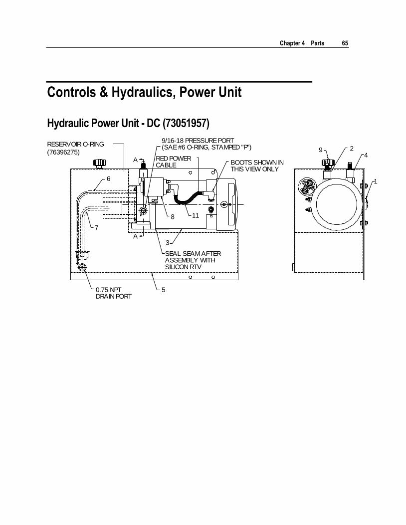
Hydraulic Power Unit - DC (73051957)
RESERVOIR O-RING
(76396275)
A
A
8 11
9/16-18 PRESSURE PORT(SAE #6 O-RING, STAMPED "P")
RED POWERCABLE BOOTS SHOWN IN
THIS VIEW ONLY
3
6
7
SEAL SEAM AFTERASSEMBLY WITHSILICON RTV
50.75 NPTDRAIN PORT
94
1
2
66 2020 Parts & Specifications Manual Part # 99901222
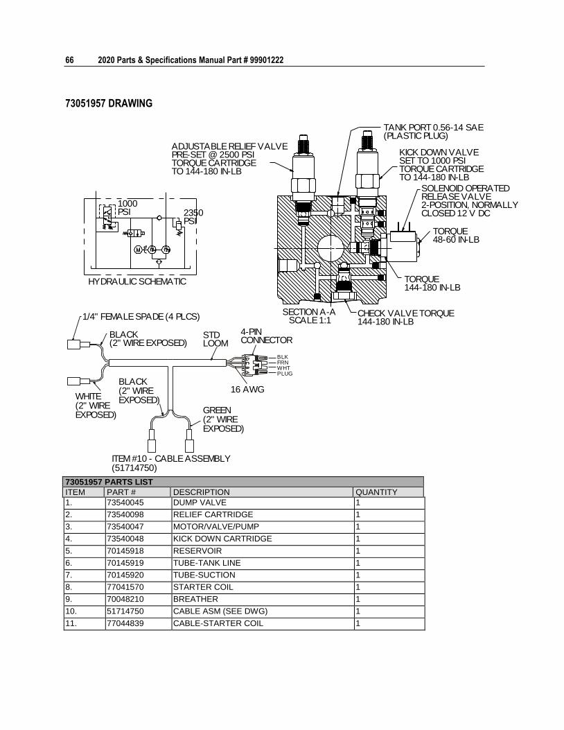
73051957 DRAWING
HYDRAULIC SCHEMATIC
1000PSI 2350
PSI
ADJUSTABLE RELIEF VALVEPRE-SET @ 2500 PSITORQUE CARTRIDGETO 144-180 IN-LB
TANK PORT 0.56-14 SAE(PLASTIC PLUG)
KICK DOWN VALVESET TO 1000 PSITORQUE CARTRIDGETO 144-180 IN-LB
SOLENOID OPERATEDRELEASE VALVE2-POSITION, NORMALLYCLOSED 12 V DC
TORQUE48-60 IN-LB
TORQUE144-180 IN-LB
CHECK VALVE TORQUE144-180 IN-LB
SECTION A-ASCALE 1:11/4" FEMALE SPADE (4 PLCS)
BLACK(2" WIRE EXPOSED)
STDLOOM
4-PINCONNECTOR
16 AWG
BLKFRNWHTPLUG
WHITE(2" WIREEXPOSED)
BLACK(2" WIREEXPOSED)
GREEN(2" WIREEXPOSED)
ITEM #10 - CABLE ASSEMBLY(51714750)
73051957 PARTS LIST
ITEM PART # DESCRIPTION QUANTITY
1. 73540045 DUMP VALVE 1
2. 73540098 RELIEF CARTRIDGE 1
3. 73540047 MOTOR/VALVE/PUMP 1
4. 73540048 KICK DOWN CARTRIDGE 1
5. 70145918 RESERVOIR 1
6. 70145919 TUBE-TANK LINE 1
7. 70145920 TUBE-SUCTION 1
8. 77041570 STARTER COIL 1
9. 70048210 BREATHER 1
10. 51714750 CABLE ASM (SEE DWG) 1
11. 77044839 CABLE-STARTER COIL 1
Chapter 4 Parts 67
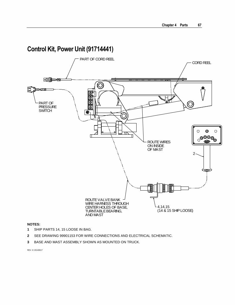
Control Kit, Power Unit (91714441)
PART OF CORD REELCORD REEL
ROUTE WIRESON INSIDEOF MAST
2
PART OFPRESSURESWITCH
ROUTE VALVE BANKWIRE HARNESS THROUGHCENTER HOLES OF BASE,TURNTABLE BEARING,AND MAST
4,14,15(14 & 15 SHIP LOOSE)
NOTES:
1 SHIP PARTS 14, 15 LOOSE IN BAG.
2 SEE DRAWING 99901153 FOR WIRE CONNECTIONS AND ELECTRICAL SCHEMATIC.
3 BASE AND MAST ASSEMBLY SHOWN AS MOUNTED ON TRUCK.
REV. E 20140617
68 2020 Parts & Specifications Manual Part # 99901222
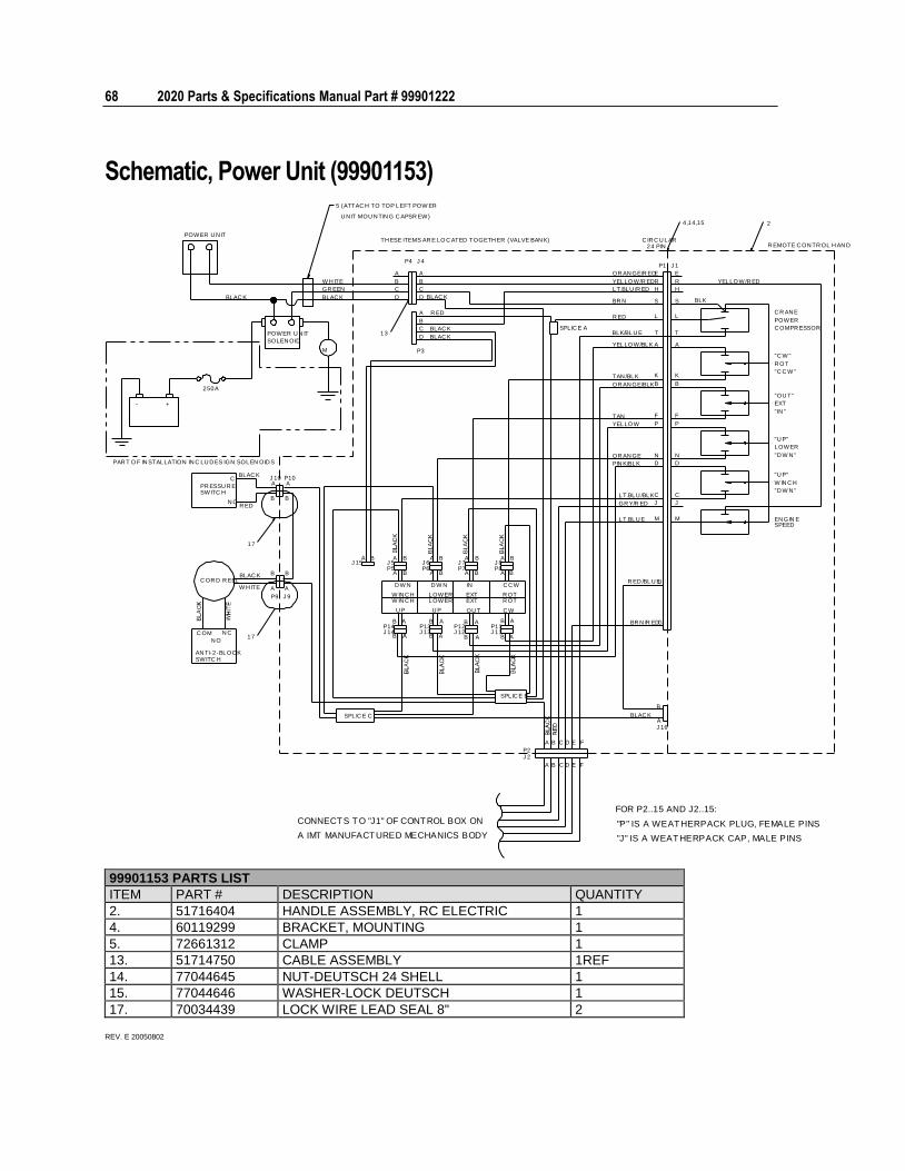
Schematic, Power Unit (99901153)
+-
M
13
17
17
4 ,14,15 2
5 (ATTAC H TO TOP LEFT POW ER
U N IT MOU N TIN G C APSR EW)
TH ESE ITEMS AR E LO C ATED TOGETH ER (VALVE BAN K)
C OR D R EEL
PR ESSU R E
N C
AN TI-2 -BLOC K
FOR P2..15 AND J2..15:
"P" IS A WEATHERPACK PLUG, FEMALE PINS
"J" IS A WEATHERPACK CAP, MALE PINS
N O
SWITC H
C OM
SWITC H
SPLIC E C
B B
A
B
P9
BLAC K
W H ITE
R EDN C
A
J 9
B
AJ 10
BLAC KC P10
A
J 15
W IN C HW IN C H
J 14P14
U P
D W N
B
B
A
B
J 5P5
B BA
C
D
A
B
P4
R EMOTE C ON TR OL H AN D LE
C OMPR ESSOR
SPLIC E B
P2
CA B FD E
B
A
A
B
LOWERLOWER
A
B
A
B
A
U P
D W N
BJ 13P13
J 12P12
BAJ 6P6
J 7P7
A
B
A
IN
EXT
OU T
EXT
B A
A
R OT
C W
R OT
B
C C W
B AJ 11P11
B A B
P8J 8
AJ 16
BLAC K
B
G
UR ED /BLU E
BR N /R ED
GR Y/R ED
LT.BLU E
J
M
J
M
PIN K/BLK
LT.BLU /BLK
OR AN GE N
D
C
OR AN GE/BLK
TAN /BLK
TAN
YELLO W
B
K
F
P
D
N
C
B
K
F
P
SPEEDEN GIN E
LOWER
"D W N "
"U P"
"D W N "
W IN C H
"U P"
"C C W "
R OT
"IN "
EXT
"OU T"
BLAC K
BLAC K
R ED
BLAC K
C
A
D
P3
C
D
B
J 4
A
B
SPLIC E A
24 PIN
P1
C IR C U LAR
LT.BLU /R ED
YELLO W/BLK
BLK/BLU E
BR N
R ED
H
S
A
T
L
OR AN GE/R ED
YELLO W/R ED
E
R
H
S
A
T
L
J 1
E
R
C R AN E
"C W "
POWER
POWER U N IT
POWER U N IT
SOLEN OID
W H ITE
GR EEN
BLAC K
PAR T O F IN STALLATION IN C LU D ES IGN SOLEN OID S
CONNECT S T O "J1" OF CONTROL BOX ON
A IMT MANUFACT URED MECHANICS BODY
C
J 2
A B D E F
YELLO W/R ED
BLKBLAC K
250A
99901153 PARTS LIST
ITEM PART # DESCRIPTION QUANTITY
2. 51716404 HANDLE ASSEMBLY, RC ELECTRIC 1
4. 60119299 BRACKET, MOUNTING 1
5. 72661312 CLAMP 1
13. 51714750 CABLE ASSEMBLY 1REF
14. 77044645 NUT-DEUTSCH 24 SHELL 1
15. 77044646 WASHER-LOCK DEUTSCH 1
17. 70034439 LOCK WIRE LEAD SEAL 8" 2
REV. E 20050802
Chapter 4 Parts 69
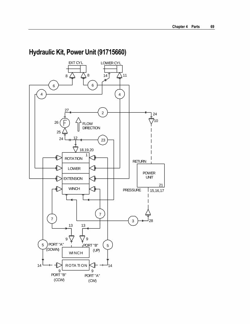
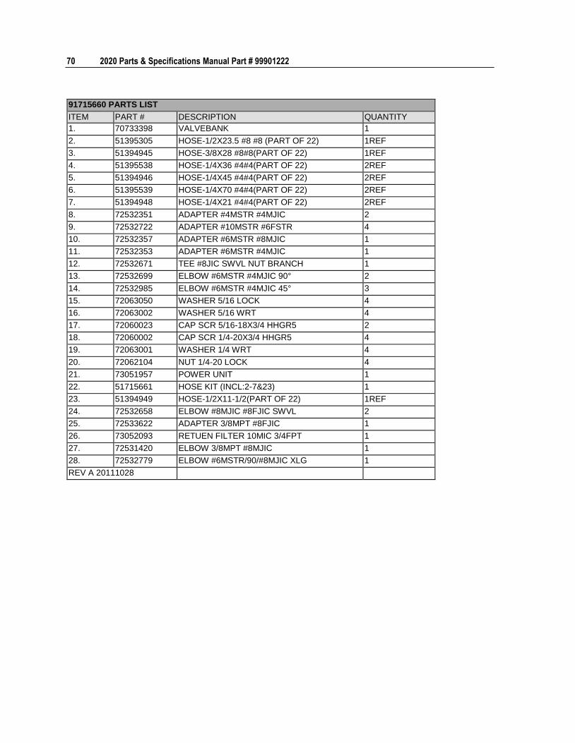
Hydraulic Kit, Power Unit (91715660)
EXT CYL LOWER CYL
8 8
6 6
4 4
14 11
27
26
25
24 12
FLOWDIRECTION
2 24
10
23
RETURN
PRESSURE
POWERUNIT
21
15,16,17
ROTATION
LOWER
EXTENSION
WINCH
1
7
7
3 28
9 9
5 5PORT "A"
(DOWN) PORT "B"
(UP)WI NCH
ROTA TI ON14 14
9 9PORT "B"
(CCW) PORT "A"
(CW)
18,19,20
13 13
70 2020 Parts & Specifications Manual Part # 99901222
91715660 PARTS LIST
ITEM PART # DESCRIPTION QUANTITY
1. 70733398 VALVEBANK 1
2. 51395305 HOSE-1/2X23.5 #8 #8 (PART OF 22) 1REF
3. 51394945 HOSE-3/8X28 #8#8(PART OF 22) 1REF
4. 51395538 HOSE-1/4X36 #4#4(PART OF 22) 2REF
5. 51394946 HOSE-1/4X45 #4#4(PART OF 22) 2REF
6. 51395539 HOSE-1/4X70 #4#4(PART OF 22) 2REF
7. 51394948 HOSE-1/4X21 #4#4(PART OF 22) 2REF
8. 72532351 ADAPTER #4MSTR #4MJIC 2
9. 72532722 ADAPTER #10MSTR #6FSTR 4
10. 72532357 ADAPTER #6MSTR #8MJIC 1
11. 72532353 ADAPTER #6MSTR #4MJIC 1
12. 72532671 TEE #8JIC SWVL NUT BRANCH 1
13. 72532699 ELBOW #6MSTR #4MJIC 90° 2
14. 72532985 ELBOW #6MSTR #4MJIC 45° 3
15. 72063050 WASHER 5/16 LOCK 4
16. 72063002 WASHER 5/16 WRT 4
17. 72060023 CAP SCR 5/16-18X3/4 HHGR5 2
18. 72060002 CAP SCR 1/4-20X3/4 HHGR5 4
19. 72063001 WASHER 1/4 WRT 4
20. 72062104 NUT 1/4-20 LOCK 4
21. 73051957 POWER UNIT 1
22. 51715661 HOSE KIT (INCL:2-7&23) 1
23. 51394949 HOSE-1/2X11-1/2(PART OF 22) 1REF
24. 72532658 ELBOW #8MJIC #8FJIC SWVL 2
25. 72533622 ADAPTER 3/8MPT #8FJIC 1
26. 73052093 RETUEN FILTER 10MIC 3/4FPT 1
27. 72531420 ELBOW 3/8MPT #8MJIC 1
28. 72532779 ELBOW #6MSTR/90/#8MJIC XLG 1
REV A 20111028
Chapter 4 Parts 71
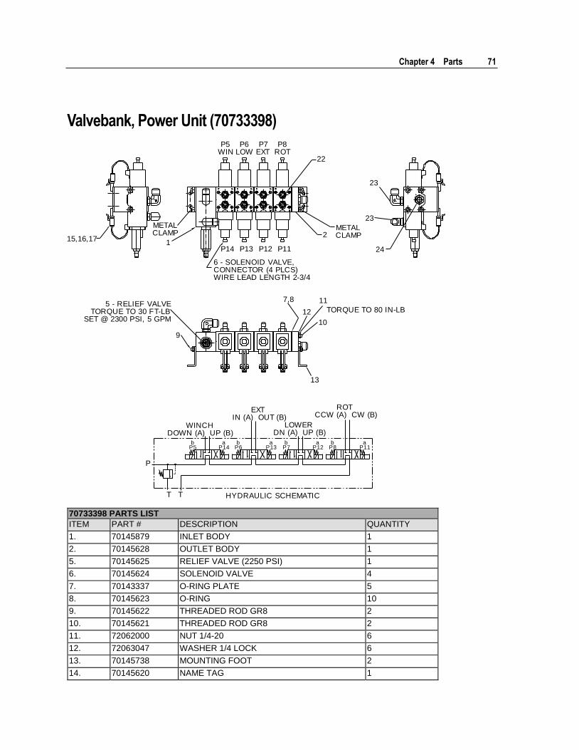
Valvebank, Power Unit (70733398)
P5WIN
P8ROT
P6LOW
P7EXT
P14 P11P13 P12
2METALCLAMP
22
23
23
24
15,16,171
METALCLAMP
6 - SOLENOID VALVE,CONNECTOR (4 PLCS)WIRE LEAD LENGTH 2-3/4
7,8
12
11
TORQUE TO 80 IN-LB
10
13
9
5 - RELIEF VALVETORQUE TO 30 FT-LB
SET @ 2300 PSI, 5 GPM
HYDRAULIC SCHEMATICT T
P
WINCHDOWN (A) UP (B)
EXTIN (A) OUT (B)
ROTCCW (A) CW (B)
LOWERDN (A) UP (B)
bP5
aP14
bP6
aP13
bP7
aP12
bP8
aP11
70733398 PARTS LIST
ITEM PART # DESCRIPTION QUANTITY
1. 70145879 INLET BODY 1
2. 70145628 OUTLET BODY 1
5. 70145625 RELIEF VALVE (2250 PSI) 1
6. 70145624 SOLENOID VALVE 4
7. 70143337 O-RING PLATE 5
8. 70145623 O-RING 10
9. 70145622 THREADED ROD GR8 2
10. 70145621 THREADED ROD GR8 2
11. 72062000 NUT 1/4-20 6
12. 72063047 WASHER 1/4 LOCK 6
13. 70145738 MOUNTING FOOT 2
14. 70145620 NAME TAG 1
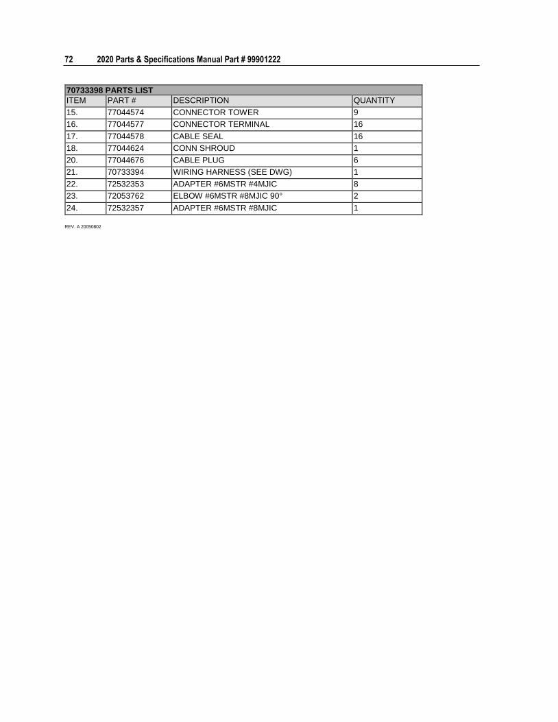
72 2020 Parts & Specifications Manual Part # 99901222
70733398 PARTS LIST
ITEM PART # DESCRIPTION QUANTITY
15. 77044574 CONNECTOR TOWER 9
16. 77044577 CONNECTOR TERMINAL 16
17. 77044578 CABLE SEAL 16
18. 77044624 CONN SHROUD 1
20. 77044676 CABLE PLUG 6
21. 70733394 WIRING HARNESS (SEE DWG) 1
22. 72532353 ADAPTER #6MSTR #4MJIC 8
23. 72053762 ELBOW #6MSTR #8MJIC 90° 2
24. 72532357 ADAPTER #6MSTR #8MJIC 1
REV. A 20050802
Chapter 4 Parts 73
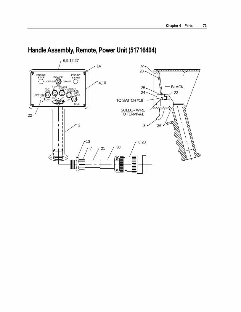
Handle Assembly, Remote, Power Unit (51716404)
2
13
7 21 30
8,20
3 26
23
BLACK
TO SWITCH #19
SOLDER WIRETO TERMINAL22
4,10
25
24
282914
6,9,12,27
ENGINESTOP POWER
OFF
CPRSR CRANE
ENGINESTART
OPTION
ROTCCW
CW
EXTIN
OUT
WINCHDOWN
UP
LOWERDOWN
UP
ENGSPDFAST
IDLE
74 2020 Parts & Specifications Manual Part # 99901222
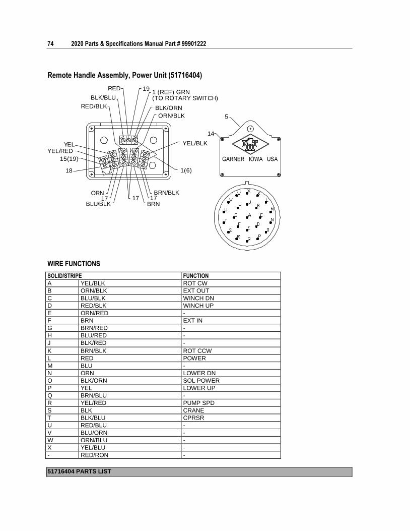
Remote Handle Assembly, Power Unit (51716404)
5
14
191 (REF) GRN(TO ROTARY SWITCH)
BLK/ORN
ORN/BLK
YEL/BLK
1(6)
ORN17
BLU/BLK17
BRN/BLK17
BRN
RED
BLK/BLU
RED/BLK
YEL/REDYEL
18
15(19)
WIRE FUNCTIONS
SOLID/STRIPE FUNCTION
A YEL/BLK ROT CW
B ORN/BLK EXT OUT
C BLU/BLK WINCH DN
D RED/BLK WINCH UP
E ORN/RED -
F BRN EXT IN
G BRN/RED -
H BLU/RED -
J BLK/RED -
K BRN/BLK ROT CCW
L RED POWER
M BLU -
N ORN LOWER DN
O BLK/ORN SOL POWER
P YEL LOWER UP
Q BRN/BLU -
R YEL/RED PUMP SPD
S BLK CRANE
T BLK/BLU CPRSR
U RED/BLU -
V BLU/ORN -
W ORN/BLU -
X YEL/BLU -
- RED/RON -
51716404 PARTS LIST
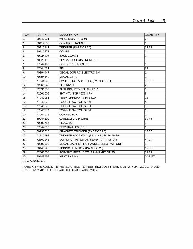
Chapter 4 Parts 75
ITEM PART # DESCRIPTION QUANTITY
1. 60045031 WIRE 18GA X 4 GRN 6
2. 60119335 CONTROL HANDLE 1
3. 60111141 TRIGGER (PART OF 25) 1REF
4. 60119277 COVER 1
5. 70034306 BACK COVER 1
6. 70029119 PLACARD, SERIAL NUMBER 1
7. 77044196 CORD GRIP, LOCTITE 1
8. 77044621 PIN 23
9. 70394447 DECAL-DGR RC ELECTRO SM 1
10. 70394142 DECAL-CTRL 1
11. 77044969 SWITCH, ROTARY ELEC (PART OF 25) 1REF
12. 72066340 POP RIVET 2
13. 72531833 BUSHING, RED STL 3/4 X 1/2 1
14. 72061009 SHT MTL SCR #6X3/4 PH 8
15. 77040051 TERM-SPRSPD #8 16-14GA 19
17. 77040372 TOGGLE SWITCH SPDT 4
18. 77040373 TOGGLE SWITCH SPST 1
19. 77040374 TOGGLE SWITCH SPDT 1
20. 77044579 CONNECTOR 1
21. 89044100 CABLE 18GA 24WIRE 30 FT
22. 70392785 PLUG, 1/2 1
23. 77044695 TERMINAL, FSLPON 1
24. 70733518 BRACKET, TRIGGER (PART OF 25) 1REF
25. 51716499 TRIGGER ASSEMBLY (INCL 3,11,24,26,28-29) 1
26. 72601346 SCR-MACH #8-32 PAN HEAD (PART OF 25) 4REF
27. 70395995 DECAL-CAUTION RC HANDLE ELEC PWR UNIT 1
28. 70143223 SPRING, TENSION (PART OF 25) 1REF
29. 72061000 SCR-SHT METAL #6X1/2 PH (PART OF 25) 1REF
30. 70145495 HEAT SHRINK 0.33 FT
REV. A 20050602
NOTE: KIT # 51717816, TETHERED CABLE - 30 FEET, INCLUDES ITEMS 8, 15 (QTY 24), 20, 21, AND 30. ORDER 51717816 TO REPLACE THE CABLE ASSEMBLY.
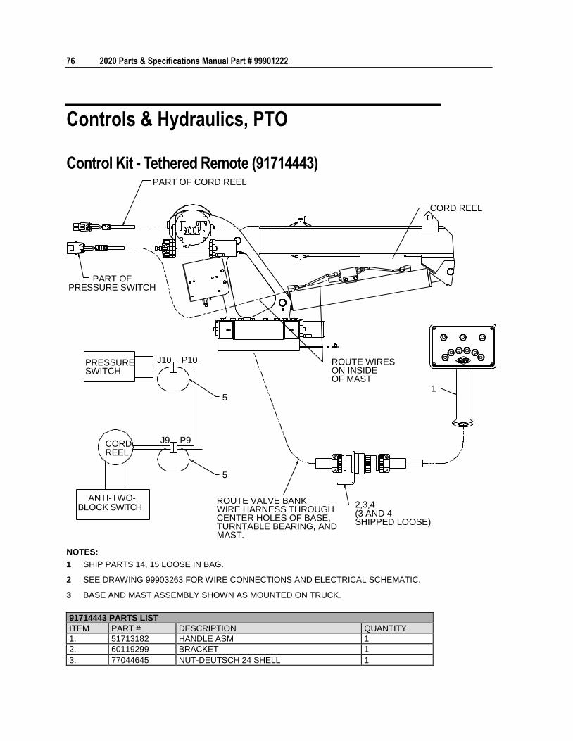
76 2020 Parts & Specifications Manual Part # 99901222
Controls & Hydraulics, PTO
Control Kit - Tethered Remote (91714443) PART OF CORD REEL
PART OFPRESSURE SWITCH
CORD REEL
ROUTE WIRESON INSIDEOF MAST
1
ROUTE VALVE BANKWIRE HARNESS THROUGHCENTER HOLES OF BASE,TURNTABLE BEARING, ANDMAST.
2,3,4(3 AND 4SHIPPED LOOSE)
PRESSURESWITCH
ANTI-TWO-
CORDREEL
J10 P10
J9 P9
5
5
BLOCK SWITCH
NOTES:
1 SHIP PARTS 14, 15 LOOSE IN BAG.
2 SEE DRAWING 99903263 FOR WIRE CONNECTIONS AND ELECTRICAL SCHEMATIC.
3 BASE AND MAST ASSEMBLY SHOWN AS MOUNTED ON TRUCK.
91714443 PARTS LIST
ITEM PART # DESCRIPTION QUANTITY
1. 51713182 HANDLE ASM 1
2. 60119299 BRACKET 1
3. 77044645 NUT-DEUTSCH 24 SHELL 1
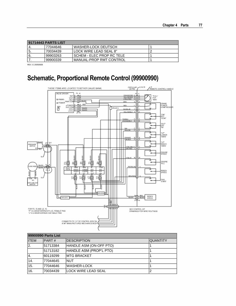
Chapter 4 Parts 77
91714443 PARTS LIST
4. 77044646 WASHER-LOCK DEUTSCH 1
5. 70034439 LOCK WIRE LEAD SEAL 8" 2
6. 99903263 SCHEM - ELEC PROP RC TELE 1
7. 99900339 MANUAL-PROP RMT CONTROL 1
REV. E 20050608
Schematic, Proportional Remote Control (99900990)
99900990 Parts List
ITEM PART # DESCRIPTION QUANTITY
2. 51713384 HANDLE ASM (ON-OFF PTO) 1
51713182 HANDLE ASM (PROP’L PTO) 1
4. 60119299 MTG BRACKET 1
14. 77044645 NUT 1
15. 77044646 WASHER-LOCK 1
16. 70034439 LOCK WIRE LEAD SEAL 2
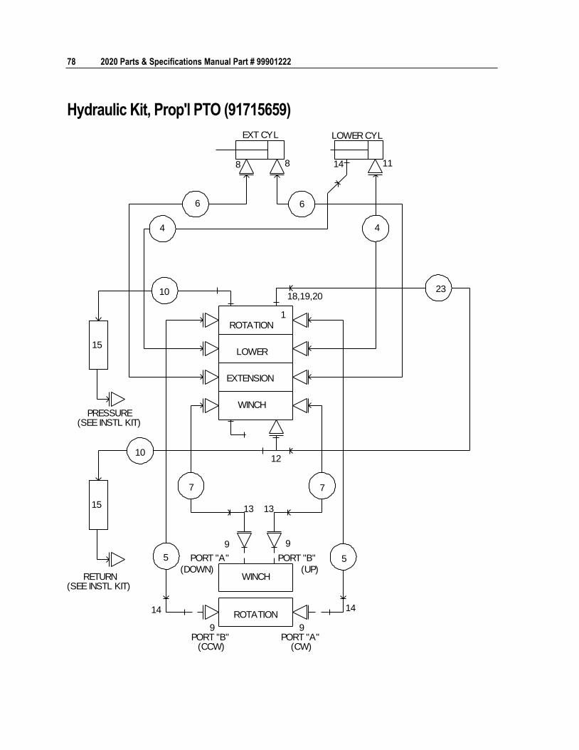
78 2020 Parts & Specifications Manual Part # 99901222
Hydraulic Kit, Prop'l PTO (91715659)
EXT CYL LOWER CYL
8 8
6 6
4 4
14 11
10 23
15
PRESSURE(SEE INSTL KIT)
RETURN(SEE INSTL KIT)
10
15
12
18,19,20
ROTATION
LOWER
EXTENSION
WINCH
1
7 7
13 13
9 9
5 5 PORT "A"
(DOWN)
PORT "B"
(UP)WINCH
ROTATION14 14
9PORT "B"
(CCW)
9PORT "A"
(CW)
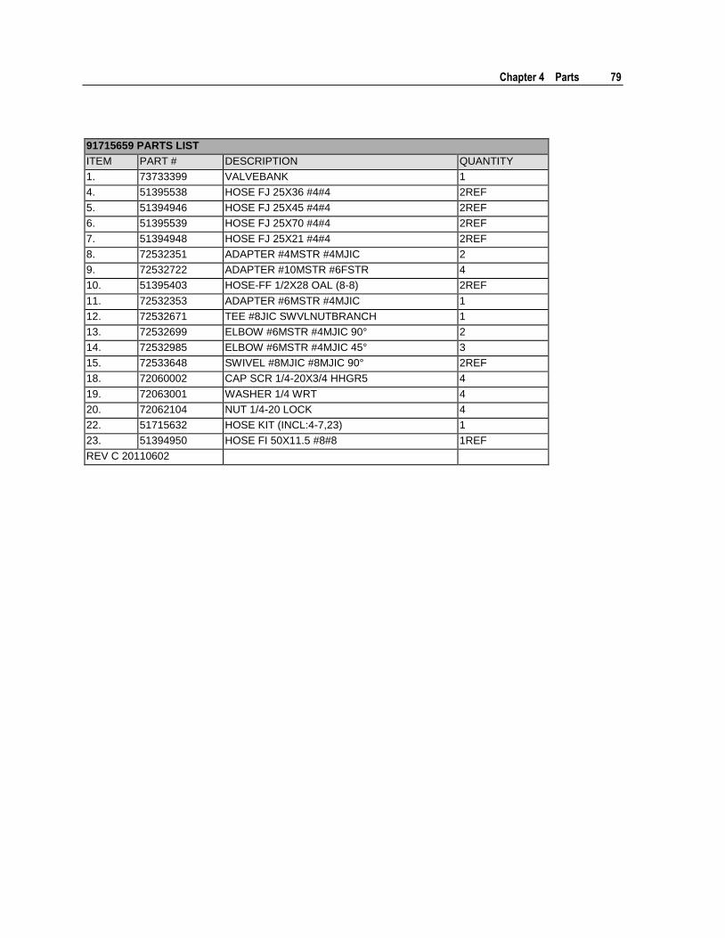
Chapter 4 Parts 79
91715659 PARTS LIST
ITEM PART # DESCRIPTION QUANTITY
1. 73733399 VALVEBANK 1
4. 51395538 HOSE FJ 25X36 #4#4 2REF
5. 51394946 HOSE FJ 25X45 #4#4 2REF
6. 51395539 HOSE FJ 25X70 #4#4 2REF
7. 51394948 HOSE FJ 25X21 #4#4 2REF
8. 72532351 ADAPTER #4MSTR #4MJIC 2
9. 72532722 ADAPTER #10MSTR #6FSTR 4
10. 51395403 HOSE-FF 1/2X28 OAL (8-8) 2REF
11. 72532353 ADAPTER #6MSTR #4MJIC 1
12. 72532671 TEE #8JIC SWVLNUTBRANCH 1
13. 72532699 ELBOW #6MSTR #4MJIC 90° 2
14. 72532985 ELBOW #6MSTR #4MJIC 45° 3
15. 72533648 SWIVEL #8MJIC #8MJIC 90° 2REF
18. 72060002 CAP SCR 1/4-20X3/4 HHGR5 4
19. 72063001 WASHER 1/4 WRT 4
20. 72062104 NUT 1/4-20 LOCK 4
22. 51715632 HOSE KIT (INCL:4-7,23) 1
23. 51394950 HOSE FI 50X11.5 #8#8 1REF
REV C 20110602
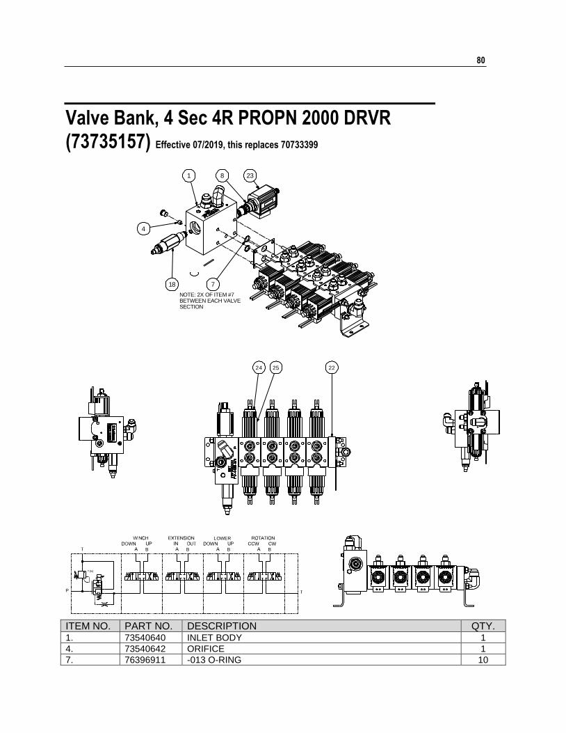
80
Valve Bank, 4 Sec 4R PROPN 2000 DRVR (73735157) Effective 07/2019, this replaces 70733399
? (Is)
B B B B
LOWER
P
18
8 23
4
1
7
222524
NOTE: 2X OF ITEM #7BETWEEN EACH VALVESECTION
ITEM NO. PART NO. DESCRIPTION QTY. 1. 73540640 INLET BODY 1
4. 73540642 ORIFICE 1
7. 76396911 -013 O-RING 10
Chapter 4 Parts 81
ITEM NO. PART NO. DESCRIPTION QTY. 8. 73540645 PROPORTIONAL INLET VALVE 1
18. 73540647 RELIEF VALVE 1
22. 70145628 OUTLET BODY 1
23. 73540646 COIL-12VDC LEADWIRE 1
24. 73540641 VALVE SECTION 4
25. 73540643 COIL-12VDC 8
26. 70733394 WIRE HARNESS 1
27. 77040784 VALVE DRIVER 1
REV. INITIAL RELEASE
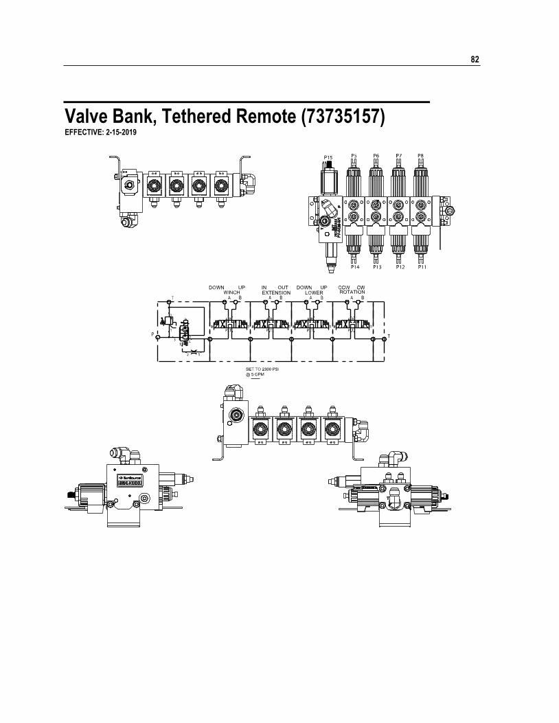
82
Valve Bank, Tethered Remote (73735157) EFFECTIVE: 2-15-2019
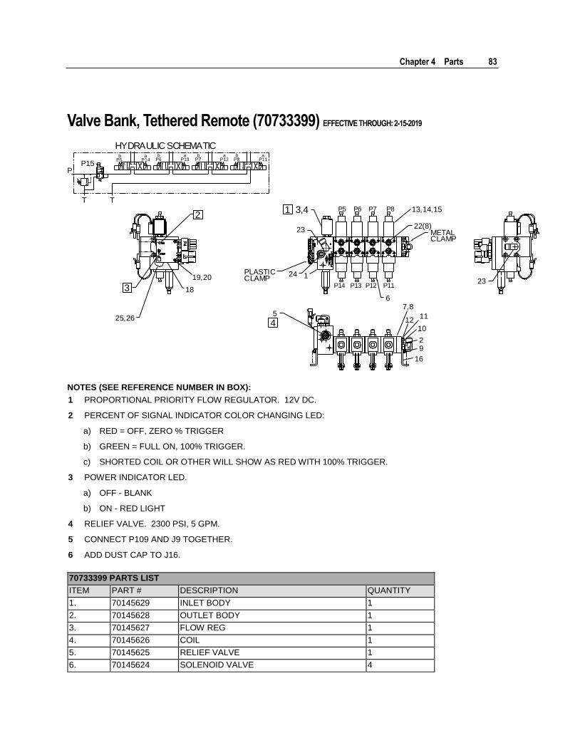
Chapter 4 Parts 83
Valve Bank, Tethered Remote (70733399) EFFECTIVE THROUGH: 2-15-2019
6
P14 P13 P12 P11
METALCLAMP
23
22(8)
13,14,15P5 P6 P7 P8
PLASTICCLAMP
24 1
23
57,8
1112
10
29
16
25,26
18
19,20
P
T T
P15b
P5a
P14b
P6a
P13b
P7a
P12b
P8a
P11
3,412
3
4
HYDRAULIC SCHEMATIC
NOTES (SEE REFERENCE NUMBER IN BOX):
1 PROPORTIONAL PRIORITY FLOW REGULATOR. 12V DC.
2 PERCENT OF SIGNAL INDICATOR COLOR CHANGING LED:
a) RED = OFF, ZERO % TRIGGER
b) GREEN = FULL ON, 100% TRIGGER.
c) SHORTED COIL OR OTHER WILL SHOW AS RED WITH 100% TRIGGER.
3 POWER INDICATOR LED.
a) OFF - BLANK
b) ON - RED LIGHT
4 RELIEF VALVE. 2300 PSI, 5 GPM.
5 CONNECT P109 AND J9 TOGETHER.
6 ADD DUST CAP TO J16.
70733399 PARTS LIST
ITEM PART # DESCRIPTION QUANTITY
1. 70145629 INLET BODY 1
2. 70145628 OUTLET BODY 1
3. 70145627 FLOW REG 1
4. 70145626 COIL 1
5. 70145625 RELIEF VALVE 1
6. 70145624 SOLENOID VALVE 4
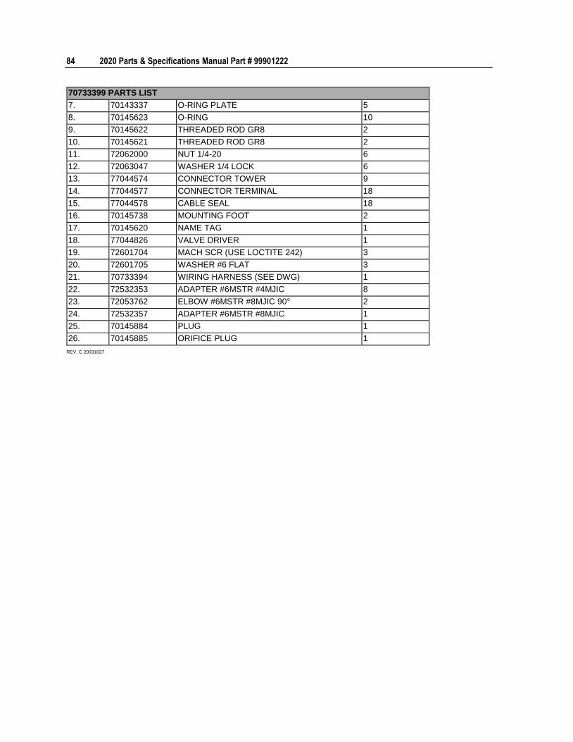
84 2020 Parts & Specifications Manual Part # 99901222
70733399 PARTS LIST
7. 70143337 O-RING PLATE 5
8. 70145623 O-RING 10
9. 70145622 THREADED ROD GR8 2
10. 70145621 THREADED ROD GR8 2
11. 72062000 NUT 1/4-20 6
12. 72063047 WASHER 1/4 LOCK 6
13. 77044574 CONNECTOR TOWER 9
14. 77044577 CONNECTOR TERMINAL 18
15. 77044578 CABLE SEAL 18
16. 70145738 MOUNTING FOOT 2
17. 70145620 NAME TAG 1
18. 77044826 VALVE DRIVER 1
19. 72601704 MACH SCR (USE LOCTITE 242) 3
20. 72601705 WASHER #6 FLAT 3
21. 70733394 WIRING HARNESS (SEE DWG) 1
22. 72532353 ADAPTER #6MSTR #4MJIC 8
23. 72053762 ELBOW #6MSTR #8MJIC 90° 2
24. 72532357 ADAPTER #6MSTR #8MJIC 1
25. 70145884 PLUG 1
26. 70145885 ORIFICE PLUG 1
REV. C 20031027
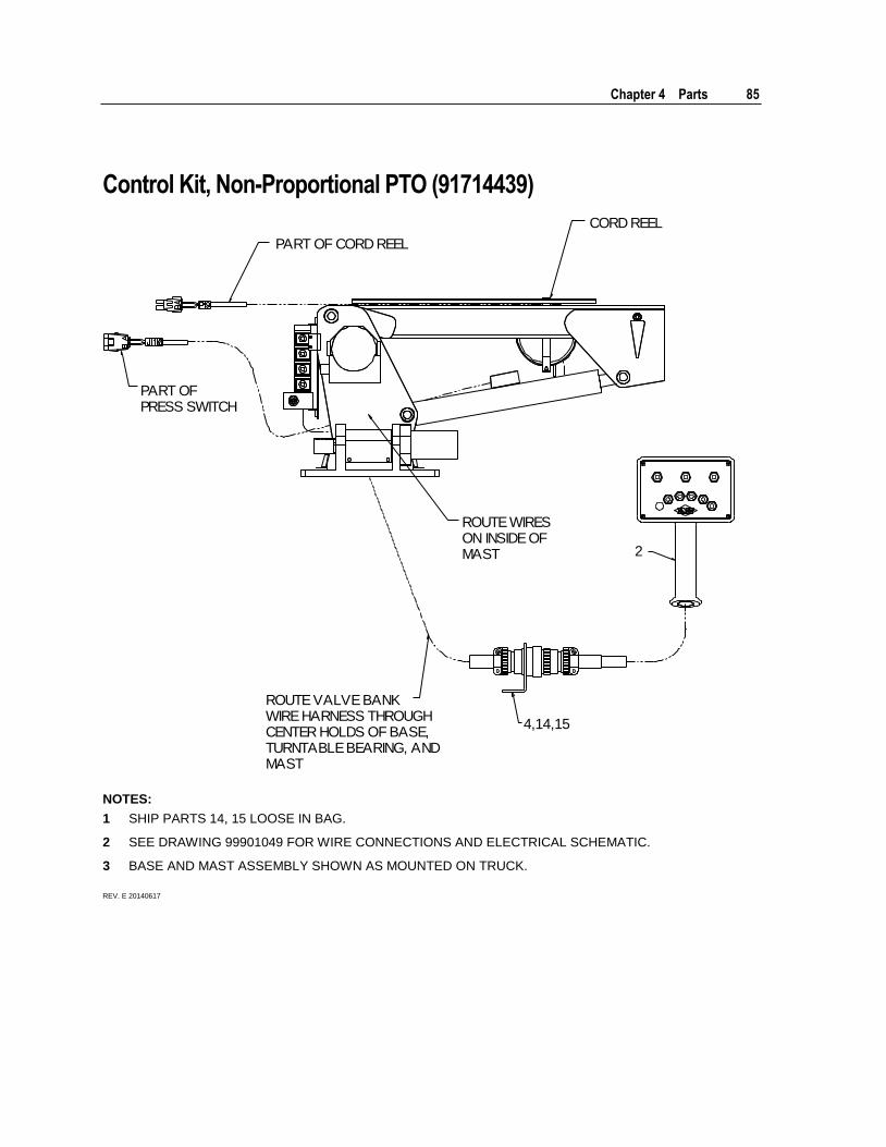
Chapter 4 Parts 85
Control Kit, Non-Proportional PTO (91714439)
CORD REEL
PART OF CORD REEL
PART OFPRESS SWITCH
ROUTE WIRESON INSIDE OFMAST
ROUTE VALVE BANKWIRE HARNESS THROUGHCENTER HOLDS OF BASE,TURNTABLE BEARING, ANDMAST
4,14,15
2
NOTES:
1 SHIP PARTS 14, 15 LOOSE IN BAG.
2 SEE DRAWING 99901049 FOR WIRE CONNECTIONS AND ELECTRICAL SCHEMATIC.
3 BASE AND MAST ASSEMBLY SHOWN AS MOUNTED ON TRUCK.
REV. E 20140617
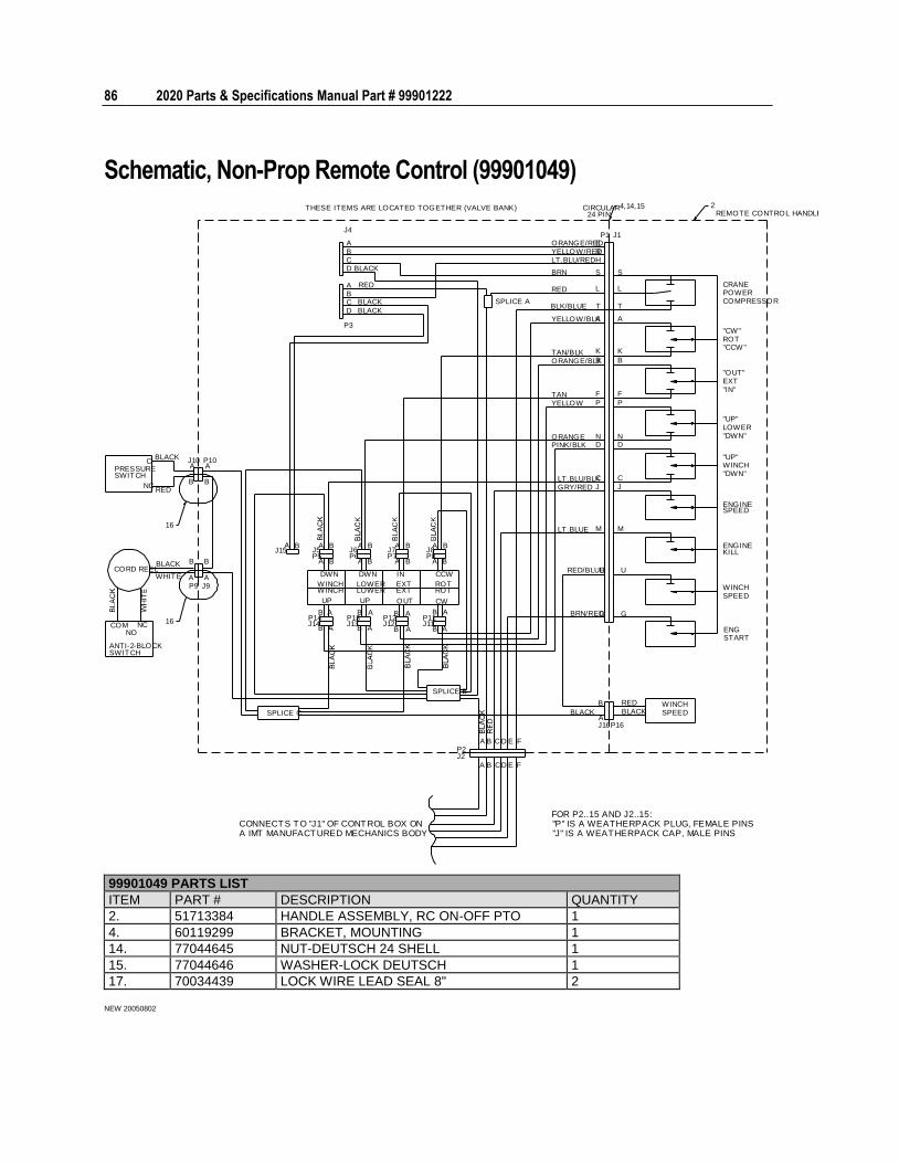
86 2020 Parts & Specifications Manual Part # 99901222
Schematic, Non-Prop Remote Control (99901049) 4,14,15 2
16
16
THESE ITEMS ARE LOCATED TOGETHER (VALVE BANK)
CORD REEL
PRESSURE
NC
ANTI-2-BLOCK
FOR P2..15 AND J2..15:"P" IS A WEATHERPACK PLUG, FEMALE PINS"J" IS A WEATHERPACK CAP, MALE PINS
NO
SWITCH
COM
SWITCH
SPLICE C
B B
A
B
P9
BLACK
WHITE
REDNC
AJ9
B
AJ10BLACK
C P10A
J15
WINCHWINCH
J14P14
UP
DWN
B
B
A
B
J5P5
B BA
REMOTE CONTROL HANDLE
COMPRESSOR
SPLICE B
P2J2
C
C
A
A
B
B
F
F
D
D
E
E
B
A
A
B
LOWERLOWER
A
B
A
B
A
UP
DWN
BJ13P13
J12P12
BAJ6P6
J7P7
A
B
A
IN
EXT
OUT
EXT
B A
A
ROT
CW
ROT
B
CCW
B AJ11P11
B A B
P8J8
AJ16
BLACK
BBLACK
P16
RED
SPEEDWINCH
START
G
URED/BLUE
BRN/RED
GRY/RED
LT.BLUE
J
M
G
U
J
M
PINK/BLK
LT.BLU/BLK
ORANGE ND
C
ORANGE/BLKTAN/BLK
TANYELLOW
B
K
F
P
DN
C
B
K
F
P
WINCHSPEED
ENG
SPEEDENGINE
KILLENGINE
LOWER"DWN"
"UP"
"DWN"WINCH"UP"
"CCW "ROT
"IN"EXT"OUT"
BLACK
BLACK
RED
BLACKC
A
D
P3
CD
B
J4
AB
SPLICE A
24 PIN
P1
CIRCULAR
LT.BLU/RED
YELLOW/BLK
BLK/BLUE
BRN
RED
H
S
A
T
L
ORANGE/REDYELLOW/RED
ER
S
A
T
L
J1
CRANE
"CW"
POWER
A IMT MANUFACTURED MECHANICS BODYCONNECTS TO "J1" OF CONTROL BOX ON
99901049 PARTS LIST
ITEM PART # DESCRIPTION QUANTITY
2. 51713384 HANDLE ASSEMBLY, RC ON-OFF PTO 1
4. 60119299 BRACKET, MOUNTING 1
14. 77044645 NUT-DEUTSCH 24 SHELL 1
15. 77044646 WASHER-LOCK DEUTSCH 1
17. 70034439 LOCK WIRE LEAD SEAL 8" 2
NEW 20050802
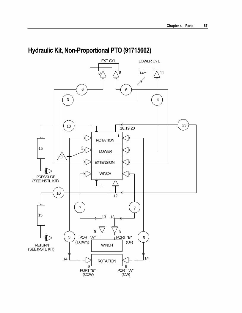
Chapter 4 Parts 87
Hydraulic Kit, Non-Proportional PTO (91715662)
EXT CYL LOWER CYL
8 8
6 6
3 4
14 11
10 23
15
PRESSURE(SEE INSTL KIT)
RETURN(SEE INSTL KIT)
10
15
12
18,19,20
ROTATION
LOWER
EXTENSION
WINCH
1
7 7
13 13
9 9
5 5 PORT "A"
(DOWN)
PORT "B"
(UP)WINCH
ROTATION14 14
9PORT "B"
(CCW)
9PORT "A"
(CW)
2
1
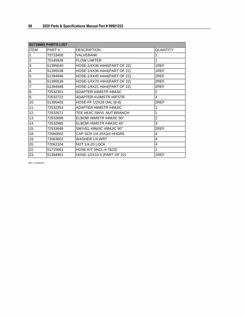
88 2020 Parts & Specifications Manual Part # 99901222
91715662 PARTS LIST
ITEM PART # DESCRIPTION QUANTITY
1. 70733400 VALVEBANK 1
2. 70145928 FLOW LIMITER 1
3. 51395540 HOSE-1/4X36 #4#6(PART OF 22) 1REF
4. 51395538 HOSE-1/4X36 #4#4(PART OF 22) 1REF
5. 51394946 HOSE-1/4X45 #4#4(PART OF 22) 2REF
6. 51395539 HOSE-1/4X70 #4#4(PART OF 22) 2REF
7. 51394948 HOSE-1/4X21 #4#4(PART OF 22) 2REF
8. 72532351 ADAPTER #4MSTR #4MJIC 2
9. 72532722 ADAPTER #10MSTR #6FSTR 4
10. 51395403 HOSE-FF 1/2X28 OAL (8-8) 2REF
11. 72532353 ADAPTER #6MSTR #4MJIC 1
12. 72532671 TEE #8JIC SWVL NUT BRANCH 1
13. 72532699 ELBOW #6MSTR #4MJIC 90° 2
14. 72532985 ELBOW #6MSTR #4MJIC 45° 3
15. 72533648 SWIVEL #8MJIC #8MJIC 90° 2REF
18. 72060002 CAP SCR 1/4-20X3/4 HHGR5 4
19. 72063001 WASHER 1/4 WRT 4
20. 72062104 NUT 1/4-20 LOCK 4
22. 51715663 HOSE KIT (INCL:4-7&23) 1
23. 51394951 HOSE-1/2X10.5 (PART OF 22) 1REF
REV. A 20040722
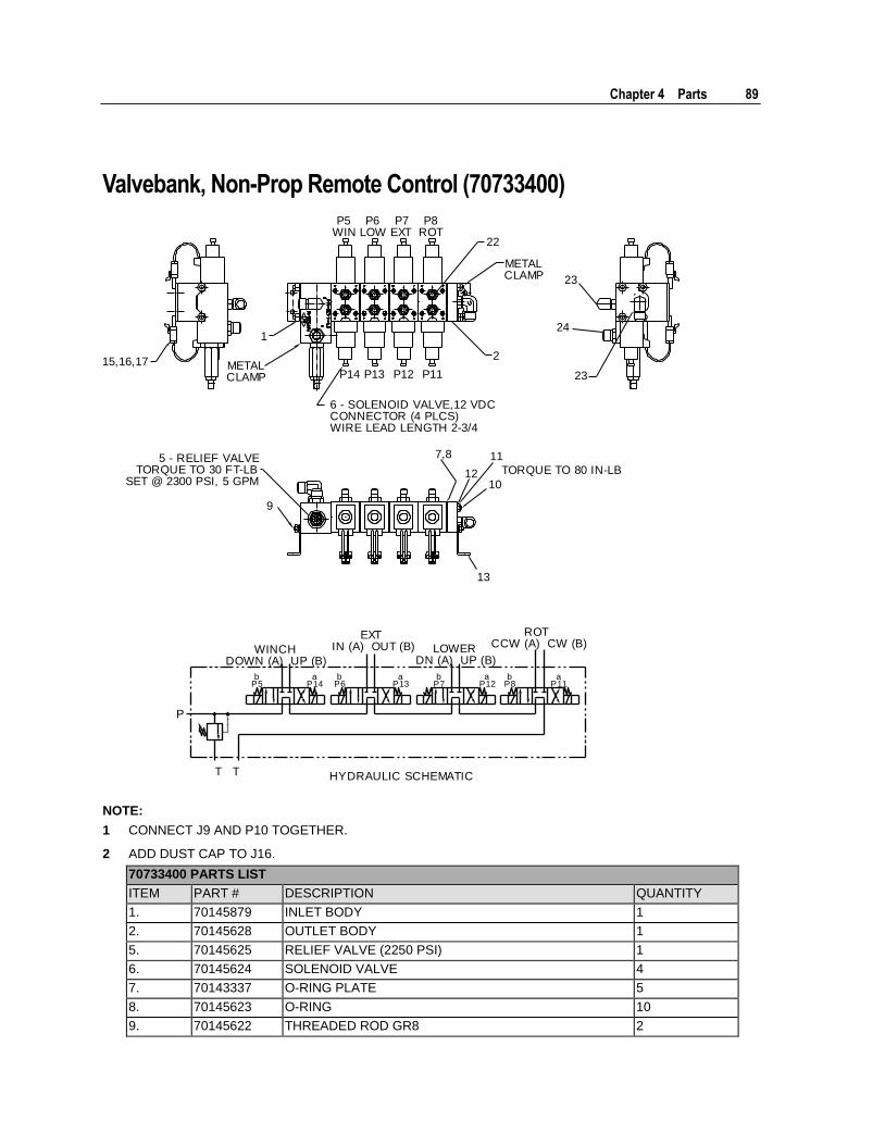
Chapter 4 Parts 89
Valvebank, Non-Prop Remote Control (70733400)
15,16,17
1
METALCLAMP
HYDRAULIC SCHEMATICT T
P
WINCHDOWN (A) UP (B)
EXTIN (A) OUT (B)
ROTCCW (A) CW (B)LOWER
DN (A) UP (B)
bP5
aP14
bP6
aP13
bP7
aP12
bP8
aP11
7,8
12
11
TORQUE TO 80 IN-LB
10
13
9
5 - RELIEF VALVETORQUE TO 30 FT-LB
SET @ 2300 PSI, 5 GPM
P5WIN
P8ROT
P6LOW
P7EXT
P14 P11P13 P12
6 - SOLENOID VALVE,12 VDCCONNECTOR (4 PLCS)WIRE LEAD LENGTH 2-3/4
2
METALCLAMP
22
24
23
23
NOTE:
1 CONNECT J9 AND P10 TOGETHER.
2 ADD DUST CAP TO J16.
70733400 PARTS LIST
ITEM PART # DESCRIPTION QUANTITY
1. 70145879 INLET BODY 1
2. 70145628 OUTLET BODY 1
5. 70145625 RELIEF VALVE (2250 PSI) 1
6. 70145624 SOLENOID VALVE 4
7. 70143337 O-RING PLATE 5
8. 70145623 O-RING 10
9. 70145622 THREADED ROD GR8 2
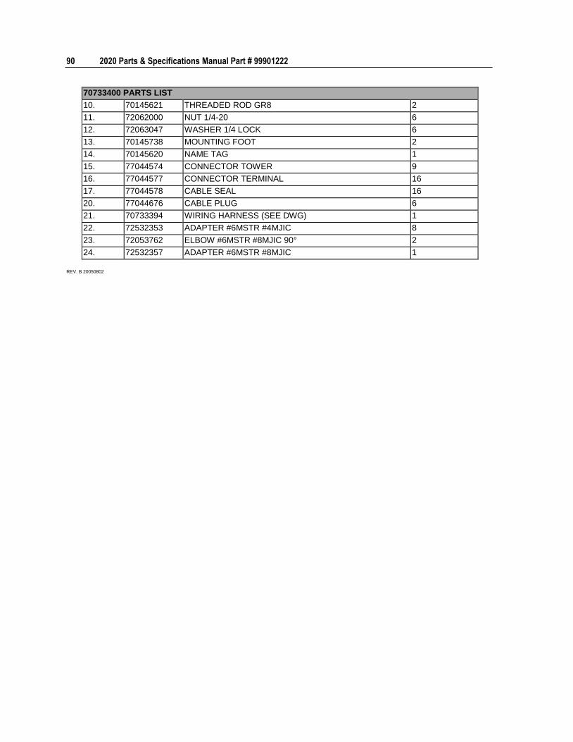
90 2020 Parts & Specifications Manual Part # 99901222
70733400 PARTS LIST
10. 70145621 THREADED ROD GR8 2
11. 72062000 NUT 1/4-20 6
12. 72063047 WASHER 1/4 LOCK 6
13. 70145738 MOUNTING FOOT 2
14. 70145620 NAME TAG 1
15. 77044574 CONNECTOR TOWER 9
16. 77044577 CONNECTOR TERMINAL 16
17. 77044578 CABLE SEAL 16
20. 77044676 CABLE PLUG 6
21. 70733394 WIRING HARNESS (SEE DWG) 1
22. 72532353 ADAPTER #6MSTR #4MJIC 8
23. 72053762 ELBOW #6MSTR #8MJIC 90° 2
24. 72532357 ADAPTER #6MSTR #8MJIC 1
REV. B 20050802
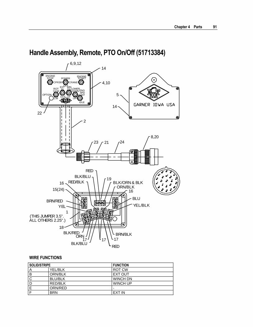
Chapter 4 Parts 91
Handle Assembly, Remote, PTO On/Off (51713384)
RED/BLK
BLK/BLU
RED
16
15(24)
BRN/RED
YEL
1(THIS JUMPER 3.5".ALL OTHERS 2.25".)
18
BLK/RED
BLK/BLU
ORN 17 17 17
RED
BRN/BLK
19BLK/ORN & BLK
ORN/BLK
YEL/BLK
16
BLU
22
4,10
14
6,9,12
ENGINESTOP POWER
OFF
CPRSR CRANE
ENGINESTART
OPTION
ROTCCW
CW
EXTIN
OUT
WINDN
UP
LOWERDOWN
UP
ENGSPD
FAST
IDLE
2
14
5
23 21 24
8,20
WIRE FUNCTIONS
SOLID/STRIPE FUNCTION
A YEL/BLK ROT CW
B ORN/BLK EXT OUT
C BLU/BLK WINCH DN
D RED/BLK WINCH UP
E ORN/RED -
F BRN EXT IN
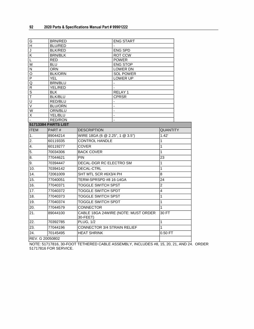
92 2020 Parts & Specifications Manual Part # 99901222
G BRN/RED ENG START
H BLU/RED -
J BLK/RED ENG SPD
K BRN/BLK ROT CCW
L RED POWER
M BLU ENG STOP
N ORN LOWER DN
O BLK/ORN SOL POWER
P YEL LOWER UP
Q BRN/BLU -
R YEL/RED -
S BLK RELAY 1
T BLK/BLU CPRSR
U RED/BLU -
V BLU/ORN -
W ORN/BLU -
X YEL/BLU -
- RED/RON -
51713384 PARTS LIST
ITEM PART # DESCRIPTION QUANTITY
1. 89044214 WIRE 18GA (6 @ 2.25", 1 @ 3.5") 1.42'
2. 60119335 CONTROL HANDLE 1
4. 60119277 COVER 1
5. 70034306 BACK COVER 1
8. 77044621 PIN 23
9. 70394447 DECAL-DGR RC ELECTRO SM 1
10. 70394142 DECAL-CTRL 1
14. 72061009 SHT MTL SCR #6X3/4 PH 8
15. 77040051 TERM-SPRSPD #8 16-14GA 24
16. 77040371 TOGGLE SWITCH SPST 2
17. 77040372 TOGGLE SWITCH SPDT 4
18. 77040373 TOGGLE SWITCH SPST 1
19. 77040374 TOGGLE SWITCH SPDT 1
20. 77044579 CONNECTOR 1
21. 89044100 CABLE 18GA 24WIRE (NOTE: MUST ORDER 30-FEET)
30 FT
22. 70392785 PLUG, 1/2 1
23. 77044196 CONNECTOR 3/4 STRAIN RELIEF 1
24. 70145495 HEAT SHRINK 0.50 FT
REV. G 20050802
NOTE: 51717816, 30-FOOT TETHERED CABLE ASSEMBLY, INCLUDES #8, 15, 20, 21, AND 24. ORDER 51717816 FOR SERVICE.
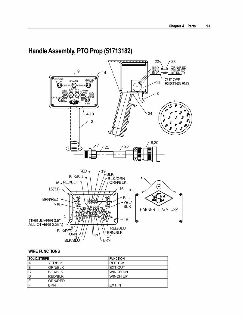
Chapter 4 Parts 93
Handle Assembly, PTO Prop (51713182)
RED/BLK
BLK/BLU
RED
16
15(31)
BRN/RED
YEL
1(THIS JUMPER 3.5".ALL OTHERS 2.25".)
18BLK/RED
BLK/BLU
ORN 17 17
BRN/BLK
19
BLK/ORNORN/BLK
YEL/BLK
16
BLU
BLK
18
RED/BLU
17BRN
9 14
4,10
2
721 25
ENGINESTOP POWER
OFF
CPRSR CRANE
ENGINESTART
OPTION
ROTCCW
CW
EXTIN
OUT
WNDN
UP
LOWERDOWN
UP
ENGSPD
FAST
IDLE
8,20
24
11
3
CUT OFFEXISTING END
REDGRNBLK
ORN/REDYEL/REDBLU/RED
22 23
WIRE FUNCTIONS
SOLID/STRIPE FUNCTION
A YEL/BLK ROT CW
B ORN/BLK EXT OUT
C BLU/BLK WINCH DN
D RED/BLK WINCH UP
E ORN/RED -
F BRN EXT IN
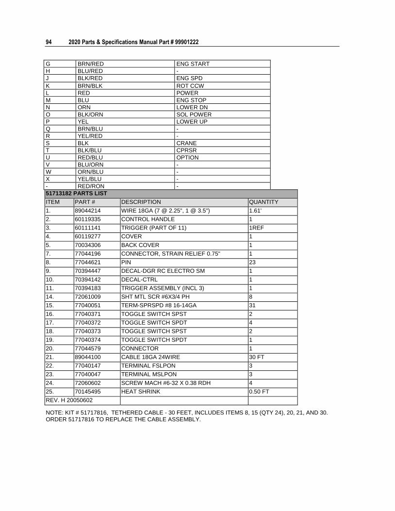
94 2020 Parts & Specifications Manual Part # 99901222
G BRN/RED ENG START
H BLU/RED -
J BLK/RED ENG SPD
K BRN/BLK ROT CCW
L RED POWER
M BLU ENG STOP
N ORN LOWER DN
O BLK/ORN SOL POWER
P YEL LOWER UP
Q BRN/BLU -
R YEL/RED -
S BLK CRANE
T BLK/BLU CPRSR
U RED/BLU OPTION
V BLU/ORN -
W ORN/BLU -
X YEL/BLU -
- RED/RON -
51713182 PARTS LIST
ITEM PART # DESCRIPTION QUANTITY
1. 89044214 WIRE 18GA (7 @ 2.25", 1 @ 3.5") 1.61'
2. 60119335 CONTROL HANDLE 1
3. 60111141 TRIGGER (PART OF 11) 1REF
4. 60119277 COVER 1
5. 70034306 BACK COVER 1
7. 77044196 CONNECTOR, STRAIN RELIEF 0.75" 1
8. 77044621 PIN 23
9. 70394447 DECAL-DGR RC ELECTRO SM 1
10. 70394142 DECAL-CTRL 1
11. 70394183 TRIGGER ASSEMBLY (INCL 3) 1
14. 72061009 SHT MTL SCR #6X3/4 PH 8
15. 77040051 TERM-SPRSPD #8 16-14GA 31
16. 77040371 TOGGLE SWITCH SPST 2
17. 77040372 TOGGLE SWITCH SPDT 4
18. 77040373 TOGGLE SWITCH SPST 2
19. 77040374 TOGGLE SWITCH SPDT 1
20. 77044579 CONNECTOR 1
21. 89044100 CABLE 18GA 24WIRE 30 FT
22. 77040147 TERMINAL FSLPON 3
23. 77040047 TERMINAL MSLPON 3
24. 72060602 SCREW MACH #6-32 X 0.38 RDH 4
25. 70145495 HEAT SHRINK 0.50 FT
REV. H 20050602
NOTE: KIT # 51717816, TETHERED CABLE - 30 FEET, INCLUDES ITEMS 8, 15 (QTY 24), 20, 21, AND 30. ORDER 51717816 TO REPLACE THE CABLE ASSEMBLY.
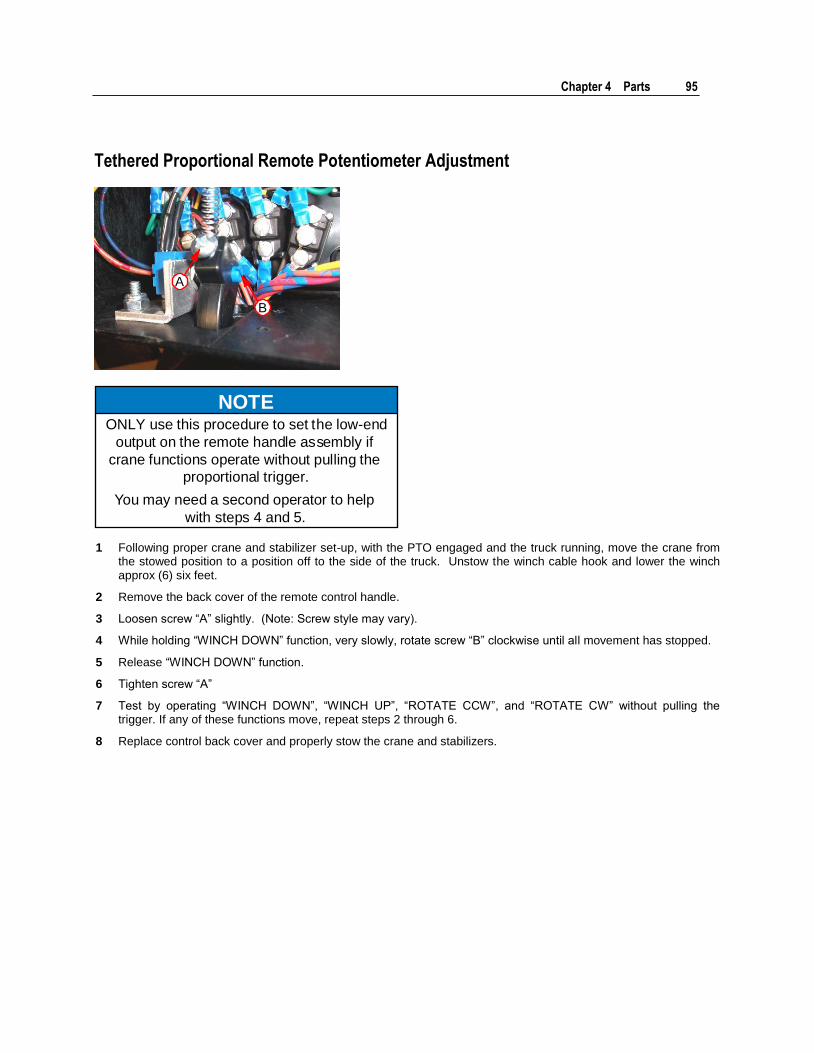
Chapter 4 Parts 95
Tethered Proportional Remote Potentiometer Adjustment
B
A
NOTEONLY use this procedure to set the low-end
output on the remote handle assembly if
crane functions operate without pulling the
proportional trigger.
You may need a second operator to help
with steps 4 and 5.
1 Following proper crane and stabilizer set-up, with the PTO engaged and the truck running, move the crane from the stowed position to a position off to the side of the truck. Unstow the winch cable hook and lower the winch approx (6) six feet.
2 Remove the back cover of the remote control handle.
3 Loosen screw “A” slightly. (Note: Screw style may vary).
4 While holding “WINCH DOWN” function, very slowly, rotate screw “B” clockwise until all movement has stopped.
5 Release “WINCH DOWN” function.
6 Tighten screw “A”
7 Test by operating “WINCH DOWN”, “WINCH UP”, “ROTATE CCW”, and “ROTATE CW” without pulling the trigger. If any of these functions move, repeat steps 2 through 6.
8 Replace control back cover and properly stow the crane and stabilizers.

96 2020 Parts & Specifications Manual Part # 99901222
Cable Assembly, Tethered Remote (70733394)
J15
J5J7J6 J8 R1
P2
P1
P3 J4
J14J13 J12 J11
J9
P16 J17
P10
1(10)
3(20)5(20)
8(1)
11(4)12(1)
2
4(2)5(2)
103(4)
5(4)
9
4(4)5(4)
CONNEC TOR (1)TERMINAL (7)
WEDGE (1)CAV. PLUG (1)
67(23)
70733394 PARTS LIST
ITEM PART # DESCRIPTION QUANTITY
1. 77044573 SHROUD CONN 2-CONTACT 10REF
2. 77044574 TOWER CONN 2REF
3. 77044576 TERMINAL-M 24REF
4. 77044577 TERMINAL-F 8REF
5. 77044578 CABLE SEAL 32REF
6. 77044620 CONN RCPT 1REF
7. 77044580 SOCKET 23REF
8. SOCKET, RELAY 1REF
9. 77044623 TOWER CONN 4-CONTACT 1REF
10. 77044624 SHROUD CONN 4-CONTACT 1REF
11. TERMINAL 4REF
12. RELAY 1REF
REV. F 20040205
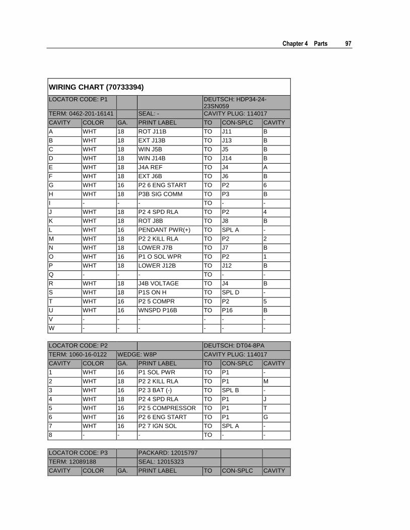
Chapter 4 Parts 97
WIRING CHART (70733394)
LOCATOR CODE: P1 DEUTSCH: HDP34-24-23SN059
TERM: 0462-201-16141 SEAL: - CAVITY PLUG: 114017
CAVITY COLOR GA. PRINT LABEL TO CON-SPLC CAVITY
A WHT 18 ROT J11B TO J11 B
B WHT 18 EXT J13B TO J13 B
C WHT 18 WIN J5B TO J5 B
D WHT 18 WIN J14B TO J14 B
E WHT 18 J4A REF TO J4 A
F WHT 18 EXT J6B TO J6 B
G WHT 16 P2 6 ENG START TO P2 6
H WHT 18 P3B SIG COMM TO P3 B
I - - - TO - -
J WHT 18 P2 4 SPD RLA TO P2 4
K WHT 18 ROT J8B TO J8 B
L WHT 16 PENDANT PWR(+) TO SPL A -
M WHT 18 P2 2 KILL RLA TO P2 2
N WHT 18 LOWER J7B TO J7 B
O WHT 16 P1 O SOL WPR TO P2 1
P WHT 18 LOWER J12B TO J12 B
Q - - - TO - -
R WHT 18 J4B VOLTAGE TO J4 B
S WHT 18 P1S ON H TO SPL D -
T WHT 16 P2 5 COMPR TO P2 5
U WHT 16 WNSPD P16B TO P16 B
V - - - - - -
W - - - - - -
LOCATOR CODE: P2 DEUTSCH: DT04-8PA
TERM: 1060-16-0122 WEDGE: W8P CAVITY PLUG: 114017
CAVITY COLOR GA. PRINT LABEL TO CON-SPLC CAVITY
1 WHT 16 P1 SOL PWR TO P1 -
2 WHT 18 P2 2 KILL RLA TO P1 M
3 WHT 16 P2 3 BAT (-) TO SPL B -
4 WHT 18 P2 4 SPD RLA TO P1 J
5 WHT 16 P2 5 COMPRESSOR TO P1 T
6 WHT 16 P2 6 ENG START TO P1 G
7 WHT 16 P2 7 IGN SOL TO SPL A -
8 - - - TO - -
LOCATOR CODE: P3 PACKARD: 12015797
TERM: 12089188 SEAL: 12015323
CAVITY COLOR GA. PRINT LABEL TO CON-SPLC CAVITY
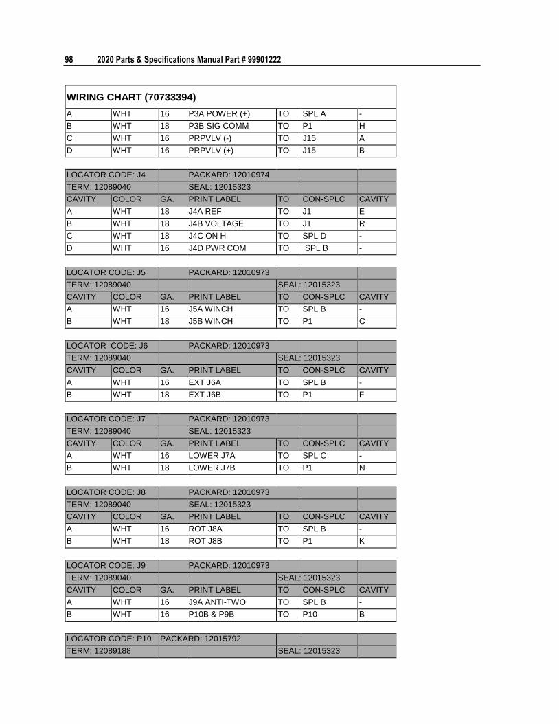
98 2020 Parts & Specifications Manual Part # 99901222
WIRING CHART (70733394)
A WHT 16 P3A POWER (+) TO SPL A -
B WHT 18 P3B SIG COMM TO P1 H
C WHT 16 PRPVLV (-) TO J15 A
D WHT 16 PRPVLV (+) TO J15 B
LOCATOR CODE: J4 PACKARD: 12010974
TERM: 12089040 SEAL: 12015323
CAVITY COLOR GA. PRINT LABEL TO CON-SPLC CAVITY
A WHT 18 J4A REF TO J1 E
B WHT 18 J4B VOLTAGE TO J1 R
C WHT 18 J4C ON H TO SPL D -
D WHT 16 J4D PWR COM TO SPL B -
LOCATOR CODE: J5 PACKARD: 12010973
TERM: 12089040 SEAL: 12015323
CAVITY COLOR GA. PRINT LABEL TO CON-SPLC CAVITY
A WHT 16 J5A WINCH TO SPL B -
B WHT 18 J5B WINCH TO P1 C
LOCATOR CODE: J6 PACKARD: 12010973
TERM: 12089040 SEAL: 12015323
CAVITY COLOR GA. PRINT LABEL TO CON-SPLC CAVITY
A WHT 16 EXT J6A TO SPL B -
B WHT 18 EXT J6B TO P1 F
LOCATOR CODE: J7 PACKARD: 12010973
TERM: 12089040 SEAL: 12015323
CAVITY COLOR GA. PRINT LABEL TO CON-SPLC CAVITY
A WHT 16 LOWER J7A TO SPL C -
B WHT 18 LOWER J7B TO P1 N
LOCATOR CODE: J8 PACKARD: 12010973
TERM: 12089040 SEAL: 12015323
CAVITY COLOR GA. PRINT LABEL TO CON-SPLC CAVITY
A WHT 16 ROT J8A TO SPL B -
B WHT 18 ROT J8B TO P1 K
LOCATOR CODE: J9 PACKARD: 12010973
TERM: 12089040 SEAL: 12015323
CAVITY COLOR GA. PRINT LABEL TO CON-SPLC CAVITY
A WHT 16 J9A ANTI-TWO TO SPL B -
B WHT 16 P10B & P9B TO P10 B
LOCATOR CODE: P10 PACKARD: 12015792
TERM: 12089188 SEAL: 12015323
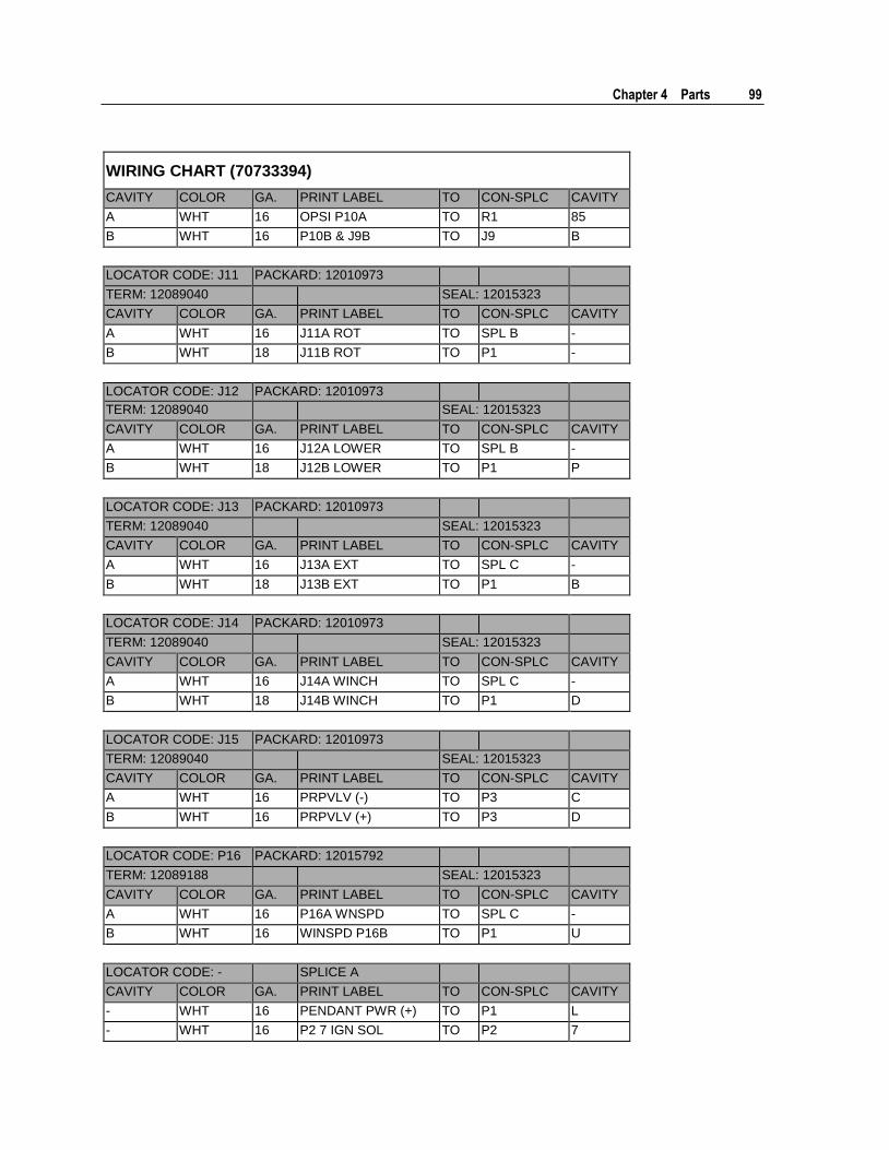
Chapter 4 Parts 99
WIRING CHART (70733394)
CAVITY COLOR GA. PRINT LABEL TO CON-SPLC CAVITY
A WHT 16 OPSI P10A TO R1 85
B WHT 16 P10B & J9B TO J9 B
LOCATOR CODE: J11 PACKARD: 12010973
TERM: 12089040 SEAL: 12015323
CAVITY COLOR GA. PRINT LABEL TO CON-SPLC CAVITY
A WHT 16 J11A ROT TO SPL B -
B WHT 18 J11B ROT TO P1 -
LOCATOR CODE: J12 PACKARD: 12010973
TERM: 12089040 SEAL: 12015323
CAVITY COLOR GA. PRINT LABEL TO CON-SPLC CAVITY
A WHT 16 J12A LOWER TO SPL B -
B WHT 18 J12B LOWER TO P1 P
LOCATOR CODE: J13 PACKARD: 12010973
TERM: 12089040 SEAL: 12015323
CAVITY COLOR GA. PRINT LABEL TO CON-SPLC CAVITY
A WHT 16 J13A EXT TO SPL C -
B WHT 18 J13B EXT TO P1 B
LOCATOR CODE: J14 PACKARD: 12010973
TERM: 12089040 SEAL: 12015323
CAVITY COLOR GA. PRINT LABEL TO CON-SPLC CAVITY
A WHT 16 J14A WINCH TO SPL C -
B WHT 18 J14B WINCH TO P1 D
LOCATOR CODE: J15 PACKARD: 12010973
TERM: 12089040 SEAL: 12015323
CAVITY COLOR GA. PRINT LABEL TO CON-SPLC CAVITY
A WHT 16 PRPVLV (-) TO P3 C
B WHT 16 PRPVLV (+) TO P3 D
LOCATOR CODE: P16 PACKARD: 12015792
TERM: 12089188 SEAL: 12015323
CAVITY COLOR GA. PRINT LABEL TO CON-SPLC CAVITY
A WHT 16 P16A WNSPD TO SPL C -
B WHT 16 WINSPD P16B TO P1 U
LOCATOR CODE: - SPLICE A
CAVITY COLOR GA. PRINT LABEL TO CON-SPLC CAVITY
- WHT 16 PENDANT PWR (+) TO P1 L
- WHT 16 P2 7 IGN SOL TO P2 7
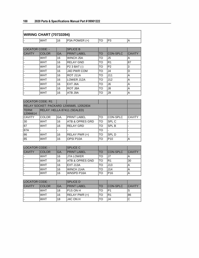
100 2020 Parts & Specifications Manual Part # 99901222
WIRING CHART (70733394)
- WHT 16 P3A POWER (+) TO P3 A
LOCATOR CODE: - SPLICE B
CAVITY COLOR GA. PRINT LABEL TO CON-SPLC CAVITY
- WHT 16 WINCH J5A TO J5 A
- WHT 16 RELAY GND TO R1 87
- WHT 16 P2 3 BAT (-) TO P2 3
- WHT 16 J4D PWR COM TO J4 D
- WHT 16 ROT J11A TO J11 A
- WHT 16 LOWER J12A TO J12 A
- WHT 16 EXT J6A TO J6 A
- WHT 16 ROT J8A TO J8 A
- WHT 16 ATB J9A TO J9 A
LOCATOR CODE: R1
RELAY SOCKET: PACKARD 12065685, 12052834
TERM: 12066614
RELAY: HELLA 87411 (SEALED)
CAVITY COLOR GA. PRINT LABEL TO CON-SPLC CAVITY
30 WHT 16 ATB & OPRES GRD TO SPL C -
87 WHT 16 RELAY GRD TO SPL B -
87A - - - TO - -
86 WHT 16 RELAY PWR (+) TO SPL D -
85 WHT 16 OPSI P10A TO P10 A
LOCATOR CODE: - SPLICE C
CAVITY COLOR GA. PRINT LABEL TO CON-SPLC CAVITY
- WHT 16 J7A LOWER TO J7 A
- WHT 16 ATB & OPRES GND TO R1 30
- WHT 16 EXT J13A TO J13 A
- WHT 16 WINCH J14A TO J14 A
- WHT 16 WNSPD P16A TO P16 A
LOCATOR CODE: - SPLICE D
CAVITY COLOR GA. PRINT LABEL TO CON-SPLC CAVITY
- WHT 18 P1S ON H TO P1 S
- WHT 16 RELAY PWR (+) TO R1 86
- WHT 18 J4C ON H TO J4 C
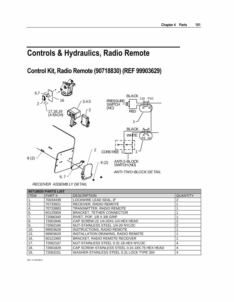
Chapter 4 Parts 101
Controls & Hydraulics, Radio Remote
Control Kit, Radio Remote (90718830) (REF 99903629)
6,7
2
17,18,19(4 EACH)
3,4,5
2
PRESSURESWITCH(NC)
BLACK
BLACK
CORD REE L
ANTI-2-BLOCKSWITCH (NO)
ANTI-TWO-BLOCK DETAIL
1
B B
A AP9 J9
J10 P10A A
B B
RED
WHITE
1
16
2
8 (2)
6, 7
9 (2)
RECEIVER ASSEMB LY DETAIL
90718830 PARTS LIST
ITEM PART # DESCRIPTION QUANTITY
1. 70034439 LOCKWIRE LEAD SEAL, 8" 2
2. 70733921 RECEIVER, RADIO REMOTE 1
4. 70733883 TRANSMITTER, RADIO REMOTE 1
6. 60125959 BRACKET, TETHER CONNECTOR 1
7. 72066340 RIVET, POP, 1/8 X 3/8 GRIP 1
8. 72601846 CAP SCREW-22 1/4-20X1-1/4 HEX HEAD 2
9. 72062194 NUT-STAINLESS STEEL 1/4-20 NYLOC 2
10. 99903628 INSTRUCTIONS, RADIO REMOTE 1
13. 99903629 INSTALLATION DRAWING, RADIO REMOTE 1
16. 60121960 BRACKET, RADIO REMOTE RECEIVER 1
17. 72062167 NUT-STAINLESS STEEL 0.31-18 HEX NYLOC 4
18. 72601829 CAP SCREW-STAINLESS STEEL 0.31-18X.75 HEX HEAD 4
19. 72063151 WASHER-STAINLESS STEEL 0.31 LOCK TYPE 304 4
REV. D 20140612
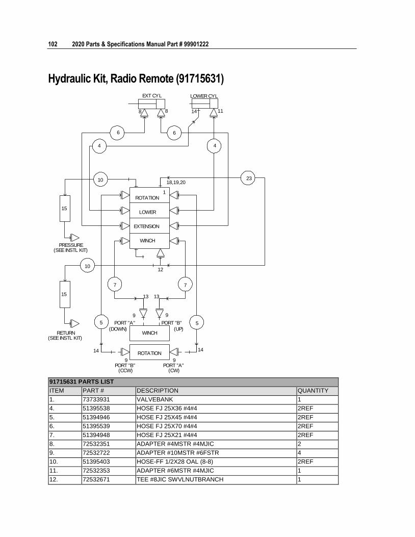
102 2020 Parts & Specifications Manual Part # 99901222
Hydraulic Kit, Radio Remote (91715631)
EXT CYL LOWER CYL
8 8
6 6
4 4
14 11
10 23
15
PRESSURE(SEE INSTL KIT)
RETURN(SEE INSTL KIT)
10
15
12
18,19,20
ROTATION
LOWER
EXTENSION
WINCH
1
7 7
13 13
9 9
5 5 PORT "A"
(DOWN)
PORT "B"
(UP)WINCH
ROTATION14 14
9PORT "B"
(CCW)
9PORT "A"
(CW)
91715631 PARTS LIST
ITEM PART # DESCRIPTION QUANTITY
1. 73733931 VALVEBANK 1
4. 51395538 HOSE FJ 25X36 #4#4 2REF
5. 51394946 HOSE FJ 25X45 #4#4 2REF
6. 51395539 HOSE FJ 25X70 #4#4 2REF
7. 51394948 HOSE FJ 25X21 #4#4 2REF
8. 72532351 ADAPTER #4MSTR #4MJIC 2
9. 72532722 ADAPTER #10MSTR #6FSTR 4
10. 51395403 HOSE-FF 1/2X28 OAL (8-8) 2REF
11. 72532353 ADAPTER #6MSTR #4MJIC 1
12. 72532671 TEE #8JIC SWVLNUTBRANCH 1
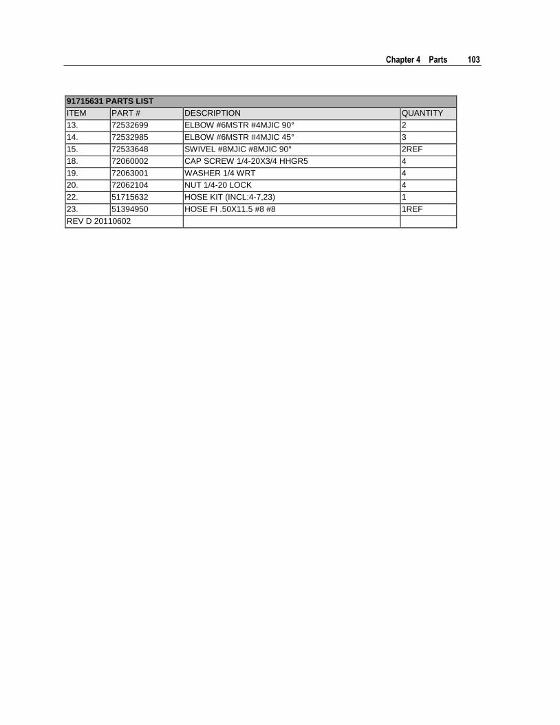
Chapter 4 Parts 103
91715631 PARTS LIST
ITEM PART # DESCRIPTION QUANTITY
13. 72532699 ELBOW #6MSTR #4MJIC 90° 2
14. 72532985 ELBOW #6MSTR #4MJIC 45° 3
15. 72533648 SWIVEL #8MJIC #8MJIC 90° 2REF
18. 72060002 CAP SCREW 1/4-20X3/4 HHGR5 4
19. 72063001 WASHER 1/4 WRT 4
20. 72062104 NUT 1/4-20 LOCK 4
22. 51715632 HOSE KIT (INCL:4-7,23) 1
23. 51394950 HOSE FI .50X11.5 #8 #8 1REF
REV D 20110602
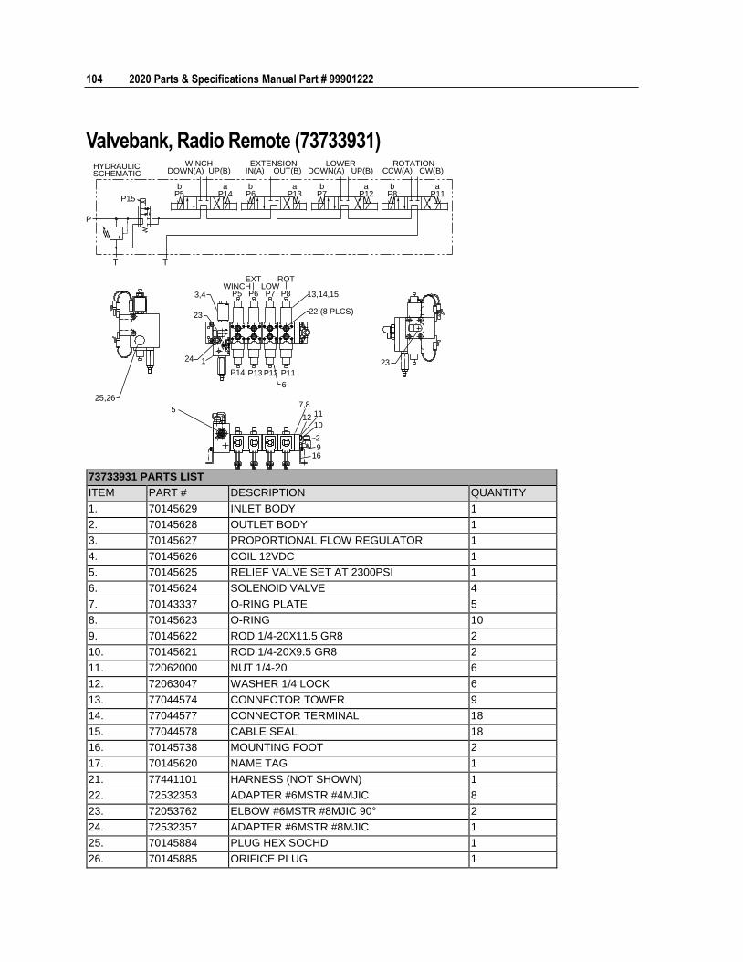
104 2020 Parts & Specifications Manual Part # 99901222
Valvebank, Radio Remote (73733931) WINCH
DOWN(A) UP(B)EXTENSION
IN(A) OUT(B)LOWER
DOWN(A) UP(B)ROTATION
CCW(A) CW(B)
bP5
aP14
bP6
aP13
bP7
aP12
bP8
aP11
P15
TT
P
HYDRAULICSCHEMATIC
3,4WINCH
P5
EXT
P6LOWP7
ROT
P8 13,14,15
22 (8 PLCS)23
24 1
P14 P13 P12 P11
6
23
7,8
12 11
10
29
16
5
25,26
73733931 PARTS LIST
ITEM PART # DESCRIPTION QUANTITY
1. 70145629 INLET BODY 1
2. 70145628 OUTLET BODY 1
3. 70145627 PROPORTIONAL FLOW REGULATOR 1
4. 70145626 COIL 12VDC 1
5. 70145625 RELIEF VALVE SET AT 2300PSI 1
6. 70145624 SOLENOID VALVE 4
7. 70143337 O-RING PLATE 5
8. 70145623 O-RING 10
9. 70145622 ROD 1/4-20X11.5 GR8 2
10. 70145621 ROD 1/4-20X9.5 GR8 2
11. 72062000 NUT 1/4-20 6
12. 72063047 WASHER 1/4 LOCK 6
13. 77044574 CONNECTOR TOWER 9
14. 77044577 CONNECTOR TERMINAL 18
15. 77044578 CABLE SEAL 18
16. 70145738 MOUNTING FOOT 2
17. 70145620 NAME TAG 1
21. 77441101 HARNESS (NOT SHOWN) 1
22. 72532353 ADAPTER #6MSTR #4MJIC 8
23. 72053762 ELBOW #6MSTR #8MJIC 90° 2
24. 72532357 ADAPTER #6MSTR #8MJIC 1
25. 70145884 PLUG HEX SOCHD 1
26. 70145885 ORIFICE PLUG 1
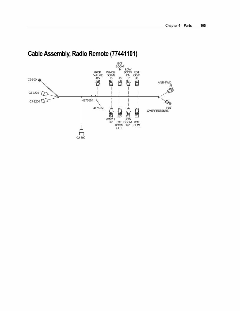
Chapter 4 Parts 105
Cable Assembly, Radio Remote (77441101)
BA BA A B ABA B
AB
PROPVALVE
J15
WINCHDOWN
J5
EXTBOOM
IN
J6
LOWBOOM
DNJ7
ROTCCW
J8
ANTI-TWOJ9
P10OVERPRESSURE
J14WINCH
UP
J12LOW
BOOMUP
J13
EXTBOOMOUT
J11
ROTCCW
CJ-800
4175554
4175552
CJ-500
CJ-1201
CJ-1200
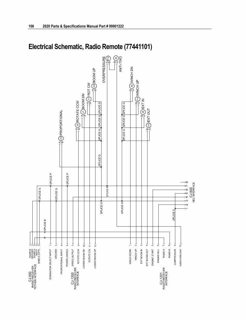
106 2020 Parts & Specifications Manual Part # 99901222
Electrical Schematic, Radio Remote (77441101)
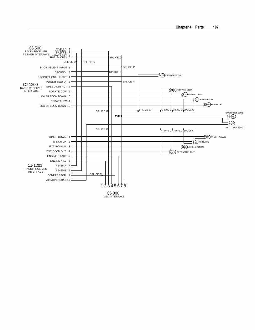
Chapter 4 Parts 107
BA
BA
AB
BA
BA
BA
AB
AB
AB
AB
BA
CJ-500RADIO RECEIVER
TETHER INTERFACE
CJ-1200RADIO RECEIVER
INTERFACE
CJ-1201RADIO RECEIVER
INTERFACE
WINCH DOWN
WINCH UP
EXT BOOM IN
EXT BOOM OUT
ENGINE START
ENGINE KILL
RS485 A
RS485 B
COMPRESSOR
A2B/OVERLOAD
1
2
3
4
5
6
7
8
9
12
BODY SELECT INPUT
GROUND
PROPORTIONAL INPUT
POWER (RADIO)
SPEED OUTPUT
ROTATE CCW
LOWER BOOM DOWN
ROTATE CW
LOWER BOOM DOWN
1
3
4
6
7
9
10
11
12
RS485 BGROUNDRS485 A
+ BATTERYSHIELD (OPT)
12345
SPLICE D SPLICE B
SPLICE G
SPLICE G
SPLICE P
SPLICE P
SPLICE G
SPLICE G
SPLICE G SPLICE G SPLICE G SPLICE G
SPLICE G SPLICE G SPLICE G
SPLICE C
CJ-800VEC INTERFACE
1 2 3 4 5 6 7 8
J14 WINCH UP
J13 EXTENSION OUT
J6 EXTENSION IN
J5 WINCH DOW N
J9
ANTI-TWO BLOCK
P10
OVERPRESSURE
J12 BOOM UP
J11 ROTATE CW
J7 BOOM DOWN
J8 ROTATE CCW
J15 PROPORTIONAL

108 2020 Parts & Specifications Manual Part # 99901222
Stabilizers (Reference 99905457 Auxiliary Stabilizer Manual)
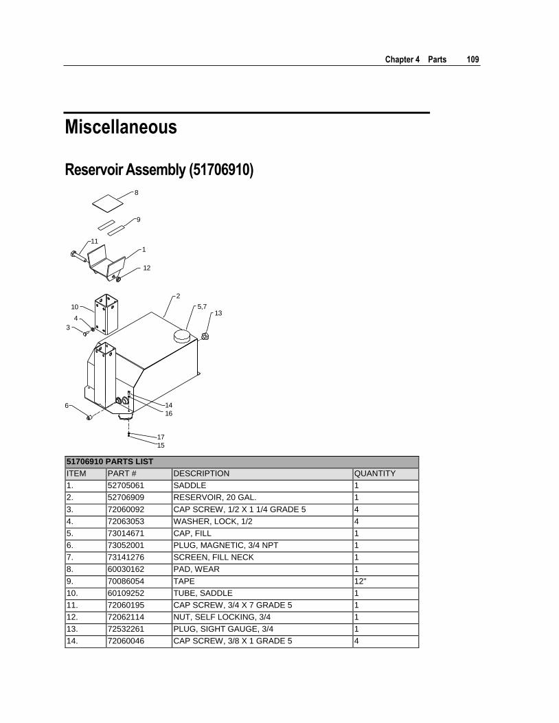
Chapter 4 Parts 109
Miscellaneous
Reservoir Assembly (51706910)
135,7
2
1
12
10
4
3
6 14
16
17
15
9
11
8
51706910 PARTS LIST
ITEM PART # DESCRIPTION QUANTITY
1. 52705061 SADDLE 1
2. 52706909 RESERVOIR, 20 GAL. 1
3. 72060092 CAP SCREW, 1/2 X 1 1/4 GRADE 5 4
4. 72063053 WASHER, LOCK, 1/2 4
5. 73014671 CAP, FILL 1
6. 73052001 PLUG, MAGNETIC, 3/4 NPT 1
7. 73141276 SCREEN, FILL NECK 1
8. 60030162 PAD, WEAR 1
9. 70086054 TAPE 12"
10. 60109252 TUBE, SADDLE 1
11. 72060195 CAP SCREW, 3/4 X 7 GRADE 5 1
12. 72062114 NUT, SELF LOCKING, 3/4 1
13. 72532261 PLUG, SIGHT GAUGE, 3/4 1
14. 72060046 CAP SCREW, 3/8 X 1 GRADE 5 4
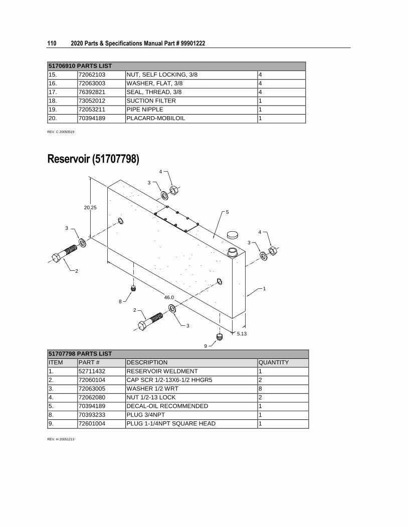
110 2020 Parts & Specifications Manual Part # 99901222
51706910 PARTS LIST
15. 72062103 NUT, SELF LOCKING, 3/8 4
16. 72063003 WASHER, FLAT, 3/8 4
17. 76392821 SEAL, THREAD, 3/8 4
18. 73052012 SUCTION FILTER 1
19. 72053211 PIPE NIPPLE 1
20. 70394189 PLACARD-MOBILOIL 1
REV. C 20050519
Reservoir (51707798)
2
8
2
3
20.255
3
4
5.13
3
46.0
1
3
4
9 51707798 PARTS LIST
ITEM PART # DESCRIPTION QUANTITY
1. 52711432 RESERVOIR WELDMENT 1
2. 72060104 CAP SCR 1/2-13X6-1/2 HHGR5 2
3. 72063005 WASHER 1/2 WRT 8
4. 72062080 NUT 1/2-13 LOCK 2
5. 70394189 DECAL-OIL RECOMMENDED 1
8. 70393233 PLUG 3/4NPT 1
9. 72601004 PLUG 1-1/4NPT SQUARE HEAD 1
REV. H 20051213
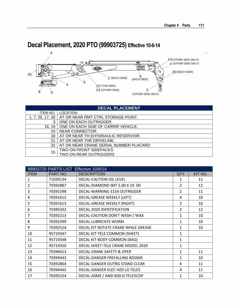
Chapter 4 Parts 111
Decal Placement, 2020 PTO (99903725) Effective 10-6-14
8 9
45
52223
25
4
26
20
14
4
(THIS SIDE)
(OTHER SIDE)
(EACH SIDE) (EACH SIDE)
(OTHER SIDE ONLY)
(EACH SIDE)
(OTHER SIDE ONLY)
(OTHER SIDE ONLY)
DECAL PLACEMENT ITEM NO. LOCATION
1, 7, 25, 17, 26 AT OR NEAR RMT CTRL STORAGE POINT.
3 ONE ON EACH OUTRIGGER.
16, 19 ONE ON EACH SIDE OF CARRIR VEHICLE.
24 NEAR CONNECTOR.
18 AT OR NEAR TH EHYDRAULIC RESERVOIR.
21 AT OR NEAR THE DRIVELINE.
32 AT OR NEAR CRANE SERIAL NUMBER PLACARD
15 TWO ON FRONT SIDEPACKS TWO ON REAR OUTRIGGERS
99903725 PARTS LIST Effective 10/6/14 ITEM PART NO. DESCRIPTION QTY KIT NO.
1 71039134 DECAL-CAUTION OIL LEVEL 1 11
2 70392887 DECAL-DIAMOND IMT 5.00 X 10. 00 2 12
3 70391598 DECAL-WARNING 315A OUTRIGGER 2 11
4 70391612 DECAL-GREASE WEEKLY (LEFT) 4 10
5 70391613 DECAL-GREASE WEEKLY (RIGHT) 2 10
6 70395332 DECAL-2020 IDENTIFICATION 2 12
7 70392213 DECAL-CAUTION DON'T WASH / WAX 1 10
8 70392399 DECAL-LUBRICATE WORM 1 10
9 70392524 DECAL KIT-ROTATE CRANE WHILE GREASE 1 10
10 95719347 DECAL KIT-TELE COMMON (SHEET) 1
11 95719348 DECAL KIT-BODY COMMON (BAG) 1
12 95719350 DECAL SHEET-TELE CRANE MODEL 2020 1
13 70396613 DECAL-CRANE SAFETY & OPER 1 11
14 70394443 DECAL-DANGER FREFALLING BOOMS 1 10
15 70392864 DECAL-DANGER OUTRG STAND CLEAR 4 11
16 70394445 DECAL-DANGER ELEC HZD LG TELES 4 11
17 70395324 DECAL-ASME / ANSI B30.D-TELESCOP 1 10
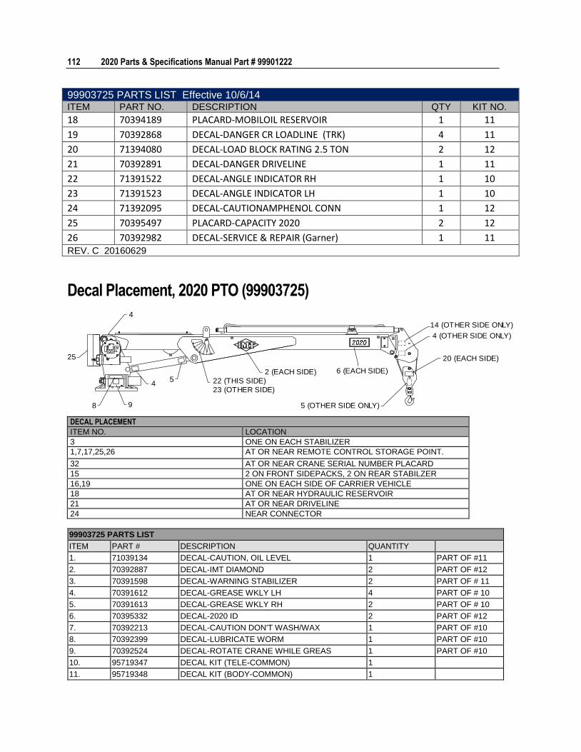
112 2020 Parts & Specifications Manual Part # 99901222
99903725 PARTS LIST Effective 10/6/14 ITEM PART NO. DESCRIPTION QTY KIT NO.
18 70394189 PLACARD-MOBILOIL RESERVOIR 1 11
19 70392868 DECAL-DANGER CR LOADLINE (TRK) 4 11
20 71394080 DECAL-LOAD BLOCK RATING 2.5 TON 2 12
21 70392891 DECAL-DANGER DRIVELINE 1 11
22 71391522 DECAL-ANGLE INDICATOR RH 1 10
23 71391523 DECAL-ANGLE INDICATOR LH 1 10
24 71392095 DECAL-CAUTIONAMPHENOL CONN 1 12
25 70395497 PLACARD-CAPACITY 2020 2 12
26 70392982 DECAL-SERVICE & REPAIR (Garner) 1 11 REV. C 20160629
Decal Placement, 2020 PTO (99903725)
4
25
8 9
45 22 (THIS SIDE)
23 (OTHER SIDE)
2 (EACH SIDE)
14 (OTHER SIDE ONLY)
4 (OTHER SIDE ONLY)
20 (EACH SIDE)
6 (EACH SIDE)
5 (OTHER SIDE ONLY)
DECAL PLACEMENT
ITEM NO. LOCATION
3 ONE ON EACH STABILIZER
1,7,17,25,26 AT OR NEAR REMOTE CONTROL STORAGE POINT.
32 AT OR NEAR CRANE SERIAL NUMBER PLACARD
15 2 ON FRONT SIDEPACKS, 2 ON REAR STABILZER
16,19 ONE ON EACH SIDE OF CARRIER VEHICLE
18 AT OR NEAR HYDRAULIC RESERVOIR
21 AT OR NEAR DRIVELINE
24 NEAR CONNECTOR
99903725 PARTS LIST
ITEM PART # DESCRIPTION QUANTITY
1. 71039134 DECAL-CAUTION, OIL LEVEL 1 PART OF #11
2. 70392887 DECAL-IMT DIAMOND 2 PART OF #12
3. 70391598 DECAL-WARNING STABILIZER 2 PART OF # 11
4. 70391612 DECAL-GREASE WKLY LH 4 PART OF # 10
5. 70391613 DECAL-GREASE WKLY RH 2 PART OF # 10
6. 70395332 DECAL-2020 ID 2 PART OF #12
7. 70392213 DECAL-CAUTION DON'T WASH/WAX 1 PART OF #10
8. 70392399 DECAL-LUBRICATE WORM 1 PART OF #10
9. 70392524 DECAL-ROTATE CRANE WHILE GREAS 1 PART OF #10
10. 95719347 DECAL KIT (TELE-COMMON) 1
11. 95719348 DECAL KIT (BODY-COMMON) 1
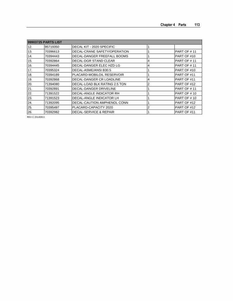
Chapter 4 Parts 113
99903725 PARTS LIST
12. 95719350 DECAL KIT - 2020 SPECIFIC 1
13. 70396613 DECAL-CRANE SAFETY/OPERATION 1 PART OF # 11
14. 70394443 DECAL-DANGER FREEFALL BOOMS 1 PART OF #10
15. 70392864 DECAL-DGR STAND CLEAR 4 PART OF # 11
16. 70394445 DECAL-DANGER ELEC HZD LG 4 PART OF # 11
17. 70395324 DECAL-ASME/ANSI B30.5 1 PART OF #10
18. 70394189 PLACARD-MOBILOIL RESERVOIR 1 PART OF #11
19. 70392868 DECAL-DANGER CR LOADLINE 4 PART OF #11
20. 71394080 DECAL-LOAD BLK RATING 2.5 TON 2 PART OF #12
21. 70392891 DECAL-DANGER DRIVELINE 1 PART OF # 11
22. 71391522 DECAL-ANGLE INDICATOR RH 1 PART OF # 10
23. 71391523 DECAL-ANGLE INDICATOR LH 1 PART OF # 10
24. 71392095 DECAL-CAUTION AMPHENOL CONN 1 PART OF #12
25. 70395497 PLACARD-CAPACITY 2020 2 PART OF #12
26. 70392982 DECAL-SERVICE & REPAIR 1 PART OF #11
REV C 20140911
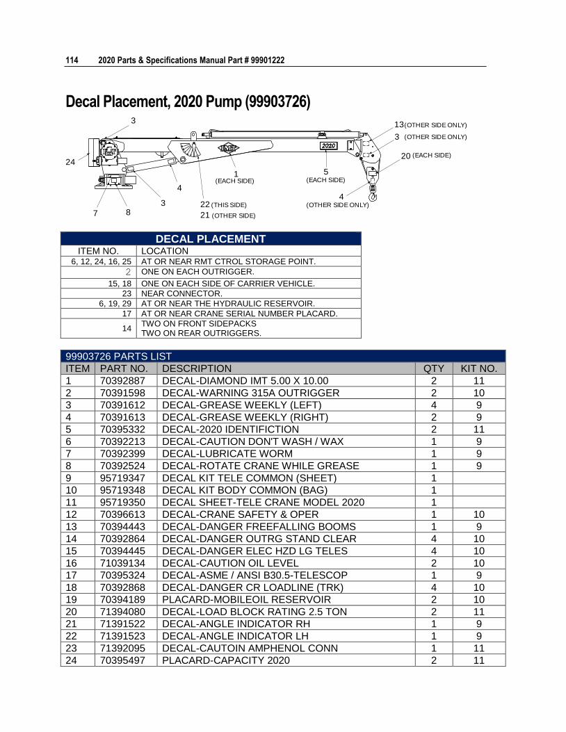
114 2020 Parts & Specifications Manual Part # 99901222
Decal Placement, 2020 Pump (99903726)
4
24
3
7 83
21
22
1 5
4
13
3
20
(OTHER SIDE ONLY)
(OTHER SIDE ONLY)
(EACH SIDE)
(EACH SIDE)(EACH SIDE)
(OTHER SIDE ONLY)(THIS SIDE)
(OTHER SIDE)
DECAL PLACEMENT ITEM NO. LOCATION
6, 12, 24, 16, 25 AT OR NEAR RMT CTROL STORAGE POINT.
2 ONE ON EACH OUTRIGGER.
15, 18 ONE ON EACH SIDE OF CARRIER VEHICLE.
23 NEAR CONNECTOR.
6, 19, 29 AT OR NEAR THE HYDRAULIC RESERVOIR.
17 AT OR NEAR CRANE SERIAL NUMBER PLACARD.
14 TWO ON FRONT SIDEPACKS TWO ON REAR OUTRIGGERS.
99903726 PARTS LIST
ITEM PART NO. DESCRIPTION QTY KIT NO.
1 70392887 DECAL-DIAMOND IMT 5.00 X 10.00 2 11
2 70391598 DECAL-WARNING 315A OUTRIGGER 2 10
3 70391612 DECAL-GREASE WEEKLY (LEFT) 4 9
4 70391613 DECAL-GREASE WEEKLY (RIGHT) 2 9
5 70395332 DECAL-2020 IDENTIFICTION 2 11
6 70392213 DECAL-CAUTION DON'T WASH / WAX 1 9
7 70392399 DECAL-LUBRICATE WORM 1 9
8 70392524 DECAL-ROTATE CRANE WHILE GREASE 1 9
9 95719347 DECAL KIT TELE COMMON (SHEET) 1
10 95719348 DECAL KIT BODY COMMON (BAG) 1
11 95719350 DECAL SHEET-TELE CRANE MODEL 2020 1
12 70396613 DECAL-CRANE SAFETY & OPER 1 10
13 70394443 DECAL-DANGER FREEFALLING BOOMS 1 9
14 70392864 DECAL-DANGER OUTRG STAND CLEAR 4 10
15 70394445 DECAL-DANGER ELEC HZD LG TELES 4 10
16 71039134 DECAL-CAUTION OIL LEVEL 2 10
17 70395324 DECAL-ASME / ANSI B30.5-TELESCOP 1 9
18 70392868 DECAL-DANGER CR LOADLINE (TRK) 4 10
19 70394189 PLACARD-MOBILEOIL RESERVOIR 2 10
20 71394080 DECAL-LOAD BLOCK RATING 2.5 TON 2 11
21 71391522 DECAL-ANGLE INDICATOR RH 1 9
22 71391523 DECAL-ANGLE INDICATOR LH 1 9
23 71392095 DECAL-CAUTOIN AMPHENOL CONN 1 11
24 70395497 PLACARD-CAPACITY 2020 2 11
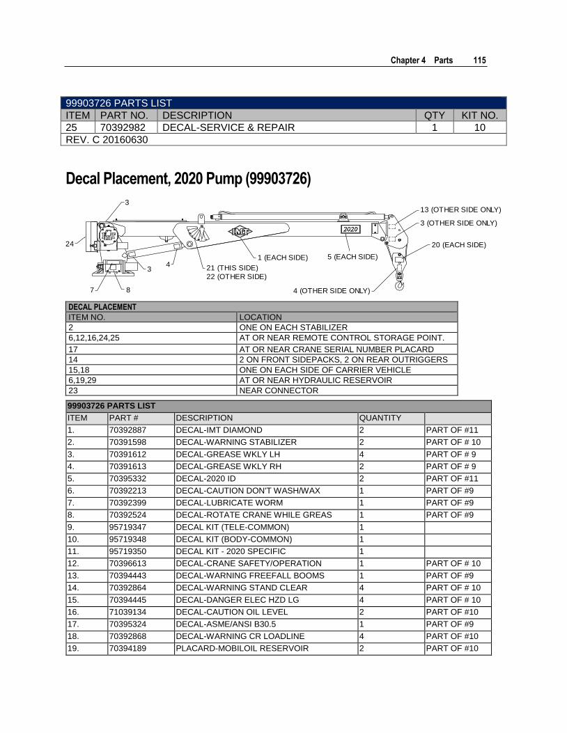
Chapter 4 Parts 115
99903726 PARTS LIST
ITEM PART NO. DESCRIPTION QTY KIT NO.
25 70392982 DECAL-SERVICE & REPAIR 1 10
REV. C 20160630
Decal Placement, 2020 Pump (99903726)
3
24
7 8
34
21 (THIS SIDE)
22 (OTHER SIDE)
1 (EACH SIDE) 5 (EACH SIDE)
13 (OTHER SIDE ONLY)
3 (OTHER SIDE ONLY)
20 (EACH SIDE)
4 (OTHER SIDE ONLY)
DECAL PLACEMENT
ITEM NO. LOCATION
2 ONE ON EACH STABILIZER
6,12,16,24,25 AT OR NEAR REMOTE CONTROL STORAGE POINT.
17 AT OR NEAR CRANE SERIAL NUMBER PLACARD
14 2 ON FRONT SIDEPACKS, 2 ON REAR OUTRIGGERS
15,18 ONE ON EACH SIDE OF CARRIER VEHICLE
6,19,29 AT OR NEAR HYDRAULIC RESERVOIR
23 NEAR CONNECTOR
99903726 PARTS LIST
ITEM PART # DESCRIPTION QUANTITY
1. 70392887 DECAL-IMT DIAMOND 2 PART OF #11
2. 70391598 DECAL-WARNING STABILIZER 2 PART OF # 10
3. 70391612 DECAL-GREASE WKLY LH 4 PART OF # 9
4. 70391613 DECAL-GREASE WKLY RH 2 PART OF # 9
5. 70395332 DECAL-2020 ID 2 PART OF #11
6. 70392213 DECAL-CAUTION DON'T WASH/WAX 1 PART OF #9
7. 70392399 DECAL-LUBRICATE WORM 1 PART OF #9
8. 70392524 DECAL-ROTATE CRANE WHILE GREAS 1 PART OF #9
9. 95719347 DECAL KIT (TELE-COMMON) 1
10. 95719348 DECAL KIT (BODY-COMMON) 1
11. 95719350 DECAL KIT - 2020 SPECIFIC 1
12. 70396613 DECAL-CRANE SAFETY/OPERATION 1 PART OF # 10
13. 70394443 DECAL-WARNING FREEFALL BOOMS 1 PART OF #9
14. 70392864 DECAL-WARNING STAND CLEAR 4 PART OF # 10
15. 70394445 DECAL-DANGER ELEC HZD LG 4 PART OF # 10
16. 71039134 DECAL-CAUTION OIL LEVEL 2 PART OF #10
17. 70395324 DECAL-ASME/ANSI B30.5 1 PART OF #9
18. 70392868 DECAL-WARNING CR LOADLINE 4 PART OF #10
19. 70394189 PLACARD-MOBILOIL RESERVOIR 2 PART OF #10
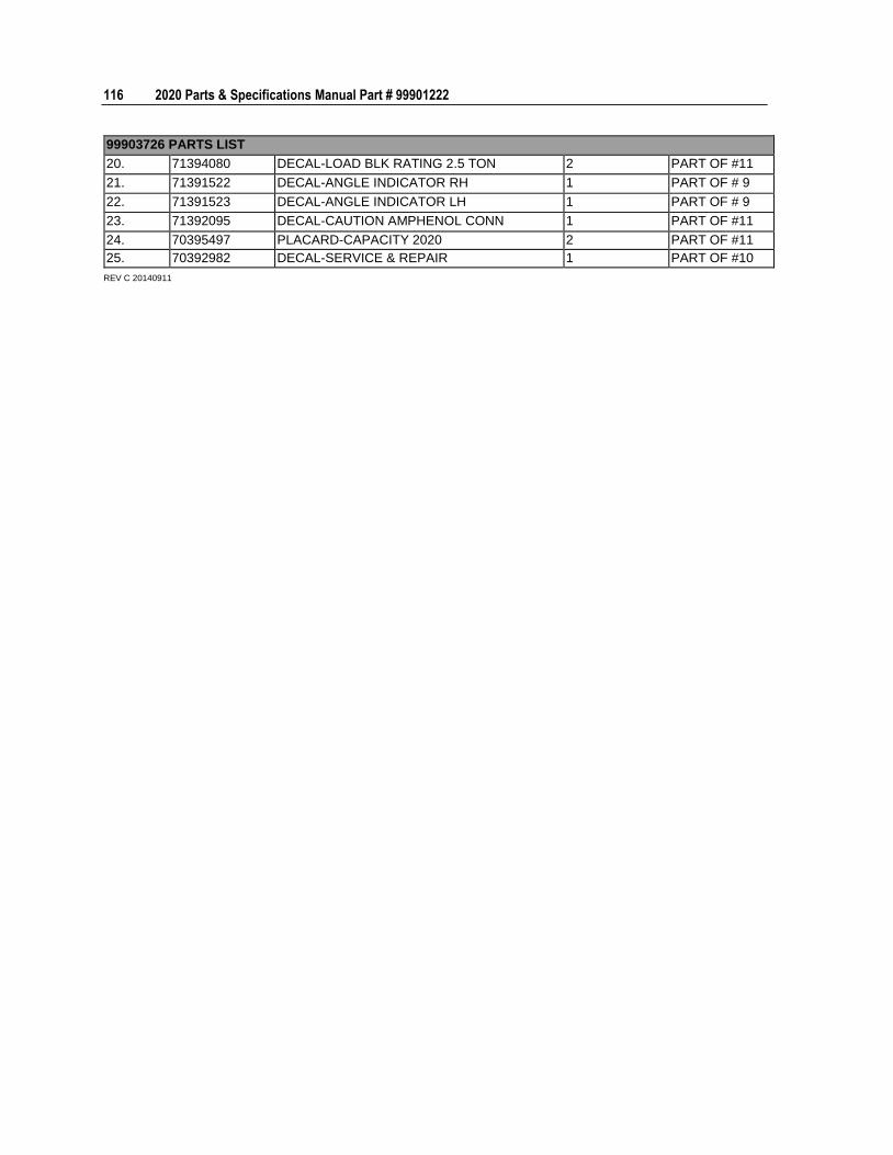
116 2020 Parts & Specifications Manual Part # 99901222
99903726 PARTS LIST
20. 71394080 DECAL-LOAD BLK RATING 2.5 TON 2 PART OF #11
21. 71391522 DECAL-ANGLE INDICATOR RH 1 PART OF # 9
22. 71391523 DECAL-ANGLE INDICATOR LH 1 PART OF # 9
23. 71392095 DECAL-CAUTION AMPHENOL CONN 1 PART OF #11
24. 70395497 PLACARD-CAPACITY 2020 2 PART OF #11
25. 70392982 DECAL-SERVICE & REPAIR 1 PART OF #10
REV C 20140911
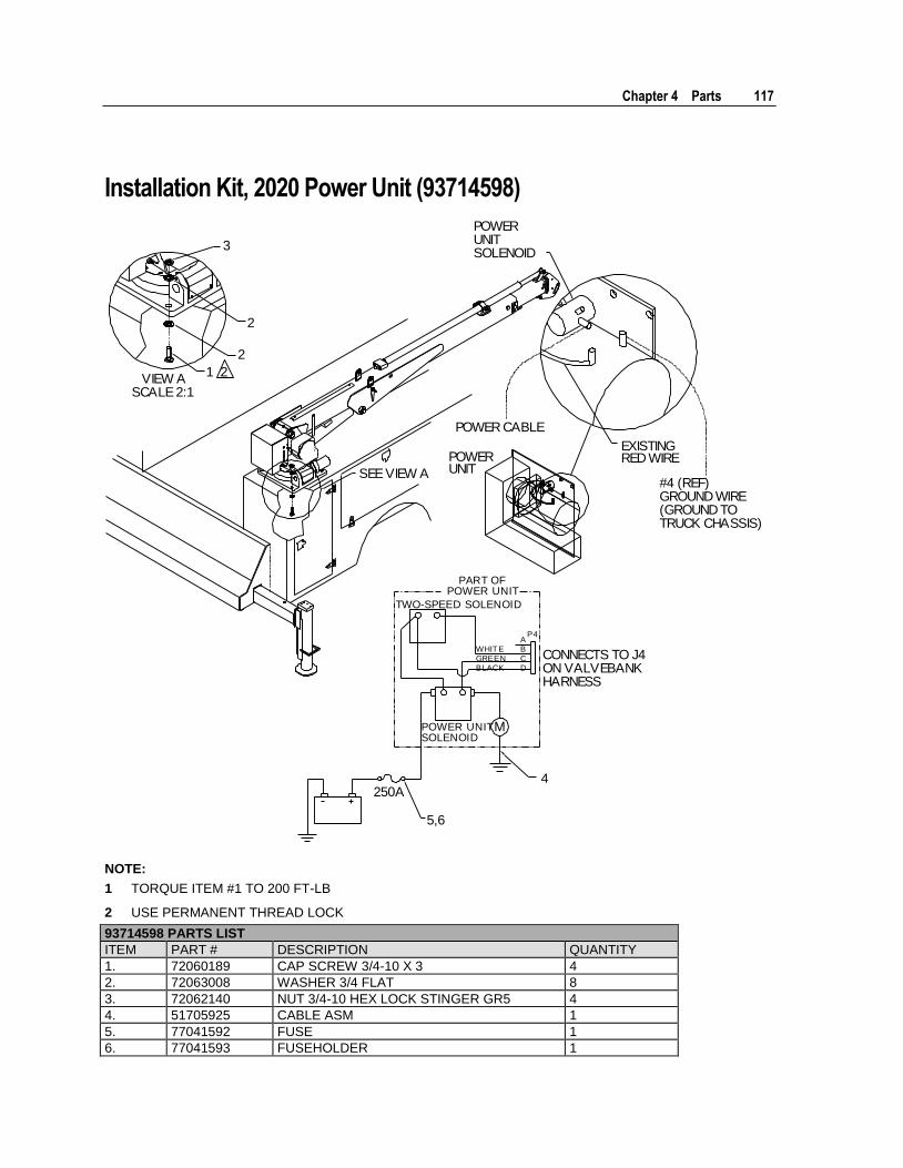
Chapter 4 Parts 117
Installation Kit, 2020 Power Unit (93714598)
CONNECTS TO J4ON VALVEBANKHARNESS
POWER UNITSOLENOID
TWO-SPEED SOLENOID
PART OFPOWER UNIT
4
AWHIT E BGREEN CBLACK D
P4
250A
M
5,6
SEE VIEW A
POWERUNIT
POWER CABLE
EXISTINGRED WIRE
#4 (REF)GROUND WIRE(GROUND TOTRUCK CHASSIS)
VIEW ASCALE 2:1
POWERUNITSOLENOID
1 2
2
2
3
NOTE:
1 TORQUE ITEM #1 TO 200 FT-LB
2 USE PERMANENT THREAD LOCK
93714598 PARTS LIST
ITEM PART # DESCRIPTION QUANTITY
1. 72060189 CAP SCREW 3/4-10 X 3 4
2. 72063008 WASHER 3/4 FLAT 8
3. 72062140 NUT 3/4-10 HEX LOCK STINGER GR5 4
4. 51705925 CABLE ASM 1
5. 77041592 FUSE 1
6. 77041593 FUSEHOLDER 1

118 2020 Parts & Specifications Manual Part # 99901222
93714598 PARTS LIST
ITEM PART # DESCRIPTION QUANTITY
REV. B
20050913
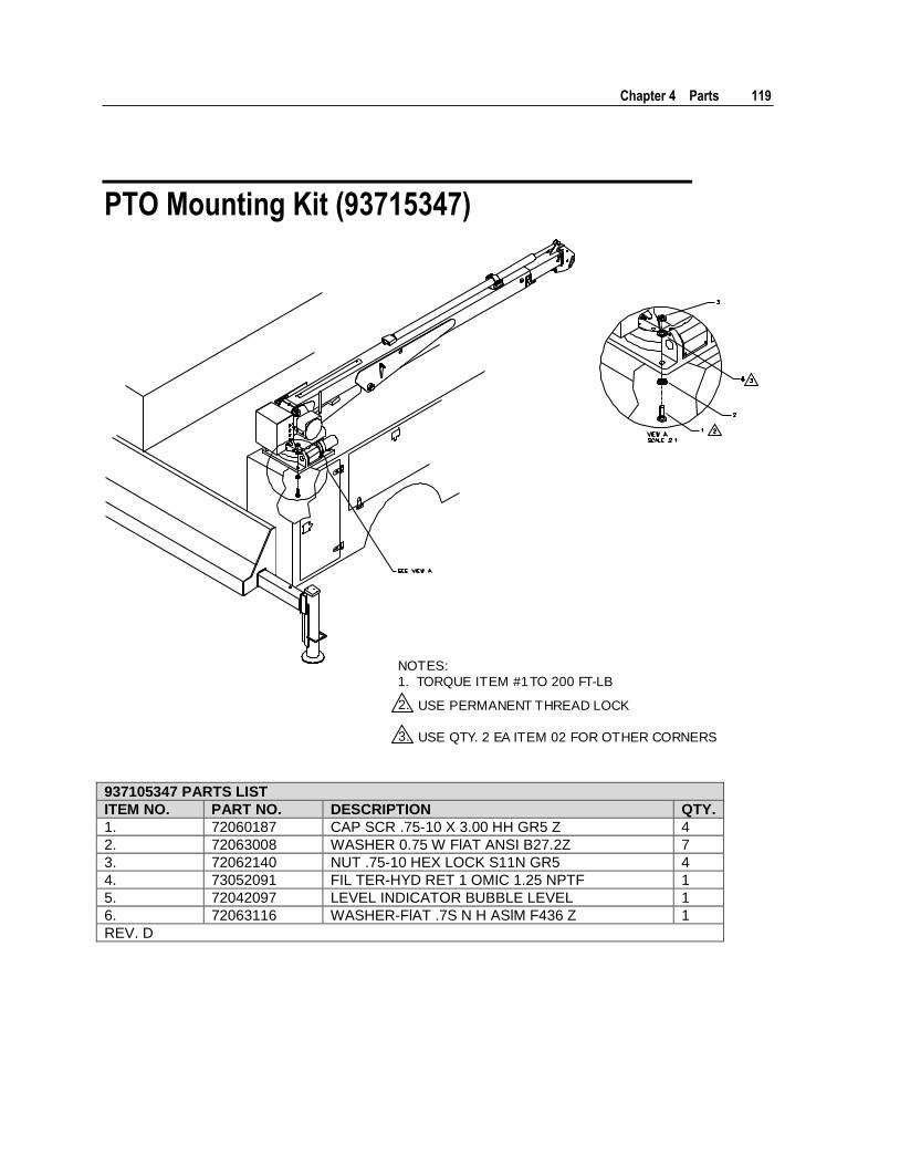
Chapter 4 Parts 119
PTO Mounting Kit (93715347)
2.
3.
NOTES:
1. TORQUE ITEM #1 TO 200 FT-LB
USE PERMANENT THREAD LOCK
USE QTY. 2 EA ITEM 02 FOR OTHER CORNERS
937105347 PARTS LIST
ITEM NO. PART NO. DESCRIPTION QTY.
1. 72060187 CAP SCR .75-10 X 3.00 HH GR5 Z 4
2. 72063008 WASHER 0.75 W FlAT ANSI B27.2Z 7
3. 72062140 NUT .75-10 HEX LOCK S11N GR5 4
4. 73052091 FIL TER-HYD RET 1 OMIC 1.25 NPTF 1
5. 72042097 LEVEL INDICATOR BUBBLE LEVEL 1
6. 72063116 WASHER-FlAT .7S N H ASlM F436 Z 1
REV. D
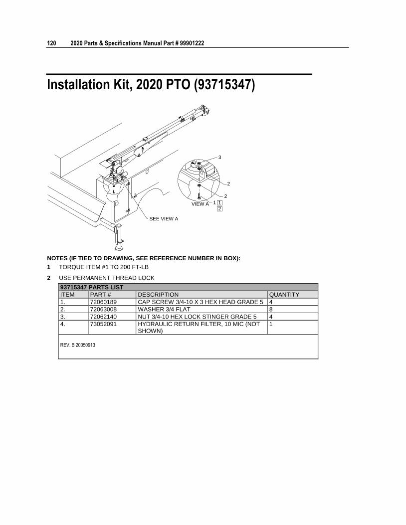
120 2020 Parts & Specifications Manual Part # 99901222
Installation Kit, 2020 PTO (93715347)
SEE VIEW A
VIEW A 1
2
2
3
2
1
NOTES (IF TIED TO DRAWING, SEE REFERENCE NUMBER IN BOX):
1 TORQUE ITEM #1 TO 200 FT-LB
2 USE PERMANENT THREAD LOCK
93715347 PARTS LIST
ITEM PART # DESCRIPTION QUANTITY
1. 72060189 CAP SCREW 3/4-10 X 3 HEX HEAD GRADE 5 4
2. 72063008 WASHER 3/4 FLAT 8
3. 72062140 NUT 3/4-10 HEX LOCK STINGER GRADE 5 4
4. 73052091 HYDRAULIC RETURN FILTER, 10 MIC (NOT SHOWN)
1
REV. B 20050913
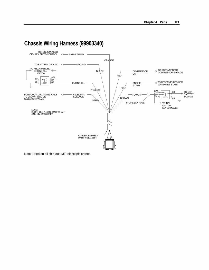
Chapter 4 Parts 121
Chassis Wiring Harness (99903340)
TO 12VBATTERYSOURCE
TO 12VIGNITIONKEYED POWER
IN-LINE 10A FUSE
POWER
ENGINESTART
COMPRESSORON
TO RECOMMENDED OEM12V ENGINE START
TO RECOMMENDEDCOMPRESSOR ENGAGE
87A8786
30
85
ENGINE SPEED
GROUND
ENGINE KILL
SELECTORSOLENOID
CABLE ASSEMBLYPART # 51715664
NOTE:BLUNT CUT AND SHRINK WRAPANY UNUSED WIRES.
FOR FORD AUTO TRANS. ONLYTO BROWN WIRE ONSELECTOR VALVE
30
85
87A8786
TO RECOMMENDEDENGINE KILL
OPTION
TO BATTERY GROUND
TO RECOMMENDEDOEM 12V SPEED CONTROL
RED
BLUE
BROWN
BLACK
ORANGE
YELLOW
GREEN
Note: Used on all ship-out IMT telescopic cranes.

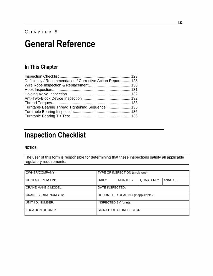
123
In This Chapter
Inspection Checklist ................................................................. 123 Deficiency / Recommendation / Corrective Action Report ......... 128 Wire Rope Inspection & Replacement ...................................... 130 Hook Inspection........................................................................ 131 Holding Valve Inspection .......................................................... 132 Anti-Two-Block Device Inspection ............................................ 132 Thread Torques ........................................................................ 133 Turntable Bearing Thread Tightening Sequence ...................... 135 Turntable Bearing Inspection .................................................... 136 Turntable Bearing Tilt Test ....................................................... 136
Inspection Checklist
NOTICE:
The user of this form is responsible for determining that these inspections satisfy all applicable regulatory requirements.
OWNER/COMPANY:
TYPE OF INSPECTION (circle one):
CONTACT PERSON: DAILY MONTHLY QUARTERLY ANNUAL
CRANE MAKE & MODEL: DATE INSPECTED:
CRANE SERIAL NUMBER: HOURMETER READING (if applicable):
UNIT I.D. NUMBER:
INSPECTED BY (print):
LOCATION OF UNIT: SIGNATURE OF INSPECTOR:
C H A P T E R 5
General Reference
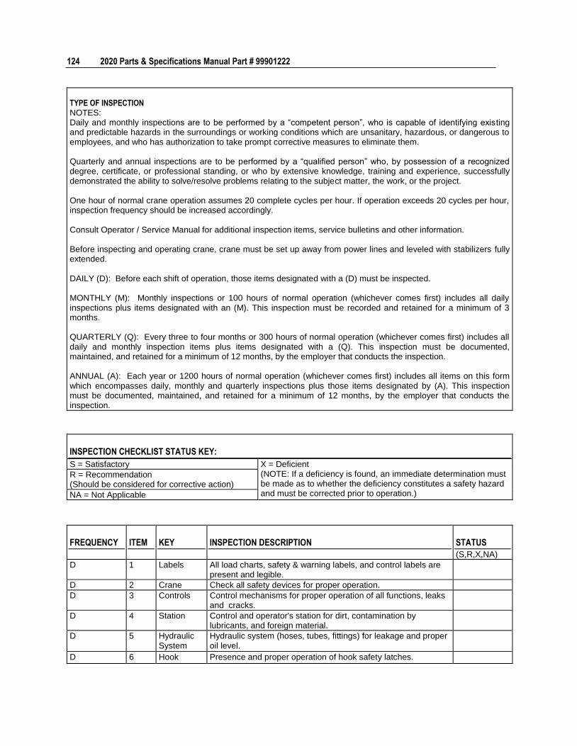
124 2020 Parts & Specifications Manual Part # 99901222
TYPE OF INSPECTION NOTES: Daily and monthly inspections are to be performed by a “competent person”, who is capable of identifying existing and predictable hazards in the surroundings or working conditions which are unsanitary, hazardous, or dangerous to employees, and who has authorization to take prompt corrective measures to eliminate them. Quarterly and annual inspections are to be performed by a “qualified person” who, by possession of a recognized degree, certificate, or professional standing, or who by extensive knowledge, training and experience, successfully demonstrated the ability to solve/resolve problems relating to the subject matter, the work, or the project. One hour of normal crane operation assumes 20 complete cycles per hour. If operation exceeds 20 cycles per hour, inspection frequency should be increased accordingly. Consult Operator / Service Manual for additional inspection items, service bulletins and other information. Before inspecting and operating crane, crane must be set up away from power lines and leveled with stabilizers fully extended. DAILY (D): Before each shift of operation, those items designated with a (D) must be inspected. MONTHLY (M): Monthly inspections or 100 hours of normal operation (whichever comes first) includes all daily inspections plus items designated with an (M). This inspection must be recorded and retained for a minimum of 3 months. QUARTERLY (Q): Every three to four months or 300 hours of normal operation (whichever comes first) includes all daily and monthly inspection items plus items designated with a (Q). This inspection must be documented, maintained, and retained for a minimum of 12 months, by the employer that conducts the inspection. ANNUAL (A): Each year or 1200 hours of normal operation (whichever comes first) includes all items on this form which encompasses daily, monthly and quarterly inspections plus those items designated by (A). This inspection must be documented, maintained, and retained for a minimum of 12 months, by the employer that conducts the inspection.
INSPECTION CHECKLIST STATUS KEY:
S = Satisfactory X = Deficient (NOTE: If a deficiency is found, an immediate determination must be made as to whether the deficiency constitutes a safety hazard and must be corrected prior to operation.)
R = Recommendation (Should be considered for corrective action)
NA = Not Applicable
FREQUENCY ITEM KEY INSPECTION DESCRIPTION STATUS
(S,R,X,NA)
D 1 Labels All load charts, safety & warning labels, and control labels are present and legible.
D 2 Crane Check all safety devices for proper operation.
D 3 Controls Control mechanisms for proper operation of all functions, leaks and cracks.
D 4 Station Control and operator's station for dirt, contamination by lubricants, and foreign material.
D 5 Hydraulic System
Hydraulic system (hoses, tubes, fittings) for leakage and proper oil level.
D 6 Hook Presence and proper operation of hook safety latches.
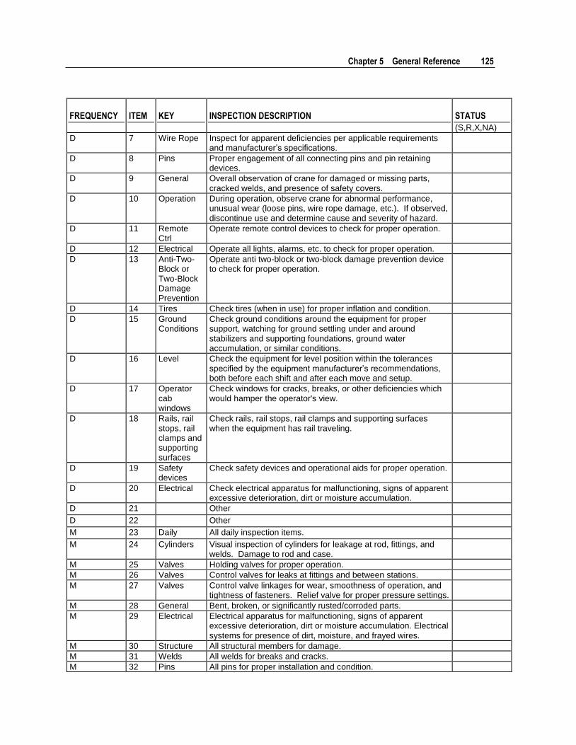
Chapter 5 General Reference 125
FREQUENCY ITEM KEY INSPECTION DESCRIPTION STATUS
(S,R,X,NA)
D 7 Wire Rope Inspect for apparent deficiencies per applicable requirements and manufacturer’s specifications.
D 8 Pins Proper engagement of all connecting pins and pin retaining devices.
D 9 General Overall observation of crane for damaged or missing parts, cracked welds, and presence of safety covers.
D 10 Operation During operation, observe crane for abnormal performance, unusual wear (loose pins, wire rope damage, etc.). If observed, discontinue use and determine cause and severity of hazard.
D 11 Remote Ctrl
Operate remote control devices to check for proper operation.
D 12 Electrical Operate all lights, alarms, etc. to check for proper operation.
D 13 Anti-Two-Block or Two-Block Damage Prevention
Operate anti two-block or two-block damage prevention device to check for proper operation.
D 14 Tires Check tires (when in use) for proper inflation and condition.
D 15 Ground Conditions
Check ground conditions around the equipment for proper support, watching for ground settling under and around stabilizers and supporting foundations, ground water accumulation, or similar conditions.
D 16 Level Check the equipment for level position within the tolerances specified by the equipment manufacturer’s recommendations, both before each shift and after each move and setup.
D 17 Operator cab windows
Check windows for cracks, breaks, or other deficiencies which would hamper the operator's view.
D 18 Rails, rail stops, rail clamps and supporting surfaces
Check rails, rail stops, rail clamps and supporting surfaces when the equipment has rail traveling.
D 19 Safety devices
Check safety devices and operational aids for proper operation.
D 20 Electrical Check electrical apparatus for malfunctioning, signs of apparent excessive deterioration, dirt or moisture accumulation.
D 21 Other
D 22 Other
M 23 Daily All daily inspection items.
M 24 Cylinders Visual inspection of cylinders for leakage at rod, fittings, and welds. Damage to rod and case.
M 25 Valves Holding valves for proper operation.
M 26 Valves Control valves for leaks at fittings and between stations.
M 27 Valves Control valve linkages for wear, smoothness of operation, and tightness of fasteners. Relief valve for proper pressure settings.
M 28 General Bent, broken, or significantly rusted/corroded parts.
M 29 Electrical Electrical apparatus for malfunctioning, signs of apparent excessive deterioration, dirt or moisture accumulation. Electrical systems for presence of dirt, moisture, and frayed wires.
M 30 Structure All structural members for damage.
M 31 Welds All welds for breaks and cracks.
M 32 Pins All pins for proper installation and condition.
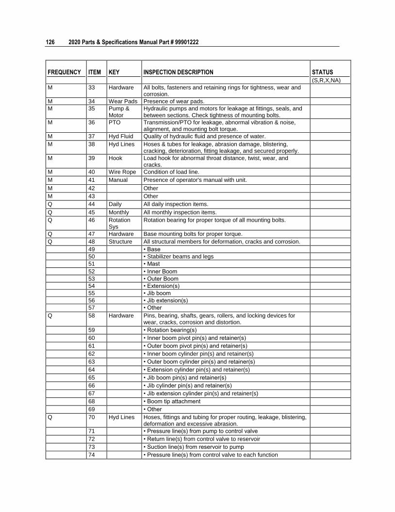
126 2020 Parts & Specifications Manual Part # 99901222
FREQUENCY ITEM KEY INSPECTION DESCRIPTION STATUS
(S,R,X,NA)
M 33 Hardware All bolts, fasteners and retaining rings for tightness, wear and corrosion.
M 34 Wear Pads Presence of wear pads.
M 35 Pump & Motor
Hydraulic pumps and motors for leakage at fittings, seals, and between sections. Check tightness of mounting bolts.
M 36 PTO Transmission/PTO for leakage, abnormal vibration & noise, alignment, and mounting bolt torque.
M 37 Hyd Fluid Quality of hydraulic fluid and presence of water.
M 38 Hyd Lines Hoses & tubes for leakage, abrasion damage, blistering, cracking, deterioration, fitting leakage, and secured properly.
M 39 Hook Load hook for abnormal throat distance, twist, wear, and cracks.
M 40 Wire Rope Condition of load line.
M 41 Manual Presence of operator's manual with unit.
M 42 Other
M 43 Other
Q 44 Daily All daily inspection items.
Q 45 Monthly All monthly inspection items.
Q 46 Rotation Sys
Rotation bearing for proper torque of all mounting bolts.
Q 47 Hardware Base mounting bolts for proper torque.
Q 48 Structure All structural members for deformation, cracks and corrosion.
49 • Base
50 • Stabilizer beams and legs
51 • Mast
52 • Inner Boom
53 • Outer Boom
54 • Extension(s)
55 • Jib boom
56 • Jib extension(s)
57 • Other
Q 58 Hardware Pins, bearing, shafts, gears, rollers, and locking devices for wear, cracks, corrosion and distortion.
59 • Rotation bearing(s)
60 • Inner boom pivot pin(s) and retainer(s)
61 • Outer boom pivot pin(s) and retainer(s)
62 • Inner boom cylinder pin(s) and retainer(s)
63 • Outer boom cylinder pin(s) and retainer(s)
64 • Extension cylinder pin(s) and retainer(s)
65 • Jib boom pin(s) and retainer(s)
66 • Jib cylinder pin(s) and retainer(s)
67 • Jib extension cylinder pin(s) and retainer(s)
68 • Boom tip attachment
69 • Other
Q 70 Hyd Lines Hoses, fittings and tubing for proper routing, leakage, blistering, deformation and excessive abrasion.
71 • Pressure line(s) from pump to control valve
72 • Return line(s) from control valve to reservoir
73 • Suction line(s) from reservoir to pump
74 • Pressure line(s) from control valve to each function
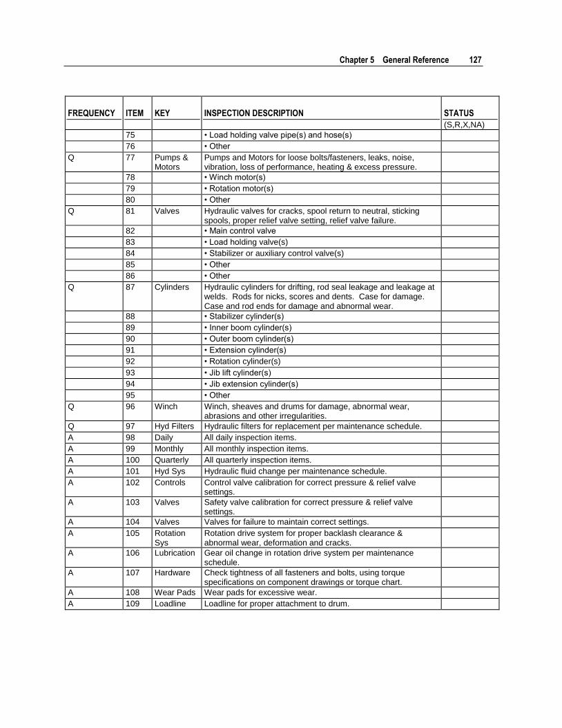
Chapter 5 General Reference 127
FREQUENCY ITEM KEY INSPECTION DESCRIPTION STATUS
(S,R,X,NA)
75 • Load holding valve pipe(s) and hose(s)
76 • Other
Q 77 Pumps & Motors
Pumps and Motors for loose bolts/fasteners, leaks, noise, vibration, loss of performance, heating & excess pressure.
78 • Winch motor(s)
79 • Rotation motor(s)
80 • Other
Q 81 Valves Hydraulic valves for cracks, spool return to neutral, sticking spools, proper relief valve setting, relief valve failure.
82 • Main control valve
83 • Load holding valve(s)
84 • Stabilizer or auxiliary control valve(s)
85 • Other
86 • Other
Q 87 Cylinders Hydraulic cylinders for drifting, rod seal leakage and leakage at welds. Rods for nicks, scores and dents. Case for damage. Case and rod ends for damage and abnormal wear.
88 • Stabilizer cylinder(s)
89 • Inner boom cylinder(s)
90 • Outer boom cylinder(s)
91 • Extension cylinder(s)
92 • Rotation cylinder(s)
93 • Jib lift cylinder(s)
94 • Jib extension cylinder(s)
95 • Other
Q 96 Winch Winch, sheaves and drums for damage, abnormal wear, abrasions and other irregularities.
Q 97 Hyd Filters Hydraulic filters for replacement per maintenance schedule.
A 98 Daily All daily inspection items.
A 99 Monthly All monthly inspection items.
A 100 Quarterly All quarterly inspection items.
A 101 Hyd Sys Hydraulic fluid change per maintenance schedule.
A 102 Controls Control valve calibration for correct pressure & relief valve settings.
A 103 Valves Safety valve calibration for correct pressure & relief valve settings.
A 104 Valves Valves for failure to maintain correct settings.
A 105 Rotation Sys
Rotation drive system for proper backlash clearance & abnormal wear, deformation and cracks.
A 106 Lubrication Gear oil change in rotation drive system per maintenance schedule.
A 107 Hardware Check tightness of all fasteners and bolts, using torque specifications on component drawings or torque chart.
A 108 Wear Pads Wear pads for excessive wear.
A 109 Loadline Loadline for proper attachment to drum.
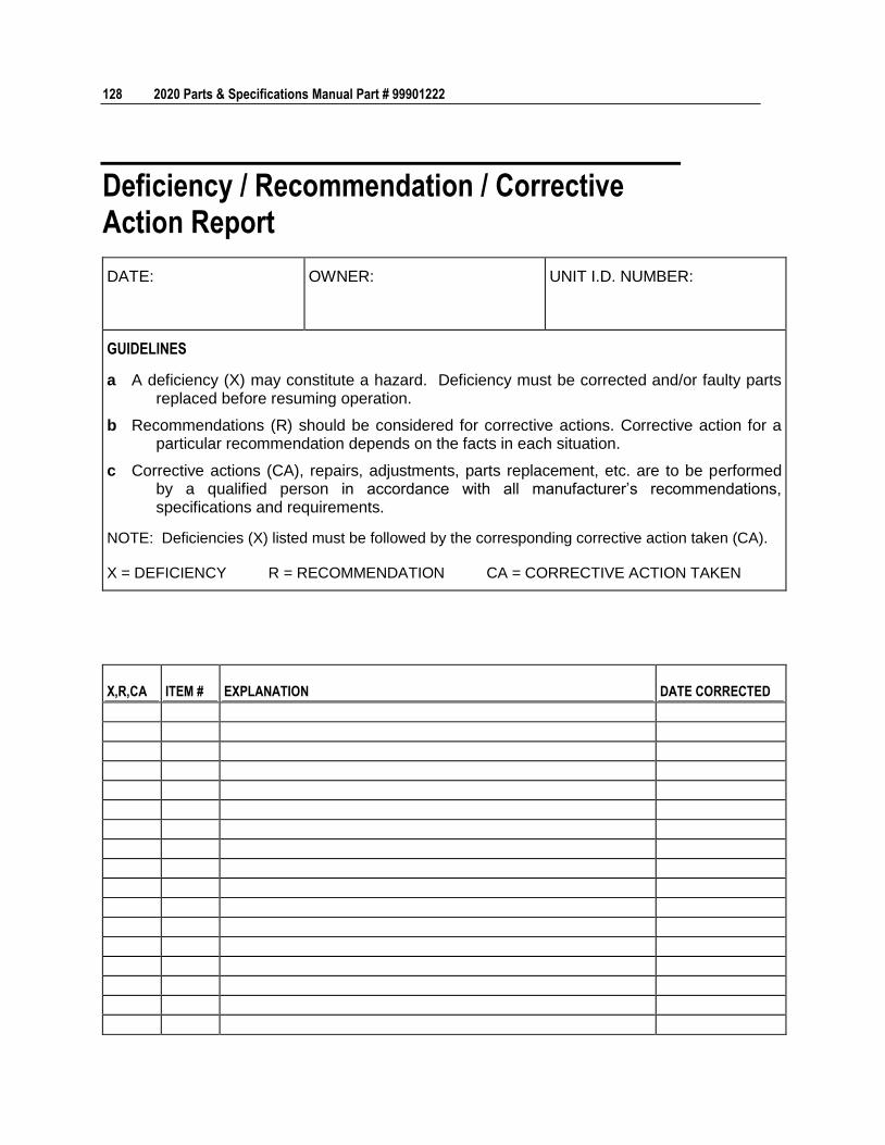
128 2020 Parts & Specifications Manual Part # 99901222
Deficiency / Recommendation / Corrective Action Report
DATE: OWNER: UNIT I.D. NUMBER:
GUIDELINES
a A deficiency (X) may constitute a hazard. Deficiency must be corrected and/or faulty parts replaced before resuming operation.
b Recommendations (R) should be considered for corrective actions. Corrective action for a particular recommendation depends on the facts in each situation.
c Corrective actions (CA), repairs, adjustments, parts replacement, etc. are to be performed by a qualified person in accordance with all manufacturer’s recommendations, specifications and requirements.
NOTE: Deficiencies (X) listed must be followed by the corresponding corrective action taken (CA).
X = DEFICIENCY R = RECOMMENDATION CA = CORRECTIVE ACTION TAKEN
X,R,CA ITEM # EXPLANATION DATE CORRECTED

Chapter 5 General Reference 129
X,R,CA ITEM # EXPLANATION DATE CORRECTED
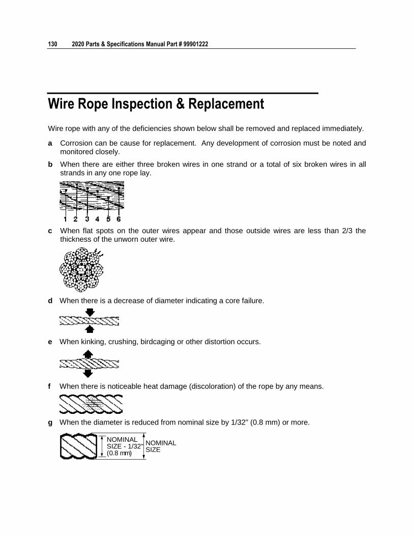
130 2020 Parts & Specifications Manual Part # 99901222
Wire Rope Inspection & Replacement
Wire rope with any of the deficiencies shown below shall be removed and replaced immediately.
a Corrosion can be cause for replacement. Any development of corrosion must be noted and monitored closely.
b When there are either three broken wires in one strand or a total of six broken wires in all strands in any one rope lay.
c When flat spots on the outer wires appear and those outside wires are less than 2/3 the thickness of the unworn outer wire.
d When there is a decrease of diameter indicating a core failure.
e When kinking, crushing, birdcaging or other distortion occurs.
f When there is noticeable heat damage (discoloration) of the rope by any means.
g When the diameter is reduced from nominal size by 1/32" (0.8 mm) or more.
NOMINALSIZE - 1/32"(0.8 mm)
NOMINALSIZE
Chapter 5 General Reference 131
h If a broken wire protrudes or loops out from the core of the rope.
Hook Inspection
Hooks having any of the listed deficiencies shall be removed from service unless a qualified person approves their continued use and initiates corrective action. Hooks approved for continued use shall be subjected to periodic inspection.
a DISTORTION
Bending / Twisting
A bend or twist exceeding 10° from the plane of the unbent hook.
Increased Throat Opening
HOOK WITHOUT LATCH: An increase in throat opening exceeding 15% (Or as recommended by the manufacturer).
HOOK WITH LATCH: An increase of the dimension between a fully-opened latch and the tip section of the hook exceeding 8% (Or as recommended by the manufacturer).
b WEAR
If wear exceeds 10% of the original sectional dimension. (Or as recommended by the manufacturer).
c CRACKS, NICKS, GOUGES
Repair of cracks, nicks, and gouges shall be carried out by a designated person by grinding longitudinally, following the contour of the hook, provided that no dimension is reduced more than 10% of its original value. (Or as recommended by the manufacturer). (A qualified person may authorize continued use if the reduced area is not critical).
d LATCH
Engagement, Damage & Malfunction
If a latch becomes inoperative because of wear or deformation, and is required for the service involved, it shall be replaced or repaired before the hook is put back into service. If the latch fails to fully close the throat opening, the hook shall be removed from service or wired closed (moused) until repairs are made.
e HOOK ATTACHMENTS & SECURING MEANS
If any indication of distortion, wear, cracks, nicks or gouges are present, unless a qualified person authorizes their use. (Or as recommended by the manufacturer).
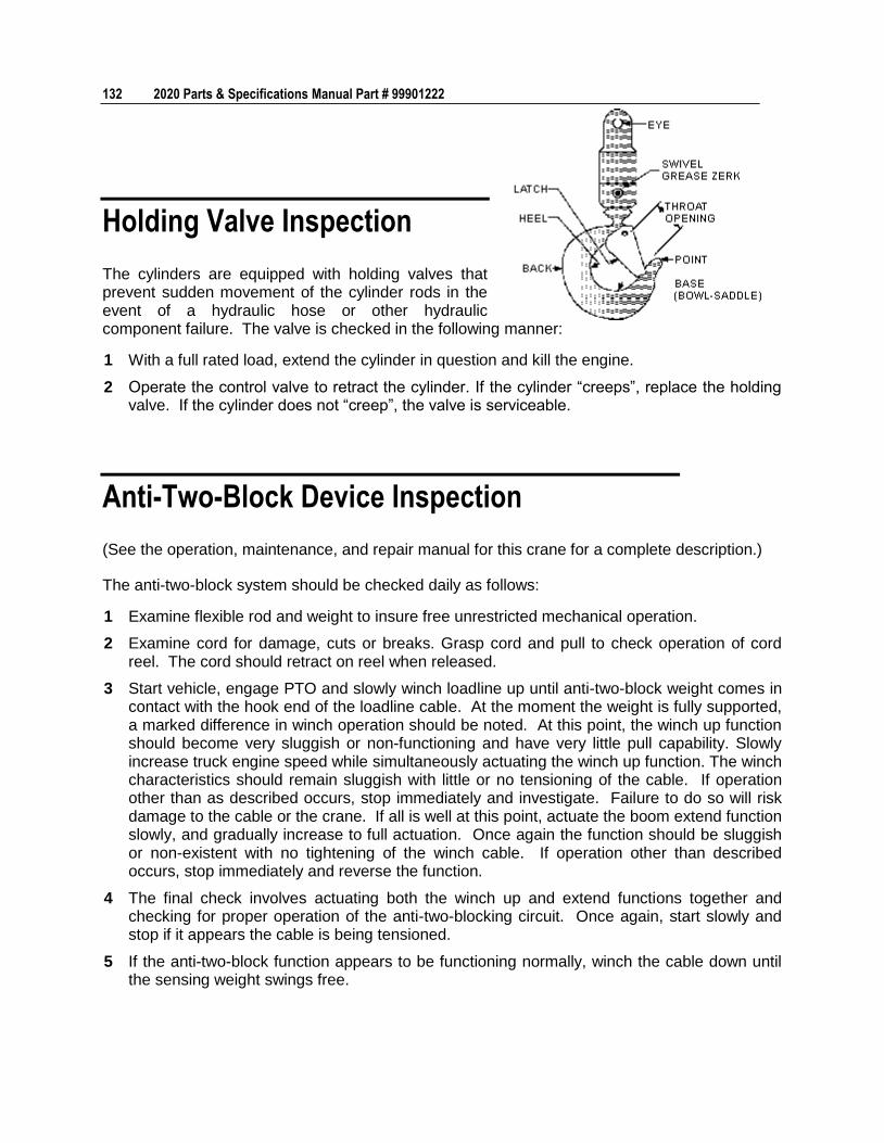
132 2020 Parts & Specifications Manual Part # 99901222
Holding Valve Inspection
The cylinders are equipped with holding valves that prevent sudden movement of the cylinder rods in the event of a hydraulic hose or other hydraulic component failure. The valve is checked in the following manner:
1 With a full rated load, extend the cylinder in question and kill the engine.
2 Operate the control valve to retract the cylinder. If the cylinder “creeps”, replace the holding valve. If the cylinder does not “creep”, the valve is serviceable.
Anti-Two-Block Device Inspection
(See the operation, maintenance, and repair manual for this crane for a complete description.)
The anti-two-block system should be checked daily as follows:
1 Examine flexible rod and weight to insure free unrestricted mechanical operation.
2 Examine cord for damage, cuts or breaks. Grasp cord and pull to check operation of cord reel. The cord should retract on reel when released.
3 Start vehicle, engage PTO and slowly winch loadline up until anti-two-block weight comes in contact with the hook end of the loadline cable. At the moment the weight is fully supported, a marked difference in winch operation should be noted. At this point, the winch up function should become very sluggish or non-functioning and have very little pull capability. Slowly increase truck engine speed while simultaneously actuating the winch up function. The winch characteristics should remain sluggish with little or no tensioning of the cable. If operation other than as described occurs, stop immediately and investigate. Failure to do so will risk damage to the cable or the crane. If all is well at this point, actuate the boom extend function slowly, and gradually increase to full actuation. Once again the function should be sluggish or non-existent with no tightening of the winch cable. If operation other than described occurs, stop immediately and reverse the function.
4 The final check involves actuating both the winch up and extend functions together and checking for proper operation of the anti-two-blocking circuit. Once again, start slowly and stop if it appears the cable is being tensioned.
5 If the anti-two-block function appears to be functioning normally, winch the cable down until the sensing weight swings free.
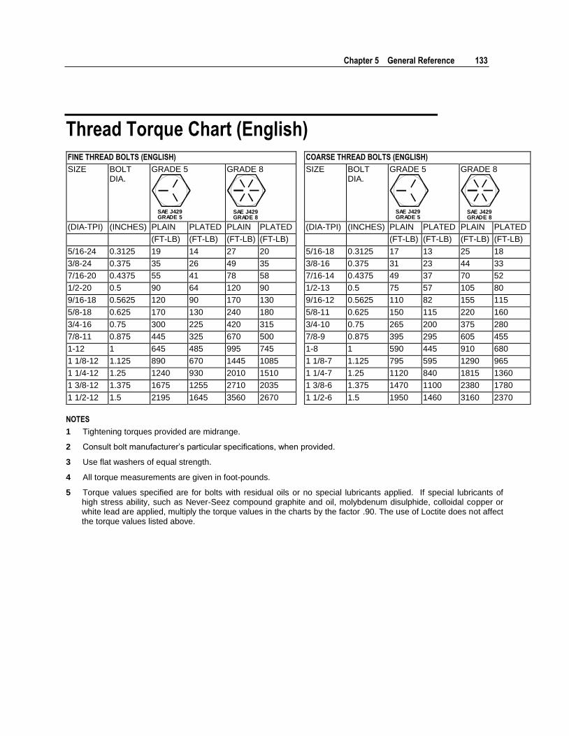
Chapter 5 General Reference 133
Thread Torque Chart (English)
FINE THREAD BOLTS (ENGLISH) COARSE THREAD BOLTS (ENGLISH)
SIZE BOLT DIA.
GRADE 5
SAE J429GRADE 5
GRADE 8
SAE J429GRADE 8
SIZE BOLT DIA.
GRADE 5
SAE J429GRADE 5
GRADE 8
SAE J429GRADE 8
(DIA-TPI) (INCHES) PLAIN PLATED PLAIN PLATED (DIA-TPI) (INCHES) PLAIN PLATED PLAIN PLATED
(FT-LB) (FT-LB) (FT-LB) (FT-LB) (FT-LB) (FT-LB) (FT-LB) (FT-LB)
5/16-24 0.3125 19 14 27 20 5/16-18 0.3125 17 13 25 18
3/8-24 0.375 35 26 49 35 3/8-16 0.375 31 23 44 33
7/16-20 0.4375 55 41 78 58 7/16-14 0.4375 49 37 70 52
1/2-20 0.5 90 64 120 90 1/2-13 0.5 75 57 105 80
9/16-18 0.5625 120 90 170 130 9/16-12 0.5625 110 82 155 115
5/8-18 0.625 170 130 240 180 5/8-11 0.625 150 115 220 160
3/4-16 0.75 300 225 420 315 3/4-10 0.75 265 200 375 280
7/8-11 0.875 445 325 670 500 7/8-9 0.875 395 295 605 455
1-12 1 645 485 995 745 1-8 1 590 445 910 680
1 1/8-12 1.125 890 670 1445 1085 1 1/8-7 1.125 795 595 1290 965
1 1/4-12 1.25 1240 930 2010 1510 1 1/4-7 1.25 1120 840 1815 1360
1 3/8-12 1.375 1675 1255 2710 2035 1 3/8-6 1.375 1470 1100 2380 1780
1 1/2-12 1.5 2195 1645 3560 2670 1 1/2-6 1.5 1950 1460 3160 2370
NOTES
1 Tightening torques provided are midrange.
2 Consult bolt manufacturer’s particular specifications, when provided.
3 Use flat washers of equal strength.
4 All torque measurements are given in foot-pounds.
5 Torque values specified are for bolts with residual oils or no special lubricants applied. If special lubricants of high stress ability, such as Never-Seez compound graphite and oil, molybdenum disulphide, colloidal copper or white lead are applied, multiply the torque values in the charts by the factor .90. The use of Loctite does not affect the torque values listed above.
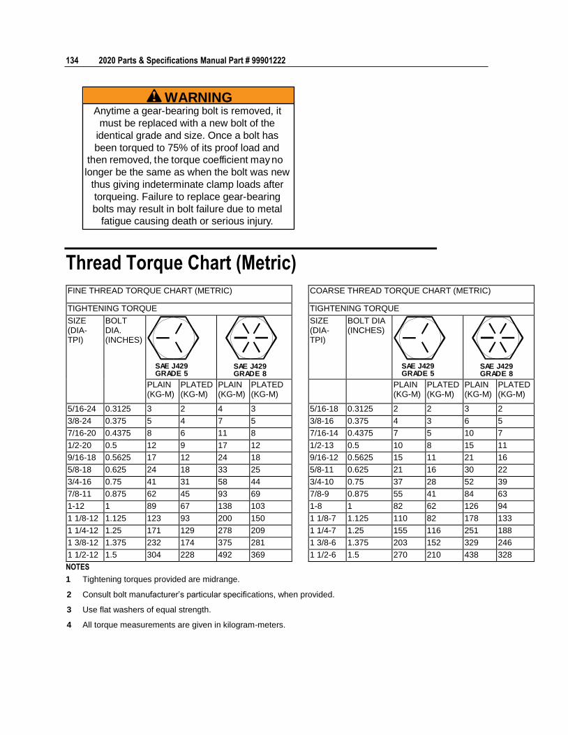
134 2020 Parts & Specifications Manual Part # 99901222
WARNINGAnytime a gear-bearing bolt is removed, it
must be replaced with a new bolt of the
identical grade and size. Once a bolt has
been torqued to 75% of its proof load and
then removed, the torque coefficient may no
longer be the same as when the bolt was new
thus giving indeterminate clamp loads after
torqueing. Failure to replace gear-bearing
bolts may result in bolt failure due to metal
fatigue causing death or serious injury.
Thread Torque Chart (Metric)
FINE THREAD TORQUE CHART (METRIC) COARSE THREAD TORQUE CHART (METRIC)
TIGHTENING TORQUE TIGHTENING TORQUE
SIZE (DIA-TPI)
BOLT DIA. (INCHES)
SAE J429GRADE 5
SAE J429GRADE 8
SIZE (DIA-TPI)
BOLT DIA (INCHES)
SAE J429GRADE 5
SAE J429GRADE 8
PLAIN (KG-M)
PLATED (KG-M)
PLAIN (KG-M)
PLATED (KG-M)
PLAIN (KG-M)
PLATED (KG-M)
PLAIN (KG-M)
PLATED (KG-M)
5/16-24 0.3125 3 2 4 3 5/16-18 0.3125 2 2 3 2
3/8-24 0.375 5 4 7 5 3/8-16 0.375 4 3 6 5
7/16-20 0.4375 8 6 11 8 7/16-14 0.4375 7 5 10 7
1/2-20 0.5 12 9 17 12 1/2-13 0.5 10 8 15 11
9/16-18 0.5625 17 12 24 18 9/16-12 0.5625 15 11 21 16
5/8-18 0.625 24 18 33 25 5/8-11 0.625 21 16 30 22
3/4-16 0.75 41 31 58 44 3/4-10 0.75 37 28 52 39
7/8-11 0.875 62 45 93 69 7/8-9 0.875 55 41 84 63
1-12 1 89 67 138 103 1-8 1 82 62 126 94
1 1/8-12 1.125 123 93 200 150 1 1/8-7 1.125 110 82 178 133
1 1/4-12 1.25 171 129 278 209 1 1/4-7 1.25 155 116 251 188
1 3/8-12 1.375 232 174 375 281 1 3/8-6 1.375 203 152 329 246
1 1/2-12 1.5 304 228 492 369 1 1/2-6 1.5 270 210 438 328
NOTES
1 Tightening torques provided are midrange.
2 Consult bolt manufacturer’s particular specifications, when provided.
3 Use flat washers of equal strength.
4 All torque measurements are given in kilogram-meters.
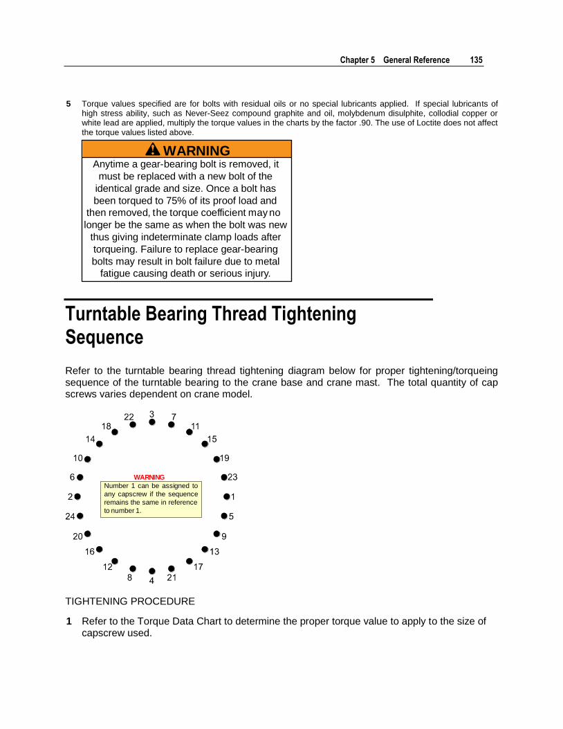
Chapter 5 General Reference 135
5 Torque values specified are for bolts with residual oils or no special lubricants applied. If special lubricants of high stress ability, such as Never-Seez compound graphite and oil, molybdenum disulphite, collodial copper or white lead are applied, multiply the torque values in the charts by the factor .90. The use of Loctite does not affect the torque values listed above.
WARNINGAnytime a gear-bearing bolt is removed, it
must be replaced with a new bolt of the
identical grade and size. Once a bolt has
been torqued to 75% of its proof load and
then removed, the torque coefficient may no
longer be the same as when the bolt was new
thus giving indeterminate clamp loads after
torqueing. Failure to replace gear-bearing
bolts may result in bolt failure due to metal
fatigue causing death or serious injury.
Turntable Bearing Thread Tightening Sequence
Refer to the turntable bearing thread tightening diagram below for proper tightening/torqueing sequence of the turntable bearing to the crane base and crane mast. The total quantity of cap screws varies dependent on crane model.
Number 1 can be assigned to
any capscrew if the sequence
remains the same in reference
to number 1.
WARNING
TIGHTENING PROCEDURE
1 Refer to the Torque Data Chart to determine the proper torque value to apply to the size of capscrew used.
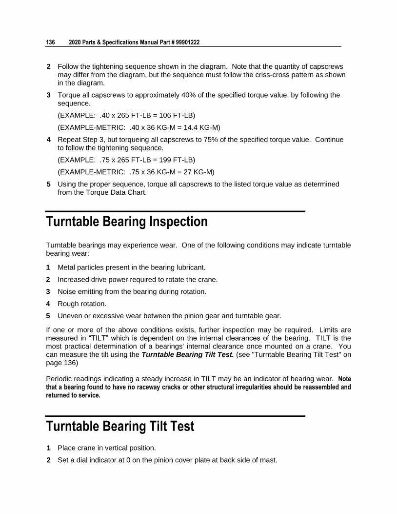
136 2020 Parts & Specifications Manual Part # 99901222
2 Follow the tightening sequence shown in the diagram. Note that the quantity of capscrews may differ from the diagram, but the sequence must follow the criss-cross pattern as shown in the diagram.
3 Torque all capscrews to approximately 40% of the specified torque value, by following the sequence.
(EXAMPLE: .40 x 265 FT-LB = 106 FT-LB)
(EXAMPLE-METRIC: .40 x 36 KG-M = 14.4 KG-M)
4 Repeat Step 3, but torqueing all capscrews to 75% of the specified torque value. Continue to follow the tightening sequence.
(EXAMPLE: .75 x 265 FT-LB = 199 FT-LB)
(EXAMPLE-METRIC: .75 x 36 KG-M = 27 KG-M)
5 Using the proper sequence, torque all capscrews to the listed torque value as determined from the Torque Data Chart.
Turntable Bearing Inspection
Turntable bearings may experience wear. One of the following conditions may indicate turntable bearing wear:
1 Metal particles present in the bearing lubricant.
2 Increased drive power required to rotate the crane.
3 Noise emitting from the bearing during rotation.
4 Rough rotation.
5 Uneven or excessive wear between the pinion gear and turntable gear.
If one or more of the above conditions exists, further inspection may be required. Limits are measured in “TILT” which is dependent on the internal clearances of the bearing. TILT is the most practical determination of a bearings' internal clearance once mounted on a crane. You can measure the tilt using the Turntable Bearing Tilt Test. (see "Turntable Bearing Tilt Test" on page 136)
Periodic readings indicating a steady increase in TILT may be an indicator of bearing wear. Note that a bearing found to have no raceway cracks or other structural irregularities should be reassembled and returned to service.
Turntable Bearing Tilt Test
1 Place crane in vertical position.
2 Set a dial indicator at 0 on the pinion cover plate at back side of mast.

Chapter 5 General Reference 137
3 Lower crane to the horizontal position.
4 Check and record the dial indicator change. It should not exceed the tilt measurement noted in the chart below.
5 Return the crane to the vertical position. The dial indicator should return to 0.
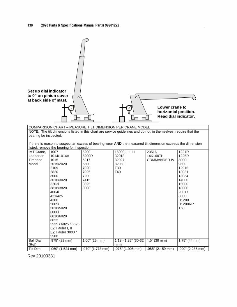
138 2020 Parts & Specifications Manual Part # 99901222
Set up dial indicatorto 0" on pinion coverat back side of mast.
Lower crane tohorizontal position.Read dial indicator.
COMPARISON CHART – MEASURE TILT DIMENSION PER CRANE MODEL
NOTE: The tilt dimensions listed in this chart are service guidelines and do not, in themselves, require that the bearing be inspected. If there is reason to suspect an excess of bearing wear AND the measured tilt dimension exceeds the dimension listed, remove the bearing for inspection.
IMT Crane, Loader or Tirehand Model
1007 1014/1014A 1015 2015/2020 2109 2820 3000 3016/3020 3203i 3816/3820 4004i 421/425 4300 5005i 5016/5020 6006i 6016/6020 6022 5525 / 6025 / 6625 EZ Hauler I, II EZ Hauler 3000 / 5500
5200 5200R 5217 5800 7020 7025 7200 7415 8025 9000
16000-I, II, III 32018 32027 32030 T30 T40
23516 14K160TH COMMANDER IV
1221R 1225R 8000L 9800 12916 13031 13034 14000 15000 18000 20017 8000L H1200 H1200RR T50
Ball Dia. (Ref)
.875" (22 mm) 1.00" (25 mm) 1.18 - 1.25" (30-32 mm)
1.5” (38 mm) 1.75" (44 mm)
Tilt Dim. .060" (1.524 mm) .070" (1.778 mm) .075" (1.905 mm) .085” (2.159 mm) .090" (2.286 mm)
Rev 20100331