Embed Size (px)
Citation preview

20IS709
Communication Systems For Industrial Networking
SCADA

SCADA Examples
Electrical power generation,
transmission and distribution
Manufacturing Building Management Systems
Traffic signals and security systemsMass Transit Water distribution and
treatment plants monitoring
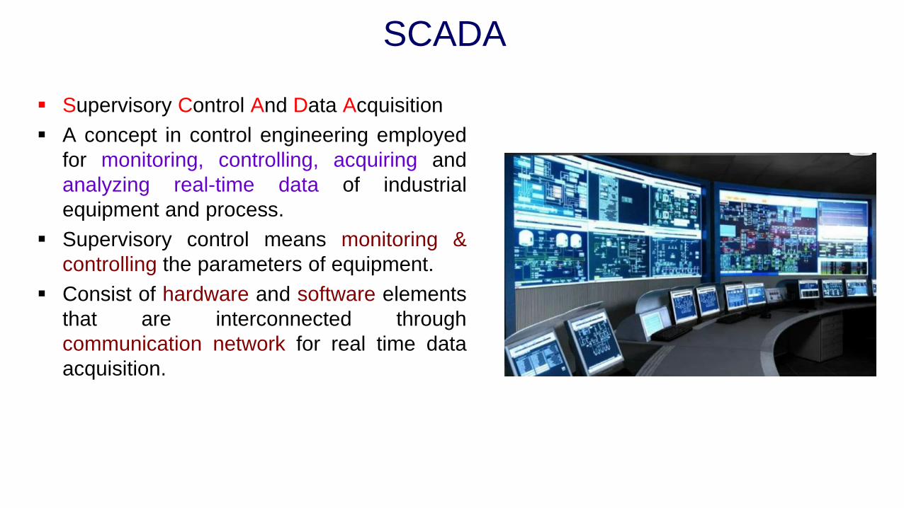
▪ Supervisory Control And Data Acquisition
▪ A concept in control engineering employed
for monitoring, controlling, acquiring and
analyzing real-time data of industrial
equipment and process.
▪ Supervisory control means monitoring &
controlling the parameters of equipment.
▪ Consist of hardware and software elements
that are interconnected through
communication network for real time data
acquisition.
SCADA
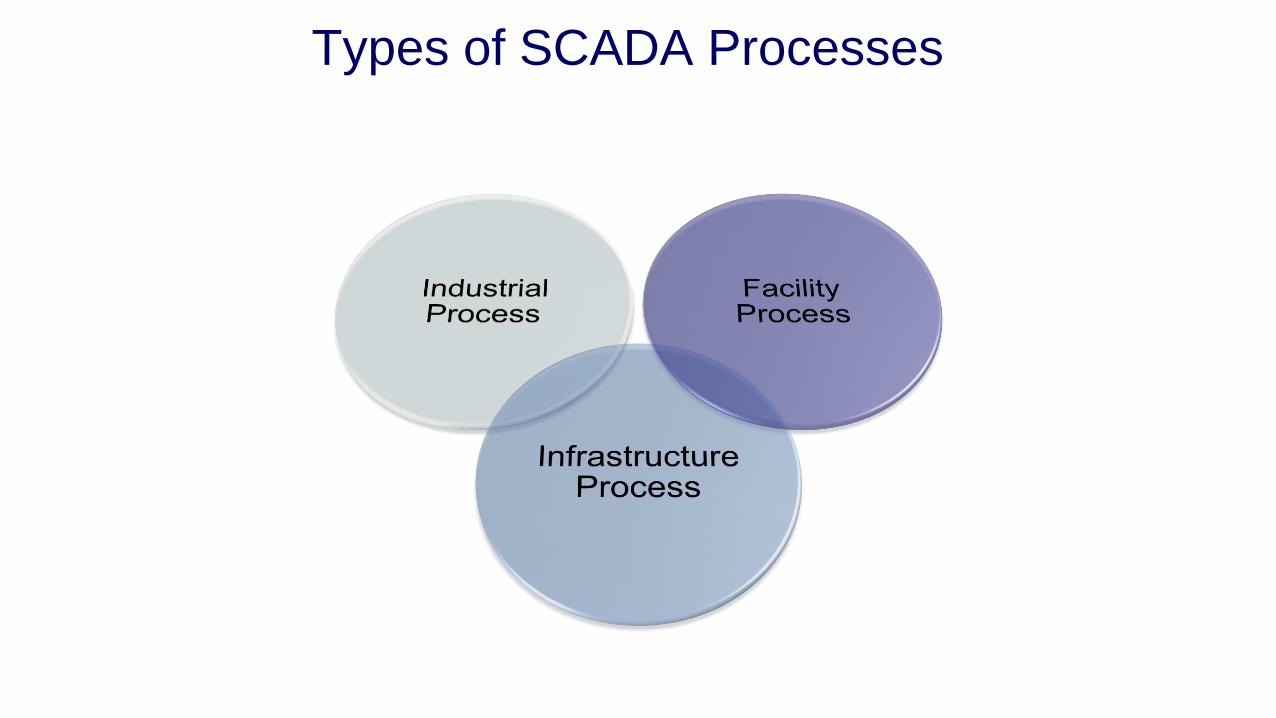
Types of SCADA Processes

Types of SCADA Processes

Components of a SCADA system
Human Machine Interface (HMI)
Supervisory System
Programmable Logic Controllers (PLCs
Remote Telemetry Unit (RTUs)
Communication Infrastructure
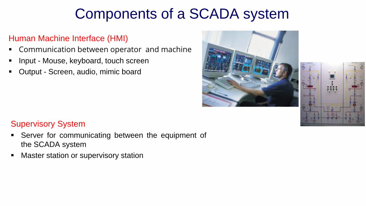
Components of a SCADA system
Human Machine Interface (HMI)
▪ Communication between operator and machine
▪ Input - Mouse, keyboard, touch screen
▪ Output - Screen, audio, mimic board
Supervisory System
▪ Server for communicating between the equipment of
the SCADA system
▪ Master station or supervisory station

Components of a SCADA system
Remote Terminal Units (RTU)
▪ Microprocessor controlled electronic devices
▪ Transmit telemetry data to the supervisory system and
receive the messages from the master system for
controlling the connected objects.
Programmable Logic Controllers
▪ Collecting the sensor output signals in order to convert
the sensor signals into digital data
▪ Economical, versatile, flexible, and configurable than
special-purpose RTUs
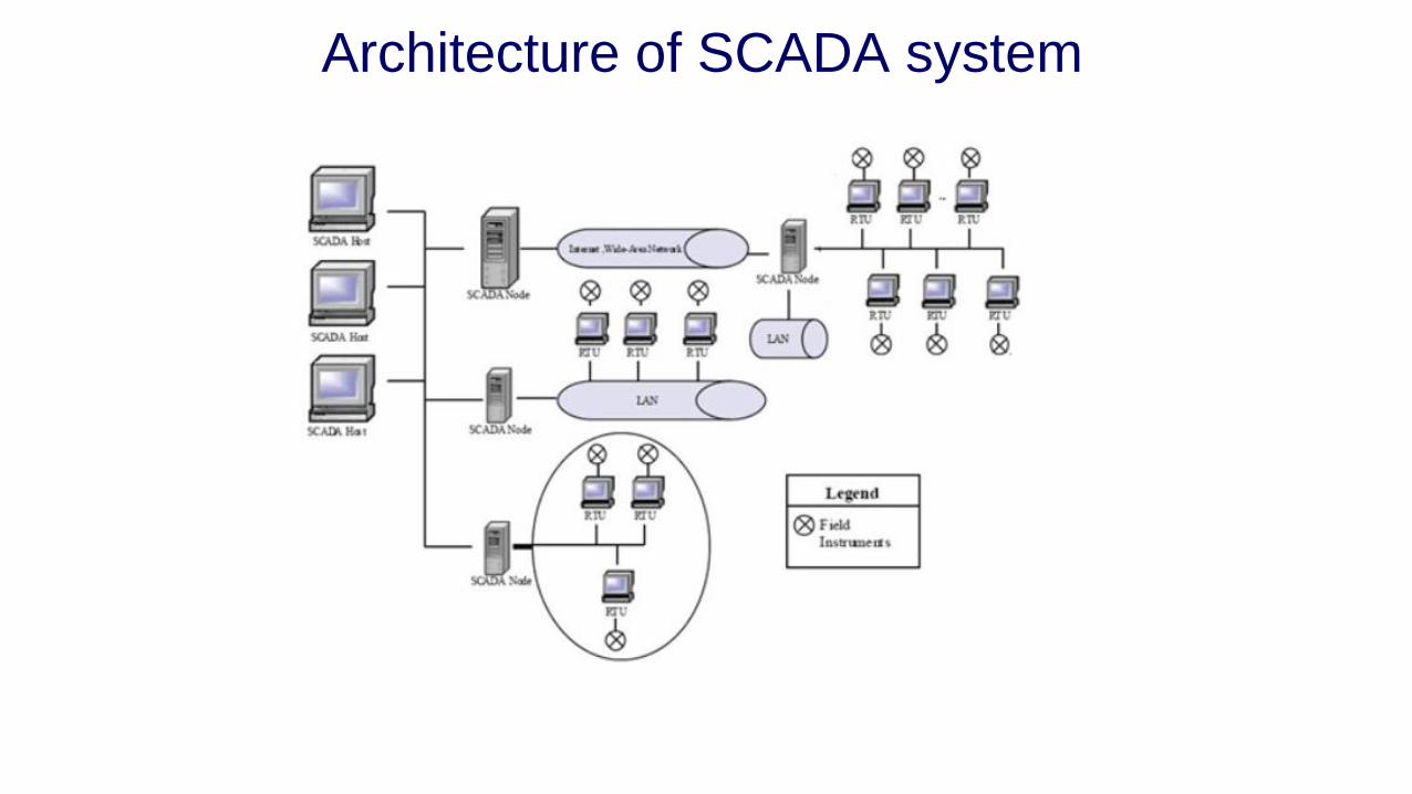
Architecture of SCADA system

Fundamental Principles of SCADA system
Advantages of the PLC / DCS SCADA system are:
▪ The computer can record and store a very large amount of
data
▪ The data can be displayed in any way the user requires
▪ Thousands of sensors over a wide area can be connected
to the system
▪ The operator can incorporate real data simulations into the
system
▪ Many types of data can be collected from the RTUs
▪ The data can be viewed from anywhere, not just on site

Remote Telemetry Unit
Remote terminal units
▪ A standalone data acquisition and
control unit, generally microprocessor
based, which monitors and controls
equipment at some remote location from
the central station
▪ Small sized RTUs generally have less
than 10 to 20 analog and digital signals,
medium sized RTUs have 100 digital
and 30 to 40 analog inputs. RTUs,
having a capacity greater than this can
be classified as large.

Remote Telemetry Unit
Central Processing Unit
▪ Microprocessor based (16 or 32 bit)
▪ Communication ports –two or three ports either RS-232/RS-422/RS-485
▪ Interface to diagnostics terminal
▪ Interface to operator station
▪ Communications link to central site (e.g. by modem)
▪ Real-time clock
▪ Watchdog timer

Remote Telemetry Unit
Analog Input Modules
▪ The input multiplexer
▪ The input signal amplifier
▪ The sample and hold circuit
▪ The A/D converter
▪ The bus interface and board timing system
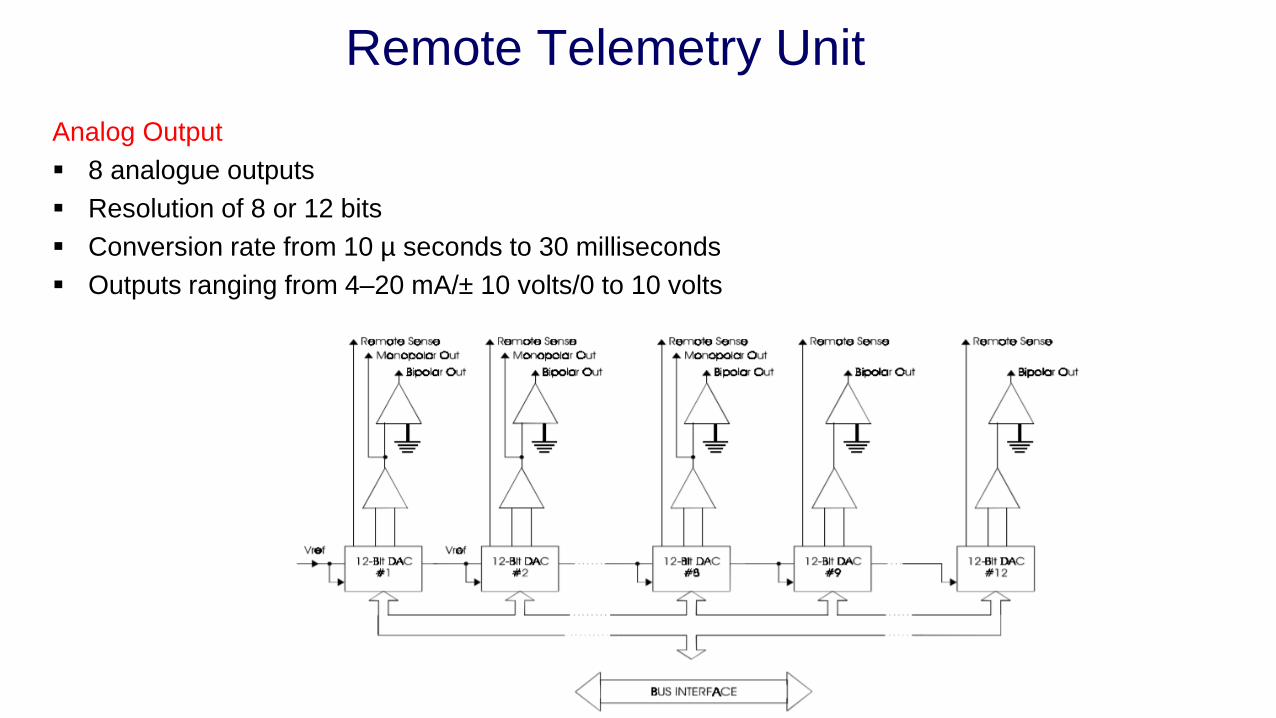
Remote Telemetry Unit
Analog Output
▪ 8 analogue outputs
▪ Resolution of 8 or 12 bits
▪ Conversion rate from 10 µ seconds to 30 milliseconds
▪ Outputs ranging from 4–20 mA/± 10 volts/0 to 10 volts
Remote Telemetry Unit
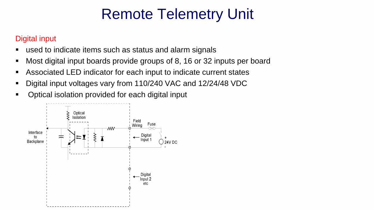
Digital input
▪ used to indicate items such as status and alarm signals
▪ Most digital input boards provide groups of 8, 16 or 32 inputs per board
▪ Associated LED indicator for each input to indicate current states
▪ Digital input voltages vary from 110/240 VAC and 12/24/48 VDC
▪ Optical isolation provided for each digital input
Remote Telemetry Unit
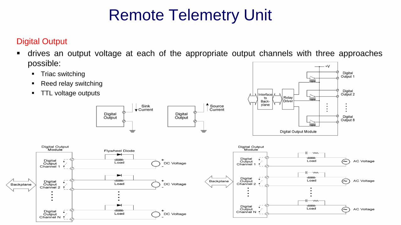
Digital Output
▪ drives an output voltage at each of the appropriate output channels with three approaches
possible:
▪ Triac switching
▪ Reed relay switching
▪ TTL voltage outputs
Remote Telemetry Unit
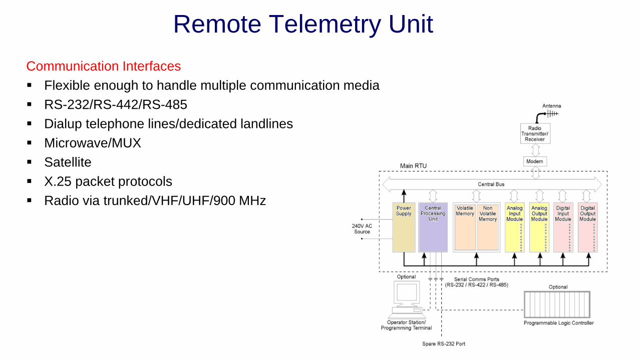
Communication Interfaces
▪ Flexible enough to handle multiple communication media
▪ RS-232/RS-442/RS-485
▪ Dialup telephone lines/dedicated landlines
▪ Microwave/MUX
▪ Satellite
▪ X.25 packet protocols
▪ Radio via trunked/VHF/UHF/900 MHz

Master Station
▪ One or more operator stations connected to a
communication system consisting of modem and radio
receiver/transmitter
Features:
▪ Operator interface to display status of the RTUs and
enable operator control
▪ Logging of the data from the RTUs
▪ Alarming of data from the RTU
Two main functions:
▪ Obtain field data periodically from RTUs and
submaster stations
▪ Control remote devices through the operator station
Master Station
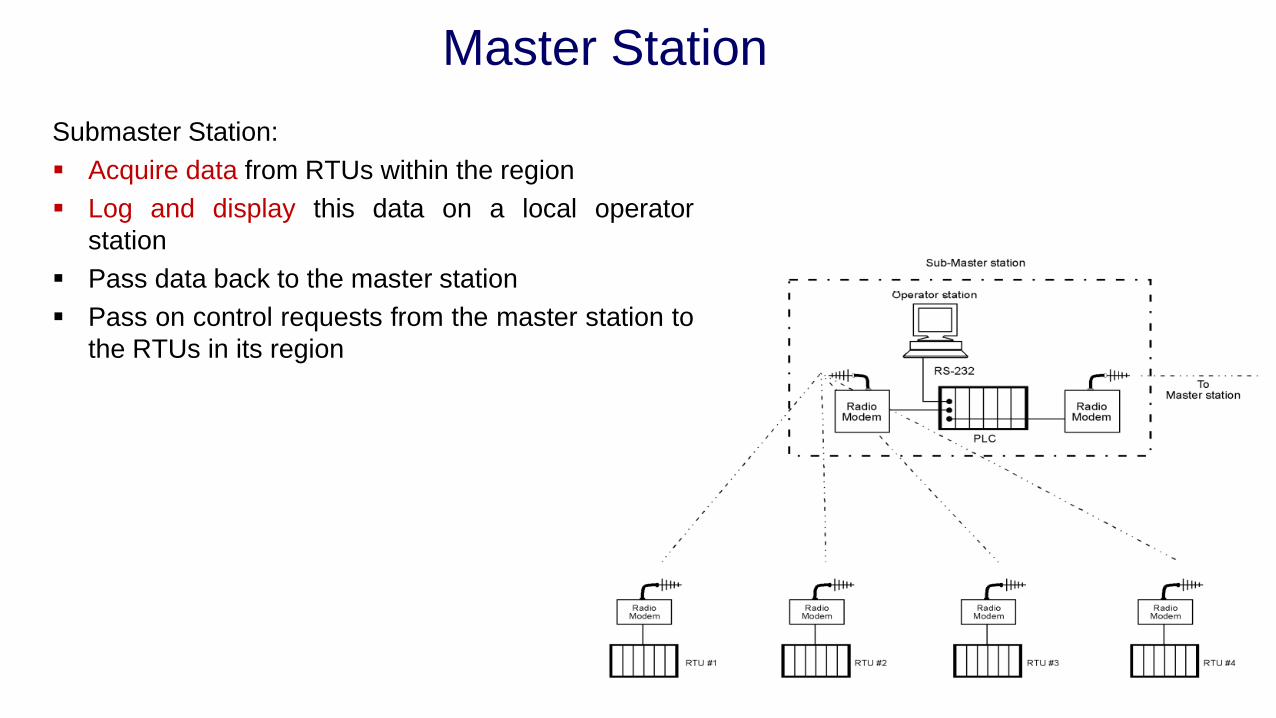
Submaster Station:
▪ Acquire data from RTUs within the region
▪ Log and display this data on a local operator
station
▪ Pass data back to the master station
▪ Pass on control requests from the master station to
the RTUs in its region
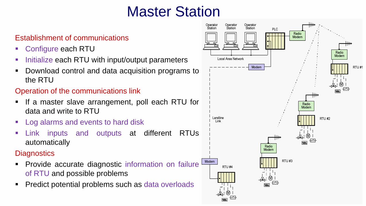
Master Station
Establishment of communications
▪ Configure each RTU
▪ Initialize each RTU with input/output parameters
▪ Download control and data acquisition programs to
the RTU
Operation of the communications link
▪ If a master slave arrangement, poll each RTU for
data and write to RTU
▪ Log alarms and events to hard disk
▪ Link inputs and outputs at different RTUs
automatically
Diagnostics
▪ Provide accurate diagnostic information on failure
of RTU and possible problems
▪ Predict potential problems such as data overloads

SCADA System with Master Station

Master Station
Software
▪ The operating system software
▪ The system SCADA software (suitably configured)
▪ The SCADA application software
System SCADA Software
▪ Data acquisition
▪ Control
▪ Archiving or database storage
▪ The Human machine interface (HMI)
LAN
▪ 802.3 (Ethernet),
▪ 802.4 (token bus) or
▪ 802.5 (token ring)
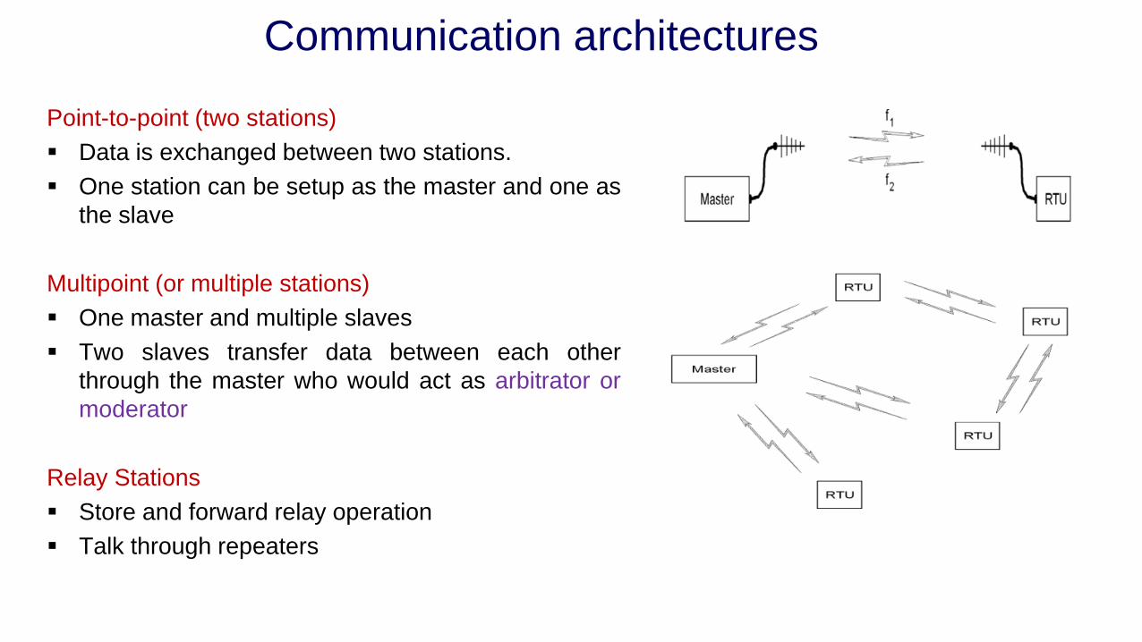
Communication architectures
Point-to-point (two stations)
▪ Data is exchanged between two stations.
▪ One station can be setup as the master and one as
the slave
Multipoint (or multiple stations)
▪ One master and multiple slaves
▪ Two slaves transfer data between each other
through the master who would act as arbitrator or
moderator
Relay Stations
▪ Store and forward relay operation
▪ Talk through repeaters

Communication architectures
Relay Stations
Store and forward relay operation
▪ One station retransmits messages onto another
station out of the range of the master station
Talk through repeaters
▪ Retransmits a radio signal received simultaneously
on another frequency - situated on a
geographically high point.
▪ The repeater receives on one frequency and
retransmits on another frequency simultaneously
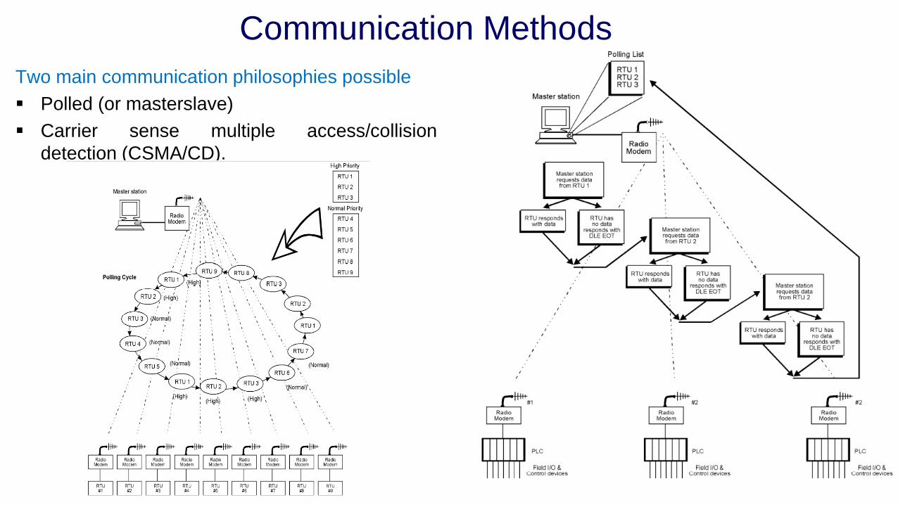
Communication Methods
Two main communication philosophies possible
▪ Polled (or masterslave)
▪ Carrier sense multiple access/collision
detection (CSMA/CD).
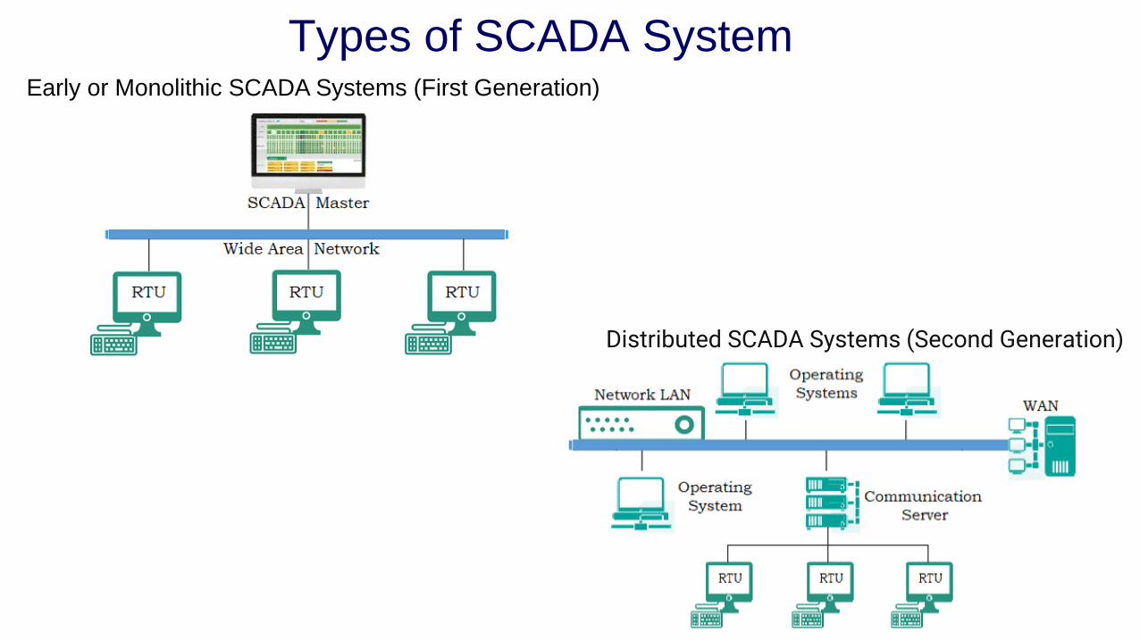
Types of SCADA SystemEarly or Monolithic SCADA Systems (First Generation)
Distributed SCADA Systems (Second Generation)
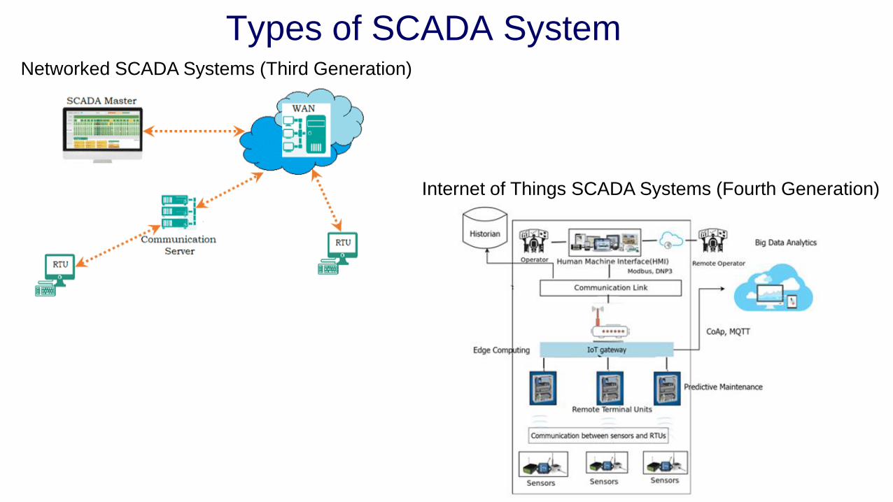
Types of SCADA SystemNetworked SCADA Systems (Third Generation)
Internet of Things SCADA Systems (Fourth Generation)

SCADA software package
▪ Key features expected of the SCADA software
▪ User interface
▪ Graphics displays
▪ Alarms▪ Client server architecture
▪ Time stamped alarms to 1 millisecond precision (or better)
▪ Single network acknowledgment and control of alarms
▪ Alarms are shared to all clients
▪ Alarms displayed in chronological order
▪ Dynamic allocation of alarm pages
▪ Adjustable trip points for each analog alarm
▪ Deviation and rate of change monitoring for analog alarms
▪ Selective display of alarms by category (256 categories)
▪ Historical alarm and event logging
▪ Context-sensitive help
▪ On-line alarm disable and threshold modification
▪ Event-triggered alarms
▪ Alarm-triggered reports
▪ Operator comments can be attached to alarms
▪ Trends
▪ Client server architecture
▪ True trend printouts not screen dumps
▪ Rubber band trend zooming
▪ Export data to DBF, CSV files
▪ X/Y plot capability
▪ Event based trends
▪ Pop-up trend display
▪ Trend gridlines or profiles
▪ Background trend graphics
▪ Real-time multi-pen trending
▪ Short and long term trend display
▪ Length of data storage and frequency of monitoring can be
specified on a per-point basis
▪ Archiving of historical trend data
▪ On-line change of time-base without loss of data
▪ On-line retrieval of archived historical trend data
▪ Exact value and time can be displayed
▪ Trend data can be graphically represented in real-time

SCADA software package▪ Key features expected of the SCADA software
▪ RTU (and PLC) interface▪ All compatible protocols included as standard
▪ DDE drivers supported
▪ Interface also possible for RTUs, loop controllers, bar code readers and other equipment
▪ Driver toolkit available
▪ Operates on a demand basis instead of the conventional predefined scan method
▪ Optimization of block data requests to PLCs
▪ Rationalization of network user data requests
▪ Maximization of PLC highway bandwidth
▪ Scalability▪ Additional hardware can be added without replacing or modifying existing equipment
▪ Limited only by the PLC architecture (typically 300 to 40 000 points)
▪ Access to data▪ Direct, real-time access to data by any network user
▪ Third-party access to real-time data, e.g. Excel
▪ Network DDE, DDE compatibility: read, write and exec
▪ DDE to all IO device points
SCADA software package
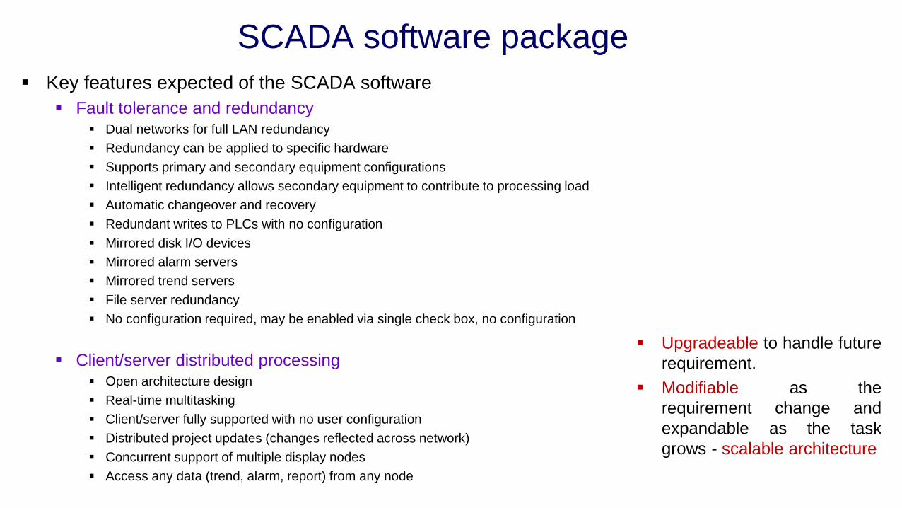
▪ Key features expected of the SCADA software
▪ Fault tolerance and redundancy▪ Dual networks for full LAN redundancy
▪ Redundancy can be applied to specific hardware
▪ Supports primary and secondary equipment configurations
▪ Intelligent redundancy allows secondary equipment to contribute to processing load
▪ Automatic changeover and recovery
▪ Redundant writes to PLCs with no configuration
▪ Mirrored disk I/O devices
▪ Mirrored alarm servers
▪ Mirrored trend servers
▪ File server redundancy
▪ No configuration required, may be enabled via single check box, no configuration
▪ Client/server distributed processing▪ Open architecture design
▪ Real-time multitasking
▪ Client/server fully supported with no user configuration
▪ Distributed project updates (changes reflected across network)
▪ Concurrent support of multiple display nodes
▪ Access any data (trend, alarm, report) from any node
▪ Upgradeable to handle future
requirement.
▪ Modifiable as the
requirement change and
expandable as the task
grows - scalable architecture

SCADA software packageTwo main approaches in designing the SCADA system
▪ Centralized processing ▪ Distributed processing
▪ Single computer or mainframe performs all plant
monitoring and all plant data is stored on one database
▪ Initial up front costs are fairly high for a small system
▪ A gradual approach to plant upgrading is not really
possible due to the fixed size of the system
▪ Redundancy is expensive as the entire system must be
duplicated
▪ Shared across several small computers
▪ Communication between different computers is
not easy, resulting in configuration problems
▪ Data processing and databases duplicated
across all computers resulting in low efficiencies
▪ There is no systematic approach to acquiring
data from the plant devices

SCADA software packageClient server approach
▪ Server node is a device that provides a service to other nodes on the network - database program
▪ Client is a node that requests a service from a server
▪ Display node (or client) requests the data from the control server which then searches the
database and returns the data requested, thus reducing the network overhead.

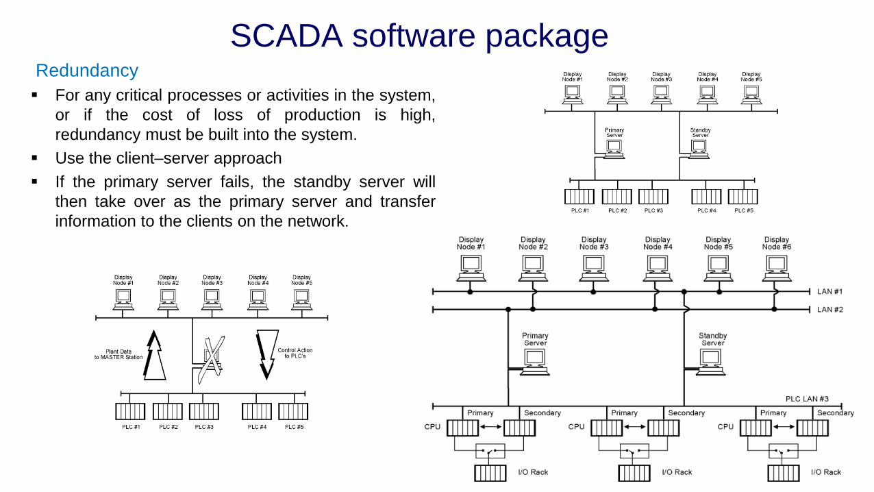
SCADA software packageRedundancy
▪ For any critical processes or activities in the system,
or if the cost of loss of production is high,
redundancy must be built into the system.
▪ Use the client–server approach
▪ If the primary server fails, the standby server will
then take over as the primary server and transfer
information to the clients on the network.

SCADA software packageSystem response time
▪ Typical speeds that are considered acceptable are:
▪ Display of analog or digital value (acquired from RTU) on the master station operator display (1 to 2 seconds
maximum)
▪ Control request from operator to RTU (1 second critical; 3 seconds non-critical)
▪ Acknowledge of alarm on operator screen (1 second)
▪ Display of entire new display on operator screen (1 second)
▪ Retrieval of historical trend and display on operator screen (2 seconds)
▪ Sequence of events logging (at RTU) of critical events (1 millisecond)
▪ The response is consistent over all activities of the SCADA system.
▪ Distributed approach to the design of the SCADA system ensures that these response time can be easily
achieved
Expandability of the system
▪ Additional hardware will be of the same modular form, and will not impact on the existing hardware installed.
▪ Operating system will be able to support the additional requirements without any major modifications.
▪ Application software should require no modifications in adding the new RTUs or operator stations at the
master station.
Reference
1. David Bailey Edwin Wright, “Practical SCADA for Industry”, 1st Edition, Elsevier, 2003.


![Industrial Networking Systems. - Indico [Home]indico.ictp.it/event/a05231/session/52/contribution/35/material/0/... · Industrial Networking Systems ... and communication protocols](https://img.pdfslide.net/doc/110x75/5ae1d7ae7f8b9a5d648beab1/industrial-networking-systems-indico-home-networking-systems-and-communication.jpg)