Embed Size (px)
Citation preview
PART c: Airspace Protection
21.0
148
21 AIRSPAcE PROTEcTION
21.1 AIRSPAcE PROTEcTION OVERVIEW
The protection of the airspace surrounding airports is a critical component of maintaining a safe operating environment for both current traffic types and levels as well as for future traffic types and levels.
consequently, it is necessary to restrict some types of development and land uses in the vicinity of airports. This ensures that airspace required to facilitate aircraft operations remain obstacle free and hence contribute to the safety and efficiency of those operations.
In order to facilitate broad community understanding of these restrictions, the following aspects are provided below:
• description of the regional airspace and operatingprocedures;
• prescribedairspace(OLSandPANS-OPS);
• externallightinglimitations;and
• stackandventeffluxlimitations.
21.2 REgIONAL AIRSPAcE
21.2.1 overview
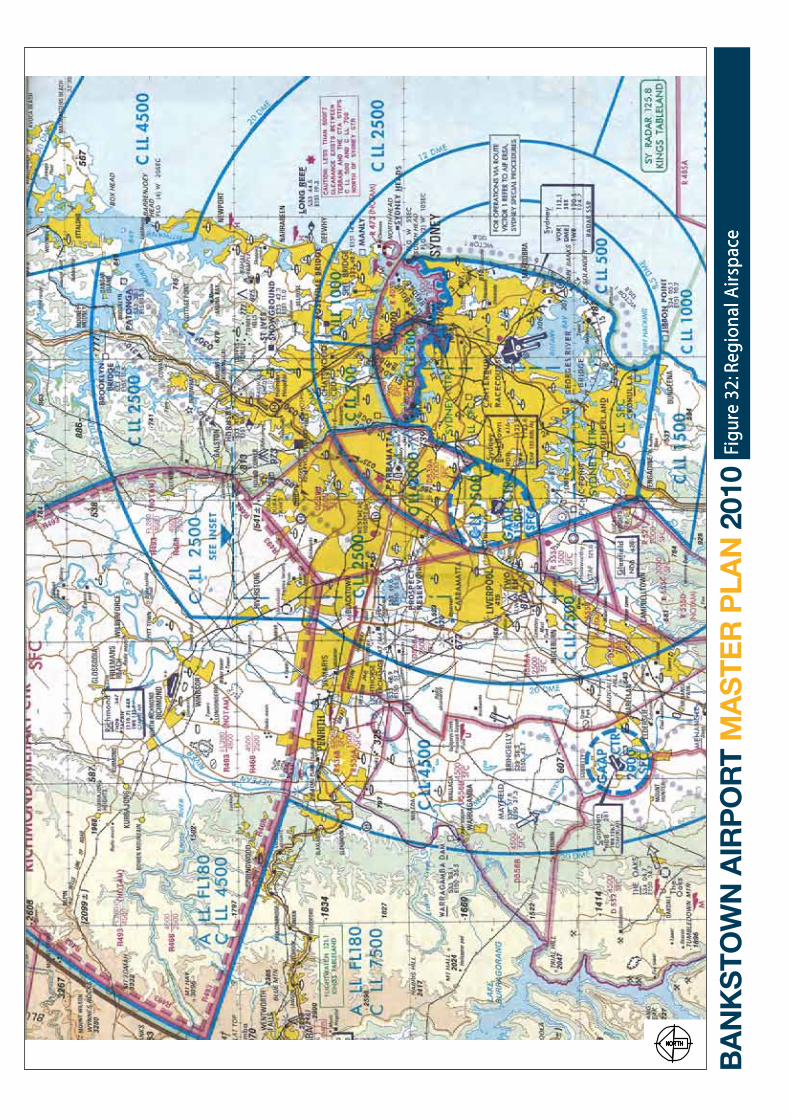
Airservices Australia is responsible for airspace management within the Sydney Basin, as well as elsewhere in Australia. The airspace within the Sydney Basin is dominated by the Sydney Airport control Zone (cTR) and the requirement to efficiently manage the large volume of domestic and international aircraft movements into and out of that airport.
The Sydney Airport control Area (cTA) is comprised of a series of controlled airspace blocks, ascending in vertical steps, and extending out to a maximum radius of 45 nautical miles (NM) at its greatest dimension. The Airservices Australia Sydney Terminal control Unit (TcU) provides traffic management and separation within the airport cTA and cTR. Aircraft take off and landing clearances, as well as ground movements, are handled by the Sydney control Tower.
The Bankstown Airport cTR extends out 3 NM from the airport, except where it would otherwise overlap the Sydney Airport cTR to the east. To prevent overlapping cTRs, the Bankstown control Zone is truncated to approximately 2 NM from the airport. The ability of Bankstown and Sydney Airports to operate independently is predicated on the ability of aircraft using Bankstown to remain within the airport’s cTR and to not infringe on Sydney Airport airspace.
Under visual flight rule (VfR) conditions when the Air Traffic control Tower (ATcT) is in operation, all aircraft operating at Bankstown are required to follow general Aviation Airport Procedures (gAAP) within the airport’s cTR. When the ATcT is closed, pilots are required to broadcast their position in accordance with the common Traffic Advisory frequency (cTAf). During instrument fight rule (IfR) conditions, the Sydney TcU provides separation services for instrument arrivals and departures at Bankstown. However, IfR traffic into and out of Bankstown must be managed in association with and sequenced relative to aircraft traffic at Sydney Airport.
The proximity of Bankstown Airport and Sydney Airport, combined with the orientation of runways at the two airports create the potential for airspace conflicts under certain combinations of conditions and flight operations. In 1998, the Minister of Transport and Regional Development advised Airservices Australia that Sydney International Airport operations should be given priority over those at Bankstown Airport, as well as other airports in the Sydney Basin. Since that time, airspace and air traffic management procedures have given precedence to accommodating traffic at Sydney International Airport.
Of the remaining airports in the Sydney Basin, camden Airport has cTR and gAAP procedures, which are used to maintain traffic separation during the hours the control tower is in operation. When the control tower is closed, cTAf are in effect. Hoxton Park Airport closed in December 2008 and a number of aviation businesses transferred their operations to camden, Bankstown Airport or to other locations. RAAf Richmond has a control tower and cTR. In its south east quadrant, the Richmond cTR abuts portions of the Sydney cTR.
PART c: ISSUES MANAgEMENT
149
Airservices Australia has established a Lane of Entry (LOE) to the Bankstown cTR, which allows aircraft access to and from Bankstown without needing to enter the control Zones surrounding RAAf Richmond and Sydney Airport. The LOE is a corridor of airspace 8 to 10 NM in width and a ceiling height of 2,000 to 2,500 feet. Additionally, the LOE may also be used by smaller aircraft wishing to transit from north of Sydney to areas south and south west of the city.
There are six flying training areas within the Sydney Basin. The areas are encompassed by a line extending from the western boundary of the Bankstown cTR to the Richmond cTR then to the Blue Mountains, camden, and back to the Bankstown cTR. The training areas are designated (class g) uncontrolled airspace which extends from the surface up to the base of the overlying cTA step at 4,500 feet. Bankstown and camden Airports are reported to be the predominant source of flying training activity using this area.
Regional airspace allocations within the Sydney Airport cTR are depicted in figure 32.
21.2.2 local airspace and air traFFic control
As discussed above, Bankstown is a gAAP cTR with a vertical limit of 1,500 feet and a nominal radius of 3 nautical miles. To avoid overlapping cTRs, the Bankstown cTR is truncated to 2 NM where it abuts the Sydney International Airport cTR. flight procedures at Bankstown are normally conducted so as to avoid aircraft entry into the Sydney International cTR unless specific clearances have been received to do so from the Sydney TcU.
When the Bankstown cTR is active, i.e. when the ATcT is in operation, aircraft are not authorised to enter the cTR without a clearance from the tower.
There are two designated gAAP approach points and associated routes identified in the Airservices Australia Enroute Supplement for Bankstown:
• ProspectReservoirtothenorth-west,onatrackof136degrees M; and
• abeamthe2RNradiotransmittertothesouthwest,ona track of 057 degrees M.
The gAAP Prospect approach route serves as an entry for aircraft arriving from the north west, including those returning from the designated flying training areas. The gAAP 2RN approach route is the entry point for traffic arriving from the south and west.
A Bankstown Lane of Entry (LOE) has been established to create a corridor for light aircraft access to and from the Bankstown cTR without entering the adjacent controlled airspace for Sydney Airport and RAAf Richmond. In addition, the Bankstown LOE provides a corridor outside controlled airspace for light aircraft transiting between areas north of Sydney and areas to the south and south west of Sydney.
The LOE specifies vertical limits on operating altitude to ensure adequate aircraft separation from overlying controlled and restricted airspace. When using the LOE, pilots must operate VfR and comply with general flight rules regarding terrain clearance, and flights over populated and low-level restricted areas.
As already noted in the discussion of regional airspace above, the area west of Bankstown to the Warragamba Dam/Lake Burragorang and bounded by the great Western and Hume Highways is a designated flying training area. This flying training area is reported to be heavily used by aircraft from Bankstown Airport.
Technologies such as area navigation (RNAV) using the global Navigation Satellite System (gNSS) may eventually create long-term solutions by allowing curved approaches, which could offer air traffic management procedures not presently available.
On 15 July 2009 cASA released the final report into the Utility of general Aviation Aerodrome Procedures (gAAP) to Australian Administered Airspace. The study was commissioned to review airspace management in relation to gAAP as used at Bankstown and other capital city secondary aerodromes. This and other studies into airspace management and ATS at gAAP aerodromes resulted in cASA directing Airservices
Figu
re 3
2: R
egio
nal A
irsp
ace
Figu
re 3
2: R
egio
nal A
irsp
ace
151
Australia to implement changes to air traffic services and airspace management as described in 25.2.3, including implementation of full class D airspace air traffic services. The directions form part of cASA’s ongoing efforts to improve safety at gAAP aerodromes and will affect the level of aviation activity at Bankstown but it was not possible to estimate their impact when this PDMP was prepared.
21.2.3 air traFFic control
The air traffic control tower operates generally from 6:00am until 9:00pm Monday through friday, and 6:00am to 8:00pm Saturday and Sunday. Aircraft wishing to enter the Bankstown cTR must obtain a clearance from the tower prior to entry. Outside tower hours the gAAP cTR reverts to a cTAf.
Essentially there are three parallel runways which operate as a single entity. Under visual conditions, the outer runways are operated simultaneously with contra-rotating circuits. One runway, typically Runway 11L/29R, provides for arrival and departures while the other runway, Runway 11R/29L, is used for circuit training or touch and go operations.
circuit training, which involves repetitious operations, is directed to runway 11R/29L for noise abatement reasons. This allows the aircraft to overfly primarily open space and commercial/industrial properties. Arrivals and departures are managed on runway 11L/29R with aircraft departing from or joining circuits to the north of the airport.
circuits are conducted at 1,000 feet. Aircraft departing Bankstown do so by extending the upwind, crosswind or downwind leg of the circuit, tracking clear of the gA approach points and the associated inbound routes. Departures from runway 11 leave the cTR on climb to 1,500 feet, and departures from runway 29 maintain 1,000 feet until clear of the cTR.
When runway 29 is in use, arriving aircraft enter the cTR at 1,500 feet and maintain this altitude until on the downwind leg of the circuit abeam the upwind end of
the runway. When runway 11 is in use, aircraft arriving from Prospect or 2RN enter the cTR at 1,000 feet. This guarantees vertical separation of conflicting traffic.
At night or in instrument conditions, all operations are confined to the central runway (Runway 11c/29c).
On 21 July 2009, based on the findings of a recently commissioned review of airspace management, cASA issued a direction to Airservices Australia for the staged implementation of revised procedures at gAAP aerodromes, including Bankstown Airport. changes introduced on 21 July were:
• Animmediatelimitationonthenumberofaeroplanesin the circuit for one runway, controlled by one Air Traffic controller, to six. If two runways and two controllers are available then the total number of aeroplanes in the circuit would be limited to 12. An additional departure may be permitted at the discretion of the controller having given due consideration to all relevant safety factors;
• AnimmediaterequirementforallaircrafttoobtainanAir Traffic control clearance to enter, cross or taxi along any runway, and
• The provision (within 9 months) of aerodrome ATSdaily for the hours of daylight without any reduction in the service currently provided during the hours of darkness.
It is presently not possible to anticipate how or when the recommendations in the reports leading to the cASA direction will be implemented. This PDMP has been prepared on the basis of the current gAAP procedures, being the best available information at the present time. The changes directed by cASA will reduce the level of aviation activity in comparison to that forecast in this PDMP but the way in which the airspace around Bankstown Airport will operate in the future will not become clear for the next 3 to 5 years. These airspace changes will therefore be incorporated into the next five-year Master Plan in 2015.
152
21.2.4 availaBle approaches
All instrument approach procedures to Bankstown Airport are non-precision approaches. As a result, the minimum pilot decision heights are relatively high compared to precision instrument approaches. The lowest classification of precision instrument approach is category I, which provides a minimum decision height of 200 feet.
taBle 13 - availaBle approaches at Bankstown airport
In addition to the published non-precision approaches, there are two Standard Arrival Routes (STARs) for Bankstown. The WATLE four Arrival is for aircraft arriving from the west and the Richmond four Arrival is for aircraft arriving from the north to north west. Standard Instrument Departure procedures (SIDs) are published for Bankstown runways 11c and 29c.
21.2.5 Flightpaths
flight paths were not required to be, and were not, depicted in the2005 MP. However, when the Airports Act 1996 was amended in May 2007, a new provision was added which requires flight paths to be set in draft and final master plans (but not in a proposed variation to an existing MP). See Section 24.3.4.
21.3 PREScRIBED AIRSPAcE
The Airports Act 1996 requires the production of prescribed airspace plans for airports. Under the Airports (Protection of Airspace) Regulations, prescribed airspace is defined as airspace above any part of the OLS
or PANS-OPS surfaces, whichever represents the lower airspace surface.
The object of prescribed airspace is to ensure that the airport is not adversely affected by the building of structures in the area used by arriving and departing aircraft. The prescribed airspace plan which represents the OLS and PANS-OPS surfaces gives airport operators guidance in protecting critical surfaces that affect instrument approach minimum altitudes.
21.3.1 ols
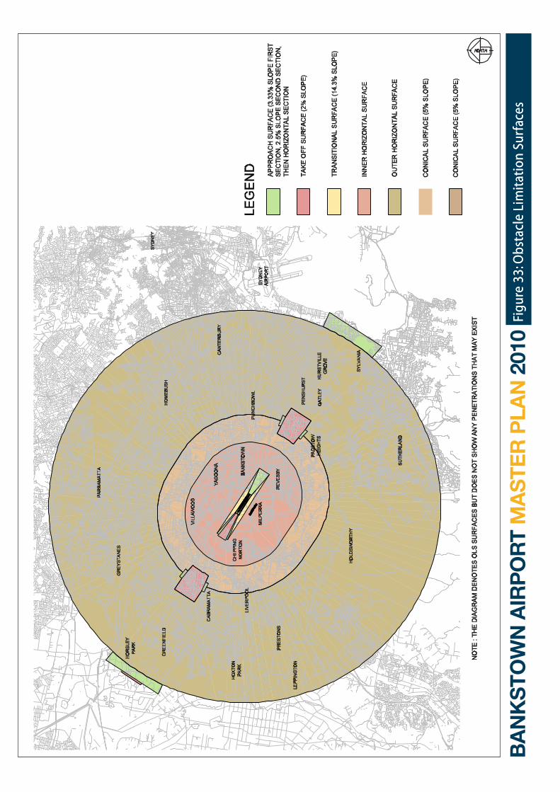
The OLS at Bankstown Airport are defined under the cASA MOS Part 139 – Aerodromes, Section 7.3 and they are established in accordance with International Civil Aviation Organization (ICAO) specifications. TheOLS comprise a series of imaginary planes surrounding an airport which must be kept free and clear of obstructions that could be hazardous to aircraft takingoff or landing at the facility. The surfaces are intended to prevent development of airspace obstructions that could adversely impact air navigation or the usability of the facility. The height restrictions imposed by the OLS are determined based on the following factors:
• theintendeduseoftherunway,i.e.fortake-off,landingor both;
• therunwaycodeasdeterminedbytherunwaylengthand type of aircraft using the runway; and
• typeofapproach,i.e.non-instrument,nonprecisionorprecision instrument.
Extending off the end of each runway, the OLS standards define both a “take-off climb” surface and an “approach surface” for landing. Where take-offs and landings may occur in either direction along a runway, the more restrictive approach surfaces for landings should be used in determining obstacle height restrictions. At Bankstown Airport, it is assumed that take-offs and landings may occur in either of the runway directions and therefore the landing approach surfaces are used in this analysis.
Surrounding the runway pavement is the Runway Strip.
PART c: ISSUES MANAgEMENT
Published Approach Type Minimum Decision Height (in feet AgL)
Runway 11c NDB/Sy DME
NDB (Note: gPS may be used in lieu of Sy DME)
code A, B, c aircraft – 651 feet
Radar One/ BK NDB circling Approach code A, B – 881 feet code c - 911
Radar Two/ BK NDB/Sy VOR
circling Approach code A, B – 881 feet code c - 911
Runway 11c gPS gPS code A, B, c aircraft – 651 feet
Sydney VOR/ BK NDB circling Approach code A, B – 881 feet code c - 911
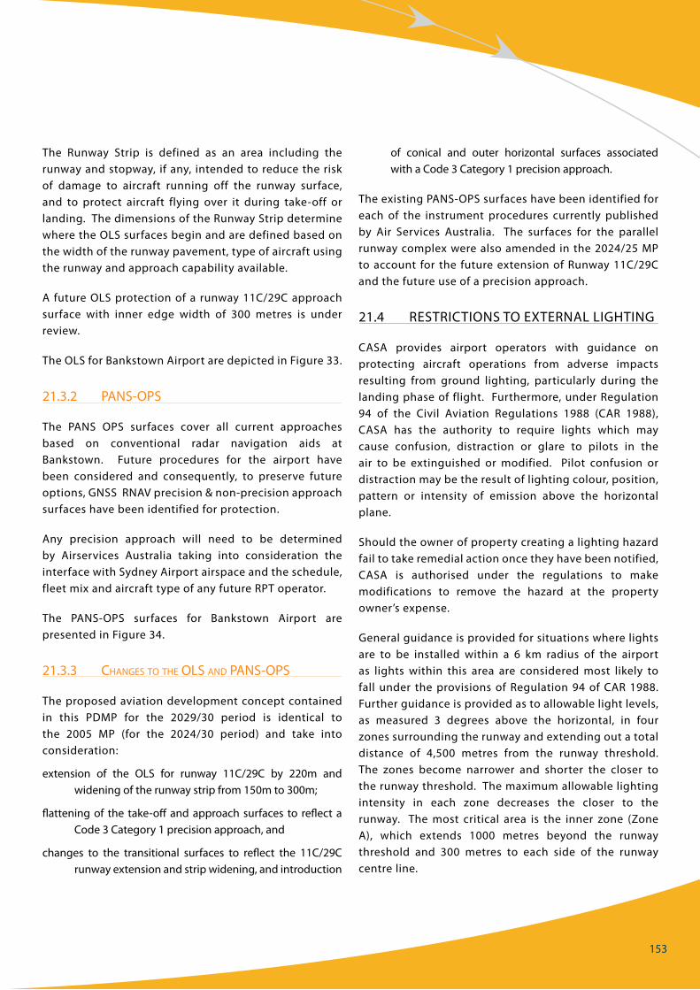
153
The Runway Strip is defined as an area including the runway and stopway, if any, intended to reduce the risk of damage to aircraft running off the runway surface, and to protect aircraft flying over it during take-off or landing. The dimensions of the Runway Strip determine where the OLS surfaces begin and are defined based on the width of the runway pavement, type of aircraft using the runway and approach capability available.
A future OLS protection of a runway 11c/29c approach surface with inner edge width of 300 metres is under review.
The OLS for Bankstown Airport are depicted in figure 33.
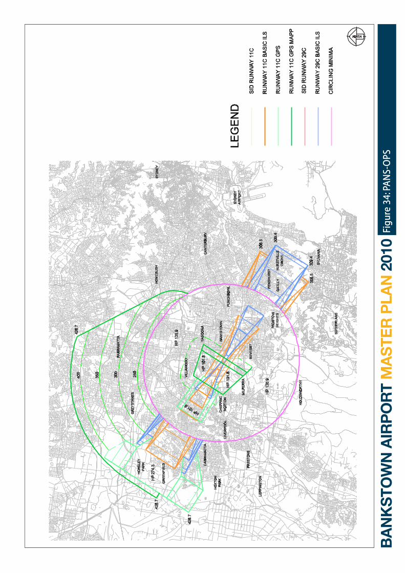
21.3.2 pans-ops
The PANS OPS surfaces cover all current approaches based on conventional radar navigation aids at Bankstown. future procedures for the airport have been considered and consequently, to preserve future options, gNSS RNAV precision & non-precision approach surfaces have been identified for protection.
Any precision approach will need to be determined by Airservices Australia taking into consideration the interface with Sydney Airport airspace and the schedule, fleet mix and aircraft type of any future RPT operator.
The PANS-OPS surfaces for Bankstown Airport are presented in figure 34.
21.3.3 changes to the ols and pans-ops
The proposed aviation development concept contained in this PDMP for the 2029/30 period is identical to the 2005 MP (for the 2024/30 period) and take into consideration:
extension of the OLS for runway 11c/29c by 220m and widening of the runway strip from 150m to 300m;
flattening of the take-off and approach surfaces to reflect a code 3 category 1 precision approach, and
changes to the transitional surfaces to reflect the 11c/29c runway extension and strip widening, and introduction
of conical and outer horizontal surfaces associatedwith a code 3 category 1 precision approach.
The existing PANS-OPS surfaces have been identified for each of the instrument procedures currently published by Air Services Australia. The surfaces for the parallel runway complex were also amended in the 2024/25 MP to account for the future extension of Runway 11c/29c and the future use of a precision approach.
21.4 RESTRIcTIONS TO ExTERNAL LIgHTINg
cASA provides airport operators with guidance on protecting aircraft operations from adverse impacts resulting from ground lighting, particularly during the landing phase of flight. furthermore, under Regulation 94 of the civil Aviation Regulations 1988 (cAR 1988), cASA has the authority to require lights which may cause confusion, distraction or glare to pilots in the air to be extinguished or modified. Pilot confusion or distraction may be the result of lighting colour, position, pattern or intensity of emission above the horizontalplane.
Shouldtheownerofpropertycreatingalightinghazardfail to take remedial action once they have been notified, cASA is authorised under the regulations to make modifications to remove the hazard at the propertyowner’s expense.
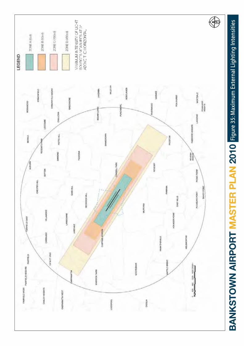
general guidance is provided for situations where lights are to be installed within a 6 km radius of the airport as lights within this area are considered most likely to fall under the provisions of Regulation 94 of cAR 1988. further guidance is provided as to allowable light levels, as measured 3 degrees above the horizontal, in fourzonessurroundingtherunwayandextendingoutatotaldistance of 4,500 metres from the runway threshold. The zones become narrower and shorter the closer tothe runway threshold. The maximum allowable lighting intensity in each zone decreases the closer to therunway. Themost critical area is the inner zone (ZoneA), which extends 1000 metres beyond the runway threshold and 300 metres to each side of the runway centre line.
Figu
re 3
3: O
bsta
cle
Lim
itat
ion
Surf
aces
Figu
re 3
3: O
bsta
cle
Lim
itat
ion
Surf
aces
Figu
re 3
4: P
AN
S-O
PSFi
gure
34:
PA
NS-
OPS
156
Potential conflicts or distractions caused by lighting colour are noted as independent from lighting intensity as some colours may cause confusion with airport lighting.
Adverse impacts from ground lighting can often be associated with outdoor advertising displays, sports field lighting and street lighting. At present, no adverse impacts from ground light emissions are known to exist at the airport. Lighting associated with future development in the airport vicinity should conform to the provisions of regulation 94 of the cAR.
To assist developers, lighting designers and installation contractors in the vicinity of airports, BAL has prepared a plan highlighting maximum lighting intensities in areas surrounding Bankstown Airport. This is presented in figure 35. External advertising, sports field floodlighting and street lighting are some of the more likely lighting sources requiring consideration. BAL will consult and liaise with Bankstown city council, and other councils as appropriate, on the most appropriate mechanism for ensuring that external lighting does not adversely impact on Airport operations.
21.5 STAcK AND VENT EffLUx
cASA has identified the need to assess the potential hazard to aviationwhere the vertical velocity fromgasefflux may cause airframe damage and/or affect the handling characteristics of an aircraft in flight. This is especially critical during periods of high pilot workload or when the aircraft is being manoeuvered at low altitudes, particularly with flaps extended and/or gear down.
Typically this includes the initial take-off climb or approach to land, when the aircraft is in the vicinity of an airport.
In some cases the high efflux temperature or velocity may cause air disturbance at higher altitudes. If so, cASA also requires an assessment of the potential for the exhaust plume to affect the safe handling of aircraft
in other phases of flight.
The draft cASA Advisory circular Ac 139-05(0) provides airport operators with guidance for assessing possible adverse impacts of gas efflux on aircraft operations in the vicinity of the airport. Plumes with a vertical velocity greater than 4.3 metres/second may cause airframe damage to aircraft during critical stages of flight, such as landing with full flaps extended.
Proponents of a facility to be located within 15 kilometres of an airport are to consult the airport operator if that facility includes a combustion source which generates an exhaust plume which has a vertical velocity greater than 4.3 metres/second at the OLS.
The Advisory circular notes that plumes exceeding 4.3 metres/second vertical velocity at the Obstacle Limitation Surface, or 360 feet above ground level (AGL) should be deemed a potential hazard to aircraftand identified as an “obstacle” in accordance with the provisions of cASR Part 139.
The hazards addressed in the Advisory Circular aretypically associated with industrial processes. At Bankstown Airport, there are no known sources of gas efflux or plumes that would constitute a hazard toaircraft operating at the airport. The Airports Act 1996 also provides for protection of airspace against stack and vent efflux. BAL will consult and liaise with Bankstown city council, and other councils as appropriate, on the most appropriate mechanism so that stack and vent efflux does not adversely impact on Airport operations.
PART c: ISSUES MANAgEMENT
Figu
re 3
5: M
axim
um E
xter
nal L
ight
ing
Inte
nsit
ies
Figu
re 3
5: M
axim
um E
xter
nal L
ight
ing
Inte
nsit
ies

PART c: Implementation
22.0
160
22 IMPLEMENTATION
22.1 gENERAL
The aviation and land development concepts outlined in this PDMP represent current views of development expected to be realised in a staged manner, largely as a result of increased aircraft movements, movement area asset management and property initiatives.
As set out in the Airports Act 1996, developments as described in Section 19.6 or Major Development Plans for designated major airport developments are required for approval. Major airport developments are the subject of further community consultation, environmental assessment and Ministerial approval.
This PDMP provides a 20 year strategic planning framework for the future development of the Airport. It demonstrates the necessary flexibility to ensure that future aviation and property industry trends and demands are appropriately met through the provision of new or enhanced infrastructure in a timely manner. Below is an indicative summary of the potential proposals associated within the first five years of this PDMP.
The actual timing of each of the developments will depend on:
• the assessment of prevailing and forecast marketconditions,
• thedemandtriggers,
• abusinesscaseoranassetmanagementcase,
• the carrying out of any necessary environmentalassessment and approvals processes and
• theoutcomeofstakeholderconsultationprocesses.
Land is developed by BAL, by BAc Devco, or by sub-lessees or third party developers under commercial development agreements. All developments must be approved by BAL with building approval by the Airport Building controller.
22.2 PROPOSALS TO 2015
Potential proposals within the period to 2015 are described below as:
• AviationDevelopmentConceptProposals;
• BALLandDevelopmentConceptProposals;
• Sub-lessee or Third Party Property DevelopmentProposals, and
• InfrastructureProvisions.
22.2.1 aviation developMent concept proposals (see section 11)
The following aviation proposals are expected to be undertaken during the period 2010 to 2015:
Aviation Precinct
• Runway resheet RWY Centre Mar 2010, North RWY2011/12
• SealedRESA’sFY11/12
• Aircraftwashdownbayandenginerunupbay
• ExpansionofCCTVsystemFY09/10
• ApronSealingFY12/13
North-West Precinct
• upgradeoftheexistingterminal(seeSection10.2)FY10/11
• construction of at-grade car parks adjacent to theterminal fy 10/11
• introduction of paid controlled car parking on thenorthern side of Airport fy 10/11
• hangardevelopmenttothenorthwestoftherunways
• on grade vehicle parking to the north west of therunways
• AirportAvenueroadlayoutimprovementFY11/12.
North-East Precinct
• developmentofthe“northairsite”tothenorthoftheToll facility - aviation use including corporate activities
• expansionoftheexistingeasternfuelfarm.
PART c: ISSUES MANAgEMENT
161
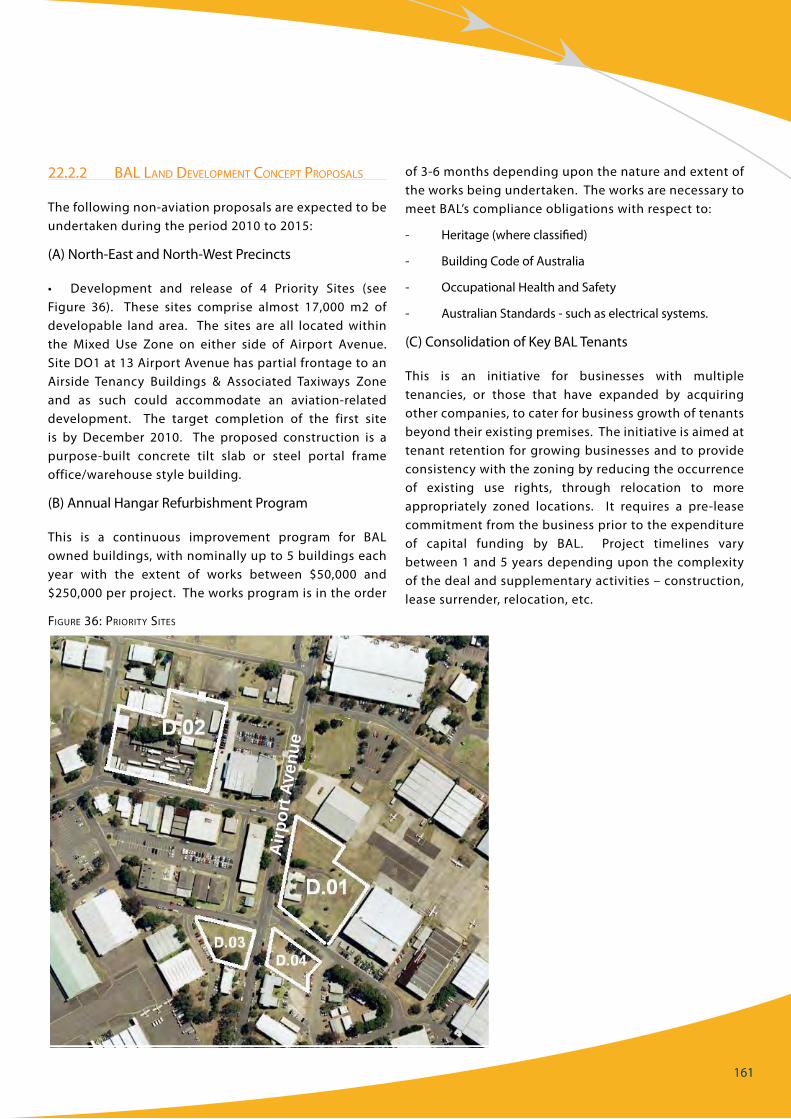
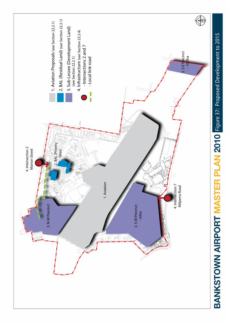
22.2.2 Bal land developMent concept proposals
The following non-aviation proposals are expected to be undertaken during the period 2010 to 2015:
(A) North-East and North-West Precincts
• Development and release of 4 Priority Sites (seefigure 36). These sites comprise almost 17,000 m2 of developable land area. The sites are all located within the Mixed Use Zone on either side of Airport Avenue. Site DO1 at 13 Airport Avenue has partial frontage to an Airside Tenancy Buildings & Associated Taxiways Zone and as such could accommodate an aviation-related development. The target completion of the first site is by December 2010. The proposed construction is a purpose-built concrete tilt slab or steel portal frame office/warehouse style building.
(B) Annual Hangar Refurbishment Program
This is a continuous improvement program for BAL owned buildings, with nominally up to 5 buildings each year with the extent of works between $50,000 and $250,000 per project. The works program is in the order
of 3-6 months depending upon the nature and extent of the works being undertaken. The works are necessary to meet BAL’s compliance obligations with respect to:
- Heritage (where classified)
- Building code of Australia
- Occupational Health and Safety
- Australian Standards - such as electrical systems.
(c) consolidation of Key BAL Tenants
This is an initiative for businesses with multiple tenancies, or those that have expanded by acquiring other companies, to cater for business growth of tenants beyond their existing premises. The initiative is aimed at tenant retention for growing businesses and to provide consistencywiththezoningbyreducingtheoccurrenceof existing use rights, through relocation to more appropriately zoned locations. It requires a pre-leasecommitment from the business prior to the expenditure of capital funding by BAL. Project timelines vary between 1 and 5 years depending upon the complexity of the deal and supplementary activities – construction, lease surrender, relocation, etc.
Airp
ort A
venu
e
Figure 36: priority sites
162
(D) Partnerships with Training Providers
The National Aviation Policy green Paper identifies future aviation industry skills and productivity as a key national initiative, including forming partnerships with training and educational providers. BAL has continued to support the aviation industry including flight training, education and promoting aviation as a career to young people.
In recent years the gA industry has enjoyed strong economic conditions in particular flight training which has enjoyed considerable growth. BAL has also promoted aviation education and has both the University of NSW and TAfE Padstow located on the Airport and is keen to develop a campus style facility to further enhance aviation education. BAL has also taken a leading position trying to attract young people to this industry. The Airport has hosted three successful Aviation careers Expos promoting the many career paths available in aviation. Working with local, national and international aviation companies, thousands of senior students have attended the Expos. They may have otherwise not been given the opportunity to get close to this industry.
22.2.3 suB-lessee or third party property developMent proposals
The following non-aviation proposals are expected to be undertaken during the period 2010 to 2015:
(A) North-West Precinct
Within this precinct, construction has commenced on a new supermarket and three speciality shops fronting Birdwood Road. Other potential developments include:
• warehouse/office
• commercial/retail
• medicalcentre.
(B) South-West Precinct
A Stage 1 earthworks platform and associated drainage works have been completed. This would be followed by Stage 2 earthworks and drainage, relocation of the
Aviation Museum to camden Airport and services and roadwork to provide a business park environment, with potential developments which include:
• bulkygoodsretail
• DFOtyperetail
• logisticsfacilities
• warehouse/office
• commercial/retail.
(c) South-East Precinct
Earthworks, drainage and roadworks for access to Milperra Road have been undertaken for development of the former trotting track site at the south-east boundary of the Airport, with site works for the first development, a warehouse/office having started. Potential developments include:
• bulkygoodsretail
• logisticsfacilities
• warehouse/office
• commercial/retail
• recyclingfacilities.
Proposals for the Environment protection zone areconsidered in Section 19 and in the Preliminary Draft Airport Environment Strategy.
22.2.4 inFrastructure provision
Surface traffic and utility infrastructure provision are as described in Sections 17 and 18. These developments would only be implemented on an as-needed basis and subject to market demands. Infrastructure provision would comprise reticulation of electricity, water and sewer to necessary sites, lead-in power and water and sewer network upgrades and amplifications.
Implementation priorities within the 2010-15 period are illustrated in figure 37.
PART c: ISSUES MANAgEMENT
676
436
SPEE
D
HUMP
CAR
PARK
CAR
PARK
PARKCA
R
GUARD RAIL
GUARD RAIL
454
436
423
430
6
124
689
470
466
495
460
447
46245
6
454
493A
454
622 49
3
501
608
617
618
613 49
4
660
654
677
611
3162
51
62
52
6258
59
38 3715
2961
45
333232
47
19
2050
4813
30
12
5655
441
3
244
353540
6
9 64
60 7734
545463
7
11
10
57
662
536579
683
635
131
455
452 44
2
441
453
84 458
62
422
491
411
438
487
121
120
135
408
461
497
402
499
401
427
498
414
104
410
15
479
468
465
459
431
473
457
480
503
400
330
412
481
488
485
464
486
492
490
467
463
489
484
508
505
506
606
630
515
444
619
630
641
650
631
610
644
604
601
626
628
624
502
612
597
614
640
507
657
661
655
600
658
603
621
616
675
685
670
109
107
534
111
545
112
628a
646
666
643
678 51
2
504
272
271
275
17
273
274
16
483
14
123
6766 8
299
276
118
114
661
625
seat
ssh
ed
CAR
WA
SH
OFFIC
EOFF
ICE
HANGAR
AIR
PORT
LIG
HT
ROO
M
1.8m cyclone mesh fence
TS GNAR OO W
MILP
ERRA
ROA
D
KLEMMSTREET
DROVER RD
AIRPORT
AVENUE
KESTREL PLACE
ALLIN
GHAM
ST
TOWER ROAD
MARS
HALL
ST
Acac
ia, 2m
5tru
nks,5
m2
shru
bs
smal
l, <2
m
Casa
uarin
as
10m
Ass
orte
d5m s
hrub
6m tr
ee
5m tr
ee
Vario
us to
3-4
m
Scat
tere
d E.
to 1
m
Som
e E.
to 1
m
Eric
afol
iaEric
afol
ia
Acac
ia
Eric
afol
iaSh
rubs
to 2
m
som
e E.
Calli
stem
onSm
all s
hrub
s to
2m Smal
l E.
E. to
4m
som
e de
ad
Scat
tere
d
PARK
ING
CAR
295 P
ROPO
SED
1. A
viat
ion
Prop
osal
s (s
ee S
ectio
n 22
.2.1
)
2. B
AL
(Res
idua
l Lan
d) (s
ee S
ectio
n 22
.2.1
)
3. S
ub-L
esse
e (D
evel
opm
ent L
and)
(see
Sec
tion
22.2
.1)
4. In
fras
truc
ture
(see
Sec
tion
22.2
.4)
-
Inte
rsec
tions
2 a
nd 7
-
Loc
al li
nk ro
ad
Figu
re 3
7: P
ropo
sed
Dev
elop
men
t to
2015
3. N
-W P
reci
nct
3. S
-W P
reci
nct
- 24h
a
1. A
viat
ion
2. B
AL
(Prio
rity
Site
s)
4. In
ters
ectio
n 2
Mar
ion
Stre
et
4. In
ters
ectio
n 7
Milp
erra
Roa
d3.
S-E
Pre
cinc
t- 1
0.5h
a
164
22.3 BEyOND 2015
for the timing of developments beyond the initial five year period there is less certainty when a specific demand, business case or compliance trigger will be reached. further, the Act provides for the final Master Plan to remain in force for five years. consequently, this Master Plan will again be reviewed and updated in 2015.
further development of a business park environment in the north-west and north-east precincts would be considered at that time.

165