Embed Size (px)
Citation preview

Page 1 of 59
WALL MOUNTED GAS/ELECTRICModels:
INSTALLATION INSTRUCTIONS
Bard Manufacturing Company, Inc. Bryan, Ohio 43506www.bardhvac.com
Manual No.: 2100-587CSupersedes: 2100-587BDate: 10-30-14
WG3S2-AWG4S2-AWG5S2-A
WG3S2-BWG4S2-BWG5S2-B
WG3S2-CWG4S2-CWG5S2-C
WARNINGREAD ALL INSTRUCTIONS CAREFULLY BEFORE BEGINNING THE INSTALLATION.
THE INSTALLATION MUST COMPLY WITH THESE INSTRUCTIONS AND THE REQUIREMENTS OF ALL GOVERNING CODES AND ORDINANCES FOR THE INSTALLATION LOCATION.
IT IS THE RESPONSIBILITY OF INSTALLER TO KNOW AND UNDERSTAND ALL OF THESE REQUIREMENTS.
FAILURE TO DO SO COULD CREATE A HAZARD RESULTING IN PROPERTY DAMAGE, BODILY INJURY, OR DEATH.

Manual 2100-587CPage 2 of 59
CONTENTS
Getting Other Information and Publications................4WG Series Model Nomenclature ................................5Ventilation Options......................................................5Air Conditioning Module Options ................................6 1. Important..............................................................9 2. Application ...........................................................9 3. Duct Work ............................................................9 4. High Altitude Applications ....................................9 5. Transportation Damage .....................................10 6. Installation..........................................................10 7. Wall Mounting ....................................................10 8. Mounting the Unit...............................................10 9. Clearances.........................................................16 10. Vent Terminal and Combustion Inlet Hood ........17 11. Optional Vertical Venting....................................1712. Vent Resizing Instructions .................................18 13. Fresh Air Intake..................................................18 14. Condensate Drain ..............................................18 15. Wiring – Main Power..........................................19 16. Wiring – Low Voltage Wiring ..............................20 17. Thermostats .......................................................20 18. Gas Supply & Piping ..........................................26 19. Manifold Pressure Adjustment ...........................27 20. Checking Gas Input Rate...........................27 & 28
21. StandardOrificeSizing&High Altitude Derate ...................................................29 22. Conversion of Gas Input BTUH From High to Low Rating .....................................................31 23. Measuring Air Temperature Rise .......................31 24. Filters .................................................................32 25. Compressor Control Module ......................32 & 33 26. Lighting & Shutdown Instructions ......................34 27. Service Agency Procedures...............................35 28. Maintaining Unit in Good Working Order ....35 & 362 9. Replacement Parts .............................................36 30. Sequence of Operation – Heating .....................37 31. Sequence of Operation – Cooling .....................37 32. Indoor Blower Operation ....................................38
Start Up Application .........................................................40 Important Installer Note .....................................40 High & Low Pressure Switch .............................40 Three Phase Scroll Compressor........................41
Troubleshooting Compressor Solenoid ........................................42 Fan Blade Setting Dimensions ..........................42 Removal of Fan Shroud .....................................42 ECMTM Motors ....................................................43 ECMTM Motors ....................................................4433. Pressure Service Ports ......................................45 34. R-410A Refrigerant Charge ...............................4635. LowNOxBurnerAssembly"N"Suffix Models Only – U.S. Installations Only ...............46Index – Wiring Diagrams ..........................................47Wiring Diagrams ...............................................48 – 59
Page Page

Manual 2100-587CPage 3 of 59
CONTENTS
FIGURES Figure 1 Unit Dimensions ...................................... 8 Figure 2A Mounting Instructions – WG3S2 ............ 11 Figure 2B Mounting Instructions–WG4S2 & WG5S2 .....12 Figure 3 Combustible Clearance ......................... 13 Figure 4 Wall Mounting Instructions .................... 14 Figure 5 Wall Mounting Instructions .................... 14 Figure 6 Common Wall Mounting Installations .... 15 Figure 7 Location of Vent Terminal in Shipping ... 16 Figure 8 Vent Terminal & Combustion Air Intake ............................................... 17 Figure 9 Installation of Flexible Conduit .............. 20 Figure 10A Low Voltage Wiring - No Vent ................ 21 Figure 10B Low Voltage Wiring - CRV .................... 22 Figure 10C Low Voltage Wiring - Economizer ........ 23 Figure 10D Low Voltage Wiring - ERV .................... 24 Figure 11 Gas Pipe Connection ............................ 25 Figure 12 Proper Piping Practice ........................... 26 Figure 13 Access Internal Filter ............................. 32 Figure 14 Lighting & Shutdown Instruction Label ... 34 Figure 15 Top View of Gas Control ........................ 35 Figure 16 Sequence of Operation – Electronic Blower Control ....................................... 37 Figure 17 Furnace Control Board & Blower Control ....................................... 38 Figure 18 Fan Blade .............................................. 42 Figure 19 Control Disassembly ............................. 44 Figure 20 Winding Test .......................................... 44 Figure 21 Drip Loop ............................................... 44 Figure 22 Low NOx Insert ...................................... 46
TABLES Table1 Specifications ............................................7 Table 2 Minimum Installation Clearances ............16 Table 3 Thermostat Wire Size ..............................20 Table 4 Wall Thermostat ......................................20 Table 5 Length of Standard Pipe Threads ...........26 Table 6 Gas Pipe Sizes – Natural Gas .................26 Table 7 Natural Gas Derate Capacities For All Models ..........................................29 Table8 NaturalGasOrificeTables–WG3,4,5S ...30 Table8A NaturalGasOrificeTables ......................30 Table 9 Indoor Blower Performance .....................38 Table 10 Integrated Furnace & Blower Control Operation ....................................39 Table 11 Fan Blade Dimensions ............................42 Table 12 Cooling Pressures ...................................45
Page Page

Manual 2100-587CPage 4 of 59
Getting Other Information and Publications
FOR MORE INFORMATION, CONTACT THESE PUBLISHERS:
ACCA Air Conditioning Contractors of America 1712 New Hampshire Avenue, NW Washington, DC 20009 Telephone: (202) 483-9370
ANSI American National Standards Institute 11 West Street, 13th Floor New York, NY 10036 Telephone: (212) 642-4900 Fax: (212) 302-1286
ASHRAE American Society of Heating Refrigerating, and Air Conditioning Engineers, Inc. 1791 Tullie Circle, NE. Atlanta, GA 30329-2305 Telephone: (404) 636-8400 Fax: (404) 321-5478
NFPA National Fire Protection Association Batterymarch Park P.O. Box 9101 Quincy, MA 02269-9901 Telephone: (800) 344-3555 Fax: (617) 984-7057
CSA Canadian Standards Association 178 Rexdale Boulevard Rexdale, Ontario Canada. M9W 1R3 Telephone: (416) 447-4044
BARD MANUFACTURING COMPANY, INC.BRYAN, OHIO 43506 USA
These publications can help you install the furnace. You can usually find these at your local library or purchase them directly from the publisher. Be sure to consult current edition of each standard.
National Fuel Gas Code .......... ANSI Z223.1 / NFPA 54
National Electrical Code ......................ANSI / NFPA 70
Standard for the Installation ............. ANSI / NFPA 90Aof Air Conditioning and Ventilating Systems
Standard for Warm Air ..................... ANSI / NFPA 90BHeating and Air Conditioning Systems
Standard for Chimneys, ................................ NFPA 211Fireplaces, Vents, and Solid Fuel Burning Appliances
Load Calculation for ........................... ACCA Manual JResidential Winter and Summer Air Conditioning
Duct Design for Residential ..............ACCA Manual DWinter and Winter Air Conditioning and Equipment Selection
Canadian Electrical Code ..............................CSA C22.1
Canadian Installation Code……………CAN/CGA B149

Manual 2100-587CPage 5 of 59
WG 4 S 2 – A X C X X X X X X
WALL MOUNT GAS/ELECTRIC GENERAL MODEL NUMBER NOMENCLATURE
Low ambient control is required with economizer for low temperature compressor operation.
VENTILATION OPTIONS
Description Factory Installed Code No.
Field InstalledPart No.
Blank-Off Plate B WGSBOP-5
Commercial Ventilator – Multiple Position V WGSCRVMP-5
Economizer - Fully Modulating E WGSEIFM-5
Energy Recovery Ventilator – 230 Volt R WGSERV-A5A
Energy Recovery Ventilator – 460 Volt R WGSERV-C5A
MODELWall MountGas/Electric
CONTROL OPTIONS(See Table page 6)
VENT(See Table Below)
COOLINGCAPACITY3 = 3 ton4 = 4 ton5 = 5 ton
OUTLETX = Front (Standard)T = Top
COIL OPTIONSX = Standard1 = Phenolic coated evaporator2 = Phenolic coated condenser3 = Phenolic coated both coils
COLORX = Beige (Standard)4 = Buckeye Gray
FILTERX = 2” Pleated (Standard)W = 1” Washable
VOLTAGEA = 230/208-60-1B = 230/208-60-3C = 460-60-3
REVISION
FEATURE(-) = Standard(C) = Canada
EMISSIONSX = StandardN=NOxCertified
*125,000BTUinputmodelisnotNOxcertified.
HEATING INPUT A = 50,000 B = 75,000 C = 100,000 D = 125,000*
Denotes StepCapacity

Manual 2100-587CPage 6 of 59
AIR CONDITIONING MODULE OPTIONS
STD = Standard equipment
CCM Compressor control module has adjustable 30 second to 5 minute delay-on-breaktimer. On initial power up, or any time the power is interrupted, the delay-on-make will be 2 minutes plus 10% of the delay-on-break setting. There is no delay-on-make during routine operation of the unit. The module also provides the lockout feature (with 1 retry) for high and/or low pressure controls, and a 2 minute timed bypass for low pressure control.
HPC High pressure control is auto reset. Always used with compressor control module (CCM) which is included. See note .
LPC Low pressure control is auto reset. Always used with compressor control module (CCM) which is included. See note .
LAC Low ambient control permits cooling operation down to 0°F.
CAUTIONDuringtheinitialfiringoftheburnerstherewillprobablybesomeamountofsmokeissuedtothecirculating air stream as the result of residual oil burning off of the heat exchanger tubes. This oil is required during the forming process of the stainless steel heat exchanger tubes to facilitate the bending. OSHA or the National Toxicology Program does not list the oil as a carcinogen. In vapor form this may be irritating to the eyes or could cause headaches. This is a one-time occurrence, and ventilation of the space may be required depending upon the space being conditioned.
CCM
HPC
LPC
LAC
Factory Installed Code
Field Installed Part
STD STD STD X N/A
STD STD STD -- H CMA-28

Manual 2100-587CPage 7 of 59
* 75
° C
Cop
per w
ire s
ize
** M
axim
um ti
me
dela
y fu
se o
r circ
uit b
reak
er
TAB
LE 1
SPEC
IFIC
ATIO
NS
Mod
els
WG
3S2-
AW
G3S
2-B
WG
3S2-
CW
G4S
2-A
WG
4S2-
BW
G4S
2-C
WG
5S2-
AW
G5S
2-B
WG
5S2-
C
Ele
ctric
al R
atin
g - 6
0 H
z23
0/20
8-60
-123
0/20
8-60
-346
0-60
-323
0/20
8-60
-123
0/20
8-60
-346
0-60
-323
0/20
8-60
-123
0/20
8-60
-346
0-60
-3
Ope
ratin
g Vo
ltage
Ran
ge19
7-25
318
7-25
341
4-50
619
7-25
318
7-25
341
4-50
619
7-25
318
7-25
341
4-50
6
Min
imum
Circ
uit A
mpa
city
2723
1236
2714
4531
15
* Fi
eld
Wire
Siz
e8
1014
810
128
812
Gro
und
Wire
Siz
e10
1014
1010
1210
1012
** D
elay
Fus
e - M
ax.
4030
1545
4020
6045
20
Com
pres
sor
Com
pres
sor T
ype
Scr
oll
Scr
oll
Scr
oll
Scr
oll
Scr
oll
Scr
oll
Scr
oll
Scr
oll
Scr
oll
Volts
230/
208
230/
208
460
230/
208
230/
208
460
230/
208
230/
208
460
Rat
ed L
oad
Am
ps11
.6 /
12.9
8.8
/ 9.9
6.7
15.0
/ 17
.810
.4 /
11.8
5.4
20.9
/ 23
.012
.8 /
14.1
6.2
Bra
nch
Circ
uit S
elec
tion
Cur
rent
15.3
11.7
5.8
21.2
14.1
6.5
27.2
16.5
7.2
Lock
Rot
or A
mps
8373
3810
483
4115
311
052
Fan
Mot
or a
nd C
ompr
esso
r
Fan
Mot
or -
HP
/RP
M/S
PD
1/3-
850-
21/
3-85
0-2
1/3-
850-
11/
3-85
0-2
1/3-
850-
21/
3-85
0-1
1/3-
850-
21/
3-85
0-2
1/3-
850-
1
Blo
wer
Mot
or -
Am
ps2.
52.
51.
32.
52.
51.
32.
52.
51.
3
Fan
- DIA
/CFM
24" –
270
024
" – 2
700
24" –
270
024
" – 2
700
24" –
270
024
" – 2
700
24" –
270
024
" – 2
700
24" –
270
0
Mot
or a
nd E
vapo
rato
r
Blo
wer
Mot
or -
HP
/RP
M/S
PD
1/2
Varia
ble
1/2
Varia
ble
1/2
Varia
ble
3/4
Varia
ble
3/4
Varia
ble
3/4
Varia
ble
3/4
Varia
ble
3/4
Varia
ble
3/4
Varia
ble
Blo
wer
Mot
or -
Am
ps3.
63.
63.
64.
74.
74.
76.
06.
06.
0
CFM
Coo
ling
& E
.S.P
.11
0011
0011
0015
0015
0015
0017
0017
0017
00
Filte
r Siz
es (I
nche
s)20
x 3
0 x
220
x 3
0 x
220
x 3
0 x
220
x 3
0 x
220
x 3
0 x
220
x 3
0 x
220
x 3
0 x
220
x 3
0 x
220
x 3
0 x
2
Cha
rge
(R-4
10A
)15
615
615
624
024
024
024
624
624
6

Manual 2100-587CPage 8 of 59
M
G
N
P
D
AFF GG HH
Y
Z
T
C KJ
BB
DD
RW
S S S S
CC
F
B
AAX
U
I
V
S
BEE
OE
L
II Q
HFIL
TER
SERV
ICE
DOOR
GAS
PANE
LVE
NTOP
TION
CIRC
UIT
BREA
KER/
FRON
T
RETU
RNOP
ENIN
G
COND
ENSE
R
BACK
SUPP
LYOP
ENIN
G
DISC
ONNE
CT A
CCES
S
RIGH
T SI
DE
LOW
VOL
TAGE
PANE
L(LO
CKAB
LE)
PANE
LDOO
R
COMB
USTI
ONAI
REX
HAUS
T
AIR
INTA
KECO
MBUS
TION
ENTR
ANCE
S
VEST
IBUL
EDO
OR
AIR
INLE
TS
CONT
ROL
ENTR
ANCE
S
COND
ENSE
R
4DEG
.PIT
CHIN
TOP
AIR
OUTL
ET
HIGH
VOL
TAGE
ENTR
ANCE
S
FRON
TDO
OR
MIS-
3240
A
UNIT
AB
CD
EF
GH
IJ
KL
MN
OP
QR
WG3
S231
.63
87.5
33.3
828
.75
WG4
S2/W
G5S2
41.6
397
.543
.38
38.7
5
UNIT
ST
UV
WX
YZ
AABB
CCDD
EEFF
GGHH
IIW
G3S2
3.75
24.9
WG4
S2/W
G5S2
13.7
534
.93.
252.
75
2.5
14.8
830
14.1
215
.44
42.8
815
.31
2.25
3.88
4217
.34
8.44
4.5
12.1
910
40.2
5
43.8
1
0.44
3.75
169.88
29.8
815
.88
27.2
5
1.25
7.25
1.13
FIG
UR
E 1
UN
IT D
IMEN
SIO
NS

Manual 2100-587CPage 9 of 59
A one-inch clearance to combustible material for the first three feet of duct attached to the outlet air frame is required. See Wall Mounting Instructions and Figures 2, 2A, 3 and 3A for further details.
Ducts through the walls must be insulated and all joints taped or sealed to prevent air or moisture entering the wall cavity.
Some installations may not require any return air duct. A metallic return air grille is required with installations not requiring a return air duct. The spacing between louvers on the grille shall not be larger than 5/8 inch.
Any grille that meets with the 5/8 inch louver criteria may be used. It is recommended that Bard Return Air Grille or Return Filter Grille be installed when no return duct is used. Contact distributor or factory for ordering information. If using a return air filter grille, filters must be of sufficient size to allow a maximum velocity of 400 fpm.
NOTE: If no return air duct is used, applicable installation codes may limit this cabinet to installation only in a single story structure.
4. HIGH ALTITUDE APPLICATIONSRatings of gas utilization equipment are based on sea level operation and need not be changed for operation at elevations up to 6,000 feet. For operation at elevations above 6,000 feet and in the absence of specific recommendations from the local authority having jurisdiction, equipment ratings shall be reduced as specified in Section 21.
1. IMPORTANTThe equipment covered in this manual is to be installed by trained, experienced service and installation technicians. All duct work or portions thereof not in the conditioned space should be properly insulated in order to both conserve energy and prevent condensation or moisture damage.
2. APPLICATIONThis is a fan-assisted forced air gas furnace with electric air conditioning for outdoor installation. A fan-assisted furnace is equipped with an integral mechanical means to draw products of combustion through the combustion chamber and heat exchanger. The furnace installation must conform with local building codes and ordinances or, in their absence, with the National Fuel Gas Code ANSI Z223.1 or CAN/CGA-B149.1, latest edition, and the National Electrical Code ANSI/NFPA-7 or CSA C22.1, latest edition. It is the personal responsibility and obligation of the purchaser to contact a qualified installer to assure that installation is adequate and is in conformance with governing codes and ordinances.
3. DUCT WORKThe unit is designed for use with or without duct work. See Warning on Page 9. Flanges are provided for attaching the supply and return ducts. These instructions explain the recommended method to install the air cooled self-contained electric air conditioning and gas heating unit and the electrical wiring connections and gas piping to the unit. The refrigerant system is completely assembled and charged. All internal wiring is complete.
These instructions and any instructions packaged with any separate equipment required to make up the entire heating/cooling system should be carefully read before beginning the installation. Note particularly “Starting Procedure” and any tags and/or labels attached to the equipment.
All duct work, supply and return, must be properly sized for the design airflow requirement of the equipment. Air Conditioning Contractors of America (ACCA) is an excellent guide to proper sizing.
Refer to Table 9 in this Manual for maximum static pressure available for duct design.
See Figure 3 and clearance information in Section 9 and Table 2 for additional information.
Design the duct work according to methods given by the Air Conditioning Contractors of America (ACCA). When duct runs through unheated spaces, it should be insulated with a minimum of one-inch of insulation. Use insulation with a vapor barrier on the outside of the insulation. Flexible joints should be used to connect the duct work to the equipment in order to keep the noise transmission to a minimum.
WARNINGIn all cases, there must be a metal duct connectionmadetothesupplyairflange,anda one inch clearance to combustibles must be maintained to this duct connection.For free blow applications, a metal sleeve must be used in the wall opening itself, again maintaining a one inch clearance to combustibles.Failuretousethesheetmetalcancausefireresulting in property damage, injury, or death.

Manual 2100-587CPage 10 of 59
5. TRANSPORTATION DAMAGEAll units are packed securely in shipping container. All units should be carefully inspected upon arrival for damage. In the event of damage, the consignee should:
1. Note on delivery receipt of any damage to container.
2. Notify carrier promptly, and request an inspection.
3. In case of concealed damage, the carrier must be notified as soon as possible within 15 days after delivery.
4. Claims for any damage, apparent or concealed, should be filed with the carrier, using the following supporting documents:
A. Original Bill of Lading, certified copy, or indemnity bond.
B. Original paid freight bill of indemnity in lieu thereof.
C. Original invoice or certified copy thereof showing trade and other discounts or deductions.
D. Copy of the inspection report issued by carrier’s representative at the time damage is reported to carrier.
6. INSTALLATIONSize of unit for proposed installation should be based on heat loss/heat gain calculations made according to methods of Air Conditioning Contractors of America (ACCA). The air duct should be installed in accordance with the Standards of the National Fire Protection Association for the Installation of Air Conditioning and Ventilating Systems of Other Than Residence Type, NFPA No. 90A, and Residence Type Warm Air Heating and Air Conditioning Systems, NFPA No. 90B. Where local regulations are at a variance with instructions, installer should adhere to local codes.
7. WALL MOUNTING INFORMATION 1. Two holes for the supply and return air
openings must be cut through the wall as detailed in Figure 4.
2. On wood-frame walls, the wall construction must be strong and rigid enough to carry the weight of the unit without transmitting any unit vibration.
3. Concrete block walls must be thoroughly inspected to insure that they are capable of carrying the weight of the installed unit.
2. The WG3S2, WG4S2 and WG5S2 models are suitable for 0 inch clearance on the installation mounting wall and to the top. For all models the supply air duct flange and the first 3 feet of supply air duct require a minimum of 1-inch clearance to combustible material.
3. Locate and mark lag bolt locations and bottom mounting bracket location.
4. Mount bottom mounting bracket.
5. Hook top rain flashing under back bend of top. Top rain flashing is shipped secured to the right side of the back.
6. Position unit in opening and secure with 5/16 lag bolts; use 7/8 inch diameter flat washers on the lag bolts. Use lag bolts long enough to support the unit’s weight when mounted to the structure. This length may be dependant on the type of construction.
7. Secure rain flashing to wall and caulk across entire length of top. See Figure 3.
8. On side-by-side installations, maintain a minimum of 20 inches clearance on right side to allow access to control panel and burner compartment, and to allow proper airflow to the outdoor coil. Additional clearance may be required to meet local or national codes.
8. MOUNTING THE UNIT 1. These units are secured by wall mounting
brackets which secure the unit to the outside wall surface at both sides. A bottom mounting bracket is provided for ease of installation but is not required.
CAUTIONIf the bottom bracket is used, be certain the bracket is secured to the outside wall surface inawaysufficienttosupporttheentireweight of the unit during installation until side mounting brackets are secured.
WARNINGFailure to provide the one inch clearance between the supply duct and a combustible surfaceforthefirstthreefeetofductcanresultinfirecausingdamage,injuryordeath.

Manual 2100-587CPage 11 of 59
FIG
UR
E 2
AM
OU
NTI
NG
INST
RU
CTI
ON
SFO
R W
G3S
2

Manual 2100-587CPage 12 of 59
FIG
UR
E 2
BM
OU
NTI
NG
INST
RU
CTI
ON
SFO
R W
G4S
2 A
ND
WG
5S2

Manual 2100-587CPage 13 of 59
FIGURE 3COMBUSTIBLE CLEARANCE
WARNINGA minimum of one (1) inch clearance must be maintained between the supply air duct and combustible materials. Thisisrequiredforthefirstthree(3)feetofducting.It is important to insure that the one (1) inch minimum spacing is maintained at all points.Failuretodothiscouldresultinoverheatingthecombustiblematerialandmayresultinafirecausingdamage,injuryor death.

Manual 2100-587CPage 14 of 59
FIGURE 4WALL MOUNTING INSTRUCTIONS
FIGURE 5WALL MOUNTING INSTRUCTIONS

Manual 2100-587CPage 15 of 59
FIGURE 6COMMON WALL MOUNTING INSTALLATIONS

Manual 2100-587CPage 16 of 59
9. CLEARANCESMinimum clearances, as specified in Table 2, must be maintained from adjacent structures to provide adequate fire protection, adequate combustion air, and room for service personnel.
While minimum clearances are acceptable for safety reasons, they may not allow adequate air circulation around the unit for proper operation in the cooling mode. Whenever possible, it is desirable to allow additional clearance, especially around the condenser inlet and discharge openings. DO NOT install the unit in a location that will permit discharged air from the condenser to recirculate to the condenser inlet.
TABLE 2MINIMUM INSTALLATION CLEARANCES
Outlet Duct(from combustible materials) 1inchfirst3feet
Vent Terminal(from combustible materials) * 17 inches
Condenser Inlet 20 inches
Top See Figure 3
Burner Service 20 inches
Combustible Base (Wood or Class A, B or C roof covering material) 0 inches
* See Figure 3
FIGURE 7LOCATION OF VENT TERMINAL IN SHIPPING
WARNINGClearances from combustible materials mustbemaintainedasspecified.Failuretomaintainclearancescouldcausefireresultingin property damage, injury, or death.

Manual 2100-587CPage 17 of 59
10. VENT TERMINAL AND COMBUSTION AIR INLET HOODThe vent terminal is shipped in the burner compartment. See Figure 7. Remove the two shipping screws and separate the two-piece assembly. Install the vent terminal by using the four screws provided. Make sure gasket is in place. See Figure 8. The combustion air intake hood is factory installed.
11. OPTIONAL VERTICAL VENTINGWith the optional vertical venting kit (VVK-5) this unit may be vented vertically through a roof or overhang. The kit includes a stainless steel transition drain tee, silicone sealant, and drain tubing.
If unit is installed with vertical vent kit, annually inspect the vent system and drain. Replace any portion of the vent system that shows signs of deterioration. Make sure drain is open and free of obstruction.
FIGURE 8VENT TERMINAL AND COMBUSTION AIR INTAKE
CAUTIONVent terminal must be installed as shown in Figure 8 for proper operation of the heating system.
NOTE: The inner vent hood gasket is designed to stretch over and seal around the combustion air blower outlet. This is a very critical seal to prevent water and flue products from entering the unit. Care must be taken to insure this gasket is in place and sealing properly.

Manual 2100-587CPage 18 of 59
12. VENT RESIZING INSTRUCTIONS
When an existing furnace is removed from a venting system servicing other appliances, the venting system is likely to be too large to properly vent the remaining attached appliances.
The following steps shall be followed with each of the appliances remaining connected to the common venting system, placed in operation one at a time while the other appliances remaining connected to the common venting system are not in operation.
1. Seal any unused openings in the venting system.
2. Inspect the venting system for proper size and horizontal pitch, as required in the National Fuel Gas code, ANSI Z223.1 or the CAN/CGA B149 Installation Codes and these instructions. Determine that there is no blockage or restriction, leakage, corrosion and other deficiencies which could cause an unsafe condition.
3. In so far as is practical, close all building doors and windows and all doors between the space in which the appliance(s) connected to the venting system are located and other spaces of the building. Turn on clothes dryers and any appliances not connected to the venting system. Turn on any exhaust fans, such as range hoods and bathroom exhausts, so they will operate at maximum speed. Do not operate a summer exhaust fan. Close fireplace dampers.
4. Follow the lighting instructions. Place the appliance being inspected in operation. Adjust thermostat so appliance shall operate continuously.
5. Test for draft hood equipped appliance spillage at the draft hood relief opening after 5 minutes of main burner operation. Use the flame of a match or candle.
6. After it has been determined that each appliance connected to the venting system properly vents when tested as outlined above, return doors, windows, exhaust fans, fireplace dampers and any other gas-burning appliances to their previous conditions of use.
7. If improper venting is observed during any of the above tests, the venting system must be corrected.
13. FRESH AIR INTAKEAll units are built with fresh air inlet slots punched in the service panel.
The default unit is built with blank-off plates installed. All capacity, efficiency and cost of operation information as required for Department of Energy “Energyguide” Fact Sheets is based upon the fresh air blank-off plate in place and is recommended for maximum energy efficiency.
One of several other ventilation options may be installed. Refer to model number and/or supplemental installation instructions.
14. CONDENSATE DRAINA plastic drain hose extends from the drain pan at the top of the unit down to the unit base. There are openings in the unit base for the drain hose to pass through. In the event the drain hose is connected to a drain system of some type, it must be an open or vented type system to assure proper drainage.

Manual 2100-587CPage 19 of 59
ELECTRICAL GROUNDING
When installed, the furnace must be electrically grounded in accordance with local codes or in the absence of local codes, with the National Electrical Code, ANSI/NFPA 70, or Canadian Electrical Code, CSA22.1, latest edition. Use a copper wire from green ground wire on the furnace to a grounded connection in the service panel or a properly driven and electrically grounded ground rod. See Table 1 for proper ground wire size.
FIELD INSTALLED EQUIPMENT
Wiring to be done in the field between the furnace and devices not attached to the furnace, or between separate devises which are field installed and located, shall conform with the temperature limitation for Type T wire {63 degrees F rise (36 degrees C)} when installed in accordance with the manufacturer’s instructions.
INSTALLATION OF FLEXIBLE CONDUIT THROUGH RETURN AIR OPENING
NOTE: To allow proper clearance between the control panel and any vent options, 90° conduit fittings must be used on the back of the control panel.
INSTALLING CONDUIT (See Figure 9.)
1. Remove conduit access panel if required to gain access to area behind control panel.
2. Remove low voltage and high voltage knockouts located in rear of control panel.
3. Run low voltage conduit through 7/8 bushing located in conduit entrance plate and secure to low voltage opening in rear of control panel.
4. Run high voltage conduit through 1-3/4 bushing located in conduit entrance plate and secure to high voltage opening in rear of control panel.
5. Replace conduit access panel if required to complete installation.
6. Seal around conduit in conduit entrance plate.
WARNINGFailure to provide a proper electrical ground couldresultinelectricshockorfire.
15. WIRING – MAIN POWER
Refer to unit rating plate for wire sizing information and maximum fuse or circuit breaker size. Each outdoor unit is marked with a “Minimum Circuit Ampacity”. This means that the field wiring used must be sized to carry that amount of current. All models are suitable only for connection with copper wire. Each unit and/or wiring diagram will be marked - “Use Copper Conductors Only”. These instructions must be adhered to. Refer to the National Electrical Code (NEC) for complete current carrying capacity data on the various insulation grades of wiring material. All wiring must conform to NEC and all local codes.
The electrical data lists fuse and wire sizes (75° C copper) for all models.
The unit rating plate lists a “Maximum Time Delay Relay Fuse” or circuit breaker that is to be used with the equipment. The correct size must be used for proper circuit protection and also to assure that there will be no nuisance tripping due to the momentary high starting current of the compressor motor.
The disconnect access door on this unit may be locked to prevent unauthorized access to the disconnect. To convert for the locking capability bend the tab located in the bottom left hand corner of the disconnect opening under the disconnect access panel straight out. This tab will now line up with the slot in the door. When shut, a padlock may be placed through the hole in the tab preventing entry.
See “Start Up” section for important information on three phase scroll compressor start ups.
WARNINGFor your personal safety, turn off electric power at service entrance panel before making any electrical connections. Failure to dosocouldresultinelectricshockorfire.
WARNINGFailure to provide an electrical power supply shut off means could result in electric shock orfire.

Manual 2100-587CPage 20 of 59
NOTE: The voltage should be measured at the field power connection point in the unit and while the unit is operating at full load (maximum amperage operating condition).
17. THERMOSTATS
16. WIRING – LOW VOLTAGE WIRINGLow Voltage ConnectionThese units use a 24-volt AC low voltage circuit. The “R” terminal is the hot terminal and the “C” terminal is grounded.“G” terminal is the fan input.“Y” terminal is the economizer input (where equipped).“Y1” terminal is the compressor input.“Y2” terminal is the compressor staging solenoid input.“R” terminal is 24 VAC hot.“C” terminal is 24 VAC grounded.“A” terminal is the ventilation input. This terminal energizes any factory or field installed vent option.“2” terminal is the alarm output.“W1” terminal is the gas heat input.
230/208 VOLT UNITS
All models are equipped with dual primary voltage transformers. All equipment leaves the factory wired on 240V tap. For 208V operation, reconnect from 240V to 208V tap. The acceptable operating voltage range for the 240V and 208V taps are:
460 VOLT UNITS
All models are equipped with single primary voltage transformers and no rewiring is required.
TABLE 3THERMOSTAT WIRE SIZE
FIGURE 9INSTALLATION OF FLEXIBLE CONDUIT
TABLE 4WALL THERMOSTAT
Direct Digital Controls (DDC)For total and proper control using DDC, a total of 5 controlled outputs are required (4 if no ventilation is installed).
LOW VOLTAGE CONNECTIONS FOR DDC CONTROL Fan Only Energize G Cooling Mode (Low) Energize G, Y1 Cooling Mode (High) Energize G, Y1, Y2 Heating Mode Energize W1 Ventilation Energize G, A
Thermostat Predominant Features
8403-058(TH5220D1151)
2 stage Cool; 2 stage HeatElectronic Non-ProgrammableAuto or Manual changeover
8403-060(1120-445)
3 stage Cool; 3 stage HeatProgrammable/Non-Programmable ElectronicHP or ConventionalAuto or Manual changeover
Tap Range
240 253 – 206208 220 – 187
Transformer VA FLA Wire
Gauge
Maximum Distancein Feet
50 2.1
20 gauge18 gauge16 gauge14 gauge12 gauge
4560
100160250

Manual 2100-587CPage 21 of 59
FIGURE 10ALOW VOLTAGE WIRING - NO VENT
G
Part #8403-058
Thermostat
Low Voltage Wiring - No Ventilation Package
1
O/B
Y
Thermostat
R
Unit Control Panel
Block
W2
RC W1 W2 E Y2 Y1 23
RC W Y2RCW2 Y G
LY1D/YO Y2AW1/EC G
Terminal
Part #8403-060
Thermostat Subbase
Factory Installed Jumper
Unit 24V
MIS-2330 D
A

Manual 2100-587CPage 22 of 59
FIGURE 10BLOW VOLTAGE WIRING - COMMERCIAL ROOM VENTILATOR
(MUST BE CONFIGUREDRE
D
MIS-2433 F
Low Voltage Wiring - Multi-position Commercial Room Ventilator
1GY
C
BLAC
K
INSTALL IF YOU REQUIRE VENTILATION ANYTIME BLOWER IS ON.
BlockRC W1 A W2 E Y2
PURPLE
23
RC W Y2RCW2 Y G
LY1D/YO Y2AW1/E
Y1
PINK
Terminal
Part #8403-058
R
Thermostat
Jumper
Thermostat Subbase
Factory Installed
Part #8403-060
BROW
N
O/BW2
Unit Control Panel
YELL
OW
PURP
LE
Thermostat G
1
Unit 24V
BLAC
K
WGSCRVMP-5WIRING PLUG
STEPCONTROLASSEMBLY
2
MUST INSTALL JUMPER FOR 8403-058 OR OTHER THERMOSTAT THAT DOES NOTHAVE OCCUPANCY OUTPUT.
FOR HEAT/COOL)
BLUE
ORAN
GE
1
2
F

Manual 2100-587CPage 23 of 59
FIGURE 10CLOW VOLTAGE WIRING - ECONOMIZER
W2
ORANGE
Thermostat
THERMISTOR
FROM
Low Voltage Wiring - EIFM ECONOMIZER
1
WGSEIFM-5
RED
O/BG
RED
Unit Control Panel
BlockRC W1 W2 E Y2 Y1 23
RC W Y2RCW2 Y G
LY1D/YO Y2A
PLUG
YUnit 24VTerminal
Part #8403-058
W1/EC R
Thermostat
Thermostat Subbase
G
Factory Installed Jumper
Part #8403-060
BLACK BLUE
PINKYELLOWPURPLE
WIRES
A
MIS-2432 C

Manual 2100-587CPage 24 of 59
FIGURE 10DLOW VOLTAGE WIRING - ENERGY RECOVERY VENTILATOR
MIS-2434 C
WGSERV-*5
R
HAVE OCCUPANCY OUTPUT.
Thermostat
Panel
Y
CONTROL
INSTALL IF YOU REQUIRE VENTILATION ANYTIME BLOWER IS ON.
BlockRC W1 A W2 E Y2 Y1 23
RC W Y2RCW2 Y G
LY1D/YO
Low Voltage Wiring - WGSERV-*5 Energy Recovery Ventilator
1G
Unit Control
Y2AW1/E W2
Terminal
C
WIRES
PLUG
G
Factory Installed Jumper
1
FROM
Part #8403-058
O/BPart #8403-060
2
Unit 24V
Thermostat Subbase
Thermostat
MUST INSTALL JUMPER FOR 8403-058 OR OTHER THERMOSTAT THAT DOES NOT
1
2
BLACK/WHITEBLUE
BROWN/WHITERED
ORANGE

Manual 2100-587CPage 25 of 59
FIGURE 11 GAS PIPE CONNECTION

Manual 2100-587CPage 26 of 59
18. GAS SUPPLY AND PIPING
GENERAL RECOMMENDATIONS
1. Be sure the gas line complies with the local codes and ordinances, or in their absence with the National Fuel Gas Code, ANSI Z223.1, or Natural Gas Installation Code, CAN/CGA B149.1, or Propane Installation Code B149.2, latest edition.
2. A sediment trap or drip leg must be installed in the supply line to the furnace.
3. A ground joint union shall be installed in the gas line adjacent to and upstream from the gas valve and downstream from the manual shut off valve.
4. An 1/8” NPT plugged tapping accessible for test gauge connection shall be installed immediately upstream of the gas supply connection to the furnace for the purpose of determining the supply gas pressure. This can be omitted if local codes permit use of plugged tapping in gas valve inlet.
5. Install listed manual shut off valve in the supply gas line external to and immediately upstream of the furnace. See Figure 11.
6. Use steel or wrought iron pipe and fittings.
7. DO NOT thread pipe too far. Valve distortion or malfunction may result from excess pipe within the control. Use pipe joint compound resistant to the action of liquefied petroleum gases on male threads only. DO NOT use Teflon tape. See Table 5 and Figure 12.
TABLE 5LENGTH OF STANDARD PIPE THREADS (INCHES)
TABLE 6GAS PIPE SIZES - NATURAL GAS
CHECKING THE GAS PIPINGBefore turning gas under pressure into piping, all openings from which gas can escape should be closed. Immediately after turning on gas, the system should be checked for leaks. This can be done by watching the 1/2 cubic foot test dial and allowing 4 minutes to show any movement, and by soaping each pipe connection and watching for bubbles. If a leak is found, make the necessary repairs immediately and repeat the above test. The furnace must be isolated from the gas supply piping system by closing the manual shut off valve on the combination gas control valve during pressure testing of the gas supply piping system at pressures up to 1/2 PSIG. The furnace and its individual shut off valve must be disconnected from supply piping and supply piping capped during any pressure testing of supply piping system at test pressures in excess of 1/2 PSIG.
Defective pipes or fittings should be replaced and not repaired. Never use a flame or fire in any form to locate gas leaks; use a soap solution.
After the piping and meter have been checked completely, purge the system of air. DO NOT bleed air inside the furnace. Be sure to check and relight all the gas pilots on other appliances that may have been extinguished because of interrupted gas supply.
FIGURE 12PROPER PIPING PRACTICE
8. Refer to Table 6 for Gas Pipe Sizes for natural gas. If more than one appliance is supplied from a single line size, capacity must equal or exceed the combined input to all appliances, and the branch lines feeding the individual appliances properly sized for each input.
Pipe SizeEffective Length of
Thread
Overall Length of Thread
3/8 1/2 9/16
3/4 1/2 - - 9/16 13/16
1 9/16 1
Length of Pipe -
Feet
Pipe Capacity - BTU per Hour Input Pipe Size
1/2" 3/4" 1" 1-1/4"10 132,000 278,000 520,000 1,050,000
20 92,000 190,000 350,000 730,000
30 73,000 152,000 285,000 590,000
40 63,000 130,000 245,000 500,000
50 56,000 115,000 215,000 440,000
60 50,000 105,000 195,000 400,000
70 46,000 96,000 180,000 370,000
80 43,000 90,000 170,000 350,000
100 38,000 79,000 150,000 305,000
THIS PRODUCT MUST BE GAS PIPED BY A LICENSED PLUMBER OR GAS
FITTER IN THE COMMONWEALTH OF MASSACHUSETTS.
MIS-897

Manual 2100-587CPage 27 of 59
19. MANIFOLD PRESSURE ADJUSTMENTA 0 to 15 inch water manometer with 0.1 inch resolution and a 1/8” NPT manual shut off valve is needed to measure actual manifold pressure.
Depending on your local gas heating value and elevation, you may need to adjust manifold pressure or change orifices to get proper gas input rate. Check with your local gas supplier to determine heating value (BTU/cu. ft.) of natural gas in your area.
NOTE: If furnace is being installed at an altitude of more than 6,000 feet above sea level, you must derate the furnace. See Section 21 “Standard Orifice Sizing and High Altitude Derate”.
20. CHECKING GAS INPUT RATEIt is the installer’s responsibility to see that the BTU input rate of the furnace is properly adjusted. Under-firing could cause inadequate heat, excessive condensation or ignition problems. Overfiring could cause sooting, flame impingement or overheating of heat exchanger.
1. Turn off gas at equipment shut off valve in gas supply line just ahead of furnace.
2. Remove plug from outlet pressure tap in gas control or gas manifold.
3. Install 1/8” NPT manual shut off valve in hole vacated by plug. Make sure shut off valve is in off position.
4. Attach manometer to 1/8” NPT manual shut off valve just installed.
PROPANE (LP) GAS CONVERSIONThis unit may be converted in the field for use with Propane (LP) gas. Propane gas conversion kit number WGCK-1 is designed for conversions of units installed from 0 – 6,000 feet elevations. Propane gas conversion kit number WGCK-2 is designed for conversions of units installed from 6,001 – 10,000 feet elevations. These kits may be purchased from your local distributor.
5. Slowly open equipment shut off valve in gas supply line just ahead of furnace. Start furnace following “Operating Instructions” on front door.
6. Slowly open 1/8” NPT manual shut off valve leading to manometer.
7. Read manifold pressure on manometer.
8. Adjust manifold pressure by turning gas control regulator adjusting screw clockwise to increase pressure or turning counterclockwise to decrease pressure. Manifold pressure must be within allowable range as follows:
• Natural gas manifold pressure must be between 3.2 and 3.8 inches W.C. Rated pressure is 3.5 inches.
• Propane gas (LP) manifold pressure must be between 9.7 and 10.3 inches W.C. Rated pressure is 10 inches.
NOTE: For natural gas, if gas flow rate can’t be properly set within these pressure ranges then you must change main burner orifices to obtain proper gas flow rate.
9. Shut off furnace. Turn off gas at equipment shut off valve in gas supply line just ahead of furnace. Install outlet pressure tap plug in gas control. Turn on gas.
10. Check regulator adjustment cover screw and gas control plug for gas leaks. Use a commercial soap solution made for leak detection.
WARNINGFailuretoadjustfurnacetotheproperfiringrate could cause heat exchanger failure.
WARNINGWhen converting from propane (LP) gas to naturalgas,thegasorificespudsandgasvalve spring must be replaced and the gas valve regulator pressure must be adjusted correctly.Failuretodosocanresultinfire,injury or death. Refer to Tables 8 and 8A for properorificesizing.
Natural gas spring kit, Part number 5603-007, can be purchased through your local distributor.
WARNINGCorrect manifold pressure is necessary for proper ignition and burner operation. Failure to accurately adjust pressure could cause heat exchanger failure.

Manual 2100-587CPage 28 of 59
NATURAL GAS INPUT RATE
Natural gas heating value (BTU/cu. ft.) can vary significantly. Before starting natural gas input check, obtain gas heating value at your location from local supplier. You will need a stopwatch to measure actual gas input.
1. Gas supply pressure must be between 5 and 7 inches W.C. for natural gas.
2. Turn off all other gas appliances. You may leave pilots on.
3. Start furnace following “Operating Instructions” on front door.
4. Let furnace warm up for 6 minutes.
5. Locate gas meter. Determine which dial has the least cubic feet of gas and how many cubic feet per revolution it represents. This is usually one-half, one or two cubic feet per revolution.
6. With stopwatch, measure time it takes to consume two cubic feet of gas.
• If dial is one-half cubic foot per revolution, measure time for four revolutions.
• If dial is one cubic foot per revolution, measure time for two revolutions.
• If dial is two cubic feet per revolution, measure time for one revolution.
7. Divide this time by two. This gives average time for one cubic foot of gas to flow through meter. Example: If it took 58 seconds for two cubic feet to flow, it would take 29 seconds for one cubic foot to flow.
8. Calculate gas input using this formula:
Gas Heating Value (BTU/cu. ft.) x 3,600 sec/hr Gas input = = BTU/hour Time (Seconds for one cubic foot of gas)
Example: Assume it took 29 seconds for one cubic foot of gas
to flow and heating value of 1,000 BTU/cu. ft.
1,000 x 3,600 Gas input = = 124,138 BTU 29
If you left no other pilots on, this is the furnace gas input.
PROPANE (LP) GAS INPUT RATE
1. Make sure you have proper main burner orifices.
2. Gas supply pressure must be between 11 and 13 inches W.C. for propane (LP) gas.
3. Start furnace following “Operating Instructions” on front door.
4. Let furnace warm up for 6 minutes.
5. Adjust manifold pressure to 10.0 W.C. ± 0.3 inches W.C. See Section 19, “Manifold Pressure Adjustment”.
WARNINGPropane (LP) gas installations do not have gas meters to double check input rate. Measure manifold pressure adjustment with an accurate manometer. Failure to accurately adjust pressure could cause heat exchanger failure,asphyxiation,fireorexplosion,resulting in damage, injury or death.
WARNINGDo not set Propane (LP) manifold pressure at 11.0 inches W.C. It could cause heat exchanger failure.
9. If you left water heater, dryer or range pilots on, allow for them in calculating correct furnace gas input. A quick way is to allow 1,000 BTU per hour for a water heater, 500 BTU per hour for dryer and 500 BTU per hour for each range burner pilot.
Example:
If you left gas water heater, dryer, two range burner pilots and one oven pilot on, allow:
Water heater pilot 1,000 BTU per hour Dryer pilot 500 BTU per hour 2 range burner pilots 1,000 BTU per hour 1 range oven pilot 500 BTU per hour 3,000 BTU per hour
Subtracting 3,000 BTU per hour from 124,138 BTU per hour measured above equals 121,138 BTU per hour. This would be the correct furnace gas input after allowing for pilots left on.
10. Manifold pressure may be adjusted within the range of 3.2 inches W.C. to 3.8 inches W.C. to get rated input ± 2 percent. See Section 19, “Manifold Pressure Adjustment”. If you cannot get rated input with manifold pressure within the allowable range, you must change orifices.

Manual 2100-587CPage 29 of 59
21. STANDARD ORIFICE SIZING AND HIGH ALTITUDE DERATE
This furnace is shipped with fixed gas orifices for use with Natural Gas and sized for 1000 BTU/cubic foot gas. Make sure actual gas input does not exceed rating plate input. The orifices may need to changed to get the correct gas input. Whether they need changed or not depends on input and the gas heat value at standard conditions and elevation. Consult the local gas supplier for gas heat value and any special derating requirements. See Section 20 for more information.
At higher altitudes, the density of the air is reduced. Therefore, for proper combustion, the quantity of
TABLE 7NATURAL GAS DERATE CAPACITIES
FOR ALL MODELS
gas burned in the furnace must also be reduced. This is called derating. This unit must be derated when installed at altitudes greater than 6,000 feet above sea level. A high altitude pressure switch must also be installed for operation above 6,000 feet. High altitude pressure switch kit number 8620-189 is designed for this application.
It is the installer’s responsibility to see that the furnace input rate is adjusted properly. Derating must be achieved by reducing the size of the main burner orifices. Derating the furnace by adjusting the manifold pressure lower than the range specified in the Section 19, “Manifold Pressure Adjustment” is considered to be an improper procedure.
WG Rated Input Sea Level 1000 2000 3000 4000 5000 6000
45,000 45,000 43,560 42,120 40,680 39,600 38,880 37,980
50,000 50,000 48,400 46,800 45,200 44,000 43,200 42,200
67,500 67,500 65,340 63,180 61,020 59,400 58,320 56,970
75,000 75,000 72,600 70,200 67,800 66,000 64,800 63,300
90,000 90,000 87,120 84,240 81,360 79,200 77,760 75,960
100,000 100,000 96,800 93,600 90,400 88,000 86,400 84,400
112,500 112,500 108,900 105,300 101,700 99,000 97,200 94,950
125,000 125,000 121,000 117,000 113,000 110,000 108,000 105,500

Manual 2100-587CPage 30 of 59
Allotherorificesizesshownareavailableasindividualitems.SeeOrificetablesbelowforpartnumbersandnumberrequired.
TABLE 8NATURAL GAS ORIFICE TABLES
Factory Standard Input
Gas Heat* ValueBTU/Cu. Ft.
Up to 6,000 Feet No Changes Except for BTU Content
6,001 to 8,000 Feet Requires Pressure Switch
ChangeandOrificeChange Based on BTU
Content
8,001 to 10,000 FeetRequires Pressure Switch
ChangeandOrificeChange Based on BTU
Content
25000 BTUPer Burner
700-749 2.90 2.80 2.70
750-799 2.80 2.70 2.60
800-849 2.70 2.60 2.50
850-899 2.60 2.50 2.45
900-949 2.50 2.45 (2.40)950-999 2.45 (2.40) 2.35
1000-1049** (2.40) 2.35 [2.30]1050-1100 [2.30] 2.25 2.20
Pressure Switch Standard (.55) Order 8620-189 High Altitude Pressure Switch Kit (.42)
(2.40) is the standard factory installed orifice size [2.30] orifices are shipped with the unit for field installed optional 10% derate
Optional10% Field Converted
Derate
Gas Heat* ValueBTU/Cu. Ft.
Up to 6,000 Feet No Changes Except for BTU Content
6,001 to 8,000 Feet Requires Pressure Switch
ChangeandOrificeChange Based on BTU
Content
8,001 to 10,000 FeetRequires Pressure Switch
ChangeandOrificeChange Based on BTU
Content
22500 BTUPer Burner
700-749 2.75 2.70 2.60
750-799 2.70 2.60 2.50
800-849 2.60 2.50
850-899 2.50 2.45 (2.40)900-949 (2.40) 2.35 [2.30]950-999 2.35 [2.30] 2.25
1000-1049** [2.30] 2.25 2.20
1050-1100 2.25 2.25 2.20
Pressure Switch Standard (.55) Order 8620-189 High Altitude Pressure Switch Kit (.42)
[2.30] orifices are shipped with the unit for field installed optional 10% input rate
(2.40) is the factory installed orifice size for full rated input
Atstandardconditions:30.00inchesMercury,60F,saturated,.60specificgravity.AllNaturalGasfactoryorificesizingandstandardinputratingsbasedonnominal1025BTU/cuftgasandsealevelconditions
***
Bard Part No. Orifice Size (mm) Orifice Diameter9010-092 2.10 0.08269010-088 2.15 0.08469010-087 2.20 0.08669010-086 2.25 0.08859010-082 2.30 0.09059010-085 2.35 0.09259010-079 2.40 0.09459010-084 2.45 0.09649010-093 2.50 0.09849010-094 2.60 0.10249010-095 2.70 0.10639010-096 2.75 0.10829010-097 2.80 0.11029010-098 2.90 0.1142
No. of Orifices Required Based on Unit Input Rating
45,000 (2)
50,000 (2)
68,000 (3)
75,000 (3)
90,000 (4)
100,000 (4)
113,000 (5)
125,000 (5)

Manual 2100-587CPage 31 of 59
23. MEASURING AIR TEMPERATURE RISEAir temperature rise (supply air temperature minus return air temperature) must be within allowable air temperature rise range specified on furnace rating plate and in Table 1.
You will need 2 thermometers with 1 degree resolution capable of reading up to 200 degrees F. Check thermometers to make sure they agree, or compensate accordingly.
Follow this procedure:
1. Open supply air registers and return air grilles. Make sure the registers and grilles are free of obstruction from rugs, carpets, drapes or furniture.
22. CONVERSION OF GAS INPUT BTUH FROM HIGH TO LOW RATINGAll the derated WG series units are produced with maximum BTUH input orifices installed. To field convert input, a change to main burner orifices is required.
NOTE: No change to air orifices is necessary. A set of low input orifices is shipped with every unit. They will be found packaged in a bag behind the burner door. Refer to the unit rating plate to confirm the proper orifice size. Proper installation of the orifices is detailed as follows:
A. Shut off electrical supply to the unit.
B. Shut off gas supply to the unit.
C. Remove burner access panel.
D. Disconnect gas valve from gas supply piping.
E. Disconnect the two wires from the gas valve.
F. Remove the manifold assembly so that orifices are now accessible and remove orifices.
G. Apply a modest amount of pipe compound to the new orifices and screw them into the manifold.
H. To assemble burner reverse steps A through G.
2. Set balancing dampers in supply duct system.
3. Check duct work for obstructions or leaks.
4. Make sure filters are clean and in place.
5. Place one thermometer in supply air plenum approximately 2 feet from furnace. Locate thermometer tip in center of plenum to insure proper temperature measurement.
6. Place second thermometer in return air duct approximately 2 feet from furnace. Locate thermometer tip in center of duct to insure proper temperature measurement.
7. Set room thermostat on highest temperature setting. Operate furnace 10 minutes. Record supply air and return air temperatures.
8. Calculate air temperature rise by subtracting return air temperature from supply air temperature.
• If air temperature rise is above the temperature rise range on rating plate, furnace is overfired or has insufficient airflow. Check gas input following the instructions in Section, “Checking Gas Input Rate”. If air temperature rise is still above temperature rise range specified, more heating airflow is needed. Check duct work and grilles to make sure all are properly sized.
• If air temperature rise is below the temperature rise range on rating plate, furnace is underfired or has too much airflow. Check gas input following the instructions in Section, “Checking Gas Input Rate”. If air temperature rise is still below temperature rise range specified, less heating airflow is needed. Adjust dampers or grilles as needed.
• After making adjustments, you must check air temperature rise to verify that resulting air temperature rise is within allowable range. If air temperature rise is still outside the temperature rise range specified on rating plate, check duct system design with a qualified heating engineer. It may be necessary to re-size the duct work. Recheck air temperature rise after revising duct systems.
9. Set room thermostat to desired setting.
10. Remove thermometers and seal duct work holes.
NOTE: Failure to seal holes could result in reduced system performance.
WARNINGFailure to follow these instructions could create a hazard resulting in property damage, bodily injury, or death.

Manual 2100-587CPage 32 of 59
24. FILTERSA 2” thick throwaway filter is supplied with each unit. This filter is installed by removing the filter access panel. (See Figure 13.)
Replacement filters are available through your dealer.
25. COMPRESSOR CONTROL MODULEThe compressor control module is standard on the models covered by this manual. The compressor control is an anti-short cycle/lockout timer with high and low pressure switch monitoring and alarm relay output.
Adjustable Delay On Make And Break TimerOn initial power up or anytime power is interrupted to the unit, the delay on make period begins, which will be 2 minutes plus 10% of the delay on break setting. When the delay on make is complete and the high pressure and low pressure switches are closed, the compressor contactor is energized. Upon shutdown, the delay or break timer starts and prevents restart until the delay on break and delay on make periods have expired.During routine operation of the unit with no power interruptions, the compressor will operate on demand with no delay.
HIGH PRESSURE SWITCH AND LOCKOUT SEQUENCE (Standard Feature)
If the high pressure switch opens, the compressor contactor will de-energize immediately. The lockout timer will go into a soft lockout and stay in soft lockout until the high pressure switch closes and the delay-on-make time has expired. If the high pressure switch opens again in this same operating cycle the unit will go into manual lockout condition and the alarm circuit will energize. Recycling the wall thermostat resets the manual lockout.
LOW PRESSURE SWITCH, BYPASS, AND LOCKOUT SEQUENCE
If the low pressure switch opens for more that 120 seconds, the compressor contactor will de-energize and go into a soft lockout. Regardless the state of the low pressure switch, the contactor will reenergize after the delay-on-make time delay has expired. If the low pressure switch remains open or opens again for longer than 120 seconds the unit will go into manual lockout condition and the alarm circuit will energize. Recycling the wall thermostat resets the manual lockout.
FIGURE 13ACCESS INTERNAL FILTER
MIS-3237
FILTER
FILTERSERVICEDOOR

Manual 2100-587CPage 33 of 59
ALARM OUTPUT
Alarm terminal is output connection for applications where alarm signal is desired. This terminal is powered whenever compressor is locked out due to HPC or LPC sequences as described.
NOTE: Both high and low pressure switch controls are inherently automatic reset devices. The high pressure switch and low pressure switch cut out and cut in settings are fixed by specific air conditioner or heat pump unit model. The lockout features, both soft and manual, are a function of the Compressor Control Module.
ADJUSTMENTS
ADJUSTABLE DELAY-ON-MAKE AND DELAY-ON-BREAK TIMER
The potentiometer is used to select Delay-on-Break time from 30 seconds to 5 minutes. Delay-on-Make (DOM) timing on power-up and after power interruptions is equal to 2 minutes plus 10% of Delay-on-Break (DOB) setting:
0.5 minute (30 seconds) DOB = 123 second DOM 1.0 minute (60 seconds) DOB = 126 second DOM 2.0 minute (120 seconds) DOB = 132 second DOM 3.0 minute (160 seconds) DOB = 138 second DOM 4.0 minute (240 seconds) DOB = 144 second DOM 5.0 minute (300 seconds) DOB = 150 second DOM
PHASE MONITORAll units with three phase scroll compressors are equipped with a three phase line monitor to prevent compressor damage due to phase reversal.
The phase monitor in this unit is equipped with two LEDs. If the “Y” signal is present at the phase monitor and phases are correct, the green LED will light.
If phases are reversed, the red fault LED will be lit and compressor operation is inhibited.
If a fault condition occurs, reverse two of the supply leads to the unit. Do not reverse any of the unit factory wires as damage may occur.
Optional Low Ambient ControlAn optional low ambient control is available for both factory and field installed options. The low ambient control is to be applied to the WG3S/WG4S/WG5S models when operation below 50° outdoor conditions are anticipated. Without this device, the evaporating pressure would fall off, and the indoor coil would ice over.The fan cycling control cycles the fan motor on, once the liquid refrigerant pressure reaches 350 psig, and off, once it has dropped to 225 psig. It will continue to cycle between these parameters depending on outdoor temperatures and the load/stage of the system.This cycling maintains a minimum liquid pressure affecting the minimum suction pressure. This effect insures an evaporating temperature that is slightly above the point of ice formation on the evaporator.

Manual 2100-587CPage 34 of 59
26. LIGHTING AND SHUTDOWN INSTRUCTIONS
FIGURE 14 INSTRUCTION LABEL BEND & PEEL “HERE” TO REMOVE LABEL LINER
A. This appliance does not have a pilot. It is equipped with an ignition device which automatically lights the burner. Do NOT try to light the burner by hand.
B. BEFORE OPERATING smell all around the appliance area for gas. Be sure to smell next to the floor because some gas is heavier than air and will settle on the floor.
WHAT TO DO IF YOU SMELL GAS
* Do not try to light any appliance.* Do not touch any electric switch; do not use any
phone in your building.* Immediately call your supplier from a neighbor’s
phone. Follow the gas supplier’s instructions.
* If you cannot reach your gas supplier; call the fire department.
C. Use only your hand to push in or move the gas control lever. Never use tools. If the lever will not push in or turn by hand, don’t try to repair it, call a qualified ser- vice technician. Force or attempted repair may result in a fire or explosion.
D. Do not use this appliance if any part has been under water. Immediately call a qualified service technician to inspect the appliance and to replace any part of the control sys- tem and any gas control which has been under water.
WARNING: If you do not follow these instructions exactly, a fire orexplosion may result causing property damage, personal injury or loss of life.
1. Set the thermostat to lowest setting.
2. Turn off all electric power to the appliance if service is to be performed.
3. Remove control access panel.
4. Push in gas control lever slightly and move to “OFF”. Do not force.
5. Replace control access panel.
7961-509
TO TURN OFF GAS TO APPLIANCE
FOR YOUR SAFETY READ BEFORE OPERATING
OPERATING INSTRUCTIONS1. STOP! Read the safety information above on this label.
2. Set the thermostat to lowest setting
3. Turn off all electric power to the appliance.
4. This appliance is equipped with an ignition device which automatically lights the burner. Do NOT try to light the burner by hand.
5. Remove control access panel.
6. Push in gas control knob slightly and turn clockwise to “OFF”.
NOTE: Knob cannot be turned to “OFF” unless knob is pushed in slightly. Do not force.
7. Wait five (5) minutes to clear out any gas. Then smell for gas, including near the floor. If you smell gas, STOP! Follow “B” in the safety information above on this label. If you don’t smell gas, go to the next step.
8. Turn gas control knob counterclockwise to “ON”.
9. Replace control access panel.
10. Turn on all electric power to the appliance.
11. Set thermostat to desired setting.
12. If the appliance will not operate, follow the instructions “To Turn Off Gas To Appliance” and call your service technician or gas supplier.
GAS CONTROLKNOB SHOWNIN “OFF” POSITION
GASINLET

Manual 2100-587CPage 35 of 59
27. SERVICE AGENCY PROCEDURES
MAIN BURNER
Observe the main burners in operation. The flame should be mostly “blue” with possibly a little orange (not yellow) at the tips of the flame. The flames should be in the center of the heat exchanger tubes and not impinging on the heat exchanger surfaces themselves.
Observe the fire until the blower starts (there is a normal delay period until the heat exchanger warms up). There should be no change in the size or shape of the flame. If there is any wavering or blowing of the flame on blower start-up, it is an indication of a possible leak in the heat exchanger.
28. MAINTAINING UNIT IN GOOD WORKING ORDER
The unit should be inspected annually by a qualified service agency.
BURNERS/HEAT EXCHANGER/FLUE GAS PASSAGE WAYS
The burners, heat exchanger and interior flue gas passages may be inspected using a light on small mirror or an extension handle. Remove the screws securing the inducer and collector box. Now inspect the upper tubes of the heat exchanger.
Check the exterior of the heat exchanger and the interior flue gas passages for any evidence of deterioration due to corrosion, cracking or other causes. If signs of sooting exist, remove the burners and clean the heat exchanger, as required.
FIGURE 15TOP VIEW OF GAS CONTROL
CAUTIONLabel all wires prior to disconnection when servicing controls. Wiring errors can cause improper and dangerous operation. Verify proper operation after servicing.
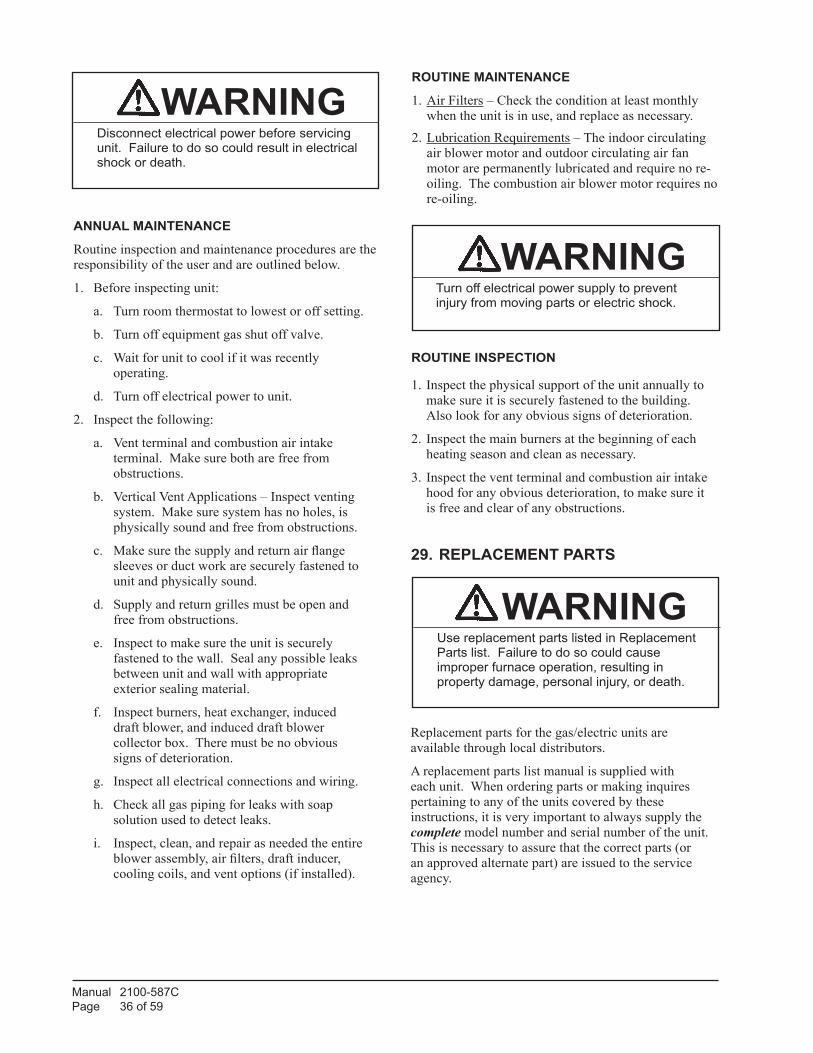
WARNINGFollow these procedures before inspecting furnace. • Turnroomthermostattoitslowestoroff setting. • Turnoffmanualgasshutoffvalve. • Waitatleast5minutesforfurnacetocool if it was recently operating. • Turnofffurnaceelectricalpower;failure to do so could result in injury or death.
WARNINGUse replacement parts listed in the Replacement Parts list only. The use of incorrect parts could cause improper unit operation, resulting in damage, injury or death.
MIS-165
Manual 2100-587CPage 36 of 59
ROUTINE MAINTENANCE
1. Air Filters – Check the condition at least monthly when the unit is in use, and replace as necessary.
2. Lubrication Requirements – The indoor circulating air blower motor and outdoor circulating air fan motor are permanently lubricated and require no re-oiling. The combustion air blower motor requires no re-oiling.
ROUTINE INSPECTION
1. Inspect the physical support of the unit annually to make sure it is securely fastened to the building. Also look for any obvious signs of deterioration.
2. Inspect the main burners at the beginning of each heating season and clean as necessary.
3. Inspect the vent terminal and combustion air intake hood for any obvious deterioration, to make sure it is free and clear of any obstructions.
29. REPLACEMENT PARTS
ANNUAL MAINTENANCE
Routine inspection and maintenance procedures are the responsibility of the user and are outlined below.
1. Before inspecting unit:
a. Turn room thermostat to lowest or off setting.
b. Turn off equipment gas shut off valve.
c. Wait for unit to cool if it was recently operating.
d. Turn off electrical power to unit.
2. Inspect the following:
a. Vent terminal and combustion air intake terminal. Make sure both are free from obstructions.
b. Vertical Vent Applications – Inspect venting system. Make sure system has no holes, is physically sound and free from obstructions.
c. Make sure the supply and return air flange sleeves or duct work are securely fastened to unit and physically sound.
d. Supply and return grilles must be open and free from obstructions.
e. Inspect to make sure the unit is securely fastened to the wall. Seal any possible leaks between unit and wall with appropriate exterior sealing material.
f. Inspect burners, heat exchanger, induced draft blower, and induced draft blower collector box. There must be no obvious signs of deterioration.
g. Inspect all electrical connections and wiring.
h. Check all gas piping for leaks with soap solution used to detect leaks.
i. Inspect, clean, and repair as needed the entire blower assembly, air filters, draft inducer, cooling coils, and vent options (if installed).
Replacement parts for the gas/electric units are available through local distributors.
A replacement parts list manual is supplied with each unit. When ordering parts or making inquires pertaining to any of the units covered by these instructions, it is very important to always supply the complete model number and serial number of the unit. This is necessary to assure that the correct parts (or an approved alternate part) are issued to the service agency.
WARNINGDisconnect electrical power before servicing unit. Failure to do so could result in electrical shock or death.
WARNINGTurn off electrical power supply to prevent injury from moving parts or electric shock.
WARNINGUse replacement parts listed in Replacement Parts list. Failure to do so could cause improper furnace operation, resulting in property damage, personal injury, or death.

Manual 2100-587CPage 37 of 59
30. SEQUENCE OF OPERATION – HEATINGOn a call for heat from the thermostat, the induced draft blower is energized. Once sufficient draft is established, the pressure switch contacts close and the ignition system is energized. The direct spark ignitor will be energized allowing gas to flow. At the same time the main valve is energized, a 30-second blower delay timer is activated.
After this delay, the heating speed blower relay energizes. The blower will begin operating and remain in operation until the set delay time after the call for heat has been satisfied. This timing sequence guarantees blower on, blower off operation.
This unit is equipped with a flame roll-out switch, which is wired in series with the control circuit. This is a manual reset switch and is used for the purpose of preventing possible fire hazard in the event of a system malfunction. If this switch has opened the control circuit, there could be a possible system malfunction. Some of the conditions that might cause a roll-out to occur are blockage or sooting of primary heat exchanger, overfiring of furnace due to improper main burner orifices or incorrect manifold pressure, insufficient combustion air, or installation deficiencies with respect to return air duct design or sizing.
Once the problem has been resolved, reset the switch by pressing down on the reset button on top of the switch. See Figure 16 for additional information.
31. SEQUENCE OF OPERATION – COOLINGNON-ECONOMIZERStage 1 (Y1) cooling call activates Step 1 (partial capacity, 66%) of compressor capacity.Stage 2 (Y2) cooling call activates Step 2 (full capacity, 100%) of compressor capacity.
WITH ECONOMIZERStage 1 (Y1) cooling call goes to economizer controls for decision: - If Enthalpy Control decides outdoor conditions are suitable for free cooling, the economizer will operate. • If Stage 2 cooling call is issued during economizer operation, the economizer will close and the compressor will go straight to Step 2 full capacity operation. - If Enthalpy Control decides outdoor conditions are not suitable for free cooling, the economizer will not operate (or close) and Step 1 of the compressor will operate. • If Stage 2 cooling call is issued, the compressor will shift to Step 2 full cooling capacity operation.
FIGURE 16SEQUENCE OF OPERATION
ELECTRONIC BLOWER CONTROL
Action System ResponseThermostat calls for heat(W terminal is energized).
•Combustionairblowerisenergized.•Airprovingswitchmakes.Airflowisestablished.•Ignitionsystemisenergized.•Gasvalveopensandmainburnerlights.•Heatfanondelaytimingbegins.Whentimingiscomplete,thecirculatingfanis
energized at heat speed.Thermostat ends call for heat. •Ignitionsystemisde-energizedandgasvalvecloses.
•Combustionairblowerisde-energizedafterpostpurgetiming.•Heatfanoffdelaytimingbegins.Whentimingiscomplete,thecirculatingfanis
de-energized.Thermostat begins call for cool(G and Y terminals re-energized).
•Coolingcontactorisenergized.•Circulatingfanisenergizedoncoolspeedaftercoolfanondelaytiming.
Thermostat begins call for fan(G terminal is de-energized).
•Circulatingfanisde-energized
Limit(flamerollout)opens. •Thermostatandignitionsystemarede-energizedandgasvalvecloses.•Combustionairblowerandcirculatingfanheatspeedareenergized.
Limit(autoreset)orflamerollout(manual reset) circuit closed.
•Combustionairblowerremainsenergizedforpostpurgetiming.•Thecirculationfanremainsenergizedfortheselecteddelayofftiming.•Normaloperationresumes.

Manual 2100-587CPage 38 of 59
32. INDOOR BLOWER OPERATIONThe indoor blower motor is a constant CFM variable speed direct drive motor. The motor is programmed to respond to individual thermostatic inputs that will determine the speed/airflow at which the motor operates. The motor software maintains the rated airflow across the range of allowable static whether the
TABLE 9INDOOR BLOWER PERFORMANCE
system is ducted or free blow. It will also maintain the temperature rise across the gas heat exchanger at the mid-point of the allowable rise range automatically. There are not adjustments that can be made in the field to adjust the airflows for any mode of operation.
FIGURE 17FURNACE CONTROL BOARD AND BLOWER CONTROL
Motor will deliver consistent CFM through voltage supply range with no deterioration (197-253V for 230/208V models, 414-506V for 460V models). Continuous CFM is the total air being circulated during continuous (manual) fan mode. Will occur automatically with a call for “Y1” signal from thermostat. Will occur automatically with a call for “Y2” signal from thermostat. Will occur automatically with a call for “W” signal from thermostat. Constant CFM of Variable Speed Motor should maintain mid-rise temperature differential through range of allowable static.
Model RatedESP
MaxESP
Continuous CFM
Rated 1st Stage Cooling CFM
Rated 2nd Stage Cooling CFM
Heating CFM
50,000 BTU Input
75,000 BTU Input
100,000 BTU Input
125,000 BTU Input
WG3S2 0.15 0.50 800 800 1100 1020 1250 1365 1410WG4S2 0.20 0.50 825 1100 1500 1020 1250 1365 1410WG5S2 0.20 0.50 850 1300 1700 1020 1250 1365 1410

Manual 2100-587CPage 39 of 59
TABLE 10INTEGRATED FURNACE AND BLOWER CONTROL OPERATION
IGNITION SEQUENCE CONTROLIgnition Source 24 VAC DSI
Flame Sensing Remote
Timings
- Prepurge- Postpurge- Inter-trial purge- Pressure switch proving period- Trials for ignition- Trial for ignition- Ignition sequence lockout
- Heat blower on - delay- Heat blower off - delay- Cool blower on - delay- Cool blower off - delay- Manual fan operations
- High limit control operation- Flame rollout switch operation
15 seconds30 seconds (0 if cycle terminated before valve “on”)15 seconds60 seconds3 per ignition sequence7secondstotaltimetoproveflame60 minutes (after 3 trials for ignition), auto reset- can be reset during the 60-minute lockout period by opening thermostat circuit for 3 seconds or more30 seconds (timing starts when ignitor cycles off)90, 120, 150 seconds selectable; factory set at 1207 seconds60 secondsOperates on selected heating speed and cycles off during ignition or burner start-up sequence.Automatic reset, ignition sequence restart. See Note 1.Manual reset, igniton sequence initiated after switch is manually reset. See Note 1.
NOTE 1: After the fourth limit trip on a given call for heat there will be a 1-hour delay before the ignition sequence will restart. After either high limit switch or flame rollout switch actuation the inducer will operate for the 30-second post purge and the comfort air blower will operate for the selected off delay. If on Manual Fan operation, the comfort air blower will continue to operate.
SAFETY UNITSHigh limit / RolloutPressure switch
SPST in 24 VoltSPST, safe start check
COMFORT FAN CONTROLHeating Speed FanNormal operation - ON delay- OFF delay
Limit Operation
Flame Sense
30secondsfixed.Timingstartswhenigniterde-energized.3 selectable timings -120 seconds standard can be changed to 90 or 150 seconds.ON when limit OPENOFF after OFF delay when limit CLOSESONifflameissensedand there is no call for heat.
Cooling Speed Fan- ON delay- OFF delay
7 seconds60 seconds
Manual Fan ON continuously on HEATING speed. When call for cool, the fan switches toCOOLINGspeed.Thenwhenthermostatsatisfied,thefanswitchesback to HEATING speed after COOLING OFF delay.
DIAGNOSTIC INDICATORA red LED is provided to indicate system faults as follows:
Steady ON - Control okay in standby, call for heat, cool or fan modesSteady OFF - Internal control fault or no power. Also check 3A fuse on control.1flash-Lockoutduetofailedignitionorflamedropouts2flashes-Pressureswitchopenwithinduceron3flashes-Pressureswitchisclosedwithinduceroff4flashes-Limitswitchisopen5flashes-Flamedetectedwithgasvalveclosed6flashes-Compressoroutputdelayedfromshortcycle/stagingtimerTheflashrateis0.25secondson,0.25secondsoffwith2.0secondspausebetweenflashcodes.Theflashrateis0.25seondson,0.25secondsoffwith2.0secondspausebetweenflashcodes.

Manual 2100-587CPage 40 of 59
START UPThese units require R-410A refrigerant & Polyol Ester oil.
APPLICATION:1. Use separate service and manufacturing equipment to avoid cross contamination of oil and refrigerants.2. Use recovery equipment rated for R-410A refrigerant.3. Use manifold gauges rated for R-410A (800 psi/ 250 psi low).4. R-410A is a binary blend of HFC-32 and HFC-125.5. R-410A is nearly azeotropic - similar to R-22 and R-12. Although nearly azeotropic, charge with liquid refrigerant.6. R-410A operates at 40-70% higher pressure than R-22, and systems designed for R-22 cannot withstand this higher pressure.7. R-410A has an ozone depletion potential of zero, but must be reclaimed due to its global warming potential.8. R-410A compressors use Polyol Ester oil.9. Polyol Ester oil is hygroscopic; it will rapidly absorb moisture and strongly hold this moisture in the oil.10. A liquid line dryer must be used - even a deep vacuum will not separate moisture from the oil.11. Limit atmospheric exposure to 15 minutes - MAXIMUM.12. If compressor removal is necessary, always plug compressor immediately after removal. Purge with small amount of nitrogen when inserting plugs.
IMPORTANT INSTALLER NOTEFor improved start-up performance, wash the indoor coil with a dishwasher detergent.
HIGH & LOW PRESSURE SWITCHAll models covered by this Manual are supplied with a remote reset high pressure switch and low pressure switch. If tripped, this pressure switch may be reset by turning the thermostat off then back on again.

Manual 2100-587CPage 41 of 59
THREE PHASE SCROLL COMPRESSOR START UP INFORMATIONScroll compressors, like several other types of compressors, will only compress in one rotational direction. Direction of rotation is not an issue with single phase compressors since they will always start and run in the proper direction.
However, three phase compressors will rotate in either direction depending upon phasing of the power. Since there is a 50-50 chance of connecting power in such a way as to cause rotation in the reverse direction, verification of proper rotation must be made. All three phase units incorporate a phase monitor to ensure proper field wiring. See the “Phase Monitor” section in this manual.
Verification of proper rotation must be made any time a compressor is change or rewired. If improper rotation is corrected at this time there will be no negative impact on the durability of the compressor. However, reverse operation for over one hour may have a negative impact on the bearing due to oil pump out.
NOTE: If compressor is allowed to run in reverse rotation for several minutes, the compressor’s internal protector will trip.
All three phase ZPS compressors are wired identically internally. As a result, once the correct phasing is determined for a specific system or installation, connecting properly phased power leads to the same Fusite terminal should maintain proper rotation direction.
Verification of proper rotation direction is made by observing that suction pressure drops and discharge pressure rises when the compressor is energized. Reverse rotation also results in an elevated sound level over that with correct rotations, as well as, substantially reduced current draw compared to tabulated values.
The direction of rotation of the compressor may be changed by reversing any two line connections to the unit.
See “Phase Monitor”, Page 33.

Manual 2100-587CPage 42 of 59
COMPRESSOR SOLENOID(See Sequence of Operation on Page 37 for function.) A nominal 24-volt direct current coil activates the internal compressor solenoid. The input control circuit voltage must be 18 to 28 volt ac. The coil power requirement is 20 VA. The external electrical connection is made with a molded plug assembly. This plug contains a full wave rectifier to supply direct current to the unloader coil.
Compressor Solenoid Test Procedure If it is suspected that the unloader is not working, the following methods may be used to verify operation.
1. Operate the system and measure compressor amperage. Cycle the compressor solenoid on and off at ten-second intervals. The compressor amperage should go up or down at least 25 percent.
2. If step one does not give the expected results, shut unit off. Apply 18 to 28 volt ac to the solenoid molded plug leads and listen for a click as the solenoid pulls in. Remove power and listen for another click as the solenoid returns to its original position.
3. If clicks can’t be heard, shut off power and remove the control circuit molded plug from the compressor and measure the solenoid coil resistance. The resistance should be 32 to 60 ohms depending on compressor temperature.
4. Next, check the molded plug.
Voltage check: Apply control voltage to the plug wires (18 to 28 volt ac). The measured dc voltage at the female connectors in the plug should be around 15 to 27 vdc.
Resistance check: Measure the resistance from the end of one molded plug lead to either of the two female connectors in the plug. One of the connectors should read close to zero ohms, while the other should read infinity. Repeat with other wire. The same female connector as before should read zero, while the other connector again reads infinity. Reverse polarity on the ohmmeter leads and repeat. The female connector that read infinity previously should now read close to zero ohms.
Replace plug if either of these test methods does not show the desired results.
Troubleshooting
FAN BLADE SETTING DIMENSIONSShown in the drawing below are the correct fan blade setting dimensions for proper air delivery across the outdoor coil. See Figure below.
Any service work requiring removal or adjustment in the fan and/or motor area will require that the dimensions below be checked and blade adjusted in or out on the motor shaft accordingly. See Table 11.
REMOVAL OF FAN SHROUD1. Disconnect all power to unit.2. Remove the screws holding both grills – one on
each side of unit – and remove grills.3. Remove screws holding fan shroud to condenser and
bottom – (9) screws.4. Unwire condenser fan motor.5. Slide complete motor, fan blade, and shroud
assembly out the left side of the unit.6. Service motor/fan as needed.7. Reverse steps to reinstall.
FIGURE 18FAN BLADE SETTING
"A"
AIRFLOW
MIS-1724
TABLE 11FAN BLADE DIMENSIONS
Model Dimension A
WG3S2WG4S2WG5S2
1.75"

Manual 2100-587CPage 43 of 59
Troubleshooting ECM™ MotorsCAUTION:Disconnect power from unit before removing or replacing connectors, or servicing motor. To avoid electric shock from the motor’s capacitors, disconnect power and wait at least 5 minutes before opening motor.Symptom Cause/ProcedureMotor rocks slightly • This is normal start-up for ECMwhen starting
Motor won’t start • Check blower turns by hand• No movement • Check power at motor • Check low voltage (24 Vac R to C) at motor • Check low voltage connections (G, Y, W, R, C) at motor • Check for unseated pins in connectors on motor harness • Test with a temporary jumper between R - G • Check motor for tight shaft • Perform motor/control replacement check • Perform Moisture Check
• Motor rocks, • Check for loose or compliant motor mount but won’t start • Make sure blower wheel is tight on shaft • Perform motor/control replacement check
Motor oscillates up • It is normal for motor to oscillate with no load & down while being on shafttested off of blower
Motor starts, butruns erratically• Varies up and down • Check line voltage for variation or “sag” or intermittent • Check low voltage connections (G, Y, W, R, C) at motor, unseated pins in motor harness connectors • Check “Bk” for erratic CFM command (in variable-speed applications) • Check out system controls, Thermostat • Perform Moisture Check
• “Hunts” or “puffs” at • Does removing panel or filter reduce high CFM (speed) “puffing”? - Reduce restriction - Reduce max airflow
• Stays at low CFM • Check low voltage (Thermostat) wires and despite system call connections for cool or heat CFM • Verify fan is not in delay mode; wait until delay complete • “R” missing/not connected at motor • Perform motor/control replacement check
• Stays at high CFM • “R” missing/not connected at motor • Is fan in delay mode? - wait until delay time complete • Perform motor/control replacement check
• Blower won’t shut off • Current leakage from controls into G, Y or W? Check for Triac switched thermostat or solid- state relay
Excessive noise • Determine if it’s air noise, cabinet, duct or motor noise; interview customer, if necessary• Air noise • High static creating high blower speed? - Is airflow set properly? - Does removing filter cause blower to slow down? Check filter - Use low-pressure drop filter - Check/correct duct restrictions
Symptom Cause/Procedure• Noisy blower or cabinet • Check for loose blower housing, panels, etc. • High static creating high blower speed? - Check for air whistling through seams in ducts, cabinets or panels - Check for cabinet/duct deformation
• “Hunts” or “puffs” at • Does removing panel or filter reduce high CFM (speed) “puffing”? - Reduce restriction - Reduce max. airflow
Evidence of Moisture• Motor failure or • Replace motor and Perform Moisture Check malfunction has occurred and moisture is present
• Evidence of moisture • Perform Moisture Check present inside air mover
Do Don’t• Check out motor, controls, • Automatically assume the motor is bad. wiring and connections thoroughly before replacing motor• Orient connectors down so • Locate connectors above 7 and 4 o’clock water can’t get in positions - Install “drip loops”• Use authorized motor and • Replace one motor or control model # with model #’s for replacement another (unless an authorized replacement)• Keep static pressure to a • Use high pressure drop filters some have ½” minimum: H20 drop! - Recommend high • Use restricted returns efficiency, low static filters - Recommend keeping filters clean. - Design ductwork for min. static, max. comfort - Look for and recommend ductwork improvement, where necessary
• Size the equipment wisely • Oversize system, then compensate with low airflow• Check orientation before • Plug in power connector backwards inserting motor connectors • Force plugs
Moisture Check• Connectors are oriented “down” (or as recommended by equipment manufacturer)• Arrange harness with “drip loop” under motor• Is condensate drain plugged?• Check for low airflow (too much latent capacity)• Check for undercharged condition• Check and plug leaks in return ducts, cabinet
Comfort Check• Check proper airflow settings• Low static pressure for lowest noise• Set low continuous-fan CFM• Use humidistat and 2-speed cooling units• Use zoning controls designed for ECM that regulate CFM• Thermostat in bad location?

Manual 2100-587CPage 44 of 59
Troubleshooting ECM™ Motors Cont’d.
Replacing ECM Control ModuleTo replace the control module for the GE variable-speed indoor blower motor you need to take the following steps: 1. You MUST have the correct replacement module. The controls are factory programmed for specific operating modes. Even though they look alike, different modules may have completely different functionality.USING THE WRONG CONTROL MODULE VOIDS ALL PRODUCT WARRANTIES AND MAY PRODUCE UNEXPECTED RESULTS. 2. Begin by removing AC power from the unit being serviced. DO NOT WORK ON THE MOTOR WITH AC POWER APPLIED. To avoid electric shock from the motor’s capacitors, disconnect power and wait at least 5 minutes before opening motor. 3. It is not necessary to remove the motor from the blower assembly, nor the blower assembly from the unit. Unplug the two cable connectors to the motor control assembly. There are latches on each connector. DO NOT PULL ON THE WIRES. The plugs remove easily when properly released. 4. Locate the screws that retain to the motor control bracket to the sheet metal of the unit and remove them. Remove two (2) nuts that retain the control to the bracket and then remove two (2) nuts that retain sheet metal motor control end plate. Refer to Figure 19. 5. Disconnect the three (3) wires interior of the motor control by using your thumb and forefinger squeezing the latch tab and the opposite side of the connector plug, gently pulling the connector. DO NOT PULL ON THE WIRES, GRIP THE PLUG ONLY. Refer to Figure 19. 6. The control module is now completely detached from the motor. Verify with a standard ohmmeter that the resistance from each motor lead (in the motor plug just removed) to the motor shell is >100K ohms. Refer to Figure 20. (Measure to unpainted motor end plate.) If any motor lead fails this test, do not proceed to install the control module. THE MOTOR IS DEFECTIVE AND MUST BE REPLACED. Installing the new control module will cause it to fail also. 7. Verify that the replacement control is correct for your application. Refer to the manufacturer’s authorized replacement list. USING THE WRONG CONTROL WILL RESULT IN IMPROPER OR NO
BLOWER OPERATION. Orient the control module so that the 3-wire motor plug can be inserted into the socket in the control. Carefully insert the plug and press it into the socket until it latches. A SLIGHT CLICK WILL BE HEARD WHEN PROPERLY INSERTED. 8. Reverse the steps #5, 4, 3 to reconnect the motor control to the motor wires, securing the motor control cover plate, mounting the control to the bracket, and mounting the motor control bracket back into the unit. MAKE SURE THE ORIENTATION YOU SELECT FOR REPLACING THE CONTROL ASSURES THE CONTROL’S CABLE CONNECTORS WILL BE LOCATED DOWNWARD IN THE APPLICATION SO THAT WATER CANNOT RUN DOWN THE CABLES AND INTO THE CONTROL. DO NOT OVERTIGHTEN THE BOLTS. 9. Plug the 16-pin control plug into the motor. The plug is keyed. Make sure the connector is properly seated and latched. 10. Plug the 5-pin power connector into the motor. Even though the plug is keyed, OBSERVE THE PROPER ORIENTATION. DO NOT FORCE THE CONNECTOR. It plugs in very easily when properly oriented. REVERSING THIS PLUG WILL CAUSE IMMEDIATE FAILURE OF THE CONTROL MODULE. 11. Final installation check. Make sure the motor is installed as follows: a. Motor connectors should be oriented between the 4 o’clock and 8 o’clock positions when the control is positioned in its final location and orientation. b. Add a drip loop to the cables so that water cannot enter the motor by draining down the cables. Refer to Figure 21.The installation is now complete. Reapply the AC power to the HVAC equipment and verify that the new motor control module is working properly. Follow the manufacturer’s procedures for disposition of the old control module.
Figure 19 Figure 20
Figure 21

Manual 2100-587CPage 45 of 59
33. PRESSURE SERVICE PORTS
High and low pressure service ports are installed on all units so that the system operating pressures can be observed. Table 12 outlines expected pressures at various indoor and outdoor temperatures.
Low side pressure ± 4 PSIGHigh side pressure ± 10 PSIG
TABLE 12 COOLING PRESSURE (ALL TEMPERATURES °F)
High Capacity Cooling Air Temperature Entering Outdoor Coil Degree F
Model Return Air Temperature Pressure 50 55 60 65 70 75 80 85 90 95 100 105 110 115
WG3S2
75° DB62° DB
Low SideHigh Side
112195
115214
119233
122253
126272
129291
131314
132337
134360
135383
136409
138435
139461
140487
80° DB67° DB
Low SideHigh Side
124201
127220
131239
134259
138278
139297
140319
140341
141363
141389
148413
149440
151468
152495
85° DB72° DB
Low SideHigh Side
135205
138224
142243
145263
149282
152301
154326
156350
157375
159399
161425
162451
164476
165502
WG4S2
75° DB62° DB
Low SideHigh Side
117197
119216
121235
123255
125274
127293
128316
130339
131361
132383
133410
135438
136466
137494
80° DB67° DB
Low SideHigh Side
127201
129220
131239
134259
136278
138298
138318
139341
139364
145381
145415
146443
146471
149500
85° DB72° DB
Low SideHigh Side
141203
143223
145243
148263
150283
152303
152326
153349
153372
154396
156422
158449
160478
162508
WG5S2
75° DB62° DB
Low SideHigh Side
118199
119217
120236
122260
123285
125309
126333
128357
129381
130405
132432
133460
135487
136514
80° DB67° DB
Low SideHigh Side
129205
130224
131247
131270
132292
132315
134339
137363
139387
143394
143438
145465
146492
148519
85° DB72° DB
Low SideHigh Side
137216
139237
140258
141279
142300
143321
146346
148370
151395
153419
155447
157474
158502
160529
Low Capacity Cooling Air Temperature Entering Outdoor Coil Degree F
Model Return Air Temperature Pressure 50 55 60 65 70 75 80 85 90 95 100 105 110 115
WG3S2
75° DB62° DB
Low SideHigh Side
126181
127198
129215
130233
132250
133267
135289
136310
138332
139353
141378
144404
146429
148454
80° DB67° DB
Low SideHigh Side
134184
134201
135218
135236
136253
136270
137291
137312
138333
138358
140380
142406
144432
146458
85° DB72° DB
Low SideHigh Side
153190
154207
155224
156241
157258
158275
160297
162318
163340
165361
167387
168413
170438
171464
WG4S2
75° DB62° DB
Low SideHigh Side
122184
124201
125218
127236
129254
131272
131291
132312
133335
134359
135381
137407
139435
141463
80° DB67° DB
Low SideHigh Side
132185
134203
136221
138239
140257
142275
145298
146317
147339
149354
149384
150410
151438
152467
85° DB72° DB
Low SideHigh Side
145187
147205
149223
152241
154259
156278
156397
157319
158343
159369
161390
163415
164443
165472
WG5S2
75° DB62° DB
Low SideHigh Side
123187
125207
127226
129245
131263
133282
134305
135328
136350
137373
139399
141425
143451
145477
80° DB67° DB
Low SideHigh Side
134192
136211
138230
139248
141267
143286
144308
145331
146353
148367
153402
155429
156456
158483
85° DB72° DB
Low SideHigh Side
146200
148217
149235
151252
152270
154287
156311
159335
161358
163382
165408
166434
168460
169486
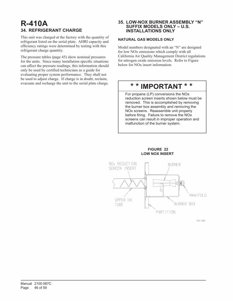
Manual 2100-587CPage 46 of 59
35. LOW-NOX BURNER ASSEMBLY “N” SUFFIX MODELS ONLY – U.S. INSTALLATIONS ONLY
NATURAL GAS MODELS ONLY
Model numbers designated with an “N” are designed for low NOx emissions which comply with all California Air Quality Management District regulations for nitrogen oxide emission levels. Refer to Figure below for NOx insert information.
* * IMPORTANT * * For propane (LP) conversions the NOx reduction screen inserts shown below must be removed. This is accomplished by removing the burner box assembly and removing the NOx screens. Reassemble unit properly beforefiring.FailuretoremovetheNOxscreens can result in improper operation and malfunction of the burner system.
FIGURE 22LOW NOX INSERT
R-410A34. REFRIGERANT CHARGEThis unit was charged at the factory with the quantity of refrigerant listed on the serial plate. AHRI capacity and efficiency ratings were determined by testing with this refrigerant charge quantity.
The pressure tables (page 45) show nominal pressures for the units. Since many installation specific situations can affect the pressure readings, this information should only be used by certified technicians as a guide for evaluating proper system performance. They shall not be used to adjust charge. If charge is in doubt, reclaim, evacuate and recharge the unit to the serial plate charge.

Manual 2100-587CPage 47 of 59
INDEX WIRING DIAGRAMS and LADDER DIAGRAMS
Model No. Heating Input Input Power Wiring Diagram Ladder Diagram
WG3S2
50,000
208/230/60/1
4085-154A 4085-15575,000 4085-156A 4085-157
100,000 4085-154A 4085-155125,000 4085-156A 4085-15750,000
208/230/60/3
4085-254A 4085-26975,000 4085-255A 4085-270
100,000 4085-254A 4085-269125,000 4085-255A 4085-27050,000
460/60/3
4085-377A 4085-39275,000 4085-378A 4085-393
100,000 4085-377A 4085-392125,000 4085-378A 4085-393
WG4S2
50,000
208/230/60/1
4085-154A 4085-15575,000 4085-156A 4085-157
100,000 4085-154A 4085-155125,000 4085-156A 4085-15750,000
208/230/60/3
4085-254A 4085-26975,000 4085-255A 4085-270
100,000 4085-254A 4085-269125,000 4085-255A 4085-27050,000
460/60/3
4085-377A 4085-39275,000 4085-378A 4085-393
100,000 4085-377A 4085-392125,000 4085-378A 4085-393
WG5S2
50,000
208/230/60/1
4085-154A 4085-15575,000 4085-156A 4085-157
100,000 4085-154A 4085-155125,000 4085-156A 4085-15750,000
208/230/60/3
4085-254A 4085-26975,000 4085-255A 4085-270
100,000 4085-254A 4085-269125,000 4085-255A 4085-27050,000
460/60/3
4085-377A 4085-39275,000 4085-378A 4085-393
100,000 4085-377A 4085-392125,000 4085-378A 4085-393

Manual 2100-587CPage 48 of 59
WG3S2-A, WG4S2-A, WG5S2-A 208/230/60/1
T2NC
CL2 L3
Aux.
L1
T1 T3
LPC
CCHP
C Y
ALR C
LPC
MINU
TES
4
235
R
1
SWITCHPRESSURE
HIGH
COMPRESSOR
Compressor
HIGH SPEED
MOTOR
CRANKCASE
16
REPLACED, IT MUST BE REPLACED WITH WIRING MATERIAL HAVING ATEMPERATURE RATING OF AT LEAST 105° C EXCEPT THE IGNITION CABLE
WHICH IS 250°C HIGH VOLTAGE CABLE
OUTDOORFAN
INTEGRATED FURNACE CONTROL 13
11
LOWVOLTAGE
STRIP
CIRCUIT
28
BREAKER21
MOVE RED WIRE TO208V TAP FOR 208V
OPERATION
TRANSFORMER18
GROUND TERMINAL
CAPACITOR19
LOWPRESSURE
SWITCH
INDUCED DRAFTBLOWER RELAY
MODULE
5
4
21
3
C
FAN
HERM
240V
208V
COM
R
CONTROL
23
HEATER
C
IF ANY ORIGINAL WIRE AS SUPPLIED WITH THE APPLIANCE MUST BE
50
WIRES CONNECTIF OPTIONNOT USED
32
A
62
INDUCEDDRAFT BLOWER
COMPRESSORCONTACTOR
51
GASVALVE
20
32 32
37
35
35
40
40
35
35
3232
32
32
32
32
34
32
62
28
2828
37
28
2727 42
43
41
38
36
47
41
47
28
2828
FLAME
LIMIT
SPARK IGNITOR
ROLLOUT
38
PRIMARY
FLAME SENSOR
39
PRESSURESWITCH
32
2835
38
44
57
51
51
4646
46
S
48
R
47
C
28
Bard Mfg. Co.Bryan, Ohio
4085-154 ALow VoltageHigh Voltage
Optional
32
Field
15
Factory
60
60
LOW AMBIENTCONTROL (OPT.)
33BL
ACK/
WHT
IE
SOLENOID
(OPT.)
BLAC
K
16 PIN PLUG FORINDOOR BLOWER
MOTOR
BLAC
K/W
HTIE
BLACK/WHITE
BLACK
SPEED 150
135
120
FUSE
FOR INDOORBLOWER MOTOR
132
610
13
1512
14
BLAC
K/W
HITE
PIN PLUG
208/230-60-1BL
ACK
BLAC
K
BLACK
P3
BLACK/WHITE
BROWN
1PL
12
BR
GRAY
BLACK/WHITE
BLACK
BROW
N
BLAC
K/W
HITE
BLACK
BLACK
BROWN
BLACK
BLACK/WHITE
27
USE COPPER CONDUCTORSSUITABLE FOR AT LEAST 75° C
TERM. BLOCK
GRAY
PINK
PINK
BLUE
BLUE
L1
L2
543
BLUE
GR
BLUE
BLUE
BLUE
1 2 34 5 6
8 971210 11
A
BLUE
A
PURPLE
PURPLE
PURPLE
C
MV
NO
MV
ORANGE
YELL
OW/R
ED
YELLOW
YELLOW
YELL
OW
YELLOW
YELLOW
BROW
N/W
HITE
YELLOW
WHITE
RED
RED
RED
RED/WHITE
RED/WHITE
RED
RED
RED
RED
REDRE
D
RED/
WHI
TE
RED32
RED/WHITE
RED
49 49
Wire Identification numbersfor Bard use only.99
32
32
RED/
RED
Model C. Breaker CapacitorWG3S2-A 40A 40+10/370WG4S2-A 45A 30+10/370WG5S2-A 60A 40+10/440

Manual 2100-587CPage 49 of 59
WG3S2-A, WG4S2-A, WG5S2-A 208/230/60/1
if Option Not
AWires Connect
Used 4085-155
Indoor Blower Motor14 12 10 6 2 13 3 116 Pin Plug for
15
W1
C
HEAT UNUSED
G
High VoltageOptional
Low Voltage
Factory
INDUCED DRAFT
A
Y2
ContactorCompressor
L2T2CS
R Compressor
Power Source
Line 2
230/208-60-1
BLOWER RELAY
Blower Motorfor Indoor
Block
4 3 5Ground
Ladder Diagram
A
Terminal
CapacitorDual Can
Motor
H
F
CT1L1
Line 1
Low
Volta
geTe
rm.B
lock
C NC
Outdoor Fan
Contactor Aux.Compressor
ContactorCompressor
BlockTerminal
BLOWER MOTOR24
INDUCED DRAFTBLOWER RELAYINDUCED DRAFT
CONTROL (OPT.)
R
CONTROL MODULECOMPRESSOR
CONTACTORCOMPRESSOR
LOW PRESSURE
CONTROL
LPC
LPC CALR
YHPC CCY1
2
R
FURNACE CONTROL BOARDK3 K4K4
K2 COOLD1
L1
LOW AMBIENT
Heater
HIGH PRESSURE
208
24VAC
240COMTransformer
Use for 208V Operation
BOARDCONTROLFURNACE
VALVEGAS
1
SWITCHPRESSURE
K1K1K4
K1K2
K3
1211368107954
2
LIMITPRIM.
ROLLOUTFLAMEW2
CONTROL
Crankcase
5 Pin Plug
HIGH SPEEDSOLENOID
L2L2 L2

Manual 2100-587CPage 50 of 59
WG3S2-A, WG4S2-A, WG5S2-A 208/230/60/1
T2NC
CL2 L3
Aux.
L1
T1 T3
32
A
62
INDUCEDDRAFT BLOWER
COMPRESSORCONTACTOR
51
GASVALVE
20
3232
37
35
35
40
40
3535
3232
32
32
32
32
34
32
62
28
2828
37
28
2727 42
43
41
38
36
47
41
33
2828
28
FLAME
LIMIT
SPARK IGNITOR
ROLLOUT
38
PRIMARY
FLAME SENSOR
39
PRESSURESWITCH
32
2835
38
44
57
51
51
4646
46
S
48
R
47
C
28
4085-156 ALow VoltageHigh Voltage
Optional
32
Field
15
Factory
60
60
LOW AMBIENTCONTROL (OPT.)
474
MIN
UTES
LPC
C
R
53 2
COMPRESSOR
Compressor
HIGH SPEED
MOTOR
LPC
CRANKCASE
16
REPLACED, IT MUST BE REPLACED WITH WIRING MATERIAL HAVING ATEMPERATURE RATING OF AT LEAST 105° C EXCEPT THE IGNITION CABLE
WHICH IS 250°C HIGH VOLTAGE CABLE
OUTDOORFAN
INTEGRATED FURNACE CONTROL 13
11
LOWVOLTAGE
STRIP
CIRCUIT
28
BREAKER21
MOVE RED WIRE TO208V TAP FOR 208V
OPERATION
TRANSFORMER18
GROUND TERMINAL
CAPACITOR19
LOWPRESSURE
SWITCH
INDUCED DRAFTBLOWER RELAY
MODULE
5
4
21
3
C
FAN
HERM
240V
208V
COM
R
CONTROL
23
HEATER
C
HIGHPRESSURE
SWITCH
NOT USED
CCHP
C Y
ALR
IF ANY ORIGINAL WIRE AS SUPPLIED WITH THE APPLIANCE MUST BE
50
WIRES CONNECTIF OPTION
1
PINK
PINK
BLUE
BLUE
L2
L1
543
BLUE
GR
BLUE
BLUE
BLUE
1 2 34 5 6
8 971210 11
A
A
BLUE
PURPLE
PURPLE
PURPLE
C
MV
NO
MV
ORANGEBR
OWN/
WHI
TE
YELLOW
YELLOW
YELL
OW
YELLOW
YELLOW
YELL
OW/R
ED
YELLOW
WHITE
RED
RED
RED
RED/WHITE
RED/WHITE
RED
RED
RED
RED
RED
RED
RED/
WHI
TE
RED32
RED/WHITE
RED
49 49
Wire Identification numbersfor Bard use only.99
32
32
RED/
RED
(OPT.)
SOLENOID
120
BLAC
K/W
HTIE
BLAC
K
16 PIN PLUG FORINDOOR BLOWER
MOTOR
BLAC
K/W
HTIE
BLACK/WHITE
BLACK
SPEED 150
135
FUSE
FOR INDOORBLOWER MOTOR
132
610
13
1512
14
BLAC
K/W
HITE
PIN PLUG
208/230-60-1BL
ACK
BLAC
K
BLACK
P3
BLACK/WHITE
BROWN
1PL
12
BR
GRAY
BLACK/WHITE
BLACK
BROW
N
BLAC
K/W
HITE
BLACK
BLACK
BROWN
BLACK
BLACK/WHITE
27
USE COPPER CONDUCTORSSUITABLE FOR AT LEAST 75° C
TERM. BLOCK
GRAY
Model C. Breaker CapacitorWG3S2-A 40A 40+10/370WG4S2-A 45A 30+10/370WG5S2-A 60A 40+10/440

Manual 2100-587CPage 51 of 59
WG3S2-A, WG4S2-A, WG5S2-A 208/230/60/1
if Option Not
AWires Connect
Used
Indoor Blower Motor14 12 10 6 2 13 3 116 Pin Plug for
15
W1
C
HEAT UNUSED
G
High VoltageOptional
Low Voltage
Factory
Compressor
A
RContactorCompressor
L2T2CS
Power Source
Blower Motorfor Indoor
Line 2
230/208-60-1
Y2
SOLENOID
Ground
Block
4 3 5
INDUCED DRAFT
Ladder Diagram
A
Terminal
CapacitorDual Can
Motor
H
F
CT1L1
Line 1
Low
Volta
geTe
rm.B
lock
C NC
Outdoor Fan
Contactor Aux.Compressor
ContactorCompressor
BlockTerminal
BLOWER MOTOR24
INDUCED DRAFTBLOWER RELAYINDUCED DRAFT
CONTROL (OPT.)
R
CONTROL MODULE COMPRESSOR
CONTACTORCOMPRESSOR
LOW PRESSURE
CONTROL
LPC
LPC CALR
YHPC CCY1
2
R
FURNACE CONTROL BOARDK3 K4K4
K2 COOLD1
L1
LOW AMBIENT
Heater
HIGH PRESSURE
208
24VAC
240COMTransformer
Use for 208V Operation
BOARDCONTROLFURNACE
VALVE GAS
1
SWITCHPRESSURE
K1K1K4
K1K2
K3
1211368107954
2
ROLLOUT FLAME
LIMITPRIM.W2
CONTROL
Crankcase
BLOWER RELAY
5 Pin Plug
HIGH SPEED
4085-157
L2L2 L2

Manual 2100-587CPage 52 of 59
WG3S2-B, WG4S2-B, WG5S2-B 208/230/60/3
T2NC
CL2 L3
Aux.
L1
T1 T3
PINK
PINK
5
BLUE
BLUE
543
GR
BLUE
BLUE
1 2 34
L3
68 97
1210 11
BLUEBLUE
L2
L1
BLUE
PURPLE
PURPLE
PURPLE
C
MV
NO
MV
YELLOW
ORANGE
YELLOW
YELLOW/BLACK
YELLOW
YELL
OW/B
LACK
BROW
N/W
HITE
YELL
OW/R
ED
YELLOW
YELLOW
YELLOW
YELLOW
YELLOW
YELLOW
RED
RED
RED
RED
RED
RED/
WHI
TE
RED/WHITE
RED
RED
RED
REDRE
D
RED/
WHI
TE
RED/WHITE
43
WHITERED/
RED
49 49
45
53
RED
3130
29
47
RED
120
BLACK
BLACK
NOT USED
(OPT.)
BLACK/WHITE
16 PIN PLUG FORINDOOR BLOWER
MOTOR
IF OPTION
SPEED 150
135
FUSE
FOR INDOORBLOWER MOTOR
132
610
13
1512
14
BLAC
K/W
HITE
PIN PLUG
208/230-60-3
BLAC
K
BLAC
K
BLACK
P3
BLACK/WHITE
BROWN
1PL
12
BR
GRAY
BLACK/WHITE
BLACK
BROW
N
BLAC
K/W
HITE
BLACK
BLACK
BROWN
BLAC
K/W
HITE
BLAC
K
BLACK/WHITE
BLAC
K/W
HTIE
BLACK/WHTIE
SOLENOID
27
USE COPPER CONDUCTORSSUITABLE FOR AT LEAST 75° C
WIRES CONNECT
TERM. BLOCK
GRAY
PRESSURE
SWITCH
32
32
INDUCEDDRAFT BLOWER
SWITCH
COM
PRES
SOR
CONT
ACTO
R
51
GASVALVE
20
32
52
37
3535
40
40
3535
32
HIGH
A
32
32
32
32
34
32
32
62
28
2828
37
28
27
27
42
44
41
38
36
47
41
33
28
2828
FLAME
LIMIT
SPARK IGNITOR
ROLLOUT
38
PRIMARY
FLAME SENSOR
39
PRESSURESWITCH
3232
2835
38
51
51
51
4646
46
T3
48
T1
47
T2
52
32
OptionalHigh VoltageLow Voltage
15
Field
32
Factory
99 Wire Identification numbersfor Bard use only.
60
60
A
32
LOW AMBIENTCONTROL (OPT.)
A
62
LOWPRESSURE
4085-254 A
4M
INUT
ES
LPC
C
R
53 2
COMPRESSOR
HIGH SPEED
MOTOR
LPC
CRANKCASE
16
REPLACED, IT MUST BE REPLACED WITH WIRING MATERIAL HAVING ATEMPERATURE RATING OF AT LEAST 105° C EXCEPT THE IGNITION CABLE
WHICH IS 250°C HIGH VOLTAGE CABLE
OUTDOORFAN
INTEGRATED FURNACE CONTROL 13
11
LOWVOLTAGE
STRIP
28
CIRCUIT BREAKER21
MOVE RED WIRE TO208V TAP FOR 208V
OPERATION
TRANSFORMER18
GROUND TERMINAL
25
PHAS
EM
ONIT
OR19INDUCED DRAFT
BLOWER RELAY
MODULE
5
4
21
3
240V
208V
COM
R
CONTROL
23
HEATER
C
CAPACITOR
Compressor
CCHP
C Y
ALR
IF ANY ORIGINAL WIRE AS SUPPLIED WITH THE APPLIANCE MUST BE
50
1
Model C. Breaker CapacitorWG3S2-B 30A 10/370WG4S2-B 40A 10/370WG5S2-B 40A 10/370
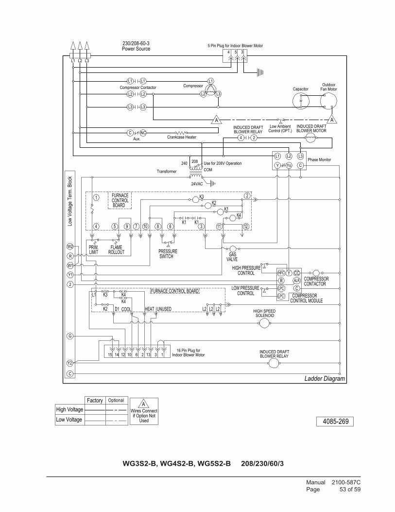
Manual 2100-587CPage 53 of 59
WG3S2-B, WG4S2-B, WG5S2-B 208/230/60/3
if Option Not
AWires Connect
Used
Indoor Blower Motor14 12 10 6 2 13 3 116 Pin Plug for
15
W1
C
HEAT UNUSED
G
High VoltageOptional
Low Voltage
Factory
Phase Monitor
Ladder Diagram
Low
Volta
geTe
rm.B
lock
R
CONTROL MODULE COMPRESSOR
CONTACTORCOMPRESSOR
LOW PRESSURE
CONTROL
LPC
LPC CALR
YHPC CC
HIGH SPEED
2
R
D1
FURNACE CONTROL BOARDK4K4
K3
COOL
PRIM.
L1
HIGH PRESSURE
208
24VAC
240COMTransformer
Use for 208V Operation
BOARDCONTROLFURNACE
VALVE GAS
1
SWITCHPRESSURE
K1K1K4
K1K2
K3
12113
Y
6810794
2
LIMIT ROLLOUT FLAME
Y1
W2
CONTROL
K2
BLOWER RELAYY2
INDUCED DRAFT
5
Yo
Power Source 4 5 3
L1Compressor Contactor
L2
L3
L2
L3
L1
C NC
L2
L1
C
L3
230/208-60-3
SOLENOID
CompressorFan Motor
5 Pin Plug for Indoor Blower Motor
Crankcase HeaterAux.
L1 L2
A
L3
OutdoorCapacitor
Control (OPT.)Low Ambient
BLOWER MOTORINDUCED DRAFT
BLOWER RELAY24
L3L2L1
AINDUCED DRAFT
4085-269
L2L2 L2

Manual 2100-587CPage 54 of 59
WG3S2-B, WG4S2-B, WG5S2-B 208/230/60/3
T2NC
CL2 L3
Aux.
L1
T1 T3
PINK
PINK
L1BLUE
BLUE
543
GR
BLUE
BLUE
1 2 34 5 6
8 971210 11
BLUEBLUE
L2
BLUE
PURPLE
PURPLE
PURPLE
C
MV
NO
MV
YELLOW
ORANGE
YELLOW
YELLOW/BLACK
YELLOW
YELL
OW/B
LACK
BROW
N/W
HITE
YELL
OW/R
ED
YELLOW
YELLOW
YELLOW
YELLOW
YELLOW
RED/WHITE
WHITE
RED
RED
RED
RED
RED/
WHI
TE
RED
RED
RED
RED
RED
RED
RED/WHITE
53
RED
RED/
WHI
TE
RED
49 49
45
43
RED/
RED
FOR INDOOR
BLACK
PIN PLUG
BLACK
(OPT.)
BLAC
K/W
HTIE
16 PIN PLUG FORINDOOR BLOWER
MOTOR
BLACK/WHITE
SOLENOID
BLACK/WHTIE
BLOWER MOTOR
SPEED 150
135
120
FUSE
132
610
13
1512
14
BLAC
K/W
HITE
208/230-60-3BL
ACK
BLAC
K
BLACK
P3
BLACK/WHITE
BROWN
1PL
12
BR
GRAY
BLACK/WHITE
BLACK
BROW
N
BLAC
K/W
HITE
BLACK
BLACK
BROWN
BLAC
K/W
HITE
BLAC
K
BLACK/WHITE
27
TERM. BLOCK
GRAY
L3
YELLOW
ROLLOUT
SPARK IGNITOR
Optional
30
INDUCEDDRAFT BLOWER
COM
PRES
SOR
CONT
ACTO
R
51
GASVALVE
20
32
52
37 35
35
40
40
3535
32
47
T2
32
32
32
32
34
32
32
62
28
2828
37
28
27
27
42
44
41
38
36
47
41
33
2828
28
FLAME
LIMIT
32
38
PRIMARY
FLAME SENSOR
39
PRESSURESWITCH
3232
2835
38
51
51
51
4646
46
T3
48
T1
FieldFactoryHigh VoltageLow Voltage
52
32
15
32
60
60
32
A
32
A
LOW AMBIENTCONTROL (OPT.)
62
47
AWIRES CONNECT
IF OPTIONNOT USED
31
29
4085-255 A
LOW
MOTOR
LPC
VOLTAGE
WHICH IS 250°C HIGH VOLTAGE CABLETEMPERATURE RATING OF AT LEAST 105° C EXCEPT THE IGNITION CABLE
OUTDOORFAN
INTEGRATED FURNACE CONTROL 13
R LPC
53 2
4M
INUT
ES
STRIP 11
28
CIRCUIT BREAKER21
MOVE RED WIRE TO208V TAP FOR 208V
OPERATION
TRANSFORMER18
GROUND TERMINAL
25
PHAS
EM
ONIT
OR
CAPACITOR
19
LOWPRESSURE
SWITCH
INDUCED DRAFTBLOWER RELAY
MODULE
5
4
21
3
240V
208V
COM
R
CONTROL
23
HEATER
C
HIGHPRESSURE
SWITCH
CRANKCASE
HIGH SPEED
16
C
COMPRESSOR
50Compressor
CCHP
C Y
ALR
IF ANY ORIGINAL WIRE AS SUPPLIED WITH THE APPLIANCE MUST BEREPLACED, IT MUST BE REPLACED WITH WIRING MATERIAL HAVING A
USE COPPER CONDUCTORSSUITABLE FOR AT LEAST 75° C
1
Model C. Breaker CapacitorWG3S2-B 30A 10/370WG4S2-B 40A 10/370WG5S2-B 40A 10/370
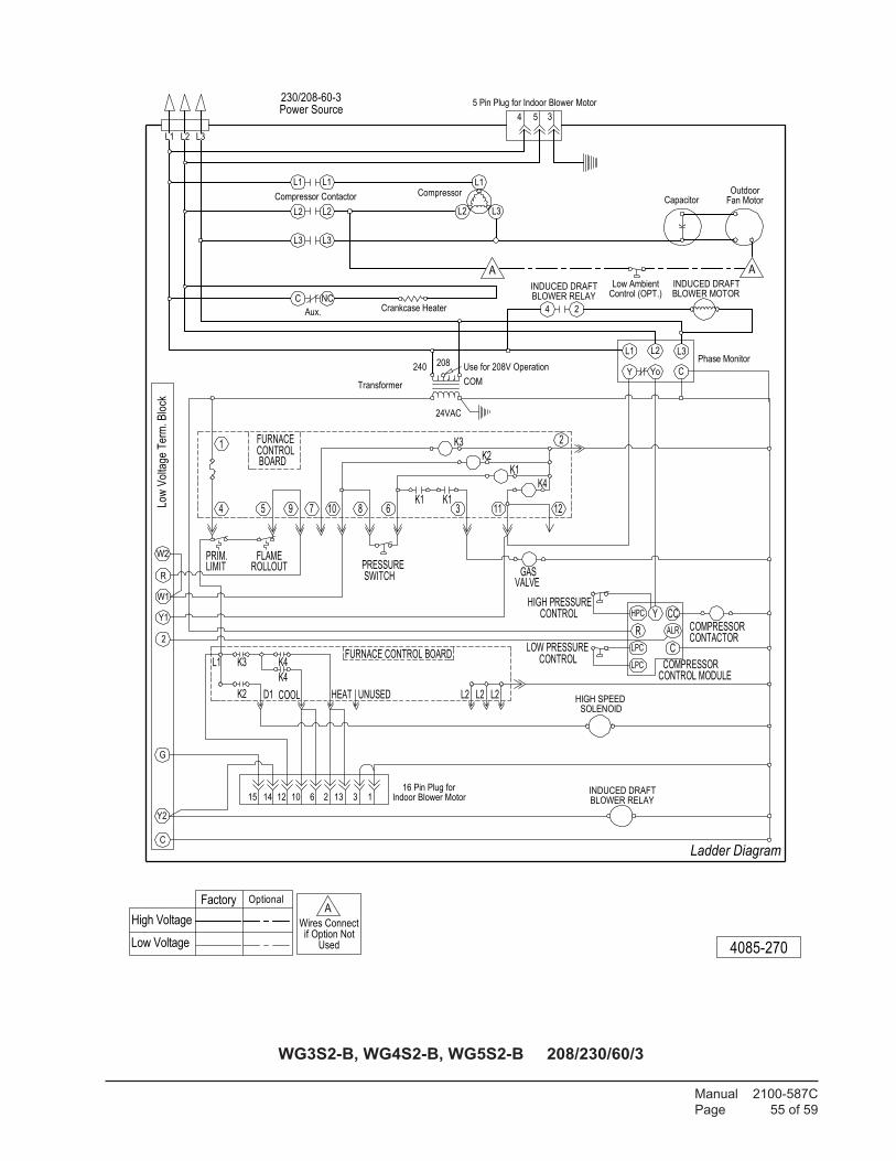
Manual 2100-587CPage 55 of 59
WG3S2-B, WG4S2-B, WG5S2-B 208/230/60/3
if Option Not
AWires Connect
Used
Indoor Blower Motor14 12 10 6 2 13 3 116 Pin Plug for
15
W1
C
HEAT UNUSED
G
High VoltageOptional
Low Voltage
Factory
Phase Monitor
Ladder Diagram
Low
Volta
geTe
rm.B
lock
R
CONTROL MODULE COMPRESSOR
CONTACTORCOMPRESSOR
LOW PRESSURE
CONTROL
LPC
LPC CALR
YHPC CCY1
2
R
FURNACE CONTROL BOARDK4
K2K4
Aux.
COOLD1
L1
HIGH PRESSURE
208
24VAC
240COMTransformer
9
Use for 208V Operation
CONTROLFURNACE
VALVE GAS
1
SWITCHPRESSURE
K1K1K4
K1K2
K3
1211368107
ROLLOUT
54
2
K3
LIMIT FLAMEPRIM.W2
CONTROL
Y
BLOWER RELAYY2
INDUCED DRAFT
SOLENOIDHIGH SPEED
Power Source 4 5 3
L1Compressor Contactor
L2
L3
L2
L3
L1
C NC
L2
L1
C
L3
230/208-60-3
Yo
CompressorFan Motor
5 Pin Plug for Indoor Blower Motor
Crankcase Heater
BOARD
L1 L2
A
L3
OutdoorCapacitor
Control (OPT.)Low Ambient
BLOWER MOTORINDUCED DRAFT
BLOWER RELAY24
L3L2L1
AINDUCED DRAFT
4085-270
L2L2 L2

Manual 2100-587CPage 56 of 59
WG3S2-C, WG4S2-C, WG5S2-C 460/60/3
T2NC
CL2 L3
Aux.
L1
T1 T3
LPC
CCHP
C Y
ALR C
LPC
MIN
UTES
4
235
R
1
460V
230V
PINK
PINK BLUE
BLUE
BLUE
543
GR
BLUE
BLUE
1 2 34 5 6
8 971210 11
BLUE
BLUE
PURPLE
PURPLE
PURPLE
C
MV
NO
MV
YELLOW
ORANGE
YELLOW
YELLOW
RED
YELL
OW/B
LACK
BROW
N/W
HITE
YELL
OW/R
ED
YELLOW
YELLOW
YELLOW
YELLOW
L2L1
YELLOW/BLACK
YELLOW
42
RED
RED
RED
RED/
WHI
TE
RED/WHITE
RED
RED
RED
RED
4
TERM. BLOCK
62
RED/WHITE
49 49
45
53
RED
RED
RED
43
RED
RED
High VoltageFactory Optional
38
Field
Wire Identification numbersfor Bard use only.99
Low Voltage
44
RED
13
26
A
57
RED/WHITE
RED/WHITE
32
A
RED 32
47
RED
(OPT.)
BLACK
BLAC
K
BLACK
BLAC
K
16 PIN PLUG FORINDOOR BLOWER
MOTOR
BLAC
K
TRANSFORMER
SPEED 150
135
120
FUSE
FOR INDOORBLOWER MOTOR
132
610
13
1512
14
BLAC
K/W
HITE
PIN PLUG
460-60-3
BROWN
BLAC
K
BLACK
P3
BLACK/WHITE
STEP DOWN
1PL
12
BR
GRAY
BLACK/WHITE
BLACK
BROW
N
BLAC
K/W
HITE
BLAC
KBLACK
BROWN
BLAC
K/W
HITE
BLAC
K
BLACK/WHITE
BLAC
K/W
HTIE
BLACK/WHTIE
SOLENOID
BLACK/WHITE
BLACK
27
USE COPPER CONDUCTORSSUITABLE FOR AT LEAST 75° C
TERM. BLOCK
GRAY
IF ANY ORIGINAL WIRE AS SUPPLIED WITH THE APPLIANCE MUST BEREPLACED, IT MUST BE REPLACED WITH WIRING MATERIAL HAVING A
TEMPERATURE RATING OF AT LEAST 105° C EXCEPT THE IGNITION CABLEWHICH IS 250°C HIGH VOLTAGE CABLE
OUTDOORFAN
MOTOR
INTEGRATED FURNACE CONTROL 13
11
LOWVOLTAGE
STRIP
28
DISCONNECT21
TRANSFORMER18
GROUND TERMINAL
25
PHAS
EM
ONIT
OR
19 INDUCED DRAFTBLOWER RELAY
23 CAPACITOR
LOWPRESSURE
SWITCH
HIGHPRESSURE
SWITCH
16 COMPRESSORCONTROLMODULE
460V
COM
R
C
COM
PRES
SOR
CONT
ACTO
R
CRANKCASEHEATER
HIGH SPEED
50Compressor
51
INDUCEDDRAFT BLOWER
GASVALVE
20
32
52
37 35
35
40
40
3535
3232
32
32
32
32
34
32
62
28
2828
37
28
27
27
41
38
36
47
41
28
2828
38
39
PRIMARYLIMIT
FLAMEROLLOUT
SPARK IGNITOR
FLAME SENSOR
PRESSURESWITCH
32
2835
51
51
51
4646
46
48
47
T3T1
T2
YELLOW 3130
29
L3
52
32
15
32
4085-377 A
59
59
59
59 59
54
FUSE
BLOC
K
55
56
60
60
32
32
LOW AMBIENTCONTROL (OPT.)
AWIRES CONNECT
IF OPTIONNOT USED
MODELSTEPDOWN
TRANSFORMERCLASS CC FUSE
WG3S 5 AWG4S 7 AWG5S 7 A
33
Model CapacitorWG3S2-C 15/370WG4S2-C 15/370WG5S2-C 15/370

Manual 2100-587CPage 57 of 59
WG3S2-C, WG4S2-C, WG5S2-C 460/60/3
if Option Not
AWires Connect
Used
Indoor Blower Motor14 12 10 6 2 13 3 116 Pin Plug for
15
W1
C
HEAT UNUSED
G
High VoltageOptional
Low Voltage
Factory
Phase Monitor
Ladder Diagram
Low
Volta
geTe
rm.B
lock
R
CONTROL MODULE COMPRESSOR
CONTACTORCOMPRESSOR
LOW PRESSURE
CONTROL
LPC
LPC CALR
YHPC CCY1
2
R
FURNACE CONTROL BOARDK3 K4K4
K2 COOLD1
L1
HIGH PRESSURE
208
24VAC
240COMTransformer
Use for 208V Operation
BOARDCONTROLFURNACE
VALVE GAS
1
SWITCHPRESSURE
K1K1K4
K1K2
K3
1211368107954
2
LIMIT ROLLOUT FLAMEPRIM.W2
CONTROL
Y
BLOWER RELAYY2
INDUCED DRAFT
SOLENOIDHIGH SPEED
Power Source 4 5 3
L1Compressor Contactor
L2
L3
L2
L3
L1
C NC
L2
L1
C
L3
460-60-3
Yo
CompressorFan Motor
5 Pin Plug for Indoor Blower Motor
Crankcase HeaterAux.
L1 L2
A
L3
OutdoorCapacitor
Control (OPT.)Low Ambient
BLOWER MOTORINDUCED DRAFT
BLOWER RELAY24
L3L2L1
AINDUCED DRAFT
4085-392
Transformer
L2 L2 L2
Fuse
Fuse

Manual 2100-587CPage 58 of 59
WG3S2-C, WG4S2-C, WG5S2-C 460/60/3
460V
230V
T2NC
CL2 L3
Aux.
L1
T1 T3
LPC
CCHP
C Y
ALR C
LPC
MINU
TES
4
235
R
1
6
13
24
PINK
PINK
BLUE
BLUE
543
GR
BLUE
BLUE
1 2 34 5 6
8 971210 11
BLUE
BLUE
BLUE
PURPLE
PURPLE
PURPLE
MV
NOC
MV
YELLOW
ORANGEYE
LLOW
/BLA
CK
YELLOW
YELLOW/BLACK YELLOW
YELL
OW/R
ED
YELLOW
YELLOW
YELLOW
YELLOW
L2L1
BROW
N/W
HITE
RED
YELLOW
57
RED
RED
RED
RED/
WHI
TE
RED/WHITE
RED
RED
RED
High Voltage
RED/WHITE
RED/WHITE
49 49
45
53
RED
43
RED
RED
RED
RED
38
for Bard use only.Wire Identification numbers
Factory OptionalField
99
Low Voltage
44
RED42TERM. BLOCK
RED
A
32 REDRED/WHITE
32
A
RED
1
BLAC
K/W
HITE
MOTORINDOOR BLOWER16 PIN PLUG FOR
BLOWER MOTORFOR INDOOR
PIN PLUG
SPEED
460-60-3
135
120
FUSE
132
610
13
1512
14
BLAC
K
TRANSFORMER
(OPT.)
STEP DOWN
BLACK
BLAC
K
BLAC
K
BLAC
K
BLACK
P3
BLACK/WHITE
BROWN
150
PL1
2
BR
GRAY
BLACK/WHITE
BLACK
BROW
N
BLAC
K/W
HITE
BLAC
K
BLACK
BROWN
BLAC
K/W
HITE
BLAC
K
BLACK/WHITE
BLAC
K/W
HTIE
BLACK/WHTIE
SOLENOID
BLACK/WHITE
BLACK
BLACK
27
USE COPPER CONDUCTORSSUITABLE FOR AT LEAST 75° C
TERM. BLOCKGR
AY
IF ANY ORIGINAL WIRE AS SUPPLIED WITH THE APPLIANCE MUST BEREPLACED, IT MUST BE REPLACED WITH WIRING MATERIAL HAVING A
TEMPERATURE RATING OF AT LEAST 105° C EXCEPT THE IGNITION CABLEWHICH IS 250°C HIGH VOLTAGE CABLE
OUTDOORFAN
MOTOR
INTEGRATED FURNACE CONTROL 13
11
LOWVOLTAGE
STRIP
28
DISCONNECT21
TRANSFORMER18
GROUND TERMINAL
25
PHAS
EMO
NITO
R19 INDUCED DRAFT
BLOWER RELAY 23 CAPACITOR
LOWPRESSURE
SWITCH
HIGHPRESSURE
SWITCH
16 COMPRESSORCONTROLMODULE
460V
COM
R
C
COMP
RESS
ORCO
NTAC
TOR
CRANKCASEHEATER
HIGH SPEED
50Compressor
51
INDUCEDDRAFT BLOWER
GASVALVE
20
32
52
37
3535
40
40
35
35
3232
32
32
32
32
34
32
62
28
2828
37
33
28
27
27
41
38
36
47
41
2828
28
38
39
PRIMARYLIMIT
FLAMEROLLOUT
SPARK IGNITOR
FLAME SENSOR
PRESSURESWITCH
32
2835
51
51
51
4646
46
48
47
T3T1
T2
YELLOW 3130
29
L3
52
32
15
32
4085-378 A
59
59
59
59 59
54
FUSE
BLOC
K
55
56
60
60
32
32
LOW AMBIENTCONTROL (OPT.)
AWIRES CONNECT
IF OPTIONNOT USED
62
MODELSTEPDOWN
TRANSFORMERCLASS CC FUSE
WG3S 5 AWG4S 7 AWG5S 7 A
47
Model CapacitorWG3S2-C 15/370WG4S2-C 15/370WG5S2-C 15/370

Manual 2100-587CPage 59 of 59
WG3S2-C, WG4S2-C, WG5S2-C 460/60/3
if Option Not
AWires Connect
Used 4085-393
Indoor Blower Motor14 12 10 6 2 13 3 116 Pin Plug for
15
W1
C
HEAT UNUSED
G
High VoltageOptional
Low Voltage
Factory
COMPRESSOR
Ladder Diagram
Low
Volta
geTe
rm.B
lock
R
CONTROL MODULECOMPRESSOR
CONTACTOR
INDUCED DRAFT
FURNACE
CONTROL
LPC
LPC CALR
YHPC CCY1
2
R
FURNACE CONTROL BOARDK3 K4K4
K2 COOLD1
LOW PRESSURE
HIGH PRESSURE
208
24VAC
240COMTransformer
Use for 208V Operation
6
BOARD
L1
VALVEGAS
1
SWITCHPRESSURE
K1K1K4
K1K2
K3
1211
CONTROL
38107954
2
W2ROLLOUT
FLAMEPRIM.
CONTROL
LIMIT
2
BLOWER RELAYY2
INDUCED DRAFT
SOLENOIDHIGH SPEED
Power Source 4 5 3
L1Compressor Contactor
L2
L3
L2
L3
L1
C NC
L2
L1
BLOWER MOTOR
L3
460-60-3
4
CompressorFan Motor
5 Pin Plug for Indoor Blower Motor
Crankcase HeaterAux.
L1 L2
A
L3
OutdoorCapacitor
Control (OPT.)
L3L2L1
CYoYPhase Monitor
Low AmbientA
INDUCED DRAFTBLOWER RELAY
Transformer
L2 L2 L2
Fuse
Fuse