Embed Size (px)
Citation preview
21/09/04 www.eej.ulster.ac.uk/~ian/modules/COM342/COM342_L2.ppt L2/1
COM342Networks and Data Communications
Ian McCrum Room 5B18
Tel: 90 366364 voice mail on 6th ring
Email: [email protected]
Web site: http://www.eej.ulst.ac.uk
Lecture 2: Fundamentals and Theory at the Physical layer
21/09/04 www.eej.ulster.ac.uk/~ian/modules/COM342/COM342_L2.ppt L2/2
Keypoints from last lecture• Read chapter 1 of the text• A distributed system is not a “Computer Network• Layers are used to manage complexity. • Only bottom layers can communicate across machines• Protocol stacks are used to help manage complexity• Different topologies exist: Bus or Ring• Broadcast and Peer to Peer• WANs, MANs and LANs… linking using routers/switches• Connection orientated or connectionless• Reliable or unreliable, both are useful
21/09/04 www.eej.ulster.ac.uk/~ian/modules/COM342/COM342_L2.ppt L2/3
Fundamentals of communications
• Voltages as Data, a way of passing information
• timing considerations
• data transfer
• Synchronous and asynchronous communications
• redundancy
• genesis of a protocol .
• Serial or parallel
• Broadcast or peer to peer
• Direction; Duplex or Simplex
21/09/04 www.eej.ulster.ac.uk/~ian/modules/COM342/COM342_L2.ppt L2/4
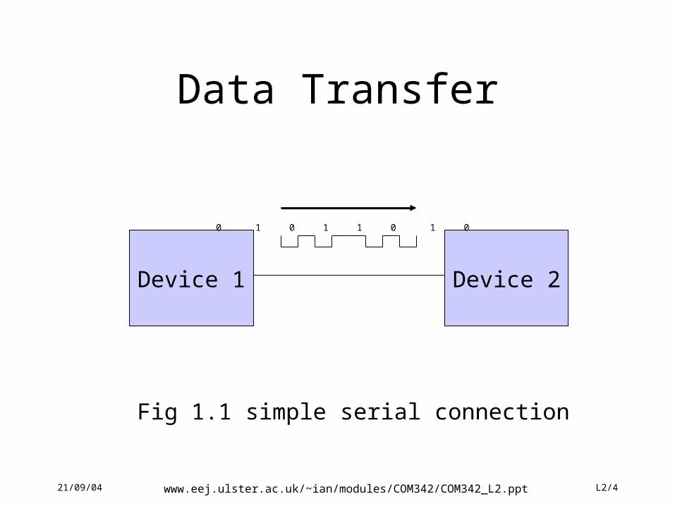
Data Transfer
Device 1 Device 2
Fig 1.1 simple serial connection
0 1 0 1 1 0 1 0
21/09/04 www.eej.ulster.ac.uk/~ian/modules/COM342/COM342_L2.ppt L2/5
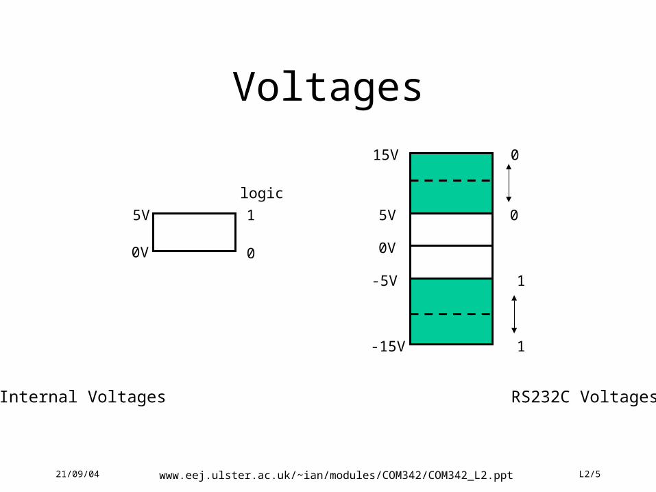
Voltages
0V
5V 1
0
logic
5V
0V
-5V
-15V
15V
0
1
1
0
Internal Voltages RS232C Voltages
21/09/04 www.eej.ulster.ac.uk/~ian/modules/COM342/COM342_L2.ppt L2/6
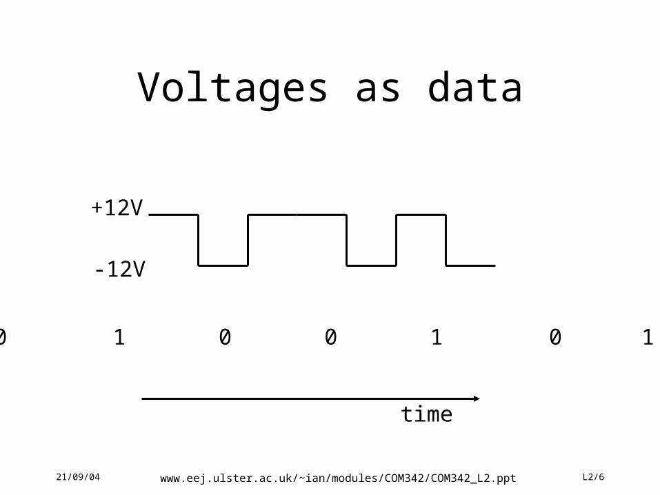
Voltages as data
0 1 0 0 1 0 1
+12V
-12V
time
21/09/04 www.eej.ulster.ac.uk/~ian/modules/COM342/COM342_L2.ppt L2/7
Timing of signals
• Consider that each state was of 10ms in duration
• this means that 100 such states could be set in 1s
• or expressed as 100bits per second (100bps)
• i.e.period / number of bits
• consider 28,000bps what it the time needed for each bit
• What are the problems?
21/09/04 www.eej.ulster.ac.uk/~ian/modules/COM342/COM342_L2.ppt L2/8
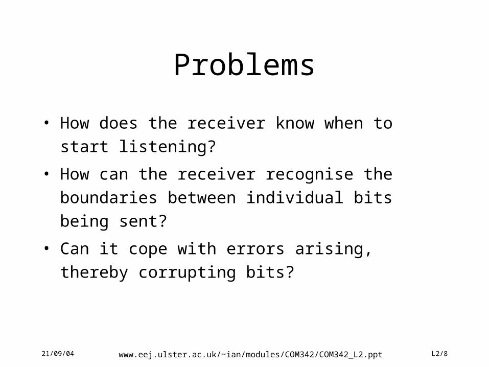
Problems
• How does the receiver know when to start listening?
• How can the receiver recognise the boundaries between
individual bits being sent?
• Can it cope with errors arising, thereby corrupting bits?
21/09/04 www.eej.ulster.ac.uk/~ian/modules/COM342/COM342_L2.ppt L2/9
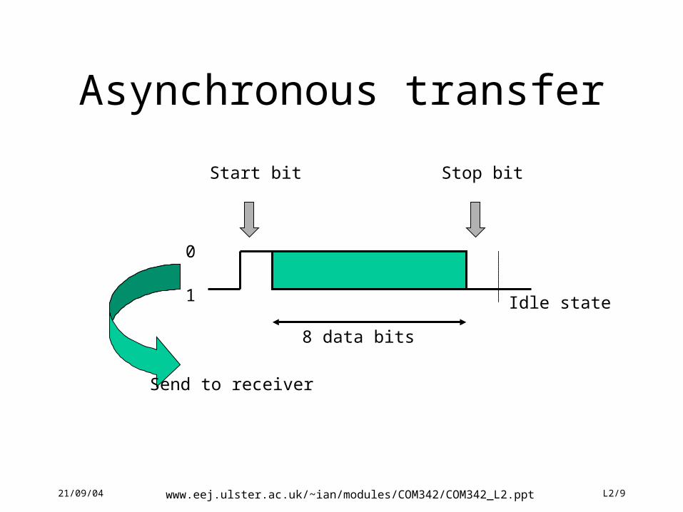
Asynchronous transfer
1
0
Start bit Stop bit
8 data bits
Send to receiver
Idle state
21/09/04 www.eej.ulster.ac.uk/~ian/modules/COM342/COM342_L2.ppt L2/10
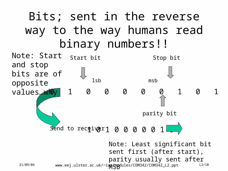
Bits; sent in the reverse way to the way humans read binary numbers!!
Start bit Stop bit
Send to receiver
0 1 0 0 0 0 0 1 0 1
lsb msb
parity bit
1 0 1 0 0 0 0 0 1 0
Note: Start and stop bits are of opposite values…why
Note: Least significant bit sent first (after start), parity usually sent after MSB
21/09/04 www.eej.ulster.ac.uk/~ian/modules/COM342/COM342_L2.ppt L2/11
Timing
• In order to receive a data transmission correctly the receiver must be clocking at the same rate.
• This must be established before data is transferred.
• Some systems over-sample at 16 time the bit rate in order to avoid the transitions.
• The receiver will also check the framing i.e. check that the stop appears where it should.
21/09/04 www.eej.ulster.ac.uk/~ian/modules/COM342/COM342_L2.ppt L2/12
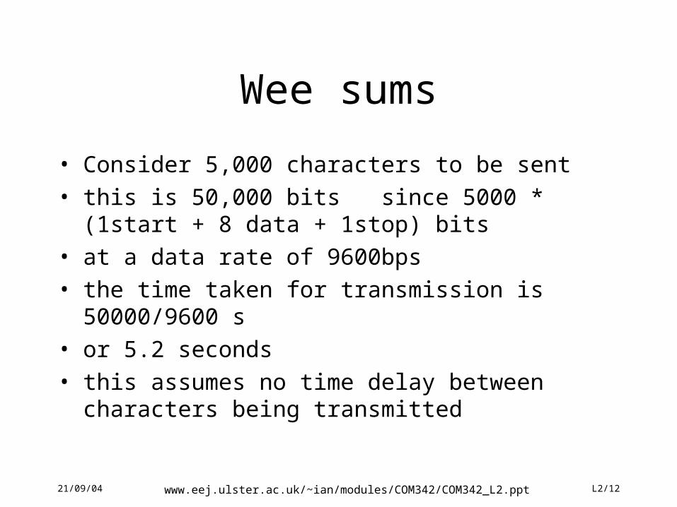
Wee sums
• Consider 5,000 characters to be sent
• this is 50,000 bits since 5000 * (1start + 8 data + 1stop) bits
• at a data rate of 9600bps
• the time taken for transmission is 50000/9600 s
• or 5.2 seconds
• this assumes no time delay between characters being transmitted
21/09/04 www.eej.ulster.ac.uk/~ian/modules/COM342/COM342_L2.ppt L2/13
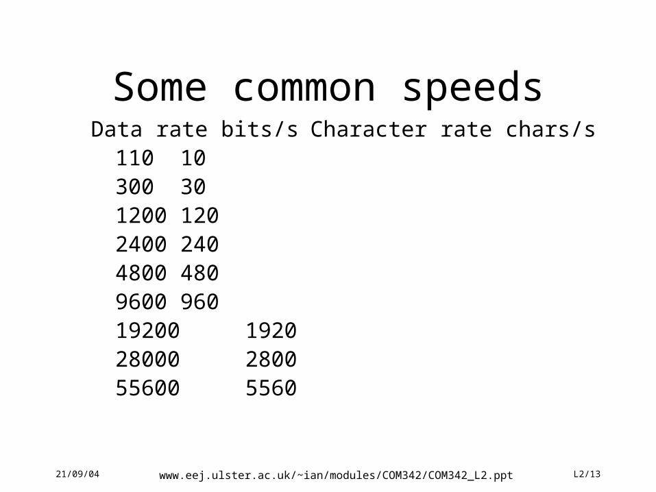
Some common speedsData rate bits/s Character rate chars/s
110 10300 301200 1202400 2404800 4809600 96019200 192028000 280055600 5560
21/09/04 www.eej.ulster.ac.uk/~ian/modules/COM342/COM342_L2.ppt L2/14
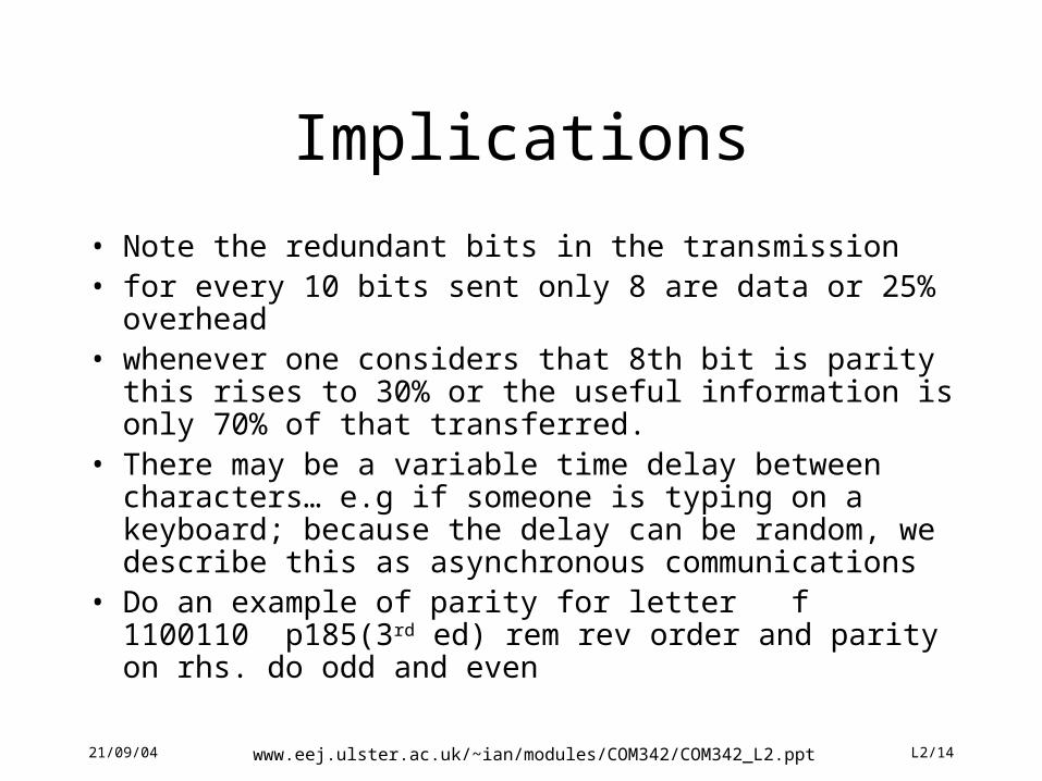
Implications
• Note the redundant bits in the transmission• for every 10 bits sent only 8 are data or 25% overhead• whenever one considers that 8th bit is parity this rises to
30% or the useful information is only 70% of that transferred.
• There may be a variable time delay between characters… e.g if someone is typing on a keyboard; because the delay can be random, we describe this as asynchronous communications
• Do an example of parity for letter f 1100110 p185(3rd ed) rem rev order and parity on rhs. do odd and even
21/09/04 www.eej.ulster.ac.uk/~ian/modules/COM342/COM342_L2.ppt L2/15
Parity
• What are the limitations of parity?
• How many errors can it detect?
• Can it correct an error in one codeword?
• Could we use parity to detect an error?
• Consider Chinese whispers.
• How do we correct errors in English?
21/09/04 www.eej.ulster.ac.uk/~ian/modules/COM342/COM342_L2.ppt L2/16
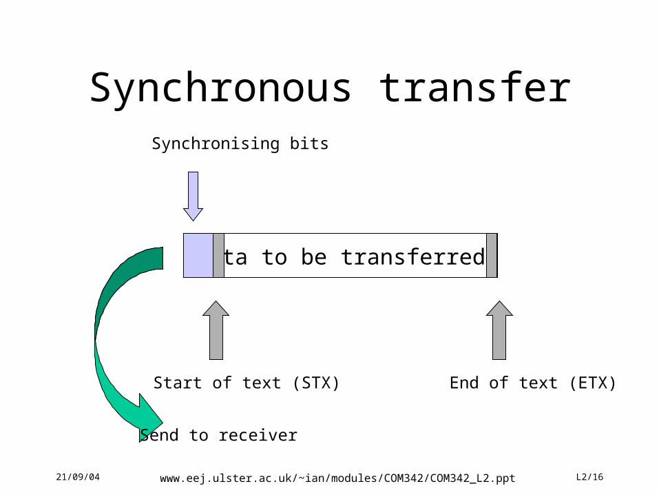
Synchronous transfer
Data to be transferred
Synchronising bits
Start of text (STX) End of text (ETX)
Send to receiver
21/09/04 www.eej.ulster.ac.uk/~ian/modules/COM342/COM342_L2.ppt L2/17
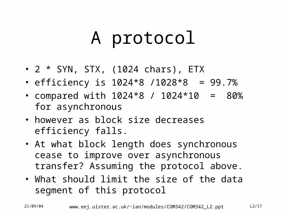
A protocol
• 2 * SYN, STX, (1024 chars), ETX
• efficiency is 1024*8 /1028*8 = 99.7%
• compared with 1024*8 / 1024*10 = 80% for asynchronous
• however as block size decreases efficiency falls.
• At what block length does synchronous cease to improve over asynchronous transfer? Assuming the protocol above.
• What should limit the size of the data segment of this protocol
21/09/04 www.eej.ulster.ac.uk/~ian/modules/COM342/COM342_L2.ppt L2/18
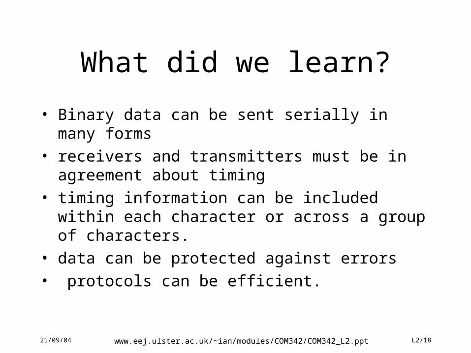
What did we learn?
• Binary data can be sent serially in many forms
• receivers and transmitters must be in agreement about timing
• timing information can be included within each character or across a group of characters.
• data can be protected against errors
• protocols can be efficient.
21/09/04 www.eej.ulster.ac.uk/~ian/modules/COM342/COM342_L2.ppt L2/19
21/09/04 www.eej.ulster.ac.uk/~ian/modules/COM342/COM342_L2.ppt L2/20
Theoretical Communication Rate
• What form the signal takes.
• Mathematical description
• Nyquist’s limitation
• Shannon’s theorem
• Carrying data using sine waves
21/09/04 www.eej.ulster.ac.uk/~ian/modules/COM342/COM342_L2.ppt L2/21
Fourier Series g t c a nft b nftn
n
n
n
12
1 1
2 2sin cos
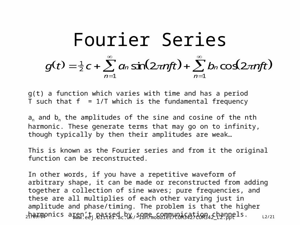
g(t) a function which varies with time and has a periodT such that f = 1/T which is the fundamental frequency
an and bn the amplitudes of the sine and cosine of the nth harmonic. These generate terms that may go on to infinity, though typically by then their amplitudes are weak…
This is known as the Fourier series and from it the original function can be reconstructed.
In other words, if you have a repetitive waveform of arbitrary shape, it can be made or reconstructed from adding together a collection of sine waves; pure frequencies, and these are all multiplies of each other varying just in amplitude and phase/timing. The problem is that the higher harmonics aren’t passed by some communication channels.
21/09/04 www.eej.ulster.ac.uk/~ian/modules/COM342/COM342_L2.ppt L2/22
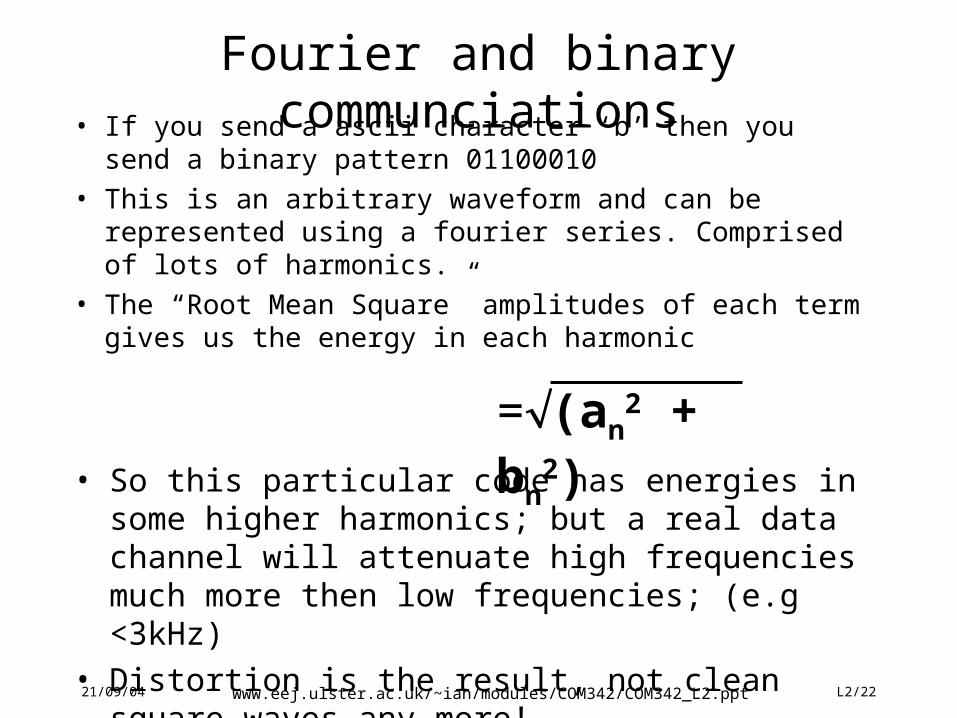
Fourier and binary communciations• If you send a ascii character ‘b’ then you send a binary
pattern 01100010
• This is an arbitrary waveform and can be represented using a fourier series. Comprised of lots of harmonics.
• The “Root Mean Square” amplitudes of each term gives us the energy in each harmonic
=(an2 + bn
2)• So this particular code has energies in some higher
harmonics; but a real data channel will attenuate high frequencies much more then low frequencies; (e.g <3kHz)
• Distortion is the result, not clean square waves any more!
21/09/04 www.eej.ulster.ac.uk/~ian/modules/COM342/COM342_L2.ppt L2/23
21/09/04 www.eej.ulster.ac.uk/~ian/modules/COM342/COM342_L2.ppt L2/24
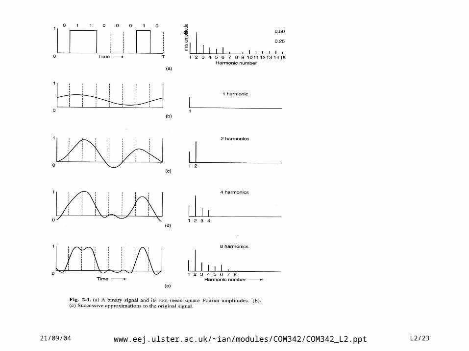
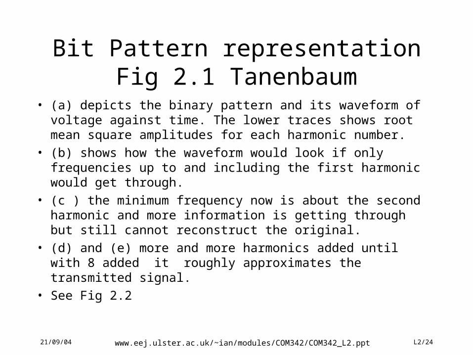
Bit Pattern representation Fig 2.1 Tanenbaum
• (a) depicts the binary pattern and its waveform of voltage against time. The lower traces shows root mean square amplitudes for each harmonic number.
• (b) shows how the waveform would look if only frequencies up to and including the first harmonic would get through.
• (c ) the minimum frequency now is about the second harmonic and more information is getting through but still cannot reconstruct the original.
• (d) and (e) more and more harmonics added until with 8 added it roughly approximates the transmitted signal.
• See Fig 2.2
21/09/04 www.eej.ulster.ac.uk/~ian/modules/COM342/COM342_L2.ppt L2/25
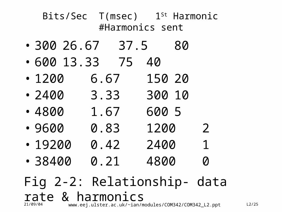
Bits/Sec T(msec) 1St Harmonic #Harmonics sent
• 300 26.67 37.5 80• 600 13.33 75 40• 1200 6.67 150 20• 2400 3.33 300 10• 4800 1.67 600 5• 9600 0.83 1200 2• 19200 0.42 2400 1• 38400 0.21 4800 0
Fig 2-2: Relationship- data rate & harmonics
21/09/04 www.eej.ulster.ac.uk/~ian/modules/COM342/COM342_L2.ppt L2/26
Baud v bits/sec
• 1 baud is a change of state per second• not to be confused with 1 bit/sec which is 1 bit/sec• if a change of state represents only one bit then
1 baud is 1 bit/sec• many cases a change of state represents 2, 3, or
more bits. If the voltages 0,1,2,3,4,5,6 and 7 were used , each signal change conveys 3 bits, the bit rate is three times the baud rate.
21/09/04 www.eej.ulster.ac.uk/~ian/modules/COM342/COM342_L2.ppt L2/27
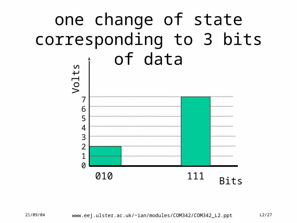
one change of state corresponding to 3 bits of data
76543210
Vol
ts
010 111 Bits
21/09/04 www.eej.ulster.ac.uk/~ian/modules/COM342/COM342_L2.ppt L2/28
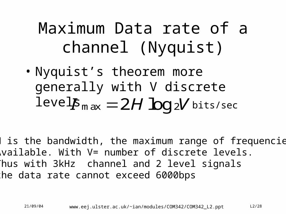
Maximum Data rate of a channel (Nyquist)
• Nyquist’s theorem more generally with V discrete levels
I H Vmax log2 2 bits/sec
H is the bandwidth, the maximum range of frequencies Available. With V= number of discrete levels.Thus with 3kHz channel and 2 level signalsthe data rate cannot exceed 6000bps
21/09/04 www.eej.ulster.ac.uk/~ian/modules/COM342/COM342_L2.ppt L2/29
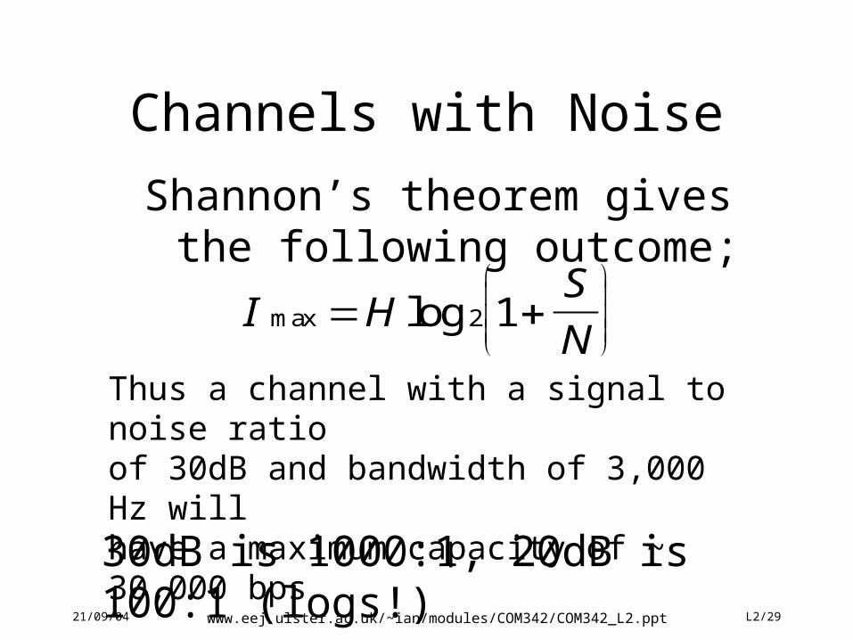
Channels with Noise
Shannon’s theorem gives the following outcome;
I HS
Nmax log
2 1
Thus a channel with a signal to noise ratioof 30dB and bandwidth of 3,000 Hz willhave a maximum capacity of ~ 30,000 bps
30dB is 1000:1, 20dB is 100:1 (logs!)
21/09/04 www.eej.ulster.ac.uk/~ian/modules/COM342/COM342_L2.ppt L2/30
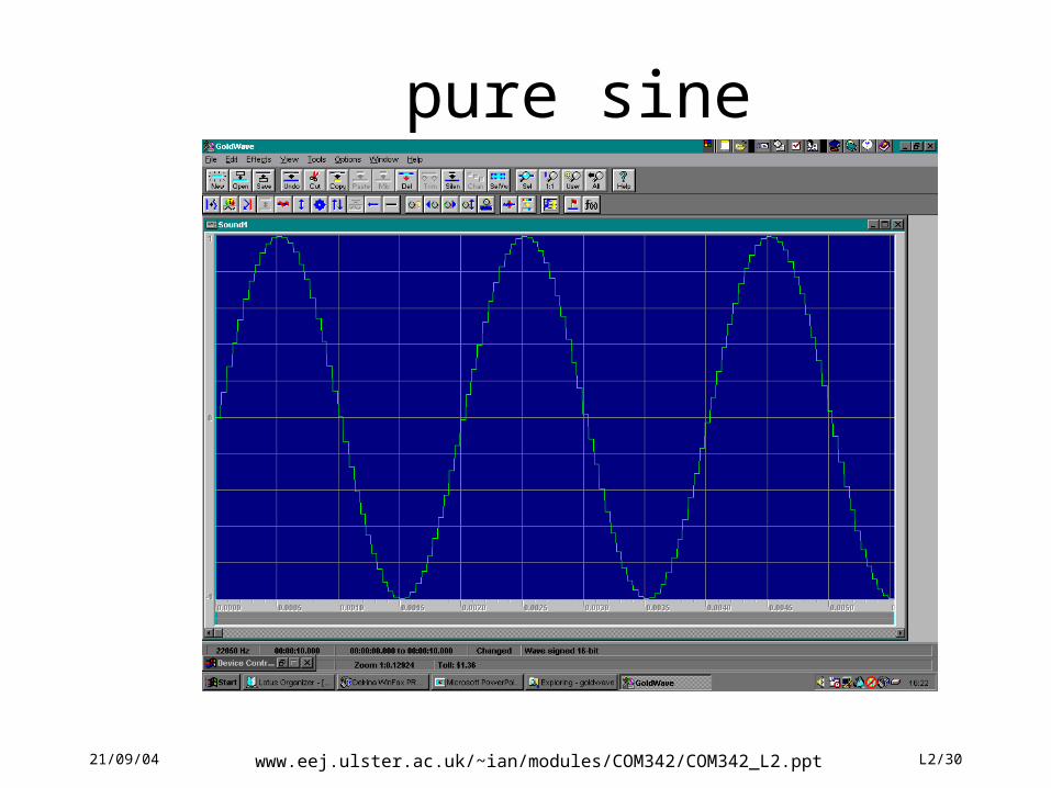
pure sine
21/09/04 www.eej.ulster.ac.uk/~ian/modules/COM342/COM342_L2.ppt L2/31
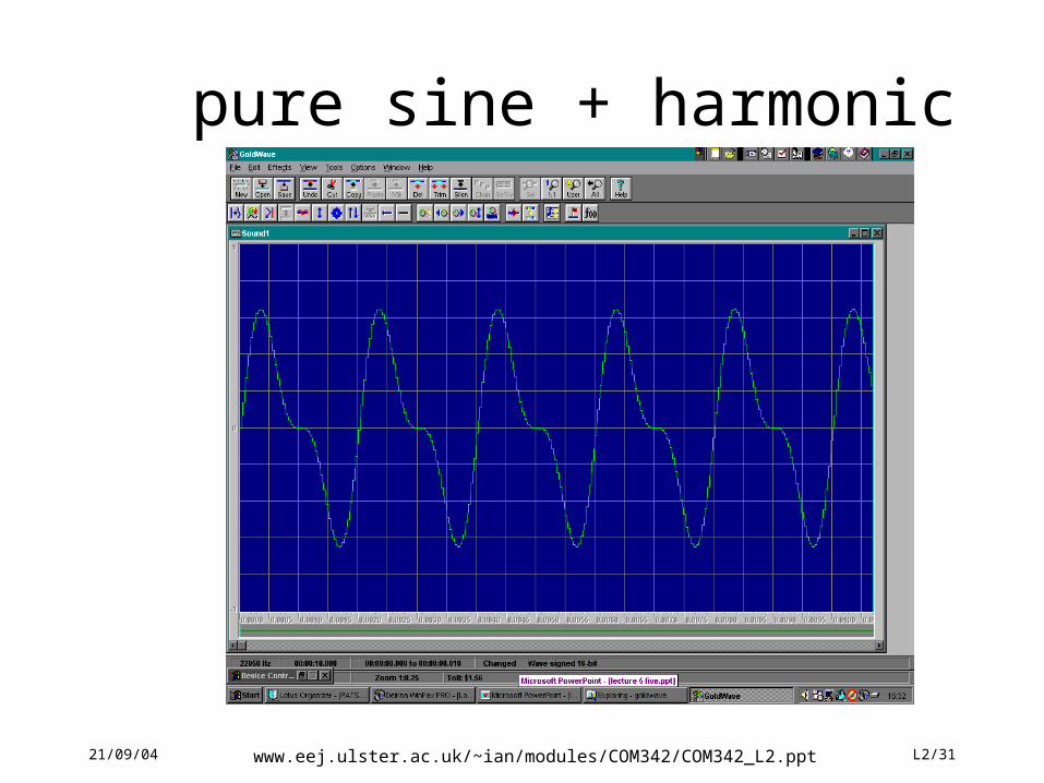
pure sine + harmonic
21/09/04 www.eej.ulster.ac.uk/~ian/modules/COM342/COM342_L2.ppt L2/32
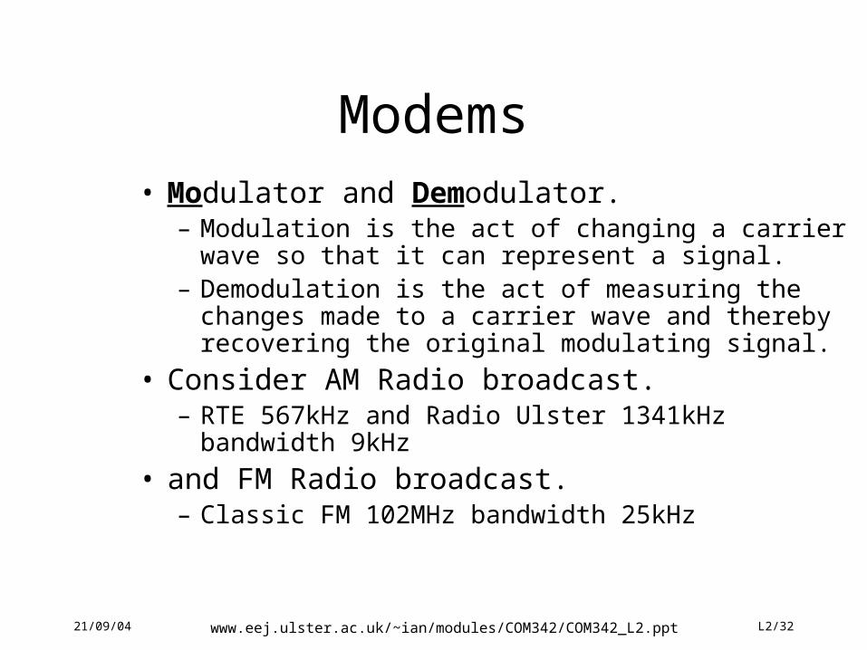
Modems• Modulator and Demodulator.
– Modulation is the act of changing a carrier wave so that it can represent a signal.
– Demodulation is the act of measuring the changes made to a carrier wave and thereby recovering the original modulating signal.
• Consider AM Radio broadcast.– RTE 567kHz and Radio Ulster 1341kHz bandwidth 9kHz
• and FM Radio broadcast.– Classic FM 102MHz bandwidth 25kHz
21/09/04 www.eej.ulster.ac.uk/~ian/modules/COM342/COM342_L2.ppt L2/33
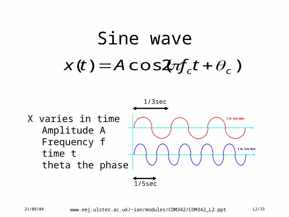
Sine wave
)2cos()( cctfAtx
X varies in time Amplitude AFrequency ftime ttheta the phase
3 Hz Sine Wave
5 Hz Sine Wave
1/3sec
1/5sec
21/09/04 www.eej.ulster.ac.uk/~ian/modules/COM342/COM342_L2.ppt L2/34
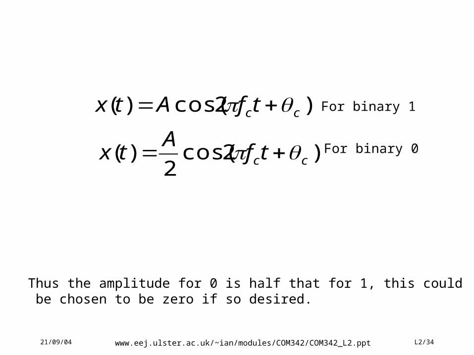
)2cos()( cctfAtx
)2cos(2
)( cctfA
tx
For binary 1
For binary 0
Thus the amplitude for 0 is half that for 1, this could be chosen to be zero if so desired.
1 1 1 110 0Data
Amplitude Modulation
21/09/04 www.eej.ulster.ac.uk/~ian/modules/COM342/COM342_L2.ppt L2/35
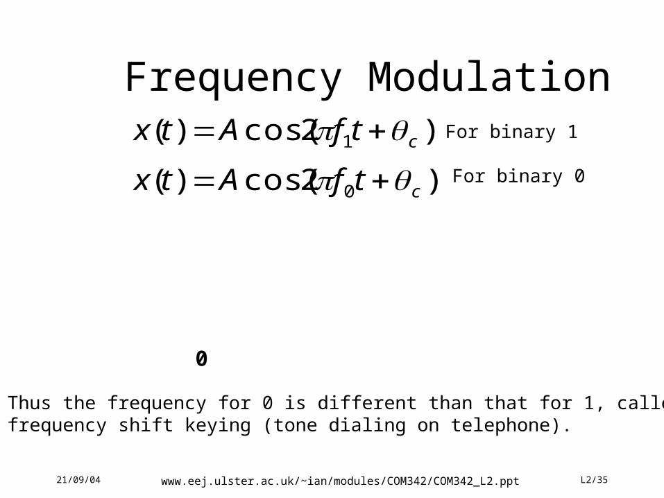
Frequency Modulation)2cos()( 1 ctfAtx
)2cos()( 0 ctfAtx
For binary 1
For binary 0
Thus the frequency for 0 is different than that for 1, called frequency shift keying (tone dialing on telephone).
0 1 10Data
0 0 0
21/09/04 www.eej.ulster.ac.uk/~ian/modules/COM342/COM342_L2.ppt L2/36
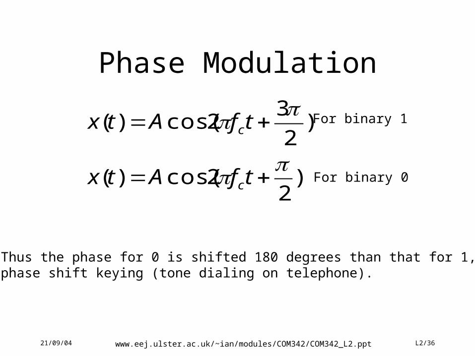
Phase Modulation
)2
2cos()( tfAtx c
)2
32cos()(
tfAtx cFor binary 1
For binary 0
Thus the phase for 0 is shifted 180 degrees than that for 1, called phase shift keying (tone dialing on telephone).
21/09/04 www.eej.ulster.ac.uk/~ian/modules/COM342/COM342_L2.ppt L2/37
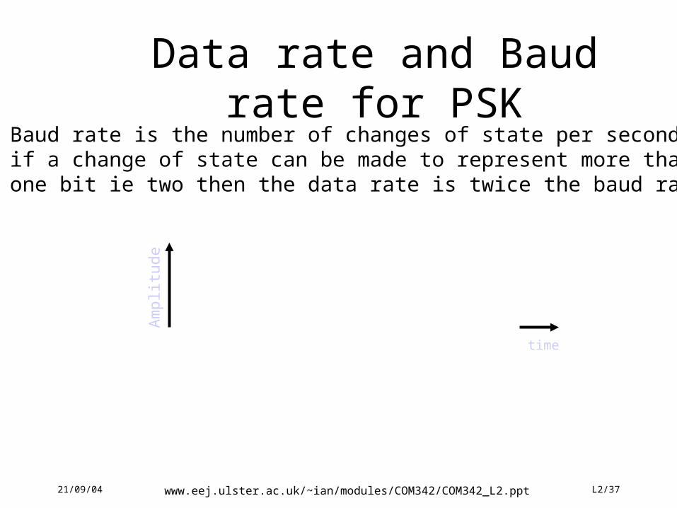
Data rate and Baud rate for PSKBaud rate is the number of changes of state per secondif a change of state can be made to represent more thanone bit ie two then the data rate is twice the baud rate
time
Am
plit
ude
01 11Data
11 11
21/09/04 www.eej.ulster.ac.uk/~ian/modules/COM342/COM342_L2.ppt L2/38
Note how the addition of 2 levels of AM enable another bit to be
encoded with each baud
000 111 110
21/09/04 www.eej.ulster.ac.uk/~ian/modules/COM342/COM342_L2.ppt L2/39
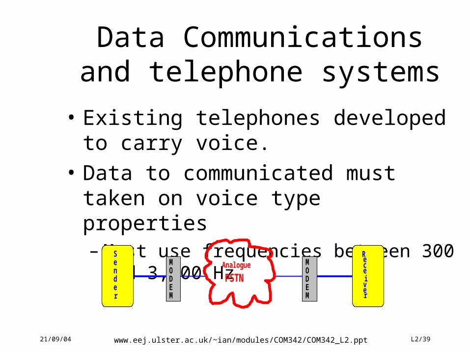
Data Communications and telephone systems
• Existing telephones developed to carry voice.
• Data to communicated must taken on voice type properties– Must use frequencies between 300 and 3,400
HzAnalogue
PSTN
Sender
Receiver
MODEM
MODEM
21/09/04 www.eej.ulster.ac.uk/~ian/modules/COM342/COM342_L2.ppt L2/40
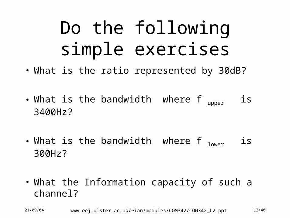
Do the following simple exercises
• What is the ratio represented by 30dB?
• What is the bandwidth where f upper is 3400Hz?
• What is the bandwidth where f lower is 300Hz?
• What the Information capacity of such a channel?
21/09/04 www.eej.ulster.ac.uk/~ian/modules/COM342/COM342_L2.ppt L2/41
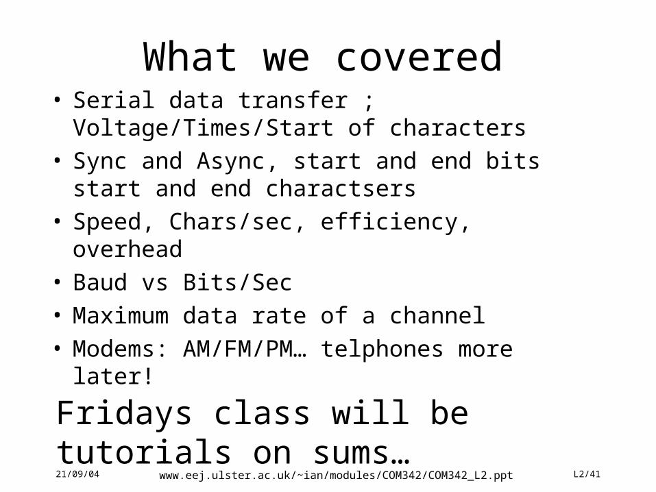
What we covered• Serial data transfer ; Voltage/Times/Start of
characters• Sync and Async, start and end bits start and end
charactsers• Speed, Chars/sec, efficiency, overhead• Baud vs Bits/Sec• Maximum data rate of a channel• Modems: AM/FM/PM… telphones more later!
Fridays class will be tutorials on sums…