Embed Size (px)
Citation preview
2
H
hiBln
2N-ine
ree
r, p
e p
ial
n RS232C devices is specified through buffer mem-
RS232C conne
DIN rail clip
DIN rail groove
hi
ec
en
N
ig
hi
NO
N
hi
2
ection Example
wiring of the RS232C equipment varies depending on the RS232C specifications connected.specifications of the RS232C equipment used, then connect the signals correctly. Representa-examples are shown below.
ction with counterpart equipment of terminal specifications (when control line is not used)0 communication format: b9 = 0, b8 = 0, without control line
Communication is performed in accordancewith the condition determined by the soft-ware in the 232IF and the counterpart equip-ment.
side
PinNo.
3
) 2
) 5
RS232C device side
Signalname
9-pinD-SUB
25-pinD-SUB
SD(TXD) 3 2
RD(RXD) 2 3
SG(GND) 5 7
ction with counterpart equipment of terminal specifications (when control line is used)able used, BFM #0 communication format: b9 = 0, b8 = 1, standard RS232C mode
Because the carrier to send (CS) signal pinof the 232IF itself receives the request tosend (RS) signal, signal transfer is per-formed as if the counterpart equipment isfunctioning.
*1 When the CD signal is not monitored, theCD signal pin is not required to be con-nected. The 232IF only monitors the sig-nal status (ON/OFF).
*2 The 232IF only monitors the signal status(ON/OFF).
side
PinNo.
3
2
7
8
) 1
4
6
) 5
RS232C device side
Signalname
9-pinD-SUB
25-pinD-SUB
SD(TXD) 3 2
RD(RXD) 2 3
RS(RTS) 7 4
CS(CTS) 8 5
CD(DCD) 1 8
ER(DTR) 4 20
DR(DSR) 6 6
SG(GND) 5 7
*1
*2
k serial cross cable used, 0 communication format: b9 = 1, b8 = 1, RS232C interlink connection mode
In the interl ink connection mode, dataexceeding 512 bytes (upper limit of thereceive buffer in the 232IF) can be received.
*1 In this mode, the Request to Send signal(RS) functions as the receive enable sig-nal in the 232IF. When receiving data thatexceeds 512 bytes (the upper limit of the232IF receive buffer), the 232IF sets theRequest to Send signal (RS) to “OFF”and requests the counterpart equipmentto suspend the data transmission. Oncethe data saved in the receive buffer isread by the sequence program, theremaining data can be received.
*2 The 232IF only monitors the signal status(ON/OFF).
side
PinNo.
3
2
7
8
4
6
) 5
RS232C device side
Signalname
9-pinD-SUB
25-pinD-SUB
SD(TXD) 3 2
RD(RXD) 2 3
RS(RTS) 7 4
CS(CTS) 8 5
ER(DTR) 4 20
DR(DSR) 6 6
SG(GND) 5 7
*1
*2
ction with counterpart equipment of modem specifications (Control line is essential.)t cable used, BFM #0 communication format: b9 = 0, b8 = 1, standard RS232C mode
side
PinNo.
3
2
7
8
) 1
4
6
) 5
9
RS232C device side
Signalname
9-pinD-SUB
25-pinD-SUB
SD(TXD) 3 2
RD(RXD) 2 3
RS(RTS) 7 4
CS(CTS) 8 5
CD(DCD) 1 8
ER(DTR) 4 20
DR(DSR) 6 6
SG(GND) 5 7
CI(RI) 9 22
*1 When the CD signal is not being moni-tored, the CD signal pin is not requiredto be connected. The 232IF only moni-tors the signal status (ON/OFF).
*2 The 232IF only monitors the signal sta-tus (ON/OFF).
*3 When the CI signal is not required, theCI signal pin is not required to be con-nected. The 232IF only monitors thesignal status (ON/OFF).
*1
*2
*3
ctor (9-pin D-SUB connector: #4-40unc inch screw thread
(35(1.38"))
)
#
is 0.5 to 0.8 N m.Do not tighten the terminal block mountoutside the above-mentioned range.Failure to do so may cause equipment fai
ing screws with a torque
lures or malfunctions.
SG(GND
CI(RI)
ory (BFM). The FROM/TO instruction is used for th
3) The send/receive buffer can accommodate 512 bytWhen the RS232C interlink connection mode is uscan be received.
4) ASCII/HEX conversion functionThe function to convert and send and a hexadecimawell as the function to convert a received ASCII coto the receive buffer are provided.
*1 Up to 7 special function block can be connected to
2. Specifications
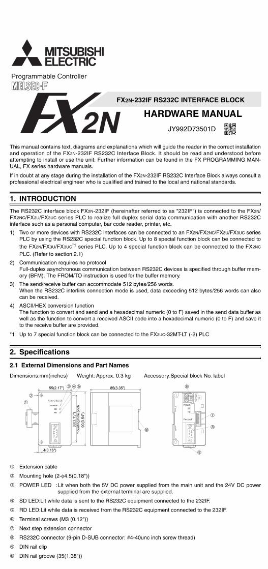
2.1 External Dimensions and Part Names
Dimensions:mm(inches) Weight: Approx. 0.3 kg
➀
!
"
#
(
➁
➂ ➃ ➄
Extension cable
Mounting hole (2-φ4.5(0.18"))
POWER LED :Lit when both the 5V DC power susupplied from the external terminal
SD LED:Lit while data is sent to the RS232C equip
RD LED:Lit while data is received from the RS232C
Terminal screws (M3 (0.12"))
Next step extension connector
e buffer memory.
es/256 words.ed, data exceeding 512 bytes/256 words can also
l numeric (0 to F) saved in the send data buffer asde into a hexadecimal numeric (0 to F) and save it
the FX3UC-32MT-LT (-2) PLC
Accessory:Special block No. label
$%&$'
➉
➅
➈
➆
➇
pplied from the main unit and the 24V DC power are supplied.
ment connected to the 232IF.
equipment connected to the 232IF.
PL-1P
3. WI
3.1 Co
The 232the righfrom theconnecFX2NC Sis limitecurrent that ava
*1 Up
3.2 Po
Handlin
Class Dgroundi100 Ω o
C, either the FX2NC-CNV-IF or FX3UC-S-5V is required.
RING AND CONNECTION
nnection with the programmable controller
IF can be connected to the FX2N/FX2NC/FX3U/FX3UC programt side of another extension block/unit. A number is assigned one nearest the main unit in the way of No.0, No.1. . . No.7
ted to the FX2N/FX3U/FX3UC*1 Series PLC. Up to 4 FX2N-23eries PLC. However, the capacity of the 5V DC power supplie
d. The current consumption of the 5V DC power in the 232IFconsumption of the 5V DC power supply including other speciailable.
to 7 units can be connected to an FX3UC-32MT-LT (-2) PLC
wer Supply Wiring
g of the crimp-style terminalUse the crimp-style terminals oure on the left. Make sure that t
FX2Nprogrammablecontroller
Extensioncable
FX2N-232IF
DC service supply
ngr less 24+
24-
0V 24V
#
mable controller or connected onto each special unit/block counting". Up to 8 FX2N-232IF units can be2IF units can be connected to thed from the programmable controller is 40 mA. Make sure that the totall blocks is equivalent to or less than
f the dimensions shown on the fig-he tightening torque of the terminal
DC service supply ofprogrammable controllermay be used.
24V DC±10%80mA
3) InterlinBFM #
232IF
Signalname
SD(TXD)
RD(RXD)
RS(RTS)
CS(CTS)
ER(DTR)
DR(DSR)
SG(GND
4) ConneStraigh
232IF
Signalname
SD(TXD)
RD(RXD)
RS(RTS)
CS(CTS)
CD(DCD
ER(DTR)
DR(DSR)
FX2N-23
This manual contains text, diagrams and explanations wand operation of the FX2N-232IF RS232C Interface attempting to install or use the unit. Further informatioUAL, FX series hardware manuals.
If in doubt at any stage during the installation of the FXprofessional electrical engineer who is qualified and tra
1. INTRODUCTION
The RS232C interface block FX2N-232IF (hereinafter FX2NC/FX3U/FX3UC series PLC to realize full duplex sinterface such as a personal computer, bar code reade
1) Two or more devices with RS232C interfaces can bPLC by using the RS232C special function block. Uthe FX2N/FX3U/FX3UC*1 series PLC. Up to 4 specPLC. (Refer to section 2.1)
2) Communication requires no protocol
IF RS232C INTERFACE BLOCK
ARDWARE MANUAL
JY992D73501D
ch will guide the reader in the correct installationock. It should be read and understood beforecan be found in the FX PROGRAMMING MAN-
232IF RS232C Interface Block always consult ad to the local and national standards.
ferred to as "232IF") is connected to the FX2N/rial data communication with another RS232Crinter, etc.
connected to an FX2N/FX2NC/FX3U/FX3UC series to 8 special function block can be connected to function block can be connected to the FX2NC
2.2
12345
2.3
Connector Pin Layout
9876
* < > At selection of interlink connection mode
Pin No. Signal name Meaning
1 CD(DCD) Carrier detection T
2 RD(RXD) Receive data R
3 SD(TXD) Send data S
4 ER(DTR) Data terminal ready O
5 SG Signal ground S
6 DR(DSR) Data set ready T
7 RS(RTS)Request to send<Clear to receive>*
O<
8 CS(CTS) Clear to send O
9 CI(RI) Calling indication T
System Configuration
FX2N-232IF
RS-23POWER
SD
RD
PLC
FX2N/FX3U PLC
FX2NC/FX3UC PLC
To connect this block to the FX2NC SeriesPLC, the FX2NC-CNV-IF is required
orFX2NC-CNV-IF
To connect this block to the FX3UC Series
FX3UC-1PS-5V
or
Function
s signal indicates only status.
eive data (RS232C device to 232IF)
d data (232IF to RS232C device)
when Send/Receive enable is ON
nal ground
s signal indicates only status.
when Send command is ONN when 232IF is Receive enabled>*
when RS232C device is ready to receive
s signal indicates only status.
RS-232C device
Personal computer
Bar code reader
Printer
C:max 15m
3.3 Conn
The signal Check the tive wiring
1) ConneBFM #
232IF
Signalname
SD(TXD)
RD(RXD
SG(GND
2) ConneCross c
232IF
Signalname
SD(TXD)
RD(RXD)
RS(RTS)
CS(CTS)
CD(DCD
ER(DTR)
DR(DSR)
SG(GND
Full-duplex asynchronous communication betwee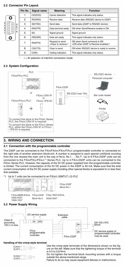
FX2N-232IF RS232C INTERFACE BLOCK
HARDWARE MANUAL
JY992D73501D
This manual contains text, diagrams and explanations which will guide the reader in the correct installationand operation of the FX2N-232IF RS232C Interface Block. It should be read and understood beforeattempting to install or use the unit. Further information can be found in the FX PROGRAMMING MAN-UAL, FX series hardware manuals.
If in doubt at any stage during the installation of the FX2N-232IF RS232C Interface Block always consult aprofessional electrical engineer who is qualified and trained to the local and national standards.
1. INTRODUCTION
The RS232C interface block FX2N-232IF (hereinafter referred to as "232IF") is connected to the FX2N/FX2NC/FX3U/FX3UC series PLC to realize full duplex serial data communication with another RS232Cinterface such as a personal computer, bar code reader, printer, etc.
1) Two or more devices with RS232C interfaces can be connected to an FX2N/FX2NC/FX3U/FX3UC seriesPLC by using the RS232C special function block. Up to 8 special function block can be connected tothe FX2N/FX3U/FX3UC*1 series PLC. Up to 4 special function block can be connected to the FX2NC
PLC. (Refer to section 2.1)
2) Communication requires no protocolFull-duplex asynchronous communication between RS232C devices is specified through buffer mem-ory (BFM). The FROM/TO instruction is used for the buffer memory.
3) The send/receive buffer can accommodate 512 bytes/256 words.When the RS232C interlink connection mode is used, data exceeding 512 bytes/256 words can alsocan be received.
4) ASCII/HEX conversion functionThe function to convert and send and a hexadecimal numeric (0 to F) saved in the send data buffer aswell as the function to convert a received ASCII code into a hexadecimal numeric (0 to F) and save itto the receive buffer are provided.
*1 Up to 7 special function block can be connected to the FX3UC-32MT-LT (-2) PLC
2. Specifications
2.1 External Dimensions and Part Names
Dimensions:mm(inches) Weight: Approx. 0.3 kg Accessory:Special block No. label
➀
!
"
#
$%&$'
(
➁
➂ ➃ ➄
➉
➅
➈
➆
➇
Extension cable
Mounting hole (2-φ4.5(0.18"))
POWER LED :Lit when both the 5V DC power supplied from the main unit and the 24V DC powersupplied from the external terminal are supplied.
SD LED:Lit while data is sent to the RS232C equipment connected to the 232IF.
RD LED:Lit while data is received from the RS232C equipment connected to the 232IF.
Terminal screws (M3 (0.12"))
Next step extension connector
RS232C connector (9-pin D-SUB connector: #4-40unc inch screw thread)
DIN rail clip
DIN rail groove (35(1.38"))
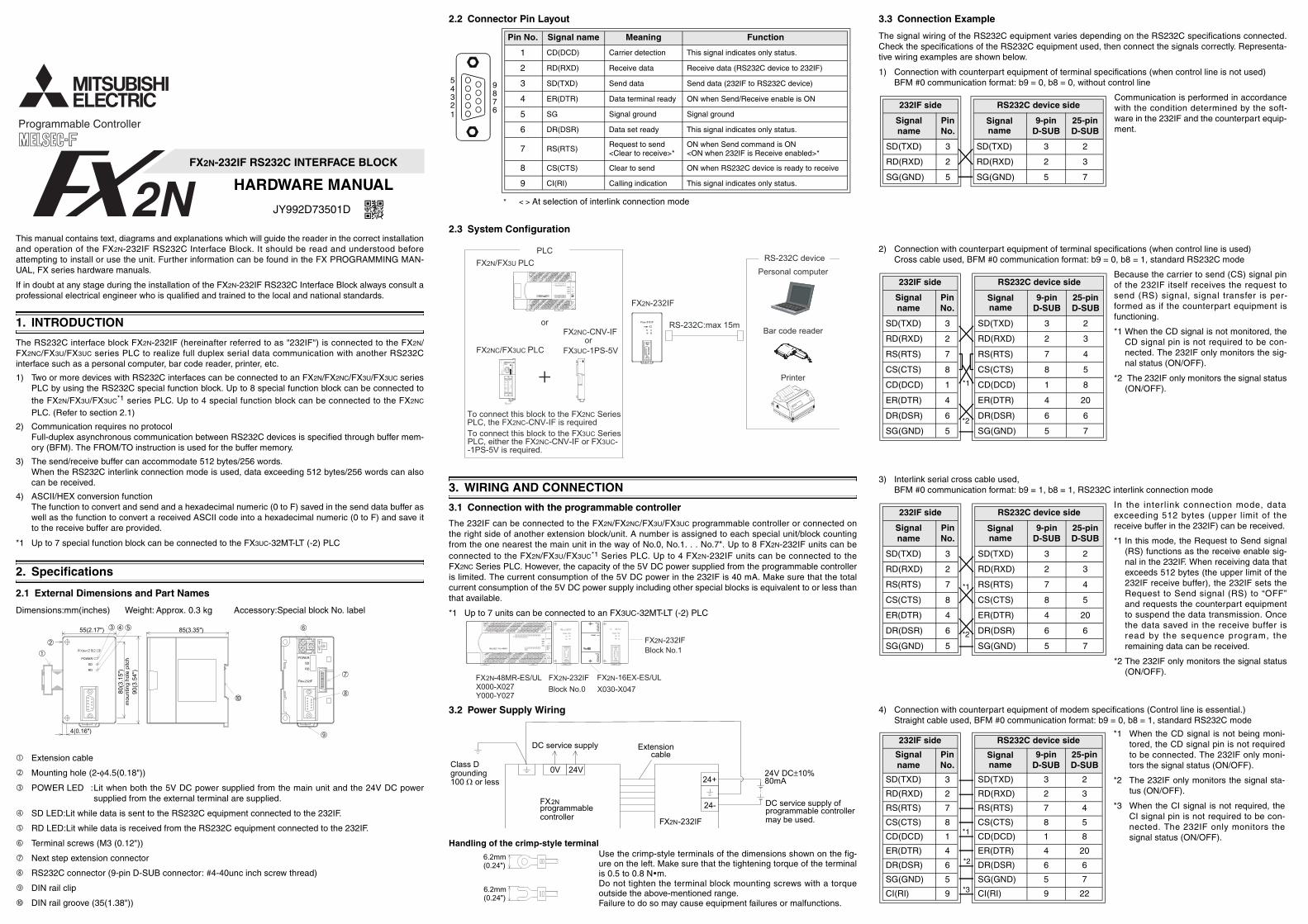
2.2 Connector Pin Layout
12345
9876
* < > At selection of interlink connection mode
Pin No. Signal name Meaning Function
1 CD(DCD) Carrier detection This signal indicates only status.
2 RD(RXD) Receive data Receive data (RS232C device to 232IF)
3 SD(TXD) Send data Send data (232IF to RS232C device)
4 ER(DTR) Data terminal ready ON when Send/Receive enable is ON
5 SG Signal ground Signal ground
6 DR(DSR) Data set ready This signal indicates only status.
7 RS(RTS)Request to send<Clear to receive>*
ON when Send command is ON<ON when 232IF is Receive enabled>*
8 CS(CTS) Clear to send ON when RS232C device is ready to receive
9 CI(RI) Calling indication This signal indicates only status.
2.3 System Configuration
RS-232C device
Personal computer
Bar code reader
Printer
FX2N-232IF
RS-232C:max 15mPOWER
SD
RD
PLC
FX2N/FX3U PLC
FX2NC/FX3UC PLC
To connect this block to the FX2NC SeriesPLC, the FX2NC-CNV-IF is required
orFX2NC-CNV-IF
To connect this block to the FX3UC SeriesPLC, either the FX2NC-CNV-IF or FX3UC--1PS-5V is required.
FX3UC-1PS-5V
or
3. WIRING AND CONNECTION
3.1 Connection with the programmable controller
The 232IF can be connected to the FX2N/FX2NC/FX3U/FX3UC programmable controller or connected onthe right side of another extension block/unit. A number is assigned to each special unit/block countingfrom the one nearest the main unit in the way of No.0, No.1. . . No.7". Up to 8 FX2N-232IF units can beconnected to the FX2N/FX3U/FX3UC*1 Series PLC. Up to 4 FX2N-232IF units can be connected to theFX2NC Series PLC. However, the capacity of the 5V DC power supplied from the programmable controlleris limited. The current consumption of the 5V DC power in the 232IF is 40 mA. Make sure that the totalcurrent consumption of the 5V DC power supply including other special blocks is equivalent to or less thanthat available.
*1 Up to 7 units can be connected to an FX3UC-32MT-LT (-2) PLC
3.2 Power Supply Wiring
Handling of the crimp-style terminalUse the crimp-style terminals of the dimensions shown on the fig-ure on the left. Make sure that the tightening torque of the terminalis 0.5 to 0.8 N m.Do not tighten the terminal block mounting screws with a torqueoutside the above-mentioned range.Failure to do so may cause equipment failures or malfunctions.
FX2Nprogrammablecontroller
Extensioncable
FX2N-232IF
DC service supply ofprogrammable controllermay be used.
DC service supply
Class D grounding100 Ω or less
24V DC±10%80mA24+
24-
0V 24V
#
#
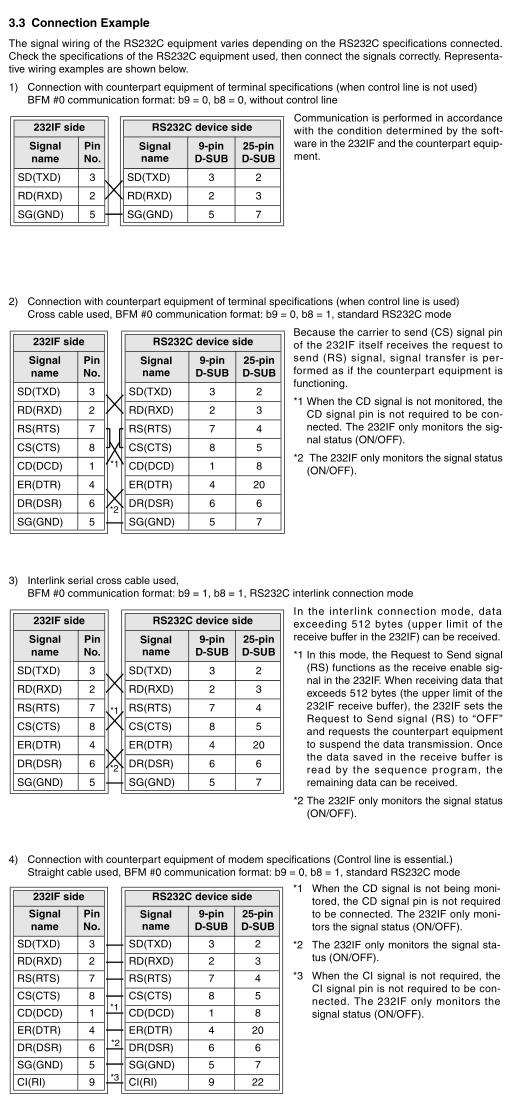
3.3 Connection Example
The signal wiring of the RS232C equipment varies depending on the RS232C specifications connected.Check the specifications of the RS232C equipment used, then connect the signals correctly. Representa-tive wiring examples are shown below.
1) Connection with counterpart equipment of terminal specifications (when control line is not used)BFM #0 communication format: b9 = 0, b8 = 0, without control line
Communication is performed in accordancewith the condition determined by the soft-ware in the 232IF and the counterpart equip-ment.
232IF side
Signalname
PinNo.
SD(TXD) 3
RD(RXD) 2
SG(GND) 5
RS232C device side
Signalname
9-pinD-SUB
25-pinD-SUB
SD(TXD) 3 2
RD(RXD) 2 3
SG(GND) 5 7
2) Connection with counterpart equipment of terminal specifications (when control line is used)Cross cable used, BFM #0 communication format: b9 = 0, b8 = 1, standard RS232C mode
Because the carrier to send (CS) signal pinof the 232IF itself receives the request tosend (RS) signal, signal transfer is per-formed as if the counterpart equipment isfunctioning.
*1 When the CD signal is not monitored, theCD signal pin is not required to be con-nected. The 232IF only monitors the sig-nal status (ON/OFF).
*2 The 232IF only monitors the signal status(ON/OFF).
232IF side
Signalname
PinNo.
SD(TXD) 3
RD(RXD) 2
RS(RTS) 7
CS(CTS) 8
CD(DCD) 1
ER(DTR) 4
DR(DSR) 6
SG(GND) 5
RS232C device side
Signalname
9-pinD-SUB
25-pinD-SUB
SD(TXD) 3 2
RD(RXD) 2 3
RS(RTS) 7 4
CS(CTS) 8 5
CD(DCD) 1 8
ER(DTR) 4 20
DR(DSR) 6 6
SG(GND) 5 7
*1
*2
3) Interlink serial cross cable used, BFM #0 communication format: b9 = 1, b8 = 1, RS232C interlink connection mode
In the interl ink connection mode, dataexceeding 512 bytes (upper limit of thereceive buffer in the 232IF) can be received.
*1 In this mode, the Request to Send signal(RS) functions as the receive enable sig-nal in the 232IF. When receiving data thatexceeds 512 bytes (the upper limit of the232IF receive buffer), the 232IF sets theRequest to Send signal (RS) to “OFF”and requests the counterpart equipmentto suspend the data transmission. Oncethe data saved in the receive buffer isread by the sequence program, theremaining data can be received.
*2 The 232IF only monitors the signal status(ON/OFF).
232IF side
Signalname
PinNo.
SD(TXD) 3
RD(RXD) 2
RS(RTS) 7
CS(CTS) 8
ER(DTR) 4
DR(DSR) 6
SG(GND) 5
RS232C device side
Signalname
9-pinD-SUB
25-pinD-SUB
SD(TXD) 3 2
RD(RXD) 2 3
RS(RTS) 7 4
CS(CTS) 8 5
ER(DTR) 4 20
DR(DSR) 6 6
SG(GND) 5 7
*1
*2
4) Connection with counterpart equipment of modem specifications (Control line is essential.)Straight cable used, BFM #0 communication format: b9 = 0, b8 = 1, standard RS232C mode
232IF side
Signalname
PinNo.
SD(TXD) 3
RD(RXD) 2
RS(RTS) 7
CS(CTS) 8
CD(DCD) 1
ER(DTR) 4
DR(DSR) 6
SG(GND) 5
CI(RI) 9
RS232C device side
Signalname
9-pinD-SUB
25-pinD-SUB
SD(TXD) 3 2
RD(RXD) 2 3
RS(RTS) 7 4
CS(CTS) 8 5
CD(DCD) 1 8
ER(DTR) 4 20
DR(DSR) 6 6
SG(GND) 5 7
CI(RI) 9 22
*1 When the CD signal is not being moni-tored, the CD signal pin is not requiredto be connected. The 232IF only moni-tors the signal status (ON/OFF).
*2 The 232IF only monitors the signal sta-tus (ON/OFF).
*3 When the CI signal is not required, theCI signal pin is not required to be con-nected. The 232IF only monitors thesignal status (ON/OFF).
*1
*2
*3
FX2N-232IF RS232C INTERFACE BLOCK
HARDWARE MANUAL
JY992D73501D
This manual contains text, diagrams and explanations which will guide the reader in the correct installationand operation of the FX2N-232IF RS232C Interface Block. It should be read and understood beforeattempting to install or use the unit. Further information can be found in the FX PROGRAMMING MAN-UAL, FX series hardware manuals.
If in doubt at any stage during the installation of the FX2N-232IF RS232C Interface Block always consult aprofessional electrical engineer who is qualified and trained to the local and national standards.
1. INTRODUCTION
The RS232C interface block FX2N-232IF (hereinafter referred to as "232IF") is connected to the FX2N/FX2NC/FX3U/FX3UC series PLC to realize full duplex serial data communication with another RS232Cinterface such as a personal computer, bar code reader, printer, etc.
1) Two or more devices with RS232C interfaces can be connected to an FX2N/FX2NC/FX3U/FX3UC seriesPLC by using the RS232C special function block. Up to 8 special function block can be connected tothe FX2N/FX3U/FX3UC*1 series PLC. Up to 4 special function block can be connected to the FX2NC
PLC. (Refer to section 2.1)
2) Communication requires no protocolFull-duplex asynchronous communication between RS232C devices is specified through buffer mem-ory (BFM). The FROM/TO instruction is used for the buffer memory.
3) The send/receive buffer can accommodate 512 bytes/256 words.When the RS232C interlink connection mode is used, data exceeding 512 bytes/256 words can alsocan be received.
4) ASCII/HEX conversion functionThe function to convert and send and a hexadecimal numeric (0 to F) saved in the send data buffer aswell as the function to convert a received ASCII code into a hexadecimal numeric (0 to F) and save itto the receive buffer are provided.
*1 Up to 7 special function block can be connected to the FX3UC-32MT-LT (-2) PLC
2. Specifications
2.1 External Dimensions and Part Names
Dimensions:mm(inches) Weight: Approx. 0.3 kg Accessory:Special block No. label
➀
!
"
#
$%&$'
(
➁
➂ ➃ ➄
➉
➅
➈
➆
➇
Extension cable
Mounting hole (2-φ4.5(0.18"))
POWER LED :Lit when both the 5V DC power supplied from the main unit and the 24V DC powersupplied from the external terminal are supplied.
SD LED:Lit while data is sent to the RS232C equipment connected to the 232IF.
RD LED:Lit while data is received from the RS232C equipment connected to the 232IF.
Terminal screws (M3 (0.12"))
Next step extension connector
RS232C connector (9-pin D-SUB connector: #4-40unc inch screw thread)
DIN rail clip
DIN rail groove (35(1.38"))
2.2 Connector Pin Layout
12345
9876
* < > At selection of interlink connection mode
Pin No. Signal name Meaning Function
1 CD(DCD) Carrier detection This signal indicates only status.
2 RD(RXD) Receive data Receive data (RS232C device to 232IF)
3 SD(TXD) Send data Send data (232IF to RS232C device)
4 ER(DTR) Data terminal ready ON when Send/Receive enable is ON
5 SG Signal ground Signal ground
6 DR(DSR) Data set ready This signal indicates only status.
7 RS(RTS)Request to send<Clear to receive>*
ON when Send command is ON<ON when 232IF is Receive enabled>*
8 CS(CTS) Clear to send ON when RS232C device is ready to receive
9 CI(RI) Calling indication This signal indicates only status.
2.3 System Configuration
RS-232C device
Personal computer
Bar code reader
Printer
FX2N-232IF
RS-232C:max 15mPOWER
SD
RD
PLC
FX2N/FX3U PLC
FX2NC/FX3UC PLC
To connect this block to the FX2NC SeriesPLC, the FX2NC-CNV-IF is required
orFX2NC-CNV-IF
To connect this block to the FX3UC SeriesPLC, either the FX2NC-CNV-IF or FX3UC--1PS-5V is required.
FX3UC-1PS-5V
or
3. WIRING AND CONNECTION
3.1 Connection with the programmable controller
The 232IF can be connected to the FX2N/FX2NC/FX3U/FX3UC programmable controller or connected onthe right side of another extension block/unit. A number is assigned to each special unit/block countingfrom the one nearest the main unit in the way of No.0, No.1. . . No.7". Up to 8 FX2N-232IF units can beconnected to the FX2N/FX3U/FX3UC*1 Series PLC. Up to 4 FX2N-232IF units can be connected to theFX2NC Series PLC. However, the capacity of the 5V DC power supplied from the programmable controlleris limited. The current consumption of the 5V DC power in the 232IF is 40 mA. Make sure that the totalcurrent consumption of the 5V DC power supply including other special blocks is equivalent to or less thanthat available.
*1 Up to 7 units can be connected to an FX3UC-32MT-LT (-2) PLC
3.2 Power Supply Wiring
Handling of the crimp-style terminalUse the crimp-style terminals of the dimensions shown on the fig-ure on the left. Make sure that the tightening torque of the terminalis 0.5 to 0.8 N m.Do not tighten the terminal block mounting screws with a torqueoutside the above-mentioned range.Failure to do so may cause equipment failures or malfunctions.
FX2Nprogrammablecontroller
Extensioncable
FX2N-232IF
DC service supply ofprogrammable controllermay be used.
DC service supply
Class D grounding100 Ω or less
24V DC±10%80mA24+
24-
0V 24V
#
#
3.3 Connection Example
The signal wiring of the RS232C equipment varies depending on the RS232C specifications connected.Check the specifications of the RS232C equipment used, then connect the signals correctly. Representa-tive wiring examples are shown below.
1) Connection with counterpart equipment of terminal specifications (when control line is not used)BFM #0 communication format: b9 = 0, b8 = 0, without control line
Communication is performed in accordancewith the condition determined by the soft-ware in the 232IF and the counterpart equip-ment.
232IF side
Signalname
PinNo.
SD(TXD) 3
RD(RXD) 2
SG(GND) 5
RS232C device side
Signalname
9-pinD-SUB
25-pinD-SUB
SD(TXD) 3 2
RD(RXD) 2 3
SG(GND) 5 7
2) Connection with counterpart equipment of terminal specifications (when control line is used)Cross cable used, BFM #0 communication format: b9 = 0, b8 = 1, standard RS232C mode
Because the carrier to send (CS) signal pinof the 232IF itself receives the request tosend (RS) signal, signal transfer is per-formed as if the counterpart equipment isfunctioning.
*1 When the CD signal is not monitored, theCD signal pin is not required to be con-nected. The 232IF only monitors the sig-nal status (ON/OFF).
*2 The 232IF only monitors the signal status(ON/OFF).
232IF side
Signalname
PinNo.
SD(TXD) 3
RD(RXD) 2
RS(RTS) 7
CS(CTS) 8
CD(DCD) 1
ER(DTR) 4
DR(DSR) 6
SG(GND) 5
RS232C device side
Signalname
9-pinD-SUB
25-pinD-SUB
SD(TXD) 3 2
RD(RXD) 2 3
RS(RTS) 7 4
CS(CTS) 8 5
CD(DCD) 1 8
ER(DTR) 4 20
DR(DSR) 6 6
SG(GND) 5 7
*1
*2
3) Interlink serial cross cable used, BFM #0 communication format: b9 = 1, b8 = 1, RS232C interlink connection mode
In the interl ink connection mode, dataexceeding 512 bytes (upper limit of thereceive buffer in the 232IF) can be received.
*1 In this mode, the Request to Send signal(RS) functions as the receive enable sig-nal in the 232IF. When receiving data thatexceeds 512 bytes (the upper limit of the232IF receive buffer), the 232IF sets theRequest to Send signal (RS) to “OFF”and requests the counterpart equipmentto suspend the data transmission. Oncethe data saved in the receive buffer isread by the sequence program, theremaining data can be received.
*2 The 232IF only monitors the signal status(ON/OFF).
232IF side
Signalname
PinNo.
SD(TXD) 3
RD(RXD) 2
RS(RTS) 7
CS(CTS) 8
ER(DTR) 4
DR(DSR) 6
SG(GND) 5
RS232C device side
Signalname
9-pinD-SUB
25-pinD-SUB
SD(TXD) 3 2
RD(RXD) 2 3
RS(RTS) 7 4
CS(CTS) 8 5
ER(DTR) 4 20
DR(DSR) 6 6
SG(GND) 5 7
*1
*2
4) Connection with counterpart equipment of modem specifications (Control line is essential.)Straight cable used, BFM #0 communication format: b9 = 0, b8 = 1, standard RS232C mode
232IF side
Signalname
PinNo.
SD(TXD) 3
RD(RXD) 2
RS(RTS) 7
CS(CTS) 8
CD(DCD) 1
ER(DTR) 4
DR(DSR) 6
SG(GND) 5
CI(RI) 9
RS232C device side
Signalname
9-pinD-SUB
25-pinD-SUB
SD(TXD) 3 2
RD(RXD) 2 3
RS(RTS) 7 4
CS(CTS) 8 5
CD(DCD) 1 8
ER(DTR) 4 20
DR(DSR) 6 6
SG(GND) 5 7
CI(RI) 9 22
*1 When the CD signal is not being moni-tored, the CD signal pin is not requiredto be connected. The 232IF only moni-tors the signal status (ON/OFF).
*2 The 232IF only monitors the signal sta-tus (ON/OFF).
*3 When the CI signal is not required, theCI signal pin is not required to be con-nected. The 232IF only monitors thesignal status (ON/OFF).
*1
*2
*3

manual confers no industrial property rights or any rights of any other kind, nor does it r any patent licenses. Mitsubishi Electric Corporation cannot be held responsible for any ems involving industrial property rights which may occur as a result of using the contents in this manual.
For safe use product has been manufactured as a general-purpose part for general industries, and has een designed or manufactured to be incorporated in a device or system used in purposes
ed to human life.re using the product for special purposes such as nuclear power, electric power, space, medicine or passenger movement vehicles, consult with Mitsubishi Electric. product has been manufactured under strict quality control. However when installing the uct where major accidents or losses could occur if the product fails, install appropriate up or failsafe functions in the system.
ntyion of loss in opportunity and secondary loss from warranty liabilityless of the gratis warranty term, Mitsubishi shall not be liable for compensation to:ages caused by any cause found not to be the responsibility of Mitsubishi.
s in opportunity, lost profits incurred to the user by Failures of Mitsubishi products.cial damages and secondary damages whether foreseeable or not, compensation for idents, and compensation for damages to products other than Mitsubishi products.lacement by the user, maintenance of on-site equipment, start-up test run and other tasks.
HEAD OFFICE : TOKYO BUILDING, 2-7-3 MARUNOUCHI, CHIYODA-KU, TOKYO 100-8310, JAPAN
Note: This symbol mark is for China only.
有有害6物质的名称,含有量,含有部品
器电子产品有害物质限制使用标识要求」的表示方式
产品中所含有的有害6物质的名称,含有量,含有部品如下表所示。
产品中有害物质的名称及含量
表格依据SJ/T 11364的规定编制。
:表示该有害物质在该部件所有均质材料中的含量均在GB/T 26572规定的限量要
表示该有害物质至少在该部件的某一均质材料中的含量超出GB/T 26572规定的
部件名称
有害物质
铅(Pb)
汞(Hg)
六价铬(Cr(VI))
二苯醚PBDE)
编程控制器外壳
印刷基板 ×
镉(Cd)
e
er
C
RRT
-du
00
tt o
FX
ion
a
e
lie
rre
rov
r
or
) rre
r a t
e at
p
of
Manual number : JY992D73501
Manual revision : D
Date : September 2017
1DEffective September 2017Specifications are subject to change without notice
Guidelines for the safety of the user and protection of the FX2N-232IF RS232C INTERFACE BLOCK
• This manual has been written to be used by trained and competent personnel. This is definedby the European directives for machinery, low voltage and EMC.
• If in doubt at any stage during the installation of the FX2N-232IF always consult a professionalelectrical engineer who is qualified and trained to the local and national standards. If in doubtabout the operation or use of the FX2N-232IF please consult the nearest Mitsubishi Electricdistributor.
Under no circumstances will Mitsubishi Electric be liable or responsible for any consequentialdamage that may arise as a result of the installation or use of this equipment.
All examples and diagrams shown in this manual are intended only as an aid to understand-ing the text, not to guarantee operation. Mitsubishi Electric will accept no responsibility foractual use of the product based on these illustrative examples.
Owing to the very great variety in possible application of this equipment, you must satisfyyourself as to its suitability for your specific application.
JY992D7350
5. DIAGNOSTICS
For error code, refer to the FX Communication User’s M
1) Check the status of the POWER LED provided in th
- When it is lit, the drive power is correctly supp
- If it is extinguished, supply the drive power co
2) Check the status of the SD LED and the RD LED p
- If the RD LED is not lit while data is received ocheck the instruction and the wiring.
- When the RD LED is lit while data is receivedtion and the wiring are correct.
3) Make sure that the communication setting (BFM #0equipment. If they are not equivalent each other, co
4) Verify the status of the data send/receive device. Foment is ready to receive before starting to send dat
5) When the terminator is not used, check whether thable data capacity. Use the terminator, if the send d
6) Make sure that the external equipment is correctly o
7) Check whether the type of send data and the type make them equivalent.
nual.
232IF.
d.
ctly.
ided in the 232IF.
the SD LED is not lighted while data is sent,
the SD LED is lit while data is sent, the installa-
of the 232IF is equivalent to that of the externalct as required.
example, make sure that the counterpart equip-o it.
send data capacity is equivalent to the accept-a capacity may be changed.
erating.
receive data are equivalent. If they are different,
This confeproblnoted
Thisnot brelatBefoaeroThisprodback
WarraExclusRegard(1) Dam(2) Los(3) Spe
acc(4) Rep
4. SPECIFICATIONS
4.1 General specifications
4.2 Power Supply Specifications
General specifications excluding withstand voltag
Withstand voltage
Internal power supply from programmable controll
External power supply
4.3 Specifications
Item
Transmission Standard Conforming RS232
Transmission distance Max. 15m
Connected the number 1:1
Connector 9-pin D-SUB type
Pin layout of connector1:CD(DCD), 2:RD(6:DR(DSR), 7:RS(
Indication (LED) POWER, SD, RD
Communication method No protocol by full
Sported baud rate 300, 600, 1200, 24
Isolation Photo-coupler
Number of I/O points occupied8 points taken from(can be either inpu
Applicable programmablecontrollers
FX2N/FX2NC/FX3U/
Communication with program-mable controller
FROM/TO instruct
含
「电
本
本
×:
可
Same as those of the main unit
500V AC, 1 minute (between the entire external terminal and the ground terminal)
5V DC 40mA
24V DC ± 10% 80mA
Content
XD), 3:SD(TXD), 4:ER(DTR), 5:SG, S), 8:CS(CTS), 9:CI(RI)
plex asynchronous
, 4800, 9600, 19200
he programmable controller extension bus r output)
3UC series
求以下。
限量要求。
多溴联苯(PBB)
多溴(
•
•
•

This manual confers no industrial property rights or any rights of any other kind, nor does it confer any patent licenses. Mitsubishi Electric Corporation cannot be held responsible for any problems involving industrial property rights which may occur as a result of using the contents noted in this manual.
For safe useThis product has been manufactured as a general-purpose part for general industries, and has not been designed or manufactured to be incorporated in a device or system used in purposes related to human life.Before using the product for special purposes such as nuclear power, electric power, aerospace, medicine or passenger movement vehicles, consult with Mitsubishi Electric.This product has been manufactured under strict quality control. However when installing the product where major accidents or losses could occur if the product fails, install appropriate backup or failsafe functions in the system.
WarrantyExclusion of loss in opportunity and secondary loss from warranty liabilityRegardless of the gratis warranty term, Mitsubishi shall not be liable for compensation to:(1) Damages caused by any cause found not to be the responsibility of Mitsubishi.(2) Loss in opportunity, lost profits incurred to the user by Failures of Mitsubishi products.(3) Special damages and secondary damages whether foreseeable or not, compensation for
accidents, and compensation for damages to products other than Mitsubishi products.(4) Replacement by the user, maintenance of on-site equipment, start-up test run and other tasks.
HEAD OFFICE : TOKYO BUILDING, 2-7-3 MARUNOUCHI, CHIYODA-KU, TOKYO 100-8310, JAPAN
Note: This symbol mark is for China only.
含有有害6物质的名称,含有量,含有部品
「电器电子产品有害物质限制使用标识要求」的表示方式
本产品中所含有的有害6物质的名称,含有量,含有部品如下表所示。
产品中有害物质的名称及含量
本表格依据SJ/T 11364的规定编制。
:表示该有害物质在该部件所有均质材料中的含量均在GB/T 26572规定的限量要求以下。
×:表示该有害物质至少在该部件的某一均质材料中的含量超出GB/T 26572规定的限量要求。
部件名称
有害物质
铅(Pb)
汞(Hg)
六价铬(Cr(VI))
多溴联苯(PBB)
多溴二苯醚(PBDE)
可编程控制器外壳
印刷基板 ×
镉(Cd)
4. SPECIFICATIONS
4.1 General specifications
4.2 Power Supply Specifications
General specifications excluding withstand voltage Same as those of the main unit
Withstand voltage500V AC, 1 minute (between the entire external terminal and the ground terminal)
Internal power supply from programmable controller 5V DC 40mA
External power supply 24V DC ± 10% 80mA
4.3 Specifications
Item Content
Transmission Standard Conforming RS232C
Transmission distance Max. 15m
Connected the number 1:1
Connector 9-pin D-SUB type
Pin layout of connector1:CD(DCD), 2:RD(RXD), 3:SD(TXD), 4:ER(DTR), 5:SG, 6:DR(DSR), 7:RS(RTS), 8:CS(CTS), 9:CI(RI)
Indication (LED) POWER, SD, RD
Communication method No protocol by full-duplex asynchronous
Sported baud rate 300, 600, 1200, 2400, 4800, 9600, 19200
Isolation Photo-coupler
Number of I/O points occupied8 points taken from the programmable controller extension bus (can be either input or output)
Applicable programmablecontrollers
FX2N/FX2NC/FX3U/FX3UC series
Communication with program-mable controller
FROM/TO instruction
5. DIAGNOSTICS
For error code, refer to the FX Communication User’s Manual.
1) Check the status of the POWER LED provided in the 232IF.
- When it is lit, the drive power is correctly supplied.
- If it is extinguished, supply the drive power correctly.
2) Check the status of the SD LED and the RD LED provided in the 232IF.
- If the RD LED is not lit while data is received or the SD LED is not lighted while data is sent, check the instruction and the wiring.
- When the RD LED is lit while data is received or the SD LED is lit while data is sent, the installa-tion and the wiring are correct.
3) Make sure that the communication setting (BFM #0) of the 232IF is equivalent to that of the externalequipment. If they are not equivalent each other, correct as required.
4) Verify the status of the data send/receive device. For example, make sure that the counterpart equip-ment is ready to receive before starting to send data to it.
5) When the terminator is not used, check whether the send data capacity is equivalent to the accept-able data capacity. Use the terminator, if the send data capacity may be changed.
6) Make sure that the external equipment is correctly operating.
7) Check whether the type of send data and the type of receive data are equivalent. If they are different,make them equivalent.
Manual number : JY992D73501
Manual revision : D
Date : September 2017
JY992D73501DEffective September 2017Specifications are subject to change without notice
Guidelines for the safety of the user and protection of the FX2N-232IF RS232C INTERFACE BLOCK
• This manual has been written to be used by trained and competent personnel. This is definedby the European directives for machinery, low voltage and EMC.
• If in doubt at any stage during the installation of the FX2N-232IF always consult a professionalelectrical engineer who is qualified and trained to the local and national standards. If in doubtabout the operation or use of the FX2N-232IF please consult the nearest Mitsubishi Electricdistributor.
• Under no circumstances will Mitsubishi Electric be liable or responsible for any consequentialdamage that may arise as a result of the installation or use of this equipment.
• All examples and diagrams shown in this manual are intended only as an aid to understand-ing the text, not to guarantee operation. Mitsubishi Electric will accept no responsibility foractual use of the product based on these illustrative examples.
• Owing to the very great variety in possible application of this equipment, you must satisfyyourself as to its suitability for your specific application.
FX2N-232IF RS232C INTERFACE BLOCK
HARDWARE MANUAL
JY992D73501D
This manual contains text, diagrams and explanations which will guide the reader in the correct installationand operation of the FX2N-232IF RS232C Interface Block. It should be read and understood beforeattempting to install or use the unit. Further information can be found in the FX PROGRAMMING MAN-UAL, FX series hardware manuals.
If in doubt at any stage during the installation of the FX2N-232IF RS232C Interface Block always consult aprofessional electrical engineer who is qualified and trained to the local and national standards.
1. INTRODUCTION
The RS232C interface block FX2N-232IF (hereinafter referred to as "232IF") is connected to the FX2N/FX2NC/FX3U/FX3UC series PLC to realize full duplex serial data communication with another RS232Cinterface such as a personal computer, bar code reader, printer, etc.
1) Two or more devices with RS232C interfaces can be connected to an FX2N/FX2NC/FX3U/FX3UC seriesPLC by using the RS232C special function block. Up to 8 special function block can be connected tothe FX2N/FX3U/FX3UC*1 series PLC. Up to 4 special function block can be connected to the FX2NC
PLC. (Refer to section 2.1)
2) Communication requires no protocolFull-duplex asynchronous communication between RS232C devices is specified through buffer mem-ory (BFM). The FROM/TO instruction is used for the buffer memory.
3) The send/receive buffer can accommodate 512 bytes/256 words.When the RS232C interlink connection mode is used, data exceeding 512 bytes/256 words can alsocan be received.
4) ASCII/HEX conversion functionThe function to convert and send and a hexadecimal numeric (0 to F) saved in the send data buffer aswell as the function to convert a received ASCII code into a hexadecimal numeric (0 to F) and save itto the receive buffer are provided.
*1 Up to 7 special function block can be connected to the FX3UC-32MT-LT (-2) PLC
2. Specifications
2.1 External Dimensions and Part Names
Dimensions:mm(inches) Weight: Approx. 0.3 kg Accessory:Special block No. label
➀
!
"
#
$%&$'
(
➁
➂ ➃ ➄
➉
➅
➈
➆
➇
Extension cable
Mounting hole (2-φ4.5(0.18"))
POWER LED :Lit when both the 5V DC power supplied from the main unit and the 24V DC powersupplied from the external terminal are supplied.
SD LED:Lit while data is sent to the RS232C equipment connected to the 232IF.
RD LED:Lit while data is received from the RS232C equipment connected to the 232IF.
Terminal screws (M3 (0.12"))
Next step extension connector
RS232C connector (9-pin D-SUB connector: #4-40unc inch screw thread)
DIN rail clip
DIN rail groove (35(1.38"))
2.2 Connector Pin Layout
12345
9876
* < > At selection of interlink connection mode
Pin No. Signal name Meaning Function
1 CD(DCD) Carrier detection This signal indicates only status.
2 RD(RXD) Receive data Receive data (RS232C device to 232IF)
3 SD(TXD) Send data Send data (232IF to RS232C device)
4 ER(DTR) Data terminal ready ON when Send/Receive enable is ON
5 SG Signal ground Signal ground
6 DR(DSR) Data set ready This signal indicates only status.
7 RS(RTS)Request to send<Clear to receive>*
ON when Send command is ON<ON when 232IF is Receive enabled>*
8 CS(CTS) Clear to send ON when RS232C device is ready to receive
9 CI(RI) Calling indication This signal indicates only status.
2.3 System Configuration
RS-232C device
Personal computer
Bar code reader
Printer
FX2N-232IF
RS-232C:max 15mPOWER
SD
RD
PLC
FX2N/FX3U PLC
FX2NC/FX3UC PLC
To connect this block to the FX2NC SeriesPLC, the FX2NC-CNV-IF is required
orFX2NC-CNV-IF
To connect this block to the FX3UC SeriesPLC, either the FX2NC-CNV-IF or FX3UC--1PS-5V is required.
FX3UC-1PS-5V
or
3. WIRING AND CONNECTION
3.1 Connection with the programmable controller
The 232IF can be connected to the FX2N/FX2NC/FX3U/FX3UC programmable controller or connected onthe right side of another extension block/unit. A number is assigned to each special unit/block countingfrom the one nearest the main unit in the way of No.0, No.1. . . No.7". Up to 8 FX2N-232IF units can beconnected to the FX2N/FX3U/FX3UC*1 Series PLC. Up to 4 FX2N-232IF units can be connected to theFX2NC Series PLC. However, the capacity of the 5V DC power supplied from the programmable controlleris limited. The current consumption of the 5V DC power in the 232IF is 40 mA. Make sure that the totalcurrent consumption of the 5V DC power supply including other special blocks is equivalent to or less thanthat available.
*1 Up to 7 units can be connected to an FX3UC-32MT-LT (-2) PLC
3.2 Power Supply Wiring
Handling of the crimp-style terminalUse the crimp-style terminals of the dimensions shown on the fig-ure on the left. Make sure that the tightening torque of the terminalis 0.5 to 0.8 N m.Do not tighten the terminal block mounting screws with a torqueoutside the above-mentioned range.Failure to do so may cause equipment failures or malfunctions.
FX2Nprogrammablecontroller
Extensioncable
FX2N-232IF
DC service supply ofprogrammable controllermay be used.
DC service supply
Class D grounding100 Ω or less
24V DC±10%80mA24+
24-
0V 24V
#
#
3.3 Connection Example
The signal wiring of the RS232C equipment varies depending on the RS232C specifications connected.Check the specifications of the RS232C equipment used, then connect the signals correctly. Representa-tive wiring examples are shown below.
1) Connection with counterpart equipment of terminal specifications (when control line is not used)BFM #0 communication format: b9 = 0, b8 = 0, without control line
Communication is performed in accordancewith the condition determined by the soft-ware in the 232IF and the counterpart equip-ment.
232IF side
Signalname
PinNo.
SD(TXD) 3
RD(RXD) 2
SG(GND) 5
RS232C device side
Signalname
9-pinD-SUB
25-pinD-SUB
SD(TXD) 3 2
RD(RXD) 2 3
SG(GND) 5 7
2) Connection with counterpart equipment of terminal specifications (when control line is used)Cross cable used, BFM #0 communication format: b9 = 0, b8 = 1, standard RS232C mode
Because the carrier to send (CS) signal pinof the 232IF itself receives the request tosend (RS) signal, signal transfer is per-formed as if the counterpart equipment isfunctioning.
*1 When the CD signal is not monitored, theCD signal pin is not required to be con-nected. The 232IF only monitors the sig-nal status (ON/OFF).
*2 The 232IF only monitors the signal status(ON/OFF).
232IF side
Signalname
PinNo.
SD(TXD) 3
RD(RXD) 2
RS(RTS) 7
CS(CTS) 8
CD(DCD) 1
ER(DTR) 4
DR(DSR) 6
SG(GND) 5
RS232C device side
Signalname
9-pinD-SUB
25-pinD-SUB
SD(TXD) 3 2
RD(RXD) 2 3
RS(RTS) 7 4
CS(CTS) 8 5
CD(DCD) 1 8
ER(DTR) 4 20
DR(DSR) 6 6
SG(GND) 5 7
*1
*2
3) Interlink serial cross cable used, BFM #0 communication format: b9 = 1, b8 = 1, RS232C interlink connection mode
In the interl ink connection mode, dataexceeding 512 bytes (upper limit of thereceive buffer in the 232IF) can be received.
*1 In this mode, the Request to Send signal(RS) functions as the receive enable sig-nal in the 232IF. When receiving data thatexceeds 512 bytes (the upper limit of the232IF receive buffer), the 232IF sets theRequest to Send signal (RS) to “OFF”and requests the counterpart equipmentto suspend the data transmission. Oncethe data saved in the receive buffer isread by the sequence program, theremaining data can be received.
*2 The 232IF only monitors the signal status(ON/OFF).
232IF side
Signalname
PinNo.
SD(TXD) 3
RD(RXD) 2
RS(RTS) 7
CS(CTS) 8
ER(DTR) 4
DR(DSR) 6
SG(GND) 5
RS232C device side
Signalname
9-pinD-SUB
25-pinD-SUB
SD(TXD) 3 2
RD(RXD) 2 3
RS(RTS) 7 4
CS(CTS) 8 5
ER(DTR) 4 20
DR(DSR) 6 6
SG(GND) 5 7
*1
*2
4) Connection with counterpart equipment of modem specifications (Control line is essential.)Straight cable used, BFM #0 communication format: b9 = 0, b8 = 1, standard RS232C mode
232IF side
Signalname
PinNo.
SD(TXD) 3
RD(RXD) 2
RS(RTS) 7
CS(CTS) 8
CD(DCD) 1
ER(DTR) 4
DR(DSR) 6
SG(GND) 5
CI(RI) 9
RS232C device side
Signalname
9-pinD-SUB
25-pinD-SUB
SD(TXD) 3 2
RD(RXD) 2 3
RS(RTS) 7 4
CS(CTS) 8 5
CD(DCD) 1 8
ER(DTR) 4 20
DR(DSR) 6 6
SG(GND) 5 7
CI(RI) 9 22
*1 When the CD signal is not being moni-tored, the CD signal pin is not requiredto be connected. The 232IF only moni-tors the signal status (ON/OFF).
*2 The 232IF only monitors the signal sta-tus (ON/OFF).
*3 When the CI signal is not required, theCI signal pin is not required to be con-nected. The 232IF only monitors thesignal status (ON/OFF).
*1
*2
*3
This manual confers no industrial property rights or any rights of any other kind, nor does it confer any patent licenses. Mitsubishi Electric Corporation cannot be held responsible for any problems involving industrial property rights which may occur as a result of using the contents noted in this manual.
For safe useThis product has been manufactured as a general-purpose part for general industries, and has not been designed or manufactured to be incorporated in a device or system used in purposes related to human life.Before using the product for special purposes such as nuclear power, electric power, aerospace, medicine or passenger movement vehicles, consult with Mitsubishi Electric.This product has been manufactured under strict quality control. However when installing the product where major accidents or losses could occur if the product fails, install appropriate backup or failsafe functions in the system.
WarrantyExclusion of loss in opportunity and secondary loss from warranty liabilityRegardless of the gratis warranty term, Mitsubishi shall not be liable for compensation to:(1) Damages caused by any cause found not to be the responsibility of Mitsubishi.(2) Loss in opportunity, lost profits incurred to the user by Failures of Mitsubishi products.(3) Special damages and secondary damages whether foreseeable or not, compensation for
accidents, and compensation for damages to products other than Mitsubishi products.(4) Replacement by the user, maintenance of on-site equipment, start-up test run and other tasks.
HEAD OFFICE : TOKYO BUILDING, 2-7-3 MARUNOUCHI, CHIYODA-KU, TOKYO 100-8310, JAPAN
Note: This symbol mark is for China only.
含有有害6物质的名称,含有量,含有部品
「电器电子产品有害物质限制使用标识要求」的表示方式
本产品中所含有的有害6物质的名称,含有量,含有部品如下表所示。
产品中有害物质的名称及含量
本表格依据SJ/T 11364的规定编制。
:表示该有害物质在该部件所有均质材料中的含量均在GB/T 26572规定的限量要求以下。
×:表示该有害物质至少在该部件的某一均质材料中的含量超出GB/T 26572规定的限量要求。
部件名称
有害物质
铅(Pb)
汞(Hg)
六价铬(Cr(VI))
多溴联苯(PBB)
多溴二苯醚(PBDE)
可编程控制器外壳
印刷基板 ×
镉(Cd)
4. SPECIFICATIONS
4.1 General specifications
4.2 Power Supply Specifications
General specifications excluding withstand voltage Same as those of the main unit
Withstand voltage500V AC, 1 minute (between the entire external terminal and the ground terminal)
Internal power supply from programmable controller 5V DC 40mA
External power supply 24V DC ± 10% 80mA
4.3 Specifications
Item Content
Transmission Standard Conforming RS232C
Transmission distance Max. 15m
Connected the number 1:1
Connector 9-pin D-SUB type
Pin layout of connector1:CD(DCD), 2:RD(RXD), 3:SD(TXD), 4:ER(DTR), 5:SG, 6:DR(DSR), 7:RS(RTS), 8:CS(CTS), 9:CI(RI)
Indication (LED) POWER, SD, RD
Communication method No protocol by full-duplex asynchronous
Sported baud rate 300, 600, 1200, 2400, 4800, 9600, 19200
Isolation Photo-coupler
Number of I/O points occupied8 points taken from the programmable controller extension bus (can be either input or output)
Applicable programmablecontrollers
FX2N/FX2NC/FX3U/FX3UC series
Communication with program-mable controller
FROM/TO instruction
5. DIAGNOSTICS
For error code, refer to the FX Communication User’s Manual.
1) Check the status of the POWER LED provided in the 232IF.
- When it is lit, the drive power is correctly supplied.
- If it is extinguished, supply the drive power correctly.
2) Check the status of the SD LED and the RD LED provided in the 232IF.
- If the RD LED is not lit while data is received or the SD LED is not lighted while data is sent, check the instruction and the wiring.
- When the RD LED is lit while data is received or the SD LED is lit while data is sent, the installa-tion and the wiring are correct.
3) Make sure that the communication setting (BFM #0) of the 232IF is equivalent to that of the externalequipment. If they are not equivalent each other, correct as required.
4) Verify the status of the data send/receive device. For example, make sure that the counterpart equip-ment is ready to receive before starting to send data to it.
5) When the terminator is not used, check whether the send data capacity is equivalent to the accept-able data capacity. Use the terminator, if the send data capacity may be changed.
6) Make sure that the external equipment is correctly operating.
7) Check whether the type of send data and the type of receive data are equivalent. If they are different,make them equivalent.
Manual number : JY992D73501
Manual revision : D
Date : September 2017
JY992D73501DEffective September 2017Specifications are subject to change without notice
Guidelines for the safety of the user and protection of the FX2N-232IF RS232C INTERFACE BLOCK
• This manual has been written to be used by trained and competent personnel. This is definedby the European directives for machinery, low voltage and EMC.
• If in doubt at any stage during the installation of the FX2N-232IF always consult a professionalelectrical engineer who is qualified and trained to the local and national standards. If in doubtabout the operation or use of the FX2N-232IF please consult the nearest Mitsubishi Electricdistributor.
• Under no circumstances will Mitsubishi Electric be liable or responsible for any consequentialdamage that may arise as a result of the installation or use of this equipment.
• All examples and diagrams shown in this manual are intended only as an aid to understand-ing the text, not to guarantee operation. Mitsubishi Electric will accept no responsibility foractual use of the product based on these illustrative examples.
• Owing to the very great variety in possible application of this equipment, you must satisfyyourself as to its suitability for your specific application.


![三菱シーケンサ テクニカルニュース [ 1 /13 ]...09M104 FX2N-485-BD 09S305 FX3U-485-BD FX3U, FX3UC-32MT-LT(-2)に接続可 09M105 FX 2N -422-BD 09S306 FX 3U -422-BD](https://img.pdfslide.net/doc/110x75/5ecf91e971116727190a35b6/eff-ffffff-1-13-09m104-fx2n-485-bd.jpg)