Embed Size (px)
Citation preview
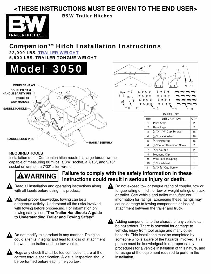
FIGURE F1: Underside view of Coupler Head
VIEW77
B&W Trailer Hitches
Companion™ Hitch Installation Instructions22,000 LBS. TRAILER WEIGHT5,500 LBS. TRAILER TONGUE WEIGHT
Model 3050
WARNING Failure to comply with the safety information in these instructions could result in serious injury or death.
Read all installation and operating instructions along with all labels before using this product.
Without proper knowledge, towing can be a dangerous activity. Understand all the risks involved with towing before proceeding. For information on towing safety, see "The Trailer Handbook: A guide to Understanding Trailer and Towing Safety"
Do not modify this product in any manner. Doing so could alter its integrity and lead to a loss of attachmentbetween the trailer and the tow vehicle.
Regularly check that all bolted connections are at the correct torque specification. A visual inspection shouldbe performed before each time you tow.
Do not exceed tow or tongue rating of coupler, tow or tongue rating of hitch, or tow or weight ratings of truck or trailer. See vehicle and trailer manufacturer information for ratings. Exceeding these ratings may cause damage to towing components or loss of attachment between the trailer and truck.
Adding components to the chassis of any vehicle can be hazardous. There is potential for damage to vehicle, injury from tool usage and many other hazards. This installation must be completed by someone who is aware of the hazards involved. This person must be knowledgeable of proper safety procedures for a vehicle installation of this nature, andfor usage of the equipment required to perform the installation.
Approximately 15%−25% of the trailer weight should be on the hitch.
WARNING: Do not use the Companion 5th wheel hitch with any device that changes the location of the king pin pivot point. The king pin on your trailer must rotate in the jaws of the Companion Coupler, see figure F1. Preventing the king pin from rotating within the jaws of the Companion Coupler with a wedge,see figure F2, or any other device, such as a Reese Sidewinder or Reese Revolution , could result inproperty damage, serious injury or death.
Copyright 2015, B&W Custom Truck Beds, Inc. ALL RIGHTS RESERVED RVK3050 08 24 2015
REQUIRED TOOLSInstallation of the Companion hitch requires a large torque wrench capable of measuring 80 ft−lbs, a 3/4" socket, a 7/16", and 9/16" socket or wrench, a 7/32" allen wrench.
ATTACHING TRAILERRemove the coupler cam handle safety pin and use the cam handle to open the coupler jaws. Adjust the height of the 5th wheel trailer so that the king pinplate is slightly lower than the top of the coupler. Back the truck towards the trailer, centering the trailer’s king pin in the coupler, until the king pin has engaged the jaws. Ensure that the coupler cam handle has completely closed before inserting the cam handle safety pin through the cam handle and the coupler. Hook up brake and lighting connectionsbefore towing.
PULL TESTHave the truck stationary with the emergency brake on, the trailer wheels blocked and landing gear still resting firm on the ground supporting the weight of the trailer. Make sure no one is between the truck and trailer, return to the cab of the truck. Release theemergency brake and apply the trailer brakes. Try to pull the trailer forward with the truck. If the trailer is properly hooked up, the wheel blocks and trailer brakes should not allow the truck to move forward. If trailer is not hitched correctly, the trailer will separatefrom the truck. However, with the landing gear resting firmly on the ground, it will support the trailer and not allow it to drop or fall on the truck sides.
UNATTACHING TRAILERLower landing gear and block the trailer wheels. Raise the trailer until the tongue weight is removed from the truck. Then, unpin the Coupler handle and rotate to the open position to unlatch the jaws. If the jaws do not open, readjusting the landing gear may relieve pressure and allow them to open. Use thesafety pin to lock the handle in the open position andwhen you are sure that the landing gear will support the trailer, move the truck forward to release the jaws from the kingpin. The jaws will always open when the pressure of the trailer is taken off the Coupler as the truck pulls away.
UNINSTALL HITCHTo uninstall the Companion hitch, remove theSaddle lock pins, grab the saddle handles and lift toremove the Coupler from the pivot arms. To remove the Companion base, loosen the draw down bolt andretract the Turnoverball gooseneck latch pin handle all the way out. Carefully lift and position the Companion base out of the Gooseneck hitch socket.
Lubricate top surface of coupler with automotive typechassis grease or use a nylon lube plate to provide alubricated surface.
Allow adequate clearance between the bed side and the underside of the front of the trailer for pitch and roll of the trailer.
The height of the king pin box and pivot arms shouldbe adjusted so that the trailer is approximately level for towing. Grease the saddle through
the grease zerk approximatelyevery six months withmulti−purpose grease. This allows the coupler to pivot freely, see figure F1.
Grease jaws with automotivetype chassis grease.
The Companion was designed to be used with the Turnoverball™ mounting system. Other uses will void the warranty and are expressly prohibited by B&W Trailer Hitches.
HELPFUL TIPS:
® ®
Reese is a registered trademark of Cequent Performance Products.®
NOTICE: All bolted connections should be checked for the correct torque specification regularly. A visual inspection should be performed before each time you tow.
<THESE INSTRUCTIONS MUST BE GIVEN TO THE END USER>
FIGURE F1:Top view of coupler head.
FIGURE F2:Coupler Head with
locking wedge.
PARTS LIST
QTYDESCRIPTIONITEM
2Pivot Arms1
2Base Legs2
1612" X 1−1
2" Cap Screws3
1612" Lock Washer4
1612" Finish Nut5
238" Button Head Cap Screw6
238" Lock Nut7
1Mounting Clip8
1Wire Torsion Spring9
114" Finish Nut10
114" X 1 2" Cap Screw11
GREASE ZERK
KING PINPIVOT POINT
WEDGE
2 17
6
9
8 11
10
5 4 3
BASE ASSEMBLY
SADDLE HANDLE
COUPLERCAM HANDLE
COUPLER CAMHANDLE SAFETY PIN
COUPLER JAWS
SADDLE LOCK PINS
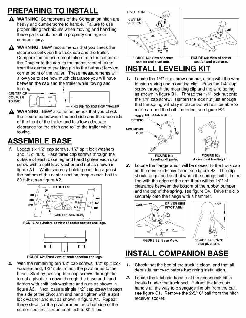
PREPARING TO INSTALLWARNING: Components of the Companion hitch are heavy and cumbersome to handle. Failure to use proper lifting techniques when moving and handling these parts could result in property damage or serious injury.
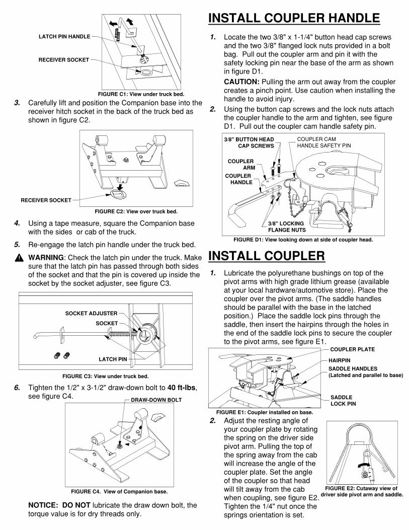
Tighten the 1/2" x 3−1/2" draw−down bolt to 40 ft−lbs, see figure C4.
WARNING: Check the latch pin under the truck. Make sure that the latch pin has passed through both sides of the socket and that the pin is covered up inside the socket by the socket adjuster, see figure C3.
Using a tape measure, square the Companion base with the sides or cab of the truck.
Carefully lift and position the Companion base into the receiver hitch socket in the back of the truck bed as shown in figure C2.
Re−engage the latch pin handle under the truck bed.
NOTICE: DO NOT lubricate the draw down bolt, the torque value is for dry threads only.
WARNING: B&W also recommends that you check the clearance between the bed side and the undersideof the front of the trailer and to allow adequate clearance for the pitch and roll of the trailer while towing.
WARNING: B&W recommends that you check the clearance between the truck cab and the trailer. Compare the measurement taken from the center of the Coupler to the cab, to the measurement taken from the center of the king pin to the farthest forward corner point of the trailer. These measurements will allow you to see how much clearance you will have between the cab and the trailer while towing and turning.
3.
4.
5.
6.
ASSEMBLE BASELocate six 1/2" cap screws, 1/2" split lock washers and, 1/2" nuts. Pass three cap screws through the outside of each base leg and hand tighten each cap screw with a split lock washer and nut as shown in figure A1. While securely holding each leg against the bottom of the center section, torque each bolt to 80 ft−lbs, see figure A2.
1.
INSTALL COUPLER HANDLE1. Locate the two 3/8" x 1−1/4" button head cap screws
and the two 3/8" flanged lock nuts provided in a bolt bag. Pull out the coupler arm and pin it with the safety locking pin near the base of the arm as shown in figure D1.CAUTION: Pulling the arm out away from the coupler creates a pinch point. Use caution when installing the handle to avoid injury.Using the button cap screws and the lock nuts attach the coupler handle to the arm and tighten, see figure D1. Pull out the coupler cam handle safety pin.
2.
INSTALL COUPLER1. Lubricate the polyurethane bushings on top of the
pivot arms with high grade lithium grease (available at your local hardware/automotive store). Place the coupler over the pivot arms. (The saddle handles should be parallel with the base in the latched position.) Place the saddle lock pins through thesaddle, then insert the hairpins through the holes in the end of the saddle lock pins to secure the coupler to the pivot arms, see figure E1.
2. Adjust the resting angle of your coupler plate by rotatingthe spring on the driver side pivot arm. Pulling the top of the spring away from the cab will increase the angle of the coupler plate. Set the angle of the coupler so that head will tilt away from the cab when coupling, see figure E2.Tighten the 1/4" nut once the springs orientation is set.
With the remaining ten 1/2" cap screws, 1/2" split lock washers and, 1/2" nuts, attach the pivot arms to the base. Start by passing four cap screws through the top of a pivot arm down through the base and hand tighten with split lock washers and nuts as shown in figure A3. Next, pass a single 1/2" cap screw throughthe side of the pivot arm and hand tighten with a split lock washer and nut as shown in figure A4. Repeat these steps for the pivot arm on the other side of the center section. Torque each bolt to 80 ft−lbs.
2. Check that the bed of the truck is clean, and that all debris is removed before beginning installation.
Locate the latch pin handle of the gooseneck hitch located under the truck bed. Retract the latch pin handle all the way to disengage the pin from the ball, see figure C1. Remove the 2−5/16" ball from the hitch receiver socket.
2.
1.
INSTALL COMPANION BASE
INSTALL LEVELING KITLocate the 1/4" cap screw and nut, along with the wiretension spring and mounting clip. Pass the 1/4" cap screw through the mounting clip and the wire spring as shown in figure B1. Thread the 1/4" lock nut onto the 1/4" cap screw. Tighten the lock nut just enough that the spring will stay in place but will still be able to rotate around the bolt if needed, see figure B2.
Locate the flange which will be closest to the truck cabon the driver side pivot arm, see figure B3. The clip should be placed so that when the springs coil is in theline with the edge of the arm there will be 1/2" of clearance between the bottom of the rubber bumper and the top of the spring, see figure B4. Drive the clip securely onto the flange with a hammer.
2.
1.
FIGURE A1: Underside view of center section and legs.
FIGURE A3: View of centersection and pivot arm.
FIGURE A4: View of centersection and pivot arm.
FIGURE C2: View over truck bed.
FIGURE C4. View of Companion base.
FIGURE A2: Front view of center section and legs.
FIGURE C1: View under truck bed.
FIGURE C3: View under truck bed.
FIGURE D1: View looking down at side of coupler head.
FIGURE E1: Coupler installed on base.
FIGURE E2: Cutaway view of driver side pivot arm and saddle.
FIGURE B4: Driver side pivot arm.
FIGURE B2:Assembled leveling kit.
FIGURE B1: Leveling kit parts.
FIGURE B3: Base View.
CENTER OF COUPLERTO CAB
KING PIN TO EDGE OF TRAILER
CENTER SECTION
BASE LEG
PIVOT ARM
CENTERSECTION LATCH PIN HANDLE
RECEIVER SOCKET
SOCKET ADJUSTER
LATCH PIN
DRAW−DOWN BOLT
SOCKET
3/8" BUTTON HEADCAP SCREWS
COUPLER HANDLE
COUPLER CAM HANDLE SAFETY PIN
COUPLER ARM
3/8" LOCKINGFLANGE NUTS
COUPLER PLATE
SADDLELOCK PIN
HAIRPIN
SADDLE HANDLES(Latched and parallel to base)
1/2"
WIRESPRING
1/4" LOCK NUT
MOUNTINGCLIP
DRIVER SIDEPIVOT ARM
CAB
RECEIVER SOCKET
PREPARING TO INSTALLWARNING: Components of the Companion hitch areheavy and cumbersome to handle. Failure to use proper lifting techniques when moving and handlingthese parts could result in property damage or serious injury.
Tighten the 1/2" x 3−1/2" draw−down bolt to 40 ft−lbs, see figure C4.
WARNING: Check the latch pin under the truck. Make sure that the latch pin has passed through both sides of the socket and that the pin is covered up inside the socket by the socket adjuster, see figure C3.
Using a tape measure, square the Companion base with the sides or cab of the truck.
Carefully lift and position the Companion base into the receiver hitch socket in the back of the truck bed as shown in figure C2.
Re−engage the latch pin handle under the truck bed.
NOTICE: DO NOT lubricate the draw down bolt, the torque value is for dry threads only.
WARNING: B&W also recommends that you check the clearance between the bed side and the undersideof the front of the trailer and to allow adequate clearance for the pitch and roll of the trailer while towing.
WARNING: B&W recommends that you check the clearance between the truck cab and the trailer. Compare the measurement taken from the center of the Coupler to the cab, to the measurement taken from the center of the king pin to the farthest forwardcorner point of the trailer. These measurements will allow you to see how much clearance you will have between the cab and the trailer while towing and turning.
3.
4.
5.
6.
ASSEMBLE BASELocate six 1/2" cap screws, 1/2" split lock washersand, 1/2" nuts. Pass three cap screws through the outside of each base leg and hand tighten each cap screw with a split lock washer and nut as shown in figure A1. While securely holding each leg against the bottom of the center section, torque each bolt to 80 ft−lbs, see figure A2.
1.
INSTALL COUPLER HANDLE1. Locate the two 3/8" x 1−1/4" button head cap screws
and the two 3/8" flanged lock nuts provided in a boltbag. Pull out the coupler arm and pin it with thesafety locking pin near the base of the arm as shownin figure D1.CAUTION: Pulling the arm out away from the couplercreates a pinch point. Use caution when installing thehandle to avoid injury.Using the button cap screws and the lock nuts attachthe coupler handle to the arm and tighten, see figureD1. Pull out the coupler cam handle safety pin.
2.
INSTALL COUPLER1. Lubricate the polyurethane bushings on top of the
pivot arms with high grade lithium grease (availableat your local hardware/automotive store). Place thecoupler over the pivot arms. (The saddle handlesshould be parallel with the base in the latchedposition.) Place the saddle lock pins through thesaddle, then insert the hairpins through the holes inthe end of the saddle lock pins to secure the couplerto the pivot arms, see figure E1.
2. Adjust the resting angle ofyour coupler plate by rotatingthe spring on the driver sidepivot arm. Pulling the top ofthe spring away from the cabwill increase the angle of thecoupler plate. Set the angleof the coupler so that headwill tilt away from the cabwhen coupling, see figure E2.Tighten the 1/4" nut once thesprings orientation is set.
With the remaining ten 1/2" cap screws, 1/2" split lock washers and, 1/2" nuts, attach the pivot arms to the base. Start by passing four cap screws through the top of a pivot arm down through the base and hand tighten with split lock washers and nuts as shown in figure A3. Next, pass a single 1/2" cap screw throughthe side of the pivot arm and hand tighten with a split lock washer and nut as shown in figure A4. Repeat these steps for the pivot arm on the other side of the center section. Torque each bolt to 80 ft−lbs.
2. Check that the bed of the truck is clean, and that all debris is removed before beginning installation.
Locate the latch pin handle of the gooseneck hitch located under the truck bed. Retract the latch pinhandle all the way to disengage the pin from the ball, see figure C1. Remove the 2−5/16" ball from the hitch receiver socket.
2.
1.
INSTALL COMPANION BASE
INSTALL LEVELING KITLocate the 1/4" cap screw and nut, along with the wiretension spring and mounting clip. Pass the 1/4" cap screw through the mounting clip and the wire spring as shown in figure B1. Thread the 1/4" lock nut ontothe 1/4" cap screw. Tighten the lock nut just enough that the spring will stay in place but will still be able to rotate around the bolt if needed, see figure B2.
Locate the flange which will be closest to the truck cabon the driver side pivot arm, see figure B3. The clip should be placed so that when the springs coil is in theline with the edge of the arm there will be 1/2" ofclearance between the bottom of the rubber bumper and the top of the spring, see figure B4. Drive the clip securely onto the flange with a hammer.
2.
1.
FIGURE A1: Underside view of center section and legs.
FIGURE A3: View of centersection and pivot arm.
FIGURE A4: View of centersection and pivot arm.
FIGURE C2: View over truck bed.
FIGURE C4. View of Companion base.
FIGURE A2: Front view of center section and legs.
FIGURE C1: View under truck bed.
FIGURE C3: View under truck bed.
FIGURE D1: View looking down at side of coupler head.
FIGURE E1: Coupler installed on base.
FIGURE E2: Cutaway view of driver side pivot arm and saddle.
FIGURE B4: Driver side pivot arm.
FIGURE B2:Assembled leveling kit.
FIGURE B1: Leveling kit parts.
FIGURE B3: Base View.
CENTER OF COUPLERTO CAB
KING PIN TO EDGE OF TRAILER
CENTER SECTION
BASE LEG
PIVOT ARM
CENTERSECTION LATCH PIN HANDLE
RECEIVER SOCKET
SOCKET ADJUSTER
LATCH PIN
DRAW−DOWN BOLT
SOCKET
3/8" BUTTON HEADCAP SCREWS
COUPLER HANDLE
COUPLER CAM HANDLE SAFETY PIN
COUPLER ARM
3/8" LOCKINGFLANGE NUTS
COUPLER PLATE
SADDLELOCK PIN
HAIRPIN
SADDLE HANDLES(Latched and parallel to base)
1/2"
WIRESPRING
1/4" LOCK NUT
MOUNTINGCLIP
DRIVER SIDEPIVOT ARM
CAB
RECEIVER SOCKET
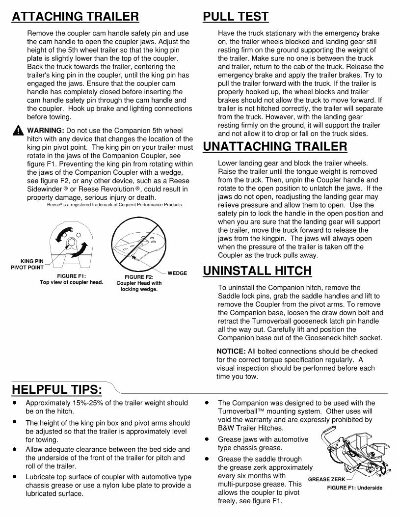
FIGURE F1: Underside
Regularly check that all bolted connections are at the correct torque specification. A visual inspection shouldbe performed before each time you tow.
procedures for a vehicle installation of this nature, andfor usage of the equipment required to perform the installation.
Approximately 15%−25% of the trailer weight should be on the hitch.
WARNING: Do not use the Companion 5th wheel hitch with any device that changes the location of the king pin pivot point. The king pin on your trailer must rotate in the jaws of the Companion Coupler, see figure F1. Preventing the king pin from rotating within the jaws of the Companion Coupler with a wedge, see figure F2, or any other device, such as a Reese Sidewinder or Reese Revolution , could result in property damage, serious injury or death.
ATTACHING TRAILERRemove the coupler cam handle safety pin and use the cam handle to open the coupler jaws. Adjust the height of the 5th wheel trailer so that the king pin plate is slightly lower than the top of the coupler. Back the truck towards the trailer, centering the trailer’s king pin in the coupler, until the king pin has engaged the jaws. Ensure that the coupler cam handle has completely closed before inserting the cam handle safety pin through the cam handle and the coupler. Hook up brake and lighting connectionsbefore towing.
PULL TESTHave the truck stationary with the emergency brake on, the trailer wheels blocked and landing gear still resting firm on the ground supporting the weight of the trailer. Make sure no one is between the truck and trailer, return to the cab of the truck. Release theemergency brake and apply the trailer brakes. Try to pull the trailer forward with the truck. If the trailer is properly hooked up, the wheel blocks and trailer brakes should not allow the truck to move forward. If trailer is not hitched correctly, the trailer will separatefrom the truck. However, with the landing gear resting firmly on the ground, it will support the trailer and not allow it to drop or fall on the truck sides.
UNATTACHING TRAILERLower landing gear and block the trailer wheels. Raise the trailer until the tongue weight is removed from the truck. Then, unpin the Coupler handle and rotate to the open position to unlatch the jaws. If the jaws do not open, readjusting the landing gear may relieve pressure and allow them to open. Use the safety pin to lock the handle in the open position andwhen you are sure that the landing gear will support the trailer, move the truck forward to release the jaws from the kingpin. The jaws will always open when the pressure of the trailer is taken off the Coupler as the truck pulls away.
UNINSTALL HITCHTo uninstall the Companion hitch, remove the Saddle lock pins, grab the saddle handles and lift to remove the Coupler from the pivot arms. To remove the Companion base, loosen the draw down bolt andretract the Turnoverball gooseneck latch pin handle all the way out. Carefully lift and position the Companion base out of the Gooseneck hitch socket.
Lubricate top surface of coupler with automotive typechassis grease or use a nylon lube plate to provide alubricated surface.
Allow adequate clearance between the bed side and the underside of the front of the trailer for pitch and roll of the trailer.
The height of the king pin box and pivot arms should be adjusted so that the trailer is approximately level for towing. Grease the saddle through
the grease zerk approximatelyevery six months with multi−purpose grease. This allows the coupler to pivot freely, see figure F1.
Grease jaws with automotivetype chassis grease.
The Companion was designed to be used with the Turnoverball™ mounting system. Other uses will void the warranty and are expressly prohibited by B&W Trailer Hitches.
HELPFUL TIPS:
® ®
Reese is a registered trademark of Cequent Performance Products.®
NOTICE: All bolted connections should be checked for the correct torque specification regularly. A visual inspection should be performed before each time you tow.
FIGURE F1:Top view of coupler head.
FIGURE F2:Coupler Head with
locking wedge.
GREASE ZERK
KING PINPIVOT POINT
WEDGE
![TRAILERING AND TOWING GUIDE - Chevrolet...TRAILERING AND TOWING GUIDE [SILVERADO 1500] MAX TRAILER WEIGHT RATING (LBS.) Actual weights of these items may vary. 3,500 lbs.: Dirt Bikes](https://img.pdfslide.net/doc/110x75/5e686379a6a6cd4f260a49db/trailering-and-towing-guide-chevrolet-trailering-and-towing-guide-silverado.jpg)