Embed Size (px)
Citation preview

Model 2210
User Manual
Larson•Davis Inc.1681 West 820 NorthProvo, UT 84601-1341Phone: (801) 375-0177FAX: (801) 375-0182
www.lardav.com
I2210.01 Rev. B

MODEL 2210 USER MANUAL
Copyright
Copyright 1997 by Larson•Davis, Incorporated. This manual and the software described in it are copyrighted, with all rights reserved. The manual may not be copied in whole or in part for any use without prior written consent of Larson•Davis Inc.
Disclaimer
The following paragraph does not apply in any state or country where such statements are not agreeable with local law:
Even though Larson•Davis, Inc. has reviewed its documentation, Larson•Davis Incorpo-rated makes no warranty or representation, either expressed or implied, with respect to this documentation, its quality, merchantability, or fitness for a particular purpose. This docu-mentation is subject to change without notice, and should not be construed as a commitment or representation by Larson•Davis Inc.
This publication may contain inaccuracies or typographical errors. Larson•Davis Inc. will periodically update the material for inclusion in new editions. Changes and improvements to the program described in this manual may be made at any time.
Please examine your instrument and record the following information below. You may be asked to give this information in any future communications you have with Larson•Davis, Inc.
Model 2210 Serial # ______________________
ii

SYSTEM 814 USER MANUAL
Recycling
Larson Davis, Inc. is an environmentally friendly organization and encourages our custom-ers to be environmentally conscious. When this product reaches its end of life, please recycle the product through a local recycling center or return the product to:
Larson Davis, Inc.Attn: Recycling Coordinator1681 West 820 NorthProvo, Utah, USA 84601
where it will be accepted for disposal
iii

MODEL 2210 USER MANUAL
iv
Model 2210 USER MANUAL
Table of Contents
Table of Contents ........................................................................................................ i
Chapter 1 Introduction 1-1About This Manual .................................................................................... 1-1About This Chapter .................................................................................... 1-2Formatting Conventions............................................................................. 1-2Applications ............................................................................................... 1-3Features ...................................................................................................... 1-3
Model 2210 Components....................................................................... 1-5Getting Started ........................................................................................... 1-5
Unpacking and Inspection ..................................................................... 1-6Accessories and Optional Equipment .................................................... 1-6Environmental Considerations............................................................... 1-7Data Retention ....................................................................................... 1-8
Chapter 2 Understanding the Model 2210 2-1Understanding the Model 2210 Front Panel .............................................. 2-1
LCD Display .......................................................................................... 2-3KeyPad................................................................................................... 2-5Overload Lights ..................................................................................... 2-6Ten Channel Inputs ................................................................................ 2-6
Understanding the Model 2210 Back Panel............................................... 2-7Battery Pack Compartment.................................................................... 2-8Insert Voltage Calibration ...................................................................... 2-9External Inputs ..................................................................................... 2-10Multiplexer (MUX) outputs................................................................. 2-1025-pin Signal Output Interface ............................................................ 2-11RS-232 interface .................................................................................. 2-12Fuses .................................................................................................... 2-12External Power Input ........................................................................... 2-13
Chapter 3 Setting up the Model 2210 3-1Turning on the Model 2210........................................................................ 3-1Using Menu Items ...................................................................................... 3-2
i
Model 2210 USER MANUAL
Channel .................................................................................................. 3-4Recall ..................................................................................................... 3-5Store ....................................................................................................... 3-6Overloads ............................................................................................... 3-6Mux........................................................................................................ 3-7Config .................................................................................................... 3-7
Turning off the Model 2210....................................................................... 3-8
App. A Model 2210 Specifications A-1Mechanical specifications ......................................................................... A-1Environmental Specifications ................................................................... A-1Power......................................................................................................... A-2Inputs/Outputs ........................................................................................... A-2Microphones.............................................................................................. A-4Accelerometers.......................................................................................... A-5
App. B Remote Control Commands B-1Power On/Off Commands..........................................................................B-4
M1 Command ........................................................................................B-4M2 Command ........................................................................................B-4
Condition Commands.................................................................................B-4C1 Command .........................................................................................B-4C2 Command .........................................................................................B-6C3 Command .........................................................................................B-7
Read Commands ........................................................................................B-8R1 Command .........................................................................................B-8R2 Command .........................................................................................B-9R3 Command .........................................................................................B-9R4 Command .......................................................................................B-10R5 Command .......................................................................................B-11R6 Command .......................................................................................B-13R7 Command .......................................................................................B-14R8 Command .......................................................................................B-15
Set Commands .........................................................................................B-16S1 Command........................................................................................B-17S2 Command........................................................................................B-18S3 Command........................................................................................B-19
ii

Model 2210 USER MANUAL
S4 Command........................................................................................B-21S5 Command........................................................................................B-22S6 Command........................................................................................B-23S7 Command........................................................................................B-24
Index ........................................................................................................................ I-1
iii

Model 2210 USER MANUAL
iv
C H A P T E R
1 Introduction
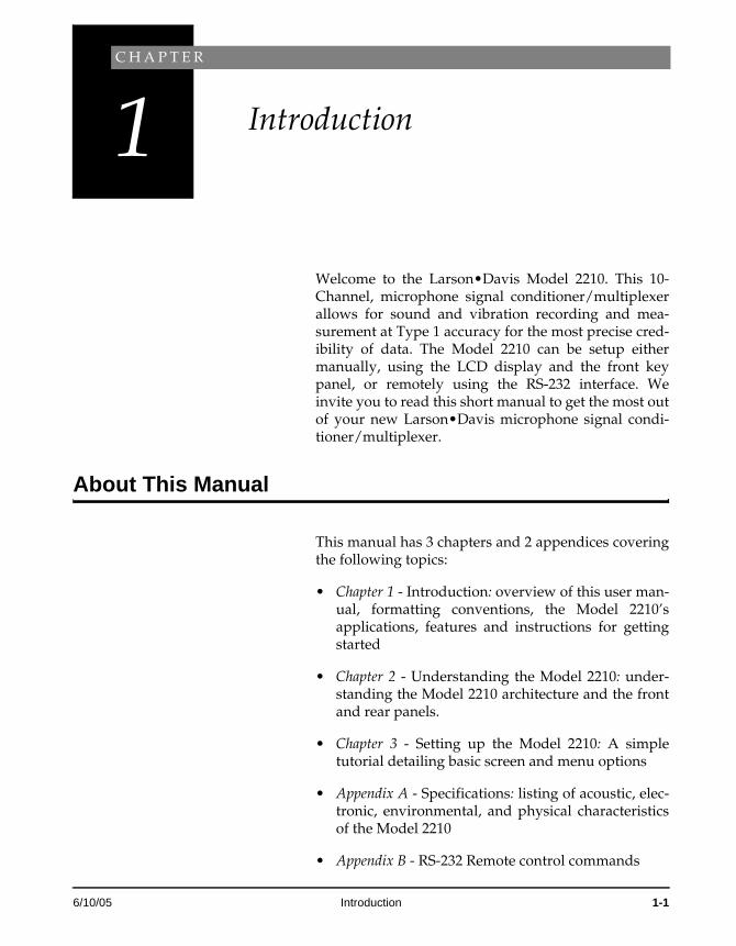
Welcome to the Larson•Davis Model 2210. This 10-Channel, microphone signal conditioner/multiplexer allows for sound and vibration recording and mea-surement at Type 1 accuracy for the most precise cred-ibility of data. The Model 2210 can be setup either manually, using the LCD display and the front key panel, or remotely using the RS-232 interface. We invite you to read this short manual to get the most out of your new Larson•Davis microphone signal condi-tioner/multiplexer.
About This Manual
This manual has 3 chapters and 2 appendices covering the following topics:
• Chapter 1 - Introduction: overview of this user man-ual, formatting conventions, the Model 2210’s applications, features and instructions for getting started
• Chapter 2 - Understanding the Model 2210: under-standing the Model 2210 architecture and the front and rear panels.
• Chapter 3 - Setting up the Model 2210: A simple tutorial detailing basic screen and menu options
• Appendix A - Specifications: listing of acoustic, elec-tronic, environmental, and physical characteristics of the Model 2210
• Appendix B - RS-232 Remote control commands
6/10/05 Introduction 1-1
About This Chapter
Specifically, this introductory chapter covers the fol-lowing topics:
• Formatting Convention: explanation of the fonts and other formatting conventions used in this man-ual
• Applications: description of the various uses of the flexible Model 2210
• Features: overview of the Model 2210’s functions and measurement capabilities
• Getting Started: instructions for unpacking, inspecting, and initially assembling the Model 2210.
Formatting Conventions
This manual uses the following formatting conven-tions:
Functions accessed by pressing a key on the Model 2210 panel are shown with an icon, for example:
Press the R [right arrow] key and then press E.
In step-by-step directions, the process (what you do) is shown in the right column, and the rationale (why you do it) with other cautions and comments are shown in the left column.
Especially important information is shown in italics, for example:
This 10-Channel, microphone signal conditioner/multi-plexer allows for sound and vibration recording and mea-
1-2 Model 2210 User Manual 6/10/05
surement at Type 1 accuracy for the most precise credibility of data.
Applications
The Larson Davis Model 2210 applications include:
• microphone signal conditioning and recording
• vibration conditioning and measurement
• multiplexer
• Computer Data Acquisition System
Features
The Larson•Davis Model 2210 meets the A, B & C weighting requirements of the American National Standards Institute (ANSI) S1.4-1983, and Interna-tional Electrotechnical Commission (IEC) 651-1979, standards for Type 1 accuracy and offers the following features:
• Adjustable gain to 42dB in 2 dB steps, selectable per channel
• Low-pass and high-pass filtering
• Weighting (A, B, & C), selectable per channel
• Battery powered
• Lightweight (2.7 kg = 6 lb) and portable [7cm x 25cm x 24.1 cm (2.75” x 10” x 9.5”) H x W x D]
• Manual or remote setup capability
• LED overload lights for each channel; can be set to either instantaneous or latching mode
• Drives microphone cables up to lengths of approxi-mately 1,000 feet
6/10/05 Introduction 1-3
• Addressable RS-232 interface
• Daisy chaining capability
• Insert voltage calibration facility
• 10 7-pin LEMO inputs for use with Larson•Davis Model PRM902 microphone pre-amplifiers and compatibles
• 1 25-pin D output with a CBL067 cable (this cable has 10 BNC connectors)
• 2 External inputs (signal conditioning optional)
• Dual multiplexer outputs, permitting use of two input channels simultaneously
• EEPROM storage capability
• Adjustable carrying handle
• 2 year warranty (see warranty statement on the copyright page at the front of this manual)
• daisy chain capability
• RS232 Interface (see appendix B)
1-4 Model 2210 User Manual 6/10/05
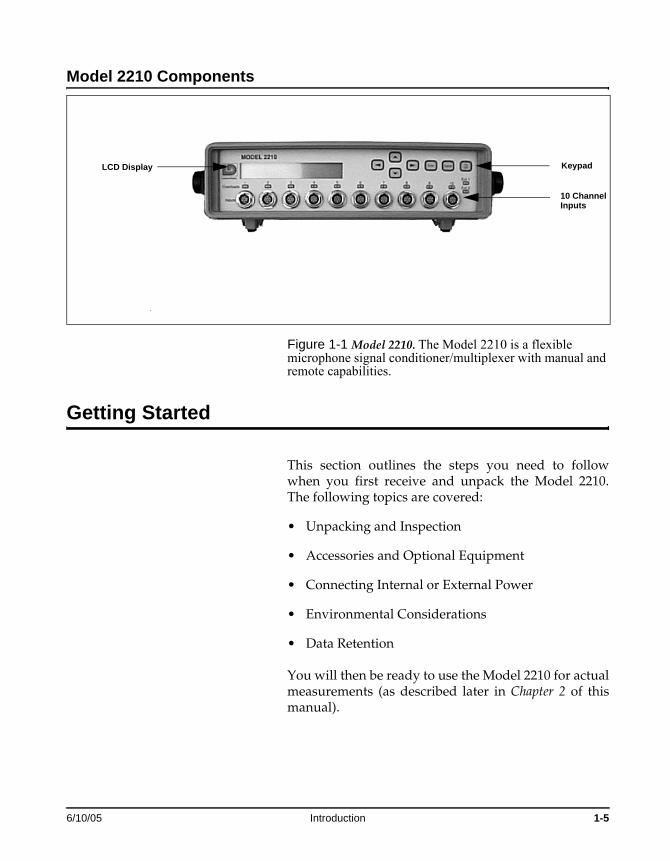
Model 2210 Components
Figure 1-1 Model 2210. The Model 2210 is a flexible microphone signal conditioner/multiplexer with manual and remote capabilities.
Getting Started
This section outlines the steps you need to follow when you first receive and unpack the Model 2210. The following topics are covered:
• Unpacking and Inspection
• Accessories and Optional Equipment
• Connecting Internal or External Power
• Environmental Considerations
• Data Retention
You will then be ready to use the Model 2210 for actual measurements (as described later in Chapter 2 of this manual).
LCD Display Keypad
10 ChannelInputs
6/10/05 Introduction 1-5
Unpacking and Inspection
Your Model 2210 has been shipped in protective pack-aging. Please verify the package contents with the fol-lowing list (Accessories and Optional Equipment) and retain the shipping containers for safe shipment at a future date. Report any damage or shortage immedi-ately to Larson•Davis, Inc. at (801)-375-0177.
If you have not already done so, please record your instrument’s serial number (located on the bottom of the 2210) and the purchase date. You will be asked to give this information in any future communications you may have with Larson•Davis, Inc.
Accessories and Optional Equipment
The Model 2210 is delivered with the following stan-dard accessories:
• Model 2210
• NiCd battery - a good NiCd battery should provide more than 6 hours of operation
• PSA004 DC Power Supply; 12 Vdc, 2 Amp 90-264 at 50-60 HZ
• CBL Output cable; 3 feet long 25-pin D connector to 10 X BNC female
• CBL045 RS-232 cable
• User manual (L•D part # I2210.01)
The following optional equipment is also available:
• Larson Davis air-condenser microphones, 1”, 1/2”, 1/4”; free-field and random
• Model PRM902 1/2” microphone pre-amplifier with 7-pin LEMO connector
1-6 Model 2210 User Manual 6/10/05

• ADP011 1/4” microphone to 1/2” pre-amplifier adapter
• PRA950 ICP accelerometer pre-amplifier
• ADP005 1/2” microphone thread to BNC adapter for use with charge-coupled accelerometers
• ADP007 1/2” microphone thread to microdot adapter for use with charge-coupled accelerometers
• EXAXXX microphone extension cable, 7-pin LEMO connectors both ends
• PSA013 External Battery Charger, powered by PSA004 DC Power Supply
• BAT007 spare NiCd rechargeable battery module
• PSA004 DC Power Supply, secondary unit for charging external battery modules while using pri-mary unit to power 2210 or charge batteries already inside 2210
• CBL049 Automobile Power Cable to power 2210 from cigarette lighter
• CBL061 BNC to mini-plug for insert voltage calibra-tion input (6 ft.)
• Spare fuses: 3A Larson•Davis 2415.0028 (Littlefuse 273-003) and 2A Larson•Davis 2415.0025 (Littlefuse 273-002)
Environmental Considerations
The Model 2210 Microphone Signal Conditioner/Mul-tiplexer can be both used and stored in a wide range of temperature, free of moisture and non-condensing humidity conditions (see “Environmental” specifica-tions in Appendix A of this manual). However, some common sense precautions should be taken. For exam-ple, allow the Model 2210 ample time to adjust to abrupt temperature changes. Condensation may form inside a cold Model 2210 if it is brought into a warm
6/10/05 Introduction 1-7
room or vehicle and may persist long after the outside case has adjusted to the ambient temperature.
Also, temperatures inside closed vehicles can reach excessive levels. Therefore, do not leave the instrument in direct sunlight in a vehicle. A simple safeguard is to keep the instrument inside a sealed foam insulated case or bag with desiccant silica gel, available at photographic equipment stores.
Data Retention
The Model 2210 has an EEPROM data retention capa-bility and will recall its previous state at power-up. Upon initial power-up the EEPROM will recall the fac-tory set-up. (Refer to “Store” in Chapter 3 on EEPROM use.)
1-8 Model 2210 User Manual 6/10/05

C H A P T E R
2 Understanding the Model 2210
This chapter covers the main architecture and compo-nents of the Model 2210. In this chapter, the following is discussed:
• Understanding the Model 2210 front panel
• Understanding the Model 2210 rear panel
Understanding the Model 2210 Front Panel
The front panel of the Model 2210 contains of the fol-lowing, each are then explained in greater detail:
• 5/8” by 3 1/2” (2 line) LCD display
• Keypad
• LED overload lights for each of the ten channel inputs
• Two LED overload lights for the two rear external inputs, (as seen in the following section)
• Ten channel inputs
4/9/99 Understanding the Model 2210 2-1
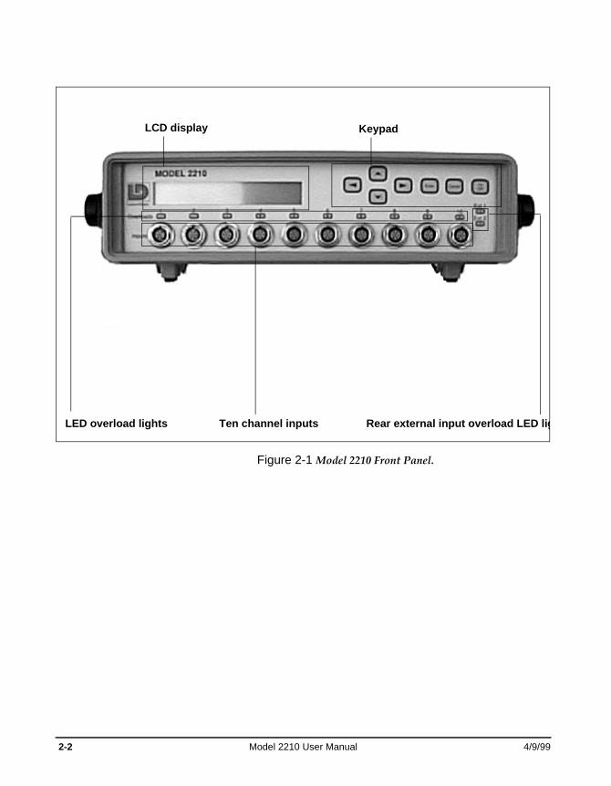
Figure 2-1 Model 2210 Front Panel.
LCD display Keypad
LED overload lights Rear external input overload LED ligTen channel inputs
2-2 Model 2210 User Manual 4/9/99
LCD Display
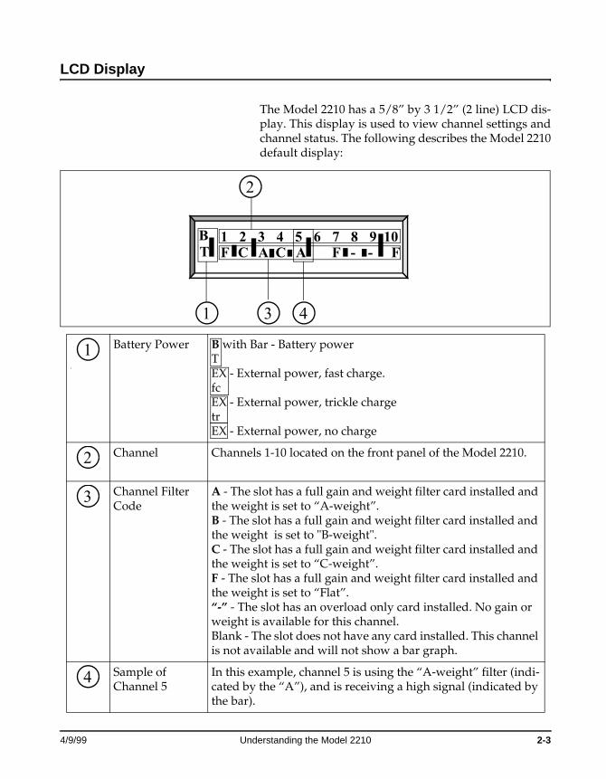
The Model 2210 has a 5/8” by 3 1/2” (2 line) LCD dis-play. This display is used to view channel settings and channel status. The following describes the Model 2210 default display:
1
Battery Power B with Bar - Battery powerTEX - External power, fast charge.fcEX - External power, trickle chargetrEX - External power, no charge
Channel Channels 1-10 located on the front panel of the Model 2210.
Channel Filter Code
A - The slot has a full gain and weight filter card installed and the weight is set to “A-weight”.B - The slot has a full gain and weight filter card installed and the weight is set to "B-weight".C - The slot has a full gain and weight filter card installed and the weight is set to “C-weight”.F - The slot has a full gain and weight filter card installed and the weight is set to “Flat”.“-” - The slot has an overload only card installed. No gain or weight is available for this channel.Blank - The slot does not have any card installed. This channel is not available and will not show a bar graph.
Sample of Channel 5
In this example, channel 5 is using the “A-weight” filter (indi-cated by the “A”), and is receiving a high signal (indicated by the bar).
1 2 3 4 5 6 7 8 9 10T F C -AB
FFC -A
1
2
3 4
1
2
3
4
4/9/99 Understanding the Model 2210 2-3
Notes on Battery Power
The 2210 measures its battery's voltage, and then converts that volt-age to time using a typical discharge curve for a 6 cell, 7.2 volt nickel cad-mium battery (Larson•Davis part # BAT007).
If the 2210 is operating from battery power, then the bargraph next to the “BT” will give a rough indication of the amount of time that the batteries can continue to power the 2210.
Since the battery gauge relies on the voltage of the battery pack, and nickel cadmium batteries tend to “rebound” after being discharged, the battery gauge can give mislead-ing readings in some cases. For instance, if you completely run the batteries down and then shut the 2210 off for several hours, when you first turn it back on the battery gauge may show full time remain-ing. However the bar will quickly drop towards zero since the battery pack is actually quite empty. Usu-ally this rebound effect will only power the 2210 for a few minutes before the battery is completely dead again. It is recommended to be sure to recharge the battery before a job.
If the battery is fully charged, the bargraph gives a fairly reliable indication of the portion of battery capacity remaining. The overall run time will vary depending on the length of microphone cables used, the type of pre-amps used, the number of channels in use and the frequency of the signals.
2-4 Model 2210 User Manual 4/9/99
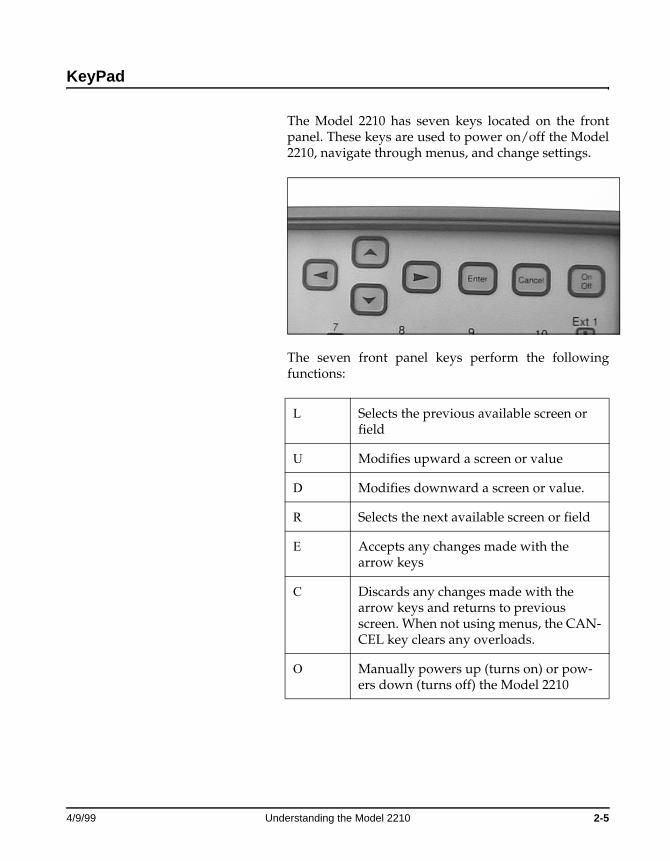
KeyPad
The Model 2210 has seven keys located on the front panel. These keys are used to power on/off the Model 2210, navigate through menus, and change settings.
The seven front panel keys perform the following functions:
L Selects the previous available screen or field
U Modifies upward a screen or value
D Modifies downward a screen or value.
R Selects the next available screen or field
E Accepts any changes made with the arrow keys
C Discards any changes made with the arrow keys and returns to previous screen. When not using menus, the CAN-CEL key clears any overloads.
O Manually powers up (turns on) or pow-ers down (turns off) the Model 2210
4/9/99 Understanding the Model 2210 2-5
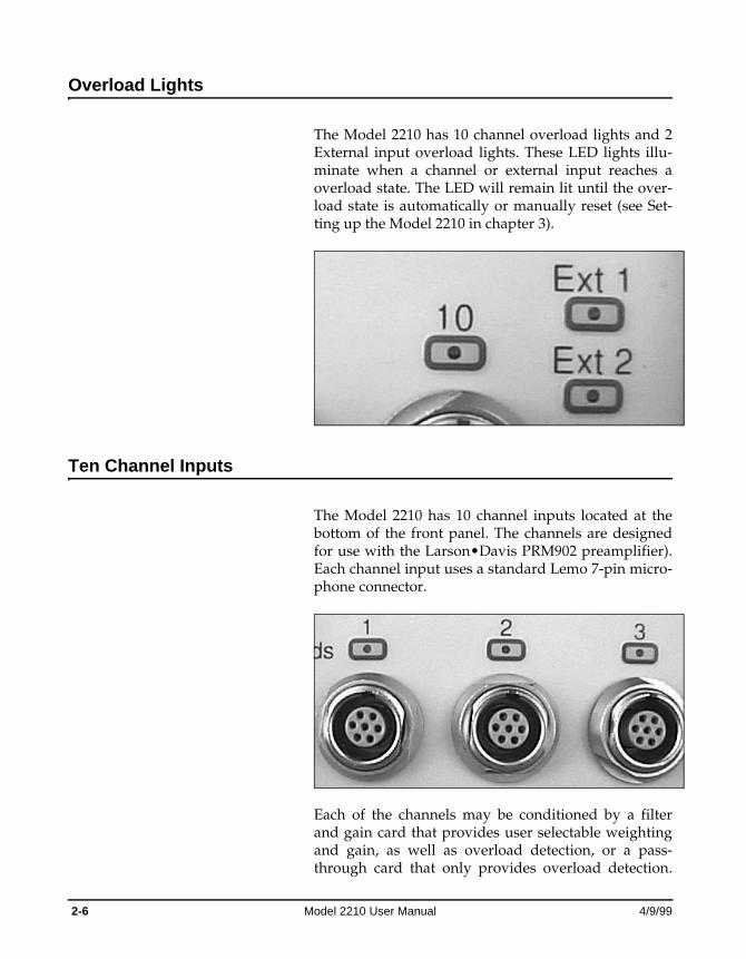
Overload Lights
The Model 2210 has 10 channel overload lights and 2 External input overload lights. These LED lights illu-minate when a channel or external input reaches a overload state. The LED will remain lit until the over-load state is automatically or manually reset (see Set-ting up the Model 2210 in chapter 3).
Ten Channel Inputs
The Model 2210 has 10 channel inputs located at the bottom of the front panel. The channels are designed for use with the Larson•Davis PRM902 preamplifier). Each channel input uses a standard Lemo 7-pin micro-phone connector.
Each of the channels may be conditioned by a filter and gain card that provides user selectable weighting and gain, as well as overload detection, or a pass-through card that only provides overload detection.
2-6 Model 2210 User Manual 4/9/99

The firmware also recognizes if a channel has no card installed at all (see Setting up the Model 2210 in Chap-ter 3).
Understanding the Model 2210 Back Panel
The back panel of the Model 2210 contains of the fol-lowing, each are then explained in greater detail:
• Internal NiCd battery pack compartment
• Insert Voltage Calibration
• Two external inputs
• Two multiplexer (MUX) outputs
• A 25-pin Signal output interface
• A RS-232 interface
• Fuses (one 2A and one 3A)
• An external power input
7 - Power Supply Ground
4 - Signal
1 - Insert voltage calibration
2 - Ground
3 - Microphone Bias voltage
6 - preamp power (+28 V)
4/9/99 Understanding the Model 2210 2-7
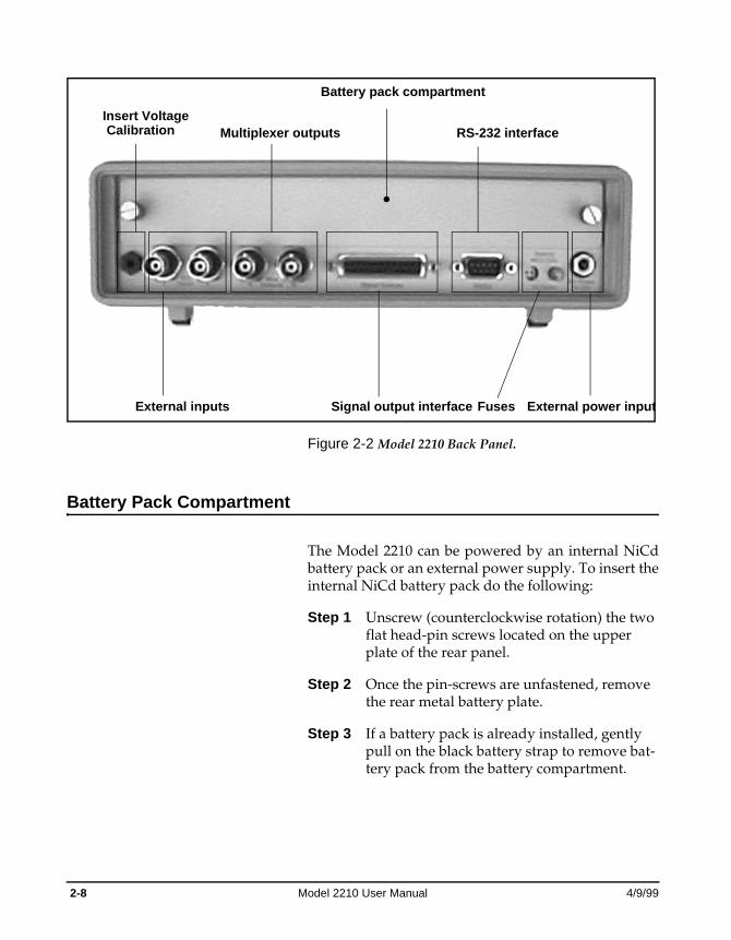
Figure 2-2 Model 2210 Back Panel.
Battery Pack Compartment
The Model 2210 can be powered by an internal NiCd battery pack or an external power supply. To insert the internal NiCd battery pack do the following:
Step 1 Unscrew (counterclockwise rotation) the two flat head-pin screws located on the upper plate of the rear panel.
Step 2 Once the pin-screws are unfastened, remove the rear metal battery plate.
Step 3 If a battery pack is already installed, gently pull on the black battery strap to remove bat-tery pack from the battery compartment.
Battery pack compartment
External inputs
Multiplexer outputs
Signal output interface
RS-232 interface
Fuses External power input
Insert VoltageCalibration
2-8 Model 2210 User Manual 4/9/99
Replace only with a NiCd battery pack as the charger is set up for NiCd only. Caution: Pay particular attention to the positive and negative poles on the battery. If the battery is inserted incorrectly, the battery fuse may blow.
Step 4 Place new NiCd battery pack in the battery compartment the metal leads towards the springs.
Step 5 Place rear metal battery plate over the battery compartment
Step 6 Screw in and fasten the pin-screws in the holes of the battery plate to secure the battery compartment.
The internal battery life is approximately 6 hours.
Alternatively, you may use an external power source via the 11-16V external power connector. To do this, insert the PSA-004 power supply into the external power connector.
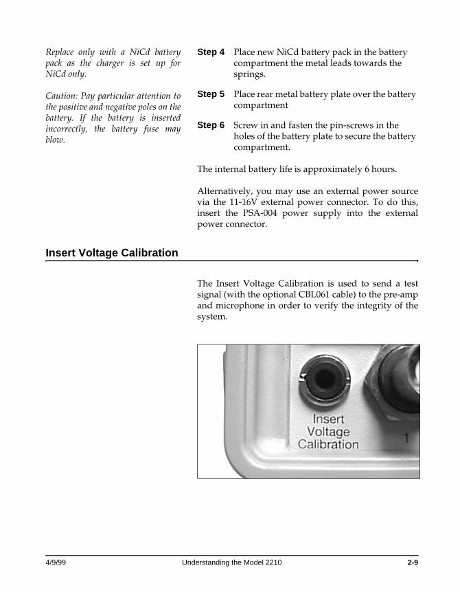
Insert Voltage Calibration
The Insert Voltage Calibration is used to send a test signal (with the optional CBL061 cable) to the pre-amp and microphone in order to verify the integrity of the system.
4/9/99 Understanding the Model 2210 2-9
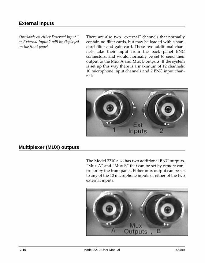
External Inputs
Overloads on either External Input 1 or External Input 2 will be displayed on the front panel.
There are also two “external” channels that normally contain no filter cards, but may be loaded with a stan-dard filter and gain card. These two additional chan-nels take their input from the back panel BNC connectors, and would normally be set to send their output to the Mux A and Mux B outputs. If the system is set up this way there is a maximum of 12 channels: 10 microphone input channels and 2 BNC input chan-nels.
Multiplexer (MUX) outputs
The Model 2210 also has two additional BNC outputs, “Mux A” and “Mux B” that can be set by remote con-trol or by the front panel. Either mux output can be set to any of the 10 microphone inputs or either of the two external inputs.
2-10 Model 2210 User Manual 4/9/99
Using the external inputs and multiple 2210s allows expansion to a large number of channels.
Note: Automated scanning of the channels is not offered in the firmware. If you have an application that needs automated scanning, it can be accomplished by using the RS232 commands and a computer. (See Appendix B)
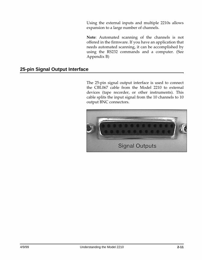
25-pin Signal Output Interface
The 25-pin signal output interface is used to connect the CBL067 cable from the Model 2210 to external devices (tape recorder, or other instruments). This cable splits the input signal from the 10 channels to 10 output BNC connectors.
4/9/99 Understanding the Model 2210 2-11
RS-232 interface
The RS-232 connector is for use with external remote control of the Model 2210. Use the CBL045 cable to connect multiple 2210’s on a single RS-232 computer port. (See Appendix B for addressing multiple 2210s.)
Fuses
See Chapter 1, “Accessories and Optional Equipment”, page 1-7 for replacement part numbers.
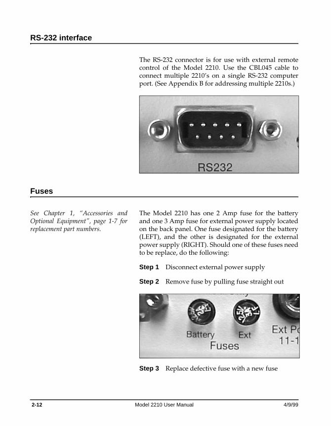
The Model 2210 has one 2 Amp fuse for the battery and one 3 Amp fuse for external power supply located on the back panel. One fuse designated for the battery (LEFT), and the other is designated for the external power supply (RIGHT). Should one of these fuses need to be replace, do the following:
Step 1 Disconnect external power supply
Step 2 Remove fuse by pulling fuse straight out
Step 3 Replace defective fuse with a new fuse
2-12 Model 2210 User Manual 4/9/99
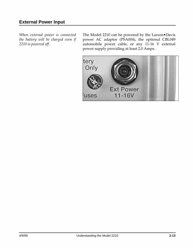
External Power Input
When external power is connected the battery will be charged even if 2210 is powered off.
The Model 2210 can be powered by the Larson•Davis power AC adaptor (PSA004), the optional CBL049 automobile power cable, or any 11-16 V external power supply providing at least 2.0 Amps.
4/9/99 Understanding the Model 2210 2-13
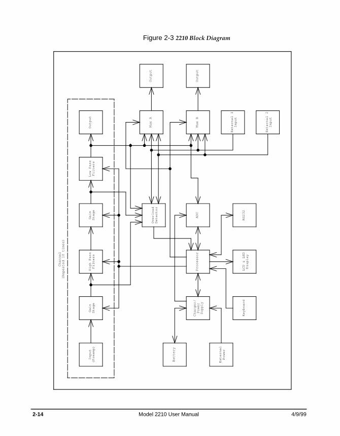
Figure 2-3 2210 Block Diagram
Overload
Detector
High Pass
Filters
Gain
Stage
Gain
Stage
Channel
(Repeated 10 times)
Input
(Preamp)
Processor
Output
Output
Output
Mux A
Mux B
External 1
Input
External 2
Input
Battery
External
Power
Charger/
Power
Supply
Keyboard
RS232
ADC
LCD & LED
Display
Low Pass
Filters
2-14 Model 2210 User Manual 4/9/99
C H A P T E R
3 Setting up the Model 2210
Once your Model 2210 is unpacked and connected to a battery (or external power supply), you can turn it on and perform sound and vibration recording and mea-surements. In this chapter, the following is discussed:
• Turning on the Model 2210
• Using menu items
• Turning off the Model 2210
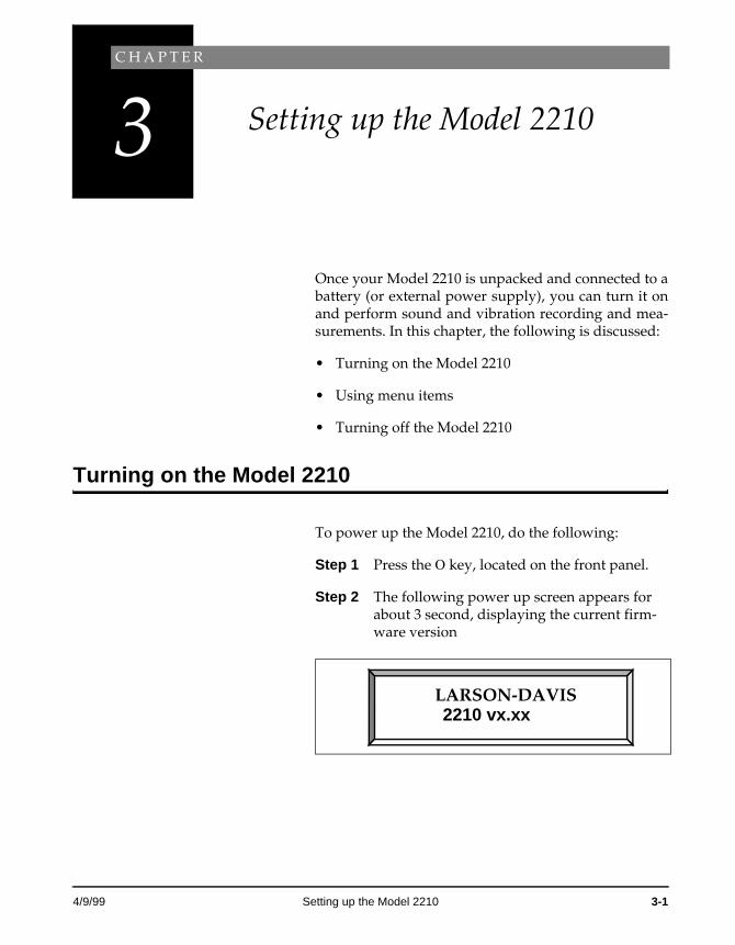
Turning on the Model 2210
To power up the Model 2210, do the following:
Step 1 Press the O key, located on the front panel.
Step 2 The following power up screen appears for about 3 second, displaying the current firm-ware version
LARSON-DAVIS2210 vx.xx
4/9/99 Setting up the Model 2210 3-1
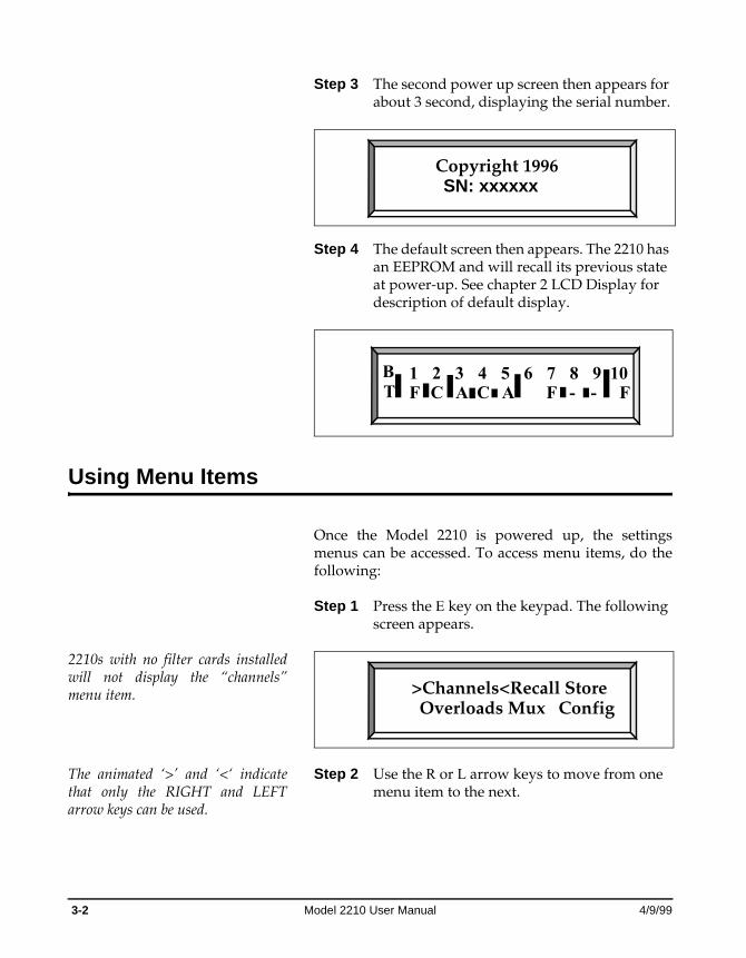
Step 3 The second power up screen then appears for about 3 second, displaying the serial number.
Step 4 The default screen then appears. The 2210 has an EEPROM and will recall its previous state at power-up. See chapter 2 LCD Display for description of default display.
Using Menu Items
Once the Model 2210 is powered up, the settings menus can be accessed. To access menu items, do the following:
2210s with no filter cards installed will not display the “channels” menu item.
Step 1 Press the E key on the keypad. The following screen appears.
The animated ‘>’ and ‘<‘ indicate that only the RIGHT and LEFT arrow keys can be used.
Step 2 Use the R or L arrow keys to move from one menu item to the next.
Copyright 1996SN: xxxxxx
1 2 3 4 5 6 7 8 9 10T F C -AB
FFC -A
>Channels<Recall StoreOverloads Mux Config
3-2 Model 2210 User Manual 4/9/99
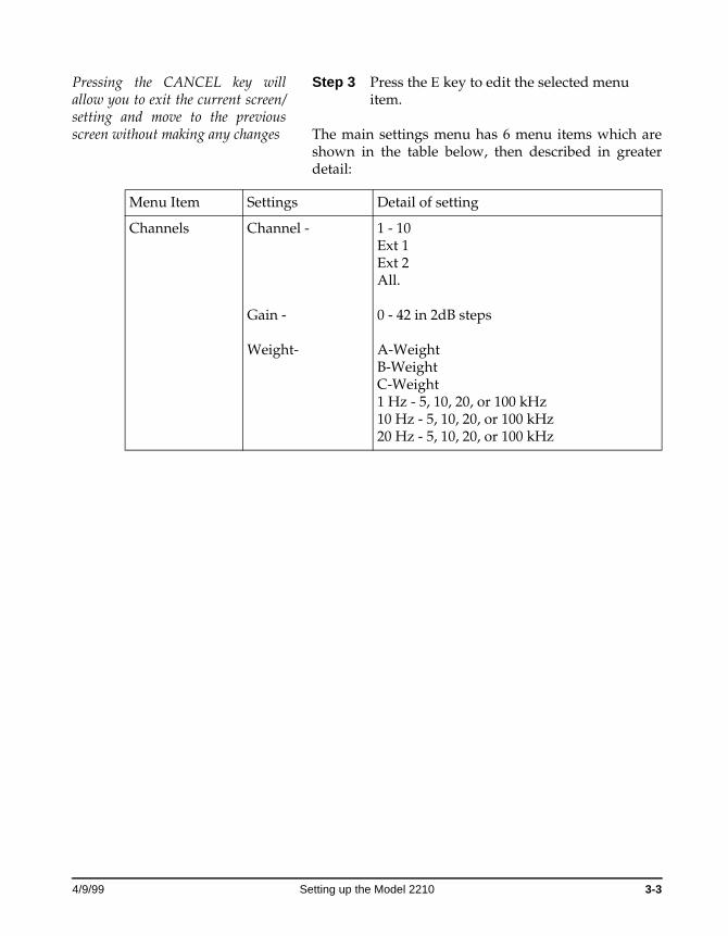
Pressing the CANCEL key will allow you to exit the current screen/setting and move to the previous screen without making any changes
Step 3 Press the E key to edit the selected menu item.
The main settings menu has 6 menu items which are shown in the table below, then described in greater detail:
Menu Item Settings Detail of setting
Channels Channel -
Gain -
Weight-
1 - 10 Ext 1Ext 2 All.
0 - 42 in 2dB steps
A-WeightB-WeightC-Weight1 Hz - 5, 10, 20, or 100 kHz10 Hz - 5, 10, 20, or 100 kHz20 Hz - 5, 10, 20, or 100 kHz
4/9/99 Setting up the Model 2210 3-3
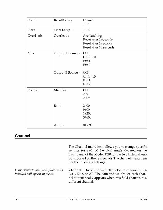
Channel
The Channel menu item allows you to change specific settings for each of the 10 channels (located on the front panel of the Model 2210, or the two External out-puts located on the rear panel). The channel menu item has the following settings:
Only channels that have filter cards installed will appear in the list
Channel - This is the currently selected channel: 1 -10, Ext1, Ext2, or All. The gain and weight for each chan-nel automatically appears when this field changes to a different channel.
Recall Recall Setup - Default1 - 8
Store Store Setup - 1 - 8
Overloads Overloads Are LatchingReset after 2 secondsReset after 5 secondsReset after 10 seconds
Mux Output A Source -
Output B Source -
OffCh 1 - 10Ext 1Ext 2
OffCh 1 - 10Ext 1Ext 2
Config Mic Bias -
Baud -
Addr -
Off28v200v
240096001920057600
01 - 99
3-4 Model 2210 User Manual 4/9/99
The first slot that has a filter card installed is used as the ‘master’ when modifying values and the channel is set to ‘All’. For instance, if a 2210 had no filter cards installed in slots 1 and 2, then channel 3’s value would be copied to all the other channels when u or d is pressed on a ‘--’ field.
If “All” is selected and some items are not the same for all the channels, then those items will display “--”. For instance, if the gain for channel 1 is 10 and the gains for the other channels are 30, then when “All” is selected for the channel, “--” will show as the gain.
If you use the u and d keys to modify a field that shows ‘--’, then the first u or d key will set all the other channel’s values to channel 1’s value and display that value, subsequent u or d keys will modify all the channels values.
Gain - This is the current gain setting for the selected channel. Gain can be set between 0 - 42 in 2dB incre-ments.
Weight - This is the current weight setting for the selected channel. The Weight setting has the following possibilities: A-Weight B-Weight C-Weight 1 Hz - 5, 10, 20, 100 kHz 10 Hz - 5, 10, 20, 100 kHz 20 Hz - 5, 10, 20, 100 kHz
Recall
The Recall menu item allows you to restore previous complete setups, or a original factor default setup. This menu item works with the Store menu item. The recall menu item has the following settings:
Default - Default factory setup which is 0db gain 20Hz to 20kHz flat, 5 second non-latching overloads, Mux A's output off, Mux B's output off, and the Mic bias voltage off.
1- 8 - The Recall menu item allows you to recall one of eight possible setups.
4/9/99 Setting up the Model 2210 3-5
If a setup is recalled that has never been stored, it is identical to the fac-tory default setup. The “Default” setup will always recall the factory default setup.
To recall a setup:
Step 1 Use the R or L arrow keys to select one of eight previously stored setups.
Step 2 Press the E key to recall that setup from EEPROM and make the current setup.
Store
The Store menu item allows you to store the current setup of the Model 2210, which can later be recalled. This menu item works with the Recall menu item. The store menu item has the following settings:
1- 8 - The Store menu item allows you to store the cur-rent setup of the Model 2210 into one of eight EEPROM storage locations. Stores gain, filter settings, overload settings, Mux A and B settings, and Mic Bias voltage.
To store the current Model 2210 setup:
Step 1 Use the R or L arrow keys to select one of eight EEPROM storage location.
Step 2 Press the E key to store the current setup to EEPROM.
Overloads
The Overload menu item allows you to tell the Model 2210 how to handle overloads. This menu item has the following settings:
The C key may be used to clean the automatically resetting overloads early.
Are Latching - When overload occurs, overload will not automatically be reset, but must be manually reset by pressing the C key.
Reset after 2 seconds - The overload will be reset 2 sec-onds after an overload occurs.
3-6 Model 2210 User Manual 4/9/99
Reset after 5 seconds - The overload will be reset 5 sec-onds after an overload occurs.
Reset after 10 seconds - The overload will be reset 10 seconds after an overload occurs.
The Overload LED will flash to indicate a current over-load. After the overload condition is cleared, the LED will cease flashing and turn solid until it is reset. It is reset by either pressing the C key or if one of the above options (2, 5, or 10 seconds) time periods has elapsed without a further overload.
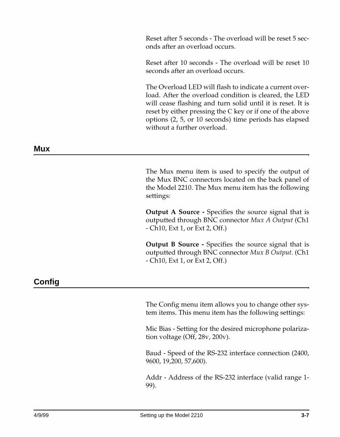
Mux
The Mux menu item is used to specify the output of the Mux BNC connectors located on the back panel of the Model 2210. The Mux menu item has the following settings:
Output A Source - Specifies the source signal that is outputted through BNC connector Mux A Output (Ch1 - Ch10, Ext 1, or Ext 2, Off.)
Output B Source - Specifies the source signal that is outputted through BNC connector Mux B Output. (Ch1 - Ch10, Ext 1, or Ext 2, Off.)
Config
The Config menu item allows you to change other sys-tem items. This menu item has the following settings:
Mic Bias - Setting for the desired microphone polariza-tion voltage (Off, 28v, 200v).
Baud - Speed of the RS-232 interface connection (2400, 9600, 19,200, 57,600).
Addr - Address of the RS-232 interface (valid range 1-99).
4/9/99 Setting up the Model 2210 3-7

Turning off the Model 2210
The Model 2210 can be powered down at any time by pressing the O key on the keypad. Note that powering down the 2210, while you are still in a menu, will cause any changes you made to be lost. To accept any changes,press the E key prior to powering down.
The 2210 will shut its self off when it detects a low bat-tery.
3-8 Model 2210 User Manual 4/9/99
A P P E N D I X
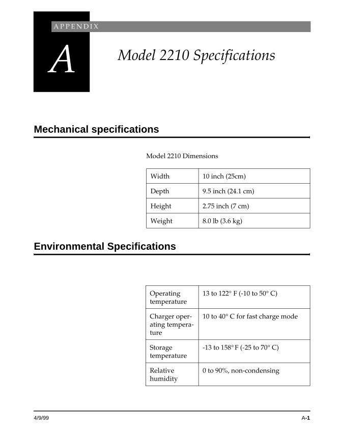
A Model 2210 Specifications
Mechanical specifications
Model 2210 Dimensions
Environmental Specifications
Width 10 inch (25cm)
Depth 9.5 inch (24.1 cm)
Height 2.75 inch (7 cm)
Weight 8.0 lb (3.6 kg)
Operating temperature
13 to 122° F (-10 to 50° C)
Charger oper-ating tempera-ture
10 to 40° C for fast charge mode
Storage temperature
-13 to 158° F (-25 to 70° C)
Relative humidity
0 to 90%, non-condensing
4/9/99 A-1
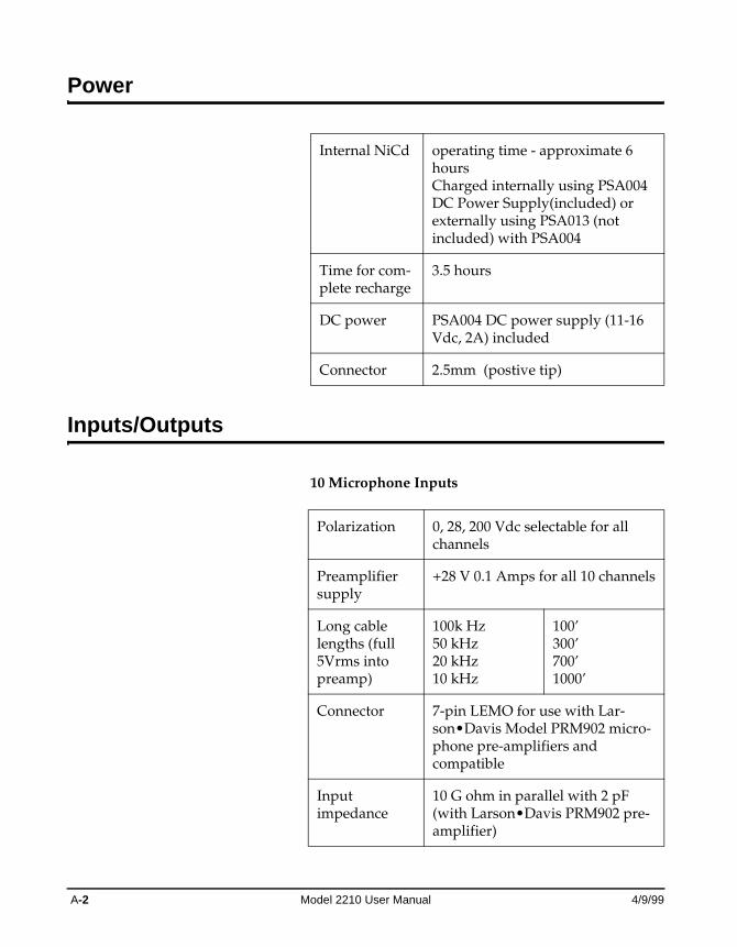
Power
Inputs/Outputs
10 Microphone Inputs
Internal NiCd operating time - approximate 6 hoursCharged internally using PSA004 DC Power Supply(included) or externally using PSA013 (not included) with PSA004
Time for com-plete recharge
3.5 hours
DC power PSA004 DC power supply (11-16 Vdc, 2A) included
Connector 2.5mm (postive tip)
Polarization 0, 28, 200 Vdc selectable for all channels
Preamplifier supply
+28 V 0.1 Amps for all 10 channels
Long cable lengths (full 5Vrms into preamp)
100k Hz 50 kHz 20 kHz 10 kHz
100’ 300’700’1000’
Connector 7-pin LEMO for use with Lar-son•Davis Model PRM902 micro-phone pre-amplifiers and compatible
Input impedance
10 G ohm in parallel with 2 pF (with Larson•Davis PRM902 pre-amplifier)
A-2 Model 2210 User Manual 4/9/99
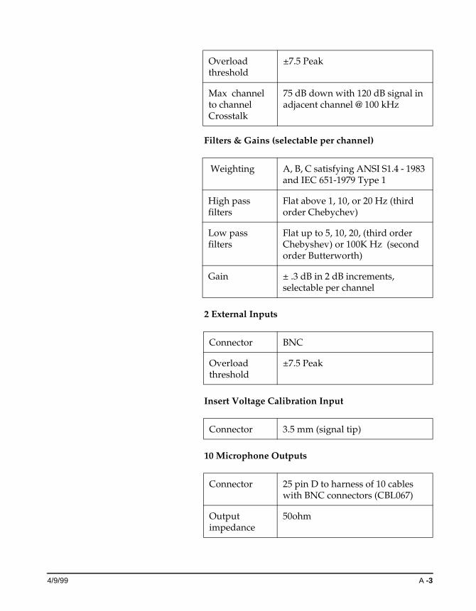
Filters & Gains (selectable per channel)
2 External Inputs
Insert Voltage Calibration Input
10 Microphone Outputs
Overload threshold
±7.5 Peak
Max channel to channel Crosstalk
75 dB down with 120 dB signal in adjacent channel @ 100 kHz
Weighting A, B, C satisfying ANSI S1.4 - 1983 and IEC 651-1979 Type 1
High pass filters
Flat above 1, 10, or 20 Hz (third order Chebychev)
Low pass filters
Flat up to 5, 10, 20, (third order Chebyshev) or 100K Hz (second order Butterworth)
Gain ± .3 dB in 2 dB increments,selectable per channel
Connector BNC
Overload threshold
±7.5 Peak
Connector 3.5 mm (signal tip)
Connector 25 pin D to harness of 10 cables with BNC connectors (CBL067)
Output impedance
50ohm
4/9/99 A -3
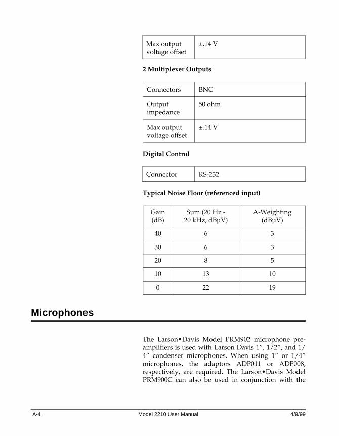
2 Multiplexer Outputs
Digital Control
Typical Noise Floor (referenced input)
Microphones
The Larson•Davis Model PRM902 microphone pre-amplifiers is used with Larson Davis 1”, 1/2”, and 1/4” condenser microphones. When using 1” or 1/4” microphones, the adaptors ADP011 or ADP008, respectively, are required. The Larson•Davis Model PRM900C can also be used in conjunction with the
Max output voltage offset
±.14 V
Connectors BNC
Output impedance
50 ohm
Max output voltage offset
±.14 V
Connector RS-232
Gain(dB)
Sum (20 Hz - 20 kHz, dBµV)
A-Weighting(dBµV)
40 6 3
30 6 3
20 8 5
10 13 10
0 22 19
A-4 Model 2210 User Manual 4/9/99
CBL079 7-pin-LEMO-to-5-pin Switchcraft cable adap-tor.
Accelerometers
When using ICP accelerometers, a Larson•Davis Model PRA950 ICP accelerometer pre-amplifier at the outboard end of a microphone extension cable (CBL079) will provide the DC current (2-4 mA) required to power the accelerometer.
When using charge-coupled accelerometers, the Lar-son•Davis Model PRM902 microphone pre-amplifier at the outboard end of the microphone extension cable will provide sufficient input impedance. Use the adap-tor ADP005 in place of the microphone for use with BNC connectors and the ADP007 for use with micro-dot connectors.
4/9/99 A -5

A-6 Model 2210 User Manual 4/9/99
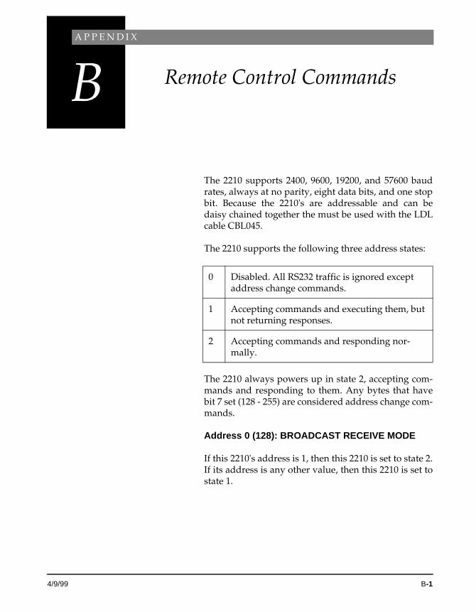
A P P E N D I X
B Remote Control Commands
The 2210 supports 2400, 9600, 19200, and 57600 baud rates, always at no parity, eight data bits, and one stop bit. Because the 2210's are addressable and can be daisy chained together the must be used with the LDL cable CBL045.
The 2210 supports the following three address states:
The 2210 always powers up in state 2, accepting com-mands and responding to them. Any bytes that have bit 7 set (128 - 255) are considered address change com-mands.
Address 0 (128): BROADCAST RECEIVE MODE
If this 2210's address is 1, then this 2210 is set to state 2. If its address is any other value, then this 2210 is set to state 1.
0 Disabled. All RS232 traffic is ignored except address change commands.
1 Accepting commands and executing them, but not returning responses.
2 Accepting commands and responding nor-mally.
4/9/99 B-1
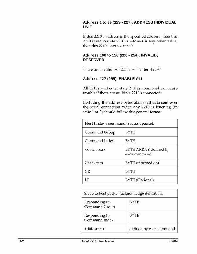
Address 1 to 99 (129 - 227): ADDRESS INDIVIDUAL UNIT
If this 2210's address is the specified address, then this 2210 is set to state 2. If its address is any other value, then this 2210 is set to state 0.
Address 100 to 126 (228 - 254): INVALID, RESERVED
These are invalid. All 2210's will enter state 0.
Address 127 (255): ENABLE ALL
All 2210's will enter state 2. This command can cause trouble if there are multiple 2210's connected.
Excluding the address bytes above, all data sent over the serial connection when any 2210 is listening (in state 1 or 2) should follow this general format.
Host to slave command/request packet.
Command Group BYTE
Command Index BYTE
<data area> BYTE ARRAY defined by each command
Checksum BYTE (if turned on)
CR BYTE
LF BYTE (Optional)
Slave to host packet/acknowledge definition.
Responding to Command Group
BYTE
Responding toCommand Index
BYTE
<data area> defined by each command
B-2 Model 2210 User Manual 4/9/99
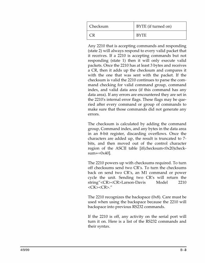
Any 2210 that is accepting commands and responding (state 2) will always respond to every valid packet that it receives. If a 2210 is accepting commands but not responding (state 1) then it will only execute valid packets. Once the 2210 has at least 3 bytes and receives a CR, then it adds up the checksum and compares it with the one that was sent with the packet. If the checksum is valid the 2210 continues to parse the com-mand checking for valid command group, command index, and valid data area (if this command has any data area). If any errors are encountered they are set in the 2210's internal error flags. These flags may be que-ried after every command or group of commands to make sure that those commands did not generate any errors.
The checksum is calculated by adding the command group, Command index, and any bytes in the data area in an 8-bit register, discarding overflows. Once the characters are added up, the result is truncated to 7-bits, and then moved out of the control character region of the ASCII table [if(checksum<0x20)check-sum+=0x40].
The 2210 powers up with checksums required. To turn off checksums send two CR’s. To turn the checksums back on send two CR’s, an M1 command or power cycle the unit. Sending two CR’s will return the string”<CR><CR>Larson-Davis Model 2210 <CK><CR>.”
The 2210 recognizes the backspace (0x8). Care must be used when using the backspace because the 2210 will backspace into previous RS232 commands.
If the 2210 is off, any activity on the serial port will turn it on. Here is a list of the RS232 commands and their syntax.
Checksum BYTE (if turned on)
CR BYTE
4/9/99 B -3
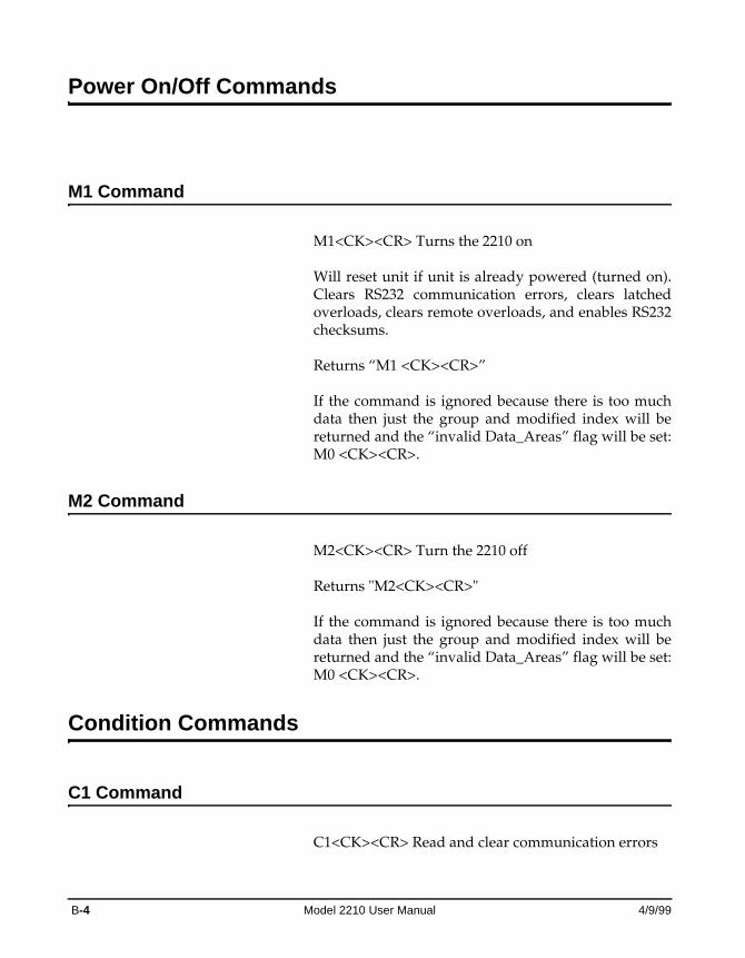
Power On/Off Commands
M1 Command
M1<CK><CR> Turns the 2210 on Will reset unit if unit is already powered (turned on). Clears RS232 communication errors, clears latched overloads, clears remote overloads, and enables RS232 checksums.
Returns “M1 <CK><CR>”
If the command is ignored because there is too much data then just the group and modified index will be returned and the “invalid Data_Areas” flag will be set: M0 <CK><CR>.
M2 Command
M2<CK><CR> Turn the 2210 off
Returns "M2<CK><CR>"
If the command is ignored because there is too much data then just the group and modified index will be returned and the “invalid Data_Areas” flag will be set: M0 <CK><CR>.
Condition Commands
C1 Command
C1<CK><CR> Read and clear communication errors
B-4 Model 2210 User Manual 4/9/99
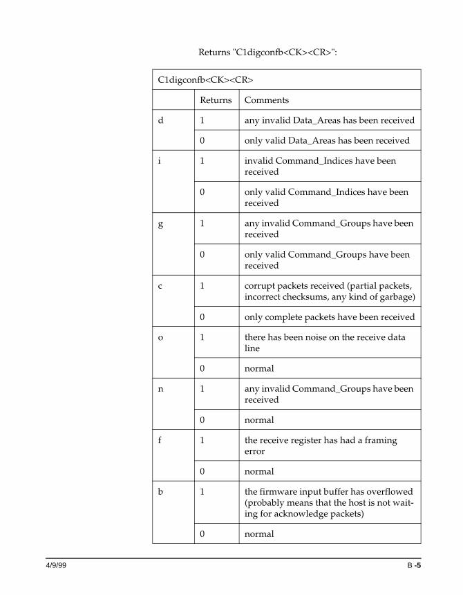
Returns "C1digconfb<CK><CR>":
C1digconfb<CK><CR>
Returns Comments
d 1 any invalid Data_Areas has been received
0 only valid Data_Areas has been received
i 1 invalid Command_Indices have been received
0 only valid Command_Indices have been received
g 1 any invalid Command_Groups have been received
0 only valid Command_Groups have been received
c 1 corrupt packets received (partial packets, incorrect checksums, any kind of garbage)
0 only complete packets have been received
o 1 there has been noise on the receive data line
0 normal
n 1 any invalid Command_Groups have been received
0 normal
f 1 the receive register has had a framing error
0 normal
b 1 the firmware input buffer has overflowed (probably means that the host is not wait-ing for acknowledge packets)
0 normal
4/9/99 B -5
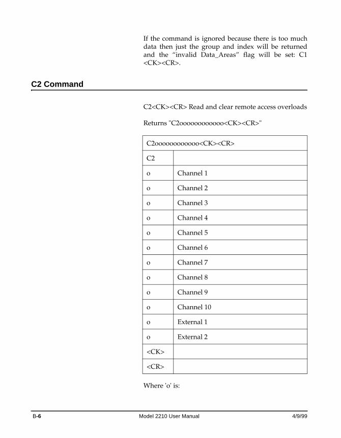
If the command is ignored because there is too much data then just the group and index will be returned and the “invalid Data_Areas” flag will be set: C1 <CK><CR>.
C2 Command
C2<CK><CR> Read and clear remote access overloads
Returns "C2oooooooooooo<CK><CR>"
Where 'o' is:
C2oooooooooooo<CK><CR>
C2
o Channel 1
o Channel 2
o Channel 3
o Channel 4
o Channel 5
o Channel 6
o Channel 7
o Channel 8
o Channel 9
o Channel 10
o External 1
o External 2
<CK>
<CR>
B-6 Model 2210 User Manual 4/9/99
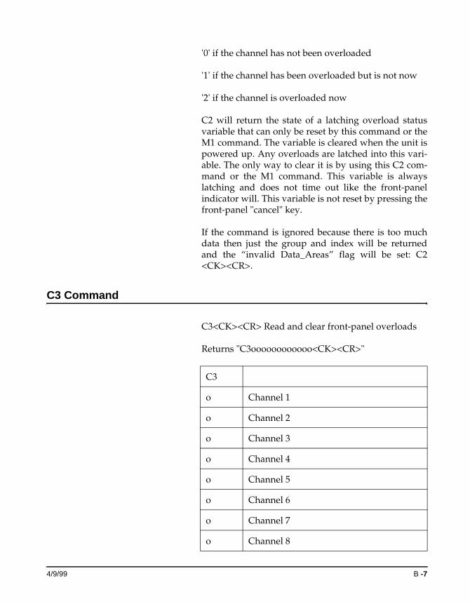
'0' if the channel has not been overloaded
'1' if the channel has been overloaded but is not now
'2' if the channel is overloaded now
C2 will return the state of a latching overload status variable that can only be reset by this command or the M1 command. The variable is cleared when the unit is powered up. Any overloads are latched into this vari-able. The only way to clear it is by using this C2 com-mand or the M1 command. This variable is always latching and does not time out like the front-panel indicator will. This variable is not reset by pressing the front-panel "cancel" key.
If the command is ignored because there is too much data then just the group and index will be returned and the “invalid Data_Areas” flag will be set: C2 <CK><CR>.
C3 Command
C3<CK><CR> Read and clear front-panel overloads
Returns "C3oooooooooooo<CK><CR>"
C3
o Channel 1
o Channel 2
o Channel 3
o Channel 4
o Channel 5
o Channel 6
o Channel 7
o Channel 8
4/9/99 B -7
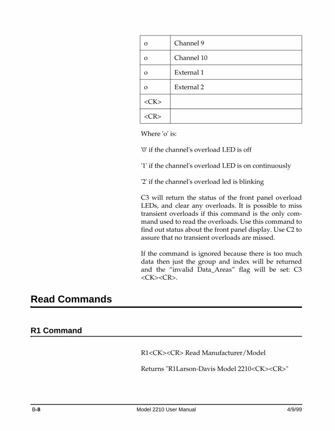
Where 'o' is:
'0' if the channel's overload LED is off
'1' if the channel's overload LED is on continuously
'2' if the channel's overload led is blinking
C3 will return the status of the front panel overload LEDs, and clear any overloads. It is possible to miss transient overloads if this command is the only com-mand used to read the overloads. Use this command to find out status about the front panel display. Use C2 to assure that no transient overloads are missed.
If the command is ignored because there is too much data then just the group and index will be returned and the “invalid Data_Areas” flag will be set: C3 <CK><CR>.
Read Commands
R1 Command
R1<CK><CR> Read Manufacturer/Model
Returns "R1Larson-Davis Model 2210<CK><CR>"
o Channel 9
o Channel 10
o External 1
o External 2
<CK>
<CR>
B-8 Model 2210 User Manual 4/9/99
If the command is ignored because there is too much data then just the group and index will be returned and the “invalid Data_Areas” flag will be set: R1 <CK><CR>.
R2 Command
R2<CK><CR> Read firmware version and Serial Number
Returns "R2v.vv nnnnnn<CK><CR>"
If the command is ignored because there is too much data then just the group and index will be returned and the “invalid Data_Areas” flag will be set: R2 <CK><CR>.
R3 Command
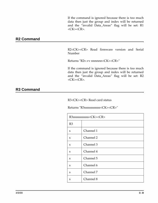
R3<CK><CR> Read card status
Returns "R3ssssssssssss<CK><CR>"
R3ssssssssssss<CK><CR>
R3
s Channel 1
s Channel 2
s Channel 3
s Channel 4
s Channel 5
s Channel 6
s Channel 7
s Channel 8
4/9/99 B -9
Where each s represents the status of the correspond-ing slot:
F = full filter card
B = buffer only card
- = empty slot
If the command is ignored because there is too much data then just the group and index will be returned and the “invalid Data_Areas” flag will be set: R3 <CK><CR>.
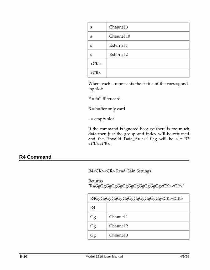
R4 Command
R4<CK><CR> Read Gain Settings
Returns "R4GgGgGgGgGgGgGgGgGgGgGgGg<CK><CR>"
s Channel 9
s Channel 10
s External 1
s External 2
<CK>
<CR>
R4GgGgGgGgGgGgGgGgGgGgGgGg<CK><CR>
R4
Gg Channel 1
Gg Channel 2
Gg Channel 3
B-10 Model 2210 User Manual 4/9/99
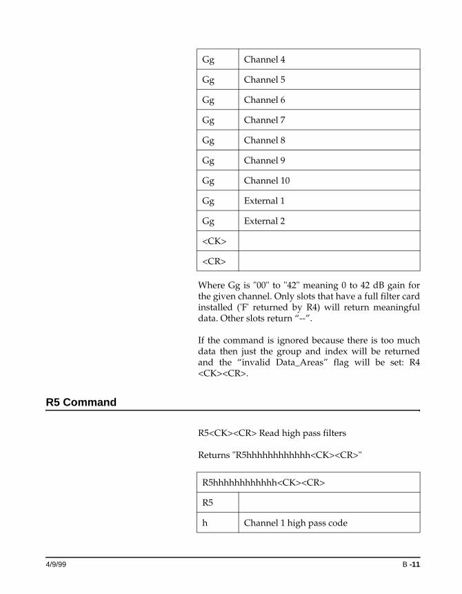
Where Gg is "00" to "42" meaning 0 to 42 dB gain for the given channel. Only slots that have a full filter card installed ('F' returned by R4) will return meaningful data. Other slots return “--”.
If the command is ignored because there is too much data then just the group and index will be returned and the “invalid Data_Areas” flag will be set: R4 <CK><CR>.
R5 Command
R5<CK><CR> Read high pass filters
Returns "R5hhhhhhhhhhhh<CK><CR>"
Gg Channel 4
Gg Channel 5
Gg Channel 6
Gg Channel 7
Gg Channel 8
Gg Channel 9
Gg Channel 10
Gg External 1
Gg External 2
<CK>
<CR>
R5hhhhhhhhhhhh<CK><CR>
R5
h Channel 1 high pass code
4/9/99 B -11
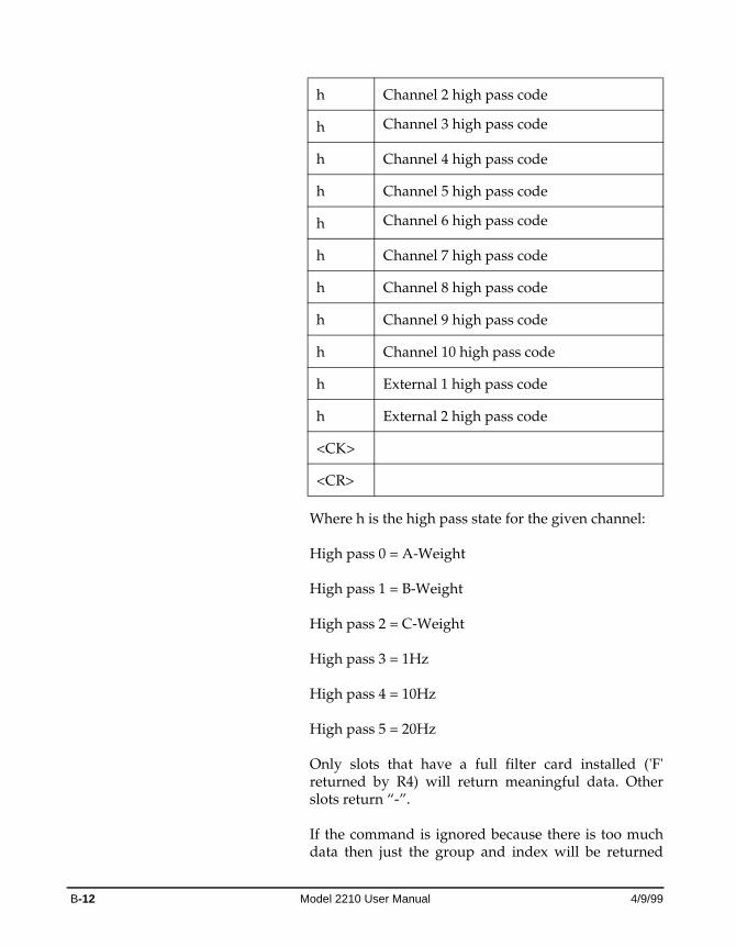
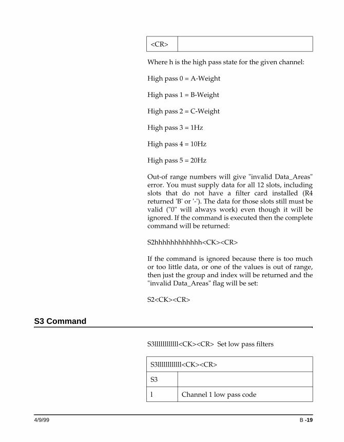
Where h is the high pass state for the given channel:
High pass 0 = A-Weight
High pass 1 = B-Weight
High pass 2 = C-Weight
High pass 3 = 1Hz
High pass 4 = 10Hz
High pass 5 = 20Hz
Only slots that have a full filter card installed ('F' returned by R4) will return meaningful data. Other slots return “-”.
If the command is ignored because there is too much data then just the group and index will be returned
h Channel 2 high pass code
h Channel 3 high pass code
h Channel 4 high pass code
h Channel 5 high pass code
h Channel 6 high pass code
h Channel 7 high pass code
h Channel 8 high pass code
h Channel 9 high pass code
h Channel 10 high pass code
h External 1 high pass code
h External 2 high pass code
<CK>
<CR>
B-12 Model 2210 User Manual 4/9/99
and the “invalid Data_Areas” flag will be set: R5 <CK><CR>.
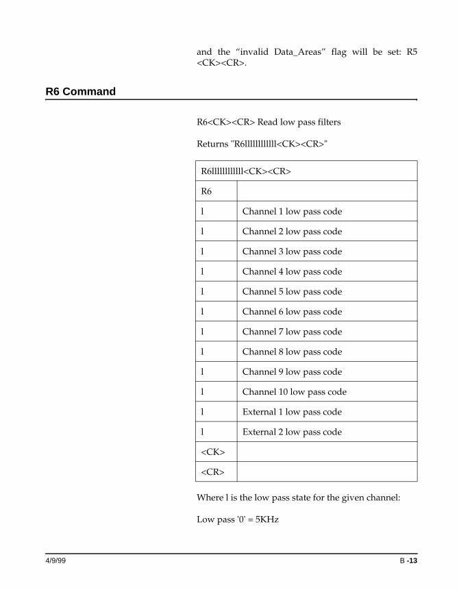
R6 Command
R6<CK><CR> Read low pass filters
Returns "R6llllllllllll<CK><CR>"
Where l is the low pass state for the given channel:
Low pass '0' = 5KHz
R6llllllllllll<CK><CR>
R6
l Channel 1 low pass code
l Channel 2 low pass code
l Channel 3 low pass code
l Channel 4 low pass code
l Channel 5 low pass code
l Channel 6 low pass code
l Channel 7 low pass code
l Channel 8 low pass code
l Channel 9 low pass code
l Channel 10 low pass code
l External 1 low pass code
l External 2 low pass code
<CK>
<CR>
4/9/99 B -13
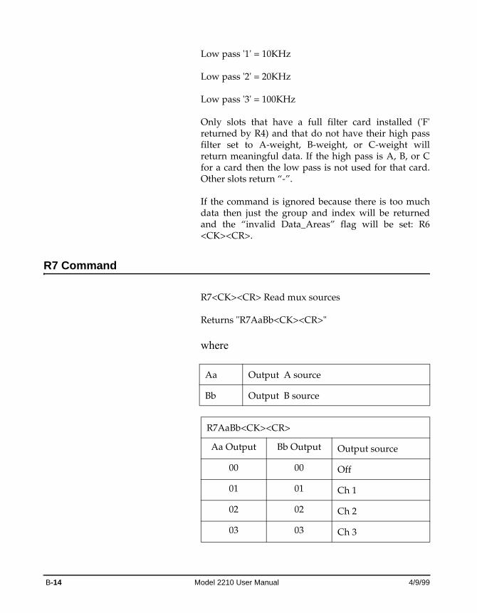
Low pass '1' = 10KHz
Low pass '2' = 20KHz
Low pass '3' = 100KHz
Only slots that have a full filter card installed ('F' returned by R4) and that do not have their high pass filter set to A-weight, B-weight, or C-weight will return meaningful data. If the high pass is A, B, or C for a card then the low pass is not used for that card. Other slots return “-”.
If the command is ignored because there is too much data then just the group and index will be returned and the “invalid Data_Areas” flag will be set: R6 <CK><CR>.
R7 Command
R7<CK><CR> Read mux sources
Returns "R7AaBb<CK><CR>"
where
Aa Output A source
Bb Output B source
R7AaBb<CK><CR>
Aa Output Bb Output Output source
00 00 Off
01 01 Ch 1
02 02 Ch 2
03 03 Ch 3
B-14 Model 2210 User Manual 4/9/99
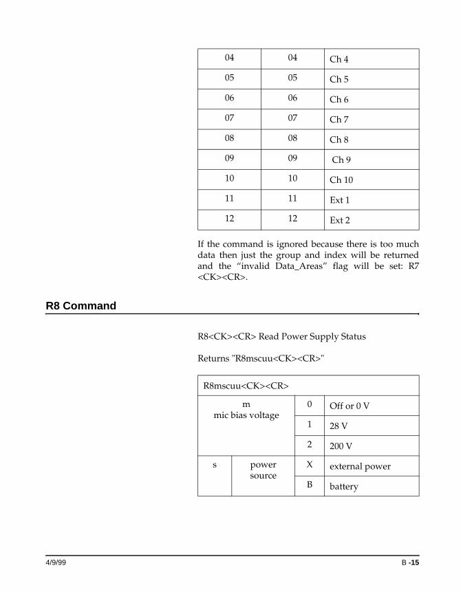
If the command is ignored because there is too much data then just the group and index will be returned and the “invalid Data_Areas” flag will be set: R7 <CK><CR>.
R8 Command
R8<CK><CR> Read Power Supply Status
Returns "R8mscuu<CK><CR>"
04 04 Ch 4
05 05 Ch 5
06 06 Ch 6
07 07 Ch 7
08 08 Ch 8
09 09 Ch 9
10 10 Ch 10
11 11 Ext 1
12 12 Ext 2
R8mscuu<CK><CR>
mmic bias voltage
0 Off or 0 V
1 28 V
2 200 V
s power source
X external power
B battery
4/9/99 B -15
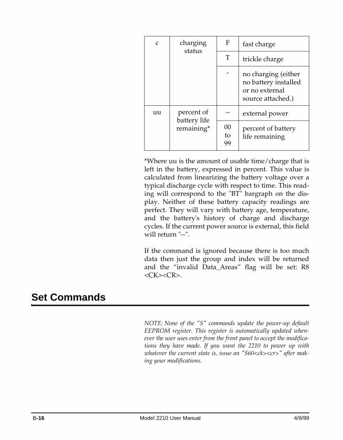
*Where uu is the amount of usable time/charge that is left in the battery, expressed in percent. This value is calculated from linearizing the battery voltage over a typical discharge cycle with respect to time. This read-ing will correspond to the "BT" bargraph on the dis-play. Neither of these battery capacity readings are perfect. They will vary with battery age, temperature, and the battery's history of charge and discharge cycles. If the current power source is external, this field will return "--".
If the command is ignored because there is too much data then just the group and index will be returned and the “invalid Data_Areas” flag will be set: R8 <CK><CR>.
Set Commands
NOTE: None of the "S" commands update the power-up default EEPROM register. This register is automatically updated when-ever the user uses enter from the front panel to accept the modifica-tions they have made. If you want the 2210 to power up with whatever the current state is, issue an "S60<ck><cr>" after mak-ing your modifications.
c charging status
F fast charge
T trickle charge
- no charging (either no battery installed or no external source attached.)
uu percent of battery life remaining*
-- external power
00 to 99
percent of battery life remaining
B-16 Model 2210 User Manual 4/9/99
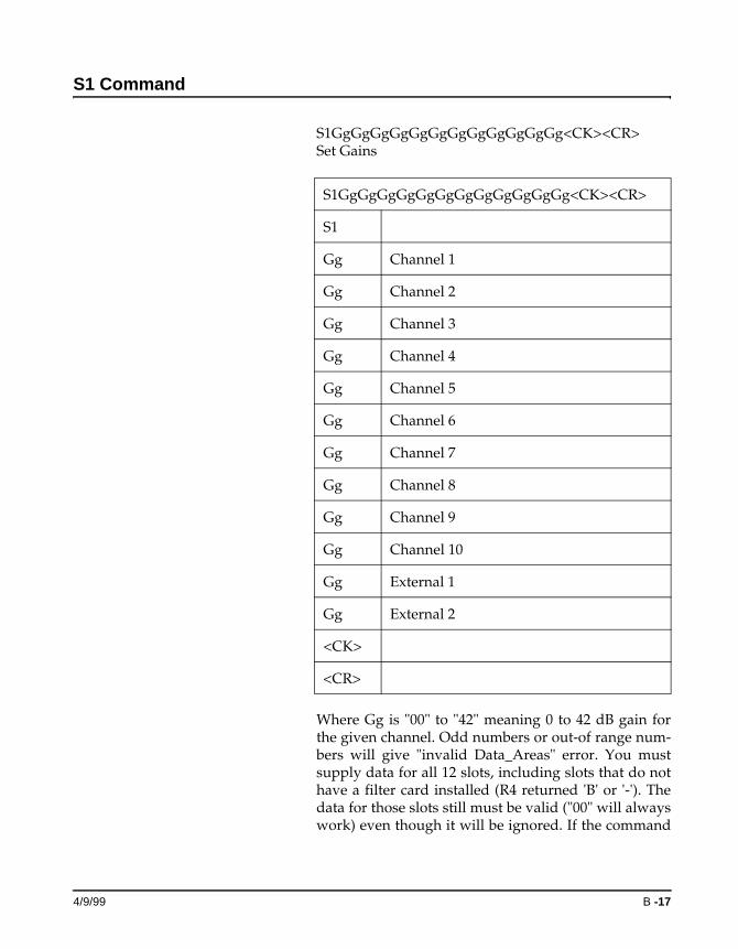
S1 Command
S1GgGgGgGgGgGgGgGgGgGgGgGg<CK><CR> Set Gains
Where Gg is "00" to "42" meaning 0 to 42 dB gain for the given channel. Odd numbers or out-of range num-bers will give "invalid Data_Areas" error. You must supply data for all 12 slots, including slots that do not have a filter card installed (R4 returned 'B' or '-'). The data for those slots still must be valid ("00" will always work) even though it will be ignored. If the command
S1GgGgGgGgGgGgGgGgGgGgGgGg<CK><CR>
S1
Gg Channel 1
Gg Channel 2
Gg Channel 3
Gg Channel 4
Gg Channel 5
Gg Channel 6
Gg Channel 7
Gg Channel 8
Gg Channel 9
Gg Channel 10
Gg External 1
Gg External 2
<CK>
<CR>
4/9/99 B -17
is executed then the complete command will be returned:
S1GgGgGgGgGgGgGgGgGgGgGgGg<CK><CR>
If the command is ignored because there is too much or too little data, or the data for one of the channels is out of range, then just the group and index will be returned and the "invalid Data_Areas" flag will be set:
S1<CK><CR>
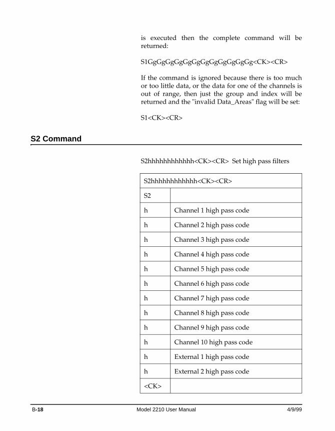
S2 Command
S2hhhhhhhhhhhh<CK><CR> Set high pass filters
S2hhhhhhhhhhhh<CK><CR>
S2
h Channel 1 high pass code
h Channel 2 high pass code
h Channel 3 high pass code
h Channel 4 high pass code
h Channel 5 high pass code
h Channel 6 high pass code
h Channel 7 high pass code
h Channel 8 high pass code
h Channel 9 high pass code
h Channel 10 high pass code
h External 1 high pass code
h External 2 high pass code
<CK>
B-18 Model 2210 User Manual 4/9/99
Where h is the high pass state for the given channel:
High pass 0 = A-Weight
High pass 1 = B-Weight
High pass 2 = C-Weight
High pass 3 = 1Hz
High pass 4 = 10Hz
High pass 5 = 20Hz
Out-of range numbers will give "invalid Data_Areas" error. You must supply data for all 12 slots, including slots that do not have a filter card installed (R4 returned 'B' or '-'). The data for those slots still must be valid ("0" will always work) even though it will be ignored. If the command is executed then the complete command will be returned:
S2hhhhhhhhhhhh<CK><CR>
If the command is ignored because there is too much or too little data, or one of the values is out of range, then just the group and index will be returned and the "invalid Data_Areas" flag will be set:
S2<CK><CR>
S3 Command
S3llllllllllll<CK><CR> Set low pass filters
<CR>
S3llllllllllll<CK><CR>
S3
l Channel 1 low pass code
4/9/99 B -19
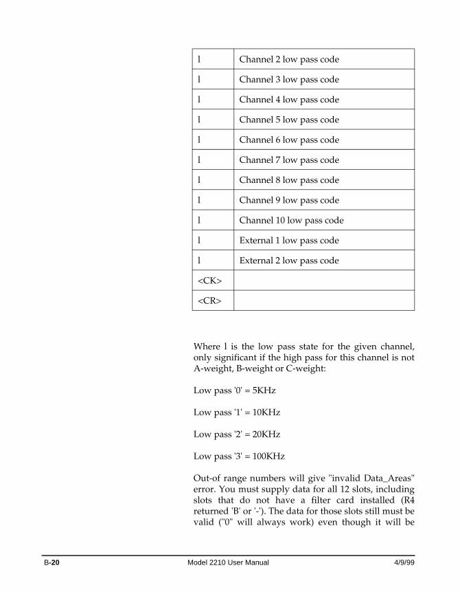
Where l is the low pass state for the given channel, only significant if the high pass for this channel is not A-weight, B-weight or C-weight:
Low pass '0' = 5KHz
Low pass '1' = 10KHz
Low pass '2' = 20KHz
Low pass '3' = 100KHz
Out-of range numbers will give "invalid Data_Areas" error. You must supply data for all 12 slots, including slots that do not have a filter card installed (R4 returned 'B' or '-'). The data for those slots still must be valid ("0" will always work) even though it will be
l Channel 2 low pass code
l Channel 3 low pass code
l Channel 4 low pass code
l Channel 5 low pass code
l Channel 6 low pass code
l Channel 7 low pass code
l Channel 8 low pass code
l Channel 9 low pass code
l Channel 10 low pass code
l External 1 low pass code
l External 2 low pass code
<CK>
<CR>
B-20 Model 2210 User Manual 4/9/99
ignored. If the command is executed then the complete command will be returned:
S3llllllllllll<CK><CR>
If the command is ignored because there is too much or too little data, or one of the values is out of range, then just the group and index will be returned and the "invalid Data_Areas" flag will be set:
S3<CK><CR>
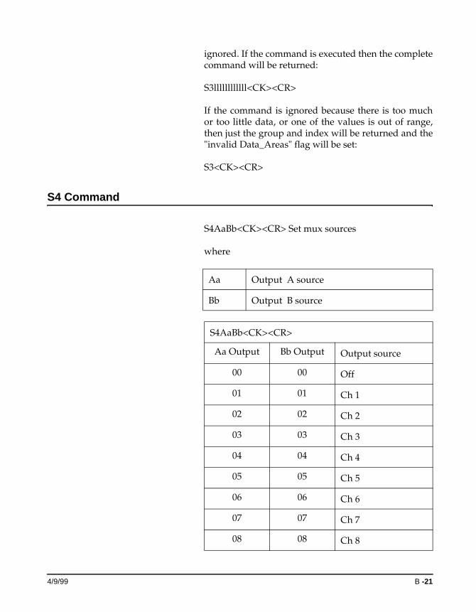
S4 Command
S4AaBb<CK><CR> Set mux sources
where
Aa Output A source
Bb Output B source
S4AaBb<CK><CR>
Aa Output Bb Output Output source
00 00 Off
01 01 Ch 1
02 02 Ch 2
03 03 Ch 3
04 04 Ch 4
05 05 Ch 5
06 06 Ch 6
07 07 Ch 7
08 08 Ch 8
4/9/99 B -21
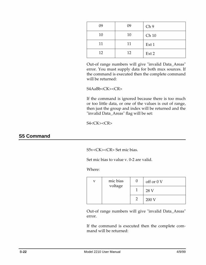
Out-of range numbers will give "invalid Data_Areas" error. You must supply data for both mux sources. If the command is executed then the complete command will be returned:
S4AaBb<CK><CR>
If the command is ignored because there is too much or too little data, or one of the values is out of range, then just the group and index will be returned and the "invalid Data_Areas" flag will be set:
S4<CK><CR>
S5 Command
S5v<CK><CR> Set mic bias.
Set mic bias to value v. 0-2 are valid.
Where:
Out-of range numbers will give "invalid Data_Areas" error.
If the command is executed then the complete com-mand will be returned:
09 09 Ch 9
10 10 Ch 10
11 11 Ext 1
12 12 Ext 2
v mic bias voltage
0 off or 0 V
1 28 V
2 200 V
B-22 Model 2210 User Manual 4/9/99
S5v<CK><CR>
If the command is ignored because there was too much or too little data or the value is out of range, then just the group and index will be returned and the "invalid Data_Areas" flag will be set:
S5<CK><CR>
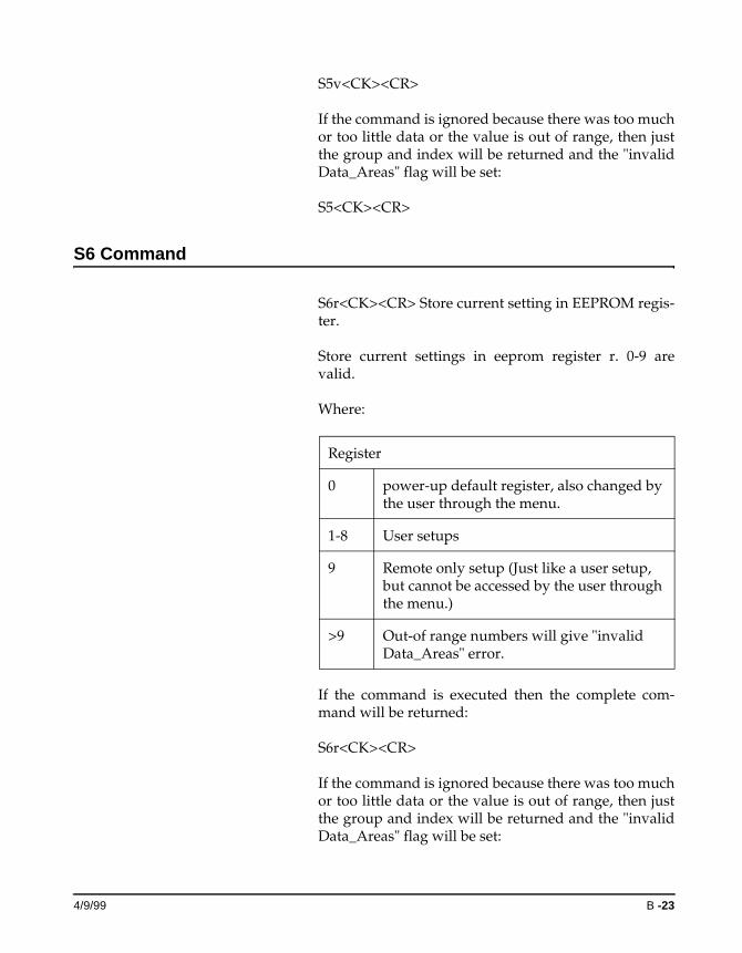
S6 Command
S6r<CK><CR> Store current setting in EEPROM regis-ter.
Store current settings in eeprom register r. 0-9 are valid.
Where:
If the command is executed then the complete com-mand will be returned:
S6r<CK><CR>
If the command is ignored because there was too much or too little data or the value is out of range, then just the group and index will be returned and the "invalid Data_Areas" flag will be set:
Register
0 power-up default register, also changed by the user through the menu.
1-8 User setups
9 Remote only setup (Just like a user setup, but cannot be accessed by the user through the menu.)
>9 Out-of range numbers will give "invalid Data_Areas" error.
4/9/99 B -23
S6<CK><CR>
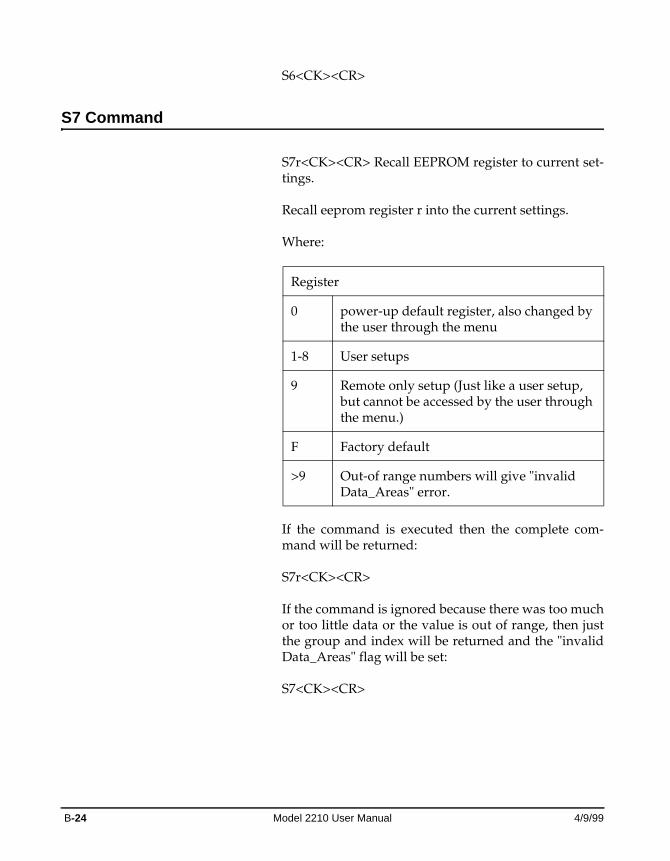
S7 Command
S7r<CK><CR> Recall EEPROM register to current set-tings.
Recall eeprom register r into the current settings.
Where:
If the command is executed then the complete com-mand will be returned:
S7r<CK><CR>
If the command is ignored because there was too much or too little data or the value is out of range, then just the group and index will be returned and the "invalid Data_Areas" flag will be set:
S7<CK><CR>
Register
0 power-up default register, also changed by the user through the menu
1-8 User setups
9 Remote only setup (Just like a user setup, but cannot be accessed by the user through the menu.)
F Factory default
>9 Out-of range numbers will give "invalid Data_Areas" error.
B-24 Model 2210 User Manual 4/9/99
Index
Numerics25-pin Signal Output Interface 2-11
AAccuracy
Type 1 1-1, 1-3Adjustable 1-3American National Standards Institute
(ANSI) 1-3Applications 1-3
BBack Panel 2-7Battery 1-3Battery Pack Compartment 2-8Battery Power Notes 2-4
CComponents 1-5Config 3-7
DData Retention 1-8
EEnvironmental Considerations 1-7External Inputs 2-10External Power Input 2-13
FFeatures 1-3Formatting Conventions 1-2Front Panel 2-1Fuses 2-12
GGetting 1-5Getting Started 1-5
Iinternal 2-8International Electrotechnical Commission
(IEC) 1-3
KKeyPad 2-5keys
functions of 2-5
MModel 1-5, 1-8Model 2210
optional equipment 1-6Model 2210 Components 1-5Multiplexer (MUX) outputs 2-10Mux 3-7
OOverload Lights 2-6Overloads 3-6
Ppower source
external 2-9
RRecall 3-5
Sserial number 1-6Store 3-6
TTen Channel Inputs 2-6Turning off the Model 2210 3-8Turning on the Model 2210 3-1Type 1 1-3
6/10/05 Index-1
Accuracy 1-1, 1-3
UUnpacking and Inspection 1-6Using Menu Items 3-2
Wwarranty 1-4
Index-2 Model 2210 User Manual 6/10/05