Embed Size (px)
Citation preview
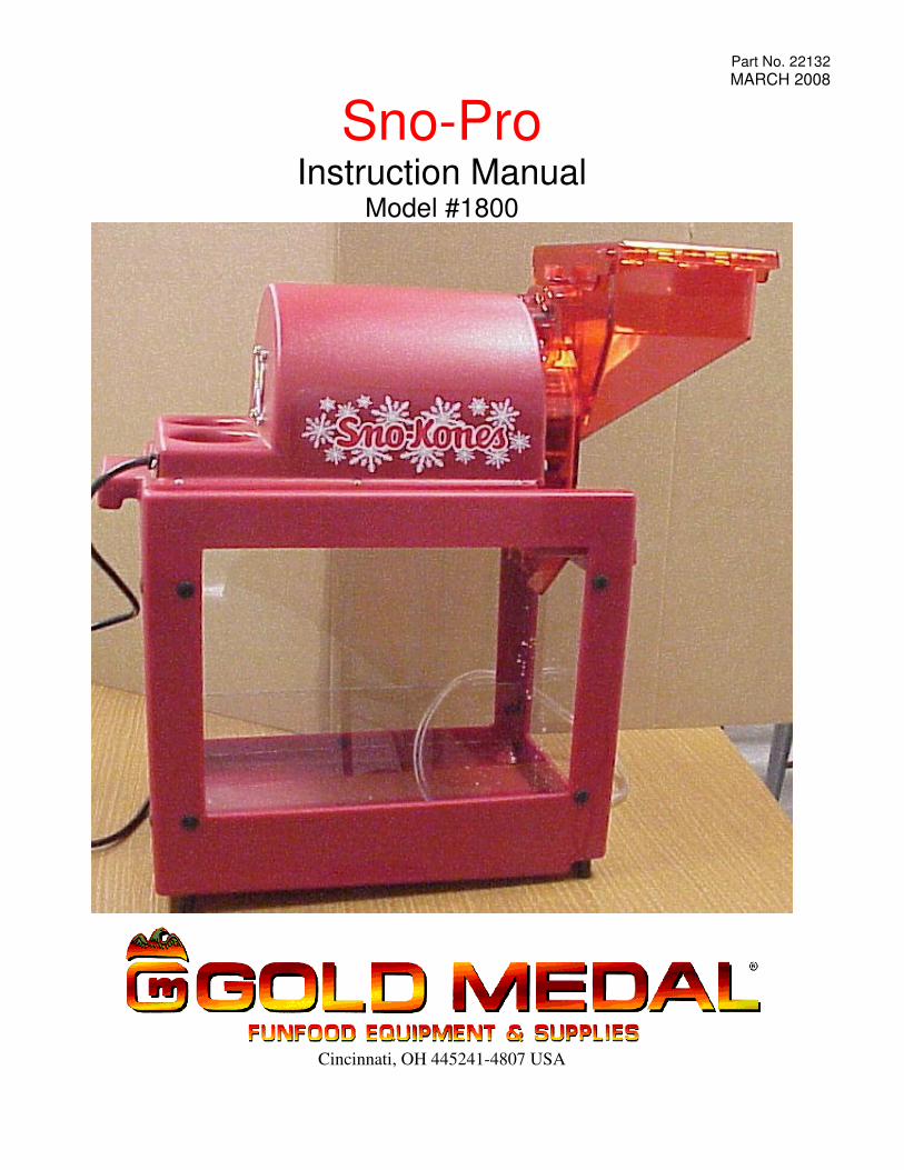
Part No. 22132 MARCH 2008
Sno-Pro Instruction Manual
Model #1800
Cincinnati, OH 445241-4807 USA

SAFETY PRECAUTIONS

Sno-Pro
All Models #1800 3
INSTALLATION
MACHINE DESCRIPTION The Sno-Pro is an automatic shaver with a tremendous capacity. You will find that it keeps up with any demand. The Sno-Pro consists of the hopper, which houses the band shaving blade, impeller, hopper lid, motor, and the ice cabinet. ELECTRICAL REQUIREMENTS The Sno-Pro operates on 120 Volt, 15 Amp, single phase, 60 cycle AC current. Be sure that your electrical supply meets this requirement. ICE REQUIREMENTS The Sno-Pro can take ice cube (small or medium in size) or small block ices, if you break the block into pieces approximately 2 to 3 inches in size. NOTE: The ice will not enter the shaving chute if the pieces are too large.
MACHINE OPERATION
Plug the power cord into the appropriate electrical outlet. TO OPERATE THE SNO-PRO 1. Open the hopper lid. Fill the hopper to within an inch of the top with ice cubes or block ice (no larger
than 2" to 3"). Close the Hopper Lid. 2. Toggle the POWER switch to the ON position. 3. Press the Red Motor Button to shave. If the hopper is open the motor will not operate. NOTE: Never allow any foreign or metallic objects around the shaver area of the Sno-Pro. Ice picks, scoops, and debris that may be in the ice often damage blades. Harder ice will result in finer now, while soft ice will result in coarser snow.

Sno-Pro
All Models #1800 4
MAINTENANCE INSTRUCTIONS
Sno-Pro
All Models #1800 5
ORDERING SPARE PARTS
1. Identify the desired part by checking it against the photos, illustrations, and/or the parts list. 2. When ordering, please include part number, part name, and quantity desired. 3. Please include your model name and machine serial number (located on the machine nameplate) with
your order. 4. Address all parts orders to:
Parts Department Gold Medal Products Co.
10700 Medallion Drive Cincinnati, Ohio 45241-4807
or, place orders at: (513) 769-7676
Fax: (513) 769-8500 E-mail: [email protected]
Sno-Pro
All Models #1800 6
INSTALLING NEW SHAVER BLADES
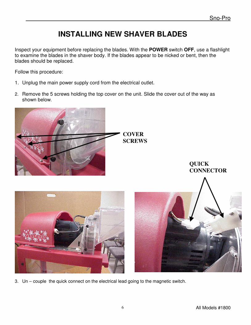
Inspect your equipment before replacing the blades. With the POWER switch OFF, use a flashlight to examine the blades in the shaver body. If the blades appear to be nicked or bent, then the blades should be replaced. Follow this procedure: 1. Unplug the main power supply cord from the electrical outlet. 2. Remove the 5 screws holding the top cover on the unit. Slide the cover out of the way as
shown below.
3. Un – couple the quick connect on the electrical lead going to the magnetic switch.
COVER SCREWS
QUICK CONNECTOR
Sno-Pro
All Models #1800 7
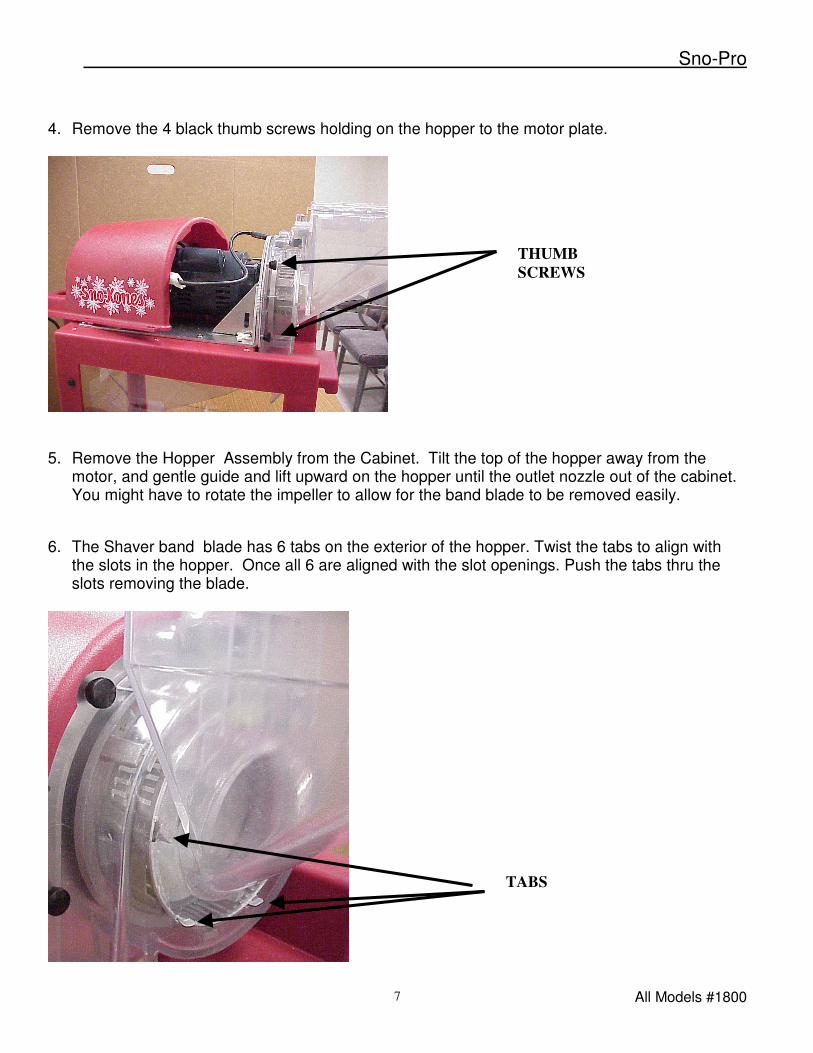
4. Remove the 4 black thumb screws holding on the hopper to the motor plate.
5. Remove the Hopper Assembly from the Cabinet. Tilt the top of the hopper away from the
motor, and gentle guide and lift upward on the hopper until the outlet nozzle out of the cabinet. You might have to rotate the impeller to allow for the band blade to be removed easily.
6. The Shaver band blade has 6 tabs on the exterior of the hopper. Twist the tabs to align with
the slots in the hopper. Once all 6 are aligned with the slot openings. Push the tabs thru the slots removing the blade.
TABS
THUMB SCREWS
Sno-Pro
All Models #1800 8
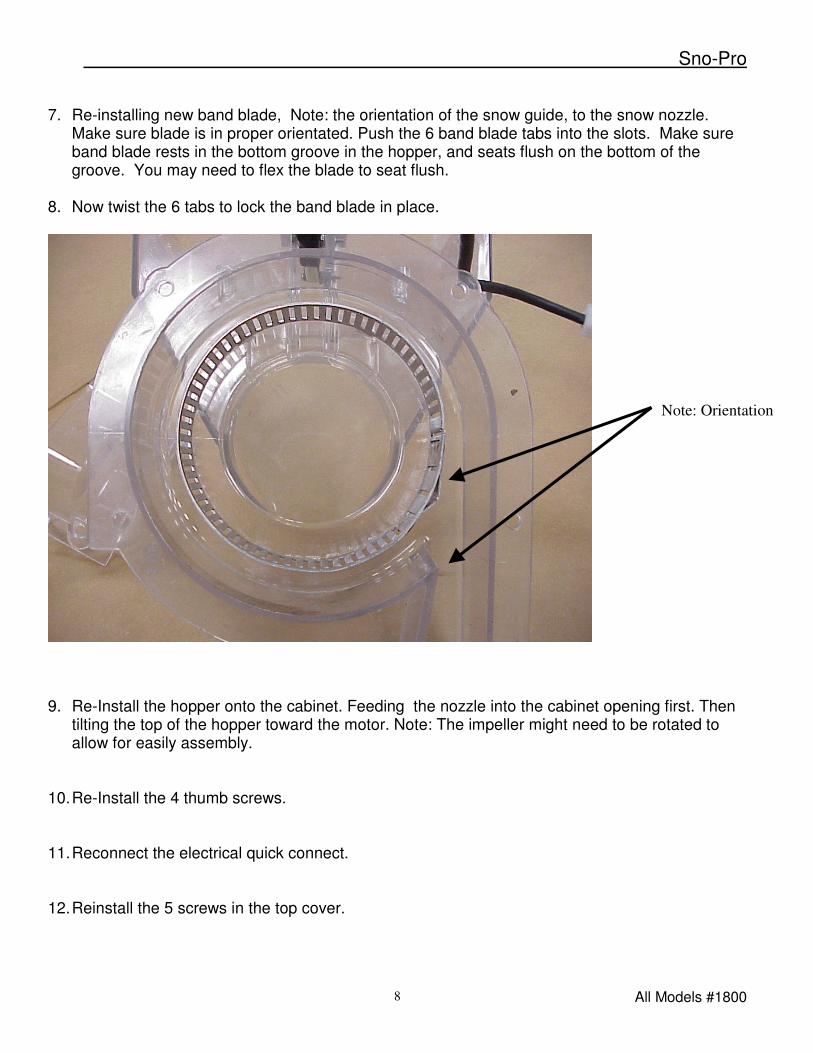
7. Re-installing new band blade, Note: the orientation of the snow guide, to the snow nozzle.
Make sure blade is in proper orientated. Push the 6 band blade tabs into the slots. Make sure band blade rests in the bottom groove in the hopper, and seats flush on the bottom of the groove. You may need to flex the blade to seat flush.
8. Now twist the 6 tabs to lock the band blade in place.
9. Re-Install the hopper onto the cabinet. Feeding the nozzle into the cabinet opening first. Then
tilting the top of the hopper toward the motor. Note: The impeller might need to be rotated to allow for easily assembly.
10. Re-Install the 4 thumb screws. 11. Reconnect the electrical quick connect. 12. Reinstall the 5 screws in the top cover.
Note: Orientation
Sno-Pro
All Models #1800 9
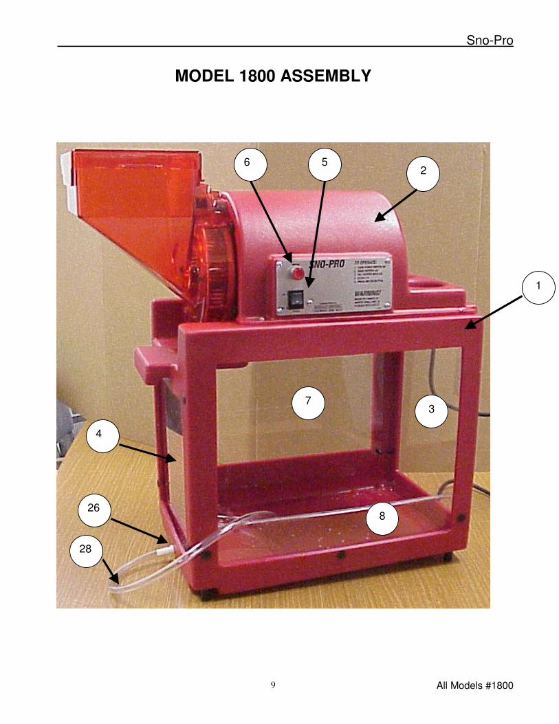
MODEL 1800 ASSEMBLY
6
1
2 5
3 7
4
8 26
28
Sno-Pro
All Models #1800 10
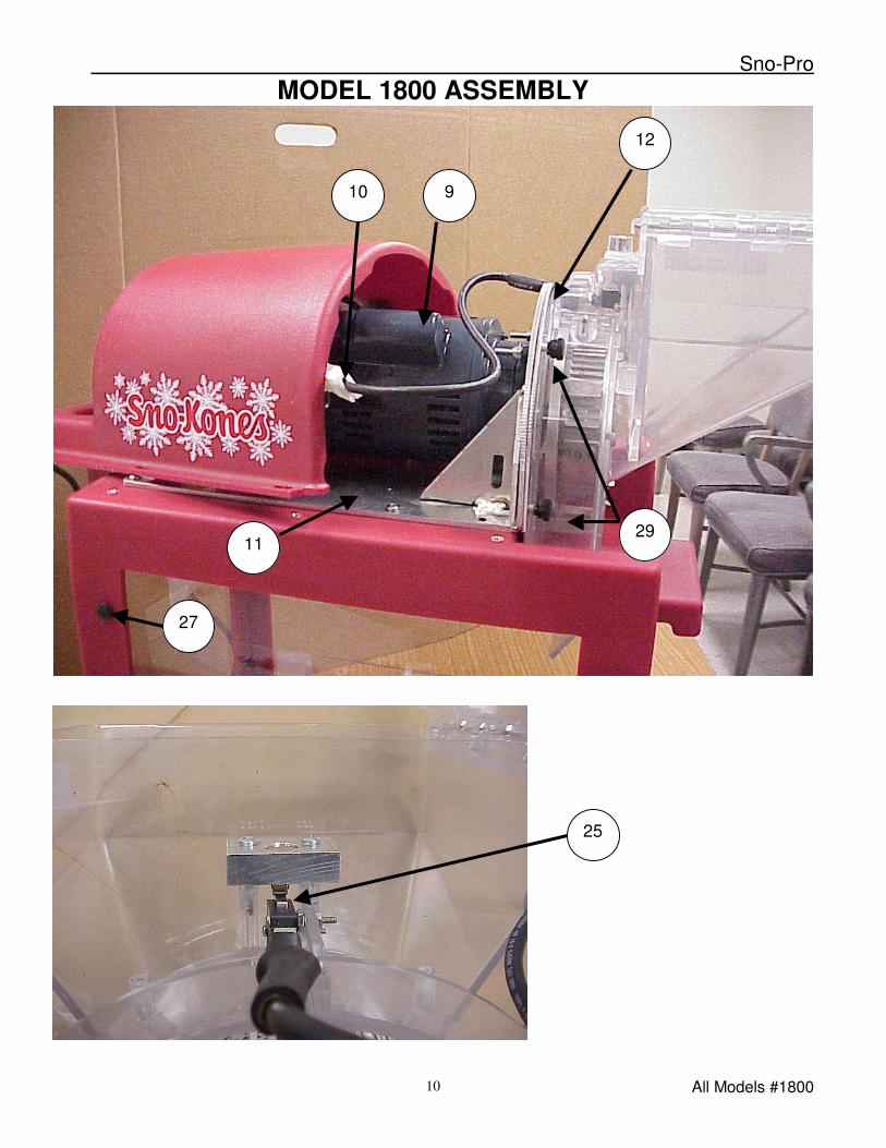
MODEL 1800 ASSEMBLY
9
12
10
11
25
27
29

Sno-Pro
All Models #1800 11
MODEL 1800 ASSEMBLY
13.
15
14
17.
16.
9.
Sno-Pro
All Models #1800 12
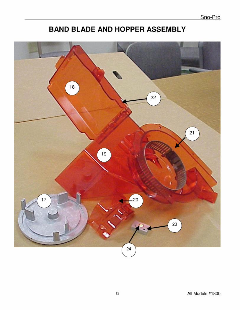
BAND BLADE AND HOPPER ASSEMBLY
18
23
19
20 17
21
22
24
Sno-Pro
All Models #1800 13
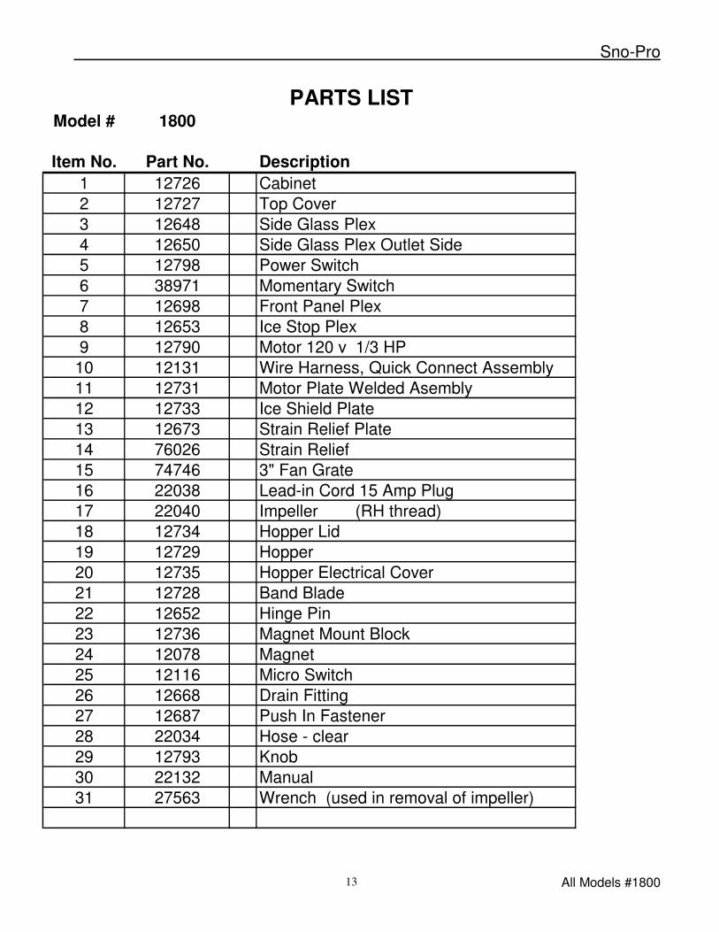
PARTS LIST
Model # 1800
Item No. Part No. Description1 12726 Cabinet2 12727 Top Cover3 12648 Side Glass Plex4 12650 Side Glass Plex Outlet Side5 12798 Power Switch6 38971 Momentary Switch7 12698 Front Panel Plex8 12653 Ice Stop Plex9 12790 Motor 120 v 1/3 HP10 12131 Wire Harness, Quick Connect Assembly11 12731 Motor Plate Welded Asembly12 12733 Ice Shield Plate13 12673 Strain Relief Plate14 76026 Strain Relief15 74746 3" Fan Grate16 22038 Lead-in Cord 15 Amp Plug17 22040 Impeller (RH thread)18 12734 Hopper Lid19 12729 Hopper20 12735 Hopper Electrical Cover21 12728 Band Blade 22 12652 Hinge Pin 23 12736 Magnet Mount Block24 12078 Magnet25 12116 Micro Switch26 12668 Drain Fitting27 12687 Push In Fastener28 22034 Hose - clear29 12793 Knob30 22132 Manual31 27563 Wrench (used in removal of impeller)
Sno-Pro
All Models #1800 14
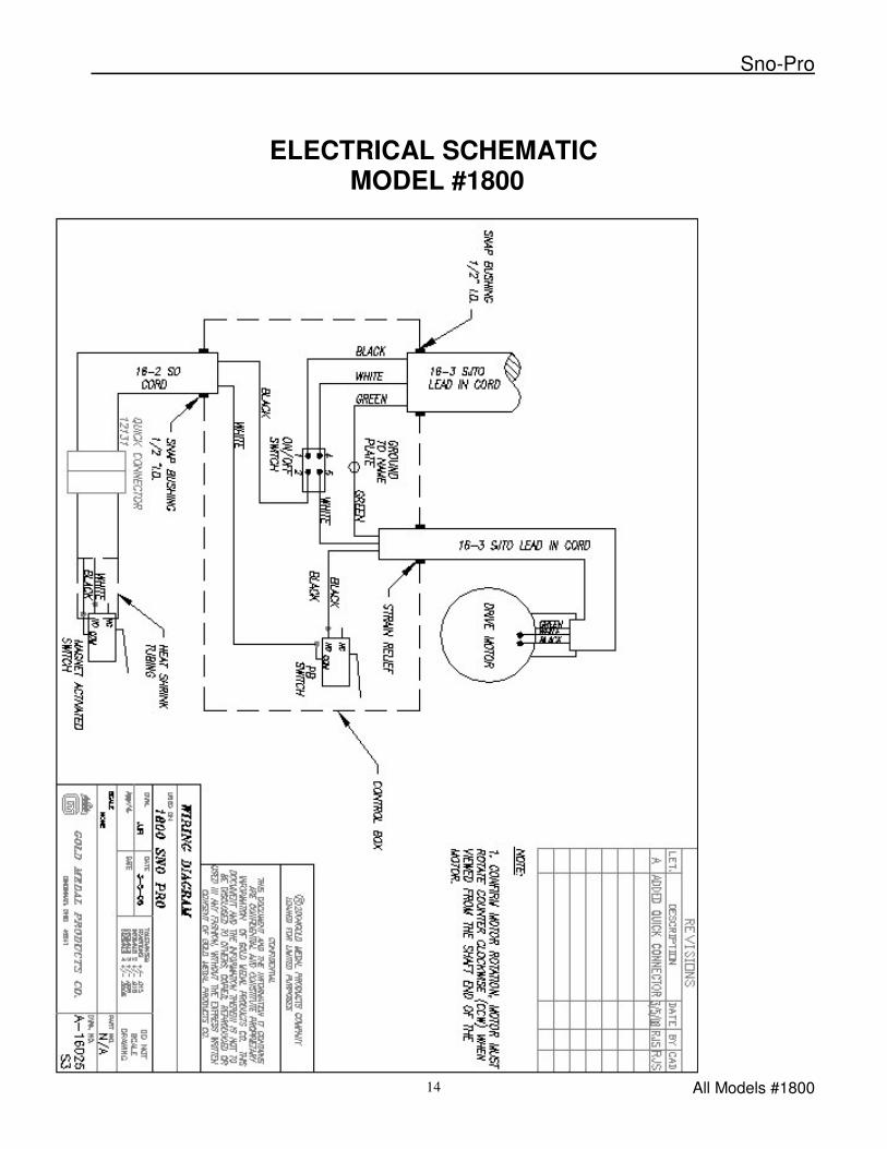
ELECTRICAL SCHEMATIC MODEL #1800
Sno-Pro
All Models #1800 15
WARRANTY
WE WARRANT to the original purchaser the Gold Medal equipment sold by us to be free from defects in material or workmanship under normal use and service. Our obligation under this warranty shall be limited to the repair or replacement of any defective part for a period of six (6) months from the date of sale to the Original Purchaser with regard to labor and two (2) years with regard to parts and does not cover damage to the equipment caused by accident, alteration, improper use, voltage, abuse, or failure to follow instructions. THIS WARRANTY IS IN LIEU OF ALL OTHER WARRANTIES EXPRESSED OR IMPLIED, AND OF ALL OTHER OBLIGATIONS OR LIABILITIES ON OUR PART, INCLUDING THE IMPLIED WARRANTY OF MERCHANTIBILITY. THERE ARE NO WARRANTIES WHICH EXTEND BEYOND THE DESCRIPTION ON THE FACE HEREOF. We neither assume, nor authorize any other person to assume for us, any other obligation or liability in connection with the sale of said GOLD MEDAL equipment or any part thereof. The term “Original Purchaser” as used in this warranty shall be deemed to mean that person, firm, association, or corporation who was billed by the GOLD MEDAL PRODUCTS COMPANY, or their authorized distributor for the equipment. THIS WARRANTY HAS NO EFFECT AND IS VOID UNLESS THE ORIGINAL PURCHASER FIRST CALLS GOLD MEDAL PRODUCTS COMPANY AT 1-800- 543-0862 TO DISCUSS WITH OUR SERVICE REPRESENTATIVE THE EQUIPMENT PROBLEM, AND, IF NECESSARY, FOR INSTRUCTIONS CONCERNING THE REPAIR OR REPLACEMENT OF PARTS. NOTE: This equipment is manufactured and sold for commercial use only.
GOLD MEDAL PRODUCTS COMPANY 10700 Medallion Drive Cincinnati, Ohio 45241-4807 USA