Embed Size (px)
Citation preview
7/30/2019 22301937-Tuneup-6-Cyl
http://slidepdf.com/reader/full/22301937-tuneup-6-cyl 1/13
TUNE-UP - 6-CYL
1988 Jeep Cherokee
1987-88 TUNE-UPJeep 6 Cylinder Tune-Up
Cherokee, Comanche, Wagoneer, Wrangler
IDENTIFICATION
ENGINE IDENTIFICATION
Engine can be identified by the fourth character of engineBuild Date Code number, located on a tag attached to right side ofblock between No. 2 and 3 cylinders.
The same code letter is also the fourth character in theVehicle Identification Number (VIN), located at top left corner of
dashboard.
ENGINE CODE TABLE¡ ¡ ¡ ¡ ¡ ¡ ¡ ¡ ¡ ¡ ¡ ¡ ¡ ¡ ¡ ¡ ¡ ¡ ¡ ¡ ¡ ¡ ¡ ¡ ¡ ¡ ¡ ¡ ¡ ¡ ¡ ¡ ¡ ¡ ¡ ¡
Engine Code
4.0L (242") MPFI ....................................... M4.2L (258") 2-Bbl. ..................................... C
¡ ¡ ¡ ¡ ¡ ¡ ¡ ¡ ¡ ¡ ¡ ¡ ¡ ¡ ¡ ¡ ¡ ¡ ¡ ¡ ¡ ¡ ¡ ¡ ¡ ¡ ¡ ¡ ¡ ¡ ¡ ¡ ¡ ¡ ¡ ¡
TUNE-UP NOTES
NOTE: When performing tune-up procedures described in thisarticle, these notes and precautions must be followed.
Due to late changes and corrections, always refer to EmissionControl Label in engine compartment before attempting tune-up. Ifmanual and label specifications differ, use label specifications.
When performing tune-up on vehicles equipped with a catalyticconverter, do not allow or create an engine misfire in one or morecylinders for an extended period of time. Damage to converter fromoverheating may occur due to loading with unburned fuel.
TESTING
ENGINE COMPRESSION
Check compression pressure with engine at normal operatingtemperature, all spark plugs removed, throttle and choke valves wideopen and engine at cranking speed.
COMPRESSION SPECIFICATIONS TABLE¡ ¡ ¡ ¡ ¡ ¡ ¡ ¡ ¡ ¡ ¡ ¡ ¡ ¡ ¡ ¡ ¡ ¡ ¡ ¡ ¡ ¡ ¡ ¡ ¡ ¡ ¡ ¡ ¡ ¡ ¡ ¡ ¡ ¡ ¡ ¡
Application Specification
Compression Ratio .................................. 9.2:1Compression Pressure ....... 120-150 psi (8.4-10.5 kg/cm
¢
)Maximum Variation Between Cylinders .. 30 psi (2.1 kg/cm
¢
)¡ ¡ ¡ ¡ ¡ ¡ ¡ ¡ ¡ ¡ ¡ ¡ ¡ ¡ ¡ ¡ ¡ ¡ ¡ ¡ ¡ ¡ ¡ ¡ ¡ ¡ ¡ ¡ ¡ ¡ ¡ ¡ ¡ ¡ ¡ ¡
HIGH TENSION WIRE RESISTANCE
Do not puncture spark plug wires with any type of probe.Remove spark plug wire and check resistance using an ohmmeter.
7/30/2019 22301937-Tuneup-6-Cyl
http://slidepdf.com/reader/full/22301937-tuneup-6-cyl 2/13
SPARK PLUGS
SPARK PLUG TYPE TABLE¡ ¡ ¡ ¡ ¡ ¡ ¡ ¡ ¡ ¡ ¡ ¡ ¡ ¡ ¡ ¡ ¡ ¡ ¡ ¡ ¡ ¡ ¡ ¡ ¡ ¡ ¡ ¡ ¡ ¡
Application Champion No.
All Models ....................................... RFN14LY¡ ¡ ¡ ¡ ¡ ¡ ¡ ¡ ¡ ¡ ¡ ¡ ¡ ¡ ¡ ¡ ¡ ¡ ¡ ¡ ¡ ¡ ¡ ¡ ¡ ¡ ¡ ¡ ¡ ¡
SPARK PLUG SPECIFICATIONS TABLE¡ ¡ ¡ ¡ ¡ ¡ ¡ ¡ ¡ ¡ ¡ ¡ ¡ ¡ ¡ ¡ ¡ ¡ ¡ ¡ ¡ ¡ ¡ ¡ ¡ ¡ ¡ ¡ ¡ ¡
Gap: In. (mm) Torque: Ft. Lbs. (N.m)
0.035 (0.89) ................................ 7-15 (10-20)¡ ¡ ¡ ¡ ¡ ¡ ¡ ¡ ¡ ¡ ¡ ¡ ¡ ¡ ¡ ¡ ¡ ¡ ¡ ¡ ¡ ¡ ¡ ¡ ¡ ¡ ¡ ¡ ¡ ¡
FUEL PUMP
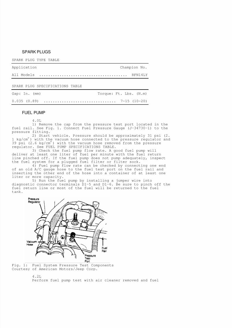
4.0L1) Remove the cap from the pressure test port located in the
fuel rail. See Fig. 1. Connect Fuel Pressure Gauge (J-34730-1) to thepressure fitting.
2) Start vehicle. Pressure should be approximately 31 psi (2.1 kg/cm
¢
) with the vacuum hose connected to the pressure regulator and39 psi (2.6 kg/cm
¢
) with the vacuum hose removed from the pressureregulator. See FUEL PUMP SPECIFICATIONS TABLE.
3) Check the fuel pump flow rate. A good fuel pump willdeliver at least one liter of fuel per minute with the fuel returnline pinched off. If the fuel pump does not pump adequately, inspectthe fuel system for a plugged fuel filter or filter sock.
4) Fuel pump flow rate can be checked by connecting one endof an old A/C gauge hose to the fuel test port on the fuel rail and
inserting the other end of the hose into a container of at least oneliter or more capacity.
5) Run the fuel pump by installing a jumper wire intodiagnostic connector terminals D1-5 and D1-6. Be sure to pinch off thefuel return line or most of the fuel will be returned to the fueltank.
Fig. 1: Fuel System Pressure Test ComponentsCourtesy of American Motors/Jeep Corp.
4.2LPerform fuel pump test with air cleaner removed and fuel
7/30/2019 22301937-Tuneup-6-Cyl
http://slidepdf.com/reader/full/22301937-tuneup-6-cyl 3/13
inlet line or filter disconnected at carburetor. Disconnect fuelreturn line at fuel filter and plug nipple on filter. Make all testsat idle speed. See FUEL PUMP SPECIFICATIONS TABLE.
FUEL PUMP SPECIFICATIONS TABLE¡ ¡ ¡ ¡ ¡ ¡ ¡ ¡ ¡ ¡ ¡ ¡ ¡ ¡ ¡ ¡ ¡ ¡ ¡ ¡ ¡ ¡ ¡ ¡ ¡ ¡ ¡ ¡ ¡ ¡ ¡ ¡ ¡ ¡
Application Pressure Volume** psi (kg/cm
¢
) (1) Pts. (L)
4.0L .................... (2) 31 (2.1) ............ 1.0 (.47)4.0L .................... (3) 39 (2.6) ............ 1.0 (.47)4.2L .................. 4.0-5.0 (.28-.35) ......... 1.0 (.47)
(1) - Volume per 30 seconds.(2) - With the vacuum hose connected to the pressure regulator.(3) - With the vacuum hose removed from the pressure regulator.
¡ ¡ ¡ ¡ ¡ ¡ ¡ ¡ ¡ ¡ ¡ ¡ ¡ ¡ ¡ ¡ ¡ ¡ ¡ ¡ ¡ ¡ ¡ ¡ ¡ ¡ ¡ ¡ ¡ ¡
ADJUSTMENTS
VALVE ARRANGEMENT
* E-I-I-E-I-E-E-I-E-I-I-E (Front-to-rear).
VALVE CLEARANCE
All engines are equipped with hydraulic lifters. Valveclearance is not adjustable.
IGNITION COIL WIRE
Remove ignition coil wire from coil and distributor cap.
Check terminals for corrosion and clean (if necessary). Check coilwire resistance. Replace wire if resistance is excessive.
HIGH TENSION WIRE RESISTANCE (OHMS) TABLE¡ ¡ ¡ ¡ ¡ ¡ ¡ ¡ ¡ ¡ ¡ ¡ ¡ ¡ ¡ ¡ ¡ ¡ ¡ ¡ ¡ ¡ ¡ ¡ ¡ ¡ ¡ ¡ ¡ ¡
Wire Length Minimum Maximum
0-15" .................. 3000 ................... 10,00015-25" ................. 4000 ................... 15,00025-35" ................. 6000 ................... 20,000Over 35" ............... 8000 ................... 25,000
¡ ¡ ¡ ¡ ¡ ¡ ¡ ¡ ¡ ¡ ¡ ¡ ¡ ¡ ¡ ¡ ¡ ¡ ¡ ¡ ¡ ¡ ¡ ¡ ¡ ¡ ¡ ¡ ¡ ¡
DISTRIBUTOR
4.0LInformation not available from manufacturer.
4.2LAll models are equipped with Motorcraft Solid State Ignition
(SSI) systems. No adjustments are required.
7/30/2019 22301937-Tuneup-6-Cyl
http://slidepdf.com/reader/full/22301937-tuneup-6-cyl 4/13
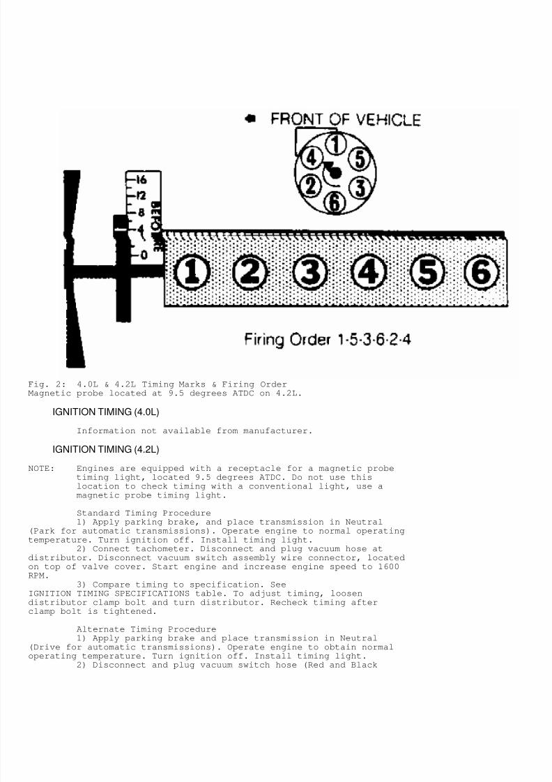
Fig. 2: 4.0L & 4.2L Timing Marks & Firing OrderMagnetic probe located at 9.5 degrees ATDC on 4.2L.
IGNITION TIMING (4.0L)
Information not available from manufacturer.
IGNITION TIMING (4.2L)
NOTE: Engines are equipped with a receptacle for a magnetic probetiming light, located 9.5 degrees ATDC. Do not use thislocation to check timing with a conventional light, use amagnetic probe timing light.
Standard Timing Procedure1) Apply parking brake, and place transmission in Neutral
(Park for automatic transmissions). Operate engine to normal operatingtemperature. Turn ignition off. Install timing light.
2) Connect tachometer. Disconnect and plug vacuum hose atdistributor. Disconnect vacuum switch assembly wire connector, locatedon top of valve cover. Start engine and increase engine speed to 1600RPM.
3) Compare timing to specification. SeeIGNITION TIMING SPECIFICATIONS table. To adjust timing, loosendistributor clamp bolt and turn distributor. Recheck timing afterclamp bolt is tightened.
Alternate Timing Procedure1) Apply parking brake and place transmission in Neutral
(Drive for automatic transmissions). Operate engine to obtain normaloperating temperature. Turn ignition off. Install timing light.
2) Disconnect and plug vacuum switch hose (Red and Black
7/30/2019 22301937-Tuneup-6-Cyl
http://slidepdf.com/reader/full/22301937-tuneup-6-cyl 5/13
wires connected to switch). Disconnect distributor vacuum advance hoseand connect hose to vacuum switch. Disconnect wire connector fromknock sensor, located in cylinder head.
3) Using a jumper wire, ground knock sensor wire connector toengine block. Start engine. With engine at idle speed (solenoidenergized), check timing. Adjust timing to one degree more thanspecification (if required). See Emission Control Label.
IGNITION TIMING SPECIFICATIONS (DEGREES BTDC@RPM) - 4.2L¡ ¡ ¡ ¡ ¡ ¡ ¡ ¡ ¡ ¡ ¡ ¡ ¡ ¡ ¡ ¡ ¡ ¡ ¡ ¡ ¡ ¡ ¡ ¡ ¡ ¡ ¡ ¡ ¡ ¡
Application Man. Trans. Auto. Trans.
50 State ............. 9 @ 1600 ............... 9 @ 1600High Altitude ........ 16 @ 1600 ............. 16 @ 1600
¡ ¡ ¡ ¡ ¡ ¡ ¡ ¡ ¡ ¡ ¡ ¡ ¡ ¡ ¡ ¡ ¡ ¡ ¡ ¡ ¡ ¡ ¡ ¡ ¡ ¡ ¡ ¡ ¡ ¡
HOT (SLOW) IDLE RPM
4.0L1) Apply parking brake and place transmission in Neutral
(Drive for automatic transmissions). Operate engine to normaloperating temperature. Turn ignition off.
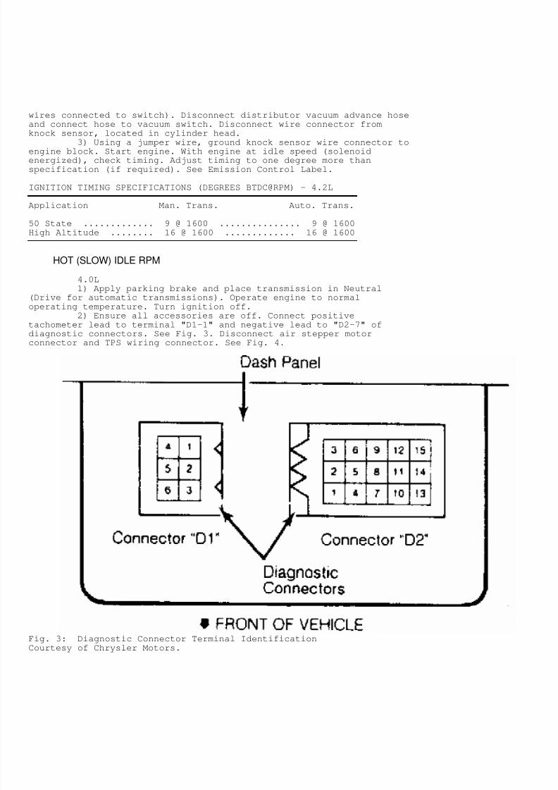
2) Ensure all accessories are off. Connect positivetachometer lead to terminal "D1-1" and negative lead to "D2-7" ofdiagnostic connectors. See Fig. 3. Disconnect air stepper motorconnector and TPS wiring connector. See Fig. 4.
Fig. 3: Diagnostic Connector Terminal IdentificationCourtesy of Chrysler Motors.
7/30/2019 22301937-Tuneup-6-Cyl
http://slidepdf.com/reader/full/22301937-tuneup-6-cyl 6/13
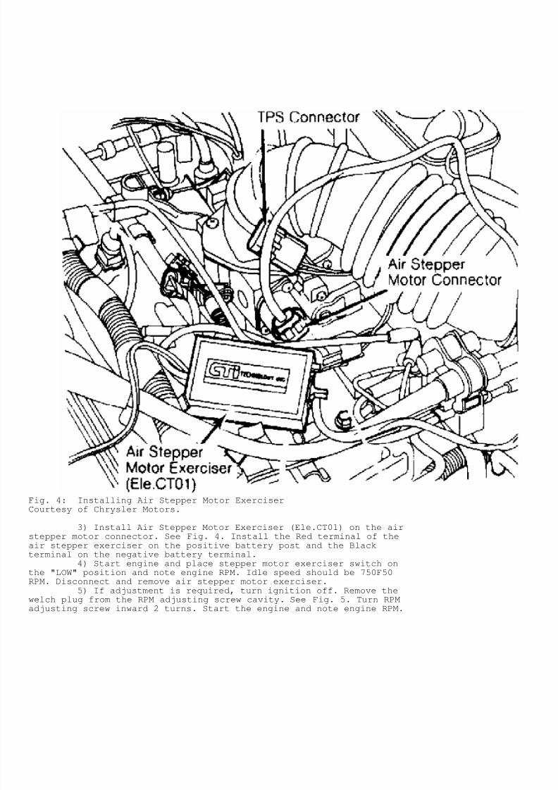
Fig. 4: Installing Air Stepper Motor ExerciserCourtesy of Chrysler Motors.
3) Install Air Stepper Motor Exerciser (Ele.CT01) on the airstepper motor connector. See Fig. 4. Install the Red terminal of theair stepper exerciser on the positive battery post and the Black
terminal on the negative battery terminal.4) Start engine and place stepper motor exerciser switch on
the "LOW" position and note engine RPM. Idle speed should be 750F50RPM. Disconnect and remove air stepper motor exerciser.
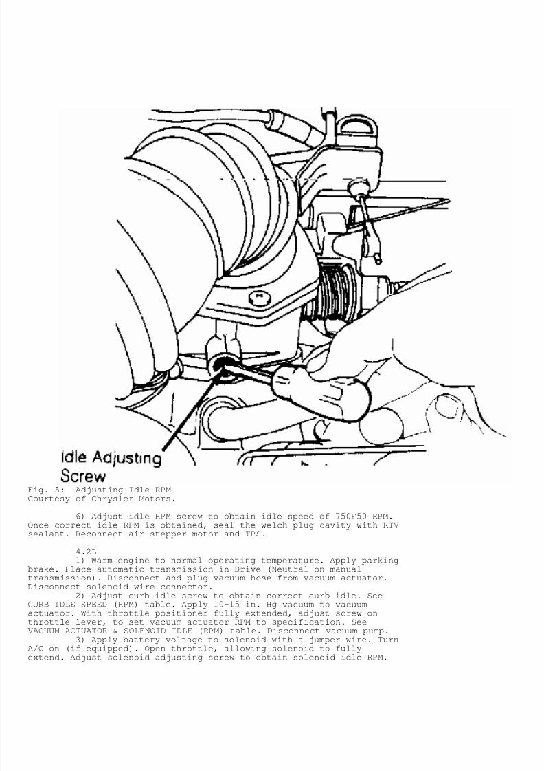
5) If adjustment is required, turn ignition off. Remove thewelch plug from the RPM adjusting screw cavity. See Fig. 5. Turn RPMadjusting screw inward 2 turns. Start the engine and note engine RPM.
7/30/2019 22301937-Tuneup-6-Cyl
http://slidepdf.com/reader/full/22301937-tuneup-6-cyl 7/13
Fig. 5: Adjusting Idle RPMCourtesy of Chrysler Motors.
6) Adjust idle RPM screw to obtain idle speed of 750F50 RPM.Once correct idle RPM is obtained, seal the welch plug cavity with RTVsealant. Reconnect air stepper motor and TPS.
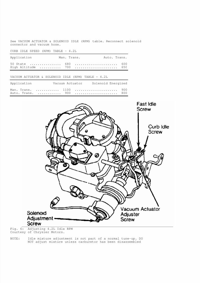
4.2L1) Warm engine to normal operating temperature. Apply parking
brake. Place automatic transmission in Drive (Neutral on manualtransmission). Disconnect and plug vacuum hose from vacuum actuator.Disconnect solenoid wire connector.
2) Adjust curb idle screw to obtain correct curb idle. SeeCURB IDLE SPEED (RPM) table. Apply 10-15 in. Hg vacuum to vacuumactuator. With throttle positioner fully extended, adjust screw onthrottle lever, to set vacuum actuator RPM to specification. SeeVACUUM ACTUATOR & SOLENOID IDLE (RPM) table. Disconnect vacuum pump.
3) Apply battery voltage to solenoid with a jumper wire. TurnA/C on (if equipped). Open throttle, allowing solenoid to fullyextend. Adjust solenoid adjusting screw to obtain solenoid idle RPM.
7/30/2019 22301937-Tuneup-6-Cyl
http://slidepdf.com/reader/full/22301937-tuneup-6-cyl 8/13
See VACUUM ACTUATOR & SOLENOID IDLE (RPM) table. Reconnect solenoidconnector and vacuum hose.
CURB IDLE SPEED (RPM) TABLE - 4.2L¡ ¡ ¡ ¡ ¡ ¡ ¡ ¡ ¡ ¡ ¡ ¡ ¡ ¡ ¡ ¡ ¡ ¡ ¡ ¡ ¡ ¡ ¡ ¡ ¡ ¡ ¡ ¡ ¡ ¡
Application Man. Trans. Auto. Trans.
50 State ................ 680 ...................... 600High Altitude ........... 700 ...................... 650
¡ ¡ ¡ ¡ ¡ ¡ ¡ ¡ ¡ ¡ ¡ ¡ ¡ ¡ ¡ ¡ ¡ ¡ ¡ ¡ ¡ ¡ ¡ ¡ ¡ ¡ ¡ ¡ ¡ ¡
VACUUM ACTUATOR & SOLENOID IDLE (RPM) TABLE - 4.2L¡ ¡ ¡ ¡ ¡ ¡ ¡ ¡ ¡ ¡ ¡ ¡ ¡ ¡ ¡ ¡ ¡ ¡ ¡ ¡ ¡ ¡ ¡ ¡ ¡ ¡ ¡ ¡ ¡ ¡
Application Vacuum Actuator Solenoid Energized
Man. Trans. ............ 1100 ...................... 900Auto. Trans. ............ 900 ...................... 800
¡ ¡ ¡ ¡ ¡ ¡ ¡ ¡ ¡ ¡ ¡ ¡ ¡ ¡ ¡ ¡ ¡ ¡ ¡ ¡ ¡ ¡ ¡ ¡ ¡ ¡ ¡ ¡ ¡ ¡
Fig. 6: Adjusting 4.2L Idle RPMCourtesy of Chrysler Motors.
NOTE: Idle mixture adjustment is not part of a normal tune-up. DONOT adjust mixture unless carburetor has been disassembled
7/30/2019 22301937-Tuneup-6-Cyl
http://slidepdf.com/reader/full/22301937-tuneup-6-cyl 9/13
or vehicle fails emissions testing.
IDLE MIXTURE (TACHOMETER (LEAN DROP) PROCEDURE)NOTE: On 4.2L engines, ensure idle speed and timing are set prior
to adjusting the idle mixture. If mixture adjustment timeexceeds 3 minutes, run engine at 2000 RPM in Neutral for oneminute, and resume adjustment. On 4.0L engines, idle mixtureadjustment is not possible.
4.2L1) Remove carburetor and locate roll pins blocking idle
mixture screws. Drill through throttle body on closed end of roll pinhole. Drive pins out with punch. Reinstall carburetor. Installtachometer.
2) Operate engine to normal operating temperature, and adjustcurb idle speed. Place automatic transmission selector in Drive(Neutral for manual transmissions). Turn mixture screws inward until
RPM drops. Turn screws outward until highest RPM is reached.3) Turn mixture screws inward to obtain the correct decrease
in RPM. See LEAN DROP (RPM) table. Adjust both screws equally. Whenmixture is correctly adjusted, replace roll pin to block adjustmentscrews.
NOTE: If final RPM differs more than 30 RPM from specified curbidle speed, reset curb idle, and repeat mixture adjustment.
LEAN DROP (RPM) TABLE¡ ¡ ¡ ¡ ¡ ¡ ¡ ¡ ¡ ¡ ¡ ¡ ¡ ¡ ¡ ¡ ¡ ¡ ¡ ¡ ¡ ¡ ¡ ¡ ¡ ¡ ¡ ¡ ¡ ¡
Application Man. Trans. Auto. Trans.
4.2L .................... 50 ........................ 50¡ ¡ ¡ ¡ ¡ ¡ ¡ ¡ ¡ ¡ ¡ ¡ ¡ ¡ ¡ ¡ ¡ ¡ ¡ ¡ ¡ ¡ ¡ ¡ ¡ ¡ ¡ ¡ ¡ ¡
THROTTLE POSITION SENSOR (TPS)
NOTE: Adjustment of TPS only applies to the 4.0L models. It may benecessary to remove throttle body from intake manifold, toaccess sensor wiring harness.
Checking & Adjusting - 4.0L (Automatic Transmission)1) Locate the square TPS connector. Note connector terminal
identification stamped on the back of the connector. Turn ignition on.2) Connect voltmeter through back of wiring harness
connector. Connect negative voltmeter lead to terminal "D" andpositive voltmeter lead to terminal "A" to check input voltage. DO NOTdisconnect TPS connector.
3) Hold throttle plate closed against idle stop and note
voltage. Input voltage should be approximately 5 volts. Disconnectvoltmeter positive lead and connect to terminal "B" to measure outputvoltage.
4) With throttle plate closed, measure the output voltage.The output voltage should be approximately 4.2 volts. If outputvoltage is not within specification, loosen TPS retaining screws.
5) Partially tighten one retaining screw. Rotate TPS toobtain correct output voltage. Tighten retaining screws once correctvoltage is obtained.
Checking & Adjusting - 4.0L (Manual Transmission)1) Turn ignition on. Connect voltmeter through back of wiring
harness connector. Connect negative voltmeter lead to terminal"B" and positive voltmeter lead to terminal "A". DO NOT disconnect TPSconnector.
7/30/2019 22301937-Tuneup-6-Cyl
http://slidepdf.com/reader/full/22301937-tuneup-6-cyl 10/13
2) Hold throttle plate in the closed throttle positionagainst idle stop and note input voltage reading. Input voltage shouldbe approximately 5.0 volts.
3) Disconnect positive lead from terminal "A" and connect toterminal "C" to check output voltage. Output voltage should be checkedwith throttle plates fully closed.
4) Output voltage should be approximately 0.8 volts. Ifoutput voltage is not within specification, loosen TPS bottomretaining screw and pivot sensor for a large adjustment or topretaining screw for a fine adjustment.
5) Adjust sensor to obtain correct output voltage. Tightenretaining screws. Remove voltmeter.
COLD (FAST) IDLE RPM
4.2LDisconnect and plug EGR valve vacuum hose. With engine
running at normal operating temperature, place fast idle screw on
second step of fast idle cam and against shoulder of high step. Turnscrew to adjust fast idle speed.
FAST IDLE SPEED (RPM) TABLE¡ ¡ ¡ ¡ ¡ ¡ ¡ ¡ ¡ ¡ ¡ ¡ ¡ ¡ ¡ ¡ ¡ ¡ ¡ ¡ ¡ ¡ ¡ ¡ ¡ ¡ ¡ ¡ ¡ ¡
Application Man. Trans. Auto. Trans.
4.2L ................... 1700 ..................... 1700¡ ¡ ¡ ¡ ¡ ¡ ¡ ¡ ¡ ¡ ¡ ¡ ¡ ¡ ¡ ¡ ¡ ¡ ¡ ¡ ¡ ¡ ¡ ¡ ¡ ¡ ¡ ¡ ¡ ¡
AUTOMATIC CHOKE SETTING
Choke coil cover is riveted in place and no adjustment isnecessary or possible.
SERVICING
EMISSION CONTROL
See EMISSIONS section.
SPECIFICATIONS
IGNITION
DistributorAll vehicles use a Motorcraft breakerless solid state
distributor.
PICK-UP COIL RESISTANCE TABLE - OHMS @ 75£
F (24£
C)¡ ¡ ¡ ¡ ¡ ¡ ¡ ¡ ¡ ¡ ¡ ¡ ¡ ¡ ¡ ¡ ¡ ¡ ¡ ¡ ¡ ¡ ¡ ¡ ¡ ¡ ¡ ¡ ¡ ¡
Application Specification
All Models ....................................... 400-800¡ ¡ ¡ ¡ ¡ ¡ ¡ ¡ ¡ ¡ ¡ ¡ ¡ ¡ ¡ ¡ ¡ ¡ ¡ ¡ ¡ ¡ ¡ ¡ ¡ ¡ ¡ ¡ ¡ ¡
TOTAL SPARK ADVANCE TABLE @ 2000 RPM¡ ¡ ¡ ¡ ¡ ¡ ¡ ¡ ¡ ¡ ¡ ¡ ¡ ¡ ¡ ¡ ¡ ¡ ¡ ¡ ¡ ¡ ¡ ¡ ¡ ¡ ¡ ¡ ¡ ¡
Application W/ Vac. Advance W/O Vac. Advance
4.0L ................ N/A .......................... N/A4.2L ............... 30.5
£
................... 7.5-12.5£
7/30/2019 22301937-Tuneup-6-Cyl
http://slidepdf.com/reader/full/22301937-tuneup-6-cyl 11/13
(1) - Information not available from manufacturer.¡ ¡ ¡ ¡ ¡ ¡ ¡ ¡ ¡ ¡ ¡ ¡ ¡ ¡ ¡ ¡ ¡ ¡ ¡ ¡ ¡ ¡ ¡ ¡ ¡ ¡ ¡ ¡ ¡ ¡
IGNITION COIL
IGNITION COIL OUTPUT TABLE @ 1000 RPM¡ ¡ ¡ ¡ ¡ ¡ ¡ ¡ ¡ ¡ ¡ ¡ ¡ ¡ ¡ ¡ ¡ ¡ ¡ ¡ ¡ ¡ ¡ ¡ ¡ ¡ ¡ ¡ ¡ ¡
Application Output
All Models .................................. 24KV Minimum¡ ¡ ¡ ¡ ¡ ¡ ¡ ¡ ¡ ¡ ¡ ¡ ¡ ¡ ¡ ¡ ¡ ¡ ¡ ¡ ¡ ¡ ¡ ¡ ¡ ¡ ¡ ¡ ¡ ¡
IGNITION COIL RESISTANCE TABLE¡ ¡ ¡ ¡ ¡ ¡ ¡ ¡ ¡ ¡ ¡ ¡ ¡ ¡ ¡ ¡ ¡ ¡ ¡ ¡ ¡ ¡ ¡ ¡ ¡ ¡ ¡ ¡ ¡ ¡
Temperature Primary Ohms Secondary Ohms
75£
F (24£
C) .......... 1.13-1.23 ............. 7700-9300200
£
F (93£
C) ............ 1.5 ................... 12,000¡ ¡ ¡ ¡ ¡ ¡ ¡ ¡ ¡ ¡ ¡ ¡ ¡ ¡ ¡ ¡ ¡ ¡ ¡ ¡ ¡ ¡ ¡ ¡ ¡ ¡ ¡ ¡ ¡ ¡
FUEL SYSTEM
CARBURETORS & FUEL INJECTION TABLE¡ ¡ ¡ ¡ ¡ ¡ ¡ ¡ ¡ ¡ ¡ ¡ ¡ ¡ ¡ ¡ ¡ ¡ ¡ ¡ ¡ ¡ ¡ ¡ ¡ ¡ ¡ ¡ ¡ ¡
Application Model
4.0L ................................................ MPFI4.2L ................................... Carter BBD 2-Bbl.
¡ ¡ ¡ ¡ ¡ ¡ ¡ ¡ ¡ ¡ ¡ ¡ ¡ ¡ ¡ ¡ ¡ ¡ ¡ ¡ ¡ ¡ ¡ ¡ ¡ ¡ ¡ ¡ ¡ ¡
BATTERY
BATTERY SPECIFICATIONS TABLE¡ ¡ ¡ ¡ ¡ ¡ ¡ ¡ ¡ ¡ ¡ ¡ ¡ ¡ ¡ ¡ ¡ ¡ ¡ ¡ ¡ ¡ ¡ ¡ ¡ ¡ ¡ ¡ ¡ ¡
Application Cold Cranking Reserve Capacity** (1) Amps Minutes
Standard ................ 421 ....................... 75Optional ................ 452 ....................... 81
(1) - At 0£
F (-18£
C).¡ ¡ ¡ ¡ ¡ ¡ ¡ ¡ ¡ ¡ ¡ ¡ ¡ ¡ ¡ ¡ ¡ ¡ ¡ ¡ ¡ ¡ ¡ ¡ ¡ ¡ ¡ ¡ ¡ ¡
STARTER
All models equipped with Mitsubishi starters.
STARTER SPECIFICATIONS TABLE¡ ¡ ¡ ¡ ¡ ¡ ¡ ¡ ¡ ¡ ¡ ¡ ¡ ¡ ¡ ¡ ¡ ¡ ¡ ¡ ¡ ¡ ¡ ¡ ¡ ¡ ¡ ¡ ¡ ¡
Application Volts Amps Test RPM
All Models ...... 11.22 .......... 80 ........... 2500¡ ¡ ¡ ¡ ¡ ¡ ¡ ¡ ¡ ¡ ¡ ¡ ¡ ¡ ¡ ¡ ¡ ¡ ¡ ¡ ¡ ¡ ¡ ¡ ¡ ¡ ¡ ¡ ¡ ¡
ALTERNATOR
All models use Delco-Remy solid state alternators withinternal voltage regulator.
ALTERNATOR SPECIFICATIONS TABLE¡ ¡ ¡ ¡ ¡ ¡ ¡ ¡ ¡ ¡ ¡ ¡ ¡ ¡ ¡ ¡ ¡ ¡ ¡ ¡ ¡ ¡ ¡ ¡ ¡ ¡ ¡ ¡ ¡ ¡
Application Field Current Rated
7/30/2019 22301937-Tuneup-6-Cyl
http://slidepdf.com/reader/full/22301937-tuneup-6-cyl 12/13
** Draw @ 12 Volts Amp Output
Standard ......... (1) 4.0-5.0 Amps ................. 56Optional ......... (1) 4.0-5.0 Amps ................. 66Optional ......... (1) 4.0-5.0 Amps ................. 78
(1) - At 80£
F (27£
C).¡ ¡ ¡ ¡ ¡ ¡ ¡ ¡ ¡ ¡ ¡ ¡ ¡ ¡ ¡ ¡ ¡ ¡ ¡ ¡ ¡ ¡ ¡ ¡ ¡ ¡ ¡ ¡ ¡ ¡
ALTERNATOR REGULATORS
All models use Delco-Remy solid state regulators, integralwith alternator. Regulator is nonadjustable.
BELT ADJUSTMENT
BELT ADJUSTMENT TABLE TENSION IN LBS. (KG) USING STRAND TENSION GAUGE¡ ¡ ¡ ¡ ¡ ¡ ¡ ¡ ¡ ¡ ¡ ¡ ¡ ¡ ¡ ¡ ¡ ¡ ¡ ¡ ¡ ¡ ¡ ¡ ¡ ¡ ¡ ¡ ¡ ¡ ¡ ¡ ¡ ¡ ¡ ¡ ¡ ¡ ¡ ¡
Application New Belts Used Belts
"V"-Belts ......... 125-155 (57-70) ............... 90-115 (41-52)Serpentine ........ 180-200 (82-91) .............. 140-160 (63-72)
¡ ¡ ¡ ¡ ¡ ¡ ¡ ¡ ¡ ¡ ¡ ¡ ¡ ¡ ¡ ¡ ¡ ¡ ¡ ¡ ¡ ¡ ¡ ¡ ¡ ¡ ¡ ¡ ¡ ¡ ¡ ¡ ¡ ¡ ¡ ¡ ¡ ¡ ¡ ¡
REPLACEMENT INTERVALS
REPLACEMENT INTERVALS TABLE¡ ¡ ¡ ¡ ¡ ¡ ¡ ¡ ¡ ¡ ¡ ¡ ¡ ¡ ¡ ¡ ¡ ¡ ¡ ¡ ¡ ¡ ¡ ¡ ¡ ¡ ¡ ¡ ¡ ¡
Component Interval (Miles)
Air Filter ........................................ 30,000Fuel Filter ....................................... 30,000Oil & Filter ........................................ 7500PCV Valve ......................................... 30,000Spark Plugs ....................................... 30,000
¡ ¡ ¡ ¡ ¡ ¡ ¡ ¡ ¡ ¡ ¡ ¡ ¡ ¡ ¡ ¡ ¡ ¡ ¡ ¡ ¡ ¡ ¡ ¡ ¡ ¡ ¡ ¡ ¡ ¡
CAPACITIES
FLUID CAPACITIES TABLE¡ ¡ ¡ ¡ ¡ ¡ ¡ ¡ ¡ ¡ ¡ ¡ ¡ ¡ ¡ ¡ ¡ ¡ ¡ ¡ ¡ ¡ ¡ ¡ ¡ ¡ ¡ ¡ ¡ ¡
Application Quantity
Auto. Trans. (Dexron II)Wrangler ............................... 8.0 qts. (7.6L)All Others ............................. 8.5 qts. (8.0L)
Cooling SystemWrangler .............................. 10.5 qts. (9.9L)
All Others ........................... 12.0 qts. (11.4L)Crankcase (Includes Filter)Wrangler ............................... 5.0 qts. (4.7L)All Others ............................. 6.0 qts. (5.7L)
Drive AxleFront .................................. 2.5 pts. (1.2L)Rear
ComancheStandard Capacity .................. 2.5 pts. (1.2L)Metric Ton Axle .................... 4.8 pts. (2.3L)
All Others ........................... 2.5 pts. (1.2L)Fuel TankCherokee & Wagoneer
Standard ............................ 13.5 gals. (51L)
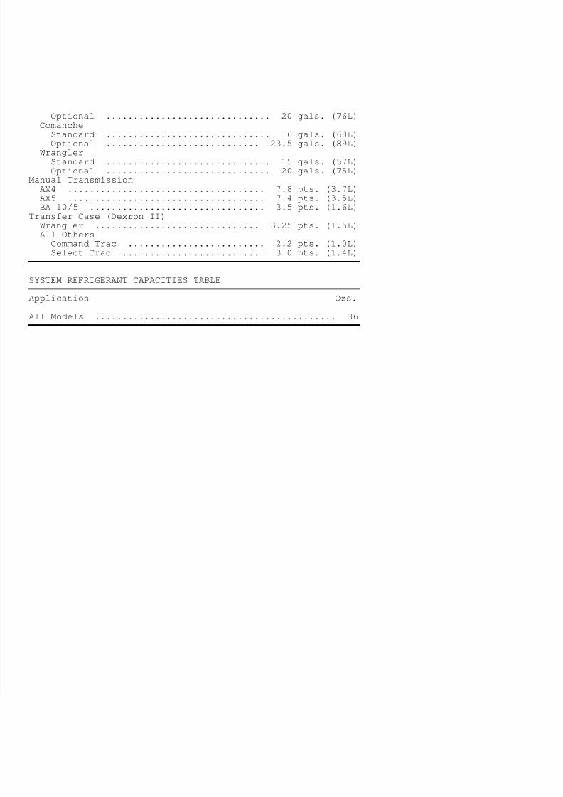
7/30/2019 22301937-Tuneup-6-Cyl
http://slidepdf.com/reader/full/22301937-tuneup-6-cyl 13/13
Optional .............................. 20 gals. (76L)Comanche
Standard .............................. 16 gals. (60L)Optional ............................ 23.5 gals. (89L)
WranglerStandard .............................. 15 gals. (57L)Optional .............................. 20 gals. (75L)
Manual TransmissionAX4 .................................... 7.8 pts. (3.7L)AX5 .................................... 7.4 pts. (3.5L)BA 10/5 ................................ 3.5 pts. (1.6L)
Transfer Case (Dexron II)Wrangler .............................. 3.25 pts. (1.5L)All Others
Command Trac ......................... 2.2 pts. (1.0L)Select Trac .......................... 3.0 pts. (1.4L)
¡ ¡ ¡ ¡ ¡ ¡ ¡ ¡ ¡ ¡ ¡ ¡ ¡ ¡ ¡ ¡ ¡ ¡ ¡ ¡ ¡ ¡ ¡ ¡ ¡ ¡ ¡ ¡ ¡ ¡
SYSTEM REFRIGERANT CAPACITIES TABLE¡ ¡ ¡ ¡ ¡ ¡ ¡ ¡ ¡ ¡ ¡ ¡ ¡ ¡ ¡ ¡ ¡ ¡ ¡ ¡ ¡ ¡ ¡ ¡ ¡ ¡ ¡ ¡ ¡ ¡
Application Ozs.
All Models ............................................ 36¡ ¡ ¡ ¡ ¡ ¡ ¡ ¡ ¡ ¡ ¡ ¡ ¡ ¡ ¡ ¡ ¡ ¡ ¡ ¡ ¡ ¡ ¡ ¡ ¡ ¡ ¡ ¡ ¡ ¡
![celerkat1.3 volvo1 Pub98[1] · 4-cyl DKS 4-Cyl Seiko-Seiki 4-Cyl DKS pad 6-Cyl SD-709 6-Cyl SD7H15 #7828 6-Cyl SD7H15 #7846/7930 6-Cyl SD7H15 #7935 Kondensorer/Condenser 1991 92-93](https://img.pdfslide.net/doc/110x75/5f3a997e71773a6bab1b0fa3/celerkat13-volvo1-pub981-4-cyl-dks-4-cyl-seiko-seiki-4-cyl-dks-pad-6-cyl-sd-709.jpg)