Embed Size (px)
Citation preview
••
•
Report Nos.
Docket Nos.
License Nos.
Licensee:
U. S. NUCLEAR REGULATORY COMMISSION
REGION I
50-272/88-08 50-311/88-08
50-272 50-311
DPR-70 DPR-75
050272-880211· 050272-880218 050272-880224
050311-880208 050311-880213
Public Service Electric and Gas Company
P. 0. Box 236
Hancocks Bridge, New Jersey 08038
Facility Name:. Salem Nuclear Generating Station - Units 1 and 2
Inspection At: Hancocks Bridge, New Jersey
Inspection Conducted: February 16, 1988 - March 21, 1988 ·
:::~::::r:~: 4~ctor ~Sw~nd, Chief, Reactor Projects Section No. 28, Projects Branch No. 2, DRP
Inspection Summary:
34s-~~g~ ·date
Inspections on February 16, 1988 - March 21, 1988 (Combined Report Numbers 50-272/88-08 and 50-311/88-08)
Areas Inspected: Routine inspections of plant operations including: operational safety verification, maintenance, surveillance, review of special reports, 1 icensee event followup, storage battery adequacy audit (temporary instruction 87-07), and assurance of quality. The inspection involved 105 inspector hours by the resident NRC inspector.
Results: This report documents a Unit trip on Unit l during physics testing and the apparent failure of a reactor trip breaker on Unit 2. The report also documents the results of a battery adequacy audit. Two ·licensee identified violations were noted in Section 6 involving not staggering surveillance tests for redundant components, and missed grab samples for steam generator blowdown discharges.
890~17021~ 880325 F'Uf·< ADOU: .. 05000272 Q PDC

• 1.
DETAILS
Persons Contacted
Within this report period, interviews and discussions were conducted with members of 1 icensee management and staf.f as necessary to support inspection activity.
2~ Operational Safety Verification (71707, 71709, 71710 and.71881)
2.1 Documents Reviewed
Selected Operators( Logs Senior Shift Supervisor's (SSS) Log .Jumper Log Radioactive Waste Release Permits (liquid & gaseous) Selected Radiation Work Permits (RWP) Selected Chemistry Logs Selected Tagouts Health Physics Watch Log
2:2 The inspector conducted routine entries into the protected areas of the plants, including the control rooms, Auxiliary Building, fuel buildings, and containments (when access is possible). During the inspection activities, discussions were held with operators, technicians (HP & I&C), mechani~s, security personnel, supervisors, and plant management. The inspections were conducted in· a'ccordance with NRt Inspection Procedures 71707, 71709, 71710, and 71881 and affirmed the licensee's commitments and compliance with 10 CFR, Technical Specifications, License Conditions, and Administrative Procedures.
No violations were identified.
2.2.1 Engineered Safety Feature (ESF) System Walkdown: (71710)
The inspectors verified the operabi 1-i ty of the se 1 ected ESF system by performing a walkdown of accessible portions of the system to confirm tha{ system l~neup ~rocedures match plant drawings and the as-built configuration. This ESF system walkdown was also conducted to identify equipment conditions that might degrade performance, to determine that instrumentatio~ is calibrated and functioning, and to verify that valves are properly positioned and locked as appropriate. The Intermediate Head -Safety Injection System (Unit" 2) and Auxiliary
· Feedwater System (Unit 1) were inspected. No deficiencies were identified.
- :.- . . -·:
'.,-
•.
•
•
•
3
2.3 Inspector Comments/Findings:
The inspector selected phases of the units' operation to determine co~pliance with the NRC 1 s regulations. The ihspector determiried that the areas inspected and the licensee's actions dfd noi constitute a health and safety hazard to the public or plant personnel. The following are noteworthy areas the inspector researched in depth:
2. 3 .1 . Unit 1
The refueling outage was completed and on February 2; - . 1988, the unit was brought critical to conduct low power physics testing.
On February 19, 1988, the licensee· identified a lower than normal megger reading (resistance to ground_) on rod drive mechanism 1SA2 (a rod in Shutdown Bank A). The rod was operable and the licensee decided to proceed with physics testing in order to complete the outage. It was anticipated that the rod drive mechanism would be replaced at a later date.
On February 24, 1988, at 4:36 a.m., the reactor tripped from 2% power due to a high flux trip on channel N35 (intermediate range). The trip signal was caused when an instrument technician failed to follow a procedure and pulled the fuses on that channel before placing the trip channel in bypass.
The technician had been working on channel N35 prior to · the trip and spikes were seen on the average reactor coolant temperature reference signal in the control room. The Shif~ Supervisor directed the technician to· investigate the relationship between the work being perfbrmed on channel N35, and the Taye deflections.· The technician failed to follow the procedure to plac~ the trip channel .in bypass prior to removal of the fuse. Subsequent investigation produced the following facts:
The experienc~d technician was preoccupied with th~ Tave interference with channel N35 and was trying to figure out the connection. He admitted to having the procedure but not returning to the correct step in the procedure, "Place the channel in bypass" and proceeded to remove the instrument fuses thus causing the trip .
·' ,··,
. . ' . ~ :-, ·-.
:·-.
. · ... '_
•
•
2.3.2
•
4
The licensee is committed to the INPO Human Performance Evaluation System (HPES) to investigate plant occurrences. ·This was the first case to be evaluated and will be reviewed by the resident inspector when availabJe.
The spikes in the Tave program were subsequently attributed to a faulty RTD in No. 13 hot leg. The RTD's, which were installed during the outage have two elements (primary and secondary). The primary was found deficient and the secondary was connected in its place. The system has functioned normally since the change was made.
Thi~ item remains unresol~ed pending completion of these actions and NRC review of the Licensee Event Report. (UNR 272/88-08-01)
During the shutdown, rod drive mechanism 1SA2 was replaced.
The unit was taken critical on February 26, 1988, and returned to service on February 28, 1988 following the completion of low power phy~ics testing.
On February 29, 1988, a primary to secondary leak was discovered in the No. 13 steam generator: Power ascension was stopped and power was stablized at 80%. With steady state conditions, the: leak rate was calculated to be between 40 and 50 gallons per day (gpd). The unit resumed power ascension to full power at a rate of 1% per hour with close monitoring of the leak rate. The leak rate stabilized at 150 gpd at 100% power with the licensee sampling the blowdown on a two hour basis. As of March 21, the leak rate has decreased to 25-50 gpd. Blowdown and air ejector monitors have remained constant throughout this period. The licensee is continuing to sample the steam generator and evaluate the results. Procedures are in place to define a course of action should the leak propagate.
At the end of this report period the unit was at 100% power.
Unit 2
The unit began this report period at 100% power and continued operation at full power throughout the period. At 11:25 a.m. on February 17, 1988, the licensee made a one hour notification to the NRC, stating that 11 811 reactor trip breaker did not open within 10 cycles during the performance of a monthly surveillance. The undervoltage trip attachment would have opened the breaker in 83 cycles, but the shunt attachment opened the breaker in 2 cycles. The breaker
• 2.3.3
5
was replaced with 11 A11 bypass reactor trip break.er which had tested satisfactorily. The licensee then declared 11 811
reactor trip break.er operable at 12:47 p .. m. on February 17, 1988. Subsequent investigation by the licensee, as observed by the resident inspector, indicated that the breaker functioned properly, but the computer time sequencer may have
·printed an erroneous reading on the sequence of events recorder. The licensee performed the following:
M3Q3 Maintenance Procedure to test DB-50 Westinghouse breakers. The test was performed three times and the results were the same as the 11 as left" condition of the break.er recorded from the previous test, which had b~en pe~formed one month earli~r.
Tests to try and duplicate the sequence of events from -~ the computer were unsuccessful, however, the licensee removed the card, cleaned and tightened the connectors,. and replaced and tested the card.
All tests were inconclusive a~ to why the computer or break.er had failed the test so the licensee replaced the undervoltage trip device and retested the breaker.
Both Units
On February 16, 1988, Mr. Steven E. Milteriberger relieved· Mr. Corbin A. McNeill ·as Chief Nuclear Officer. Mr. Miltenberger will assume the title of Vice President and Chief Nuclear Officer and will report to PSE&G chief executive officer, Mr. James Ferland, on nuclear operation matters. Mr. McNeill has taken a position with the Philadelphia Electric Company.
No violations were identified.
3. Maintenance Observations (62703)
The inspector reviewed the following safety related maintenance activities to verify that repairs were made in accordance with approved procedures and in compliance with NRC regulations and recognized codes and standards. The inspector also verified that tne replacement parts and Quality Controls utilized on the repairs were in compliance with the licensee 1 s QA program.
4.
Unit 1
Work Order N0mber
880108061
Unit 2
Work Order Number
880217714
6
Maintenance Procedure
lPD-14.1.003 Removal and Replacement of necessary equipment from the reactor vessel head to replace 1SA2 Magnetic Jack.
lPD-8.2.001 Electron~c check (megger) of newly installed Magnetic Jack.
ICl.4.003 Rod Testing and IRPI Checks.
M~intenance Procedure
M3Q-2 Reactor Trip Breaker Lubrication and Testing All-1 Calibration Verification of the Shore Stake tool (crimping tool).
Descri p_t ion
Replacement of Magnetic Jack for rod 1SA2.
Description
Replacement of the undervoltage coil and retesting of reactor trip breaker 11 811 SN 02YN219-6.
No violations were identified.
Surveillance Observations (61726)
During this inspection period, the inspector reviewed in-progress surveillance testing as well as completed surveillance packages. The inspector. verified that the surveillances were performed irt accordance with licensee approved procedures and NRC regulations. The inspector also verified that the instruments used were within calibration tolerances and that qualified technicians performed the surveillances.
The following surveillances were reviewed:
Unit 1
SP(0)4.7.6.la Control Room Ventilation - Tests and verifies the Emergency Control Room Area Air Conditioning System in accordance with (IAW) Technical ·specification 4.7.6.la.
- .
•
•
SP(0)4.8. l. l. lb
SP(0)4.8.2.3.1
Unit 2
SP(0)4.0.5-P-RH (21)
SP(0)4.3.3.7
7
Bus Transfer - Tests the operability of the bus transfer device from the vital bus source to .the alternate source, IAW Technical Specification 4.8.1.1.lb.
DC Breaker Alignment - Verifies the three DC busses' breaker alignment, !AW Technical Specification 4.8.2.3.l.
Tests the operability of No. 21 Residual Heat Removal Pump, IAW Technical Specification 4.0.5.
Post Accident Monitoring - Tests and verifies post accident monitoring instrumentation operable, !AW Technical Specification 4.3.3.7.
No violations were identified.
5. Review of Periodic and Special Reports (90713)
Upon receipt, the inspector reviewed periodic and special reports. The review included the following: inclusion of information required by the NRC; test results and/or supporting information consistent with design predictions and p~rformanc~ specifications; planned corrective action for resolution of problems, and reportability and validity of report information. The following periodic reports were reviewed:
Unit 1 Monthly Operating Report - February, 1988
Unit 2 Monthly Operating Report - February, 1988
Special Report 88-02, Unit 2. This report documents the licensee's a·ctions connected with the 11 811 reactor trip breaker. This incident is disc~sied in Section 2 of this report. The inspector has no further questions at this time.
No violations were identified.
6. Licensee Event Report Followup (90712)
The inspector reviewed the following LER's to determine that reportability requirements were fulfilled, immediate corrective action was taken, and corrective action to prevent recurrence had been accomplished in accordance with Technical Specifications.
. :~::
• Unit 1
88-001-00 Diesel Generator Day Tanks Do Not Meet Seismic Criteria
This LER discusses th_e discovery and repafr of improperly welded -diesel generator day tanks. During a system wilkdown for the
,.-
preparation of a Probabilistic Risk Assessment (PRA), it was discovered -~ that the structural welds that attached the day tank to the base were not properly made. The welds were not long enough to satisfy the seismic criteria. The welds were subsequently repaired and are now in compliance with the seismic criteria. The licensee is in the process of :identifyihg how the discrepancy occurred. Unit 2 tanks were checked, and they were within specifications. The inspector has no f~rther questions at this time._ -
88-002-00 Tavg Deviation on All Channels Due to Design
This LER discusses the discovery and repair of a manufacturer's design modification of a component used with RTDs recently installed for measuring reactor coolant temperature. When the RTDs were placed in service, a 5 degree F deviation was noted which caused the licensee to enter technical specification action statement 3.0.3 (motherhood) for forty minutes. The subsequent investigation revealed the following:·
All of the RTDs utilized a low level amp which compensates for signal loss due to hundreds of feet of cable iosses.
The low level amp had a-pre-installed jumper across the temperature compensation circuit. This circuit was not identified to the licensee.
The 5 degrees F difference in readings between wide range and narrow range reactor coolant temperature did not become evident until temperature went above 530 degree~ F which is the beginnin~ of the narrow rang~ reading.
All RTDs had been replaced during the refueling outage, and all tracked together.
Testing prior to heatup was done with the RTD and compensator disconnected. This is a normal practice.
The licensee removed the jumper in the -low level amp, and the component responded properly and tracked with narrow range temperature.
The licensee has corresponded with the Manufacturer, informed other utilities through INPO 11 note-pad 11
, modified the.design prior to ~nstallation into Unit 2, informed maintenance personnel and updated their ordering system for replacement parts.
•
••
9
The inspector has no further questi.ons.
88-003-00 Reactor Trip on a False Intermediate Range - High Flux Si gna 1 Due to Personne 1 1Error
This LER event is discussed in Settion 2 of this report. The inspector has no further questions.
Unit 2
88-003-00 Technical Specification (TS) Table 3.3-12 Action 27 Not Complied With Due To Personnel Error
This LtR discusses missed periodic samples of the radiation monitoring system (Blowdown From 11 C11 Steam Generator) as required by an action statement.' The cause was identified as a commtinication and training problem between an instrument technician and the shift supervisor. The technician had discovered, while working on the high pressure regulator in the system, that the low pressure regulator was also inoperable. He failed to communicate this properly to th~ shift supervisor and did not inform his imm~diate supervisor. As a result, the system was returned to service without the lbw pressure regulator in service, thus there was no flow through the detector. This is not evident in the control room area and the system appeared normal. During -the period with no samples, downstream detectors in the main blowdown header did not detect any radioactivity. The licensee has conducted 11 workshop 11 type training sessions with I&C technicians to discuss the event and operations management has ~eviewed the event with shift supervisors. The licensee is also investigating the need to change applicable procedures to prevent recurrence of the event. The inspector determined that this event represents a licensee ide~tified violation of TS 3.3-12, for which no further action is required. (NV4 311/88-08-02)
88-004-00 Technical Specification Surveillance 4.3.2.1.1 Not Performed on a Staggered Basis~ Inade~uate Administrative Control
This LER discusses the lack of staggering of testing of relays within the safeguards equipment cabinet as per technical specifications. Technical specifications require staggering to minimize the probability of multiple failure during accident conditions. The licensee performed the tests on both A and B trains and did not stagger the testing. The root cause has.been identified in the computer system that is to date -incapable of scheduling staggered surveillances. The licensee has identified other syst~ms that require staggering and will address them manually. The licensee is also investigating the feasibility of changing the computer program to accommodate the required scheduling .. The i.nspector determined. that this event represents a licensee identified violation of TS 4.j.2.1(1), for which no further action is required. (NV4 311/88~08-03)
•
•
10
7. Region I Temporary Instruction 87-07, Storage Battery Adequacy Audit (71707)
This instruction was issued to gather information on storage batteries. The following are the questions asked the licensee and their responses. The following format lists the questions as a group, followed by the licensee's response.
A. General Battery Information
Document the below information for batteries which carry vital loads.
( 1)
(2)
(3)
(4)
(5)
A. l
A.2
Qualified, or design, seismic life
Qualified, or design, electrical life
Age
Time in service
Plans for replacement
''Nuclear Environmental Qualifications Report QR-2-27504 11
dated June 1984 describes the method used for the qualification of Salem's batteries and battery racks. (See Attachment 1).
The qualification of the battery's electrical life is described in the same re~ort mentioned in A.(l). Qualified and design electrical life is based on previous natural and accelerated aging tests conducted on type L. e. cells of identical and similar material and design. All accelerated (thermal) aging was conducted at a controlled test chamber temperature of 160 degrees F ± 2 degrees F. The test cells were float charged during the accelerated aging proces~. The qualified electrical and seismic life is more than 20 years based on this report.
A.3 The age of the oldest cells contained withi~ each of the class IE batteries is as follows:
lA 22 voe 17 years lB 22 voe 17 years
lA 125 voe 3 months lB 125 voe 1 month le 125 voe 4 years
••
2A 28.VDe 2B 28 voe
2A 125 voe 2B 125 voe 2e 125 voe
11
16 years 16 years·
17 years 16 years 3 years
A.4 Although the time in service is less than the actual age of the batteries, the licensee assumes the two to be the same since this gives a conservative _estimate of battery service time.
A.5 As can be seen in answer 1-3; 4 batteries have already been replaced within the last 4 years. The rernairiing batteries will be replaced within the n~xt 2 refueling outages for each unit. ·
B. Previous Licensee Actions
Identify actions taken on the following IE Information Notices: 83-11, Possible Seismic Vulnerability of Old Lead Storage Batteries; 84-83, Various Battery Problems; 85-74, Station Battery Problems; and 86-37, Degradation of Station Batteries.
B.l Attachment 4 contains PSE&G 1 s responses to these IE Notices.
e. Seismic Lifetime and Qualification
For batteries supplying vital loads, identify the following information.
(1) Licensee and/or manufacturer 1 s establishment of seismic lifetime. This maybe through documentation allowing verification by competent personnel other than the qualifiers and containing design specifications, the qualification m~thod, results, a~d justifications (ref: IEEE 535-1986)~
(2) Seismic qualification maintenance. Identify how the criteria for assuring that the battery and rack will maintain seismic qualification are defined, available, and used for periodic inspections and cell replacements. Identify the criteria for determination of seismi~ end of life based upon the inservice condition of the battery.
e.1 Wyle Test Report No. 46661~1 for Le-33 (see Attachment 1) cells seismic qualification test indicates that these batteries, after. being subjected to a multi-frequency qualification test (5 O.B.E, prior to one 0.8.E), has proven that their rated capacity was well above 80~ throughout the test program .
12
C.2 Seismic qualification documentation plus visual inspection of the battery cells on a weekly and quarterly basis provides adequate assurance that the battery cells are· seismically qualified. Also, if visual examinatibn bf.the rack shows no signs of deterioration due to corrosion and if all nuts, bolts, clamps and miscellaneous hardware are tight, the battery rack is assumed acceptable based on the.original seismic qualification report. If visual damage of the battery rack or battery is found, either a replacement of the damaged component wo~ld occur or a safety evaluation by a qualified engineer would be necessary for continued use. See Attachment 2 fof a safety evaluation example.
D. - Electrical Sizing and Qualification
For batteries supplying vital loads, identify the following inf6r~ation.
(1) Confirmation that the battery size is sufficient to handle the load profile with a suitable margin.
(2) The means of tracking and control of battery loads such that the batteries and their replacements will have sufficient capacity throughout design life. This should assume that worst case electrolyte temperature and other worst case conditions exist when the battery is called upon to perform its design function.
(3) The ~revisions for consideration·of the effect of jumpered out cells upon the ability of a battery to perform under
. worst case conditions.
D.1 Preliminary calculations have been completed by the Engineering and Plant Betterment Department. Final calculations by Ebasco are in progress.
D.2 Presently there isn't any formal method of tracking and controlling battery ioads, other than the design change process which would require any changes to be compared with current specifications to en~ure that the design loading is not
_exceeded. A computerized DC bus load monitoring system, where l-0ads and margins will be available on demand, is presently being developed.
D.3 Engineering Safety Evaluation S-2-E200-NSE-221, (Attachment 3) indicates that the No. 28 125V DC battery will operate as required with cell No. 36 jumpered out. (%capacity for battery with cell No. 36 out of service is 101%). The final Ebasco battery capacity calculation mentioned in 0.(1) will also address this issue.

•
13
E. Battery Ventilation and Protection From Ignition Hazards
For batteries carrying vital loads, identify the following. - -
(1) The provisions for assuring adequacy battery ventilation during normal operation, outages, charging, and dischbrge.
(2) Adequacy of checks of battery ventilation flow.
(3) Adequacy of controls over battery ventilation impediments such_ as enclosing the battery space or its ventilation with plastic sheeting, or any other ventilation obstructions, duri~g outages and other periods.
(4) -Adequacy of hydrogen detection equipment and its calibration and use, or of the technical justification for not .using such equipment.
(5) Knowledge of the hydrogen hazard on the part of plant management, operating shift management, and personnel who access the_ battery spaces.
(6) , Prohibition of hot work and smoking in battery spaces, including checking the spaces for the residue of such activity.
(7) Assurance that battery cells are secured, with ~ost-to-case and top-to-jar seals tight. Thefmometers should not be left in cells after temperatures are measured. - Caps on the filler openings should be properly secured when not required to be off. (Cells.should be vented only through the flash arrestors.)
(8) The means bf assuring proper elimination of water-carrying pipes (e.g., HVAC lines) from battery spaces, especially those which may carry salt water.
(9) The means of positive control over the quality of water added to the batteries to assure that the manufacturer's _recommendations or an appropriate licensee standard are met or exceeded. -
(10) The assurance of elimination of combustibles, and loose equipment and conductors, from· battery spaces.
E.1 The following calculations demonstrate the size of the fan required in each battery room in order to prevent 1% of hydr6gen (H2) accumulation during the following conditions:
·: ;·:
·:··"
-~,
.. -...,
I
I
•
14
a. Charging the battery b. Normal operation c Discharging the battery
Maximum release of H2 per cell Maximum release of H2 per hour
per per
hour= 0.0112 CF 60 cells= 0.0112 C.F.H x
60 Maximum release of H2 per hour per 60 cells - .672 C.F.H of
H2 Amount of fresh air needed X = .672 C.F.H = 67.2 C.F.H
.01 In minutes X = 67.2 C.F.H = 1;12 C.F.M OF
60 fresh air
E.2 All battery testing and maintenance procedures instruct personnel to periodically check exhaust fan operation while working on batteries.
E.3 As part of the license requaiification training, licensed operators are instructed on the -importance of battery room ventilation. In addition, the operators log the operation of the battery room exha~st fan~ on a daily basis.
Maintehanc~ personnel are guided by maintenance procedures which mention the importance of maintaining battery room ventilation ..
All other personnel that may be exp6sed to storage batteries are given the opportunity to use the Nuclear Depart~ent Safety Manual which has a section on safety considerations when dealing with storage batteries:
E.4 Existing plant procedures do not call for the use of hydrogen detection equipment. Existing procedures call for maintaining ventilation equipment in an operable condition to guard against hydrogen gas buildup.
One fan wiih a 400 CFM displac~ment ca~a~ity is installed in 3 of the battery rooms. A fan with a 250 CFM di s'p l atement is installed in the fourth battery room. The calculations i~ E.(1) indicate that the installed battery room fans with a 400/250 CFM capacity displacement are more than adequate to ventilate the rooms. Therefore, hydrogen detection capability is not necessary.
E.5 ·As previously discussed in Item E.(3), ·plant personnel who work with the batteries are given the necessary training .to ensure that they are aware of the importance of proper ventilation to eliminate the possibility of explosion from a hydrogen buildup concurrent with a spark .
.. " .,.
15
E.6 There are red warning signs in each of the battery rooms prohibiting sparks or open flames. The battery maintenance procedures warn against smok1ng/sparks in the battery area and also require _a check for cleanlin~ss, and cleaning if necessary.
When hot work is to be performed in the battery room, only qualified personnel are allowed to conduct this type of work with the ventilation fan in operation.
E.7 The battery maintenance procedures require visual ins¢ection of all battery cells for cracked or leaking jars, and any signs of electrolyte wetting at the battery post· seal.
E.8 Inspection of the class IE battery spaces has indicated that there are no water carrying pipes in any of these areas. An adjacent room for the non-class IE 250 VDC battery has an eyewash station which has a water supply line.
E.9 When water is required to be added to the battery cells to maintain the proper level, it is taken from the station demineralized water system. Attachment 5 shows the Salem Station Water Quality St~ndard for demineralized water and the frequency of sampling to ensure these standards are met. Power System Inc. (battery manufacturer) will be contacted to make sure these standards meet or exceed the manufacturers• requirements.
E.10 All battery maintenance procedures call for the elimination of non-essential materials and cleaning of the battery area when required. The most frequently performed procedure is M3M which is done on a weekly basis.
F. Electrolyte Temperature Control
For batteries supplying vital loads, identify.the adequacy of the ·following.
(1) Avoidance of localized heat sources such as direct sunlight, radiators, steam pipes, and space heaters.
(2) That the location/arrangement provides for ·no more than a 5 ·degree F difference in cell temperaturer as confirmed by measurements representative of operating conditions. If this is not the case, then the licensee and manufacturer should have identif~~d the consequent impact on expected battery and individual cell capacity and life, and surveillance procedures. should reflect the additional allowable .temperature variation.
••
•
16
F.1 None of the Class IE battery space~ have contact with localized heat sources such as direct sunlight, radiators, steam pipes and space heaters.
F.2 The service and capacity test maintenance procedures have demonstrated that individual cells do not experiente gre~ter than 5 degrees F difference/cell during float operation prior to discharge.
G. Charging
For batteries carrying vital loads, identify the adequacy of the following.
(1) Provi~ion for a freshening charge after more than 3 months of being on open circuit, unless determined by the manufacturer to be unnecessary to assure rated capacity throughout life.
(2)
(3)
(4)
(5)
Accomplishment of equalizing charges at 18 month intervals, .and when the corrected specified gravity (SG) of an individual cell is more than 10 points (0.010) below the average of all the cells, and when the average corrected SG of all cells drop more than 10 points below the average
·installation value, and if any cell voltage. is belo~ 2.13V. (Specific manufacturer 1 s provisions and assessment may allow the non-performance of some of these recommended charges, or may provide differ~nt criteria.)
Control over battery water quality such that specified purity is confirmed before addition, that water added just prior to charging is added only to bring the electrolyte up to th~ prescribed minimum (to prevent overflow during charging), and that water· added after and between charges does not bring the level above the prescribed maximum (unless manufacturer 1 s instructions provide for other water addition measures).
That routine float and final end of charge SGs not be taken before 72 hours of float operation after completfon of the charge and the last water addition, unless the manLlfacturer 1 s instructions provided otherwise. (The need is for measurement pf ~epresentative cell level~ and average them).
Establishment and maintenance of float voltage in accordance with the man~factur~r 1 s instructions .
• 17
(6) Assurance that single-cell charger use does not violate Class lE independence from non-class lE equipment.
G.l The battery manufacturers' recommendat~ons are followed for maintaining a cell which has been shipped to the -site but has not yet been put in service. An rifficial station procedure to govern this activity does not presently exist and the licensee recognizes this to be a deficiency that requires correction. ·
G.2 An equalizing charge is performed at least every eighteen months as part of .the battery service or capacity tests. -An equalizing charge could be performed on a more frequent basis if required. All battery cells are monitored on a, quarterly basis for determining cell voltages per technical specifications are at least 2.13 V per cell under float charge with no cell less than .27 volts below the original acceptance test. Also, the specific gravity corrected to 77 degrees F and full electrolyte level, is verified not to be less than 1.200 and shall not have decreased by more than .02 from previous reading as required by technical specifications.
G.3 The battery service and capacity test maintenance procedures provide guidance for the addition of demineralized water to 'cells. Cell level adjustment is made 24 to 72 hours after equalize charging to replace electrolyte lost during recharge and to help precJude the chance of overflow during the equalize charging.
G.4 The existing battery service test procedures require 24 to 72 hours ~f float charge before taking SG 1 s and ICV 1 s while our exist~ng capacity service test procedures requires 72 hours before taking SGs and ICVs, The licensee currently has developed a draft procedure for the battery service test which will require 72 hours of float charge before taking SGs and IVes.
G.5 The battery maintenance procedures list the nominal float voltage per cell to be 2.20 voe to 2.25 voe.
G.6 The existing single cell battery charge maintenance procedure does· not give specific instructions regarding channel separation. This subject will be further reviewed so that the appropriate action can be taken.
H. Performance Tests and Replacement Criteria
For batteries carrying vital loads, identify the following.
(1) Initial accepiance testing which demonstrates the ability of the batteries to meet the manufacturer 1 s rating.
l I
- .. : .
•
•
18
(2) Service testing which demonstrates the ability to carry the load profile with an appropriate margin for worst case conditions, including end of life loss of capacity under the worst case electrolyte temperature.
(3) Accomplishment of a performance test (capacity test discharge) within the first two years of service and at 5 year intervals until signs of degradation are evident or 85% of the qualified service life is reached.
(4) Annual performance testing of batteries which show signs o-f degradation or which have reached 85% of the qualified service life ts reached.
(5) Ena of electrical lif~ criteria which consider the rapid end of life drop-off in capacity, worst case state of charge during float service, worst case electrolyte temperature, current DC loads, and the time needed to replace the battery while it can still handle worst case conditions.
H.l All class IE battery acceptance tests have shown 100% or great~r capacity.
H.2 The existing service testing of station batteries is in the midst of being upgraded although the existing service test demonstrates the battery to be capable of performing its required function. Technical specification changes may be required to support the ~ervice test r~vision.
H.3 The battery capacity maintenance procedure M3A did not address acceptance testing although records indicate acceptance testing has been done in the past. Tests are directed to be done every 60 month~ until capa~ity is less than .90% at which time the ~ystem ~ngineer should be notified so that the appropriate action can be taken. If capacity is less than 85%, the senior shift operator as well as the system engineer are notified. Maintenance procedure M3A will be revised to include the requirement for acceptance testing.
H.4 Since the system engineer by procedure has been notified when battery capacity has reached 90%, he woul~ consult IEEE Standard 450 for other information. IEEE 450 states that perfofmance testing should be increased to once a year for a battery with 85% capacity. Therefore, it is reasonable to assume that this approach would be taken unless the vendor recommended otherwise .
, ... <- ·:. ... ~ . ' . ·,
•• 19
H.5 An initial study was recently completed by the Engineering and Plant Betterment Department (E&PB) on battery·capacity b_ased on aging degradation and temperature correction. It was determined that adequate capacity existed on class IE systems. A more det'ailed study is curr·ently underway.-.
I. Other Safety-Significant Wet Cell Batteries
For safety-significant wet cell batteries not used for vital loads, show how the ,maintenance program periodically determines the ability to perform the design function and provides for ti~ely replacement of batteri~s and for maintaining associated equipment (e.g., chargers).
I.l Other safety significant batteries such as the bne used for the security_ system are currently being studied by E&PB.
8. Assurance of Quality ,
During this inspection period assurance of quality was ~videnced-by the Quality Assurance inspectors that witnessed the installation of the new control r6d drive mechanism (1SA2) and the testing and refurbishment of 11 B11 reactor trip breaker. ·Both maintenance evolutions were completed properly the first time and tested by the procedure successfully. Quality assurance was also evident in the .licensee•~ responsible approach and reporting of primary to seco·ndary leakage (identified in Section 2 of this report). The leak was reported promptly and monitored in accordance with procedures. A clear and concise record has been kept for ins~ector audits.
Some personnel errors have been identified within this report and this areas continues to be an area of concern. However, the licensee has acted on correcting the communications and personnel error problems by first instituting the INPO Human Performance Evaluation System which will identify what the licensee can do to further reduce the aforementioned problems; and second, by conducting counseling and enhancing training in the personnel and communication~ areas.
9. Unresolved Items
Unresolved items are matters about which more information is required in order to ascertain whether they are acceptable, deviations or violations. Unresolv~d items are discussed in section 6 of this report.
'10. Exit Interview (30703)
At periodic intervals during the course of the inspection, meetings were held with senior facility management to discuss the inspection scope and findings. An .exit interview was held with licensee management at the end of the reporting period. The licensee did not identify 2.790 material.
.-
---···. IALLIE··· -0. -~ir~cHMENT 1 (NUCLEAR ENVIRONMENTAL o..uAuncAnoN · RE:P_ORTJ
~ Power System~
-~:;.c:·;, vva·~=~·~::-a:: ·.,-·- __ ,:_ P1yr-.c ... :~ ~ee:.~; =.:. ·;.:.:;. Te1epr-io.-.e ~ • ~ S~:-;-::·: r.eietyoe 5 • ~·f:€C·:.s ::e
(
• 1.0
2.0
, .• o
4.0.
I 5.0
• 6.0
1.0
8.0
•
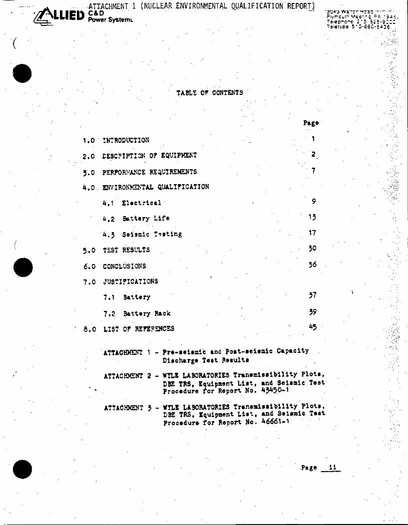
TABLE O!' CONTENTS ..
!~":'RODUCTION
tESC?IPTION OP' EQUIPMENT
PERF'OR.VJ.NCE REQUIREMENTS ·
ENVIRONYZNTAL Q~LIP'ICATION
4., Elect.!"ica.l ·
~.2 Battery Life
4,, Seismic '!'"!lting
TEST RESULTS
CONCLUSIONS
JUSTI!"ICATIONS
7., Battery
7.2 Battery Rack
LIST OF RE1!F::NCES
Page·
1
2
·7
9 ,, 17
,o ,6
ATTACHMENT 1 - Pre-1ei1mic and Po1t-1ei1.m1c Capacity Di1oh&rge Teat ~e1ult1
ATTACHMENT 2 - WTLI LABORATORIES Tran1mi11ibil1 ty Plot.1, DBE TRS, Equipment Lilt, and Sei1mic· Test. Procedure tor Report No. 4'450-1
ATTACHMENT 3 - WTLI LABORATORIES Tr1.n1m111ibility Plott, DBE TRS, Equipment Li•~. and Sei1mic Teat Procedure for Report. No~ 46661-1
Page _!..!._
""···
\ .
·'. '.
·~ .·
• •
'
1. 0
M1£$$§Jl£Ri$iA )»C:&~a;mzw_ a EE
INTRODUCTION
This report presents the Nuclear tnvironmental
Qualification of C & D POWER SYSTEMS LC-33
stationary battery and two step battery rack for
the Salem Nuclear Generating Station.
Qualifi~ation is provided in accordance with Public
Service Electric & Gas Co. P.O. No. 923023 and
932407 requirements as well as the guidelines set
forth in IEEE Standards 323-1974, 344-1975 and
535-1979.
The basis .for qualification is a review and analysis
of previous test data; including the results from
thermal and natural aging, seismic test ·and analysis,)
and battery capacity tests.
Pa~ __ 1 __
•- raqcs awaasa rutUJCLS ESE WZWSICC&i=&ED.t& S&SJJ I XS
-·~-· .
:'··
- ... :o
· .. -'.
• •
• •
• •
4LLIEI> ~rSystems
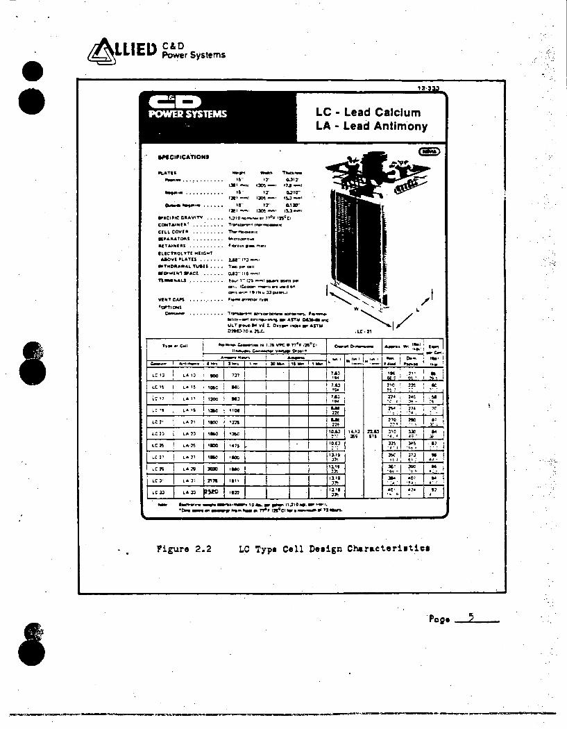
2.0 DESCRIPTION OF EQUIPMENT
The equipment qualified by this report is the
125 volt de LC-33 batte~y and two step battery·
racks for the Salem Nuclear Power Station.
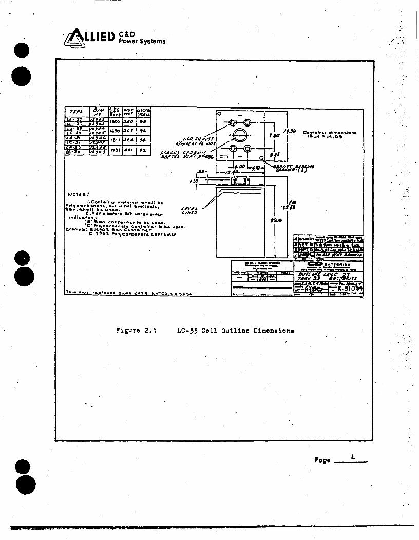
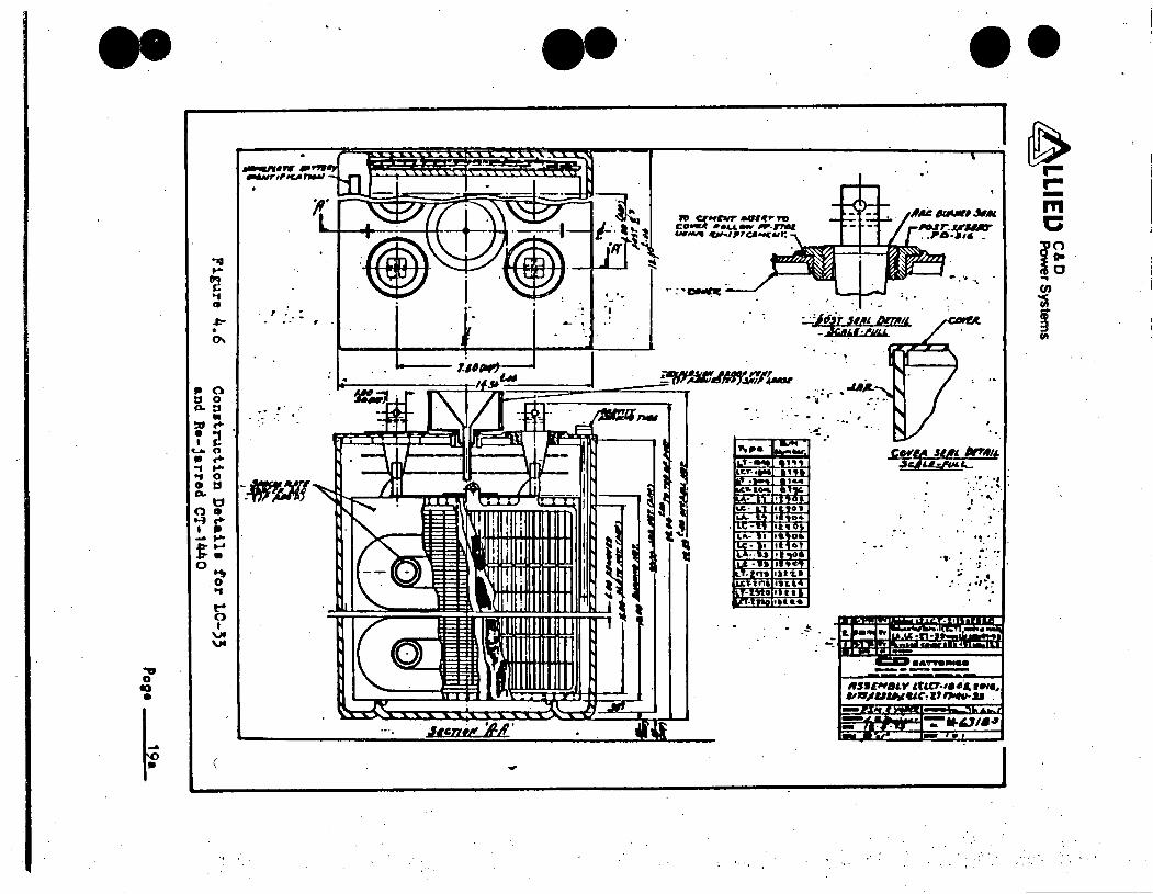
2.1 ·The LC-33 battery cell consists of pasted
plates wiih lead calcium alloy grids· encased
in a vented container. Sixty individual two
volt cells, series connected· with bolted conn
ectors, comprise the 125 volt battery. The
electrolyte is a sulfuric acid and water
solution with a nomin~l fully charged specific
gravity of 1.210 + .010 at 77°F. The LC-33
battery cell is iu~ther described in C & D
BATTERIES Drawing No. K-5103 and Section 12-333
which appear in Figures 2.1 and 2.2.
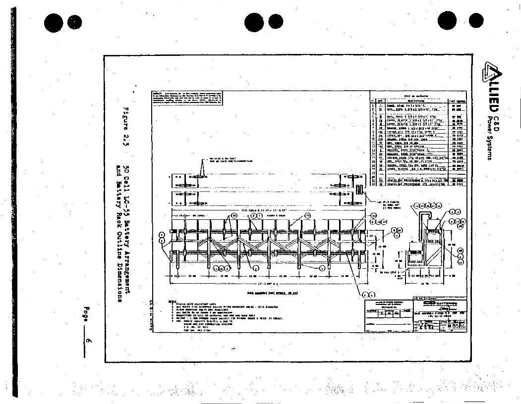
2.2 The two step battery racks consist of steel
support frames of welded angle construction,
insulated steel cell support and restraint
rails, flat steel cross braces and Grade 5
hardware. The battery rack and cell arrangement
is fully described in Drawing No. M-8586 which
appears in Figure 2.3.
Po;• _ 2 __ _
@ J_ • 1.$ 22 • U4 .4.¥4UJ Sli-Sb!WWW.525 El -- .:&& && SUl&ii&W -
·~·· ,.
4LLIED. ~rSystem1
2.3 .The LC-33 battery and two step battery racks
must be installed and operate in accordance
with the requirements set forth in C & D BATTERIES
Section 12-:800, "Stationary Battery. Installation
and Operating Instructions'', and IEEE Std 484-1981.
2.4 Periodic maintenance and testing shall meet the
requirements set forth in IEEE Std 450-1980.
Po;• ...-3 __ _
. -:·.
.....~ :
•
• •
• •
~LLIEl> C&O Power Systems
71~£ I D/M 1U.S W'1Y:' KJ~ o· ••A • ., wir • .... -llOO r" ,., ~ -:@--@-· ·~to ""., '" t"". .r~osr / ·.$ · If.If,
7.$1} I .31J• ,.,.
--I Jir'/~o~lfT ·Z» t/ A::\ ' ~ 1 I u.
l!Jo'f& •:
r.co .. tainu- rn9'ariel •"'•" ba ~•l'tC .. rbof'\•f1.,Dwt if net •v•il•••&,. .... "''°'all 1 ... ,.,ul.
£ .!te ''• Mhr& al" W•·an a..e...tn'1c.a'1a •:
'"'~J. J.1/f'rJ
·s· s.,.. co"t• •"'a.rt-. ti.a. 11•&a. ·c· ""'~c•rl>•n•I• C.•nf•lno.r n bo. 1.11ad. !im.,.,,._: S l'L,O'Z. 'Sa" Cont a\"&.r-
C: 1 'l,O a ,.,.1.,carlboneta c.ol'lta\1'11.r
T.._,. a-•· rc.pl•c•t11. d...,e,a.IC.•11,. k41C:o,• "~0~'9.
...
..
/.• ·11.J,
IO.M
·:::...~:.----
~igure 2.1 LC-~~ Cell Outline Dimen1ion1
~~!CC a:.:: IRW W --·---------------
/ ·" :.;-
Cotltalnar di"'•"•"•"• ·~ ..... 141.09
'. --~«
Po;• 4
• •
I
~LLIEI> C&O Power Systems
C::I:» LC LA
POWER SYSTEMS
9"C.,ICATIONI
~TU -.... -· "--............ ~ ·, ...... . ,, .. •:t CU•:t 1311 """""' 1~-1 ,, .. _I
................... •!. t:t 11.21cr· IJ!,-oet! •:JO!-· t!..3--'
~ .............. . 19·· 17· ~ucr·
IJl!1 ,.."'II l:JO! -! t1J-1
••C•••c G•AVITV . . . . . ,,,,,0 .~ ..... , '"'°' 115Cc1 CC*TAlflil(at , .....•• , ,,.,..~,,,_.,._c
CILL CCVI• .•••••••• n.."'DOU:I,, •PAllATD"I . , •••••• , MIC"OOD'0-4
afT&UdJU~ .• , . , •• , • • Fit:iror.n ·- ,,,rn
ILICTJIOL YTI M(IGMT &ACVI PLA TIS •• , . • . . 2,.U'' I" l ...._.,
•TMO•Alflr&L TualS • • • • TIC DP mu
•CMWUfl •ACf. • . • • • • D.e:l" 11e -.1
TlMa•AU , •• , •. , • , • J.ovr 1'' 17!1 --.1 _..,, DDttl per
C9'•• IC.ODDI"" ........,. are "9D 0"
CIJ'I•• _,.,. 1 I,,."' ll CMlft.1
,,........., .,. ... _.mwww mDft91'*"' '""""'• 91•t'f-Wf • .,,,..,..,.,. _.. ASTM oc:a.. lftG
ULTF"OwDtll 11(·2. O•v~•..a••ASTlll C2"Nl- 70 • 2!...L.
Lead Calcium Lead Antlm.ony
L
.. ,..... c..... .. IG 1.11VPC.n••121°c1 0-811 o........... 1 ... l
r--~~~~"=""~ ... :::~C:..~::::-r::::-::..::¥::::::c.~"'~"":!.:.;'";__~--~~~~~~-'-..... -...... ~~·-... ~-··~· .... · .!~ . .. ~ .......... ·- L.""'·' C--w .,..,,~ .. ..... J .... ·~ JD- ··- ·-LC: ll LA 1J IDO 7]7 l.AJ ... LC l!i LA 1! ' •av. l60 i
1.&J •!><
L: " i L.t. , , 1200 Ml 7.&J
'""' r..c ., L.• 19 ·- 11oe ... nt
LC 1' "' .. ,, ·- •m .... 22t
LC lJ LA 2J •M ·~ 10.&J
":"":":
LC~ LA·J'! ·- ,.,~ ID.LJ . .
"'' 2" r..• 71 ·- ·- 1l.li
ll'
,, " ,. 211 ~ ·- 1.l.11 l"
LC J' r.. .t. J~ 2111 111\ tl.19
J:W:
,, ll LA :C ~ .. ,, ll,.11 J>-- a_......,.-.._....,1~1c~ .. ~11,;JIO ........ _.,,
·0.. ....... -... ... ,,.._-' .,.,., 17'4c1..,, ..... llllllf"i_"2......._
... ::..'.. .. • ~:.;.. - I o.~ ...... ..... •M 1"
11c 2~ ... ..,. f j
1•0 ., . '~ -~ 11•
' ·:-·
:..'~ .. I l'IO ... u .. 1J 72.&J JIC Jr J!i ~'~ ... ,: ·;·
l:!. )O~ ·c..,;. •
3;f; I J7l E<
.!'.\ --.. .. •O~ . -~ . • !I~ ~
~· .,.
-•I ..
I """ IC
.. JE
" •
..
Figure 2.2 LC Type Cell De1ign Characteri1tic1
·peg• 5
••
.,, 0 ti)
•
::-!c.!..:=.-:.;:. -::_--:: = r:=..-: ........ -----~------· --......-.----- ---_________ &-..._._
••
ISi '''"I fMI ~.Jl:.111
9lf'IJ1.IM 11tt• lbl•IMff C•lf . I •n .. ., '"' •l...wH 11<1" nm:9 _.,,.., •• • 111• ••-tu I .,..__,, •• n-....,..t••• O •t -n • • -- I .......... .. ·I ....,111a I• Ill& w .... ,,._ .. Na - ... _, ...... ··-._fun_.,. •.•• ..._ CIMCI. •LC ·U ca.ur . ., ._ NU.ti 11ntt1 aan1.: .. GU" ...
1-..-.11M1;-.V1sH•ll• ' .. -· ,, ... ,. c: ....... ,,, ...
••• ~
ir-1111 • •Hlt.•t• -"
-· ..... ., ... m , .......... l!hf/11_!.. __ - --- ..... 1111._t111LLJJh.J..111a1t...r.1L_. _ ••-
l ' I ii l _-. 1 . ll I .L.. !. _.!L ! •!l.
c
f E . ... • . .IL !! ill-!! .. !! '.!!.
L It:. !L !!-!1-.
-----------!!!l!l!~b:~~-~-
--·- ----·---
3.0 PERFORMANCE REQUIREMENTS
3.1 The battery, when installed and maintained in
accordance with the guidelines eet for~h in
C & D BATTERIES' Drawings an~ Ine~ructione, and
the IEEE Standards 450 and 484, shall remain
functional for -a period of 20 years from the
date of shipment.
The battety shall, at any time during ite qual
ified life, be capable of supplying the specified
design loads without the voltage at the battery
terminals falling below 105 volte while exp~r
iencing any single o' combination of the follow
ing environmental con~itions.
a. Ambient temperature range of +77°F to +90°F
and an annual average temperature of +80°F
or lees.
b. Relative humidity from 0'1. to 100'7..
c. Seismic events of the apecified intensities.
• 3.2· The battery racke shall be capable of aupporting
~he battery celle and their interconnecting
Page _._7 __

•
• •
•
3.2 (Continued)
devices without damage or interruption of circuit
continuity, and ehall maintain structural integrity
~nd eupport function throughout the life of the
battery, and during and following specified
Operating Basia and Deeig'n Basie Earthquakes •
Page __ e __ ·~
1--
• •
•••
4.0 ENVIRONMENTAL QUALIFICATION
4.1 Electrical
Since battery capacity is increased ~t temp
eratures above 77° F, and decreases at temper
atures below this value, the worse case condition.
for the battery to deliver the specified design
currents is at th~ minimum battery ~oom.ambient
temper at u re of 7 70 .F •
The battery must also be capable of supplying the
design loads throughout its qualified life, and
therefore must have adequate design margin so that
if capacity has de1raded to 80~ of the original
published ratings (erid of service life), the
desi~n loads will still be supplied for the pre
s~ribed tim~s without battery voltage falling
below the min{mum specified value ~f 105 volts.
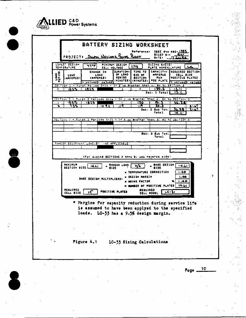
Battery sizing t~lculations are shown in Figure
4.1, and show the LC-33 battery has adequate
margins to ~eet these requirements. For ref
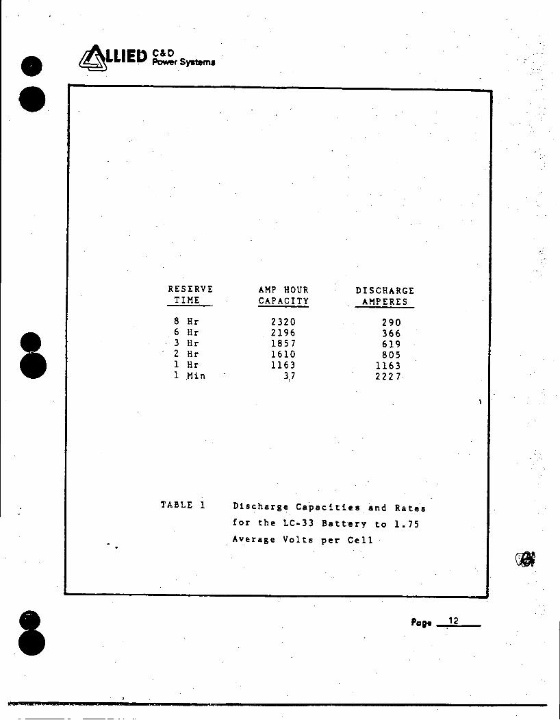
ete~ce, the LC-33 celi discharge characteristics
are shown in Figure 4.2, and selected capacities
~o 1.75 average volts per tell are given in
TABLE 1.
Page _-..9 __
. . _:,. -~
.. -~ .· . '
• • 4LLIEL> ~rSystems
BATTERY SIZING WORKSHEET lefOP'O,,COI
F'ROJECTI 5w:u. Wc.1..t:a.L ~au'1r Yc.wr
'-""'l!~ t'[SiC1H I ,,.,.I "IH%11U'I DU!GN I l:i~ I T["~llh,1 •.II'[ CE:.L uo~ UG[
Cl CHANGE JN l)Ulll>TJONI TJllE TO tA~MtlTYI t£0Ul~[0 IECTIOH Cl 0 LOAD LOlllD OF LOAD IND DF ·-0 IL \AIU•[l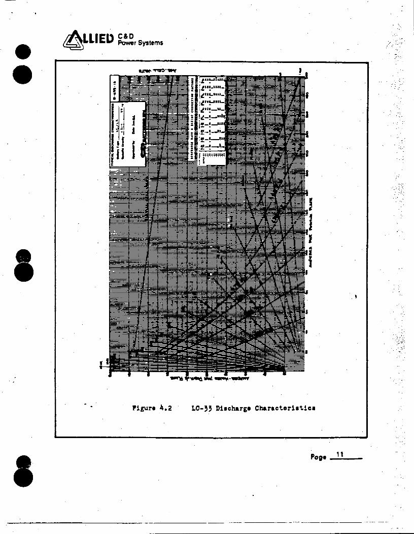
• •
I
..
I
aLLIEI> ~.systems
Pigure 4.2 LC-'5 Di1charg• Character11tic1
Page_,, __
-------------------~--------···---·---
.>'
·. < .
• ••
I
(\LLIED ~_systems
RESERVE TIME
8 Hr 6 Hr 3 Hr 2 Hr 1 Hr 1 Min
TABLE l
AMP HOUR DISCHARGE CAPACITY AMPERES
2320 290 2196 366 1857 619 1610 805 1163 1163
3,7 2 2 2 7-
Discharge Capacities and Rat~s
for the LC-33 Batt~ry to 1.75
. Average Volts per Cell ·
Page _.-12~-
•
•
•
4.2 Battery Life
Twenty year qualified life is based on previous
natural and accelerated aging tests concucted on
LC cell types of identical and similar material
and design.
All accelerated (thermal) aging.was conducted at
a controlled test chamber· temperature of 160°F
+2°F~ The test cells were float charged at this
~emperatur~ for a period not less than 200 days,
which i~ the equivalent of 20 years service at
a 77°F operating temperature. This is in accord
ance with the IEEE Std 535-1979 aging factor of
10 days equals one iear for le~d calcium cells.
After thermal aging of the test cells, capacity
testing was conducted at discharge rates identical
to those prior to aging. Capacity at th~ end ~f
the thermal aging program remain~d greater than
soi of the initial published ratings for all cells.
Original C & D BATTERIES test data, as summarized
in TABLE 2, confirm these aging fa~tors. The
tests were performed on new and field service
lead calcium battery cells during a period
Pa~ _...1 ''---
. ..... '·,··
• 4LUED ~sy81em1
4.2 Battery Life (continue~)
between 1959 and 1967 and confirm the temperature
versus life. relationship for the lead acid, lead
calcium alloy battery. A graph depleting batteri
life versus electrolyte temperature ls drawn from·
this test data and is shown in Figure 4.3.
Included as part of the qualification ~r~gram
that forms the basis of this report were naturally
aged (25 years of service) lead calcuim cells.
, 14 c;e----
I~
•
•• •
•
IA1 LIED C&O ~ Pow9r Systems -
'J'[~:1™.Tt.'P.E. OF TtST
160°r 160 160 160
145 145 '145 145
, ,50 1,50 ,,o , ,50
, 15 115
TABLE 2
I.In, A'J' I.In, CAI.Ct:-'J't.?.:n!\l Tt.'R!: LAT~ I 77°1
0.55 21.2 0.5~ 20.~ -c.5, · 1;., 0.55 - 20.1
o. 76 , l+ .5 c.79 15.~. o.;4 1)., 1. 02 21.c
2.15 22; ! . 1.9~ 20.0 2.,~ 24., 2.,0 2,.e
4.05 24.0 4.0S 24.C
Life Testing Results _For
Lead Calcuim Batteries
Page 15
··-·
...
,_
' ~·
- :,... .
;._.~ _::·.·;
• •
•
•
~LLIED ~rSysteml
I i I
Pigv.re 4.,
~,. .... ,
Batter)' Lit• Tl. T•mperatur•
.Po;• __ ,_6 __
• •
•
•
4.3 Seismic Testing
Seismic qualification of the LC-33 battery is
based on.previous qualification t•sting of vario~s
LC type baitery cells including the LC-33 cell.
Seismic qualification bf the batt~ry rack is based
on 'previous testing and analysis conducted on a
two step battery rack identical in design and
material as the Salem battery rack. Figure 4.4
and 4.5 show the two step test rack and mounted
test cells as it existed for simulated seismic
testing.
I ,
The construction and o~erating characteristics
of ~he tested battery cells are identical to.the
Salem battery. Component location and material
employ the same overall geometry to carry loads
as the Salem Nuclear Generating Station LC-33
battery. For a comparison of the battery cell
dimensions and construction features between
the Salem LC-33 battery and the seismically
tested cells upon which qualification is based,·
refer to Figure 4.6.
Po;. __ 1 ... 1 __
'· . ..
••
-----~-WWW
-·-·-·-· --'-t2=> --·-- --- ....... _..,_
--·
-.& Ill • ft • t/I ·t --.Ma ... S--.D'9DMI "ft.Ill ... • -···• u· a.a....·....,
., an .u 11!1,~T:
••
........ 1~"-··· ·1n .. '1.111111 -·--•• .......... __ _ ·---..... ~ ..... ·ne n,. • •• • ._ _... ·1 ·~ ---... -~ ...
co ....
• OI 0
~ A.
., • ... .... •J e:"' ... " 0-4' ~
• -0 0 Ji ;.:; • ~ ~.,
u. •1-4 ~
~2 •:JI: ... .. n.o ..... +' (l'J ID
..... o .... ,. u l-<O
4
4
• .. ~ ...t ..
• •
•
.,, 0
Q
•
\()
.. ... ~ "t G
J:-• \JI
0 ""' II C t-J 0 t-J . .,.
c+ "11. Cl 0 'U "t ... ·~
.. • c+
·o-1 ::d ,. .. n
• ~ c+
~ c ...
0 r+ ::r
~ .... °' I\) ~t4 -o I I .... \Jil
\Jil
• ~· --- -·-· .. --J;;:"-::L-:..:..-..:.:::.-z::-.:
T~i~·1a.l
A a:VlW>t'\-ttE.~ Ux.Q-r .o-n
.1-.. .. -L-..................... . 1-----··· ---
" ' ' -
, .: ~ .-. · .... . ;.!' >.-.
······-
• ~ ... -m c f ~ ., UJ ~ ii 3 "'
:-,·
~~,.: ... . .. ~
.. : .. . . . . ·•· ... .. : .... .... t .• .. . '... .
• •· . 4". •.
••
..;-·
. ·
.• ; _. ft
7,,.· ·' :.:·
...
JJdJ/t-
. . ..
• .. .. '· . . - ~.: .. . .
•
)
1 • Cll 0
A.
"' "' I 0 ~
... 0
'" 0
~~ .,.._ ~~ •O Q
i:i~ 0 ... ........ ~ .. u.,... i! ~ ¥ cs; • r= -0
8 ~
'O • ..:t
D ... ~ .... ..
• • ~LIED ~rSystems
4.3 Seismic Testing (continued)
For the purpose of this report we will compare
test data fr~m two previously conducted seismic
qualification test ~rograms. The battery cell
types seismically tested are listed in TABLE 3.
20 Po~----
··,;. :::,-,
. . './:;:
· ....
. ·
I
...
• •
•
• •
4LLIEL> ~rsystem~
WYLE TEST NO. 43450-1
CELL .TYPE CAPACITY RATE
4LCY--ll (unaged) 1 330 AH 1 Ht. LC-15 (unaged) 2 1050 AH 8 Hr LC-21 - (20 yr thermal) 2 1500 AH 8 Hr LC-25 (unaged) . 2 1800 AH 8 HR
.LC-29. (unaged) 2 1008 AH 1 Hr LCY-39 (uh aged) 2 1330 AH 1 Hr
-CT-1440 (25 yr natural) 2 1440 AH 8 HR
WYLE TEST NO. 46661-.l
LC-33 (unaged) 12 1816 AH 4 Hr
* SAN is Styrene~acrylonitrile PC is Polyc_arbonate
TABLE 3 LC Type Cells Seismically Proof Tested i~ Two S~ep Racks
JAR MATERIAL * -----
SAN PC PC
SAN PC PC PC
PC
l·
Page ___ 2_1 __
. -~ , ::. -...
. ~·· .
~ -.
• •
• •
•
4LLIED ~rSystems
4.3 Seismic Testing (continued)
The CT-14~0 cell type referenced ·in TABLE 3 was
a 29 plate cell, 25 yea~ old at the time of the
seismic test, that was manufactured lri 1951 as
part of a 60 cell lead calcium battery. At that
time, the cells were encased in hard rubber jars
and had a nomenclature of RCT-1680 rated 1680
ampere hou~s at ~he 8 hour rate of discharge t6
1.75 average volts per cell. The battery was
purchased by the BELL TELEPHONE SYSTEM and install
ed in their Pennypacker Exchange Office in Phila
delphia, PA as an emergency power source, where
the battery operated fer 17 trouble-free years •
In 196~, when the Ex~hange was being enlarded,
the battery was re-aquired by C & D BATTERIES.
It was stored for one year until the Plymouth
Meeting, PA headquarters building was completed,
and, in the spring of 1910, it was installed
there for use as an emergency lighting system~
For the purpose of this test and for future
visual observation, the elements of two cells
were removed from their original containers and
placed in transparent plastic containers with
plastic covers, and a bottowm plate support
system similar to that employed in currently
Po;• __ 2_2 __
.''1.

• •
-• •
• •
4LLIED ~systems
4.3 Seismic Testing (continued)
4.3.1
produced LC type cell~~ In or~er to facilitate
the jar transfer, two positive plat~s and two
negative pl,ates were removed, de-rating ·the cells
from 1680 AH to 1440 AH capacity.
The seismic t~st results as they ~pply to this
report are discussed in the following sections.
Effect on Battery Capacity
The IC type battery cells, including the LC-33,
seismically tested w~re subjected to capacity
tests prior to, ·and following the seimic test
programs. These capacity tests were· performed
in accordance with the applicable precedures
described in IEEE Std 450.
All unaged cells were at 1001~ or greater, rated
capacity prior to the start of the test program.
and remained so throughout.
All aged cells retained capacities. greater than
80% of publi~hed ratings throughout the test
program •
. Pop• -2-'--
W %!Q%N4_JMJ&§ULW _ _&I. 2.iM!iPWW-1 $ktJA»;!!4Mi41¥,{QWWWJ1¥1W41SP4AAJS £&&6&54 XLEEm!t&L_
- -~'
··~·· .
. !. ---
•
• •
•
4.3.1 Effect on Battery Caapcity (continued)
ATTACHMENT 1 includes the pre-seismic and
post-seismic capaci~y test results for each of
the cell types tested.
4.3.2 Sesimic Test Procedure
Sixteen cells, from the largest to the smallest
of the LC type, including the naturally aged
CT-1440 cells were mounted in the nor~al manner
and- connected in series on a two step battery
rack. This battery arid rack assembly was then
subjected to simulated seismic testing at WYLE
LABORATORIES in Huntsville, AL, with results as
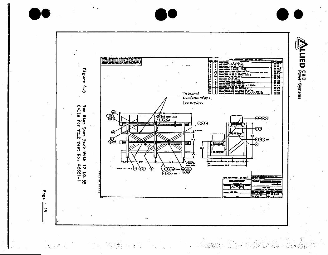
given in WYLE Test Report No.- 43450-1.
Twelve LC-33 cells were mounted and interconnected
in the normal manner in a two step battery rack.
The cells were then subjected to simulated seismic
testing at WYLE LABORATORIES in Huntsville~ AL,
with results as given in WYLE Test Report .No •
. 46661-1.
Each of the test racks were mounte~ dir~ctly to
the WYLE test table:
For WYLE Test No~ 43450-1, the rack assembly
Po;• . 24
• 4LLIED ~Systems
4.3.2 Seismic Test Procedure (continued)
was bolted directly to the test table at each·
bolting location in the rack foundation using
1/2 inch SAE Grade 5 bolts. This piocedure was
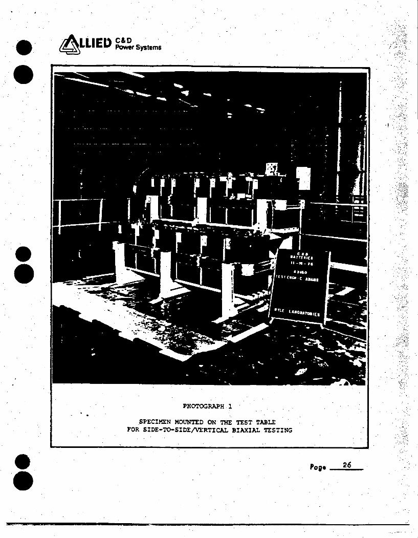
used f~r each test orientation. ~hotograph 1
shows the test rack and cells as mounted on the
WYLE test table.
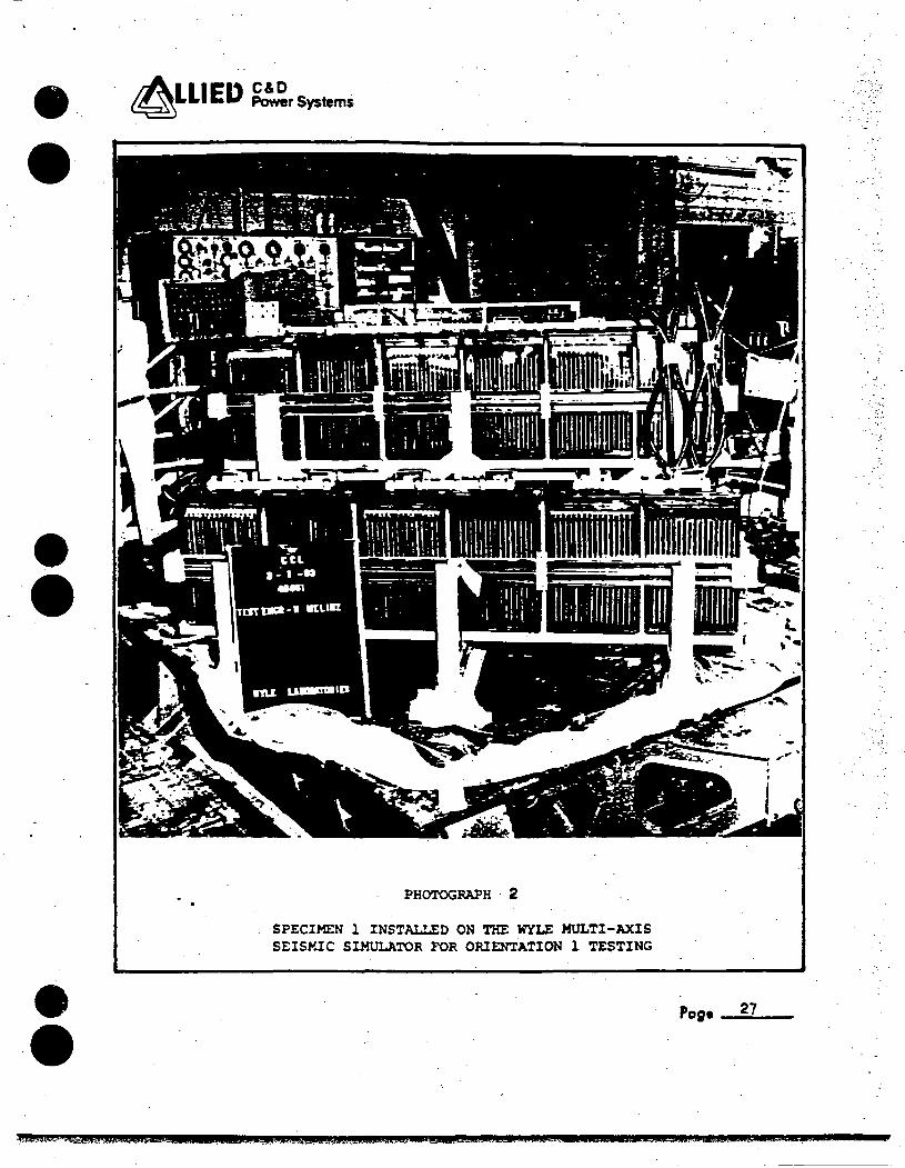
For WYLE Test No. 46661-1, the rack assemtly
was ~elded to a separate WYLE tube steel test
frame using 3/16 inch welds 4 inches long or
shorter. There were 24 welds on the rack base
using E-7018 low hydrogen electrodes.· The test
frames were welded to the seismic table with their
longitudinal axis at 45 ° to the table's direction
of motion and were symmetric with the table's r
center. Reference Photograph 2.·
One vertical and one horizontal control acceler-
ometer were mounted on the test table. T·RS p 1 ots
we r e t a k en f r om tl, e s e c on t r o 1 a c -c e 1 e r o in e t e r s a t
the time of the tests for each axis.
The battery rack and battery cells were instru
mented with horizontal and vertical response
accelerometers in various locations to determine .
equipment responses.
Pc;• 25
·•
• •
• •
IA.1 .ED C&D . . ~LLI . Power Systems
PHOTOGRAPH l
SPECIMEN MOUNTED ON THE TEST TABLE FOR SIOE-TO-SIOE/VERTICAI.. BIAXIAL TESTING
'",, ·.-
•7' •
. ;.·,~:
.,-_· ..
- ..... ·
Po;• _ _.2;.;6;..· -
• •
• •
• •
,.
~LLIED ~rSystems
lli:l>il/11/W - --
PHOTOGRAPH · 2
SPECIMEN l INSTALLED ON THE WYLE MULTI-AXIS SEISMIC SIMULATOR FOR ORIENTATION l TESTING
Page _11.
·~~~}'W5"AQl@llSWA ME JU& _µ:;;;:tR?SMJ?&!4$A5..-ta;_e;;:mzJA¥Wd3lSWti UkUC.t ;s a;w z .. www z aw 1wa:a&wa01ssa.a;,:::::m
'·~
.. ~;;, ., ..
.. ,,_,
-.... _
• •
•
•
4.3.2 Seismic Test Procedure (continued)
The battery cells were connected in seri~s to a
resistive load of approximately 20 amperes during
all phases of the seismic 'tests. The battery
output voltage and current were recorded on an
oscillograph .recorder during the seismic test
programs. These monitoring channels were used
to determine electrical continuity, current and
voltage levels, and to det~ct any spurious
operation before, during and after the test
programs •
Testing consisted of a low-levEl resonance search,
follow~d by random multifrequency qualification ' tests. Qualification tests consisted of five
(5) Operating Basis Earthquake (OBE) tests prior
to one (1) Design Basis Earthquake (DBE) test.
The duration for each test was 30 seconds.
ATTACHMENT 2 contains the WYLE Test Procedure,
Transmissibility Plot, DBE Test Response Spectrum
a~d Equipment Calibra~ion LLst for WYLE Test
No. 43450-1.
28 Po;e ___ _
WPM!4'i!\llQiilMP$MLIOSU a J Gttut§t\4{:; 4!t!4¥W4Bilt£$V.WZAAW4U! Ul,UQLSJ#AWl&il$ . . a ;_
.J
•• -·
• •
• •
4LLIEI> ~systems
4.3.2 Seismic Test Proc~dure (contiriued)
ATTACHMENT 3 contains the WYLE Test Procedure,
Transmissibility Plot, DBE Test Response Spectrum
and Equipment Calibration List for WYLE Test
No. 46661-1.
Po;e. __ 29..;..._
/ I
· '*&;;ss.w:uwM\ttm;:;:uam_e .t¥ :&&# mu. mrz.wm.a;;:.JJS4A4WWWlMQ46&4t1i1MHi'.£ZML&t .uz:aacLE _ .. ta .... ass
·.; ..
• •
I
• • ·ax>u an:
AL.LIED. C&D ~ Power Systems
5.0 T&ST RESULTS
15
The battery cells and the ~attery rack successfully
completed the simulated seismic test prograroe. Test
results and post~test inspection showed thai they
vossessed sufficient integrity to withstand, wi~hout
compromise of structure of function, the seismic test
environments. The oscillograph records did not indi-
cate ~ny spurious or improper operation or deviation
in the output voltage/current levels of the battery,.
either during of after the seismic excitation.
Post-seismii.capacity tests conducted on the battery
cells yielded capacities essentially identical to '
those reco~ded prior to the seismic test programs.
Unaged cells retained ~apacities of 100% or greater.
-The 25 year old naturally aged test cells delivered
capacities over 80% of their rating.
Although these qualification programs were not
specifically performed as proof tests for the Salem
battery and battery rack, its applicability is demon
strated due to the identical design of all LC type
battery cells and two step battery racks.·
Po;e __.,._o __
M4¥ EL = di SU I
.. ' .... ~
• •
•
• •
c(\LLIED =systems
5.0 TEST RESULTS (continued)
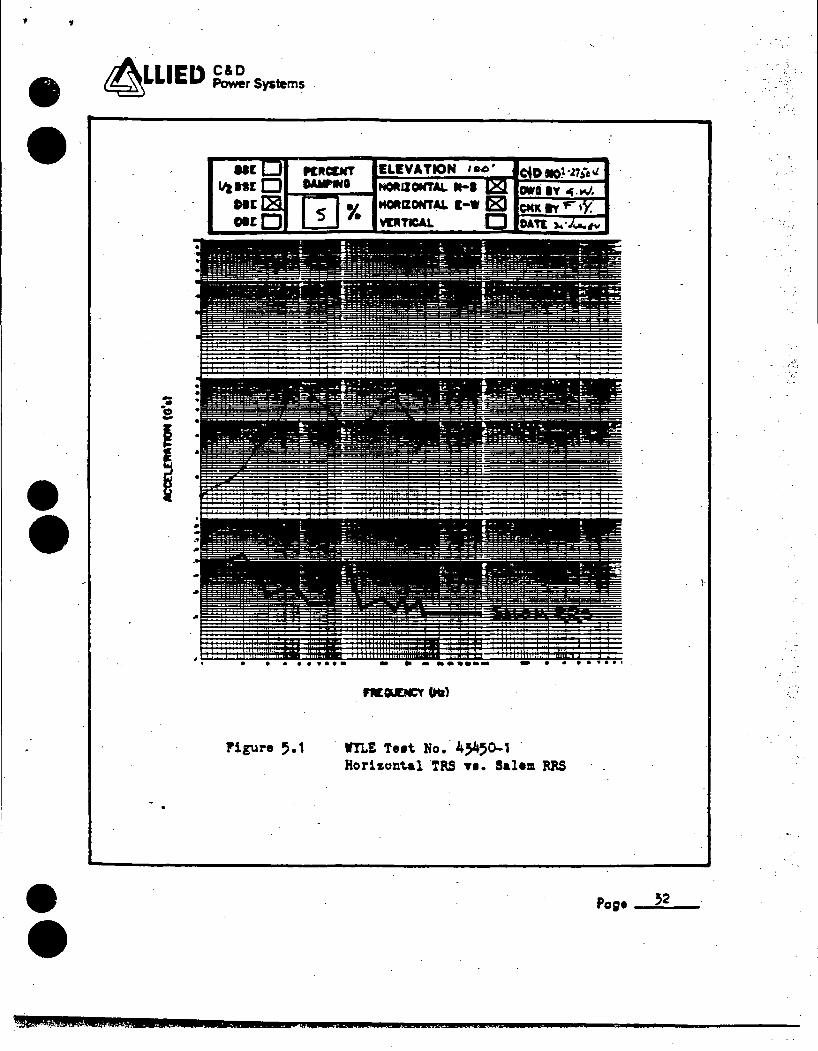
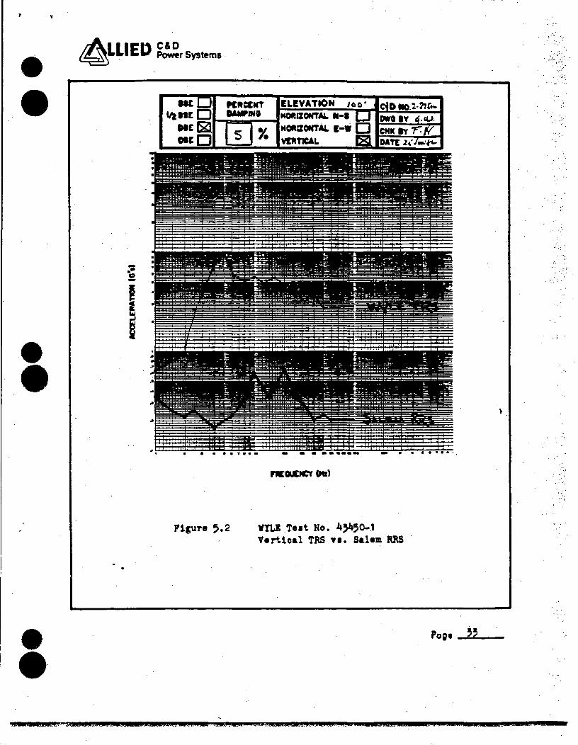
The WYLE seismic Test Response Spectra (TRS) from
Report Nos. 43450-1 and 46661-1 completely envelop
the Salem R~quired Response Spectra (RRS) at all
test frequencies, therefore these tests will serve
as a qualification for the LC-33 battery ·and two
step battery rack. Figures 5.1 through 5.4 show
the DBE horizontal and vertical TRS from both WYLE
tests versus the Salem RRS •
Page --~-1--
wwww.nr;wwwa WM&¥' C& au I
' .,
• CLLIEI) ~rSystems
•
• • tM .QWWWW.i a
Pigure ,.1
q ijj1
W!LE Te1t No. 454,0-1 Horizont.al TRS Tl. Salem RRS
a xmamsa .SSZlt ma
l·
Pc;• ~~:5.;..2 __
:-·:
~ .. : ..
. ··.'
.,:t •·.\
• ~LLIED ~rSystems .
• •
• • kWWWZUMIM.PJ• !JtAtGIZ_ tac 12
I
ELEVATION
. . .. ., ... - - • • I •••• I.
Figure 5.2 VYL1 Tut No. 4)450-.1 Vertical TRS Tl. Salem RRS
L&CE.AJ#JW&ii .M48A.t4St !, . t..iC&utZAi#A.k)QhC .. 44¥C- .ZWCPA&.
Pog1 --'~'--
4.Z:XSXUMI S§AQ
··:_
. " .·,
• ~LLIED ~rsys1em1
-•• c -I I
• • • •• 9 •• -
Figur• 5.5
•
ELEVATION
- . --····-
WYLE T•1t Ro. 46661-1 Horizontal TRS v1. Salem RRS
• ~j '
...
Pop• --=~;.,__-
$42&;A£2ML?Z&U4A42 2:. 44MQt .QL JQW#QXCJJl&C@$&2$UJUC;kQJLJSMkAG$.JCJJC !. !ASUGii#UE LL
i '
• •
• •
• •
4LLIED ~rSystem~
-•• c -
I
ELEVATION 100'
. . ..... . - -. --···- - • • •• ., •• I
P'igur• 5.li WILi Te1t No. 46661-1 Vertio&l TRS Tl. Salem MS
Po;• 5'
•
•
•
6.0 CONCLUSIONS
The 125 volt, 60 cell LC-33 battery and two step
battery _racks are envir6nmentally qualified for a
period of 20 years, when maintained in accordance
with recommende~ and approved·procedures, for
~ervice in a mild environment outside primary
containment areas of the Salem Generating Plant.
Previous Nucl£ar Environmental Qualification testing
of LC type battery cells and two ste~ battery racks
demonstrate that they possess sufficient design
margin and integrity to withstand without compromise
of structure or electrical function, the environment
of the Salem Nuclear Generating Station. . ~
Pa~ --.56 __
WAW&wamzw.:.aa •&&&•UAW. mas ozrn a
/ "
• •
•
•
4LLIEL> ~rSystems
7.0 JUSTIFICATIO~S
7.1 Battery
The Salem LC-33 battery is qualified by
similarity based on type test~ng and by actual
testing of the LC-33 battery. The test programs
included unaged and aged battery cells.
TABLE 4 shows the physica) similarity of the
plates of all the test cells •
PLATE llOKEllCLATUltE
CT
LC
LCY
TABLE 4
PLATE BEICHT .!ill!! TBI CJUliE SS
13.25 11 11. s" 0.266" (Poi.), 0 .180"
15.00 11 12.0 11 0.312 11 (Poi.), 0.210 11
15.00 11 12.0" 0.250 11 (Poi.), 0.180 11
Compari1on of LC T1P• Plate1 Sei1mically Te1ted
(Neg.)
(Neg.)
(tilg.)
P 57 a~----
W!&L .. :..::. .t· .... .. .. .. ,.. ' . SJ U40 X!£1&WltZ&S4 WY!&.
• •
• •
•
~LLIED ~rSystems
J.l Batt~ry (continued)
All test cells were constructed with lead
calcium grids and employed equal or identic~l
construction materials and features.
Comparing the Salem LC-33 battery with any of
.the LC type cells and pariicularly with the
naturally aged CT-1440 t~st cells is justified
because degradation (e~brittlement} of the
positive plates is the predominant failure mode
in lead ac·i~ storage batteries; and since the
float charging current is proportional to
positive plate capacity - and life .is pro
portional to positive p~ate thickness - the
corrosion rate of the plate grid structure will
be identical and the CT-1440 and LC-33 battery
will degrade at the same rate since both posi
tive plates are the same material ~nd design.
The thickness of the CT positive plate is less
than that of the LC positive plate, therefore,
the ability of a naturally aged CT-1440 battery
to successfully withstand a seismic test demon
strates that a naturally aged LC-33 would be
able to withstand the same seismic loads since
the CT plates are in a mechanically weaker
' condition. The testing of unaged LC-33 cells
'8 . Pope-----
.:. .• ~ .. ~."'-~. ~ ~s.~ lf;f·F ~i"'·~~ .. :· ·v~ .• ~ .. "•-Iii~.·,,.""~··.··--~-~....... .·~.~ ...... '.'., .. , ... ~·.· "'* • ............ I ,. • .. ~--- !~., • '
•• •
•
• •
7.1 Battery (continued)
is th~refore justified by the successful. co~
pl~tion of the seismic test by the •ged CT-1440
battery cells.
Non-metallic components: polycarbonate cell
cont~iners, ~tyrene cell covers, polystyrene
flame arrestor vents and cell spacers, poly
ethylene rack rail cov~rs, ~nd the 600 volt
900c rated neoprene insula.tion of the interstep
cable connectors are judge~ to be age-insensitive
to the mild environrr.ental conditions of the
Salem battery room, .and will have a qualified
life e~~al .to that of the battery plates.
Metallic tomponents such as the steel battery
rack members, the coated and insulated copper
connectors ind the co~necting hardware are
known to be age-insensitive to the specified
environment and will have a qualified life
exceeding that of the battery plaies.
7.2 Battery Rack
Qualification of the Salem batter~ rack is.
Page __ 5_9_
'',:··
..· , ... ,.
, ~ • _, • \ ' , • *' .~F' ., ") • •• .... ~ <.: • ~ • '• • 0 •~ ''" • I • :\. •, t• : ... ,_ • • ~ ~ ' - • - I" • " ~..- I • ,"• • 0 -",o: •• • ' . ••
• •
• •
•
7.2 Battery Rack (continued)
b a s e d on s i m i 1 a r i t y to a -rep re s e ·n ta t i v e r a c k
previously tested.
Justif icat~on fo~ testing a two~bay r~ck to
qualify a six-bay rack is accomplished by .show
ing the structural behavior ~f a ~wo-bay model
to that of a five-bay model. The results from
two finite analyses from Reference 4 are com~
pared to demonstrate seismic equivalence between
typical two-bay and five-bay racks. The finite
element analysis were performed using ~he com-
puter program STARDYNE • STARDYNE is a well
known, well documented proprietary computer
program widely accepted for this type of analysis
by both industry and tte Nuclear Regulatory
Commission.
The results of the analyses compared are the
equipment natural frequencies and beam stresses
from statically applied 1.0 g seismic loads in
each of the three directions. These results are
chosen for comparison because they present the
dynamic and structural response of the math-
imatical models. The complete results, ·with a
description of the analyses are co~tained in
Reference 4.
, 40 O~----
• •
I
1·.2 Battery Rack (continued)
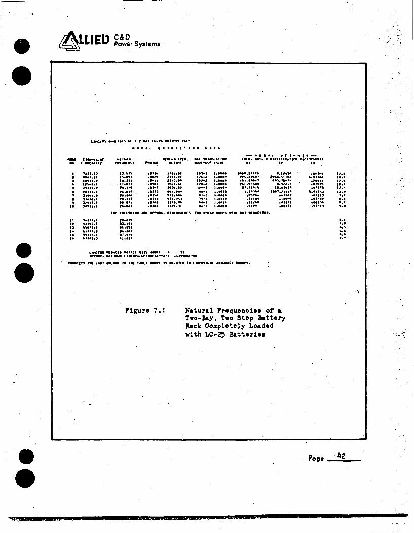
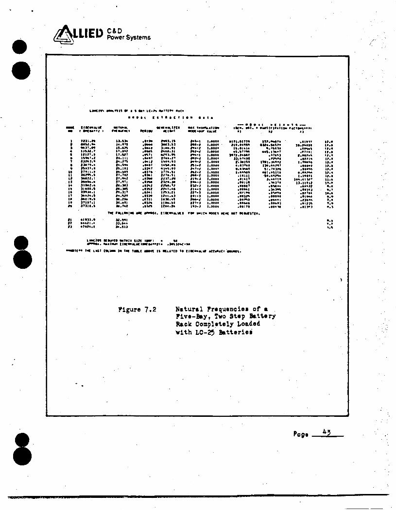
Figu~es 7.1 and 7.2 present the natural freq
uencies of the two-bay and five-bay mathematical
models. The natural fr~quencies closely agree,
and thus, the battery racks for the Salem Gen
erating Station will have natural frequencies
equal to the tested rack.
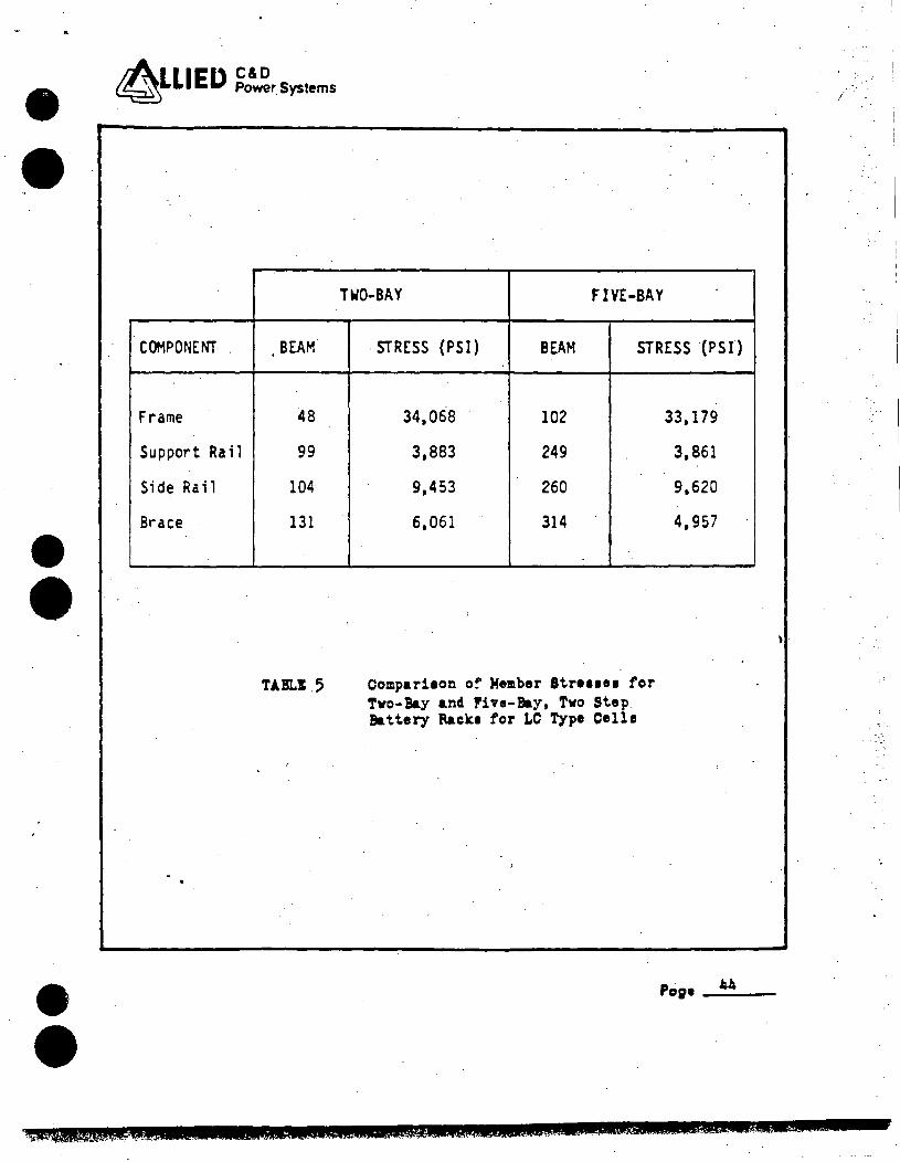
TABLE 5 presents a comparison of the beam member
stresses. The three directions of seismic loa~
were combined by the SRSS m~thod. No appreciable
difference in stress occurs b~tween the two-bay
model and the five-bay model._ Each bay has
identical bracing in each direction. Additional
bays_ provide their own bracing. The WYLE TRS
are shown to completely envelo~ the Salem RRS,
therefore, the two-bay rack is structurally
adequate and represents accurately the behavior
of the six-bay Salem Genera~ing Station battery
rack.
Po~ ___ 4_1_
_/· / - .• ·~ .
- ·· ..
• •
•
• •
~LLIEO C&D Power Systems
--• • • ' • • II
II It IJ •• .. ••
XUZ&IWA
Lalltlft _. ftll~ ti9 I I Mt I C•llt .. flt et ••< ..
........ ur I 911t:WHI I
•nr. u -··" ll~•J.I ·-··· ..... , .. 6IJPJ.1 JI .. , •• ........ .,.,, .. '"Jlol
,., .... OMJ,I .,..,..J.1 ... ..,., ......... . , .. ,.,
••1ta& 11t•1Ct I• vita
... ""' .. •lll-llC• u.•~ l'•"I ... ,.,
: . , .. , . ... .... ...... "·-n.Jlf n.1re ..... ,
•••M.tnn. a.a• t•~••I .. .. .. ~ .. ..... --- '"'"' .. ,,. 1,n.11 1n-1 •••••• ... ,. ""··· ,,._, •••••• ...... IJfJ.H .,,_, •••••• ·-I .... ,.\1 ., .. , •••••• .. ,., ru1 • ., ,,.. .. . ...... .. ,,, ~-'"
. ... , •••••• ··- ., ..... •l•J •••••• elJ:llJ •r..rn '~·· ...... ··- ..... '" --:. • ••••• .. ,.. 119',JI .... • •••••
_.,. .. , ., ...... ,_ Ill•• .. le • 11 .. U, l•tTIDI •ir1.-.•••I
II '' IJ
--··'"'' .,.. .. ,,.., . .. , ...... .... -''·····~ .........
ee\11• . ... ~ ·••rt• ,llMI
... ,..,. .............. ....... ,. ,,,,, .. ,,,.,.,, . .. ,.,. ... ..... , ....... ...... .... ,,
... -... ,,.. ., ....
.tta9' ..,,,, •·•1 t4J ..... J . ..... .... ,. .... ,.
,,. r-.L .. ,,. ... -•· 11er .. 1o1.un '°" ... ic" -• "'"' •• 111-IYH· .. .. ,. JJ,IH ,.,,., ...,. . J•.••• ......
L-nl llleoll:H .. , ... llft 1-1 • JJ .,... ...... ,.,. 11• .. -.ur••w••1t• •• ......, ...
P'igure 7. 1 Natural Pr•queDci•• of a Two-B&y, Two Step Battery Rack Completely Loaded with LC-25 Ba.tteriH
•2&U oz&a:us E&i&E&&ll CLE
Po;•
., .. •••• • ••• •••• •••• •••• '·' . .. '·' .... ••• '·' ... .... .. .. .,,
.·".
·~· ..
·~
., . ' ~- ,· .
• •
'
~LLIEl> C&D Power Systems
--I I J • • • ' • • .. II II IJ ,. II •• " ,. ,. " " II ,,
L-.Ctft ..-.nit er I I .. , LC•".._,,,.,. ••t• • e e I l ..... ,,
111r .. 11.ur .. , .... •••&lllD t ....... ,. , ..... ""' "'91•
-·~' HJI ... u.n• .. ,,. -J.11 uw ... ····" ·- )NJ,U .. , .. " ... ~ ·-· JI Mell llUl,7 "·"' ·- ..... ,. '""·' 11.wt .... ,. wu ... ·~'·' "·"' .... , ... ,.,, I>,.>•• ···'" ... ., IM•.tJ l>I"·· •.. ~ .... ,. ....... "'"·' ft,lf) .. ,., ••·~·•e , ...... ... "'9• .. , .. . .... ,. ,.~., ''·"' .. ,., '""·" Mall,1 ,, ... , ··- ,,,,,n -·· ''·''' ··- nra.:ie , ... , .. ... ,., elhl llM.11 , .....• ... - •'"'' ,,.,, .. J:to.M.I "•JIT .. ,,. , uu.11 ,..,,. .. ... - .. ,,. ,, .... , ........ ,.., .. elJJI llMe•I lfllT,1 ,. .... ol>h ., ... ". Jnu.t 11. ,., •• u. l~H.h
• • .. ' . .. , t•M'W.UI ...
--• ... ur ..... '·"'' ..... •••••• ,. .. , •••••• ,.,., '·"'' ,..., ''"'' ,.,.., •••••• .... , •••••• ftl•I •••••• .... , ...... .. ,., ...... ,..., •••••• ,. .. , •••••• , .... , •••••• IJl•I •••••• II••> •••••• ,,,_, •••••• 111-J •••••• .... , ...... ,,,_, ...... ,,,_, ......
-····· .. , .. ,,_ 11if•, .. ,. • ... , It 1•1tl01r ract_.. •• ,. .. ., . , ........ " "'·""" . , ...... ·'·"'' .. ,. ....... .. J>.•ilM r.,."' ... ,, .. ... ,... .. ...... ...... ..... ,
eHtle . .... , ...... .. ,, .. ·••11' ........ . ..... .... , .
,,, ..... ,. ....... ,,. ...~.,. .. ,, .,.., .... ,,
el'f'AI ..... ,. .. , .,. ...... , ..... ,,. ••••••••• . ..... ,...
J ..... . . ,..,,, ....... . ,.,.. ....... •••••• . .... . . .... , .... "
..... ,, ......... ...... , ...... •... ,., .. ,,, . ,,, .. ,, • ••••• . .. ~, ····~ • • ••••• . ..... ,,,
u.11•11 . .. ,,, ·••>•J .., ... ....... .., .... •'''" ... ,.,
flor '"-L•I• - -&, ll ... Al. .. I , .... 1c. _, 11(11( eDT 11(-lfln.
11•n.• ... , ... .,.,.,, II.Ml ,,, ... . ,. ... , LeMtift •lll'TI .. ,. .. llft t-1 • W .......... ..,,,.,. 1:1••11L.wr1 ...... , ••• ,..,,.., ...
-u•• roe u11 ca- •• •• ••r - " •LUlD •• u ....... tea111•t• ·...et.
l"igure 7.2 Natural rrequencie1 of a rive-Bay, Two Step Battery Ra.ck Completely Loaded with LC-2' Batteriel
Po;•
., .. • ••• •••• •••• •••• .... .... .... ., .. II·• .... .... •••• ... ••• • ••• . .. '·" ... .. ,
. ... '·' •.\
• •
• •
•
·.
~LLIEO ~~r.Systems
COMPONENT . BEAM
Frame 48
Support Rail 99
Side Rail 104
Brace 131
TABLI .5
------- --
TWO-BAY FIVE-BAY
·STRESS {PSI) BEAM STRESS (PSI)
34,068 102 33,179
3,883 249 3,861
9,453 260 9,620
6,061 314 4,957
Compari1on o~ Member Stre11e1 for Two-Bay and Five-Bay, Two Step. Battery Racki for LC Type Celle
Po;•-"--
) .
,\iMIMi.WWWil!WS&l& '··I . PJU!AlW.USZ!&i !.U .. i& JQJ,WWWUW!lanzz&&LZNi&.U& 2 I i
< ,• .-
•
•
I
•
4LLIED ~rsystema
8.0 LIST OF REFERENCES
l~ PUBLIC SERVICE ELECTRIC & GAS CO., Purchase Order No. 923023 dated 22 May 1984; Specification No. 72-1308 dated 27 December 1972; Specificatio~ No. 68626 dated 15 November 1968.
2. WYLE LABORATORIES, Seis~ic Simul~tion Ttst Report .No. ·43450-1, 7 December 1976, "Seismic Simulation Test Program On A Battery Rack And Batt·eri.es".
3. WYLE LABORATORIES, Seismic Simulation Test Report No. 46661-1, 17 March 1983, "Seismic Simulation Test Program On Two Battery Racks".
4. CORPORATE CONSULTING & DEVELOPMENT CO., LTD., Report No. A-379-81-01, 20 May 1982, "Seismic Qualification Report of 3DCU-5, ~C-19 and LC-25 Battery Racks and Cells for Susquehanna s;E.S. Units 1 & 0 2 ".
5. C & D BATTERIES, Batt~ry Laboratory Test Nos. VL-765-03, 2049, VL-762-02, VL-762-03, 1996, V78-14, and 2827. ·
6. IEEE Std 323-1974, IEEE Standard for Qualifying· Class lE Equipment for Nuclear Power Generating Stations.
7. IEEE Std 344-1975, IEEE Recommended Practices fer Seismic Qualification of Class lE Equipment (or ~uclear Power Generating Stations.
8. IEEE Std 450-1980, IEEE Recommended Practices for Maintenance, Testing, and Replacement of Large Lead Stora~e Batteries for Generating Stations and Substati6ns •
, 45 oee----
·Wiil!f:Jl;;;c§P au.a -.! LL. 14¥4J. @$1_441t\)i{G ; ( $ MC!J4Ql¥Ai.C@m\t!4LA_!&.&!Wift4S. #.JWSUQU4&CJ 4W&,f)!iij!D$_&! - '
. .\
' " ' '
qt.k .. L.
• •
• •
•
~LLIED ~rSystems
8.0 LIST OF REFERENCES (~ontinue~)
9. IEEE Std 484-1981, IEEE Recommended Practice for Installation of Large lead Storage Batteries for Generating Stations and Substations.
10. IEEE Std 535-1979, iEEE Standard for Qualification of Class lE Storag~ Batteries for Nuclear Power Generating Stations.
11. PUBLIC SERVICE ELECTRIC & "GAS CO., PURCHASE ORDER No. 932407 dated 14 NOV 84s Specification No. 72-1308 dated 27 December 1972: Specification No. 68626 dated 15 November 1968 •
Pog• __ 4_6 __
·._··: .. :'
.., ,.
w -·· • • • • • .... • " • • .. ,
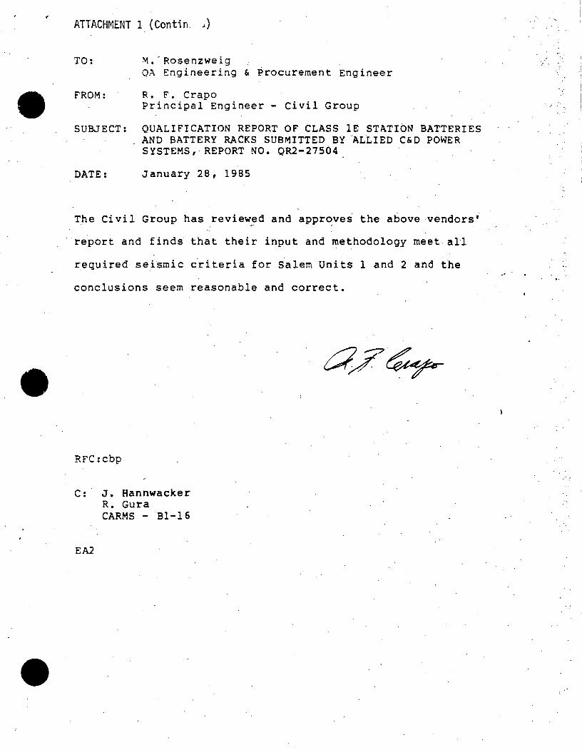
•
ATTACHMENT 1 (Contin. ,)
TO: ~.-Rosenzweig
QA Engineering & Procurement Engineer
FROM: R. F. Crapo Principal Engineer - Civil Group
SUBJECT: QUALIFICATION REPORT OF CLASS lE STATION BATTERIES AND BATTERY RACKS SUBMITTED BY ALLIED C&D POWER SYSTEMS, REPORT NO. QR2-27504
DATE:. January 28, 1985
The Civil Group has review:d and appr~ves the above vendors'
· report and finds that their input and methodology meet all
required sei~rnic ~riteria for ~alem Units 1 and 2 and the
conclusions seem reasonable and correct.
RFC:cbp
C: J. Hannwacker R. Gura CARMS - Bl-16
EA2
j .
,·",:
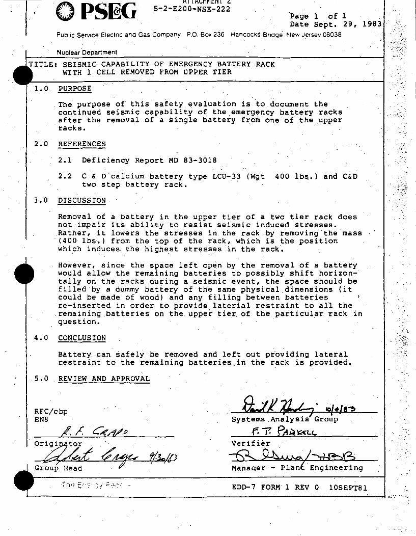
OPS~G· f\I 11"\CHl"ltlIT~-----------~- - - - -
S-2-E200-NSE-222 -Page 1 of 1 Date Sept. 29, 1983
Public Service Electric and Gas Company P.O. Box 236 Hancocks Bridge t-Jew Jersey 08038
Nuclear Department
SEISMIC CAPABILITY OF EMERGENCY BATTERY RACK WITH 1 CELL REMOVED.FROM UPPER TIER
1. 0 - PURPOSE
The purpose ~f this.safety evaluation is to.document the continued seismic capability of the ~mergency batt~ry .racks after the removal of a single battery from one of the _upper
· racks.
2.0 REFERENCES
2.1 Deficiency Report MD 83-3018
2.2 C & D calcium battery type LCU-33 (Wgt 400 lbs.} and C&D two step battery rack. ·
3.0 DISCUS8ION
Removal of a battery in the upper tier of a two tier rack does not impair its ability to resist seismic i ndu.ced stresses. Rather, it lowers the stresses in the rack by removing the mass
· (400 lbs~) from the top of the r~ck, which is t~e position which induces the highest str~sses in the rack~
Howe~er, since the space left op~n by the removal of a battery would allow the remaining batteries to possibly shift horizon-· tally on the racks during a seismic event, ~he space should be filled by a dummy battery of the same physical dimensions (it could be made of wood) and any filling between b~tteries re-insert~d in order to provide laterial restraint to all the remaining .batteries on the upper tie~ of the particular rack in question. ·
4.0 CONCLUSION
Battery can safely be rem.oved and left out pr·oviding lateral restraint to the remairiing batteries in the rack is provided •
. 5.0. REVIEW AND APPROVAL
RFC/cbp EN8
o~~ Group Head ~
·.· [}.Jf :V,.L ? . IO/t/t'!> Systems .Analysis Group .
.f.. 7- PA~ ~<Lt.. Verifier
--£?.,.~~
EDD-7 FORM 1 REV 0 lOSEPTBl
,,·· : ..• ·,
______ .:..._,. _______________________________ ....,.-,.1 ,;·.·
'. ;'.
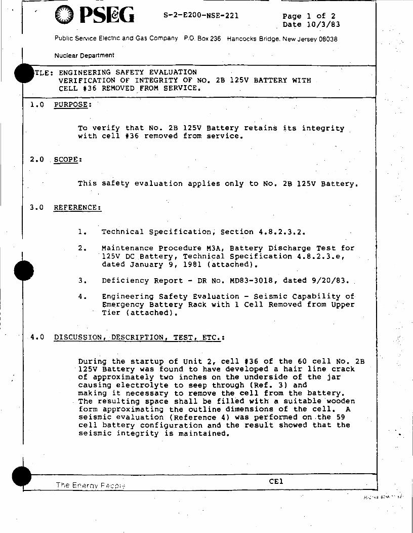
OPS~G S-2-E200-NSE-221 Page 1 of 2 Date 10/3/83
Public Service Electric and Gas Company P.O. Box 236 Ha.ncocks Bridge. New Jersey .08038
Nuclear Department
TLE: ENGINEERING SAFETY EVALUATION VERIFICATION OF INTEGRITY OF NO. 2B 125V BATTERY WITH CELL #36 REMOVED FROM SERVICE.
1. 0 PURPOSE: .
To verify that No. 2B 125V Battery retains its integrity with cell #36 removed from service.
2.0 . SCOPE:
This safety evaluation applies only to No. 2B 125V Battery.
3.0 REFERENCE:
1. Technical Specification~ section 4.~.2.3.2.
2. Maintenance Procedure M3A, Battery Discharge Test for · 125V DC.Battery, Technical Specification 4.8.2.3.e, dated January 9, 1981 (attached).
3. Deficiency Report - DR No. MD83-3018, dated 9/20/83.
4. Engineering Safety Evaluation - Seismic Capability of· Emergency Battery Rack with 1 Cell Removed from Upper Tier (attached).
4.0 DISCUSSION, DESCRIPTION, TEST, ETC.:
During the startup of Unit 2, cell 136 of the 60 cell No. 2B ·12sv Battery was found to have developed a hair line crack of approximately two inches on the underside of the jar causing electrolyte to seep through (Ref. 3) and making it necessary to remove the cell from the battery. The resulting space shall be f ill~d with a suitable ·wooden form approximating the outline dimensions of the cell. A seismic evaluation (Reference 4) was performed on .the 59 cell battery configuration and the result showed that the seismic integrity is maintained.
CEl
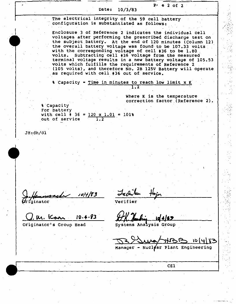
t'\l,,fll'IL.11 I J \~rrruc:u I
~ p;. e 2 Of 2 Date: 10/3/83
The electrical integrity of the- 59 cell battery _, configuration is substantiated as follows:
Enclosure 3 of Reference 2 indicates the individual cell voltages after performing the prescribed discharge test on the subject battery.- At the end of 120 minutes (Column 12) the overall battery voltage was found to be 107 .33 voits: . with the corresponding volta_ge of cell t36 to be 1. 80 . volts. Subtracting cell 136 voltage from .the measured· terminal voltage results in a new· battery voltage of 105.53 volts which fulfills the requirements of Ref~rence 2 (105 volts), and therefore No. 2B 125V Battery will operate as required with cell. 136 out of service.
% Capacity = Time in minutes to reach low limit x K-1. 2
Where K ii the temperature cori~ction factor (Reference 2).
% Capacity For battery with cell i 36 = 120 x 1.01 = 101% out of service 1.2
JH:dh/dl
Verifier
o.'"· l~ 10.+·Vl O~iginator's Group Head
CEl
',.·-:
: ·:-,
. - .. ~ .
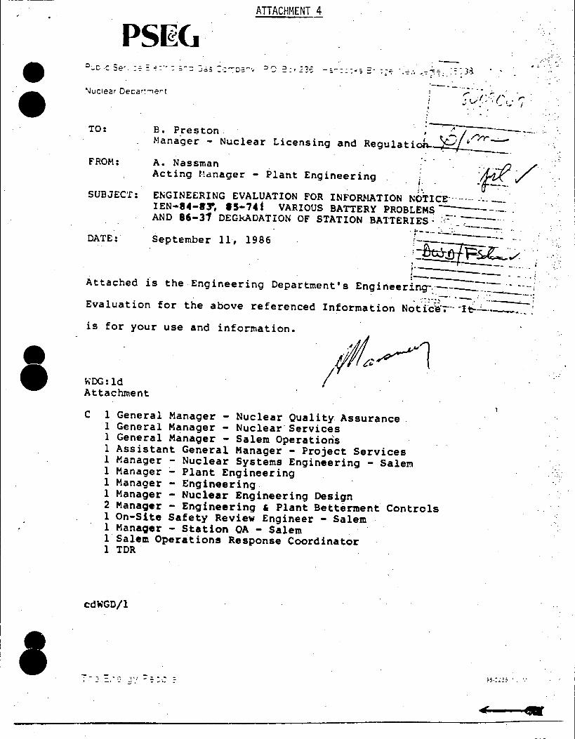
• •
I
I
. -ATTACHMENT 4
PS~C. -~ .. _, .. ·
'\Juc!ear Decar'.-iert ·---- .. ,.. . ··-(" ·,..
',_,..(, ', I .. .,; • - ., I
TO: . =~--------B. P_reston. ; ---10/~/"/'Y"~ -~---Manager - Nuclear Licensing and Regulation... . . · . __ _
FROM: A. Nassman Acting ~dnager - Plant Engineering ~fif/ ENGINEERING EVALUATION FOR INFORHATION Nb.TICE···-- .... -·-. --IEN-84-1'9, 15-74 f VARIOUS BATTERY PROBLEMS-·---AND. 86-31 DEGkADATION OF STATION BA'I'TERIES ~ :.:-=-~- ---.. ·
... -···-·--.
;.
SUBJECT:
DATE: September 11, 1986 't;---·- -·-.. ~----~-
!~!if?~./. :; ...• [:__ -- ~-~·-_,
Eng i rieering-:·--:--~-~~------·· Attached is the Engineering Department's .... ·.-~.;--· .. -- :
Evaluation for the above referenced Information Nc;;t-fc~·;-·· -1~-=--·--···- .' is for your use and information •
WDG: ld Attachment
. flt.~ I . .
C 1 General Manager - Nuclear Quality Assurance 1 General Manager - Nuclear· services 1 General Manager - Salem Operations 1 Assistant General Manager - Project Services l Manager - Nuclear Systems Engineering - Salem 1 Manager Plant Engineering l Manager - Engineering l Manager - Nuclear Engineering Design 2 Manager - Engineering ' Plant Betterment Controls l On-Site Safety Review Engineer - Salem 1 Manager - Station OA - Salem l Salem Operations Response Coordinator l TOR.
cdWGD/l
;;.:.:;: . . . .
' -
···::
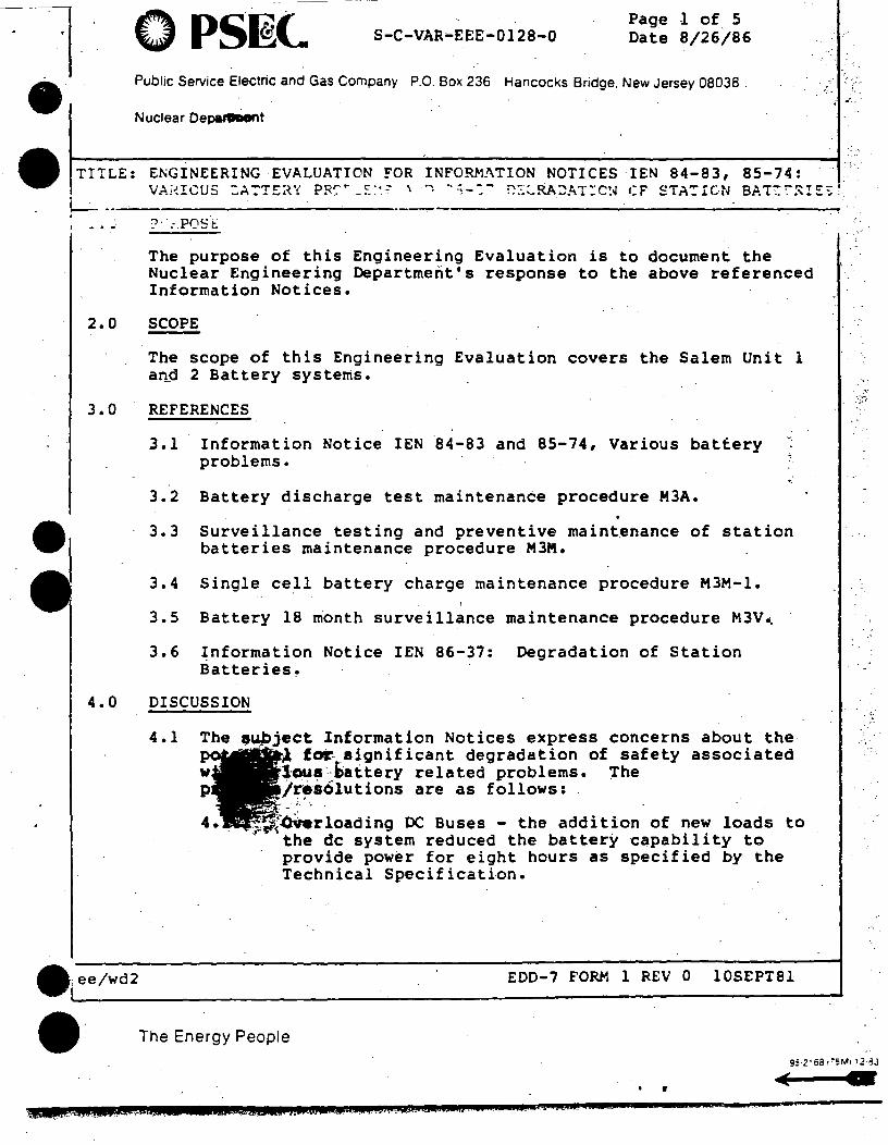
•
0 PS~C. S-C-VAR•EEE-0128-0 Page 1 of 5 Date 8/26/86
Public Service Electric and Gas Company P.O. Box 236 Hancocks Bridge. New Jersey 08038 .
Nuclear OepaJODent
TITLE: E~GINEERING ·EVALUATION _FOR INFORMATION NOTICES IEN 84-83, 85-74: VAiHCUS
L- -----------------: -·" :>··.-Po~·t.:
The purpose of this Engineering Evaluation is to document the Nuclear Engineering Department's response to the above referenced Information Notices.
2.0 SCOPE
The scope of this Engineering Evaluation covers the Salem Unit l a~d 2 Battery systems.
3.0 REFERENCES
3.1 Information Notice IEN l4-83 and 85-74, Various battery problems.
3.2 Battery discharge test maintenance procedure M3A.
3.3 Surveillance testing and preventive maint~nance of station batteries maintenance procedure M3M.
3~4 Single cell battery charge maintenance procedure M3M-l.
3. 5 Battery 18 month surveillance maintenance procedure M3V •.
3.6 Information Notice IEN 86-37: Degradation of Station Batteries.
4.0 DISCUSSION
4.1 The f~ject Information Notices express concerns about the ~ for- aignif icant degradation of safety associated
w 1C)U~·-i>attery related problems. The p /r~solutions are as follows: . .
.;. ·.
· ~~~rloading DC Buses - the addition of new loads to ~ the de system reduced the batter~ capability to
provide power for eight hours as specified by the Technical Specification •
• ee/wd2 EDD-7 FORM 1 REV 0 10SEPT81
• The Energy People
".--
·.·:,.
95·2'68 1'5M1 '.2·~J
~ . QQAIL.4MOW>!!iiU.& &!Cbb!U J..W&SIQ.l i.W#W.A¥AiS#t£AtJCMJ!tJ4P .t_ a.z.:c .A.At neaeu m =- x .....
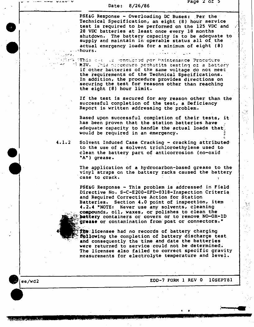
• •
..... - .. --- ..,.,..v-...,,
. ",. ., .
Date: 8/26/86 Page 2 of 5
PSE&G Response - Overloading DC Buses: _Per the Technical Specification, an eight (8) hou~ service test is required to be performed on the 125 VDC and 28 voe batteries at· least once every 18 months shutdown. The battery capacity is to be adequate to supply and maintain in operable statu~ all of the actual emergency loads for a minimum of eight (8)
. ~hours •
··, __ ·-::···:.···Thi.:.:·:--: ,::: ·-=·~~~.:::-~d rcr- ~'7-!.ir.tenar,ce ?roc~".!·...:re ·· .,.,. r-!3V ... -~i:.: -~:.-:-.cc~:·..1ro ~,r-~hlt:its testi.n1. o~ a tat~'=!C"'l
if other batteries of the same voltage do not meet the requirements of the Technical Specifications. In addition,_ the procedure provides directions on securing the test for reasons other than re~ching the eight (8) hour limit.
4 .1. 2
If .the test is secured for any reason other than the successful completion of the test, a· Deficiency Report is written addressing the problem.
Based upon successful completion of their tests, it has been proven that the station batteries have : ~dequate capacity to handle the actual loads that~ would be required in an emergency. ~
....
Solvent Induced Case Cracking - cracking attributed· to the use of a solvent trichloroethylene used to clean the battery part of anticorrosion (.no-oxid "A") grease.
The application of a hydrocarbon-based grease to the vinyl straps on the battery racks caused the battery
· case to crack.
PSE'G Response - This problem is addressed in Field Directive No. S-C-E200-EFD-0318-Inspection Criteria and Required Corrective A~tion for Station Batteries. Section 4.0 point of inspection, item 4.2.4 "NOTE: Never use any solvents, cleaning
···~:-~ compounds, oil, waxes, or polishes_ to clean the · ··'~;~:~.-ttery containers or covers or to remove_ NO-OX-ID
"~--gr•••• or contamination from post or con~ectors. •
-~,.~ .. :licensee had no reco~ds of. battery charging :~ftOllowing the completion of battery discharge test
'':'·_.· ··arid consequently the time and date the batteries were returned to service -could n~t be determined .• The licensee also failed to cQrrec~ specific gravity measurements for electrolyte temperature and level.
EDD-7 FORM l REV 0 l0SEPT81
'
. ".-··
-,.'
; ·.
. '· ..
~· ~ • - 1.. ·~~:, ~ ; ' • .. - .. • ~ _;\....... • J ·- ~ •• •
~·- : t ' ,,. - • - • • ' ., ._ $.JJi##W au.a &&
•
• •
S-C-VAR-EEE-0128-0 Page- 3 of 5
ee/wd2
4 .i. 4
4.1.5
4.1.6
Da -ce: 8/26/86
PSE&G Response - Maintenance procedure M3V-Battery 18 month surveillance has sign-off blocks for all crit~cal steps1 the date and time are also procedure requirements. The procedure corrects for specific gravity, temperature and electrolyte levels as ~equired.
The licensee had no written·procedures for condu~tino charges ·ot_· the .stati•;n '":.::tterit:-s. . ;
_PSE&G Response ..; t1ainten3nce r,r~·-:-:'._'.t:~·~ ~! :::-l-Single Cell Battery Charc;e addresses tb:: cl1arr,,; iny of a single cell (28, 125, and 250Vt battery.
The battery performance discharge test was performed improperly because the test was stopped before reaching the minimum specified voltage.
PSE&G Response -·Battery Discharge Test procedure M3A eliminates the possibility of this occurring. Item 9.2._6 states that •The discharge is to be maintained until one of the following limits is reached:
Low Cell Voltage - 1.25 VDC
Low Battery Voltage
28V 22.8v
125V . 'IO'SV
250V 2lOV
-.
It also notes th~ following, •the discharge is to be stopped immediately when the limiting voltage is reached•. ~
The procedure has sign-off blocks for these steps.
There were no station procedures for maintaining station batteries .in ac~ordance with the battery_ ~endor's manual or IEEE Std. 450-1975 •
•
- · PSE'G Response - All the aforementioned. procedures ::Are utilized to maintain the station batteries1 the ~PJ::pc•~ures were developed from manufacturers -~t'ion manual and IEEE standard 450-1975 · ~~'irements. · . ~ ·. .
. . - -
4.1.7 The intercell resistance values of the batteries were not compared with the previous values to determine when corrective ac~ion was required.
EDD-7. FORM-1 REV 0 10SEPT81
r
-· . ·.
·I --',· ·: __ ,
· .. ·. ';,
-. r-~-m.--~wuuu-u - -- -Page 4of s Date: - B/26/86
PSE&G Response - Battery 18 month surveillance procedure - M3V requires cell to ~ell and termin•l connection resistance to be recorded. The ,, •
•
• •
• _ ee/wd2
•
4.1.8
resistance values must be less than or equal to the established acceptance criteria_ of .01 ohms •
The licensee did.not always conduct equalizing charges when requiied; nor did the licensee have
. pz;oc&<hn.·-:; f·..i~ :....o:-. ·:··.cir.; ~.:-.-::: nrc·~re,:;s of .·rn . . . ' . . ' equ:il·1z ~ r· . . ;t'=ll,"'~C.. ..... -~et,_:rr:-..... ntnc; ·.;pi:.-: ta-le Cl.Li.::~~
should b~ terniJ.na~·::i,:.
PSE&G Response ~ The weekly preventive maintenance and surveillance requirements of maintenance procedures M3M and the 18 month surveiilance procedure M3V assure that the batteries are adequately charged. If a battery cell requires charging maintenance procedure M3M-l will be
/·
invokedt this procedure monitors the progress of the_ charge and determines when the charge is sufficient.
4.1.9 · Surveillance procedtires for the 60-month rated-capacity discharge test did not conform to _ IEEE std. 450-1975 because the test was terminatel at the end of 8 hours, instead of when the terminal voltage fell- to the minimum specified value (usually 1.75 volts per cell).
PSE&G Response - Same response as item 4.1.5 •
4.1.10 The licensee's procedures did not require that the average specific gravity -t>e calculated and compared· to the technical.specification acceptance criteria.
PSE&G Response - Maintenance Procedure M3M • (Reference No. 3.3) requires that the Technical Specification acceptance criteria be met; the requirements are incorporated into the· procedure as surveillance requirements.
4.1.11 The battery capacity tests required by the Final
•--f-8~,Analysis Report (FSAR) and IEEE Std. 450-1980 ~re not performed • •
: PsE5G .Response - The battery capacity test ---requirement is covered in maintenance procedure
· MJA-Battery Discharge Test.
4.1.12 The pilot cells were not being changed on a yearly basis, as recommended by the vendor's technical instructions •
EDD-7 FORM 1 REV 0 10SEPT81
I r • :- -: :...·~;· '.;t.i.~. :::-~ •• • •. !"' ... i" \ ; . . .• .J. •• ••• ••• ,, •• .' .. ; .. • •... • • ~.. • • -.. •
----- - ------
~ s-c-VAR-EEE;;.~---icr~v Date: 8/26/86
Page 5 of 5
I •
4.1.13
PSE&G Response - Pilot cell maintenance is covered in our surveillance testing and preventive .
·maintenance (M3M) procedure. ·The procedure details -"/ weekly and quarterly preventive maintenance and surveiliance.
The station engineer responsible for the technical aspects ~f battery operation, maintenance, and surveill~~c~ did not receive s~~voillance results and aata s11€€ts on a routine ·~asi:;. ·
PSE&G Response - The PSE&G maintenance department retain files on all battery test and inspections.
4.1.14 Station batteries exhibited flaking of the cell plates and flaking of the plate's hook area where the plates connect to the cell posts.
5.0 CONCLUSION
PSE&G Response - This pr6blem is addressed in Field . Directive No. S-C-E200~EFD-0318 Inspection Criteria
and Required Corrective.Action for Station Batteries, Section 4, Item 4.2.7 addresses this problem. •The cell shall be.checked for flaking · positive plates and straps.~.The cell .shall be ~ inspected to determine if any flaking has bridge~ the plates.•
The aforementioned battery maintenance procedures provide the guideline for surveillance, testing, and preventive maintenance of station batteries. These maintenance procediires eliminate the occurrence of the outlined problems.
There is no action required.
6.0 SIGNATURES
Date
Mil'nager - Date Plant Engineering
'Date
• ee/wd2 EDD-7 FORM 1 REV 0 10SEPT81
• r
wwwsu.ma .x-:ac um;;ww.aezau:m w.ewww c
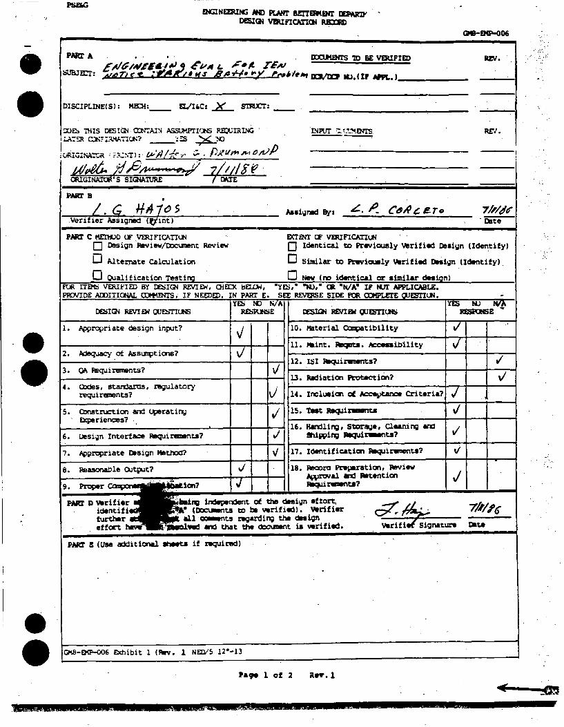
.,
• •
-·
•
EH:ilNEEW«i NI> PLAHr BmfHUHl' miM'D' • DESI~ VrJUFICATUJi RilXR)
DISCIPLINE( SI: MECi:__ fl./U,C1 _){__ S'm.CT:
!X)~ nus DES!Ql· a:NrAI:-l ~.PTI'.N; RE:CIRING . tr.A:~ C.l·ff:~"\A7!CI'? !~ ~:-0
l<.iRIGINA.."':.R '::C:<.:~.-r>:· ;:;:;;:;~~· ~. /)£lll""~rD/f/j) /;(/~ l/_.fi/i,. '·~· '!./ CIUGINA'.Iat S SI~lURE 7/r:J/St?
PllRr B ' L.G H1tzos ' Aaai~rwd Bya 4C.. ~
.Verifier Assigned <t,tintl
PNC! C l'lEnlX> t:E VDUFICATI<.:N EXTENI' CF VEJUFICATI<.:N
RE\1 •
REI.
CdA~ l!To 7/,/tl~ - Date
O Design ·ieview/D:lclnent Review O Identica.l to Pr .... icusly Verified Dlt•i~n (Identify)
D Altei::nate ca1cu1ation D !:iimilar to ~ia.ly 'Jlarified DHieJn (Identify).
0 Qualification Testin:i 0 Nev (no identic:&l or: aimilar deaianl EU\ IT~ VEl\H:IED BY l:ESI~ REVIE:W, O!EIJ< l:IEU.lol, •ye:;,• "Ml,• CR •NJ A• IP N.7I' APPLICABLE. PIU.'IDE AOOITIOOAL QMo\mI"S, IF NEEDED, IN PART E. SEE ~£ SIDE ~ a::K'IZI'E Cl.JESTI<.:N. -
y~ !'Cl N/A ~ NJ NI/. DE:SI~ Rf.VI &l ClJ~TitM; ~E CES!Gi REVI&oi tlJESTI<Jti ~E ..
1. .Appropriate design input? 10. Material ~tibility ./ .. ..;
11. Maint. ~. Acceaibility v J 2. AdeqUacy of Ass~tions?
rl 12. ~I Rlq.lir.-nts? 3. °"' Requi niments? v
13. Jgdiation Protection? .j 4. Cl:Jdes, standa.ra5, 1119Ulatory '
requiranents? J 14. Inell.Wion cf ~ Criteria? / s. COnstruc:tiai and ~ratil"l,I .; 15. Tat 118cpi~ .J
EXperienc:eS? .. 16. ficyjling , Stor8,1•, ClMni ng Wa:1
6. Uesi~n Interface Requi remmts? ,j !hi5'1Ping Jllaqu.i~ta? ./
7. Appropriate Dnign Method'? " i7. Identification ~irwaenta? ti
e. Psuonable OJtpit? .j 18. Rea:>ro Preparatiai, Raviw j AWroval ~ Attentiat
··- ••• .J --· P11Rf D 'Jlarifier ·. ng iudepeudent of the desi<Jn eftort, . identifi • (~ts to t» wrifiedl. 'Jlarifier ~~ 7/1/,~
f\&r'th9r · · au ~ts nigardil'Q the dai;n effort h99W · Rd ~ that the ~t ia wrifi.S. var~f~natun Cate
PNC! I (USe additiaial ahMt.a if RQUiredl
~-EXP-006 Exhibit l (Rlrv. 1 NEIV5 i2•-13
Pa99 l of 2 Rn'. l
. : ..
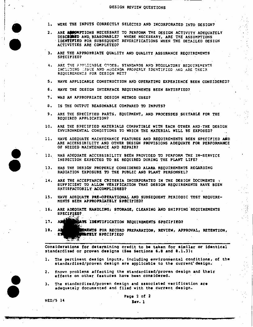
. t
.,
• •
•
•
1 •
2.
3.
4.
DESIGN REVIEW QUESTIONS
WERE THE INPUTS CORRECTLY SELECTED ,AND INCORPORATED INTO DESIGN?
ARE AtM.ff'PTIONS NECESSARY DEScaJalD AND. REASONABLE? IDENT!rl!D FOR SUBSEQUENT ACTIVITIES ARE COMPLETED?
TO PERFORM THE DESIGN ACTIVITY ADEQUATELY WHERE NECESSARY, ARE THE ASSUMPTIONS
REVERIFICATIONS WHEN THE DETAILED DESIGN
Alt£ THE .APPROPRIATE QUALITY AND QUALITY ASSURANCE REQUIREMENTS SPECIFIED? .
ARE ~~E ~~?~!:~BLE ~~~ES, STANDA~DS A~O REGULATORY REOUI~EMES~S INC:;;:nNG ::s:.:E .\ND <'LuOC:SCA ?ROPERLY IDEST!Fr:::c .\lliu A.iU: ':'iiE:.R REQUIREMEN73 fOR DESIGN MET?
5. HAVE APPLICABLE CONSTRUCTION AND OPERATING EXPERIENCE BEEN CONSIDERED?
6. HAVE THE DESIGN INTERFACE REQUIREMENTS BEEN SATISFIED?
7~ WAS AN APPROPRIATE DESIGN METHOD USED?
· 8. IS THE OUTPUT REASONABLE COMPARED TO INPUTS?
9. ARE THE SPECIFIED PARTS, EQUIPMENT, AND PROCESS~S SUITABLE FOR THE
10.
11.
12.
13.
14.
REQUIRED APPLICATION?
ARE THE SPECIFIED MATERIALS COMPATIBLE WITH EACH OTHER AND·THE DESIGN ENVIRONMENTAL CONDITIONS TO WHICH THE MATERIAL WILL BE EXPOSED?
HAVE ADEQUATE MAINTENANCE FEATURES AND REQUIREMENTS BEEN SPECIFIED AilD ARE ACCESS IBIL"ITY AND OTHER DESIGN PROVISIONS ADEQUATE FOR PERFORMANCE OF NEEDED MAINTENANCE AND REPAIR? .
HAS ADEQUATE ACCESSIBILITY BEEN PROVIDED TO PERFORM THE IN-SERVICE INSPECTION EXPECTED TO BE REQUIRED DURING THE PLANT LIFE?
HAS TH! DESIGN PROPERLY CONSIDERED AI.ARA REQUIREMENTS REGARDING RADIATION EXPOSURE TO THE PUBL,IC AND PLANT PERSONNEL?
ARE THE ACCEPTANCE CRITERIA INCORPORATED IN THE DESIGN boCUMENTS \ SUFFICIENT TO ALLOW VERIFICATION THAT DESIGN REQUIREMENTS HAVE BEEN SATISFACTORILY· ACCOMPLISHED?
15. RAVE ADEQUATE PU-OPERATIONAL AND SUBSEQUENT PERIODIC TEST REQUIREMENTS BE!N APPROPRIATELY SPECIFIED?
16. ARE ADEQUATE HAllDLillG; STOit.AG!, CLEANING AND SHIPPING REOUIREMENTS SP!CirlG? .. ~ · .. ~ . . ._·· ~ .. ~ ..
17. REQUIREMENTS SPECIFI!D?
18. PREPARATION, REVIEW, APPROVAL, RETENTION,
Conaideration1 for determininQ credit to be taken for similar or identical standardized or proven d••ions (See Sections 6.8 and 8.1.3)1
1. The pertinent des ion inputs, includinQ environmental conditions, of the standardized/proven desion are applicable to the current"desi;n.
2. Known problems affectino the standardized/proven design and lheir effects on other features have been considered. ·
3. The standardized/proven design and associated verification are adequately documented and filed vith the current d•sion.
NED/S 14 Page 2 of 2
bv. 1
•t..z;;sc;:azett§.- [a ¥442-W ¥.Ak.CJ.#SWWW•4;µ 42W#lA. .... 1 au IM41A.CZA%. (#GS ¥ . UkU
. ;·
..
.. ')-'
• •••
•
•
'TO:
FROM:
... ···-····-=··· \----··-···---,-
PUBLIC SERVICE ELECTRIC AND GAS COMPANY NUCLEAR DEPARTMENT
DATE: April 13, 1983 RESPONSE DUE: N/A
E •· A. Liden Manager - Nuclear Licensing and ·Regulation
L. A. Reiter Manager - Nuclear Systems Engineering
SUBJECT: NRC INFORMATION NOTICE•J-11' POSSIBL°E SEISMIC VULNERABILITY OF OLD LEAD STORAGE BATTERIES
Discussion: . .
As s_ummarized in the above Information Notice, no seismically induced battery failure has occurred to date. The NRC is considering research that will define the seriousness of age related seismic vulnerability of lead storage batteries •
A~ this time, sufficient information is not available to determine either the seriousness of battery seismic vulnerability or a course of corrective action and/or plant specific pattery vulnerability evaluation processes. · Further regulatory guidance on the issue is required. ~
A copy of this notice is being forwarded to Plant Engineering for information.
t!i 'I' REF:tap
CC: R. L. Gura A. Korn
ffiioli{;.l:t:1 N:JCi.C:i\i\ UtE~!~-lNil
At;'; n:c.m.A TIOH \ E. \
D. K. Harding tiDTED ••••. u.
SAG Fi le - IE Not ices
GM7 l
---~~T'-;, ..
BY. ___ ~--
~-. '· . .,·~· ' _ • .......... ~· ~·-' ,.,.·.,...,.,....,_.· ·~·. ',.•..,,,·, \.-· . ·. ·. ·.·.r_ ,_._."'ti.,,,..,.....·, •. -•'J., __ .~· . @4.2@CJ$£2EWWUA2@1#.QA. _i · · IM!M.£1.~.AWJWU? .. -''8!<!h'*
-: J
\ i
••
•
..
•
Iii 11\CiiilChi 1 \GOllClliUCCI)
0.PSbG L••'·:;,•
Public Ser•,•ce !:'.::c:~:c and Gas Company P.O. Box E . . . . .MAN.tGER /',:,' .. \1 Hancocks 8r:dge, Ne·11 Jers y 080.UCLEA~ LICENSIN; . ':~.<:. ·
Salem Generating Station April 8, 1983
. ANJ REGULATION . ·'./'.'.f E. A. LIDEN .: ... ·,
NOTE> ••• · ••• ••••••••• ••. · ..... :.-.~] ~.' 1 5 1983 .· . ·4 .
llRa TO .............. ; ...... , .... ,
.. =~-~·.·.:·.:::~:::::::::::::·· \, To the Manager - Nuclear Licensing and Review Fl . .J .1, ~ .. ' .. ·• . .. :
IE NOTICE 83-11, POSSIBLE SEISMIC VULNERABILITY OF OLD LEAD STORAGE BATTERIES
The Maintenance Department performs inspecti_ori .of batt~ries in accordance· with the·. following schedule.
60 month
18 month
18 month
18 month
90 day
7 day
Test discharge of 28V - 12SV batteries
Test discharge of 2SOV batteries
Visual inspection of plates - ali cells 28V, l25V and 2SOV
8 hour connected load service test -28V and l25V
Test all cells 28V, 12SV and 250V batteries
Test of pilot cells only 28V, 12SV and 2SOV batteries
There have been no failures attributable to the causes· identified in this IE Notice, however, we have.changed cells due to individual cell.voltage and specific gravity problems.
No. 2 2SOV battery presently has a cell jlimpered out due to low individual cell voltage. ·
Maintenance Procedure M3-M specifica·11y states that a visualinspection for any abnormalities and·deterior~tion shall be performed in accordance with the above· schedule of inspections.
KW:kls
The Energy People
General Manager -Salem.Operations
·,.,_
.. , ·,
, .. ·.;.·.
. t za . U : l!U.% £$. UUCl.J 3&&.4AMJ¥J &. 0 k. ... £J :au .z..u ; #EA ... a . Ii :za k
-,
'
en 111 -t .z en )> m > -t :0 r - )> m 0 -t s: z -z . G>
TULi 1-10 llDllJIV.u.IllD IATll Tlllll I ~ . ·IDUU c-:a
I :c w
m lDLJIU IPICinCATicm• nlQUDIC?
6.0 - 1.0 2/V pll
Uc1Uo1. . == UcaUoa. ,.. n :t .ti: -f: rn en ,..
H~ -I n ~ irn 'U
..;) I:'" :z:I tiJ ~H tc:atioa. :z: t< :z: -< ..;) Cil
10.1 11S/c:11 2/V
1100 ppb 2/V
1150 JPll 2/V
!5 ppb 2/V
.!,10 ppb Vbea•Hr Cl HCHdl li•it
Spec Cood
02
Cl
•• r
Ve1tia~bou1e Speci
V11tingbou1e Specif
irn -ic:atiOD. t-A 'U irn :z: tsJ n - n:c en ic1tion. n H ll1 0 "IJ tJ
icatioa. :i H C: ...... rt" 01:'" .... > ll1 ::z:J ic1tioa. :i ..;) r: ~t c:
ic:11Uo1. fl c-, Clo :z: tJ - rn ic:ation. -t
.110 ppb 2/V
120 ppb 1/11
.!,5 ppb I/If
!5 ppb 1/11
.!,100 ppb I/I
,!50 ppb l/V
Si02
&l
Ca
Ilg
TOC
Suap Solidi
V11tingho~•• Specif
Ve•tingbouae Sp•cif
Ve1tiaghou1• Specif
Ve1ti1ghou11 Specif
Ve1tiagbou1e Specif
V11tiagbou11 Specif -Tritium •• l•q'cl C) :z
TULi 1-11 ,CITIOI ID IULUlllT :a -a l.lllllU
rn > -= m IPICIFICATIOlll IJl&LISU - m n en - :c 1/0 Ca.poatte '•11dor IHlrail. Cl I z t..> "" CID . ·c1-J111
CID ...... • 0
.. = ....... ' .,, 0
l.o