Embed Size (px)
Citation preview

Handbook for approval assessment of transport braking
systems on free-steered vehicles in underground coal mines
MDG 39
Produced by Mine Safety Operations Division,
New South Wales Department of Primary Industries
February 2001
NSW Department of Primary Industries 516 High St, Maitland NSW 2320
(PO Box 344, Hunter Region Mail Centre 2310)
Fax: (02) 4931 6790 Phone: (02) 4931 6632
Website: www.dpi.nsw.gov.au/minerals/safety

Handbook for approval assessment of transport braking systems
PUBLISHED: FEBRUARY 2001 DISCLAIMER The compilation of information contained in this document relies upon material and data derived from a number of third party sources and is intended as a guide only in devising risk and safety management systems for the working of mines and is not designed to replace or be used instead of an appropriately designed safety management plan for each individual mine. Users should rely on their own advice, skills and experience in applying risk and safety management systems in individual workplaces. Use of this document does not relieve the user (or a person on whose behalf it is used) of any obligation or duty that might arise under any legislation (including the Occupational Health & Safety Act 2000, any other Act containing requirements relating to mine safety and any regulations and rules under those Acts) covering the activities to which this document has been or is to be applied. The information in this document is provided voluntarily and for information purposes only. The New South Wales Government does not guarantee that the information is complete, current or correct and accepts no responsibility for unsuitable or inaccurate material that may be encountered. Unless otherwise stated, the authorised version of all reports, guides, data and other information should be sourced from official printed versions of the agency directly. Neither the Department of Primary Industries, the New South Wales Government, nor any employee or agent of the Department, nor any author of or contributor to this document produced by the Department shall be responsible or liable for any loss, damage, personal injury or death howsoever caused. Users should always verify historical material by making and relying upon their own separate inquiries prior to making any important decisions or taking any action on the basis of this information. © Copyright NSW Department of Primary Industries This work is copyright. Apart from any use as permitted under the Copyright Act 1968, no part may be reproduced by any process without prior written permission from the NSW Government. Requests and enquiries concerning reproduction and rights should be sent to the Director of Mine Safety Operations, NSW Department of Primary Industries.

Handbook for approval assessment of transport braking systems
HANDBOOK – Design, Approval & Maintenance of Braking Systems [Feb 2001] Page 3 of 52
PREFACE This Handbook is primarily intended for the use of Officers of the Department of Mineral Resources and Assessors involved in the approval of Transport Braking Systems. The information contained within the handbook is also a valuable tool for manufacturers, service/maintenance organisations, users and others concerned with the safe operation of Transport Braking Systems on free-steered vehicles when operated in underground coal mines. All mineworkers rely on free-steered, diesel powered, vehicles for safe transport to and from the workplace and for their day to day work underground. The proper design, testing and maintenance of braking systems on these vehicles is essential to minimise the risk of injury to all mineworkers. The Handbook has been prepared to assist in maintaining the safety of personnel and vehicles. The Handbook specifies the requirements for the design, installation, testing and maintenance of braking systems fitted to free-steered vehicles in underground coal mines for the purposes of approval assessment. Note In New South Wales, braking systems are required to be approved under the
requirements of clause 61(1)(b) of the Coal Mines (Underground) Regulation 1999. This Handbook will assist in the processes of approval.

Handbook for approval assessment of transport braking systems
HANDBOOK – Design, Approval & Maintenance of Braking Systems [Feb 2001] Page 4 of 52
CONTENTS PREFACE FORWARD SECTION 1 DESIGN AND CONSTRUCTION 1.1.0 SCOPE 1.2.0 REFERENCED DOCUMENTS 1.3.0 DEFINITIONS 1.4.0 DESIGN 1.5.0 SERVICE BRAKES 1.6.0 SECONDARY BRAKES 1.7.0 PARKING BRAKES 1.8.0 AUTOMATIC BRAKES SECTION 2. MARKING 2.1 PLATES & LABELS 2.2 COMPLIANCE PLATE 2.3 SPECIFICATION PLATE 2.4 WARNINGS SECTION 3. TESTING 3.1 TYPE TESTING 3.2 MODIFIED COMPONENTS 3.3 ROUTINE TESTING 3.4 IN-SERVICE TESTING SECTION 4 DOCUMENTATION 4.1 GENERAL 4.2 MANUFACTURER - Testing authority 4.3 TESTING AUTHORITY - Manufacturer 4.4 MANUFACTURER - Purchaser 4.5 MANUFACTURER - Statutory authority

Handbook for approval assessment of transport braking systems
HANDBOOK – Design, Approval & Maintenance of Braking Systems [Feb 2001] Page 5 of 52
APPENDICES A MEANS FOR DEMONSTRATING CONTINUED COMPLIANCE WITH THIS
HANDBOOK (normative) B TEST CONDITIONS (normative) C TYPE TESTING - Brake Performance (normative) D TYPE TESTING - Brake temperatures and fade (normative) E ROUTINE TESTING (normative) F IN-SERVICE TESTING (informative) G SPECIFICATION OF INSTRUMENTS (normative) H DOCUMENTS REFERRED TO (informative)

Handbook for approval assessment of transport braking systems
HANDBOOK – Design, Approval & Maintenance of Braking Systems [Feb 2001] Page 6 of 52
FOREWORD Various Australian Standards and the relevant statutory requirements lay down standard criteria for the design and performance of braking systems fitted to on-road and off-road vehicles. This Handbook includes provisions of those Standards and Handbooks and applies them to the underground mining industry. The Handbook is not exhaustive in the coverage of Transport Braking Systems, but is intended to include those areas of concern to achieve a high safety standard. The focus has been placed on performance and design utilising acceptable standards and historical safety information. Manufacturers, Service Organisations and the Users of free-steered vehicles have a 'duty of care' under the provisions of Occupational Health & Safety Legislation to ensure the safe operation of braking systems. The Handbook will assist in meeting those obligations. It is essential for the manufacturer and user that hazards associated with the Transport Braking System be assessed and controlled with appropriate treatments. Risk management techniques shall be employed as per AS4360 “Risk Management”, MDG 1010 “Risk Management Handbook for the Mining Industry” or other appropriate standard. Occupational health and safety aspects shall be considered during this process as per AS4801 “Occupational Health and Safety Management Systems” and the Occupational Health and Safety Act. This Handbook supersedes the provisions of MDG1 and MDG9 in respect of braking systems only. ********************************** ACKNOWLEDGMENT This document was prepared at the request of the Department of Mineral Resources, New South Wales and various stakeholders in the industry. The participation of the members of the editorial committee is noted and appreciated. The edition of the Handbook dated February 2001 is the first edition of this document. As required from time to time the document shall be reviewed to reflect current safety expectations. Comments on any aspect of this Handbook should be submitted in writing to: Gordon Jervis Senior Inspector of Mechanical Engineering NSW Department of Primary Industries 516 High St, Maitland NSW 2320 (PO Box 344, Hunter Region Mail Centre 2310) Fax: (02) 4931 6790 Phone: (02) 4931 6632 Email: [email protected]

Handbook for approval assessment of transport braking systems
HANDBOOK – Design, Approval & Maintenance of Braking Systems [Feb 2001] Page 7 of 52
HANDBOOK FOR THE DESIGN, INSTALLATION, TESTING AND MAINTENANCE OF BRAKING SYSTEMS ON FREE-STEERED VEHICLES IN UNDERGROUND COAL MINES SECTION 1 DESIGN AND CONSTRUCTION 1.1.0 SCOPE This Handbook is produced as an assessment document to assist those persons involved
with Transport Braking System approvals for free steered vehicles pursuant to clause 61 (1)(b) of Coal Mines (Underground) Regulation 1999. This clause states:-
“Transport must not be operated at a mine unless it is approved with respect to its
braking systems.” Note Clause 61 (1)(b) of Coal Mines (Underground Regulation) 1999, employs the
word ‘transport’, see definition at 1.3.8.
As transport braking system can be classified as a safety critical item, any electrical transport braking system shall be designed in accordance with AS/NZS 61508 parts 1,3,4 & 5 “Functional Safety of Electrical / Electronic / Programmable Electronic Safety - Related Systems”.
It would be expected that any assessment carried out for approval purposes would use this document as a compliance document supplying information as detailed in section 4. Documentation providing evidence of OH&S and Electrical obligations shall be provided.
1.2.0 REFERENCED DOCUMENTS The following documents are referenced in this Handbook. MSHA, 30 CFR part 75. Braking Performance - underground vehicles CAN/CSA-M424.3-M90 Braking Performance, Rubber tyred self-propelled
underground mining machinery. AS1180.10B Determination of Combustion Propagation characteristics
of a horizontal oriented specimen of hose using surface ignition.
AS1210 Pressure Vessels AS2660 Hose & hose Assemblies - Air/Water - for Underground
Coal Mines. AS2958.1 Earth Moving Machinery - Safety Part 1 : Wheeled Machines - Brakes AS2971 Serially produced pressure vessels AS3584 Diesel engine systems for underground coal mines. AS3791 Hydraulic hose SAEJ10 Automotive and off-highway air brake reservoir
performance and identification requirements ISO6805 Rubber hose and hose assemblies for underground
mining, wire reinforced types for coal mining - specification.

Handbook for approval assessment of transport braking systems
HANDBOOK – Design, Approval & Maintenance of Braking Systems [Feb 2001] Page 8 of 52
BS7201 Hydraulic accumulators 1.3.0 DEFINITIONS 1.3.1 Vehicle A free-steered vehicle, having a maximum speed of more than 4 km/hr, not operating on
rails, powered by a diesel engine system or batteries and/or electric motors and driven by wheels or tracks, used for the transportation, handling or manipulation of personnel and/or equipment and/or material.
Does not include machines or equipment fitted with tracks or wheels for the purpose of
relocation but which do not perform their normal function while moving.

Handbook for approval assessment of transport braking systems
HANDBOOK – Design, Approval & Maintenance of Braking Systems [Feb 2001] Page 9 of 52
Notes (a) The speed limit is derived from MSHA, 30 CFR part 75. (b) The Statutory Authority may define vehicles requiring approval to this
Handbook in greater detail. (c) Vehicles having a maximum achievable speed of less than 4 km/Hr require
approval in NSW by the Statutory Authority. A risk assessment, based on the applicable clauses of this Handbook is required for any application for the approval of such vehicles.
1.3.2 Brake System
1.3.2.1 Service brakes – (see 1.5) a system used to stop and momentarily hold a vehicle.
1.3.2.2 Secondary brakes – (see 1.6)
a system applied by the operator in the event of a failure of the service brakes.
1.3.2.3 Parking brakes – (see 1.7)
used to prevent movement of a stationary vehicle for prolonged periods.
1.3.2.4 Automatic brakes – (see 1.8)
which apply automatically. (see 1.8.5) 1.3.3 Light metal Aluminium, magnesium, titanium or an alloy containing an aggregate of more than 15%
by mass of aluminium, magnesium and titanium, or an alloy containing an aggregate of more than 6% by mass of magnesium and titanium.
1.3.4 Mean deceleration, (a) Average rate of change of the speed of the vehicle from the instant the brake control
actuation begins until a full stop is achieved. Mean deceleration may be determined from the formula; a = v2 2s where a is the mean deceleration, in metres per second squared; v is the speed of the vehicle immediately prior to the brake control being activated,
in metres per second; s is the stopping distance in metres.

Handbook for approval assessment of transport braking systems
HANDBOOK – Design, Approval & Maintenance of Braking Systems [Feb 2001] Page 10 of 52
1.3.5 Statutory authority The Government department or authority that administers safety and health legislation
pertaining to coal mines within which the approved/certified braking system will operate. 1.3.6 Tare Mass The tare mass of a vehicle including the heaviest combination of cab, canopy and
protective structures (ROPS/FOPS). It also includes components, mountings and equipment which are approved by the vehicle manufacturer, one 85kg operator, full fuel, water, oil and lubricant tanks.
For materials, equipment/stores transporters and LHD's the vehicle shall be fitted with the heaviest combination of attachments recommended by the manufacturer. The attachments shall not be loaded.
For vehicles designed to haul un-braked trailers, the tare mass shall include the unladen mass of the trailer.
1.3.7 Testing authority A body acceptable to the statutory authority to carry out the assessments and tests herein.
(normally a nationally accredited testing authority) Notes (a) Such bodies should be traceable to the Joint Accreditation System of
Australia and New Zealand (JAS-ANZ), which has been established for the purpose of accrediting testing laboratories, to undertake testing. NATA registered laboratories meet this requirement. (b) Approved Competent Persons (Mechanical) may be acceptable Testing
Authorities in New South Wales.
1.3.8 Transport Transport means; a locomotive, rubber tyred or ‘caterpillar’ tracked vehicle (including a shuttle car) propelled by electrical or mechanical means and used for the purpose of transporting persons, materials, coal or stone, whether by carrying, towing or otherwise
Note The following vehicles are required to have approved types of braking systems.
Shuttle car, Hauler-electric (battery), Load-Haul-Dump, Shearer Carrier, Chock Carrier, Personnel Transporter, Grader/Dozer, Skid-Steered Loader.
1.3.9 Vehicle Mass (gross) The operating mass of a vehicle including the heaviest combination of cab, canopy and
protective structures (ROPS/FOPS). It also includes components, mountings and equipment which are approved by the vehicle manufacturer, an 85kg operator, full fuel, water, oil and lubricant tanks.
For personnel carriers, a mass equivalent to the designed maximum number of persons multiplied by 85 kg shall be added.
For materials, equipment/stores transporters and LHD's the vehicle shall be loaded to its' maximum rated payload at the specified axle distribution.
For vehicles designed to haul un-braked trailers, the operating mass shall include the mass of the trailer and the maximum rated load of the trailer.
1.3.10 Normative, Informative Are defined as per Australian Standards.

Handbook for approval assessment of transport braking systems
HANDBOOK – Design, Approval & Maintenance of Braking Systems [Feb 2001] Page 11 of 52

Handbook for approval assessment of transport braking systems
HANDBOOK – Design, Approval & Maintenance of Braking Systems [Feb 2001] Page 12 of 52
1.4.0 DESIGN 1.4.1 General Vehicles shall be fitted with;
a service brake system, complying with Clause 1.5; a secondary brake system, complying with Clause 1.6; a parking brake system, complying with 1.7; and an automatic brake system, complying with 1.8 .
1.4.2 Brake Independence The braking systems shall be sufficiently independent so that failure of one system will
not prevent the operation of the other systems. 1.4.3 No. of wheels braked Vehicles having a designed maximum operating speed of more than 15 kph, when
performing their designed function, shall have the brakes operating on at least four wheels or two tracks for tracked vehicles.
a) For Service Brakes on vehicles which operate at speeds greater than 15 kph
when performing their designed application shall have independent brake assemblies, mechanically connected to and as close as practicable to the wheel hubs or track drive hubs.
b) For Service Brakes on vehicles having a transit speed of more than 15 kph but
which are normally operated at a speed less than 15 kph when being used for their designed application may have a lesser number of brake assemblies providing that the brakes are permanently interconnected through the drive line components including the vehicle transmission or transfer gearbox.
c) For Secondary, Parking and Automatic Brakes, the permanent interconnection
of the brake unit(s) through the drive line components including the vehicle transmission or transfer gearbox, meets this requirement.
1.4.4 Holding ability All brake systems shall be capable of holding the vehicle on a 25% grade in both the
forward and reverse direction with the vehicle loaded to 110% of vehicle mass. or, The manufacturer may instruct the testing authority to test the vehicle on an increased
grade in both the forward and reverse direction with the vehicle loaded to vehicle mass. In addition, the service brake system shall be demonstrated to hold the vehicle on grade
for not less than five minutes, with one application of the brake. or, If the above requirement is impractical for test purposes, then the following alternative
may be employed. Apply a pulling force to the vehicle with the brake set and with the transmission in neutral under test conditions meeting the requirements of Appendix B. The pulling force shall be applied horizontally near to the ground. The force required shall be calculated as follows:

Handbook for approval assessment of transport braking systems
HANDBOOK – Design, Approval & Maintenance of Braking Systems [Feb 2001] Page 13 of 52
F = SIN(Grade) x M x 9.81 where F = pulling force on the machine in Newtons Grade = the maximum operating grade in degrees M = 1.1 X vehicle mass in kg (See 1.3.9) NOTE This test exceeds the requirements of CAN/CSA-M424.3-M90. This Standard is
commonly accepted for metalliferous mining applications in many countries. 1.4.5 Common components The brake systems may include common components provided that the other
requirements for each individual brake contained in this Handbook are satisfied and in the event of the failure of any single component, the braking system shall provide vehicle stopping capacity meeting the requirements of 1.6.4.
1.4.6 Fail to safety At least the automatic and park brake systems shall fail to safety. Brakes applied by
compression springs, on the release of fluid pressure, satisfy this requirement. 1.4.7 Anti-locking All braking systems should be designed to eliminate, or minimise, as far as practicable,
the locking of wheels during brake application. 1.4.8 Stored Pressure Systems Power assisted braking shall be capable of operation in the event of engine failure to
enable the vehicle to be brought safely to rest. For brakes operated by stored pressure systems, the capacity of the stored pressure shall permit at least five applications of the service brakes, after the engine has stopped.
If stored pressure is used to apply the service braking system, then the system shall be
fitted with a warning device that activates before the system pressure drops below the greater of 50% of the manufacturers specified maximum operating pressure level or the pressure required to meet the secondary braking requirements. The warning device shall readily attract the operator's attention by providing a continuous visual and audible warning. Gauges indicating pressure or vacuum do not meet this requirement.
or The automatic brakes shall be applied at the pressure determined to meet the secondary brake performance requirements. (see 1.6.4)
1.4.9 Pressure Gauges Hydraulic or pneumatic, pressure applied, braking systems shall include a pressure gauge
clearly marked to indicate the minimum safe brake operating pressure. The gauge shall be easily visible from the operator's seat.

Handbook for approval assessment of transport braking systems
HANDBOOK – Design, Approval & Maintenance of Braking Systems [Feb 2001] Page 14 of 52
Hydraulic or pneumatic, pressure released (fail-to-safety), braking systems shall include a pressure gauge or a low pressure indicator, clearly marked to indicate the minimum brake release pressure. The gauge or indicator shall be easily visible from the operator's position.
1.4.10 Enclosure Mechanical braking assemblies shall be totally enclosed. NOTE: Liquid cooled brakes are preferred. 1.4.11 Surface Temperatures Mechanical brake assemblies shall be designed to limit surface temperature to a
maximum of 150 degrees Centigrade under conditions of normal duty cycle operation when tested to the requirements of Appendix D.
1.4.12 Wear Indication A clearly identifiable means of monitoring brake wear and the safe adjustment range
should be provided. 1.4.13 Asbestos Brakes shall not include any asbestos material. 1.4.14 Ancillary components Interlocks, valves, logic components, associated mechanical devices shall be engineered,
so as to minimise as far as practicable any accidental application, failure or release of any brake, by reason of system, design or component failure.
Notes (a) Examples of avoidable design or component failure include; The design of door hinges with excessive clearance, where doors are interlocked
to braking systems. (b) The use of pilot operated valves or devices, where direct operated valves are
practicable. 1.4.15 Cables Wire cables shall not be used to apply any part of a braking system. 1.4.16 Fluid Power Systems (a) Accumulators Hydraulic accumulators shall be certified in compliance with Australian Standard
AS1210 or British Standard BS7201. Where a hydraulic system incorporates an accumulator the attachment to the
accumulator shall be by means of a minimal length adaptor and flexible hose. Fittings shall be located or otherwise guarded to provide mechanical protection.
Handbook for approval assessment of transport braking systems
HANDBOOK – Design, Approval & Maintenance of Braking Systems [Feb 2001] Page 15 of 52
A manual bleed valve shall be fitted to allow pressure relief for maintenance.
Fluid should return to tank.

Handbook for approval assessment of transport braking systems
HANDBOOK – Design, Approval & Maintenance of Braking Systems [Feb 2001] Page 16 of 52
Accumulators shall be securely installed.
A guard shall be installed between accumulators and any personnel within a vehicle. The structure of the vehicle may meet this requirement.
(b) Air Compressors Air compressors shall be of a liquid cooled type in accordance with AS3584. (c) Fluid reservoirs Liquid reservoirs shall be fitted with a robust filler cap that is rated for the
maximum pressure in the reservoir system. The cap shall effectively seal the tank from any leakage and be positioned to minimise impact damage in the event of a vehicle collision.
Reservoirs designed to operate at atmospheric pressure may include caps
designed for breathing, provided that they include a labyrinth or similar feature to limit spillage.
Filler caps should be self closing. (d) Hoses Flexible hoses shall be compatible with the fluid used, maximum system pressure
and temperature. The hose factor of safety shall be a minimum of 4 to 1 based on hose burst
pressure to maximum working pressure. Hydraulic hose shall comply with the provisions of AS3791. The requirements
for flame resistance shall be in accordance with testing to AS1180.10B and acceptance to AS2660 or alternately satisfy Schedule 2G of the US Bureau of Mines or comply with type 1 or 3 hose specifications as listed in ISO 6805.
The use of nylon, polyurethane, PVC or similar plastic piping for pneumatic
braking control systems will be acceptable only in cases where loss of pressure within these systems cause the system to fail to safety. All such piping shall be adequately protected and shielded from contact with hot and /or sharp surfaces.
Air hoses shall be in accordance with AS2660 unless specified otherwise. Where hoses are directly attached to a compressor delivery port, they shall be
PTFE, steel wire reinforced, braided construction. (e) Pressure vessels All pressure vessels of capacity greater than 30 litres shall comply with AS1210 -
Unfired Pressure Vessels. Pressure vessels having a capacity of 30 litres or less which do not comply with
AS1210 shall comply with at least one of the following AS2971 Serially Produced Pressure Vessels SAE.J10 Automotive and Off - Highway Air Brake Reservoir

Handbook for approval assessment of transport braking systems
HANDBOOK – Design, Approval & Maintenance of Braking Systems [Feb 2001] Page 17 of 52
Performance and Identification Requirements.

Handbook for approval assessment of transport braking systems
HANDBOOK – Design, Approval & Maintenance of Braking Systems [Feb 2001] Page 18 of 52
A drain line with a manual valve shall be provided to drain the lowest point of all air receivers. This line and valve should be suitably protected against damage.
(f) Filters Fluid filters shall be fitted to remove contaminants from the fluid system. 1.4.17 Control Forces Control forces shall not be greater than those quoted in TABLE 1 when achieving the
stopping distances required in 1.5.5 (Service Brakes), 1.6.4 (Secondary Brakes) and 1.8.5 (Automatic Brakes).
TABLE 1 CONTROL FORCE
Method of activation Maximum control force N
Finger grasp 20
Hand grasp:
Upwards 400
Downwards 300
Fore-aft 300
Sideways 300
Foot pedal:
End pivoted 700
Centre pivoted 350
Handbook for approval assessment of transport braking systems
HANDBOOK – Design, Approval & Maintenance of Braking Systems [Feb 2001] Page 19 of 52
1.5. SERVICE BRAKES 1.5.1 Brake system recovery For service brake systems which are pressure applied, with the pressure source operating
at maximum capacity, the brake application pressure shall be measured near a brake. The service brake system shall be capable of delivering 70% of the pressure measured during the first brake application, after the service brakes have been applied as follows.
(a) For any vehicle with a design speed greater than 15 kph, 20 times at a rate of six applications per minute. (b) For any vehicle with a design speed less than 15 kph, 12 times at a rate of four applications per minute.
Notes For a diesel engine powered vehicle, where the pressure source is an engine driven air compressor or hydraulic pump, “operating at maximum capacity” would normally mean at flight rpm. For systems where the pressure source may be employed for other applications (eg, power steering) then the capacity of the system may need to be tested with flow being diverted to the other application to ensure sufficient safe capacity for brake system recovery. Pressure systems where the pressure is decreased to apply the brakes (reverse modulation), meet this requirement.
1.5.2 Hydrostatic Braking 1.5.2.1 The only service brake system Hydrostatic service braking systems are permitted as the only service brake system for
skid steer, tracked or other vehicles having a maximum designed road speed of less than 10 kph provided dual traction/braking circuits are used so that the failure of one circuit, including the bursting of a hose, will not prevent the other circuit from acting as a brake.
or Hydrostatic service brake systems are permitted as the only service brake system for skid steer, tracked or other vehicles having a maximum designed road speed of greater than 10 kph, provided that the failure of any part of the system, including the breaking of a hose applies the automatic brakes.
1.5.2.2 Combined with other systems Vehicles fitted with both hydrostatic and mechanical (friction) brakes, designed to
operate together, shall meet the performance requirements of 1.5.5 for either the hydrostatic braking system or the mechanical friction brake system when operated singularly. The other system must meet the minimum performance requirement of 1.6.4.
Mechanical (friction) service brakes are preferred. 1.5.3 Response time Service braking systems shall be constructed so that the response time between initiation
and commencement of braking does not exceed 0.7 seconds (excludes human response time). The braking is considered to have commenced at a deceleration rate of 0.1 g.

Handbook for approval assessment of transport braking systems
HANDBOOK – Design, Approval & Maintenance of Braking Systems [Feb 2001] Page 20 of 52
Note g = acceleration due to gravity = 9.81 mtrs/sec2 1.5.4 Stopping distance The service brakes shall bring the vehicle loaded at its vehicle mass (see 1.3.9) to rest
from maximum achievable speed in both directions of travel in the distance calculated from the following formula, when tested under the conditions nominated in Appendix B & C.
For vehicles < 32000 kg
Sd = v2 + v2 ( M ) + C 68 124 32000 For vehicles ≥ 32000 kg Sd = v2 + C 44 Where Sd = Stopping distance in metres v = Speed in Kph M = Vehicle mass in kg (See 1.3.9) Vmax = The maximum achievable vehicle speed C = Correction factor, applied as follows
(a) For vehicles with a maximum level surface speed of not less than 32 kph, C = 0
(b) For vehicles with a maximum level surface speed of less than 32 kph, C = 0.1(32-Vmax)
Notes (a) The above formula is derived from AS2958.1 (b) Manufacturers should design for and achieve stopping distances
significantly shorter than the maximums determined from the above formula to ensure a satisfactory service life of systems after normal wear.
(c) Where variations of stopping distances occur under test conditions because of variations in speed or conditions, then mathematical modelling may be employed to demonstrate compliance.
1.5.5 Heat and fade The service brake system when tested under the conditions specified in Clause 1.5.5,
shall be capable of stopping the vehicle five times at intervals between successive stops of not more than 20 min and provided that the entire test shall be completed in 40 mins.
The stopping distance of any stop shall not be more than 125% of the stopping distance of the first stop.
The surface temperature of the service brakes shall not exceed 1500 C when tested to the
requirements of Appendix D. Note

Handbook for approval assessment of transport braking systems
HANDBOOK – Design, Approval & Maintenance of Braking Systems [Feb 2001] Page 21 of 52
125% derived from ISO3450.

Handbook for approval assessment of transport braking systems
HANDBOOK – Design, Approval & Maintenance of Braking Systems [Feb 2001] Page 22 of 52
1.6. SECONDARY BRAKE 1.6.1 Operation The secondary brake system may apply automatically on the loss of service brake system
pressure or be manually applied by the operator. 1.6.3 Response time Secondary braking systems shall be so constructed that the response time between
initiation and commencement of braking does not exceed 1.0 seconds (excludes human response time). The braking is considered to have commenced at a deceleration rate of 0.1 g.
1.6.4 Stopping distance The secondary brakes shall bring the vehicle loaded to its vehicle mass (see 1.3.9) to rest
from maximum achievable speed in both directions of travel in the distance calculated from the following formula, when tested under the conditions nominated in Appendix B & C.
For vehicles < 32000 kg
Sd = v2 + v2 ( M ) + C 39 130 32000 For vehicles ≥ 32000 kg Sd = v2 + C 30 Where Sd = Stopping distance in metres v = Speed in Kph M = Machine operating mass in kg (See 1.3.9) Vmax = Maximum achievable vehicle speed C = Correction factor, applied as follows
(a) For vehicles with a maximum level surface speed of not less than 32 kph, C = 0
(b) For vehicles with a maximum level surface speed of less than 32 kph, C = 0.1(32-Vmax)
Notes (a) The above formula is derived from AS2958.1
(b) Manufacturers should design for and achieve stopping distances significantly shorter than the maximums determined from the above formula to ensure a satisfactory service life of systems after normal wear.
(c) Where variations of stopping distances occur under test
conditions because of variations in speed or conditions, then mathematical modelling may be employed to demonstrate compliance.

Handbook for approval assessment of transport braking systems
HANDBOOK – Design, Approval & Maintenance of Braking Systems [Feb 2001] Page 23 of 52
1.6.5 Severity To ensure minimal risk of injury to personnel within the vehicle, the maximum
deceleration rate should not exceed 0.7 g. 1.6.6 Hydrostatic Systems Secondary braking systems shall not utilise hydrostatic braking. 1.6.7 Controls The secondary brake control shall be clearly identified and readily accessible to the
operator
Handbook for approval assessment of transport braking systems
HANDBOOK – Design, Approval & Maintenance of Braking Systems [Feb 2001] Page 24 of 52
1.7 PARKING BRAKE 1.7.1 Operation The parking brake system shall apply automatically on the loss of parking brake system
pressure (fail to safety). 1.7.3 Common components The parking braking system may use common components that also form part of other
braking systems, provided that the requirements of Clause 1.4.2 are met. 1.7.5 Hydrostatic Systems Parking brake systems shall not utilise hydrostatic braking. 1.7.6 Control button The parking brake control shall be a red button, ≥40mm in diameter, readily visible
which is pushed to apply the brakes. This button shall be located in a position readily accessible to the operator.
Once applied, the brake may only be released by the manual resetting of the brake button
(pull). The system shall be arranged so that it cannot be released unless immediate reapplication is possible from the operator’s position.
Once applied, the park brake shall not be capable of being released by the operation of
controls governing any other function of the vehicle. Where a control system includes more than one operating button, then all buttons must
meet the requirements of this clause. Personnel carrying vehicles having more than one passenger compartment, shall be fitted
with brake operating control buttons in each compartment. 1.7.7 Interlocking An effective interlock shall be fitted to prevent the vehicle being driven with the park
brake applied. Notes (a) A brake providing more braking effort than the maximum tractive effort
meets this requirement. (b) An interlock disabling the transmission may meet this requirement.

Handbook for approval assessment of transport braking systems
HANDBOOK – Design, Approval & Maintenance of Braking Systems [Feb 2001] Page 25 of 52
1.8 AUTOMATIC BRAKES 1.8.1 Operation The automatic brake system shall fail to safety. 1.8.2 Common components The automatic braking system may use common components that also form part of other
braking systems, provided that the requirements of Clause 1.4.2 are met. 1.8.3 Hydrostatic Systems Automatic brake systems shall not utilise hydrostatic braking. 1.8.4 Stopping distance The automatic brake shall bring the vehicle loaded to its vehicle mass (see 1.3.8) to rest
from maximum achievable speed in both directions of travel in the distance calculated from the following formula, when tested under the conditions nominated in Appendix B & C.
For vehicles < 32000 kg
Sd = v2 + v2 ( M ) + C 39 130 32000 For vehicles ≥ 32000 kg Sd = v² + C 30 Where Sd = Stopping distance in metres v = Speed in Kph Vmax = Maximum achievable vehicle speed M = Vehicle mass in kilograms (refer 1.3.9) C = Correction factor, applied as follows
(a) For vehicles with a maximum level surface speed of not less than 32 kph, C = 0
(b) For vehicles with a maximum level surface speed of less than 32 kph, C = 0.1(32-Vmax)
Notes
(a) The above formula is derived from AS2958.1 (b) Manufacturers should design for and achieve stopping distances
significantly shorter than the maximums determined from the above formula to ensure a satisfactory service life of systems after normal wear.
(c) Where variations of stopping distances occur under test conditions because of variations in speed or conditions, then mathematical modelling may be employed to demonstrate compliance.
Handbook for approval assessment of transport braking systems
HANDBOOK – Design, Approval & Maintenance of Braking Systems [Feb 2001] Page 26 of 52
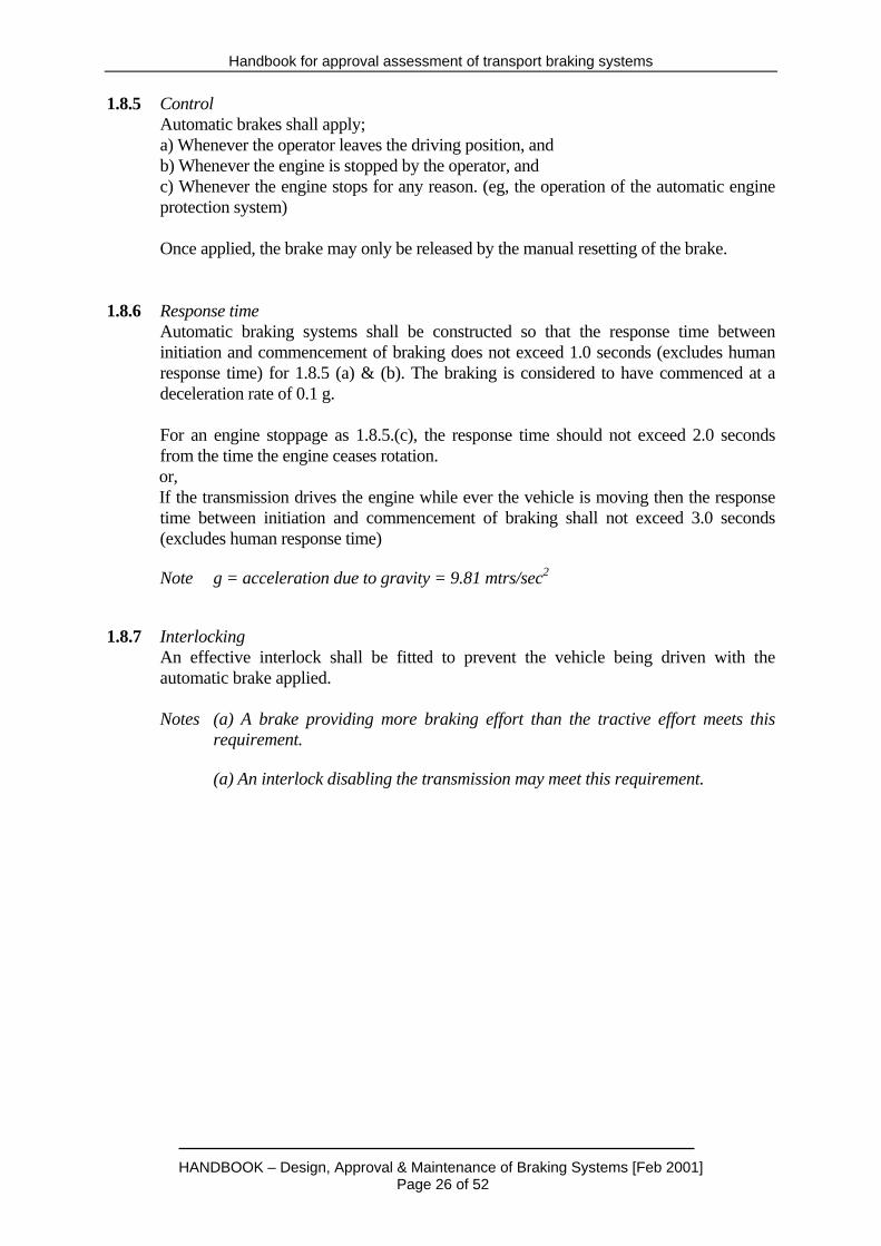
1.8.5 Control Automatic brakes shall apply; a) Whenever the operator leaves the driving position, and b) Whenever the engine is stopped by the operator, and c) Whenever the engine stops for any reason. (eg, the operation of the automatic engine
protection system) Once applied, the brake may only be released by the manual resetting of the brake. 1.8.6 Response time Automatic braking systems shall be constructed so that the response time between
initiation and commencement of braking does not exceed 1.0 seconds (excludes human response time) for 1.8.5 (a) & (b). The braking is considered to have commenced at a deceleration rate of 0.1 g.
For an engine stoppage as 1.8.5.(c), the response time should not exceed 2.0 seconds
from the time the engine ceases rotation. or, If the transmission drives the engine while ever the vehicle is moving then the response time between initiation and commencement of braking shall not exceed 3.0 seconds (excludes human response time)
Note g = acceleration due to gravity = 9.81 mtrs/sec2 1.8.7 Interlocking An effective interlock shall be fitted to prevent the vehicle being driven with the
automatic brake applied. Notes (a) A brake providing more braking effort than the tractive effort meets this
requirement. (a) An interlock disabling the transmission may meet this requirement.

Handbook for approval assessment of transport braking systems
HANDBOOK – Design, Approval & Maintenance of Braking Systems [Feb 2001] Page 27 of 52
SECTION 2 MARKING 2.1 PLATES & LABELS Labels shall not be manufactured from light metal. Labels shall be permanently fixed and indelibly marked. Engraved or etched and filled stainless steel labels are preferred. 2.2 COMPLIANCE PLATE A plate giving the following information shall be permanently affixed to each free-steered vehicle in an easily seen position. (a) The Braking System Approval/Certification number (b) The name of the manufacturer of the braking system (c) The date of manufacture of the braking system (d) The drawing number, issue number and date of the schematic and arrangement
drawing(s) (e) The minimum acceptable mean deceleration rates at speed for the vehicle at tare mass
(see 1.3.6), calculated from type testing, and the maximum acceptable response time, for each of the braking systems. The minimum acceptable mean deceleration rates at speed for the vehicle at tare mass (see 1.3.6) shall be nominated by the manufacturer and may not be less than those required to meet the requirements of 1.5.5, for service brakes and 1.6.4 for secondary brakes and 1.8.4 for automatic brakes.
(f) The minimum acceptable peak deceleration rates at speed for the vehicle at tare mass
(see 1.3.6), calculated from type testing, and the maximum acceptable response time, for each of the braking systems.
(g) The maximum Gross Vehicle Mass (see 1.3.9). (h) The maximum gross unbraked towing capacity. (i) The maximum holding grade for the Parking Brakes. Notes. (a) The information required above may be included on a general vehicle
compliance plate. (b) See Fig 1 for an example of a compliance plate.

Handbook for approval assessment of transport braking systems
HANDBOOK – Design, Approval & Maintenance of Braking Systems [Feb 2001] Page 28 of 52
FIGURE 1.
BRAKING SYSTEM COMPLIANCE PLATE
Approval/Cert. No.
Manufacturer
Date of manufacture
Approval/certification Drawing
Max (Vehicle) gross mass
Max (Trailer) gross mass
Minimum Acceptable Brake Performance for In-Service Testing At speed
(km/hr) Mean Deceleration rate (m/s2)
Peak Deceleration rate (m/s2)
Response time (s)
Service Brakes
Secondary Brakes Automatic Brakes
Maximum holding grade (%) Parking Brakes
2.3 SPECIFICATION PLATE A plate giving the following information should be permanently affixed to each free-steered vehicle in an easily seen position. (a) Wear indicator location and meaning (if fitted) (b) Any special oils used in braking systems (c) Any limitations on use or grade Note The information required above may be included in a general vehicle compliance plate
and/or added to Fig 1 above. 2.4 WARNINGS Warning labels shall be fitted as required to each braking system or component, in clearly visible locations, to identify hazards which may cause injury to persons.

Handbook for approval assessment of transport braking systems
HANDBOOK – Design, Approval & Maintenance of Braking Systems [Feb 2001] Page 29 of 52
Example Labels warning of high hydraulic pressures, stored pressure accumulators and the like. SECTION 3 TESTING 3.1 TYPE TESTING The following information for each new type and model of braking systems shall be determined. (a) A Statement of compliance or variation to each of the clauses of this Handbook. (b) Compliance by audit of the braking systems to the documents, including the
approval/certification drawing, provided by the manufacturer. The following testing shall be undertaken for each new type and model of braking system. Each system shall be tested to the requirements of Appendix C and Appendix D and the
test results reported. 3.2 MODIFIED COMPONENTS Where a component within the braking systems is modified, the regulatory authority or certifying body, may upon request from the manufacturer, allow the component to be tested individually or may require a complete re-test of the vehicle braking systems. Whenever a system is installed in any application where differences may occur, the braking system manufacturer shall undertake a complete re-test of the systems to ensure that no adverse changes to performance have occurred. 3.3 ROUTINE TESTING The integrity of each type tested, approved/certified vehicle braking system shall be confirmed by the braking system manufacturer as complying with the performance established during type testing for approval/certification. Routine testing shall meet the requirements of Appendix E. 3.4 IN-SERVICE TESTING In-service testing shall be undertaken by the user of any approved/certified braking system. In-service testing shall be undertaken at intervals no greater than that recommended by the manufacturer of the braking systems. A guide for the development of in-service testing is provided at Appendix F. Notes (a) Operating hours based, in-service testing is preferred to calendar intervals. (b) Manufacturers and users should develop testing intervals with regard to the
operating conditions at each mine. In-service brake testing should be included in the Standards of Engineering Practice for each Mine.

Handbook for approval assessment of transport braking systems
HANDBOOK – Design, Approval & Maintenance of Braking Systems [Feb 2001] Page 30 of 52
SECTION 4 DOCUMENTATION 4.1 General The manufacturer of the braking systems shall prepare and provide documentation to the testing authority, the regulatory authority and the purchaser of the free-steered vehicle which includes the braking systems. This information shall include specifications, drawings, parts information, service information, maintenance information, performance data, settings and adjustments. 4.2 Manufacturer to the testing authority The manufacturer of the braking system shall supply documents, including the following to the testing authority: 4.2.1 A schematic circuit and arrangement drawing of the braking system which includes: (a) All part numbers or a full design specification of each component. (b) Hose, pipe or tube sizes where length or bore size may affect performance of the
system. (c) The maximum vehicle mass (see 1.3.9) and maximum achievable speed of the
vehicle for which the braking system has been designed. (d) An illustration of the mechanical brakes, noting the highest surface temperature
and its' location. (see D6.3 (b)(v)) 4.2.2 A written description of the operation of the braking systems. 4.2.3 A maintenance data sheet which includes the manufacturer's recommendations on: (a) frequency of in-service testing (b) in-service brake testing procedures (c) in-service testing performance limits demonstrating the range of safe braking
performance. (d) adjustment procedures for the braking systems 4.2.4 A letter of request for approval/certification. 4.3 Testing Authority to the manufacturer (post assessment) The testing authority shall supply documentation to the braking system manufacturer, including (a) a detailed compliance report to this Handbook (b) actual test measurements, to assist in the auditing of any subsequent units
manufactured to the type covered by the compliance report. Note

Handbook for approval assessment of transport braking systems
HANDBOOK – Design, Approval & Maintenance of Braking Systems [Feb 2001] Page 31 of 52
Additional requirements may be required by the regulatory authority. 4.4 Manufacturer to the purchaser The braking system manufacturer shall supply to each purchaser of a braking system, the following documentation: (a) The schematic circuit drawing (see 4.2). (b) A letter of compliance, including the following information: (i) The statement: THIS FREE-STEERED VEHICLE, BRAKING SYSTEM, COMPLIES WITH
THE RELEVANT REQUIREMENTS OF THE BRAKING SYSTEM HANDBOOK, Feb. 2001.
(ii) The name and signature of the representative of the manufacturer authorised to
issue the letter of compliance. (iii) Name and address of the braking system manufacturer. (iv) Braking system model number. (v) The serial numbers of any relevant system components. (vi) Any relevant statutory approval, certification or test reports. (c) Details of maintenance and operational requirements, specifications and any other
drawings required to maintain the braking system in compliance with this Handbook. (d) A full report on the results of brake performance routine testing (including print-outs
from a calibrated brake testing instrument) signed by the senior engineering representative of the applicant in compliance with the requirements of Appendix E of this Handbook.
4.5 Manufacturer to the statutory authority If required, the manufacturer of the braking system shall supply to the statutory authority: All of the information required in 4.2, 4.3 and 4.4 above. 4.6 User to Manufacturer Users of approved braking systems should provide the manufacturer with detailed reports of any faults or defects detected under operating conditions.

Handbook for approval assessment of transport braking systems
HANDBOOK – Design, Approval & Maintenance of Braking Systems [Feb 2001] Page 32 of 52
APPENDIX A MEANS OF DEMONSTRATING CONTINUED COMPLIANCE WITH THIS HANDBOOK (Normative) A1 INTRODUCTION A manufacturer or supplier has an obligation to ensure that any braking systems supplied as conforming to this Handbook are manufactured to a design that has been type tested and certified/approved as conforming to this Handbook. All further braking systems of the type, if tested in accordance with the Handbook, shall conform to the requirements of the Handbook. This appendix sets out the following different means by which compliance with this Handbook can be demonstrated by the manufacturer or supplier: (a) The use of a product certification scheme eg the certification for electrical explosion
protected apparatus. (b) Assurance using the acceptability of the supplier's quality system. (c) Other such means proposed by the manufacturer or supplier and acceptable to the
customer. A2 SUPPLIER'S QUALITY SYSTEM Where the manufacturer or supplier can demonstrate an audited and registered quality management system complying with the requirements of the appropriate or stipulated Australian or International Standard for a supplier's quality system or systems, this may provide the necessary confidence that the specified requirements will be met. The quality assurance requirements need to be agreed between the customer and supplier and should include a quality or inspection and test plan to ensure product conformity. Guidance in determining the appropriate quality management system is given in AS/NZS ISO 9000.1-2 and AS/NZS ISO 9004.1. A3 OTHER MEANS OF ASSESSMENT If the above methods are considered inappropriate, determination of compliance with the requirements of this Handbook may be assessed from the results of testing coupled with the manufacturer's guarantee of product conformance. Irrespective of acceptable quality levels (AQLs) or test frequencies, the responsibility remains with the manufacturer or supplier to supply products that conform with the full requirements of the Handbook.

Handbook for approval assessment of transport braking systems
HANDBOOK – Design, Approval & Maintenance of Braking Systems [Feb 2001] Page 33 of 52
APPENDIX B TYPE TESTING - TEST CONDITIONS (Normative) B1 TEST COURSE B1.1 For deceleration tests The test course on which braking tests are carried out shall have sufficient length to enable them to be carried out safely. The grade of the test course- (a) at right angles to the direction of travel, shall be not more than three percent from
horizontal; and (b) in the direction of travel, shall be not more than one percent from the horizontal. The surface of the test course shall be hard, reasonably smooth and supported by a well compacted base. A sealed, paved surface is preferred. Surface or ground moisture may be present to the extent that it does not adversely affect braking performance. Note It is the intent that the test course should provide a co-efficient of adhesion of ≥
0.95. B1.2 For holding tests A ramp having a 25% grade and surface meeting the requirements of B1.1 above. or Equipment to provide sufficient pulling force and a calibrated tension gauge. B2 VEHICLE Any burnishing of brakes (i.e. conditioning of frictional surfaces before testing), (which is permissible) shall comply with the manufacturer's recommendations. The physical parameters that affect braking (e.g. tyre size, tyre pressure and brake adjustment) shall comply with the manufacturer's recommendations. Where manual adjustments are made during tests, all tests prior to the adjustments being made shall be repeated. B3 OPERATION Any precautions given by the manufacturer shall be observed. At the commencement of any test, operating fluids (e.g. engine oil and transmission oil) shall be at normal operating temperatures. Blades, buckets, dozers and other equipment shall be carried in the transport position recommended by the manufacturer. Any manually selected gear ratio shall be suitable for the speed of the vehicle just prior to the brake test. The power train may be disengaged just prior to completing the stop.

Handbook for approval assessment of transport braking systems
HANDBOOK – Design, Approval & Maintenance of Braking Systems [Feb 2001] Page 34 of 52
B4 TEST REPORT As transparency of testing is of great importance, test report should have a full description of testing including any applicable descriptive drawings and plans. The test report shall include the following: (a) The name of the testing authority. (b) Descriptions of the components/assemblies/vehicle tested. (c) A statement that the Test Course meets the requirements of this Appendix.

Handbook for approval assessment of transport braking systems
HANDBOOK – Design, Approval & Maintenance of Braking Systems [Feb 2001] Page 35 of 52
APPENDIX C TYPE TESTING - PERFORMANCE (Normative) C1 SCOPE This appendix sets out the procedure for the type testing of braking systems to determine that the performance meets the requirements of this Handbook. C2 TESTING AUTHORITY Braking systems and documents (see Section 4) shall be provided to the testing authority. The braking systems shall be installed and operational in the free-steered vehicle for which they were designed. C3 PRINCIPLE The tests simulate the braking systems being operated under conditions from which an assurance of safe operation conforming to this Handbook may be determined. C4 APPARATUS The testing shall be carried out with instruments meeting the requirements of Appendix G. C5 ACCURACY The calibration of all measuring instruments shall be traceable to national/international Standards and should be controlled through an accredited Quality Management System to AS/NZS ISO 9002. (min) C6 PROCEDURE C6.1 Normalisation The free-steered vehicle, loaded to its vehicle mass, shall be operated over a range of
speeds and loads for a sufficient length of time to ensure that operational stabilisation has occurred and that the temperature of oils, hydraulic fluids and the like have reached normal operating temperatures.
C6.2 Burnishing The burnishing (conditioning) of the brakes before testing is permissible. The burnishing
procedures indicated in manuals for the vehicle shall be verified with the manufacturer. C6.3 Information to be recorded For each test, measure and record; (i) The stopping distance (m) (ii) The speed immediately prior to the application of the brakes (km/hr) (iii) The maximum deceleration rate (m/s2) (iv) The mean deceleration rate (m/s2) (v) The response time between the application of the brakes and the beginning of
retardation. The beginning of retardation is considered to be 0.1 g.

Handbook for approval assessment of transport braking systems
HANDBOOK – Design, Approval & Maintenance of Braking Systems [Feb 2001] Page 36 of 52
(vi) The operating force applied to the pedal/button/lever by the operator. (N)
(vii) Evidence that the minimum stopping distances are achieved with operating forces less than the maximums nominated (see Table 1)
C6.4 Service Brake System - Performance (a) Forward (at vehicle mass) Drive the vehicle, loaded to its vehicle mass, on a test course meeting the requirements of
Appendix B at the maximum attainable speed in the forward direction. Apply the service brakes. Test.
Test five times with not more than 20 mins between each test. Record the results
applying to the longest recorded stopping distance in Table C1. (b) Reverse (at vehicle mass) Drive the vehicle, loaded to its vehicle mass, on a test course meeting the requirements of
Appendix B at the maximum attainable speed in the reverse direction. Apply the service brakes. Test.
Test five times with not more than 20 mins between each test. Record the results
applying to the longest recorded stopping distance in Table C1. (c) Forward (at tare mass) Drive the vehicle, with minimum load (tare), on a test course meeting the requirements of
Appendix B at the maximum attainable speed in the forward direction. Apply the service brakes. Test
Test five times with not more than 20 mins between each test. Record the results
applying to the longest recorded stopping distance in Table C1. (d) Reverse (at tare mass) Drive the vehicle on a test course, with minimum load (tare), meeting the requirements of
Appendix B at the maximum attainable speed in the reverse direction. Apply the service brakes. Test
Test five times with not more than 20 mins between each test. Record the results
applying to the longest recorded stopping distance in Table C1. (e) Holding At vehicle mass (see 1.3.9), drive the vehicle onto a ramp or slope having a grade ≥ 25%.
Apply the service brakes. Ensure that the brakes hold the vehicle for a period of not less than 5 mins without any further application or re-application of the brakes.
or, If the above requirement is impractical for test purposes, then the following alternative
may be employed. Apply a pulling force to the vehicle with the brake set and with the transmission in neutral under test conditions meeting the requirements of Appendix B. The pulling force shall be applied horizontally near to the ground. The force required shall be calculated as follows:
F = SIN Grade x M x 9.81 where

Handbook for approval assessment of transport braking systems
HANDBOOK – Design, Approval & Maintenance of Braking Systems [Feb 2001] Page 37 of 52
F = pulling force on the machine in Newtons Grade = the maximum operating grade in degrees M = 1.1 X Machine operating mass in kg C6.5 Secondary brake Repeat the tests nominated in C6.4 (a) & (c) above. Record the results in Table C1. Note The secondary brake may be combined in function and/or components with
other braking systems in which case, performance must comply with the requirements nominated for each of the systems.
C6.6 Automatic Brake (a) Repeat the tests nominated in C6.4 (a) & (c) above. Record the results in Table C1. Note The automatic brake may be combined in function and/or components with
other braking systems in which case, performance must comply with the requirements nominated for each of the systems.
(b) Drive the vehicle onto a ramp or slope have a grade ≥ 25%. Apply the automatic brakes.
Ensure that the brake holds the vehicle. or, If the above requirement is impractical for test purposes, then the following alternative
may be employed. Apply a pulling force to the vehicle with the brake set and with the transmission in neutral under test conditions meeting the requirements of Appendix B. The pulling force shall be applied horizontally near to the ground. The force required shall be calculated as follows:
F = SIN Grade x M x 9.81 where F = pulling force on the machine in Newtons Grade = the maximum operating grade in degrees M = 1.1 X Machine operating mass in kg (c) Confirm that each of the possible methods of automatic initiation of the automatic brake
meets the requirements of 1.8.5 and 1.8.6 for operation and response time.
Note Pressure gauges or other indicators of correct brake operation may be employed for this test.
C6.7 Parking brake Drive the vehicle at 110% of vehicle mass (see 1.3.9) onto a ramp or slope having a
grade ≥ 25%. Apply the park brakes. Ensure that the brake holds the vehicle. or, If the above requirement is impractical for test purposes, then the following alternative
may be employed. Apply a pulling force to the vehicle with the brake set and with the transmission in neutral under test conditions meeting the requirements of Appendix B. The pulling force shall be applied horizontally near to the ground. The force required shall be calculated as follows:
F = SIN Grade x M x 9.81 where
Handbook for approval assessment of transport braking systems
HANDBOOK – Design, Approval & Maintenance of Braking Systems [Feb 2001] Page 38 of 52
F = pulling force on the machine in Newtons Grade = the maximum operating grade in degrees M = 1.1 X Machine operating mass in kg Ensure that the Parking Brake holds the vehicle for a minimum period of 5 mins. Note The parking brake may be combined in function and/or components with other
braking systems in which case, performance must comply with the requirements nominated for each of the systems.

Handbook for approval assessment of transport braking systems
HANDBOOK – Design, Approval & Maintenance of Braking Systems [Feb 2001] Page 39 of 52
TABLE C1
BRAKING SYSTEM TEST RESULTS
Manufacturer
Date of test
Drawing Ref.
Name & model of free-steered vehicle
Brake Performance
Stop Dist. (m)
At speed (km/hr)
Max Decel. rate (m/s2)
Mean Decel. rate (m/s2)
Response time (s)
Operating force (N)
Service Brakes – Fwd (at veh. mass)
Service Brakes – Rev (at veh. mass)
Service Brakes – Fwd (at tare mass)
Service Brakes – Rev (at tare mass)
Secondary Brakes (at veh. mass)
Secondary Brakes (at tare mass)
Automatic Brakes (at veh. mass)
Automatic Brakes (at tare mass)
Brakes – Holding Ability Method of test Grade (%), or Force (N)
Service, Holds 5 mins ? Auto, Holds ?

Handbook for approval assessment of transport braking systems
HANDBOOK – Design, Approval & Maintenance of Braking Systems [Feb 2001] Page 40 of 52
Park, Hold 5 mins C7 TEST REPORT The test report shall include the following: (a) The name of the testing authority. (b) Descriptions of the components/assemblies/vehicle tested, including; Burnishing procedure (if any) Tyres fitted during test (specification) Any other information considered relevant by the testing authority which may
have affected the test results. (c) The tests carried out. (d) The test results. (e) A statement as to whether or not the tests carried out satisfy this Appendix.

Handbook for approval assessment of transport braking systems
HANDBOOK – Design, Approval & Maintenance of Braking Systems [Feb 2001] Page 41 of 52
APPENDIX D TYPE TESTING - TEMPERATURE (normative) D1 SCOPE This Appendix sets out the procedure for the type testing of braking systems for surface temperature and the effects of temperature on brake performance. D2 TESTING AUTHORITY Braking systems and documents (see Section 4) shall be provided to the testing authority. The braking systems shall be installed and operational in the free-steered vehicle for which they were designed. D3 PRINCIPLE The tests simulate the braking systems being operated under conditions from which an assurance of safe operation conforming to this Handbook may be determined. D4 APPARATUS The testing shall be carried out with instruments meeting the requirements of Appendix G. D5 ACCURACY The calibration of all measuring instruments shall be traceable to national/international Standards and should be controlled through an accredited Quality Management System to AS/NZS ISO 9002. D6 PROCEDURE D6.1 Normalisation The free-steered vehicle, loaded to its vehicle mass, shall be operated over a range of
speeds and loads for a sufficient length of time to ensure that operational stabilisation has occurred and that the temperature of oils, hydraulic fluids and the like have reached normal operating temperatures.
D6.2 Burnishing The burnishing (conditioning) of the brakes before testing is permissible. The burnishing
procedures indicated in manuals for the vehicle shall be verified with the manufacturer. D6.3 Service Brake System - Performance (a) For a vehicle designed to be driven primarily in the forward direction, drive the vehicle,
loaded to 110% of' vehicle mass, on a test course, meeting the requirements of Appendix B at the maximum attainable speed in the forward direction. Apply the service brakes.
Test five times at intervals between successive stops of not more than 20 min and
provided that the entire test shall be completed in 40 mins. For vehicles designed to operate equally in both forward and reverse directions, the tests
shall be repeated for the reverse direction.

Handbook for approval assessment of transport braking systems
HANDBOOK – Design, Approval & Maintenance of Braking Systems [Feb 2001] Page 42 of 52
(b) Measure and record: (i) The stopping distance (m) (ii) The speed immediately prior to the application of the brakes (km/hr) (iii) The maximum deceleration rate (m/s2) (iv) The mean deceleration rate (m/s2) (v) The highest surface temperature of any part of the braking system. The location
of the highest surface temperatures shall be described and added to arrangement drawing(s). (0C) (see 4.2.1)
(vi) The ambient temperature (0C) Record the test results at Table D1. Optical thermal imaging systems should be employed for the measurement of temperatures, providing the instrument is: (a) Calibrated (b) Corrected for colour temperature The stopping distance of any stop shall not be more than 125% of the stopping distance of the shortest stop. The highest surface temperature of the service brakes shall not exceed 1500 C.
Handbook for approval assessment of transport braking systems
HANDBOOK – Design, Approval & Maintenance of Braking Systems [Feb 2001] Page 43 of 52
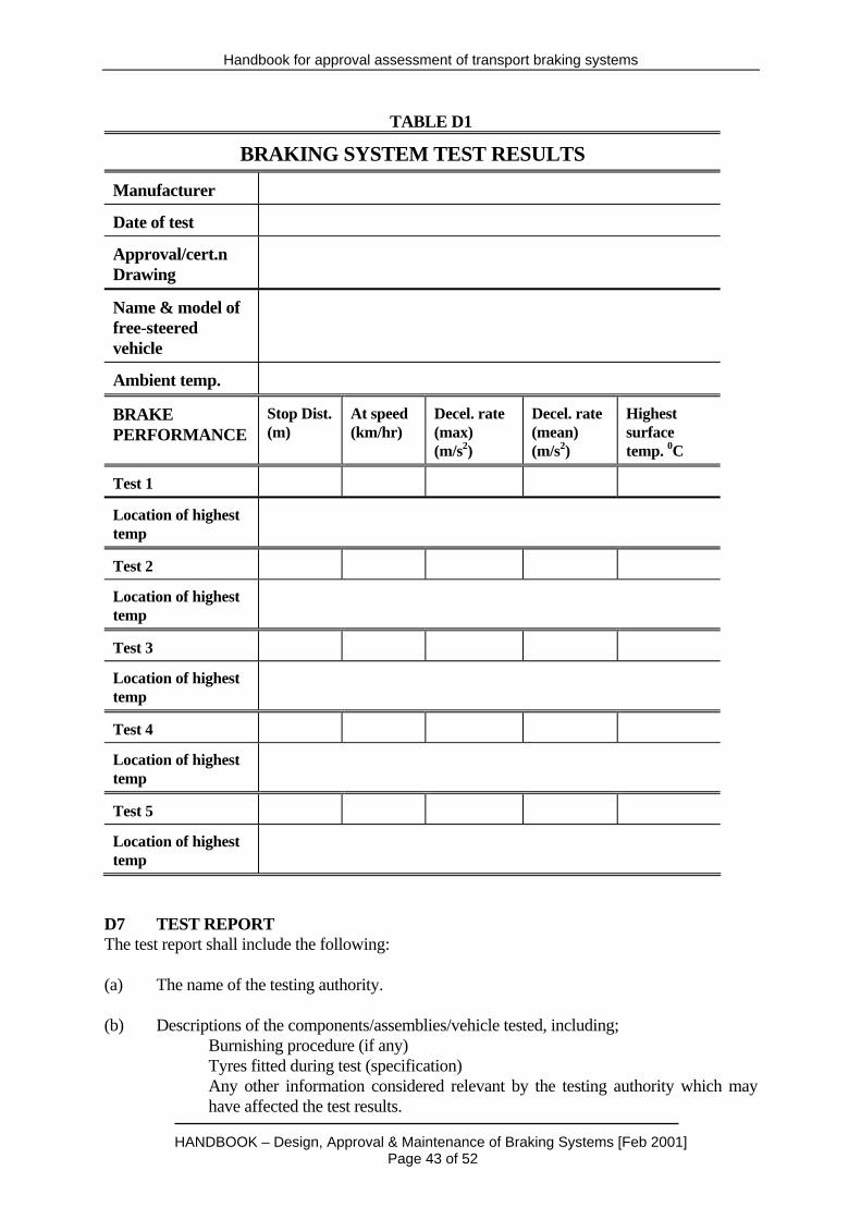
TABLE D1
BRAKING SYSTEM TEST RESULTS
Manufacturer
Date of test
Approval/cert.n Drawing
Name & model of free-steered vehicle
Ambient temp.
BRAKE PERFORMANCE
Stop Dist. (m)
At speed (km/hr)
Decel. rate (max) (m/s2)
Decel. rate (mean) (m/s2)
Highest surface temp. 0C
Test 1
Location of highest temp
Test 2
Location of highest temp
Test 3
Location of highest temp
Test 4
Location of highest temp
Test 5
Location of highest temp
D7 TEST REPORT The test report shall include the following: (a) The name of the testing authority. (b) Descriptions of the components/assemblies/vehicle tested, including; Burnishing procedure (if any) Tyres fitted during test (specification) Any other information considered relevant by the testing authority which may
have affected the test results.

Handbook for approval assessment of transport braking systems
HANDBOOK – Design, Approval & Maintenance of Braking Systems [Feb 2001] Page 44 of 52
(c) The tests carried out. (d) The test results. (e) A statement as to whether or not the tests carried out satisfy this Appendix.

Handbook for approval assessment of transport braking systems
HANDBOOK – Design, Approval & Maintenance of Braking Systems [Feb 2001] Page 45 of 52
APPENDIX E ROUTINE TESTING (normative) E1 SCOPE This Appendix sets out the procedure for the routine testing of serially produced approved/certified braking systems as installed in free-steered vehicles. E2 PRINCIPLE The tests indicate that serially produced braking systems provide performance indication within an acceptable tolerance of the results measured by the testing authority during type testing. The tests indicate that the configuration and function of brake controls conform to the design approved/certified. E3 APPARATUS The testing should be carried out with instruments meeting the requirements of Appendix G. E4 ACCURACY The calibration of all measuring instruments shall be traceable to national/international Standards and should be controlled through an accredited Quality Management System to AS/NZS ISO 9002. E5 PROCEDURE E5.1 Normalisation The free-steered vehicle, at tare mass, shall be operated over a range of speeds and loads
for a sufficient length of time to ensure that operational stabilisation has occurred and that the temperature of oils, hydraulic fluids and the like have reached normal operating temperatures.
E5.2 Burnishing The burnishing (conditioning) of the brakes before testing is permissible. The burnishing
procedures indicated in manuals for the vehicle shall be verified with the manufacturer. E5.3 Service Brake Testing (a) Forward (at tare mass) Drive the vehicle, with minimum load (tare), on a test course meeting the requirements of
Appendix B at the maximum attainable speed in the forward direction. Apply the service brakes. Test
Test three times with not more than 20 mins between each test. Record the results
applying to the longest recorded stopping distance in Table E1. (b) Reverse (at tare mass) Drive the vehicle on a test course, with minimum load (tare), meeting the requirements of
Appendix B at the maximum attainable speed in the reverse direction. Apply the service brakes. Test
Test three times with not more than 20 mins between each test. Record the results
applying to the longest recorded stopping distance in Table E1.

Handbook for approval assessment of transport braking systems
HANDBOOK – Design, Approval & Maintenance of Braking Systems [Feb 2001] Page 46 of 52
(c) Holding Drive the vehicle at vehicle mass (see 1.3.9) onto a ramp or slope having a grade ≥ 25%.
Apply the service brakes. Ensure that the brakes hold the vehicle for a period of not less than 5 mins without any further application or re-application of the brakes.
or, If the above requirement is impractical for test purposes, then the following alternative
may be employed. Apply a pulling force to the vehicle with the brake set and with the transmission in neutral under test conditions meeting the requirements of Appendix B. The pulling force shall be applied horizontally near to the ground. The force required shall be calculated as follows:
F = SIN(Grade) x M x 9.81 where F = pulling force on the machine in Newtons Grade = the maximum operating grade in degrees M = 1.1 X Machine operating mass in kg E5.4 Secondary brake Testing Repeat the tests nominated in E5.3 (a) & (c) above. Record the results in Table E1. Note The secondary brake may be combined in function and/or components with
other braking systems in which case, performance must comply with the requirements nominated for each of the systems.
E5.5 Automatic Brake Testing (a) Repeat the tests nominated in E5.3 (a) & (c) above. Record the results in Table E1. Note The automatic brake may be combined in function and/or components with
other braking systems in which case, performance must comply with the requirements nominated for each of the systems.
(b) Drive the vehicle onto a ramp or slope having a grade ≥ 25%. Apply the automatic
brakes. Ensure that the brake holds the vehicle. or, If the above requirement is impractical for test purposes, then the following alternative
may be employed. Apply a pulling force to the vehicle with the brake set and with the transmission in neutral under test conditions meeting the requirements of Appendix B. The pulling force shall be applied horizontally near to the ground. The force required shall be calculated as follows:
F = SIN(Grade) x M x 9.81 where F = pulling force on the machine in Newtons Grade = the maximum operating grade in degrees M = 1.1 X Machine operating mass in kg

Handbook for approval assessment of transport braking systems
HANDBOOK – Design, Approval & Maintenance of Braking Systems [Feb 2001] Page 47 of 52
E5.6 Parking brake Testing Drive the vehicle at vehicle mass (see 1.3.9) onto a ramp or slope have a grade ≥ 25%.
Apply the park brakes. Ensure that the brake holds the vehicle. or, If the above requirement is impractical for test purposes, then the following alternative
may be employed. Apply a pulling force to the vehicle with the brake set and with the transmission in neutral under test conditions meeting the requirements of Appendix B. The pulling force shall be applied horizontally near to the ground. The force required shall be calculated as follows:
F = SIN(Grade) x M x 9.81 where F = pulling force on the machine in Newtons Grade = the maximum operating grade in degrees M = 1.1 X Machine operating mass in kg Note The parking brake may be combined in function and/or components with other braking
systems in which case, performance must comply with the requirements nominated for each of the systems.
E5.7 Information to be recorded For each test, the measure and record; (ii) The speed immediately prior to the application of the brakes (km/hr) (iv) The mean deceleration rate (m/s2) (v) The response time between the application of the brakes and the beginning of
retardation. The beginning of retardation is considered to be 0.1 g. (vi) The operating force applied to the pedal/button/lever by the operator. (N) E6 TEST REPORT The test report shall include the following: (a) The name of the organisation undertaking the testing, and the name of the person
responsible for the testing. (b) Descriptions of the components/assemblies/vehicle tested, including; The serial No. of the vehicle The date of manufacture and the date of test (may be the same) Burnishing procedure (if any) Tyres fitted during test (specification) Any other information considered relevant by the testing authority which may
have effected the test results. (c) The tests carried out.

Handbook for approval assessment of transport braking systems
HANDBOOK – Design, Approval & Maintenance of Braking Systems [Feb 2001] Page 48 of 52
(d) The test results. (e) A statement as to whether or not the tests carried out satisfy this Appendix.

Handbook for approval assessment of transport braking systems
HANDBOOK – Design, Approval & Maintenance of Braking Systems [Feb 2001] Page 49 of 52
APPENDIX F IN-SERVICE TESTING PROCEDURE (Informative) F1 SCOPE This Appendix sets out a procedure for evaluating and monitoring the performance of braking systems fitted to free-steered vehicles, in service. This procedure is a guide only. Operators of vehicles with approved/certified braking systems should develop unique maintenance and testing procedures within their maintenance management systems to ensure the safe and effective continued operation of braking systems. Note Users should develop maintenance management systems in consultation with the
manufacturer. F2 PRINCIPLE The tests simulate the braking systems being operated under conditions from which an assurance of safe operation conforming to this Handbook may be determined. The test results are compared to the manufacturer’s recommendations as noted on the Compliance Plate. (see 2.2, Fig. 1) F3 APPARATUS The testing should be carried out with instruments meeting the requirements of Appendix G. F4 ACCURACY The calibration of all measuring instruments should be traceable to national/international Standards and should be controlled through an accredited Quality Management System to AS/NZS ISO 9002. F5 PERFORMANCE F5.1 Information to be recorded For each test, measure and record; (i) The speed immediately prior to the application of the brakes (km/hr) (ii) The mean deceleration rate (m/s2) (iii) The peak deceleration rate (m/s2) (iv) The response time between the application of the brakes and the beginning of
retardation. The beginning of retardation is considered to be 0.1 g. (v) The operating force applied to the pedal/button/lever by the operator. (N) Note The peak deceleration rate is an indicator of the ability of brakes to hold on a
grade. A rate of less than 2.8 m/s² indicates that the brakes may not hold on a 25% grade.
Handbook for approval assessment of transport braking systems
HANDBOOK – Design, Approval & Maintenance of Braking Systems [Feb 2001] Page 50 of 52
F5.2 Service brakes a) Service brakes shall be tested while the vehicle is unladen, at tare mass, (see 1.3.6) and travelling on a surface and grades as close as practicable to the requirements of Appendix B. at the recommended testing speed for the vehicle, subject to a maximum of 30 km/h. Retarders or hydrostatic systems may be used during the test. Tests should be repeated a minimum of three times and the lowest deceleration rate recorded. Note Where a test course is not available, meeting the requirements of Appendix B,
then operators should select a test course for in-service testing which will be maintained and consistent for long periods. The results from the same test course may then be used to indicate performance trends which may then be employed within the maintenance management system to predict service/repair requirements. Testing should always be done in the same direction of travel on the test course.
The mean deceleration rate shall not be less than that recommended by the manufacturer and included on the Compliance Label. (see 2.2 Fig. 1) Note Decreases in the mean deceleration rate for subsequent in-service tests will
indicate a reduction of service brake performance and a requirement for maintenance, service, adjustment or repair.
F5.3 Secondary and Automatic brakes Secondary braking systems shall be tested in accordance with the manufacturer's specification. F5.4 Park brakes Parking brakes shall be capable of holding the vehicle stationary in a fully loaded condition on the steepest grade that it will encounter in both the forward and the reverse directions, subject to a minimum incline of 25%. NOTES: (a) This test should not submit the operator or observers to any danger. (b) The test can be a live test or a stall test that will apply an equivalent braking force. F6 TEST REPORT The test report shall include the following: (a) The name of the organisation undertaking the testing, and the name of the person
responsible for the testing. (b) Descriptions of the components/assemblies/vehicle tested. (c) The tests carried out. (d) The test results. (e) A statement as to whether or not the tests carried out satisfy this Appendix.

Handbook for approval assessment of transport braking systems
HANDBOOK – Design, Approval & Maintenance of Braking Systems [Feb 2001] Page 51 of 52
APPENDIX G SPECIFICATION OF TEST INSTRUMENTS (Normative) G1 SCOPE This appendix sets out the performance requirements for instruments used in the measurement of brake performance parameters. G2 BRAKE TESTING INSTRUMENT Any brake testing instrument employed to demonstrate compliance with this Handbook shall be calibrated. Accuracy ± 1.5% g Repeatability ± 2.0% g Range 0 - 140% g (g = 9.81 m/s2) Pedal force transducer 0 - 2000 N Calibration ± 0.1% g G3 GENERAL INSTRUMENTATION In general terms, the permissible deviations of instruments/sensors/transducers, when combined with power supplies and converters, for engine related parameters shall be as shown in Table G1 (based on ISO 8178-1 : 1996.08.15): TABLE G1
No. Item Permissible deviation
based on max values
Repeatability
1 Mass +/- 2 % +/- 1 %
2 Power +/- 4 % (calc) +/- 2 %
3 Temp (surface) +/- 2 K +/- 0.5 K
4 Force +/- 4% +/- 2%
5 Oil temp +/- 2 K +/- 0.5 K
6 Ambient temperature +/- 2 K +/- 1 K
7 Atmospheric pressure +/- 1 % +/- 0.5 %
8 Relative humidity +/- 2 % +/- 0.5 %

Handbook for approval assessment of transport braking systems
HANDBOOK – Design, Approval & Maintenance of Braking Systems [Feb 2001] Page 52 of 52
APPENDIX H DOCUMENTS REFERENCED IN THE PREPARATION OF THIS HANDBOOK (informative) H1 SCOPE This appendix lists the documents referenced by the committee in the preparation of this Handbook. H2 LIST MDG1 Handbook Issue A; Rev 1; File M86/0349 Free-steered vehicles in underground coal mines CMRA 1999 Coal Mines (Underground) Regulation 1999 AS 2958.1 1995 Earth-moving machinery - Safety Part 1 : Wheeled Machines - Brakes SAE J843 Brake system, Road Test Code SAE J1329 Minimum performance criteria for braking systems for specialised
rubber-tyred, self-propelled underground mining machines. Title 49, Vol 5 Code of federal regulations (US) Parts 400 - 999 Hydraulic and electric braking systems E/ECE/324 Uniform provisions concerning the approval of passenger cars Reg 13
with regard to braking. CAN/CSA- Braking performance - Rubber tyred self propelled underground mining M424.3-M90 machinery. ISO 3450 Earth moving machinery - Braking Systems of rubber-tyred machines-
Systems and performance requirements and test procedures. SABS 1589.1994 Braking performance of trackless underground mining vehicles, LHD's
and Dump Trucks. Dept. Minerals (NSW) Compendium