Embed Size (px)
Citation preview
213www.lovejoy-inc.com GD-
JWJI
SC
JSF
MC
GH
PG
DD
TSP
UJ
VSD
RSL
DED
JWJIS
CJ
SFM
CG
HP
GD
DT
SPU
JVSD
RSLD
ED
213www.lovejoy-inc.com
JWJI
SC
JSF
MC
GH
PG
DD
TSP
UJ
VSD
RSL
DED
JWJIS
CJ
SFM
CG
HP
GD
DT
SPU
JVSD
RSLD
ED
GD-1
In This Section:■■ Horizontal■Cover■Style
■■ Vertical■Cover■Style
■■ Full■Spacer■Style
■■ Half■Spacer■Style
Grid
JWJI
SC
JSF
MC
GH
PG
DD
TSP
UJ
VSD
RSL
DED
JWJIS
CJ
SFM
CG
HP
GD
DT
SPU
JVSD
RSLD
ED
214 630-852-0500
When■using■Lovejoy■products,■you■must■follow■these■instructions■and■take■the■following■precautions.■Failure■to■do■so■may■cause■the■power■transmission■product■to■break■and■parts■to■be■thrown■with■sufficient■force■to■cause■severe■injury■or■death.
Refer■to■this■Lovejoy■Catalog■for■proper■selection,■sizing,■horsepower,■torque■range,■and■speed■range■of■power■transmission■products,■including■elastomeric■elements■for■couplings.■Follow■the■installation■instructions■included■with■the■product,■and■in■the■individual■product■catalogs■for■proper■installation■of■power■transmission■products.■Do■not■exceed■catalog■ratings.
During■start■up■and■operation■of■power■transmission■product,■avoid■sudden■shock■loads.■Coupling■assembly■should■operate■quietly■and■smoothly.■If■coupling■assembly■vibrates■or■makes■beating■sound,■shut■down■immediately,■and■recheck■alignment.■Shortly■after■initial■operation■and■periodically■thereafter,■where■applicable,■inspect■coupling■assembly■for:■alignment,■wear■of■elastomeric■element,■bolt■torques,■and■flexing■elements■for■signs■of■fatigue.■Do■not■operate■coupling■assembly■if■alignment■is■improper,■or■where■applicable,■if■elastomeric■element■is■damaged,■or■worn■to■less■than■75%■of■its■original■thickness.
Do■not■use■any■of■these■power■transmission■products■for■elevators,■man■lifts,■or■other■devices■that■carry■people.■If■the■power■transmission■product■fails,■the■lift■device■could■fall■resulting■in■severe■injury■or■death.
For■all■power■transmission■products,■you■must■install■suitable■guards■in■accordance■with■OSHA■and■American■Society■of■Mechanical■Engineers■Standards.■Do■not■start■power■transmission■product■before■suitable■guards■are■in■place.■Failure■to■properly■guard■these■products■may■result■in■severe■injury■or■death■from■personnel■contacting■moving■parts■or■from■parts■being■thrown■from■assembly■in■the■event■the■power■transmission■product■fails.
If■you■have■any■questions,■contact■the■Lovejoy■Engineering■Department■at■1-630-852-0500.
Safety Warning
GD-2
Grid
JWJI
SC
JSF
MC
GH
PG
DD
TSP
UJ
VSD
RSL
DED
JWJIS
CJ
SFM
CG
HP
GD
DT
SPU
JVSD
RSLD
ED
215www.lovejoy-inc.com
Table of Contents
GD-3
Grid
Overview■......................................................................................................................................216■.................... GD-4
Selection■Process■........................................................................................................................217■.................... GD-5
Application■Service■Factors■>■Selection■Data■.............................................................................219■.................... GD-7
Grid■Coupling■Selection■Worksheet■.............................................................................................221■.................... GD-9
Standard■Coupling■>■Performance■Data■.....................................................................................222■.................. GD-10
Standard■Coupling■>■Dimensional■Data■......................................................................................223■.................. GD-11
Spacer■Style■>■Performance■/■Dimensional■Data■........................................................................224■.................. GD-12
Spacer■Style■>■Spacer■Hub■Selection■.........................................................................................225■.................. GD-13
Misalignment■Capability■>■Item■Selection■....................................................................................226■.................. GD-14
Industry■Standard■Interchange■Chart■>■Item■Selection■...............................................................227■.................. GD-15
Grid■Coupling■Hubs■–■Inch■Bore■/■Keyway■>■Item■Selection■.......................................................228■.................. GD-16
Grid■Coupling■Hubs■–■Metric■Bore■/■Keyway■>■Item■Selection■....................................................229■.................. GD-17
Grid■Coupling■–■Taper■Lock■Hubs■>■Item■Selection■.....................................................................230■.................. GD-18
Grid■Coupling■–■Component■Part■Numbers■>■Item■Selection■......................................................231■.................. GD-19
Running Section Page No. Page No.
JWJI
SC
JSF
MC
GH
PG
DD
TSP
UJ
VSD
RSL
DED
JWJIS
CJ
SFM
CG
HP
GD
DT
SPU
JVSD
RSLD
ED

216 630-852-0500GD-4
Grid
Overview
The Power of Torsional DampeningLovejoy■is■pleased■to■be■able■to■provide■quality■grid■couplings■covering■a■large■number■of■industry■standard■sizes■and■lengths.■■The■Lovejoy■grid■style■coupling■has■proven■itself■in■performance■and■popularity■over■a■wide■range■of■applications.
Lovejoy’s■grid■style■coupling■design■has■demonstrated■its■ability■to■■dampen■vibration■by■as■much■as■30%■and■can■cushion■shock■loads■that■could■cause■damage■to■both■the■driving■and■driven■equipment.■The■tapered■grid■spring■design■absorbs■impact■energy■by■spreading■the■energy■out■over■the■full■length■of■the■grid■spring■thus■reducing■the■magnitude■of■the■torque■spikes.■■
The■Lovejoy■design■uses■a■curved■hub■tooth■profile■which■creates■a■progressive■contact■with■the■flexible■grid■spring■as■the■application■torque■increases.■■This■feature■provides■a■more■effective■and■efficient■transmission■of■power■in■properly■aligned■couplings.■■
Lovejoy’s■versatile■design■of■industry■standard■hubs■and■grid■springs■for■both■horizontal■and■vertical■cover■styles■allow■Lovejoy■couplings■to■be■interchangeable■with■other■industry■standard■grid■couplings■and■components.■■
Proper■grid■coupling■installation■and■maintenance■can■add■to■a■longer■coupling■life.■■■Grid■spring■replacement■is■simple■and■can■be■performed■at■a■fraction■of■the■cost■and■time■of■a■complete■coupling.
Features■■ High■tensile,■shot-peened■alloy■steel■grid■springs■and■precision■machined■hubs■ensure■superior■coupling■performance■and■long■life.
■■ Lovejoy’s■grid■couplings■with■tapered■grids■are■designed■to■be■interchangeable■with■other■industry■standard■grid■couplings■with■both■horizontal■and■vertical■grid■covers.
■■ Lovejoy■grid■couplings■are■designed■for■ease■of■installation■and■maintenance■reducing■labor■and■downtime■costs.
■■ The■torsional■flexibility■and■resilience■of■Lovejoy■grid■couplings■helps■reduce■vibration■and■cushions■shock■and■impact■loads.
■■ Cover■fasteners■can■be■provided■in■either■Inch■or■Metric■sizes.
■■ Excellent■for■use■in■applications■where■the■equipment■is■close■coupled■or■spaced■apart■requiring■a■spacer■style■coupling■arrangement.■■
■■ Stock■spacer■designs■are■available■or■requests■for■custom■spacer■lengths■can■be■addressed■by■Lovejoy■engineering.
Horizontal Split Cover Design
■■ Ideal■for■limited■space
■■ Allows■easy■access■to■the■grid■spring
■■ Well■suited■for■reversing■applications
■■ Lightweight■die-cast■aluminum■grid■cover
Vertical Split Cover Design
■■ Ideal■for■higher■operating■speeds
■■ Allows■easy■access■to■the■grid■spring
■■ Cover■is■manufactured■from■stamped■steel■for■strength
Full Spacer Design – Horizontal Cover
■■ Drop-out■design■ideal■for■pump■applications■and■servicing■
■■ Stock■sizes■1020■thru■1090
■■ Lightweight■die-cast■aluminum■grid■cover
Half Spacer Design – Horizontal Cover
■■ Offers■additional■BSE■dimensions
■■ Lightweight■die-cast■aluminum■grid■cover
WARNINGYou■must■refer■to■page■GD-2■(page■214)■for■Important■Safety■Instructions■and■Precautions■for■the■selection■and■use■of■these■products.■■Failure■to■follow■the■instructions■and■precautions■could■lead■to■severe■injury■or■death.
JWJI
SC
JSF
MC
GH
PG
DD
TSP
UJ
VSD
RSL
DED
JWJIS
CJ
SFM
CG
HP
GD
DT
SPU
JVSD
RSLD
ED
217www.lovejoy-inc.com GD-5
Grid
Selection Process
The■following■information■is■necessary■when■making■a■Grid■coupling■selection:
■■ Description■of■motor■or■engine,■the■horse■power■(or■KW),■and■RPM■at■slowest■coupling■speed■while■under■load
■■ Description■of■the■driven■equipment■
■■ Shaft■and■keyway■sizes■and■the■type■of■fit■for■driver■and■driven■equipment■(clearance■or■interference)**
■■ Shaft■separation■(BSE)
■■ Physical■space■limitations■(see■Application■Worksheet)
■■ Determine■what■the■environmental■conditions■will■be,■■such■as■temperature,■corrosive■conditions,■interference■from■surrounding■structures,■etc.
**■By■default,■sizes■1020■–■1090■will■be■clearance■fit,■sizes■1100■–■1200■will■be■interference■fit.■■
**■Lovejoy■machines■all■bores■and■keyways■to■meet■the■dimensional■and■tolerance■specifications■per■ANSI/AGMA■9002-B04■for■inch■bores,■or■ISO■286-2■for■metric■bores.
Typical■grid■couplings■consist■of■two■grid■hubs,■a■grid■spring,■and■a■cover■assembly.■■When■the■shaft■separation■requires■a■spacer■style■coupling,■the■coupling■will■consist■of■two■shaft■hubs,■two■spacer■hubs,■a■grid■spring,■and■a■horizontal■cover■assembly.
The■following■charts■are■available■to■assist■in■making■the■best■possible■grid■coupling■selection:
■■ Coupling■Selection■Worksheet,■ Page■GD-9
■■ Grid■Standard■Interchange■Chart,■ Page■GD-15
■■ Application■Service■Factors,■ Pages■GD-7■and■GD-8
■■ General■Service■Factors,■ Page■GD-6■(bottom)
■■ Performance■and■Dimensional■ Page■GD-10■thru■GD-11■Data■for■Standard■Grid■Couplings
■■ Performance■and■Dimensional■ Page■GD-12■Data■for■Spacer■Grid■Couplings
■■ Grid■Coupling■Part■Numbers■ Page■GD-16■thru■GD19■for■Standard■Components
Formulas Used To Calculate Torque:Application■Torque■(in-lbs)■■■=■■■(■horse■power■x■63025■)■
RPM
Application■Torque■(Nm)■■■■■■=■■■(■horse■power■x■9550■)■RPM
Selection■Torque■■=■■Application■Torque■■x■■Service■Factor
High Peak Loads and Brake ApplicationsFor■applications■where■high■peak■loads■or■high■braking■torques■might■be■present,■the■following■additional■information■will■be■necessary:
■■ System■peak■torque■and■frequency
■■ Duty■cycle
■■ Brake■torque■rating
The■selection■torque■formula■is■similar■to■the■formula■shown■above■except■that■the■application■torque■should■be■doubled■prior■to■applying■the■service■factor.■■
Application■Torque■(in-lbs)■■■=■■■(■horse■power■x■63025■)■RPM
Application■Torque■(Nm)■■■■■■=■■■(■horse■power■x■9550■)■RPM
Selection■Torque■■=■■2■x■Application■Torque■■x■■Service■Factor
Please■feel■free■to■contact■Lovejoy■Application■Engineering■or■Technical■Support■for■assistance■with■additional■grid■coupling■questions.
Step 1:■■■Determine■the■application■torque■using■the■formula■shown■above.
Step 2:■■■Select■the■Service■Factor■from■the■charts■on■pages■GD-7■and■GD-8.■For■applications■not■displayed■use■the■chart■shown■to■the■right.■■Determine■the■Selection■Torque■using■the■formula■shown■above.■
Step 3:■■■Using■the■selection■torque■as■calculated,■refer■to■the■Performance■Chart■on■page■GD-10■to■determine■the■minimum■size■grid■coupling■that■will■accommodate■the■torque.
Step 4:■■■Compare■the■maximum■bore■for■the■size■selected■and■ensure■the■required■bore■sizes■do■not■exceed■the■maximum■allowable.■If■the■required■bore■size■is■larger,■step■up■to■the■next■size■coupling■and■check■to■see■if■the■bore■sizes■will■fit.
Step 5: ■■Using■the■selected■coupling■size,■compare■the■bore■and■keyway■sizes■with■the■charts■located■on■pages■GD-16■thru■GD-17■for■UPC■part■numbers.
Step 6: ■■Contact■your■local■industrial■supplier■with■the■part■numbers■to■place■your■order.
See■the■Selection■Example■process■on■the■next■page.
Grid Coupling Selection Process
JWJI
SC
JSF
MC
GH
PG
DD
TSP
UJ
VSD
RSL
DED
JWJIS
CJ
SFM
CG
HP
GD
DT
SPU
JVSD
RSLD
ED
Steps In Selecting A Grid Coupling
218 630-852-0500GD-6
Grid
Selection Process
Application DescriptionA■company■would■like■to■use■a■grid■coupling■to■connect■a■standard■AC■electric■motor■to■a■rotary■lobe■compressor.■■The■electric■motor■is■rated■for■60■horsepower■running■at■1,760■RPM.■The■shaft■size■on■the■electric■motor■(driver)■is■2-1/8■inches■with■a■standard■1/2”■square■key.■■The■shaft■size■on■the■compressor■(driven)■is■48■millimeters■with■a■standard■14mm■key.■■Both■the■motor■and■compressor■shaft■are■3■inches■long■and■the■gap■(BSE)■between■the■shaft■ends■is■1/8■inch.■
The■following■steps■provide■an■excellent■selection■process■that■will■work■for■most■standard■grid■coupling■selections.■■For■assistance■in■this■selection■process,■feel■free■to■contact■Lovejoy■Application■Engineering■or■Technical■Support.
Step 1: ■■Using■the■information■provided■by■the■customer,■determine■the■application■torque:
■ Application■Torque■(in-lbs)■■■=■■■(■horse■power■x■63025■)■RPM
■ for■this■example:
■ Application■Torque■(in-lbs)■■■=■■■(■60■x■63025■)■■■=■2,149■in-lbs1,760
Step 2:■■■Select■the■application■service■factor■from■the■chart■on■pages■GD-7■and■GD-8■to■determine■which■value■best■corresponds■to■an■electric■motor■driven■rotary■lobe■style■compressor.■■■In■the■charts■find■the■application■category■‘Compressors’,■‘Rotary■lobe■and■vane’,■and■under■the■column■for■‘Electric■Motors’,■is■the■service■factor■number■1.25.
■ ■If■the■service■factor■did■not■appear■on■the■service■factor■charts■for■the■defined■application,■a■generic■value■could■be■selected■from■the■chart■located■on■the■right■side■of■this■page.
Step 3:■■Calculate■the■Selection■Torque■for■the■application:
■ Selection■Torque■■=■■Application■Torque■■x■■Service■Factor
■ Selection■Torque■■=■■2,149■in-lbs■x■1.25■■=■■2,687■in-lbs
Step 4:■■■Reference■the■Grid■Coupling■Performance■and■Dimensional■data■on■pages■GD-10■and■GD-11.■■Use■the■Selection■Torque■to■make■an■initial■selection■based■on■the■nominal■torque■allowed■for■the■coupling■size.■■The■first■coupling■size■that■can■accommodate■2,687■in-lbs■or■torque■is■the■size■1050■grid■coupling■with■a■nominal■torque■rating■of■3,850■in-lbs.■■
Step 5:■■■Note,■that■the■electric■motor’s■2-1/8■inch■shaft■diameter■exceeds■the■maximum■allowable■bore■size■for■a■size■1050■coupling■which■is■1-7/8■inches.■■Using■the■same■chart,■scan■the■column■for■maximum■bore■sizes■and■find■the■first■coupling■size■larger■than■the■1050■that■will■accommodate■the■2-1/8■inch■bore■size.■■The■size■1060■coupling■will■accommodate■the■2-1/8■inch■bore.■■The■horizontal■cover■can■be■selected■since■the■application■speed■of■1,760■RPM■does■not■exceed■the■coupling’s■maximum■speed■of■4,350■RPM.
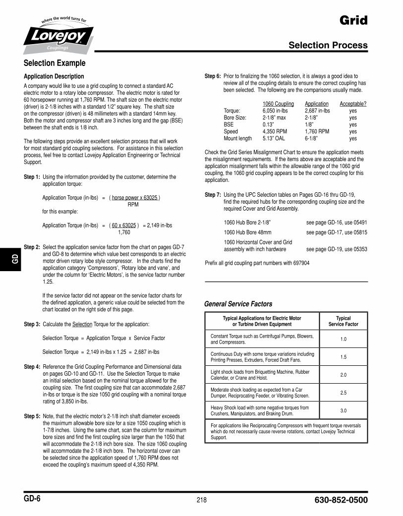
Step 6:■■■Prior■to■finalizing■the■1060■selection,■it■is■always■a■good■idea■to■review■all■of■the■coupling■details■to■ensure■the■correct■coupling■has■been■selected.■■The■following■are■the■comparisons■usually■made.
■ 1060■Coupling■ Application■ Acceptable?Torque:■ 6,050■in-lbs■ 2,687■in-lbs■ yesBore■Size:■ 2-1/8”■max■ 2-1/8”■ yesBSE■ 0.13”■ 1/8”■ yesSpeed■ 4,350■RPM■ 1,760■RPM■ yesMount■length■ 5.13”■OAL■ 6-1/8”■ yes
Check■the■Grid■Series■Misalignment■Chart■to■ensure■the■application■meets■the■misalignment■requirements.■■If■the■items■above■are■acceptable■and■the■application■misalignment■falls■within■the■allowable■range■of■the■1060■grid■coupling,■the■1060■grid■coupling■appears■to■be■the■correct■coupling■for■this■application.
Step 7: ■■Using■the■UPC■Selection■tables■on■Pages■GD-16■thru■GD-19,■find■the■required■hubs■for■the■corresponding■coupling■size■and■the■required■Cover■and■Grid■Assembly.
1060■Hub■Bore■2-1/8”■ see■page■GD-16,■use■05491
1060■Hub■Bore■48mm■ see■page■GD-17,■use■05815
1060■Horizontal■Cover■and■Grid■■assembly■with■inch■hardware■ see■page■GD-19,■use■05353
Prefix■all■grid■coupling■part■numbers■with■697904■
Selection Example
JWJI
SC
JSF
MC
GH
PG
DD
TSP
UJ
VSD
RSL
DED
JWJIS
CJ
SFM
CG
HP
GD
DT
SPU
JVSD
RSLD
ED
Typical Applications for Electric Motor or Turbine Driven Equipment
Typical Service Factor
Constant■Torque■such■as■Centrifugal■Pumps,■Blowers,■and■Compressors. 1.0
Continuous■Duty■with■some■torque■variations■including■Printing■Presses,■Extruders,■Forced■Draft■Fans. 1.5
Light■shock■loads■from■Briquetting■Machine,■Rubber■Calendar,■or■Crane■and■Hoist.■ 2.0
Moderate■shock■loading■as■expected■from■a■Car■Dumper,■Reciprocating■Feeder,■or■Vibrating■Screen. 2.5
Heavy■Shock■load■with■some■negative■torques■from■Crushers,■Manipulators,■and■Braking■Drum.■ 3.0
For■applications■like■Reciprocating■Compressors■with■frequent■torque■reversals■which■do■not■necessarily■cause■reverse■rotations,■contact■Lovejoy■Technical■Support.
General Service Factors

219www.lovejoy-inc.com GD-7
GridApplication Service Factors
Selection Data
Application Service Factors Chart 1
Aggregate Processing, Cement,Mining Kilns; Tube, Rod and Ball Mills■ Dryer,■Rotary,■Hammermill■■ ■ or■Hog,Tumbling■Mill■or■Barrel,■■ ■ Direct■or■on■L.S.■Shaft■of■Red-■ ■ ucer,■with■Final■Drive■of■Single■■ ■ Helical■or■Herringbone■Gears■... 1.75■ 2.75■ 2.25■ Grizzly,■Direct■or■on■L.S.■Shaft■■ ■ of■Reducer,■with■Final■Drive■■ ■ of■Machined■Spur■Gears■........... 2.00■ 3.00■ 2.50■ Crushers,■Ore■or■Stone■............... 2.50■ *■ *Brewing and Distilling■ Bottle■and■Can■Filling■Machines,■■ ■ Brew■Kettle■................................ 1.00■ 2.00■ 1.50■ Cookers,■Continuous■Duty,■■ ■ Mash■Tub■.................................. 1.25■ 2.25■ 1.75■ Lauter■Tub■.................................... 1.50■ 2.50■ 2.00■■ Scale■Hopper,■Frequent■Peaks■... 1.75■ 2.75■ 2.25Clay Working Industry■ Brick■Press,■Briquette■Machine,■■ ■ Clay■Working■Machine,■■ ■ Plug■Mill■..................................... 1.75■ 2.75■ 2.25Dredges■ Conveyors■.................................... 1.25■ 2.25■ 1.75■ Maneuvering■Winch,■Pumps■ ■ (Uniform■Load),■Utility■Winch■.... 1.50■ 2.50■ 2.00■ Cable■Reel,■Screen■Drive,■■ ■ Stacker■...................................... 1.75■ 2.75■ 2.25■ Cutter■Head,■Jig■Drive■................. 2.00■ 3.00■ 2.50Food Industry■ Bottling,■Can■Filling■Machine■....... 1.00■ 2.00■ 1.50■ Cereal■Cooker■.............................. 1.25■ 2.25■ 1.75■■ Beet■Slicer,■Dough■Mixer,■■ ■ Meat■Grinder■............................. 1.75■ 2.75■ 2.25Lumber■ Rolls,■Non-Reversing,■■ ■ Sawdust■Conveyor.................... 1.25■ 2.25■ 1.75■ Band■Resaw,■Sorting■Table■......... 1.50■ 2.50■ 2.00■ Circular■Resaw,■Cut-off,■Planer,■■ ■ Slab■Conveyor,■Trimmer■........... 1.75■ 2.75■ 2.25■ Edger,■Head■Rig,■Hog,■Log■■ ■ Haul,■Rolls,■Reversing■.............. 2.00■ 3.00■ 2.50■ Gang■Saw■(Reciprocating)■................Refer■To■LovejoyMetal Rolling Mills1
■ Soaking■Pit■Cover■Drives■-■Lift■.... 1.00■ 2.00■ 1.50
■ Coilers■(Up■or■Down)■Cold■■ ■ Mills■only,■Cooling■Beds,■Mill■■ ■ Tables■Hot■Bed■or■ Transfer,■Non-Reversing■............. 1.50■ 2.50■ 2.00■ Reel■Drives,■Slitters,■Steel■Mill■■ ■ only,■Wire■Drawing■Machinery■.. 1.75■ 2.75■ 2.25■ Coilers■(Up■or■Down)■Hot■Mills■■ ■ only,■Coke■Plants■Door■■ ■ Opener,■Drawbench,■Furnace■■ ■ Pushers,■Hot■and■Cold■Saws,■ ■ Ingot■Cars,■Mill■Tables■Runout,■■ ■ Non-Reversing,■Non-Plugging,■■ ■ Screwdown,■Seamless■Tube■■ ■ Mills■-Thrust■Block,■Tube■■ ■ Conveyor■Rolls,■Reeler,■Kick■■ ■ Out,■Soaking■Pit■Cover■Drives■■ ■ -■Travel,■Straighteners,■■ Unscramblers■............................... 2.00■ 3.00■ 2.50■ Coke■Plants■Pusher■Ram■■ ■ Drive,■■........................................ 2.50■ *■ *■ Coke■Plants■Pusher■or■Larry■■ ■ Car■Traction■Drive,■Feed■■ ■ Rolls-Blooming■Mills,■Manip-■ ■ ulators,■Mill■Tables■Roughing■ ■ Breakdown■Mills,■Runout,■■ ■ Reversing,■Seamless■Tube■■ ■ Mills■Piercer,■Sideguards■.......... 3.00■ *■ *■ Cold■Mills,■Hot■Mills,■Merchant■■ ■ Mills,■Rod■Mills,■Skelp■Mills■........Refer■To■LovejoyOil Industry■ Chiller■........................................... 1.25■ 2.25■ 1.75■ Paraffin■Filter■Press■..................... 1.50■ 2.50■ 2.00■ Oilwell■Pumping■(not■over■150%■■ ■ Peak■Torque),■Rotary■Kiln■......... 2.00■ 3.00■ 2.50Paper Mills■ Bleachers,■Coaters,■Stock■■ ■ Pumps,■Centrifugal■Constant■■ ■ Speed■........................................ 1.00■ 2.00■ 2.50■ Converting■Machine,■Felt■■ ■ Stretcher,■Stock■Pumps,■■ ■ Centrifugal■Frequent■Speed■■ ■ Changes■Under■Load■............... 1.25■ 2.25■ 1.75■ Line■Shaft,■Reel,■Rewinder,■■ ■ Winder,■Stock■Chest,■Washer,■■ ■ Thickener■.................................. 1.50■ 2.50■ 2.00■ Beater,■Pulper,■Calender,■
■ ■ Couch,■Cylinder,■Dryer,■Pulp■ ■ Grinder,■Fourdrinier,■Press,■ ■ Suction■Roll■............................... 1.75■ 2.75■ 2.25■ Barker■Auxiliary,■Hydraulic,■■ ■ Mechanical,■Barking■Drum■L.S.■■ ■ Shaft■of■Reducer■with■Final■■ ■ Drive-Helical■or■Herringbone■■ ■ Gear,■Cutter,■Felt■Whipper,■■ ■ Jordan,■Log■Haul■...................... 2.00■ 3.00■ 2.50■ Barking■Drum■L.S.■Shaft■of■■ ■ Reducer■with■Final■Drive-■ ■ Machined■Spur■Gear,■Chipper■.. 2.50■ *■ *■ Barking■Drum■L.S.■Shaft■of■■ ■ Reducer■with■Final■Drive-Cast■■ ■ Tooth■Spur■Gear■....................... 3.00■ *■ *Rubber Industry■ Tire/Tube■Press■Opener■(Peak■■ ■ Torque)■...................................... 1.00■ 2.00■ 1.50■ Extruder,■Mixing■Mill,■Refiner■■ ■ or■Sheeter■(Five■or■More■in■■ ■ Line),■Tuber,■Strainer,■Pelletizer,■■ ■ Warming■Mill■(Three■or■More■■ ■ in■Line)■...................................... 1.75■ 2.75■ 2.25■ Calender,■Mixing■Mill,■Refiner■■ ■ or■Sheeter■(Three/Four■in■■ ■ Line),■Warming■Mill■(One/Two■■ ■ in■Line)■...................................... 2.00■ 3.00■ 2.50■ Cracker,■Plasticator,■Mixing■■ ■ Mill,■Refiner■or■Sheeter■■ ■ (One/Two■in■line),■Intensive■■ ■ or■Banbury■Mixer,■Tire■■ ■ Building■Machine,■Washer■........ 2.50■ *■ *Sewage Disposal Equipment■ Bar■Screen,■Chemical■Feeders,■■ ■ Collectors,■Dewatering■■ ■ Screen,■Grit■Collector■............... 1.00■ 2.00■ 1.50Sugar Industry■ Mill■Stands,■Turbine■Driven■with■■ ■ all■Helical■or■Herringbone■■ ■ Gears■........................................ 1.50■ 2.50■ 2.00■ Cane■Carrier■&■Leveler,■Electric■■ ■ Drive■or■Steam■Engine■Drive■■ ■ with■Helical■Herringbone,■or■■ ■ Spur■Gears■with■any■Prime■■ ■ Mover■........................................ 1.75■ 2.75■ 2.25■ Cane■Knife■&■Crusher■.................. 2.00■ 3.00■ 2.50
Elec
tric■
Mot
or■w
/■S
tand
ard■
Torq
ue
Rec
ipro
catin
g■■E
ngin
es-4
/5■C
ylin
der
Rec
ipro
catin
g■■E
ngin
es-6
■or■m
ore■
Cyl
Service Factors
Elec
tric■
Mot
or■w
/■S
tand
ard■
Torq
ue
Rec
ipro
catin
g■■E
ngin
es-4
/5■C
ylin
der
Rec
ipro
catin
g■■E
ngin
es-6
■or■m
ore■
Cyl
Service Factors
Elec
tric■
Mot
or■w
/■S
tand
ard■
Torq
ue
Rec
ipro
catin
g■■E
ngin
es-4
/5■C
ylin
der
Rec
ipro
catin
g■■E
ngin
es-6
■or■m
ore■
Cyl
Service Factors
Notes:■■ n■1■indicates:■For■high■peak■load■applications,■please■refer■to■selection■process■on■page■GD-5.■ n■*■indicates:■That■Lovejoy■Application■Engineering■should■be■consulted■with■specific■requirements.■ n■■Caution:■Applications■involving■reciprocating■engines■and■reciprocating■driven■devices■are■subject■to■critical■rotational■speeds■which■may■damage■the■
coupling■and/or■connected■equipment.■■Contact■Lovejoy■Application■Engineering■with■specific■requirements.
JWJI
SC
JSF
MC
GH
PG
DD
TSP
UJ
VSD
RSL
DED
JWJIS
CJ
SFM
CG
HP
GD
DT
SPU
JVSD
RSLD
ED
220 630-852-0500GD-8
GridApplication Service Factors
Selection Data
Application Service Factors Chart 1, Continued
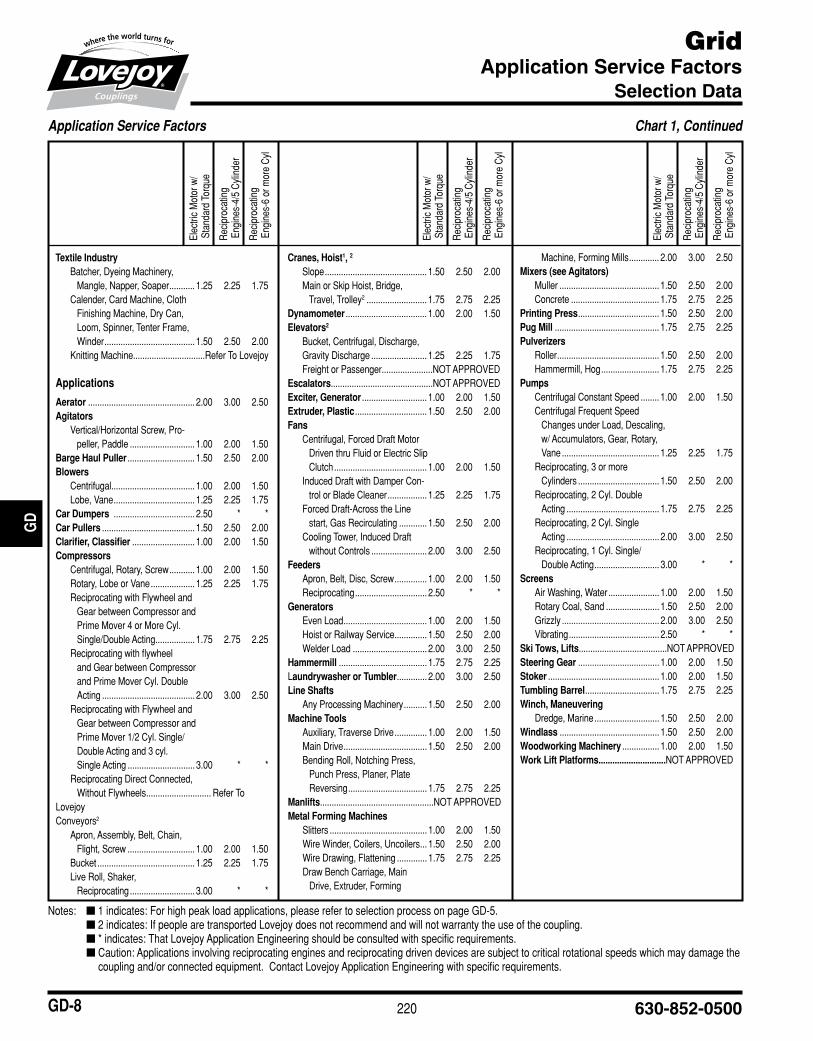
Textile Industry■ Batcher,■Dyeing■Machinery,■■ ■ Mangle,■Napper,■Soaper■........... 1.25■ 2.25■ 1.75■ Calender,■Card■Machine,■Cloth■■ ■ Finishing■Machine,■Dry■Can,■■ ■ Loom,■Spinner,■Tenter■Frame,■■ ■ Winder■....................................... 1.50■ 2.50■ 2.00■ Knitting■Machine...............................■Refer■To■Lovejoy
Applications
Aerator■.............................................. 2.00■ 3.00■ 2.50Agitators■ Vertical/Horizontal■Screw,■Pro-■ ■ peller,■Paddle■............................ 1.00■ 2.00■ 1.50Barge Haul Puller■............................. 1.50■ 2.50■ 2.00Blowers■ Centrifugal■.................................... 1.00■ 2.00■ 1.50■ Lobe,■Vane■................................... 1.25■ 2.25■ 1.75Car Dumpers ■................................... 2.50■ *■ *Car Pullers■........................................ 1.50■ 2.50■ 2.00Clarifier, Classifier■........................... 1.00■ 2.00■ 1.50Compressors■ Centrifugal,■Rotary,■Screw■........... 1.00■ 2.00■ 1.50■ Rotary,■Lobe■or■Vane■................... 1.25■ 2.25■ 1.75■ Reciprocating■with■Flywheel■and■■ ■ Gear■between■Compressor■and■■ ■ Prime■Mover■4■or■More■Cyl.■■ ■ Single/Double■Acting■................. 1.75■ 2.75■ 2.25■ Reciprocating■with■flywheel■■ ■ and■Gear■between■Compressor■■ ■ and■Prime■Mover■Cyl.■Double■■ ■ Acting■........................................ 2.00■ 3.00■ 2.50■ Reciprocating■with■Flywheel■and■■ ■ Gear■between■Compressor■and■■ ■ Prime■Mover■1/2■Cyl.■Single/■ ■ Double■Acting■and■3■cyl.■■ ■ Single■Acting■............................. 3.00■ *■ *■ Reciprocating■Direct■Connected,■■ ■ Without■Flywheels■............................ ■Refer■To■Lovejoy■Conveyors2
■ Apron,■Assembly,■Belt,■Chain,■■ ■ Flight,■Screw■............................. 1.00■ 2.00■ 1.50■ Bucket■.......................................... 1.25■ 2.25■ 1.75■ Live■Roll,■Shaker,■■ ■ Reciprocating■............................ 3.00■ *■ *
Cranes, Hoist1, 2
■ Slope■............................................ 1.50■ 2.50■ 2.00■ Main■or■Skip■Hoist,■Bridge,■■ ■ Travel,■Trolley2■.......................... 1.75■ 2.75■ 2.25Dynamometer■................................... 1.00■ 2.00■ 1.50Elevators2
■ Bucket,■Centrifugal,■Discharge,■■ Gravity■Discharge■........................ 1.25■ 2.25■ 1.75■ Freight■or■Passenger■......................NOT■APPROVEDEscalators............................................NOT■APPROVEDExciter, Generator■............................ 1.00■ 2.00■ 1.50Extruder, Plastic■............................... 1.50■ 2.50■ 2.00Fans■ Centrifugal,■Forced■Draft■Motor■■ ■ Driven■thru■Fluid■or■Electric■Slip■■ ■ Clutch■........................................ 1.00■ 2.00■ 1.50■ Induced■Draft■with■Damper■Con-■■ ■ trol■or■Blade■Cleaner■................. 1.25■ 2.25■ 1.75■ Forced■Draft-Across■the■Line■■ ■ start,■Gas■Recirculating■............ 1.50■ 2.50■ 2.00■ Cooling■Tower,■Induced■Draft■■ ■ without■Controls■........................ 2.00■ 3.00■ 2.50Feeders■ Apron,■Belt,■Disc,■Screw■.............. 1.00■ 2.00■ 1.50■ Reciprocating■............................... 2.50■ *■ *Generators■ Even■Load■.................................... 1.00■ 2.00■ 1.50■ Hoist■or■Railway■Service■.............. 1.50■ 2.50■ 2.00■ Welder■Load■................................ 2.00■ 3.00■ 2.50Hammermill■...................................... 1.75■ 2.75■ 2.25Laundrywasher or Tumbler■............. 2.00■ 3.00■ 2.50Line Shafts■ Any■Processing■Machinery■.......... 1.50■ 2.50■ 2.00Machine Tools■ Auxiliary,■Traverse■Drive■.............. 1.00■ 2.00■ 1.50■ Main■Drive■.................................... 1.50■ 2.50■ 2.00■ Bending■Roll,■Notching■Press,■■ ■ Punch■Press,■Planer,■Plate■■ ■ Reversing■.................................. 1.75■ 2.75■ 2.25Manlifts.................................................NOT■APPROVEDMetal Forming Machines■ Slitters■.......................................... 1.00■ 2.00■ 1.50■ Wire■Winder,■Coilers,■Uncoilers■... 1.50■ 2.50■ 2.00■ Wire■Drawing,■Flattening■............. 1.75■ 2.75■ 2.25■ Draw■Bench■Carriage,■Main■■ ■ Drive,■Extruder,■Forming■
■ ■ Machine,■Forming■Mills■............. 2.00■ 3.00■ 2.50Mixers (see Agitators)■ Muller■........................................... 1.50■ 2.50■ 2.00■ Concrete■...................................... 1.75■ 2.75■ 2.25Printing Press■................................... 1.50■ 2.50■ 2.00Pug Mill■............................................. 1.75■ 2.75■ 2.25Pulverizers■ Roller■............................................ 1.50■ 2.50■ 2.00■ Hammermill,■Hog■......................... 1.75■ 2.75■ 2.25Pumps■ Centrifugal■Constant■Speed■........ 1.00■ 2.00■ 1.50■ Centrifugal■Frequent■Speed■■ ■ Changes■under■Load,■Descaling,■■ ■ w/■Accumulators,■Gear,■Rotary,■■ ■ Vane■.......................................... 1.25■ 2.25■ 1.75■ Reciprocating,■3■or■more■■ ■ Cylinders■................................... 1.50■ 2.50■ 2.00■ Reciprocating,■2■Cyl.■Double■■ ■ Acting■........................................ 1.75■ 2.75■ 2.25■ Reciprocating,■2■Cyl.■Single■■ ■ Acting■........................................ 2.00■ 3.00■ 2.50■ Reciprocating,■1■Cyl.■Single/■ ■ Double■Acting■............................ 3.00■ *■ *Screens■ Air■Washing,■Water■...................... 1.00■ 2.00■ 1.50■ Rotary■Coal,■Sand■....................... 1.50■ 2.50■ 2.00■ Grizzly■.......................................... 2.00■ 3.00■ 2.50■ Vibrating■....................................... 2.50■ *■ *Ski Tows, Lifts......................................NOT■APPROVEDSteering Gear■................................... 1.00■ 2.00■ 1.50Stoker■................................................ 1.00■ 2.00■ 1.50Tumbling Barrel■................................ 1.75■ 2.75■ 2.25Winch, Maneuvering■ Dredge,■Marine■............................ 1.50■ 2.50■ 2.00■Windlass■........................................... 1.50■ 2.50■ 2.00Woodworking Machinery■................ 1.00■ 2.00■ 1.50Work Lift Platforms.............................NOT■APPROVED
Elec
tric■
Mot
or■w
/■S
tand
ard■
Torq
ue
Rec
ipro
catin
g■■E
ngin
es-4
/5■C
ylin
der
Rec
ipro
catin
g■■E
ngin
es-6
■or■m
ore■
Cyl
Elec
tric■
Mot
or■w
/■S
tand
ard■
Torq
ue
Rec
ipro
catin
g■■E
ngin
es-4
/5■C
ylin
der
Rec
ipro
catin
g■■E
ngin
es-6
■or■m
ore■
Cyl
Elec
tric■
Mot
or■w
/■S
tand
ard■
Torq
ue
Rec
ipro
catin
g■■E
ngin
es-4
/5■C
ylin
der
Rec
ipro
catin
g■■E
ngin
es-6
■or■m
ore■
Cyl
Notes:■■ n■1■indicates:■For■high■peak■load■applications,■please■refer■to■selection■process■on■page■GD-5.■ n■2■indicates:■If■people■are■transported■Lovejoy■does■not■recommend■and■will■not■warranty■the■use■of■the■coupling.■ n■*■indicates:■That■Lovejoy■Application■Engineering■should■be■consulted■with■specific■requirements.■ n■■Caution:■Applications■involving■reciprocating■engines■and■reciprocating■driven■devices■are■subject■to■critical■rotational■speeds■which■may■damage■the■
coupling■and/or■connected■equipment.■■Contact■Lovejoy■Application■Engineering■with■specific■requirements.
JWJI
SC
JSF
MC
GH
PG
DD
TSP
UJ
VSD
RSL
DED
JWJIS
CJ
SFM
CG
HP
GD
DT
SPU
JVSD
RSLD
ED
221www.lovejoy-inc.com GD-9
Grid
Grid Coupling Selection Worksheet
JWJI
SC
JSF
MC
GH
PG
DD
TSP
UJ
VSD
RSL
DED
JWJIS
CJ
SFM
CG
HP
GD
DT
SPU
JVSD
RSLD
ED
Customer Name: _______________________________________ Contact Name: _________________________________________________________
Phone Number:_________________________________________ Email Address: _________________________________________________________
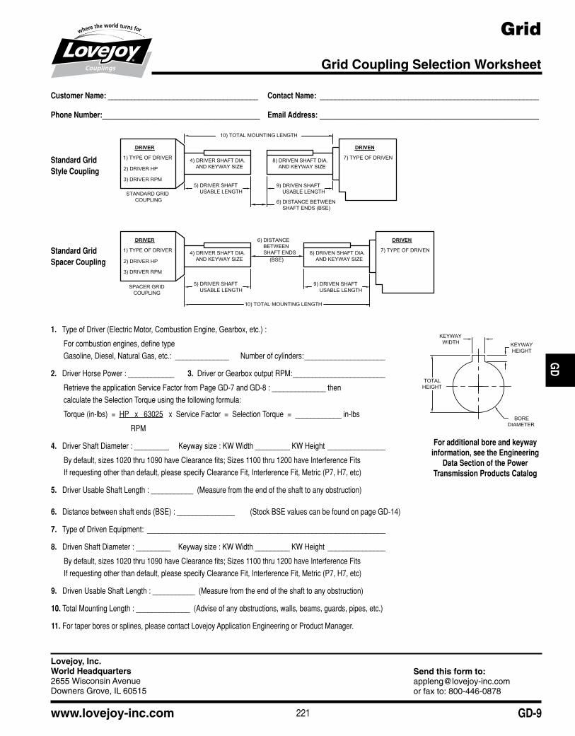
Standard Grid Style Coupling
Standard Grid Spacer Coupling
1.■ Type■of■Driver■(Electric■Motor,■Combustion■Engine,■Gearbox,■etc.)■:
For■combustion■engines,■define■typeGasoline,■Diesel,■Natural■Gas,■etc.:■■______________■■■■■■Number■of■cylinders:■_____________________
2.■ Driver■Horse■Power■:■____________■■■■■■■3.■■Driver■or■Gearbox■output■RPM:■________________________
Retrieve■the■application■Service■Factor■from■Page■GD-7■and■GD-8■:■______________■thencalculate■the■Selection■Torque■using■the■following■formula:
Torque■(in-lbs)■■=■■HP■■■x■■■63025■■■x■■Service■Factor■■=■■Selection■Torque■■=■■____________■in-lbs
■■■■■■■■■■■■■■■■■■■■■■■■■■■■■■■■■■■RPM
4.■ Driver■Shaft■Diameter■:■_________■■■■■Keyway■size■:■KW■Width■_________■KW■Height■_______________
By■default,■sizes■1020■thru■1090■have■Clearance■fits;■Sizes■1100■thru■1200■have■Interference■FitsIf■requesting■other■than■default,■please■specify■Clearance■Fit,■Interference■Fit,■Metric■(P7,■H7,■etc)
5.■ Driver■Usable■Shaft■Length■:■___________■■(Measure■from■the■end■of■the■shaft■to■any■obstruction)
6.■ Distance■between■shaft■ends■(BSE)■:■_______________■■■■■■■■(Stock■BSE■values■can■be■found■on■page■GD-14)
7.■ Type■of■Driven■Equipment:■ ______________________________________________________________
8.■ Driven■Shaft■Diameter■:■_________■■■■Keyway■size■:■KW■Width■_________■KW■Height■ _______________
By■default,■sizes■1020■thru■1090■have■Clearance■fits;■Sizes■1100■thru■1200■have■Interference■FitsIf■requesting■other■than■default,■please■specify■Clearance■Fit,■Interference■Fit,■Metric■(P7,■H7,■etc)
9.■ Driven■Usable■Shaft■Length■:■___________■■(Measure■from■the■end■of■the■shaft■to■any■obstruction)
10.■Total■Mounting■Length■:■______________■■(Advise■of■any■obstructions,■walls,■beams,■guards,■pipes,■etc.)
11.■For■taper■bores■or■splines,■please■contact■Lovejoy■Application■Engineering■or■Product■Manager.
For additional bore and keyway information, see the Engineering
Data Section of the Power Transmission Products Catalog
Lovejoy, Inc.World Headquarters2655 Wisconsin AvenueDowners Grove, IL 60515
Send this form to:[email protected] fax to: 800-446-0878

222 630-852-0500GD-10
Grid Standard Coupling
Performance Data
Notes:■■ n■■1■Indicates:■■Peak■torque■is■typically■twice■the■Nominal■Torque■value.■ n■■■2■Indicates:■■Sizes■1020■thru■1090■are■bored■with■clearance■fit■with■2■set■screws■at■90º,■sizes■1100■and■larger■are■bored■with■interference■fit■and■
no■set■screw.
Standard Grid Style Couplings Horizontal and Vertical Cover
The■Lovejoy■Grid■coupling■is■an■ideal■coupling■for■applications■where■excellent■performance■is■desired■and■additional■requirements■for■vibration■dampening■may■exist.■■The■Horizontal■Split■Cover■design■is■recommended■in■applications■where■there■may■be■some■constraints■on■the■diameter■of■the■coupling.■■The■vertical■design■is■recommended■for■applications■where■higher■speed■is■one■of■the■requirements.
Features:■■ Designed■for■ease■of■maintenance■and■grid■spring■replacement
■■ High■tensile■grid■springs■ensure■superior■coupling■performance■and■longer■coupling■life
■■ Split■covers■allow■for■easy■access■to■grid■springs■
■■ Interchangeable■with■industry■standard■grid■couplings
JWJI
SC
JSF
MC
GH
PG
DD
TSP
UJ
VSD
RSL
DED
JWJIS
CJ
SFM
CG
HP
GD
DT
SPU
JVSD
RSLD
ED
Horizontal Cover Style
Vertical Cover Style
Grid Coupling Performance Data
Nominal Maximum ID1 - ID2 SL2 T Weight Moment of Inertia
Torque1 Speed Min Bore Max Bore Set Screw Solid Solid Hubs
Horizontal Vertical Location Size Horizontal Vertical
Size in-lbs Nm RPM RPM in mm in mm in in lbs kg WR2 lb-in2 WR2 lb-in2
1020 460 52 4,500 6,000 0.500 12 1.125 28 0.50 #8-32 4.3 2.0 4.83 5.32
1030 1,320 149 4,500 6,000 0.500 12 1.375 35 0.31 #8-32 5.7 2.6 7.61 7.99
1040 2,200 249 4,500 6,000 0.500 12 1.625 42 0.44 #10-24 7.4 3.4 11.19 11.99
1050 3,850 435 4,500 6,000 0.500 12 1.875 48 0.62 #10-24 12.0 5.4 24.85 25.76
1060 6,050 983 4,350 6,000 0.750 19 2.125 54 0.44 #10-24 16.0 7.3 40.66 41.16
1070 8,800 994 4,125 5,500 0.750 19 2.500 64 0.88 1/4-20 23.0 10.4 63.18 61.68
1080 18,150 2■051 3,600 4,750 1.062 27 3.000 76 0.94 1/4-20 39.0 17.7 154.00 148.00
1090 33,000 3■728 3,600 4,000 1.062 27 3.500 89 1.03 5/16-18 56.0 25.4 269.00 272.00
1100 55,550 6■276 2,400 3,250 1.625 41 4.000 102 — — 93.0 42.2 609.00 608.00
1110 82,500 9■321 2,250 3,000 1.625 41 4.500 117 — — 120.0 54.4 923.00 930.00
1120 121,000 13■671 2,025 2,700 2.375 60 5.000 127 — — 180.0 81.2 1,755.00 1,611.00
1130 176,000 19■884 1,800 2,400 2.625 67 6.000 152 — — 270.0 121.0 3,375.00 3,568.00
1140 253,000 28■584 1,650 2,200 2.625 67 7.250 184 — — 394.0 177.8 6,306.00 6,431.00
1150 352,000 39■769 1,500 — 4.250 108 8.000 200 — — 523.0 237.2 — —
1160 495,000 55■925 1,350 — 4.750 121 9.000 228 — — 720.0 326.5 — —
1170 660,000 74■567 1,225 — 5.250 134 10.000 254 — — 1,022.5 463.7 — —
1180 915,200 103■399 1,100 — 6.000 153 11.000 280 — — 1,341.7 608.5 — —
1190 1,210,000 136■706 1,050 — 6.000 153 12.000 305 — — 1,710.0 775.5 — —
1200 1,650,000 186■417 900 — 7.000 178 13.000 330 — — 2,331.0 1057.1 — —

223www.lovejoy-inc.com GD-11
GridStandard Coupling
Dimensional Data
Note:■■ n■■1■indicates:■For■sizes■1020■thru■1080,■the■gap■tolerance■for■dimension■G■is■+■.050"■/■-■.050"■(+■1.5■mm■/■-■1.5■mm).For■sizes■1090■thru■1120,■the■gap■tolerance■for■dimension■G■is■+■.177"■/■-■.118"■(+■4.5■mm■/■-■3■mm).■For■sizes■1120■thru■1200,■the■gap■tolerance■for■dimension■G■is■+■.236"■/■-■.177"■(+■6■mm■/■-■4.5■mm).
JWJI
SC
JSF
MC
GH
PG
DD
TSP
UJ
VSD
RSL
DED
JWJIS
CJ
SFM
CG
HP
GD
DT
SPU
JVSD
RSLD
ED
Grid Coupling with Horizontal Style Cover
Sizes 1020 - 1140 Sizes 1150 - 1200 Sizes 1020 - 1090
Grid Coupling with Vertical Style Cover
Grid Coupling Dimensional Data
OAL R L FL G 1 LTB OD FD HD
Horz Vert Horz Vert
Cover Cover Cover Cover
Size in mm in in in in in mm in mm in mm in mm in mm in mm
1020 3.88 98.5 1.88 2.62 0.96 0.38 0.118 3.00 1.87 47.5 4.00 101.6 4.38 111.3 2.50 63.5 1.56 39.7
1030 3.88 98.5 1.88 2.69 1.00 0.38 0.118 3.00 1.87 47.5 4.33 110.0 4.75 120.7 2.88 73.0 1.94 49.2
1040 4.12 104.7 2.00 2.75 1.03 0.38 0.118 3.00 2.00 50.8 4.63 117.6 5.06 128.5 3.25 82.6 2.25 57.2
1050 4.88 123.8 2.38 3.18 1.24 0.47 0.118 3.00 2.37 60.3 5.43 138.0 5.81 147.6 3.88 98.4 2.63 66.7
1060 5.12 130.0 2.50 3.68 1.27 0.50 0.118 3.00 2.50 63.5 5.93 150.5 6.38 162.1 4.38 111.1 3.00 76.2
1070 6.12 155.5 2.63 3.80 1.33 0.50 0.118 3.00 3.00 76.2 6.37 161.8 6.81 173.0 4.88 123.8 3.44 87.3
1080 7.12 180.8 3.50 4.55 1.74 0.50 0.118 3.00 3.50 88.9 7.64 194.0 7.13 181.1 5.00 127.0 4.13 104.9
1090 7.88 200.0 3.75 4.80 1.86 0.50 0.118 3.00 3.87 98.4 8.39 213.0 7.88 200.2 5.88 149.2 4.87 123.7
1100 9.69 246.1 4.75 6.12 2.38 0.63 0.177 4.50 4.75 120.6 9.84 250.0 9.69 246.1 7.75 196.9 5.59 142.0
1110 10.19 258.7 4.88 6.36 2.50 0.63 0.177 4.50 5.00 127.0 10.63 270.0 11.25 285.8 8.50 215.9 6.31 160.3
1120 12.00 304.8 5.63 7.54 2.94 0.68 0.236 6.00 5.87 149.2 12.13 308.0 12.56 319.0 9.63 244.5 7.06 179.4
1130 13.00 330.2 5.75 7.68 3.00 0.82 0.236 6.00 6.37 161.9 13.62 346.0 14.88 378.0 11.13 282.6 8.56 217.5
1140 14.63 371.6 6.13 7.91 3.13 0.82 0.236 6.00 7.20 182.9 15.12 384.0 16.38 416.1 12.63 320.7 10.00 254.0
1150 14.65 372.1 — 10.69 — — 0.236 6.00 7.20 182.9 17.84 453.1 — — — — 10.60 269.2
1160 15.85 402.6 — 10.96 — — 0.236 6.00 7.80 198.1 19.74 501.4 — — — — 12.00 304.8
1170 17.25 437.1 — 12.10 — — 0.236 6.00 8.50 215.9 22.30 566.4 — — — — 14.00 355.6
1180 19.05 483.9 — 12.64 — — 0.236 6.00 9.40 238.8 24.80 629.9 — — — — 15.50 393.7
1190 20.65 524.5 — 12.80 — — 0.236 6.00 10.20 259.1 26.60 675.6 — — — — 17.20 436.9
1200 22.25 565.1 — 14.00 — — 0.236 6.00 10.98 279.0 29.80 756.9 — — — — 19.60 497.8
224 630-852-0500GD-12
GridSpacer Style
Performance / Dimensional Data
Note:■■ n■1■Indicates:■■Peak■torque■is■typically■twice■the■Nominal■Torque■value.
JWJI
SC
JSF
MC
GH
PG
DD
TSP
UJ
VSD
RSL
DED
JWJIS
CJ
SFM
CG
HP
GD
DT
SPU
JVSD
RSLD
ED
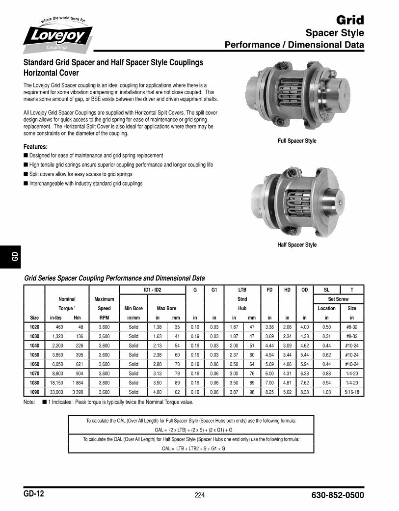
Standard Grid Spacer and Half Spacer Style Couplings Horizontal CoverThe■Lovejoy■Grid■Spacer■coupling■is■an■ideal■coupling■for■applications■where■there■is■a■requirement■for■some■vibration■dampening■in■installations■that■are■not■close■coupled.■■This■means■some■amount■of■gap,■or■BSE■exists■between■the■driver■and■driven■equipment■shafts.■
All■Lovejoy■Grid■Spacer■Couplings■are■supplied■with■Horizontal■Split■Covers.■The■split■cover■design■allows■for■quick■access■to■the■grid■spring■for■ease■of■maintenance■or■grid■spring■replacement.■■The■Horizontal■Split■Cover■is■also■ideal■for■applications■where■there■may■be■some■constraints■on■the■diameter■of■the■coupling.■■
Features:■■ Designed■for■ease■of■maintenance■and■grid■spring■replacement
■■ High■tensile■grid■springs■ensure■superior■coupling■performance■and■longer■coupling■life
■■ Split■covers■allow■for■easy■access■to■grid■springs■
■■ Interchangeable■with■industry■standard■grid■couplings
Full Spacer Style
Half Spacer Style
Grid Series Spacer Coupling Performance and Dimensional Data
ID1 - ID2 G G1 LTB FD HD OD SL T
Nominal Maximum Stnd Set Screw
Torque 1 Speed Min Bore Max Bore Hub Location Size
Size in-lbs Nm RPM in/mm in mm in in in mm in in in in in
1020 460 48 3,600 Solid 1.38 35 0.19 0.03 1.87 47 3.38 2.06 4.00 0.50 #8-32
1030 1,320 136 3,600 Solid 1.63 41 0.19 0.03 1.87 47 3.69 2.34 4.38 0.31 #8-32
1040 2,200 226 3,600 Solid 2.13 54 0.19 0.03 2.00 51 4.44 3.09 4.62 0.44 #10-24
1050 3,850 395 3,600 Solid 2.38 60 0.19 0.03 2.37 60 4.94 3.44 5.44 0.62 #10-24
1060 6,050 621 3,600 Solid 2.88 73 0.19 0.06 2.50 64 5.69 4.06 5.94 0.44 #10-24
1070 8,800 904 3,600 Solid 3.13 79 0.19 0.06 3.00 76 6.00 4.31 6.38 0.88 1/4-20
1080 18,150 1■864 3,600 Solid 3.50 89 0.19 0.06 3.50 89 7.00 4.81 7.62 0.94 1/4-20
1090 33,000 3■390 3,600 Solid 4.00 102 0.19 0.06 3.87 98 8.25 5.62 8.38 1.03 5/16-18
To■calculate■the■OAL■(Over■All■Length)■for■Full■Spacer■Style■(Spacer■Hubs■both■ends)■use■the■following■formula:
■■■■OAL■=■■(2■x■LTB)■+■(2■x■S)■+■(2■x■G1)■+■G
To■calculate■the■OAL■(Over■All■Length)■for■Half■Spacer■Style■(Spacer■Hubs■one■end■only)■use■the■following■formula:
■■■■OAL■=■■LTB■+■LTB2■+■S■+■G1■+■G
225www.lovejoy-inc.com GD-13
GridSpacer Style
Spacer Hub Selection
JWJI
SC
JSF
MC
GH
PG
DD
TSP
UJ
VSD
RSL
DED
JWJIS
CJ
SFM
CG
HP
GD
DT
SPU
JVSD
RSLD
ED
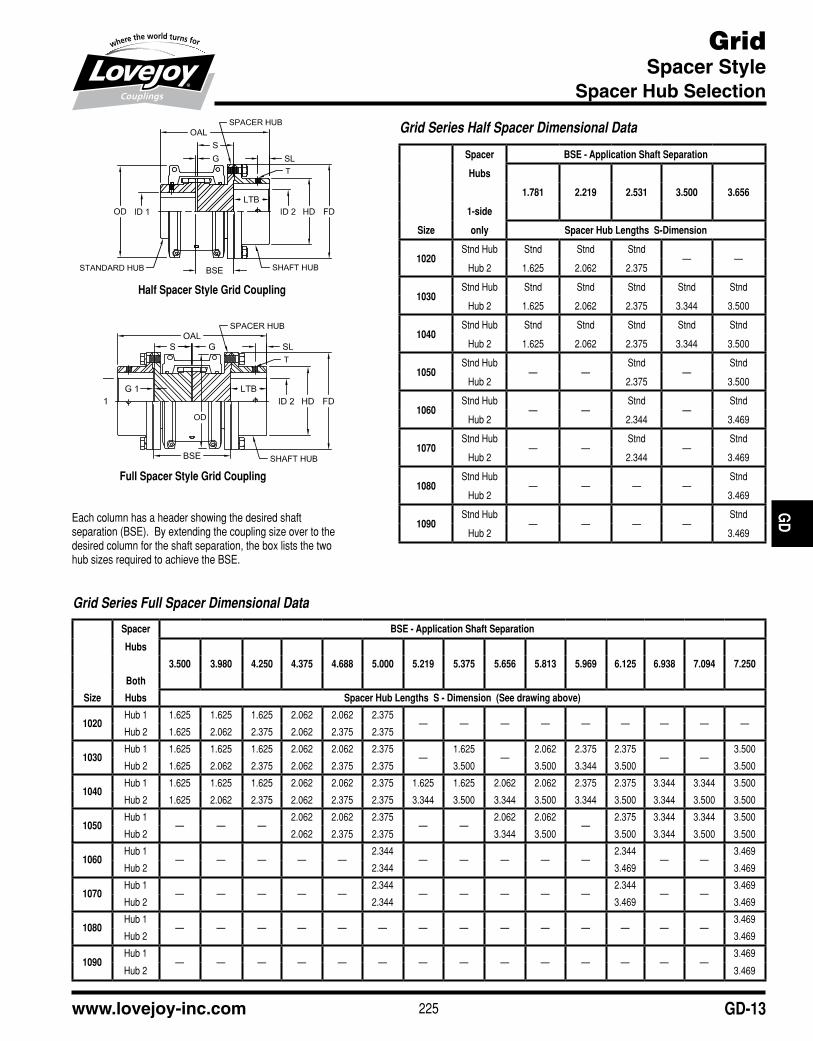
Full Spacer Style Grid Coupling
Each■column■has■a■header■showing■the■desired■shaft■separation■(BSE).■■By■extending■the■coupling■size■over■to■the■desired■column■for■the■shaft■separation,■the■box■lists■the■two■hub■sizes■required■to■achieve■the■BSE.
Grid Series Full Spacer Dimensional Data
Spacer BSE - Application Shaft Separation
Hubs
3.500 3.980 4.250 4.375 4.688 5.000 5.219 5.375 5.656 5.813 5.969 6.125 6.938 7.094 7.250
Both
Size Hubs Spacer Hub Lengths S - Dimension (See drawing above)
1020Hub■1 1.625 1.625 1.625 2.062 2.062 2.375
— — — — — — — — —Hub■2 1.625 2.062 2.375 2.062 2.375 2.375
1030Hub■1 1.625 1.625 1.625 2.062 2.062 2.375
—1.625
—2.062 2.375 2.375
— —3.500
Hub■2 1.625 2.062 2.375 2.062 2.375 2.375 3.500 3.500 3.344 3.500 3.500
1040Hub■1 1.625 1.625 1.625 2.062 2.062 2.375 1.625 1.625 2.062 2.062 2.375 2.375 3.344 3.344 3.500
Hub■2 1.625 2.062 2.375 2.062 2.375 2.375 3.344 3.500 3.344 3.500 3.344 3.500 3.344 3.500 3.500
1050Hub■1
— — —2.062 2.062 2.375
— —2.062 2.062
—2.375 3.344 3.344 3.500
Hub■2 2.062 2.375 2.375 3.344 3.500 3.500 3.344 3.500 3.500
1060Hub■1
— — — — —2.344
— — — — —2.344
— —3.469
Hub■2 2.344 3.469 3.469
1070Hub■1
— — — — —2.344
— — — — —2.344
— —3.469
Hub■2 2.344 3.469 3.469
1080Hub■1
— — — — — — — — — — — — — —3.469
Hub■2 3.469
1090Hub■1
— — — — — — — — — — — — — —3.469
Hub■2 3.469
Grid Series Half Spacer Dimensional Data
Spacer BSE - Application Shaft Separation
Hubs
1.781 2.219 2.531 3.500 3.656
1-side
Size only Spacer Hub Lengths S-Dimension
1020Stnd■Hub Stnd Stnd Stnd
— —Hub■2 1.625 2.062 2.375
1030Stnd■Hub Stnd Stnd Stnd Stnd Stnd
Hub■2 1.625 2.062 2.375 3.344 3.500
1040Stnd■Hub Stnd Stnd Stnd Stnd Stnd
Hub■2 1.625 2.062 2.375 3.344 3.500
1050Stnd■Hub
— —Stnd
—Stnd
Hub■2 2.375 3.500
1060Stnd■Hub
— —Stnd
—Stnd
Hub■2 2.344 3.469
1070Stnd■Hub
— —Stnd
—Stnd
Hub■2 2.344 3.469
1080Stnd■Hub
— — — —Stnd
Hub■2 3.469
1090Stnd■Hub
— — — —Stnd
Hub■2 3.469
Half Spacer Style Grid Coupling
226 630-852-0500GD-14
GridMisalignment Capability
Item Selection
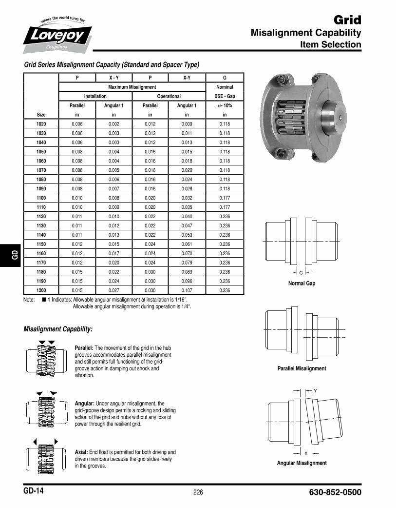
Misalignment Capability:
Parallel: The■movement■of■the■grid■in■the■hub■grooves■accommodates■parallel■misalignment■and■still■permits■full■functioning■of■the■grid-groove■action■in■damping■out■shock■and■vibration.
Angular: Under■angular■misalignment,■the■grid-groove■design■permits■a■rocking■and■sliding■action■of■the■grid■and■hubs■without■any■loss■of■power■through■the■resilient■grid.
Axial:■End■float■is■permitted■for■both■driving■and■driven■members■because■the■grid■slides■freely■in■the■grooves.■■
Normal Gap
Angular Misalignment
Parallel Misalignment
JWJI
SC
JSF
MC
GH
PG
DD
TSP
UJ
VSD
RSL
DED
JWJIS
CJ
SFM
CG
HP
GD
DT
SPU
JVSD
RSLD
ED
Grid Series Misalignment Capacity (Standard and Spacer Type)
P X - Y P X-Y G
Maximum Misalignment Nominal
Installation Operational BSE - Gap
Parallel Angular 1 Parallel Angular 1 +/- 10%
Size in in in in in
1020 0.006 0.002 0.012 0.009 0.118
1030 0.006 0.003 0.012 0.011 0.118
1040 0.006 0.003 0.012 0.013 0.118
1050 0.008 0.004 0.016 0.015 0.118
1060 0.008 0.004 0.016 0.018 0.118
1070 0.008 0.005 0.016 0.020 0.118
1080 0.008 0.006 0.016 0.024 0.118
1090 0.008 0.007 0.016 0.028 0.118
1100 0.010 0.008 0.020 0.032 0.177
1110 0.010 0.009 0.020 0.035 0.177
1120 0.011 0.010 0.022 0.040 0.236
1130 0.011 0.012 0.022 0.047 0.236
1140 0.011 0.013 0.022 0.053 0.236
1150 0.012 0.015 0.024 0.061 0.236
1160 0.012 0.017 0.024 0.070 0.236
1170 0.012 0.020 0.024 0.079 0.236
1180 0.015 0.022 0.030 0.089 0.236
1190 0.015 0.024 0.030 0.096 0.236
1200 0.015 0.027 0.030 0.107 0.236
Note:■■ n■1■Indicates:■Allowable■angular■misalignment■at■installation■is■1/16°.Allowable■angular■misalignment■during■operation■is■1/4°.

227www.lovejoy-inc.com GD-15
GridIndustry Standard Interchange Chart
Item Selection
Industry Standard InterchangeLovejoy■Grid■couplings■are■interchangeable■with■industry■standard■grid■couplings■supplied■by■other■major■coupling■manufacturers.■■The■chart■below■provides■part■numbers■necessary■to■make■the■crossover■from■these■other■major■manufacturers.
JWJI
SC
JSF
MC
GH
PG
DD
TSP
UJ
VSD
RSL
DED
JWJIS
CJ
SFM
CG
HP
GD
DT
SPU
JVSD
RSLD
ED
Industry Standard Grid Coupling Interchange Chart
Lovejoy® Size
Horizontal — Split Cover Vertical — Split Cover
Falk® Steelflex®
Morse/Browning® Grid-Flex®
Dodge® Grid-Lign®
Kop-Flex® Kop-Grid®
Falk® Steelflex®
Morse/Browning® Grid-Flex®
Dodge® Grid-Lign®
Kop-Flex® Kop-Grid®
1020 1020T10 GF2020H 1020T10 1020H 1020T20 GF2020V 1020T20 1020V
1030 1030T10 GF2030H 1030T10 1030H 1030T20 GF2030V 1030T20 1030V
1040 1040T10 GF2040H 1040T10 1040H 1040T20 GF2040V 1040T20 1040V
1050 1050T10 GF2050H 1050T10 1050H 1050T20 GF2050V 1050T20 1050V
1060 1060T10 GF2060H 1060T10 1060H 1060T20 GF2060V 1060T20 1060V
1070 1070T10 GF2070H 1070T10 1070H 1070T20 GF2070V 1070T20 1070V
1080 1080T10 GF2080H 1080T10 1080H 1080T20 GF2080V 1080T20 1080V
1090 1090T10 GF2090H 1090T10 1090H 1090T20 GF2090V 1090T20 1090V
1100 1100T10 GF2100H 1100T10 1100H 1100T20 GF2100V 1100T20 1100V
1110 1110T10 GF2110H 1110T10 1110H 1110T20 GF2110V 1110T20 1110V
1120 1120T10 GF2120H 1120T10 1120H 1120T20 GF2120V 1120T20 1120V
1130 1130T10 GF2130H 1130T10 1130H 1130T20 GF2130V 1130T20 1130V
1140 1140T10 GF2140H 1140T10 1140H 1140T20 GF2140V 1140T20 1140V
1150 1150T10 — — — — — — —
1160 1160T10 — — — — — — —
1170 1170T10 — — — — — — —
1180 1180T10 — — — — — — —
1190 1190T10 — — — — — — —
1200 1200T10 — — — — — — —
228 630-852-0500GD-16
GridGrid Coupling Hubs – Inch Bore / Keyway
Item Selection
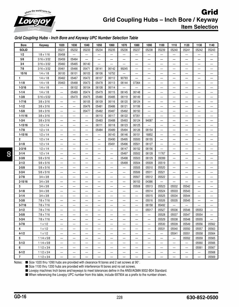
Notes:■■ n Size■1020■thru■1090■hubs■are■provided■with■clearance■fit■bores■and■2■set■screws■at■90°.■ n■■Size■1100■thru■1200■hubs■are■provided■with■interference■fit■bores■and■no■set■screws.■ n■Lovejoy■machines■Inch■bores■and■keyways■to■meet■tolerances■define■in■the■ANSI/AGMA■9002-B04■Standard.■ n■When■referencing■the■Lovejoy■UPC■number■from■this■table,■include■697904■as■a■prefix■to■the■number■shown.
JWJI
SC
JSF
MC
GH
PG
DD
TSP
UJ
VSD
RSL
DED
JWJIS
CJ
SFM
CG
HP
GD
DT
SPU
JVSD
RSLD
ED
Grid Coupling Hubs - Inch Bore and Keyway UPC Number Selection Table
Bore Keyway 1020 1030 1040 1050 1060 1070 1080 1090 1100 1110 1120 1130 1140
SOLID 05231 05232 05233 05234 05235 05236 05237 05238 05239 05240 05241 05242 05243
1/2 1/8■x■1/16 05458 — — — — — — — — — — — —
5/8 3/16■x■3/32 05459 05464 — — — — — — — — — — —
3/4 3/16■x■3/32 05460 05465 06140 — — — — — — — — — —
7/8 3/16■x■3/32 05461 05466 05471 06141 06142 99245 — — — — — — —
15/16 1/4■x■1/8 06100 06101 06103 06106 16752 — — — — — — — —
1 1/4■x■1/8 05462 05467 05472 06107 06112 90793 — — — — — — —
1-1/8 1/4■x■1/8 05463 05468 05473 05478 06113 06144 07364 — — — — — —
1-3/16 1/4■x■1/8 — 06102 06104 06108 06114 — — — — — — — —
1-1/4 1/4■x■1/8 — 05469 05474 05479 06115 06145 06148 — — — — — —
1-3/8 5/16■x■5/32 — 05470 05475 05480 05485 06119 06149 — — — — — —
1-7/16 3/8■x■3/16 — — 06105 06109 06116 06120 08124 — — — — — —
1-1/2 3/8■x■3/16 — — 05476 05481 05486 06121 91199 — — — — — —
1-5/8 3/8■x■3/16 — — 05477 05482 05487 05492 06150 — — — — — —
1-11/16 3/8■x■3/16 — — — 06110 06117 06122 97351 — — — — — —
1-3/4 3/8■x■3/16 — — — 05483 05488 05493 06124 94087 — — — — —
1-13/16 1/2■x■1/4 — — — 06111 06118 06123 06125 — — — — — —
1-7/8 1/2■x■1/4 — — — 05484 05489 05494 06126 06154 — — — — —
1-15/16 1/2■x■1/4 — — — — 06143 06146 06151 16852 — — — — —
2 1/2■x■1/4 — — — — 05490 05495 05500 06155 — — — — —
2-1/8 1/2■x■1/4 — — — — 05491 05496 05501 06127 — — — — —
2-3/16 1/2■x■1/4 — — — — — 06147 06152 06156 — — — — —
2-1/4 1/2■x■1/4 — — — — — 05497 05502 06128 11767 — — — —
2-3/8 5/8■x■5/16 — — — — — 05498 05503 06129 09399 — — — —
2-1/2 5/8■x■5/16 — — — — — 05499 05504 05509 05519 — — — —
2-5/8 5/8■x■5/16 — — — — — — 05505 05510 05520 — — — —
2-3/4 5/8■x■5/16 — — — — — — 05506 05511 05521 — — — —
2-7/8 3/4■x■3/8 — — — — — — 05507 05512 05522 — — — —
2-15/16 3/4■x■3/8 — — — — — — 06153 04386 — — — — —
3 3/4■x■3/8 — — — — — — 05508 05513 05523 05532 05542 — —
3-1/8 3/4■x■3/8 — — — — — — — 05514 05524 05533 05543 — —
3-1/4 3/4■x■3/8 — — — — — — — 05515 05525 05534 05544 — —
3-3/8 7/8■x■7/16 — — — — — — — 05516 05526 05535 05545 — —
3-7/16 7/8■x■7/16 — — — — — — — 06158 95492 — — — —
3-1/2 7/8■x■7/16 — — — — — — — 05517 05527 05536 05546 05553 —
3-5/8 7/8■x■7/16 — — — — — — — — 05528 05537 05547 05554 —
3-3/4 7/8■x■7/16 — — — — — — — — 05529 05538 05548 05555 —
3-7/8 1■x■1/2 — — — — — — — — 05530 05539 05549 05556 05562
4 1■x■1/2 — — — — — — — — 05531 05540 05550 05557 05563
4-1/2 1■x■1/2 — — — — — — — — — 05541 05551 05558 05564
5 1■1/4■x■5/8 — — — — — — — — — — 05552 05559 05565
5-1/2 1■1/4■x■5/8 — — — — — — — — — — — 05560 05566
6 1■1/2■x■3/4 — — — — — — — — — — — 05561 05567
6-1/2 1■1/2■x■3/4 — — — — — — — — — — — — 05568
7 1■1/2■x■3/4 — — — — — — — — — — — — 05569
229www.lovejoy-inc.com GD-17
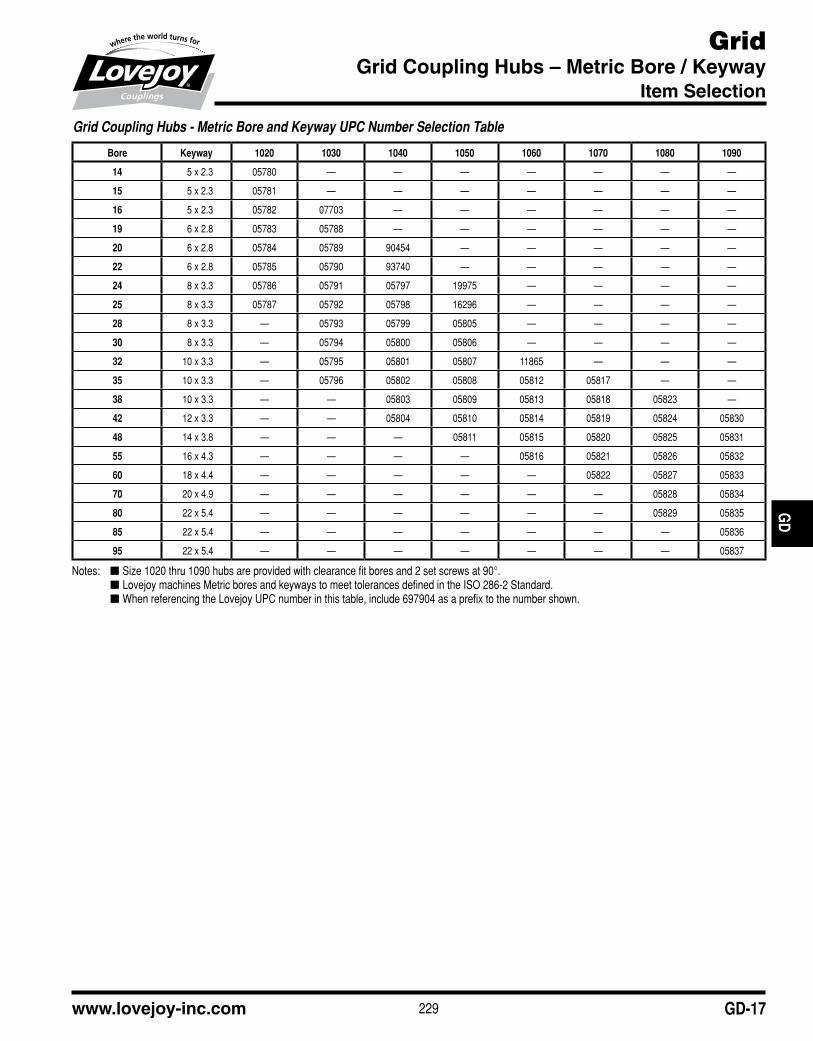
GridGrid Coupling Hubs – Metric Bore / Keyway
Item Selection
Notes:■ n Size■1020■thru■1090■hubs■are■provided■with■clearance■fit■bores■and■2■set■screws■at■90°.■ n Lovejoy■machines■Metric■bores■and■keyways■to■meet■tolerances■defined■in■the■ISO■286-2■Standard.■ n When■referencing■the■Lovejoy■UPC■number■in■this■table,■include■697904■as■a■prefix■to■the■number■shown.
JWJI
SC
JSF
MC
GH
PG
DD
TSP
UJ
VSD
RSL
DED
JWJIS
CJ
SFM
CG
HP
GD
DT
SPU
JVSD
RSLD
ED
Grid Coupling Hubs - Metric Bore and Keyway UPC Number Selection Table
Bore Keyway 1020 1030 1040 1050 1060 1070 1080 1090
14 5■x■2.3 05780 — — — — — — —
15 5■x■2.3 05781 — — — — — — —
16 5■x■2.3 05782 07703 — — — — — —
19 6■x■2.8 05783 05788 — — — — — —
20 6■x■2.8 05784 05789 90454 — — — — —
22 6■x■2.8 05785 05790 93740 — — — — —
24 8■x■3.3 05786 05791 05797 19975 — — — —
25 8■x■3.3 05787 05792 05798 16296 — — — —
28 8■x■3.3 — 05793 05799 05805 — — — —
30 8■x■3.3 — 05794 05800 05806 — — — —
32 10■x■3.3 — 05795 05801 05807 11865 — — —
35 10■x■3.3 — 05796 05802 05808 05812 05817 — —
38 10■x■3.3 — — 05803 05809 05813 05818 05823 —
42 12■x■3.3 — — 05804 05810 05814 05819 05824 05830
48 14■x■3.8 — — — 05811 05815 05820 05825 05831
55 16■x■4.3 — — — — 05816 05821 05826 05832
60 18■x■4.4 — — — — — 05822 05827 05833
70 20■x■4.9 — — — — — — 05828 05834
80 22■x■5.4 — — — — — — 05829 05835
85 22■x■5.4 — — — — — — — 05836
95 22■x■5.4 — — — — — — — 05837
230 630-852-0500
JWJI
SC
JSF
MC
GH
PG
DD
TSP
UJ
VSD
RSL
DED
JWJIS
CJ
SFM
CG
HP
GD
DT
SPU
JVSD
RSLD
ED
GD-18
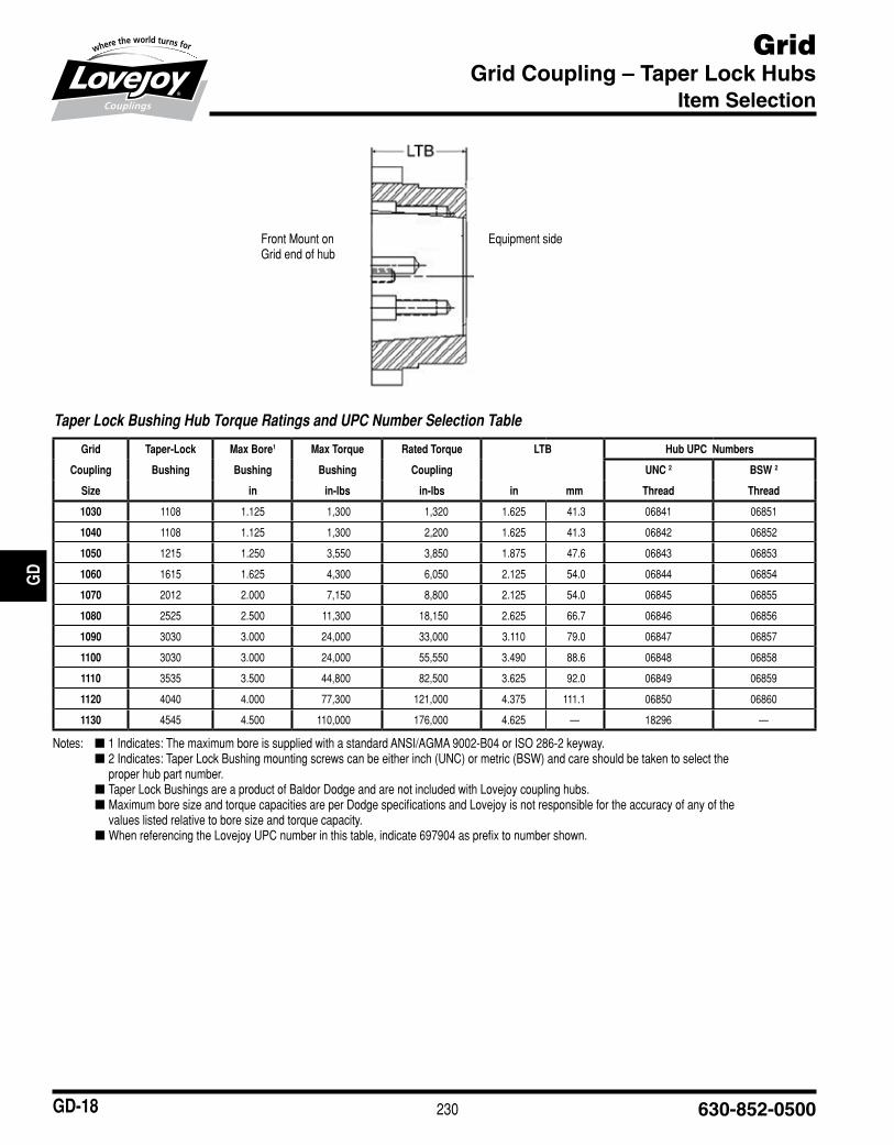
GridGrid Coupling – Taper Lock Hubs
Item Selection
Notes:■ n 1■Indicates:■The■maximum■bore■is■supplied■with■a■standard■ANSI/AGMA■9002-B04■or■ISO■286-2■keyway.■ n 2■Indicates:■Taper■Lock■Bushing■mounting■screws■can■be■either■inch■(UNC)■or■metric■(BSW)■and■care■should■be■taken■to■select■the■
proper■hub■part■number.■ n Taper■Lock■Bushings■are■a■product■of■Baldor■Dodge■and■are■not■included■with■Lovejoy■coupling■hubs. n Maximum■bore■size■and■torque■capacities■are■per■Dodge■specifications■and■Lovejoy■is■not■responsible■for■the■accuracy■of■any■of■the■
values■listed■relative■to■bore■size■and■torque■capacity. n When■referencing■the■Lovejoy■UPC■number■in■this■table,■indicate■697904■as■prefix■to■number■shown.
Front■Mount■on■Grid■end■of■hub
Equipment■side
Taper Lock Bushing Hub Torque Ratings and UPC Number Selection Table
Grid Taper-Lock Max Bore1 Max Torque Rated Torque LTB Hub UPC Numbers
Coupling Bushing Bushing Bushing Coupling UNC 2 BSW 2
Size in in-lbs in-lbs in mm Thread Thread
1030 1108 1.125 1,300 1,320 1.625 41.3 06841 06851
1040 1108 1.125 1,300 2,200 1.625 41.3 06842 06852
1050 1215 1.250 3,550 3,850 1.875 47.6 06843 06853
1060 1615 1.625 4,300 6,050 2.125 54.0 06844 06854
1070 2012 2.000 7,150 8,800 2.125 54.0 06845 06855
1080 2525 2.500 11,300 18,150 2.625 66.7 06846 06856
1090 3030 3.000 24,000 33,000 3.110 79.0 06847 06857
1100 3030 3.000 24,000 55,550 3.490 88.6 06848 06858
1110 3535 3.500 44,800 82,500 3.625 92.0 06849 06859
1120 4040 4.000 77,300 121,000 4.375 111.1 06850 06860
1130 4545 4.500 110,000 176,000 4.625 — 18296 —

231www.lovejoy-inc.com
JWJI
SC
JSF
MC
GH
PG
DD
TSP
UJ
VSD
RSL
DED
JWJIS
CJ
SFM
CG
HP
GD
DT
SPU
JVSD
RSLD
ED
GD-19
GridGrid Coupling – Component Part Numbers
Item Selection
Tapered Component UPC Number Selection Table
Sizes■→ 1020 1030 1040 1050 1060 1070 1080 1090 1100 1110 1120 1130 1140
Grid Only 05244 05245 05246 05247 05248 05249 05250 05251 05252 05253 05254 05255 05256
Horizontal Design:
Cover/Grid Assembly-Metric 05366 05367 05368 05369 05370 05371 05372 05373 05374 05375 05376 05377 05378
Cover/Grid Assembly-Inch 05349 05350 05351 05352 05353 05354 05355 05356 05357 05358 05359 05360 05361
Cover Set-Metric 05290 05291 05292 05293 05294 05295 05296 05297 05298 05299 05300 05301 05302
Cover Set-Inch 05273 05274 05275 05276 05277 05278 05279 05280 05281 05282 05283 05284 05285
Seal Kit 05176 05177 05178 05179 05180 05181 05182 05183 05184 05185 05186 05187 05188
Cover Hardware-Metric 05210 05210 05210 05211 05211 05212 05212 05212 05213 05213 05214 05214 05214
Cover Hardware-Inch 05433 05433 05433 05434 05434 05435 05435 05435 05436 05436 05437 05437 05437
Vertical Design:
Cover/Grid Assembly-Metric 05400 05401 05402 05403 05404 05405 05406 05407 05408 05409 05410 05411 05412
Cover/Grid Assembly-Inch 05383 05384 05385 05386 05387 05388 05389 05390 05391 05392 05393 05394 05395
Cover Set-Metric 05328 05329 05330 05331 05332 05333 05334 05335 05336 05337 05338 05339 05340
Cover Set-Inch 05307 05308 05309 05310 05311 05312 05313 05314 05315 05316 05317 05318 05319
Seal Kit 05189 05190 05191 05192 05193 05194 05195 05196 05197 05198 05199 05200 05201
Cover Hardware-Metric 05215 05216 05216 05217 05217 05217 05218 05218 05219 05219 05220 05221 05222
Cover Hardware-Inch 05442 05443 05443 05444 05444 05444 05445 05445 05446 05446 05447 05448 05449
Notes:■ n The■"Cover/Grid■Assembly"■includes■ALL■components■of■the■coupling■except■the■hubs■and■spacers.■ n The■terms■"Inch"■and■"Metric"■refer■to■the■hardware■(bolts,■etc.).■ n The■"Cover■Set"■contains■the■parts■of■the■Cover/Grid■Assembly■without■the■grid■spring. n The■"Seal■Kit"■contains■the■rubber■seals,■gasket(s),■and■lube■plugs. n "Cover■Hardware"■includes■the■fasteners■that■hold■the■cover■together. n Grease■packets■are■included■with■all■Cover■Sets■and■Cover/Grid■Assemblies■thru■coupling■size■1090. n When■referencing■the■Lovejoy■UPC■number■in■this■table,■include■697904■as■a■prefix■to■the■number■shown.
Notes:■ n The■"Cover/Grid■Assembly"■includes■ALL■components■of■the■coupling■except■the■hubs■and■spacers.■ n The■terms■"Inch"■and■"Metric"■refer■to■the■hardware■(bolts,■etc.)■ n The■"Cover■Set"■contains■the■parts■of■the■Cover/Grid■Assembly■without■the■grid■spring. n The■"Seal■Kit"■contains■the■rubber■seals,■gasket(s),■and■lube■plugs. n "Cover■Hardware"■includes■the■fasteners■that■hold■the■cover■together. n When■referencing■the■Lovejoy■UPC■number■in■this■table,■include■697904■as■a■prefix■to■the■number■shown.
Straight Component UPC Number Selection Table
Sizes■■→ 1150 1160 1170 1180 1190 1200
Horizontal Design:
Hub 73mm RSB 05587 — — — — —
Hub 100mm RSB — 05589 05591 — — —
Hub 125mm RSB — — — 05593 — —
Hub 152mm RSB — — — — 99508 —
Hub 178mm RSB — — — — — 99257
Grid Only 05257 05258 05329 05260 99254 99255
Cover/Grid Assembly-Metric 05379 05380 05381 05382 99270 10953
Cover/Grid Assembly-Inch 05362 05363 05364 05365 10555 10559
Cover Set-Metric 05303 05304 05305 05306 99271 10951
Cover Set-Inch 05286 05287 05288 05289 10556 10560
Seal Kit 05425 05426 05427 05428 10557 10561
Cover Hardware-Metric 05429 05429 05430 05430 — —
Cover Hardware-Inch 05438 05438 05439 05439 10558 10562
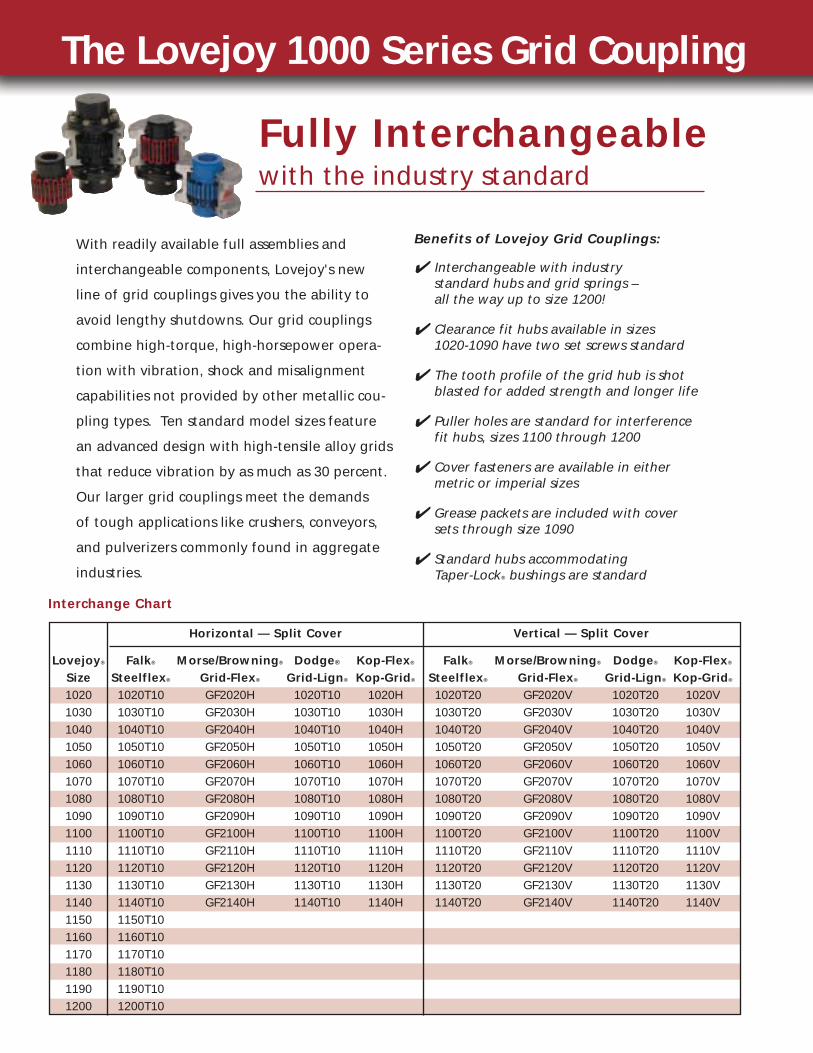
The Lovejoy 1000 Series Grid Coupling
Lovejoy® Falk® Morse/Browning® Dodge® Kop-Flex® Falk® Morse/Browning® Dodge® Kop-Flex®
Size Steelflex® Grid-Flex® Grid-Lign® Kop-Grid® Steelflex® Grid-Flex® Grid-Lign® Kop-Grid®
1020 1020T10 GF2020H 1020T10 1020H 1020T20 GF2020V 1020T20 1020V1030 1030T10 GF2030H 1030T10 1030H 1030T20 GF2030V 1030T20 1030V1040 1040T10 GF2040H 1040T10 1040H 1040T20 GF2040V 1040T20 1040V1050 1050T10 GF2050H 1050T10 1050H 1050T20 GF2050V 1050T20 1050V1060 1060T10 GF2060H 1060T10 1060H 1060T20 GF2060V 1060T20 1060V1070 1070T10 GF2070H 1070T10 1070H 1070T20 GF2070V 1070T20 1070V1080 1080T10 GF2080H 1080T10 1080H 1080T20 GF2080V 1080T20 1080V1090 1090T10 GF2090H 1090T10 1090H 1090T20 GF2090V 1090T20 1090V1100 1100T10 GF2100H 1100T10 1100H 1100T20 GF2100V 1100T20 1100V1110 1110T10 GF2110H 1110T10 1110H 1110T20 GF2110V 1110T20 1110V1120 1120T10 GF2120H 1120T10 1120H 1120T20 GF2120V 1120T20 1120V1130 1130T10 GF2130H 1130T10 1130H 1130T20 GF2130V 1130T20 1130V1140 1140T10 GF2140H 1140T10 1140H 1140T20 GF2140V 1140T20 1140V1150 1150T101160 1160T101170 1170T101180 1180T101190 1190T101200 1200T10
Horizontal — Split Cover
Interchange Chart
Vertical — Split Cover
With readily available full assemblies and
interchangeable components, Lovejoy's new
line of grid couplings gives you the ability to
avoid lengthy shutdowns. Our grid couplings
combine high-torque, high-horsepower opera-
tion with vibration, shock and misalignment
capabilities not provided by other metallic cou-
pling types. Ten standard model sizes feature
an advanced design with high-tensile alloy grids
that reduce vibration by as much as 30 percent.
Our larger grid couplings meet the demands
of tough applications like crushers, conveyors,
and pulverizers commonly found in aggregate
industries.
Benefits of Lovejoy Grid Couplings:
✔ Interchangeable with industry standard hubs and grid springs – all the way up to size 1200!
✔ Clearance fit hubs available in sizes 1020-1090 have two set screws standard
✔ The tooth profile of the grid hub is shot blasted for added strength and longer life
✔ Puller holes are standard for interference fit hubs, sizes 1100 through 1200
✔ Cover fasteners are available in either metric or imperial sizes
✔ Grease packets are included with cover sets through size 1090
✔ Standard hubs accommodating Taper-Lock® bushings are standard
Fully Interchangeablewith the industry standard
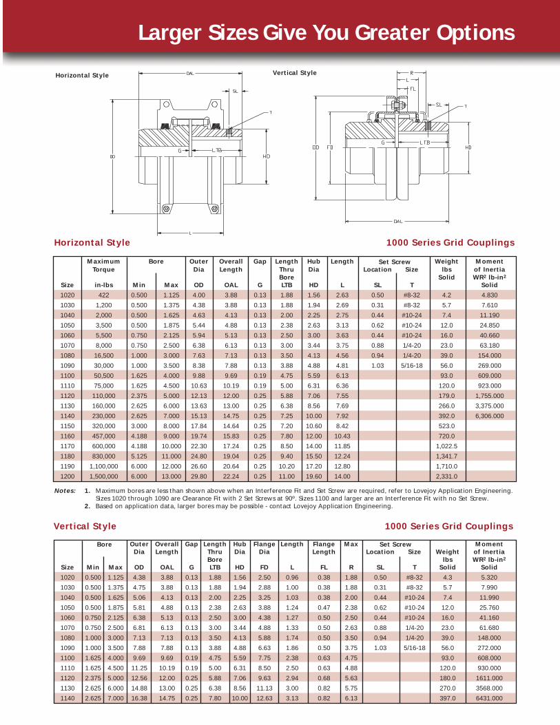
Maximum Outer Overall Gap Length Hub Length Weight MomentTorque Dia Length Thru Dia Location Size lbs of Inertia
Bore Solid WR2 lb-in2
Size in-lbs Min Max OD OAL G LTB HD L SL T Solid
1020 422 0.500 1.125 4.00 3.88 0.13 1.88 1.56 2.63 0.50 #8-32 4.2 4.830
1030 1,200 0.500 1.375 4.38 3.88 0.13 1.88 1.94 2.69 0.31 #8-32 5.7 7.610
1040 2,000 0.500 1.625 4.63 4.13 0.13 2.00 2.25 2.75 0.44 #10-24 7.4 11.190
1050 3,500 0.500 1.875 5.44 4.88 0.13 2.38 2.63 3.13 0.62 #10-24 12.0 24.850
1060 5,500 0.750 2.125 5.94 5.13 0.13 2.50 3.00 3.63 0.44 #10-24 16.0 40.660
1070 8,000 0.750 2.500 6.38 6.13 0.13 3.00 3.44 3.75 0.88 1/4-20 23.0 63.180
1080 16,500 1.000 3.000 7.63 7.13 0.13 3.50 4.13 4.56 0.94 1/4-20 39.0 154.000
1090 30,000 1.000 3.500 8.38 7.88 0.13 3.88 4.88 4.81 1.03 5/16-18 56.0 269.000
1100 50,500 1.625 4.000 9.88 9.69 0.19 4.75 5.59 6.13 93.0 609.000
1110 75,000 1.625 4.500 10.63 10.19 0.19 5.00 6.31 6.36 120.0 923.000
1120 110,000 2.375 5.000 12.13 12.00 0.25 5.88 7.06 7.55 179.0 1,755.000
1130 160,000 2.625 6.000 13.63 13.00 0.25 6.38 8.56 7.69 266.0 3,375.000
1140 230,000 2.625 7.000 15.13 14.75 0.25 7.25 10.00 7.92 392.0 6,306.000
1150 320,000 3.000 8.000 17.84 14.64 0.25 7.20 10.60 8.42 523.0
1160 457,000 4.188 9.000 19.74 15.83 0.25 7.80 12.00 10.43 720.0
1170 600,000 4.188 10.000 22.30 17.24 0.25 8.50 14.00 11.85 1,022.5
1180 830,000 5.125 11.000 24.80 19.04 0.25 9.40 15.50 12.24 1,341.7
1190 1,100,000 6.000 12.000 26.60 20.64 0.25 10.20 17.20 12.80 1,710.0
1200 1,500,000 6.000 13.000 29.80 22.24 0.25 11.00 19.60 14.00 2,331.0
Horizontal Style 1000 Series Grid Couplings
Larger Sizes Give You Greater Options
Outer Overall Gap Length Hub Flange Length Flange Max MomentDia Length Thru Dia Dia Length Location Size Weight of Inertia
Bore lbs WR2 lb-in2
Size Min Max OD OAL G LTB HD FD L FL R SL T Solid Solid
1020 0.500 1.125 4.38 3.88 0.13 1.88 1.56 2.50 0.96 0.38 1.88 0.50 #8-32 4.3 5.320
1030 0.500 1.375 4.75 3.88 0.13 1.88 1.94 2.88 1.00 0.38 1.88 0.31 #8-32 5.7 7.990
1040 0.500 1.625 5.06 4.13 0.13 2.00 2.25 3.25 1.03 0.38 2.00 0.44 #10-24 7.4 11.990
1050 0.500 1.875 5.81 4.88 0.13 2.38 2.63 3.88 1.24 0.47 2.38 0.62 #10-24 12.0 25.760
1060 0.750 2.125 6.38 5.13 0.13 2.50 3.00 4.38 1.27 0.50 2.50 0.44 #10-24 16.0 41.160
1070 0.750 2.500 6.81 6.13 0.13 3.00 3.44 4.88 1.33 0.50 2.63 0.88 1/4-20 23.0 61.680
1080 1.000 3.000 7.13 7.13 0.13 3.50 4.13 5.88 1.74 0.50 3.50 0.94 1/4-20 39.0 148.000
1090 1.000 3.500 7.88 7.88 0.13 3.88 4.88 6.63 1.86 0.50 3.75 1.03 5/16-18 56.0 272.000
1100 1.625 4.000 9.69 9.69 0.19 4.75 5.59 7.75 2.38 0.63 4.75 93.0 608.000
1110 1.625 4.500 11.25 10.19 0.19 5.00 6.31 8.50 2.50 0.63 4.88 120.0 930.000
1120 2.375 5.000 12.56 12.00 0.25 5.88 7.06 9.63 2.94 0.68 5.63 180.0 1611.000
1130 2.625 6.000 14.88 13.00 0.25 6.38 8.56 11.13 3.00 0.82 5.75 270.0 3568.000
1140 2.625 7.000 16.38 14.75 0.25 7.80 10.00 12.63 3.13 0.82 6.13 397.0 6431.000
Vertical Style 1000 Series Grid Couplings
Bore Set Screw
Horizontal Style
Notes: 1. Maximum bores are less than shown above when an Interference Fit and Set Screw are required, refer to Lovejoy Application Engineering.Sizes 1020 through 1090 are Clearance Fit with 2 Set Screws at 90º. Sizes 1100 and larger are an Interference Fit with no Set Screw.
2. Based on application data, larger bores may be possible - contact Lovejoy Application Engineering.
Bore Set Screw
Vertical Style
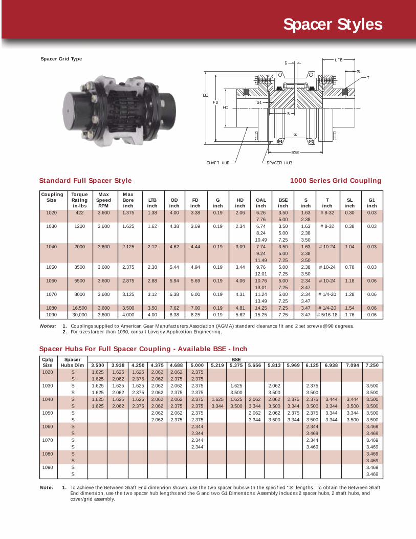
Spacer Grid Type
Spacer Styles
Coupling Torque Max Max Size Rating Speed Bore LTB OD FD G HD OAL BSE S T SL G1
in-lbs RPM inch inch inch inch inch inch inch inch inch inch inch inch1020 422 3,600 1.375 1.38 4.00 3.38 0.19 2.06 6.26 3.50 1.63 # 8-32 0.30 0.03
7.76 5.00 2.381030 1200 3,600 1.625 1.62 4.38 3.69 0.19 2.34 6.74 3.50 1.63 # 8-32 0.38 0.03
8.24 5.00 2.3810.49 7.25 3.50
1040 2000 3,600 2.125 2.12 4.62 4.44 0.19 3.09 7.74 3.50 1.63 # 10-24 1.04 0.039.24 5.00 2.38
11.49 7.25 3.501050 3500 3,600 2.375 2.38 5.44 4.94 0.19 3.44 9.76 5.00 2.38 # 10-24 0.78 0.03
12.01 7.25 3.501060 5500 3,600 2.875 2.88 5.94 5.69 0.19 4.06 10.76 5.00 2.34 # 10-24 1.18 0.06
13.01 7.25 3.471070 8000 3,600 3.125 3.12 6.38 6.00 0.19 4.31 11.24 5.00 2.34 # 1/4-20 1.28 0.06
13.49 7.25 3.471080 16,500 3,600 3.500 3.50 7.62 7.00 0.19 4.81 14.25 7.25 3.47 # 1/4-20 1.54 0.061090 30,000 3,600 4.000 4.00 8.38 8.25 0.19 5.62 15.25 7.25 3.47 # 5/16-18 1.76 0.06
Cplg SpacerSize Hubs Dim 3.500 3.938 4.250 4.375 4.688 5.000 5.219 5.375 5.656 5.813 5.969 6.125 6.938 7.094 7.2501020 S 1.625 1.625 1.625 2.062 2.062 2.375
S 1.625 2.062 2.375 2.062 2.375 2.3751030 S 1.625 1.625 1.625 2.062 2.062 2.375 1.625 2.062 2.375 3.500
S 1.625 2.062 2.375 2.062 2.375 2.375 3.500 3.500 3.500 3.5001040 S 1.625 1.625 1.625 2.062 2.062 2.375 1.625 1.625 2.062 2.062 2.375 2.375 3.444 3.444 3.500
S 1.625 2.062 2.375 2.062 2.375 2.375 3.344 3.500 3.344 3.500 3.344 3.500 3.344 3.500 3.5001050 S 2.062 2.062 2.375 2.062 2.062 2.375 2.375 3.344 3.344 3.500
S 2.062 2.375 2.375 3.344 3.500 3.344 3.500 3.344 3.500 3.5001060 S 2.344 2.344 3.469
S 2.344 3.469 3.4691070 S 2.344 2.344 3.469
S 2.344 3.469 3.4691080 S 3.469
S 3.4691090 S 3.469
S 3.469
BSE
Standard Full Spacer Style 1000 Series Grid Coupling
Spacer Hubs For Full Spacer Coupling - Available BSE - Inch
Note: 1. To achieve the Between Shaft End dimension shown, use the two spacer hubs with the specified “S” lengths. To obtain the Between ShaftEnd dimension, use the two spacer hub lengths and the G and two G1 Dimensions. Assembly includes 2 spacer hubs, 2 shaft hubs, andcover/grid assembly.
Notes: 1. Couplings supplied to American Gear Manufacturers Association (AGMA) standard clearance fit and 2 set screws @ 90 degrees.2. For sizes larger than 1090, consult Lovejoy Application Engineering.

Horizontal VerticalSize 100 1200 1800 3600 in-lbs Nm inch mm Max RPM Max RPM
1020 0.67 8.04 12.06 24.12 422 48 1.125 27 4500 6000
1030 1.88 22.56 33.84 67.68 1,200 136 1.375 35 4500 6000
1040 3.22 38.64 57.96 115.92 2,000 226 1.625 44 4500 6000
1050 5.49 65.88 98.82 197.64 3,500 395 1.875 51 4500 6000
1060 8.71 104.52 156.78 313.56 5,500 621 2.125 57 4350 6000
1070 12.73 152.76 229.14 458.28 8,000 904 2.500 68 4125 5500
1080 26.13 313.56 470.34 940.68 16,500 1,864 3.000 83 3600 4750
1090 47.57 570.84 856.26 1712.52 30,000 3,390 3.500 95 3600 4000
1100 80.00 960.00 1440.00 50,500 5,706 4.000 108 2440 3250
1110 119.00 1428.00 2142.00 75,000 8,474 4.500 117 2250 3000
1120 175.50 2106.00 3159.00 110,000 12,428 5.000 137 2025 2700
1130 253.30 3039.60 4559.40 160,000 18,078 6.000 165 1800 2400
1140 364.50 4374.00 6561.00 230,000 25,987 7.000 184 1650 2200
1150 509.58 6114.96 320,000 36,300 8.000 200 1500
1160 724.14 8689.68 457,000 51,600 9.000 228 1350
1170 952.11 11425.32 600,000 67,800 10.000 254 1225
1180 1314.18 830,000 93,600 11.000 280 1100
1190 1750.00 1,100,000 124,278 12.000 305 1050
1200 2385.00 1,500,000 169,470 13.000 330 900
Basic HP Ratings @ Varying RPM
Torque and Horsepower Ratings
Maximum BoreTorque Ratings
Coupling Parallel Angular Parallel Angular 10%Size P X-Y P X-Y G
1020 0.006 0.002 0.012 0.010 0.118
1030 0.006 0.003 0.012 0.011 0.118
1040 0.006 0.003 0.012 0.013 0.118
1050 0.008 0.004 0.016 0.015 0.118
1060 0.008 0.004 0.016 0.018 0.118
1070 0.008 0.005 0.016 0.020 0.118
1080 0.008 0.006 0.016 0.024 0.118
1090 0.008 0.007 0.016 0.028 0.118
1100 0.010 0.008 0.020 0.032 0.177
1110 0.010 0.009 0.020 0.035 0.177
1120 0.011 0.010 0.022 0.040 0.236
1130 0.011 0.012 0.022 0.047 0.236
1140 0.011 0.013 0.022 0.053 0.236
1150 0.012 0.015 0.024 0.061 0.236
1160 0.012 0.017 0.024 0.070 0.236
1170 0.012 0.020 0.024 0.079 0.236
1180 0.015 0.022 0.030 0.089 0.236
1190 0.015 0.024 0.030 0.096 0.236
1200 0.015 0.027 0.030 0.107 0.236
Max InstallationMisalignment
Max InstallationMisalignment
NormalGap
Misalignment Capacity
Note: 1. Misalignment ratings pertain to both standard and spacer grid couplings.
The movement of the grid in the hub groovesaccommodates parallel misalignment and stillpermits full functioning of the grid-grooveaction in damping out shock and vibration.
Under angular misalignment, the grid-groovedesign permits a rocking and sliding action ofthe grid and hubs without any loss of powerthrough the resilient grid.
End float is permitted for both driving anddriven members because the grid slides freelyin the grooves.
Parallel
Angular
Axial
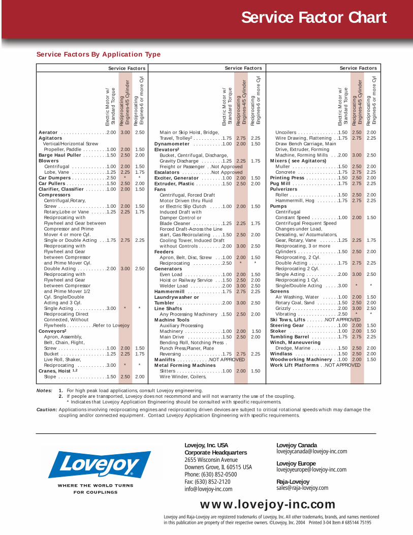
Service Factors
Elec
tric
Mo
tor
w/
Stan
dar
d T
orq
ue
Rec
ipro
cati
ng
En
gin
es-4
/5 C
ylin
der
Rec
ipro
cati
ng
En
gin
es-6
or
mo
re C
yl
Service Factors
Elec
tric
Mo
tor
w/
Stan
dar
d T
orq
ue
Rec
ipro
cati
ng
En
gin
es-4
/5 C
ylin
der
Rec
ipro
cati
ng
En
gin
es-6
or
mo
re C
yl
Applications That Benefit From Grid Couplings
Aerator . . . . . . . . . . . . . . . . .2.00 3.00 2.50Agitators
Vertical/Horizontal Screw Propeller, Paddle . . . . . . . . .1.00 2.00 1.50
Barge Haul Puller . . . . . . . . .1.50 2.50 2.00Blowers
Centrifugal . . . . . . . . . . . . .1.00 2.00 1.50Lobe, Vane . . . . . . . . . . . . .1.25 2.25 1.75
Car Dumpers . . . . . . . . . . . . .2.50 * *Car Pullers . . . . . . . . . . . . . . .1.50 2.50 2.00Clarifier, Classifier . . . . . . . .1.00 2.00 1.50Compressors
Centrifugal,Rotary, Screw . . . . . . . . . . . . . . . . . .1.00 2.00 1.50Rotary,Lobe or Vane . . . . . .1.25 2.25 1.75Reciprocating with Flywheel and Gear between Compressor and Prime Mover 4 or more Cyl. Single or Double Acting . . .1.75 2.75 2.25Reciprocating with Flywheel and Gear between Compressorand Prime Mover Cyl. Double Acting . . . . . . . . . . .2.00 3.00 2.50Reciprocating with Flywheel and Gear between Compressor and Prime Mover 1/2 Cyl. Single/Double Acting and 3 Cyl.Single Acting . . . . . . . . . . . .3.00 * *Reciprocating Direct Connected, WithoutFlywheels . . . . . . . . . .Refer to Lovejoy
Conveyors2
Apron, Assembly, Belt, Chain, Flight, Screw . . . . . . . . . . . . . . . . . .1.00 2.00 1.50Bucket . . . . . . . . . . . . . . . . .1.25 2.25 1.75Live Roll, Shaker,Reciprocating . . . . . . . . . . .3.00 * *
Cranes, Hoist 1,2
Slope . . . . . . . . . . . . . . . . . .1.50 2.50 2.00
Main or Skip Hoist, Bridge,Travel, Trolley2 . . . . . . . . . . .1.75 2.75 2.25
Dynamometer . . . . . . . . . . .1.00 2.00 1.50Elevators2
Bucket, Centrifugal, Discharge,Gravity Discharge . . . . . . . .1.25 2.25 1.75Freight or Passenger . .Not Approved
Escalators . . . . . . . . . . .Not ApprovedExciter, Generator . . . . . . . .1.00 2.00 1.50Extruder, Plastic . . . . . . . . . .1.50 2.50 2.00Fans
Centrifugal, Forced Draft Motor Driven thru Fluid or Electric Slip Clutch . . . . .1.00 2.00 1.50Induced Draft with Damper Control or Blade Cleaner . . . . . . . . . . .1.25 2.25 1.75Forced Draft-Across the Linestart, Gas Recirculating . . . .1.50 2.50 2.00Cooling Tower, Induced Draftwithout Controls . . . . . . . . .2.00 3.00 2.50
FeedersApron, Belt, Disc, Screw . . .1.00 2.00 1.50Reciprocating . . . . . . . . . . .2.50 * *
GeneratorsEven Load . . . . . . . . . . . . . .1.00 2.00 1.50Hoist or Railway Service . . .1.50 2.50 2.00Welder Load . . . . . . . . . . . .2.00 3.00 2.50
Hammermill . . . . . . . . . . . . .1.75 2.75 2.25Laundrywasher or Tumbler . . . . . . . . . . . . . . . . .2.00 3.00 2.50Line Shafts
Any Processing Machinery .1.50 2.50 2.00Machine Tools
Auxiliary Processing Machinery . . . . . . . . . . . . . .1.00 2.00 1.50Main Drive . . . . . . . . . . . . .1.50 2.50 2.00Bending Roll, Notching Press .Punch Press,Planer, PlateReversing . . . . . . . . . . . . . . .1.75 2.75 2.25
Manlifts . . . . . . . . . . . .NOT APPROVEDMetal Forming Machines
Slitters . . . . . . . . . . . . . . . . .1.00 2.00 1.50Wire Winder, Coilers,
Uncoilers . . . . . . . . . . . . . . .1.50 2.50 2.00Wire Drawing, Flattening . .1.75 2.75 2.25Draw Bench Carriage, MainDrive, Extruder, FormingMachine, Forming Mills . . .2.00 3.00 2.50
Mixers ( see Agitators)Muller . . . . . . . . . . . . . . . . .1.50 2.50 2.00Concrete . . . . . . . . . . . . . . .1.75 2.75 2.25
Printing Press . . . . . . . . . . . .1.50 2.50 2.00Pug Mill . . . . . . . . . . . . . . . . .1.75 2.75 2.25Pulverizers
Roller . . . . . . . . . . . . . . . . . .1.50 2.50 2.00Hammermill, Hog . . . . . . . .1.75 2.75 2.25
PumpsCentrifugal Constant Speed . . . . . . . . . .1.00 2.00 1.50Centrifugal Frequent SpeedChanges under Load, Descaling, w/ Accumulators, Gear, Rotary, Vane . . . . . . .1.25 2.25 1.75Reciprocating, 3 or moreCylinders . . . . . . . . . . . . . . .1.50 2.50 2.00Reciprocating, 2 Cyl. Double Acting . . . . . . . . . . .1.75 2.75 2.25Reciprocating 2 Cyl. Single Acting . . . . . . . . . . . .2.00 3.00 2.50Reciprocating 1 Cyl. Single/Double Acting . . . . .3.00 * *
ScreensAir Washing, Water . . . . . .1.00 2.00 1.50Rotary Coal, Sand . . . . . . . .1.50 2.50 2.00Grizzly . . . . . . . . . . . . . . . . .2.00 3.00 2.50Vibrating . . . . . . . . . . . . . . .2.50 * *
Ski Tows, Lifts . . . . . . .NOT APPROVEDSteering Gear . . . . . . . . . . . .1.00 2.00 1.50Stoker . . . . . . . . . . . . . . . . . .1.00 2.00 1.50Tumbling Barrel . . . . . . . . . .1.75 2.75 2.25Winch, Maneuvering
Dredge, Marine . . . . . . . . . .1.50 2.50 2.00Windlass . . . . . . . . . . . . . . . .1.50 2.50 2.00Woodworking Machinery . .1.00 2.00 1.50Work Lift Platforms . .NOT APPROVED
Notes: 1. For high peak load applications, consult Lovejoy engineering.2. If people are transported, Lovejoy does not recommond and will not warranty the use of the coupling.
* Indicates that Lovejoy Application Engineering should be consulted with specific requirements.
Caution: Applications involving reciprocating engines and reciprocating driven devices are subject to critical rotational speeds which may damage thecoupling and/or connected equipment. Contact Lovejoy Application Engineering with specific requirements.
Service Factor Chart
Service Factors By Application Type
Service Factors
Elec
tric
Mo
tor
w/
Stan
dar
d T
orq
ue
Rec
ipro
cati
ng
En
gin
es-4
/5 C
ylin
der
Rec
ipro
cati
ng
En
gin
es-6
or
mo
re C
yl
where the world turnsfor couplings
Lovejoy, Inc. USACorporate Headquarters2655 Wisconsin AvenueDowners Grove, IL 60515 USAPhone: (630) 852-0500Fax: (630) [email protected]
Lovejoy [email protected]
Lovejoy [email protected]
www.lovejoy-inc.comLovejoy and Raja-Lovejoy are registered trademarks of Lovejoy, Inc. All other trademarks, brands, and names mentionedin this publication are property of their respective owners. ©Lovejoy, Inc. 2004 Printed 3-04 Item # 685144 75195