Embed Size (px)
Citation preview
23-mm Glass EncapsulatedTransponder
Reference Guide
July 1996
SCBU018
23-mm Glass Encapsulated Transponder
Reference Guide
Literature Number: SCBU018
July 1996
Contents
1 Introduction................................................................................................................ 62 Transponder Packaging ............................................................................................... 63 Product Codes............................................................................................................ 74 Function .................................................................................................................... 7
4.1 Read (Reading of RO and R/W Transponders).............................................................. 7
4.2 Write and Program............................................................................................... 9
5 Characteristics of the Pulsed FM System ..................................................................... 115.1 Basic System Data ............................................................................................. 11
5.2 Reader and System Design Impact .......................................................................... 11
5.3 System Performance and Functional Reliability Impact ................................................... 11
5.4 Other Quality Factors of the TIRIS Pulsed FM System ................................................... 12
6 EMI/EMC Performance ............................................................................................... 126.1 General .......................................................................................................... 12
6.2 The Automotive Environment and Factors .................................................................. 12
6.3 TIRIS Pulsed FM Transponder and System Performance ................................................ 12
7 Measurement Set-Ups ................................................................................................ 147.1 Measurement Set-Up: Resonance Frequency, Bandwidth, Quality Factor of Transponder .......... 14
7.2 Measurement Set-Up: Powering Field Strength ............................................................ 16
7.3 Measurement Set-Up: Transponder Signal Strength ...................................................... 17
8 Absolute Maximum Ratings ........................................................................................ 189 Recommended Operating Conditions .......................................................................... 1810 Characteristics.......................................................................................................... 1811 Environmental Data and Reliability .............................................................................. 1912 Memory .................................................................................................................... 1913 Package ................................................................................................................... 1914 Packing Symbolization............................................................................................... 20Appendix A Conversion Formula ........................................................................................ 21
SCBU018–July 1996 Table of Contents 3Submit Documentation Feedback

List of Figures
1 System Configuration Showing the Reader, Antenna, and Transponder ............................................ 62 Block Diagram of the TIRIS Pulsed FM Transponder .................................................................. 63 Dimensions of the TIRIS 23-mm Transponder (in mm)................................................................. 74 Charge and Read Function of the Transponder, Showing the Voltage at the Transponder and Exciter
(Reader) Coil ................................................................................................................. 85 FM Principle Used for the Read Function of TIRIS Transponders .................................................... 86 Read Data Format of TIRIS RO Transponder ........................................................................... 97 Read Data Format of TIRIS R/W Transponder .......................................................................... 98 Charge, Write, and Program Principle Used for TIRIS, Showing the Voltage at the Exciter (Reader) and
Transponder Antenna Coil ................................................................................................ 109 The Write and Program Function ........................................................................................ 1010 Write Data Format for Programming Function ......................................................................... 1111 EMI Performance Test of the TIRIS System............................................................................ 1312 EMI Performance at Commonly Used Radio Communication Frequencies in Automotive Environment....... 1313 Reading Range Under Broadband Noise (White Noise) Conditions ................................................ 1414 Measurement Set-up For the Determination of Transponder Resonance Frequency, Bandwidth, and
Quality Factor ............................................................................................................... 1515 Determination of the Resonance Frequency and –3-dB Bandwidth by Monitoring the Pick-up Coil Voltage.. 1516 Test Set-up For Powering Field Strength Determination.............................................................. 1617 Received Signal at the Pickup Coil, If Power Field Strength Is Sufficient .......................................... 1718 Determination of the Transponder Signal Strength (Data Transmission Signal Strength) With Helmholtz
Aperture ..................................................................................................................... 1719 Monitored Signal Voltage at the Spectrum Analyzer (Time Domain Mode) ........................................ 18
4 List of Figures SCBU018–July 1996Submit Documentation Feedback
Reference GuideSCBU018–July 1996
xxx
Edition Notice: Fourth Edition – July 1996
This is the fourth edition of this manual, it describes the following transponders:RI-TRP-RRHPRI-TRP-WRHP
This Reference Manual is for customers who wish to use the TIRIS 23-mm Glass EncapsulatedTransponder in Radio Frequency Identification (RFID) installations. The manual includes technicalinformation concerning the function, technical specifications, application and environmental related data.
Texas Instruments reserves the right to change its products or services at any time without notice. TIprovides customer assistance in various technical areas, but does not have full access to data concerningthe uses and applications of customer's products. Therefore TI assumes no responsibility for customerproduct design or for infringement of patents and/or the rights of third parties, which may result fromassistance provided by TI.
The TIRIS™ logo and the word TIRIS™ are registered trademarks of Texas Instruments Incorporated.
Copyright © 1996 Texas Instruments Incorporated.
All rights reserved.
SCBU018–July 1996 xxx 5Submit Documentation Feedback
1 Introduction
CF45538
RF MODULE
FIELD LINES
CONTROL
UNIT
TIRIS READ/WRITE UNIT
ANTENNA AXIS
TRANSMIT/RECEIVE ANTENNA
TRANSPONDER
CHARGE
CAPACITOR
ANTENNA
TRANSPONDER
IC
2 Transponder Packaging
Reference GuideSCBU018–July 1996
xxx
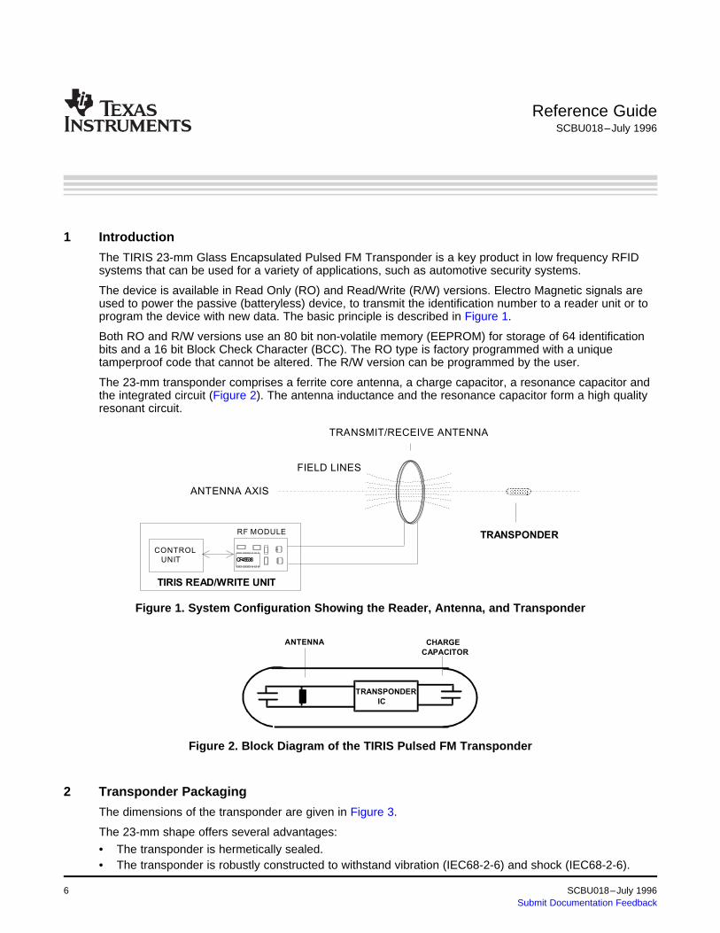
The TIRIS 23-mm Glass Encapsulated Pulsed FM Transponder is a key product in low frequency RFIDsystems that can be used for a variety of applications, such as automotive security systems.
The device is available in Read Only (RO) and Read/Write (R/W) versions. Electro Magnetic signals areused to power the passive (batteryless) device, to transmit the identification number to a reader unit or toprogram the device with new data. The basic principle is described in Figure 1.
Both RO and R/W versions use an 80 bit non-volatile memory (EEPROM) for storage of 64 identificationbits and a 16 bit Block Check Character (BCC). The RO type is factory programmed with a uniquetamperproof code that cannot be altered. The R/W version can be programmed by the user.
The 23-mm transponder comprises a ferrite core antenna, a charge capacitor, a resonance capacitor andthe integrated circuit (Figure 2). The antenna inductance and the resonance capacitor form a high qualityresonant circuit.
Figure 1. System Configuration Showing the Reader, Antenna, and Transponder
Figure 2. Block Diagram of the TIRIS Pulsed FM Transponder
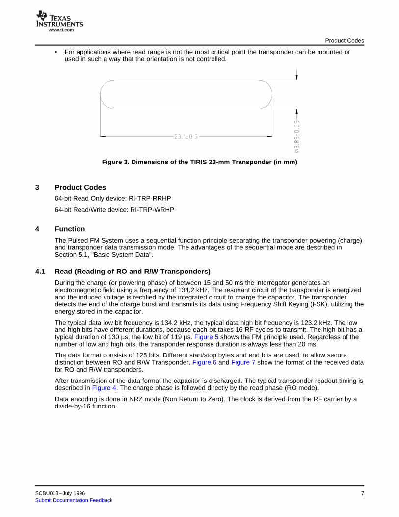
The dimensions of the transponder are given in Figure 3.
The 23-mm shape offers several advantages:
• The transponder is hermetically sealed.• The transponder is robustly constructed to withstand vibration (IEC68-2-6) and shock (IEC68-2-6).
6 xxx SCBU018–July 1996Submit Documentation Feedback
www.ti.com
3 Product Codes
4 Function
4.1 Read (Reading of RO and R/W Transponders)
Product Codes
• For applications where read range is not the most critical point the transponder can be mounted orused in such a way that the orientation is not controlled.
Figure 3. Dimensions of the TIRIS 23-mm Transponder (in mm)
64-bit Read Only device: RI-TRP-RRHP
64-bit Read/Write device: RI-TRP-WRHP
The Pulsed FM System uses a sequential function principle separating the transponder powering (charge)and transponder data transmission mode. The advantages of the sequential mode are described inSection 5.1, "Basic System Data".
During the charge (or powering phase) of between 15 and 50 ms the interrogator generates anelectromagnetic field using a frequency of 134.2 kHz. The resonant circuit of the transponder is energizedand the induced voltage is rectified by the integrated circuit to charge the capacitor. The transponderdetects the end of the charge burst and transmits its data using Frequency Shift Keying (FSK), utilizing theenergy stored in the capacitor.
The typical data low bit frequency is 134.2 kHz, the typical data high bit frequency is 123.2 kHz. The lowand high bits have different durations, because each bit takes 16 RF cycles to transmit. The high bit has atypical duration of 130 µs, the low bit of 119 µs. Figure 5 shows the FM principle used. Regardless of thenumber of low and high bits, the transponder response duration is always less than 20 ms.
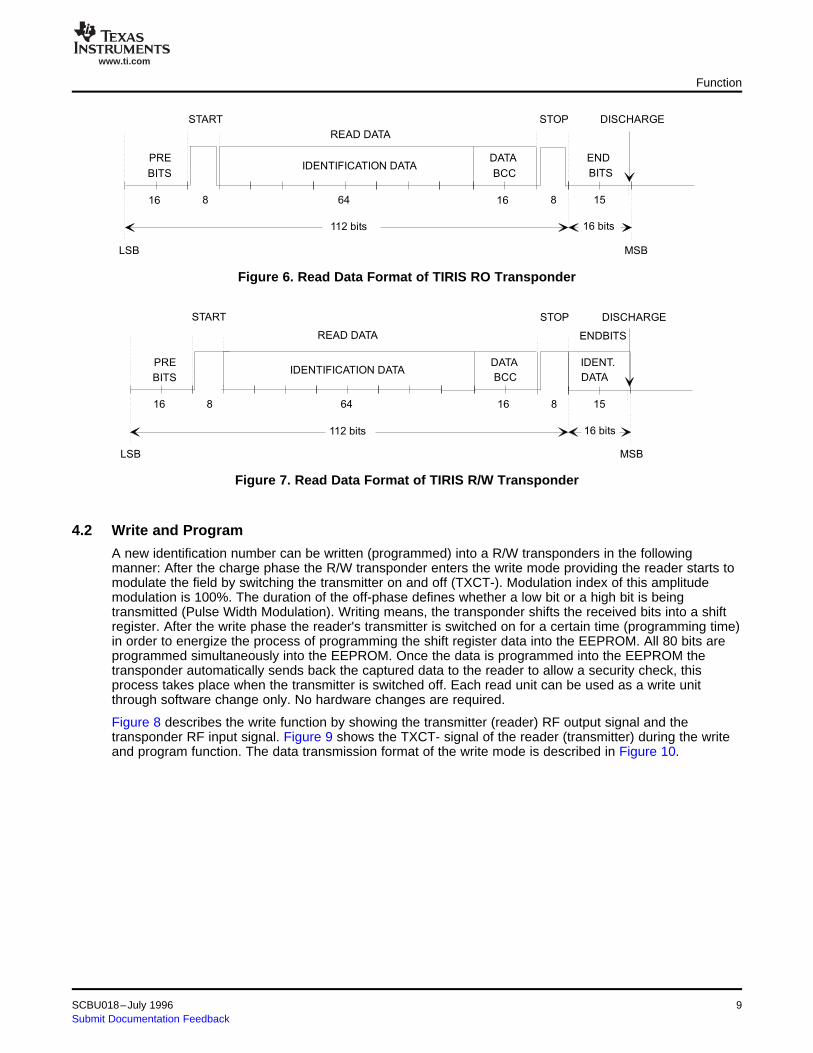
The data format consists of 128 bits. Different start/stop bytes and end bits are used, to allow securedistinction between RO and R/W Transponder. Figure 6 and Figure 7 show the format of the received datafor RO and R/W transponders.
After transmission of the data format the capacitor is discharged. The typical transponder readout timing isdescribed in Figure 4. The charge phase is followed directly by the read phase (RO mode).
Data encoding is done in NRZ mode (Non Return to Zero). The clock is derived from the RF carrier by adivide-by-16 function.
SCBU018–July 1996 xxx 7Submit Documentation Feedback

www.ti.com
VO
LTA
GE
SA
TT
RA
NS
PO
ND
ER
AN
TE
NN
AE
XC
ITE
R V
OLTA
GE
CHARGE PHASE(15...50 MS)
TIME
TIME
READPHASE
CHARGE PHASE(15...50 MS)
At minimum reading range
At maximum reading range
134.2 kHz 123.2 kHz 134.2 kHz 123.2 kHz
0 0 11
129.2 µs 119.9 µs
Function
Figure 4. Charge and Read Function of the Transponder, Showing the Voltage at the Transponder andExciter (Reader) Coil
Figure 5. FM Principle Used for the Read Function of TIRIS Transponders
8 xxx SCBU018–July 1996Submit Documentation Feedback
www.ti.com
16 8 64
112 bits 16 bits
816 15
BITS
READ DATA
IDENTIFICATION DATADATA
BCC
END
BITS
DISCHARGE
MSBLSB
PRE
STOPSTART
16 8 64
112 bits 16 bits
816 15
BITS
READ DATA
IDENTIFICATION DATADATA
BCC
MSBLSB
PRE
STOPSTART
IDENT.
DATA
DISCHARGE
ENDBITS
4.2 Write and Program
Function
Figure 6. Read Data Format of TIRIS RO Transponder
Figure 7. Read Data Format of TIRIS R/W Transponder
A new identification number can be written (programmed) into a R/W transponders in the followingmanner: After the charge phase the R/W transponder enters the write mode providing the reader starts tomodulate the field by switching the transmitter on and off (TXCT-). Modulation index of this amplitudemodulation is 100%. The duration of the off-phase defines whether a low bit or a high bit is beingtransmitted (Pulse Width Modulation). Writing means, the transponder shifts the received bits into a shiftregister. After the write phase the reader's transmitter is switched on for a certain time (programming time)in order to energize the process of programming the shift register data into the EEPROM. All 80 bits areprogrammed simultaneously into the EEPROM. Once the data is programmed into the EEPROM thetransponder automatically sends back the captured data to the reader to allow a security check, thisprocess takes place when the transmitter is switched off. Each read unit can be used as a write unitthrough software change only. No hardware changes are required.
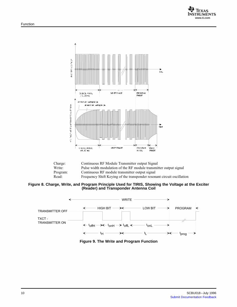
Figure 8 describes the write function by showing the transmitter (reader) RF output signal and thetransponder RF input signal. Figure 9 shows the TXCT- signal of the reader (transmitter) during the writeand program function. The data transmission format of the write mode is described in Figure 10.
SCBU018–July 1996 xxx 9Submit Documentation Feedback
www.ti.com
Charge: Continuous RF Module Transmitter output Signal
Write: Pulse width modulation of the RF module transmitter output signal
Program: Continuous RF module transmitter output signal
Read: Frequency Shift Keying of the transponder resonant circuit oscillation
TRANSMITTER OFF
TXCT -
HIGH BIT PROGRAM
WRITE
LOW BIT
TRANSMITTER ONtoffH tonH toffL tonL
tprogtH tL
Function
Figure 8. Charge, Write, and Program Principle Used for TIRIS, Showing the Voltage at the Exciter(Reader) and Transponder Antenna Coil
Figure 9. The Write and Program Function
10 xxx SCBU018–July 1996Submit Documentation Feedback
www.ti.com
RF MODULE
TXCT- SIGNAL
READ
20 ms
CHARGE
50 ms
KEYWORD
16
16 ms 160 ms 32 ms
PROGR.
15 ms
PASSWORD
16 ms
112 bit
309 ms
WRITEWRITE DATA
128 bit
LSB MSB
WRITE FRAME
8 808
WRITE
5 Characteristics of the Pulsed FM System
5.1 Basic System Data
5.2 Reader and System Design Impact
5.3 System Performance and Functional Reliability Impact
Characteristics of the Pulsed FM System
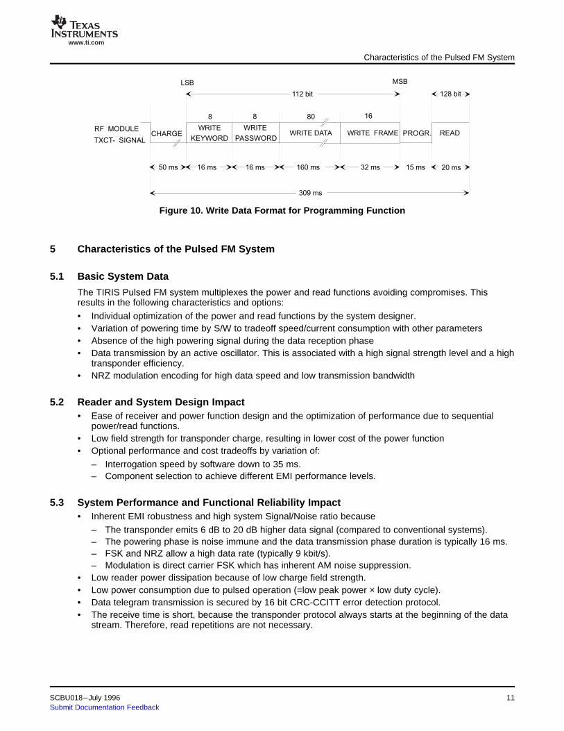
Figure 10. Write Data Format for Programming Function
The TIRIS Pulsed FM system multiplexes the power and read functions avoiding compromises. Thisresults in the following characteristics and options:
• Individual optimization of the power and read functions by the system designer.• Variation of powering time by S/W to tradeoff speed/current consumption with other parameters• Absence of the high powering signal during the data reception phase• Data transmission by an active oscillator. This is associated with a high signal strength level and a high
transponder efficiency.• NRZ modulation encoding for high data speed and low transmission bandwidth
• Ease of receiver and power function design and the optimization of performance due to sequentialpower/read functions.
• Low field strength for transponder charge, resulting in lower cost of the power function• Optional performance and cost tradeoffs by variation of:
– Interrogation speed by software down to 35 ms.– Component selection to achieve different EMI performance levels.
• Inherent EMI robustness and high system Signal/Noise ratio because
– The transponder emits 6 dB to 20 dB higher data signal (compared to conventional systems).– The powering phase is noise immune and the data transmission phase duration is typically 16 ms.– FSK and NRZ allow a high data rate (typically 9 kbit/s).– Modulation is direct carrier FSK which has inherent AM noise suppression.
• Low reader power dissipation because of low charge field strength.• Low power consumption due to pulsed operation (=low peak power × low duty cycle).• Data telegram transmission is secured by 16 bit CRC-CCITT error detection protocol.• The receive time is short, because the transponder protocol always starts at the beginning of the data
stream. Therefore, read repetitions are not necessary.
SCBU018–July 1996 xxx 11Submit Documentation Feedback
www.ti.com
5.4 Other Quality Factors of the TIRIS Pulsed FM System
6 EMI/EMC Performance
6.1 General
6.2 The Automotive Environment and Factors
6.3 TIRIS Pulsed FM Transponder and System Performance
EMI/EMC Performance
• High and consistent transponder product quality and performance by automated high volumemanufacturing.
• The direct FSK provides enhanced separation and better position-selective reading of adjacenttransponders compared to AM systems.
• Product migration path concept from RO to R/W to Password protected and Multipage transponders.The reader or system can be changed from RO to R/W by S/W change only.
• TIRIS transponders are 100% tested according to the procedures of TI's Total Quality Culture• The reliability of TIRIS transponders is monitored through the following tests: temperature and
humidity, thermal shock, and operating life.
For any RFiD system, the EMI/EMC performance is determined by three factors:
1. The reader design and the resulting noise immunity performance2. The signal strength of the transponder and Signal/Noise ratio at the receiver input3. The transponder immunity to EM fields:
• The most critical EMI factor or component in a system is the reader immunity.• A high transponder data signal facilitates reader design through the higher Signal/Noise. ratio• The least critical component is the transponder. Immunity levels are generally very high.
All EMI sources can be classified into three different categories:
1. Broad band "industrial" noise of sporadic or continuous nature2. Discrete radio frequency signals unmodulated or FM /FSK modulated3. Discrete radio frequency signals which are AM or ASK modulated.
In an automotive environment all noise types are present and potentially cause EMI problems.
Especially the increased application of electronics and communication systems in cars employing digitaland ASK type modulation techniques can produce and emit high field strength levels.
The highest energy noise sources are in the low frequency part of the spectrum at frequencies from a fewcycles up to a few kHz. The sources are actuators, solenoid switching, ignition, motors, control circuitryand so on. They pollute the car environment, either by direct emission, or by induction, or by conductedradiation.
Above 10 kHz, the noise levels decay quickly at a rate of 20 dB to 40 dB/octave. RFiD systems emittingand receiving data signals at these or higher frequencies are less affected by EMI.
EMI measurement procedures which are most currently cited (for example, the DIN 40839/part4) areinappropriate to:
• Determine a realistic RFiD system behavior for an automotive environment• Determine the EMI performance and threshold of transponder• Test systems at worst case (low frequency) conditions.
However, the TIRIS transponder meets and exceeds the DIN40839/part4.
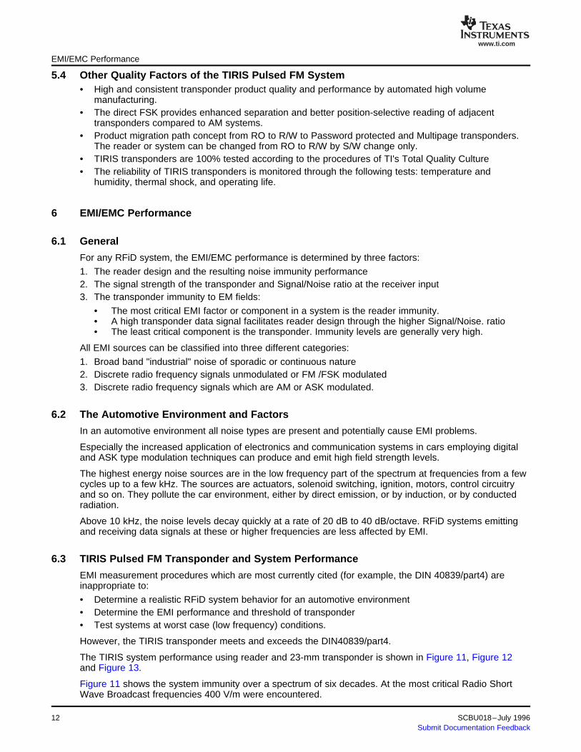
The TIRIS system performance using reader and 23-mm transponder is shown in Figure 11, Figure 12and Figure 13.
Figure 11 shows the system immunity over a spectrum of six decades. At the most critical Radio ShortWave Broadcast frequencies 400 V/m were encountered.
12 xxx SCBU018–July 1996Submit Documentation Feedback
www.ti.com
0.001 0.01 0.1 1 10 1,000
0.001
0.01
0.1
1
10
100
1,000
10,000
FREQUENCY (MHz)
LW SWMW FM VHF / UHF
Malfunction
Function Function
EM
I F
IEL
D S
TR
EN
GT
H(V
OLT
S/m
)
1 2 5 10 20 50 100 200 500 1,000
0
20
40
60
80
100
120
430
MHz 145
MHz
900
MHz
ELECTRICAL FIELD STRENGTH (VOLTS/m)
RE
AD
ING
RA
NG
E (
%)
NO
RM
AL
IZE
D
EMI/EMC Performance
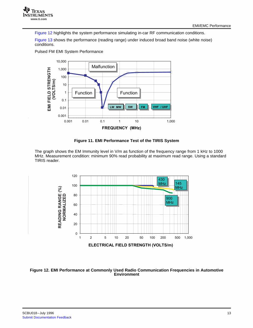
Figure 12 highlights the system performance simulating in-car RF communication conditions.
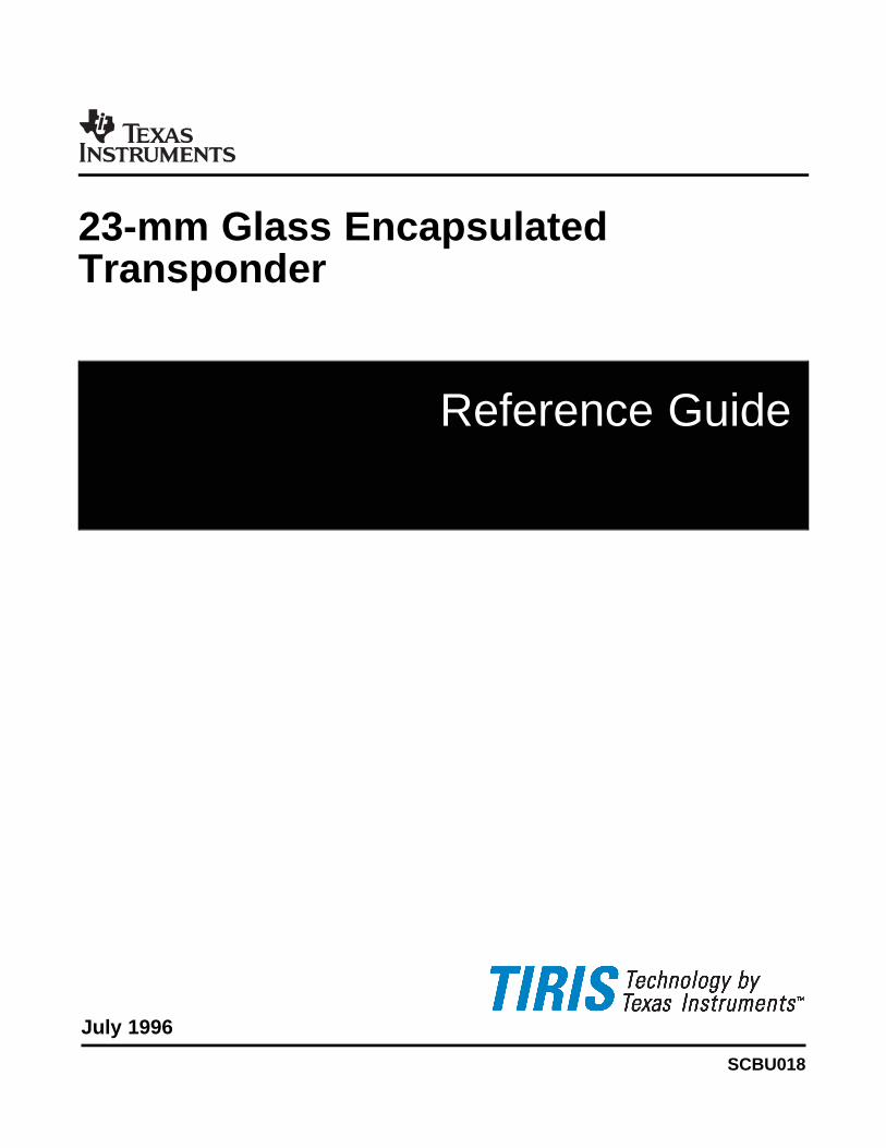
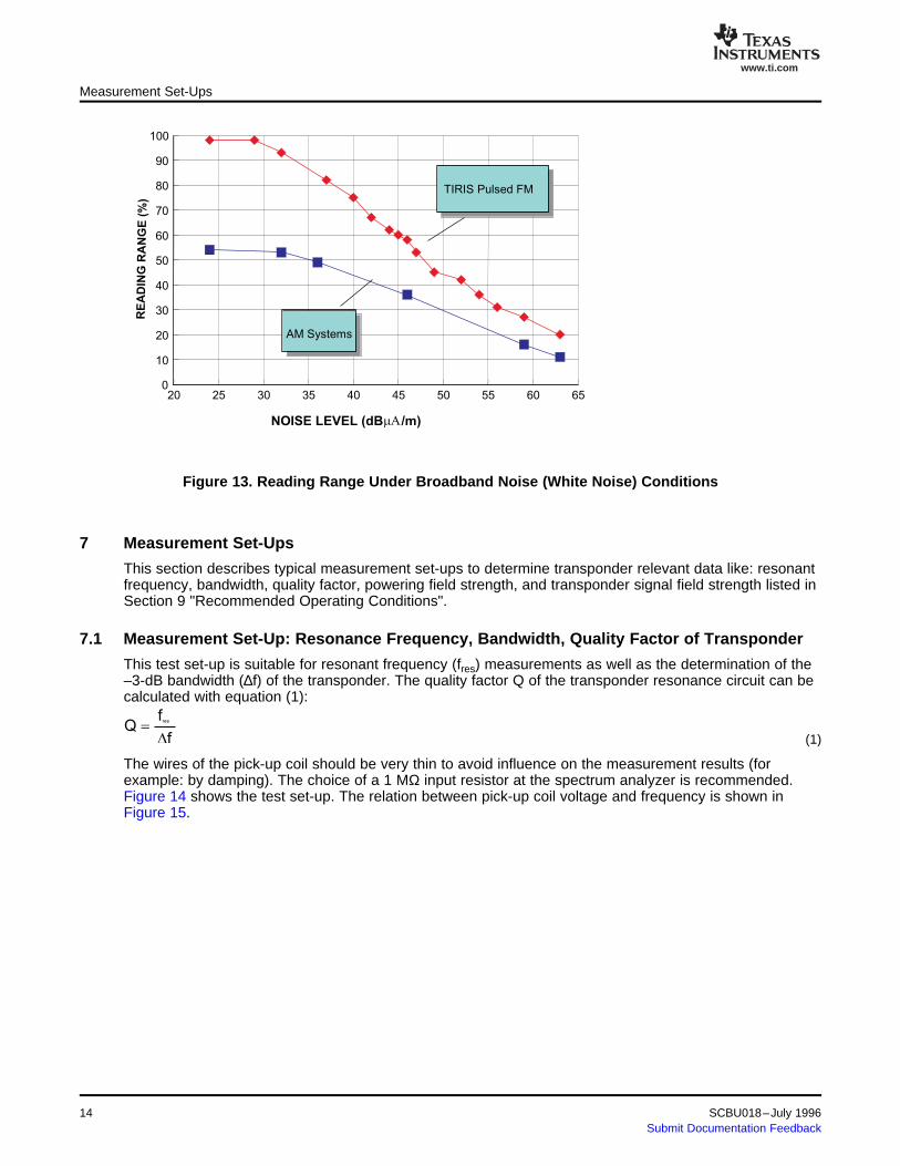
Figure 13 shows the performance (reading range) under induced broad band noise (white noise)conditions.
Pulsed FM EMI System Performance
Figure 11. EMI Performance Test of the TIRIS System
The graph shows the EM Immunity level in V/m as function of the frequency range from 1 kHz to 1000MHz. Measurement condition: minimum 90% read probability at maximum read range. Using a standardTIRIS reader.
Figure 12. EMI Performance at Commonly Used Radio Communication Frequencies in AutomotiveEnvironment
SCBU018–July 1996 xxx 13Submit Documentation Feedback
www.ti.com
20 25 30 35 40 45 50 55 60 650
10
20
30
40
50
60
70
80
90
100
NOISE LEVEL (dBmA/m)
AM Systems
TIRIS Pulsed FM
RE
AD
ING
RA
NG
E(%
)
7 Measurement Set-Ups
7.1 Measurement Set-Up: Resonance Frequency, Bandwidth, Quality Factor of Transponder
resf
Qf
=D (1)
Measurement Set-Ups
Figure 13. Reading Range Under Broadband Noise (White Noise) Conditions
This section describes typical measurement set-ups to determine transponder relevant data like: resonantfrequency, bandwidth, quality factor, powering field strength, and transponder signal field strength listed inSection 9 "Recommended Operating Conditions".
This test set-up is suitable for resonant frequency (fres) measurements as well as the determination of the–3-dB bandwidth (∆f) of the transponder. The quality factor Q of the transponder resonance circuit can becalculated with equation (1):
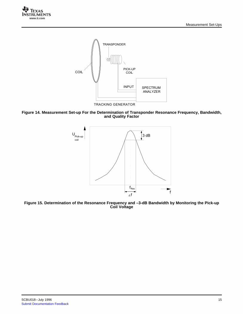
The wires of the pick-up coil should be very thin to avoid influence on the measurement results (forexample: by damping). The choice of a 1 MΩ input resistor at the spectrum analyzer is recommended.Figure 14 shows the test set-up. The relation between pick-up coil voltage and frequency is shown inFigure 15.
14 xxx SCBU018–July 1996Submit Documentation Feedback
www.ti.com
PICK-UP
COIL
SPECTRUM
ANALYZER
COIL
INPUT
TRACKING GENERATOR
TRANSPONDER
3 dB
fRes
f
UPick-up
coil
f
Measurement Set-Ups
Figure 14. Measurement Set-up For the Determination of Transponder Resonance Frequency, Bandwidth,and Quality Factor
Figure 15. Determination of the Resonance Frequency and –3-dB Bandwidth by Monitoring the Pick-upCoil Voltage
SCBU018–July 1996 xxx 15Submit Documentation Feedback
www.ti.com
7.2 Measurement Set-Up: Powering Field Strength
ANTENNA AXIS
PICK-UP
COILSIGNAL
GENERATOR
d/2
d
COILS
OSCILLOSCOPETrigger
TRANSPONDER
o r0 r
4 4 N IB H
5 5 d/ 2
×m m × ×= × × = m × m ×
(2)
Measurement Set-Ups
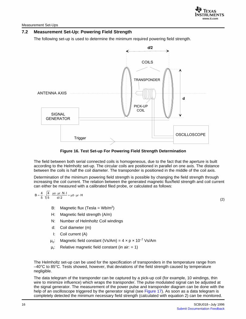
The following set-up is used to determine the minimum required powering field strength.
Figure 16. Test Set-up For Powering Field Strength Determination
The field between both serial connected coils is homogeneous, due to the fact that the aperture is builtaccording to the Helmholtz set-up. The circular coils are positioned in parallel on one axis. The distancebetween the coils is half the coil diameter. The transponder is positioned in the middle of the coil axis.
Determination of the minimum powering field strength is possible by changing the field strength throughincreasing the coil current. The relation between the generated magnetic flux/field strength and coil currentcan either be measured with a calibrated filed probe, or calculated as follows:
B: Magnetic flux (Tesla = Wb/m2)
H: Magnetic field strength (A/m)
N: Number of Helmholtz Coil windings
d: Coil diameter (m)
I: Coil current (A)
µo: Magnetic field constant (Vs/Am) = 4 × p × 10–7 Vs/Am
µr: Relative magnetic field constant (in air: = 1)
The Helmholtz set-up can be used for the specification of transponders in the temperature range from–40°C to 85°C. Tests showed, however, that deviations of the field strength caused by temperaturenegligible.
The data telegram of the transponder can be captured by a pick-up coil (for example, 10 windings, thinwire to minimize influence) which wraps the transponder. The pulse modulated signal can be adjusted atthe signal generator. The measurement of the power pulse and transponder diagram can be done with thehelp of an oscilloscope triggered by the generator signal (see Figure 17). As soon as a data telegram iscompletely detected the minimum necessary field strength (calculated with equation 2) can be monitored.
16 xxx SCBU018–July 1996Submit Documentation Feedback
www.ti.com
Response phase
max 20msec
U
tPower
phase
7.3 Measurement Set-Up: Transponder Signal Strength
ANTENNA AXIS
PICK-UP
COIL
SIGNAL
GENERATOR
d
COILS
SPECTRUM
ANALYZER
TRANSPONDER
Measurement Set-Ups
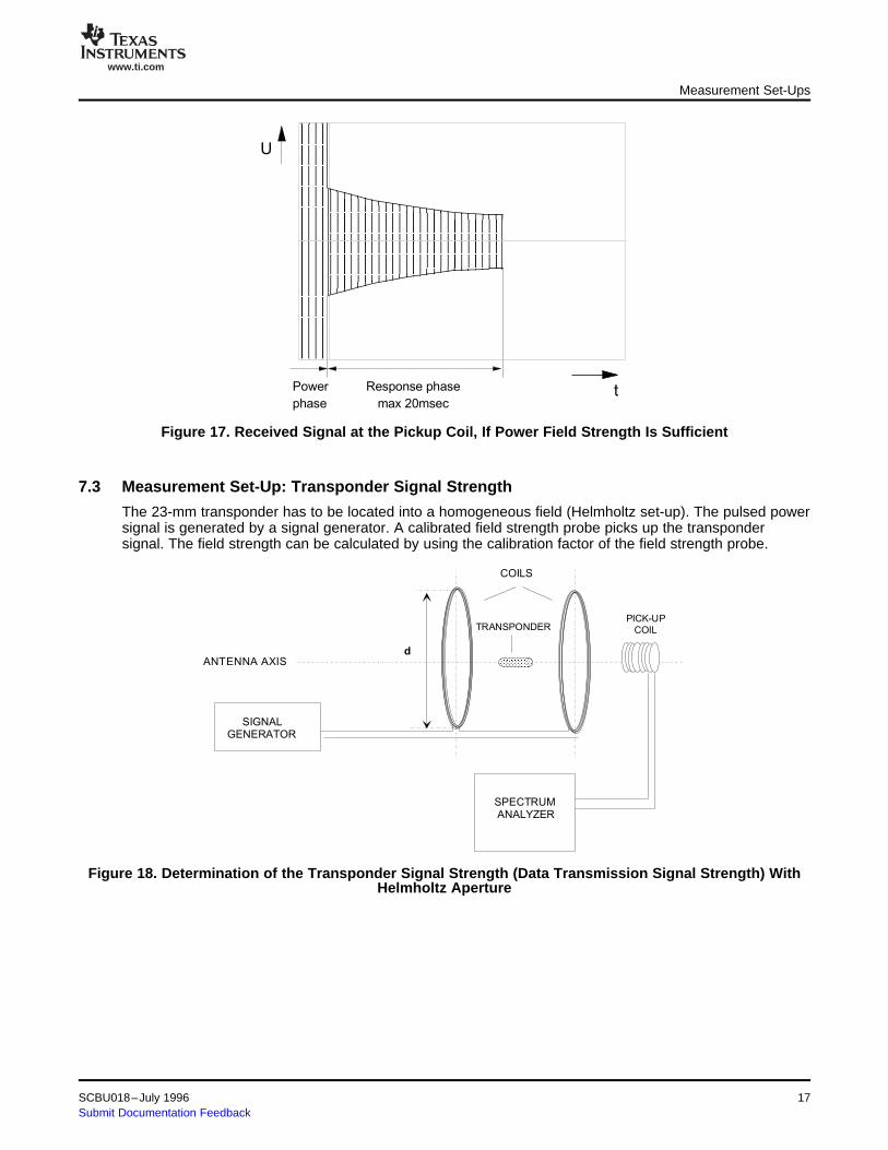
Figure 17. Received Signal at the Pickup Coil, If Power Field Strength Is Sufficient
The 23-mm transponder has to be located into a homogeneous field (Helmholtz set-up). The pulsed powersignal is generated by a signal generator. A calibrated field strength probe picks up the transpondersignal. The field strength can be calculated by using the calibration factor of the field strength probe.
Figure 18. Determination of the Transponder Signal Strength (Data Transmission Signal Strength) WithHelmholtz Aperture
SCBU018–July 1996 xxx 17Submit Documentation Feedback
www.ti.com
P o w e r
p h a s e
R e a d
p h a s e
U
t
T ra n s p o n d e r s ig n a lP o w e r s ig n a l
N o is e
8 Absolute Maximum Ratings
9 Recommended Operating Conditions
10 Characteristics
Absolute Maximum Ratings
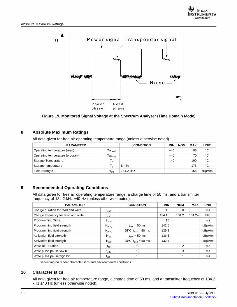
Figure 19. Monitored Signal Voltage at the Spectrum Analyzer (Time Domain Mode)
All data given for free air operating temperature range (unless otherwise noted).
PARAMETER CONDITION MIN NOM MAX UNIT
Operating temperature (read) Taread –40 85 °C
Operating temperature (program) TaProg –40 70 °C
Storage Temperature Ts –40 100 °C
Storage temperature Ts 5 min 175 °C
Field Strength Hexc 134.2 kHz 168 dBµV/m
All data given for free air operating temperature range, a charge time of 50 ms, and a transmitterfrequency of 134.2 kHz ±40 Hz (unless otherwise noted).
PARAMETER CONDITION MIN NOM MAX UNIT
Charge duration for read and write texc 15 50 ms
Charge frequency for read and write fexc 134.16 134.2 134.24 kHz
Programming Time tprog 15 ms
Programming field strength Hprog texc = 50 ms 142.5 dBµA/m
Programming field strength Hprog 25°C, texc = 50 ms 139.5 dBµA/m
Activation field strength Hact texc = 50 ms 136.5 dBµA/m
Activation field strength Hact 25°C, texc = 50 ms 132.5 dBµA/m
Write Bit Duration tbit(1) 2 ms
Write pulse pause/low bit toffL(1) 0.3 ms
Write pulse pause/high bit toffH(1) 1 ms
(1) Depending on reader characteristics and environmental conditions.
All data given for free air temperature range, a charge time of 50 ms, and a transmitter frequency of 134.2kHz ±40 Hz (unless otherwise noted).
xxx18 SCBU018–July 1996Submit Documentation Feedback
www.ti.com
11 Environmental Data and Reliability
12 Memory
13 Package
Environmental Data and Reliability
PARAMETER CONDITION MIN NOM MAX UNIT
Operating quality factor Qop (1) 62
Low bit transmit frequency fL 131.5 139 kHz
Low bit transmit frequency fL 25°C 132.2 134.3 136.2 kHz
Low bit duration tL 0.115 0.119 0.121 ms
High bit transmit frequency fH 120 128 kHz
High bit transmit frequency fH 25°C 121 122.9 125 kHz
High bit duration tH 0.125 0.130 0.133 ms
Transponder output field strength at 5 cm Hout 80 101 dBµA/m
FSK modulation index (read); fL– fH mread 25°C 11 kHz
FSK modulation index (read); fL– fH mread(2) 9 15 kHz
Data transmission rate (read) rread 7.4 8.7 kbit/s
Data transmission time (read) rread 16 20 ms
ASK modulation index (write) mwrite 100 %
Data transmission rate (write) rwrite(3) 0.5 kbit/s
Data transmission time (write) twrite(3) 224 ms
(1) Specified Qop must be met in the application over the required temperature range. Refer to the test set-up shown in Figure 14.(2) Maintained over specified temperature range.(3) Adaptable to application.
PARAMETER CONDITION MIN NOM MAX UNIT
Programming cycles (1) 25°C 100 k cycles
Data retention time (1) 100k cycles at 25°C storage temperature 10 years
EM radiation immunity 1 MHz to 512 MHz 100 V/m
EM radiation immunity 512 MHz to 1000 MHz 50 V/m
ESD immunity IEC 801-2 2 kV
X-ray dose 2000 RAD
Vibration (2) IEC 68-2-6, Test Fc
Shock IEC 68-2-27, Test Ea
(1) Cumulative failure rate 1%.(2) f = 10 Hz – 2000 Hz.
PARAMETER DATA
Memory size 80 bits
Memory organization 1 block
Identification data 64 bit
Error detection (Data BCC) CRC – CCITT, 16 bit
PARAMETER DATA
Dimensions 23 mm × 3.85 mm (see Figure 3)
Weight 0.6 g
SCBU018–July 1996 xxx 19Submit Documentation Feedback
www.ti.com
14 Packing Symbolization
MALAYSIA
xxxxxxxxxxxxxxxx
Packing Symbolization
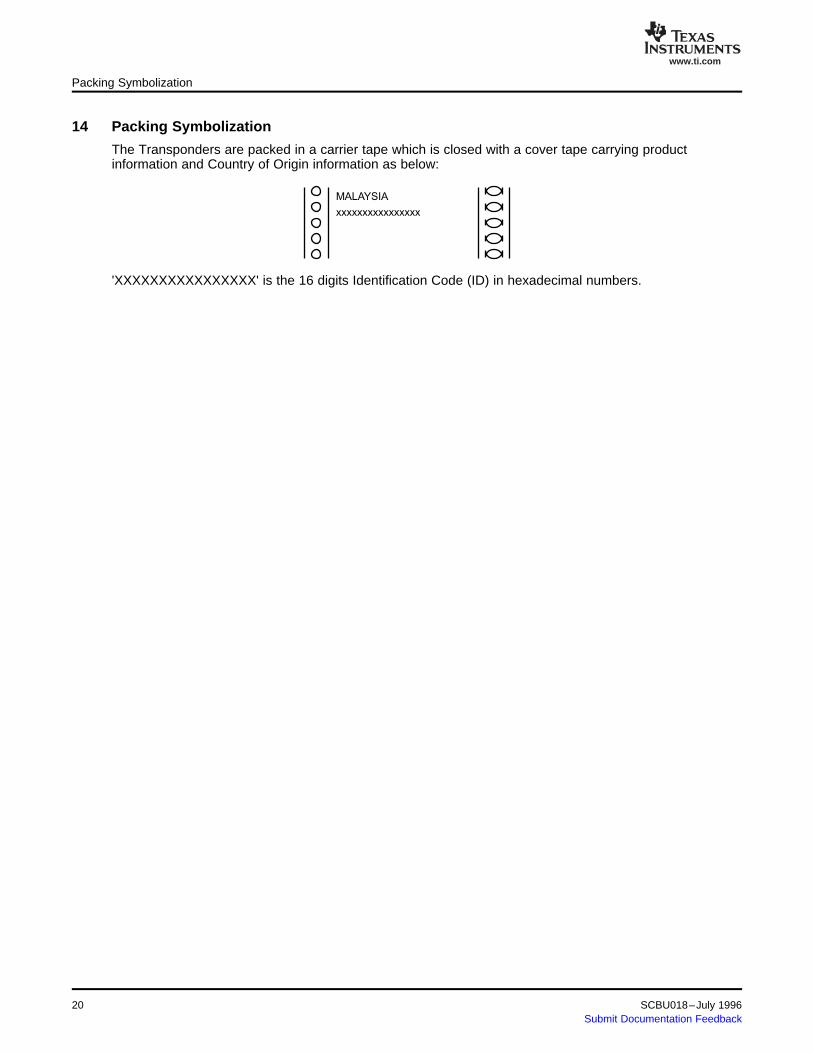
The Transponders are packed in a carrier tape which is closed with a cover tape carrying productinformation and Country of Origin information as below:
'XXXXXXXXXXXXXXXX' is the 16 digits Identification Code (ID) in hexadecimal numbers.
20 xxx SCBU018–July 1996Submit Documentation Feedback

www.ti.com
Appendix A Conversion Formula
H =E
dB V / m
dB A
mmm
-é
ëê
ù
ûú51 5.
H =dB A
m
m
EdB V
m=
m
Appendix A
Conversion formula between magnetic flux, magnetic field strength and electric field strength.
B = µ0 • H
E = ZF• H
;
;
B = Magnetic flux [Tesla = Wb/m2 =Vs/m2]; 1 mWb/m2 = 0.795 A/m
H = Magnetic field strength (A/m or in logarithmic term dBµA/m)
E = electrical field strength (V/m or in logarithmic term dBµV/m)
µo = Magnetic field constant = 1.257 × 10⁻⁶ Vs/Am
Zr = Free space impedance = 120 πΩ = 377 Ω
SCBU018–July 1996 Conversion Formula 21Submit Documentation Feedback

IMPORTANT NOTICE
Texas Instruments Incorporated and its subsidiaries (TI) reserve the right to make corrections, modifications,enhancements, improvements, and other changes to its products and services at any time and to discontinueany product or service without notice. Customers should obtain the latest relevant information before placingorders and should verify that such information is current and complete. All products are sold subject to TI’s termsand conditions of sale supplied at the time of order acknowledgment.
TI warrants performance of its hardware products to the specifications applicable at the time of sale inaccordance with TI’s standard warranty. Testing and other quality control techniques are used to the extent TIdeems necessary to support this warranty. Except where mandated by government requirements, testing of allparameters of each product is not necessarily performed.
TI assumes no liability for applications assistance or customer product design. Customers are responsible fortheir products and applications using TI components. To minimize the risks associated with customer productsand applications, customers should provide adequate design and operating safeguards.
TI does not warrant or represent that any license, either express or implied, is granted under any TI patent right,copyright, mask work right, or other TI intellectual property right relating to any combination, machine, or processin which TI products or services are used. Information published by TI regarding third-party products or servicesdoes not constitute a license from TI to use such products or services or a warranty or endorsement thereof.Use of such information may require a license from a third party under the patents or other intellectual propertyof the third party, or a license from TI under the patents or other intellectual property of TI.
Reproduction of information in TI data books or data sheets is permissible only if reproduction is withoutalteration and is accompanied by all associated warranties, conditions, limitations, and notices. Reproductionof this information with alteration is an unfair and deceptive business practice. TI is not responsible or liable forsuch altered documentation.
Resale of TI products or services with statements different from or beyond the parameters stated by TI for thatproduct or service voids all express and any implied warranties for the associated TI product or service andis an unfair and deceptive business practice. TI is not responsible or liable for any such statements.
Following are URLs where you can obtain information on other Texas Instruments products and applicationsolutions:
Products Applications
Amplifiers amplifier.ti.com Audio www.ti.com/audio
Data Converters dataconverter.ti.com Automotive www.ti.com/automotive
DSP dsp.ti.com Broadband www.ti.com/broadband
Interface interface.ti.com Digital Control www.ti.com/digitalcontrol
Logic logic.ti.com Military www.ti.com/military
Power Mgmt power.ti.com Optical Networking www.ti.com/opticalnetwork
Microcontrollers microcontroller.ti.com Security www.ti.com/security
Low Power Wireless www.ti.com/lpw Telephony www.ti.com/telephony
Video & Imaging www.ti.com/video
Wireless www.ti.com/wireless
Mailing Address: Texas Instruments
Post Office Box 655303 Dallas, Texas 75265
Copyright 2006, Texas Instruments Incorporated