Embed Size (px)
Citation preview
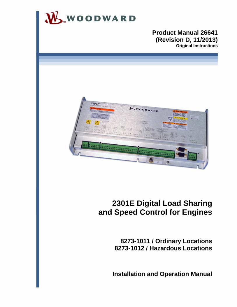
Product Manual 26641(Revision D, 11/2013)
Original Instructions
2301E Digital Load Sharing and Speed Control for Engines
8273-1011 / Ordinary Locations 8273-1012 / Hazardous Locations
Installation and Operation Manual
General Precautions
Read this entire manual and all other publications pertaining to the work to be performed before installing, operating, or servicing this equipment.
Practice all plant and safety instructions and precautions.
Failure to follow instructions can cause personal injury and/or property damage.
Revisions
This publication may have been revised or updated since this copy was produced. To verify that you have the latest revision, check manual 26311 , Revision Status & Distribution Restrictions of Woodward Technical Publications, on the publications page of the Woodward website:
www.woodward.com/publications The latest version of most publications is available on the publications page. If your publication is not there, please contact your customer service representative to get the latest copy.
Proper Use
Any unauthorized modifications to or use of this equipment outside its specified mechanical, electrical, or other operating limits may cause personal injury and/or property damage, including damage to the equipment. Any such unauthorized modifications: (i) constitute "misuse" and/or "negligence" within the meaning of the product warranty thereby excluding warranty coverage for any resulting damage, and (ii) invalidate product certifications or listings.
Translated Publications
If the cover of this publication states "Translation of the Original Instructions" please note:
The original source of this publication may have been updated since this translation was made. Be sure to check manual 26311 , Revision Status & Distribution Restrictions of Woodward Technical Publications, to verify whether this translation is up to date. Out-of-date translations are marked with . Always compare with the original for technical specifications and for proper and safe installation and operation procedures.
Revisions—Changes in this publication since the last revision are indicated by a black line
alongside the text. Woodward reserves the right to update any portion of this publication at any time. Information provided by Woodward is believed to be correct and reliable. However, no responsibility is assumed by Woodward unless otherwise expressly undertaken.
Manual 26641 Copyright © Woodward 2012–2013
All Rights Reserved
Manual 26641 2301E Digital Control
Woodward i
Contents
WARNINGS AND NOTICES ............................................................................ V
ELECTROSTATIC DISCHARGE AWARENESS ................................................. VI
REGULATORY COMPLIANCE .......................................................................VII
CHAPTER 1. GENERAL INFORMATION ........................................................... 1 Description .............................................................................................................. 1 Applications ............................................................................................................ 2 Control Options ....................................................................................................... 3 References ............................................................................................................. 3
CHAPTER 2. INSTALLATION .......................................................................... 9 Introduction ............................................................................................................. 9 Unpacking ............................................................................................................... 9 Power Requirements .............................................................................................. 9 Location Considerations ....................................................................................... 10 Electrical Connections .......................................................................................... 10 Shields and Grounding ......................................................................................... 11 LED System Status Indicators .............................................................................. 11 Setting Speed Range ........................................................................................... 12 Potential Transformer Connections (Terminals 1–3) ........................................... 12 Current Transformer Connections (Terminals 4–9) ............................................. 12 Real Power Load Calculation ............................................................................... 12 Load Share Lines (Terminals 10–12) ................................................................... 12 Power Supply (Terminals 48–50) ......................................................................... 13 Discrete Inputs (Terminals 34–41) ....................................................................... 14 Close to Run or Minimum Fuel (Terminal 34) ...................................................... 15 Discrete Inputs B, C, D (Terminals 35, 36, 37) ..................................................... 15 Failed Speed Override .......................................................................................... 16 Reset .................................................................................................................... 16 Select 2nd Dynamics ............................................................................................. 16 Shutdown External ............................................................................................... 16 Idle / Rated Speed ................................................................................................ 17 Idle/Rated Software Switch .................................................................................. 17 CB Aux/Droop Contact ......................................................................................... 17 Derate KW Load Reference ................................................................................. 18 Raise Speed/Load Contact (Terminal 38) ............................................................ 19 Lower Speed/Load Contact (Terminal 39) ........................................................... 19 Remote Speed Setting (Both Raise and Lower Contacts; Terminals 38 and 39) 19 Load Generator (Terminal 40) .............................................................................. 20 Base Load (Terminal 41) ...................................................................................... 20 Actuator Output (Terminals 13–15) ...................................................................... 20 Analog Inputs (Terminals 19–24) ......................................................................... 20 Analog Input #1 (Terminals 19-20) ....................................................................... 22 Analog Input #2 (Terminals 22-23) ....................................................................... 22 Speed Sensor (Terminals 25-26) ......................................................................... 23 Relay Driver Outputs (Terminals 42, 43, & 44–48) .............................................. 23 4–20 mA Output (Terminals 16–17) ..................................................................... 24 Communication Ports ........................................................................................... 24 Installation Check-out Procedure ......................................................................... 28
2301E Digital Control Manual 26641
ii Woodward
Contents
CHAPTER 3. DESCRIPTION OF OPERATION.................................................. 29 Introduction ........................................................................................................... 29 Speed Control ....................................................................................................... 29 Control Dynamics ................................................................................................. 30 Minimum Fuel Function ........................................................................................ 31 Maximum Fuel Function ....................................................................................... 32 Start Limit Function ............................................................................................... 32 Torque Limiter ....................................................................................................... 32 Manifold Air Pressure Limiter ............................................................................... 33 Speed/Load Reference and Ramps ..................................................................... 33 Speed Reference and Ramp Functions ............................................................... 33 Speed Bias and Synchronizer Summing .............................................................. 35 Load Reference and Ramp Functions .................................................................. 35 Droop Function ..................................................................................................... 37 Droop/Isochronous Load Sharing on an Isolated Bus .......................................... 41 Isochronous Load Sharing on an Isolated Bus ..................................................... 42 Actuator Droop ...................................................................................................... 42 Load Pulse / Load Rejection ................................................................................. 43
CHAPTER 4. ENTERING CONTROL SET POINTS ........................................... 44 Introduction ........................................................................................................... 44 Control Assistant PC Interface ............................................................................. 44 2301E Toolkit Service Tool ................................................................................... 54 Entering the Configure Mode ................................................................................ 63 Configure Menu Descriptions ............................................................................... 63 Exiting the Configure Mode .................................................................................. 72 Service Menu Descriptions ................................................................................... 72 Saving the Tunable Values .................................................................................107
CHAPTER 5. INITIAL CONTROL SETTINGS .................................................. 108 Initial Prestart Settings ........................................................................................108 Start-up Adjustments ..........................................................................................108 Adjust for Stable Operation ................................................................................109 Dynamic Adjustment ...........................................................................................110 Actuator Compensation Adjustment ...................................................................110 Ramp Time Adjustment ......................................................................................110 Raise/Lower Time Adjustment ............................................................................110 Start Fuel Limit Adjustment ................................................................................111 Speed Sensor Check ..........................................................................................111 Current Transformer (CT) Phasing Check .........................................................111 Phase Correction Procedure ..............................................................................112 Load Calibration Adjustment ..............................................................................115 Droop Adjustment ...............................................................................................115
CHAPTER 6. ALTERNATE DYNAMIC ADJUSTMENTS ................................... 116 Introduction .........................................................................................................116 Adjustment ..........................................................................................................116
CHAPTER 7. TROUBLESHOOTING ............................................................. 121 Introduction .........................................................................................................121 Troubleshooting Procedure ................................................................................121 Control Start-up ..................................................................................................121 Control Test and Calibration ...............................................................................122 Troubleshooting Charts ......................................................................................123
Manual 26641 2301E Digital Control
Woodward iii
Contents
CHAPTER 8. COMMUNICATIONS ............................................................... 128 Modbus Communication ..................................................................................... 128 Monitor Only ....................................................................................................... 128 Monitor and Control ............................................................................................ 128 Modbus Communication Mode ........................................................................... 129 Modbus Function Codes ..................................................................................... 130 Port Adjustments ................................................................................................ 130 2301E Control Modbus Addresses ..................................................................... 131 Modbus Scale Factors ........................................................................................ 132 Shutdown Command through Modbus ............................................................... 132 Start Command through Modbus ....................................................................... 133 For More Modbus Information ............................................................................ 133
CHAPTER 9. PRODUCT SUPPORT AND SERVICE OPTIONS ......................... 134 Product Support Options .................................................................................... 134 Product Service Options ..................................................................................... 134 Returning Equipment for Repair ......................................................................... 135 Replacement Parts ............................................................................................. 135 Engineering Services .......................................................................................... 136 Contacting Woodward’s Support Organization .................................................. 136 Technical Assistance .......................................................................................... 137
APPENDIX A. SERVICE/CONFIGURATION CHART ....................................... 138 Configure Menus ................................................................................................ 138 Service Menus .................................................................................................... 139
APPENDIX B. PID EXAMPLES .................................................................. 146 PID Conversion Charts ....................................................................................... 147
APPENDIX C. MODBUS COMMUNICATION LIST .......................................... 149
APPENDIX D. SOFTWARE REVISION ......................................................... 152
APPENDIX E. PRINTING OUT A DATALOG ................................................. 154
APPENDIX F. QUICK ENGINE START GUIDE .............................................. 155
APPENDIX G. LOADING THE SETTINGS FILE FROM A 2301D TO A 2301E ... 157
APPENDIX H. 2301E CONTROL SPECIFICATIONS ...................................... 159
REVISION HISTORY .................................................................................. 160
DECLARATIONS ....................................................................................... 161
The following are trademarks of Woodward, Inc.: DSLC easYgen The following are trademarks of their respective companies: Modbus (Schneider Automation Inc.)

2301E Digital Control Manual 26641
iv Woodward
Illustrations and Tables Figure 1-1a. 2301E Outline Drawing (Ordinary Locations) .................................... 4 Figure 1-1b. 2301E Outline Drawing (Hazardous Locations) ................................. 5 Figure 1-2a. 2301E Control Wiring Diagram (sheet 1) ........................................... 6 Figure 1-2b. 2301E Control Wiring Diagram (sheet 2) ........................................... 7 Figure 1-2c. 2301E Control Wiring Diagram (notes) .............................................. 8 Figure 2-1. Installation of Wiring into Terminal ..................................................... 11 Figure 2-2. Droop Contact and Circuit Breaker Auxiliary Contact ........................ 18 Figure 2-3. RS-232 Pin assignments for Serial Communication Cable ............... 25 Figure 2-4. Typical RS-422 Communications Connections ................................. 25 Figure 2-5. RS-422 Terminator Locations ............................................................ 26 Figure 2-6. Preferred Multipoint Wiring Using Shielded Twisted-pair Cable with a
Separate Signal Ground Wire .......................................................... 27 Figure 2-7. Alternate Multipoint Wiring Using Shielded Twisted-pair Cable without
a Separate Signal Ground Wire ....................................................... 27 Figure 3-1. Speed Control System ....................................................................... 30 Figure 3-2. Start Limit Function ............................................................................ 32 Figure 3-3. Remote Speed Reference ................................................................. 34 Figure 3-4. Paralleling System ............................................................................. 38 Figure 3-5. Droop Mode ....................................................................................... 39 Figure 3-6. Isochronous Mode .............................................................................. 40 Figure 3-7. Droop/Isochronous Load Sharing ...................................................... 41 Figure 3-8. Isochronous Load Sharing ................................................................. 41 Figure 4-1. Null Modem Cable .............................................................................. 45 Figure 4-1. Null Modem Cable .............................................................................. 54 Figure 4-2. Control Gain as a Function of Speed Error ........................................ 80 Figure 4-3. Control Gain as a Function of Fuel Demand (Load) .......................... 81 Figure 4-4. Speed Filter ........................................................................................ 82 Figure 4-5. Typical Transient Response Curves .................................................. 83 Figure 4-6. Non-linear Valve Power Curve ........................................................... 88 Figure 4-7. Non-linear Valve Power Curve for Turbocharged Engine .................. 88 Figure 4-8. Linearized Gain Plot ........................................................................... 89 Figure 4-9. Start Limit Function ............................................................................ 91 Figure 4-10. Soft Start Fuel Limit Function ........................................................... 92 Figure 4-11. Torque Limiter Function ................................................................... 93 Figure 4-12. MAP Limiter Function ....................................................................... 95 Figure 5-1. Temporary Wiring for Transformer Phase Correction ......................113 Figure 5-2. Droop Adjustment ............................................................................115 Figure 6-1. Trend Tool Trace Example 1 ...........................................................117 Figure 6-2. Trend Tool Trace Example 2 ...........................................................118 Figure 6-3. Trend Tool Trace Example 3 ...........................................................118 Figure 6-4. Trend Tool Trace Example 4 ...........................................................119 Figure 6-5. Trend Tool Trace Example 5 ...........................................................119 Figure 6-6. Trend Tool Trace Example 6 ...........................................................119 Figure B-1. Gain Potentiometer Conversion Chart .............................................147 Figure B-2. Reset Potentiometer Conversion Chart ...........................................147 Figure B-3. Actuator Compensation Potentiometer Conversion Chart ..............148 Table 3-1. Description of Discrete Inputs While in Load Control .......................... 37 Table 8-1. RTU Modbus .....................................................................................129 Table 8-2. Modbus Frame Definition ..................................................................129 Table 8-3. Modbus Function Codes ...................................................................130 Table 8-4. Port Adjustments ...............................................................................130 Table B-1. PID Examples ...................................................................................146

Manual 26641 2301E Digital Control
Woodward v
Warnings and Notices Important Definitions
This is the safety alert symbol. It is used to alert you to potential personal injury hazards. Obey all safety messages that follow this symbol to avoid possible injury or death.
DANGER—Indicates a hazardous situation which, if not avoided, will result in death or serious injury.
WARNING—Indicates a hazardous situation which, if not avoided, could result in death or serious injury.
CAUTION—Indicates a hazardous situation which, if not avoided, could result in minor or moderate injury.
NOTICE—Indicates a hazard that could result in property damage only (including damage to the control).
IMPORTANT—Designates an operating tip or maintenance suggestion.
Overspeed / Overtemperature /
Overpressure
The engine, turbine, or other type of prime mover should be equipped with an overspeed shutdown device to protect against runaway or damage to the prime mover with possible personal injury, loss of life, or property damage.
The overspeed shutdown device must be totally independent of the prime mover control system. An overtemperature or overpressure shutdown device may also be needed for safety, as appropriate.
Personal Protective Equipment
The products described in this publication may present risks that could lead to personal injury, loss of life, or property damage. Always wear the appropriate personal protective equipment (PPE) for the job at hand. Equipment that should be considered includes but is not limited to: Eye Protection Hearing Protection Hard Hat Gloves Safety Boots Respirator
Always read the proper Material Safety Data Sheet (MSDS) for any working fluid(s) and comply with recommended safety equipment.
Start-up
Be prepared to make an emergency shutdown when starting the engine, turbine, or other type of prime mover, to protect against runaway or overspeed with possible personal injury, loss of life, or property damage.
Automotive Applications
On- and off-highway Mobile Applications: Unless Woodward's control functions as the supervisory control, customer should install a system totally independent of the prime mover control system that monitors for supervisory control of engine (and takes appropriate action if supervisory control is lost) to protect against loss of engine control with possible personal injury, loss of life, or property damage.

2301E Digital Control Manual 26641
vi Woodward
Battery Charging Device
To prevent damage to a control system that uses an alternator or battery-charging device, make sure the charging device is turned off before disconnecting the battery from the system.
Electrostatic Discharge Awareness
Electrostatic Precautions
Electronic controls contain static-sensitive parts. Observe the following precautions to prevent damage to these parts: Discharge body static before handling the control (with power to
the control turned off, contact a grounded surface and maintain contact while handling the control).
Avoid all plastic, vinyl, and Styrofoam (except antistatic versions) around printed circuit boards.
Do not touch the components or conductors on a printed circuit board with your hands or with conductive devices.
To prevent damage to electronic components caused by improper handling, read and observe the precautions in Woodward manual 82715, Guide for Handling and Protection of Electronic Controls, Printed Circuit Boards, and Modules.
Follow these precautions when working with or near the control. 1. Avoid the build-up of static electricity on your body by not wearing clothing
made of synthetic materials. Wear cotton or cotton-blend materials as much as possible because these do not store static electric charges as much as synthetics.
2. Do not remove the printed circuit board (PCB) from the control cabinet unless absolutely necessary. If you must remove the PCB from the control cabinet, follow these precautions:
Do not touch any part of the PCB except the edges. Do not touch the electrical conductors, the connectors, or the
components with conductive devices or with your hands. When replacing a PCB, keep the new PCB in the plastic antistatic
protective bag it comes in until you are ready to install it. Immediately after removing the old PCB from the control cabinet, place it in the antistatic protective bag.
Manual 26641 2301E Digital Control
Woodward vii
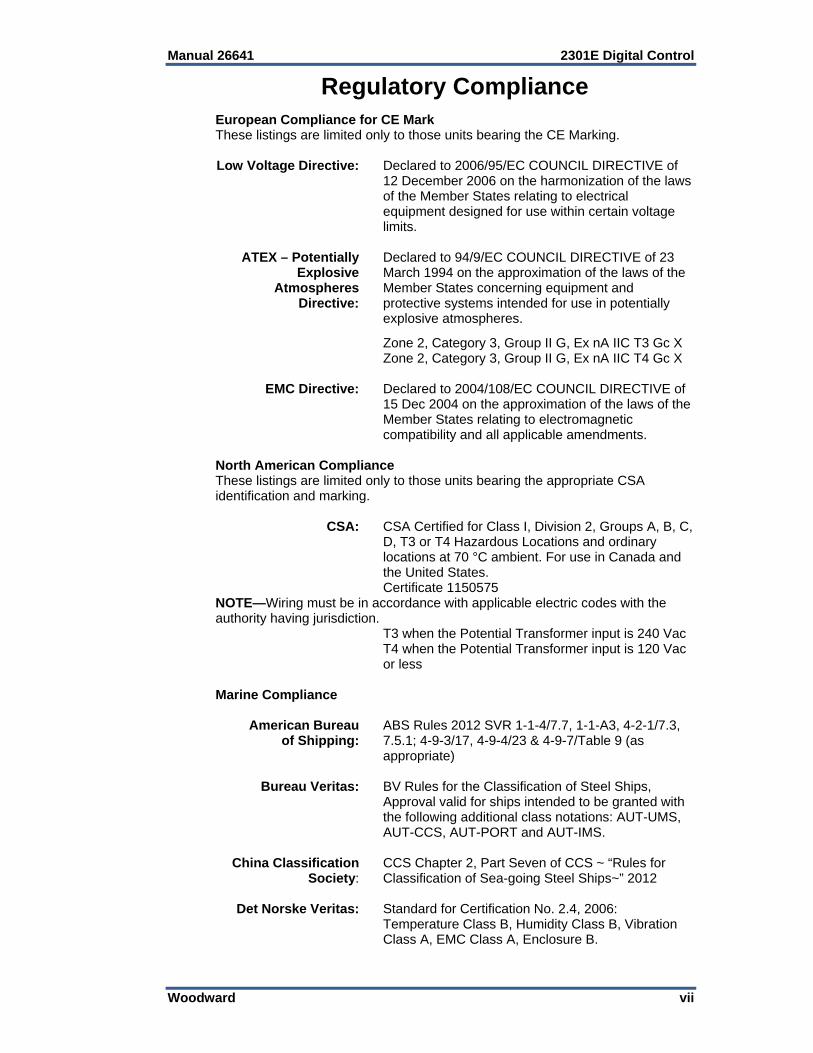
Regulatory Compliance European Compliance for CE Mark These listings are limited only to those units bearing the CE Marking. Low Voltage Directive: Declared to 2006/95/EC COUNCIL DIRECTIVE of
12 December 2006 on the harmonization of the laws of the Member States relating to electrical equipment designed for use within certain voltage limits.
ATEX – Potentially Declared to 94/9/EC COUNCIL DIRECTIVE of 23 Explosive March 1994 on the approximation of the laws of the Atmospheres Member States concerning equipment and Directive: protective systems intended for use in potentially
explosive atmospheres.
Zone 2, Category 3, Group II G, Ex nA IIC T3 Gc X Zone 2, Category 3, Group II G, Ex nA IIC T4 Gc X EMC Directive: Declared to 2004/108/EC COUNCIL DIRECTIVE of
15 Dec 2004 on the approximation of the laws of the Member States relating to electromagnetic compatibility and all applicable amendments.
North American Compliance These listings are limited only to those units bearing the appropriate CSA identification and marking. CSA: CSA Certified for Class I, Division 2, Groups A, B, C,
D, T3 or T4 Hazardous Locations and ordinary locations at 70 °C ambient. For use in Canada and the United States.
Certificate 1150575 NOTE—Wiring must be in accordance with applicable electric codes with the authority having jurisdiction. T3 when the Potential Transformer input is 240 Vac T4 when the Potential Transformer input is 120 Vac
or less Marine Compliance American Bureau ABS Rules 2012 SVR 1-1-4/7.7, 1-1-A3, 4-2-1/7.3, of Shipping: 7.5.1; 4-9-3/17, 4-9-4/23 & 4-9-7/Table 9 (as
appropriate) Bureau Veritas: BV Rules for the Classification of Steel Ships,
Approval valid for ships intended to be granted with the following additional class notations: AUT-UMS, AUT-CCS, AUT-PORT and AUT-IMS.
China Classification CCS Chapter 2, Part Seven of CCS ~ “Rules for Society: Classification of Sea-going Steel Ships~” 2012 Det Norske Veritas: Standard for Certification No. 2.4, 2006:
Temperature Class B, Humidity Class B, Vibration Class A, EMC Class A, Enclosure B.

2301E Digital Control Manual 26641
viii Woodward
Lloyd’s Register LR Type Approval Test Specification No. 1, 2002 for of Shipping: Shipping: Environmental Categories ENV1, ENV2
and ENV3 Nippon Kaiji Kyokai: Requirements specified in Chapter 1, Part 7 of
Guidance for the approval and Type Approval of materials and equipment for Marine use and relevant Society’s Rules.
Australia & New Zealand Compliance These listings are limited to those units bearing the C-Tick mark: C-Tick (ACA/RSM): Declared Separately to the Australian
Radiocommunications Act of 1992 and the New Zealand Radiocommunications Act of 1989.
Special Conditions for Safe Use: The control must be installed in a suitable enclosure. The final combination must be approved by the local authority having jurisdiction. Connect the ground terminal to earth ground. Use supply wire rated for minimum 75 °C Use signal wire rated for a minimum of 240 Vac. Per EN 60079-15:2010: Device meets ATEX Zone 2 requirements when installed in an ATEX compliant IP54 or better enclosure. T3 when the Potential Transformer input is 240 Vac. T4 when the Potential Transformer input is 120 Vac or less.
EXPLOSION HAZARD—Do not remove covers or connect/disconnect electrical connectors unless power has been switched off or the area is known to be non-hazardous.
Substitution of components may impair suitability for Class I, Division 2.
RISQUE D’EXPLOSION—Ne pas enlever les couvercles, ni raccorder / débrancher les prises électriques, sans vous en assurez auparavant que le système a bien été mis hors tension; ou que vous vous situez bien dans une zone non explosive.
La substitution de composants peut rendre ce matériel inacceptable pour les emplacements de Classe I, Division 2.
Manual 26641 2301E Digital Control
Woodward 1
Chapter 1. General Information
Description The Woodward 2301E controls load sharing and speed of generators driven by diesel or gaseous engines. (These power sources are referred to as “prime movers” throughout this manual.) The 2301E is a microprocessor-based digital control designed to include the functions of and be compatible with 2301A and 2301D load sharing controls. The increased flexibility of software allows the 2301E to include control functions that required additional equipment in previous versions of 2301A and 2301D control systems. The 2301E therefore is suitable for upgrading existing control systems for increased functionality in new installations. The 2301E has the following Woodward part numbers:
8273-1011 2301E Load Sharing and Speed Control, 24 Vdc input, Ordinary Locations
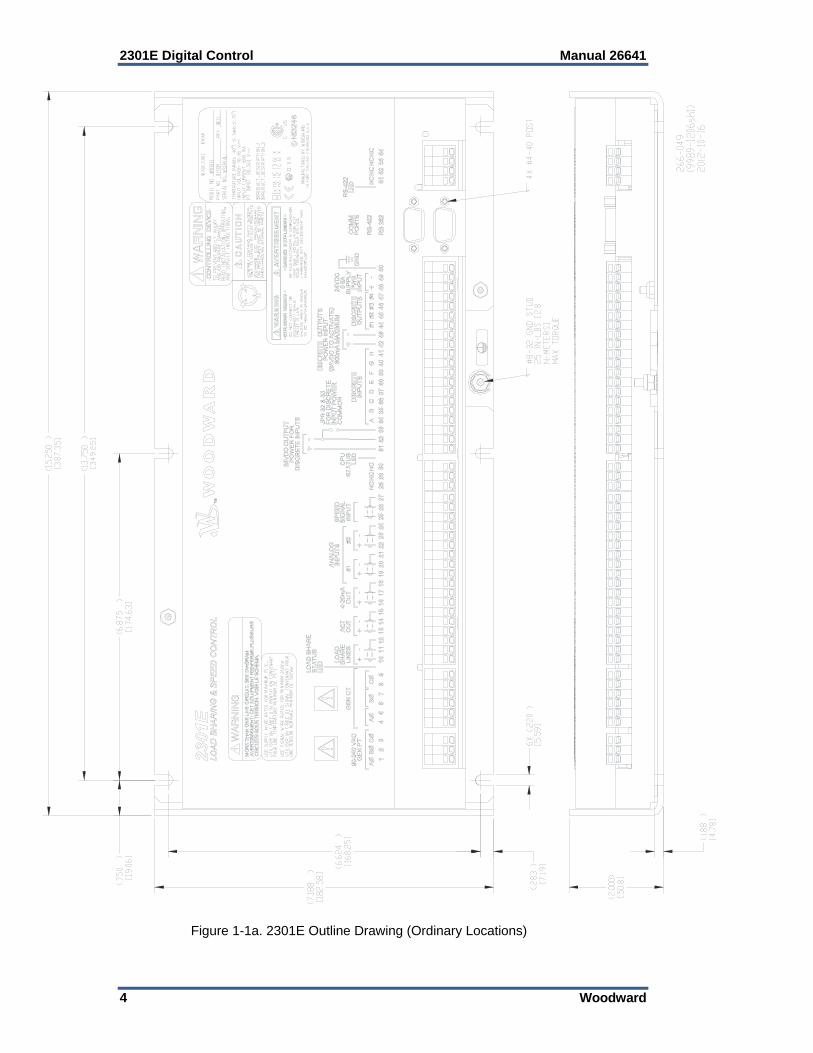
8273-1012 2301E Load Sharing and Speed Control, 24 Vdc input, Hazardous Locations
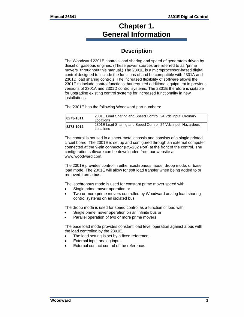
The control is housed in a sheet-metal chassis and consists of a single printed circuit board. The 2301E is set up and configured through an external computer connected at the 9-pin connector (RS-232 Port) at the front of the control. The configuration software can be downloaded from our website at www.woodward.com. The 2301E provides control in either isochronous mode, droop mode, or base load mode. The 2301E will allow for soft load transfer when being added to or removed from a bus. The isochronous mode is used for constant prime mover speed with: Single prime mover operation or Two or more prime movers controlled by Woodward analog load sharing
control systems on an isolated bus The droop mode is used for speed control as a function of load with: Single prime mover operation on an infinite bus or Parallel operation of two or more prime movers The base load mode provides constant load level operation against a bus with the load controlled by the 2301E. The load setting is set by a fixed reference, External input analog input, External contact control of the reference.

2301E Digital Control Manual 26641
2 Woodward
The 2301E Control Hardware includes: 1 Load Sensor 1 Actuator Driver 1 MPU Speed Sensor 1 Configurable Analog Output 2 Configurable Analog Inputs 8 Discrete (Switch) Inputs (3 inputs are configurable) 4 Configurable Discrete (Relay Driver) Outputs 2 Serial Ports The following is an example of the typical hardware needed for a 2301E system controlling a single prime mover and generator: A 2301E electronic control An external 18 to 36 Vdc power source A speed-sensing device, typically a Magnetic Pickup (MPU) A proportional actuator to position the fuel-metering device Current and potential transformers for measuring the load carried by the
generator The engine and generator synchronous speed (50 or 60 Hz Generator Frequency) needs to be within 90 to 3600 rpm. The frequency from the magnetic pickup must be within the range of 100 to 25 000 Hz at rated speed. The 2301E speed range needs to be configured using an external computer during installation. The 2301E has special algorithms that will enhance the speed controls transient response by utilizing Load Pulse and Load Rejection logic. By looking at the derivative or rate of change of the generator load, we can anticipate a speed or frequency change. This anticipation logic can temporarily bump the speed up or down to counter-react the speed change due to load. Service Menu W contains all of the variables to set up this feature. These 2301E controls operate with an input of 18 to 36 Vdc.
Applications Because of the configuration software available in the 2301E hardware, application variations can be selected using an external computer. Changing the application to accommodate engine speed range, gear teeth, and selection of forward or reverse acting actuator is a matter of software setup rather than changing hardware. See Chapter 4 to enter control set points.
The speed is factory set for 900 rpm, 900 Hz MPU speed with 60 teeth. Using the wrong speed configuration could cause an overspeed with resulting damage to equipment or personal injury or death.
The 2301E Control can be configured for forward- or reverse-acting applications. In reverse-acting systems, the actuator calls for more fuel when the actuator voltage decreases. Complete loss of voltage to the actuator will drive the actuator to full fuel. This allows a backup mechanical ballhead governor to take control rather than shut down the prime mover as would a direct-acting system.
External wiring connections for reverse-acting controls are identical to those for direct-acting controls.

Manual 26641 2301E Digital Control
Woodward 3
Control Options Here is a brief summary of programmable options in addition to speed range and actuator type: Actuator current range 0–20 mA, 4–20 mA, 0–200 mA, or PWM.
o Current is for the Actuator Output, PWM is on Discrete Out DO1. Speed trim with external raise and lower switches. Tunable rates. External setting of analog speed reference input or an external analog base
load reference. Multiple dynamics options— single dynamics setting selection of 2 sets of dynamics switched with Circuit Breaker Aux input 5 slope gain settings error window gain ratio Start fuel limiter / Manifold Air Pressure limiter / Torque Limiter / Idle Fuel
limiter Programmable Analog Output Programmable Discrete Outputs Programmable Discrete Inputs
References The following publications contain additional product or installation information on Load Sharing and Speed Controls, and related components. They can be ordered from any Woodward office. Manual Title 25070 Electric Governor Installation Guide 25195 Governing Fundamentals 82510 Magnetic Pickups and Proximity Switches for Electric Governors 82715 Guide for Handling and Protection of Electronic Controls, Printed
Circuit Boards, and Modules Product Spec Title 03404 2301E Digital 2301 Control 82516 EG-3P/3PC Actuator 82575 EGB-1P/2P Governor/Actuator
2301E Digital Control Manual 26641
4 Woodward
Figure 1-1a. 2301E Outline Drawing (Ordinary Locations)
Manual 26641 2301E Digital Control
Woodward 5
Figure 1-1b. 2301E Outline Drawing (Hazardous Locations)
2301E Digital Control Manual 26641
6 Woodward
A
ACTUATORB
WARNING
3
9
8
7
6
5
4
A
B
C
OPTIONAL CURRENTTRANSFORMER CONNECTION
2
AMMETERS, ETCON SWITCHBOARD 8
MPU SPEED INPUT #1(1-30 VAC)
ANALOG INPUT #2 (CONFIGURABLE)(0-5 VDC, 4-20mA, OR 2.5 VDC)
ANALOG INPUT #1 (CONFIGURABLE)( 2.5 VDC)
ANALOG OUTPUT (CONFIGURABLE)4-20mA
ACTUATOR OUTPUT0-20mA OR 0-200mA
LOAD SHARE
2
3
4
5
6
7
8
9
10
11
12
13
14
15
16
17
18
19
20
21
22
23
24
25
26
27
1
1
1
1
1
1
1
4
AMMETERS, ETCON SWITCHBOARD 8
TO VOLTMETER, ETCON SWITCHBOARD
MAINBUS
CIRCUITBREAKER
WARNING3
90-240 VAC 45-66 HZ POTENTIAL VOLTAGE
5
A
B
C
GENERATOR4
4
6
DETAIL "A"
2
2
2
28
29
30 1
MPU SPEED INPUT #2(1-30 VAC)
10
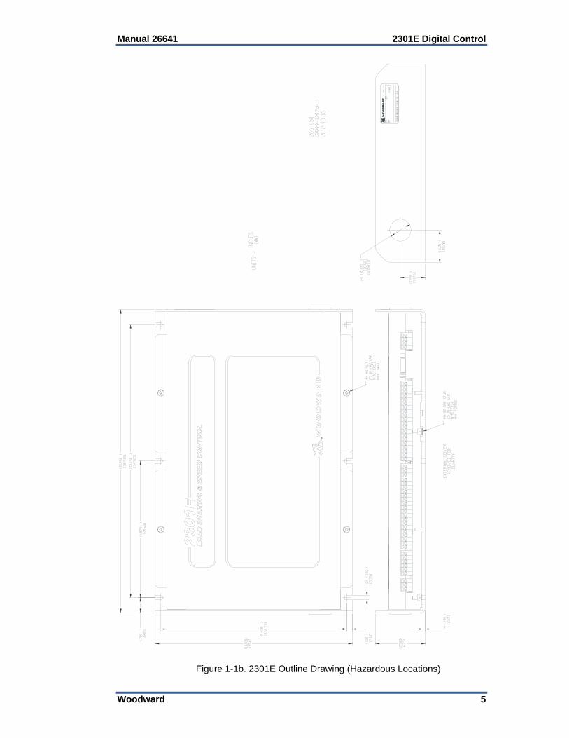
Figure 1-2a. 2301E Control Wiring Diagram (sheet 1)
Manual 26641 2301E Digital Control
Woodward 7
RT-
T-
R-
RT+
9
6
7
8
GND
R+
T+
1
2
3
4
5
RS-422 PORT
9
6
7
8
COM
TX
RX
1
2
3
4
5
RS-232 PORT
(9-DF)
SERIAL I/0
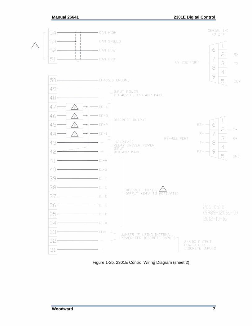
DISCRETE OUTPUT
DISCRETE INPUTS(APPLY +24V TO ACTIVATE)
7
24VDC OUTPUTPOWER FORDISCRETE INPUTS
JUMPER IF USING INTERNALPOWER FOR DISCRETE INPUTS
+12/24VDCRELAY DRIVER POWERINPUT(0.8 AMP MAX)
INPUT POWER(18-40VDC, 0.59 AMP MAX)
COM
DI-A
DI-B
DI-C
DI-D
DI-E
DI-F
DI-G
DI-H
DO-1
DO-2
DO-3
DO-4
CHASSIS GROUND
31
54
53
52
51
50
49
48
47
46
45
44
43
42
41
40
39
38
37
36
35
34
33
32
CAN GND
CAN HIGH
9
9
9
9
10
CAN LOW
CAN SHIELD
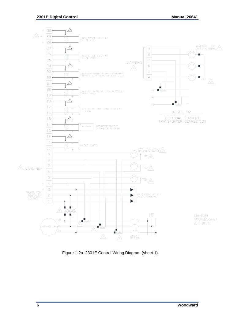
Figure 1-2b. 2301E Control Wiring Diagram (sheet 2)
2301E Digital Control Manual 26641
8 Woodward
NOT AVAILABLE ON THE 2301E10
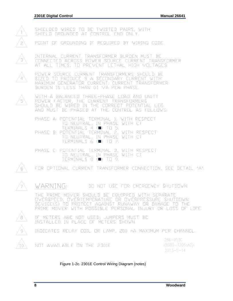
SHIELDED WIRES TO BE TWISTED PAIRS, WITH SHIELD GROUNDED AT CONTROL END ONLY.
POINT OF GROUNDING IF REQUIRED BY WIRING CODE.
INTERNAL CURRENT TRANSFORMER BURDEN MUST BE CONNECTED ACROSS POWER SOURCE CURRENT TRANSFORMER AT ALL TIMES, TO PREVENT LETHAL HIGH VOLTAGES.
POWER SOURCE CURRENT TRANSFORMERS SHOULD BE SIZED TO PRODUCE 5 A SECONDARY CURRENT WITH MAXIMUM GENERATOR CURRENT. CURRENT TRANSFORMER BURDEN IS LESS THAN 0.1 VA PER PHASE.
WITH A BALANCED THREE-PHASE LOAD AND UNITY POWER FACTOR, THE CURRENT TRANSFORMERS SHOULD BE WIRED IN THE CORRECT POTENTIAL LEG AND MUST BE PHASED AT THE CONTROL AS FOLLOWS:
PHASE A: POTENTIAL TERMINAL 1, WITH RESPECT TO NEUTRAL, IN PHASE WITH CT TERMINALS 4 ( ) TO 5. PHASE B: POTENTIAL TERMINAL 2, WITH RESPECT TO NEUTRAL, IN PHASE WITH CT TERMINALS 6 ( ) TO 7.
PHASE C: POTENTIAL TERMINAL 3, WITH RESPECT TO NEUTRAL, IN PHASE WITH CT TERMINALS 8 ( ) TO 9.
FOR OPTIONAL CURRENT TRANSFORMER CONNECTION, SEE DETAIL "A".
DO NOT USE FOR EMERGENCY SHUTDOWN.
THE PRIME MOVER SHOULD BE EQUIPPED WITH SEPARATE OVERSPEED, OVERTEMPERATURE OR OVERPRESSURE SHUTDOWN DEVICE(S) TO PROTECT AGAINST RUNAWAY OR DAMAGE TO THE PRIME MOVER WITH POSSIBLE PERSONAL INJURY OR LOSS OF LIFE.
IF METERS ARE NOT USED, JUMPERS MUST BE INSTALLED IN PLACE OF METERS SHOWN.
INDICATES RELAY COIL OR LAMP, 200 mA MAXIMUM PER CHANNEL.
WARNING:
1
2
3
4
5
6
7
8
9
Figure 1-2c. 2301E Control Wiring Diagram (notes)
Manual 26641 2301E Digital Control
Woodward 9
Chapter 2. Installation
Introduction This chapter contains general installation instructions for the 2301E control. Power requirements, environmental precautions, and location considerations are included to determine the best location for the control. Additional information includes unpacking instructions, electrical connections, and an installation check-out procedure.
Due to typical noise levels in engine and turbine environments, hearing protection should be worn when working on or around the 2301E.
The surface of this product can become hot enough or cold enough to be a hazard. Use protective gear for product handling in these circumstances. Temperature ratings are included in the specification section of this manual.
External fire protection is not provided in the scope of this product. It is the responsibility of the user to satisfy any applicable requirements for their system.
Unpacking Before handling the control, read all of this chapter and “Electrostatic Discharge Awareness” at the beginning of this manual. Be careful when unpacking the electronic control. Check the control for signs of damage such as bent or dented panels, scratches, and loose or broken parts. If any damage is found, immediately notify the shipper. Do not take the control out of the ESD bag it ships in until ESD precautions are in place. Keep yourself discharged while handing the unit outside the ESD bag, at least until it is grounded.
Power Requirements The 2301E control requires a voltage source of 18 to 36 Vdc, with a current capacity of at least 600 mA for operating power. If a battery is used for operating power, an alternator or other battery charging device is necessary to maintain a stable supply voltage. The battery charging device should be suppressed from load dump events or the power bus must have central suppression. The 2301E does not have sufficient capability to withstand all battery load dump events.
To prevent damage to the control, make sure that the alternator or other battery-charging device is turned off or disconnected before disconnecting the battery from the control.

2301E Digital Control Manual 26641
10 Woodward
Location Considerations This product is intended for installation in a “closed electrical operating area” or in an enclosed industrial control cabinet. Consider these requirements when selecting the mounting location: Adequate ventilation for cooling Space for servicing and repair Protection from direct exposure to water or to a condensation-prone
environment Protection from high-voltage or high-current devices, or devices which
produce electromagnetic interference (segregate the unit and wiring by at least 15 cm (6 inches).
Avoidance of vibration Selection of a location that will provide an operating ambient air temperature
range of –40 to +70 °C (–40 to +158 °F) at the control The control must NOT be mounted on the engine.
Electrical Connections All inputs and outputs are made through screwless spring-actuated terminal blocks. Use ESD precautions noted above when installing the wiring to prevent damage due to ESD. The spring clamp can be actuated by using a standard 2.5 mm or 3/32 inch flat bladed screwdriver. The terminal blocks accept wires from 0.08–4 mm² (27–12 AWG). Two 18 AWG or three 20 AWG wires can be easily installed in each terminal. Wires for the fixed mounted power terminals should be stripped 5–6 mm (0.22 inch) long.
Do not tin (solder) the wires that terminate at the terminal blocks. The spring-loaded terminal blocks are designed to flatten stranded wire, and if those strands are tinned together, the connection loses surface area and is degraded.
Due to the hazardous location listings associated with this product, proper wire type and wiring practices are critical to operation.
Do not connect any cable grounds to “instrument ground”, “control ground”, or any non-earth ground system. Make all required electrical connections based on the wiring diagrams (Figures 1-2a/b/c).
Cabling and installation wiring can affect the Electromagnetic Compatibility (EMC) of the device, its ability to operate in an environment without being interfered with, or interfering with other devices. Often other controls are installed in the same enclosure, too. To address EMC concerns, it is recommended that all low-current wires be separated from all high-current wire and similarly for high-voltage and low-voltage wiring. For example, relay contact wiring and electric motor drive or ignition system wiring should be at least 30 cm (12 inches) from any 2301E wiring. And for example, analog inputs/output wiring should be separated from power wiring by at least 15 cm (6 inches).

Manual 26641 2301E Digital Control
Woodward 11
Shields and Grounding An individual shield termination is provided at the terminal block for each of the signals requiring shielding. All of the inputs having a shield pin should be wired using shielded, twisted-pair wiring. The optimum exposed wire length beyond the shield should be limited to 25 mm (1 inch); however, up to 75 mm (3 inches) may be used. Relay outputs, contact inputs, and power supply wiring do not normally require shielding, but can be shielded if desired. Shields should terminate to chassis and may be direct or share a shield pin except the AI or CAN shields. The 2301E is designed for shield termination to earth ground at the control. If intervening terminal blocks are used in routing a signal, the shield should be continued through the terminal block. If shield grounding is desired at the terminal block, it should be ac coupled to earth with a capacitor. All other shield terminations except at the control (in the field) should be ac coupled to earth through a capacitor. A 1000 pF, 500 V capacitor is typically sufficient, however 1–10 nF, 500–1500 V may be used or needed, and 1000 pF (1 nF) 1000 V is recommended. The intent is to provide a low impedance path to earth for the shield at frequencies of 150 kHz and up. Multiple direct connections of a shield to earth risk high levels of current to flow within the shield (exception, see note below on cabinet installations). Shields can be grounded at both ends (2301E and load) if the cable length is sufficiently short (i.e., within a cabinet, less than about 10 m straight line between the ground points) to prevent ground loop current in the shield.
Cabinet Installations: If the 2301E is installed in a cabinet, shielded I/O can be terminated directly to the cabinet (earth ground) at the entry/exit of the cabinet, as well as at the control (recommended). Installation concerns associated with wiring in systems with other devices are addressed in the electrical connections section.
Figure 2-1. Installation of Wiring into Terminal
LED System Status Indicators The LED located between terminals 30 and 31 is a two colored LED. The following provides the functions of the LED status: LED Off = Power Off LED Green = System On LED Solid Red = I/O Lock LED Flashing Red = Fault (This indicates a major problem and should be
returned to Woodward for service).
2301E Digital Control Manual 26641
12 Woodward
Setting Speed Range The Microprocessor inside the 2301E calculates the speed range to be used by entering the engine/generator synchronous speed and number of gear teeth. This configured speed sets the hardware-to-software scaling. The rated speed setting is set in service as the speed reference selected when the Rated switch is closed.
The number of gear teeth is used by the control to convert pulses from the speed sensing device to engine rpm. To prevent possible serious injury from an overspeeding engine, make sure the control is properly programmed to convert the gear-tooth count into engine rpm. Improper conversion could cause engine overspeed.
The speed range is factory set for 900 Hz, 900 rpm (60 teeth). Refer to Chapter 4 to change speed range and prevent possible overspeed. Using the wrong speed range could cause an overspeed with resulting damage to equipment or personal injury or death.
Potential Transformer Connections (Terminals 1–3) Connect the potential transformer secondary leads to the following terminals: Phase A to terminal 1 Phase B to terminal 2 Phase C to terminal 3 The potential transformer secondary line-to-line voltage must produce 90 to 120 Vac or 200 to 240 Vac. The PT and CT input connections are not needed if using a DSLC for load sharing or load control. Refer to the plant wiring diagram, Figure 1-2.
Current Transformer Connections (Terminals 4–9) The standard method of connecting the current transformers is shown in the plant wiring diagram, Figure 1-2. An alternate method is the open delta connection shown in the insert in the plant wiring diagram.
Real Power Load Calculation The control uses the equation Power = 3 * V * I * P.F. where V = Voltage, I = current, and P.F. = Power Factor. In the 2301E, the PT Voltage part of the equation is deemed to be constant. Therefore if the Voltage on the system changes, the calculated Power will change a small amount.
Load Share Lines (Terminals 10–12) The Load Share Lines provide an analog communication path between compatible controls. The 2301E provides an internal relay for connecting the Load Share Signal to the internal circuitry at the appropriate times. When the internal relay is closed, a green LED will illuminate between terminals 9 and 10. Because the load-sharing-line relay is contained in the control, no relay is required between the control and the load-sharing-line bus.

Manual 26641 2301E Digital Control
Woodward 13
Do not touch Load Share pins without discharging ESD to physical earth first and making sure the control’s PE terminal is connected to physical earth before wiring. The load share signals have 4 kV ESD withstand when the control is not grounded rather than 8 kV or more on other pins. (Load Share Lines have at least 7 kV withstand when the control is grounded.) Greater than 4 kV ESD events are uncommon in the typical installation environment, but may happen.
Use shielded cable and connect the load-sharing lines directly to terminals 10(+) and 11(–). Connect the shield to terminal 12(chassis). When all controls in the system are of the 2301E, 2301D or 2301A types, the shields may be connected continuously between controls. When load sharing with different controls, do not connect the shields at the point where connections are made to the load-sharing-line bus or if needed, connect only through a capacitor. The droop contact for selecting droop or isochronous operation is wired in series with the circuit-breaker auxiliary contact between terminal 37 (configurable) and terminal 31 (see CB Aux/Droop contact). When running a single unit on an infinite bus with an external load control device, terminals 37 (configurable) and 40 must be connected to terminal 31 to connect the Load Matching Circuit to the load-sharing lines. The load-sharing lines must be wired to the external load control device. The circuit-breaker auxiliary contact will then be connected to this device and not to the 2301E.
Power Supply (Terminals 48–50) Run the power leads directly from the power source to the control, connecting the negative lead to terminal 49, and the positive lead to terminal 48. Pin 50 is provided as an optional Physical Earth (PE) wire landing point in addition to the PE Ground stud, in case the particular installation requires a PE wire to be run with dc power. Either both grounds must be connected or just the PE stud connected to the cabinet/chassis, as Physical Earth though a 30 cm long by 13 mm wide (12 inches long, ½ inch wide) or shorter flat hollow braid or comparable surface area wire, the ratio of copper surface to length may be used to provide shorter smaller grounding wires. When power is applied, the 2301E begins performing internal memory tests to ‘boot-up’ the processor, which takes approximately 2 seconds to complete. The CPU Status LED between terminals 30 and 31 remains on during this boot-up. The control will remain in I/O lock and will not control the prime mover until the boot-up is complete. For systems requiring fast start functions, it will be necessary to continuously power the 2301E.
DO NOT attempt to start the prime mover while the CPU Status LED is RED.
DO NOT apply power to the control at this time. Applying power before a control is completely connected may damage the control.
2301E Digital Control Manual 26641
14 Woodward
The 18–36 Vdc input power must be supplied from a power supply/battery charger certified to IEC standard with SELV (Safety Extra Low Voltage) classified output. The installer should properly size wiring and fusing for the input power and PT/CT circuits.
Discrete Inputs (Terminals 34–41) Discrete inputs are the switch or contact input commands to the 2301E control. They interact in such a way as to allow engine control and power management under a variety of conditions. The user has the capability to change the logic of the discrete inputs through the software interface. For example the user can now change the logic of the Run / Stop discrete input from Close to Run and Open to Stop to Close to Stop and Open to Run. All of the discrete inputs have this capability. (Note double pole configuration below for critical I/O going between points physically > 30 m in length apart.) The following example is using the default logic for the discrete inputs. Positive Voltage is supplied to the discrete input terminal when an input switch or relay contact closes. This will cause the input state for that discrete input to be “TRUE” (displayed as “CLOSED”). The input terminal will be open circuited when the input switch or relay contact opens. This will cause the input state for that discrete input to be “FALSE” (displayed as “OPEN”). When the input switch or relay contact is closed, the voltage supplying the discrete inputs should be present from the appropriate discrete input (terminal 34, 35, 36, 37, 38, 39, 40, or 41) to terminal 33 (common). Terminal 33 is the common return path for all of the discrete input channels. A lower voltage indicates that the switch contacts have too high a resistance when closed and should be replaced. These terminals must be isolated from ground. In systems that provide an external low voltage source to power the 2301E control, the discrete inputs may be powered by this external low voltage. The voltage source used must be capable of supplying 100 mA at a voltage level of 18 to 36 Vdc. Connect the external low voltage source negative to terminal 33(–). Connect the external low voltage source positive to the appropriate input switch or relay contact and connect the mated switch or relay contact to the corresponding discrete input terminal on the 2301E control. In systems where the external low voltage dc power is not appropriate, the discrete inputs may be powered by the internal 24 Vdc Discrete Input Power source at terminal 31 and 32. This source is capable of supplying 100 mA at a voltage level of 24 Vdc. Connect the internal 24 Vdc voltage source positive from terminal 31 to the appropriate input switch or relay contact, and connect the mated switch or relay contact to the corresponding discrete input terminal on the 2301E control. Assure that a connection exists between terminal 32 and terminal 33 when using the internal Discrete Input Power. Do not power other devices with the internal discrete input power source, and assure that the switch or relay contacts used are isolated from any other circuit or system. The internally provided contact wetting voltage may not be used for anything other than DI Contact wetting; it is dedicated to this function.
Discrete inputs with cable lengths where the end points are physically greater than 30 meters apart and which are used for critical functions, such as emergency stop, should not be floated in either an on or off state. These inputs should be switched to either +24 Vdc or ground, never floated or tied to reference with a resistor.

Manual 26641 2301E Digital Control
Woodward 15
The discrete inputs are capable through software programming to change the logic or state of the input. Please verify the state of your input before starting the engine.
Close to Run or Minimum Fuel (Terminal 34) (Discrete Input A)
The external contact used to activate the Close to Run command connects to terminal 34. This discrete input changes the control operation by immediately decreasing the fuel demand to zero. When the switch or relay contacts are closed, the control is allowed to control the fuel in an attempt to control the speed/load of the prime mover. When the switch or relay contacts are open, the Minimum Fuel Function will immediately pull the fuel demand to zero.
Do NOT use the minimum fuel contact as part of any emergency stop sequence.
Discrete Inputs B, C, D (Terminals 35, 36, 37) Discrete Inputs B, C and D (terminals 35, 36, and 37) are configurable for the following functions: Not used Failed speed override Reset Select 2nd dynamics Shutdown external Idle/rated switch Generator Breaker (52G) Isoch / Droop Derate KW Load Reference 50/60 Hertz Operation The Factory default settings are as follows: Discrete input B (terminal 35) is configured for 2 Reset. Discrete input C (terminal 36) is configured for 6 Idle/Rated switch. Discrete input D (terminal 37) is configured for 7 Generator Breaker
droop/Isochronous. If none of functions are used, the Discrete Input should be set to Not Used.
2301E Digital Control Manual 26641
16 Woodward
Failed Speed Override A contact to override the failed speed signal circuit can be installed in series with the discrete input configured for the Failed Speed Override and the dc power to the discrete inputs. When the contact is open, the control operates normally, turning the control output off in the event of a loss of speed signal. Closing the contact overrides the failed speed signal circuit as may be required for start-up. Prior to start-up of the prime mover, the speed signal is non-existent. On prime movers with cranking motors, the cranking speed is usually sufficient to provide a speed signal, so an override contact is not needed for starting. On some systems, the Failed Speed Signal Override contact must be closed in order to allow the actuator to open and provide fuel for starting. If a failed speed signal override contact is used, it should be of the momentary type to ensure that the failed speed sensor shutdown circuit is enabled after start-up. The logic function of this input can be modified to be normally open or normally closed.
Reset One of the three configurable discrete contacts can be configured as a reset. The reset can be used to reset alarms or shutdowns. The reset is the same as the “software reset” Reset shutdown in the Service menu C**SHUTDOWNS** or Reset alarms in menu D**ALARMS**. An automatic reset is given to clear any alarm or shutdown when the engine clears the MPU Failsafe speed, typically 5% of rated speed. If the alarm or shutdown still exists, the engine will shut down again. After a shutdown has occurred (for example an overspeed or an MPU failure) you can only reset the control when the engine speed is zero. The logic function of this input can be modified to be normally open or normally closed.
Select 2nd Dynamics One of the three configurable discrete contacts can be configured as Select 2nd dynamics. In menu I**DYNAMICS #2** the parameter enable dynamics 2 w/CB should be configured at TRUE to enable the 2nd dynamics. This contact can be connected to a clutch-feedback or when a different operating mode of the engine is used to activate the 2nd dynamics, when a separate set of PID settings are necessary. The logic function of this input can be modified to be normally open or normally closed.
Shutdown External One of the three configurable discrete contacts can be configured as External shutdown. When the contact is open, the control operates normally, Closing the contact will STOP the engine. This contact can be used as a Emergency shutdown. When the contact is opened again a reset should be given before the engine can be started again. The reset can be given by a reset input if configured, or the Run/Stop Fuel contact 34 should be toggled. The logic function of this input can be modified to be normally open or normally closed.
Manual 26641 2301E Digital Control
Woodward 17
Idle / Rated Speed The external contact used to activate the Rated Speed command connects to terminal 36 (default). This discrete input changes the control operation by increasing the speed reference to RATED SPEED and decreasing the speed reference to IDLE SPEED. When the switch or relay contacts are closed, the speed reference will ramp for a time set by the Accel Time to the rated speed control point. When the switch or relay contacts are open, the speed reference will ramp for a time set by the Decel Time to the idle speed control point. The Idle Speed function is disabled by internal logic when the generator breaker is closed. The Rated Speed input should be left closed when the generator breaker is closed. If the application does not require an idle speed setting, the Rated Speed input can be left closed at all times. This can be done by connecting it directly to the positive Discrete Input Power source. The logic function of this input can be modified to be normally open or normally closed.
Idle/Rated Software Switch An optional automatic Idle to Rated switch is also available. When the engine is started it will control at the idle speed setpoint, after a tunable delay time the speed reference will ramp to the rated speed setpoint. This switch is enabled in Configure menu A**Speed Control Functions** parameter 11 ENABLE AUTO IDLE/RATED (set to TRUE). In Service menu G**Speed Setting** parameter 12 DELAY TIME IDLE TO RATED can be adjusted to set the delay time before rated is selected.
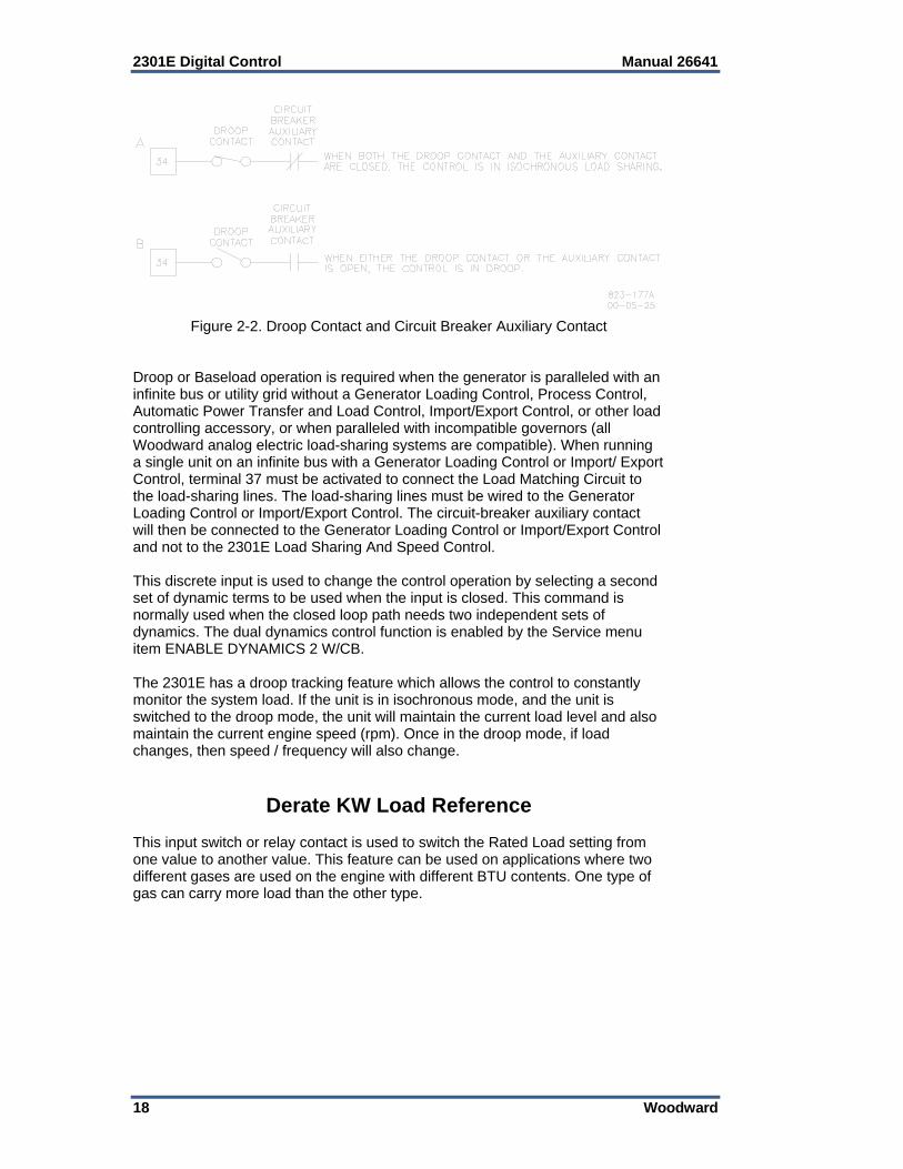
CB Aux/Droop Contact The input switch or relay contact used to activate the Load Control connects to terminal 37 (default). This discrete input is used to switch the control into isochronous mode, which allows the Load Control Function to operate. It is typically connected to an auxiliary contact on the generator circuit breaker. When the breaker closes, the input switch or relay contact should also close. When the external switch or relay contacts are open, the control will operate in Droop Mode. A switch in series with the auxiliary contact on the generator circuit breaker will allow manually selecting Droop Mode or Base Load/Isochronous Mode. Open this switch for Droop Mode. Close this switch for Base Load/Isochronous Modes. When both the droop contact and circuit-breaker auxiliary contact are closed, the control is in the isochronous load-sharing mode (Figure 2-2). In this mode the internal load-sharing-line relay is energized, the droop signal is disabled permitting isochronous load sharing, and the load-matching circuit is connected to the load-sharing lines. The Generator Load contact at terminal 40 must be closed for isochronous load sharing, otherwise the generator load will be controlled at the unload trip level, and the internal relay will not energize to allow load sharing. The logic function of this input can be modified to be normally open or normally closed.
The control is in the droop mode whenever the circuit-breaker auxiliary contact is open. If a single prime mover is required to run isochronously with an isolated load, enter Load Droop Percent = 0.0 when making *LOAD SETTING * adjustments.
2301E Digital Control Manual 26641
18 Woodward
Figure 2-2. Droop Contact and Circuit Breaker Auxiliary Contact
Droop or Baseload operation is required when the generator is paralleled with an infinite bus or utility grid without a Generator Loading Control, Process Control, Automatic Power Transfer and Load Control, Import/Export Control, or other load controlling accessory, or when paralleled with incompatible governors (all Woodward analog electric load-sharing systems are compatible). When running a single unit on an infinite bus with a Generator Loading Control or Import/ Export Control, terminal 37 must be activated to connect the Load Matching Circuit to the load-sharing lines. The load-sharing lines must be wired to the Generator Loading Control or Import/Export Control. The circuit-breaker auxiliary contact will then be connected to the Generator Loading Control or Import/Export Control and not to the 2301E Load Sharing And Speed Control. This discrete input is used to change the control operation by selecting a second set of dynamic terms to be used when the input is closed. This command is normally used when the closed loop path needs two independent sets of dynamics. The dual dynamics control function is enabled by the Service menu item ENABLE DYNAMICS 2 W/CB. The 2301E has a droop tracking feature which allows the control to constantly monitor the system load. If the unit is in isochronous mode, and the unit is switched to the droop mode, the unit will maintain the current load level and also maintain the current engine speed (rpm). Once in the droop mode, if load changes, then speed / frequency will also change.
Derate KW Load Reference This input switch or relay contact is used to switch the Rated Load setting from one value to another value. This feature can be used on applications where two different gases are used on the engine with different BTU contents. One type of gas can carry more load than the other type.
Manual 26641 2301E Digital Control
Woodward 19
Raise Speed/Load Contact (Terminal 38) (Discrete Input E)
The input switch or relay contact used to activate the Raise Speed/Load command connects to terminal 38 (Discrete Input E). This discrete input changes the control operation by increasing the speed reference ramp when the CB Aux input is open, and by increasing the base load reference when in base load mode. The speed reference ramp can increase only to a software adjusted RAISE SPEED limit. The base load reference ramp can increase only to a software adjusted BASE LOAD MAXIMUM limit. Both ramps increase at software adjusted rates. De-selecting the Rated Speed command (described above) takes command control away from the Raise Speed/Load input and effectively disables the command. With the contacts open (discrete input in the “FALSE” state), the control will stop raising the speed or base load reference. Maintained simultaneous closure of this Raise Speed/Load contact along with the Lower Speed/Load contact enables the Remote Reference Input. The logic function of this input can be modified to be normally open or normally closed.
Lower Speed/Load Contact (Terminal 39) (Discrete Input F)
The input switch or relay contact used to activate the Lower Speed/Load command connects to terminal 39 (Discrete Input F). This discrete input changes the control operation by decreasing the speed reference ramp when the CB Aux input is open, and by decreasing the base load reference when in base load mode. The speed reference ramp can decrease only to a software adjusted LOWER SPEED limit. The base load reference ramp can decrease only to a software adjusted BASE LOAD MINIMUM limit. Both ramps decrease at a software adjusted rate. De-selecting the Rated Speed command (described above) takes command control away from Lower Speed/Load input and effectively disables the command. With the contacts open (discrete input in the “FALSE” state), the control will stop lowering the speed or base load reference. Maintained simultaneous closure of this Lower Speed/Load contact along with the Raise Speed/Load contact enables the Remote Reference Input. The logic function of this input can be modified to be normally open or normally closed.
Remote Speed Setting (Both Raise and Lower Contacts; Terminals 38 and 39)
(Discrete Inputs E & F) Close both the Raise Speed/Load discrete input (terminal 38) and the Lower Speed/Load (terminal 39) to put the control into the remote speed setting input mode. Analog input number one or number two must be set to *2, Remote Speed Set Point. When the control is in remote droop or isochronous mode the Remote Speed setpoint moves the Speed Ramp to the same value as the Remote Speed setpoint. Other permissives for Remote Speed Reference are: Rated Speed = TRUE, Engine Running = TRUE, and NOT in Baseload mode.

2301E Digital Control Manual 26641
20 Woodward
Load Generator (Terminal 40) (Discrete Input G)
The input switch or relay contact used to activate the Load Generator command connects to terminal 40. This discrete input will cause the Load Control Function to ramp to a distinct mode of operation. If the state of the input is “TRUE”, the Load Control Function will increase or decrease in order to achieve either Isochronous Load Sharing or Base Load operation. If the state of the input is “FALSE” (input switch or relay contact open), the Load Control Function will increase or decrease in order to achieve the Unload trip level. The CB Aux/Droop Contact discrete input must be “TRUE” for the Load Generator input to affect the control. Note: When using the 2301E in a single engine, emergency standby application, this input must be “True”. The logic function of this input can be modified to be normally open or normally closed.
Base Load (Terminal 41) (Discrete Input H)
The input switch or relay contact used to activate the Base Load command connects to terminal 41. This discrete input will cause the Load Control Function to operate in Base Load. In this mode of operation the governor will control the load on the generator. The utility (main) bus or an isochronous generator set must control the bus frequency while in Base Load operation. With the state of this input “TRUE”, isochronous load sharing with other units is disabled. With the state of this contact “FALSE”, isochronous load sharing with other units can occur. The CB Aux/Droop Contact discrete input must be “TRUE” for the Base Load input to affect the control. The logic function of this input can be modified to be normally open or normally closed.
Actuator Output (Terminals 13–15) The actuator wires connect to terminals 13(+) and 14(–). Use shielded wires with the shield connected to terminal 15 (chassis). Do not connect the shield to the actuator or any other point. The shield must have continuity the entire distance to the actuator, and must be insulated from all other conducting surfaces. Refer to the manuals listed in the “References” table for additional information on actuator installation. The current range to the actuator output is configured in software for a 0–200 mA, 4-20 mA, 0–20 mA or Pulse Width Modulation (PWM) type of actuators. When the Actuator selection is set to PWM, the output is physically switched to Discrete Output #1 on terminal 44 (See the Relay Driver Output section for wiring details). The software configuration also allows for selection of Forward or Reverse acting actuator.
Analog Inputs (Terminals 19–24) Both Analog Inputs can be configured for several different functions depending on the application needs. No connection is required to this input if this function is not needed by the application, set the function to 1 (not used).
Manual 26641 2301E Digital Control
Woodward 21
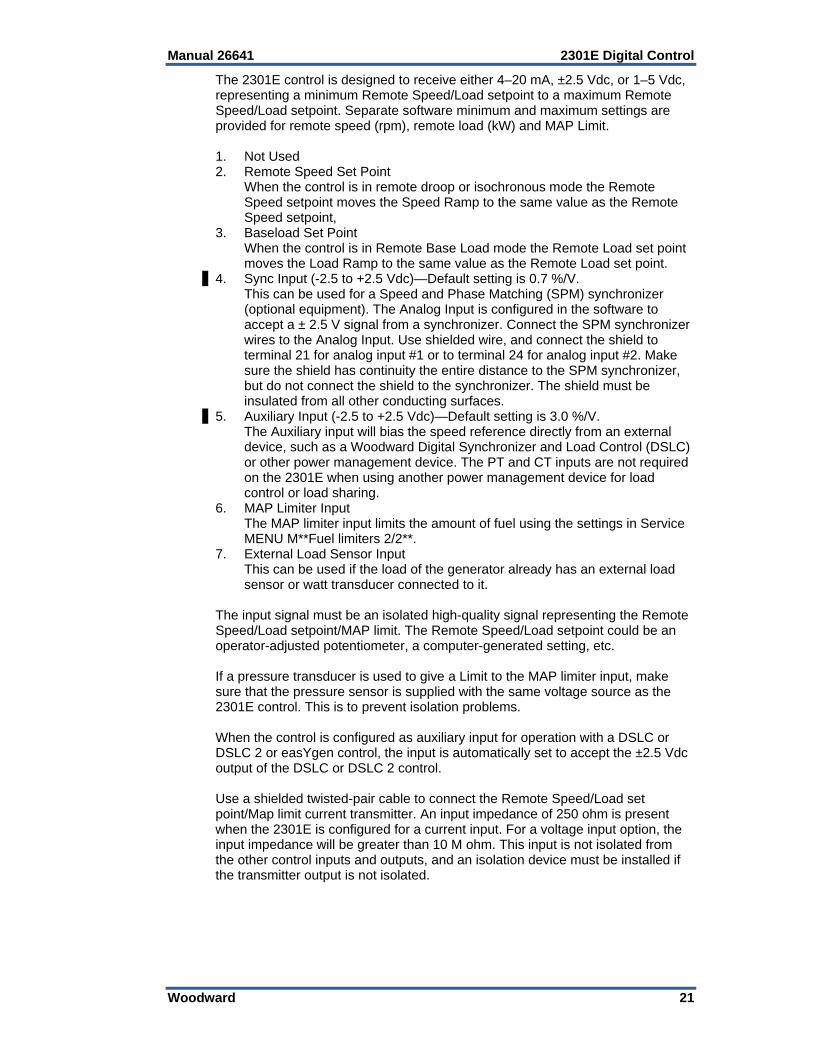
The 2301E control is designed to receive either 4–20 mA, ±2.5 Vdc, or 1–5 Vdc, representing a minimum Remote Speed/Load setpoint to a maximum Remote Speed/Load setpoint. Separate software minimum and maximum settings are provided for remote speed (rpm), remote load (kW) and MAP Limit. 1. Not Used 2. Remote Speed Set Point When the control is in remote droop or isochronous mode the Remote
Speed setpoint moves the Speed Ramp to the same value as the Remote Speed setpoint,
3. Baseload Set Point When the control is in Remote Base Load mode the Remote Load set point
moves the Load Ramp to the same value as the Remote Load set point. 4. Sync Input (-2.5 to +2.5 Vdc)—Default setting is 0.7 %/V. This can be used for a Speed and Phase Matching (SPM) synchronizer
(optional equipment). The Analog Input is configured in the software to accept a ± 2.5 V signal from a synchronizer. Connect the SPM synchronizer wires to the Analog Input. Use shielded wire, and connect the shield to terminal 21 for analog input #1 or to terminal 24 for analog input #2. Make sure the shield has continuity the entire distance to the SPM synchronizer, but do not connect the shield to the synchronizer. The shield must be insulated from all other conducting surfaces.
5. Auxiliary Input (-2.5 to +2.5 Vdc)—Default setting is 3.0 %/V. The Auxiliary input will bias the speed reference directly from an external
device, such as a Woodward Digital Synchronizer and Load Control (DSLC) or other power management device. The PT and CT inputs are not required on the 2301E when using another power management device for load control or load sharing.
6. MAP Limiter Input The MAP limiter input limits the amount of fuel using the settings in Service
MENU M**Fuel limiters 2/2**. 7. External Load Sensor Input This can be used if the load of the generator already has an external load
sensor or watt transducer connected to it. The input signal must be an isolated high-quality signal representing the Remote Speed/Load setpoint/MAP limit. The Remote Speed/Load setpoint could be an operator-adjusted potentiometer, a computer-generated setting, etc. If a pressure transducer is used to give a Limit to the MAP limiter input, make sure that the pressure sensor is supplied with the same voltage source as the 2301E control. This is to prevent isolation problems. When the control is configured as auxiliary input for operation with a DSLC or DSLC 2 or easYgen control, the input is automatically set to accept the ±2.5 Vdc output of the DSLC or DSLC 2 control. Use a shielded twisted-pair cable to connect the Remote Speed/Load set point/Map limit current transmitter. An input impedance of 250 ohm is present when the 2301E is configured for a current input. For a voltage input option, the input impedance will be greater than 10 M ohm. This input is not isolated from the other control inputs and outputs, and an isolation device must be installed if the transmitter output is not isolated.

2301E Digital Control Manual 26641
22 Woodward
Analog Input #1 (Terminals 19-20) The function for this input is default for #4, Sync Input with the hardware type fixed at ±2.5 Vdc. Selects the function for the analog input: 1 = NOT USED 2 = REMOTE SPEED SETPOINT 3 = BASELOAD SETPOINT 4 = SYNC INPUT (default) 5 = AUXILIARY SPEED SETPOINT 6 = MANIFOLD AIR PRESSURE LIMITER INPUT 7 = EXTERNAL LOAD SENSOR Sets what type of input will be used: 1 = 4–20 mA 2 = 1–5 Volt 3 = ±2.5 Volt If Analog Input #1 is used, wire with a shielded cable and connect the appropriate analog lines directly to terminals 19 (+) and 20 (–). Connect the shield to terminal 21 (chassis).
Do NOT configure Analog Inputs #1 and #2 for the same function.
Analog Input #2 (Terminals 22-23) The function of this input is default for #3, Baseload Setpoint with the hardware type set for 4–20 mA. Selects the function for the analog input: 1 = NOT USED 2 = REMOTE SPEED SETPOINT 3 = BASELOAD SETPOINT (default) 4 = SYNC INPUT 5 = AUXILIARY SPEED SETPOINT 6 = MANIFOLD AIR PRESSURE LIMITER INPUT 7 = EXTERNAL LOAD SENSOR Sets what type of input will be used: 1 = 4–20 mA 2 = 1–5 Volt 3 = ±2.5 Volt If Analog Input #2 is used, wire with a shielded cable and connect the appropriate analog lines directly to terminals 22 (+) and 23 (–). Connect the shield to terminal 24 (chassis).
Do NOT configure the Analog Inputs #1 and #2 for the same function.
Manual 26641 2301E Digital Control
Woodward 23
Speed Sensor (Terminals 25-26) Connect a speed-sensing device, such as a magnetic pickup, to terminals 25 and 26 using shielded wire. Connect the shield to terminal 27 (chassis), making sure the shield has continuity the entire distance to the speed sensor, and that the shield is insulated from all other conducting surfaces. This input is limited to a frequency range of 100–24 950 Hz and a voltage range of 1.7–35 Vac. (The MPU voltage at the 2301E must be above 2.7 Vac in case of a signal above 13 000 Hz.) With proper MPU, gear size and MPU-to-gear clearance, speed measurement should be capable down to 100 Hz. Check the speed sensor for visible damage. Standard MPU clearance is recommended to be between 0.25 and 1.0 mm (0.010 and 0.040 inch) at the closest point. Make sure that the gear has less than 0.5 mm (0.020 inch) diametric run out. See manual 82510, Magnetic Pickups and Proximity Switches for Electronic Governors.
Relay Driver Outputs (Terminals 42, 43, & 44–48) The 2301E contains four discrete output driver channels. The discrete outputs are low-side drivers with a maximum output current of 200 mA. The discrete output drivers are not isolated from each other, and are powered by an external +12 Vdc or +24 Vdc source connected at terminals 42(+) and 43(–). The Relay Driver Output pins are: #1(44), #2(43), #3(46), and #4(47). The relay driver section is isolated from the internal power supplies of the 2301E control, but all drivers share a single common. The outputs can be configured for the next parameters: Relay driver #1 can be used as a PWM actuator driver or a relay driver
depending on the selection of the Actuator Output in the Configure menu. o When configured as a PWM, power wiring configuration is dictated.
Shutdown indication—The discrete output will activate when a Shutdown is sensed.
Alarm—The discrete output will activate when an Alarm is sensed. Elec overspeed trip test—The discrete output will activate if the engine
speed exceeds the overspeed setpoint. The discrete output will de-activate when the engine speed drops below the overspeed setpoint.
Start fuel limiter in control —The discrete output will activate if the Start Fuel limiter is in control of the fuel demand. The discrete output will de-activate when something else is in control of the fuel demand.
Speed PID in control—The discrete output will activate when Speed is in control of the fuel demand. The discrete output will de-activate when something else is in control of the fuel demand.
Circuit Breaker open—The discrete output will toggle True then False for the Breaker Open Time, when the load falls below the Unload Trip level, or if the load is at minimum for 5 seconds.
Overload contact—The discrete output is only active if a Manifold Air Pressure (MAP) input is used. The discrete output will activate if the fuel demand reaches maximum.
Level switch—If one of the discrete outputs is selected for a level switch then one of the following can be set up to act as a switch, with on and off values: Speed, Speed setpoint, Start limiter, Fuel Demand, Generator Load.
CPU Failure—If the control fails, this selection will de-activate a discrete output.
In Remote Speed Control—If the control is enabled for Remote Speed control function, this discrete output will activate.

2301E Digital Control Manual 26641
24 Woodward
Power wiring for using the PWM output function is required to be local and dedicated, only located on the engine skid or relatively close to the control and PWM load. The power connected to control 48(+) and 49(–) terminals must also be used for the relay driver external Vdc source connected at terminals 42(+) and 43(–). In addition, the PWM load device power must also be from the same source as the power connected to control terminals 48(+) and 49(–-).
The PWM functionality is limited to use on skid applications. When PWM drivers are used, the 2301E must be located on the same power bus as the driven circuitry. The 2301E and the device being driven need to be co-located on the same engine. In addition, the Power bus input for the 2301E must be used to power the DO signals.
4–20 mA Output (Terminals 16–17) The analog output can be configured several different ways depending on the application needs. The output current is 4 to 20 mA. This current signal is supplied via shielded wires to terminals 16(+) and 17(–). The shield is connected to terminal 18 (chassis). Note that these terminals must be isolated from ground. The Output can be software configured to one of several control parameters. These parameters include: Engine Speed Engine Speed Reference Fuel Demand Generator Output System Load Percent Synchronizer Input Analog Input #2 Speed Setting Bias Signal Base Load Reference Misfire RPM per Sec2 The Analog Output is factory set for 4 to 20 mA, representing the engine speed. Default range is 0 to 100%. Software settings must be changed if an output of 0 to 20 mA is needed. Use shielded twisted-pair wires. For electrically isolated devices such as 4 to 20 mA analog meters, the shield should be grounded at the control end of the cable. For input to other devices, use the recommendation of the device manufacturer.
Communication Ports The control’s two serial communication ports are used to configure and service the unit. These ports are on a common return and are isolated ports. The RS-232 serial communication service port communicates using either the 2301E Toolkit Service Tool or the Control Assistant software. Refer to Figure 2-3 for plant wiring information. The RS-422 serial communication port communicates using a Modbus RTU protocol, functioning as a Modbus Slave device, via a RS-422 driver. The 2301E can be fully operated and many values monitored via Modbus communications. Alternatively Modbus communications can be used to interface with a PLC or plant DCS. Refer to Figure 2-4 for plant wiring information.

Manual 26641 2301E Digital Control
Woodward 25
The communication ports must be connected with an approved jacketed serial communication cable. The connector must be secured to the 2301E to prevent contact with other circuits.
RS-232 See Figure 2-3 for cable connection.
2301E 50
RXD
TXD
TXD
RXD
Figure 2-3. RS-232 Pin assignments for Serial Communication Cable RS-422 See Figure 2-4 for termination and cable connection example.
Figure 2-4. Typical RS-422 Communications Connections
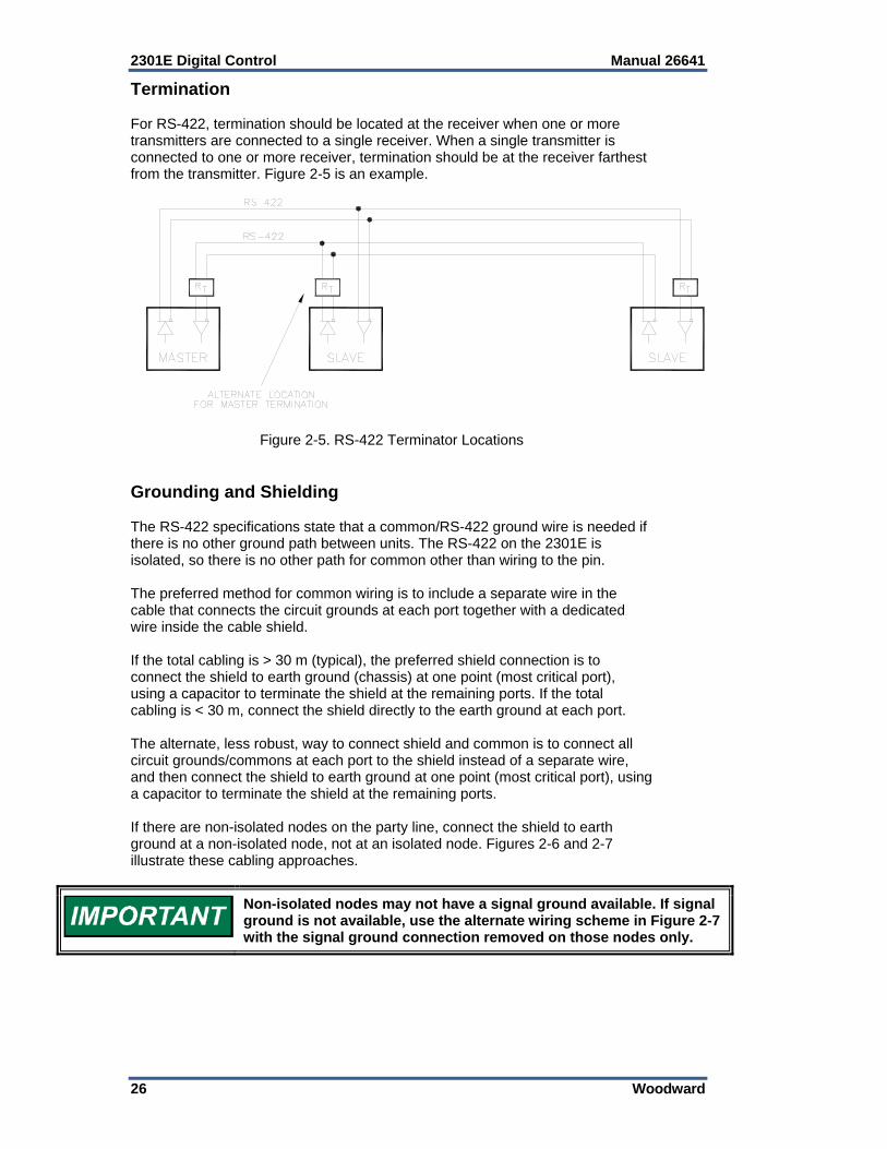
2301E Digital Control Manual 26641
26 Woodward
Termination For RS-422, termination should be located at the receiver when one or more transmitters are connected to a single receiver. When a single transmitter is connected to one or more receiver, termination should be at the receiver farthest from the transmitter. Figure 2-5 is an example.
Figure 2-5. RS-422 Terminator Locations
Grounding and Shielding The RS-422 specifications state that a common/RS-422 ground wire is needed if there is no other ground path between units. The RS-422 on the 2301E is isolated, so there is no other path for common other than wiring to the pin. The preferred method for common wiring is to include a separate wire in the cable that connects the circuit grounds at each port together with a dedicated wire inside the cable shield. If the total cabling is > 30 m (typical), the preferred shield connection is to connect the shield to earth ground (chassis) at one point (most critical port), using a capacitor to terminate the shield at the remaining ports. If the total cabling is < 30 m, connect the shield directly to the earth ground at each port. The alternate, less robust, way to connect shield and common is to connect all circuit grounds/commons at each port to the shield instead of a separate wire, and then connect the shield to earth ground at one point (most critical port), using a capacitor to terminate the shield at the remaining ports. If there are non-isolated nodes on the party line, connect the shield to earth ground at a non-isolated node, not at an isolated node. Figures 2-6 and 2-7 illustrate these cabling approaches.
Non-isolated nodes may not have a signal ground available. If signal ground is not available, use the alternate wiring scheme in Figure 2-7 with the signal ground connection removed on those nodes only.
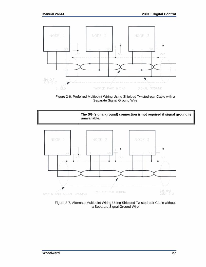
Manual 26641 2301E Digital Control
Woodward 27
Figure 2-6. Preferred Multipoint Wiring Using Shielded Twisted-pair Cable with a
Separate Signal Ground Wire
The SG (signal ground) connection is not required if signal ground is unavailable.
Figure 2-7. Alternate Multipoint Wiring Using Shielded Twisted-pair Cable without
a Separate Signal Ground Wire

2301E Digital Control Manual 26641
28 Woodward
Installation Check-out Procedure With the installation completed as described in this section, perform the following check-out procedure before beginning the start-up adjustments in Chapter 5. Visual Inspection 1. Check the linkage between the actuator and the prime mover for looseness
or binding. Refer to the appropriate actuator manual and to manual 25070, Electric Governor Installation Guide, for additional information on the linkage.
The actuator lever should be near but not at the minimum position when the fuel or steam rack is at the minimum position. If the actuator lever gets to its minimum position before completely shutting off fuel or steam, the control may not be able to shut down the prime mover, causing damage to equipment or injury or death.
2. Check for correct wiring in accordance with the plant wiring diagram, Figure
1-2. 3. Check for broken terminals and loose terminal screws. 4. Check the speed sensor for visible damage. Check the clearance of the
magnetic pickup between the gear and the sensor, and adjust if necessary. Clearance should be between 0.25 and 1.0 mm (0.010 and 0.040 inch) at the closest point. Make sure the gear has less than 0.5 mm (0.020 inch) diametric run-out. See manual 82510, Magnetic Pickups and Proximity Switches for Electric Governors.

Manual 26641 2301E Digital Control
Woodward 29
Chapter 3. Description of Operation
Introduction
An unsafe condition could occur with improper use of these software tools. Only trained personnel should have access to these tools.
This chapter provides an overview of the features and operation of the 2301E Load Sharing and Speed Control. The 2301E Load Sharing and Speed Control uses a 32 bit microprocessor for all control functions. All control adjustments are made with an external computer that communicates with the control via a serial port. The external computer can be disconnected from the control during normal operation, to provide security against tampering. The speed and load sharing section of these 2301E models monitors and controls two functions: Speed The speed control section keeps the prime mover at the correct speed. Load Control The load control section manages the prime mover load based on the load control mode: During parallel operation of two or more generators, the load sharing section
senses the load carried by its generator and causes the loads of all generators in the system to be shared proportionally.
During parallel operation of two or more generator or a generator paralleled against an infinite bus the control may be operated in Baseload mode.
During parallel operation of two or more generator or a generator paralleled against an infinite bus the control may be operated in Droop mode
Speed Control The Speed Control system as shown in Figure 3-1 consists of: A device (1) to sense the speed of the prime mover A frequency sensor to software converter (2) A speed reference [software] (3) to which the prime mover speed can be
compared A speed summer/amplifier [software] (4) with an output [software to
hardware] proportional to the amount of fuel or steam required to maintain the desired speed at any given load
An actuator (5) to position the fuel or steam mechanism of the prime mover A speed-sensing device, such as a magnetic pickup, senses the speed of the prime mover, and converts it to an ac signal with a frequency proportional to prime mover speed. The frequency-to-software receives the ac signal from the speed sensor and changes it to a digital number representing prime mover rpm.
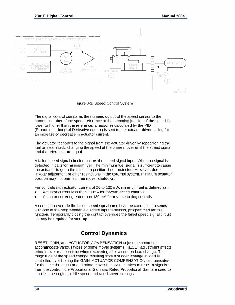
2301E Digital Control Manual 26641
30 Woodward
Figure 3-1. Speed Control System
The digital control compares the numeric output of the speed sensor to the numeric number of the speed reference at the summing junction. If the speed is lower or higher than the reference, a response calculated by the PID (Proportional-Integral-Derivative control) is sent to the actuator driver calling for an increase or decrease in actuator current. The actuator responds to the signal from the actuator driver by repositioning the fuel or steam rack, changing the speed of the prime mover until the speed signal and the reference are equal. A failed speed signal circuit monitors the speed signal input. When no signal is detected, it calls for minimum fuel. The minimum fuel signal is sufficient to cause the actuator to go to the minimum position if not restricted. However, due to linkage adjustment or other restrictions in the external system, minimum actuator position may not permit prime mover shutdown. For controls with actuator current of 20 to 160 mA, minimum fuel is defined as: Actuator current less than 10 mA for forward-acting controls Actuator current greater than 180 mA for reverse-acting controls A contact to override the failed speed signal circuit can be connected in series with one of the programmable discrete input terminals, programmed for this function. Temporarily closing the contact overrides the failed speed signal circuit as may be required for start-up.
Control Dynamics RESET, GAIN, and ACTUATOR COMPENSATION adjust the control to accommodate various types of prime mover systems. RESET adjustment affects prime mover reaction time when recovering after a sudden load change. The magnitude of the speed change resulting from a sudden change in load is controlled by adjusting the GAIN. ACTUATOR COMPENSATION compensates for the time the actuator and prime mover fuel system takes to react to signals from the control. Idle Proportional Gain and Rated Proportional Gain are used to stabilize the engine at idle speed and rated speed settings.

Manual 26641 2301E Digital Control
Woodward 31
Constant dynamics refers to dynamics parameters that will remain constant as entered and do not vary with engine speed. Dynamics may be configured to vary with load by using the 5-Gain mapped dynamics. Constant dynamics are useful for fuel systems and processes that tend to be equally stable throughout the prime movers speed and load range. Variable dynamics vary gain by the ratio of actual engine speed to rated speed. The 5 point Gain mapped dynamics is a two-dimensional curve with five breakpoints that vary gain as a function of fuel demand or kW. The 5 point Gain mapped dynamics compensate for non-linear fuel systems and are useful for engines or processes whose dynamics change in a non-linear manner with load. The control can automatically switch between two gain settings, based on engine speed error, to provide improved transient load performance. Speed error is the difference between the speed reference and engine speed. The control automatically increases gain by an adjustable ratio when a speed error exceeding an adjustable window occurs (See Figure 3-2). During steady-state constant-load operation, the control uses the base gain setting. This base gain is adjusted by the user to a value which prevents the control from responding to minor speed fluctuations inherent with reciprocating engines. This feature essentially eliminates harmful jiggle of the actuator and fuel system linkage. When the speed error exceeds an adjustable window width (e.g., during a load transient), the control automatically increases gain by an adjustable ratio. This increased gain produces a faster fuel response and quickly restores engine speed at the speed reference. The base gain is restored once the control senses a return to steady-state operation. This feature is available for all gain choices. Furthermore, this feature is active when paralleled to a utility grid. Although actual engine speed does not change, the speed reference is changed when corrective bias signals are applied by load sharing or droop during load transients. Large corrective bias signals will produce a large speed error to automatically increase gain. The control also provides a second complete set of dynamic adjustments which are selected when the CB Aux discrete input is activated. Two sets of dynamics are useful where engine operating conditions change, such as in electrical power generation systems where the unit operation changes when in parallel with a bus.
Minimum Fuel Function The Minimum Fuel Function brings the fuel demand to zero. This occurs when the Close to Run discrete input goes FALSE. It also occurs if the speed sensor input has failed when the Close MPU Fail Override B input is FALSE. The Close to Run command is the preferred means for a normal shutdown of the engine. The logic function of this input can be set for normally open or normally closed.
The Close to Run discrete input is not intended for use as the sole means of shutdown in any emergency stop sequence. To prevent possible serious injury and engine damage from an over-speeding engine, do NOT use the Close to Run discrete input as the sole means of shutdown in any emergency stop sequence.
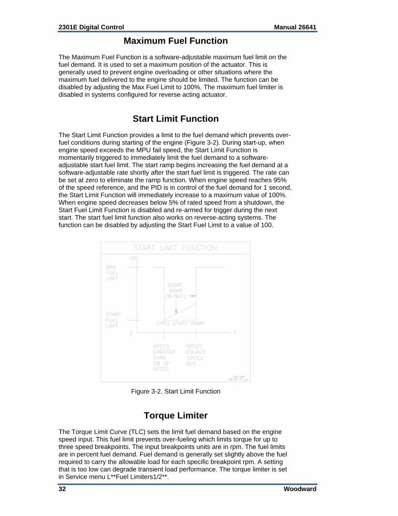
2301E Digital Control Manual 26641
32 Woodward
Maximum Fuel Function The Maximum Fuel Function is a software-adjustable maximum fuel limit on the fuel demand. It is used to set a maximum position of the actuator. This is generally used to prevent engine overloading or other situations where the maximum fuel delivered to the engine should be limited. The function can be disabled by adjusting the Max Fuel Limit to 100%. The maximum fuel limiter is disabled in systems configured for reverse acting actuator.
Start Limit Function The Start Limit Function provides a limit to the fuel demand which prevents over-fuel conditions during starting of the engine (Figure 3-2). During start-up, when engine speed exceeds the MPU fail speed, the Start Limit Function is momentarily triggered to immediately limit the fuel demand to a software-adjustable start fuel limit. The start ramp begins increasing the fuel demand at a software-adjustable rate shortly after the start fuel limit is triggered. The rate can be set at zero to eliminate the ramp function. When engine speed reaches 95% of the speed reference, and the PID is in control of the fuel demand for 1 second, the Start Limit Function will immediately increase to a maximum value of 100%. When engine speed decreases below 5% of rated speed from a shutdown, the Start Fuel Limit Function is disabled and re-armed for trigger during the next start. The start fuel limit function also works on reverse-acting systems. The function can be disabled by adjusting the Start Fuel Limit to a value of 100.
Figure 3-2. Start Limit Function
Torque Limiter The Torque Limit Curve (TLC) sets the limit fuel demand based on the engine speed input. This fuel limit prevents over-fueling which limits torque for up to three speed breakpoints. The input breakpoints units are in rpm. The fuel limits are in percent fuel demand. Fuel demand is generally set slightly above the fuel required to carry the allowable load for each specific breakpoint rpm. A setting that is too low can degrade transient load performance. The torque limiter is set in Service menu L**Fuel Limiters1/2**.
Manual 26641 2301E Digital Control
Woodward 33
Manifold Air Pressure Limiter The Manifold Air Pressure (MAP) Limiter sets the fuel limit based on the air pressure in the engine manifold. This fuel limit prevents over-fueling when air pressure is low. A five breakpoint pressure curve is available. Setting up this limiter will also prevent excessive smoke. The fuel limits are in percent fuel demand. An overload switch can be used to indicate that the engine is near the maximum manifold air pressure limit. Setting up the MAP limiter see service menu M**Fuel Limiters 2/2**.
Speed/Load Reference and Ramps The 2301E control provides local control with discrete inputs for raising and lowering speed/load. For remote speed/load setting, the control provides a remote reference analog input. Input functions are enabled as follows: Local Speed/Load Reference Raise/Lower discrete inputs control the speed
ramp inputs when the CB Aux input is open. Remote Speed/Load Reference setting is enabled when the Raise
Speed/Load and Lower Speed/Load contacts are both closed, the Rated contact is closed, and Remote Reference input is selected as Speed Reference setting or as Baseload reference setting.
Speed Reference and Ramp Functions This section describes the operation of the speed reference and ramp functions and their relation to each other. Read this section carefully to be sure your sequencing provides the proper operating modes. The control provides start, idle, lower limit, raise limit, and rated set points, accel and decel times, and raise and lower rates, for local operation. Accel time determines the time required for the engine to ramp from start to idle speed and from idle to rated speed. Decel time determines the time required for the engine to ramp from rated speed to idle speed. Raise and lower rates determine how fast speed is increased or decreased by raise and lower discrete input commands. The Start Speed can be enabled for applications which require this function (e.g., spark gas reciprocating engines).The start speed set point provides a speed reference above cranking speed but below the speed achieved with the start fuel limit setting (light-off speed). This function is configurable. The default has this function disabled. When configured TRUE, the start reference is selected by control power-up, engine not running, or engine cranking. The Start reference is the speed reference until the engine starts. After the engine speed exceeds the start speed set point the speed will accelerate by a controlled ramp to the reference selected by the Idle/Rated contact input. This may not be the desired mode of operation, so be sure to understand the implications of operating the control in this manner.

2301E Digital Control Manual 26641
34 Woodward
The idle speed set point is provided for engine warm-up or cool-down cycles. Idle speed may be set equal to or less than the rated speed set point. Idle is independent of the lower limit set point and may be set at a lower speed. The idle speed set point is selected when the Rated contact is open, if the start reference is removed either by configuration or engine speed above start speed. Closing the Rated contact ramps the speed set point from idle to rated, if the start reference is removed. Closing either the raise or lower contacts while ramping from idle to rated results in immediate cancellation of the idle to rated ramp, and the ramp will stop at that point. After acceleration to rated speed is completed, the raise and lower commands increase and decrease engine speed based on the raise and lower rate settings. The raise and lower commands will not increase the speed reference above the raise limit or below the lower limit. The raise and lower commands can be used as speed trim inputs for manual synchronization. Or if the system uses droop operation for paralleling, the raise and lower inputs will be load setting inputs. If remote speed setting operation is configured and enabled after the engine reaches rated speed, the control will ramp speed to the reference value set by the Remote Reference input at the Remote Reference increase or decrease time settings. The Remote Reference range is selectable and can be configured for one of two operating ranges: from 4 to 20 mA or 1 to 5 V. The minimum input value (4 mA or 1 V) Remote Reference set point may be set to a lower or higher speed than the high input (20 mA or 5 V) set point, providing for either direct or reverse-acting remote speed setting. If the Remote Speed Reference input is configured and enabled when the Idle/Rated contact is closed or during the idle to rated ramp, the speed reference will ramp to the Remote Reference input value at the remote reference increase or decrease rate settings. This may not be the desired mode of operation, so be sure to understand the implications of operating the control in this manner. If a difference is detected between the present speed reference and the remote reference rpm value, the present speed reference is ramped up or down at the increase or decrease rate until the present speed reference matches the remote speed reference rpm value. The remote reference will not increase/decrease the speed reference above the maximum input value or below the minimum input value. (see Figure 3-3).
Figure 3-3. Remote Speed Reference
Manual 26641 2301E Digital Control
Woodward 35
Speed Bias and Synchronizer Summing There are three functions that can change the speed reference from the set point that was determined in the above paragraphs: Synchronizer bias input Load bias input Auxiliary bias input The synchronizer input is used to match the prime movers speed and generator phase with bus that it is being paralleled to. Analog input #1 at terminals 19, 20, and 21 is used as the synchronizer input. The sensitivity of the synchronizer can be adjusted. The load bias is the signal from the load control function that will bias the speed reference to increase or decrease the speed or generator load. When the generator is paralleled to other units, a change in speed reference bias will result in a change in generator load, in an isolated generator the load bias will give a change in speed (droop). The third speed bias can occur when the control is configured for Analog input #2 to come from an auxiliary load control device. This external control will affect the speed reference as required depending on its load control mode.
Load Reference and Ramp Functions This section describes the operation of the load reference and ramp functions and their relation to each other. Droop operating mode has no ramp functions and is not included here. Isochronous load sharing descriptions apply to two or more units paralleled on a common isolated bus or by accessory device with the utility. Baseload descriptions apply to a unit paralleled with the utility or with one or more units on an isolated bus. Read this section carefully to be sure your sequencing provides the proper operating modes. The control provides an unload trip level set point, baseload set point, rated load set point, loading rate, unloading rate, and fast loading rate. Loading rate determines the kW per second increase when the load input is closed. Unloading rate determines the kW per second decrease when the load input is opened (unload). The 2nd loading rate (usually a fast kW/sec rate) is enabled by the Enable fast load rate prompt to TRUE in the LOAD SETTING menu, and setting a system load percent level which will activate the fast load rate. This mode could be useful in an emergency start situation where the generator set could be loaded at a fast rate. When the system load is high, the oncoming generator will load at a fast rate to assume it share of the load quicker. In the isochronous mode (CB Aux input closed), closing the load contact ramps the load set point from no-load to the load sharing setting. Opening the load contact (unload) ramps the load to the unload trip level setting. At the unload trip level a Circuit Breaker open signal is issued. Closing the baseload contact ramps the load set point from no-load or the load sharing setting to the baseload reference. Opening the baseload contact ramps the load to the load sharing setting.
2301E Digital Control Manual 26641
36 Woodward
When in baseload operation, the baseload reference determines the load on the generator without regard to other units connected to the same load. When the generator is carrying less load than the base load reference, the load bias is positive and the closed loop path increases the fuel to the engine. When the generator is carrying more load than the base load reference, the load bias is negative and the closed loop path will decrease the fuel to the engine. As the fuel to the engine is changed, the load and/or speed will change until the engine speed exactly matches the biased speed reference. At this steady state base load condition, the load bias is virtually zero and the biased speed reference, rated speed reference, and engine speed are virtually equal. Opening the baseload input contact ramps the generator load from base load back into isochronous load sharing. However, opening the load input contact (unload) instead, ramps the generator load from the base load setting to the unload trip level where a breaker trip signal is issued after a tunable time delay.
In isolated bus applications, a brief speed transient may occur when the load sharing relay closes following transfer from baseload back into isochronous load sharing.
It is possible for the control to be in base load control while supplying power to a load which is isolated from the infinite bus. The capability of the engine generator must be considered when operating this way. As an example consider two generators, one capable of providing 1200 kW and one capable of providing 600 kW. If the combined load demand to these generators is 750 kW while the 1200 kW generator is in steady state isochronous load sharing and the 600 kW generator is in steady state base load with a set point of 250 kW, the 1200 kW generator will again be carrying 500 kW and the 600 kW generator will again be carrying 250 kW. However, now as the total load demand increases only the 1200 kW generator will respond to the increase. At a combined load demand of 1450 kW, the 1200 kW generator will carry 1200 kW while the 600 kW generator in base load will still be carrying 250 kW. If the load demand exceeds 1450 kW, the steady state frequency of the bus will decrease and the load supplied by each individual generator will increase. Soft Loading The load command discrete input contact controls soft loading. If the load command discrete input is closed when the breaker (CB AUX) input contact closes, the generator will soft load to the reference level of the mode selected (load sharing or base load). If the load command discrete input is open (unload) when the breaker (CB AUX) closes, the generator will immediately load to the Unload Trip Level set in the KW Setting menu. When the load command discrete input is closed, the generator will soft load to the reference level of the mode selected (load sharing or base load). The ramp rate is adjustable. Soft Unloading and Open Generator Breaker Relay Output

Manual 26641 2301E Digital Control
Woodward 37
If the load command discrete input contact is opened (unload) while the breaker (CB AUX) input contact is closed, the generator will soft unload from the present load level to the unload trip level. Once the generator load has reached the unload trip level or the reference has been there for 5 seconds(tunable), the Open Gen Breaker relay output will open for 1 second (tunable). The load command discrete input must be maintained OPEN to complete the unload sequence.
The Load Command discrete input must be maintained logic to operate the Soft Loading/Unloading sequence. The input must be OPEN to complete the Unload sequence and disconnect the generator. The input must be CLOSED to complete the Load sequence and operate the generator in Isochronous Load Sharing or Base Load operating mode.
CB AUX Base Load
Load Gen
Lower Spd/Ld
Raise Spd/Ld
Operation of Load Control
F X X X X Droop F X X T F Droop lower load F X X F T Droop raise load F X X T T Droop remote load ref T F T X X Isochronous load sharing T T T X X Base load T T T F F Base load ref will ramp to
internal base load reference T T T F T Base load ref will ramp toward
rated load T T T T F Base load ref will ramp toward
the unload trip level T T T T T Base load ref will ramp to value
of remote load set point T X F X X Base load control at the unload
trip level T X T-F X X Load will ramp to unload trip
level and open gen breaker Legend: F=False, T=True, X=Don’t Care
Table 3-1. Description of Discrete Inputs While in Load Control
Droop Function Load control operations are not functional while in droop. The speed reference must be changed to increase or decrease the generator load while in droop. The base load and the load discrete inputs have no effect while operating in the droop mode. The CB Aux contact switches between load control and droop operation. The droop function supplies a feedback path to bias the speed reference. The function of droop is to decrease the speed reference as the load increases. This is done by negatively biasing the output of the speed reference with the droop function. The CB Aux discrete input contact is used to switch the droop function on and off. The droop function can be permanently enabled by leaving the CB Aux contact discrete input false. A complete discussion of droop operation is included in the Power System Management Concepts section.
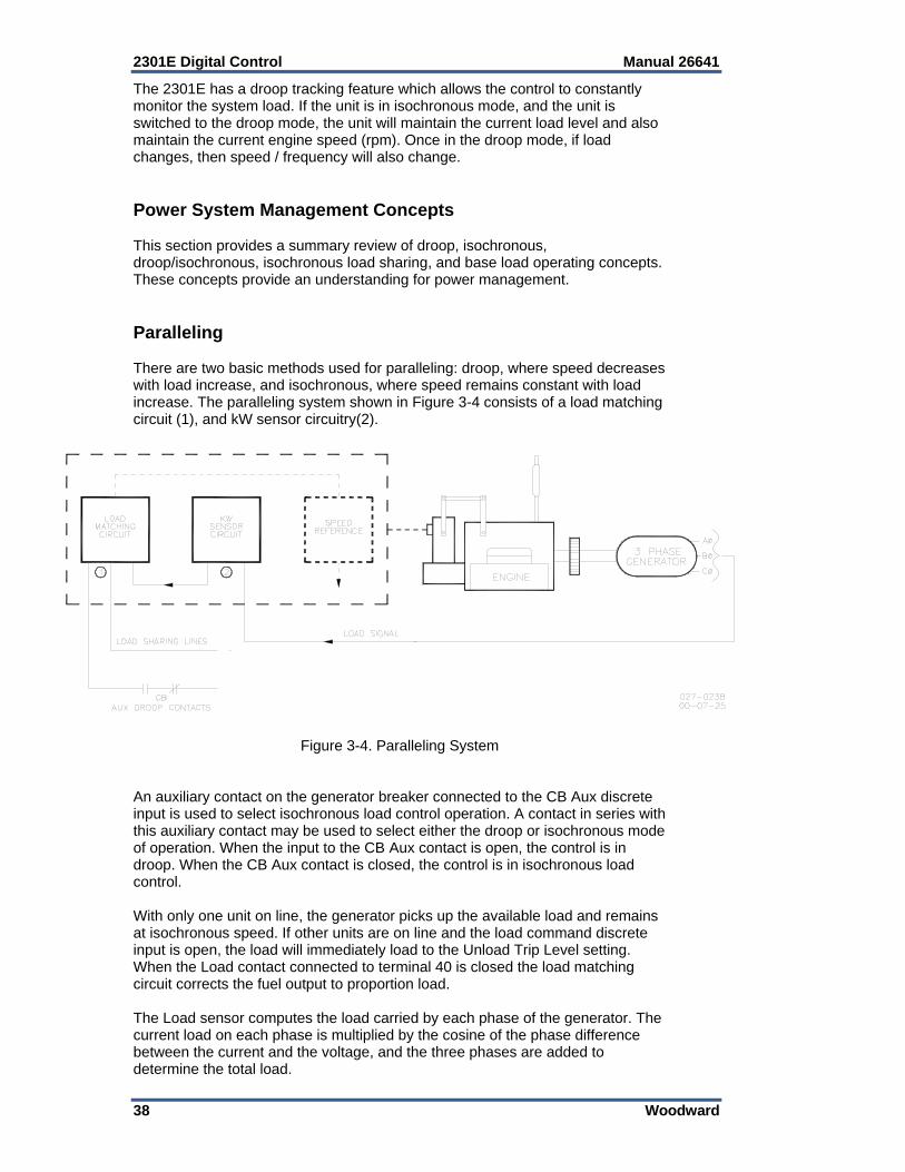
2301E Digital Control Manual 26641
38 Woodward
The 2301E has a droop tracking feature which allows the control to constantly monitor the system load. If the unit is in isochronous mode, and the unit is switched to the droop mode, the unit will maintain the current load level and also maintain the current engine speed (rpm). Once in the droop mode, if load changes, then speed / frequency will also change. Power System Management Concepts This section provides a summary review of droop, isochronous, droop/isochronous, isochronous load sharing, and base load operating concepts. These concepts provide an understanding for power management. Paralleling There are two basic methods used for paralleling: droop, where speed decreases with load increase, and isochronous, where speed remains constant with load increase. The paralleling system shown in Figure 3-4 consists of a load matching circuit (1), and kW sensor circuitry(2).
Figure 3-4. Paralleling System
An auxiliary contact on the generator breaker connected to the CB Aux discrete input is used to select isochronous load control operation. A contact in series with this auxiliary contact may be used to select either the droop or isochronous mode of operation. When the input to the CB Aux contact is open, the control is in droop. When the CB Aux contact is closed, the control is in isochronous load control. With only one unit on line, the generator picks up the available load and remains at isochronous speed. If other units are on line and the load command discrete input is open, the load will immediately load to the Unload Trip Level setting. When the Load contact connected to terminal 40 is closed the load matching circuit corrects the fuel output to proportion load. The Load sensor computes the load carried by each phase of the generator. The current load on each phase is multiplied by the cosine of the phase difference between the current and the voltage, and the three phases are added to determine the total load.
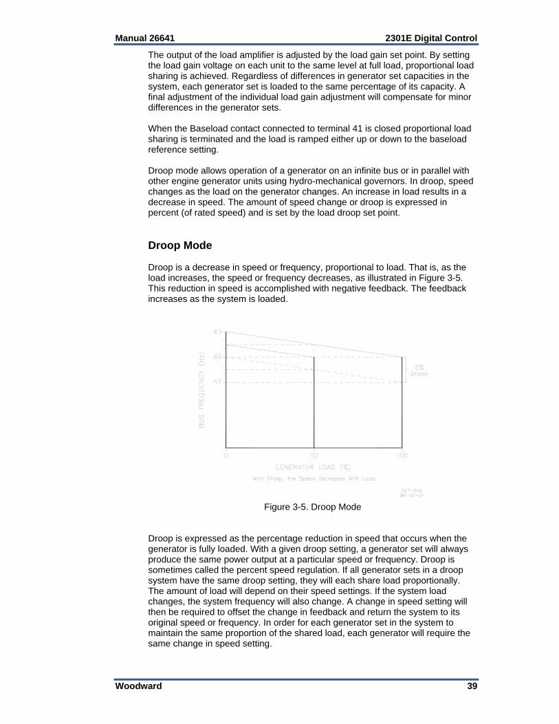
Manual 26641 2301E Digital Control
Woodward 39
The output of the load amplifier is adjusted by the load gain set point. By setting the load gain voltage on each unit to the same level at full load, proportional load sharing is achieved. Regardless of differences in generator set capacities in the system, each generator set is loaded to the same percentage of its capacity. A final adjustment of the individual load gain adjustment will compensate for minor differences in the generator sets. When the Baseload contact connected to terminal 41 is closed proportional load sharing is terminated and the load is ramped either up or down to the baseload reference setting. Droop mode allows operation of a generator on an infinite bus or in parallel with other engine generator units using hydro-mechanical governors. In droop, speed changes as the load on the generator changes. An increase in load results in a decrease in speed. The amount of speed change or droop is expressed in percent (of rated speed) and is set by the load droop set point. Droop Mode Droop is a decrease in speed or frequency, proportional to load. That is, as the load increases, the speed or frequency decreases, as illustrated in Figure 3-5. This reduction in speed is accomplished with negative feedback. The feedback increases as the system is loaded.
Figure 3-5. Droop Mode
Droop is expressed as the percentage reduction in speed that occurs when the generator is fully loaded. With a given droop setting, a generator set will always produce the same power output at a particular speed or frequency. Droop is sometimes called the percent speed regulation. If all generator sets in a droop system have the same droop setting, they will each share load proportionally. The amount of load will depend on their speed settings. If the system load changes, the system frequency will also change. A change in speed setting will then be required to offset the change in feedback and return the system to its original speed or frequency. In order for each generator set in the system to maintain the same proportion of the shared load, each generator will require the same change in speed setting.
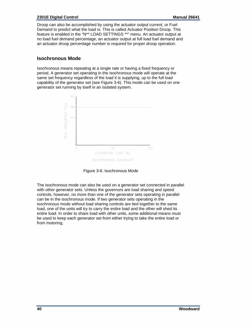
2301E Digital Control Manual 26641
40 Woodward
Droop can also be accomplished by using the actuator output current, or Fuel Demand to predict what the load is. This is called Actuator Position Droop. This feature is enabled in the “N** LOAD SETTINGS **” menu. An actuator output at no load fuel demand percentage, an actuator output at full load fuel demand and an actuator droop percentage number is required for proper droop operation. Isochronous Mode Isochronous means repeating at a single rate or having a fixed frequency or period. A generator set operating in the isochronous mode will operate at the same set frequency regardless of the load it is supplying, up to the full load capability of the generator set (see Figure 3-6). This mode can be used on one generator set running by itself in an isolated system.
Figure 3-6. Isochronous Mode The isochronous mode can also be used on a generator set connected in parallel with other generator sets. Unless the governors are load sharing and speed controls, however, no more than one of the generator sets operating in parallel can be in the isochronous mode. If two generator sets operating in the isochronous mode without load sharing controls are tied together to the same load, one of the units will try to carry the entire load and the other will shed its entire load. In order to share load with other units, some additional means must be used to keep each generator set from either trying to take the entire load or from motoring.
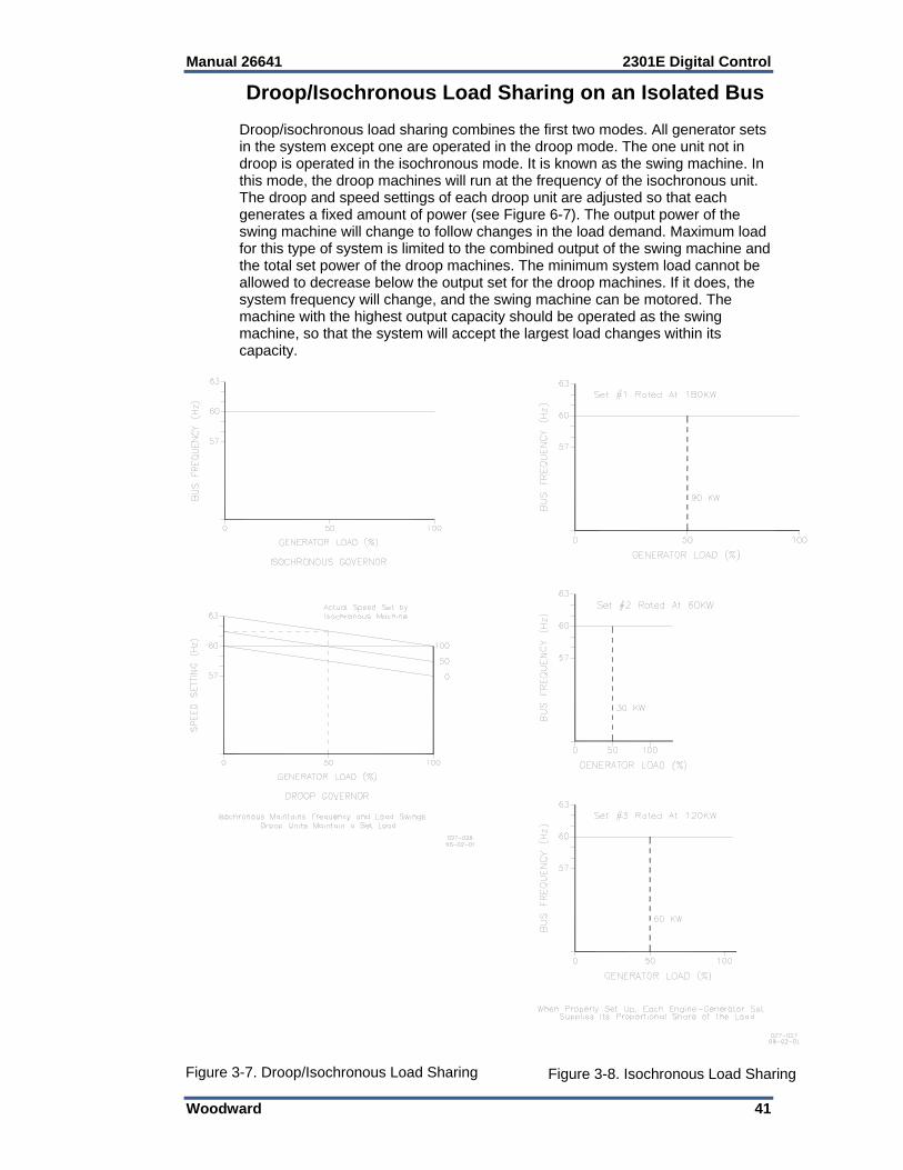
Manual 26641 2301E Digital Control
Woodward 41
Droop/Isochronous Load Sharing on an Isolated Bus Droop/isochronous load sharing combines the first two modes. All generator sets in the system except one are operated in the droop mode. The one unit not in droop is operated in the isochronous mode. It is known as the swing machine. In this mode, the droop machines will run at the frequency of the isochronous unit. The droop and speed settings of each droop unit are adjusted so that each generates a fixed amount of power (see Figure 6-7). The output power of the swing machine will change to follow changes in the load demand. Maximum load for this type of system is limited to the combined output of the swing machine and the total set power of the droop machines. The minimum system load cannot be allowed to decrease below the output set for the droop machines. If it does, the system frequency will change, and the swing machine can be motored. The machine with the highest output capacity should be operated as the swing machine, so that the system will accept the largest load changes within its capacity.
Figure 3-7. Droop/Isochronous Load Sharing
Figure 3-8. Isochronous Load Sharing
2301E Digital Control Manual 26641
42 Woodward
Isochronous Load Sharing on an Isolated Bus Isochronous load sharing operates all generator sets in a system in the isochronous mode. Load sharing is accomplished by adding a load sensor to each electric isochronous governor. The load sensors are interconnected by the load sharing lines. Any imbalance in load between units will cause a change to the regulating circuit in each governor. While each unit continues to run at isochronous speed, these changes force each machine to supply a proportional share of power to meet the total load demand on the system (see Figure 3-8). Base Load on an Isolated Bus Base Load is a method of setting a base or fixed load on a machine operating in parallel with an isolated bus. This is accomplished by using an isochronous load control and providing a reference at which to control the load. The governor will force the generator output to increase or decrease until the output of the load sensor is equal to the reference setting. At this point, the system is in balance. This method can only be used where other generator sets are producing enough power to meet the changes in load demand. This operating mode is ideal for either soft loading additional units into an isochronous system, or for de-rating or unloading a machine. Base Load Base Load for a system paralleled to an infinite bus or utility is the same as base load in an isolated system. The advantage of base loading over droop is that when separating from a utility, there is no frequency change. Simply removing the bias signal on breaking from the utility returns the system to isochronous.
Actuator Droop Droop is dependent on load (this is the measured kW) or on the actuator position. As already mentioned, droop based on the measured load in kW by the PTs and CTs (terminals 1 to 9) of the 2301E is used. With actuator droop the speed reference is decreased when the actuator output increases. In Menu G**Speed Setting** the minimum and maximum actuator position settings are adjusted. The droop function is active from this minimum position (actuator at rated speed, no load) to the maximum actuator position (actuator at rated speed, full load). The droop is a percentage of the rated speed. When droop is set at 0 there is no actuator droop. For example: Rated speed is set for 900 rpm. Droop is set for 3%. Speed reference is at maximum actuator position = 900—27 = 873 rpm.
Manual 26641 2301E Digital Control
Woodward 43
Load Pulse / Load Rejection Load Pulse The load pulse logic has been tested in August 2002 on a DG-set. Activating the load pulse logic did not result in significant improvement of load-acceptance. There was improvement on the load-rejection tests. The load pulse logic measures how fast the engine load changes in time. When a large increase in engine load is detected, then the speed reference output is increased momentarily to compensate for a drop in speed. Load Rejection If a large decrease in engine load is detected, the speed reference or actuator output is decreased momentarily to compensate for a large speed overshoot. With this logic an overshoot can be reduced or an overspeed can be prevented when an engine is at 100 % load and is unloaded instantly.

2301E Digital Control Manual 26641
44 Woodward
Chapter 4. Entering Control Set Points
Introduction This chapter contains information on control calibration. This can be done with either the Control Assistant software or the 2301E Toolkit Service Tool. Because of the variety of installations, plus system and component tolerances, the 2301E control must be tuned and configured for each system to obtain optimum performance. This chapter contains information on how to enter control set points through the control's menu system using the Control Assistant and the 2301E Toolkit Service Tool software. See Chapter 5, Initial Control Settings, and Chapter 6, Alternate Dynamic Adjustments, for prestart-up and start-up settings and adjustments.
An improperly calibrated control could cause an overspeed or other damage to the prime mover. To prevent possible serious injury from an overspeeding prime mover, read this entire procedure before starting the prime mover.
Control Assistant PC Interface The connection of a computer is only required for calibration and setup of the 2301E control on a prime mover. The computer and Control Assistant or 2301E Toolkit Service Tool software is not required, and not necessary, for normal operation of the prime mover, unless Modbus is being used for monitoring. Control Assistant is similar to the Servlink / Watch Window used on the 2301D. It provides a means of shutting down and placing the control in the I/O Lock mode for Configuration, saving values in the control EEPROM, and resetting the control. Application tunable values can be uploaded, downloaded, and saved to a file. A “WinPanel” provides a window for real-time monitoring and editing of all control Configure and Service Menu parameters and values. Tunable values can be adjusted in the WinPanel window. Control Assistant communicates with the control through an RS-232 cable “null-modem” connection to the communication port which is configured as a point-to-point only SOS Servlink OPC Server.
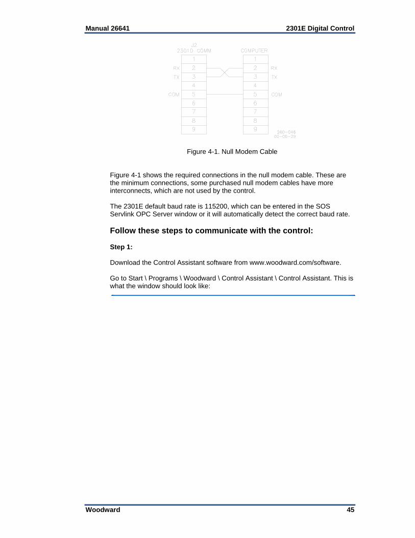
Manual 26641 2301E Digital Control
Woodward 45
Figure 4-1. Null Modem Cable Figure 4-1 shows the required connections in the null modem cable. These are the minimum connections, some purchased null modem cables have more interconnects, which are not used by the control. The 2301E default baud rate is 115200, which can be entered in the SOS Servlink OPC Server window or it will automatically detect the correct baud rate. Follow these steps to communicate with the control: Step 1: Download the Control Assistant software from www.woodward.com/software. Go to Start \ Programs \ Woodward \ Control Assistant \ Control Assistant. This is what the window should look like:
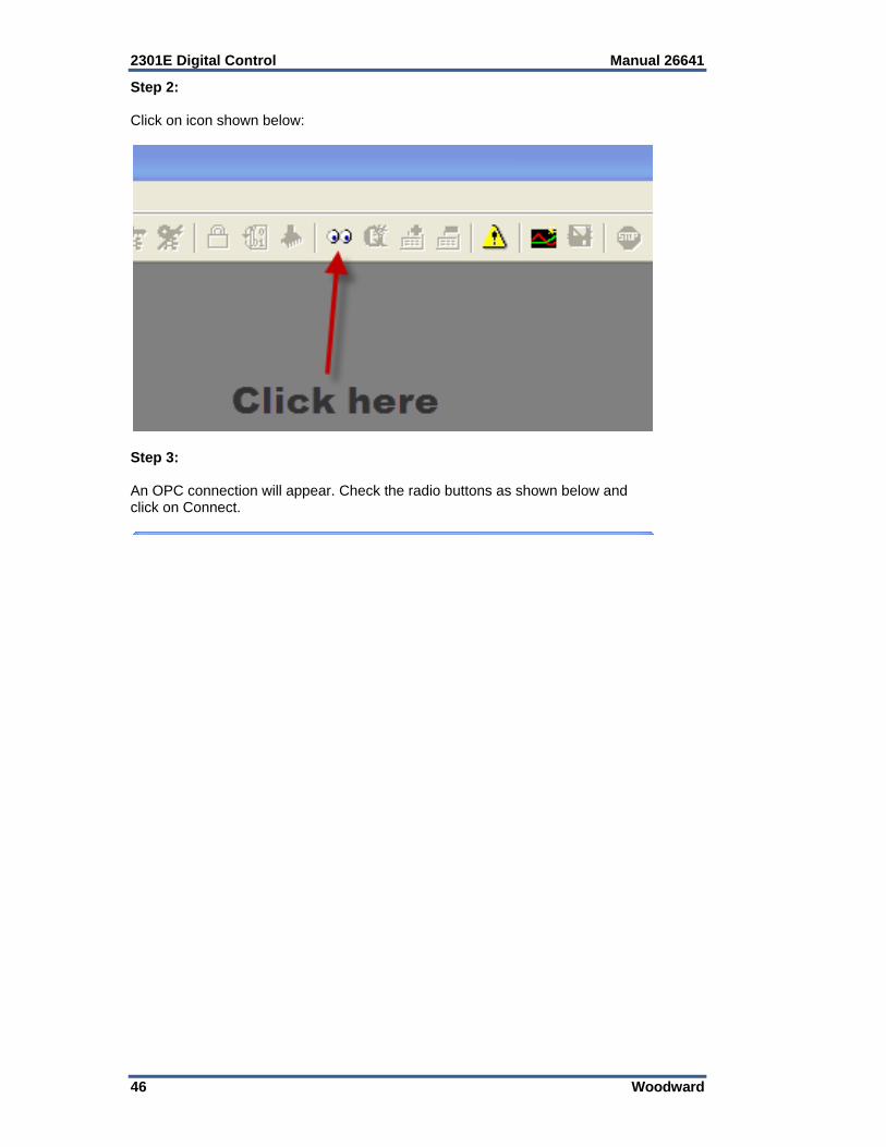
2301E Digital Control Manual 26641
46 Woodward
Step 2: Click on icon shown below:
Step 3: An OPC connection will appear. Check the radio buttons as shown below and click on Connect.

Manual 26641 2301E Digital Control
Woodward 47
Step 4: An OPC connection will be made.
Step 5: When the communication is complete, the window should look as follows:
Step 6: Minimize the SOS Servlink OPC Server program (don’t close it down).
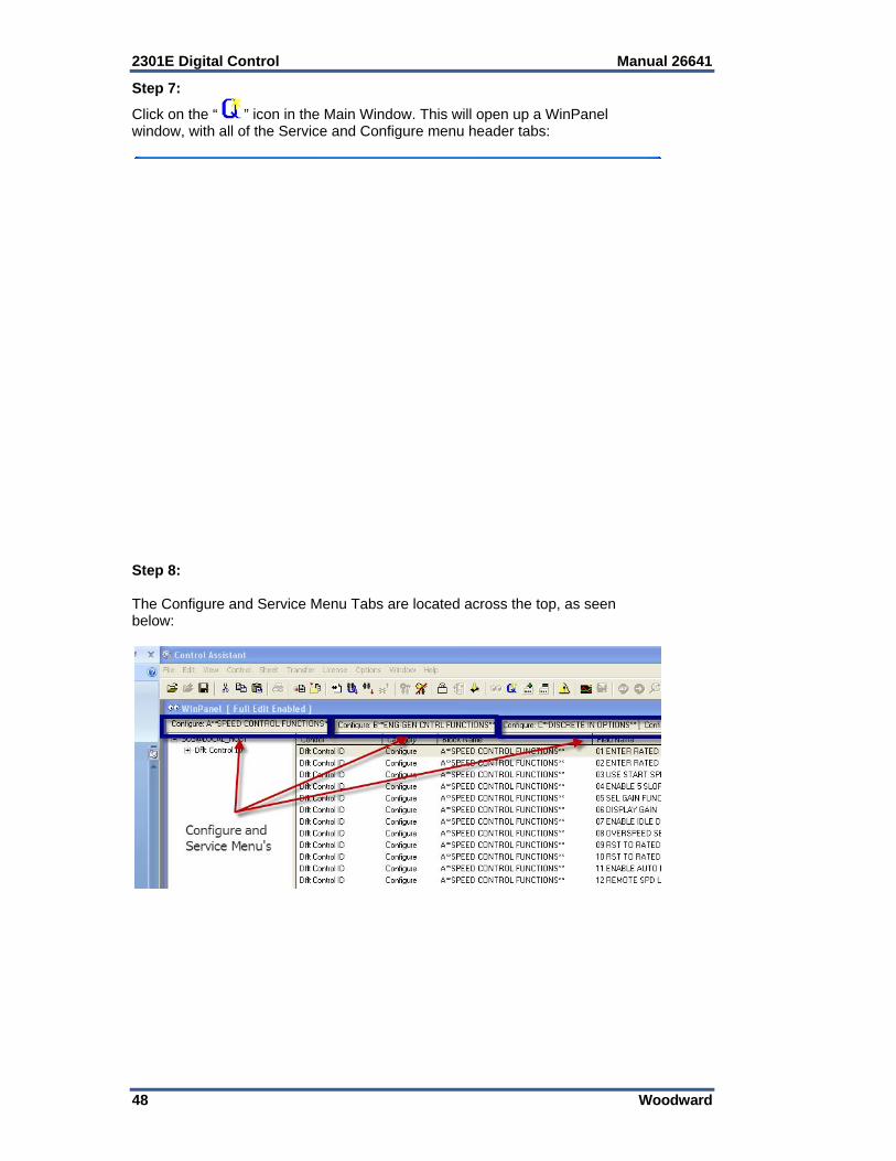
2301E Digital Control Manual 26641
48 Woodward
Step 7:
Click on the “ ” icon in the Main Window. This will open up a WinPanel window, with all of the Service and Configure menu header tabs:
Step 8: The Configure and Service Menu Tabs are located across the top, as seen below:
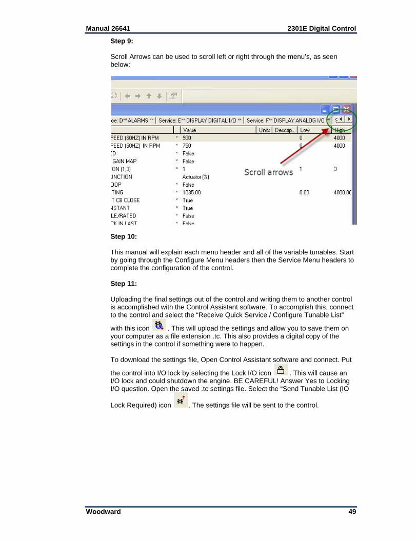
Manual 26641 2301E Digital Control
Woodward 49
Step 9: Scroll Arrows can be used to scroll left or right through the menu’s, as seen below:
Step 10: This manual will explain each menu header and all of the variable tunables. Start by going through the Configure Menu headers then the Service Menu headers to complete the configuration of the control. Step 11: Uploading the final settings out of the control and writing them to another control is accomplished with the Control Assistant software. To accomplish this, connect to the control and select the “Receive Quick Service / Configure Tunable List”
with this icon . This will upload the settings and allow you to save them on your computer as a file extension .tc. This also provides a digital copy of the settings in the control if something were to happen. To download the settings file, Open Control Assistant software and connect. Put
the control into I/O lock by selecting the Lock I/O icon . This will cause an I/O lock and could shutdown the engine. BE CAREFUL! Answer Yes to Locking I/O question. Open the saved .tc settings file. Select the “Send Tunable List (IO
Lock Required) icon . The settings file will be sent to the control.

2301E Digital Control Manual 26641
50 Woodward
Step 12: To upload the settings file from a 2301D to a 2301E, the same steps are applied. Not all of the settings from the 2301D are compatible with the 2301E and list will be generated with the settings that cannot be loaded. That list is shown below:
These items need to be manually loaded. Verify that these are loaded either using Control Assistant or the 2301E Service Tool.
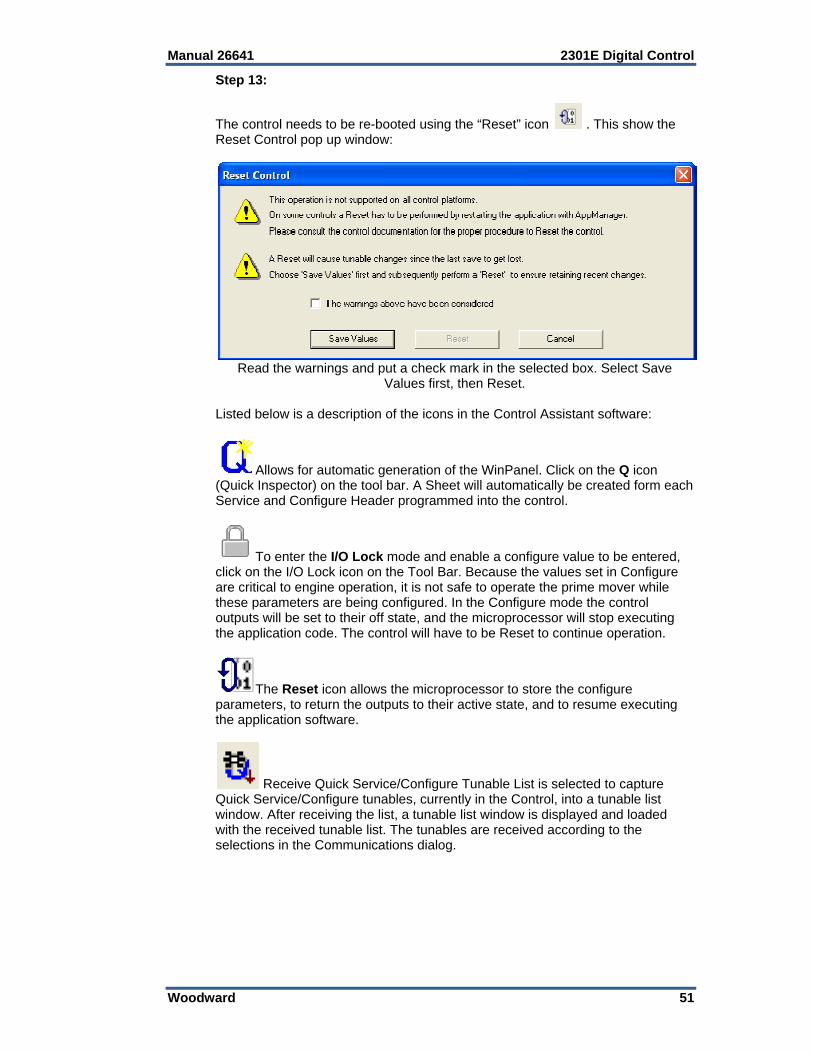
Manual 26641 2301E Digital Control
Woodward 51
Step 13:
The control needs to be re-booted using the “Reset” icon . This show the Reset Control pop up window:
Read the warnings and put a check mark in the selected box. Select Save Values first, then Reset.
Listed below is a description of the icons in the Control Assistant software:
Allows for automatic generation of the WinPanel. Click on the Q icon (Quick Inspector) on the tool bar. A Sheet will automatically be created form each Service and Configure Header programmed into the control.
To enter the I/O Lock mode and enable a configure value to be entered, click on the I/O Lock icon on the Tool Bar. Because the values set in Configure are critical to engine operation, it is not safe to operate the prime mover while these parameters are being configured. In the Configure mode the control outputs will be set to their off state, and the microprocessor will stop executing the application code. The control will have to be Reset to continue operation.
The Reset icon allows the microprocessor to store the configure parameters, to return the outputs to their active state, and to resume executing the application software.
Receive Quick Service/Configure Tunable List is selected to capture Quick Service/Configure tunables, currently in the Control, into a tunable list window. After receiving the list, a tunable list window is displayed and loaded with the received tunable list. The tunables are received according to the selections in the Communications dialog.
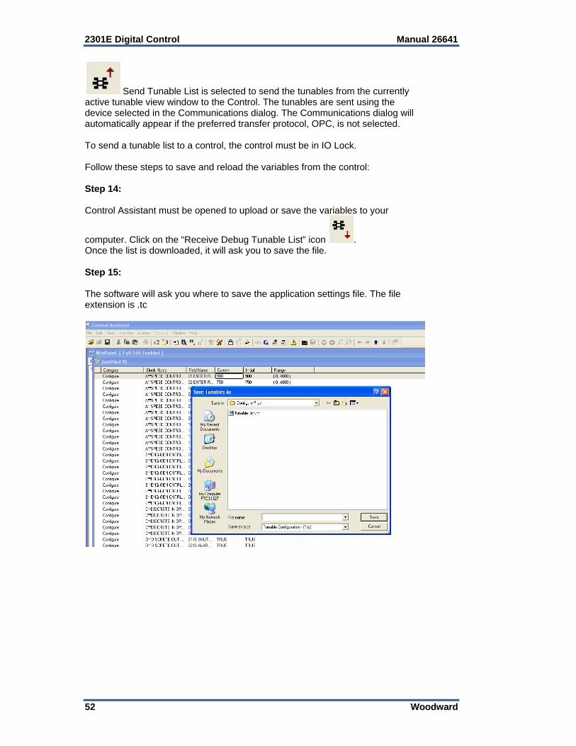
2301E Digital Control Manual 26641
52 Woodward
Send Tunable List is selected to send the tunables from the currently active tunable view window to the Control. The tunables are sent using the device selected in the Communications dialog. The Communications dialog will automatically appear if the preferred transfer protocol, OPC, is not selected. To send a tunable list to a control, the control must be in IO Lock. Follow these steps to save and reload the variables from the control: Step 14: Control Assistant must be opened to upload or save the variables to your
computer. Click on the “Receive Debug Tunable List” icon . Once the list is downloaded, it will ask you to save the file. Step 15: The software will ask you where to save the application settings file. The file extension is .tc
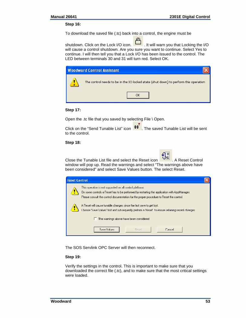
Manual 26641 2301E Digital Control
Woodward 53
Step 16: To download the saved file (.tc) back into a control, the engine must be
shutdown. Click on the Lock I/O icon. . It will warn you that Locking the I/O will cause a control shutdown. Are you sure you want to continue. Select Yes to continue. I will then tell you that a Lock I/O has been issued to the control. The LED between terminals 30 and 31 will turn red. Select OK.
Step 17: Open the .tc file that you saved by selecting File \ Open.
Click on the “Send Tunable List” icon . The saved Tunable List will be sent to the control.
Step 18:
Close the Tunable List file and select the Reset icon . A Reset Control window will pop up. Read the warnings and select “The warnings above have been considered” and select Save Values button. The select Reset.
The SOS Servlink OPC Server will then reconnect. Step 19: Verify the settings in the control. This is important to make sure that you downloaded the correct file (.tc), and to make sure that the most critical settings were loaded.
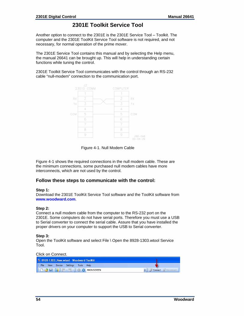
2301E Digital Control Manual 26641
54 Woodward
2301E Toolkit Service Tool Another option to connect to the 2301E is the 2301E Service Tool – Toolkit. The computer and the 2301E ToolKit Service Tool software is not required, and not necessary, for normal operation of the prime mover. The 2301E Service Tool contains this manual and by selecting the Help menu, the manual 26641 can be brought up. This will help in understanding certain functions while tuning the control. 2301E Toolkit Service Tool communicates with the control through an RS-232 cable “null-modem” connection to the communication port.
Figure 4-1. Null Modem Cable Figure 4-1 shows the required connections in the null modem cable. These are the minimum connections, some purchased null modem cables have more interconnects, which are not used by the control. Follow these steps to communicate with the control: Step 1: Download the 2301E ToolKit Service Tool software and the ToolKit software from www.woodward.com. Step 2: Connect a null modem cable from the computer to the RS-232 port on the 2301E. Some computers do not have serial ports. Therefore you must use a USB to Serial converter to connect the serial cable. Assure that you have installed the proper drivers on your computer to support the USB to Serial converter. Step 3: Open the ToolKit software and select File \ Open the 8928-1303.wtool Service Tool. Click on Connect.
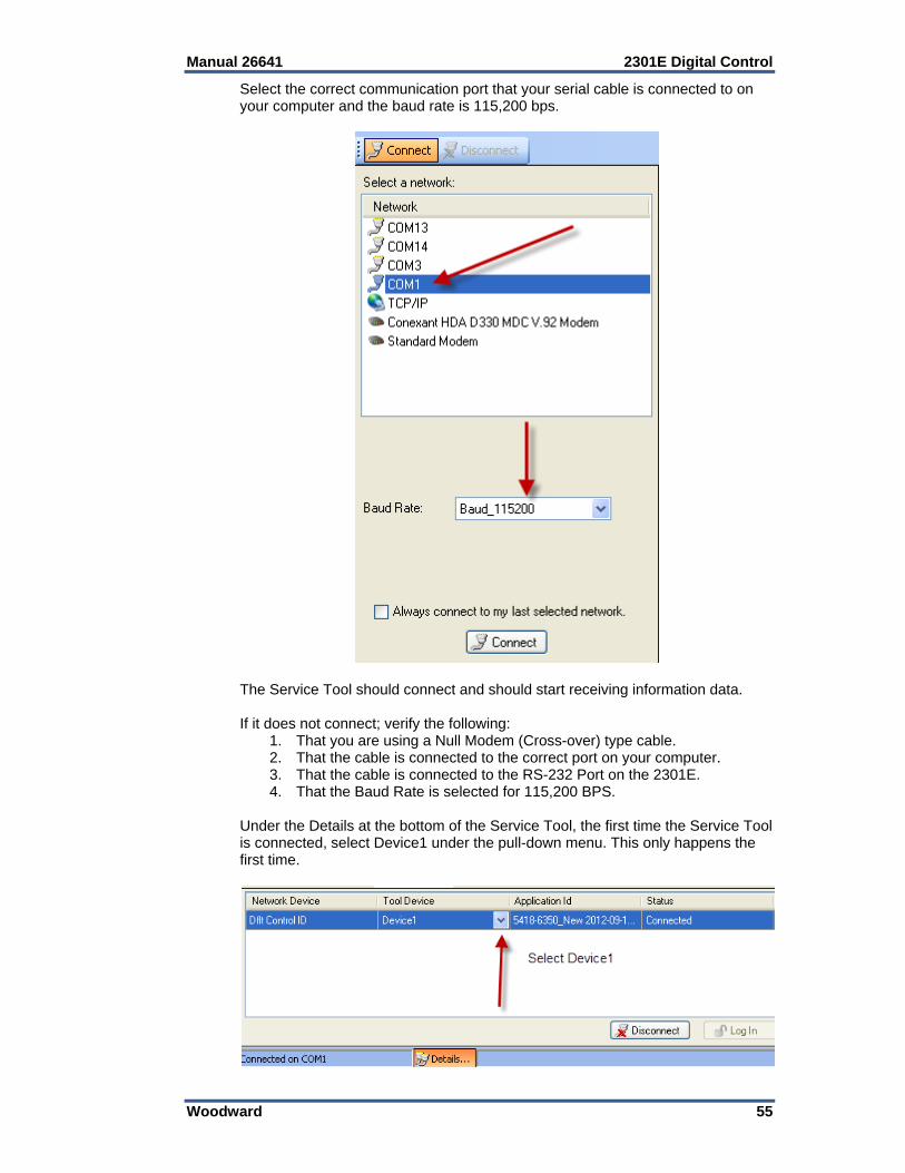
Manual 26641 2301E Digital Control
Woodward 55
Select the correct communication port that your serial cable is connected to on your computer and the baud rate is 115,200 bps.
The Service Tool should connect and should start receiving information data. If it does not connect; verify the following:
1. That you are using a Null Modem (Cross-over) type cable. 2. That the cable is connected to the correct port on your computer. 3. That the cable is connected to the RS-232 Port on the 2301E. 4. That the Baud Rate is selected for 115,200 BPS.
Under the Details at the bottom of the Service Tool, the first time the Service Tool is connected, select Device1 under the pull-down menu. This only happens the first time.
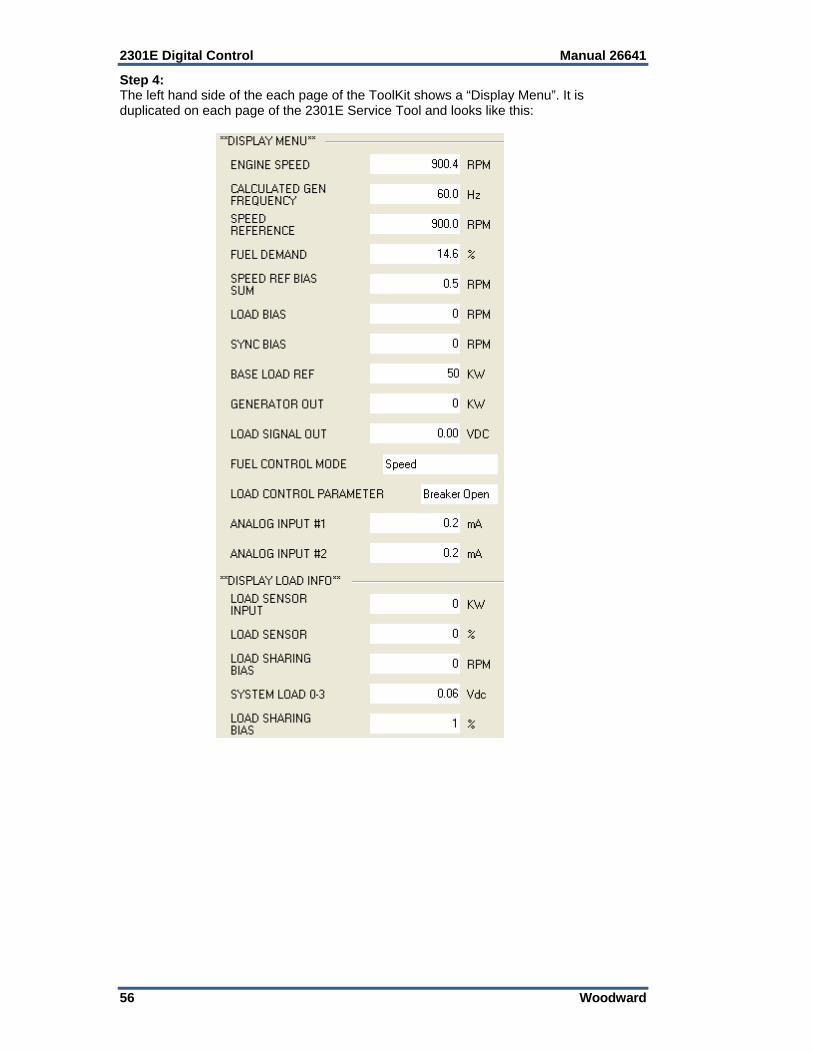
2301E Digital Control Manual 26641
56 Woodward
Step 4: The left hand side of the each page of the ToolKit shows a “Display Menu”. It is duplicated on each page of the 2301E Service Tool and looks like this:
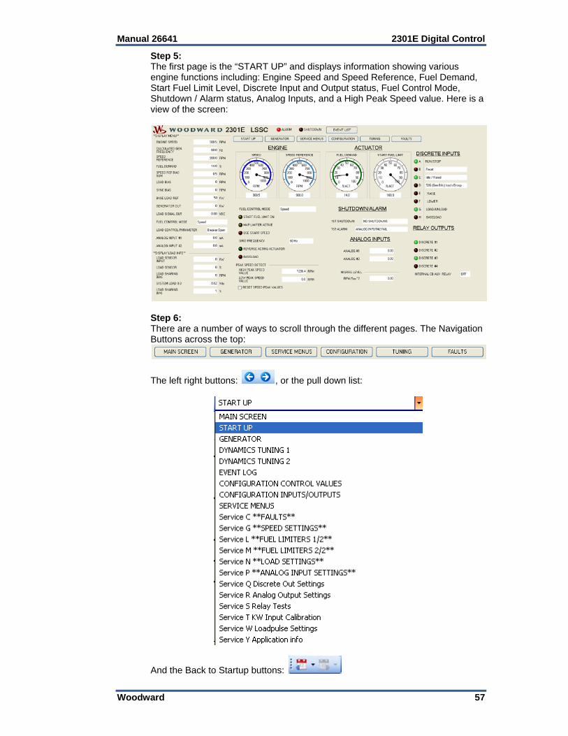
Manual 26641 2301E Digital Control
Woodward 57
Step 5: The first page is the “START UP” and displays information showing various engine functions including: Engine Speed and Speed Reference, Fuel Demand, Start Fuel Limit Level, Discrete Input and Output status, Fuel Control Mode, Shutdown / Alarm status, Analog Inputs, and a High Peak Speed value. Here is a view of the screen:
Step 6: There are a number of ways to scroll through the different pages. The Navigation Buttons across the top:
The left right buttons: , or the pull down list:
And the Back to Startup buttons:
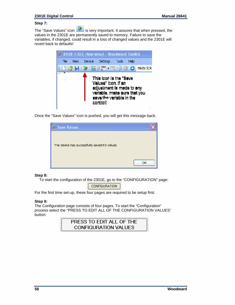
2301E Digital Control Manual 26641
58 Woodward
Step 7:
The “Save Values” icon is very important. It assures that when pressed, the values in the 2301E are permanently saved to memory. Failure to save the variables, if changed, could result in a loss of changed values and the 2301E will revert back to defaults!
Once the “Save Values” icon is pushed, you will get this message back:
Step 8:
To start the configuration of the 2301E, go to the “CONFIGURATION” page:
For the first time set-up, these four pages are required to be setup first. Step 9: The Configuration page consists of four pages. To start the “Configuration” process select the “PRESS TO EDIT ALL OF THE CONFIGURATION VALUES” button:

Manual 26641 2301E Digital Control
Woodward 59
Step 10: This will open up a new page called “Offline Settings Editor” and will read the settings or variables from the control. NOTE: Changing and applying and changes on the “Offline Settings Editor” pages will cause an I/O Lock in the control while sending new variables. This could cause the engine to shutdown or other adverse conditions. Before selecting “Apply”, make sure that the engine is secure and shutdown. Please set and understand each variable carefully, as it could have affect the engines performance. The pull-down menu will let you view and change four pages of configuration:
Apply the changes and the changes will be written to the control. Select “Cancel” to get out of the Configuration Mode. Step 11: Once the Configuration is done, select the Service Menu’s button. Select each of the Service Menu’ and continue through each one until done. Note: The Service Menu variables can be adjusted while the engine is running! Please be careful and understand the settings before making an adjustment! Refer to the manual for an explanation of each variable.
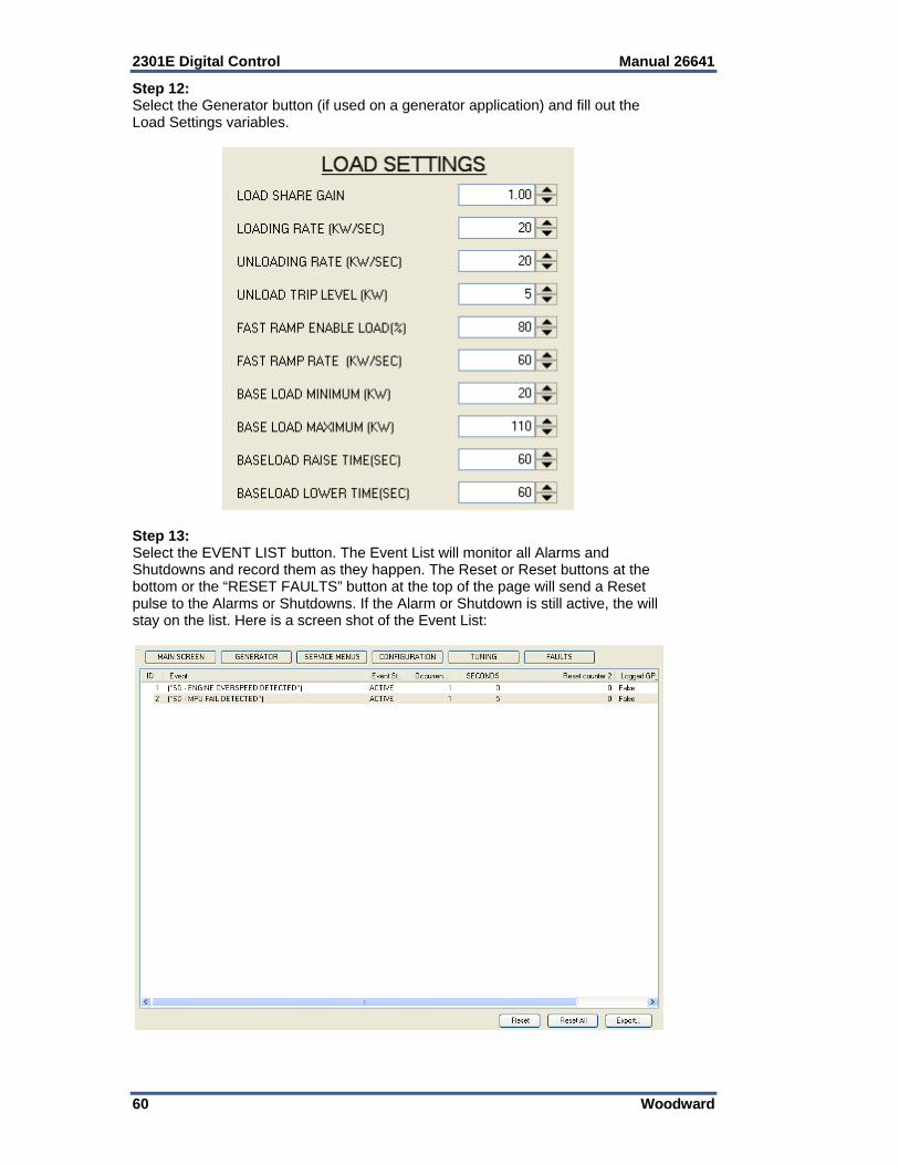
2301E Digital Control Manual 26641
60 Woodward
Step 12: Select the Generator button (if used on a generator application) and fill out the Load Settings variables.
Step 13: Select the EVENT LIST button. The Event List will monitor all Alarms and Shutdowns and record them as they happen. The Reset or Reset buttons at the bottom or the “RESET FAULTS” button at the top of the page will send a Reset pulse to the Alarms or Shutdowns. If the Alarm or Shutdown is still active, the will stay on the list. Here is a screen shot of the Event List:
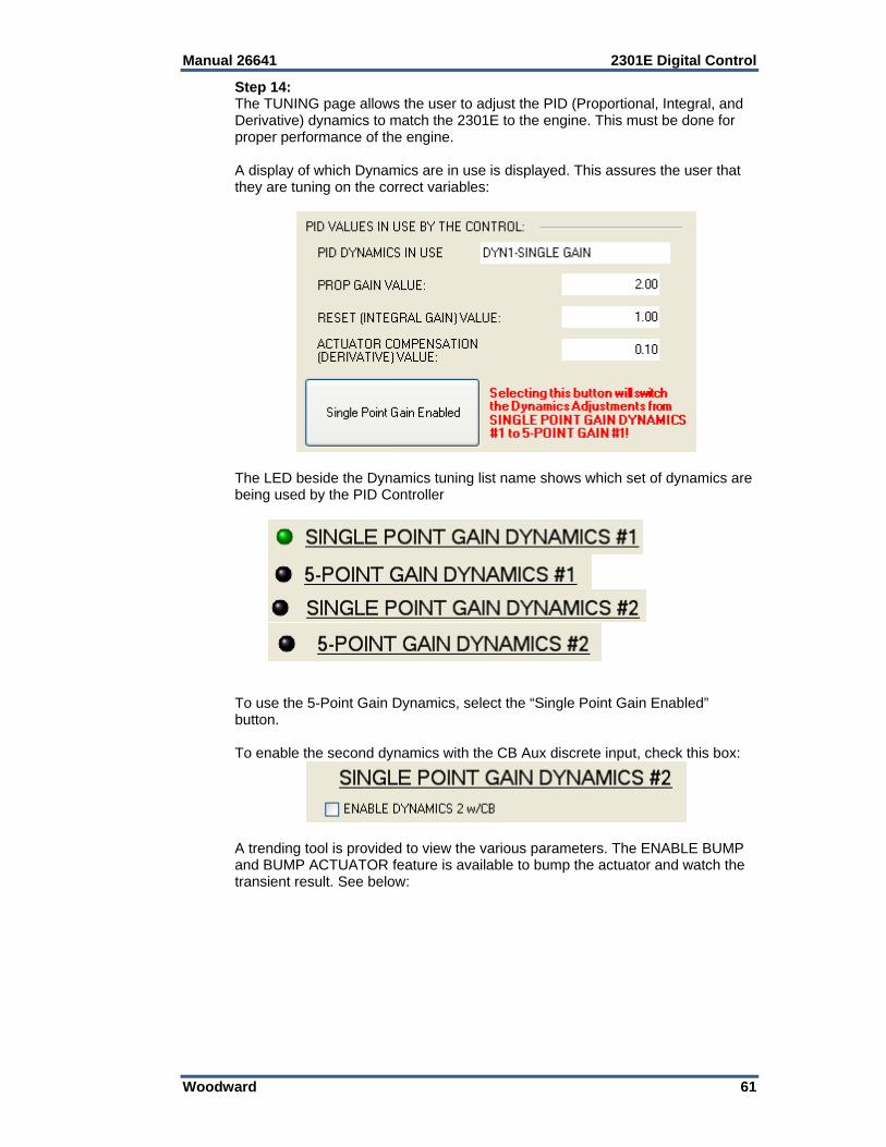
Manual 26641 2301E Digital Control
Woodward 61
Step 14: The TUNING page allows the user to adjust the PID (Proportional, Integral, and Derivative) dynamics to match the 2301E to the engine. This must be done for proper performance of the engine. A display of which Dynamics are in use is displayed. This assures the user that they are tuning on the correct variables:
The LED beside the Dynamics tuning list name shows which set of dynamics are being used by the PID Controller
To use the 5-Point Gain Dynamics, select the “Single Point Gain Enabled” button. To enable the second dynamics with the CB Aux discrete input, check this box:
A trending tool is provided to view the various parameters. The ENABLE BUMP and BUMP ACTUATOR feature is available to bump the actuator and watch the transient result. See below:
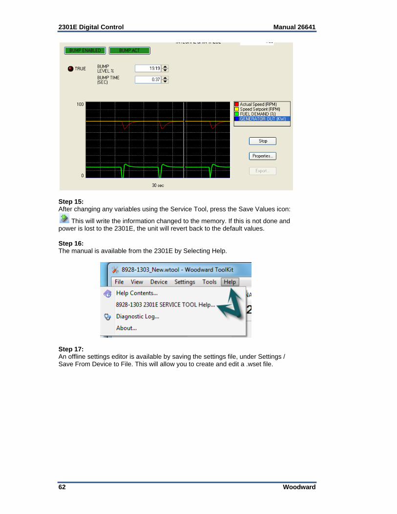
2301E Digital Control Manual 26641
62 Woodward
Step 15: After changing any variables using the Service Tool, press the Save Values icon:
This will write the information changed to the memory. If this is not done and power is lost to the 2301E, the unit will revert back to the default values. Step 16: The manual is available from the 2301E by Selecting Help.
Step 17: An offline settings editor is available by saving the settings file, under Settings / Save From Device to File. This will allow you to create and edit a .wset file.
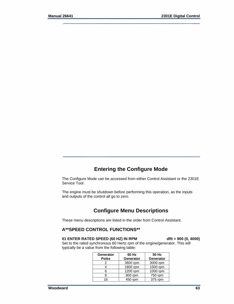
Manual 26641 2301E Digital Control
Woodward 63
Entering the Configure Mode The Configure Mode can be accessed from either Control Assistant or the 2301E Service Tool. The engine must be shutdown before performing this operation, as the inputs and outputs of the control all go to zero.
Configure Menu Descriptions These menu descriptions are listed in the order from Control Assistant. A**SPEED CONTROL FUNCTIONS** 01 ENTER RATED SPEED (60 HZ) IN RPM dflt = 900 (0, 4000) Set to the rated synchronous 60 Hertz rpm of the engine/generator. This will typically be a value from the following table:
Generator Poles
60 Hz Generator
50 Hz Generator
2 3600 rpm 3000 rpm 4 1800 rpm 1500 rpm 6 1200 rpm 1000 rpm 8 900 rpm 750 rpm
16 450 rpm 375 rpm

2301E Digital Control Manual 26641
64 Woodward
This value is used to set the 2301E speed sensor hardware to software conversion. The rated speed can be varied in Service for testing. If a rated speed other than values listed here is entered, the calculated generator frequency shown in **DISPLAY MENU** may not be correct. It is also use to set the range of the analog meters used in the 2301E Service Tool ToolKit. 02 ENTER RATED SPEED (50 HZ) in RPM dflt = 750 (0, 4000) Set to the rated synchronous 50 Hz rpm of the engine/generator (if used). The 2301E has the capability to switch between 60 Hertz operation and 50 Hertz operation for use with rental generators that require both frequencies. A Discrete Input can be configured to switch between the 50 and 60 Hertz. Note: The engine must be stopped to enable the speed to switch between the two speeds. 03 USE START SPEED dflt = FALSE (TRUE, FALSE) Set to TRUE to enable a tunable Start Speed Reference. Set to FALSE to disable the Start Speed Reference. This is typically only used on gas engines to allow speed control below idle speed and to allow acceleration to the Start Fuel Limiter without over-fueling. 04 ENABLE 5 SLOPE GAIN MAP dflt = FALSE (TRUE, FALSE) Set to TRUE to permit the use of a 5-gain curve for setting the control gain as a function of engine load. If “Use 2nd Dynamics” is also set TRUE, the use of a second 5-gain curve is activated. These two curves each provide 5 tunable gain settings at 5 tunable load-dependent breakpoints. If ‘Enable 5 Slope Gain Map’ is set FALSE only a single gain value is used as the dynamic adjustment. 05 SEL GAIN FUNCTION dflt = 1 (1, 3) Set this value for the appropriate function: o Set to “1” to make the slope breakpoints dependent on percent engine fuel
demand (Actuator %). This is the typical value. o Set to “2” to select the 5-slope gain map load axis to be based on percent
generator load (%). o Set to 3 for non-generator applications and where the dynamic slope gain
map should be dependent on the engine speed. 06 DISPLAY GAIN FUNCTION (monitor) This menu item displays the gain value selected in the previous menu: Actuator %, Load % or Engine Speed. 07 ENABLE IDLE DROOP dflt = FALSE (TRUE, FALSE) Idle Droop is used when an engine is unloaded quickly or is operated at a very low idle speed. Idle Droop is based on the controls output current. When the output actuator current drops below the “Idle Breakpoint” setting or goes to minimum fuel during rapid deceleration, the Idle Droop will increase the speed reference to allow the engine to come under control quicker, and reduces speed undershoot. This is typically used for marine or variable-speed applications. 08 OVERSPEED SETTING (RPM) dflt = 1035.00 (0.00, 4000) Set this for the maximum speed that the engine will see, typically 115% of rated speed. The 2301E initiates a shutdown when the engine speed reaches this level. 09 RST TO RATED AT CB CLOSE dflt = TRUE (TRUE, FALSE) This value when set to True will reset the speed bias to rated, after the circuit breaker is closed. If set to False, the speed could have a small error in it due to the speed bias.
Manual 26641 2301E Digital Control
Woodward 65
10 RST TO RATED INSTANT dflt = TRUE (TRUE, FALSE) This value when set to True will reset the speed bias to rated instantly, after the circuit breaker is closed. If set to False, the ramp rate to rated is slower. 11 ENABLE AUTO IDLE/RATED dflt = FALSE (TRUE, FALSE) An automatic idle to rated switch which activates rated after idle is reached and a certain time has expired. Tunable in service mode. 12 REMOTE SPD LOCK IN LAST dflt = FALSE (TRUE, FALSE) This value when set to True will lock in the last value of remote speed, if the analog input drops below or raises above the low threshold for that input type. The value will also lock if the communications fails, if using Modbus commands. An alarm will trigger, if activated. A Reset is required to reset the failed input. When this value is set to False, the speed will ramp down to the Lower Speed Limit on the event of a failed analog input. 13 REMOTE LOAD LOCK IN LAST dflt = FALSE (TRUE, FALSE) This value when set to True will lock in the last value of remote load, if the analog input drops below or raises above the low threshold for that input type. The value will also lock if the communications fails, if using Modbus commands. An alarm will trigger, if activated. A Reset is required to reset the failed input. When this value is set to False, the load will ramp down to the Baseload Minimum setting on the event of a failed analog input. 14 RESET RATED REF ON SD? dflt = TRUE (TRUE, FALSE) This value when set to True will instantly reset the speed reference back to the Rated Speed Reference on an engine shutdown. B**ENG—GEN CNTRL FUNCTIONS** 01 ENTER NUM OF GEAR TEETH dflt = 60 (8, 500) This is the number of teeth or holes of the gear or flywheel that the speed sensor is on. If the gear is on the cam shaft or other drive not turning at the prime mover speed, the number of teeth needs to be adjusted to compensate. EXAMPLE: If the gear is rotating at one-half the engine speed enter one-half the number of actual teeth.
The maximum input frequency that can be measured by the speed sensing circuit is 25 000 Hz. Therefore to allow for transient conditions, the (Number of Teeth x Rated rpm) / 60 should be less than 19 000.
The number of gear teeth is used by the control to convert pulses from the speed-sensing device to engine rpm. To prevent possible serious injury from an overspeeding engine, make sure the control is properly programmed to convert the gear-tooth count into engine rpm. Improper conversion could cause engine overspeed.
02 SPD SENSE TYPE (1, 3, 4, 5) dflt = 1 (1, 3, 4, 5)
This input determines the speed calculation where: 1. Speed Sensor Function 1 is used for medium and high speed engines. The
speed is sensed once every 1/16th of a full engine revolution and averaged with the previous 15 samples. There are 16 speed samples in the average.
2. Speed Sensor Functions 2 is not used. Do not use this value!
2301E Digital Control Manual 26641
66 Woodward
3. Speed Sensor Function 3. The speed period is sampled once every 1/SAMPLES of a full engine revolution. The last SAMPLES are averaged to determine the speed. For example, if SAMPLES = 10, then the speed period is sampled every 1/10th of an engine revolution. The speed is the average of the last 10 samples; therefore the speed is the average of the last 10 samples taken during the last engine revolution. The samples are adjusted by entering the Number of Cylinders in the Configure menu.
4. Speed Sensor Function 4. This function is specifically designed to give readings at low speeds without the delay associated with other types of speed sensing blocks. The speed period is sampled on every gear tooth. The speed is determined from the average of the last 2 gear tooth samples. Note: Speed Sensor Type 4 should only be used in applications where the gear tooth frequencies are below 1000 Hz. Higher frequencies may cause control problems.
5. Speed Sensor Function 5 is specifically designed with an adaptive rotational speed sensing filter. This filter will give stable speed sensor readings for:
o Low and medium engine speeds. (<1600 MPU frequency) o Engine torsional frequencies caused by engine firing frequencies, or
various engine loads. o Noisy MPU signals caused by run-out in the gear, irregular shaped
gear teeth or irregular shaped holes in the flywheel. Speed Function 5 is also used with the following menu items:
o Configure Menu B**ENG—GEN CNTRL FUNCTIONS** 03 ENTER NUMB OF CYLINDERS.
o Service Menu X**ADAPTIVE FILTER SET** 01 ADAPTIVE FILTER ENABLE. (This value works well for most applications)
o Service Menu X**ADAPTIVE FILTER SET** 02 ADAPTIVE FILTER GAIN. (This value works well for most applications)
03 ENTER NUMB OF CYLINDERS dflt = 8 (1.0, 24.0) This is the number of cylinders the engine has, and is also the number of speed samples the control will take during each engine revolution. This is only used with Speed Sensor Function Type 3. 04 ENTER FAILED SPD SENSE % dflt = 5 (2.0, 50.0) This should be set to a percentage of rated prime mover speed that will verify a valid MPU signal exists while the prime mover is starting. (Default is 5% of rated.) 05 MPU ALARM ARM TIME dflt = 10 (0.0, 120.0) This value is the time delay, in seconds, to wait before latching the MPU failure alarm and shutdown functions once a valid MPU signal is detected. Opening the “RUN” contact resets the latch block to prevent MPU failure alarm and shutdown conditions from occurring with normal stops. 06 ENTER RATED/MAX LOAD (KW) dflt = 500 (10, 30000) This is the maximum generator load (in kilowatts). 07 2 CYCLE OR 4 CYCLE? dflt = 1 (1, 2) This value is the number of revolutions per engine cycle. Set this value to 1 for a two-cycle engine, and 2 for a four-cycle engine. 08 MAX ENGINE SPEED PERCENT dflt = 120 (30, 400) This value is the maximum speed percentage that engine will run from the rated speed percentage. This value is typically used for variable speed applications. EXAMPLE: With this value raised, the engine speed can be controlled from 900 to 3600 rpm.
Manual 26641 2301E Digital Control
Woodward 67
C**DISCRETE IN OPTIONS** 01 SEL DI B FUNCTION (1-9) dflt = 3 (1, 9) Used to select the function for Digital Input #2 (B) terminal 35. 1 Not used 2 Failed speed override 3 Reset (default) 4 Select 2nd dynamics 5 Shutdown external 6 Idle/rated switch 7 Generator Breaker (52G) Isoch 8 Derate KW Load Reference 9 50/60 Hertz Operation 02 DISPLAY DI B FUNCTION (monitor) Shows the function of input B. 03 SEL DI C FUNCTION (1-9) dflt = 6 (1, 9) Used to select the function for digital input 3 (C) terminal 36. 1 Not used 2 Failed speed override 3 Reset 4 Select 2nd dynamics 5 Shutdown external 6 Idle/rated switch (default) 7 Generator Breaker (52G) Isoch 8 Derate KW Load Reference 9 50/60 Hertz Operation 04 DISPLAY DI C FUNCTION (monitor) Shows the function of input C. 05 SEL DI D FUNCTION (1-9) dflt = 7 (1, 9) Used to select the function for digital input 4 (D) terminal 37. 1 Not used 2 Failed speed override 3 Reset 4 Select 2nd dynamics 5 Shutdown external 6 Idle/rated switch 7 Generator Breaker (52G) Isoch (default) 8 Derate KW Load Reference 9 50/60 Hertz Operation 06 DISPLAY DI D FUNCTION (monitor) Shows the function of input D. 07 ENABLE R/L WHEN LS dflt=FALSE (FALSE, TRUE) Set to TRUE will enable the Raise Speed/Load and Lower Speed/Load discrete inputs while in isochronous load sharing. Typically this is not used as the control will balance the loads automatically. This value can be used to adjust the speed of a generator bus, so that it can be synchronized to a utility bus. 08 RSE/LWR STOP IDL/RTD RMP dflt=TRUE (FALSE, TRUE) If set TRUE the raise and lower inputs are active during ramping from idle to rated. During the ramp from idle to rated, if either the Raise or Lower contact is toggled, the ramp will immediately stop. If set FALSE the raise and lower inputs are disabled until rated speed has reached.
2301E Digital Control Manual 26641
68 Woodward
D**DISCRETE OUT OPTIONS** The 2301E has four discrete output driver channels. Terminals 44, 45, 46, and 47 are configurable and can be programmed to perform one of the following functions. Any of the four relays can also be programmed to function as a level switch. When programmed as a level switch the relay changes state when the selected parameter reaches the programmed level (energizes when value is higher the programmed level). Level Switch set up is in Service Menu Q**Discrete Out Settings**. 01 IS SHUTDOWN RELAY NC? dflt = TRUE (FALSE, TRUE) This option sets the logic of the Shutdown Relay. Set to TRUE if the shutdown relay output is normally closed. Set to FALSE if the shutdown relay output is normally open. 02 IS ALARM RELAY NC? dflt = TRUE (FALSE, TRUE) This option sets the logic of the alarm relay. Set to TRUE if the alarm relay output is normally closed. Set to FALSE if the alarm relay output is normally open. 03 RELAY 1 ENERGIZES (1-12) dflt = 2 (1, 12) Select one of the following parameters for discrete output at terminal 44. 1 = NOT USED 2 = SHUTDOWN 3 = ALARM 4 = ELEC. OVERSPEED TRIP TEST 5 = START FUEL LIMITER IN CONTROL 6 = SPEED PID IN CONTROL 7 = CIRCUIT BREAKER OPEN COMMAND 8 = OVERLOAD CONTACT 9 = LEVEL SWITCH 10 = CPU FAILURE 11 = FORCE OUTPUTS 12= IN REMOTE SPEED CONTROL Parameters 11 thru 14 are only applicable for the 2301E with Modbus (see Chapter 8, Communications): 12 = MODBUS RELAY #1 13 = MODBUS RELAY #2 14 = MODBUS RELAY #3 15 = MODBUS RELAY #4 04 RELAY 1 SELECTED FOR (monitor) Displays the relay function for terminal 44. 05 RELAY 2 ENERGIZES (1-12) dflt = 3 (1, 12) Select one of the following parameters for discrete output at terminal 45 (same as parameters in 03 RELAY 1 ENERGIZES). 06 RELAY 2 SELECTED FOR (monitor) Displays the relay function for terminal 45. 07 RELAY 3 ENERGIZES (1-12) dflt = 9 (1, 12) Select one of the following parameters for discrete output at terminal 46 (same as parameters in 03 RELAY 1 ENERGIZES). 08 RELAY 3 SELECTED FOR (monitor) Displays the relay function for terminal 46.
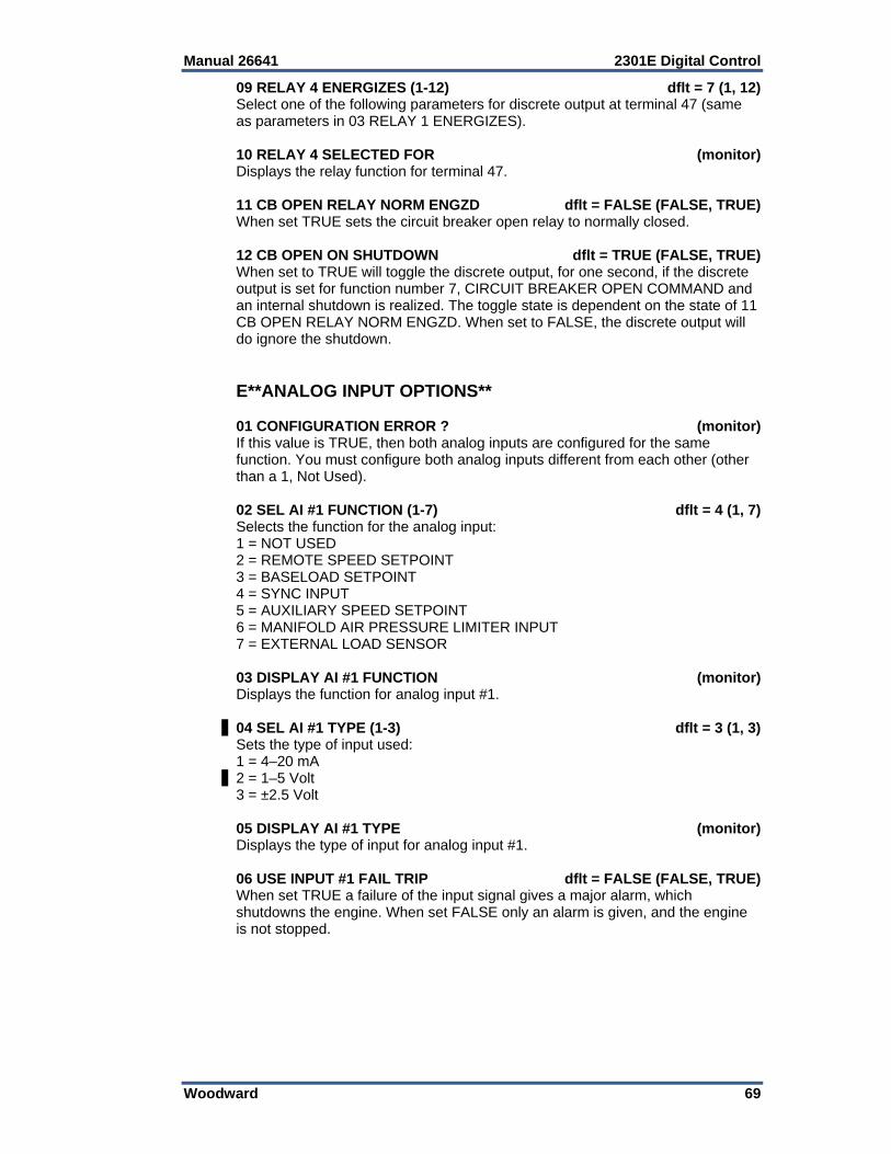
Manual 26641 2301E Digital Control
Woodward 69
09 RELAY 4 ENERGIZES (1-12) dflt = 7 (1, 12) Select one of the following parameters for discrete output at terminal 47 (same as parameters in 03 RELAY 1 ENERGIZES). 10 RELAY 4 SELECTED FOR (monitor) Displays the relay function for terminal 47. 11 CB OPEN RELAY NORM ENGZD dflt = FALSE (FALSE, TRUE) When set TRUE sets the circuit breaker open relay to normally closed. 12 CB OPEN ON SHUTDOWN dflt = TRUE (FALSE, TRUE) When set to TRUE will toggle the discrete output, for one second, if the discrete output is set for function number 7, CIRCUIT BREAKER OPEN COMMAND and an internal shutdown is realized. The toggle state is dependent on the state of 11 CB OPEN RELAY NORM ENGZD. When set to FALSE, the discrete output will do ignore the shutdown. E**ANALOG INPUT OPTIONS** 01 CONFIGURATION ERROR ? (monitor) If this value is TRUE, then both analog inputs are configured for the same function. You must configure both analog inputs different from each other (other than a 1, Not Used). 02 SEL AI #1 FUNCTION (1-7) dflt = 4 (1, 7) Selects the function for the analog input: 1 = NOT USED 2 = REMOTE SPEED SETPOINT 3 = BASELOAD SETPOINT 4 = SYNC INPUT 5 = AUXILIARY SPEED SETPOINT 6 = MANIFOLD AIR PRESSURE LIMITER INPUT 7 = EXTERNAL LOAD SENSOR 03 DISPLAY AI #1 FUNCTION (monitor) Displays the function for analog input #1. 04 SEL AI #1 TYPE (1-3) dflt = 3 (1, 3) Sets the type of input used: 1 = 4–20 mA 2 = 1–5 Volt 3 = ±2.5 Volt 05 DISPLAY AI #1 TYPE (monitor) Displays the type of input for analog input #1. 06 USE INPUT #1 FAIL TRIP dflt = FALSE (FALSE, TRUE) When set TRUE a failure of the input signal gives a major alarm, which shutdowns the engine. When set FALSE only an alarm is given, and the engine is not stopped.
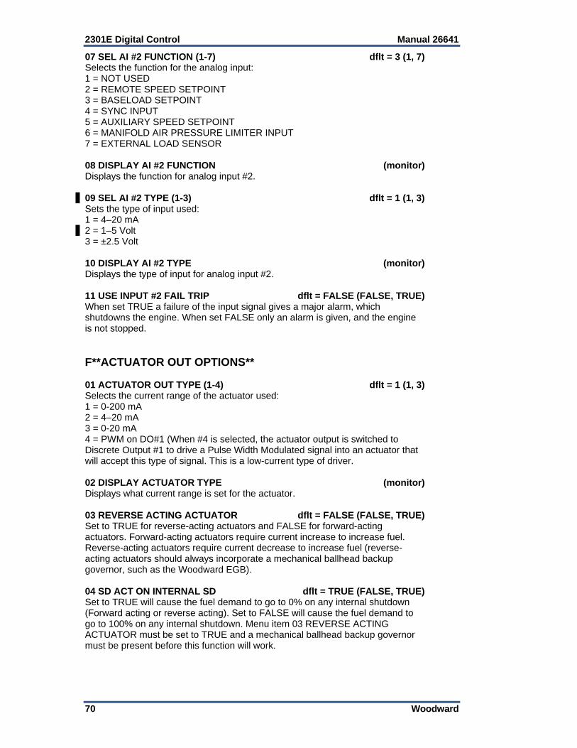
2301E Digital Control Manual 26641
70 Woodward
07 SEL AI #2 FUNCTION (1-7) dflt = 3 (1, 7) Selects the function for the analog input: 1 = NOT USED 2 = REMOTE SPEED SETPOINT 3 = BASELOAD SETPOINT 4 = SYNC INPUT 5 = AUXILIARY SPEED SETPOINT 6 = MANIFOLD AIR PRESSURE LIMITER INPUT 7 = EXTERNAL LOAD SENSOR 08 DISPLAY AI #2 FUNCTION (monitor) Displays the function for analog input #2. 09 SEL AI #2 TYPE (1-3) dflt = 1 (1, 3) Sets the type of input used: 1 = 4–20 mA 2 = 1–5 Volt 3 = ±2.5 Volt 10 DISPLAY AI #2 TYPE (monitor) Displays the type of input for analog input #2. 11 USE INPUT #2 FAIL TRIP dflt = FALSE (FALSE, TRUE) When set TRUE a failure of the input signal gives a major alarm, which shutdowns the engine. When set FALSE only an alarm is given, and the engine is not stopped. F**ACTUATOR OUT OPTIONS** 01 ACTUATOR OUT TYPE (1-4) dflt = 1 (1, 3) Selects the current range of the actuator used: 1 = 0-200 mA 2 = 4–20 mA 3 = 0-20 mA 4 = PWM on DO#1 (When #4 is selected, the actuator output is switched to Discrete Output #1 to drive a Pulse Width Modulated signal into an actuator that will accept this type of signal. This is a low-current type of driver. 02 DISPLAY ACTUATOR TYPE (monitor) Displays what current range is set for the actuator. 03 REVERSE ACTING ACTUATOR dflt = FALSE (FALSE, TRUE) Set to TRUE for reverse-acting actuators and FALSE for forward-acting actuators. Forward-acting actuators require current increase to increase fuel. Reverse-acting actuators require current decrease to increase fuel (reverse-acting actuators should always incorporate a mechanical ballhead backup governor, such as the Woodward EGB). 04 SD ACT ON INTERNAL SD dflt = TRUE (FALSE, TRUE) Set to TRUE will cause the fuel demand to go to 0% on any internal shutdown (Forward acting or reverse acting). Set to FALSE will cause the fuel demand to go to 100% on any internal shutdown. Menu item 03 REVERSE ACTING ACTUATOR must be set to TRUE and a mechanical ballhead backup governor must be present before this function will work.

Manual 26641 2301E Digital Control
Woodward 71
05 PWM FREQUENCY dflt = 500.00 300.0, 2000.0) Sets the Duty Cycle Pulse Width Modulated output frequency of Discrete Output #1, when 01 ACTUATOR OUT TYPE (1-4) is selected to #4, PWM Output. 06 DUTY CYCLE AT 0% dflt = 90.00 (-10.00, 110.00) Sets the minimum Duty Cycle output of Discrete Output #1, when 01 ACTUATOR OUT TYPE (1-4) is selected to #4. 07 DUTY CYCLE AT 100% dflt = 90.00 (-10.00, 110.00) Sets the maximum Duty Cycle output of Discrete Output #1, when 01 ACTUATOR OUT TYPE (1-4) is selected to #4. 08 DUTY CYCLE MIN LIMIT dflt = 10.00 (0.00, 100.00) Sets the minimum Duty Cycle output limit of Discrete Output #1, when 01 ACTUATOR OUT TYPE (1-4) is selected to #4, PWM Output. 09 DUTY CYCLE MAX LIMIT dflt = 90.00 (0.00, 100.00) Sets the maximum Duty Cycle output limit of Discrete Output #1, when 01 ACTUATOR OUT TYPE (1-4) is selected to #4. G**DISCRETE IN ACTION** 01 SEL DI “A” ACTION dflt = FALSE (FALSE, TRUE) Selects the logic function of the discrete input “A”, terminal 34. When this input is selected to FALSE, the input will be OFF or De-energized when the contact is open and ON or Energized when the contact is closed. When this input is selected to TRUE, the input will be ON or Energized when the contact is open and OFF or De-energized when the contact is closed. 01 SEL DI “B” ACTION dflt = FALSE (FALSE, TRUE) Selects the logic function of the discrete input “B”, terminal 35. When this input is selected to FALSE, the input will be OFF or De-energized when the contact is open and ON or Energized when the contact is closed. When this input is selected to TRUE, the input will be ON or Energized when the contact is open and OFF or De-energized when the contact is closed. 01 SEL DI “C” ACTION dflt = FALSE (FALSE, TRUE) Selects the logic function of the discrete input “C”, terminal 36. When this input is selected to FALSE, the input will be OFF or De-energized when the contact is open and ON or Energized when the contact is closed. When this input is selected to TRUE, the input will be ON or Energized when the contact is open and OFF or De-energized when the contact is closed. 01 SEL DI “D” ACTION dflt = FALSE (FALSE, TRUE) Selects the logic function of the discrete input “D”, terminal 37. When this input is selected to FALSE, the input will be OFF or De-energized when the contact is open and ON or Energized when the contact is closed. When this input is selected to TRUE, the input will be ON or Energized when the contact is open and OFF or De-energized when the contact is closed. 01 SEL DI “E” ACTION dflt = FALSE (FALSE, TRUE) Selects the logic function of the discrete input “E”, terminal 38. When this input is selected to FALSE, the input will be OFF or De-energized when the contact is open and ON or Energized when the contact is closed. When this input is selected to TRUE, the input will be ON or Energized when the contact is open and OFF or De-energized when the contact is closed.
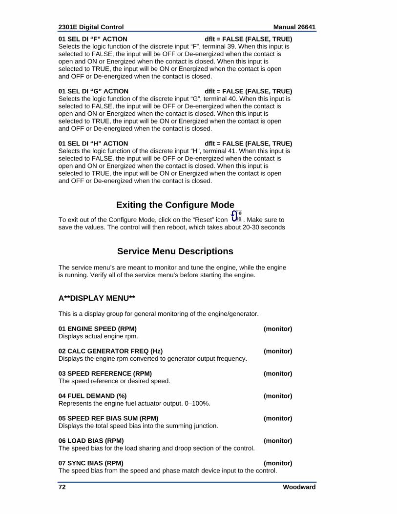
2301E Digital Control Manual 26641
72 Woodward
01 SEL DI “F” ACTION dflt = FALSE (FALSE, TRUE) Selects the logic function of the discrete input “F”, terminal 39. When this input is selected to FALSE, the input will be OFF or De-energized when the contact is open and ON or Energized when the contact is closed. When this input is selected to TRUE, the input will be ON or Energized when the contact is open and OFF or De-energized when the contact is closed. 01 SEL DI “G” ACTION dflt = FALSE (FALSE, TRUE) Selects the logic function of the discrete input “G”, terminal 40. When this input is selected to FALSE, the input will be OFF or De-energized when the contact is open and ON or Energized when the contact is closed. When this input is selected to TRUE, the input will be ON or Energized when the contact is open and OFF or De-energized when the contact is closed. 01 SEL DI “H” ACTION dflt = FALSE (FALSE, TRUE) Selects the logic function of the discrete input “H”, terminal 41. When this input is selected to FALSE, the input will be OFF or De-energized when the contact is open and ON or Energized when the contact is closed. When this input is selected to TRUE, the input will be ON or Energized when the contact is open and OFF or De-energized when the contact is closed.
Exiting the Configure Mode
To exit out of the Configure Mode, click on the “Reset” icon . Make sure to save the values. The control will then reboot, which takes about 20-30 seconds
Service Menu Descriptions The service menu’s are meant to monitor and tune the engine, while the engine is running. Verify all of the service menu’s before starting the engine. A**DISPLAY MENU** This is a display group for general monitoring of the engine/generator. 01 ENGINE SPEED (RPM) (monitor) Displays actual engine rpm. 02 CALC GENERATOR FREQ (Hz) (monitor) Displays the engine rpm converted to generator output frequency. 03 SPEED REFERENCE (RPM) (monitor) The speed reference or desired speed. 04 FUEL DEMAND (%) (monitor) Represents the engine fuel actuator output. 0–100%. 05 SPEED REF BIAS SUM (RPM) (monitor) Displays the total speed bias into the summing junction. 06 LOAD BIAS (RPM) (monitor) The speed bias for the load sharing and droop section of the control. 07 SYNC BIAS (RPM) (monitor) The speed bias from the speed and phase match device input to the control.
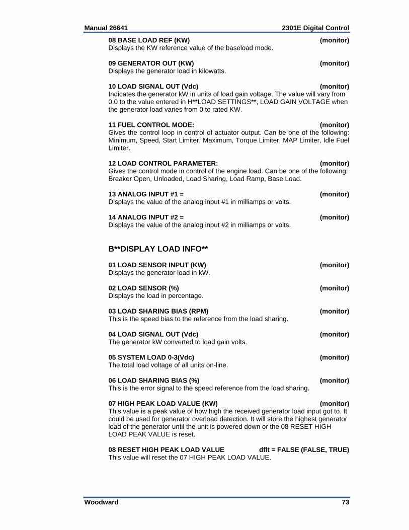
Manual 26641 2301E Digital Control
Woodward 73
08 BASE LOAD REF (KW) (monitor) Displays the KW reference value of the baseload mode. 09 GENERATOR OUT (KW) (monitor) Displays the generator load in kilowatts. 10 LOAD SIGNAL OUT (Vdc) (monitor) Indicates the generator kW in units of load gain voltage. The value will vary from 0.0 to the value entered in H**LOAD SETTINGS**, LOAD GAIN VOLTAGE when the generator load varies from 0 to rated KW. 11 FUEL CONTROL MODE: (monitor) Gives the control loop in control of actuator output. Can be one of the following: Minimum, Speed, Start Limiter, Maximum, Torque Limiter, MAP Limiter, Idle Fuel Limiter. 12 LOAD CONTROL PARAMETER: (monitor) Gives the control mode in control of the engine load. Can be one of the following: Breaker Open, Unloaded, Load Sharing, Load Ramp, Base Load. 13 ANALOG INPUT #1 = (monitor) Displays the value of the analog input #1 in milliamps or volts. 14 ANALOG INPUT #2 = (monitor) Displays the value of the analog input #2 in milliamps or volts. B**DISPLAY LOAD INFO** 01 LOAD SENSOR INPUT (KW) (monitor) Displays the generator load in kW. 02 LOAD SENSOR (%) (monitor) Displays the load in percentage. 03 LOAD SHARING BIAS (RPM) (monitor) This is the speed bias to the reference from the load sharing. 04 LOAD SIGNAL OUT (Vdc) (monitor) The generator kW converted to load gain volts. 05 SYSTEM LOAD 0-3(Vdc) (monitor) The total load voltage of all units on-line. 06 LOAD SHARING BIAS (%) (monitor) This is the error signal to the speed reference from the load sharing. 07 HIGH PEAK LOAD VALUE (KW) (monitor) This value is a peak value of how high the received generator load input got to. It could be used for generator overload detection. It will store the highest generator load of the generator until the unit is powered down or the 08 RESET HIGH LOAD PEAK VALUE is reset. 08 RESET HIGH PEAK LOAD VALUE dflt = FALSE (FALSE, TRUE) This value will reset the 07 HIGH PEAK LOAD VALUE.
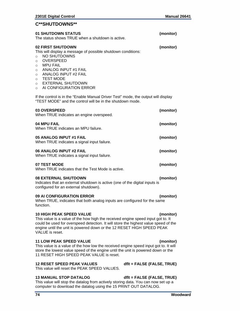
2301E Digital Control Manual 26641
74 Woodward
C**SHUTDOWNS** 01 SHUTDOWN STATUS (monitor) The status shows TRUE when a shutdown is active. 02 FIRST SHUTDOWN (monitor) This will display a message of possible shutdown conditions: o NO SHUTDOWNS o OVERSPEED o MPU FAIL o ANALOG INPUT #1 FAIL o ANALOG INPUT #2 FAIL o TEST MODE o EXTERNAL SHUTDOWN o AI CONFIGURATION ERROR If the control is in the “Enable Manual Driver Test” mode, the output will display “TEST MODE” and the control will be in the shutdown mode. 03 OVERSPEED (monitor) When TRUE indicates an engine overspeed. 04 MPU FAIL (monitor) When TRUE indicates an MPU failure. 05 ANALOG INPUT #1 FAIL (monitor) When TRUE indicates a signal input failure. 06 ANALOG INPUT #2 FAIL (monitor) When TRUE indicates a signal input failure. 07 TEST MODE (monitor) When TRUE indicates that the Test Mode is active. 08 EXTERNAL SHUTDOWN (monitor) Indicates that an external shutdown is active (one of the digital inputs is configured for an external shutdown). 09 AI CONFIGURATION ERROR (monitor) When TRUE, indicates that both analog inputs are configured for the same function. 10 HIGH PEAK SPEED VALUE (monitor) This value is a value of the how high the received engine speed input got to. It could be used for overspeed detection. It will store the highest value speed of the engine until the unit is powered down or the 12 RESET HIGH SPEED PEAK VALUE is reset. 11 LOW PEAK SPEED VALUE (monitor) This value is a value of the how low the received engine speed input got to. It will store the lowest value speed of the engine until the unit is powered down or the 11 RESET HIGH SPEED PEAK VALUE is reset. 12 RESET SPEED PEAK VALUES dflt = FALSE (FALSE, TRUE) This value will reset the PEAK SPEED VALUES. 13 MANUAL STOP DATALOG dflt = FALSE (FALSE, TRUE) This value will stop the datalog from actively storing data. You can now set up a computer to download the datalog using the 15 PRINT OUT DATALOG.
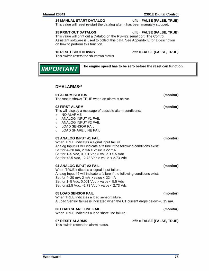
Manual 26641 2301E Digital Control
Woodward 75
14 MANUAL START DATALOG dflt = FALSE (FALSE, TRUE) This value will reset re-start the datalog after it has been manually stopped. 15 PRINT OUT DATALOG dflt = FALSE (FALSE, TRUE) This value will print out a Datalog on the RS-422 serial port. The Control Assistant software is used to collect this data. See Appendix E for a description on how to perform this function. 16 RESET SHUTDOWNS dflt = FALSE (FALSE, TRUE) This switch resets the shutdown status.
The engine speed has to be zero before the reset can function.
D**ALARMS** 01 ALARM STATUS (monitor) The status shows TRUE when an alarm is active. 02 FIRST ALARM (monitor) This will display a message of possible alarm conditions: o NO ALARMS o ANALOG INPUT #1 FAIL o ANALOG INPUT #2 FAIL o LOAD SENSOR FAIL o LOAD SHARE LINE FAIL 03 ANALOG INPUT #1 FAIL (monitor) When TRUE indicates a signal input failure. Analog Input #1 will indicate a failure if the following conditions exist: Set for 4–20 mA, 2 mA > value < 22 mA Set for 1–5 Vdc, 0.001 Vdc > value < 5.5 Vdc Set for ±2.5 Vdc, –2.73 Vdc > value < 2.73 Vdc 04 ANALOG INPUT #2 FAIL (monitor) When TRUE indicates a signal input failure. Analog Input #2 will indicate a failure if the following conditions exist: Set for 4–20 mA, 2 mA > value < 22 mA Set for 1–5 Vdc, 0.001 Vdc > value < 5.5 Vdc Set for ±2.5 Vdc, –2.73 Vdc > value < 2.73 Vdc 05 LOAD SENSOR FAIL (monitor) When TRUE indicates a load sensor failure. A Load Sensor failure is indicated when the CT current drops below –0.15 mA. 06 LOAD SHARE LINE FAIL (monitor) When TRUE indicates a load share line failure. 07 RESET ALARMS dflt = FALSE (FALSE, TRUE) This switch resets the alarm status.
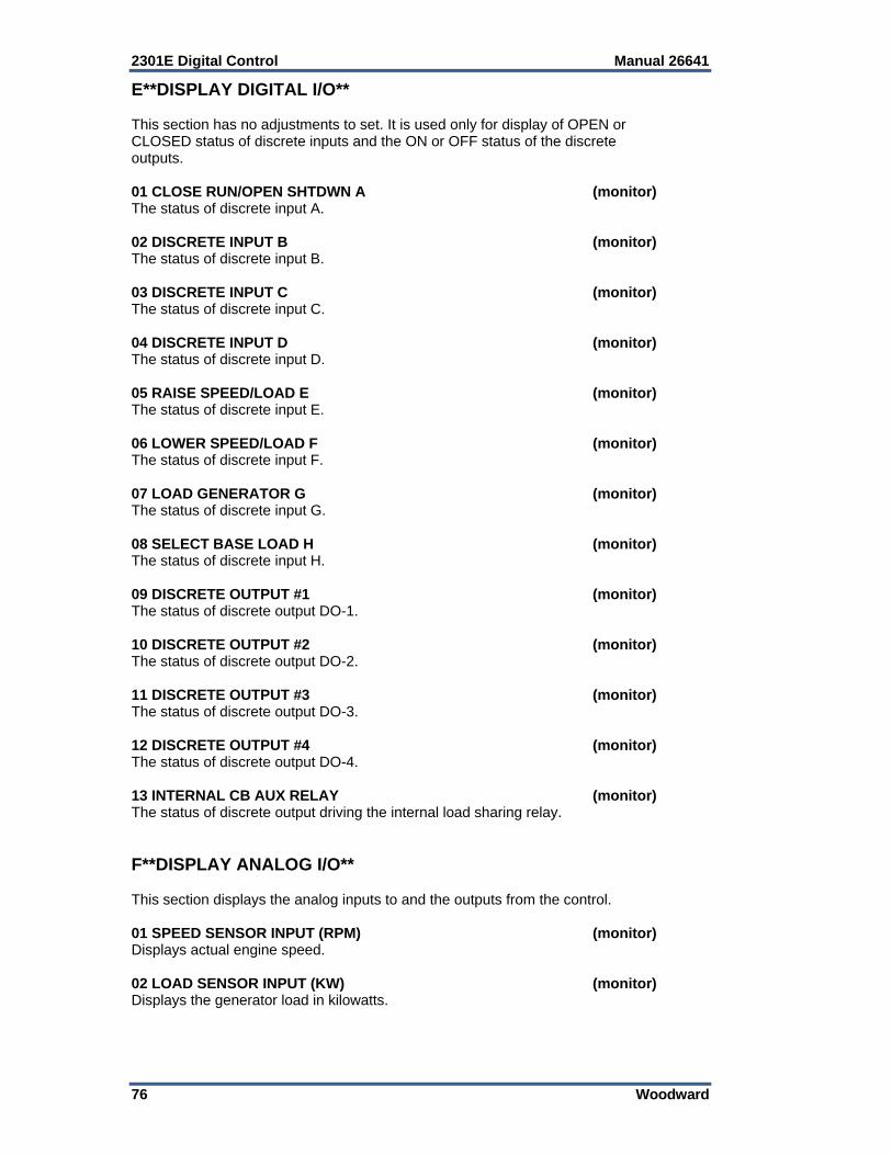
2301E Digital Control Manual 26641
76 Woodward
E**DISPLAY DIGITAL I/O** This section has no adjustments to set. It is used only for display of OPEN or CLOSED status of discrete inputs and the ON or OFF status of the discrete outputs. 01 CLOSE RUN/OPEN SHTDWN A (monitor) The status of discrete input A. 02 DISCRETE INPUT B (monitor) The status of discrete input B. 03 DISCRETE INPUT C (monitor) The status of discrete input C. 04 DISCRETE INPUT D (monitor) The status of discrete input D. 05 RAISE SPEED/LOAD E (monitor) The status of discrete input E. 06 LOWER SPEED/LOAD F (monitor) The status of discrete input F. 07 LOAD GENERATOR G (monitor) The status of discrete input G. 08 SELECT BASE LOAD H (monitor) The status of discrete input H. 09 DISCRETE OUTPUT #1 (monitor) The status of discrete output DO-1. 10 DISCRETE OUTPUT #2 (monitor) The status of discrete output DO-2. 11 DISCRETE OUTPUT #3 (monitor) The status of discrete output DO-3. 12 DISCRETE OUTPUT #4 (monitor) The status of discrete output DO-4. 13 INTERNAL CB AUX RELAY (monitor) The status of discrete output driving the internal load sharing relay. F**DISPLAY ANALOG I/O** This section displays the analog inputs to and the outputs from the control. 01 SPEED SENSOR INPUT (RPM) (monitor) Displays actual engine speed. 02 LOAD SENSOR INPUT (KW) (monitor) Displays the generator load in kilowatts.

Manual 26641 2301E Digital Control
Woodward 77
03 ANIN #1, INPUT TYPE (monitor) Displays one of the following to indicate the input range selected for input 1: 4–20 mA ± 2.5 V 1–5 V 04 ANIN #1 (UNITS) (monitor) Displays the units of the input type above (volts or mA) of the analog Input #1. 05 ANIN #2, INPUT TYPE (monitor) Displays one of the following to indicate the input range selected for input 2: 4–20 mA 1–5 V ±2.5 V 06 ANIN #2 (UNITS) (monitor) Displays the units of the input type above (volts or mA) of the analog Input #2. 07 LOAD SHARING LINES (Vdc) (monitor) Indicates the voltage present at terminals 10 and 11. 08 LOAD SHARING BIAS SIG (%) (monitor) The error signal to the speed reference from the load sharing and/or droop circuitry. 09 ACTUATOR CURRENT (mA) (monitor) The calculated actuator output current in milliamps. This calculation is based on the percent fuel demand and the actuator type/range selected. External wiring may affect the accuracy of the actual current. 10 ANALOG OUT 1 (%) (monitor) The output at terminals 16 and 17. 0% is 4 mA, 100% is 20 mA. 11 LOAD SIGNAL (Vdc) (monitor) The generator kW converted to load gain volts. G**SPEED SETTINGS** Speed settings are the parameters that affect the prime mover speed reference. 01 START SPEED (RPM) dflt = 400.00 (1.00, 2100) The initial speed reference for the speed control before starting. Start speed must be set above cranking speed and below the speed achieved with the start fuel limit setting (light-off speed). A ramp from start speed to idle or rated, whichever is selected, begins when the engine accelerates to start speed. The ramp time is the accel ramp time setting, when going to the rated speed setpoint. The ramp time is the decel ramp time setting, when going to the idle speed setpoint. 02 RAISE SPEED LIMIT (RPM) dflt = 1000.00 (0.00, 4000.00) The maximum speed reference setting when the raise switch is closed. It is normally set at the speed at which the engine operates at full load if the Droop mode is used, or at the high limit of the speed trim function.
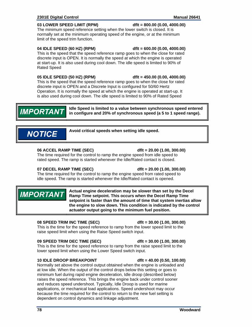
2301E Digital Control Manual 26641
78 Woodward
03 LOWER SPEED LIMIT (RPM) dflt = 800.00 (0.00, 4000.00) The minimum speed reference setting when the lower switch is closed. It is normally set at the minimum operating speed of the engine, or at the minimum limit of the speed trim function. 04 IDLE SPEED (60 HZ) (RPM) dflt = 600.00 (0.00, 4000.00) This is the speed that the speed reference ramp goes to when the close for rated discrete input is OPEN. It is normally the speed at which the engine is operated at start-up. It is also used during cool down. The idle speed is limited to 90% of Rated Speed 05 IDLE SPEED (50 HZ) (RPM) dflt = 450.00 (0.00, 4000.00) This is the speed that the speed reference ramp goes to when the close for rated discrete input is OPEN and a Discrete Input is configured for 50/60 Hertz Operation. It is normally the speed at which the engine is operated at start-up. It is also used during cool down. The idle speed is limited to 90% of Rated Speed
Idle Speed is limited to a value between synchronous speed entered in configure and 20% of synchronous speed (a 5 to 1 speed range).
Avoid critical speeds when setting idle speed.
06 ACCEL RAMP TIME (SEC) dflt = 20.00 (1.00, 300.00) The time required for the control to ramp the engine speed from idle speed to rated speed. The ramp is started whenever the Idle/Rated contact is closed. 07 DECEL RAMP TIME (SEC) dflt = 20.00 (1.00, 300.00) The time required for the control to ramp the engine speed from rated speed to idle speed. The ramp is started whenever the Idle/Rated contact is opened.
Actual engine deceleration may be slower than set by the Decel Ramp Time setpoint. This occurs when the Decel Ramp Time setpoint is faster than the amount of time that system inertias allow the engine to slow down. This condition is indicated by the control actuator output going to the minimum fuel position.
08 SPEED TRIM INC TIME (SEC) dflt = 30.00 (1.00, 300.00) This is the time for the speed reference to ramp from the lower speed limit to the raise speed limit when using the Raise Speed switch input. 09 SPEED TRIM DEC TIME (SEC) dflt = 30.00 (1.00, 300.00) This is the time for the speed reference to ramp from the raise speed limit to the lower speed limit when using the Lower Speed switch input. 10 IDLE DROOP BREAKPOINT dflt = 40.00 (0.50, 100.00) Normally set above the control output obtained when the engine is unloaded and at low idle. When the output of the control drops below this setting or goes to minimum fuel during rapid engine deceleration, Idle droop (described below) raises the speed reference. This brings the engine back under control sooner and reduces speed undershoot. Typically, Idle Droop is used for marine applications, or mechanical load applications. Speed undershoot may occur because the time required for the control to return to the new fuel setting is dependent on control dynamics and linkage adjustment.
Manual 26641 2301E Digital Control
Woodward 79
11 IDLE DROOP (%) dflt = 5.00 (0.00, 100.00) The percentage is based on the difference between the Idle Speed setpoint and the Rated Speed setpoint, when it drops below the idle droop breakpoint. To enable idle droop, the parameter 7 Enable Idle Droop at Configure Menu A**Speed Control Functions** should be set TRUE. 12 DELAY TIME IDLE TO RATED dflt = 5.00 (0.00, 600.00) The delay time for the automatic idle to rated switch. The engine will run for this time at idle speed before it ramps to rated speed. In configure menu A**Speed Control Functions** parameter 17 Enable Auto Idle/Rated must be set TRUE. H**Dynamics #1** Dynamic adjustments are settings that affect the stability and transient performance of the engine. Two sets of dynamics are provided. To disable the second set of dynamics go to I**DYNAMICS 2** and set the first prompt (Enable Dynamics 2 w/CB) to FALSE. The dynamics being used for control are selected by the CB Aux contact input. The control uses the 1st dynamics when the CB Aux contact input is open, and it uses the 2nd dynamics when the contact is closed. 01 IDLE PROP GAIN 1 dflt = 1.00 (0.001, 10.00) Determines how fast the control responds to an error in engine speed from the speed-reference setting. The gain is set to provide stable control of the engine at idle speed. As idle speed is increased from idle speed to rated speed, this value will change linearly from this value to the Rated Prop Gain value. 02 RATED PROP GAIN 1 dflt = 2.00 (0.001, 100.00) Determines how fast the control responds to an error in engine speed from the speed-reference setting. The gain is set to provide stable control of the engine at rated speed and light or unloaded conditions. The gain value is linear between the Idle Prop Gain tunable and the Rated Prop Gain tunable. 03 RESET 1 dflt = 1.00 (0.01, 100.00) Compensates for the lag time of the engine. It adjusts the time required for the control to return the speed to zero error after a disturbance. Reset is adjusted to prevent slow hunting and to minimize speed overshoot after a load disturbance. 04 ACTUATOR COMPENSATION 1 dflt = 0.10 (0.01, 100.00) Compensates for the actuator and fuel system time constant. Increasing Compensation increases actuator activity and transient performance. 05 WINDOW WIDTH 1 (RPM) dflt = 60.00 (1.00, 200.00) This is the magnitude (in rpm) of speed error at which the control automatically switches to fast response. The control uses the absolute value of speed error to make this switch. The absolute value is the difference between the speed reference and the speed. A window width that is too narrow results in cycling that always factors in the gain ratio (see Figure 4-2). 06 GAIN RATIO 1 dflt = 1.00 (1.00, 10.00) The ratio of the gain setting at steady state to the gain setting during transient conditions. The gain ratio operates in conjunction with the window width and gain adjustments by multiplying the gain set point by the gain ratio when the speed error is greater than the window width. This makes the control dynamics fast enough to minimize engine-speed overshoot on start-up and to reduce the magnitude of speed error when loads are changing. This allows a lower gain at steady state for better stability and reduced steady-state actuator linkage movement (see Figure 4-2).
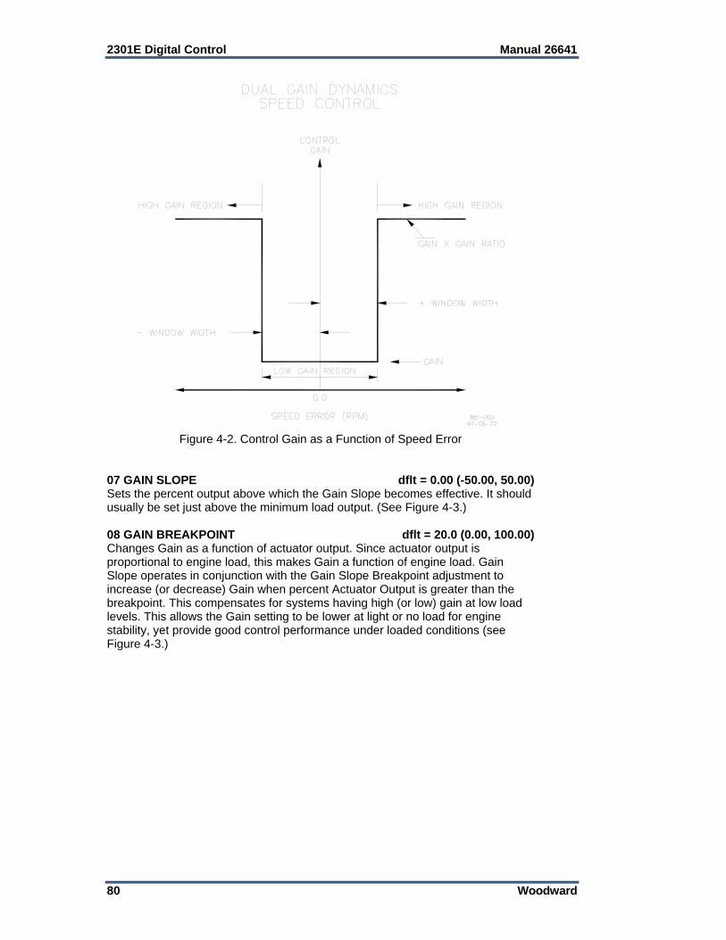
2301E Digital Control Manual 26641
80 Woodward
Figure 4-2. Control Gain as a Function of Speed Error
07 GAIN SLOPE dflt = 0.00 (-50.00, 50.00) Sets the percent output above which the Gain Slope becomes effective. It should usually be set just above the minimum load output. (See Figure 4-3.) 08 GAIN BREAKPOINT dflt = 20.0 (0.00, 100.00) Changes Gain as a function of actuator output. Since actuator output is proportional to engine load, this makes Gain a function of engine load. Gain Slope operates in conjunction with the Gain Slope Breakpoint adjustment to increase (or decrease) Gain when percent Actuator Output is greater than the breakpoint. This compensates for systems having high (or low) gain at low load levels. This allows the Gain setting to be lower at light or no load for engine stability, yet provide good control performance under loaded conditions (see Figure 4-3.)

Manual 26641 2301E Digital Control
Woodward 81
Figure 4-3. Control Gain as a Function of Fuel Demand (Load)
09 SPEED FILTER FREQ 1 (HZ) dflt = 12.00 (4.00, 20.00) Adjusts the cutoff frequency of a low-pass filter used on the engine speed sensing input (see Figure 4-4). To use this feature set the cutoff frequency below 15.9 Hz. The filter is used to attenuate engine firing frequencies. To calculate the desired filter cutoff point, use the following formulas: camshaft frequency = (engine rpm)/60 [for 2-cycle engines] = (engine rpm)/120 [for 4-cycle engines] firing frequency = camshaft frequency x number of cylinders Initially set the filter frequency to the firing frequency. As the filter frequency is reduced, steady state stability improves but transient performance may worsen. As the filter frequency is increased, steady state stability worsens but transient performance may improve.
If the calculated firing frequency is greater that 15.9 Hz, then disable the filter by setting the filter cutoff frequency at or above 15.9 Hz.
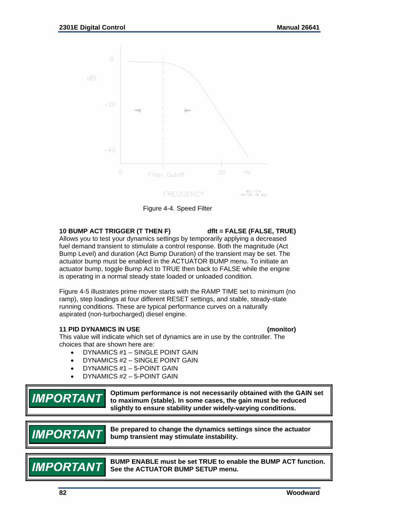
2301E Digital Control Manual 26641
82 Woodward
Figure 4-4. Speed Filter
10 BUMP ACT TRIGGER (T THEN F) dflt = FALSE (FALSE, TRUE) Allows you to test your dynamics settings by temporarily applying a decreased fuel demand transient to stimulate a control response. Both the magnitude (Act Bump Level) and duration (Act Bump Duration) of the transient may be set. The actuator bump must be enabled in the ACTUATOR BUMP menu. To initiate an actuator bump, toggle Bump Act to TRUE then back to FALSE while the engine is operating in a normal steady state loaded or unloaded condition. Figure 4-5 illustrates prime mover starts with the RAMP TIME set to minimum (no ramp), step loadings at four different RESET settings, and stable, steady-state running conditions. These are typical performance curves on a naturally aspirated (non-turbocharged) diesel engine. 11 PID DYNAMICS IN USE (monitor) This value will indicate which set of dynamics are in use by the controller. The choices that are shown here are:
DYNAMICS #1 – SINGLE POINT GAIN DYNAMICS #2 – SINGLE POINT GAIN DYNAMICS #1 – 5-POINT GAIN DYNAMICS #2 – 5-POINT GAIN
Optimum performance is not necessarily obtained with the GAIN set to maximum (stable). In some cases, the gain must be reduced slightly to ensure stability under widely-varying conditions.
Be prepared to change the dynamics settings since the actuator bump transient may stimulate instability.
BUMP ENABLE must be set TRUE to enable the BUMP ACT function. See the ACTUATOR BUMP SETUP menu.
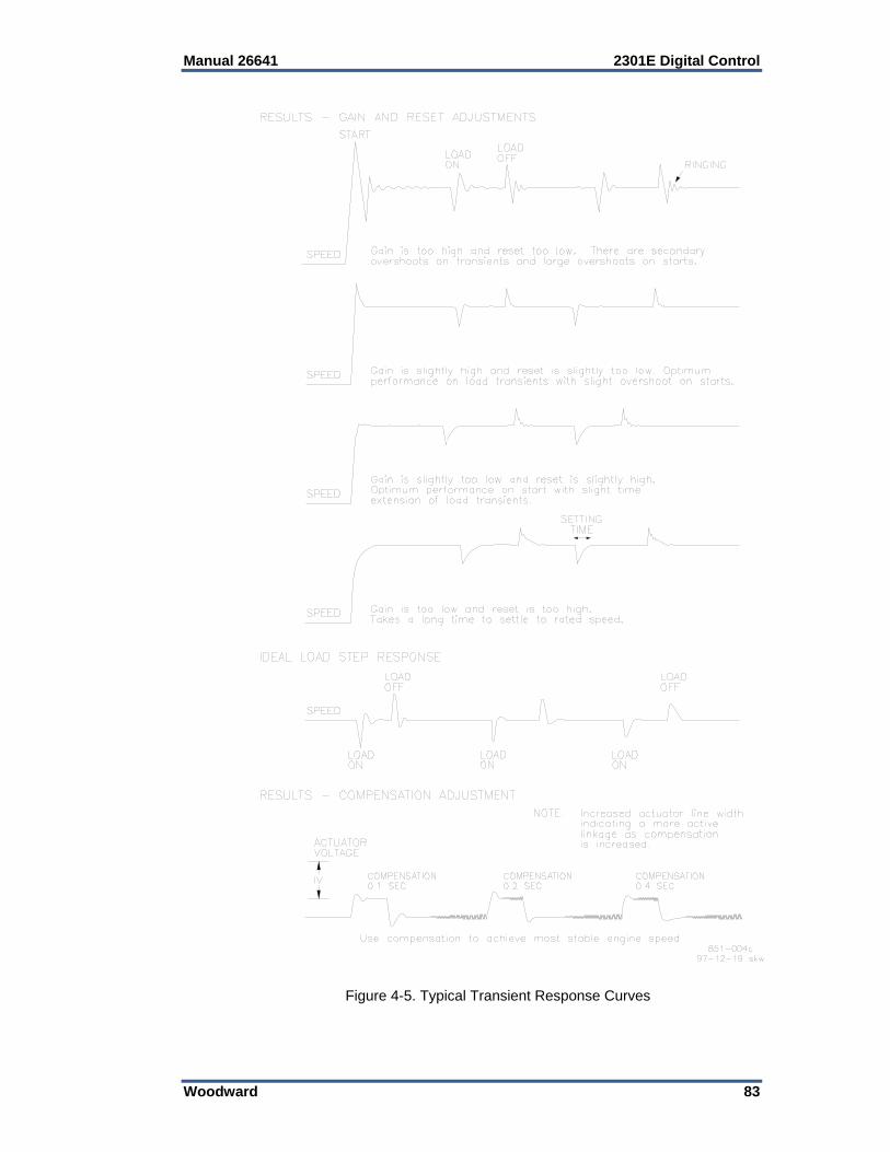
Manual 26641 2301E Digital Control
Woodward 83
Figure 4-5. Typical Transient Response Curves
2301E Digital Control Manual 26641
84 Woodward
I**Dynamics #2** The Dynamics 2 control parameters are adjusted the same as Dynamics 1 described above. To enable the use of two sets of dynamics, it is necessary to set Enable 2nd DYNAMICS w/CB below to TRUE. These parameters are in control only when the CB Aux contact input is closed or if a discrete input is configured for Select 2nd Dynamics and this input is closed.
I**Dynamics #2** parameters 04 thru 10 have the same effect on speed control response as H**Dynamics #1** parameters 01 thru 07 described above.
01 ENABLE DYNAMICS 2 W/CB dflt = FALSE (FALSE, TRUE) 02 DELAY DYN 2 ENABLE (SEC) dflt = 0.00 (0.00, 20.00) This is the delay time before dynamics #2 are used by the speed control when the "CB Aux Droop contact" or "Select 2nd Dynamics" input is activated. 03 DELAY DYN 1 ENABLE (SEC) dflt = 0.00 (0.00, 20.00) This is the delay time before Dynamics #1 are used by the speed control after the "CB Aux Droop contact" or "Select 2nd Dynamics" input is de-activated. 04 PROP GAIN 2 dflt = 2.00 (0.001, 100.00) 05 RESET 2 dflt = 1.00 (0.01, 100.00) 06 ACTUATOR COMPENSATION 2 dflt = 0.10 (0.01, 100.00) 07 WINDOW WIDTH 2 (RPM) dflt = 60.00 (1.00, 200.00) 08 GAIN RATIO 2 dflt = 1.00 (1.00, 10.00) 09 GAIN SLOPE 2 dflt = 0.00 (-50.00, 50.00) 10 GAIN BREAKPOINT 2 dflt = 20.0 (0.00, 100.00) 11 SPEED FILTER FREQ 2 (HZ) dflt = 12.00 (4.00, 20.00) 12 BUMP ACT TRIG (T THEN F) dflt = FALSE (FALSE, TRUE) 13 PID DYNAMICS IN USE (monitor) This value will indicate which set of dynamics are in use by the controller. The choices that are shown here are:
PID USING DYNAMICS 1 PID USING DYNAMICS 2 PID USING 5-SLOPE - DYNAMICS 1 PID USING 5-SLOPE - DYNAMICS 2
Manual 26641 2301E Digital Control
Woodward 85
J**Dynamics #1 5 Pt Gain** This menu and control function is enabled when Configure Menu: A**SPEED CONTROL FUNCTIONS** parameter 07 ENABLE 5 SLOPE GAIN MAP is TRUE and provides a 5-point curve as a function of prime mover load for the variable GAIN set point. The Breakpoint parameter is based on what is set in Configure: parameter ‘08 SEL GAIN FUNCTION (1,3)’. The prime mover Fuel Demand % (1) or generator kilowatt % (2) or engine speed (3) is used as the load/rpm axis. It is useful in applications that have a non-linear fuel valve (such as butterfly valves). A plot of the fuel system must be determined to properly adjust the gain of the control to match the gain of the system at all loads. See the Gas Engine Setup and Control Gain Programming Steps sections below. 01 BREAKPOINT 1A (%LD OR RPM) dflt = 99.60 (0.00, 5000.00) Set at the min load point no-load fuel demand or 0% KW. 02 GAIN @BREAKPOINT 1A dflt = 2.0 (0.001, 100.00) The no load GAIN value. 03 BREAKPOINT 1B (%LD OR RPM) dflt = 99.70 (0.01, 5000.00) The Fuel demand % or KW% at the next load breakpoint. 04 GAIN @BREAKPOINT 1B dflt = 2.0 (0.001, 100.00) The GAIN value when the load is at breakpoint B. 05 BREAKPOINT 1C (%LD OR RPM) dflt = 99.80 (0.01, 5000.00) The load % for breakpoint C. 06 GAIN @BREAKPOINT 1C dflt = 2.0 (0.001, 100.00) This is the GAIN value when the load is at breakpoint C. 07 BREAKPOINT 1D (%LD OR RPM) dflt = 99.90 (0.01, 5000.00) The load % for breakpoint D. 08 GAIN @BREAKPOINT 1D dflt = 2.0 (0.001, 100.00) The GAIN value when the load is at breakpoint D. 09 BREAKPOINT 1E (%LD OR RPM) dflt = 100.00 (0.01, 5000.00) The load % for breakpoint E. 10 GAIN @BREAKPOINT 1E dflt = 2.0 (0.001, 100.00) The GAIN value when the load is at breakpoint E. 11 RESET 1 dflt = 1.0 (0.01, 100.00) This compensates for the lag time of the engine. It adjusts the time required for the control to return the speed to zero error after a disturbance. Reset is adjusted to prevent slow hunting and to minimize speed overshoot after a load disturbance. 12 ACT COMPENSATION dflt = 0.10 (0.01, 100.00) This compensates for the actuator and fuel system time constant. Increasing compensation increases actuator activity and transient performance. 13 WINDOW WIDTH 1 (RPM) dflt = 60.00 (1.00, 200.00) The magnitude (in rpm) of speed error at which the control automatically switches to fast response. The control uses the absolute value of speed error to make this switch. The absolute value is the difference between the speed reference and the speed. A window width that is too narrow results in cycling that always factors in the gain ratio (see Figure 4-2).
2301E Digital Control Manual 26641
86 Woodward
14 GAIN RATIO 1 dflt = 1.00 (1.00, 10.00) The ratio of the gain setting at steady state to the gain setting during transient conditions. The gain ratio operates in conjunction with the Window Width and gain adjustments by multiplying the gain set point by the gain ratio when the speed error is greater than the window width. This makes the control dynamics fast enough to minimize engine-speed overshoot on start-up and to reduce the magnitude of speed error when loads are changing. This allows a lower gain at steady state for better stability and reduced steady-state actuator linkage movement (see Figure 4-2). 15 SPEED FILTER FREQ 1 (HZ) dflt = 12.00 (4.00, 20.00) Adjusts the cutoff frequency of a low pass filter used on the engine speed sensing input (see Figure 4-4). To use this feature set the cutoff frequency below 15.9 Hz. The filter is used to attenuate engine firing frequencies. To calculate the desired filter cutoff point, use the following formulas: camshaft frequency = (engine rpm)/60 [for 2-cycle engines] = (engine rpm)/120 [for 4-cycle engines] firing frequency = camshaft frequency x number of cylinders Initially set the filter frequency to the firing frequency. As the filter frequency is reduced, steady state stability improves but transient performance may worsen. As the filter frequency is increased, steady state stability worsens but transient performance may improve.
If the calculated firing frequency is greater than 15.9 Hz, then disable the filter by setting the filter cutoff frequency at or above 15.9 Hz.
16 BUMP ACT TRIG (T THEN F) dflt = FALSE (FALSE, TRUE) This test allows you to test your dynamics settings by temporarily applying a decreased fuel demand transient to stimulate a control response. Both the magnitude (Act Bump Level) and duration (Act Bump Duration) of the transient may be set. The actuator bump must be enabled in the ACTUATOR BUMP SETUP menu. To initiate an actuator bump, toggle Bump Act to TRUE then back to FALSE while the engine is operating in a normal steady state loaded or unloaded condition. 17 PID DYNAMICS IN USE (monitor) This value will indicate which set of dynamics are in use by the controller. The choices that are shown here are:
PID USING DYNAMICS 1 PID USING DYNAMICS 2 PID USING 5-SLOPE - DYNAMICS 1 PID USING 5-SLOPE - DYNAMICS 2
Manual 26641 2301E Digital Control
Woodward 87
K**Dynamics #2 5 Pt Gain** The Dynamics 2 control parameters are adjusted the same as Dynamics 1 described above. These parameters are in control only when the CB Aux contact input is closed, or if a discrete input is configured for Select 2nd Dynamics and this input is closed.
K**Dynamics #2 5 Pt Gain** parameters 04 thru 19 have the same effect on speed control response as J**Dynamics #2 5 Pt Gain** parameters 01 thru 16 described above.
01 ENABLE DYNAMICS 2 W/CB dflt = FALSE (FALSE, TRUE) When TRUE, the second set of dynamics is enabled when the circuit breaker auxiliary contact or Select 2nd Dynamics contact is closed. When this prompt is FALSE, only Dynamics 1 with be used to set speed control response. 02 DELAY DYN 2 ENABLE (SEC) dflt = 0.00 (0.00, 20.00) A delay time, in seconds, that dynamics #1 will continue to be used by the speed control after the CB contact. 03 DELAY DYN 1 ENABLE (SEC) dflt = 0.00 (0.00, 20.00) The delay time that dynamics #2 will continue to be used before switching to dynamics #1. 04 BREAKPOINT 2A (%LD OR RPM) dflt = 99.60 (0.01, 5000.00) 05 GAIN @BREAKPOINT 2A dflt = 2.0 (0.001, 100.00) 06 BREAKPOINT 2B (%LD OR RPM) dflt = 99.70 (0.01, 5000.00) 07 GAIN @BREAKPOINT 2B dflt = 2.0 (0.001, 100.00) 08 BREAKPOINT 2C (%LD OR RPM) dflt = 99.80 (0.01, 5000.00) 09 GAIN @BREAKPOINT 2C dflt = 2.0 (0.001, 100.00) 10 BREAKPOINT 2D (%LD OR RPM) dflt = 99.90 (0.01, 5000.00) 11 GAIN BREAKPOINT 2D dflt = 2.0 (0.001, 100.00) 12 BREAKPOINT 2E (%LD OR RPM) dflt = 100.00 (0.01, 5000.00) 13 GAIN BREAKPOINT 2E dflt = 2.0 (0.001, 100.00) 14 RESET 2 dflt = 1.00 (0.01, 100.00) 15 ACTUATOR COMPENSATION 2 dflt = 0.10 (0.01, 100.00) 16 WINDOW WIDTH 2 (RPM) dflt = 60.00 (1.00, 200.00) 17 GAIN RATIO 2 dflt = 1.0 (1.00, 10.00) 18 SPEED FILTER FREQ 2 (HZ) dflt = 12.00 (4.00, 20.00) 19 BUMP ACT TRIG (T THEN F) dflt = FALSE (FALSE, TRUE)
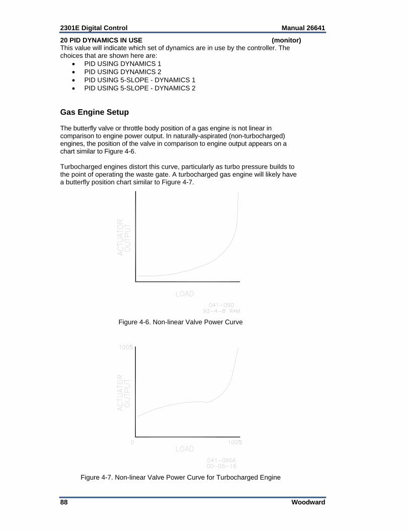
2301E Digital Control Manual 26641
88 Woodward
20 PID DYNAMICS IN USE (monitor) This value will indicate which set of dynamics are in use by the controller. The choices that are shown here are:
PID USING DYNAMICS 1 PID USING DYNAMICS 2 PID USING 5-SLOPE - DYNAMICS 1 PID USING 5-SLOPE - DYNAMICS 2
Gas Engine Setup The butterfly valve or throttle body position of a gas engine is not linear in comparison to engine power output. In naturally-aspirated (non-turbocharged) engines, the position of the valve in comparison to engine output appears on a chart similar to Figure 4-6. Turbocharged engines distort this curve, particularly as turbo pressure builds to the point of operating the waste gate. A turbocharged gas engine will likely have a butterfly position chart similar to Figure 4-7.
Figure 4-6. Non-linear Valve Power Curve
Figure 4-7. Non-linear Valve Power Curve for Turbocharged Engine
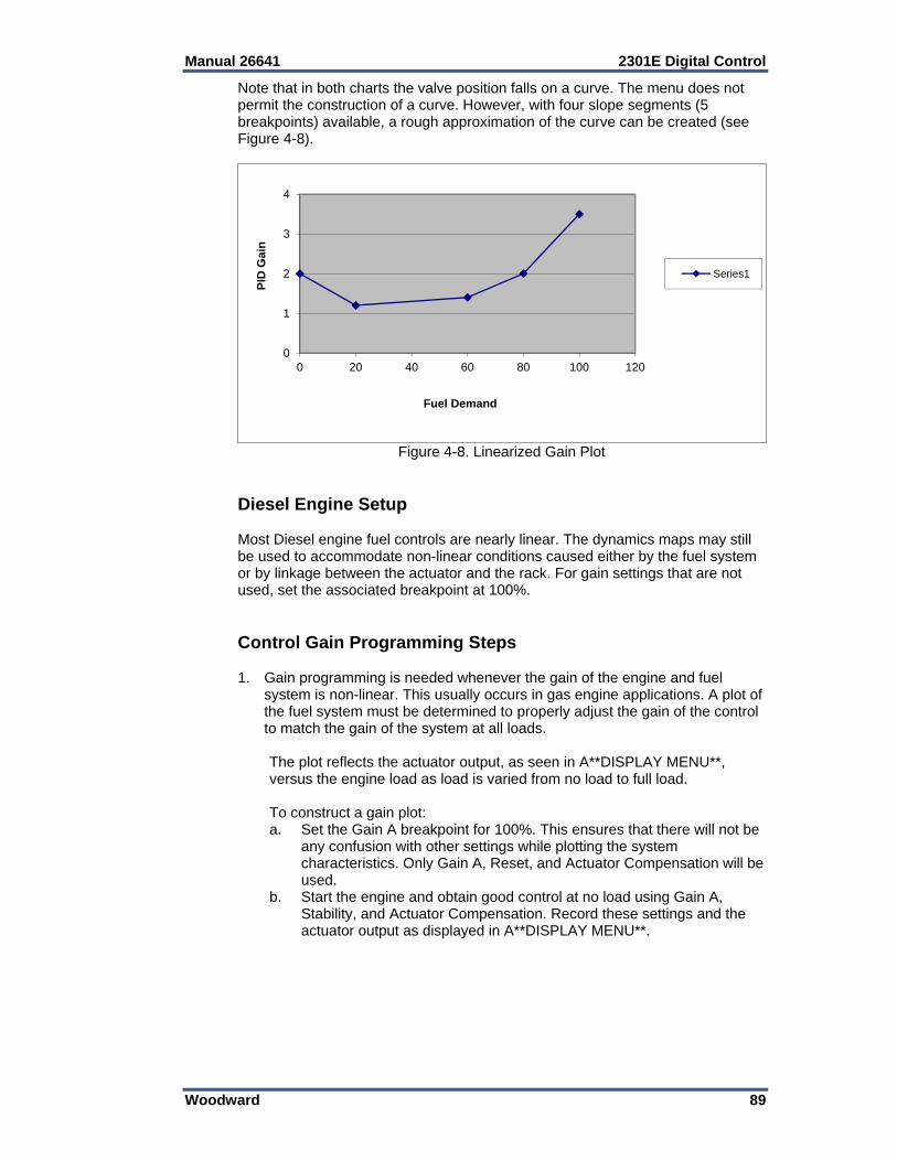
Manual 26641 2301E Digital Control
Woodward 89
Note that in both charts the valve position falls on a curve. The menu does not permit the construction of a curve. However, with four slope segments (5 breakpoints) available, a rough approximation of the curve can be created (see Figure 4-8).
Figure 4-8. Linearized Gain Plot
Diesel Engine Setup Most Diesel engine fuel controls are nearly linear. The dynamics maps may still be used to accommodate non-linear conditions caused either by the fuel system or by linkage between the actuator and the rack. For gain settings that are not used, set the associated breakpoint at 100%. Control Gain Programming Steps 1. Gain programming is needed whenever the gain of the engine and fuel
system is non-linear. This usually occurs in gas engine applications. A plot of the fuel system must be determined to properly adjust the gain of the control to match the gain of the system at all loads.
The plot reflects the actuator output, as seen in A**DISPLAY MENU**,
versus the engine load as load is varied from no load to full load. To construct a gain plot: a. Set the Gain A breakpoint for 100%. This ensures that there will not be
any confusion with other settings while plotting the system characteristics. Only Gain A, Reset, and Actuator Compensation will be used.
b. Start the engine and obtain good control at no load using Gain A, Stability, and Actuator Compensation. Record these settings and the actuator output as displayed in A**DISPLAY MENU**.
0
1
2
3
4
0 20 40 60 80 100 120
PID
Gai
n
Fuel Demand
Series1
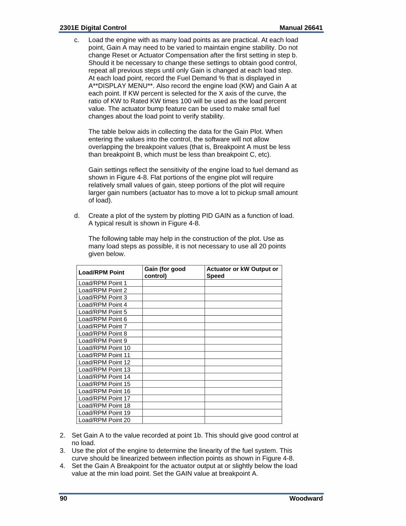
2301E Digital Control Manual 26641
90 Woodward
c. Load the engine with as many load points as are practical. At each load point, Gain A may need to be varied to maintain engine stability. Do not change Reset or Actuator Compensation after the first setting in step b. Should it be necessary to change these settings to obtain good control, repeat all previous steps until only Gain is changed at each load step. At each load point, record the Fuel Demand % that is displayed in A**DISPLAY MENU**. Also record the engine load (KW) and Gain A at each point. If KW percent is selected for the X axis of the curve, the ratio of KW to Rated KW times 100 will be used as the load percent value. The actuator bump feature can be used to make small fuel changes about the load point to verify stability.
The table below aids in collecting the data for the Gain Plot. When
entering the values into the control, the software will not allow overlapping the breakpoint values (that is, Breakpoint A must be less than breakpoint B, which must be less than breakpoint C, etc).
Gain settings reflect the sensitivity of the engine load to fuel demand as
shown in Figure 4-8. Flat portions of the engine plot will require relatively small values of gain, steep portions of the plot will require larger gain numbers (actuator has to move a lot to pickup small amount of load).
d. Create a plot of the system by plotting PID GAIN as a function of load.
A typical result is shown in Figure 4-8. The following table may help in the construction of the plot. Use as
many load steps as possible, it is not necessary to use all 20 points given below.
Load/RPM Point Gain (for good control)
Actuator or kW Output or Speed
Load/RPM Point 1 Load/RPM Point 2 Load/RPM Point 3 Load/RPM Point 4 Load/RPM Point 5 Load/RPM Point 6 Load/RPM Point 7 Load/RPM Point 8 Load/RPM Point 9 Load/RPM Point 10 Load/RPM Point 11 Load/RPM Point 12 Load/RPM Point 13 Load/RPM Point 14 Load/RPM Point 15 Load/RPM Point 16 Load/RPM Point 17 Load/RPM Point 18 Load/RPM Point 19 Load/RPM Point 20
2. Set Gain A to the value recorded at point 1b. This should give good control at
no load. 3. Use the plot of the engine to determine the linearity of the fuel system. This
curve should be linearized between inflection points as shown in Figure 4-8. 4. Set the Gain A Breakpoint for the actuator output at or slightly below the load
value at the min load point. Set the GAIN value at breakpoint A.
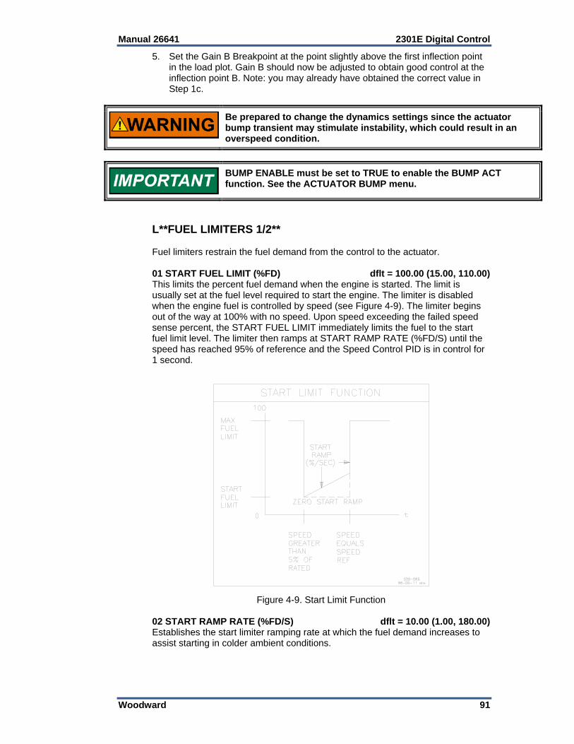
Manual 26641 2301E Digital Control
Woodward 91
5. Set the Gain B Breakpoint at the point slightly above the first inflection point in the load plot. Gain B should now be adjusted to obtain good control at the inflection point B. Note: you may already have obtained the correct value in Step 1c.
Be prepared to change the dynamics settings since the actuator bump transient may stimulate instability, which could result in an overspeed condition.
BUMP ENABLE must be set to TRUE to enable the BUMP ACT function. See the ACTUATOR BUMP menu.
L**FUEL LIMITERS 1/2** Fuel limiters restrain the fuel demand from the control to the actuator. 01 START FUEL LIMIT (%FD) dflt = 100.00 (15.00, 110.00) This limits the percent fuel demand when the engine is started. The limit is usually set at the fuel level required to start the engine. The limiter is disabled when the engine fuel is controlled by speed (see Figure 4-9). The limiter begins out of the way at 100% with no speed. Upon speed exceeding the failed speed sense percent, the START FUEL LIMIT immediately limits the fuel to the start fuel limit level. The limiter then ramps at START RAMP RATE (%FD/S) until the speed has reached 95% of reference and the Speed Control PID is in control for 1 second.
Figure 4-9. Start Limit Function
02 START RAMP RATE (%FD/S) dflt = 10.00 (1.00, 180.00) Establishes the start limiter ramping rate at which the fuel demand increases to assist starting in colder ambient conditions.
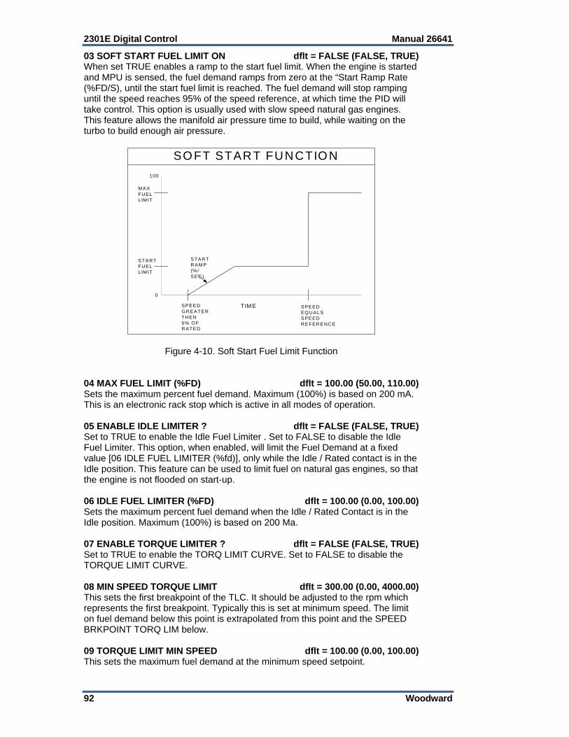
2301E Digital Control Manual 26641
92 Woodward
03 SOFT START FUEL LIMIT ON dflt = FALSE (FALSE, TRUE) When set TRUE enables a ramp to the start fuel limit. When the engine is started and MPU is sensed, the fuel demand ramps from zero at the “Start Ramp Rate (%FD/S), until the start fuel limit is reached. The fuel demand will stop ramping until the speed reaches 95% of the speed reference, at which time the PID will take control. This option is usually used with slow speed natural gas engines. This feature allows the manifold air pressure time to build, while waiting on the turbo to build enough air pressure.
SPEEDG REATERTH EN5% O FRATED
M AXFUELLIM IT
STARTFUELLIM IT
STARTRAM P(% /SEC)
SPEEDEQ UALSSPEEDREFERENCE
TIM E
0
100
SO FT START FUNCTION
Figure 4-10. Soft Start Fuel Limit Function 04 MAX FUEL LIMIT (%FD) dflt = 100.00 (50.00, 110.00) Sets the maximum percent fuel demand. Maximum (100%) is based on 200 mA. This is an electronic rack stop which is active in all modes of operation. 05 ENABLE IDLE LIMITER ? dflt = FALSE (FALSE, TRUE) Set to TRUE to enable the Idle Fuel Limiter . Set to FALSE to disable the Idle Fuel Limiter. This option, when enabled, will limit the Fuel Demand at a fixed value [06 IDLE FUEL LIMITER (%fd)], only while the Idle / Rated contact is in the Idle position. This feature can be used to limit fuel on natural gas engines, so that the engine is not flooded on start-up. 06 IDLE FUEL LIMITER (%FD) dflt = 100.00 (0.00, 100.00) Sets the maximum percent fuel demand when the Idle / Rated Contact is in the Idle position. Maximum (100%) is based on 200 Ma. 07 ENABLE TORQUE LIMITER ? dflt = FALSE (FALSE, TRUE) Set to TRUE to enable the TORQ LIMIT CURVE. Set to FALSE to disable the TORQUE LIMIT CURVE. 08 MIN SPEED TORQUE LIMIT dflt = 300.00 (0.00, 4000.00) This sets the first breakpoint of the TLC. It should be adjusted to the rpm which represents the first breakpoint. Typically this is set at minimum speed. The limit on fuel demand below this point is extrapolated from this point and the SPEED BRKPOINT TORQ LIM below. 09 TORQUE LIMIT MIN SPEED dflt = 100.00 (0.00, 100.00) This sets the maximum fuel demand at the minimum speed setpoint.
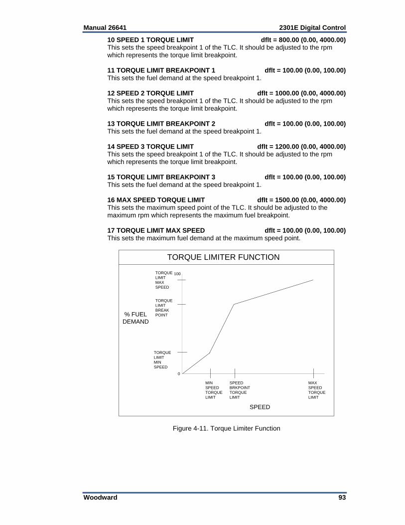
Manual 26641 2301E Digital Control
Woodward 93
10 SPEED 1 TORQUE LIMIT dflt = 800.00 (0.00, 4000.00) This sets the speed breakpoint 1 of the TLC. It should be adjusted to the rpm which represents the torque limit breakpoint. 11 TORQUE LIMIT BREAKPOINT 1 dflt = 100.00 (0.00, 100.00) This sets the fuel demand at the speed breakpoint 1. 12 SPEED 2 TORQUE LIMIT dflt = 1000.00 (0.00, 4000.00) This sets the speed breakpoint 1 of the TLC. It should be adjusted to the rpm which represents the torque limit breakpoint. 13 TORQUE LIMIT BREAKPOINT 2 dflt = 100.00 (0.00, 100.00) This sets the fuel demand at the speed breakpoint 1. 14 SPEED 3 TORQUE LIMIT dflt = 1200.00 (0.00, 4000.00) This sets the speed breakpoint 1 of the TLC. It should be adjusted to the rpm which represents the torque limit breakpoint. 15 TORQUE LIMIT BREAKPOINT 3 dflt = 100.00 (0.00, 100.00) This sets the fuel demand at the speed breakpoint 1. 16 MAX SPEED TORQUE LIMIT dflt = 1500.00 (0.00, 4000.00) This sets the maximum speed point of the TLC. It should be adjusted to the maximum rpm which represents the maximum fuel breakpoint. 17 TORQUE LIMIT MAX SPEED dflt = 100.00 (0.00, 100.00) This sets the maximum fuel demand at the maximum speed point.
TORQUELIMITMAXSPEED
TORQUELIMITMINSPEED
MINSPEEDTORQUELIMIT
SPEED
0
100
TORQUE LIMITER FUNCTION
% FUELDEMAND
TORQUELIMITBREAKPOINT
SPEEDBRKPOINTTORQUELIMIT
MAXSPEEDTORQUELIMIT
Figure 4-11. Torque Limiter Function
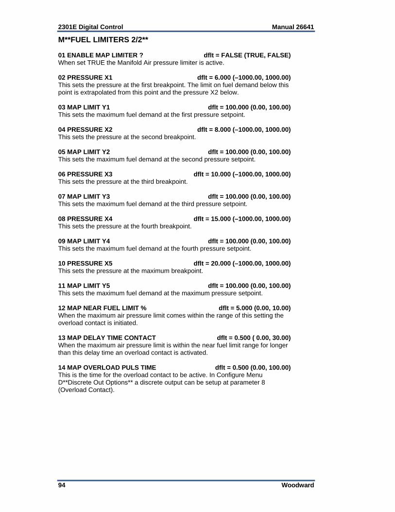
2301E Digital Control Manual 26641
94 Woodward
M**FUEL LIMITERS 2/2** 01 ENABLE MAP LIMITER ? dflt = FALSE (TRUE, FALSE) When set TRUE the Manifold Air pressure limiter is active. 02 PRESSURE X1 dflt = 6.000 (–1000.00, 1000.00) This sets the pressure at the first breakpoint. The limit on fuel demand below this point is extrapolated from this point and the pressure X2 below. 03 MAP LIMIT Y1 dflt = 100.000 (0.00, 100.00) This sets the maximum fuel demand at the first pressure setpoint. 04 PRESSURE X2 dflt = 8.000 (–1000.00, 1000.00) This sets the pressure at the second breakpoint. 05 MAP LIMIT Y2 dflt = 100.000 (0.00, 100.00) This sets the maximum fuel demand at the second pressure setpoint. 06 PRESSURE X3 dflt = 10.000 (–1000.00, 1000.00) This sets the pressure at the third breakpoint. 07 MAP LIMIT Y3 dflt = 100.000 (0.00, 100.00) This sets the maximum fuel demand at the third pressure setpoint. 08 PRESSURE X4 dflt = 15.000 (–1000.00, 1000.00) This sets the pressure at the fourth breakpoint. 09 MAP LIMIT Y4 dflt = 100.000 (0.00, 100.00) This sets the maximum fuel demand at the fourth pressure setpoint. 10 PRESSURE X5 dflt = 20.000 (–1000.00, 1000.00) This sets the pressure at the maximum breakpoint. 11 MAP LIMIT Y5 dflt = 100.000 (0.00, 100.00) This sets the maximum fuel demand at the maximum pressure setpoint. 12 MAP NEAR FUEL LIMIT % dflt = 5.000 (0.00, 10.00) When the maximum air pressure limit comes within the range of this setting the overload contact is initiated. 13 MAP DELAY TIME CONTACT dflt = 0.500 ( 0.00, 30.00) When the maximum air pressure limit is within the near fuel limit range for longer than this delay time an overload contact is activated. 14 MAP OVERLOAD PULS TIME dflt = 0.500 (0.00, 100.00) This is the time for the overload contact to be active. In Configure Menu D**Discrete Out Options** a discrete output can be setup at parameter 8 (Overload Contact).
Manual 26641 2301E Digital Control
Woodward 95
MAP LIMIT Y1
PRESS
X1
MANIFOLD AIR PRESSURE
0
100
MAP LIMITER FUNCTION
% FUELDEMAND
MAP LIMIT Y2
MAP LIMIT Y5
MAP LIMIT Y3
MAP LIMIT Y4
PRESS
X2
PRESS
X3
PRESS
X4
PRESS
X5
Figure 4-12. MAP Limiter Function
N**LOAD SETTINGS** The Load Setting section is the set-up of the generator load control parameters. 01 KW LOAD DROOP % dflt = 5.000 (0.00, 12.00) This is the percentage of rated speed the speed reference will droop when the generator load (KW) is increased to maximum load. Set to the desired droop percent. 02 LOAD LEVEL VOLTAGE dflt = 6.000 (0.10, 9.00) Sets the voltage level of the load. The value of 6.0 is typical for most analog load sharing schemes. 03 LOAD SHARE GAIN dflt = 1.000 (0.01, 10.00) Sets the load sharing gain. A too-high gain will result in unstable load sharing between the units. 04 ENABLE ACT POS DROOP dflt = FALSE (TRUE, FALSE) This enables the actuator position droop feature. Actuator position droop is a feature that gives the control a speed droop percentage based on the actuator position (fuel demand). This feature would be used if the control was not capable of receiving a PT and CT signal for KW droop, or if for testing purposes. 05 ACT POSITION DROOP % dflt = 0.00 (0.00, 100.00) The actuator dependant droop percentage setting, for proper droop control set the below parameters 06 and 07 first. If load (kW) droop is used (GEN PT and GEN CT are connected) set this parameter to 0.

2301E Digital Control Manual 26641
96 Woodward
06 ACT OUT AT RATED NO LOAD dflt = 20.00 (0.00, 100.00) The minimum setting where actuator position droop is calculated from. Adjust this setting at the same reading of the Fuel Demand % when engine is running at rated rpm but with no load. 07 ACT OUT RATED FULL LOAD dflt = 80.00 (0.00, 100.00) The maximum setting where actuator position droop is calculated from. Adjust this setting at the same reading of the Fuel Demand % when engine is running at rated rpm but with full load. 08 BASE LOAD MINIMUM (KW) dflt = 20.000 (10.00, 30000.00) The minimum value the base load reference will ramp to when the external lower switch at terminal 36 is closed. 09 BASE LOAD REFERENCE (KW) dflt = 50.000 (0.00, 30000.00) Enter the internal Baseload set point. This sets the initial internal set point of the Baseload Reference Ramp when the Load Control enters Base Load mode. 10 BASE LOAD MAXIMUM (KW) dflt = 110.000 (10.00, 30000.00) The maximum value the base load reference will ramp to when the external raise switch at terminal 35 is closed. 11 BASELOAD RAISE TIME (SEC) dflt = 60.000 (1.00, 600.00) The time for the reference to ramp from baseload minimum to baseload load maximum values entered above. 12 BASELOAD LOWER TIME (SEC) dflt = 60.000 (1.00, 600.00) The time for the reference to ramp from baseload maximum to baseload load minimum values entered above. 13 UNLOAD TRIP LEVEL (KW) dflt = 5.000 (0.00, 30000.00) Enter the unload trip level set point. This sets the load level that the unit unloads to following an Unload command. When the Load switch is opened to unload, the generator unloads to this KW value. The Discrete output 4 will then change state momentarily to give a breaker open command. 14 LOADING RATE (KW/SEC) dflt = 20.000 (1.00, 600.00) Enter the loading rate. This sets the rate at which the Load Ramp will increase for soft loading. 15 UNLOADING RATE (KW/SEC) dflt = 20.000 (1.00, 600.00) Enter the unloading rate. This sets the rate at which the Load Ramp will decrease for soft unloading. 16 ENABLE FAST LOAD RATE dflt = FALSE (TRUE, FALSE) Set to TRUE if the function to activate a faster loading ramp rate than the LOADING RATE entered above when the system load level is high. 17 FAST RAMP ENABLE LOAD (%) dflt = 80.000 (1.00, 110.00) When the system load, as measured through the load sharing lines, is determined to by above this percentage the soft load ramp rate will switch to a faster rate to allow this oncoming unit to pick up it share of the load faster. 18 FAST RAMP RATE (KW/SEC) dflt = 60.000 (1.00, 600.00) Enter the loading rate at which the load will increase when the system load is above the percentage entered above.
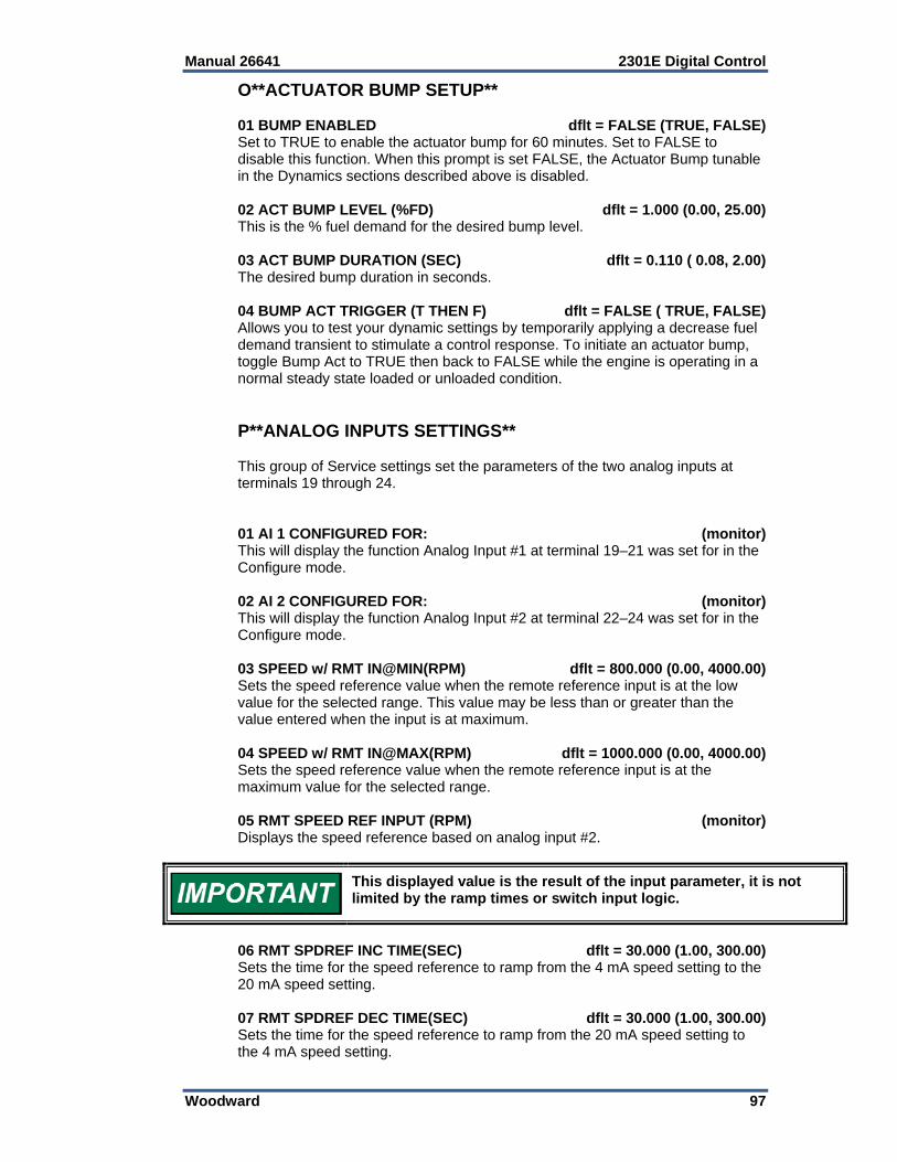
Manual 26641 2301E Digital Control
Woodward 97
O**ACTUATOR BUMP SETUP** 01 BUMP ENABLED dflt = FALSE (TRUE, FALSE) Set to TRUE to enable the actuator bump for 60 minutes. Set to FALSE to disable this function. When this prompt is set FALSE, the Actuator Bump tunable in the Dynamics sections described above is disabled. 02 ACT BUMP LEVEL (%FD) dflt = 1.000 (0.00, 25.00) This is the % fuel demand for the desired bump level. 03 ACT BUMP DURATION (SEC) dflt = 0.110 ( 0.08, 2.00) The desired bump duration in seconds. 04 BUMP ACT TRIGGER (T THEN F) dflt = FALSE ( TRUE, FALSE) Allows you to test your dynamic settings by temporarily applying a decrease fuel demand transient to stimulate a control response. To initiate an actuator bump, toggle Bump Act to TRUE then back to FALSE while the engine is operating in a normal steady state loaded or unloaded condition. P**ANALOG INPUTS SETTINGS** This group of Service settings set the parameters of the two analog inputs at terminals 19 through 24. 01 AI 1 CONFIGURED FOR: (monitor) This will display the function Analog Input #1 at terminal 19–21 was set for in the Configure mode. 02 AI 2 CONFIGURED FOR: (monitor) This will display the function Analog Input #2 at terminal 22–24 was set for in the Configure mode. 03 SPEED w/ RMT IN@MIN(RPM) dflt = 800.000 (0.00, 4000.00) Sets the speed reference value when the remote reference input is at the low value for the selected range. This value may be less than or greater than the value entered when the input is at maximum. 04 SPEED w/ RMT IN@MAX(RPM) dflt = 1000.000 (0.00, 4000.00) Sets the speed reference value when the remote reference input is at the maximum value for the selected range. 05 RMT SPEED REF INPUT (RPM) (monitor) Displays the speed reference based on analog input #2.
This displayed value is the result of the input parameter, it is not limited by the ramp times or switch input logic.
06 RMT SPDREF INC TIME(SEC) dflt = 30.000 (1.00, 300.00) Sets the time for the speed reference to ramp from the 4 mA speed setting to the 20 mA speed setting. 07 RMT SPDREF DEC TIME(SEC) dflt = 30.000 (1.00, 300.00) Sets the time for the speed reference to ramp from the 20 mA speed setting to the 4 mA speed setting.
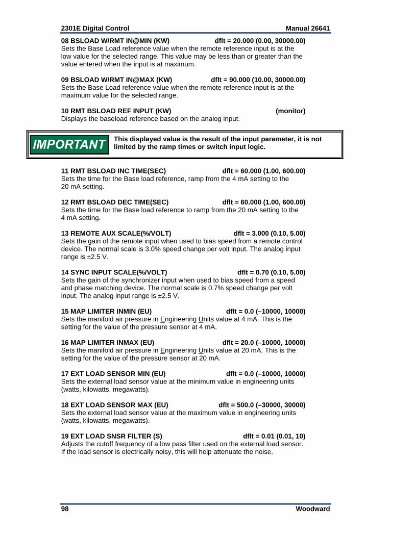
2301E Digital Control Manual 26641
98 Woodward
08 BSLOAD W/RMT IN@MIN (KW) dflt = 20.000 (0.00, 30000.00) Sets the Base Load reference value when the remote reference input is at the low value for the selected range. This value may be less than or greater than the value entered when the input is at maximum. 09 BSLOAD W/RMT IN@MAX (KW) dflt = 90.000 (10.00, 30000.00) Sets the Base Load reference value when the remote reference input is at the maximum value for the selected range. 10 RMT BSLOAD REF INPUT (KW) (monitor) Displays the baseload reference based on the analog input.
This displayed value is the result of the input parameter, it is not limited by the ramp times or switch input logic.
11 RMT BSLOAD INC TIME(SEC) dflt = 60.000 (1.00, 600.00) Sets the time for the Base load reference, ramp from the 4 mA setting to the 20 mA setting. 12 RMT BSLOAD DEC TIME(SEC) dflt = 60.000 (1.00, 600.00) Sets the time for the Base load reference to ramp from the 20 mA setting to the 4 mA setting. 13 REMOTE AUX SCALE(%/VOLT) dflt = 3.000 (0.10, 5.00) Sets the gain of the remote input when used to bias speed from a remote control device. The normal scale is 3.0% speed change per volt input. The analog input range is ±2.5 V. 14 SYNC INPUT SCALE(%/VOLT) dflt = 0.70 (0.10, 5.00) Sets the gain of the synchronizer input when used to bias speed from a speed and phase matching device. The normal scale is 0.7% speed change per volt input. The analog input range is ±2.5 V. 15 MAP LIMITER INMIN (EU) dflt = 0.0 (–10000, 10000) Sets the manifold air pressure in Engineering Units value at 4 mA. This is the setting for the value of the pressure sensor at 4 mA. 16 MAP LIMITER INMAX (EU) dflt = 20.0 (–10000, 10000) Sets the manifold air pressure in Engineering Units value at 20 mA. This is the setting for the value of the pressure sensor at 20 mA. 17 EXT LOAD SENSOR MIN (EU) dflt = 0.0 (–10000, 10000) Sets the external load sensor value at the minimum value in engineering units (watts, kilowatts, megawatts). 18 EXT LOAD SENSOR MAX (EU) dflt = 500.0 (–30000, 30000) Sets the external load sensor value at the maximum value in engineering units (watts, kilowatts, megawatts). 19 EXT LOAD SNSR FILTER (S) dflt = 0.01 (0.01, 10) Adjusts the cutoff frequency of a low pass filter used on the external load sensor. If the load sensor is electrically noisy, this will help attenuate the noise.
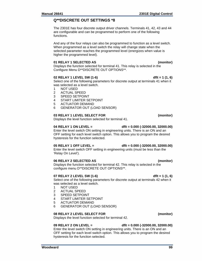
Manual 26641 2301E Digital Control
Woodward 99
Q**DISCRETE OUT SETTINGS *8 The 2301E has four discrete output driver channels. Terminals 41, 42, 43 and 44 are configurable and can be programmed to perform one of the following functions. And any of the four relays can also be programmed to function as a level switch. When programmed as a level switch the relay will change state when the selected parameter reaches the programmed level (energizes when value is higher the programmed level). 01 RELAY 1 SELECTED AS (monitor) Displays the function selected for terminal 41. This relay is selected in the Configure Menu D**DISCRETE OUT OPTIONS**. 02 RELAY 1 LEVEL SW (1-6) dflt = 1 (1, 6) Select one of the following parameters for discrete output at terminals 41 when it was selected as a level switch. 1 NOT USED 2 ACTUAL SPEED 3 SPEED SETPOINT 4 START LIMITER SETPOINT 5 ACTUATOR DEMAND 6 GENERATOR OUT (LOAD SENSOR) 03 RELAY 1 LEVEL SELECT FOR (monitor) Displays the level function selected for terminal 41. 04 RELAY 1 ON LEVEL = dflt = 0.000 (-32000.00, 32000.00) Enter the level switch ON setting in engineering units. There is an ON and an OFF setting for each level switch option. This allows you to program the desired hysteresis for the function selected. 05 RELAY 1 OFF LEVEL = dflt = 0.000 (-32000.00, 32000.00) Enter the level switch OFF setting in engineering units (must be less than the ‘Relay On Level’). 06 RELAY 2 SELECTED AS (monitor) Displays the function selected for terminal 42. This relay is selected in the configure menu D**DISCRETE OUT OPTIONS**. 07 RELAY 2 LEVEL SW (1-6) dflt = 1 (1, 6) Select one of the following parameters for discrete output at terminals 42 when it was selected as a level switch. 1 NOT USED 2 ACTUAL SPEED 3 SPEED SETPOINT 4 START LIMITER SETPOINT 5 ACTUATOR DEMAND 6 GENERATOR OUT (LOAD SENSOR) 08 RELAY 2 LEVEL SELECT FOR (monitor) Displays the level function selected for terminal 42. 09 RELAY 2 ON LEVEL = dflt = 0.000 (-32000.00, 32000.00) Enter the level switch ON setting in engineering units. There is an ON and an OFF setting for each level switch option. This allows you to program the desired hysteresis for the function selected.
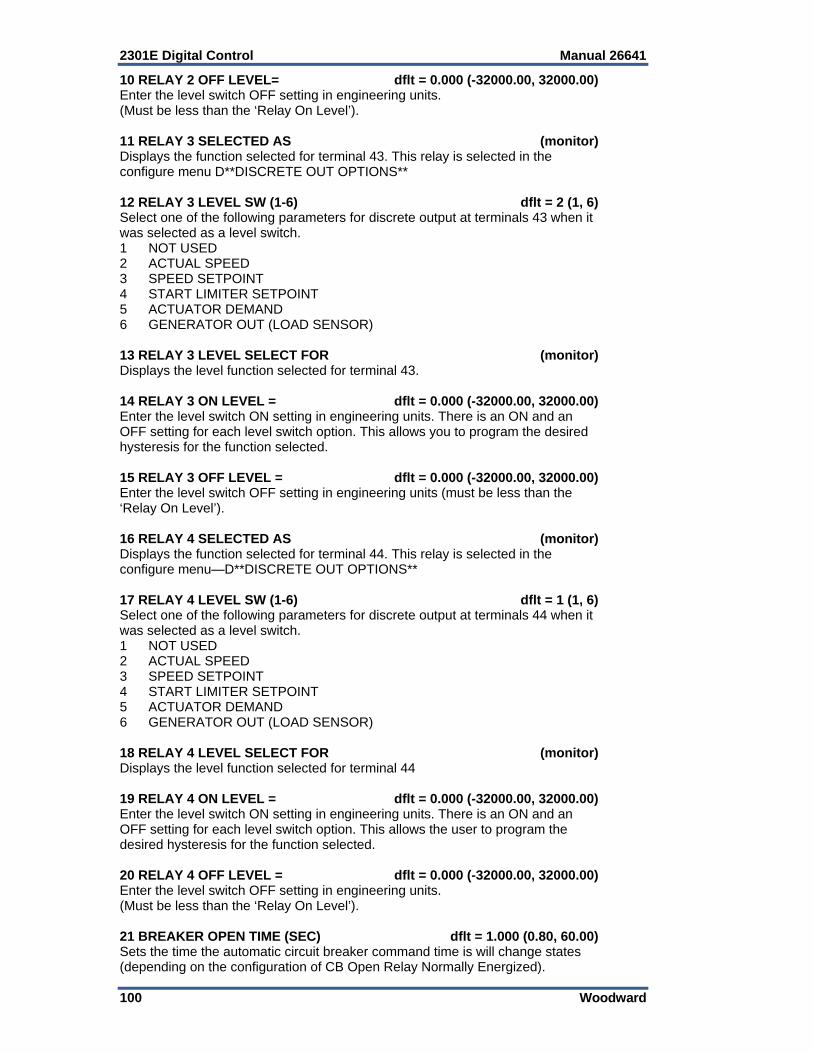
2301E Digital Control Manual 26641
100 Woodward
10 RELAY 2 OFF LEVEL= dflt = 0.000 (-32000.00, 32000.00) Enter the level switch OFF setting in engineering units. (Must be less than the ‘Relay On Level’). 11 RELAY 3 SELECTED AS (monitor) Displays the function selected for terminal 43. This relay is selected in the configure menu D**DISCRETE OUT OPTIONS** 12 RELAY 3 LEVEL SW (1-6) dflt = 2 (1, 6) Select one of the following parameters for discrete output at terminals 43 when it was selected as a level switch. 1 NOT USED 2 ACTUAL SPEED 3 SPEED SETPOINT 4 START LIMITER SETPOINT 5 ACTUATOR DEMAND 6 GENERATOR OUT (LOAD SENSOR) 13 RELAY 3 LEVEL SELECT FOR (monitor) Displays the level function selected for terminal 43. 14 RELAY 3 ON LEVEL = dflt = 0.000 (-32000.00, 32000.00) Enter the level switch ON setting in engineering units. There is an ON and an OFF setting for each level switch option. This allows you to program the desired hysteresis for the function selected. 15 RELAY 3 OFF LEVEL = dflt = 0.000 (-32000.00, 32000.00) Enter the level switch OFF setting in engineering units (must be less than the ‘Relay On Level’). 16 RELAY 4 SELECTED AS (monitor) Displays the function selected for terminal 44. This relay is selected in the configure menu—D**DISCRETE OUT OPTIONS** 17 RELAY 4 LEVEL SW (1-6) dflt = 1 (1, 6) Select one of the following parameters for discrete output at terminals 44 when it was selected as a level switch. 1 NOT USED 2 ACTUAL SPEED 3 SPEED SETPOINT 4 START LIMITER SETPOINT 5 ACTUATOR DEMAND 6 GENERATOR OUT (LOAD SENSOR) 18 RELAY 4 LEVEL SELECT FOR (monitor) Displays the level function selected for terminal 44 19 RELAY 4 ON LEVEL = dflt = 0.000 (-32000.00, 32000.00) Enter the level switch ON setting in engineering units. There is an ON and an OFF setting for each level switch option. This allows the user to program the desired hysteresis for the function selected. 20 RELAY 4 OFF LEVEL = dflt = 0.000 (-32000.00, 32000.00) Enter the level switch OFF setting in engineering units. (Must be less than the ‘Relay On Level’). 21 BREAKER OPEN TIME (SEC) dflt = 1.000 (0.80, 60.00) Sets the time the automatic circuit breaker command time is will change states (depending on the configuration of CB Open Relay Normally Energized).
Manual 26641 2301E Digital Control
Woodward 101
22 RAMP @ MIN,CB DELAY(SEC) (monitor) The time delay the load/unload ramp is at minimum value and the generator KW has not reached the unload KW trip level. R**ANALOG OUTPUT SETTINGS** This section sets the parameter to be sent to the analog output driver and the desired scaling of the output. 01 ANALOG OUTPUT SEL (1-10) dflt = 1 (1, 10) Select one of the following parameters for 4–20 mA output at terminals 16,17, and 18. 1. Engine Speed 2. Speed Reference 3. Fuel Demand % 4. Unit Load % 5. System Load % 6. Analog Input #1 7. Analog Input #2 8. Speed Reference Bias 9. Baseload Reference (kW) 10. Misfire RPM 02 ANALOG OUTPUT SELECTION (monitor) Displays the analog output selection. 03 ANOUT, 4 MA OFFSET dflt = 0.000 (-200.00, 200.00) Adjusted for the value of the displayed parameter when the analog output will be 4 mA. If the analog output is reading Engine Speed or Speed Reference, this value will be set to the zero speed, or the minimum value of the readout. 04 ANOUT, 20 MA GAIN dflt = 900.000 (-200.00, 32000.00) Adjusted for the value of the displayed parameter when the analog output will be 20.0 mA. If the analog output is reading Engine Speed or Speed Reference, this value will be set to the rated speed, or the maximum value of the readout. 05 ANALOG OUT 1 (%) (monitor) Displays the analog output %, 0% is 4 mA, and 100% is 20 mA. S**RELAY AND ANOUT TESTS** This section allows the operator to test the relay driver outputs and the analog outputs by artificially forcing its signal. The engine must be shut down at minimum fuel. If the test is enabled, the actuator output will be held to minimum. 01 ENABLE MANUAL DRIVR TEST dflt = FALSE (TRUE, FALSE) When the engine is at zero speed and minimum actuator output tune this to TRUE. The status below will read ‘Test On’ 02 FORCE OUTPUT STATUS (monitor) Displays the test status. 03 TURN ON DO1 dflt = FALSE (TRUE, FALSE) Tune to TRUE to turn the driver output #1 on. 04 DISCRETE OUTPUT #1 (monitor) Displays the output status of output #1.

2301E Digital Control Manual 26641
102 Woodward
05 TURN ON DO2 dflt = FALSE (TRUE, FALSE) Tune to TRUE to turn the driver output #2 on. 06 DISCRETE OUTPUT #2 (monitor) Displays the output status of output #2. 07 TURN ON DO3 dflt = FALSE (TRUE, FALSE) Tune to TRUE to turn the driver output #3 on. 08 DISCRETE OUTPUT #3 (monitor) Displays the output status of output #3. 09 TURN ON DO4 dflt = FALSE (TRUE, FALSE) Tune to TRUE to turn the driver output #4 on. 10 DISCRETE OUTPUT #4 (monitor) Displays the output status of output #4 11 TURN ON CB AUX RELAY dflt = FALSE (TRUE, FALSE) Tune to TRUE to energize the internal load sharing relay, observe the green LED next to terminals 9 and 10. 12 LOAD SHARE RELAY (monitor) Displays the status of the load share relay. 13 ADJUST ANALOG OUTPUT (%) dflt = 0.000 (0.00, 100.00) Adjust 0 to 100 for analog output at 16 and 17 to change from 0 to 20 mA. 14 ANALOG OUT (%) (monitor) Displays the status of the analog output. 15 ADJUST ACTUATOR OUTPUT (%) dflt = 0.000 (0.00, 100.00) Adjust 0 to 100 for actuator output at 13 and 14 to change from 0 to 200 mA. 16 ACTUATOR OUTPUT (mA) (monitor) Displays the status of the actuator output. T**KW INPUT CALIBRATION** This section calibrates the 2301E internal load sensor to correspond its output to measured kilowatts. This calibration allows the control to calculate the 100% load gain voltage, droop %, and load sharing ratio. For proper calibration the generator load should be as close as possible to required generator voltage and unity power factor. 01 ENTER RATED LOAD (KW) dflt = 500.000 (10.00, 30000.0) Adjust this value for the rated load of the generator. 02 ENTER DERATED LOAD (KW) dflt = 400.000 (10.00, 3000.0) Adjust this value for the derated load of the generator. 03 KW INPUT CALIBRATN ZERO dflt = 0.000 (-20.00, 20.00) Adjust until the KW reading below is zero when the generator output is zero. 04 KW INPUT CALIBRATN GAIN dflt = 13.000 (5.00, 40.00) Adjusted to match the load sensor output to the external instrumentation readings.
Manual 26641 2301E Digital Control
Woodward 103
05 GEN OUTPUT (READ KW) (monitor) The output of the engine sensed load (should match external instrumentation). 06 LOAD SIGNAL OUT (Vdc) (monitor) Converts the generator KW into the Load Gain voltage value. U**DISPLAY PID PARAMETERS** This is a display of the input to the PID control. The values entered in the Dynamic tuning section are normalized values and the values displayed here can be used for stability analysis if needed. 01 DYNAMICS 2 ENABLED (monitor) Indicates the system is in the isochronous mode (CB aux is closed) and Dynamics 2 values are being used to the input of the PID controller. 02 PID GAIN VALUE (monitor) This is the proportional value into the PID. 03 PID INTEGRAL GAIN VALUE (monitor) This is the Integral value into the PID, Reset rate. 04 PID ACT COMP VALUE (monitor) This is the derivative into the PID. 05 PID DYNAMICS IN USE (monitor) This value will indicate which set of dynamics are in use by the controller. The choices that are shown here are:
PID USING DYNAMICS 1 PID USING DYNAMICS 2 PID USING 5-SLOPE - DYNAMICS 1 PID USING 5-SLOPE - DYNAMICS 2
V**ANALOG IN/OUTPUT CALIB** 01 AnIN 1, Offset dflt = 0.000 (–100.00, 100.00) Sets the offset of analog input 1. 02 AnIN 1, Gain dflt = 1.000 (0.00, 10.00) Sets the gain for analog input 1. 03 AnIN 1, mA / Volt (monitor) Shows the actual input value for input 1. 04 AnIN 2, Offset dflt = 0.000 (–100.00, 100.00) Sets the offset of analog input 2. 05 AnIN 2, Gain dflt = 1.000 (0.00, 10.00) Sets the gain for analog input 2. 06 AnIN 2, mA / Volt (monitor) Shows the actual input value for input 2. 07 Actuator, Offset dflt = 0.000 (–100.00, 100.00) Sets the offset for the actuator output. This value should never need adjustment.
2301E Digital Control Manual 26641
104 Woodward
08 Actuator, Gain dflt = 1.000 (–100.00, 100.00) Sets the gain for actuator output. This value should never need adjustment. 09 Actuator Output (monitor) Shows the actual milliamp output value of the actuator. 10 Anout 4–20 mA, Offset dflt = 0.000 (–100.00, 100.00) Sets the offset of analog output. 11 Anout 4–20 mA, Gain dflt = 1.000 (–100.00, 100.00) Sets the gain of analog output. 12 Anout 4–20 mA, output (monitor) Shows the actual output value.
W**LOAD PULSE SETTINGS** To enable the Load Pulse and Load Rejection functions, the kW calibration should be verified since this logic uses the load change as a parameter. 01 ENABLE LOAD REJECT FUNCT dflt = FALSE (TRUE, FALSE) This parameter enables (TRUE) or disables (FALSE) the Load Rejection logic. The Load Rejection logic measures how fast the engine load changes in time. If a large decrease in engine load is detected, the speed reference is decreased momentarily to compensate for a large speed overshoot. 02 LOAD REJECT DERIV %/S dflt = -100.00 (–1000.00, 5000.00) This value represents the level of change in engine load at which the Load Reject logic is activated for large load rejections. When this level is reached, the load step value used with the value “03 LS REJECT MULT ACT %/S” is subtracted from the actuator output. 03 LD REJECT MULT ACT %/S dflt = 1.000 (–100.00, 100.00) This represents the value that multiplies the measured load rejection step and subtracts this from the actuator output in case of a large load rejection. This step is momentary and will return to zero. The rate at which this happens can be modified in “04 LD REJ RECOVER RATE %/S”. 04 LD REJ RECOVER RATE %/S dflt = 1000.00 (0.00, 1000.00) This value determines the rate (actuator %/S) at which the actuator pulse is ramped back to zero. 05 ENABLE LOAD PULSE FUNCT dflt = FALSE (TRUE, FALSE) This parameter enables (TRUE) or disables (FALSE) the Load Pulse logic. The Load Pulse logic measures how fast the engine load changes in time. If a large increase in engine load is detected, the speed reference is increased momentarily to compensate for a large speed undershoot. 06 LOAD PULSE DERIV %/S dflt = -100.00 (-1000.00, 5000.00) This value represents the level of change in engine load at which the Load Pulse logic is activated for large load acceptances. When this level is reached, the load step value used with the value “07 LS PULSE MULT ACT %/S” is added to the actuator output. 07 LD PULSE MULT ACT %/S dflt = 1.000 (–100.00, 100.00) This represents the value that multiplies the measured load acceptance step and add this to the actuator output in case of a large load acceptance. This step is momentary and will return to zero. The rate at which this happens can be modified in “08 LD PUL RECOVER RATE %/S”.
Manual 26641 2301E Digital Control
Woodward 105
08 LD PUL RECOVER RATE %/S dflt = 1000.00 (0.00, 1000.00) This value determines the rate (actuator %/S) at which the actuator pulse is ramped back to zero. X**ADAPTIVE FILTER SET** 01 ADAPTIVE FILTER ENABLE dflt = TRUE (TRUE, FALSE) Enables / Disables the Adaptive Filter used with Configure Menu B**ENG—GEN CNTRL FUNCTIONS, 02 SPEED SENSING TYPE, #5—Adaptive Speed Sensing. 02 ADAPTIVE FILTER GAIN dflt = 0.25 (0.01, 1.00) This value is typically left at the default value. Y**APPLICATION INFO** 01 APP SOFTWARE NUMBER (monitor) Indicates the number of the software in the control. 02 APP SOFTWARE REVISION (monitor) Shows the revision of the software in the control. 03 APPLICATION NAME (monitor) The name of the application. Z**COMM PORT (MODBUS)** This menu is used to setup the RS-422 serial port for use with Modbus. 01 ENABLE MODBUS CONTROL dflt = FALSE (TRUE, FALSE) Set this value to TRUE to enable the Modbus Control command. If set TRUE, the user will have MODBUS control over the discrete inputs, discrete outputs, the Baseload Reference, and the Remote Speed reference. This value does not have to be TRUE to view the other MODBUS variables.
When parameter 1 is set TRUE the analog inputs are disabled. If the communication fails the speed setting/baseload setting will go to minimum. The analog settings are not latched to the last value.
02 PORT 1 FAIL (monitor) Indicates a hardware fault of the serial RS-232 communication port. 03 PORT 1 BAUD RATE dflt = 12 (8, 12) Sets the Baud rate, which defines the transfer rate for port communications: 8 = 9600 9 = 19200 10 = 38400 11 = 57600 12 = 115200 04 PORT 1 BAUD RATE IS SET FOR: (monitor) Shows the selected Baud rate.
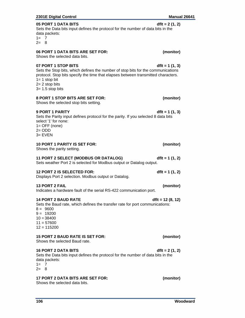
2301E Digital Control Manual 26641
106 Woodward
05 PORT 1 DATA BITS dflt = 2 (1, 2) Sets the Data bits input defines the protocol for the number of data bits in the data packets: 1= 7 2= 8 06 PORT 1 DATA BITS ARE SET FOR: (monitor) Shows the selected data bits. 07 PORT 1 STOP BITS dflt = 1 (1, 3) Sets the Stop bits, which defines the number of stop bits for the communications protocol. Stop bits specify the time that elapses between transmitted characters. 1= 1 stop bit 2= 2 stop bits 3= 1.5 stop bits 8 PORT 1 STOP BITS ARE SET FOR: (monitor) Shows the selected stop bits setting. 9 PORT 1 PARITY dflt = 1 (1, 3) Sets the Parity input defines protocol for the parity. If you selected 8 data bits select '1' for none: 1= OFF (none) 2= ODD 3= EVEN 10 PORT 1 PARITY IS SET FOR: (monitor) Shows the parity setting. 11 PORT 2 SELECT (MODBUS OR DATALOG) dflt = 1 (1, 2) Sets weather Port 2 is selected for Modbus output or Datalog output. 12 PORT 2 IS SELECTED FOR: dflt = 1 (1, 2) Displays Port 2 selection. Modbus output or Datalog. 13 PORT 2 FAIL (monitor) Indicates a hardware fault of the serial RS-422 communication port. 14 PORT 2 BAUD RATE dflt = 12 (8, 12) Sets the Baud rate, which defines the transfer rate for port communications: 8 = 9600 9 = 19200 10 = 38400 11 = 57600 12 = 115200 15 PORT 2 BAUD RATE IS SET FOR: (monitor) Shows the selected Baud rate. 16 PORT 2 DATA BITS dflt = 2 (1, 2) Sets the Data bits input defines the protocol for the number of data bits in the data packets: 1= 7 2= 8 17 PORT 2 DATA BITS ARE SET FOR: (monitor) Shows the selected data bits.
Manual 26641 2301E Digital Control
Woodward 107
18 PORT 2 STOP BITS dflt = 1 (1, 3) Sets the Stop bits, which defines the number of stop bits for the communications protocol. Stop bits specify the time that elapses between transmitted characters. 1= 1 stop bit 2= 2 stop bits 3= 1.5 stop bits 19 PORT 2 STOP BITS ARE SET FOR: (monitor) Shows the selected stop bits setting. 20 PORT 2 PARITY dflt = 1 (1, 3) Sets the Parity input defines protocol for the parity. If you selected 8 data bits select '1' for none: 1= OFF (none) 2= ODD 3= EVEN 21 PORT 2 PARITY IS SET FOR: (monitor) Shows the parity setting. 22 PORT 2 TIME OUT (SEC) dflt = 2.000 (0.00, 100.00) Sets the Time-out Number of Seconds input defines the Modbus link dead time allowed before a link error occurs. 23 PORT 2 ADDRESS dflt = 1 (1, 247) Sets the Network Address input defines the slave block address on the Modbus network. The network address may depend on master device allowable addresses. 24 REMOTE SPEED DIVIDE dflt = FALSE (TRUE, FALSE) Sets a switch so that the Modbus Address Analog Write 4:0002 can be multiplied on the HMI end for better resolution. If this value is TRUE, send a 9000 for an engine speed of 900. If this value is FALSE, send a 900 for an engine speed of 900. 25 PORT 2 LINK ERROR (monitor) Will indicate a TRUE when the slave device fails to answer a data request in a specified number of time-out seconds. 26 PORT 2 EXCEPTION ERROR (monitor) Will indicate a TRUE when an exception error such as “illegal command” is detected. 27 PORT 2 TOTAL EXCEPTION ERRORS (monitor) Is a count of the total exception errors. 28 ENABLE ANALOG INPUT W/MODBUS dflt = FALSE (TRUE, FALSE) This variable when set to TRUE will allow an analog input to be used as a Remote Speed Reference, while using Modbus to control all of the other functions. When the value is FALSE, Modbus can be used to control the Speed Reference.
Saving the Tunable Values When done with the tuning procedure, make sure that they are saved in the
control. This is accomplished by clicking on the “Save” icon. Failure to do this might cause the control to reset back to the default numbers.
2301E Digital Control Manual 26641
108 Woodward
Chapter 5. Initial Control Settings
Initial Prestart Settings
Read this entire procedure before starting the prime mover.
1. RATED SPEED—Set to Generator synchronous speed. 2. Set the correct number of gear teeth in “Enter number of gear teeth”. 3. Select the proper speed function. 4. Set the overspeed setting, usually 110 to 115% of the rated speed. Make
sure that there is always a separate overspeed detection device to protect the engine form overspeed!
5. For initial startup, configure the control for single slope gain dynamics. Turn off DYNAMICS 2, use only Dynamics 1 adjustments for initial startup.
6. IDLE PROP GAIN – Set at 1.0 7. RATED PROP GAIN 1—Set at 2.0. 8. RESET 1—Set at 1.0. 9. ACTUATOR COMPENSATION 1—Set the ACTUATOR COMPENSATION at
0.1 for diesel or fuel injected gasoline prime movers. Set the ACTUATOR COMPENSATION at 0.35 for carbureted gas or gasoline prime movers.
10. Set GAIN RATIO 1 to 1.0 to disable the effect of window width and gain ratio. 11. ACCEL RAMP TIME—Set at 20 sec. DECEL RAMP TIME—Set at 20 sec. 12. LOW IDLE SPEED—Set at idle speed rpm, (no lower than 20% of rated). 13. LOAD GAIN—Set at 1.0, or the value of other load sharing controls on a
common bus. 14. DROOP—Set at desired percentage. 15. START FUEL LIMIT—Set at 100%. 16. Be sure the actuator is connected to terminals 13 and 14 and the speed
signal connected to terminals 25 and 26.
Start-up Adjustments 1. Complete the Configuration Procedure in Chapter 4, and the initial prestart
settings above.
Be sure the Rated Speed and Number of Teeth are set correctly for your application as described earlier in this chapter.
2. Close the Close For Rated contact. Set the control for isochronous operation
by closing the droop/CB Auxiliary and the generator Load contact.
This is for initial prime mover start-up only. For normal start-up, the Close for Rated contact (open for idle/close for rated) should be open if the prime mover is to start at idle.
3. Apply input power to the control.
Manual 26641 2301E Digital Control
Woodward 109
4. Preset rated speed (optional). When using a signal generator to verify the proper configuration setting: set
the signal generator for the frequency of the speed sensor at rated speed, and connect it to terminals 25 and 26. (The rated speed frequency in Hz equals the rated prime mover speed in rpm times the number of teeth on the speed sensing gear divided by 60.) Put the Close For Rated contact in the rated (closed) position. Connect a dc analog voltmeter to terminals 13(+) and 14(–) to read actuator voltage. If the actuator voltage is at minimum (minimum will be approximately 0 volts), slowly decrease the input frequency (increase for reverse acting controls) until the voltage just begins to move to maximum. If the actuator voltage is at maximum, slowly increase the input frequency (decrease for reverse-acting controls) until the voltage just begins to move to minimum. Continue to very slowly adjust the input frequency in the appropriate direction, trying to stop the actuator voltage between the minimum and maximum voltages. Because it is not possible to stop the motion, cease adjusting when the voltage changes slowly. The RATED SPEED configuration has been verified. No further adjustment when the engine is running will be necessary.
5. Check the speed sensor. Minimum voltage required from the speed sensor to operate the electronic
control is 1.0 Vrms, measured at cranking speed or the lowest controlling speed. For this test, measure the voltage while cranking, with the speed sensor connected to the control. Before cranking, be sure to prevent the prime mover from starting. The frequency required to clear the Loss of Speed shutdown is entered as a percent of rated speed during configuration. For example, at 5% of 1800 rpm rated speed, the failed speed sensing circuit is cleared at 90 rpm.
Be prepared to make an emergency shutdown when starting the engine, turbine, or other type of prime mover, to protect against runaway or overspeed with possible personal injury, loss of life, or property damage.
6. Start the prime mover.
Adjust for Stable Operation If prime mover operation is stable, go to the “Speed Setting Adjustment” procedure. If the prime mover is hunting at a rapid rate, slowly decrease the GAIN until performance is stable. If the prime mover is hunting at a slow rate, increase the RESET until the prime mover stabilizes. If increasing the RESET does not stabilize the prime mover, it also may be necessary to either: Slowly decrease the GAIN or Slowly decrease the GAIN and increase the ACTUATOR COMPENSATION. For the PID adjustment see Chapter 6, Alternate Dynamic Adjustments.
2301E Digital Control Manual 26641
110 Woodward
Dynamic Adjustment The object of the PROPORTIONAL GAIN, RESET, and ACTUATOR COMPENSATION adjustment is to obtain the optimum, or desired, stable prime mover speed response. Connect a dc analog voltmeter to terminals 13(+) and 14(–) to monitor the actuator voltage. Increasing the setting of the GAIN to provides faster transient response (decreases the magnitude of the speed change from a sudden change in load). To achieve optimum response, slowly increase the GAIN until the voltage on the voltmeter becomes slightly unstable, then slowly lower the GAIN as necessary to stabilize the meter reading. Step load the generator, bump the actuator terminal shaft, or use the software “Bump Act Trigger (T then F)”in the dynamics tuning sections, to make sure that the prime mover returns to the proper speed with little overshoot or undershoot of the speed setting. To reduce overshoot, increase the RESET. If the prime mover is slow in returning to the proper speed, decrease the RESET.
Actuator Compensation Adjustment If the ACTUATOR COMPENSATION is set as described under Initial Prestart Settings, no further adjustment is normally required. If a slow periodic instability remains, slightly increase the ACTUATOR COMPENSATION, and repeat the GAIN and RESET adjustments. Continue to increase the ACTUATOR COMPENSATION and readjust the GAIN and RESET until stability is achieved. If a fast instability or extremely active actuator is evident, slightly decrease the ACTUATOR COMPENSATION. If necessary, the ACTUATOR COMPENSATION may be set to .01. This may be required when engine torsionals cause excessive fuel-linkage movement.
Ramp Time Adjustment Adjust the ACCEL RAMP TIME to achieve satisfactory prime mover acceleration to rated speed with minimum overshoot. The number entered is the time in seconds to change speed from idle to rated. Adjust the DECEL RAMP TIME to achieve satisfactory prime mover deceleration to idle speed with minimum undershoot. The number entered is the time in seconds to change speed from rated to idle.
Raise/Lower Time Adjustment Adjust the RAISE SPEED TIME to achieve satisfactory prime mover acceleration toward the raise speed limit with minimum overshoot. The number entered is the time in seconds to change speed from LOWER SPEED LIMIT to RAISE SPEED LIMIT. Adjust the LOWER SPEED TIME to achieve satisfactory prime mover deceleration toward the lower limit with minimum undershoot. The number entered is the time in seconds to change speed from RAISE SPEED LIMIT to LOWER SPEED LIMIT.
Manual 26641 2301E Digital Control
Woodward 111
Start Fuel Limit Adjustment With the prime mover operating at rated speed and no load, note the Fuel Demand % displayed on the HMI. Set the Start Fuel Level 10% higher than the fuel demand noted above. Shut down the prime mover. Start the prime mover and observe the start time, overshoot of speed setting, and smoke emissions obtained. The Start Fuel Limit may be adjusted as required to optimize the prime mover starting characteristics. When the prime mover start is initiated the fuel is set to the start fuel limit, the fuel level is then increased at the rate set by Start Ramp Rate (%FD/Sec). The fuel-limiting function is turned off automatically when the speed control takes over.
For prime movers not requiring start fuel limiting, the START FUEL LIMIT function can be deactivated by setting the Start Fuel Limit to 110%.
Speed Sensor Check Measure the voltage across terminals 25 and 26 to be sure there is a minimum of 1.0 Vrms at cranking speed, and a maximum of 25 Vrms at rated speed. If the voltage exceeds 25 Vrms, increase the gap of the speed sensor, and be sure that there is still a minimum of 1.0 Vrms at cranking speed.
Current Transformer (CT) Phasing Check
This control contains internal current transformers. Due to their low impedance, shorting their inputs is not effective. The current input must be removed from the control and shorted externally.
HIGH VOLTAGE—Never disconnect any wire attached to load sensor terminals 4 through 9 when the prime mover is running unless temporary 0.5 A, 20 W resistors are installed as shown in Figure 5-1, and all load is removed. The current transformers can develop dangerously high voltages when open circuited while the prime mover is running.
1. Go to the T**KW INPUT CALIBRATION** sheet and observe 03 Gen
Output (read KW) , and LOAD SIGNAL OUT to measure the load sensor output. The displayed values are not yet calibrated to read Kilowatts, but is used here for indication.
2. Start the prime mover. With the generator operating in the isochronous mode and not paralleled, load the generator to as near to full load as possible.
3. Use a clamp-on ammeter and measure the per phase current of the Current transformer output. Check that current in each of the three CTs are equal. In a balanced three phase system the Load Signal Out reading will be approximately:
Load Signal Out = kW Input Calibration Gain X 0.1 X Amps (RMS reading of
one phase) A clamp-on ammeter is recommended to eliminate the need to open CT
wiring to insert an ammeter in series with the CT output.
2301E Digital Control Manual 26641
112 Woodward
4. If the Load Signal Out Reading is within 10% of the above calculation, the PT/CT phasing is correct. If the phasing is incorrect, proceed to the Phase Correction Procedure. If the phasing appears correct, skip the Phase Correction Procedure and go to the Load Calibration Adjustment procedure.
If after completing the LOAD SENSOR CALIBRATION and DROOP adjustments, the control loading is extremely sensitive to changes in the power factor when operating in parallel, complete the phase correction procedure.
The most accurate calibration is made at full load. However, if it is not possible to run the generator set at full load, run it at less than full load, and reduce the voltage reading given in this calibration procedure proportionally. For example: run a 200 kW generator set at 100 kW and divide all voltages given in this calibration procedure by 2. If you reduce the load in this manner, be sure to reduce it by the same amount throughout the calibration procedure.
Phase Correction Procedure
This procedure requires a minimum power factor of (.9). If a .9 power factor cannot be obtained, tracing through the wiring is the only means of correcting the current transformer phasing.
The highest positive reading of kW or Load Signal Out will be obtained when the CTs are correctly matched to the load sensor terminals in both phase and polarity. The following procedure will assure the correct connection of the current transformers. It is required only if the phasing check indicates incorrect phasing, or loading stability is extremely sensitive to the power factor. Make trial connections of the first CT to all three load sensor inputs, polarized both ways (a total of six connections). Record the Load Signal Out reading for each connection. Connect the first CT to the terminals that produce the highest positive reading, and with the polarity that produces the highest positive voltage. The displayed Load Gain reading is limited to about 0.2, therefore a negative reading indicates a phasing or polarity error. Try the second CT on each of the remaining two CT input terminals, in each polarity, and record the Load Signal Out reading. Connect the second CT to the terminals that produce (and with the polarity that produces) the highest positive reading. Try the last CT on the remaining input terminals, polarized both ways, and record the voltage. Connect the last CT in the polarity that produces the highest Load Signal Out reading.
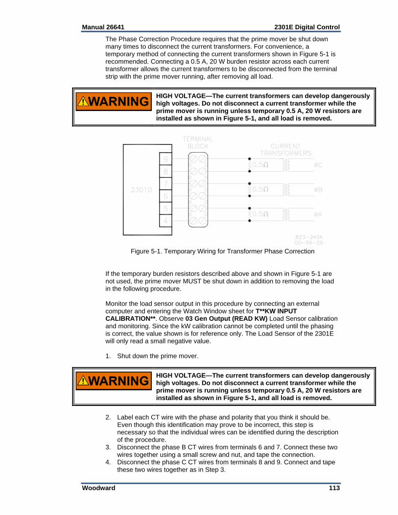
Manual 26641 2301E Digital Control
Woodward 113
The Phase Correction Procedure requires that the prime mover be shut down many times to disconnect the current transformers. For convenience, a temporary method of connecting the current transformers shown in Figure 5-1 is recommended. Connecting a 0.5 A, 20 W burden resistor across each current transformer allows the current transformers to be disconnected from the terminal strip with the prime mover running, after removing all load.
HIGH VOLTAGE—The current transformers can develop dangerously high voltages. Do not disconnect a current transformer while the prime mover is running unless temporary 0.5 A, 20 W resistors are installed as shown in Figure 5-1, and all load is removed.
Figure 5-1. Temporary Wiring for Transformer Phase Correction
If the temporary burden resistors described above and shown in Figure 5-1 are not used, the prime mover MUST be shut down in addition to removing the load in the following procedure. Monitor the load sensor output in this procedure by connecting an external computer and entering the Watch Window sheet for T**KW INPUT CALIBRATION**. Observe 03 Gen Output (READ KW) Load Sensor calibration and monitoring. Since the kW calibration cannot be completed until the phasing is correct, the value shown is for reference only. The Load Sensor of the 2301E will only read a small negative value. 1. Shut down the prime mover.
HIGH VOLTAGE—The current transformers can develop dangerously high voltages. Do not disconnect a current transformer while the prime mover is running unless temporary 0.5 A, 20 W resistors are installed as shown in Figure 5-1, and all load is removed.
2. Label each CT wire with the phase and polarity that you think it should be.
Even though this identification may prove to be incorrect, this step is necessary so that the individual wires can be identified during the description of the procedure.
3. Disconnect the phase B CT wires from terminals 6 and 7. Connect these two wires together using a small screw and nut, and tape the connection.
4. Disconnect the phase C CT wires from terminals 8 and 9. Connect and tape these two wires together as in Step 3.
2301E Digital Control Manual 26641
114 Woodward
5. Connect the two wires from the phase A CT to the phase A input terminals 4 and 5.
6. Start the prime mover, apply full load, and monitor the load sensor output. Start a list and record this value.
7. Unload the system and reverse the phase A CT wires on terminals 4 and 5.* 8. Apply full load, monitor the load sensor, and record this value. 9. Unload the system, remove phase A CT wires from terminals 4 and 5, and
connect them to phase B input terminals 6 and 7.* 10. Apply full load, monitor the load sensor, and record this value. 11. Unload the system and reverse the phase A CT wires on terminals 6 and 7.* 12. Apply full load, monitor the load signal, and record this value. 13. Unload the system, remove phase A CT wires from terminals 6 and 7, and
connect them to phase C input terminals 8 and 9.* 14. Apply full load, monitor the load sensor, and record this value. 15. Unload the system and reverse the phase A CT wires on terminals 8 and 9.* 16. Apply full load, measure the load signal, and record this reading. 17. Unload the system and compare the six readings taken.* 18. Remove the phase A CT wires from terminal 8 and 9 and connect the phase
A wires to the pair of terminals that produced the highest positive load value and in the polarity that produced the highest positive load value.
19. Untape and disconnect the phase B CT wires. Connect the phase B CT wires to one pair of the two remaining pairs of CT input terminals on the load sensor.
20. Apply full load and measure the load signal. Start a new list and record this reading.
21. Unload the system, and reverse the phase B CT wires on the same terminals.*
22. Apply full load, measure the load signal, and record this reading. 23. Unload the system, remove phase B CT wires, and connect them to the other
pair of terminals.* 24. Apply full load, measure the load signal, and record this reading. 25. Unload the system and reverse phase B CT wires on the same terminals.* 26. Apply full load and measure the load signal. Record this reading, and
compare the four readings on the list. 27. Unload the system. Remove the phase B CT wires and connect them to the
pair of CT input terminals that produced the highest positive load signal reading and with the polarity that produced the highest positive load signal reading.*
28. Untape and disconnect the phase C CT wires. Connect these two wires to the remaining pair of CT input terminals.
29. Apply full load, measure the load signal, and record this reading. 30. Unload the system and reverse the phase C CT wires on the same
terminals.* 31. Apply full load, measure the load signal, and record this reading. 32. Unload and shut down the system. Compare the two readings.* 33. Connect the phase C CT wires to the same pair of CT input terminals, but in
the polarity that produced the highest positive load signal reading. 34. Re-label each wire with the phase designation of the terminal that it is now
connected to. 35. Remove the burden resistors and terminal block.

Manual 26641 2301E Digital Control
Woodward 115
Load Calibration Adjustment For this procedure, the generator must be running isochronously and not paralleled. Start the prime mover and apply full load. With the Watch Window at T**KW INPUT CALIBRATION**, observe 05 GENOUTPUT (KW). If this reading does not match external instrumentation, adjust calibration gain and offset until Watch Window value matches metering. The values should match at all intermediate points.
If values at full load (or a lower reading proportional to a load less than 100%) cannot be obtained, and the phasing has been checked and is correct, the current transformers are probably the wrong size. The current-transformer output must be from 3 to 7 A (5 A nominal) at full load.
When paralleled in isochronous mode or on an isolated bus, generator speeds must be the same. If speed references are not equal, load sharing will not remain proportional as the load varies. Any difference in loads between the units can be corrected by adjusting the Load Gain. Increasing the LOAD GAIN will cause that generator to carry less load. If stability problems occur when paralleled at a particular load signal reading, reduce the reading by reducing the LOAD GAIN, and reduce the load signal reading setting of all other generators in the system to the same reading. When the load signal readings of all generators in a system are reduced, the load sharing gain will be reduced and this may result in some loss of load sharing sensitivity. It may be necessary to reduce the load signal reading of each unit in the system to as low as 3 volts in cases of extremely poor system dynamics. If your system requires a load signal reading as low as 3 volts, consult Woodward for suggestions for possible remedies.
Droop Adjustment Because of the calculation available in the control, the droop percentage entered will result in the correct speed change if the KW sensor is properly calibrated. The droop percent is automatically corrected for load gain voltage values. The speed trim range can be configured to stop the speed reference at 100% load, or if a F reference source is used its range can be set to give no load to full load limits.
Figure 5-2. Droop Adjustment
2301E Digital Control Manual 26641
116 Woodward
Chapter 6. Alternate Dynamic Adjustments
Introduction This procedure, based on the Zeigler-Nichols Method, is an empirical method to find first-pass settings for gain, reset, and actuator compensation in a PID controller. First, the controller is set up to act as a proportional-only controller by removing the effect of the reset and actuator compensation terms. The system is then bumped and the resulting response is examined. Gain is slowly increased until the point of marginal stability is found. Once that point is found, some calculations are done using the period of oscillation and the gain value. The results of the calculations are gain, reset, and actuator compensation that can be plugged into the control. This procedure has been used to find a good set of initial settings for the PID controller. This section also describes adjusting some other parameters to improve on the initial settings.
Adjustment Setup 1. Complete the start-up adjustments described in Chapter 5, Initial Control
Settings. The engine should now be somewhat stable. The settings should also be saved to EEPROM.
2. Copy the settings you have right now from 1st dynamics to 2nd dynamics. Save these values to EEPROM. As you go through the following steps, you will be trying to find the point of marginal stability. That means that you will be very close to the point of instability. You are likely to adjust the gain a little bit too far and go into an unstable condition. When that happens, you will see the engine start to run away and approach overspeed or stall. The reason the dynamic settings are copied from 1st dynamics to 2nd dynamics is to allow you to quickly switch to settings that can control the engine and keep it from running away or dying. We recommend you use either a jumper or a switch to allow you to quickly select 2nd dynamics as you are performing this procedure so that you are confident you always have the ability to control the engine speed.
3. Connect a chart recorder to record engine speed. Analog output 1 default configuration provides a 4–20 mA signal proportional to engine speed. If necessary, set the CFIG ANALOG OUTPUTS to read engine speed on another configurable analog output if analog output 1 is being used for something else.
4. Enable slight Firing Torsional Filtering by setting the SPEED FILTER frequency at 15.8 Hz. This setting is found in the Dynamics service menu. A lower setting may be necessary if firing torsionals are exceptionally high due to combustion instability, etc. However, a setting below 10 Hz is not recommended.
Gain, Reset, and Actuator Compensation Adjustments 5. The engine should now be running at no load, idle speed. Start the chart
recorder. Remember, when doing any of these adjustments, you can get the engine back to running stable by switching in the 2nd dynamics. Select 1st dynamics now. Reduce the gain by 50%.
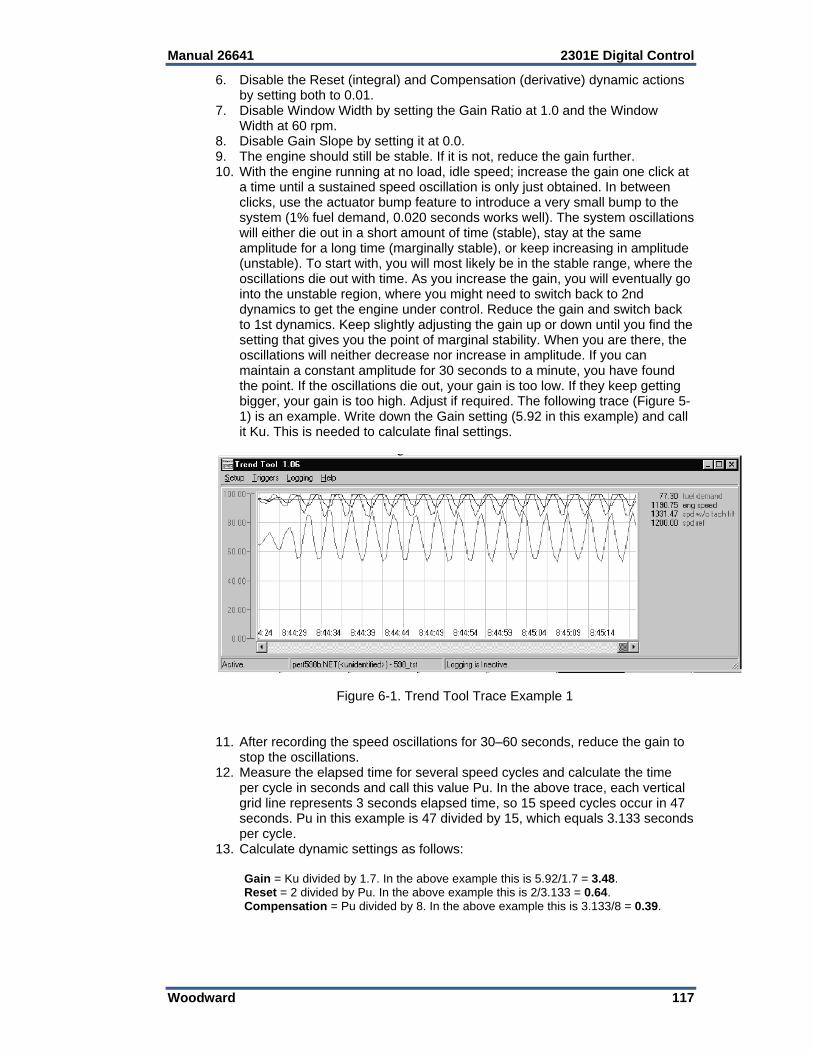
Manual 26641 2301E Digital Control
Woodward 117
6. Disable the Reset (integral) and Compensation (derivative) dynamic actions by setting both to 0.01.
7. Disable Window Width by setting the Gain Ratio at 1.0 and the Window Width at 60 rpm.
8. Disable Gain Slope by setting it at 0.0. 9. The engine should still be stable. If it is not, reduce the gain further. 10. With the engine running at no load, idle speed; increase the gain one click at
a time until a sustained speed oscillation is only just obtained. In between clicks, use the actuator bump feature to introduce a very small bump to the system (1% fuel demand, 0.020 seconds works well). The system oscillations will either die out in a short amount of time (stable), stay at the same amplitude for a long time (marginally stable), or keep increasing in amplitude (unstable). To start with, you will most likely be in the stable range, where the oscillations die out with time. As you increase the gain, you will eventually go into the unstable region, where you might need to switch back to 2nd dynamics to get the engine under control. Reduce the gain and switch back to 1st dynamics. Keep slightly adjusting the gain up or down until you find the setting that gives you the point of marginal stability. When you are there, the oscillations will neither decrease nor increase in amplitude. If you can maintain a constant amplitude for 30 seconds to a minute, you have found the point. If the oscillations die out, your gain is too low. If they keep getting bigger, your gain is too high. Adjust if required. The following trace (Figure 5-1) is an example. Write down the Gain setting (5.92 in this example) and call it Ku. This is needed to calculate final settings.
Figure 6-1. Trend Tool Trace Example 1 11. After recording the speed oscillations for 30–60 seconds, reduce the gain to
stop the oscillations. 12. Measure the elapsed time for several speed cycles and calculate the time
per cycle in seconds and call this value Pu. In the above trace, each vertical grid line represents 3 seconds elapsed time, so 15 speed cycles occur in 47 seconds. Pu in this example is 47 divided by 15, which equals 3.133 seconds per cycle.
13. Calculate dynamic settings as follows: Gain = Ku divided by 1.7. In the above example this is 5.92/1.7 = 3.48. Reset = 2 divided by Pu. In the above example this is 2/3.133 = 0.64. Compensation = Pu divided by 8. In the above example this is 3.133/8 = 0.39.
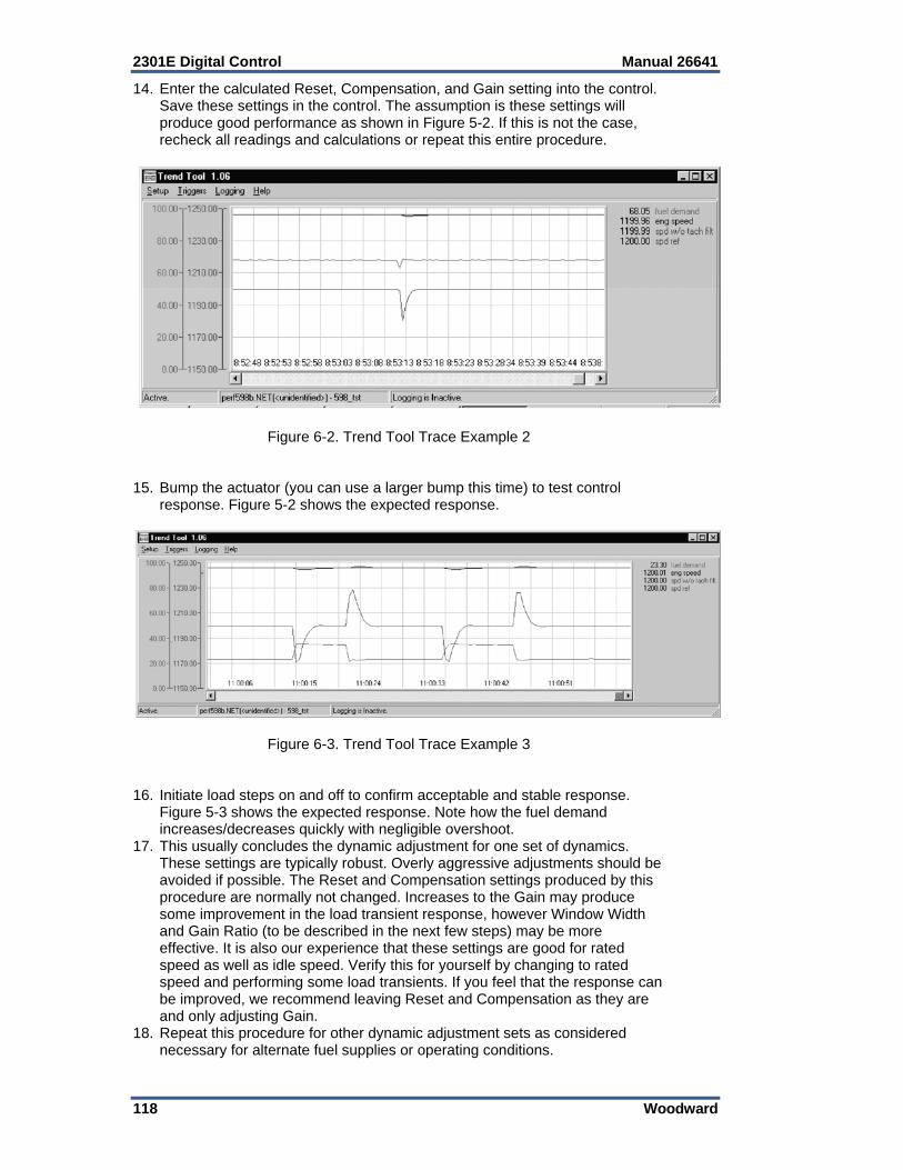
2301E Digital Control Manual 26641
118 Woodward
14. Enter the calculated Reset, Compensation, and Gain setting into the control. Save these settings in the control. The assumption is these settings will produce good performance as shown in Figure 5-2. If this is not the case, recheck all readings and calculations or repeat this entire procedure.
Figure 6-2. Trend Tool Trace Example 2 15. Bump the actuator (you can use a larger bump this time) to test control
response. Figure 5-2 shows the expected response.
Figure 6-3. Trend Tool Trace Example 3 16. Initiate load steps on and off to confirm acceptable and stable response.
Figure 5-3 shows the expected response. Note how the fuel demand increases/decreases quickly with negligible overshoot.
17. This usually concludes the dynamic adjustment for one set of dynamics. These settings are typically robust. Overly aggressive adjustments should be avoided if possible. The Reset and Compensation settings produced by this procedure are normally not changed. Increases to the Gain may produce some improvement in the load transient response, however Window Width and Gain Ratio (to be described in the next few steps) may be more effective. It is also our experience that these settings are good for rated speed as well as idle speed. Verify this for yourself by changing to rated speed and performing some load transients. If you feel that the response can be improved, we recommend leaving Reset and Compensation as they are and only adjusting Gain.
18. Repeat this procedure for other dynamic adjustment sets as considered necessary for alternate fuel supplies or operating conditions.
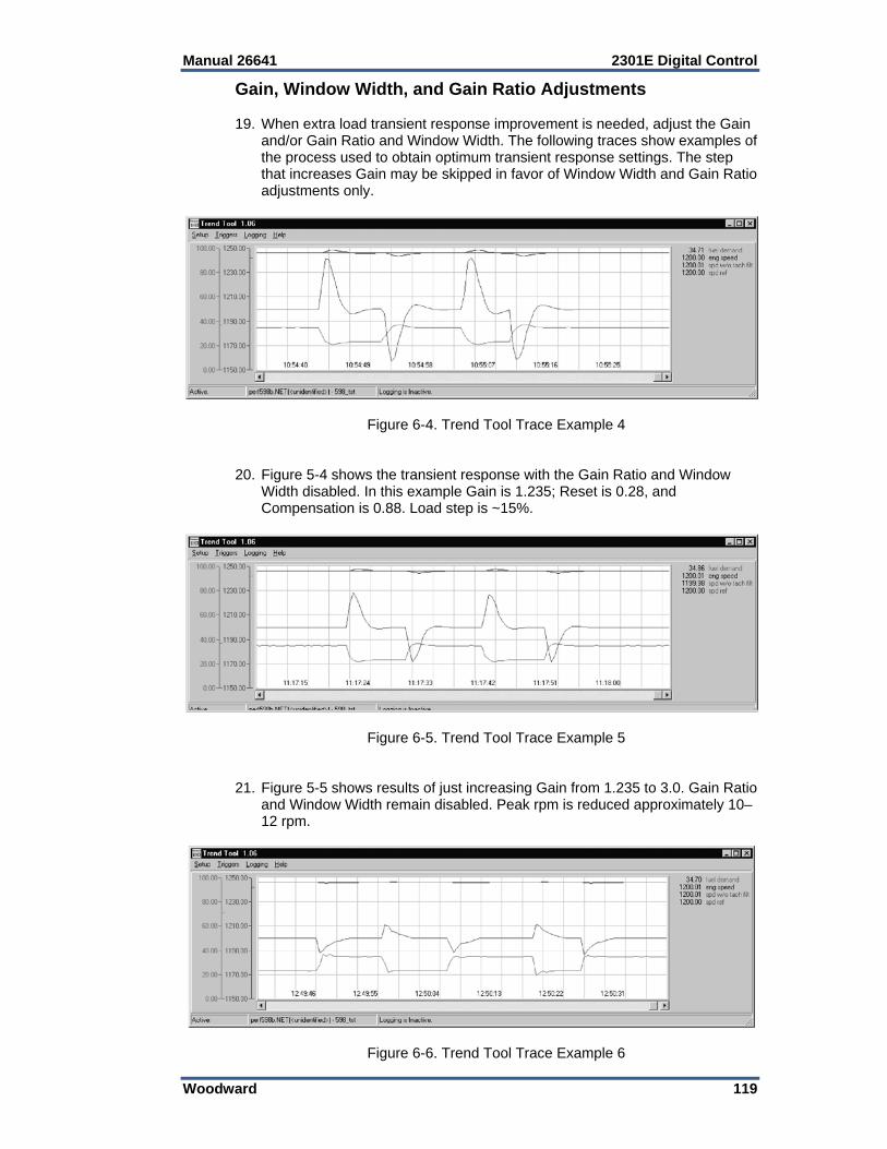
Manual 26641 2301E Digital Control
Woodward 119
Gain, Window Width, and Gain Ratio Adjustments 19. When extra load transient response improvement is needed, adjust the Gain
and/or Gain Ratio and Window Width. The following traces show examples of the process used to obtain optimum transient response settings. The step that increases Gain may be skipped in favor of Window Width and Gain Ratio adjustments only.
Figure 6-4. Trend Tool Trace Example 4 20. Figure 5-4 shows the transient response with the Gain Ratio and Window
Width disabled. In this example Gain is 1.235; Reset is 0.28, and Compensation is 0.88. Load step is ~15%.
Figure 6-5. Trend Tool Trace Example 5 21. Figure 5-5 shows results of just increasing Gain from 1.235 to 3.0. Gain Ratio
and Window Width remain disabled. Peak rpm is reduced approximately 10–12 rpm.
Figure 6-6. Trend Tool Trace Example 6

2301E Digital Control Manual 26641
120 Woodward
22. Figure 5-6 shows results of ultimately increasing Gain Ratio from 1.0 to 3.0 and decreasing Window Width from 60 rpm to 5 rpm. Overall peak rpm has been reduced approx 30 rpm. The fuel demand is steeper with little overshoot and roll-off. The speed roll-off is extended slightly by the Window Width and Gain Ratio settings. This is normal.
23. Begin the Window Width and Gain Ratio adjustment process by increasing the Gain Ratio from 1.0 to 2.0, then reduce the Window Width from 60 rpm in 10-rpm increments. Actuate an actuator bump or load on and load off step after each adjustment and observe the change in peak engine speed. Initially, the window will be too wide to cause any change in peak speed. Eventually a reduction will be observed. Be prepared to first reduce the Gain Ratio, or second increase the Window Width, if severe instability occurs due to cycling through the low gain region. Do not attempt smaller Window Width settings if this occurs. It may be useful to set the alternate (1st or 2nd) dynamics to produce a stable engine speed and to switch to these dynamics should severe instability occur while setting Gain Ratio and Window Width. Otherwise, continue the Window Width reduction and actuator bump response down to 10 rpm, and then reduce to 5 rpm. Reductions below 5 rpm are not recommended. Increase the Gain Ratio as needed to obtain the desired response. The objective is to set the smallest Window Width with the highest Gain Ratio without going unstable. If the Gain Ratio setting that causes severe instability is known, then the final setting should not be more than half of this amount.
24. Eventually a point is reached where no further improvement is possible. The fuel demand overshoot should be minimal. Reduce the Gain or Gain Ratio as needed to reduce the fuel demand overshoot.
Gain Slope and Gain Breakpoint Adjustments 25. Gain Slope is an adjustment that increases gain as load (fuel demand)
increases. This adjustment should not be changed from 0.0 until the previously described adjustments have been made. While it is possible to set a negative Gain Slope which decreases gain as load increases, it is considered unnecessary and not recommended.
26. The objective of these adjustments is to add gain at high engine loads to improve transient load response. If the transient load response is already acceptable, no adjustments are needed. Otherwise proceed as follows:
27. Set the Gain Breakpoint equal to the no-load minimum speed fuel demand. The actual fuel demand minus the Gain Breakpoint setting is multiplied by the Gain Slope to add gain when load increases. When the actual fuel demand is at no-load, the difference is zero, therefore zero gain is added at no-load.
28. Set Gain Slope while the engine is operating at or near rated load. Gradually increase the Gain Slope in 0.5 increments, and bump the actuator or make a step load change to measure the transient response. Continue this process until the desired transient load response is achieved or excessive instability occurs. Should excessive instability occur, reduce the setting to one-half of the setting that produced this instability.
Manual 26641 2301E Digital Control
Woodward 121
Chapter 7. Troubleshooting
Introduction The following troubleshooting guide is an aid in isolating trouble to the control box, actuator, plant wiring, or elsewhere. Troubleshooting beyond this level is recommended ONLY when a complete facility for control testing is available.
The control can be damaged with the wrong voltage. When replacing a control, check the power supply, battery, etc., for the correct voltage.
Troubleshooting Procedure This chapter is a general guide for isolating system problems. The guide assumes that the system wiring, soldering connections, switch and relay contacts, and input and output connections are correct and in good working order. Make the checks in the order indicated. Various system checks assume that the prior checks have been properly done.
Be prepared to make an emergency shutdown when starting the engine, turbine, or other type of prime mover, to protect against runaway or overspeed with possible personal injury, loss of life, or property damage.
Control Start-up When the control is powered on, the CPU begins execution of a section of the software program known as the boot code. This code performs hardware diagnostics and checks that a valid application program has been installed. During this period all control outputs will remain disabled. The boot code takes approximately 1.5 seconds to execute. During this period the red status LED should be red. When execution of the boot code has completed, control will be transferred to the application program. When the application program begins, the control outputs will be enabled and system control will begin. At that point the red status LED will be turned green and should remain on as long as the control is running. If the control fails its self-test diagnostics during boot, fails its on-line self-tests while running the application program, or fails in any other way that it can detect, then the CPU will blink the red status LED to indicate the failure. If the CPU LED is blinking, the unit has failed and needs to be returned.
To prevent damage to the prime mover, the prime mover must be shut down for all system checks.
2301E Digital Control Manual 26641
122 Woodward
Control Test and Calibration General Do the following checks on the 2301E control. Then verify the functioning of set points and adjustments. 1. Connect a computer to the communication port. Start the Control Assistant
Software or the 2301E Toolkit Service Tool in accordance with the instructions in Chapter 4. Verify that correct voltage and polarity are applied to the control.
2. Select the 1st Dynamics Menu. Verify that all set points are as recorded during installation. Repeat for the other menus. If any differences are found, change the set point(s) to the correct value. Click the “SAVE VALUES” icon on the Tool bar. Remove power from the control for at least 10 seconds. Verify correct values were retained during power down. Failure indicates the control has failed and should be replaced.
Discrete Inputs Do the following test to verify the function of the discrete inputs. Do NOT do this test with the engine running. 1) Repeat this step for all discrete inputs. Close the appropriate input. The
status in DISPLAY DIGITAL I/O should switch from OPEN to CLOSED. If the value does not change when the contact is closed, the control has failed and should be replaced.
Discrete Outputs To Verify operation of the Discrete Outputs, go to the Service: S**RELAY AND ANOUT TESTS** menu. With the engine shut down, enable the manual driver test. From this menu , each discrete output may be activated and its operation verified. If the output is activated, the same voltage as applied at terminal 42 and 43 should be measured between terminal 42 and the appropriate output terminal (44–47). Testing of the internal CB Aux relay may be done by observing the green LED near terminal 9 and 10. The manual relay test must be disabled (status “test off”) or the control will hold the actuator current to minimum.
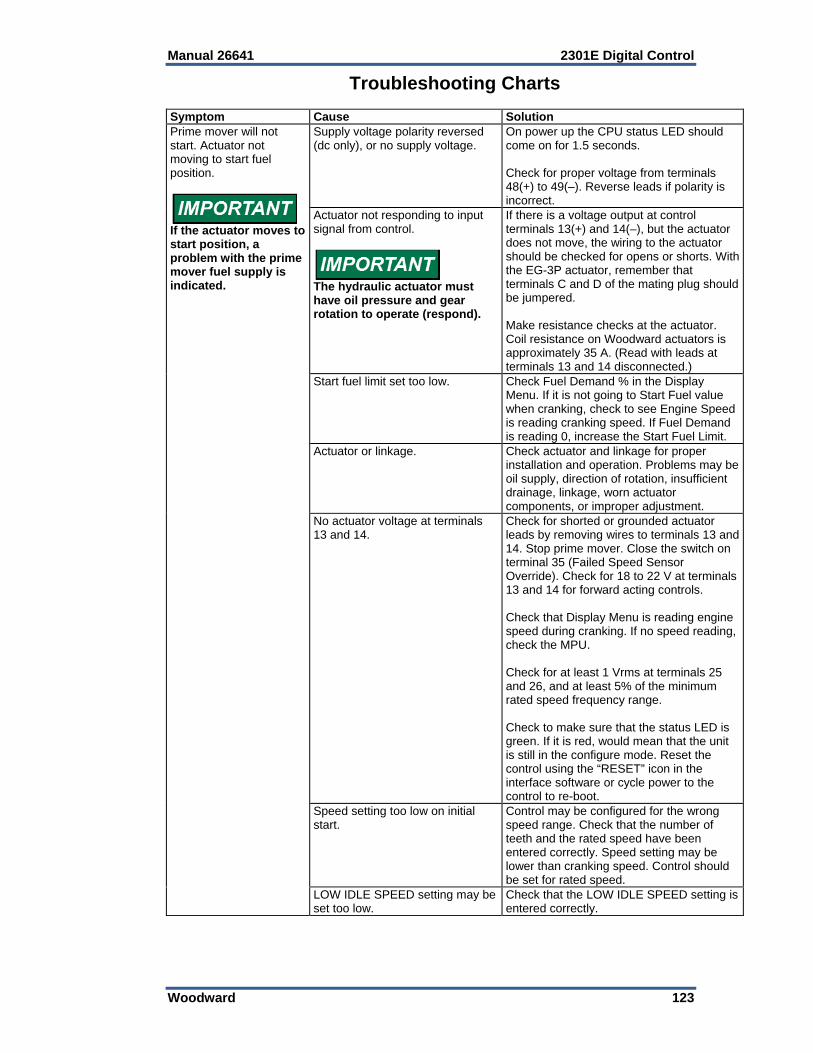
Manual 26641 2301E Digital Control
Woodward 123
Troubleshooting Charts
Symptom Cause SolutionPrime mover will not start. Actuator not moving to start fuel position.
If the actuator moves to start position, a problem with the prime mover fuel supply is indicated.
Supply voltage polarity reversed (dc only), or no supply voltage.
On power up the CPU status LED should come on for 1.5 seconds. Check for proper voltage from terminals 48(+) to 49(–). Reverse leads if polarity is incorrect.
Actuator not responding to input signal from control.
The hydraulic actuator must have oil pressure and gear rotation to operate (respond).
If there is a voltage output at control terminals 13(+) and 14(–), but the actuator does not move, the wiring to the actuator should be checked for opens or shorts. With the EG-3P actuator, remember that terminals C and D of the mating plug should be jumpered. Make resistance checks at the actuator. Coil resistance on Woodward actuators is approximately 35 A. (Read with leads at terminals 13 and 14 disconnected.)
Start fuel limit set too low. Check Fuel Demand % in the Display Menu. If it is not going to Start Fuel value when cranking, check to see Engine Speed is reading cranking speed. If Fuel Demand is reading 0, increase the Start Fuel Limit.
Actuator or linkage. Check actuator and linkage for proper installation and operation. Problems may be oil supply, direction of rotation, insufficient drainage, linkage, worn actuator components, or improper adjustment.
No actuator voltage at terminals 13 and 14.
Check for shorted or grounded actuator leads by removing wires to terminals 13 and 14. Stop prime mover. Close the switch on terminal 35 (Failed Speed Sensor Override). Check for 18 to 22 V at terminals 13 and 14 for forward acting controls. Check that Display Menu is reading engine speed during cranking. If no speed reading, check the MPU. Check for at least 1 Vrms at terminals 25 and 26, and at least 5% of the minimum rated speed frequency range. Check to make sure that the status LED is green. If it is red, would mean that the unit is still in the configure mode. Reset the control using the “RESET” icon in the interface software or cycle power to the control to re-boot.
Speed setting too low on initial start.
Control may be configured for the wrong speed range. Check that the number of teeth and the rated speed have been entered correctly. Speed setting may be lower than cranking speed. Control should be set for rated speed.
LOW IDLE SPEED setting may be set too low.
Check that the LOW IDLE SPEED setting is entered correctly.
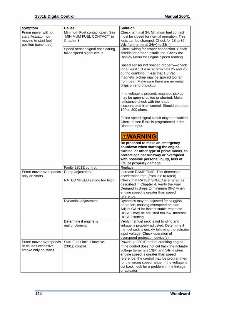
2301E Digital Control Manual 26641
124 Woodward
Symptom Cause SolutionPrime mover will not start. Actuator not moving to start fuel position (continued).
Minimum Fuel contact open. See “MINIMUM FUEL CONTACT” in Chapter 3.
Check terminal 34. Minimum fuel contact must be closed for normal operation. This logic can be changed. Check for 18 to 36 Vdc from terminal 34(+) to 33(–).
Speed sensor signal not clearing failed speed signal circuit.
Check wiring for proper connection. Check shields for proper installation. Check the Display Menu for Engine Speed reading. Speed sensor not spaced properly—check for at least 1.0 V ac at terminals 25 and 26 during cranking. If less that 1.0 Vac, magnetic pickup may be spaced too far from gear. Make sure there are no metal chips on end of pickup. If no voltage is present, magnetic pickup may be open-circuited or shorted. Make resistance check with the leads disconnected from control. Should be about 100 to 300 ohms. Failed speed signal circuit may be disabled. Check to see if this is programmed in the Discrete Input.
Be prepared to make an emergency shutdown when starting the engine, turbine, or other type of prime mover, to protect against runaway or overspeed with possible personal injury, loss of life, or property damage.
Faulty 2301E control. Replace. Prime mover overspeeds only on starts.
Ramp adjustment. Increase RAMP TIME. This decreases acceleration rate (from idle to rated).
RATED SPEED setting too high. Check that RATED SPEED is entered as described in Chapter 4. Verify the Fuel Demand % drops to minimum (0%) when engine speed is greater than speed reference.
Dynamics adjustment. Dynamics may be adjusted for sluggish operation, causing overspeed on start. Adjust GAIN for fastest stable response. RESET may be adjusted too low. Increase RESET setting.
Determine if engine is malfunctioning.
Verify that fuel rack is not binding and linkage is properly adjusted. Determine if the fuel rack is quickly following the actuator input voltage. Check operation of overspeed protection device(s).
Prime mover overspeeds or causes excessive smoke only on starts.
Start Fuel Limit is inactive. Power up 2301E before cranking engine. 2301E control. If the control does not cut back the actuator
voltage [terminals 13(+) and 14(-)] when engine speed is greater than speed reference, the control may be programmed for the wrong speed range. If the voltage is cut back, look for a problem in the linkage or actuator.
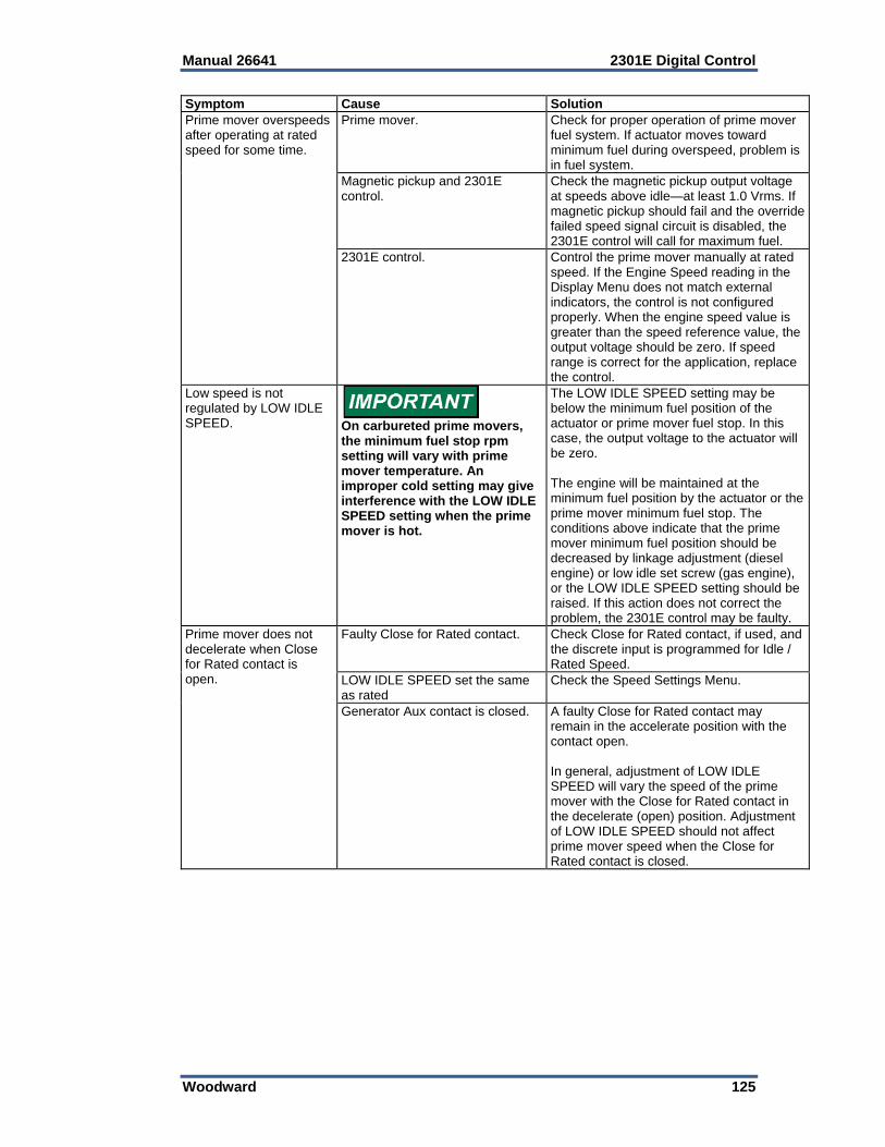
Manual 26641 2301E Digital Control
Woodward 125
Symptom Cause SolutionPrime mover overspeeds after operating at rated speed for some time.
Prime mover. Check for proper operation of prime mover fuel system. If actuator moves toward minimum fuel during overspeed, problem is in fuel system.
Magnetic pickup and 2301E control.
Check the magnetic pickup output voltage at speeds above idle—at least 1.0 Vrms. If magnetic pickup should fail and the override failed speed signal circuit is disabled, the 2301E control will call for maximum fuel.
2301E control. Control the prime mover manually at rated speed. If the Engine Speed reading in the Display Menu does not match external indicators, the control is not configured properly. When the engine speed value is greater than the speed reference value, the output voltage should be zero. If speed range is correct for the application, replace the control.
Low speed is not regulated by LOW IDLE SPEED.
On carbureted prime movers, the minimum fuel stop rpm setting will vary with prime mover temperature. An improper cold setting may give interference with the LOW IDLE SPEED setting when the prime mover is hot.
The LOW IDLE SPEED setting may be below the minimum fuel position of the actuator or prime mover fuel stop. In this case, the output voltage to the actuator will be zero. The engine will be maintained at the minimum fuel position by the actuator or the prime mover minimum fuel stop. The conditions above indicate that the prime mover minimum fuel position should be decreased by linkage adjustment (diesel engine) or low idle set screw (gas engine), or the LOW IDLE SPEED setting should be raised. If this action does not correct the problem, the 2301E control may be faulty.
Prime mover does not decelerate when Close for Rated contact is open.
Faulty Close for Rated contact. Check Close for Rated contact, if used, and the discrete input is programmed for Idle / Rated Speed.
LOW IDLE SPEED set the same as rated
Check the Speed Settings Menu.
Generator Aux contact is closed. A faulty Close for Rated contact may remain in the accelerate position with the contact open. In general, adjustment of LOW IDLE SPEED will vary the speed of the prime mover with the Close for Rated contact in the decelerate (open) position. Adjustment of LOW IDLE SPEED should not affect prime mover speed when the Close for Rated contact is closed.
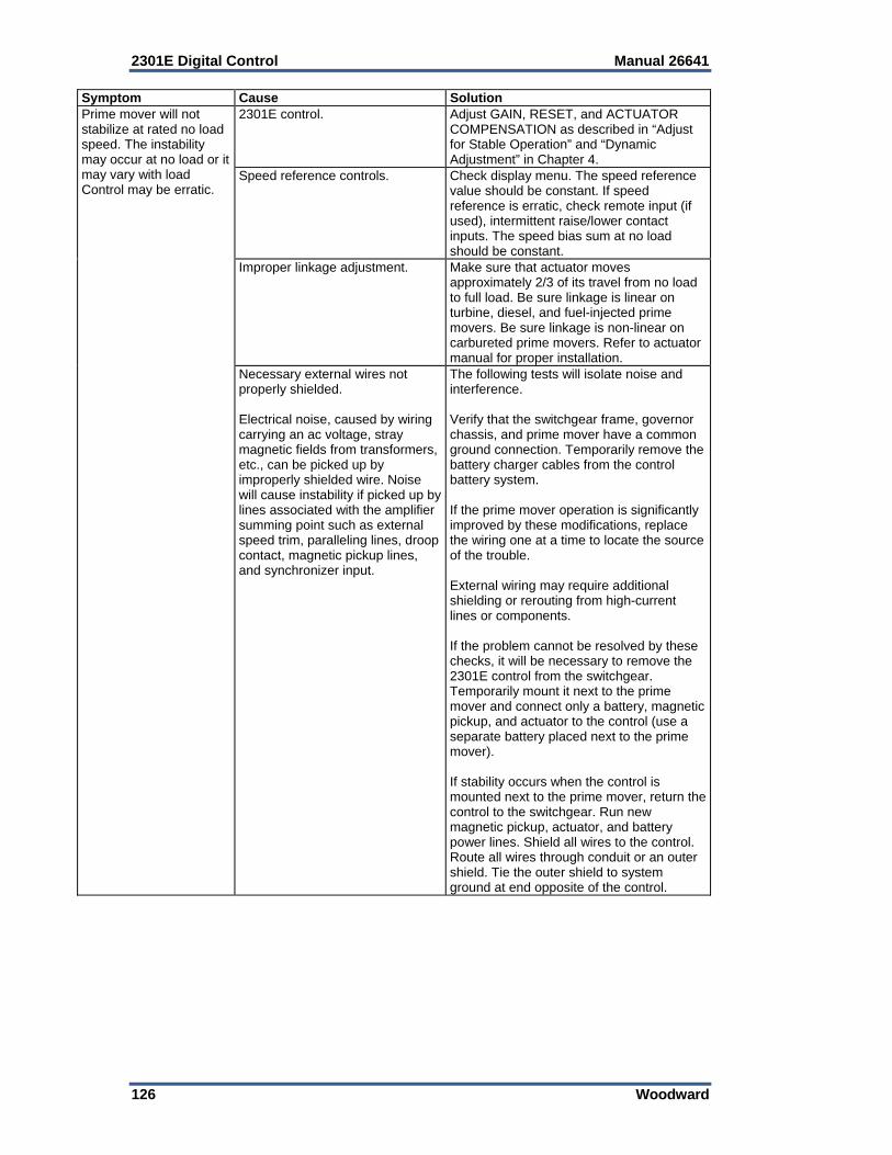
2301E Digital Control Manual 26641
126 Woodward
Symptom Cause SolutionPrime mover will not stabilize at rated no load speed. The instability may occur at no load or it may vary with load Control may be erratic.
2301E control. Adjust GAIN, RESET, and ACTUATOR COMPENSATION as described in “Adjust for Stable Operation” and “Dynamic Adjustment” in Chapter 4.
Speed reference controls. Check display menu. The speed reference value should be constant. If speed reference is erratic, check remote input (if used), intermittent raise/lower contact inputs. The speed bias sum at no load should be constant.
Improper linkage adjustment. Make sure that actuator moves approximately 2/3 of its travel from no load to full load. Be sure linkage is linear on turbine, diesel, and fuel-injected prime movers. Be sure linkage is non-linear on carbureted prime movers. Refer to actuator manual for proper installation.
Necessary external wires not properly shielded. Electrical noise, caused by wiring carrying an ac voltage, stray magnetic fields from transformers, etc., can be picked up by improperly shielded wire. Noise will cause instability if picked up by lines associated with the amplifier summing point such as external speed trim, paralleling lines, droop contact, magnetic pickup lines, and synchronizer input.
The following tests will isolate noise and interference. Verify that the switchgear frame, governor chassis, and prime mover have a common ground connection. Temporarily remove the battery charger cables from the control battery system. If the prime mover operation is significantly improved by these modifications, replace the wiring one at a time to locate the source of the trouble. External wiring may require additional shielding or rerouting from high-current lines or components. If the problem cannot be resolved by these checks, it will be necessary to remove the 2301E control from the switchgear. Temporarily mount it next to the prime mover and connect only a battery, magnetic pickup, and actuator to the control (use a separate battery placed next to the prime mover). If stability occurs when the control is mounted next to the prime mover, return the control to the switchgear. Run new magnetic pickup, actuator, and battery power lines. Shield all wires to the control. Route all wires through conduit or an outer shield. Tie the outer shield to system ground at end opposite of the control.
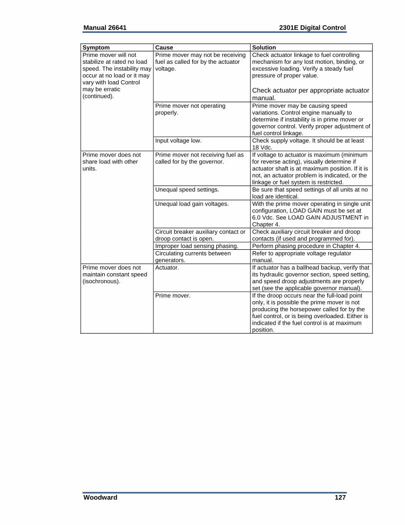
Manual 26641 2301E Digital Control
Woodward 127
Symptom Cause SolutionPrime mover will not stabilize at rated no load speed. The instability may occur at no load or it may vary with load Control may be erratic (continued).
Prime mover may not be receiving fuel as called for by the actuator voltage.
Check actuator linkage to fuel controlling mechanism for any lost motion, binding, or excessive loading. Verify a steady fuel pressure of proper value. Check actuator per appropriate actuator manual.
Prime mover not operating properly.
Prime mover may be causing speed variations. Control engine manually to determine if instability is in prime mover or governor control. Verify proper adjustment of fuel control linkage.
Input voltage low. Check supply voltage. It should be at least 18 Vdc.
Prime mover does not share load with other units.
Prime mover not receiving fuel as called for by the governor.
If voltage to actuator is maximum (minimum for reverse acting), visually determine if actuator shaft is at maximum position. If it is not, an actuator problem is indicated, or the linkage or fuel system is restricted.
Unequal speed settings. Be sure that speed settings of all units at no load are identical.
Unequal load gain voltages. With the prime mover operating in single unit configuration, LOAD GAIN must be set at 6.0 Vdc. See LOAD GAIN ADJUSTMENT in Chapter 4.
Circuit breaker auxiliary contact or droop contact is open.
Check auxiliary circuit breaker and droop contacts (if used and programmed for).
Improper load sensing phasing. Perform phasing procedure in Chapter 4.Circulating currents between generators.
Refer to appropriate voltage regulator manual.
Prime mover does not maintain constant speed (isochronous).
Actuator. If actuator has a ballhead backup, verify that its hydraulic governor section, speed setting, and speed droop adjustments are properly set (see the applicable governor manual).
Prime mover. If the droop occurs near the full-load point only, it is possible the prime mover is not producing the horsepower called for by the fuel control, or is being overloaded. Either is indicated if the fuel control is at maximum position.
2301E Digital Control Manual 26641
128 Woodward
Chapter 8. Communications
Modbus Communication The 2301E control can communicate with plant distributed control systems or CRT-based operator control panels through the RS-422 communication port. The communication port supports RS-422 communications using RTU Modbus transmission protocols. Modbus communications is set for default on the RS-422 serial port and the settings used in Service Menu Z**COMM PORTS**. Modbus utilizes a master/slave protocol which determines how a communication network’s master and slave devices establish and break contact, how a sender is identified, how messages are exchanged, and how errors are detected.
Monitor Only The Modbus communication port is programmed to update all information to all registers. This allows the 2301E to be monitored, but not controlled from an external device. By simply connecting a monitoring device, configured to communicate through Modbus, and to the 2301E’s defaulted protocol settings (parity, stop bits, etc.), this device can be used to monitor all the 2301E’s controlling parameters, modes, etc., without affecting control. To use the 2301E port, it must be configured properly.
Monitor and Control To control the inputs by Modbus, parameter “01 ENABLE MODBUS CONTROL in Service Menu Z**COMM Port** should be set TRUE. Once a Modbus port is activated by the Modbus selector command, the 2301E will accept an external network master device. This allows a Modbus-compatible device to monitor and perform all 2301E mode parameters and commands. To use a 2301E port it must be configured properly. Modbus Control, when activated, is in parallel with the Discrete Inputs through an “OR” input. This means that the Discrete Inputs or the Modbus inputs have control over each the functions.
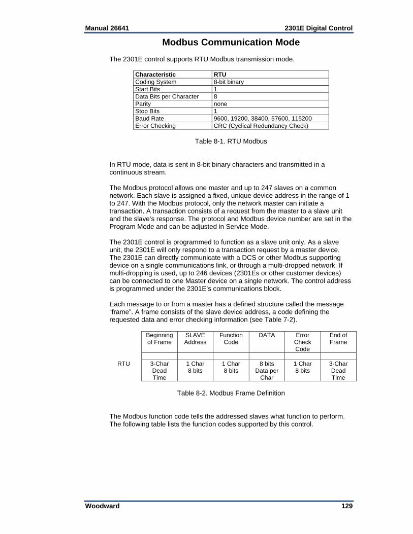
Manual 26641 2301E Digital Control
Woodward 129
Modbus Communication Mode The 2301E control supports RTU Modbus transmission mode.
Characteristic RTUCoding System 8-bit binary Start Bits 1 Data Bits per Character 8 Parity none Stop Bits 1 Baud Rate 9600, 19200, 38400, 57600, 115200 Error Checking CRC (Cyclical Redundancy Check)
Table 8-1. RTU Modbus
In RTU mode, data is sent in 8-bit binary characters and transmitted in a continuous stream. The Modbus protocol allows one master and up to 247 slaves on a common network. Each slave is assigned a fixed, unique device address in the range of 1 to 247. With the Modbus protocol, only the network master can initiate a transaction. A transaction consists of a request from the master to a slave unit and the slave’s response. The protocol and Modbus device number are set in the Program Mode and can be adjusted in Service Mode. The 2301E control is programmed to function as a slave unit only. As a slave unit, the 2301E will only respond to a transaction request by a master device. The 2301E can directly communicate with a DCS or other Modbus supporting device on a single communications link, or through a multi-dropped network. If multi-dropping is used, up to 246 devices (2301Es or other customer devices) can be connected to one Master device on a single network. The control address is programmed under the 2301E’s communications block. Each message to or from a master has a defined structure called the message “frame”. A frame consists of the slave device address, a code defining the requested data and error checking information (see Table 7-2).
Beginning of Frame
SLAVE Address
Function Code
DATA Error Check Code
End of Frame
RTU 3-Char
Dead Time
1 Char 8 bits
1 Char 8 bits
8 bits Data per
Char
1 Char 8 bits
3-Char Dead Time
Table 8-2. Modbus Frame Definition
The Modbus function code tells the addressed slaves what function to perform. The following table lists the function codes supported by this control.
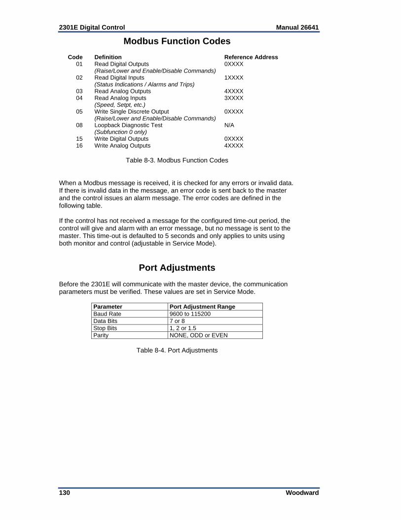
2301E Digital Control Manual 26641
130 Woodward
Modbus Function Codes Code Definition Reference Address 01 Read Digital Outputs 0XXXX (Raise/Lower and Enable/Disable Commands) 02 Read Digital Inputs 1XXXX (Status Indications / Alarms and Trips) 03 Read Analog Outputs 4XXXX 04 Read Analog Inputs 3XXXX (Speed, Setpt, etc.) 05 Write Single Discrete Output 0XXXX (Raise/Lower and Enable/Disable Commands) 08 Loopback Diagnostic Test N/A (Subfunction 0 only) 15 Write Digital Outputs 0XXXX 16 Write Analog Outputs 4XXXX
Table 8-3. Modbus Function Codes When a Modbus message is received, it is checked for any errors or invalid data. If there is invalid data in the message, an error code is sent back to the master and the control issues an alarm message. The error codes are defined in the following table. If the control has not received a message for the configured time-out period, the control will give and alarm with an error message, but no message is sent to the master. This time-out is defaulted to 5 seconds and only applies to units using both monitor and control (adjustable in Service Mode).
Port Adjustments Before the 2301E will communicate with the master device, the communication parameters must be verified. These values are set in Service Mode.
Parameter Port Adjustment Range Baud Rate 9600 to 115200 Data Bits 7 or 8 Stop Bits 1, 2 or 1.5 Parity NONE, ODD or EVEN
Table 8-4. Port Adjustments
Manual 26641 2301E Digital Control
Woodward 131
2301E Control Modbus Addresses The Modbus communication ports in the 2301E are programmed for unique Modbus addresses. A complete listing of these addresses for your application is located at the end of this section in the manual. The Modbus address listing consists of Boolean Writes, Boolean Reads, Analog Reads and Analog Writes. The Boolean reads and writes are also referred to as input and holding coils. The analog reads and writes are also referred to as input registers and holding registers. All values that can be addressed by Modbus are considered to be discrete and numeric. The discrete values are a 1 bit binary, on or off value and the numerics are 16 bit values. Discrete values are sometimes referred to as coils or digitals and numerics are referred to as registers or analogs. All read/write registers are interpreted by the 2301E as signed 16 bit integer values. Since Modbus can only handle integers, values that require a decimal point in the Modbus Master Device are multiplied by a scaling constant before being sent by the 2301E. See Appendix B for the default communication constants and ranges. Boolean Writes Boolean Writes are logic signals that are writable to the 2301E control. An example of a Boolean write value would be raise or lower commands. A logical true denoted by the value 1 will cause the command listed in the description to be executed. If a RUN (address 0.0002) command is given it will be latched. To reset the latch remove the RUN contact and give a command to STOP (address 0.0003). This is applicable for the following commands: 0.0002 Run (latch) 0.0003 Stop (reset latch) 0.0004 Failed Speed Override ON (latched) 0.0005 Failed Speed Override OFF (reset latch) 0.0006 Rated (latched) 0.0007 Idle (reset latch) 0.0010 Isoch (latched) 0.0011 Droop (reset latch) 0.0012 Baseload ON (latched) 0.0013 Baseload OFF (reset latch) Boolean Reads Boolean Reads are logic signals that are readable from, but not writable to, the 2301E. An example of a Boolean read value would be a turbine trip status indication. The logic true will have the value 1 if the statement in the description column is true and a 0 if false. The ‘1:’ term in the address identifies a logic true. The 2301E supports Modbus function code 2, which involves reading selected logic signals.

2301E Digital Control Manual 26641
132 Woodward
Analog Reads Input registers are analog values that are readable from, but not writable to, the 2301E. Turbine speed is an example of an analog read value. The values of the input registers are stored internally to the control as floating point numbers representing engineering units (kPa or rpm). The values transmitted are integers ranging from –32767 to +32767. Since Modbus can only handle integers, values that have a decimal point are multiplied by a constant before being sent by Modbus. For example, these input registers may be listed as the Modbus value `x100’ or `x10’ under the description heading to denote the value is multiplied by a scaling constant. This will allow transmission of decimal parts of a unit if this is necessary for better resolution. See the 2301E Service Mode for default communication constants and ranges. The 2301E supports Modbus function code 4, which involves reading selected input registers. Analog Writes Holding registers are analog values that are writable to the 2301E. These values can also be read by a device performing an error check. An example of an analog write value would be a direct speed setpoint as opposed to raise and lower commands. The values of the holding registers are also stored in the control as numbers representing engineering units (kPa or rpm). The 2301E supports Modbus function codes 3, 6, and 16. These correspond to reading selected holding registers, writing to a single holding register and writing to multiple holding registers respectively. Appendix B lists the addresses and descriptions of all Boolean and analog reads and writes.
Modbus Scale Factors Modbus has two limitations: only integers can be sent across the value is limited between –32767 and +32767. These limitations can be overcome by scaling the value before it is sent across the Modbus. The default scale factor for analog values is 1. The scale factor can be changed in the Watch Window (INTFC.COM) between 1 and 1000. These scaled parameters and their scale factor are available through the Modbus. Values that require a decimal point must be multiplied by the scale factor (10, 100 or 1000) before being sent across the Modbus. The value sent is then divided by the scale factor in the Master. The Scale Factor adjusts all associated analog reads accordingly. The Multiplier (scale factor) can be changed in the Watch Window.
Shutdown Command through Modbus Two different types of shutdown commands (emergency and controlled) can be issued through Modbus. The Emergency Shutdown command instantly takes the actuator current to zero and activates the shutdown relay. The Controlled Shutdown function is used to stop the engine in a controlled manner, as opposed to an Emergency Trip. When a STOP command (controlled shutdown) is issued the shutdown relay is not activated. The Emergency Shutdown and Controlled Shutdown commands do not influence the operation of the Trip Relay.

Manual 26641 2301E Digital Control
Woodward 133
Start Command through Modbus The start-up permissive of a prime mover is possible from a command through the Modbus. The open/close of contact inputs (RUN/SHUTDOWN, etc.) serve as the independent command in Modbus BW. These commands operate as a momentary input. Which means the input from the Modbus commands are latching.
For More Modbus Information Detailed information on the Modbus protocol is presented in “Reference Guide PI-MBUS-300” published by AEC Corp./Modicon Inc., formerly Gould Inc. To implement your own source code, you must register with Modicon. Registration includes purchasing document PI-MBUS-303 and signing a non-disclosure agreement. You can register to use Modbus at your nearest Modicon field office. To find the office nearest you, contact Modicon Technical Support at +1-800-468-5342 (in North America).

2301E Digital Control Manual 26641
134 Woodward
Chapter 9. Product Support and Service Options
Product Support Options If you are experiencing problems with the installation, or unsatisfactory performance of a Woodward product, the following options are available: 1. Consult the troubleshooting guide in the manual. 2. Contact the OE Manufacturer or Packager of your system. 3. Contact the Woodward Business Partner serving your area. 4. Contact Woodward technical assistance via email
([email protected]) with detailed information on the product, application, and symptoms. Your email will be forwarded to an appropriate expert on the product and application to respond by telephone or return email.
5. If the issue cannot be resolved, you can select a further course of action to pursue based on the available services listed in this chapter.
OEM or Packager Support: Many Woodward controls and control devices are installed into the equipment system and programmed by an Original Equipment Manufacturer (OEM) or Equipment Packager at their factory. In some cases, the programming is password-protected by the OEM or packager, and they are the best source for product service and support. Warranty service for Woodward products shipped with an equipment system should also be handled through the OEM or Packager. Please review your equipment system documentation for details. Woodward Business Partner Support: Woodward works with and supports a global network of independent business partners whose mission is to serve the users of Woodward controls, as described here:
A Full-Service Distributor has the primary responsibility for sales, service, system integration solutions, technical desk support, and aftermarket marketing of standard Woodward products within a specific geographic area and market segment.
An Authorized Independent Service Facility (AISF) provides authorized service that includes repairs, repair parts, and warranty service on Woodward's behalf. Service (not new unit sales) is an AISF's primary mission.
A Recognized Engine Retrofitter (RER) is an independent company that does retrofits and upgrades on reciprocating gas engines and dual-fuel conversions, and can provide the full line of Woodward systems and components for the retrofits and overhauls, emission compliance upgrades, long term service contracts, emergency repairs, etc.
A current list of Woodward Business Partners is available at www.woodward.com/directory.
Product Service Options Depending on the type of product, the following options for servicing Woodward products may be available through your local Full-Service Distributor or the OEM or Packager of the equipment system. Replacement/Exchange (24-hour service) Flat Rate Repair Flat Rate Remanufacture
Manual 26641 2301E Digital Control
Woodward 135
Replacement/Exchange: Replacement/Exchange is a premium program designed for the user who is in need of immediate service. It allows you to request and receive a like-new replacement unit in minimum time (usually within 24 hours of the request), providing a suitable unit is available at the time of the request, thereby minimizing costly downtime. This option allows you to call your Full-Service Distributor in the event of an unexpected outage, or in advance of a scheduled outage, to request a replacement control unit. If the unit is available at the time of the call, it can usually be shipped out within 24 hours. You replace your field control unit with the like-new replacement and return the field unit to the Full-Service Distributor. Flat Rate Repair: Flat Rate Repair is available for many of the standard mechanical products and some of the electronic products in the field. This program offers you repair service for your products with the advantage of knowing in advance what the cost will be. Flat Rate Remanufacture: Flat Rate Remanufacture is very similar to the Flat Rate Repair option, with the exception that the unit will be returned to you in “like-new” condition. This option is applicable to mechanical products only.
Returning Equipment for Repair If a control (or any part of an electronic control) is to be returned for repair, please contact your Full-Service Distributor in advance to obtain Return Authorization and shipping instructions. When shipping the item(s), attach a tag with the following information: return number; name and location where the control is installed; name and phone number of contact person; complete Woodward part number(s) and serial number(s); description of the problem; instructions describing the desired type of repair.
Packing a Control Use the following materials when returning a complete control: protective caps on any connectors; antistatic protective bags on all electronic modules; packing materials that will not damage the surface of the unit; at least 100 mm (4 inches) of tightly packed, industry-approved packing
material; a packing carton with double walls; a strong tape around the outside of the carton for increased strength.
To prevent damage to electronic components caused by improper handling, read and observe the precautions in Woodward manual 82715, Guide for Handling and Protection of Electronic Controls, Printed Circuit Boards, and Modules.
Replacement Parts When ordering replacement parts for controls, include the following information: the part number(s) (XXXX-XXXX) that is on the enclosure nameplate; the unit serial number, which is also on the nameplate.

2301E Digital Control Manual 26641
136 Woodward
Engineering Services Woodward’s Full-Service Distributors offer various Engineering Services for our products. For these services, you can contact the Distributor by telephone or by email. Technical Support Product Training Field Service Technical Support is available from your equipment system supplier, your local Full-Service Distributor, or from many of Woodward’s worldwide locations, depending upon the product and application. This service can assist you with technical questions or problem solving during the normal business hours of the Woodward location you contact. Product Training is available as standard classes at many Distributor locations. Customized classes are also available, which can be tailored to your needs and held at one of our Distributor locations or at your site. This training, conducted by experienced personnel, will assure that you will be able to maintain system reliability and availability. Field Service engineering on-site support is available, depending on the product and location, from one of our Full-Service Distributors. The field engineers are experienced both on Woodward products as well as on much of the non-Woodward equipment with which our products interface. For information on these services, please contact one of the Full-Service Distributors listed at www.woodward.com/directory.
Contacting Woodward’s Support Organization For the name of your nearest Woodward Full-Service Distributor or service facility, please consult our worldwide directory published at www.woodward.com/directory. You can also contact the Woodward Customer Service Department at one of the following Woodward facilities to obtain the address and phone number of the nearest facility at which you can obtain information and service.
Products Used In Electrical Power Systems
Facility ---------------- Phone Number Brazil ------------- +55 (19) 3708 4800 China ----------- +86 (512) 6762 6727 Germany: Kempen ---- +49 (0) 21 52 14 51 Stuttgart -- +49 (711) 78954-510 India --------------- +91 (129) 4097100 Japan -------------- +81 (43) 213-2191 Korea -------------- +82 (51) 636-7080 Poland --------------- +48 12 295 13 00 United States ---- +1 (970) 482-5811
Products Used In Engine Systems
Facility ---------------- Phone Number Brazil ------------- +55 (19) 3708 4800 China ----------- +86 (512) 6762 6727 Germany ------- +49 (711) 78954-510 India --------------- +91 (129) 4097100 Japan -------------- +81 (43) 213-2191 Korea -------------- +82 (51) 636-7080 The Netherlands - +31 (23) 5661111 United States ---- +1 (970) 482-5811
Products Used In Industrial Turbomachinery
Systems Facility ---------------- Phone Number Brazil ------------- +55 (19) 3708 4800 China ----------- +86 (512) 6762 6727 India --------------- +91 (129) 4097100 Japan -------------- +81 (43) 213-2191 Korea -------------- +82 (51) 636-7080 The Netherlands - +31 (23) 5661111 Poland --------------- +48 12 295 13 00 United States ---- +1 (970) 482-5811
For the most current product support and contact information, please visit our website directory at www.woodward.com/directory.

Manual 26641 2301E Digital Control
Woodward 137
Technical Assistance
If you need to contact technical assistance, you will need to provide the following information. Please write it down here before contacting the Engine OEM, the Packager, a Woodward Business Partner, or the Woodward factory:
General
Your Name
Site Location
Phone Number
Fax Number
Prime Mover Information
Manufacturer
Engine Model Number
Number of Cylinders
Type of Fuel (gas, gaseous, diesel, dual-fuel, etc.)
Power Output Rating
Application (power generation, marine, etc.)
Control/Governor Information
Control/Governor #1
Woodward Part Number & Rev. Letter
Control Description or Governor Type
Serial Number
Control/Governor #2
Woodward Part Number & Rev. Letter
Control Description or Governor Type
Serial Number
Control/Governor #3
Woodward Part Number & Rev. Letter
Control Description or Governor Type
Serial Number
Symptoms
Description
If you have an electronic or programmable control, please have the adjustment setting positions or the menu settings written down and with you at the time of the call.
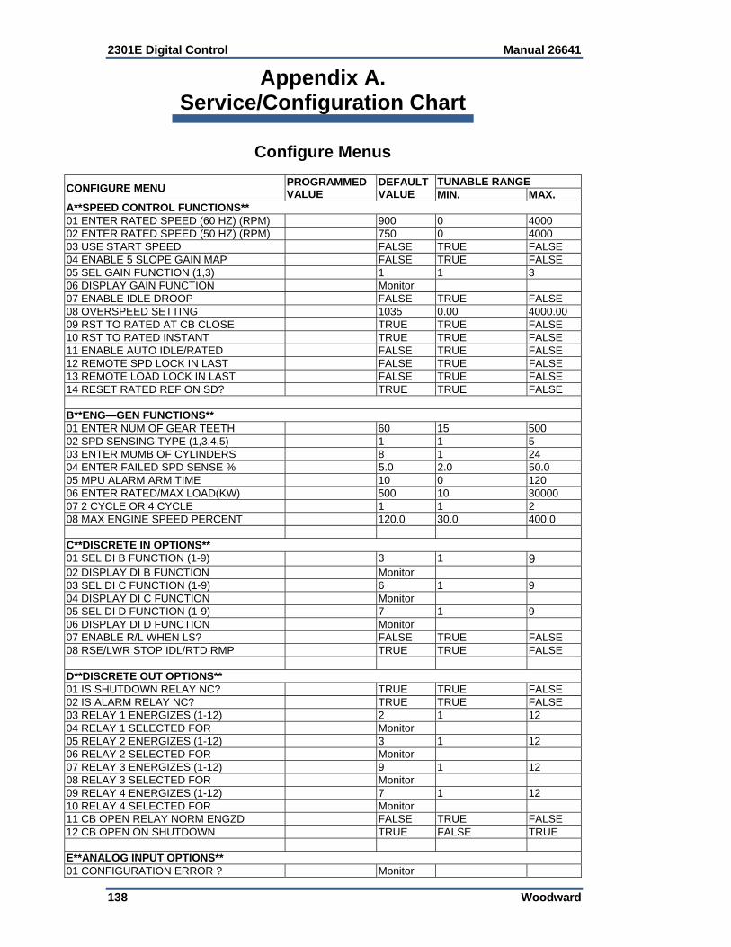
2301E Digital Control Manual 26641
138 Woodward
Appendix A. Service/Configuration Chart
Configure Menus
CONFIGURE MENU PROGRAMMED VALUE
DEFAULT VALUE
TUNABLE RANGE MIN. MAX.
A**SPEED CONTROL FUNCTIONS** 01 ENTER RATED SPEED (60 HZ) (RPM) 900 0 4000 02 ENTER RATED SPEED (50 HZ) (RPM) 750 0 4000 03 USE START SPEED FALSE TRUE FALSE 04 ENABLE 5 SLOPE GAIN MAP FALSE TRUE FALSE 05 SEL GAIN FUNCTION (1,3) 1 1 3 06 DISPLAY GAIN FUNCTION Monitor 07 ENABLE IDLE DROOP FALSE TRUE FALSE 08 OVERSPEED SETTING 1035 0.00 4000.00 09 RST TO RATED AT CB CLOSE TRUE TRUE FALSE 10 RST TO RATED INSTANT TRUE TRUE FALSE 11 ENABLE AUTO IDLE/RATED FALSE TRUE FALSE 12 REMOTE SPD LOCK IN LAST FALSE TRUE FALSE 13 REMOTE LOAD LOCK IN LAST FALSE TRUE FALSE 14 RESET RATED REF ON SD? TRUE TRUE FALSE B**ENG—GEN FUNCTIONS** 01 ENTER NUM OF GEAR TEETH 60 15 500 02 SPD SENSING TYPE (1,3,4,5) 1 1 5 03 ENTER MUMB OF CYLINDERS 8 1 24 04 ENTER FAILED SPD SENSE % 5.0 2.0 50.0 05 MPU ALARM ARM TIME 10 0 120 06 ENTER RATED/MAX LOAD(KW) 500 10 30000 07 2 CYCLE OR 4 CYCLE 1 1 2 08 MAX ENGINE SPEED PERCENT 120.0 30.0 400.0 C**DISCRETE IN OPTIONS** 01 SEL DI B FUNCTION (1-9) 3 1 9 02 DISPLAY DI B FUNCTION Monitor 03 SEL DI C FUNCTION (1-9) 6 1 9 04 DISPLAY DI C FUNCTION Monitor 05 SEL DI D FUNCTION (1-9) 7 1 9 06 DISPLAY DI D FUNCTION Monitor 07 ENABLE R/L WHEN LS? FALSE TRUE FALSE 08 RSE/LWR STOP IDL/RTD RMP TRUE TRUE FALSE D**DISCRETE OUT OPTIONS** 01 IS SHUTDOWN RELAY NC? TRUE TRUE FALSE 02 IS ALARM RELAY NC? TRUE TRUE FALSE 03 RELAY 1 ENERGIZES (1-12) 2 1 12 04 RELAY 1 SELECTED FOR Monitor 05 RELAY 2 ENERGIZES (1-12) 3 1 12 06 RELAY 2 SELECTED FOR Monitor 07 RELAY 3 ENERGIZES (1-12) 9 1 12 08 RELAY 3 SELECTED FOR Monitor 09 RELAY 4 ENERGIZES (1-12) 7 1 12 10 RELAY 4 SELECTED FOR Monitor 11 CB OPEN RELAY NORM ENGZD FALSE TRUE FALSE 12 CB OPEN ON SHUTDOWN TRUE FALSE TRUE E**ANALOG INPUT OPTIONS** 01 CONFIGURATION ERROR ? Monitor
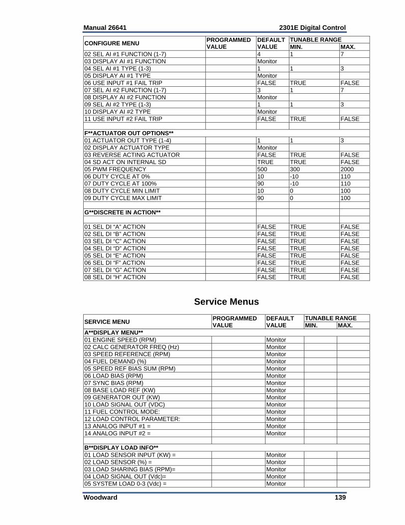
Manual 26641 2301E Digital Control
Woodward 139
CONFIGURE MENU PROGRAMMED VALUE
DEFAULT VALUE
TUNABLE RANGEMIN. MAX.
02 SEL AI #1 FUNCTION (1-7) 4 1 703 DISPLAY AI #1 FUNCTION Monitor 04 SEL AI #1 TYPE (1-3) 1 1 305 DISPLAY AI #1 TYPE Monitor 06 USE INPUT #1 FAIL TRIP FALSE TRUE FALSE07 SEL AI #2 FUNCTION (1-7) 3 1 708 DISPLAY AI #2 FUNCTION Monitor 09 SEL AI #2 TYPE (1-3) 1 1 310 DISPLAY AI #2 TYPE Monitor 11 USE INPUT #2 FAIL TRIP FALSE TRUE FALSE F**ACTUATOR OUT OPTIONS**01 ACTUATOR OUT TYPE (1-4) 1 1 302 DISPLAY ACTUATOR TYPE Monitor 03 REVERSE ACTING ACTUATOR FALSE TRUE FALSE04 SD ACT ON INTERNAL SD TRUE TRUE FALSE 05 PWM FREQUENCY 500 300 2000 06 DUTY CYCLE AT 0% 10 -10 110 07 DUTY CYCLE AT 100% 90 -10 110 08 DUTY CYCLE MIN LIMIT 10 0 100 09 DUTY CYCLE MAX LIMIT 90 0 100 G**DISCRETE IN ACTION** 01 SEL DI “A” ACTION FALSE TRUE FALSE 02 SEL DI “B” ACTION FALSE TRUE FALSE 03 SEL DI “C” ACTION FALSE TRUE FALSE 04 SEL DI “D” ACTION FALSE TRUE FALSE 05 SEL DI “E” ACTION FALSE TRUE FALSE 06 SEL DI “F” ACTION FALSE TRUE FALSE 07 SEL DI “G” ACTION FALSE TRUE FALSE 08 SEL DI “H” ACTION FALSE TRUE FALSE
Service Menus
SERVICE MENU PROGRAMMED VALUE
DEFAULT VALUE
TUNABLE RANGEMIN. MAX.
A**DISPLAY MENU** 01 ENGINE SPEED (RPM) Monitor 02 CALC GENERATOR FREQ (Hz) Monitor 03 SPEED REFERENCE (RPM) Monitor 04 FUEL DEMAND (%) Monitor 05 SPEED REF BIAS SUM (RPM) Monitor 06 LOAD BIAS (RPM) Monitor 07 SYNC BIAS (RPM) Monitor 08 BASE LOAD REF (KW) Monitor 09 GENERATOR OUT (KW) Monitor 10 LOAD SIGNAL OUT (VDC) Monitor 11 FUEL CONTROL MODE: Monitor 12 LOAD CONTROL PARAMETER: Monitor 13 ANALOG INPUT #1 = Monitor 14 ANALOG INPUT #2 = Monitor B**DISPLAY LOAD INFO** 01 LOAD SENSOR INPUT (KW) = Monitor 02 LOAD SENSOR (%) = Monitor 03 LOAD SHARING BIAS (RPM)= Monitor 04 LOAD SIGNAL OUT (Vdc)= Monitor 05 SYSTEM LOAD 0-3 (Vdc) = Monitor
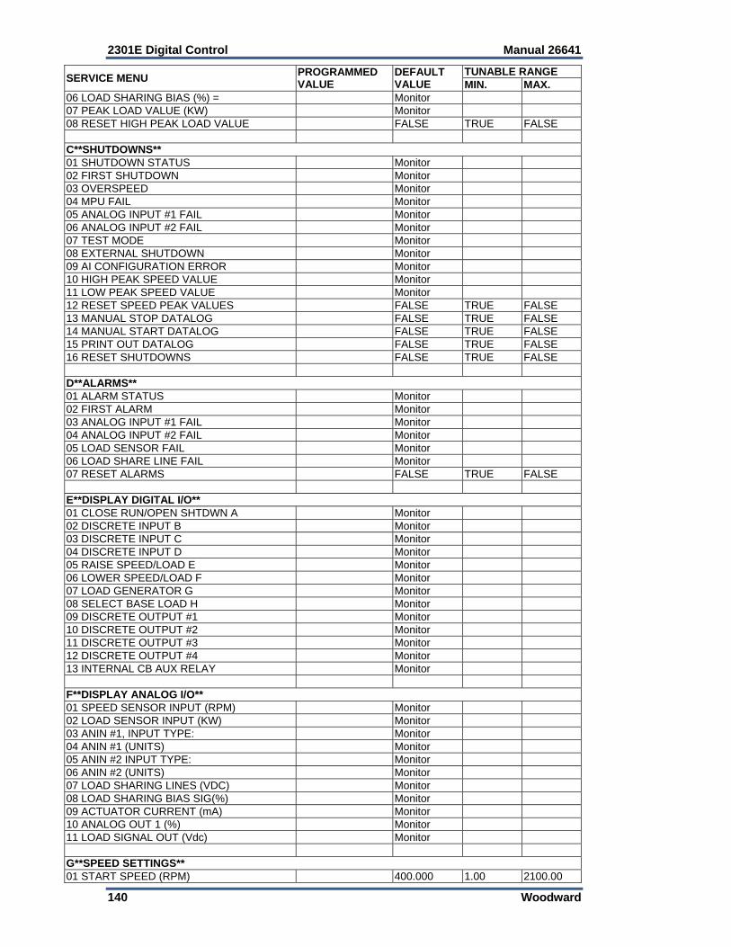
2301E Digital Control Manual 26641
140 Woodward
SERVICE MENU PROGRAMMED VALUE
DEFAULT VALUE
TUNABLE RANGE MIN. MAX.
06 LOAD SHARING BIAS (%) = Monitor 07 PEAK LOAD VALUE (KW) Monitor 08 RESET HIGH PEAK LOAD VALUE FALSE TRUE FALSE C**SHUTDOWNS** 01 SHUTDOWN STATUS Monitor 02 FIRST SHUTDOWN Monitor 03 OVERSPEED Monitor 04 MPU FAIL Monitor 05 ANALOG INPUT #1 FAIL Monitor 06 ANALOG INPUT #2 FAIL Monitor 07 TEST MODE Monitor 08 EXTERNAL SHUTDOWN Monitor 09 AI CONFIGURATION ERROR Monitor 10 HIGH PEAK SPEED VALUE Monitor 11 LOW PEAK SPEED VALUE Monitor 12 RESET SPEED PEAK VALUES FALSE TRUE FALSE 13 MANUAL STOP DATALOG FALSE TRUE FALSE 14 MANUAL START DATALOG FALSE TRUE FALSE 15 PRINT OUT DATALOG FALSE TRUE FALSE 16 RESET SHUTDOWNS FALSE TRUE FALSE D**ALARMS** 01 ALARM STATUS Monitor 02 FIRST ALARM Monitor 03 ANALOG INPUT #1 FAIL Monitor 04 ANALOG INPUT #2 FAIL Monitor 05 LOAD SENSOR FAIL Monitor 06 LOAD SHARE LINE FAIL Monitor 07 RESET ALARMS FALSE TRUE FALSE E**DISPLAY DIGITAL I/O** 01 CLOSE RUN/OPEN SHTDWN A Monitor 02 DISCRETE INPUT B Monitor 03 DISCRETE INPUT C Monitor 04 DISCRETE INPUT D Monitor 05 RAISE SPEED/LOAD E Monitor 06 LOWER SPEED/LOAD F Monitor 07 LOAD GENERATOR G Monitor 08 SELECT BASE LOAD H Monitor 09 DISCRETE OUTPUT #1 Monitor 10 DISCRETE OUTPUT #2 Monitor 11 DISCRETE OUTPUT #3 Monitor 12 DISCRETE OUTPUT #4 Monitor 13 INTERNAL CB AUX RELAY Monitor F**DISPLAY ANALOG I/O** 01 SPEED SENSOR INPUT (RPM) Monitor 02 LOAD SENSOR INPUT (KW) Monitor 03 ANIN #1, INPUT TYPE: Monitor 04 ANIN #1 (UNITS) Monitor 05 ANIN #2 INPUT TYPE: Monitor 06 ANIN #2 (UNITS) Monitor 07 LOAD SHARING LINES (VDC) Monitor 08 LOAD SHARING BIAS SIG(%) Monitor 09 ACTUATOR CURRENT (mA) Monitor 10 ANALOG OUT 1 (%) Monitor 11 LOAD SIGNAL OUT (Vdc) Monitor G**SPEED SETTINGS** 01 START SPEED (RPM) 400.000 1.00 2100.00
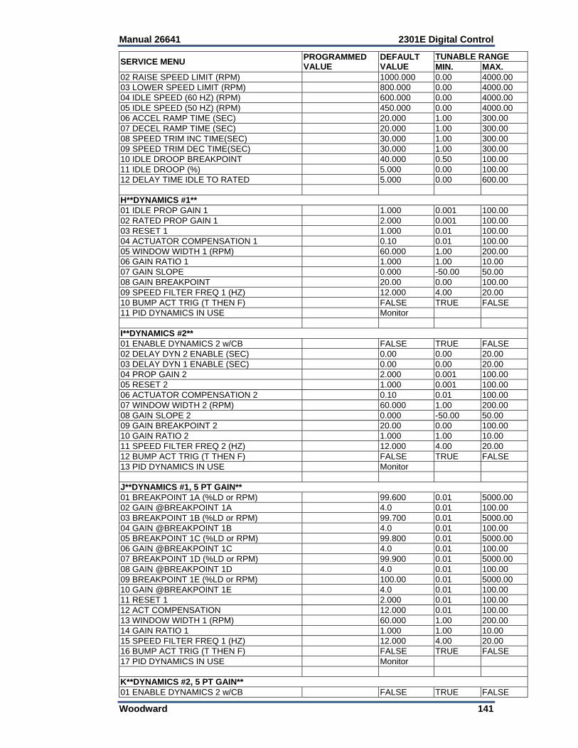
Manual 26641 2301E Digital Control
Woodward 141
SERVICE MENU PROGRAMMED VALUE
DEFAULT VALUE
TUNABLE RANGEMIN. MAX.
02 RAISE SPEED LIMIT (RPM) 1000.000 0.00 4000.0003 LOWER SPEED LIMIT (RPM) 800.000 0.00 4000.0004 IDLE SPEED (60 HZ) (RPM) 600.000 0.00 4000.0005 IDLE SPEED (50 HZ) (RPM) 450.000 0.00 4000.0006 ACCEL RAMP TIME (SEC) 20.000 1.00 300.0007 DECEL RAMP TIME (SEC) 20.000 1.00 300.0008 SPEED TRIM INC TIME(SEC) 30.000 1.00 300.0009 SPEED TRIM DEC TIME(SEC) 30.000 1.00 300.0010 IDLE DROOP BREAKPOINT 40.000 0.50 100.0011 IDLE DROOP (%) 5.000 0.00 100.0012 DELAY TIME IDLE TO RATED 5.000 0.00 600.00 H**DYNAMICS #1** 01 IDLE PROP GAIN 1 1.000 0.001 100.00 02 RATED PROP GAIN 1 2.000 0.001 100.0003 RESET 1 1.000 0.01 100.0004 ACTUATOR COMPENSATION 1 0.10 0.01 100.0005 WINDOW WIDTH 1 (RPM) 60.000 1.00 200.0006 GAIN RATIO 1 1.000 1.00 10.0007 GAIN SLOPE 0.000 -50.00 50.00 08 GAIN BREAKPOINT 20.00 0.00 100.00 09 SPEED FILTER FREQ 1 (HZ) 12.000 4.00 20.0010 BUMP ACT TRIG (T THEN F) FALSE TRUE FALSE11 PID DYNAMICS IN USE Monitor I**DYNAMICS #2** 01 ENABLE DYNAMICS 2 w/CB FALSE TRUE FALSE02 DELAY DYN 2 ENABLE (SEC) 0.00 0.00 20.0003 DELAY DYN 1 ENABLE (SEC) 0.00 0.00 20.0004 PROP GAIN 2 2.000 0.001 100.0005 RESET 2 1.000 0.001 100.0006 ACTUATOR COMPENSATION 2 0.10 0.01 100.0007 WINDOW WIDTH 2 (RPM) 60.000 1.00 200.0008 GAIN SLOPE 2 0.000 -50.00 50.00 09 GAIN BREAKPOINT 2 20.00 0.00 100.00 10 GAIN RATIO 2 1.000 1.00 10.0011 SPEED FILTER FREQ 2 (HZ) 12.000 4.00 20.0012 BUMP ACT TRIG (T THEN F) FALSE TRUE FALSE13 PID DYNAMICS IN USE Monitor J**DYNAMICS #1, 5 PT GAIN**01 BREAKPOINT 1A (%LD or RPM) 99.600 0.01 5000.0002 GAIN @BREAKPOINT 1A 4.0 0.01 100.0003 BREAKPOINT 1B (%LD or RPM) 99.700 0.01 5000.0004 GAIN @BREAKPOINT 1B 4.0 0.01 100.0005 BREAKPOINT 1C (%LD or RPM) 99.800 0.01 5000.0006 GAIN @BREAKPOINT 1C 4.0 0.01 100.0007 BREAKPOINT 1D (%LD or RPM) 99.900 0.01 5000.0008 GAIN @BREAKPOINT 1D 4.0 0.01 100.0009 BREAKPOINT 1E (%LD or RPM) 100.00 0.01 5000.0010 GAIN @BREAKPOINT 1E 4.0 0.01 100.0011 RESET 1 2.000 0.01 100.0012 ACT COMPENSATION 12.000 0.01 100.0013 WINDOW WIDTH 1 (RPM) 60.000 1.00 200.0014 GAIN RATIO 1 1.000 1.00 10.0015 SPEED FILTER FREQ 1 (HZ) 12.000 4.00 20.0016 BUMP ACT TRIG (T THEN F) FALSE TRUE FALSE17 PID DYNAMICS IN USE Monitor K**DYNAMICS #2, 5 PT GAIN**01 ENABLE DYNAMICS 2 w/CB FALSE TRUE FALSE
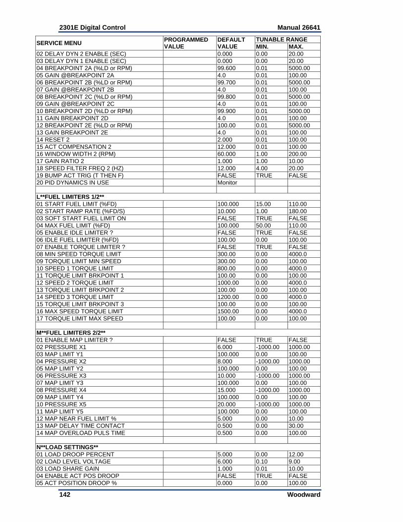
2301E Digital Control Manual 26641
142 Woodward
SERVICE MENU PROGRAMMED VALUE
DEFAULT VALUE
TUNABLE RANGE MIN. MAX.
02 DELAY DYN 2 ENABLE (SEC) 0.000 0.00 20.00 03 DELAY DYN 1 ENABLE (SEC) 0.000 0.00 20.00 04 BREAKPOINT 2A (%LD or RPM) 99.600 0.01 5000.00 05 GAIN @BREAKPOINT 2A 4.0 0.01 100.00 06 BREAKPOINT 2B (%LD or RPM) 99.700 0.01 5000.00 07 GAIN @BREAKPOINT 2B 4.0 0.01 100.00 08 BREAKPOINT 2C (%LD or RPM) 99.800 0.01 5000.00 09 GAIN @BREAKPOINT 2C 4.0 0.01 100.00 10 BREAKPOINT 2D (%LD or RPM) 99.900 0.01 5000.00 11 GAIN BREAKPOINT 2D 4.0 0.01 100.00 12 BREAKPOINT 2E (%LD or RPM) 100.00 0.01 5000.00 13 GAIN BREAKPOINT 2E 4.0 0.01 100.00 14 RESET 2 2.000 0.01 100.00 15 ACT COMPENSATION 2 12.000 0.01 100.00 16 WINDOW WIDTH 2 (RPM) 60.000 1.00 200.00 17 GAIN RATIO 2 1.000 1.00 10.00 18 SPEED FILTER FREQ 2 (HZ) 12.000 4.00 20.00 19 BUMP ACT TRIG (T THEN F) FALSE TRUE FALSE 20 PID DYNAMICS IN USE Monitor L**FUEL LIMITERS 1/2** 01 START FUEL LIMIT (%FD) 100.000 15.00 110.00 02 START RAMP RATE (%FD/S) 10.000 1.00 180.00 03 SOFT START FUEL LIMIT ON FALSE TRUE FALSE 04 MAX FUEL LIMIT (%FD) 100.000 50.00 110.00 05 ENABLE IDLE LIMITER ? FALSE TRUE FALSE 06 IDLE FUEL LIMITER (%FD) 100.00 0.00 100.00 07 ENABLE TORQUE LIMITER ? FALSE TRUE FALSE 08 MIN SPEED TORQUE LIMIT 300.00 0.00 4000.0 09 TORQUE LIMIT MIN SPEED 300.00 0.00 100.00 10 SPEED 1 TORQUE LIMIT 800.00 0.00 4000.0 11 TORQUE LIMIT BRKPOINT 1 100.00 0.00 100.00 12 SPEED 2 TORQUE LIMIT 1000.00 0.00 4000.0 13 TORQUE LIMIT BRKPOINT 2 100.00 0.00 100.00 14 SPEED 3 TORQUE LIMIT 1200.00 0.00 4000.0 15 TORQUE LIMIT BRKPOINT 3 100.00 0.00 100.00 16 MAX SPEED TORQUE LIMIT 1500.00 0.00 4000.0 17 TORQUE LIMIT MAX SPEED 100.00 0.00 100.00 M**FUEL LIMITERS 2/2** 01 ENABLE MAP LIMITER ? FALSE TRUE FALSE 02 PRESSURE X1 6.000 -1000.00 1000.00 03 MAP LIMIT Y1 100.000 0.00 100.00 04 PRESSURE X2 8.000 -1000.00 1000.00 05 MAP LIMIT Y2 100.000 0.00 100.00 06 PRESSURE X3 10.000 -1000.00 1000.00 07 MAP LIMIT Y3 100.000 0.00 100.00 08 PRESSURE X4 15.000 -1000.00 1000.00 09 MAP LIMIT Y4 100.000 0.00 100.00 10 PRESSURE X5 20.000 -1000.00 1000.00 11 MAP LIMIT Y5 100.000 0.00 100.00 12 MAP NEAR FUEL LIMIT % 5.000 0.00 10.00 13 MAP DELAY TIME CONTACT 0.500 0.00 30.00 14 MAP OVERLOAD PULS TIME 0.500 0.00 100.00 N**LOAD SETTINGS** 01 LOAD DROOP PERCENT 5.000 0.00 12.00 02 LOAD LEVEL VOLTAGE 6.000 0.10 9.00 03 LOAD SHARE GAIN 1.000 0.01 10.00 04 ENABLE ACT POS DROOP FALSE TRUE FALSE 05 ACT POSITION DROOP % 0.000 0.00 100.00

Manual 26641 2301E Digital Control
Woodward 143
SERVICE MENU PROGRAMMED VALUE
DEFAULT VALUE
TUNABLE RANGEMIN. MAX.
06 ACT OUT AT RATED NO LOAD 20.000 0.00 100.00 07 ACT OUT RATED FULL LOAD 80.000 0.00 100.00 08 BASE LOAD MINIMUM (KW) 20.000 10.00 30000.0009 BASE LOAD REFERENCE (KW) 50.000 0.00 30000.0010 BASE LOAD MAXIMUM (KW) 110.000 10.00 30000.0011 BASELOAD RAISE TIME(SEC) 60.000 1.00 600.0012 BASELOAD LOWER TIME(SEC) 60.000 1.00 600.0013 UNLOAD TRIP LEVEL (KW) 5.000 0.00 30000.0014 LOADING RATE (KW/SEC) 20.000 1.00 600.0015 UNLOADING RATE (KW/SEC) 20.000 1.00 600.0016 ENABLE FAST LOAD RATE FALSE TRUE FALSE17 FAST RAMP ENABLE LOAD(%) 80.000 1.00 110.0018 FAST RAMP RATE (KW/SEC) 60.000 1.00 600.00 O**ACTUATOR BUMP SETUP**01 ACT BUMP ENABLE FALSE TRUE FALSE02 ACT BUMP LEVEL (%FD) 1.000 0.00 25.0003 ACT BUMP DURATION (SEC) 0.110 0.08 2.0004 BUMP ACT TRIG (T THEN F) FALSE TRUE FALSE P**ANALOG INPUTS SETTINGS**01 AI 1 CONFIGURED FOR: Monitor 02 AI 2 CONFIGURED FOR: Monitor 03 SPEED w/ RMT IN@MIN(RPM) 800.000 0.00 4000.0004 SPEED w/ RMT IN@MAX(RPM) 1000.000 0.00 4000.0005 RMT SPEED REF INPUT(RPM) Monitor 06 RMT SPDREF INC TIME(SEC) 30.000 1.00 300.0007 RMT SPDREF DEC TIME(SEC) 30.000 1.00 300.0008 BSLOAD w/RMT IN@MIN (KW) 20.000 0.00 30000.0009 BSLOAD w/RMT IN@MAX (KW) 90.000 10.00 30000.0010 RMT BSLOAD REF INPUT(KW) Monitor 11 RMT BSLOAD INC TIME(SEC) 60.000 1.00 600.0012 RMT BSLOAD DEC TIME(SEC) 60.000 1.00 600.0013 REMOTE AUX SCALE(%/VOLT) 3.000 0.10 5.0014 SYNC INPUT SCALE(%/VOLT) 0.700 0.10 5.0015 MAP LIMITER IN MIN (EU) 0.000 -10000.0 10000.016 MAP LIMITER INPUT MAX (EU) 20.000 -10000.0 10000.017 EXT LOAD SENSOR MIN (EU) 0.0 -10000.0 10000.0 18 EXT LOAD SENSOR MAX (EU) 500.0 -30000.0 30000.0 19 EXT LOAD SNSR FILTER (S) 0.01 0.01 10.0 Q**DISCRETE OUT SETTINGS**01 RELAY 1 SELECTED AS Monitor 02 RELAY 1 LEVEL SW (1-6) 1 1 603 RELAY 1 LEVEL SELECT FOR Monitor 04 RELAY 1 ON LEVEL = 0.000 -32000.00 32000.0005 RELAY 1 OFF LEVEL = 0.000 -32000.00 32000.0006 RELAY 2 SELECTED AS Monitor 07 RELAY 2 LEVEL SW (1-6) 1 1 608 RELAY 2 LEVEL SELECT FOR Monitor 09 RELAY 2 ON LEVEL = 0.000 -32000.00 32000.0010 RELAY 2 OFF LEVEL= 0.000 -32000.00 32000.0011 RELAY 3 SELECTED AS Monitor 12 RELAY 3 LEVEL SW (1-6) 2 1 613 RELAY 3 LEVEL SELECT FOR Monitor 14 RELAY 3 ON LEVEL = 0.000 -32000.00 32000.0015 RELAY 3 OFF LEVEL = 0.000 -32000.00 32000.0016 RELAY 4 SELECTED AS Monitor 17 RELAY 4 LEVEL SW (1-6) 1 1 618 RELAY 4 LEVEL SELECT FOR Monitor 19 RELAY 4 ON LEVEL = 0.000 -32000.00 32000.00
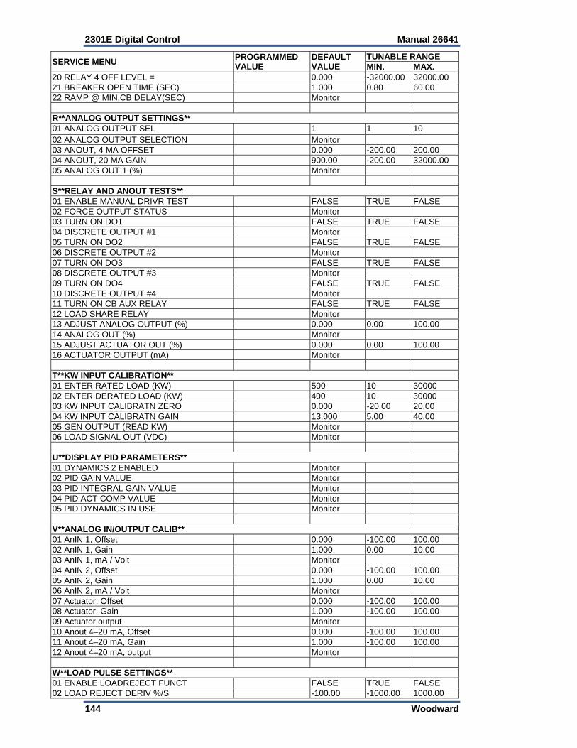
2301E Digital Control Manual 26641
144 Woodward
SERVICE MENU PROGRAMMED VALUE
DEFAULT VALUE
TUNABLE RANGE MIN. MAX.
20 RELAY 4 OFF LEVEL = 0.000 -32000.00 32000.00 21 BREAKER OPEN TIME (SEC) 1.000 0.80 60.00 22 RAMP @ MIN,CB DELAY(SEC) Monitor R**ANALOG OUTPUT SETTINGS** 01 ANALOG OUTPUT SEL 1 1 10 02 ANALOG OUTPUT SELECTION Monitor 03 ANOUT, 4 MA OFFSET 0.000 -200.00 200.00 04 ANOUT, 20 MA GAIN 900.00 -200.00 32000.00 05 ANALOG OUT 1 (%) Monitor S**RELAY AND ANOUT TESTS** 01 ENABLE MANUAL DRIVR TEST FALSE TRUE FALSE 02 FORCE OUTPUT STATUS Monitor 03 TURN ON DO1 FALSE TRUE FALSE 04 DISCRETE OUTPUT #1 Monitor 05 TURN ON DO2 FALSE TRUE FALSE 06 DISCRETE OUTPUT #2 Monitor 07 TURN ON DO3 FALSE TRUE FALSE 08 DISCRETE OUTPUT #3 Monitor 09 TURN ON DO4 FALSE TRUE FALSE 10 DISCRETE OUTPUT #4 Monitor 11 TURN ON CB AUX RELAY FALSE TRUE FALSE 12 LOAD SHARE RELAY Monitor 13 ADJUST ANALOG OUTPUT (%) 0.000 0.00 100.00 14 ANALOG OUT (%) Monitor 15 ADJUST ACTUATOR OUT (%) 0.000 0.00 100.00 16 ACTUATOR OUTPUT (mA) Monitor T**KW INPUT CALIBRATION**01 ENTER RATED LOAD (KW) 500 10 30000 02 ENTER DERATED LOAD (KW) 400 10 30000 03 KW INPUT CALIBRATN ZERO 0.000 -20.00 20.00 04 KW INPUT CALIBRATN GAIN 13.000 5.00 40.00 05 GEN OUTPUT (READ KW) Monitor 06 LOAD SIGNAL OUT (VDC) Monitor U**DISPLAY PID PARAMETERS** 01 DYNAMICS 2 ENABLED Monitor 02 PID GAIN VALUE Monitor 03 PID INTEGRAL GAIN VALUE Monitor 04 PID ACT COMP VALUE Monitor 05 PID DYNAMICS IN USE Monitor V**ANALOG IN/OUTPUT CALIB** 01 AnIN 1, Offset 0.000 -100.00 100.00 02 AnIN 1, Gain 1.000 0.00 10.00 03 AnIN 1, mA / Volt Monitor 04 AnIN 2, Offset 0.000 -100.00 100.00 05 AnIN 2, Gain 1.000 0.00 10.00 06 AnIN 2, mA / Volt Monitor 07 Actuator, Offset 0.000 -100.00 100.00 08 Actuator, Gain 1.000 -100.00 100.00 09 Actuator output Monitor 10 Anout 4–20 mA, Offset 0.000 -100.00 100.00 11 Anout 4–20 mA, Gain 1.000 -100.00 100.00 12 Anout 4–20 mA, output Monitor W**LOAD PULSE SETTINGS**01 ENABLE LOADREJECT FUNCT FALSE TRUE FALSE 02 LOAD REJECT DERIV %/S -100.00 -1000.00 1000.00

Manual 26641 2301E Digital Control
Woodward 145
SERVICE MENU PROGRAMMED VALUE
DEFAULT VALUE
TUNABLE RANGEMIN. MAX.
03 LD REJECT MULT ACT %/S 1.00 -100.00 100.0004 LD REJ RECOVER RATE %/S 0.00 0.00 1000.0005 ENABLE LOAD PULSE FUNCT FALSE TRUE FALSE 06 LD PULSE DERIV %/S 100.00 -1000.00 1000.0007 LD PULSE MULT ACT %/S 1.00 -100.00 100.0008 LD PUL RECOVER RATE %/S 1000.00 0.00 1000.00 X**ADAPTIVE FILTER SET** 01 ADAPTIVE FILTER ENABLE TRUE TRUE FALSE01 ADAPTIVE FILTER GAIN 0.25 0.01 1.00 Y**APPLICATION INFO** 01 APP SOFTWARE NUMBER Monitor 02 APP SOFTWARE REVISION Monitor 03 APPLICATION NAME Monitor Z**COMM PORTS** 01 ENABLE MODBUS CONTROL FALSE TRUE FALSE02 PORT 1 FAIL Monitor 03 PORT 1 BAUD RATE 10 1 1004 PORT 1 BAUD RATE IS SET FOR: Monitor 05 PORT 1 DATA BITS 2 1 206 PORT 1 DATA BITS ARE SET FOR: Monitor 07 PORT 1 STOP BITS 1 1 308 PORT 1 STOP BITS ARE SET FOR: Monitor 09 PORT 1 PARITY 1 1 310 PORT 1 PARITY IS SET FOR: Monitor 11 PORT 2 SELECT (MODBUS OR DATALOG)
1 1 2
12 PORT 2 IS SELECTED FOR: Monitor 13 PORT 2 FAIL Monitor 14 PORT 2 BAUD RATE 10 1 1015 PORT 2 BAUD RATE IS SET FOR: Monitor 16 PORT 2 DATA BITS 2 1 217 PORT 2 DATA BITS ARE SET FOR: Monitor 18 PORT 2 STOP BITS 1 1 319 PORT 2 STOP BITS ARE SET FOR: Monitor 20 PORT 2 PARITY 1 1 321 PORT 2 PARITY IS SET FOR: Monitor 22 PORT 2 TIMEOUT 5 0 10023 PORT 2 ADDRESS 1 1 24724 DIVIDE MODBUS REMOTE SPEED BY 10 FALSE TRUE FALSE25 PORT 2 LINK ERROR Monitor 26 PORT 2 EXCEPTION ERROR Monitor 27 PORT 2 TOTAL EXCEP ERRORS Monitor 28 ENABLE ANALOG INPUT W/MODBUS FALSE TRUE FALSE

2301E Digital Control Manual 26641
146 Woodward
Appendix B. PID Examples
This is a list of some engines that this control was installed on, and the associated PID (Gain, Reset, and Actuator Compensation) values that were tuned in the control.
These values are given for reference only for initial start-up. An improperly calibrated control could cause an overspeed or other damage to the prime mover.
Be prepared to make an emergency shutdown when starting the engine, to protect against runaway or overspeed with possible personal injury, loss of life, or property damage.
This list only contains a small sample of engines. Your engine make and model may not be listed. If you want to put the PID values for your engine in this manual, please contact Woodward.
Engine Type Application Number of Cylinders
Rated Speed (rpm)
Number of Teeth
SpeedSensor
Selected
Gain Value
Reset Value
Act. Com. Value
Clark TLA-6
(Nat. Gas)
Compressor Drive
6 300 360 5 0.5 0.16 0.1
DeLaval Enterprise
DSRV -16 -4 (Diesel)
Power Generation
16 450 60 5 3.5 2.4 0.2
Caterpillar 3304
(Diesel)
Power Generation
4 1800 156 1 20.0 0.4 0.2
Detroit Diesel 471-T
(Diesel)
Power Generation
4 1800 118 1 15.0 0.5 0.2
Table B-1. PID Examples
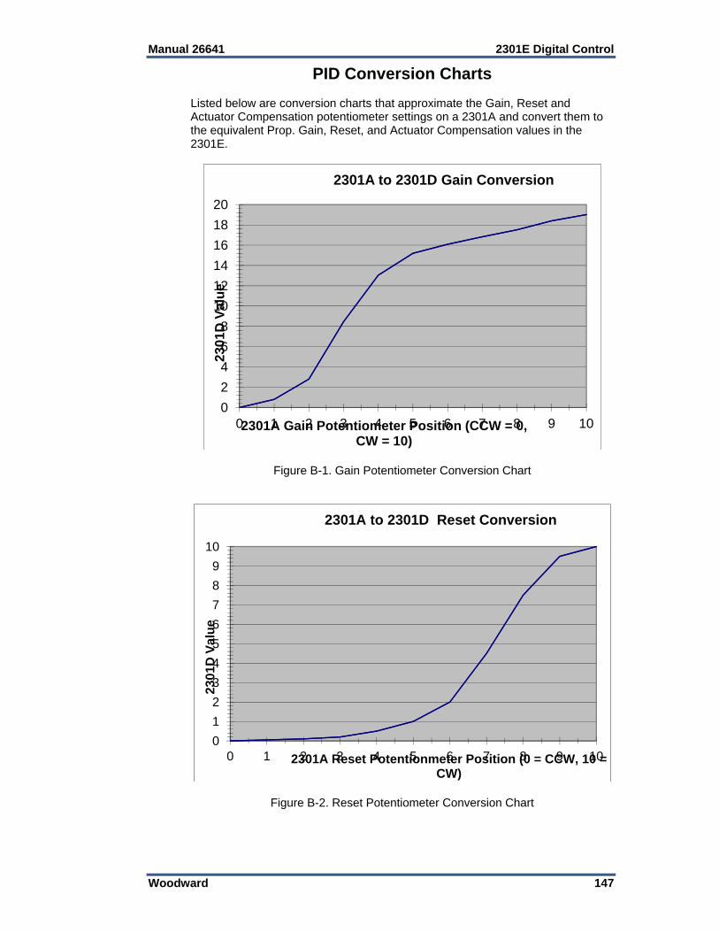
Manual 26641 2301E Digital Control
Woodward 147
PID Conversion Charts Listed below are conversion charts that approximate the Gain, Reset and Actuator Compensation potentiometer settings on a 2301A and convert them to the equivalent Prop. Gain, Reset, and Actuator Compensation values in the 2301E.
Figure B-1. Gain Potentiometer Conversion Chart
Figure B-2. Reset Potentiometer Conversion Chart
0
2
4
6
8
10
12
14
16
18
20
0 1 2 3 4 5 6 7 8 9 10
2301
D V
alu
e
2301A Gain Potentiometer Position (CCW = 0, CW = 10)
2301A to 2301D Gain Conversion
0
1
2
3
4
5
6
7
8
9
10
0 1 2 3 4 5 6 7 8 9 10
2301
D V
alu
e
2301A Reset Potentionmeter Position (0 = CCW, 10 = CW)
2301A to 2301D Reset Conversion
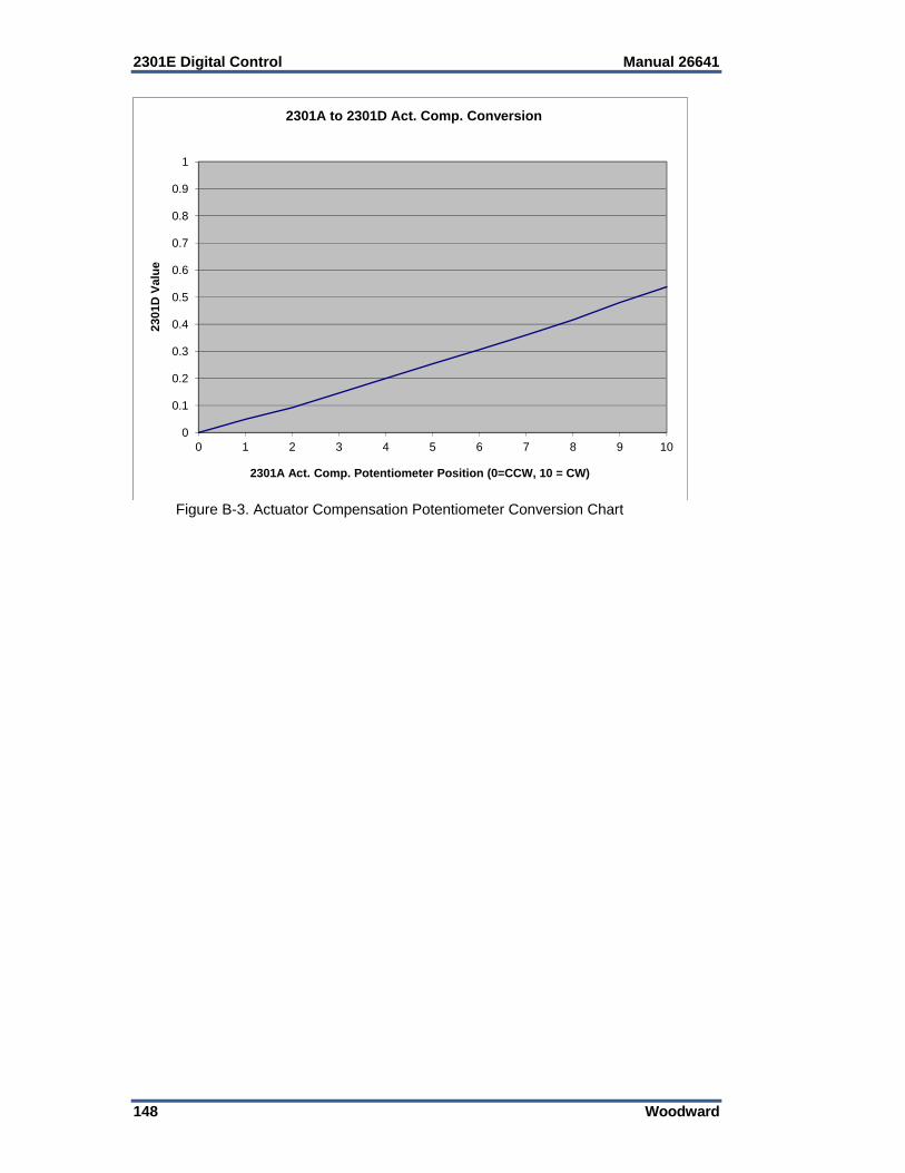
2301E Digital Control Manual 26641
148 Woodward
Figure B-3. Actuator Compensation Potentiometer Conversion Chart
0
0.1
0.2
0.3
0.4
0.5
0.6
0.7
0.8
0.9
1
0 1 2 3 4 5 6 7 8 9 10
2301
D V
alu
e
2301A Act. Comp. Potentiometer Position (0=CCW, 10 = CW)
2301A to 2301D Act. Comp. Conversion
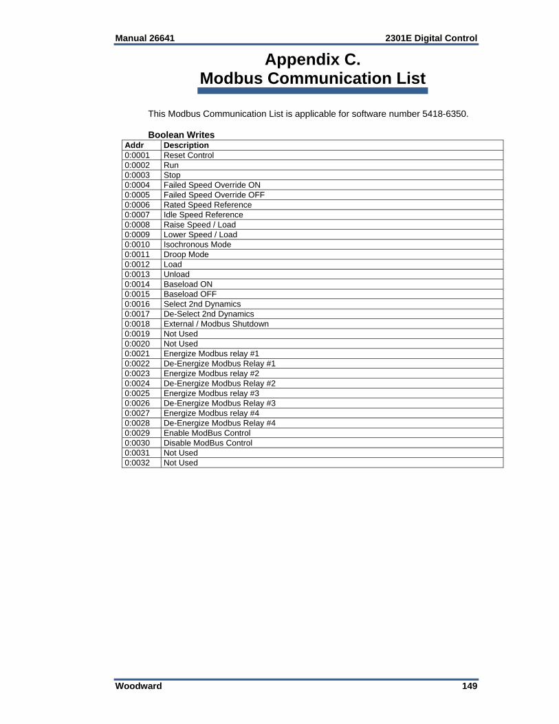
Manual 26641 2301E Digital Control
Woodward 149
Appendix C. Modbus Communication List
This Modbus Communication List is applicable for software number 5418-6350. Boolean Writes
Addr Description 0:0001 Reset Control 0:0002 Run 0:0003 Stop 0:0004 Failed Speed Override ON0:0005 Failed Speed Override OFF0:0006 Rated Speed Reference0:0007 Idle Speed Reference0:0008 Raise Speed / Load0:0009 Lower Speed / Load0:0010 Isochronous Mode0:0011 Droop Mode 0:0012 Load 0:0013 Unload 0:0014 Baseload ON 0:0015 Baseload OFF 0:0016 Select 2nd Dynamics0:0017 De-Select 2nd Dynamics0:0018 External / Modbus Shutdown0:0019 Not Used 0:0020 Not Used 0:0021 Energize Modbus relay #10:0022 De-Energize Modbus Relay #10:0023 Energize Modbus relay #20:0024 De-Energize Modbus Relay #20:0025 Energize Modbus relay #30:0026 De-Energize Modbus Relay #30:0027 Energize Modbus relay #40:0028 De-Energize Modbus Relay #40:0029 Enable ModBus Control 0:0030 Disable ModBus Control 0:0031 Not Used 0:0032 Not Used
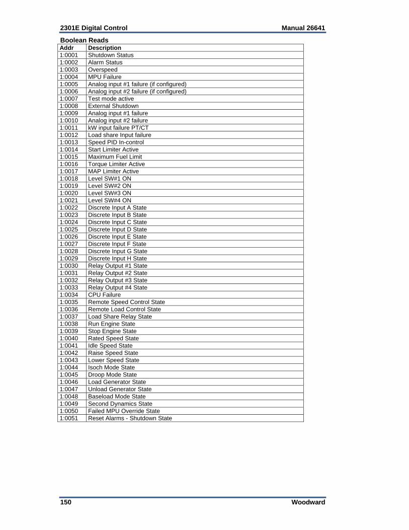
2301E Digital Control Manual 26641
150 Woodward
Boolean Reads Addr Description 1:0001 Shutdown Status 1:0002 Alarm Status1:0003 Overspeed 1:0004 MPU Failure 1:0005 Analog input #1 failure (if configured)1:0006 Analog input #2 failure (if configured)1:0007 Test mode active 1:0008 External Shutdown 1:0009 Analog input #1 failure 1:0010 Analog input #2 failure 1:0011 kW input failure PT/CT 1:0012 Load share Input failure 1:0013 Speed PID In-control 1:0014 Start Limiter Active 1:0015 Maximum Fuel Limit 1:0016 Torque Limiter Active 1:0017 MAP Limiter Active 1:0018 Level SW#1 ON 1:0019 Level SW#2 ON 1:0020 Level SW#3 ON 1:0021 Level SW#4 ON 1:0022 Discrete Input A State 1:0023 Discrete Input B State 1:0024 Discrete Input C State 1:0025 Discrete Input D State 1:0026 Discrete Input E State 1:0027 Discrete Input F State 1:0028 Discrete Input G State 1:0029 Discrete Input H State 1:0030 Relay Output #1 State 1:0031 Relay Output #2 State 1:0032 Relay Output #3 State 1:0033 Relay Output #4 State 1:0034 CPU Failure 1:0035 Remote Speed Control State 1:0036 Remote Load Control State 1:0037 Load Share Relay State 1:0038 Run Engine State 1:0039 Stop Engine State 1:0040 Rated Speed State 1:0041 Idle Speed State 1:0042 Raise Speed State 1:0043 Lower Speed State 1:0044 Isoch Mode State 1:0045 Droop Mode State 1:0046 Load Generator State 1:0047 Unload Generator State 1:0048 Baseload Mode State 1:0049 Second Dynamics State 1:0050 Failed MPU Override State 1:0051 Reset Alarms - Shutdown State
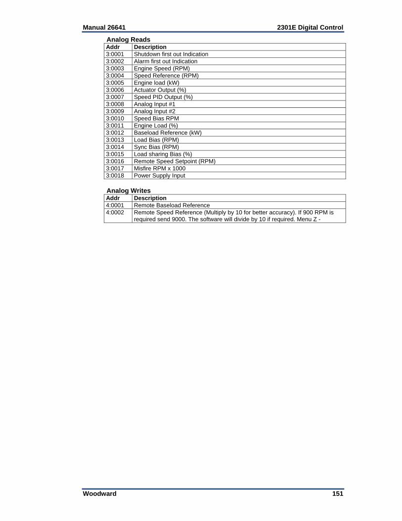
Manual 26641 2301E Digital Control
Woodward 151
Analog Reads Addr Description 3:0001 Shutdown first out Indication3:0002 Alarm first out Indication3:0003 Engine Speed (RPM)3:0004 Speed Reference (RPM)3:0005 Engine load (kW)3:0006 Actuator Output (%)3:0007 Speed PID Output (%)3:0008 Analog Input #13:0009 Analog Input #23:0010 Speed Bias RPM3:0011 Engine Load (%)3:0012 Baseload Reference (kW)3:0013 Load Bias (RPM)3:0014 Sync Bias (RPM)3:0015 Load sharing Bias (%)3:0016 Remote Speed Setpoint (RPM) 3:0017 Misfire RPM x 1000 3:0018 Power Supply Input Analog Writes Addr Description 4:0001 Remote Baseload Reference4:0002 Remote Speed Reference (Multiply by 10 for better accuracy). If 900 RPM is
required send 9000. The software will divide by 10 if required. Menu Z -
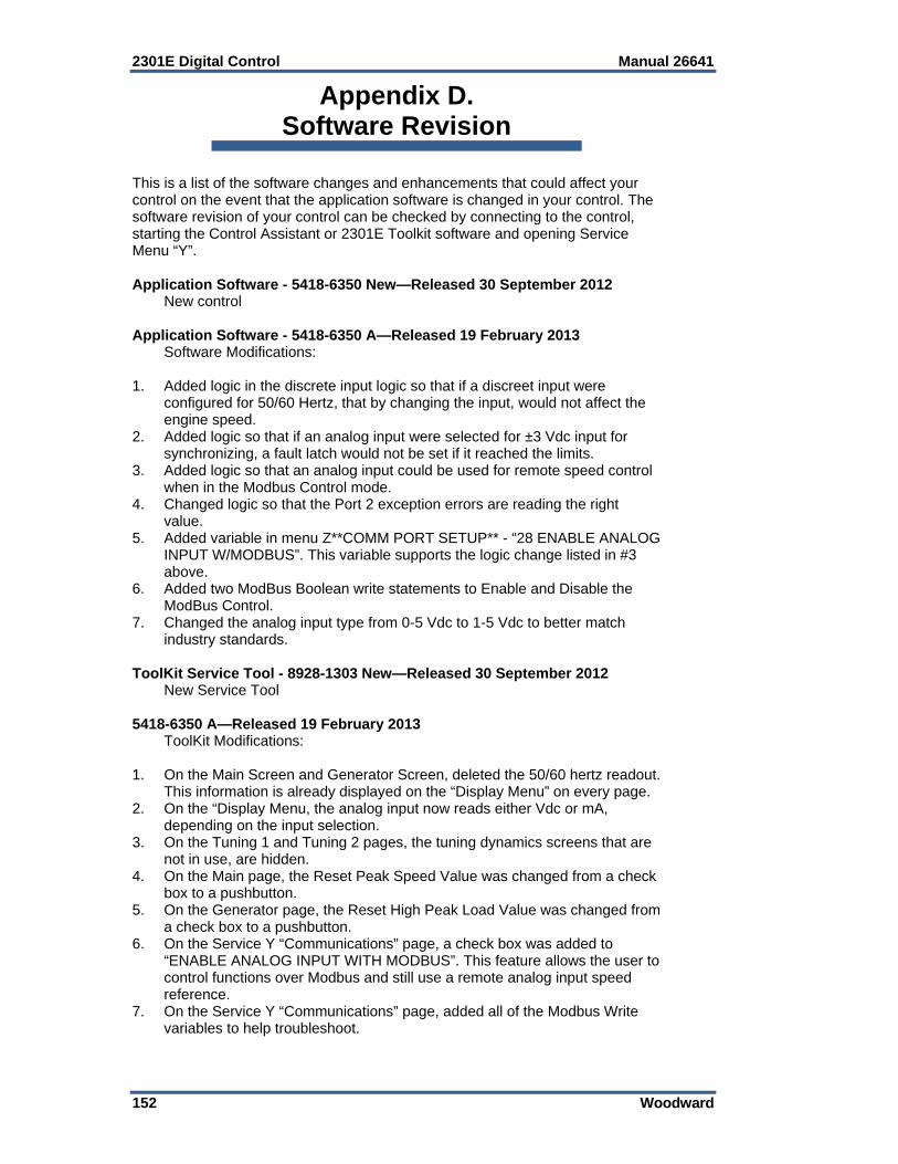
2301E Digital Control Manual 26641
152 Woodward
Appendix D. Software Revision
This is a list of the software changes and enhancements that could affect your control on the event that the application software is changed in your control. The software revision of your control can be checked by connecting to the control, starting the Control Assistant or 2301E Toolkit software and opening Service Menu “Y”. Application Software - 5418-6350 New—Released 30 September 2012 New control Application Software - 5418-6350 A—Released 19 February 2013 Software Modifications: 1. Added logic in the discrete input logic so that if a discreet input were
configured for 50/60 Hertz, that by changing the input, would not affect the engine speed.
2. Added logic so that if an analog input were selected for ±3 Vdc input for synchronizing, a fault latch would not be set if it reached the limits.
3. Added logic so that an analog input could be used for remote speed control when in the Modbus Control mode.
4. Changed logic so that the Port 2 exception errors are reading the right value.
5. Added variable in menu Z**COMM PORT SETUP** - “28 ENABLE ANALOG INPUT W/MODBUS”. This variable supports the logic change listed in #3 above.
6. Added two ModBus Boolean write statements to Enable and Disable the ModBus Control.
7. Changed the analog input type from 0-5 Vdc to 1-5 Vdc to better match industry standards.
ToolKit Service Tool - 8928-1303 New—Released 30 September 2012 New Service Tool 5418-6350 A—Released 19 February 2013 ToolKit Modifications: 1. On the Main Screen and Generator Screen, deleted the 50/60 hertz readout.
This information is already displayed on the “Display Menu” on every page. 2. On the “Display Menu, the analog input now reads either Vdc or mA,
depending on the input selection. 3. On the Tuning 1 and Tuning 2 pages, the tuning dynamics screens that are
not in use, are hidden. 4. On the Main page, the Reset Peak Speed Value was changed from a check
box to a pushbutton. 5. On the Generator page, the Reset High Peak Load Value was changed from
a check box to a pushbutton. 6. On the Service Y “Communications” page, a check box was added to
“ENABLE ANALOG INPUT WITH MODBUS”. This feature allows the user to control functions over Modbus and still use a remote analog input speed reference.
7. On the Service Y “Communications” page, added all of the Modbus Write variables to help troubleshoot.
Manual 26641 2301E Digital Control
Woodward 153
Application Software - 5418-6350 B—Released 30 June 2013 Software Modifications: Fixed an issue where the soft loading feature was working incorrectly. The issue was that if the Load Contact Input and the CB Aux. Contact Input were closed simultaneously, the load would immediately jump to the load share level. The soft load ramp was ignored. If the Load Contact were closed shortly after the CB Aux. contact, the feature worked properly. The software was changed to correct this issue. The soft load feature now works if the Load Contact is closed before the CB Aux. Contact. Application Software - 5418-6350 C—Released 29 July 2013 Software Modifications: Actuator Compensation #1 and Actuator Compensation #2 adjustments were swapped. In order to adjust Actuator Compensation #1, Actuator Compensation #2 had to be adjusted in the second dynamics menu. In order to adjust Actuator Compensation #2, Actuator Compensation #1 had to be adjusted in the first dynamics menu. Service Bulletin 01586 was released to explain the issue. No other changes were made.

2301E Digital Control Manual 26641
154 Woodward
Appendix E. Printing Out a Datalog
The Control Assistant software can be used to collect a datalog from the 2301E. The datalog starts collecting information as soon as a shutdown occurs and will collect 8.0 seconds of information. The information gathered is:
Shutdown Engine Speed Speed Reference Fuel Demand Generator Load Load Sharing Voltage Analog Input #1 Analog Input #2
Here are the steps for downloading the Datalog from the 2301E after a shutdown has occurred or if a manual Datalog stop was executed. 1) Using two computers or a computer with two serial ports, connect a cable to
the RS-232 port to one of the computers and a cable from the RS-422 port to the other computer. The RS-232 cable shall be a null modem cable, the RS-422 cable must have a RS-422 to RS-232 converter on it.
2) Start up Control Assistant software on the computer connected to the RS-232. Click on the New WinPanel Icon and connect using Servlink OPC Server. Click on the “Q” icon which will generate a new Quick Service / Configure Sheets.
3) Scroll to the right and find Service Menu Z**COMM PORTS**. Menu number 11 PORT 2 SELECT (MODBUS OR DATALOG) should be changed to a 2. Menu number 12 PORT 2 IS SELECTED FOR: should say Datalog.
4) Scroll back to SERVICE C**SHUTDOWNS** service menu. 5) On the computer that is connected to the RS-422 port, also open up the
Control Assistant software. Select Transfer and Receive Datalog. Select the communication protocol; the port that you are connected to, baud rate, data bits, parity and stop bits and select OK.
6) Select a file location on your computer where this file will be stored. It is now waiting for the file to be received.
7) Go back to the other computer and under the Service Menu – C**Shutdowns**, number 12 PRINT OUT DATALOG, select True then False. The password for tuning is 1112.
8) On the other computer, you should start seeing the file being downloaded. It takes a few seconds.
9) Go to File \ Open and locate the file that you just created. It will open up a Graph Properties window. Under the Variable list on the left side, either double click or drag and drop the information that want displayed and select OK.
10) If it is not displayed correctly, the Scale (Low) and Scale (High) towards the bottom might have to be adjusted. Swipe across and type in a low and high number for the speed.

Manual 26641 2301E Digital Control
Woodward 155
Appendix F. Quick Engine Start Guide
This quick start guide will allow the user to quickly configure the 2301E with minimal settings for simple speed control. It uses the 2301E Toolkit Service Tool to configure the control. 1. Download the 2301E Toolkit Service Tool and the SOS Servlink OPC
Server software from www.woodward.com/software and install it on your computer.
2. Connect a Null Modem cable from the computer to the RS-232 port on the 2301E.
3. Start the Service Tool and Click on Connect. The Main Screen will display once connected.
4. To configure the setpoints, click on the “CONFIGURATION” button. Click on the “PRESS TO EDIT ALL OF THE CONFIGURATION VALUES” button. Verify that the engine is shutdown!
5. There are four configuration menu’s, available from the pull down list at the top of this menu. a. Speed Control Functions b. Engine – Generator Control Functions c. Inputs d. Outputs
6. Starting at the “Speed Control Functions” menu, enter the following items: a. Rated Speed 60 Hz Grid speed. This is the synchronous speed of the
generator. 720 RPM, 900 RPM, 1200 RPM, 1800 RPM… b. Overspeed Setting is usually set at 15% above rated speed. c. Leave the rest of the variables at default values. d. Select “Apply” to write these variables to the control.
7. Select the “Engine-Generator Control Functions” menu and enter the following items: a. Number of Gear Teeth b. Number of Cylinders c. Leave the rest of the variables at default values. d. Select “Apply” to write these variables to the control.
8. Select the “Inputs” menu and enter the following items: a. Decide if you are using any of the configurable Discrete Inputs and
what the function of each should be. The default configuration is Discrete Input B = Reset, Discrete Input C = Idle / Rated Speed, and Discrete Input D = Isoch / Droop. If not using any of these, put them at 1 (not used).
b. Select “Apply” to write these variables to the control. 9. Select the “Outputs” menu and enter the following items:
a. Select the “Configured Actuator Type”. If using a Woodward hydro-mechanical actuator, typically the output is 0-200 mA.
b. Select the “Actuator is Direct Acting” or “Actuator is Reverse Acting” to match your type of actuator. Reverse Acting actuator must have a ball-head governor as a back up if you select Reverse Acting.
c. Select “Apply” to write these variables to the control. 10. Select the “MAIN SCREEN”, then select “SERVICE MENU’S. Select the
“SPEED SETTINGS” button. 11. Under the “SPEED SETTINGS” header, input the following items:
a. Raise Speed Limit – Maximum speed allowed from Discrete Input. b. Lower Speed Limit – Minimum speed allowed from Discrete Input. c. Idle Speed d. Leave the rest of the variables at default values.

2301E Digital Control Manual 26641
156 Woodward
12. Select the “Service L” button to set-up the Fuel Limiters. a. Set the “START FUEL LIMIT (%FD) to 50%. This will position the fuel
rack to approximately 50% during cranking. b. Leave the rest of the variables at default values.
13. Select “Device” from the headers at the top of the screen. Select “Save Values”.
14. The engine is ready to be started. Select the “Tuning 1” button and be ready to tune either the “IDLE PROP GAIN 1” or the “RATED PROP GAIN 1”, depending if you are starting in Idle Speed or Rated Speed. If the engine is unstable, lower the gain until stability is achieved.
15. Chapter 6 provides a tuning method to properly tune the engine control for optimum performance.
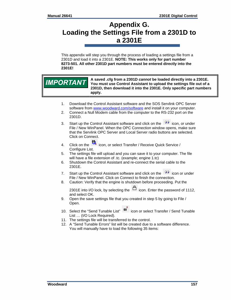
Manual 26641 2301E Digital Control
Woodward 157
Appendix G. Loading the Settings File from a 2301D to
a 2301E This appendix will step you through the process of loading a settings file from a 2301D and load it into a 2301E. NOTE: This works only for part number 8273-501. All other 2301D part numbers must be entered directly into the 2301E!
A saved .cfg from a 2301D cannot be loaded directly into a 2301E. You must use Control Assistant to upload the settings file out of a 2301D, then download it into the 2301E. Only specific part numbers apply.
1. Download the Control Assistant software and the SOS Servlink OPC Server
software from www.woodward.com/software and install it on your computer. 2. Connect a Null Modem cable from the computer to the RS-232 port on the
2301D.
3. Start up the Control Assistant software and click on the icon, or under File / New WinPanel. When the OPC Connection window opens, make sure that the Servlink OPC Server and Local Server radio buttons are selected. Click on Connect.
4. Click on the icon, or select Transfer / Receive Quick Service / Configure List.
5. The settings file will upload and you can save it to your computer. The file will have a file extension of .tc. (example; engine 1.tc)
6. Shutdown the Control Assistant and re-connect the serial cable to the 2301E.
7. Start up the Control Assistant software and click on the icon or under File / New WinPanel. Click on Connect to finish the connection.
8. Caution: Verify that the engine is shutdown before proceeding. Put the
2301E into I/O lock, by selecting the icon. Enter the password of 1112, and select OK.
9. Open the save settings file that you created in step 5 by going to File / Open.
10. Select the “Send Tunable List” icon or select Transfer / Send Tunable List … (I/O Lock Required).
11. The settings file will be transferred to the control. 12. A “Send Tunable Errors” list will be created due to a software difference.
You will manually have to load the following 35 items:

2301E Digital Control Manual 26641
158 Woodward
If you do not go into Control Assistant and manually enter the following items, your engine will not run at the right speed!
13. To manually enter the above values, with the Control Assistant software
running, select the icon, Generate Quick Service / Configure Sheets. Manually go to each menu item listed above and enter in the correct value. The original .cfg file can be opened in MS Excel or Notepad on you computer to verify the numbers.
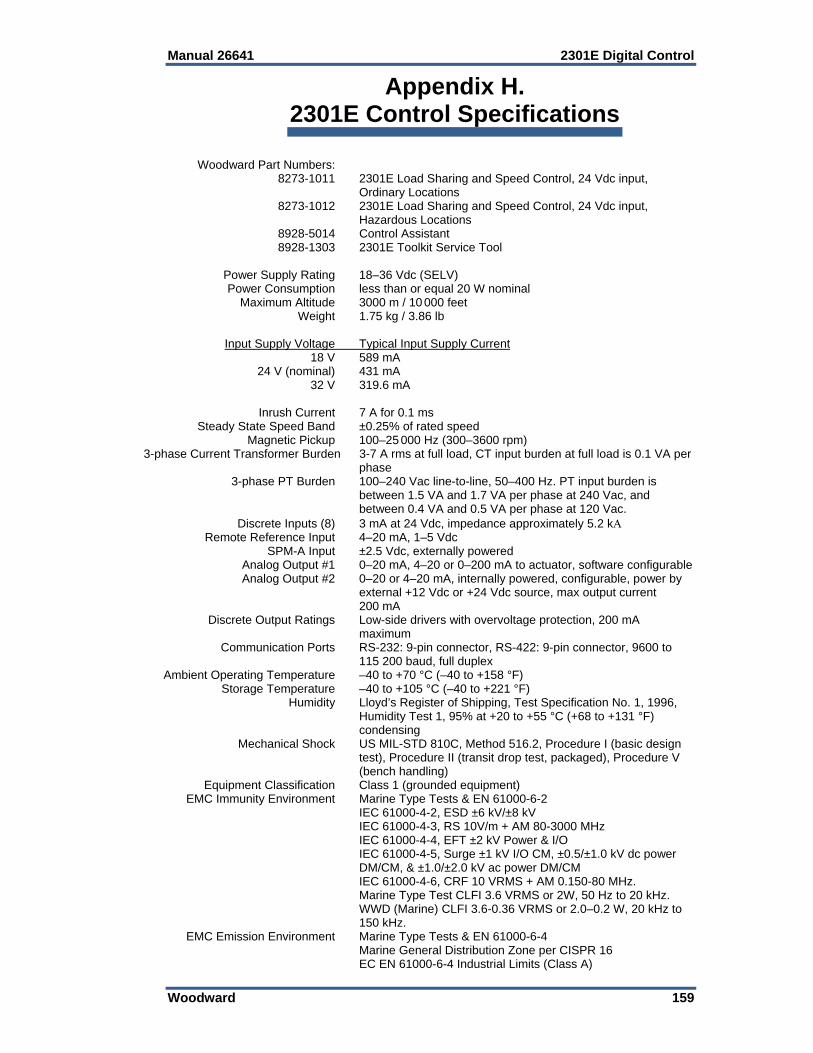
Manual 26641 2301E Digital Control
Woodward 159
Appendix H. 2301E Control Specifications
Woodward Part Numbers: 8273-1011 2301E Load Sharing and Speed Control, 24 Vdc input,
Ordinary Locations 8273-1012 2301E Load Sharing and Speed Control, 24 Vdc input,
Hazardous Locations 8928-5014 Control Assistant 8928-1303 2301E Toolkit Service Tool Power Supply Rating 18–36 Vdc (SELV) Power Consumption less than or equal 20 W nominal Maximum Altitude 3000 m / 10 000 feet Weight 1.75 kg / 3.86 lb Input Supply Voltage Typical Input Supply Current 18 V 589 mA 24 V (nominal) 431 mA 32 V 319.6 mA Inrush Current 7 A for 0.1 ms Steady State Speed Band ±0.25% of rated speed Magnetic Pickup 100–25 000 Hz (300–3600 rpm) 3-phase Current Transformer Burden 3-7 A rms at full load, CT input burden at full load is 0.1 VA per
phase 3-phase PT Burden 100–240 Vac line-to-line, 50–400 Hz. PT input burden is
between 1.5 VA and 1.7 VA per phase at 240 Vac, and between 0.4 VA and 0.5 VA per phase at 120 Vac.
Discrete Inputs (8) 3 mA at 24 Vdc, impedance approximately 5.2 k Remote Reference Input 4–20 mA, 1–5 Vdc SPM-A Input ±2.5 Vdc, externally powered Analog Output #1 0–20 mA, 4–20 or 0–200 mA to actuator, software configurable Analog Output #2 0–20 or 4–20 mA, internally powered, configurable, power by
external +12 Vdc or +24 Vdc source, max output current 200 mA
Discrete Output Ratings Low-side drivers with overvoltage protection, 200 mA maximum
Communication Ports RS-232: 9-pin connector, RS-422: 9-pin connector, 9600 to 115 200 baud, full duplex
Ambient Operating Temperature –40 to +70 °C (–40 to +158 °F) Storage Temperature –40 to +105 °C (–40 to +221 °F) Humidity Lloyd’s Register of Shipping, Test Specification No. 1, 1996,
Humidity Test 1, 95% at +20 to +55 °C (+68 to +131 °F) condensing
Mechanical Shock US MIL-STD 810C, Method 516.2, Procedure I (basic design test), Procedure II (transit drop test, packaged), Procedure V (bench handling)
Equipment Classification Class 1 (grounded equipment) EMC Immunity Environment Marine Type Tests & EN 61000-6-2 IEC 61000-4-2, ESD ±6 kV/±8 kV IEC 61000-4-3, RS 10V/m + AM 80-3000 MHz IEC 61000-4-4, EFT ±2 kV Power & I/O IEC 61000-4-5, Surge ±1 kV I/O CM, ±0.5/±1.0 kV dc power
DM/CM, & ±1.0/±2.0 kV ac power DM/CM IEC 61000-4-6, CRF 10 VRMS + AM 0.150-80 MHz. Marine Type Test CLFI 3.6 VRMS or 2W, 50 Hz to 20 kHz. WWD (Marine) CLFI 3.6-0.36 VRMS or 2.0–0.2 W, 20 kHz to
150 kHz. EMC Emission Environment Marine Type Tests & EN 61000-6-4 Marine General Distribution Zone per CISPR 16 EC EN 61000-6-4 Industrial Limits (Class A)

2301E Digital Control Manual 26641
160 Woodward
Revision History Changes in Revision D— Various corrections to values as marked (pages 2, 21, 22, 69, 70, 77) Added explanation of 5418-6350 C software revision to Appendix D Changes in Revision C— Added new Marine certifications (BV, NKK, CCS) Added product weight Changes in Revision B— Added software update information to Appendixes D & G Changes in Revision A— Various minor updates/corrections as marked Added manual to Service Tool (see page 62) Added Port 2 steps (page 107 and Appendix A) Updated Appendixes C & D Added new Appendixes F & G
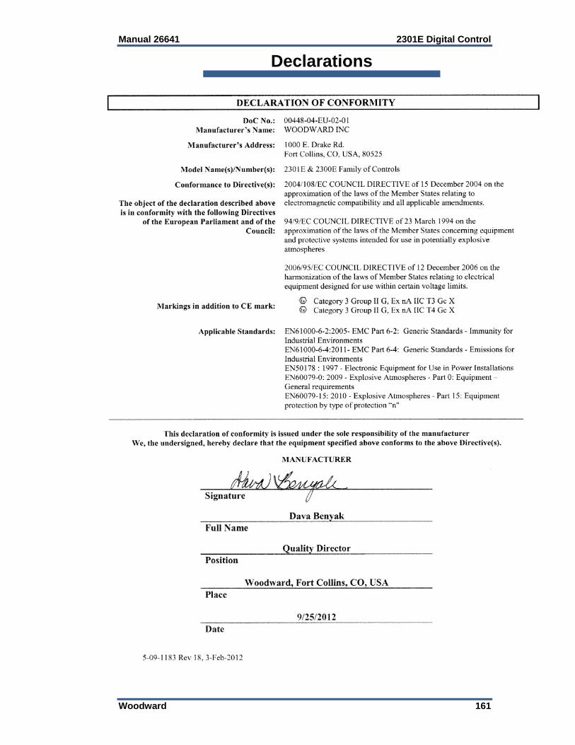
Manual 26641 2301E Digital Control
Woodward 161
Declarations

We appreciate your comments about the content of our publications.
Send comments to: [email protected]
Please reference publication 26641D.
PO Box 1519, Fort Collins CO 80522-1519, USA 1000 East Drake Road, Fort Collins CO 80525, USA Phone +1 (970) 482-5811 Fax +1 (970) 498-3058
Email and Website—www.woodward.com
Woodward has company-owned plants, subsidiaries, and branches, as well as authorized distributors and other authorized service and sales facilities throughout the world.
Complete address / phone / fax / email information for all locations is available on our website.