Embed Size (px)
DESCRIPTION
Practica
Citation preview
© 2015 Cisco and/or its affiliates. All rights reserved. This document is Cisco Public. Page 1 of 13
Lab - Building a Simple Network
Topology
Addressing Table
Device Interface IP Address Subnet Mask
PC-A NIC 192.168.1.10 255.255.255.0
PC-B NIC 192.168.1.11 255.255.255.0
Objectives
Part 1: Set Up the Network Topology (Ethernet only)
Part 2: Configure PC Hosts
Part 3: Configure and Verify Basic Switch Settings
Background / Scenario
Networks are constructed of three major components: hosts, switches, and routers. In this lab, you will build a simple network with two hosts and two switches. You will also configure basic settings including hostname, local passwords, and login banner. Use show commands to display the running configuration, IOS version, and interface status. Use the copy command to save device configurations.
You will apply IP addressing for this lab to the PCs to enable communication between these two devices. Use the ping utility to verify connectivity.
Note: The switches used are Cisco Catalyst 2960s with Cisco IOS Release 15.0(2) (lanbasek9 image). Other switches and Cisco IOS versions can be used. Depending on the model and Cisco IOS version, the commands available and output produced might vary from what is shown in the labs.
Note: Make sure that the switches have been erased and have no startup configurations. Refer to Appendix A for the procedure to initialize and reload a switch.
Required Resources
2 Switches (Cisco 2960 with Cisco IOS Release 15.0(2) lanbasek9 image or comparable)
2 PCs (Windows 7 or 8 with terminal emulation program, such as Tera Term)
Console cables to configure the Cisco IOS devices via the console ports
Lab - Building a Simple Network
© 2015 Cisco and/or its affiliates. All rights reserved. This document is Cisco Public. Page 2 of 13
Ethernet cables as shown in the topology
Part 1: Set Up the Network Topology (Ethernet only)
In Part 1, you will cable the devices together according to the network topology.
Step 1: Power on the devices.
Power on all devices in the topology. The switches do not have a power switch; they will power on as soon as you plug in the power cord.
Step 2: Connect the two switches.
Connect one end of an Ethernet cable to F0/1 on S1 and the other end of the cable to F0/1 on S2. You should see the lights for F0/1 on both switches turn amber and then green. This indicates that the switches have been connected correctly.
Step 3: Connect the PCs to their respective switches.
a. Connect one end of the second Ethernet cable to the NIC port on PC-A. Connect the other end of the cable to F0/6 on S1. After connecting the PC to the switch, you should see the light for F0/6 turn amber and then green, indicating that PC-A has been connected correctly.
b. Connect one end of the last Ethernet cable to the NIC port on PC-B. Connect the other end of the cable to F0/18 on S2. After connecting the PC to the switch, you should see the light for F0/18 turn amber and then green, indicating that the PC-B has been connected correctly.
Step 4: Visually inspect network connections.
After cabling the network devices, take a moment to carefully verify the connections to minimize the time required to troubleshoot network connectivity issues later.
Part 2: Configure PC Hosts
Step 1: Configure static IP address information on the PCs.
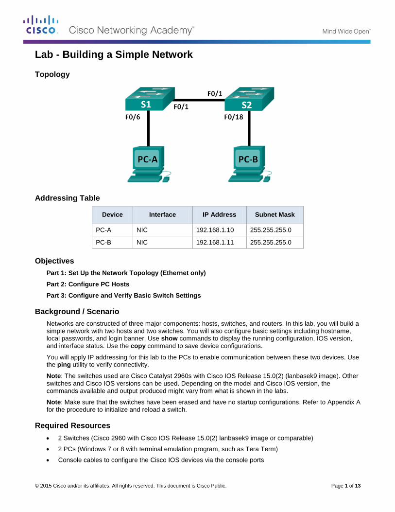
a. Click the Windows Start icon and then select Control Panel.
Lab - Building a Simple Network
© 2015 Cisco and/or its affiliates. All rights reserved. This document is Cisco Public. Page 3 of 13
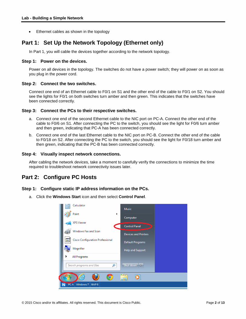
b. In the Network and Internet section, click the View network status and tasks link.
Note: If the Control Panel displays a list of icons, click the drop-down option next to the View by: and change this option to display by Category.
c. In the left pane of the Network and Sharing Center window, click the Change adapter settings link.
Lab - Building a Simple Network
© 2015 Cisco and/or its affiliates. All rights reserved. This document is Cisco Public. Page 4 of 13
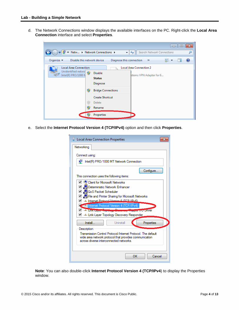
d. The Network Connections window displays the available interfaces on the PC. Right-click the Local Area Connection interface and select Properties.
e. Select the Internet Protocol Version 4 (TCP/IPv4) option and then click Properties.
Note: You can also double-click Internet Protocol Version 4 (TCP/IPv4) to display the Properties window.
Lab - Building a Simple Network
© 2015 Cisco and/or its affiliates. All rights reserved. This document is Cisco Public. Page 5 of 13
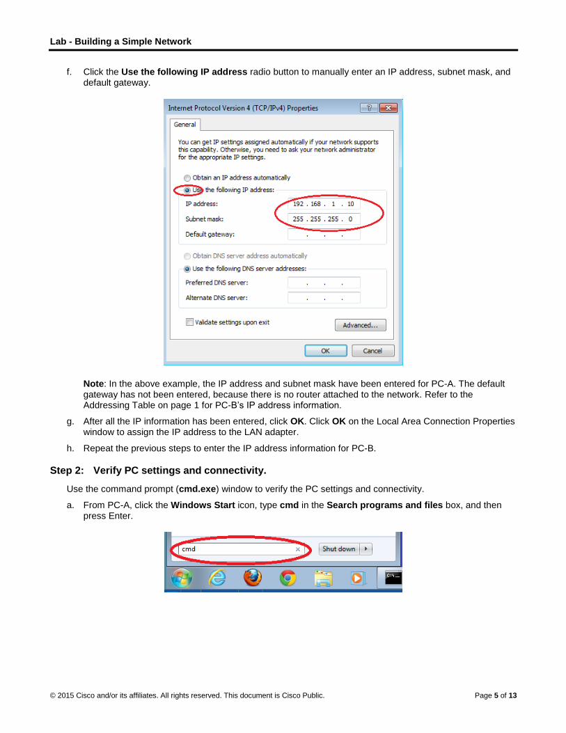
f. Click the Use the following IP address radio button to manually enter an IP address, subnet mask, and default gateway.
Note: In the above example, the IP address and subnet mask have been entered for PC-A. The default gateway has not been entered, because there is no router attached to the network. Refer to the Addressing Table on page 1 for PC-B’s IP address information.
g. After all the IP information has been entered, click OK. Click OK on the Local Area Connection Properties window to assign the IP address to the LAN adapter.
h. Repeat the previous steps to enter the IP address information for PC-B.
Step 2: Verify PC settings and connectivity.
Use the command prompt (cmd.exe) window to verify the PC settings and connectivity.
a. From PC-A, click the Windows Start icon, type cmd in the Search programs and files box, and then press Enter.
Lab - Building a Simple Network
© 2015 Cisco and/or its affiliates. All rights reserved. This document is Cisco Public. Page 6 of 13
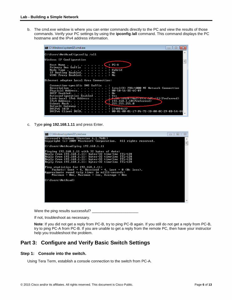
b. The cmd.exe window is where you can enter commands directly to the PC and view the results of those commands. Verify your PC settings by using the ipconfig /all command. This command displays the PC hostname and the IPv4 address information.
c. Type ping 192.168.1.11 and press Enter.
Were the ping results successful? ______________________
If not, troubleshoot as necessary.
Note: If you did not get a reply from PC-B, try to ping PC-B again. If you still do not get a reply from PC-B, try to ping PC-A from PC-B. If you are unable to get a reply from the remote PC, then have your instructor help you troubleshoot the problem.
Part 3: Configure and Verify Basic Switch Settings
Step 1: Console into the switch.
Using Tera Term, establish a console connection to the switch from PC-A.
Lab - Building a Simple Network
© 2015 Cisco and/or its affiliates. All rights reserved. This document is Cisco Public. Page 7 of 13
Step 2: Enter privileged EXEC mode.
You can access all switch commands in privileged EXEC mode. The privileged EXEC command set includes those commands contained in user EXEC mode, as well as the configure command through which access to the remaining command modes are gained. Enter privileged EXEC mode by entering the enable command.
Switch> enable
Switch#
The prompt changed from Switch> to Switch# which indicates privileged EXEC mode.
Step 3: Enter configuration mode.
Use the configuration terminal command to enter configuration mode.
Switch# configure terminal
Enter configuration commands, one per line. End with CNTL/Z.
Switch(config)#
The prompt changed to reflect global configuration mode.
Step 4: Give the switch a name.
Use the hostname command to change the switch name to S1.
Switch(config)# hostname S1
S1(config)#
Step 5: Prevent unwanted DNS lookups.
To prevent the switch from attempting to translate incorrectly entered commands as though they were hostnames, disable the Domain Name System (DNS) lookup.
S1(config)# no ip domain-lookup
S1(config)#
Step 6: Enter local passwords.
To prevent unauthorized access to the switch, passwords must be configured.
S1(config)# enable secret class
S1(config)# line con 0
S1(config-line)# password cisco
S1(config-line)# login
S1(config-line)# exit
S1(config)#
Step 7: Enter a login MOTD banner.
A login banner, known as the message of the day (MOTD) banner, should be configured to warn anyone accessing the switch that unauthorized access will not be tolerated.
The banner motd command requires the use of delimiters to identify the content of the banner message. The delimiting character can be any character as long as it does not occur in the message. For this reason, symbols, such as the #, are often used.
Lab - Building a Simple Network
© 2015 Cisco and/or its affiliates. All rights reserved. This document is Cisco Public. Page 8 of 13
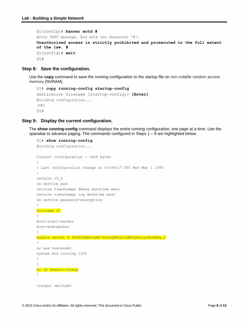
S1(config)# banner motd #
Enter TEXT message. End with the character '#'.
Unauthorized access is strictly prohibited and prosecuted to the full extent
of the law. #
S1(config)# exit
S1#
Step 8: Save the configuration.
Use the copy command to save the running configuration to the startup file on non-volatile random access memory (NVRAM).
S1# copy running-config startup-config
Destination filename [startup-config]? [Enter]
Building configuration...
[OK]
S1#
Step 9: Display the current configuration.
The show running-config command displays the entire running configuration, one page at a time. Use the spacebar to advance paging. The commands configured in Steps 1 – 8 are highlighted below.
S1# show running-config
Building configuration...
Current configuration : 1409 bytes
!
! Last configuration change at 03:49:17 UTC Mon Mar 1 1993
!
version 15.0
no service pad
service timestamps debug datetime msec
service timestamps log datetime msec
no service password-encryption
!
hostname S1
!
boot-start-marker
boot-end-marker
!
enable secret 4 06YFDUHH61wAE/kLkDq9BGho1QM5EnRtoyr8cHAUg.2
!
no aaa new-model
system mtu routing 1500
!
!
no ip domain-lookup
!
<output omitted>
Lab - Building a Simple Network
© 2015 Cisco and/or its affiliates. All rights reserved. This document is Cisco Public. Page 9 of 13
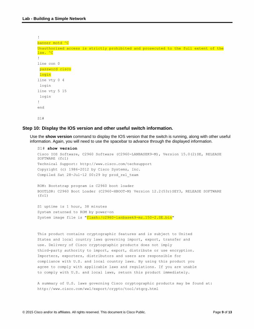
!
banner motd ^C
Unauthorized access is strictly prohibited and prosecuted to the full extent of the
law. ^C
!
line con 0
password cisco
login
line vty 0 4
login
line vty 5 15
login
!
end
S1#
Step 10: Display the IOS version and other useful switch information.
Use the show version command to display the IOS version that the switch is running, along with other useful information. Again, you will need to use the spacebar to advance through the displayed information.
S1# show version
Cisco IOS Software, C2960 Software (C2960-LANBASEK9-M), Version 15.0(2)SE, RELEASE
SOFTWARE (fc1)
Technical Support: http://www.cisco.com/techsupport
Copyright (c) 1986-2012 by Cisco Systems, Inc.
Compiled Sat 28-Jul-12 00:29 by prod_rel_team
ROM: Bootstrap program is C2960 boot loader
BOOTLDR: C2960 Boot Loader (C2960-HBOOT-M) Version 12.2(53r)SEY3, RELEASE SOFTWARE
(fc1)
S1 uptime is 1 hour, 38 minutes
System returned to ROM by power-on
System image file is "flash:/c2960-lanbasek9-mz.150-2.SE.bin"
This product contains cryptographic features and is subject to United
States and local country laws governing import, export, transfer and
use. Delivery of Cisco cryptographic products does not imply
third-party authority to import, export, distribute or use encryption.
Importers, exporters, distributors and users are responsible for
compliance with U.S. and local country laws. By using this product you
agree to comply with applicable laws and regulations. If you are unable
to comply with U.S. and local laws, return this product immediately.
A summary of U.S. laws governing Cisco cryptographic products may be found at:
http://www.cisco.com/wwl/export/crypto/tool/stqrg.html
Lab - Building a Simple Network
© 2015 Cisco and/or its affiliates. All rights reserved. This document is Cisco Public. Page 10 of 13
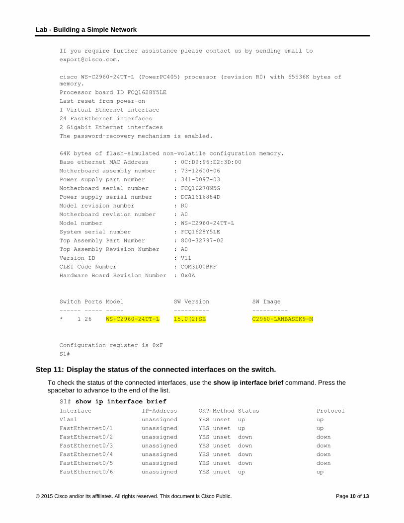
If you require further assistance please contact us by sending email to
cisco WS-C2960-24TT-L (PowerPC405) processor (revision R0) with 65536K bytes of
memory.
Processor board ID FCQ1628Y5LE
Last reset from power-on
1 Virtual Ethernet interface
24 FastEthernet interfaces
2 Gigabit Ethernet interfaces
The password-recovery mechanism is enabled.
64K bytes of flash-simulated non-volatile configuration memory.
Base ethernet MAC Address : 0C:D9:96:E2:3D:00
Motherboard assembly number : 73-12600-06
Power supply part number : 341-0097-03
Motherboard serial number : FCQ16270N5G
Power supply serial number : DCA1616884D
Model revision number : R0
Motherboard revision number : A0
Model number : WS-C2960-24TT-L
System serial number : FCQ1628Y5LE
Top Assembly Part Number : 800-32797-02
Top Assembly Revision Number : A0
Version ID : V11
CLEI Code Number : COM3L00BRF
Hardware Board Revision Number : 0x0A
Switch Ports Model SW Version SW Image
------ ----- ----- ---------- ----------
* 1 26 WS-C2960-24TT-L 15.0(2)SE C2960-LANBASEK9-M
Configuration register is 0xF
S1#
Step 11: Display the status of the connected interfaces on the switch.
To check the status of the connected interfaces, use the show ip interface brief command. Press the spacebar to advance to the end of the list.
S1# show ip interface brief
Interface IP-Address OK? Method Status Protocol
Vlan1 unassigned YES unset up up
FastEthernet0/1 unassigned YES unset up up
FastEthernet0/2 unassigned YES unset down down
FastEthernet0/3 unassigned YES unset down down
FastEthernet0/4 unassigned YES unset down down
FastEthernet0/5 unassigned YES unset down down
FastEthernet0/6 unassigned YES unset up up
Lab - Building a Simple Network
© 2015 Cisco and/or its affiliates. All rights reserved. This document is Cisco Public. Page 11 of 13
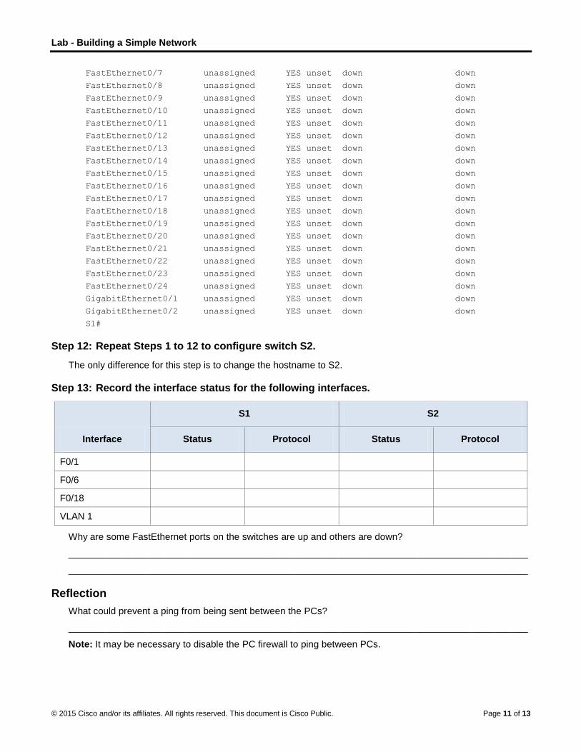
FastEthernet0/7 unassigned YES unset down down
FastEthernet0/8 unassigned YES unset down down
FastEthernet0/9 unassigned YES unset down down
FastEthernet0/10 unassigned YES unset down down
FastEthernet0/11 unassigned YES unset down down
FastEthernet0/12 unassigned YES unset down down
FastEthernet0/13 unassigned YES unset down down
FastEthernet0/14 unassigned YES unset down down
FastEthernet0/15 unassigned YES unset down down
FastEthernet0/16 unassigned YES unset down down
FastEthernet0/17 unassigned YES unset down down
FastEthernet0/18 unassigned YES unset down down
FastEthernet0/19 unassigned YES unset down down
FastEthernet0/20 unassigned YES unset down down
FastEthernet0/21 unassigned YES unset down down
FastEthernet0/22 unassigned YES unset down down
FastEthernet0/23 unassigned YES unset down down
FastEthernet0/24 unassigned YES unset down down
GigabitEthernet0/1 unassigned YES unset down down
GigabitEthernet0/2 unassigned YES unset down down
S1#
Step 12: Repeat Steps 1 to 12 to configure switch S2.
The only difference for this step is to change the hostname to S2.
Step 13: Record the interface status for the following interfaces.
Interface
S1 S2
Status Protocol Status Protocol
F0/1
F0/6
F0/18
VLAN 1
Why are some FastEthernet ports on the switches are up and others are down?
_______________________________________________________________________________________
_______________________________________________________________________________________
Reflection
What could prevent a ping from being sent between the PCs?
_______________________________________________________________________________________
Note: It may be necessary to disable the PC firewall to ping between PCs.
Lab - Building a Simple Network
© 2015 Cisco and/or its affiliates. All rights reserved. This document is Cisco Public. Page 12 of 13
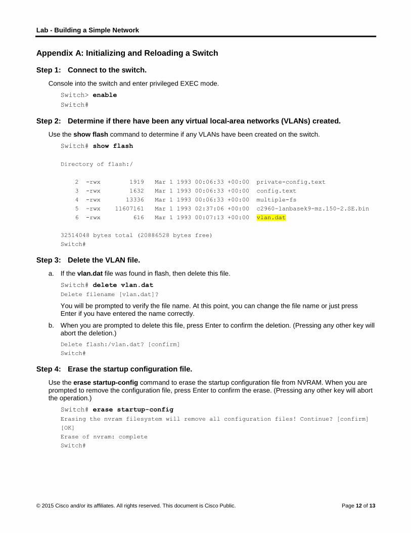
Appendix A: Initializing and Reloading a Switch
Step 1: Connect to the switch.
Console into the switch and enter privileged EXEC mode.
Switch> enable
Switch#
Step 2: Determine if there have been any virtual local-area networks (VLANs) created.
Use the show flash command to determine if any VLANs have been created on the switch.
Switch# show flash
Directory of flash:/
2 -rwx 1919 Mar 1 1993 00:06:33 +00:00 private-config.text
3 -rwx 1632 Mar 1 1993 00:06:33 +00:00 config.text
4 -rwx 13336 Mar 1 1993 00:06:33 +00:00 multiple-fs
5 -rwx 11607161 Mar 1 1993 02:37:06 +00:00 c2960-lanbasek9-mz.150-2.SE.bin
6 -rwx 616 Mar 1 1993 00:07:13 +00:00 vlan.dat
32514048 bytes total (20886528 bytes free)
Switch#
Step 3: Delete the VLAN file.
a. If the vlan.dat file was found in flash, then delete this file.
Switch# delete vlan.dat
Delete filename [vlan.dat]?
You will be prompted to verify the file name. At this point, you can change the file name or just press Enter if you have entered the name correctly.
b. When you are prompted to delete this file, press Enter to confirm the deletion. (Pressing any other key will abort the deletion.)
Delete flash:/vlan.dat? [confirm]
Switch#
Step 4: Erase the startup configuration file.
Use the erase startup-config command to erase the startup configuration file from NVRAM. When you are prompted to remove the configuration file, press Enter to confirm the erase. (Pressing any other key will abort the operation.)
Switch# erase startup-config
Erasing the nvram filesystem will remove all configuration files! Continue? [confirm]
[OK]
Erase of nvram: complete
Switch#
Lab - Building a Simple Network
© 2015 Cisco and/or its affiliates. All rights reserved. This document is Cisco Public. Page 13 of 13
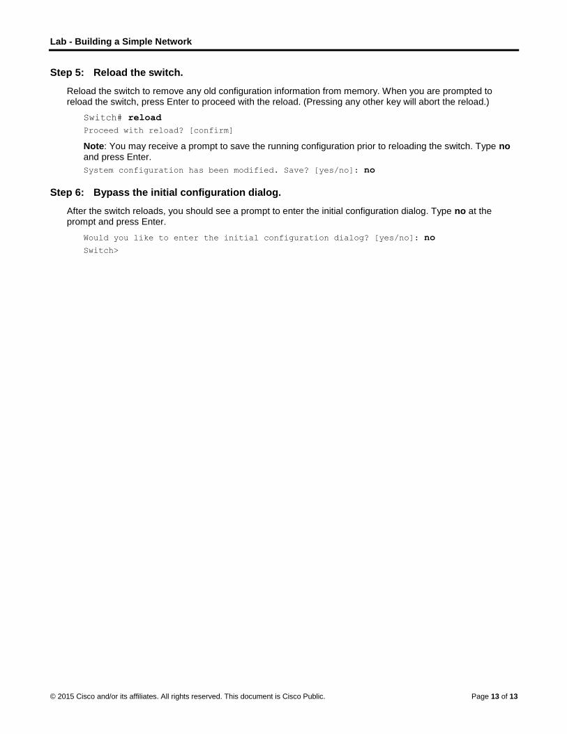
Step 5: Reload the switch.
Reload the switch to remove any old configuration information from memory. When you are prompted to reload the switch, press Enter to proceed with the reload. (Pressing any other key will abort the reload.)
Switch# reload
Proceed with reload? [confirm]
Note: You may receive a prompt to save the running configuration prior to reloading the switch. Type no and press Enter.
System configuration has been modified. Save? [yes/no]: no
Step 6: Bypass the initial configuration dialog.
After the switch reloads, you should see a prompt to enter the initial configuration dialog. Type no at the prompt and press Enter.
Would you like to enter the initial configuration dialog? [yes/no]: no
Switch>