Embed Size (px)
Citation preview
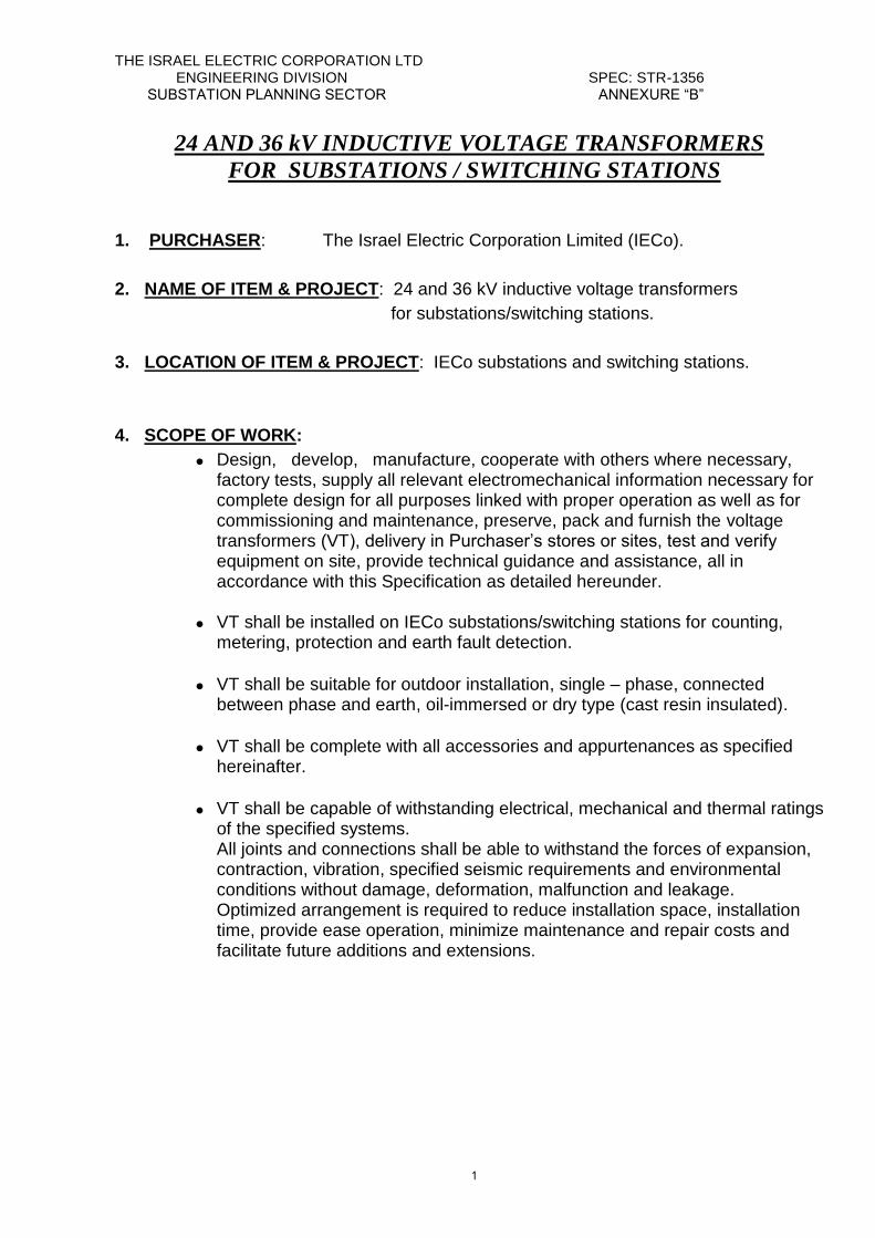
THE ISRAEL ELECTRIC CORPORATION LTD ENGINEERING DIVISION SPEC: STR-1356 SUBSTATION PLANNING SECTOR ANNEXURE “B”
1
24 AND 36 kV INDUCTIVE VOLTAGE TRANSFORMERS
FOR SUBSTATIONS / SWITCHING STATIONS
1. PURCHASER: The Israel Electric Corporation Limited (IECo).
2. NAME OF ITEM & PROJECT: 24 and 36 kV inductive voltage transformers
for substations/switching stations.
3. LOCATION OF ITEM & PROJECT: IECo substations and switching stations.
4. SCOPE OF WORK:
3.1
Design, develop, manufacture, cooperate with others where necessary, factory tests, supply all relevant electromechanical information necessary for complete design for all purposes linked with proper operation as well as for commissioning and maintenance, preserve, pack and furnish the voltage transformers (VT), delivery in Purchaser’s stores or sites, test and verify equipment on site, provide technical guidance and assistance, all in accordance with this Specification as detailed hereunder.
3.2
VT shall be installed on IECo substations/switching stations for counting, metering, protection and earth fault detection.
3.3
VT shall be suitable for outdoor installation, single – phase, connected between phase and earth, oil-immersed or dry type (cast resin insulated).
3.4
VT shall be complete with all accessories and appurtenances as specified hereinafter.
3.5
VT shall be capable of withstanding electrical, mechanical and thermal ratings of the specified systems. All joints and connections shall be able to withstand the forces of expansion, contraction, vibration, specified seismic requirements and environmental conditions without damage, deformation, malfunction and leakage. Optimized arrangement is required to reduce installation space, installation time, provide ease operation, minimize maintenance and repair costs and facilitate future additions and extensions.
THE ISRAEL ELECTRIC CORPORATION LTD ENGINEERING DIVISION SPEC: STR-1356 SUBSTATION PLANNING SECTOR ANNEXURE “B”
2
4.1. SCOPE OF SUPPLY / SERVICE:
The Contractor shall supply the following items:
4.1.1 Item 1: 24 kV inductive voltage transformer, ratio 24/√3 // 0.11/√3 // 0.11/3 kV, and two secondary windings with accuracy class 0.5 for one winding and 3P for the second winding, complete with base and all accessories and appurtenances for outdoor installation. Quantity: 36 units + 50% − 20%.
4.1.2 Item 2: 36 kV inductive voltage transformer, ratio 36/√3 // 0.11/√3 // 0.11/3 kV, and two secondary windings with accuracy class 0.5 for one winding and 3P for the second winding, complete with base and all accessories and appurtenances for outdoor installation. Quantity: 84 units + 50% − 20%.
4.1.3 4.1.4
Item 3: Spare parts – Option. Item 4: Special tools – Option.
4.1.5 4.1.6
The quantities indicated above are not final. The IECo reserves the right to purchase, during the Contract period, goods of a total value, which equals to Contract value with deviation of plus 50% minus 20% with possibility to alternate between items and quantities. In addition to a/m items, the Contractor shall submit with the technical proposal 1 (one) unit of each proposed type of the voltage transformer (items 1 and 2) for carrying out the sample tests in the Purchaser's laboratory ©.
4.1.7 In addition to the equipment the Contractor shall provide all technical data,
relevant drawings and other information as required in this Specification.
5. TERMINAL POINTS & TERMINAL CONNECTION 5.1 The Contractor is requested to propose the VT as a whole.
In case the Contractor has not in his production line one or more of the required components, he can offer components manufactured by other manufacturers. The Contractor shall be responsible for the integration of all components and will guarantee for the whole VT. The list of subcontractors shall be approved by Purchaser.
5.2 The Contractor shall use components and accessories manufactured in
Israel wherever possible. 5.3 The Contractor shall be responsible for all equipment damage until time of
Purchaser equipment reception.
THE ISRAEL ELECTRIC CORPORATION LTD ENGINEERING DIVISION SPEC: STR-1356 SUBSTATION PLANNING SECTOR ANNEXURE “B”
3
5.4 The VT can be supplied only after approval of all type, special and routine
test reports.
6. QUALITY ASSURANCE & QUALITY CONTROL
6.1 General quality requirements
6.1.1 In addition to the provisions of the General Conditions Annexure "A" -"Contractor's Documentation" and Appendix N° 2 - "Procurement Quality Requirements" the Contractor's Quality Assurance Program shall meet the requirements described in ISO Standard 9001-2000.
6.1.2 The Purchaser shall have the right to audit and comment on Contractor's
Quality Assurance System regardless of whether it was previously audited by certifying agency or any other body.
6.1.3 The Contractor shall be responsible for assuring that his subcontractor's
Quality Assurance/Quality Control Program, including their organizations, procedures, personnel qualification etc., are approved and are consistent with the specific requirements imposed by Purchaser in the Specification.
6.1.4 An Inspection &Test Plan, including witness points and hold points, shall be
mutually agreed between the Purchaser and the Contractor immediately after awarding the contract. Any subsequent alteration to this program shall require the Purchaser's agreement, prior to start of any work affected by these alterations.
6.1.5 When subcontracting part of the works, the Contractor shall submit copies of his unpriced orders to the subcontractor.
6.1.6 Test and inspection certificates as required in the Specification and the
applicable standards, shall be submitted immediately following their issue. The certificates have to be original, signed by the Contractor, and contain actual measured values. The generation of certificates, including those generated by Subcontractors and sub-Bidders, shall bear no extra cost to Purchaser.
6.1.7 Manufacturing shall not commence prior to respective drawing approval by the
Purchaser.
6.1.8 Changes in the Purchaser's approved design are normally unaccepted. However, should such changes become necessary on an exceptional basis, the Contractor shall obtain the Purchaser's approval prior to introducing any change.
6.1.9 Any equipment which does not conform to drawings, specifications or other
purchase order requirements which never the less are considered by the Contractor as "acceptable as is" or "for repair", shall be submitted to the Purchaser for approval, with their recommended dispositions. All such non-
THE ISRAEL ELECTRIC CORPORATION LTD ENGINEERING DIVISION SPEC: STR-1356 SUBSTATION PLANNING SECTOR ANNEXURE “B”
4
conformances shall be approved by the Purchaser, shall be documented and a copy of the approval shall accompany each shipment.
6.1.10 Source inspection, including inspection of local manufacturing, shall be
conducted by proficient, approved organizations or individuals, using documented procedures. Any such independent inspector shall be subject to Purchaser's approval.
6.1.11 All materials used in the manufacture of the equipment shall conform to the
Specification, approved drawings and accepted standards.
6.1.12 The Contractor shall notify the Purchaser, without any undue delay, of any defect, failure, malfunction or incompatibility in the equipment, or in similar types of equipment, which shall have appeared, or discovered in the course of the period, extending from the execution of the contract of supply until three years after the expiration of warranty, in as much as it affects, or may affect the use, performance, qualities, lifetime or safety of the equipment. The notification shall be in writing and shall specify the nature of the defect, failure, malfunction or incompatibility, any ramifications, stemming therefrom and any relevant corrective measures, adopted or recommended by the Manufacturer.
6.1.13 The Purchaser shall have the right to be present in the equipment
manufacturing process (at least two times during the manufacturing), as far as in the routing and acceptance tests performance.
6.2 Interchangeability
Voltage Transformers of the same type and ratings shall be interchangeable both electrically and mechanically with each other, and when so interchanged shall perform their function equally well in every respect.
7 STANDARDS & CODES
Unless otherwise specified all equipment shall be designed, manufactured and
tested in accordance with the requirements of the latest relevant published standards of the International Electrotechnical Commission (IEC) or local standards of the Manufacturer's country as amended up to date.
All aspects, test, etc, not covered by the above mentioned standards, shall be executed according to the latest published issue of official or otherwise approved standards of the Manufacturer's country.
All relevant standards shall be stated by Bidder. In the event of a variance between the general requirements of the standards and particular requirements of this Specification, the Specification shall take precedence.
THE ISRAEL ELECTRIC CORPORATION LTD ENGINEERING DIVISION SPEC: STR-1356 SUBSTATION PLANNING SECTOR ANNEXURE “B”
5
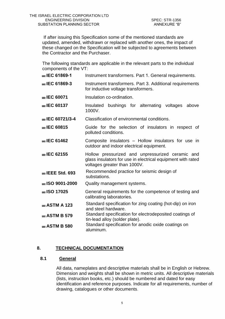
If after issuing this Specification some of the mentioned standards are updated, amended, withdrawn or replaced with another ones, the impact of these changed on the Specification will be subjected to agreements between the Contractor and the Purchaser. The following standards are applicable in the relevant parts to the individual components of the VT:
IEC 69681-9 Instrument transformers. Part 1. General requirements.
IEC 69681-3 Instrument transformers. Part 3. Additional requirements
for inductive voltage transformers.
IEC 60071 Insulation co-ordination.
IEC 60137 Insulated bushings for alternating voltages above
1000V.
IEC 60721/3-4 Classification of environmental conditions.
IEC 60815 Guide for the selection of insulators in respect of
polluted conditions.
IEC 61462 Composite insulators – Hollow insulators for use in
outdoor and indoor electrical equipment.
IEC 62155 Hollow pressurized and unpressurized ceramic and
glass insulators for use in electrical equipment with rated voltages greater than 1000V.
IEEE Std. 693 Recommended practice for seismic design of
substations. ISO 9001-2000 Quality management systems.
ISO 17025 General requirements for the competence of testing and
calibrating laboratories.
ASTM A 123 Standard specification for zing coating (hot-dip) on iron
and steel hardware. ASTM B 579 Standard specification for electrodeposited coatings of
tin-lead alloy (solder plate). ASTM B 580 Standard specification for anodic oxide coatings on
aluminum.
8. TECHNICAL DOCUMENTATION
8.1 General
All data, nameplates and descriptive materials shall be in English or Hebrew. Dimension and weights shall be shown in metric units. All descriptive materials (lists, instruction books, etc.) should be numbered and dated for easy identification and reference purposes. Indicate for all requirements, number of drawing, catalogues or other documents.
THE ISRAEL ELECTRIC CORPORATION LTD ENGINEERING DIVISION SPEC: STR-1356 SUBSTATION PLANNING SECTOR ANNEXURE “B”
6
During the tender process, IECo, on its own discretion, may ask to receive additional technical documents relevant to the bidder’s proposal. The bidder will be obliged to submit the documents according to a specified time.
8.2 Technical documents to accompany the proposal
The Contractor should submit with the proposal the following documents and information in four (4) copies, and four (4) compact discs in word format (dwg. format for drawings):
8.2.1. Summary of Data: All Clauses.
8.2.2. Quality Assurance documentation Quality Assurance related documentation, according to the Appendix No.2: "PROCUREMENT QUALITY REQUIREMENTS" (spec. No: Q – APP – 02) should be submitted for information. Particularly the following:
Certification of Approval of the Quality Assurance System according to the ISO 9001 Standard given by an Authorized Inspection Agency.
A list of Quality Assurance Standards and Quality Assurance Manual.
Design control procedures.
Quality plan during manufacture.
Acceptance test procedures for materials and sub-assembles.
Non-conformance and corrective action procedures.
Qualification of Subcontractor's Procedure.
List of qualified Bidders of the most important parts and components.
A preliminary Inspection and Test Plant (I&T plan).
8.2.3. Drawings and tests
Dimension drawings giving principal dimensions.
Description of the principles of operating of the VT under various operating conditions.
Description of pressure relief and sealing arrangement.
Drawing of cross section of the voltage transformer.
Description and drawing of insulator from Manufacturer.
Drawing of line and earth terminals.
Drawing of nameplate.
Drawing of pressure relief.
Drawing of the connection between the primary terminal and primary winding.
Manufacturer proposal for connection of the line terminal to the HV busbar.
Certificate for insulating oil (Appendix № 5, pages 8 to 10).
Construction, mode of operation, mounting, connection arrangement and checking of the VT.
Type and special tests reports (authority, number and date) for offered type of VT, including test circuit, instruments used and description of method, calibration certificate.
THE ISRAEL ELECTRIC CORPORATION LTD ENGINEERING DIVISION SPEC: STR-1356 SUBSTATION PLANNING SECTOR ANNEXURE “B”
7
Type and special tests reports (authority, number and date) for offered type of insulator, including test circuit, instruments used and description of method.
Example of routine test report for offered type of VT, including test circuit, instruments used and description of method.
Reliability, availability, maintainability and safety (RAMS) report (Appendix № 3).
Customer list for the last five years, with sum for each year (type, rated voltage, rated discharge current, number of units, date of supply, Purchaser).
A list of recommended special tools and instruments necessary for assembling of the VT.
A list of recommended spare parts (including total quantities) for the amount of VT indicated in this Specification.
A list of all parts which could wear out after expiration of the warranty period, after 5 years and 10 years of operating according to Manufacturer or users experience.
General instruction book for storage, erection, operating and maintaining.
Recommendations for transport on roads and on site.
Recommendations for prolonged (2-3 years) storage before erection, taking into consideration the specific conditions under clause 9.
Details of shock indicator.
8.2.4. A proposal not including the documents mentioned above can be rejected.
8.2.5. Contractor may be required to send his representative to discuss and/or explain parts of his proposal with IECo's representatives.
8.2.6. All the drawings and information submitted with the proposal shall be final
drawings and final information approved by the Bidder. 8.2.7. In addition to a/m technical documents, the Contractor shall submit
with the technical proposal 1 (one) unit of each proposed type of the voltage transformer (items 1 and 2) for carrying out the sample tests in the Purchaser's laboratory ©.
8.2.8. Evaluation of bidder's technical proposal All requirements in this Specification indicated by the symbol are
compulsory requirements. In case Bidder’s proposal will not comply with one of the compulsory requirements, his offer will be disqualified.
For evaluation purposes the Bidder is requested to fill in, in the Summary of
Data, the offered data and parameters against Purchaser’s required values as well as in the absence thereof, in the free columns of the right hand side. A definite answer (yes or no) or appropriate comments shall be given to all other requirements.
THE ISRAEL ELECTRIC CORPORATION LTD ENGINEERING DIVISION SPEC: STR-1356 SUBSTATION PLANNING SECTOR ANNEXURE “B”
8
8.3 Technical documents after notification of award
8.3.1. After notification of award, Contractor shall within 30 (thirty) days of the date of award, submit to the Purchaser for approval four (4) sets of prints and four (4) compact discs in word format (dwg. format for drawings) covering the following information:
Outline drawing of VT including all necessary details for mounting such as fixing holes, size and material of primary and earthing terminals, weight, permissible static and dynamic forces.
Sectional view through the complete VT showing the arrangement and details of pressure relief device, method of sealing and prevention of internal condensation etc. as well as materials used.
Line and earth terminals details (material, shape, cross-section).
Description and Manufacturer's insulator drawing.
Schematic and detailed wiring drawings.
Technical catalogs of VT.
Nameplate drawing with all data fulfilled.
Bill of materials.
Shipping assembly drawing with overall size and weight.
Final list of all subcontractors and sub suppliers including name, address and a copy of their Quality Assurance Certificate.
8.3.2. After notification of award, Contractor shall within 60 (sixty)days of date of award, submit to the Purchaser four (4) sets of prints of Quality Assurance Manual including a full description of Contractor's Quality Assurance
program.
Contractor shall furnish the following Quality Control documentation:
Inspection and Test Plan included in Contractor's Quality plan.
Quality Control Procedures.
Testing procedures as per applicable standards.
Non-conformance's procedures.
List of sub-suppliers of the most important parts and components.
8.3.3. Purchaser reserves himself the right to require all necessary additional data, descriptions, drawings, etc. that may contribute in completing information supplied by Manufacturer about the equipment.
8.3.4. If the prints are returned by the Purchaser and stamped "approved except as noted", Contractor shall make corrections per Purchaser's marking and shall resubmit required copies of the correct documents as stated above.
8.3.5. Routine test reports shall be submitted for approval 1 (one) month before delivery, in four (4) copies.
8.3.6. The shipment cannot be realized before test approval. 8.3.7. Commissioning program shall be supplied for approval in four (4) copies,
three (3) months before delivery.
THE ISRAEL ELECTRIC CORPORATION LTD ENGINEERING DIVISION SPEC: STR-1356 SUBSTATION PLANNING SECTOR ANNEXURE “B”
9
8.3.8. Contractor is free to supply any additional information considered necessary for clarifying various aspects of erection, operation, maintaining, checking, etc.
8.3.9. All documents and drawings shall be provide with:
Purchaser name.
Project name.
Unit serial number.
Purchaser's order number.
Specification number.
Supplier's order number.
9. TECHNICAL REQUIREMENTS
9.1. Environmental considerations & service conditions
9.1.1. Climatic conditions
Long periods without rain, alternating with high humidity as experienced in coastal or desert areas in this country.
Permissible ambient air temperature:
Maximum: +50 °C. Minimum: -5 °C. Average value over a period of 24 hours not exceeds: +35 °C.
Permissible humidity: Low relative/absolute humidity: 4/0.003 %//g/ m³. High relative/absolute humidity: 100/36 %//g/ m³.
Low/high air pressure: 70/106 KPa.
Rain intensity: 15 mm/min.
Keraunic level (thunderstorm): Maximum keraunic level: 4 lightning / km² year Minimum keraunic level: 0.1 lightning / km² year
Direct and continuous solar radiation for long period. Heating effects of solar radiation: 1000 W/m².
Maximum wind velocity measured 10 m above ground (bare area) at 3 sec duration considering a 50 years mean return period: 88 m/sec.
9.1.2. Environmental conditions
Environmental parameters according to IEC 60721, 3-4.
Severe atmospheric and industrial air pollution, dust, salt spray and sandstorms.
Permissible altitude over the sea level: 1000 m.
Water from sources other than rain: spraying water and water jets with water velocity 15 m/sec.
THE ISRAEL ELECTRIC CORPORATION LTD ENGINEERING DIVISION SPEC: STR-1356 SUBSTATION PLANNING SECTOR ANNEXURE “B”
11
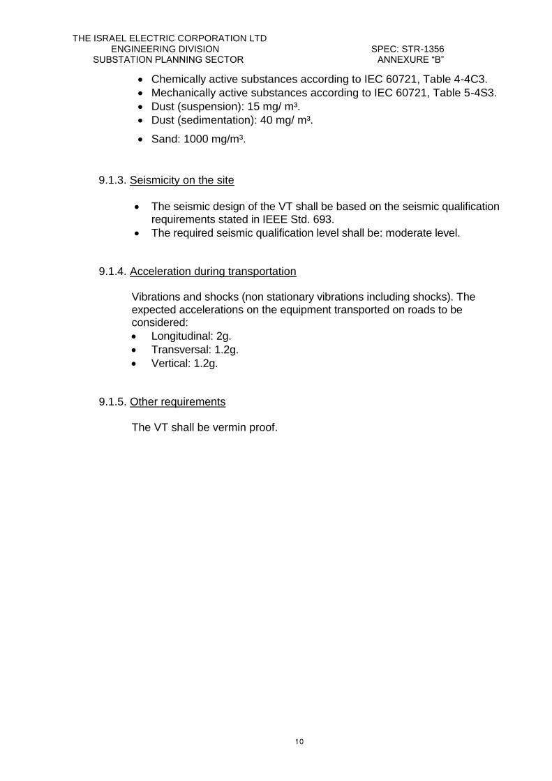
Chemically active substances according to IEC 60721, Table 4-4C3.
Mechanically active substances according to IEC 60721, Table 5-4S3.
Dust (suspension): 15 mg/ m³.
Dust (sedimentation): 40 mg/ m³.
Sand: 1000 mg/m³.
9.1.3. Seismicity on the site
The seismic design of the VT shall be based on the seismic qualification requirements stated in IEEE Std. 693.
The required seismic qualification level shall be: moderate level.
9.1.4. Acceleration during transportation Vibrations and shocks (non stationary vibrations including shocks). The expected accelerations on the equipment transported on roads to be considered:
Longitudinal: 2g.
Transversal: 1.2g.
Vertical: 1.2g.
9.1.5. Other requirements
The VT shall be vermin proof.
THE ISRAEL ELECTRIC CORPORATION LTD ENGINEERING DIVISION SPEC: STR-1356 SUBSTATION PLANNING SECTOR ANNEXURE “B”
11
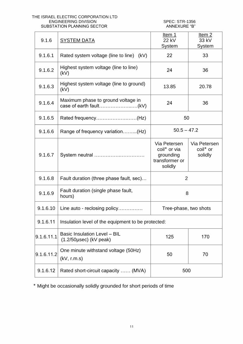
9.1.6 SYSTEM DATA 1Item
22 kV System
Item 2 33 kV
System
9.1.6.1 Rated system voltage (line to line) (kV) 22 33
9.1.6.2 Highest system voltage (line to line) (kV)
28 36
9.1.6.3 Highest system voltage (line to ground) (kV)
13.85 20.78
9.1.6.4 Maximum phase to ground voltage in case of earth fault………………...…(kV)
28 36
9.1.6.5 Rated frequency……………….……(Hz) 55
9.1.6.6 Range of frequency variation……...(Hz) 50.5 – 47.2
9.1.6.7 System neutral …………….……………
Via Petersen coil٭ or via grounding
transformer or solidly
Via Petersen coil٭ or solidly
9.1.6.8 Fault duration (three phase fault, sec)… 2
9.1.6.9 Fault duration (single phase fault, hours)
8
9.1.6.10 Line auto - reclosing policy…………… Tree-phase, two shots
9.1.6.11 Insulation level of the equipment to be protected:
9.1.6.11.1 Basic Insulation Level – BIL (1.2/50µsec) (kV peak)
125 175
9.1.6.11.2 One minute withstand voltage (50Hz)
(kV, r.m.s) 55 75
9.1.6.12 Rated short-circuit capacity …… (MVA) 555
Might be occasionally solidly grounded for short periods of time ٭
THE ISRAEL ELECTRIC CORPORATION LTD ENGINEERING DIVISION SPEC: STR-1356 SUBSTATION PLANNING SECTOR ANNEXURE “B”
12
9.1.7 Special requirements for environmental protection 9.1.7
.1 Due to the severe environmental conditions to which the equipment may be subjected during its service life, the following requirements for its protection form an integral part of the Specification and are in addition to the standard design and protective measures which the Manufacturer would normally invoke for these conditions:
9.1.7
.2 All aluminum components shall be fabricated from grades of aluminum which show resistance to salt spray and moist conditions; e.g., Al-Mg base alloys. Al-Cu alloys are not acceptable. After fabrication, all aluminum components shall be anodized according to ASTM B 580 Type A.
9.1.7
.3 All copper or copper alloy components shall be electrolytically tinned according to ASTM B 579 Service Condition SC4.
9.1.7
.4 Bolts, nuts and washers as well as components such as springs, pins and
those for which a tight maintained dimensional tolerance is required shall be
made of stainless steel. The preferred stainless steel is an austenitic grade;
however, if physical requirements are overriding, other stainless steel grades
will be acceptable.
Austenitic grade will be subject to a solution quench. Prior to being placed into service all stainless steel components will be cleaned and passivated.
9.1.7
.5 When dimensionally and functionally allowable, all structural support and
associated steelwork of the equipment shall be hot-dip galvanized according
to ASTM A 123. The thickness of the zinc shall be at least 100µm on
average, but the minimum thickness shall be not less than 90µm.
If dimensional or functional requirements do not allow hot-dip galvanizing,
steel parts will be electrolytically zinc plated to a minimum measured
thickness of 20µm.
9.1.7.6
Components such as sleeves or bushings which may be fabricated having
an inner face of one metal and a supporting outer face of another, or
conductors which are used with connectors of a dissimilar metal, are to have
their exposed interfaces protected against moisture.
9.1.7.7
All exposed metal surfaces of the VT shall be coated according to
Manufacturer's standard. Include in your technical proposal the painting
standard you will use.
9.1.7
.8 All components shall successfully withstand in operation the climatic and environmental conditions as defined under clause 9.1.
THE ISRAEL ELECTRIC CORPORATION LTD ENGINEERING DIVISION SPEC: STR-1356 SUBSTATION PLANNING SECTOR ANNEXURE “B”
13
9.1.7.9
Manufacturer is requested to describe or indicate deviations (see clause 15.2, Annexure "B") from above requirements. In case no deviations are mentioned it will be understood that Manufacturer's offer entirely complies with the above-mentioned requirements.
9.2. Reliability, availability, maintainability (RAM) The Bidder is requested to fill in the enclosed Appendix № 3 “Reliability,
availability, maintainability and safety” based on relevant information from
users. Bidder shall describe the system of relevant data collection from users.
This data is to establish the Contractor’s reliability statements.
9.3. Functional requirements Not relevant.
9.4. Properties
RATINGS
9.4.1 Rated primary voltage: IEC 61869
9.4.1.1 Item 1 (kV) …………………………………… 24/√3 © 9.4.1.2 Item 2 (kV) …………………………………… 36/√3 ©
9.4.2 Rated secondary voltage:
9.4.2.1 Secondary winding № 1 (V) ………………. 110/√3 © 9.4.2.2 Secondary winding № 2 (V) …………….... 110/3 ©
9.4.3 Secondary windings and destination:
9.4.3.1 Secondary winding № 1 …………………... Counting and measuring
9.4.3.2 Secondary winding № 2 …………………... Protection
9.4.4 Accuracy class of secondary windings:
9.4.4.1 Secondary winding № 1 …………………... 0.5 9.4.4.2 Secondary winding № 2 …………………... 3P
9.4.5 Rated output at a power factor of 0.8 lagging: 9.4.5.1 Secondary winding № 1 (VA) ……………. 100 9.4.5.2 Secondary winding № 2 (VA) …………….. 100 9.4.5.3 Total simultaneous load in specified accuracy
class (VA) ................................................. 255
9.4.6 Rated frequency (Hz)……………………… 50 ©
THE ISRAEL ELECTRIC CORPORATION LTD ENGINEERING DIVISION SPEC: STR-1356 SUBSTATION PLANNING SECTOR ANNEXURE “B”
14
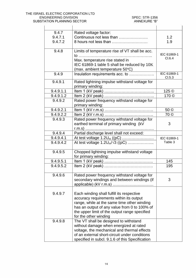
9.4.7 Rated voltage factor:
9.4.7.1 Continuous not less than …………………. 1.2 9.4.7.2 8 hours not less than ……………………… 1.9
9.4.8 Limits of temperature rise of VT shall be acc. to ……………………………………………….. Max. temperature rise stated in
IEC 61869-1 table 5 shall be reduced by 10K (max. ambient temperature 50ºC)
IEC 61869-1
Cl.6.4
9.4.9 Insulation requirements acc. to ………………. IEC 61869-1 Cl.5.3
9.4.9.1 Rated lightning impulse withstand voltage for primary winding:
9.4.9.1.1 Item 1 (kV peak) ……………………………….. 125 ©
9.4.9.1.2 Item 2 (kV peak) ……………………………….. 170 ©
9.4.9.2 Rated power frequency withstand voltage for primary winding:
9.4.9.2.1 Item 1 (kV r.m.s) ………………………………. 50 ©
9.4.9.2.2 Item 2 (kV r.m.s) ………………………………. 70 ©
9.4.9.3 Rated power frequency withstand voltage for earthed terminal of primary winding (kV r.m.s) …………………………………………….
3
9.4.9.4 Partial discharge level shall not exceed:
9.4.9.4.1 At test voltage 1.2Um ((pC) …………………… IEC 61869-1 Table 3 9.4.9.4.2 At test voltage 1.2Um/√3 ((pC) ………………..
9.4.9.5 Chopped lightning impulse withstand voltage for primary winding:
9.4.9.5.1 Item 1 (kV peak) ………………………………. 145
9.4.9.5.2 Item 2 (kV peak) ………………………………. 195
9.4.9.6 Rated power frequency withstand voltage for secondary windings and between windings (if applicable) (kV r.m.s) ………………………….
3
9.4.9.7 Each winding shall fulfill its respective
accuracy requirements within its output range, while at the same time other winding has an output of any value from 0 to 100% of the upper limit of the output range specified for the other winding
9.4.9.8 The VT shall be designed to withstand without damage when energized at rated voltage, the mechanical and thermal effects of an external short-circuit under conditions specified in subcl. 9.1.6 of this Specification
THE ISRAEL ELECTRIC CORPORATION LTD ENGINEERING DIVISION SPEC: STR-1356 SUBSTATION PLANNING SECTOR ANNEXURE “B”
15
9.5. Design & construction
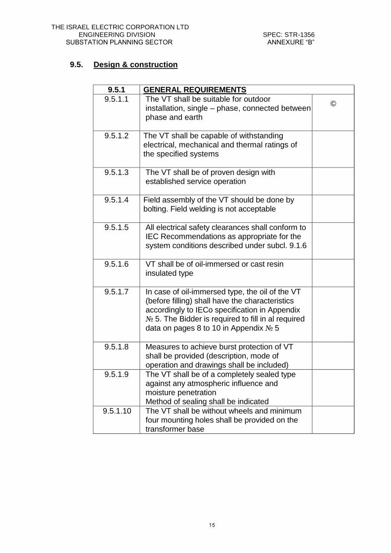
9.5.1 GENERAL REQUIREMENTS
9.5.1.1 The VT shall be suitable for outdoor installation, single – phase, connected between phase and earth
©
9.5.1.2 The VT shall be capable of withstanding electrical, mechanical and thermal ratings of the specified systems
9.5.1.3 The VT shall be of proven design with established service operation
9.5.1.4 Field assembly of the VT should be done by bolting. Field welding is not acceptable
9.5.1.5 All electrical safety clearances shall conform to IEC Recommendations as appropriate for the system conditions described under subcl. 9.1.6
9.5.1.6 VT shall be of oil-immersed or cast resin insulated type
9.5.1.7 In case of oil-immersed type, the oil of the VT (before filling) shall have the characteristics accordingly to IECo specification in Appendix № 5. The Bidder is required to fill in al required data on pages 8 to 10 in Appendix № 5
9.5.1.8 Measures to achieve burst protection of VT shall be provided (description, mode of operation and drawings shall be included)
9.5.1.9 The VT shall be of a completely sealed type against any atmospheric influence and moisture penetration Method of sealing shall be indicated
9.5.1.10 The VT shall be without wheels and minimum four mounting holes shall be provided on the transformer base
THE ISRAEL ELECTRIC CORPORATION LTD ENGINEERING DIVISION SPEC: STR-1356 SUBSTATION PLANNING SECTOR ANNEXURE “B”
16
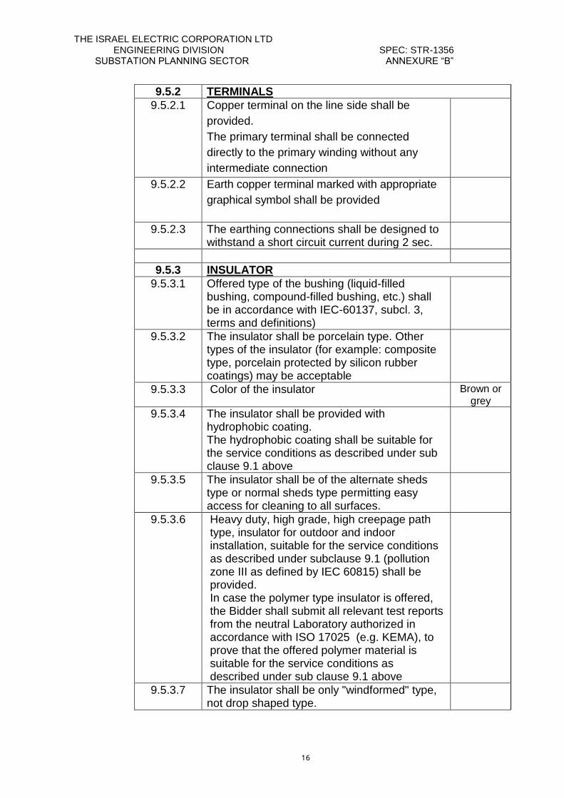
9.5.2 TERMINALS
9.5.2.1 Copper terminal on the line side shall be
provided.
The primary terminal shall be connected
directly to the primary winding without any
intermediate connection
9.5.2.2 Earth copper terminal marked with appropriate
graphical symbol shall be provided
9.5.2.3 The earthing connections shall be designed to withstand a short circuit current during 2 sec.
9.5.3 INSULATOR
9.5.3.1 Offered type of the bushing (liquid-filled bushing, compound-filled bushing, etc.) shall be in accordance with IEC-60137, subcl. 3, terms and definitions)
9.5.3.2 The insulator shall be porcelain type. Other types of the insulator (for example: composite type, porcelain protected by silicon rubber coatings) may be acceptable
9.5.3.3 Color of the insulator Brown or grey
9.5.3.4 The insulator shall be provided with hydrophobic coating. The hydrophobic coating shall be suitable for the service conditions as described under sub clause 9.1 above
9.5.3.5 The insulator shall be of the alternate sheds type or normal sheds type permitting easy access for cleaning to all surfaces.
9.5.3.6 Heavy duty, high grade, high creepage path type, insulator for outdoor and indoor installation, suitable for the service conditions as described under subclause 9.1 (pollution zone III as defined by IEC 60815) shall be provided. In case the polymer type insulator is offered, the Bidder shall submit all relevant test reports from the neutral Laboratory authorized in accordance with ISO 17025 (e.g. KEMA), to prove that the offered polymer material is suitable for the service conditions as described under sub clause 9.1 above
9.5.3.7 The insulator shall be only "windformed" type, not drop shaped type.
THE ISRAEL ELECTRIC CORPORATION LTD ENGINEERING DIVISION SPEC: STR-1356 SUBSTATION PLANNING SECTOR ANNEXURE “B”
17
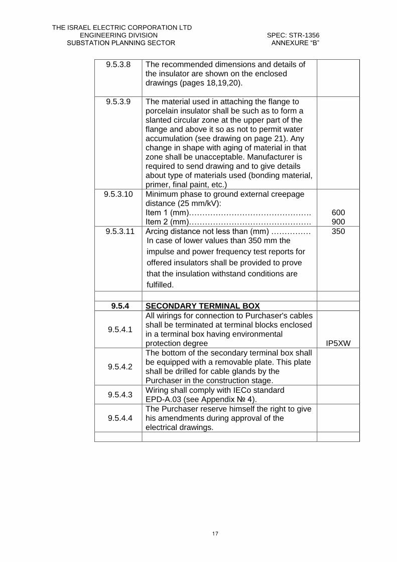
9.5.3.8 The recommended dimensions and details of the insulator are shown on the enclosed drawings (pages 18,19,20).
9.5.3.9 The material used in attaching the flange to porcelain insulator shall be such as to form a slanted circular zone at the upper part of the flange and above it so as not to permit water accumulation (see drawing on page 21). Any change in shape with aging of material in that zone shall be unacceptable. Manufacturer is required to send drawing and to give details about type of materials used (bonding material, primer, final paint, etc.)
9.5.3.10 Minimum phase to ground external creepage distance (25 mm/kV): Item 1 (mm)………………………………………. Item 2 (mm)……………………………………….
600 900
9.5.3.11 Arcing distance not less than (mm) …………… In case of lower values than 350 mm the
impulse and power frequency test reports for
offered insulators shall be provided to prove
that the insulation withstand conditions are
fulfilled.
350
9.5.4 SECONDARY TERMINAL BOX
9.5.4.1
All wirings for connection to Purchaser's cables shall be terminated at terminal blocks enclosed in a terminal box having environmental protection degree
IP5XW
9.5.4.2
The bottom of the secondary terminal box shall be equipped with a removable plate. This plate shall be drilled for cable glands by the Purchaser in the construction stage.
9.5.4.3 Wiring shall comply with IECo standard EPD-A.03 (see Appendix № 4).
9.5.4.4 The Purchaser reserve himself the right to give his amendments during approval of the electrical drawings.
THE ISRAEL ELECTRIC CORPORATION LTD ENGINEERING DIVISION SPEC: STR-1356 SUBSTATION PLANNING SECTOR ANNEXURE “B”
18
ALTERNATE-SHEDS TYPE INSULATOR
RECOMMENDED FOR ITEMS 1,2
S-S1 > S1
P1-P2 ≥ 15 mm
S1/P1 ≥ 0.8
C = mm
a > 5°
P.F. > 0.7
Kd = 1
Dm < 300 mm
l = 25 mm/kV
L ITEM1 = 600 mm
L ITEM2 = 900 mm
C.F. (L/A) ≤ 4
ld1/ d1
ld2/ d2
Kd = Factor to increase the creepage distance
Dm = (De1+De2+2Di)/4
l = Minimum specific creepage distance per phase (related to highest system voltage phase to phase)
L = Phase to ground external creepage distance
A = Arcing distance.
P.F. = Profile factor (2P1+2P2+S)ld2
C.F. = Creepage factor (L/A)
THE ISRAEL ELECTRIC CORPORATION LTD ENGINEERING DIVISION SPEC: STR-1356 SUBSTATION PLANNING SECTOR ANNEXURE “B”
19
NORMAL-SHEDS TYPE INSULATOR
RECOMMENDED FOR ITEMS 1,2
S/P ≥ 0.8
C = mm
a > 5°
P.F > 0.7
Kd = 1
Dm < 300 mm
l = 25 mm/kV
L ITEM1 = 600 mm
L ITEM2 = 900 mm
C.F. (L/A) ≤ 4
ld/ d
Kd = Factor to increase the creepage distance
Dm = (De +Di)/2
l = Minimum specific creepage distance per phase (related to highest system voltage phase to phase)
L = Phase to ground external creepage distance
A = Arcing distance.
P.F. = Profile factor (2P+S)ld
C.F. = Creepage factor (L/A)
THE ISRAEL ELECTRIC CORPORATION LTD ENGINEERING DIVISION SPEC: STR-1356 SUBSTATION PLANNING SECTOR ANNEXURE “B”
21
COMPOSITE INSULATOR
RECOMMENDED FOR ITEMS 1,2
S/P > 0.75 – 0.8
C = mm
a 12°
Kd = 1
Dm < 300 mm
l = 25 mm/kV
L ITEM 1 = 600 mm
L ITEM 2 = 900 mm
L/A < 4
ld/ d
Dti mm
Dte mm
Di mm
De mm
Kd = Factor to increase the creepage distance
Dm = (De +Di)/2; for 300mm < Dm < 500mm, kd=1.1
l = Minimum specific creepage distance per phase (related to highest system voltage phase to phase)
L = Phase to ground external creepage distance
A = Arcing distance
THE ISRAEL ELECTRIC CORPORATION LTD ENGINEERING DIVISION SPEC: STR-1356 SUBSTATION PLANNING SECTOR ANNEXURE “B”
21
No MATERIALS DETAILS
1. BONDING MATERIAL
2. PRIMER
3. FINAL PROTECTIVE PAINT
4. FLANGE MATERIAL
5. OTHER MATERIALS
THE ISRAEL ELECTRIC CORPORATION LTD ENGINEERING DIVISION SPEC: STR-1356 SUBSTATION PLANNING SECTOR ANNEXURE “B”
22
9.6. Commissioning
9.6.1 Contractor shall be responsible for the commissioning of all equipment covered under his contract in case it will be requested by Purchaser
9.6.2 Contractor shall prepare and submit three months prior to the start of commissioning, a Commissioning Program for approval by Purchaser
9.6.3 The Commissioning Program shall include indications for:
9.6.3.1 Commissioning inspection to detect faults which have occurred during transportation, storing or assembly at its final location
9.6.3.2 Preparation for use and procedures to describe the activities required to prepare systems for testing and operation
9.6.3.3 Checking of rated data, connection, loading etc. of the equipment and necessary interface with the equipment supplied by others
9.6.3.4 Testing as detailed in tests on site program including: - the test objective- test intent - required performance data- prerequisites - sequence of activities - acceptance criteria
9.6.3.5 Putting the equipment into service
9.6.3.6 Final check
9.6.3.7 The critical limits of each criteria for which the equipment should be drawn out from service
9.6.4 Changes and modifications to the Commissioning Program shall also be approved by Purchaser
9.6.5 Commissioning results shall be witnessed by the Purchaser and documented on forms to be agreed upon by the Contractor. The record shall include other such as omissions or unsatisfactory test results
9.6.6 The Contractor shall maintain an up to date record of all inspections and tests, which shall be handed over to Purchaser at the completion of the site testing and commissioning
9.6.7 The Purchaser shall be responsible for connection and disconnection of the equipment to and from system, including first energization, but with the advice and technical assistance of the Contractor (if required)
THE ISRAEL ELECTRIC CORPORATION LTD ENGINEERING DIVISION SPEC: STR-1356 SUBSTATION PLANNING SECTOR ANNEXURE “B”
23
9.6.8 The Contractor shall be responsible for supplying commissioning personnel with a good knowledge in all relevant operations prior and for commissioning and will be requested to submit a list giving name, experience and proposed duration on site
9.6.9 The Contractor shall be responsible for safety of personnel, ours or his own, involved in commissioning and shall take all possible precautions and be fully aware of dangers involved in testing. Contractor's personnel should also be ensured against death, personal accident and health while in Israel and be covered by Employers Liability Insurance applicable in their country of origin
9.6.10 Major failure or damage to equipment will require either its return to the factory or assignment of a special crew to carry out repairs
9.6.11 Commissioning personnel shall repair minor failure
9.6.12 All expensive (including transport to factory and return) in connection with damages and repairs as described above shall be paid by Contractor
9.6.13 If supervision of erection or commissioning by Contractor is necessary it have to be indicated
9.6.14 The validity of the warranty period shall be confirmed also in case that the erection and commissioning will be performed by Purchaser without Contractor supervision
9.7. Operation & maintenance
9.7.1. General
9.7.1.1. The VT shall be designed for live-washing (automatic and manual) taking into account service conditions described under subcl.9.1.
9.7.1.2. A complete set of tools for maintenance and repair work (if applicable) shall be
provided together with relevant drawings or photos and full instructions for use in English.
THE ISRAEL ELECTRIC CORPORATION LTD ENGINEERING DIVISION SPEC: STR-1356 SUBSTATION PLANNING SECTOR ANNEXURE “B”
24
9.7.1.3. Manufacturer shall ensure spare parts (if applicable) for the delivered
equipment for a period of life duration. 9.7.1.4. Manufacture shall ensure training course for IEC erection and operating
people. 9.7.2. Spare & renewal parts 9.7.2.1. The Contractor shall indicate in the Proposal the life duration of the VT and
the normal replacement cycle. 9.7.2.2. The Contractor shall include in its technical proposal a detailed list of
spare parts, recommended for:
- The short term: start-up, commissioning and until expiration of the
warranty period.
- The long term: spare parts for periods of 5 (five) and 10 (ten) years
after the end of the warranty period.
9.7.2.3. The catalog and the lists shall include for each item:
- Item description and item designation.
- Likelihood that the part will be required for replacement during each
relevant period (short term, long term).
- Name of Contractor and Manufacturer.
- Necessary catalogue data for separate order.
- Optimal stocking level.
- If the supply is from the stock or by manufacturing after order.
- Lead time before supply (including transport time to Israel).
- Price.
9.7.2.4. All Spare Parts shall be new and unused in all cases.
The Purchaser reserves the right to purchase said parts directly from
the Manufacturer or from another subcontractor.
The Contractor warrants that spare and renewal parts shall be
available for at least ten (10) years after supplying of the VT.
The Contractor guarantees that all the Spare Parts features will be
according to its catalogue and that the catalogue is periodically
updated.
The Contractor shall give tree lists of recommended spare parts.
THE ISRAEL ELECTRIC CORPORATION LTD ENGINEERING DIVISION SPEC: STR-1356 SUBSTATION PLANNING SECTOR ANNEXURE “B”
25
10. TESTS & INSPECTIONS
10.1 TESTS - GENERAL
10.1.1 Contractor shall perform Production Tests to check the quality and uniformity of the workmanship and materials used in the manufacture of the VT
10.1.2 Tests shall be carried out according to requirements further specified and 4 (four) copies of the relevant test reports for the proposed type of equipment shall be submitted to Purchaser with the proposal
10.1.3 8 (eight) weeks prior to the execution of the routine tests (also special tests) the Contractor shall notify the Purchaser of the exact date of performing the test
10.1.4 The Contractor shall submit test data to prove that the design has the capability to meet all the ratings as specified in Annexure "B" as well as relevant test reports
10.1.5 The Contractor shall prepare and submit an acceptance test plan according to this Specification at least 8 (eight) weeks before the testing
10.1.6 The Purchaser can require to carry out the tests in the presence of the Purchaser representatives
10.1.7 The Contractor shall submit a list of all tests to be performed on site, after mounting of the equipment and during operation
10.1.8 The Contractor shall indicate permissible tolerance for each
test value
10.1.9 Contractor shall submit with the test reports a list of all measuring instruments including their accuracy class and type, test equipment and test circuits, calibration certificate from authorized laboratory
10.1.10 The equipment can be delivered only after Purchaser's approval of all relevant routine test reports
THE ISRAEL ELECTRIC CORPORATION LTD ENGINEERING DIVISION SPEC: STR-1356 SUBSTATION PLANNING SECTOR ANNEXURE “B”
26
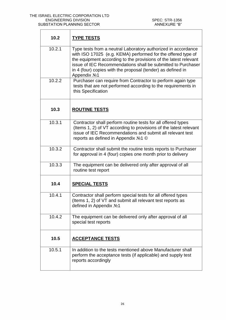
10.2 TYPE TESTS
10.2.1 Type tests from a neutral Laboratory authorized in accordance with ISO 17025 (e.g. KEMA) performed for the offered type of the equipment according to the provisions of the latest relevant issue of IEC Recommendations shall be submitted to Purchaser in 4 (four) copies with the proposal (tender) as defined in Appendix №1
10.2.2 Purchaser can require from Contractor to perform again type tests that are not performed according to the requirements in this Specification
10.3 ROUTINE TESTS
10.3.1 Contractor shall perform routine tests for all offered types (Items 1, 2) of VT according to provisions of the latest relevant issue of IEC Recommendations and submit all relevant test reports as defined in Appendix №1 ©
10.3.2 Contractor shall submit the routine tests reports to Purchaser for approval in 4 (four) copies one month prior to delivery
10.3.3 The equipment can be delivered only after approval of all routine test report
10.4 SPECIAL TESTS
10.4.1 Contractor shall perform special tests for all offered types (Items 1, 2) of VT and submit all relevant test reports as defined in Appendix №1
10.4.2 The equipment can be delivered only after approval of all special test reports
10.5 ACCEPTANCE TESTS
10.5.1 In addition to the tests mentioned above Manufacturer shall perform the acceptance tests (if applicable) and supply test reports accordingly
THE ISRAEL ELECTRIC CORPORATION LTD ENGINEERING DIVISION SPEC: STR-1356 SUBSTATION PLANNING SECTOR ANNEXURE “B”
27
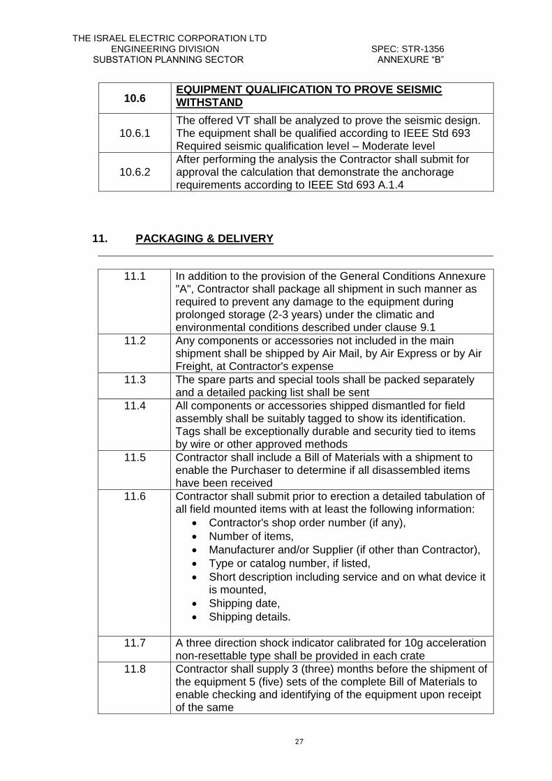
10.6 EQUIPMENT QUALIFICATION TO PROVE SEISMIC WITHSTAND
10.6.1 The offered VT shall be analyzed to prove the seismic design. The equipment shall be qualified according to IEEE Std 693 Required seismic qualification level – Moderate level
10.6.2 After performing the analysis the Contractor shall submit for approval the calculation that demonstrate the anchorage requirements according to IEEE Std 693 A.1.4
11. PACKAGING & DELIVERY
11.1 In addition to the provision of the General Conditions Annexure "A", Contractor shall package all shipment in such manner as required to prevent any damage to the equipment during prolonged storage (2-3 years) under the climatic and environmental conditions described under clause 9.1
11.2 Any components or accessories not included in the main shipment shall be shipped by Air Mail, by Air Express or by Air Freight, at Contractor's expense
11.3 The spare parts and special tools shall be packed separately and a detailed packing list shall be sent
11.4 All components or accessories shipped dismantled for field assembly shall be suitably tagged to show its identification. Tags shall be exceptionally durable and security tied to items by wire or other approved methods
11.5 Contractor shall include a Bill of Materials with a shipment to enable the Purchaser to determine if all disassembled items have been received
11.6 Contractor shall submit prior to erection a detailed tabulation of all field mounted items with at least the following information:
Contractor's shop order number (if any),
Number of items,
Manufacturer and/or Supplier (if other than Contractor),
Type or catalog number, if listed,
Short description including service and on what device it is mounted,
Shipping date,
Shipping details.
11.7 A three direction shock indicator calibrated for 10g acceleration non-resettable type shall be provided in each crate
11.8 Contractor shall supply 3 (three) months before the shipment of the equipment 5 (five) sets of the complete Bill of Materials to enable checking and identifying of the equipment upon receipt of the same
THE ISRAEL ELECTRIC CORPORATION LTD ENGINEERING DIVISION SPEC: STR-1356 SUBSTATION PLANNING SECTOR ANNEXURE “B”
28
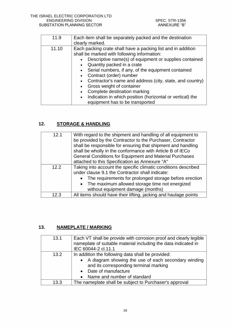
11.9 Each item shall be separately packed and the destination clearly marked.
11.10 Each packing crate shall have a packing list and in addition shall be marked with following information:
Descriptive name(s) of equipment or supplies contained
Quantity packed in a crate
Serial numbers, if any, of the equipment contained
Contract (order) number Contractor's name and address (city, state, and country) Gross weight of container Complete destination marking
Indication in which position (horizontal or vertical) the equipment has to be transported
12. STORAGE & HANDLING
12.1 With regard to the shipment and handling of all equipment to be provided by the Contractor to the Purchaser, Contractor shall be responsible for ensuring that shipment and handling shall be wholly in the conformance with Article B of IECo General Conditions for Equipment and Material Purchases attached to this Specification as Annexure "A"
12.2 Taking into account the specific climatic conditions described under clause 9.1 the Contractor shall indicate:
The requirements for prolonged storage before erection
The maximum allowed storage time not energized without equipment damage (months)
12.3 All items should have their lifting, jacking and haulage points
13. NAMEPLATE / MARKING
13.1 Each VT shall be provide with corrosion proof and clearly legible nameplate of suitable material including the data indicated in IEC 60044-2 cl.11.1
13.2 In addition the following data shall be provided:
A diagram showing the use of each secondary winding and its corresponding terminal marking
Date of manufacture
Name and number of standard
13.3 The nameplate shall be subject to Purchaser's approval
THE ISRAEL ELECTRIC CORPORATION LTD ENGINEERING DIVISION SPEC: STR-1356 SUBSTATION PLANNING SECTOR ANNEXURE “B”
29
14. NOTES Progress Reports shall be submitted in accordance with General Conditions
Annexure "A".
15. SPECIAL REQUIREMENTS 15.1. COMMENTS BY MANUFACTURER ON ANNEXURE "B"
Name of Contractor: __________________________________________________
THE ISRAEL ELECTRIC CORPORATION LTD ENGINEERING DIVISION SPEC: STR-1356 SUBSTATION PLANNING SECTOR ANNEXURE “B”
31
15.2. DEVIATIONS FROM REQUIREMENTS
Name of Contractor: __________________________________________________
Contractor is requested to describe or indicate deviations of the equipment and
accessories from all requirements in this Specification.
In case no deviations are mentioned it will be understood that Contractor's offer entirely
complies with all requirements in this Specification.
THE ISRAEL ELECTRIC CORPORATION LTD ENGINEERING DIVISION SPEC: STR-1356 SUBSTATION PLANNING SECTOR ANNEXURE “B”
31
15.3. CONFORMITY WITH PROPOSAL DOCUMENTS
Name of Contractor: __________________________________________________
Contractor hereby certifies that he agrees to all provisions of the Proposal Documents
unless exceptions are specifically and clearly listed in the Proposal and identified as
Exceptions. Contractor printed terms and conditions are not considered specific
exceptions. Any exceptions, which Contractor has taken, are listed on Page:
____________
Contractor hereby certifies that he agrees to all conditions of the cover letter of THE
ISRAEL ELECTRIC CORPORATION LIMITED, which accompanies the Proposal
Documents.
___________________________ ______________________________
Signature of Contractor Date of Proposal