Embed Size (px)
Citation preview
An IT Legacy Project Paper LABenson
©2013, VIP Club Page 1
Repertoire Cards – 24 bits
INTRODUCTION Programmers, field service engineers, test technicians, and design engineers all used pocket sized
repertoire cards as a quick reference when trouble shooting hardware or when debugging software.
As the VIP Club IT Legacy committee has been collecting documents, hardware artifacts, and career
summaries; many repertoire cards have also been donated. This paper shows and discusses several
repertoire card types for 24-bit computers and the sequence of these machines.
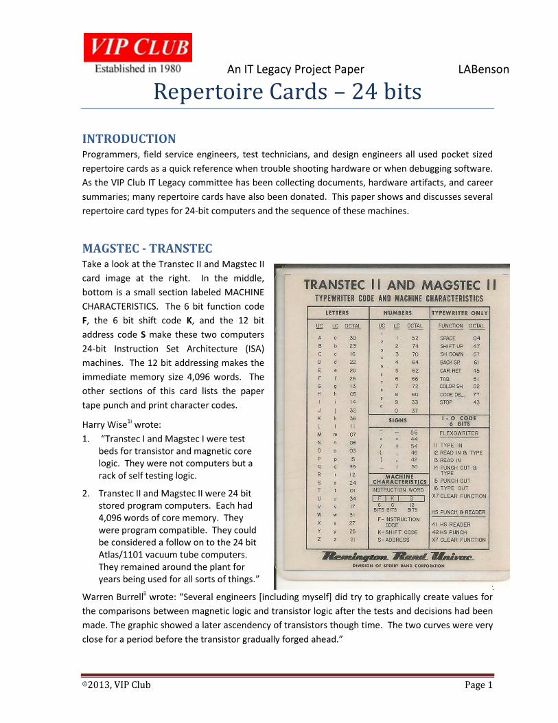
MAGSTEC - TRANSTEC Take a look at the Transtec II and Magstec II
card image at the right. In the middle,
bottom is a small section labeled MACHINE
CHARACTERISTICS. The 6 bit function code
F, the 6 bit shift code K, and the 12 bit
address code S make these two computers
24-bit Instruction Set Architecture (ISA)
machines. The 12 bit addressing makes the
immediate memory size 4,096 words. The
other sections of this card lists the paper
tape punch and print character codes.
Harry Wise1i wrote:
1. “Transtec I and Magstec I were test beds for transistor and magnetic core logic. They were not computers but a rack of self testing logic.
2. Transtec II and Magstec II were 24 bit stored program computers. Each had 4,096 words of core memory. They were program compatible. They could be considered a follow on to the 24 bit Atlas/1101 vacuum tube computers. They remained around the plant for years being used for all sorts of things.”
Warren Burrellii wrote: “Several engineers [including myself] did try to graphically create values for
the comparisons between magnetic logic and transistor logic after the tests and decisions had been
made. The graphic showed a later ascendency of transistors though time. The two curves were very
close for a period before the transistor gradually forged ahead.”
An IT Legacy Project Paper LABenson
©2013, VIP Club Page 2
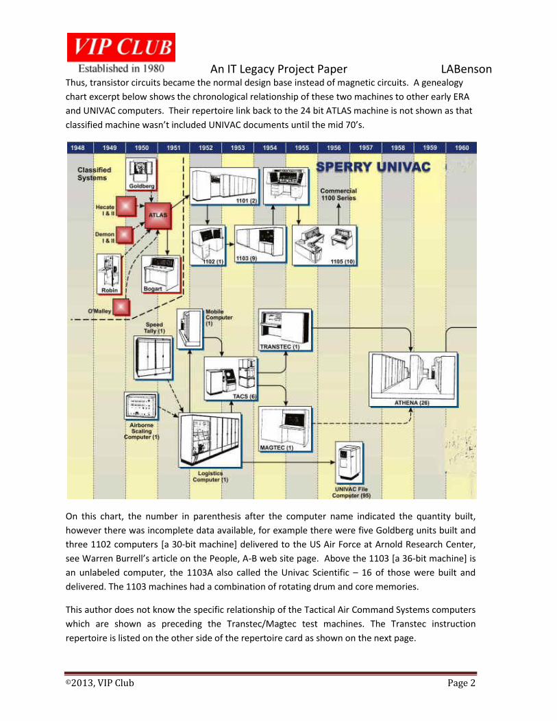
Thus, transistor circuits became the normal design base instead of magnetic circuits. A genealogy
chart excerpt below shows the chronological relationship of these two machines to other early ERA
and UNIVAC computers. Their repertoire link back to the 24 bit ATLAS machine is not shown as that
classified machine wasn’t included UNIVAC documents until the mid 70’s.
On this chart, the number in parenthesis after the computer name indicated the quantity built,
however there was incomplete data available, for example there were five Goldberg units built and
three 1102 computers [a 30-bit machine] delivered to the US Air Force at Arnold Research Center,
see Warren Burrell’s article on the People, A-B web site page. Above the 1103 [a 36-bit machine] is
an unlabeled computer, the 1103A also called the Univac Scientific – 16 of those were built and
delivered. The 1103 machines had a combination of rotating drum and core memories.
This author does not know the specific relationship of the Tactical Air Command Systems computers
which are shown as preceding the Transtec/Magtec test machines. The Transtec instruction
repertoire is listed on the other side of the repertoire card as shown on the next page.
An IT Legacy Project Paper LABenson
©2013, VIP Club Page 3
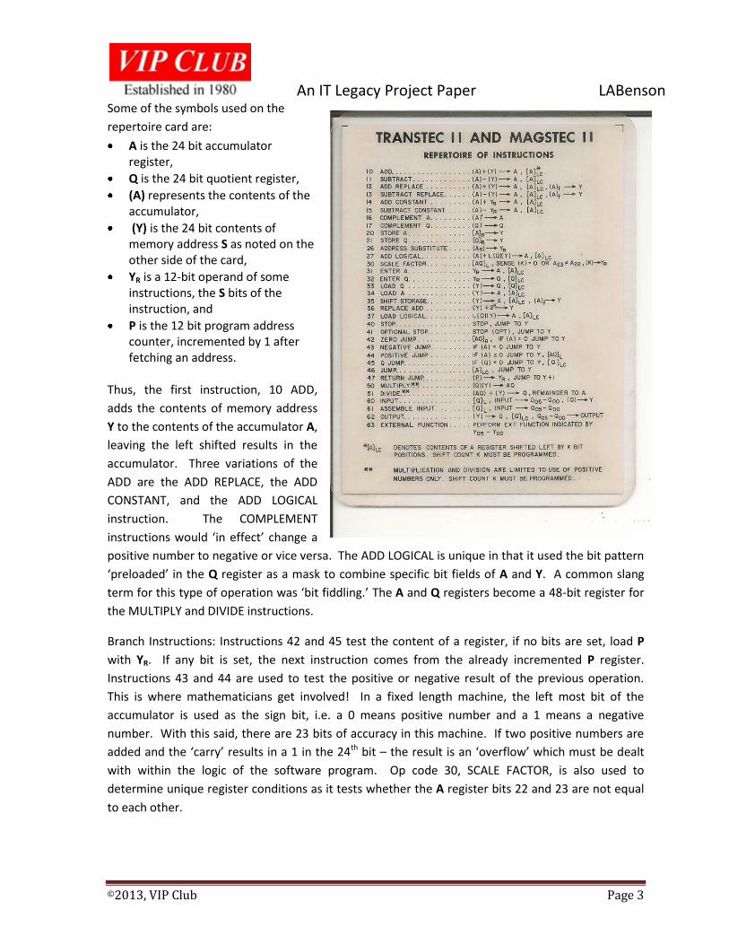
Some of the symbols used on the
repertoire card are:
A is the 24 bit accumulator register,
Q is the 24 bit quotient register,
(A) represents the contents of the accumulator,
(Y) is the 24 bit contents of memory address S as noted on the other side of the card,
YR is a 12-bit operand of some instructions, the S bits of the instruction, and
P is the 12 bit program address counter, incremented by 1 after fetching an address.
Thus, the first instruction, 10 ADD,
adds the contents of memory address
Y to the contents of the accumulator A,
leaving the left shifted results in the
accumulator. Three variations of the
ADD are the ADD REPLACE, the ADD
CONSTANT, and the ADD LOGICAL
instruction. The COMPLEMENT
instructions would ‘in effect’ change a
positive number to negative or vice versa. The ADD LOGICAL is unique in that it used the bit pattern
‘preloaded’ in the Q register as a mask to combine specific bit fields of A and Y. A common slang
term for this type of operation was ‘bit fiddling.’ The A and Q registers become a 48-bit register for
the MULTIPLY and DIVIDE instructions.
Branch Instructions: Instructions 42 and 45 test the content of a register, if no bits are set, load P
with YR. If any bit is set, the next instruction comes from the already incremented P register.
Instructions 43 and 44 are used to test the positive or negative result of the previous operation.
This is where mathematicians get involved! In a fixed length machine, the left most bit of the
accumulator is used as the sign bit, i.e. a 0 means positive number and a 1 means a negative
number. With this said, there are 23 bits of accuracy in this machine. If two positive numbers are
added and the ‘carry’ results in a 1 in the 24th bit – the result is an ‘overflow’ which must be dealt
with within the logic of the software program. Op code 30, SCALE FACTOR, is also used to
determine unique register conditions as it tests whether the A register bits 22 and 23 are not equal
to each other.
An IT Legacy Project Paper LABenson
©2013, VIP Club Page 4
Instruction code 47, RETURN JUMP, provides the main stream program with the capability of using
sub-routines and returning back to the place calling the subroutine. Instruction code 63, EXTERNAL
FUNCTION, is used to control the Flexo-writer input and output modes as well as the high speed
punch.
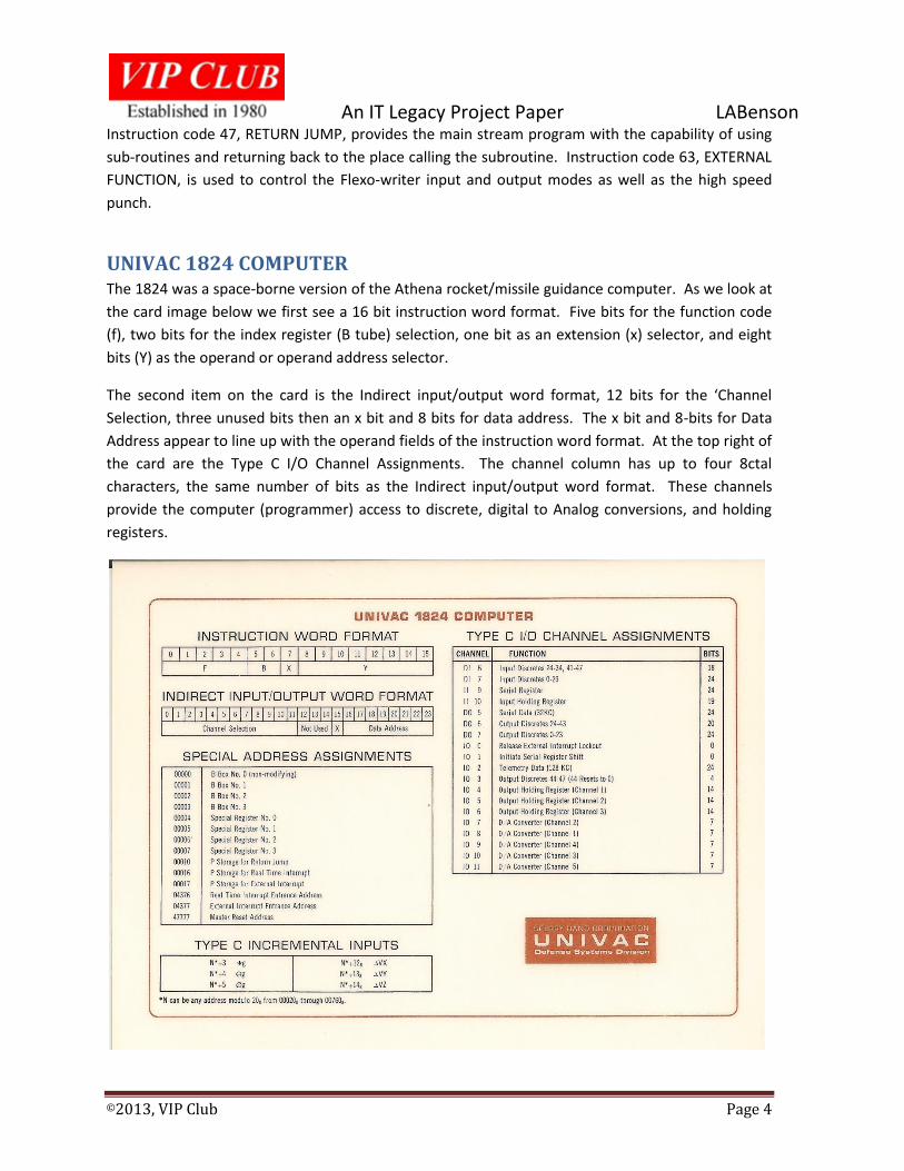
UNIVAC 1824 COMPUTER The 1824 was a space-borne version of the Athena rocket/missile guidance computer. As we look at
the card image below we first see a 16 bit instruction word format. Five bits for the function code
(f), two bits for the index register (B tube) selection, one bit as an extension (x) selector, and eight
bits (Y) as the operand or operand address selector.
The second item on the card is the Indirect input/output word format, 12 bits for the ‘Channel
Selection, three unused bits then an x bit and 8 bits for data address. The x bit and 8-bits for Data
Address appear to line up with the operand fields of the instruction word format. At the top right of
the card are the Type C I/O Channel Assignments. The channel column has up to four 8ctal
characters, the same number of bits as the Indirect input/output word format. These channels
provide the computer (programmer) access to discrete, digital to Analog conversions, and holding
registers.
An IT Legacy Project Paper LABenson
©2013, VIP Club Page 5
The Special Address Assignments are listed next on the left of this side of the card. The left column
of this table show five octal characters, 15 bits which would imply 32k of memory. The address
assignments listed imply that these are in a Random Access Memory, else the program couldn’t
function.
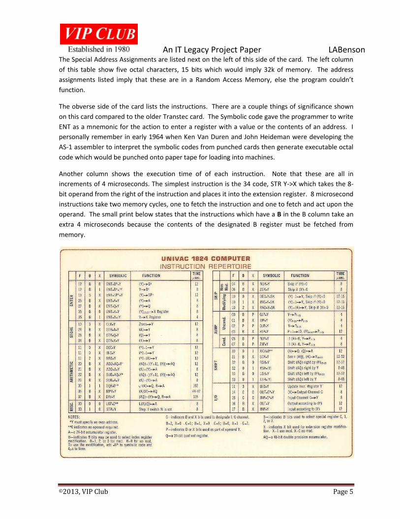
The obverse side of the card lists the instructions. There are a couple things of significance shown
on this card compared to the older Transtec card. The Symbolic code gave the programmer to write
ENT as a mnemonic for the action to enter a register with a value or the contents of an address. I
personally remember in early 1964 when Ken Van Duren and John Heideman were developing the
AS-1 assembler to interpret the symbolic codes from punched cards then generate executable octal
code which would be punched onto paper tape for loading into machines.
Another column shows the execution time of of each instruction. Note that these are all in
increments of 4 microseconds. The simplest instruction is the 34 code, STR Y->X which takes the 8-
bit operand from the right of the instruction and places it into the extension register. 8 microsecond
instructions take two memory cycles, one to fetch the instruction and one to fetch and act upon the
operand. The small print below states that the instructions which have a B in the B column take an
extra 4 microseconds because the contents of the designated B register must be fetched from
memory.
An IT Legacy Project Paper LABenson
©2013, VIP Club Page 6
The other thing that we see on this card is that the Accumulator is 24 bits as is the Quotient register.
The Divide and Multiply Instructions as well as a couple of the shift instructions use these two as a
48 bit register.
The use of only 8 bits for Y (address) of most instructions only provides a 256 word range which
means that the extension register provides the more significant bits of addresses, pointing toward
selected blocks of memory.
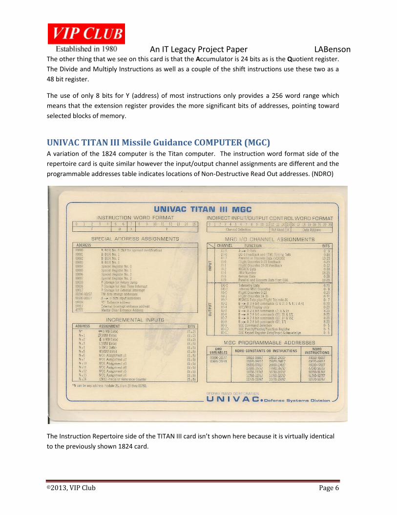
UNIVAC TITAN III Missile Guidance COMPUTER (MGC) A variation of the 1824 computer is the Titan computer. The instruction word format side of the
repertoire card is quite similar however the input/output channel assignments are different and the
programmable addresses table indicates locations of Non-Destructive Read Out addresses. (NDRO)
The Instruction Repertoire side of the TITAN III card isn’t shown here because it is virtually identical
to the previously shown 1824 card.
An IT Legacy Project Paper LABenson
©2013, VIP Club Page 7
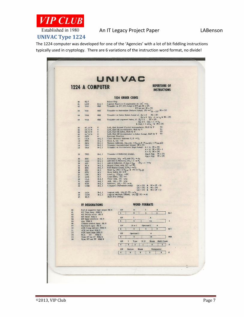
UNIVAC Type 1224 The 1224 computer was developed for one of the ‘Agencies’ with a lot of bit fiddling instructions
typically used in cryptology. There are 6 variations of the instruction word format, no divide!
An IT Legacy Project Paper LABenson
©2013, VIP Club Page 8
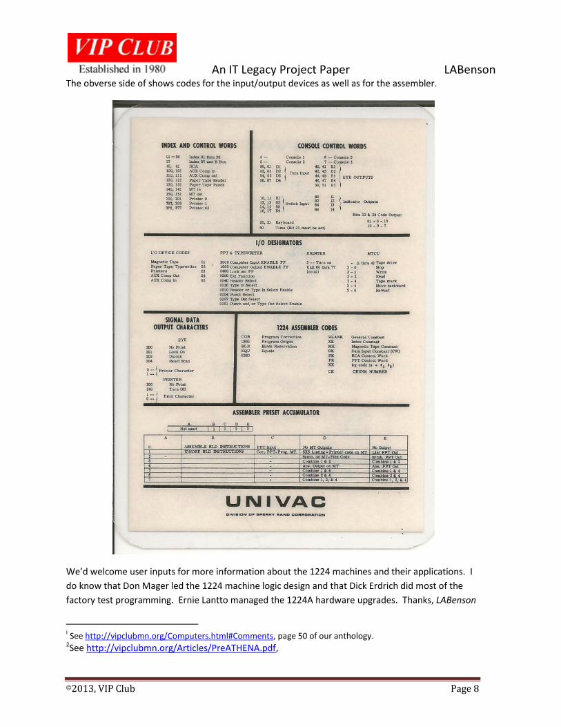
The obverse side of shows codes for the input/output devices as well as for the assembler.
We’d welcome user inputs for more information about the 1224 machines and their applications. I
do know that Don Mager led the 1224 machine logic design and that Dick Erdrich did most of the
factory test programming. Ernie Lantto managed the 1224A hardware upgrades. Thanks, LABenson
i See http://vipclubmn.org/Computers.html#Comments, page 50 of our anthology. 2See http://vipclubmn.org/Articles/PreATHENA.pdf,