Embed Size (px)
Citation preview

MIL-H-18766 (NOrd)
24 June 1955SUPERSEDEDNAVORD OS 2002P26 OCTOBER 1939
MILITARY SPECIFICATION
HYDRAULIC EQUIPMENT, ORDNANCE SHIPBOARD
(GENERAL SPECIFICATION FOR)
1. SCOPE
1.1 Scope.- This specification is intended to cover thegeneral requirements applicable to all hydraulic equipments forshipboard use under the technical control of the Bureau of Ord-nance . Requirements and information which apply to individualequipments designed for specific purposes will be furnished inthe form of detail procurement specifications or will be in-cluded directly in the procurement documents which are issuedwith invitations to bid. The requirements contained in thisspecification shall apply to shipboard ordnance hydraulicequipments when directly referred to in the detail procurementspecification of procurement documents
1.2 Classification.- The types (classification) of equip-ment shall in each case be as required by the detail procure-ment specification.
2. APPLICABLE DOCUMENTS
2.1 The following specifications, standards, drawings, andpublications, of the issue in effect on date of invitation forbids, shall form a part of this specification to the extentspecified herein:
SPECIFICATIONS
FEDERAL
FF-B-171 - Bearings, Ball, Annular, (General Purpose).FF-B-185 - Bearings, Roller, Cylindrical; and Bearings,
Roller, Self-Aligning.
Downloaded from http://www.everyspec.com

MIL-H-18766 (NOrd)
NN-B-621NN-P-515QQ-P-416QQ-Z-325LLL-B-631
- Boxes, Wood, Nailed and Lock-Corner.- Plywood, Container Grade.
Plating, Cadmium (Electrodeposited).Zinc Plating (Electrodeposited).
- Boxes; Fiber, Corrugated (For Domestic Ship-ment ) .
- Boxes; Fiber, Solid (For Domestic Shipment).- Boxes, Wood, Cleated-Plywood.- Boxes; Set-Up, Paperboard.
MILITARY
JAN-P-106 -
JAN-P-108 -
JAN-P-120 -
JAN-B-121 -JAN-P-125 -
JAN-P-127 -
JAN-P-133 -
MIL-A-140 -
MIL-S-901 -
MIL-E-2036 -
MIL-S-5049 -MIL-A-5498 -MIL-F-5504 -MIL-H-5511 -
MIL-P-5514 -
MIL-P-5516 -MIL-O-5606 -MIL-P-6889 -MIL-Z-17871 -MIL-C-15111 -
MIL-C-16173 -
Packaging and Packing for Overseas Shipment -Boxes; Wood Nailed.Packaging and Packing for Overseas Shipment -Boxes, Fiberboard (V-Board and W-Board),Exterior and Interior.Packaging and Packing for Overseas Shipment -Cartons, Folding, Paperboard.Barrier - Materials, Greaseproof’.Packaging and Packing for Overseas Shipment -Barrier-Materials, Waterproof, Flexible.Packaging and Packing for Overseas Shipment -Tape, Adhesive, Pressure-Sensitive, Water-Resistant.Packaging and Packing for Overseas Shipment -Boxes, Set-up, PaperboardAdhesive, Water-Resistant, Waterproof Barrier-Material.Shockproof Equipment. Class HI (High-Impact),Shipboard Applications, Test for.Enclosures for Electric and Electronic Equip-ment (Naval Shipboard Use).Scrapers; Hydraulic Piston Rod.Accumulators, Aircraft Hydraulic Pressure.Filters, Hydraulic, Aircraft.Hose; Aircraft, Hydraulic, Pneumatic, Fueland Oil Resistant.Packings; Installation and Gland Design ofAircraft Hydraulic and Pneumatic (GeneralSpecification for).Packings and Gaskets; Hydraulic, Aircraft.Oil; Hydraulic, Aircraft, Petroleum Base.Primer; Zinc-Chromate, For Aircraft Use.Zinc-Coating (Hot-Dip Galvanizing).Cylinders, Compressed Gas (Seamless, Non-Shatterable, for Storing Compressed Air).Corrosion Preventive, Solvent Cutback, ColdApplication.
2
Downloaded from http://www.everyspec.com

MIL-H-18766 (NOrd)
MIL-T-17113 - Tests; Shock, Vibration, and Inclination(for Electronic Equipment) General Speci-fication for.
MIL-C-17711 - Coating, Chromate, for Zinc Alloy Castingsand Hot-dipped Galvanized Surfaces.
MIL-C-17795 - Cleaning and Protecting Integral Piping
MIL-P-20085 -
NAVY DEPARTMENT
MIL-C-18487 -51 F 21 -51 F 23 -
ment.Packing, Sheet, Plant - or Animal - fiber.
Compound, Gun-slushingFluid, Power-Transmission.Fluid, Hydraulic,
BUREAU OF ORDNANCE
NAVORD OS 6341 - Miscellaneous General Design Requirements
STANDARDS
MILITARY
MIL-STD-129 - Marking for Shipment and Storage.
BUREAU OF
NAVORDNAVORDNAVORDNAVORD
NAVORD
NAVORD
ORDNANCE
OSTD 2 -OSTD 52 -OSTD 60 -OSTD 63 -
OSTD 78 -
OSTD 599 -
Method of Marking Ordnance Material.Painting of Ordnance Material.Six and Ten Splined Holes and Shafts.Piping, Tubing, and Fittings for Hy-draulic Equipment.Preparation of Ordnance Classifica-tion of Defects (NAVORD OCD's)Drafting Practice.
AMERICAN STANDARDS ASSOCIATION
ASA B-5.15 - Involute Splines.
PUBLICATIONS
ORDNANCE PAMPHLETS
OP 1 -- Preparation of Ordnance Publications.OP 400 - General Instructions for the Design, Manufacture,
and Inspection of Naval Ordnance Equipment.
3
Downloaded from http://www.everyspec.com

MIL-H-18766 (NOrd)
ORDNANCE DATA
NAVORD OD 3000 -
NAVORD OD 8999 -
Lubrication of Ordnance Equipment, In-cluding Power Transmission (Hydraulic)Fluids, Recoil and Related Flu.ids, Clean-ing and preserving Materials, Miscellane-ous Materials, and their uses.Provisioning Requirements for InitialSpares .
NATIONAL BUREAU OF STANDARDS
Handbook H28 - Screw Thread Standards for Federal Services.
(Copies of Specifications, Standards, Drawings, and publicationsrequired by contractors in connection with specific procurementfunctions should be obtained from the procuring activity or asdirected by the contracting officer. )
3* REQUIREMENTS
3.1 Materials.-. All materials used in hydraulic equipmentsshall be of high quality suitable for the purpose, and shall bespecified In accordance with the policy outlined In sections onmaterials, specifications, and standards in Standard NAVORD OSTD599 and Pamphlet OP 400.
3.1.1 Metals.-
3.1.1.1 Corrosion Protection.- Metals which are not of a cor-rosion-resist ing type, unless in constant contact with hydraulicfluid, shall be suitably protected against corrosion, Those com-ponents which are continually submerged in hydraulic fluid duringnormal operation, but which are exposed to local atmosphere duringshipment and preinstallation storage, snail be protected by theapplication of suitable coating or preservatives.
3.1.1.2 Zinc and cadmium coating.- Cadmium-plating shall notbe applied on any part of hydraulic equipment which may be incontact with hydraulic fluid. Cadmium-plating or Zinc-platingshall not be Used on surfaces of internal parts which are subjectto rubbing or abrasion. Zinc hot-dipped coating, when used,shall be in accordance with Specification MIL-Z-17871, with asupplementary chromate treatment In accordance with SpecificationMIL-C-17711. Zinc plating shall be in accordance with Specifica-tion QQ-Z-325, Type II. When used, cadmium plating shall be inaccordance with Specification QQ-P-416, Type II.
Downloaded from http://www.everyspec.com

MIL-H-18766 (NOrd)
3.1.1.3 Bearing and thread material.- Bearing and threadmaterials shall be selected with a view toward minimizing thepossibility of seizure, scratching, or galling.
3.1.1.4 Dissimilar metals.- The use of dissimilar metalsin Intimate contac t, especially brass, copper, or steel in con-tact with aluminum shall be avoided whenever possible. Wherecontacts are unavoidable, the metals shall be protected or in-sulated against corrosion.
3.1.1.5 Cast iron.- The use of cast iron is not authorizedwithout written approval of the Bureau of Ordnance for eachspecific part. Consideration will be given to the use of cer-tain cast Iron for valve blocks, if of proper design.
3.1.1.6 Non-destructive inspection.- All magnetizable,critical parts which are designed wit h a low factor of safetyshall be designated as subject to magnetic inspection,whereconsidered necessary. Such inspection shall be designated onthe drawings of the parts. Cracks or other injurious defectsshall be cause for rejection. Where necessary, other non-de-structive inspection methods shall be designated on the draw-ings of the parts.
3.1.2 Packing and gaskets.- Plant, or animal fiber sheetgaskets if used shall be in accordance with Specification MIL-P-20085. When appropriate , packings and gaskets shall be manu-factured in accordance with Specification MIL-P-5516.
3.1.3or Specilic Syst
Fluids,-ficationem. Flui
F51d C
luids conformingF 23 will normallonforming to Spec
to Specy be usificati
ification 51 Fed in the hydraon 51 F 21 shall
21u-
be used. unless otherwise specified or allowed.
3.1.3.1 Filtering.- All hydraulic fluid shall be filteredthrough a 10 -micron filter before installation in hydraulicsystems.
3.1.4 Storage life.- Synthetic rubber packings, gaskets andother component parts used shall not be over 2 years old whenthe component is submitted for acceptance under contract. Forcomponents which incorporate other organic materials that maydeteriorate with age, the contractors shall state the storagelife expectancy and submit substantiating data to support theirrecommendations .
5
Downloaded from http://www.everyspec.com

MIL-H-18766 (NOrd)
3.2 General requirements .- Hydraulic systems shall be as sim-ple, reliable, and foolproof as possible with respect to design,manufacture, inspection, Installation, operation, and maintenancecommensurate with other criteria.
3.2.1 Safety of operation.- Interlocks shall be provided toprevent improper or unintended operation of the hydraulic system.When practicable, all elements shall be designed so that any -failures or combinations of failures which may occur shall resultIn a safe condition of the hydraulic system.
3.2.2 Endurance.- The hydraulic system shall be capablesatisfactory operation during and after the endurance tests
ofin
4.2.4.9
3.2.3 Strength requirements.- Hydraulic equipment which issubject to working pressure shall be capable of withstanding ahydrostatic pressure equal to two times the maximum required re-lief valve setting, or to 1,000 pounds per square inch above themaximum required relief valve setting, whichever is the smallervalue, without external leakage or permanent deformation. Tanks ,which normally operate at approximately atmospheric pressure,shall be capable of withstanding an internal pressure of 5 poundsper square inch in excess of the maximum operating pressure inthe tank without leakage or permanent deformation. Hydraulicequipment shall be of adequate strength to withstand all surgepressures which may occur in the equipment. Tanks Subject tosurge pressure, particularly normally full tanks, should be cyl-indrical in shape when practicable, or otherwise designed to in-sure against fatigue failure induced by repeated surges.
3.2.4 Weight.- The weight of the hydraulic equipment shallbe the minimum consistent with the requirements of performance,and with other pertinent criteria.
3.2.5 Form, outline, and dimensions.- The hydraulic equip-ment shall conform generally (or exactly, if so required by thedetail specification) In form and outline to the Ordnance Draw-ings or Sketches listed in the detail specifications, and shallconform strictly to such dimensions and tolerances as appear onthose drawings, in order to ensure proper assembly and function-ing in combination with other parts of-the assemblies for whichthe equipments are intended, and in order to avoid mechanicalinterferences therewith. The hydraulic equipment must in allcases be capable of erection, inspection and servicing withinthe spaces available, as shown on the applicable drawings orsketches, and all parts shall be capable of passage through
6
Downloaded from http://www.everyspec.com

MIL-H-18766(NOrd )
the access openings to those spaces. Information on theseaccess openings will be stated in the applicable drawings ordetail specifications.
3.2.6 Protective coatings.- The protective coatings of allparts shall be that required by conditions of use and for goodappearance. Unless otherwise specified, hydraulic equipment, asfurnished by the contractor, need be painted for protective pur-poses only. Such painting shall be In accordance with the ap-plicable provisions of Standard NAVORD OSTD 52, and is requiredonly for exposed, unplated, non-working surfaces of steel,bronze, or aluminum parts.
3.2.7 Fluid Velocity.- Sizes of piping-and passages shallbe such that he velocity of fluid in pressure lines does notexceed 20 feet per second except when other considerationsjustify higher velocities. Suction lines shall be sufficientlylarge, taking bends and other restrictions into consideration,to ensure sufficient pressure at pump Intake ports at the min-imum ambient temperature.
3.2.8 Back pressure.- The hydraulic system shall be designedso that proper funct ioning of any unit shall not be affected bythe back pressure in the system.
3.2.9 Operating conditions. All hydraulic equipment shalloperate satisfactori ly under the following conditions:
3.2.9.1 Operating positions.- As prescribed in the detailspecifications .
3.2.9.2 Environmental conditions.- The hydraulic systemshall be capable of operat ion and storage under the environ-mental conditions In Specification NAVORD OS 6341, Condition11, unless otherwise specified.
3.2.9.3 Shock and vibration.- The shock of gunfire andshipboard vibrations shall not cause any hydraulic equipmentto malfunction. All equipment shall be sturdy enough to with-stand the forces or vibrations engendered by a near bomb hitor underwater explosion,
3.2.9.3.1 Shock.- Ability of the equipment to withstandshocks due to near bomb hits or underwater exposions shall bedetermined by test in accordance with Specification MIL-S-901,with the following exception: Acceptability of the equipmentwill be contingent upon the equipment withstanding the testsand performing its principal function subsequent to the shock
7
Downloaded from http://www.everyspec.com

MIL-H-18766 (NOrd)
tests . Minor damage or distortion willsuch damage or distortion can not in anyof the equipment to perform Its principawill not be required throughout or durin
be permittway Impail functiong the appl
edr
ic
provithe abFunct
ation
dingilityioningof the
shock .
3.2.9.3.2 Vibration.- Unless otherwise provided for in thedetail specifacation, the ability of the equipment to withstandvibration conditions on shipboard shall be determined by vibra-tion tests In accordance with Specification MIL-T-17113.
3.2.10 Clearances and interchangeability. - Working clearancesshall be suitable for operating temperatures between the minimum,ambient temperature and- 20 degrees Fahrenheit above the maximumoperating temperature as set by the manufacturer in response toParagraph 3.4.1.6 of this specification. So far as is practicable,all parts shall be originally Interchangeable between units ofthe same style and size. This does not preclude the replacementof items such as gearing or control valves and sleeves in matchedsets when considered necessary. All parts subject to replacementin the ordinary exigencies of service shall be made to such adegree of accuracy,as to insure interchangeability without fur-ther machinine,
3.2.11 Bearings.- Friction losses shall be minimized by theuse, wherever practicable, of ball bearings comforting to Speci-fication FF-B-171, or roller bearings conforming to SpecificationFF-B.185. Needle-type roller bearings and taper-type roller bear-ings may be used in applications where these bearings are moresuitable than either sleeve bearings or roller bearings conform-ing to Specification FF-B-185. The speeds and loads applied toeach bearing must be within the limits specified by the bearingmanufacturer.
3.2.12 Valve Springs.- The use of valve springs as a solemeans of operating valves is not considered desirable. Wheneverpracticable the breakage of a valve spring or its failure tofunction shall not interfere with the satisfactory operation ofthe equipment in or with which it is used. The valves whichoperate in units normally subject to shock, fox’ example in unitsattached to gun housings shall not be shifted unintentionallydue to the shock associated with recoil and counter-recoil.Pressure surges due to shock, operation of cylinders, or any otheroperation, shall not cause any valves to be shifted unintention-ally. All valves normally subject to shock, and held by springloaded detents must be placed with the valve axis at right anglesto the direction of predominant shock to prevent unintentionalshifting. The designed stresses in spring elements shall beheld at a sufficiently low level to ensure reliability.
8
Downloaded from http://www.everyspec.com

MIL-H-18766 (NOrd)
If practicable, spring operated valves should be provided witha differential area under pressure, or a small pressure-operatedplunger, which produces a force in the same direction as thespring force an the valves. (This is not necessarily requiredIn the case of simple spring loaded relief valves. ) Whereverpracticable, cams which operate valves shall be positive motioncams . If practicable, all slotted cams or discs, which operatein conjunction with spring loaded valves and detents) shall be..designed to produce a single oscillation of a small magnitudea short distance before the detent is in line with each slot.This oscillation will assist in freeing the valve if it tendsto stick during normal operations, or if the equipment is leftidle for long periods of time.
3.2.13 Lubrication.- Adequate provision snail be made forlubrication of all bearings and rubbing surfaces. Bushingspierced by holes for lubrications shall be positively fastenedto prevent movement where such movement would cut off lubrica-tion. If lubrication by other than the hydraulic fluid itselfis provided, standard lubricants only, as described in Publica-tion NAVORD OD 3000 shall be used unless specifically approvedby the Bureau of Ordnance.
3.2.14 Threaded fastenings.-
3.2.14.2 Form .- All screw threads used to secure one partto another shall be In accordance with Handbook H28 and its sup-plement.
5.2.14.2 Fit.- Unless otherwise specified all threads shallbe Class 2 fit or better. Studs, however, shall have threadsof Class 4 fit on “studded” ends, as opposed to "nut" ends.Other reliable methods of securing studs may be used if approvedby the Bureau of Ordnance.
3.2.14.3 Locking devices.- Through bolts with lock nutsshall be used where practicable. The use of locking devices,such as wired heads, lockwashers or special types of lock nutsfor all threaded parts, Is required. Lockwashers shall not beused Inside of hydraulic units. The working loose, in service,of threaded parts due to lack of locking devices will be con-sidered due to a defect In design. The use of set screws orlocking screws shall be avoided wherever practicable.
3.2.15 Shaft connections.- Shaft connections, including theconnections between shafts and gears, which are required totransmit power or considerable torque, or which are used whereangular accuracy or the elimination of lost motion is important,or where rotating parts are subject to frequent reversals in
Downloaded from http://www.everyspec.com

MIL-H-18766 (NOrd)
direction, shall be splined In accordance with Standard NAVORDOSTD 60, Where all mating parts are furnished by the contractor,an Involute spline in accordance with the American StandardsAssociation ASA B-5.15 standard may be used.
3.2.16 Inspection holes for gearing.- All housings containinggears shall be provided with adequately covered openings in suf-ficient number to allow visual inspection of the teeth on as manygears as practicable. Such openings shall expose to view atleast 2 gear teeth at a time. The openings, although preferable,need not be at the meshing points of the gearing, if such is im-practicable.
3.2.17 Noise and vibration.- Noise and vibration, particularlythat due to turbul ence, to rapid change of speed or direction, tocavitation of the hydraulic fluid, or to working contacts of mov-ing parts, shall be reduced to the minimum by proper design, con-sistent with other pertinent criteria. Consideration will begiven to the proposals of bidders and contractors to reduce thetransmission of noise and vibration by the use of mountings orcouplings specially designed for that purpose.
3.2.18 Prelection of’ moving parts. - Except as otherwise speci-fled or shown by the drawings or sketches listed in the applicabledetail specification, or as specifically allowed ‘by the Bureau ofordnance: all moving parts shall be enclosed in watertight hous-ings . Equipment to be installed in exposed locations on boardship shall be capable of’ withstanding the submersible (15-footsubmergence) test of Specification MIL-E-2036. Equipment to beinstalled below decks or within completely shielded enclosuresshall be capable of withstanding the watertight (3-foot submer-gence) test of Specification MIL-E-2036. The above requirementswill not normally apply to the air breather vents on the expan-sion tank, unless otherwise specified in the detail specifica-tion. However, means should be provided to prevent entrance ofspray or water-through these vents under normal conditions en-countered on board ship.
3.2.19 Leakage.- Leakage of fluid from the hydraulic systemis obtjectionable and shall be minimized, at all points wherenecessary, by the provision of collecting chambers and drainlines to the supply tank. Special consideration shall be givento the design of all parts through or past which fluid may es-cape from the hydraulic system. Shaft packings or seals andpipe fittings and connections shall be designed to Insure theminimum leakage of fluid: drip pans shall be provided wherepracticable for collecting unavoidable fluid leakage. Excess-ive fluid leakage shall be considered to constitute an unsat-
10
Downloaded from http://www.everyspec.com

MIL-H-18766 (NOrd)
isfactory cWhen practishall not bket plus 2inches.
ondition, and shallcable, bolt spacinge greater than theinches. Bolt spaci
be
depng
corrected by the contractor.access and inspection covers
th of the cover above the gas-shall not be greater than 6
3.2.19.1 Packing installation.- Packings for pipe flangesshall be in accordance with Standard NAVORD OSTD 63. When ap-plicable, the Installation and gland design for packings shouldbe in accordance with Specification MIL-P-5514.
3.2.20 Thermal expansion.- All closed circuits shall con-tain provisions to insure against excessive pressure resultingfrom thermal volumetric changes.
3.2.21 Air vents. Air vents shall be provided at all pointsin hydraulic systems where air will tend to accumulate and mayresult in unsatisfactory operation. All air vents shall be ac-cessible after final installation of the equipment on board ship.Disconnection of pipe lines or loosening of flanges does notconstitute approved air venting means.
3.2.22 Pressure gage connections.- Pressure gage connectionsshall be provided in sufficient number to permit an operatingcheck of the equipment. The connections shall be so locatedin each equipment that pressure gages can be temporarily attachedeven when the equipment Is installed on board ship. Pressuregage connections shall consist of holes tapped for and closedby lfl-inch International Pipe Standard steel pipe plugs whenthe Installation of such tapered thread plugs will not produceharmful distortion. To prevent distortion of hydraulic units,it will be permissible to use an intermediate adapter havingstraight threads and a flange with a suitable seal on one sideand a l/4-inch pipe tap on the other side for forming the gageconnection.
3.2.23 Filling and draining.- Hydraulic systems shall bearranged so as to be filled through a single properly capped,vented, and screened filling opening. This filling openingshall be so constructed that, when closed, it will not permitleakage of fluid In any required operating position. Thefiller cap shall be easily installed or removed by hand or byuse of ordinary non-powered hand tools. To prevent loss ofthe cap when removed, it shall be attached to the hydraulicunit (normally the tank) with a chain or by other suitablemeans. The use, while filling a system, of the air vents pro-vided on other parts of the hydraulic system, is permissible
Downloaded from http://www.everyspec.com

MIL-H-18766 (NOrd)
provided that the necessity for such use is clearly stated ona filling instruction plate Means shall be provided for drain-ing the hydraulic fluid from all parts of the hydraulic system.All internal pockets in which hydraulic fluid, water, sludge orother contaminants may collect shall be provided with drainswhich will permit removal of all fluids, when the equipment isin Its normal installed position. The instructions for theequipment should state the minimum frequency recommended forsuch draining procedures. Each system shall be provided witha main drain, from which substantially all the liquid In thesystem may be withdrawn with facility and without waste of liq-uid unless otherwise specified or allowed. When required by thedetail specification, provision shall be made for connection toall tanks and all large components of hydraulic systems to acentralized filling and draining system. Suitable shut-offvalves and pipe connections will be required for this purpose
3.2.23.1 Draining of compressed gas containers.- Compressedgas containers such as accumul ator air chamb ers or air flasksconnected to the accumulator, into which hydraulic fluid mayleak or which may accumulate condensed water vapor, should beprovided with adequate means for draining or “blow down" ofthese fluids, This is essential in order to reduce the possi-bility of “Diesel action" with the hydraulic fluid when recharg-ing the container with compressed air. Unless otherwise ap-proved by Bureau of Ordnance it should be possible to drainthese fluids without removing the compressed gas container fromits installed position. The draining provisions should includea slow-opening valve and a drain plug in series. When necessary,a drain pipe may be provided to avoid spilling of the drainedfluid on the adjacent equipment.
3.2.24 Cleaning of parts and system.- All parts of hydrau-lic system units shall be thoroughly cleaned prior to assemblyor installation of that unit. Each new hydraulic system shallbe operated, each unit being operated at least 10 times, for alength of time (at least 15 minutes), sufficient to insure fil-tration of all circulating fluid. Filling equipment which isuses for this cleaning process shall be provided with filterswith the same, or finer, degree of filtration uses In the hy-draulic system. Dead-end lines in the system shall be properlyconnected to clean completely such lines during actuation ofthe system. If the filter element In the hydraulic system isused during this operation, It shall be replaced.
12
Downloaded from http://www.everyspec.com
MIL-H-18766 (NOrd)
3.2.25 Marking of parts and assemblies.- Parts and assem-blies shall be marked in accordance with Standard NAVORD OSTD 2.
3.2.26 Emergency provisions.- All hydraulically operatedparts which are essential to safety, or which are required tofunction in order to permit continuation of operations until asafe condition is obtained, shall have provisions for emergencymanual operation.
3.2.27 Dangerous Operations.- All parts of the hydraulicsystem which are manually operated and which, when improperlyoperated, may endanger the safety of personnel or equipmentshall be suitably marked by attached warning plates statingthe necessary precautions to be taken to prevent injury.These parts shall also be suitably protected or designed toprevent inadvertent operation.
3.2.28 special tools.- Hydraulic systems shall be so de-signed that special tools will not be required for assemblyand disassembly of units, unless it can be shown that the useof special tools is unavoidable. In such cases, the contractorshall submit drawings of the tools with substantiating evidencejustifying the special tools before the hydraulic unit may beapproved for service use.
3.2.29 Gages.- Gages which are necessary to ensure properfits between the hydraulic equipment and the mating equipmentfurnished by the Government shall be provided in accordancewith the requirements of Publication OP 400.
3.2.30 Standard parts.- See Publication OP 400..
3.2.31 Resonant frequency.- When hydraulic power transmis-ion equipment is used as part of an automatic control system,the resonant frequency should be sufficiently high to ensuresatisfactory operation.
3.3 Component design general requirements.-
3.3.1 Hydraulic pumps.- Except when otherwise specificallyapproved for each application, all pumps furnished for hydrau-lic systems shall be of a positive displacement type. Pumpcapacities shall be as required to obtain the maximum combina-tion of speed (discharge) and torque (pressure) required bythe applicable detail specification, when operated in combina-tion with all other specified equipment. The pumps shall be ofrugged and substantial construction; they shall be designed inaccordance with the best modern practice, and shall be suited
Downloaded from http://www.everyspec.com

MIL-H-18766(NOrd)
In all respects LO perform the functions intended in an effi-cient manner. Pumps shall be designed so that they will not emitexcessive noise, particularly if due to turbulence or cavitationof the oil, to rapid change of speed or direction of the movingparts of the pump, or to the working contacts of the moving partswith each other or with the fixed parts of the pumps. Unlessotherwise approved, hydraulic pumps shall be self lubricating withno provisions other than the circulating hydraulic fluid. Thepump shall not vibrate excessively under any conditions of opera-tion at all speeds up to and including the rated speed. Over-pressure protection shall be provided on the discharge side of’all pumps. The direction of rotation of each pump shall beclearly indicated on the pump where it can be readily seen.
3.3.1.1 Power pumps.. Power pumps may be of the followingtypes:
Parallel Piston PumpsRadial Piston PumpsVane PumpsGear Pumps
The pumps shall have no deleterious pulsation or variation Indelivery at constant pressure when operating at rated speed.
3.3.1.1.1 Pressure.- Unless otherwise specified, all powerpumps shall be capab le of continuous satisfactory operation ata pressure of at least 1,000 pounds per square inch, When re-quired by the detail specification, piston type pumps shall bedesigned to be capable of operation at a pressure of at least2,500 Pounds per square inch.
3.3.1.1.2 Efficiency.- Pump efficiency (overall) at the speci-fied pressure, normal operating speed
60and approximately maximum
delivery rate shall be not less than percent, computed asfollows:
efficiency, % = 0.0583 p Q/H.P. input In whichP = pressure psi)Q = delivery (gallons per minute)
An efficiency of 75 percent in lieu of 80 percept may be accept-able for gear pumps, particularly if a reduction in noise is ob-tained. When a hydraulic pump and a hydraulic motor are usedtogether as a transmission, the overall efficiency will be statedin the detail specification.
14
Downloaded from http://www.everyspec.com
MIL-H-18766 (NOrd)
3.3.1.1.3 Neutral interlock.- Electrical interlock switchesshall be furnished with hydraulic pumps of the variable dis-charge type for the purpose of preventing the electric motorsfrom starting under load, and uncontrolled operation of theassociated drive equipments. Normally the neutral interlockswitch shall be operated by the variable discharge strokingmechanism in such a way that the switch is closed only whenthe stroking mechanism is in, or very near, the neutral posi-tion. Devices other than electrical switches may be providedto accomplish the Intent of this requirement.
3.3.1.1.4 Stroking mechanism.- The stroking mechanism, forcontrolling the rate and direction of flow of the hydraulicfluid between the variable discharge type hydraulic pump andthe hydraulic motor or cylinder, and thereby the speed anddirection of motion of the driven equipment, shall be in ac-cordance with the requirement of the detail specification.
3.3.1.2 Auxiliary pumps.- Auxiliary pumps may be used forsupercharging or replenishing systems, for control or servocircuits, and as sump pumps and oscillator pumps. Auxiliarypumps may normally operate at full capacity during the entiretime that the electric power motor is running at constant speed(that is, continuously in one direction). When the volume offluid delivered is not required for control or superchargingpurposes, the fluid shall be by-passed through a relief valveor its flow shall be reduced or limited by other. hydraulicmeans . The rate of delivery and the working pressure of aux-iliary pumps shall be determined by the designer of the hy-draulic power equipment. The power inputs to auxiliary pumpsshall be added to those of corresponding power pumps in allcomputations of overall efficiency and no-load input unlessotherwise specified. sump pumps, when required, shall operatewhen the hydraulic system is cut in to return the hydraulicfluid to the tank. Sump lines must be in the lowest portionof the hydraulic units so that the hydraulic fluid cannotenter any associated cable or other electrical compartment.
3.3.1.3 Lubrication pumps.- Lubrication pumps may be oftwo types:
(a) Uni-Directional Pumps which deliver lubricant in onedirection only regardless of the direction of rotation of thedriven end.
(b) Reversible Pumps which reverse the direction of deliv-ery of the lubricant with the reversal of direction of rota-tion of the driven end.
15
Downloaded from http://www.everyspec.com

MIL-H-18766 (NOrd)
Gear-type and vane-type auxiliary pumps may be used for lubri-cation pumps when they are driven continuously in one directionat a uniform speed of rotation suitable to this type. Workingclearances for lubrication pumps shall be suitable for the op-erating temperatures specified. The pumps shall be self-primingand shall function satisfactorily when operating at thespeed(s). The type of lubricant, the volume delivered,working pressure, and the suction liftin the detail specification.
3.3.2 Hydraulic motors.- Hydrauliclowing types:
Parallel Piston MotorsRadial Piston MotorsGear Motors
of the
motors
pump will
of
designedthebe stated
the fol-
Under constant pressure and with constant resistance, motorsshall be designed to have substantially constant speed in allpositions of rotation. Unless otherwise specified, motors shalle capable of continuous satisfactory operation at a pressuredrop of at least 1,000 pounds per square inch. When requiredby the detail specification, piston type motors shall be designedto be capable of operation at a pressure drop of at least 2,500pounds per square inch. The motor capacities and efficienciesshall be those necessary to obtain the combination. of torque andspeed required by the detail specification, when operated in com-bination with all other specified equipment.
3.3.3 Hydraulic cylinders.- Hydraulic cylinders shall be ofthe simplest pract icable design for the work intended, consistentwith other pertinent criteria. Cylinders, pistons, and pistonrods shall be sufficiently hard and corrosion resistant to ensureadequate service life. The surface finish of the cylinder boreor the piston rod sliding past packings or seals (particularlyO-rings) shall be 15 micro inches RMS or less. When required,hydraulic cylinders shall be provided with internal buffers todecelerate the moving systems attached to the piston rods. Pro-vision shall be made to clean externally sliding parts, such aspiston rods, by means of scrapers similar to those in Specifi-cation MIL-S-5049, when these exposed surfaces are subject tothe accumulation of foreign particles. If the piston rod remainsextended for long periods of time, a felt wiper shall be pro-vided for the purpose of lubricating the piston rod. Means shallbe provided for maintaining a supply of hydraulic fluid on thefelt, -without requiring disassembly of the cylinder.
Downloaded from http://www.everyspec.com

MIL-H-18766 (NOrd)
Air vents, for removing trapped air, shall be provided at thehighest point in the hydraulic cylinder in its final installedposition, when required by the design of the hydraulic system.Where practicable, a drain connection to the” tank shall be pro-vided at the piston rod end of the cylinder to remove hydraulicfluid leakage past the piston rod main seal.
3.3.4 Oil filters.- Oil filters shall be provided in all hy-draulic systems. They shall filter all of the circulating fluidin auxiliary pump and lubrication pump circuits, preferably onthe discharge side of these pumps. When required by the detailspecification, filter units shall be installed in multiple, sothat one unit can be removed for cleaning while the other re-mains operable. A selector valve shall be provided on eachmultiple (duplex) filter housing to permit selection of flow offluid through either or both filter elements. In the event thatmultiple filters are not required, suitable valves shall be in-stalled to allow for opening and cleaning the filters withoutdraining the system.Suitable relief valves shall be provided to by-pass the hydrau-lic fluid in event of excessive restriction to flow through thefilter elements. All types of’ filter elements shall be remov-able for service and inspection without disconnecting fittingsor disturbing the mountings. The degree of filtration (spacingof the filter element) shall require approval by the Bureau ofOrdnance. Oil filters shall be inert to the hydraulic fluids.
3.3.4.1 Micronic type filters.- When required by the detailspecification, micronic type filters shall be provided in hydrau-lic systems to remove from the hydraulic fluid particles of for-eign matter larger than 10 microns (0.00039-inch). In circuitshaving a small rate of flow, micronic type filters may be usedas full-flow units (that is, filtering all fluid discharged bythe pump) without requiring excessively large filters, In ap-plications using full-flow micronic filters, means should beprovided to indicate either visually or electrically (when thephysical location of the filter unit is remote) excessive re-striction to flow through the filter elements. For circuits Inwhich the rate of flow is large, micronic type filters may beused in a by-pass arrangement so that only a portion of the flowin the circuit will be filtered. Micronic t ype filters usedin a by-pass arrangement need not be installed in multiple. Mi-cronic type filters shall be in accordance with applliable por-tions of Specification MIL-F-5504.
Downloaded from http://www.everyspec.com
MIL-H-18766 (NOrd)
3.3.5 Relief valves.- Relief valves shall be provided toprotect all equipment from the effects of excessive pressure.Relief valves shall be arranged so that their settings may beadjusted In service, but so that the settings are not subjectto accidental change. In order to avoid unauthorized changesin pressure settings, which may cause damage to the equipment,adjustments which require changes in thickness of a spacer orshim will be acceptable. All plungers, balls,pistons, etc., inrelief valves shall be accurately guided to prevent cocking andjamming of the relief valve off its seat.Unless otherwise specified in the detail specification, thefollowing relationship in pressure values shall bethe design of relief valves.
Cracking pressure-91 percent (minimum)Full-flow pressure-100 percentReseat pressure-82 percent (minimum)
provided in
Hydraulic fluid vented by relief valves shall be returned to thehydraulic system.
3.3.6 Pump unloading devices.- All hydraulic systems shallbe provided with means whereby the input to the hydraulic pump,including associated auxiliaries required for its operation,under “No-load” conditions (that is, when the pump is driven atnormal operating speed without causing useful work to be per-formed by a hydraulic motor or cylinder), where the temperatureof the hydraulic fluid is approximately 120 degrees Fahrenheit,shall not exceed the value allowed by the detail specification.For variable discharge pumps, the stroking mechanism may be re-turned to neutral (thereby reducing the pump discharge to zero)for “No-load” conditions . For other hydraulic systems with con-stant discharge pumps, “No-load” conditions may be obtained byvarious methods such as:
(a) By-passing the pump discharge to tank through the di-rectional control valve when this valve Is in the neutral posi-tion.
(b) Unloading the pump through an automatic regulator insystems with accumulators.
(1) For accumulators designed so that an externalmechanical indication of the amount of liquid in the accumu-lator is provided (for example, in a piston and cylinder type,the position of the piston rod indicates the amount of fluidin the cylinder), the mechanical indication may be used to
18
Downloaded from http://www.everyspec.com

operate a directional control valve toto either the ‘tank or the accumulator,of hydraulic fluid in the accumulator.
MIL-H-18766 (NOrd)
connect the pump dischargedepending upon the amount
(2) For accumulators of the diaphragm or bag types, anautomatic pressure regulator may be used to cut-in or cut-outthe pump delivery, depending upon the pressure in the accumula-tors .
3.3.6.1 pressure regulators (unloading valves).- Pressureregulators are units which relieve pumps from working pressureloads during the time that the hydraulic system is between cut-out and cut-in range by providing free flow of the hydraulicfluid at low pressure through the pump delivery lines back tothe tank without relieving pressure from the working parts ofthe hydraulic system. The design and construction of pressureregulators shall be such that they will not be affected by backpressure or pressure surges which might tend to cause them tooperate or by-pass fluid in other than the intended manner orto become inoperative. Opening and closing of the pressureregulator shall be damped to the extent that harmful shock loadsare eliminated The internal leakage of the regulator shall beas small as practicable and shall not be sufficient to affectthe operation of any unit of the hydraulic system.
3.3.7 Directional control valves.- When specifically requiredby the detail specification, directional control valves shallbe provided to govern the direction of flow of” hydraulic fluidbetween the hydraulic pump and the hydraulic motor or cylinder.Installation and design of directional control valves shall besuch that they will not be affected by back pressure, or pres-sure surges, which might tend to cause them to open or movefrom their setting, or cause them to by-pass hydraulic fluid inother than the intended manner. The design of directional con-trol valves shall be such as to offer a minimum restriction tothe flow of hydraulic fluid. All ports on separately mounteddirectional control valves shall be clearly marked to indicatethe proper connection to be made. Directional control valves,in general, will be operated by any one or any combination ofthe following methods:
(a) Manually.(b) Mechanically or hydraulically (cams, springs, hy-
draulic pressure, etc.).(c) Electrically (solenoid, motor).
For manually operated directional controlquired to shift the valve operating lever
valves, the force re-shall not exceed 15
Downloaded from http://www.everyspec.com

MIL-H-18766 (NOrd)
pounds, unless otherwise specified in the detail specification.An instruction plate shall be mounted on each manually operateddirectional control valve, near the operating lever. This plateshall identify the unit and Indicate the direction of motion foractuation.
3.3.8 Check valves.- The design of check valves shall be suchas to offer the smallest practicable restriction to flow of thehydraulic fluid. ‘All plungers, balls, pistons, etc., shall be ac-curately guided to prevent misalignment or chattering on theirseats . The direction of flow shall be clearly and permanentlyindicated by arrows on the valve housing for individually housedunits .
3.3.9 Accumulators.- Hydraulic pressure accumulators shall benon-shatterable in accordance with Specification MIL-C-15111.The compressed gas shall be separated from the hydraulic fluidby either of two methods:
Diaphragm or bag type separator.Piston type separator.
Standard gas charging and pressure gage connections shall be pro-vided on all accumulators, ‘by means of which the pressure in thegas chamber may be read, and additonal compressed gas may be ad-mitted when necessary. For small accumulators where permanentattachment of a pressure gage connection may not be practicable,the pressure gage connection may be included as part of a separ-ate gas pre-charge gaging device or as part of the gas fillingconnection.In determining the capacity of accumulators, consideration shallbe given to the following factors:
(a) Efficient duty cycle for the hydraulic system.(b) Ability to complete a cycle in the event of electric
power-failure, in order-to obtain a safe condition for all as-sociated equipment.
(c) Effects of temperature variations (ambient air tempera-ture, hydraulic fluid temperature, and the compressed gas temper-ature.)
A manually-operated valve shall be installed between the accumu-lator and the hydraulic system to permit the accumulator pressureto be shut off from the hydraulic system. For piston type accumu-lators, this valve will normally be closed by the operator, whenthe accumulator is fully charged with hydraulic fluid, before thehydraulic pump drive motor is-de-energized. This will help reduce
20
Downloaded from http://www.everyspec.com

MIL-H-18766 (NOrd)
leakage of the compressed gas from the accumulator gas chamber.A manually operated valve shall be provided in the hydraulicsystem to permit release of the fluid pressure to the tank.This is required to permit checking of the gas pressure in theaccumulator. Each accumulator shall be provided with a perma-nently legible attached warning:
“RELEASE FLUID PRESSURE BEFORE DISCONNECTING PRESSURE LINE.RELEASE GAS AND FLUID PRESSURE BEFORE DISASSEMBLING, STORING, ORSHIPPING ACCUMULATOR.”
A warning plate shall be attached to the compressed gas fillingattachment (or to any gas filling valve which is provided aspart of the accumulator) cautioning the operator to admit com-pressed gas very slowly. Gas filling valves shall be of a slow-opening type. These precautions are required to prevent auto-ignition (diesel action) of the hydraulic fluid when compressedair is added to the accumulator.
3.3.9.1 Diaphragm and bag type accumulators.- Compressednitrogen only shall be used in daphragm and bag type accumula-tors in order to prevent possible auto-ignition of the hydrau-lic fluid in the event of puncture or failure of the separator.Compressed air may be used in case of emergency when compressednitrogen is not available, but should be replaced by nitrogen at
shall be designed to prevent extrusion of the diaphragm and bagthrough the fluid port. The separators shall be designed tohave a minimum of stretch during operation. The separators shallbe capable of 1,000,000 cycles of operation, of which 100,000cycles shall be between zero pounds per square inch and maximumpressure. The remaining 900,000 cycles shall occur between therated cut-in and cut-out pressures, controlled by an unloadingvalve . The separators of diaphragm and bag type accumulatorsshall be capable of meeting the physical property tests of Speci-fication MIL-A-5498, except that hydraulic fluid conforming toSpecification 51 F 21 may be substituted for fluid conformingto Specification MIL-O-5606, and the minimum temperature forthe bending test may be minus 20 degrees Fahrenheit instead ofminus 65 degrees Fahrenheit. However, the separator shall notbe damaged by storage at minus 80 degrees Fahrenheit. Unlessotherwise approved, cleaning and coating of internal surfacesof diaphragm and bag type accumulators shall be in accordancewith Specification MIL-C-15111, except as follows:
(a) Use only zinc chromate primer In accordance withSpecification MIL-P-6889.
(b) Coat threads in neck with corrosion preventive inaccordance with Specification MIL-C-16173.
Downloaded from http://www.everyspec.com

MIL-H-18766(NOrd)
3.3.9.2 Piston type accumulators.- Either compressed airor compressed nitrogen (preferably the latter, if available insufficient quantity may be used in piston type accumulators.Although a limited amount of hydraulic fluid on the cylinderwalls is normally exposed to the compressed gas as the pistonreciprocates In the cylinder, such fluid, in addition to thefluid which may leak past the piston packing, may eventuallycollect in the air filling passages. To prevent auto-ignition,rolls of copper screens, which absorb heat from the incomingair shock wave, should be placed In the air passages. Pro-visions shall be made for draining hydraulic fluid and waterfrom the compressed gas chamber. Drainage provisions shouldbe Installed so that draining may be accomplished without re-moving the accumulator from its installed position. When re-quired by the design and installation provision shall be madefor venting air from the hydraulic fluid chamber of the accumu-lator.To prevent corrosion inside of piston type accumulators due tothe action of the high pressure air, moisture which may be in-troduced with the air, and the hydraulic fluid, the followingprecautions shall be taken:
The interior surfaces of the compressed gas chamber shall betinned. After these surfaces have been thoroughly cleaned andpickled, they shall be subjected to the action of zinc chloride-ammonium chloride (70-30) flux, followed by flooding with moltensolder (5O tin, 50 lead) while the temperature of the forgingis between 425 degrees Fahrenheit and 440 degrees Farenheit.The tinned surfaces shall be allowed to cool without any rubbingor wiping which might reduce the thickness of the coating. Anyother tinning process proposed will require approval by theBureau of Ordnance.
The Interior surface of the hydraulic fluid chamber shall con-sist of a corrosion resistant liner such as bronze or monelmetal. The piston surface shall be of a type to resist galling(seizing) with the material of the internal surface of the cyl-inder.
3.3.10 Tanks.- Containers of hydraulic fluid in a hydraulicsystem (including “supply”, “expansion”, “surge”, or"auxiliary"tanks or “lubrication” oil reservoirs) are subject to the fol-lowing requirements:
3.3.10.l Number and capacity.- Unless otherwise specified,or allowed, no tank shall service more than one system; but asystem may require more than one tank, due to the conditionsof installation (as when space In a given location is restricted)or to the type of equipment proposed (as when necessary to pre-vent the formation of air pockets in any part of the system,to
22
Downloaded from http://www.everyspec.com

allow space for expansion andvoirs are normally completelyof a unit mounted higher than
MIL-H-18766 (NOrd)
“make-up” fluid when main reser-fllled or to Insure the Immersionthe main reservoir when such unit
requires immersion). The total capacity of a system to containhydraulic fluid shall be sufficient to meet all test require-ments (unless specifically excepted) of the detail specification.If a given system is expected by a bidder to require a greaterfluid capacity than is provided by the drawings or sketches ref-erenced in the detail specification, the additional capacityconsidered necessary shall be stated in the bid.
3.3.10.2 Lubrication oil reservoirs.- Separateoil reservoirs shall be provided when specifically
lubricationrequired by
the detail specification.
3.3.10.3 Material and construction.- Tanks may be OX” non-ferrous materials or of’ galvanized steel construction. Ifthe tank is to be fabricated, the process shall be subject tothe approval of the Bureau of Ordnance.Suitable paint coatings on tanks may be used for corrosionprotection, subject to the approval of the Bureau of Ordnance.
3.3.10.4 Filling and draining.- See paragraph 3.2.23 of thisspecification.Each tank shall be fitted with a means for indicating the levelof the fluid within, at least to the extent of showing whetheror not the fluid is being maintained at the proper level. vis-ual liquid level indicators are considered desirable, providedthat they are demonstrably visible and reliable under all normaloperating conditions, and that they are sc constructed that theirinjury cannot result in serious loss of fluid from the system.If filling connections on tanks are located close to the over-head structure, the proposed method of filling will requireapproval by the Bureau of’ Ordnance. Each tank shall be fittedwith a drain plug which will permit complete draining of allthe fluid in the tank.An instruction plate shall be attached to the tank near thefilling connection, and so located as to be easily readable.This plate shall contain simple and complete instructionsfor filling and shall include at least the following informa-tion.
this
Total fluid capacity of the system.Tank capacity (to normal level in tank)Specification of hydraulic fluid(s).
l
(d) Position of operating cylinders during fillingwill Influence the proper filling of the tank).
( hw en
23
Downloaded from http://www.everyspec.com

MIL-H-18766 (NOrd)
(e) Any other special instructions considered necessary,including condition of accumulators when filling to Indicatedlevel.
3.3.10.5 Access.- When any operating mechanisms such aspumps, valve-. , are mounted within a tank in such a way asnot to be readily removable therefrom, the tank shall have prop-erly covered hand holes to provide adequate access for the in-spection and adjustment of the mechanism mounted within.Unless otherwise required by the detail specification, it shall
be possible to adjust any relief valves mounted within tanks with-out requiring removal of the hydraulic fluid from the tank. Thismay be accomplished either by mounting the relief valve adjustmentelement above the highest level of the fluid (and by providing asuitable access opening for this adjustment), or by providing anadjusting means on the outside surface of the tank. Ample andaccessible provisions shall be made for complete cleaning of thetank.
3.3.10.6 Settling basin and oil screen.- If filters are notprovided in the hydraulic system, a settl ing basin with a remov-able oil screen shall be provided in the bottom of the expansiontank to permit metal particles, sludge, etc., to be separatedfrom the fluid. The screen shall be located so that the hydrau-lic fluid flowing Into the tank passes through it at a relativelylow velocity. Provision shall be made for removing the screenfor cleaning without loss of’ the fluid in the tank.A baffle or set of baffles shall be provided in tanks where
necessary to prevent surging of fluid or to prevent foaming orvortexing of fluid as it enters the tank from the return line.The baffles should be designed to prevent direct internal flowfrom the returning inlet to the outlet to the other componentsof the system.
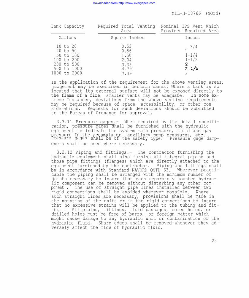
3.3.10.7 Venting of tanks.- Tanks containing combustiblefluids shall be provided with adequate venting for relief of ex-cessive internal pressure In the tanks which may occur as a re-sult of being subjected to external fire. For tanks having atest pressure of 5 pounds per square inch above atmosphere pres-sure, the following venting areas are required:
24
Downloaded from http://www.everyspec.com
MIL-H-18766 (NOrd)
Tank Capacity
Gallons
10 to 2020 to 5050 to 100
100 to 200200 to 500500 to 10001000 to 2000
Required Total VentingArea
Square Inches
0.530.861.502.043.354.797.39
Nominal IPS Vent WhichProvides Required Area
Inches
3/411-1/41-1/2
3
In the application of the requirement for the above venting areas,judgement may be exercised in certain cases. Where a tank is solocated that its external surface will not be exposed directly tothe flame of a fire, smaller vents may be adequate. In some ex-treme Instances, deviations from the above venting requirementsmay be required because of space, accessibility, or other con-siderations. Requests for such deviations should be submittedto the Bureau of Ordnance for approval.
3.3.11 Pressure gages.- When required by the detail specifi-cation, pressure gages shall be furnished with the hydraulicequipment to indicate the system main pressure, fluid and gaspressure In the accumulator, auxiliary pump pressures, etc.Pressure gages shall be of the safety type. Pressure gage damp-eners shall be used where necessary.
3.3.12 Piping and fittings.- The contractor furnishing thehydraulic equipment shall also furnish all integral piping andthose pipe fittings (flanges) which are directly attached to theequipment furnished by the contractor. Piping and fittings shallbe in accordance with Standard NAVORD OSTD 63. Wherever practi-cable the piping shall be arranged with the minimum number ofjoints necessary to insure that each separately mounted hydrau-lic component can be removed without disturbing any other com-ponent . The use of straight pipe lines installed between tworigid connections shall be avoided wherever possible. Wheresuch straight lines are necessary, provisions shall be made inthe mounting of the units or in the rigid connections to insurethat no excessive strains will be applied to the tubing and fit-tings . All piping, fittings, fluid passages, cored holes, ordrilled holes must be free of burrs, or foreign matter whichmight cause damage to any hydraulic unit or contamination of thehydraulic fluid. Sharp edges shall be removed whenever they ad-versely affect the flow of hydraulic fluid.
25
Downloaded from http://www.everyspec.com

MIL-H-18766 (NOrd)
3.3.12.1 Pipe sup Except as otherwise approved, allhydraulic piping sha be adequately supported to prevent excessivevibration and resultant fatigue failure. Provisions shall be madefor change in pipe length resulting from contraction and expansion.Supports shall be placed as close to bends as possible to minimizeoverhang of the pipe.
3.3.12.2 Swivel joints.- In parts of-hydraulic systems whererelative motion exists between two points, suitable swivel jointsmay be used If applicable. The swivel joint shall be designed sothat temperature extremes or heavy radial loads will not force thejoint out of alignment or tighten the packing to the point wherethe joint will not turn freely. The packing for the swivel jointshall be designed to provide a seal when initially assembled; andinternal pressure in the swivel joint shall increase the sealingaction. The packing shall also prevent leakage of air into theswivel joint where the internal pressure Is below atmospheric pres-sure.
3.3.12.3 Internal cleanliness.- All piping which has been heatedfor bending, welding or brazing, shall be cleaned by pickling, wire-brushing, washing and proper drying in accordance with SpecificationMIL-C-17795. This cleaning is to be done by the party performingthe bending, welding, or brazing. However, all piping shall be ex-amined and, if necessary, recleaned immediately prior to installa-tion.
3.3.13 Flexible hose.- Flexible hose, when used in hydraulicsystems, shall be in accordance with Specification MIL-H-5511.
3.3.14 Workmanship The workmanship shall be such as to meetall the requirements of the specifications and drawings.
3.4 Data requirements.-
3.4.1 Information with bids shall include the following:
3.4.1.1 Outline drawings showing the overall and principal di-mensions of the entire equipment. Wherever proper operation ofthe contractor - furnished equipment is to be contingent upon theuse of any particular design or arrangement of any Government -furnished unit, such design or arrangement is to becated.
3.4.1.2 Guaranteed maximum totalfluid . The approximate quantity ofthe system shall be stated.
weight, withouthydraulic fluid
clearly indi-
hydraulicrequired for
26
Downloaded from http://www.everyspec.com

MIL-H-18766 (NOrd)
3.4.1.3 Description, schematic diagrams, specifications, anddrawings in sufficient detail to explain clearly and completelythe operation and adjustment of the proposed equipment in con-junction with the Government - furnished equipment.
3.4.1.4 Curves of estimated minimum performance, as may berequired by the detail specification.
3.4.1.5 Pressures required to meet the specified operatingconditions .
3.4.1.6 A statement of the maximum temperature of the hydrau-lic fluid at which the hydraulic equipment will operate satis-factorily.
3.4.1.7 A statement of the ability of the proposed hydraulicequipment to operate satisfactorily under the conditions andloads stated in the detail specification when using a hydraulicfluid which meets the requirements of Specification 51 F 21,or in the case of lubricating pumps, the appropriate lubricantspecified in the detail specification.
3.4.1.8 A statement of the capacity of the tank which willmeet the requirements of the detail specification withoutcausing the temperature of the hydraulic fluid to rise abovethe value stated in response to paragraph 3.4.1.6 when theambient temperature is 110 degrees Fahrenheit.
3.4.1.9 A statement of the rated continuous and overloadpressures of the hydraulic pump, and the maximum delivery ofthe hydraulic pump at these pressures.
3.4.1.10 A detailed description of any means proposed to re-duce the transmission of noise and vibration.
3.4.1.11 A statement setting forth in detail any exceptionswhich are being taken to the detail specification, togetherwith a complete description of any proposed substitutions.
3.4.1.12 A list of additional components which are considerednecessary for the proper operation of the proposed equipment Inaccordance with the detail specification, but which are notdefinitely covered therein.
3.4.1.13 A list of the parts of the proposed equipment whichare of types that have previously demonstrated their suitabilityfor service use by being subjected to performance tests by theBureau of Ordnance.
27
Downloaded from http://www.everyspec.com

MIL-H-18766 (NOrd)
3.4.2 Drawings for design approval.- Drawings for designapproval, in accordance with Publication OP 400, are requiredunless otherwise specified. All drawings for design approvalshall be submitted at one time in order that Intelligent actionmay be tsubmissiadvance,
aken on each drawing. Theon of such drawings only wof the Bureau of Ordnance
itcontractor mayh the specifi
make partialc approval, In
3,4.2.1 Schematic diagrams.- Drawings for design approvalshall include schematic Diagrams showing the action of all com-ponent parts of the equipment In each of the various phases ofoperation, and indicating the pressure and directions of flowof fluids and the relative speeds and directions of rotation ofall gears and shafts, together with a complete description of theoperation of the equipment.
3.4.3 Instructions for installation.- Advance instructionsfor installation, in suffi cient detail to explain clearly theinstallation and-adjustment of all parts, shall accompany eachshipment of hydraulic equipment, or shall be forwarded at thesame time, under separate cover, to the same destination as theshipment. These instructions need not be in the final form re-quired in the ordnance pamphlet for the equipment, but shall besufficiently complete for the purpose intended. Four copies ofthe instructions for installation shall accompany the drawingsfor record.
3.4.4 Drawings for record.- Drawings, in accordance withPublication OP and Stmdard NAVORD OSTD 599, are requiredunless otherwise specified.
3.4.5 Ordnance pamphlet.- An ordnance pamphlet, covering thehydraulic system, shall be furnished by the contractor in accord-anice with Publication OP 1 if required by the detail specifica-tion or contract. The ordnance pamphlet shall contain a compre-hensive section on all safety precautions, and a check off liston operating and maintenance practices required to ensure safetyof the system.
3.4.6 Spare parts, tools, and accessories.- Lists of recom-mended spare parts, tools, and accessories shall be prepared inaccordance with Publication NAVORD OD 8999.
3.4.7 Ordnance classification of defects.- If required bythe detail specificati on contrac t, an ordnance classification ofdefects (OCD) shall be furnished by the contractor In accordancewith Standard NAVORD OSTD 78.
28
Downloaded from http://www.everyspec.com

MIL-H-18766 (NOrd)
4. QUALITY ASSURANCE PROVISIONS AND TEST PROCEDURES
4.1 General.- Inspection and tests will be broadly dividedinto manufacturer's shop tests and Bureau of Ordnance tests.(See Publication OP 400). Manufacturer's shop tests are fur-ther subdivided into “type” tests and “routine” tests. The“type” tests are a complete series of tests to-determine com-pliance of the design with the applicable’~pec~f~cation re-quirements, and are normally conducted on the first, or oneof the first, units produced. The "routine" tests are a lim-ited series of tests to determine whether the subsequent unitsproduced are satisfactory. The detail specification will indi-cate which tests are “type” and which are “routine” .
4.2 Manufacturer's shop tests.- Manufacturer's shop testsas follows, unless otherwise specified,or as may be further speci-fied in the detail specification, shall be conducted at thecontractor’s plant, In the presence of the Government Inspectoror his representative. The contractor shall supply all materials,equipment, and personnel necessary for the performance of thetests, unless otherwise specified.
4.2.1 Test reports.- Detailed records of the tests, clearlyIndicating quantities measured and units of measurement, shallbe kept on suitable typed or printed test sheets furnished bythe contractor, in the form of ordnance data publications (NAV-ORD OD) as specified in Publication OP 1. Copies of the testreports shall be furnished as follows at, or before, the timeof delivery of the equipment. The Government inspection shallretain the original (master) copy of the report, unless other-wise specified.
4.2.1.1 Type test report distribution.- Distribution shallbe as follows:
29
Downloaded from http://www.everyspec.com

MIL-H-18766 (NOrd)
4.2.1.2 Routine test reports.- Routine test reports of eachequipment are to be retained by the Government inspector, unlessotherwise specified. One copy of each ordnance data (NAVORD OD)publication, in reproducible form, summarizing the routine testsof hydraulic equipment furnished under each contract shall beforwarded to the Bureau of Ordnance. The summary shall list foreach routine test required by the detail specification only thehighest and lowest values found in all of the routine test re-ports for each type of hydraulic equipment.
4,2,2 General examination.- Each hydraulic system and unitthereof shall be carefully examined to determine conformancewith the detail specification with respect to the required draw-ings, materials, workmnanship, protective coatings, finish, and allother requirements not specifically called for under the test pro-cedures .
4.2.3 Hydrostatic tests.- Unless otherwise specified, all hy-draulic equipments subject to working pressure shall be subjectedto a hydrostatic pressure equal to two times the maximum requiredrelief valve setting or 1,000 pounds per square inch above themaximum required relief valve setting, whichever is the smallervalue for that part of the system, for a period of at least 10minutes. No part shall show any sign of unacceptable externalleakage, failure, malfunction, or take any permanent set duringthis test It shall be permissible during the hydraulic test toutilize external or internal stops, locks, or other means to pre-vent motion of or damage to valves, pistons, or other parts.
4.2.3.1 Hydrostatic test of tanks.- Tanks, which normallyoperate at approximately atmospheric pressure, shall be subjectedto an internal pressure of 5 pounds per square inch in excess ofthe maximum operating pressure for a period of at least 10 min-utes . Pressure surges during operation shall be taken into con-sideration in determining the maximum operating pressure. Thetanks shall show no sign of leakage during, or permanent deforma-tion after, the test.
4.2.3.2 Submergence test.- Tests shall be conducted to de-termine compliance with the requirement of paragraph 3.2.18.
4.2.4 Performance tests.- Each hydraulic system shall be sub-jetted to performance tests, including the following tests, whichWill , in general, be designated in the detail specification as“type” or “routine” tests. The hydraulic pump need not be drivenduring these tests by the electric motor intended for final in-stallation, unless specifically required.
30
.
Downloaded from http://www.everyspec.com

MIL-H-18766 (NOrd)
On all performance tests, the pertinent data shall be mea-sured and recorded at the beginning, middle, and end of’ thetests , and at suitable intervals throughout the test.The size and length of piping should be comparable to that in-
tended for the shipboard installation.
4.2.4.1 Power and efficiency.- Power and efficiency testsshall be performed in accordance with the requirements of thedetail specification.- During the tests, the arrangement andadjustment of all equipment undergoing test shall be the sameas for service Installation, unless otherwise specified orallowed. Cyclic controls causing intermittent motion may beremoved during this test.
4.2.4.2 Temperature rise.- A duty cycle will be specified inthe detail specification for the temperature rise test. The tem-perature rise at the hottest part of the hydraulic sytem shallnot be greater than the value obtained by subtracting 110 de-grees Fahrenheit (the maximum required ambient temperature forsatisfactory operation) from the maximum allowable hydraulicfluid temperature furnished by the contractor in response toparagraph- 3.4.1 .6.
4.2.4.3 No-load power loss.- With the pump being driven atits normal operat ing speed,but with the pump unloading devicefunctioning so that no useful work is being performed, a testshall be performed to demonstrate that the overall No-LoadPower Loss does not exceed that allowed by the detail specifi-cations, when the temperature of the hydraulic fluid is approx-imately 120 degrees Fahrenheit.
4.2.4.4 Noise and vibration.- Noise and vibration shall benoted during all ests . Excessive noise or vibration shall because for rejection of the equipment.
4.2.4.5 Slow speed test.- The following slow speed test willnormally be required only for hydraulic equipment which is in-tended for operation of training and elevating gears. With thehydraulic pump being driven at normal operating speed and withthe hydraulic motor output shaft delivering the torque specifiedIn the detail specification, the maximum variations of the timeof quarter turns of the output shaft, at an intended speed ofone revolution per minute (in each direction), shall not exceed20 percent of the average value. If no torque is specified, itshall be approximately equal to that developed by a hydraulicfluid pressure equal to 1/2 of the relief valve pressure set-ting l This test shall be conducted starting with the hydraulicfluid at about room temperature and then shall be repeated withthe hydraulic fluid at the maximum temperature reached during thepower arm efficiency test of paragraph 4.2.4.1
Downloaded from http://www.everyspec.com
MIL-H-18766 (NOrd)
4.2.4.6 Lubrication tests.- Lubrication of variable-dischargehydraulic pumps shall be investigated by the performance of thefollowing test, with a head of hydraulic fluid on the pump notexceeding the static head of the final Installation, except thatif supercharging means will be used In service, the pumps shallbe similarly operated during the tests:
(a) The Pump shall be rotated continuously at normal operatings p e e d u n d e r " z e r o s t r o k e .
(b) The pump shall be rotated at normal operating speed under“zero-stroke” for a total elapsed time of 50 hours during which,at 10 minute intervals, the stroking mechanism shall be movedrapidly through a complete cycle (that is, from neutral to theextreme position in one direction, then to the extreme positionin the reverse direction, and finally to neutral). During thesetests there shall be no indications as evidenced by marked changesin power consumption, noise, or otherwise, that the pump is beingexcessively worn or poorly lubricated.
4.2.4.7 Leakage tests.- The following tests shall be conductedwith hydraulic fluids conforming to Specification 51 F 21 at atemperature not less than 120 degrees Fahrenheit.
4.2.4.7.1 External leakage.- External leakage shall be mea-sured during the Endurance Tests of paragraphs 4.2.4.9.1 and4.2.4.9.2. The leakage of hydraulic fluid shall not exceed 5cubic centimeter per hour of operation for power transmissionunits or per 1,000 cycles for cyclic equipment.
4.2.4.7.2 Internal leakage.- Variable speed hydraulic powertransmission equipment shall be tested for internal leakage bylocking the hydraulic motor shaft (In its most leaky position)to prevent rotation. With the pump rotating at rated speed,measure the movement of the stroking mechanism from the neutralposition necessary to develop hydraulic pressures of 60 percentand 100 percent of the maximum continuous rated working pressurestated in response to paragraph 3.4.1.9. Measurements shall bemade on each side of the neutral position. Relief valves maybe rendered inoperative if required for this test.
To determine the dynamic leakage characteristics of the hy-draulic motor, the stroking mechanism shall be held at an anglewhich produces approximately 40 revolutions per minute of thehydraulic motor shaft under no load. Readings of hydraulicmotor speed versus differential pressure drop across the motorshall be taken at 25, 200, 400, 600, 800 and 1,000 pounds persquare inch, first in one direction and then in the other. Re-lief valves may be rendered inoperative for this test.
32
Downloaded from http://www.everyspec.com

MIL-H-18766(NOrd)
4.2.4.8 Low temperature test.- The hydraulic system shallbe tested to demonstrate its ability to start and to operatecontinuously (but not necessarily at the required speed andefficiency) at the minimum ambient temperature prescribed Inthe detail specifications, without overloading or stalling theelectric motor. The pump shall be driven by the electric motorIntended for final installation.
If the contractor has no facilities for low temperature tests,arrangements may be made for conducting this test at a Govern-ment laboratory. The information furnished with the bid shouldindicate whether or not the bidder desires to make specialarrangements for this test.
4.2.4.9 Endurance test.- Each type of hydraulic system shallbe subjected to endurance tests as described in the detail speci-fication. In general, the endurance tests will Include the fol-lowing requirements, with the hydraulic fluid temperature notless than 120 degrees Fahrenheit. The hydraulic system shalloperate satisfactorily at the end of the tests, with no failureof parts and no excessive wear during the tests.
4.2.4.9.1 Variable speed power transmissions.- The strokingmechanism of the hydrauli c pump shall be controlled by suitablemeans to oscillate with approximately simple harmonic motionabout the neutral position of the stroking mechanism. The amp-litude of this motion shall be 9/10 of the full speed displace-ment of the stroking mechanism. The period of oscillation, un-less otherwise specified In the detail specification, shall be2 seconds (on large units the period may be 4 seconds). Thehydraulic motor shall be connected to a flywheel of such momentof inertial to produce pressures equal to the maximum ratedpressure. This test shall continue for 500 hours.
4.2.4.9.2 Cyclic equipment.- Unless otherwise stated in thedetail specification, cyclic equipment, such as hoists, gunloading mechanisms, etc., shall be operated at normal cyclicrate, simulating possible extreme conditions which may be en-countered in service, for at least 50,000 cycles.
4.2.4.9.3 Accumulators.- Each type of accumulator using adiaphragm or bag separator, with the associated unloading,relief and check valves shall be operated for 1,000,000 cycles.During this test, the number of cycles in which the accumulatorfluid pressure Is reduced to zero pounds per square inch shallbe 100-,000 cycles. The remaining 900,000 cycles In which normalcycling between normal cut-in and cut-out pressures occurs shallbe controlled by the unloading valve.
33
Downloaded from http://www.everyspec.com

MIL-H-18766 (NOrd )
4.2.4.10 Jam test. - Whenever required by the detail specifica-tion, It shall be demonstrated that no part of the equipment willbe damaged if each operating unit of the hydraulic system Is stop-ped or held securely In any position of the stroke (or motion) ofthe unit, and the appropriate controls are positioned to move theunits l
4.2.4.11 Malfunction tests.- A series of control operationsshall be performed, including any possible Inadvertent or unin-tended operations, to determine any malfunctioning which couldbe encountered.
4.2.4.12 Emergency operation.- All emergency provisions inthe hydraulic system shall be operated to determine their ade-quacy .
4.2.4.13 Shock and vibration.- Each type of hydraulic equip-ment shall be tested in accordance with Specification MIL-S-901.When applicable, the detail specification will prescribe the re-quired vibration tests. Unless otherwise specified in the detailspecification, the vibration tests shall be conducted In accord-ance with Specification MIL-T-17113. If the contractor has nofacilities for conducting these tests, arrangements may be madefor their completion at a Government *facility.
4.2.4.14 -----Wear.- Each equipment submitted to type tests shallafterward be disassembled and Inspected for wear. Any wear con-sidered excessive shall be reported to the Bureau of Ordnance;it may cause the worn unit or the entire equipment to be rejected.After completion of type tests and before delivery of the equip-ment, worn parts shall be replaced as required by the inspector,and the equipment shall be subjected to routine tests.
4.3 Service tests.- Service tests, as required by the detailspecificati on, will be performed after delivery of the equip-ment . Any test required to be performed as a manufacturer’sshop test may be repeated as a service test, and when so repeated,the service test results shall be considered conclusive. Duringservice tests, all valves and other adjustable mechanism of thehydraulic system shall be at the same condition of adjustmentwith which the equipment passed the manufacturer’s shop tests.The contractor shall have the privilege of witnessing the servicetests through representatives whose appointment for such purposeshall be subject to approval of the Bureau of Ordnance.
Service tests may be sub-divided Into “type tests” which areto be performed upon representative equipments, and “routine tests”which are to be performed upon each equipment as delivered; butany “type test” may be performed as a "routine test” upon anyequipment delivered.
34
Downloaded from http://www.everyspec.com

MIL-H-18766 (NOrd)
When so specified, acceptance of an equipment will be con-tingent upon Its performance during service tests. When nototherwise specified, the replacement or repair of parts orunits shown to be defective by service tests Is covered bythe contractors guarantee. -
5. PREPARATION FOR DELIVERY
5.1 General.- Because of variations in size, shape andweight hydraulic units, the following methods of preserva-tion, packaging and packing may not be practicable for allparts of hydraulic systems. The contractor shall submit forBureau of Ordnance approval any proposals for alternative meth-ods considered more applicable or desirable.
5.2 Preservation.- Unless otherwise specified or approved,hydraulic equipment shall be cleaned internally and completelyfilled with hydraulic fluid conforming to Specification 51 F 23,and then completely sealed with suitable closures. When ship-ment of a filled system is not practicable, thin film protec-tion of Internal surfaces in accordance with Specification MIL-C-16173, Grade 2 is acceptable.All pipe flanges shall be sealed for shipping purposes by
plates extending over the entire flange area instead of by discscentered in the gasket area. Piston rods shall be placed In aretracted position and the remaining exposed surface shall becoated with rust-preventative compound conforming to Specifica-tion MIL-C-16173, Grade 2. The piston rods shall then be com-pletely wrapped with moldable Grade C paper confirming to Spec-ification JAN-B-121. Exterior bare metal surfaces shall beprotected from corrosion by coating with Compound conformingto Specification MIL-C-16173, Grade 2, when the equipment willbe boxed and stored indoors. For exterior bare metal surfaceson equipment which may be stored outdoors in an unboxed condi-tion, these surfaces shall be coated with gun slushing compoundconforming to Specification 14 C 8. Projecting parts, such asdrive shafts, shall be covered with a suitable protective coverto prevent possible mechanical damage. Preservation of spareparts shall be in accordance with instructions furnished by theOrdnance Supply Office.
5.3 Packaging.- Each hydraulic unit, unless otherwise spec-ified or approved, shall be wrapped in greaseproof paper Specif-ication JAN-B-121 Grade A and sealed with tape, SpecificationJAN-P-127. For overseas packaging, the wrapped equipment shallbe cushioned and packaged in a paperboard box conformingSpecification JAN-P-120 or JAN-P-133 or a fiberboard box
tocon-
35
Downloaded from http://www.everyspec.com

MIL-H-L8766 (NOrd)
forming to Specification JAN-P-108. For domestic packaging, thefollowing Specifications apply: LLL-B-631, LLL-B-636, and PPP-B-676. For heavy equipment wooden boxes in accordance with Speci-fication PPP-B-601 or NN-B-621, may be required to provide ade-quate protection.
5.3.1 Weight limitations.- Unless the weight of a single itemexceeds the weight limitations specified herein, the gross weightof an individual shipping container shall not exceed 200 poundsfor domestic shipment and 150 pounds for overseas shipment. Forfiberboard boxes the gross limitation shall not exceed the weightshown on the box maker's certificate. Where weight limitationsshown on the box maker's certificate exceed those shown in theapplicable box specification, the limitations of the specificationshall apply.
5.4 Packing,- Unless otherwise specified, all items shall re-ceive domestic packing. Each container shall be designed to en-close the contents’in a snug, tight fitting manner.
5.4.1 Domestic packing.- Unless otherwise specified, Interiorpackages shall be packed in substantial containers so constructedas to insure acceptance by common or other carrier for safe trans-portation at the lowest rate to the point of delivery. When fiber-board exterior containers are used, such containers shall be fab-ricated from fiberboard having a Mullen test of 275 pounds ormore. Containers shall be able to withstand storage, rehandling,and reshipment without the necessity of repacking.
5.4.2 Overseas packing.- Unless otherwise specified, for over-seas packing the interior containers shall be packed in an ex-terior shipping container in accordance with Specification PPP-B-601 or JAN-P-106. All plywood, when used, shall conform toSpecification NN-P-515, Type I or II, Class 2. Each exteriorcontainer shall be furnished with a sealed case liner fabricatedfrom barrier material meeting the requirements of SpecificationJAN-P-125. All seams and closures of the case liner shall besealed with adhesive in accordance with Specification MIL-A-140.
5.5 Marking.- Marking of unit, intermediate, and shipping con-tainers shall be accomplished in accordance with Standard MIL-STD-129. Wherever the nature of the unit package is such that itdoes not lend Itself to stenciling or where the use of a label isImpracticable, a leather, metal, waterproofed cloth, or water-proofed shipping tag bearing the required markings shall be used.
36
Downloaded from http://www.everyspec.com
MIL-H-18766 (NOrd)
6, NOTES
6.1 Intended use.- This specification may be used for anyof the foll owing purposes:
(a) As a guide in the preparation of detail specifica-tions for the development, design, and test of hydraulic systems.Applicable portions of this general specification may be incor-porated directly Into the detail specification.
(b) As a reference specification. The detail specifica-tions may refer to applicable paragraphs of this general speci-fication.
(c) As a procurement specification for specific (usuallysimple) components of hydraulic systems when the necessary de-tailed requirements needed to supplement the general requirementscan be adequately covered by relatively brief statements in thecontract.
6.2 Deviations.- The requirements of this specification aregenerally applicable to shipboard ordnance hydraulic systems andare based upon service experience to date. Deviations from theserequirements, when included in a specific detail specification,will be considered by the Bureau of Ordnance upon the presenta-tion of substantiating data by the bidder or contractor.
Patent notice: When Government drawings, specifications orother data are used for any purpose other than in connectionwith a definitely related Government procurement operation, theUnited States Government thereby incurs no responsibility norany obligation whatsoever; and the fact that the Governmentmay have formulated, furnished, or in any way supplied the saiddrawings, specifications , or other data is not to be regardedby implication or otherwise as In any manner licensing theholder or any other person or corporation, or conveying anyrights or permission to manufacture, use, or sell any patentedinvention that may in any way be related thereto.
37
Downloaded from http://www.everyspec.com

Downloaded from http://www.everyspec.com

Downloaded from http://www.everyspec.com

Downloaded from http://www.everyspec.com