Embed Size (px)
Citation preview

AD
VA
NC
ED
MA
TE
RIA
LS
& P
RO
CE
SS
ES
| A
PR
IL 2
01
52 4
SOLVING PROBLEMS IN
HUMAN/LEGAL DOMAINS
USING FAILURE ANALYSIS
METHODSDifculty in clearly and quantitatively answering questions concerning a component or product failure can lead to courtroom debates, arguments, and battles.Priyadarshan Manohar,* Robert Morris University, Moon Township, Pa.
When a product or system failure
occurs, it can have unfortunate conse-
quences, such as lost productivity and
negative effects on customer loyalty,
not to mention serious injury or loss of
life. Therefore, the total cost of failure
depends on the specific nature of all
damage incurred. In cases where there
is disagreement over who is to blame,
the dispute might go to a court of law
where several important aspects of
the failure analysis (FA) are tested, dis-
cussed, and judged. Aspects to consider
include:
• Did the investigative FA methodolo-
gy follow accepted scientific proce-
dures, such as those established by
national and international agencies,
and relevant industry codes, stan-
dards, and specifications?
• Was the evidence protected via
chain of command documentation?
• Were appropriate protocols es-
tablished and agreed upon by all
parties involved regarding evidence
collection and testing?
• Was the sequence and chronology
of failure events established?
• Were all parties involved in the
design, manufacturing, assembly,
commissioning/construction, use,
and maintenance of the product/
system identified?
• Were the reason(s) for failure de-
termined with reasonable scientific
certainty?
• What amount of damages should be
awarded to victims?
• Is the responsibility of the failure
shared, determined, and agreed
upon?
These issues can be contentious,
leading to keen legal debate and argu-
ments to determine product liability. Ar-
guments are based on failure analysis re-
ports and expert testimonies, which must
withstand both direct and cross exam-
ination. This can be a daunting situation
for FA professionals, who might not be fa-
miliar with legal jargon and procedures.
Further, although the questions raised
above are important, they do not neces-
sarily have straightforward answers. The
case studies examined here identify and
describe technical procedures to assist
with explaining complex situations and
thereby assist in solving failure analysis
problems. These examples show that
the kinetics of metallurgical reactions,
phenomena, and phase transformations
including corrosion, fatigue, creep, grain
growth, and heat treatment—coupled
with fractographic analyses and math-
ematical modeling—can be adapted to
find answers to important questions in
the legal/human domains.
Fig. 1 — Surface of a freshly baked bread roll shows black deposits at regular intervals. FTIR
spectroscopic analysis determined that burnt deposits are associated with corn meal used as a
release agent during the baking process.
*Member of ASM International

AD
VA
NC
ED
MA
TE
RIA
LS
& P
RO
CE
SS
ES
| AP
RIL
20
15
2 5
PRODUCT CONTAMINATION
A manufacturer of industrial-scale
bakery equipment was advised of a
problem where bread rolls produced
in its equipment were contaminated
by black marks on the bread’s surface
(Fig. 1). Relevant questions in this case
include: Is contamination on bread rolls
related to the machine, operator, work
environment, or processing variables?
Is it a health hazard? The chemical
analysis of the contaminant was deter-
mined using Fourier transform infrared
(FTIR) spectroscopic analysis.
FTIR reveals that the black marks
are associated with burning/overheating
of corn meal used as a release agent in
the baking process. Further investigation
determined that the conveyor belt mesh
cleaning system was not effective in re-
moving excessive corn meal that stuck to
the mesh, which eventually burned and
stuck to the dough surface and created
the black marks. Thus it is clear that the
black marks were not due to defects in
the manufacturing process, nor a faulty
design, but were caused by inadequate
maintenance of cleaning equipment du-
ring continuous operation.
PREMATURE HEATING
ELEMENT FAILUREHeating elements failed in a furnace
that had a specified maximum operating
temperature of 1200°F, which translat-
ed to a heating element temperature of
1825°F. The user claimed the elements
failed even though the maximum tem-
perature of the furnace was never set
higher than 1200°F. Relevant questions
regarding this failure include: Is the heat-
ing element material at fault? Is it the
heat treater’s error? Is it due to a faulty
temperature sensor/controller? Is it due
to operator error of inadvertently setting
the furnace temperature too high? How
high did the temperature go before the
element failed? The answers to these
questions were determined using optical
metallography as shown in Fig. 2.
The heating element material was
a Ni-Cr-Fe base electrical-resistor ma-
terial containing 0.014% Ti, 0.043% Nb,
0.029% C, and 0.006% N. Microalloy
precipitates coarsen or melt[2-6] at high
temperatures and therefore do not pre-
vent grain growth, which sometimes
leads to abnormal growth. The tem-
perature of the elements must have
exceeded 1900°F for niobium nitride/
carbonitride precipitates in this materi-
al to go into solution. The normal heat-
ing element operating temperature was
1825°F maximum, meaning the heating
element probably failed due to abnor-
mal operating conditions of excessive
furnace temperature, either due to a
faulty temperature setting or faulty tem-
perature sensor/controller.
INJECTION NOZZLE
FATIGUE FAILUREMetal quality is an important fac-
tor in machine component failure, such
as the injection molding machine at
the center of this case. Visual and ste-
reomicroscopic examination of crack
interfaces of the component revealed
that cracking occurred due to metal fa-
tigue initiated at multiple locations on
the fillet radii of two threads on the out-
side surface (Fig. 3). Fracture surfaces
did not reveal any corrosion products,
abnormal contact patterns, or temper
colors, suggesting that component op-
erating conditions during service were
not aggressive.
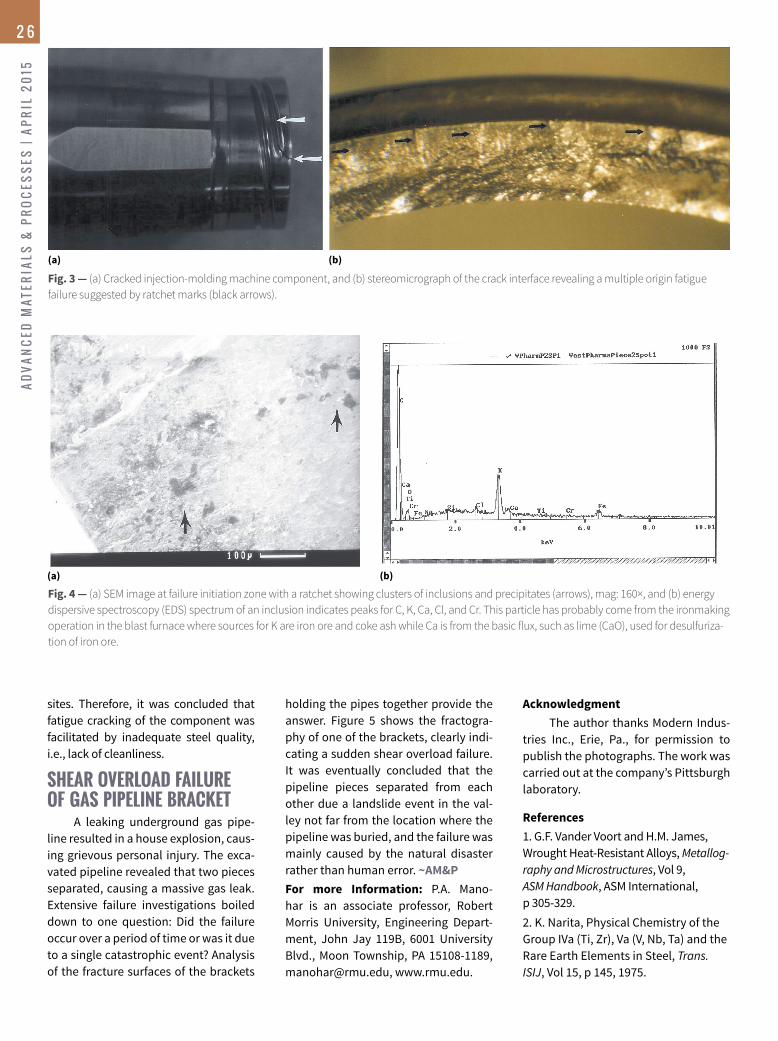
Metallurgical examination indicat-
ed that the material’s heat treatment,
microstructure, hardness, and bulk
chemical composition met relevant
standards and drawing specifications.
However, a large cluster of coarse non-
metallic inclusions was observed at one
location in the microstructure (Fig. 4).
Scattered, large inclusions were also ob-
served in other locations. Electron mi-
croscopy of the fracture surface reveals
a large number of secondary-phase par-
ticles and inclusions clustered around
crack initiation regions. Most of these
particles contained Cr, C, S, and Si, sug-
gesting that chromium carbide precipi-
tated on preexisting silicate and sulfide
inclusions.
One of the particles had a glassy
appearance and contained significant
amounts of C, K, and Ca. This particle
is most likely from the ironmaking op-
eration in the blast furnace. Sources for
K are iron ore and coke ash, while Ca
comes from the basic flux, such as lime
(CaO) used for desulfurizing iron. Large
clustered inclusions in a material signifi-
cantly decrease its fatigue resistance and
toughness by serving as crack initiation
(a) (b)
(c)
Fig. 2 — (a) Microstructure of original heating element showing fine-grained austenite, mag:
100×; (b) microstructure of used heating element showing coarse-grained austenite, mag: 100x;
and (c) example of a mixed microstructure and abnormal grain growth in the failed heating
element (A = coarse grains, B = fine grains; mag: 200×). Etchant was modified Marble’s reagent[1].
AD
VA
NC
ED
MA
TE
RIA
LS
& P
RO
CE
SS
ES
| A
PR
IL 2
01
52 6
sites. Therefore, it was concluded that
fatigue cracking of the component was
facilitated by inadequate steel quality,
i.e., lack of cleanliness.
SHEAR OVERLOAD FAILURE
OF GAS PIPELINE BRACKETA leaking underground gas pipe-
line resulted in a house explosion, caus-
ing grievous personal injury. The exca-
vated pipeline revealed that two pieces
separated, causing a massive gas leak.
Extensive failure investigations boiled
down to one question: Did the failure
occur over a period of time or was it due
to a single catastrophic event? Analysis
of the fracture surfaces of the brackets
Fig. 3 — (a) Cracked injection-molding machine component, and (b) stereomicrograph of the crack interface revealing a multiple origin fatigue
failure suggested by ratchet marks (black arrows).
(a) (b)
(a) (b)
Fig. 4 — (a) SEM image at failure initiation zone with a ratchet showing clusters of inclusions and precipitates (arrows), mag: 160×, and (b) energy
dispersive spectroscopy (EDS) spectrum of an inclusion indicates peaks for C, K, Ca, Cl, and Cr. This particle has probably come from the ironmaking
operation in the blast furnace where sources for K are iron ore and coke ash while Ca is from the basic flux, such as lime (CaO), used for desulfuriza-
tion of iron ore.
holding the pipes together provide the
answer. Figure 5 shows the fractogra-
phy of one of the brackets, clearly indi-
cating a sudden shear overload failure.
It was eventually concluded that the
pipeline pieces separated from each
other due a landslide event in the val-
ley not far from the location where the
pipeline was buried, and the failure was
mainly caused by the natural disaster
rather than human error. ~AM&P
For more Information: P.A. Mano-
har is an associate professor, Robert
Morris University, Engineering Depart-
ment, John Jay 119B, 6001 University
Blvd., Moon Township, PA 15108-1189,
[email protected], www.rmu.edu.
Acknowledgment
The author thanks Modern Indus-
tries Inc., Erie, Pa., for permission to
publish the photographs. The work was
carried out at the company’s Pittsburgh
laboratory.
References
1. G.F. Vander Voort and H.M. James,
Wrought Heat-Resistant Alloys, Metallog-
raphy and Microstructures, Vol 9,
ASM Handbook, ASM International,
p 305-329.
2. K. Narita, Physical Chemistry of the
Group IVa (Ti, Zr), Va (V, Nb, Ta) and the
Rare Earth Elements in Steel, Trans.
ISIJ, Vol 15, p 145, 1975.

AD
VA
NC
ED
MA
TE
RIA
LS
& P
RO
CE
SS
ES
| AP
RIL
20
15
2 7
Fig. 5 — SEM fracture surface of bracket showing a mixed fracture mode of shear dimples and
transgranular cleavage. Deformation lines (river pattern) on the cleavage surface of crystals are
marked by red arrows. Mag: 6000×.
3. V.K. Lakshmanan and J.S. Kirkaldy,
Solubility Product for NbC in Austenite,
Metall. Trans. A, ASM International,
Vol 15A, p 541, 1984.
4. P.D. Hodgson R.K. Gibbs, A Mathe-
matical Model to Predict the Mechan-
ical Properties of the Hot Rolled C-Mn
and Microalloyed Steels, ISIJ Intl.,
Vol 32, p 1329, 1992.
5. W. Roberts, Proc. Intl. Conf. on HSLA
Steels: Technology and Applications,
ASM International, p 33, 1983.
6. P.A. Manohar, Grain Growth and
Continuous Cooling Transformation
Behavior of Austenite in Microalloyed
Steels Containing Ti, Nb, Mn and Mo,
Ph.D. Thesis, University of Wollongong,
Australia, 1997.
www.usasymposium.com/Nsmms
www.usasymposium.com/cRasTE
• AdditiveManufacturing• GroundTesting&DiagnosticsforMaterialsScreening• Hypersonics• InnovationsinMaterials• Missiles&MissileDefense• Pico/NanoOrbital&Sub-OrbitalConceptsandCapabilitiesfromSmallLaunchVehiclestoHighAltitudeBalloons• PlanetaryOrbitandExplorationTechnologies• Range&GroundOperations• ReducingCost,IncreasingSafety• Small-SatDevelopment:GuidanceCommunication,Propulsion,In-OrbitTesting,EnvironmentQualifcation• SpaceAccess&Propulsion• SpaceMaterialsExperiments,Modeling&Simulation
NSMMSandCRASTEbringtogethertechnologists,users,anddecisionmakerstodiscusskeytechnologyissuesrelatedtospace,missile,andhypersonicsystemsandavarietyofground-breakingcommercialspacetopicsnecessaryforourCountry’sdefenseandresearchanddevelopmentpursuits.Topicsinclude:
ExtensometersStrain measurement for materials testing
Compatible with allmajor test systems
• Measuring ranges from 1% to 2000% strain
• Gauge lengths from 0.125 to 10+ inches (3 to 250+ mm)
• Temperature ranges from -265 to 1600°C
• Laser extensometers
3975 South Highway 89
Jackson, WY 83001 USA
307 733 - 8360
www.epsilontech.com
Over
30 models
to cover all
common tests
ISO 17025