Embed Size (px)
Citation preview

Specification/Especificación 24097-PT-001Rev.1
Page/Página 2 de 311F:\Engrg_Electrical\Spec\PT-001\PRE-OP-REV.0\PRE-OPSTE-RO.DOC
This Specification is divided into six Partsas follows:
Estas Especificaciones se dividen en seisPartes como se describe a continuación:
PART I GENERAL INFORMATION AND REQUIREMENTS
PARTE I INFORMACION GENERAL Y REQUERIMIENTOS
PART II PROCEDURES PARTE II PROCEDIMIENTOS
PART III PRE-OPERATIONAL / TURNOVER PACKAGES
PARTE III PAQUETES PREOPERACIONALES Y DE ROTACION
PART IV CHECKLIST FOR PLANTCOMPLETION
PARTE IV LISTA DE CONTROL PARALA TERMINACION DE LA PLANTA
PART V SYSTEM AND EQUIPMENTSAFETY TAGGING/ LOCKOUT
PARTE V BLOQUEO/ETIQUETADO DESEGURIDAD DE EQUIPOS Y SISTEMAS
PART VI ATTACHMENTS PARTE VI ANEXOS
Specification/Especificación 24097-PT-001Rev.1
Page/Página 3 de 311F:\Engrg_Electrical\Spec\PT-001\PRE-OP-REV.0\PRE-OPSTE-RO.DOC
TABLE OF CONTENTSINDICE
PART I 8PARTE I 8GENERAL INFORMATION AND REQUIREMENTS 8INFORMACION GENERAL Y REQUERIMIENTOS 81.0 SCOPE 81.0 ALCANCE 82.0 RESPONSIBILITIES 132.0 RESPONSABILIDADES 133.0 ADMINISRATION AND SUPERVISION 213.0 ADMINISTRACION Y SUPERVISION 214.0 COMMUNICATIONS 214.0 COMUNICACIONES 215.0 DOCUMENTATION 225.0 DOCUMENTACION 22
PART II 35PARTE II 35PROCEDURES 35PROCEDIMIENTOS 356.0 SAFETY TAGGING AND CLEARANCE DESCRIPTION 35
DESCRIPCION DE ETIQUETADO DE SEGURIDAD Y AUTORIZACIONES 357.0 TURN-OVER 41
ENTREGA 418.0 CLEANLINESS 43
LIMPIEZA 439.0 LUBRICATION 46
LUBRICACION 4610.0 CONTAINMENT 48
CONTENCION 4811.0 FLUSHING 50
LIMPIEZA POR DESCARGA DE AGUA 5012.0 ELECTRICAL 54
ELECTRICOS 5413.0 INSTRUMENTATION 77
INSTRUMENTACION 7714.0 MECHANICAL 89
MECANICA 89
PART III 93PARTE III 93PRE-OPERATIONAL/TURNOVER PACKAGES 93PAQUETES PREOPERACIONALES DE ENTREGA 9315.0 GENERAL 93
GENERALIDADES 9316.0 PRE-OPERATIONAL/TURNOVER PACKAGES 94
PAQUETES PREOPERACIONALES/DE ENTREGA 94
PART IV 95PARTE IV 95CHECKLIST FOR PLANT COMPLETION 95LISTA DE VERIFICACION PARA LA TERMINACION DE LA PLANTA 951.0 MANUFACTURER OF VENDOR SERVICE ASSSTANCE 95
Specification/Especificación 24097-PT-001Rev.1
Page/Página 4 de 311F:\Engrg_Electrical\Spec\PT-001\PRE-OP-REV.0\PRE-OPSTE-RO.DOC
1.0 SERVICIO DE ASISTENCIA DEL PROVEEDOR O FABRICANTE 952.0 PERMITS 952.0 PERMISOS 953.0 INSTRUCTIONS 963.0 INSTRUCCIONES 964.0 REMOVAL OF CORROSION PREVENTIVES 964.0 QUITAR LAS SUSTANCIAS ANTICORROSIVAS 965.0 FUELS AND LUBRICANTS 975.0 COMBUSTIBLES Y LUBRICANTES 976.0 REMOVAL OF TEMPORARY BRACING AND SUPPORTS 1006.0 QUITAR LOS APOYOS Y ARROSTRIAMIENTOS TEMPORARIOS 1007.0 ROTATION AND ALIGNMENT 1007.0 ALINEACION Y ROTACION 1008.0 LEAK AND PRESSURE TESTS 1018.0 PRUEBAS DE PERDIDA Y DE PRESION 1019.0 INSPECTION 1029.0 INSPECCION 10210.0 FLUSHING AND CLEANING OPERATIONS 10210.0 OPERACIONES DE LIMPIEZA POR DESCARGA DE AGUA Y OTRAS 10211.0 CONTAINMENT 10511.0 CONFINAMIENTO 10512.0 ELECTRICAL 10712.0 ELECTRICOS 10713.0 INSTRUMENTATION 12013.0 INSTRUMENTACION 12014.0 MECHANICAL 12914.0 MECANICA 12915.0 HOUSEKEEPING 13315.0 MANEJO DEL LUGAR 13316.0 DOCUMENTATION 13416.0 DOCUMENTACION 13417.0 SAFETY TAGGING 13717.0 ETIQUETADO DE SEGURIDAD 13718.0 CLEANLINESS 13918.0 LIMPIEZA 139
PART V 142SYSTEM AND EQUIPMENT SAFETY TAGGING/LOCKOUT 142PARTE V 142ETIQUETADO DE SEGURIDAD/BLOQUEO DE SISTEMAS Y EQUIPOS 1421.0 PURPOSE 1421.0 PROPOSITO 1422.0 SCOPE 1422.0 ALCANCE 1423.0 DEFINITIONS 1433.0 DEFINICIONES 1434.0 REFERENCES 1444.0 REFERENCIAS 1445.0 RESPONSIBILITIES 1445.0 RESPONSABILIDADES 1446.0 REQUIREMENTS 1486.0 REQUERIMIENTOS 148ATTACHMENTS A - SYSTEM AND EQUIPMENT SAFETY TAGGING/LOCKOUT 161ANEXOS A – ETIQUETADO DE SEGURIDAD/BLOQUEO DE SISTEMAS Y EQUIPOS 166ATTACHMENT B – SYSTEM/COMPONENT SAFETY TAGGING PERMIT 171ANEXO B –PERMISO DE ETIQUETADO DE SEGURIDAD DE SISTEMAS/COMPONENTES 172

Specification/Especificación 24097-PT-001Rev.1
Page/Página 5 de 311F:\Engrg_Electrical\Spec\PT-001\PRE-OP-REV.0\PRE-OPSTE-RO.DOC
ATTACHMENT C – DANGER – DO NOT OPERATE TAG 176ATTACHMENT D – CAUTION – RESTRICTED OPERATION TAG 177ANEXO C – PELIGRO – ETIQUETA DE NO OPERAR 178ANEXO D – PRECAUCION – ETIQUETA DE OPERACION RESTRINGIDA 179
PART VI 180ATTACHMENTS 180FORM NO. DESCRIPTION
01 CERTIFICATE OF CONSTRUCTION RELEASE 18202 VENDOR DAILY ACTIVITY SUMMARY 18303 VENDOR TIME SHEET 18404 VENDOR END OF SERVICE NOTIFICATION 18505 FIELD CHANGE NOTICE 18606 MECHANICAL EQUIPMENT LUBRICATION RECORD 18707 PRE-OPERATIONAL TEST COMPLETION CERTIFICATE 18808 PIPING TEST CERTIFICATE 18909 TANK HYDROSTATIC TEST RECORD 19010 MECHANICAL EQUIPMENT COUPLING ALIGNMENT RECORD 19111 MECHANICAL EQUIPMENT BELT/CHAIN DRIVE ALIGNMENT RECORD 19212 MECHANICAL EQUIPMENT TEST RECORD 19313 MEGGER TEST RECORD 19414 CABLE INSULATION TEST RECORD 19515 TRANSFORMER TEST RECORD 19616 EQUIPMENT BUS INSULATION/RESISTANCE TEST RECORD 19717 PROTECTIVE RELAY CALIBRATION RECORD 19818-1 thru 4 MEDIUM-VOLTAGE MOTOR CONTRACTOR TEST RECORD 19919-1 & 2 480 VOLTAGE MOTOR CONTACTOR TEST RECORD 20320 SQUIRREL CAGE MOTOR TEST RECORD 20521-1 & 21-2 WOUND ROTOR MOTOR TEST RECORD 20622 TEST SEQUENCE SCHEDULE FORMAT 20823 TRANSMITTER/TRANSDUCER CALIBRATION TEST RECORD 20924 PROCESS ACTIVATED SWITCH CALIBRATION TEST RECORD 21025 CONTROL VALVE CALIBRATION TEST RECORD 21126 LOCAL INDICATOR TEST RECORD 21227 ANNUNCIATOR TEST RECORD 21328 HVAC BALANCING TEST RECORD 21429 MOTOR OPERATED CONTROL VALVE TEST RECORD 21530 TANK HYDROSTATIC TEST RECORD 21631 21732 GROUNDING GRID RESISTANCE TEST RECORD 21833 MOTOR TEST RECORD 21934 22035 OVERHEAD LINE TOWER TEST RECORD 22136 CURRENT TRANSFORMER TEST RECORD 22237 VOLTMETER/AMMETER TEST RECORD 22338-1 & 2 MV CIRCUIT BREAKER TEST RECORD 22439-1 & 2 LOW VOLTAGE AIR CIRCUIT BREAKER TEST RECORD 22640 MOTOR CONTROL CENTER TEST RECORD 22841-1 & 2 AIR DISCONNECT SWITCH TEST RECORD 22942-1, 2 & 3 SYNCHRONOUS MOTOR TEST RECORD 23143 OWNER ACCESS PERMIT 23444 INSTRUMENT LOOP TEST SHEET 23545 BUS BAR CONTACT RESISTANCE TEST 23646 TRANSFORMER OIL DIELECTRIC TEST RECORD 23747 ELECTRICAL DISTRIBUTION TEST RECORD 238
Specification/Especificación 24097-PT-001Rev.1
Page/Página 6 de 311F:\Engrg_Electrical\Spec\PT-001\PRE-OP-REV.0\PRE-OPSTE-RO.DOC
48 INSTRUMENT CALIBRATION 23949 ANALOG LOOP VERIFICATION SHEET 24050 HVAC BALANCING TEST RECORD 24151 ADDITIONAL CIRCUIT TEST RECORD 24260-1 TURNOVER LETTER 24360-2 TURNOVER LETTER ATTACHMENT I 24460-3 TURNOVER LETTER ATTACHMENT II 245
PARTE VI 246ANEXOS 246FORMULARIO N° DESCRIPCION
01 CERTIFICADO DE AUTORIZACION PARA COMENZAR LAS PRUEBAS 24802 RESUMEN DE ACTIVIDADES DIARIAS DEL PROVEEDOR 24903 HOJA DE TIEMPO DEL PROVEEDOR 25004 NOTIFICACION DE FIN DE SERVICIO DEL PROVEEDOR 25105 AVISO DE CAMBIO DE PLANOS 25206 REGISTRO DE LUBRICACION DE EQUIPO MECANICO 25307 CERTIFICADO DE FINALIZACION DE PRUEBAS PREOPERACIONALES 25408 CERTIFICADO DE PRUEBAS DE TUBERIAS 25509 REGISTRO DE PRUEBAS HIDROSTATICAS DE ESTANQUES 25610 REGISTRO DE ALINEAMIENTO DE ACOPLAMIENTO DE EQUIPO MECANICO 25711 REGISTRO DE ALINEAMIENTO DE MECANISMO DE ACCIONAMIENTO POR
CORREA/CADENA DE EQUIPO 25812 REGISTRS DE PRUEBAS PARA EQUIPOS MECANICOS 25913 REGISTRO DE PRUEBA DE MEGOHMMETRO 26014 REGISTRO DE PRUEBA DE AISLACION DE CABLE 26115 REGISTRO DE PRUEBA DE TRANSFORMADOR 26216 REGISTRO DE PRUEBAS DE AISLACION/RESISTENCIA DE BARRA COLECTORA DE
EQUIPO 26317 REGISTRO DE CALIBRACION DE RELE 26418-1 a 4 REGISTRO DE PRUEBAS DE CONTACTOR DE MOTOR DE MEDIO VOLTAJE 26519-1 & 2 REGISTRO DE PRUEBA DE CONTACTOR DE MOTOR DE 480V 26920 REGISTRO DE PRUEBAS DE MOTOR JAULA DE ARDILLA 27121-1 & 21-2 REGISTRO DE PRUEBAS DE MOTOR DE ROTOR DEVANADO 27222 FORMATO DE PROGRAMA DE SECUENCIA DE PRUEBAS 27423 REGISTRO DE PRUEBAS DE CALIBRACION DE TRANSMISOR/TRANSDUCTOR 27524 REGISTRO DE PRUEBAS DE CALIBRACION DE INTERRUPTOR ACTIVADO POR
PROCESO 27625 REGISTRO DE PRUEBAS DE VALVULA DE CONTROL 27726 REGISTRO DE PRUEBAS DE INDICADOR LOCAL 27827 REGISTRO DE PRUEBAS DE ANUNCIADOR 27928 REGISTRO DE PRUEBAS DE CAAV BALANCEADA (HVAC) 28029 REGISTRO DE PRUEBAS DE VALVULA DE CONTROL OPERADA POR MOTOR 28130 REGISTRO DE PRUEBAS HIDROSTATICAS DE ESTANQUE 28231 28332 REGISTRO DE PRUEBAS DE RESISTENCIA A CONEXION A TIERRA 28433 REGISTRO DE PRUEBA DE MOTOR 28534 28635 REGISTRO DE PRUEBAS DE TORRE DE TENDIDO AEREO 28736 REGISTRO DE PRUEBAS DE TRANSFORMADOR DE CORRIENTE 28837 REGISTRO DE PRUEBAS DE AMPERIMETRO Y VOLTIMETRO 28938-1 & 2 REGISTRO DE PRUEBAS DE INTERRUPTOR DE CIRCUITO DE MEDIO VOLTAJE 29039-1 & 2 REGISTRO DE PRUEBAS DE INTERRUPTOR DE CIRCUITO EN AIRE DE BAJO
VOLTAJE 29240 REGISTRO DE PUREBAS DE CENTRO DE CONTROL DE MOTOR 294
Specification/Especificación 24097-PT-001Rev.1
Page/Página 7 de 311F:\Engrg_Electrical\Spec\PT-001\PRE-OP-REV.0\PRE-OPSTE-RO.DOC
41-1 & 2 REGISTRO DE PRUEBAS DE INTERRUPTOR DE DESCONEXION DE AIRE 29542-1, 2 & 3 REGISTRO DE PRUEBAS DE MOTOR SINCRONICO 29743 PERMISO DE ACCESO DEL PROPIETARIO 30044 HOJA DE PRUEBAS DE CIRCUITO DE INSTRUMENTOS 30145 PRUEBA DE RESISTENCIA DE CONTACTO DE BARRAS COLECTORAS 30246 REGISTRO DE PRUEBA DE RIGIDEZ DIELECTRICA DE ACEITE PARA
TRANSFORMADORES 30347 REGISTRO DE PRUEBA DE DISTRIBUCION ELECTRICA 30448 CALIBRACION DE INSTRUMENTOS 30549 HOJA DE VERIFICACION DE CIRCUITO ANALOGICO 30650 REGISTRO DE PRUEBA DE CAAV BALANCEADA (HVAC) 30751 REGISTRO DE PRUEBA ADICIONAL DE CIRCUITO 30860-1 CARTA DE ENTREGA 30960-2 CARTA DE ENTREGA – ANEXO I 31060-3 CARTA DE ENTREGA – ANEXO II 311
Note
In the case of a discrepancy between theEnglish and Spanish versions, the Englishlanguage version will prevail.
Nota
En el caso de que exista una discrepancia entrelas versiones inglesa y española, la versión eninglés prevalecerá.
Specification/Especificación 24097-PT-001Rev.1
Page/Página 8 de 311F:\Engrg_Electrical\Spec\PT-001\PRE-OP-REV.0\PRE-OPSTE-RO.DOC
PART I PARTE I
GENERAL INFORMATION ANDREQUIREMENTS
INFORMACION GENERAL YREQUERIMIENTOS
1.0 SCOPE 1.0 ALCANCE
This Specification covers the procedural andtechnical requirements for pre-operationaltesting of the Antamina Project. It coverstesting, demonstration and turn-overprocedures of the physical assets of thefacilities by the plant erection contractors undermanagement of Bechtel International Inc.(hereafter referred to as Manager) on behalf ofCompañia Minera Antamina, S.A. (hereafterreferred to as Owner).
Estas Especificaciones cubren losrequerimientos técnicos y de procedimientopara las pruebas preoperacionales del ProyectoAntamina. También cubren las pruebas,procedimientos de demostración y entrega debienes físicos de las instalaciones por parte delos contratistas de construcción de la plantabajo la administración de Bechtel InternationalInc. (de aquí en adelante el Gerente) en nombrede la Compañía Minera Antamina, S.A. (de aquíen adelante el Propietario).
Part II of this Specification covers proceduresthat are to be followed in the following areas:
La Parte II de estas Especificaciones cubre losprocedimientos a seguir en las siguientes áreas:
• Safety Tagging and Clearance • Etiquetado de Seguridad yAutorización
• Turn-over • Entrega• Cleanliness • Limpieza• Lubrication • Lubricación• Containment • Contención• Flushing • Limpieza por descarga de agua• Electrical • Electricidad• Instrumentation • Instrumentación• Mechanical • Mecánica• Turnkey packages • Paquetes llave en mano
Part III of this specification covers therequirement of pre-operational/turnoverpackages.
La Parte III de estas especificaciones cubre losrequerimientos de los paquetespreoperacionales / de entrega.
Part IV of this specification is a summary of thechecklist for plant completion.
La Parte IV de estas especificaciones es unresumen de la lista de control para laterminación de la planta.
Part V of this specification covers the detailedsystem and equipment safety tagging/lockoutprocedure, which may be used in theperformance of the contract, as determined bythe Site Manager.
La Parte V de estas especificaciones cubre elsistema detallado y el procedimiento de bloqueo/etiquetado de seguridad de los equipos, el cualse puede utilizar en la ejecución del Contrato talcomo lo determine el Gerente del Sitio.
Parta VI, the Attachments part of thisspecification is a compilation of forms to beused in pre-operational testing and turn-over ofvarious equipment packages.
La Parte VI, la parte de Anexos de estasespecificaciones es una compilación deformularios a utilizar en las pruebaspreoperaciones y la entrega de varios paquetes
Specification/Especificación 24097-PT-001Rev.1
Page/Página 9 de 311F:\Engrg_Electrical\Spec\PT-001\PRE-OP-REV.0\PRE-OPSTE-RO.DOC
de equipos.
Work included by this specification,includes, but is not limited to:
La obra incluida en estasespecificaciones incluye, pero no selimita a:
• Calibration check of allinstrumentation, includingskid mounted and vendorsupplied devices.
• La verificación decalibración de todos losinstrumentos, incluyendolos dispositivos provistospor el proveedor y losmontados sobre rodillos.
• Instrument loop checks: • Controles de instrumentospor comparación
- Verify proper sequence - Verificar secuenciaadecuada
- Verify proper signalstrength
- Verificar intensidad de laseñal adecuada
- Verify proper indication - Verificar indicaciónadecuada
- Verify remote/local control - Verificar control remoto /local
- Verify alarm annunciation,action and reset
- Verificar anuncio dealarma, acción y vuelta alestado inicial
- Verify interlock actuationand reset
- Verificar actuación delseguro de bloqueo y vueltaal estado inicial
- Verify proper range - Verificar alcance adecuado- Verify power supply - Verificar suministro de
energía- Verify failure mode - Verificar módulo de fallo
• Verify power and signalcable for continuity,ground-faults, freedom ofnoise interferences,proper terminations, andproper marking labeling.
• Verificar cable de señal yenergía para continuidad,averías por puesta atierra,libertad de interferenciasde sonido, terminacionesadecuadas, y marcadoadecuado de etiquetas
• Verify cable shields areterminated/groundedaccording to loopdiagrams.
• Verificar que la protecciónde cables está terminada/puesta a tierra conforme alos diagramas de circuito.
• Verify tubing free of leaks • Verificar tuberías libres depérdidas
• Post installationmeggering of motors andcables (i.e. starter throughmotor)
• Instalación posterior demegómetro de motores ycables (es decir, delarrancador al motor)
Specification/Especificación 24097-PT-001Rev.1
Page/Página 10 de 311F:\Engrg_Electrical\Spec\PT-001\PRE-OP-REV.0\PRE-OPSTE-RO.DOC
• Energized control circuittesting prior to componentrun
• Prueba del circuito decontrol activado anterior alfuncionamiento delcomponente
• Verification of properphasing and rotation ofequipment, O/L size,fuses etc.
• Verificación del ajuste defase y la rotación delequipo, tamaño O/L,fusibles, etc.
• Uncoupled motor run in toachieve equilibriumtemperatures.
• Rodaje de motordesembragado para logrartemperaturas de equilibrio.
• Verify mechanicalalignment complete priorto coupling/beltingcomponents.
• Verificar que se hacompletado la alineaciónmecánica antes deconectar / acoplarcomponentes.
• Verify initial lubricationcomplete prior toperforming initial run ofequipment.
• Verificar que se hacompletado la lubricacióninicial antes de ejecutar lamarcha inicial del equipo.
• Verify rotatingcomponents are free of allobstructions/interferencesprior to initial roll.
• Verificar que loscomponentes rotativosestén libres de todaobstrucción/interferenciaantes del rodeo inicial.
• Perform initial run-in ofinstalled plant equipmentof sufficient duration toachieve equilibriumtemperature of rotatingequipment; verifyflow/velocities; pressures;alarms and indications;local/remote operations.
• Ejecutar rodaje inicial delequipo instalado en laplanta con suficienteduración para logrartemperatura de equilibrodel equipo rotativo,verificar flujo/velocidades;presiones, alarmas eindicaciones; operacioneslocales/remotas.
• Procurement of andmaintaining consumablesin adequate numbersneeded to supportpreoperational testing.
• Adquisición ymantenimiento de artículosconsumibles encantidades adecuadasnecesarias para apoyar laspruebas operacionales.
• Providing test equipmentwith supporting calibrationdocumentation, insufficient numbersrequired to supportpreoperational testing.
• Suministrar documentosjustificativos de calibraciónal equipo de pruebas, encantidades suficientesnecesarias para apoyar laspruebas preoperacionales.
Specification/Especificación 24097-PT-001Rev.1
Page/Página 11 de 311F:\Engrg_Electrical\Spec\PT-001\PRE-OP-REV.0\PRE-OPSTE-RO.DOC
Test failures or documentrejection, based on "out ofcalibration" testequipment shall bereperformed atcontractor's expense.
El mal funcionamiento delas pruebas o rechazo dedocumentos basados en la“falta de calibración” delequipo de pruebas sevolverá a ejecutar a cargodel contratista.
• Testing, in accordancewith this specification, allrelocated existing plantequipment.
• Verificación de todo elequipo existente reubicadoen la planta conforme aestas especificaciones.
• Develop, submit forapproval and maintain thefollowing:
• Desarrollar, presentar parasu aprobación y mantenerlo siguiente:
i) Project preoperationaltest schedule
i) Programa de pruebaspreoperacionales del Proyecto.
ii) Detailed test sequenceschedule broken down bydiscipline, component,scheduled date and actualdate of completions
ii) Programa detallado dela secuencia de pruebasanalizado por disciplina,componente, fecha programaday fecha real de terminación.
iii) System turn-overpackages containingapplicable test documentsdrawings, vendor certificationsetc.
iii) Paquetes de entregadel sistema incluyendodocumentos de prueba, planos,certificaciones del proveedor,etc.
iv) Submitting, at theweekly co-ordination meeting,a detailed 3 week testingschedule.
iv) Presentar, en lareunión de coordinaciónsemanal, un programadetallado de pruebas para 3semanas.
Construction work activity to beperformed prior topreoperational testing:
Actividad del trabajo deconstrucción a ejecutar antesde las pruebaspreoperacionales:
• Preinstallation meggering/high potential/testing ofmotors and cables
• Instalación previa demegómetros/ alto potencial/ pruebas de motores ycables.
• Alignment of equipmentand drives
• Alineación de equipos ydispositivos.
• Flushing of equipmentand piping
• Limpieza de equipos ytuberías.
• Containment testing (i.e.hydrostatic or pneumatic
• Pruebas de contención (esdecir, pruebas
Specification/Especificación 24097-PT-001Rev.1
Page/Página 12 de 311F:\Engrg_Electrical\Spec\PT-001\PRE-OP-REV.0\PRE-OPSTE-RO.DOC
tests) hidrostáticas o con airecomprimido)
• Transformer testing priorto energization (turnsratio, moisture checks,etc.)
• Pruebas de transformadorantes de la energización(relación entre el númerode espiras del primario ydel secundario, controlesde humedad, etc.)
• Weld testing • Pruebas de soldadura
• Paint thickness testing • Pruebas de espesor depintura
• Initial lubrication • Lubricación inicial
• Preenergization testing ofswitchgear (ductoring,meggering, relay check,etc.)
• Pruebas de energizaciónprevia de interruptores(rodillos, megómetros,controles de relés, etc.)
• Ground grid verification • Verificación de rejilla atierra
• Verification that allcomponents of PCS areinstalled properly and fullyfunctional.
• Verificar que todos loscomponentes de PCSestén adecuadamenteinstalados y seantotalmente funcionales.
• Preinstallation calibrationof in-line instrumentation
• Calibración previa a lainstalación de lainstrumentación en línea
• Fire protection/detectionsystems fullycommissioned ormechanically complete.
• Sistemas de protección /detección de incendiostotalmente puestos enmarcha o completosmecánicamente.
The items listed above are tobe performed by constructionforces, and not included as aportion of preoperational testresponsibility. However, theitems listed above areprerequisites to preoperationaltesting. The contractor isresponsible for verifyingcompletion prior to initiation oftesting, and ensuring that allcompleted test sheets aresubmitted to the Project FieldEngineer prior to
Las fuerzas de construccióndeben ejecutar los ítemscitados más arriba, los que nodeben incluirse como unaporción de la responsabilidadde pruebas preoperacionales.Sin embargo, los ítems citadosmás arriba son prerrequisitosde las pruebaspreoperacionales. El contratistaes responsable de verificar queestén completos antes deiniciar las pruebas, yasegurarse de que todas las

Specification/Especificación 24097-PT-001Rev.1
Page/Página 13 de 311F:\Engrg_Electrical\Spec\PT-001\PRE-OP-REV.0\PRE-OPSTE-RO.DOC
preoperational testing. hojas de tests completados sepresenten al Ingeniero delTerreno del Proyecto antes delas pruebas preoperacionales.
At the completion ofpreoperational testing, thefacility will be considered to bemechanically complete and willbe ready for start up andcommissioning withintroduction of feed.
Al completar las pruebaspreoperacionales, seconsiderarán las instalacionesmecánicamente completas yestarán listas para su puesta enmarcha y entrada enfuncionamiento con laintroducción de mineral bruto.
2.0 RESPONSIBILITIES 2.0 RESPONSABILIDADES
The final period of construction overlaps theinterval required by the contractor'spre-operational testing crews to assure safeand timely energization and run-in of plantequipment and systems. During this time theresponsibility for the plant transfer from theManager to Owner. For the purpose ofpre-operational testing and startup, theresponsibilities of the Manager, Contractor, andOwner are outlined as follows:
El período final de construcción se superponecon el intervalo que necesita el personal depruebas preoperacionales del contratista paraasegurar la energización y el rodaje seguro yoportuno de los sistemas y equipos de la planta.Durante este tiempo la responsabilidad de laplanta se transfiere del Gerente al Propietario.Con el propósito de las pruebaspreoperacionales y la puesta en marcha, sedefinen a continuación las responsabilidadesdel Gerente, Contratista y Propietario:
2.1 Manager 2.1 Gerente
The functions of the Site Manager andthe Pre-Operational Testing Engineerwill be separate under direction of theProject Manager. The Pre-OperationalTesting Engineer will coordinatethrough the Site Manager in theperformance of job responsibilities.
Las funciones del Gerente del Sitio ydel Ingeniero de PruebasPreoperacionales se separarán bajo ladirección del Gerente del Proyecto. ElIngeniero de Pruebas Preoperacionalescoordinará la ejecución de lasresponsabilidades de trabajo a travésdel Gerente del Sitio.
2.1.1 The following responsibilities rest withthe managers construction personnel:
2.1.1 Las siguientes responsabilidadesrecaen sobre los gerentes del personal deconstrucción:
a) Directing, coordinating andmonitoring the constructioncontractor(s) erection work andascertaining its completion, includingpre- operational testing.
a) Dirigir, coordinar y controlar eltrabajo de montaje del/los contratista(s)y cerciorarse de su terminación,incluyendo las pruebaspreoperacionales.
b) Directing, coordinating andmonitoring the constructioncontractor(s) work of installation anddisassembly of temporary facilitiessuch as wiring, piping and equipmentrequired for pre-operational testing and
b) Dirigir, coordinar y controlar eltrabajo de los contratistas de laconstrucción en la instalación y eldesmontaje de las instalacionesprovisorias tales como cableado,tuberías y equipos necesarios para las

Specification/Especificación 24097-PT-001Rev.1
Page/Página 14 de 311F:\Engrg_Electrical\Spec\PT-001\PRE-OP-REV.0\PRE-OPSTE-RO.DOC
run-in of permanent plant equipment. pruebas preoperacionales y puesta enservicio del equipo de la plantapermanente.
c) Directing, coordinating andmonitoring the constructioncontractor(s) work of correcting andrepairing deficiencies and failuresuncovered during pre-operationaltesting.
c) Dirigir, coordinar y controlar eltrabajo de los contratistas de laconstrucción en la corrección yreparación de las deficiencias y fallasno cubiertas durante las pruebaspreoperacionales.
d) Control of enforcement ofsafety clearance requests forconstruction contractor(s) work orrework to be performed onequipment/systems "IN TEST" or"TURNED OVER".
d) El control del cumplimiento delos requerimientos de autorización deseguridad para el trabajo de loscontratistas de construcción o vuelta altrabajo a ejecutarse en equipos /sistemas “A PRUEBA” o“ENTREGADOS”.
e) Receiving from contractor(s)the records of pre-installation test andtransferring these to the Project FieldEngineer for filing and inclusion in turn-over documentation.
e) Recibir de los contratistas losregistros de pruebas de preinstalación ytransferirlos a Ingeniería del Proyectoen el Terreno para su archivo einclusión en la documentación demovimiento.
f) Receiving from contractor(s) acertificate of construction release forplant equipment/systems, completewith annotated punch lists andexception lists and transferring these tothe Project Field Engineer for filing andinclusion in turn-over documentation.
f) Recibir de los contratistas uncertificado de cesión de la construcciónpara los equipos/sistemas, completocon listas analíticas de perforación ylistas de excepciones y transferirlas aIngeniería del Proyecto en el Terrenopara su archivo e inclusión en ladocumentación de movimiento.
g) Coordination of contractor(s)supervision and crafts personnelrequirements to assure adequatemanning of pre-operational testingcrews.
g) Coordinar el personal detrabajo manual y supervisión de loscontratistas para asegurar el manejoadecuado de los obreros de pruebaspreoperacionales.
h) Monitoring and ascertainingcompletion of contractor(s) workrelated to preparation of "As Built"documents/drawings from marked upcopies resulting from pre-operationaltesting.
h) Controlar y cerciorarse de laterminación del trabajo de loscontratistas relacionado con lapreparación de los documentos/planos“Como Construidos” de las copiassubidas de precio que resulten de laspruebas preoperacionales.
i) Preparing a list of lubricants byspecification and quantity based onmanufacturers' requirements, andacceptance by Owner.
i) Preparar una lista delubricantes por especificación ycantidad basada en los requerimientosdel fabricante, y la aceptación delPropietario.
2.1.2 Pre-Operational Testing Engineer 2.1.2 Ingeniero de Pruebas Preoperacionales
Specification/Especificación 24097-PT-001Rev.1
Page/Página 15 de 311F:\Engrg_Electrical\Spec\PT-001\PRE-OP-REV.0\PRE-OPSTE-RO.DOC
The following responsibilities rest withManager's Pre-Operational TestingEngineer:
Las siguientes responsabilidadesrecaen sobre el Gerente de Ingenieríade Pruebas Preoperacionales:
a) Coordinating and monitoringthe contractor's work ofequipment/systems pre-operationaltesting and run-in.
a) Coordinar y controlar el trabajodel contratista de las pruebaspreoperacionales y la puesta enservicio de los equipos/sistemas.
b) Maintaining day-to-dayinterface with the discipline ContractManagers and contractors relating topre-operational testing coordination,progress, areas of concern, workremaining, punch listing, etc.
b) Mantener contacto personaldiario con los Gerentes del Contrato ycontratistas sobre el orden relacionadocon la coordinación de pruebaspreoperacionales, áreas depreocupación, trabajo restante, listas deperforación, etc.
c) Reviewing of turn-overpackages for completion/ accuracy oftesting documentation and records asproduced by contractor(s) andmanufacturers, prior to transmittal tothe Project Field Engineer.
c) Revisión de los paquetes deentrega para la terminación/ exactitudde los documentos y registros depruebas como los presenten elcontratista y los fabricantes, antes deque sea enviado al Ingeniero delProyecto en el Terreno.
d) Verifying theadequacy/accuracy of "As Built" printsresulting from contractor'spre-operational testing work, requiringfield design changes.
d) Verificar la suficiencia/exactitudde los diseños “Como Construidos” queresultan del trabajo del contratista enlas pruebas preoperacionales querequieren cambios de diseño en elterreno.
e) Coordination of witnessing andacceptance of testresults/documentation, by the Owner.
e) Coordinación de la testificacióny aceptación de los resultados/documentos de las pruebas por partedel Propietario.
f) Prioritizing and coordinatingthe contractor's scheduling ofpre-operational testing on anequipment/system basis in relation tothe overall project schedule.
f) Prioridad y coordinación delprograma del contratista de las pruebaspreoperacionales sobre la base deequipos/sistemas en relación con elprograma global del proyecto.
g) Assess the requirements forvendor service engineers assistance,coordinating their mobilization throughthe Site Manager and monitoring theirperformance at the jobsite.
g) Evaluar los requerimientos parala asistencia a ingenieros de serviciosde proveedores, coordinar sumovilización a través del Gerente delSitio y controlar su ejecución en lafaena.
h) Coordinating and monitoringthe requirements for consumable andother pre-operational testing spareparts supplied by the contractor(s).
h) Coordinar y controlar losrequerimientos para artículos deconsumo y otras partes de repuestopara las pruebas preoperacionalessuministradas por los contratistas.
Specification/Especificación 24097-PT-001Rev.1
Page/Página 16 de 311F:\Engrg_Electrical\Spec\PT-001\PRE-OP-REV.0\PRE-OPSTE-RO.DOC
i) Monitoring and verifying theadequacy of test equipment suppliedby the contractor(s).
i) Controlar y verificar lasuficiencia del equipo de pruebassuministrado por los contratistas.
j) Coordination and monitoring ofsafety clearance requests duringpre-operational testing for purpose ofaccess control, personnel safety andprotection of plant equipment.
j) Coordinación y control de lospedidos de autorización de seguridaddurante las pruebas preoperacionalespara el control de acceso, seguridad delpersonal y protección del equipo de laplanta.
k) Preparation of Owner turn-overletters with the contractor'sdocumentation packages containingthe relevant test records forturned-over equipment/ systems.
k) Preparación de las cartas deentrega del Propietario con lospaquetes de documentación delcontratista que contengan los registrosrelevantes de pruebas para lossistemas/equipos entregados.
l) Turn-over to the Owner ofequipment/systems after completion ofpre-operational testing andgreen-tagging the turned-over facilities.
l) Entrega al Propietario de losequipos/sistemas después de laterminación de las pruebasoperacionalses y el etiquetado verde delas instalaciones de entrega.
m) Provision as requested anddirected by the Site Manager, ofstartup assistance to the Owner.
m) Suministro de asistencia alPropietario para la puesta en servicio,tal como sea requerido por el Gerentedel Sitio.
2.2 Contractor 2.2 Contratista
The following responsibilities rest, asapplicable by discipline, with each ofthe construction contractors on theJobsite:
Las siguientes responsabilidadesrecaen sobre cada uno de loscontratistas de la construcción en laFaena según sea pertinente pordisciplina:
2.2.1 Provision of supervision, craftsmen,and support equipment to perform allpre-operational and run-in testing of plantequipment and systems as outlined below andin the respective contracts and as described incontent and detail, in Part II of thisSpecification.
2.2.1 Provisión de la supervisión, obreros, yequipos de apoyo para ejecutar las pruebaspreoperacionales y de rodaje de los equipos ysistemas de la planta como se describen acontinuación y en los contratos respectivos ycomo se describen en contenido y detalle en laParte II de estas Especificaciones.
a) Pre-installation/energizationtests such as meggering of motors andcables, verifying instrument calibration,valve stroking to verify proper seating,transformer testing, Hi-pot, testing,etc., by Contractor ConstructionEngineer.
a) Pruebas de pre-instalación/energización tales como megómetrosde motores y cables, verificación de lacalibración de instrumentos,desplazamiento de válvulas paraverificar el asentamiento adecuado,pruebas de transformador, altapotencia, pruebas, etc., por el IngenieroContratista de la Construcción.

Specification/Especificación 24097-PT-001Rev.1
Page/Página 17 de 311F:\Engrg_Electrical\Spec\PT-001\PRE-OP-REV.0\PRE-OPSTE-RO.DOC
b) Alignment of equipment anddrives by Contractor ConstructionEngineer.
b) Alineación de equipos ydispositivos por el Ingeniero Contratistade la Construcción.
c) Flushing of equipment andpiping by Contractor ConstructionEngineer.
c) Limpieza por descarga de aguade los equipos y tuberías por parte delIngeniero Contratista de laConstrucción.
d) Containment (hydrostatic orpneumatic/tests of equipment andpiping) by Contractor ConstructionEngineer.
d) Contención (pruebashidrostáticas o con aire comprimido deequipos y tuberías) por el IngenieroContratista de la Construcción.
e) Unpowered electrical andinstrumentation circuit tests, point-to-point verification, etc, by ContractorConstruction Engineer.
e) Pruebas de circuito deinstrumentación y eléctricas sin motor,verificación punto a punto, etc., por elIngeniero Contratista de laConstrucción.
f) Periodical rotation andlubrication of rotating equipment permanufacturer's requirement, whetherstored or installed, by ContractorConstruction Engineer.
f) Rotación y lubricaciónperiódicas de equipos rotativos apedido del fabricante, ya seaalmacenados o instalados, por elIngeniero Contratista de laConstrucción.
2.2.2 Provision of supervision and craftsmento revise and/or repair installed equipmentdetermined as defective during pre-operationaland run-in testing. (Contractor ConstructionManager)
2.2.2 Provisión de supervisión y obreros pararevisar y/o reparar equipos instalados que sehayan determinado defectuosos durante laspruebas preoperacionales y de rodaje. (GerenteContratista de la Construcción)
2.2.3 Provision, if requested and directed bythe Manager, of supervision and craftsmen toassist the Owner during plant startup.(Contractor Construction Manager)
2.2.3 Provisión, si el Gerente lo requiriese yordenara, de supervisión y obreros para asistiral Propietario durante la puesta enfuncionamiento de la planta. (GerenteContratista de la Construcción)
2.2.4 Provision of test records, for all testsperformed, on forms supplied in theAttachments, and as described in Part I,Section 5 of this procedure. (Contractor PreopTest Engineer)
2.2.4 Provisión de registros de pruebas paratodas las pruebas ejecutadas, en formulariossuministrados en los Anexos, y como sedescribe en la Parte I, Sección 5 de esteprocedimiento. (Ingeniero Contratista dePruebas Preoperacionales)
2.2.5 Development, submittal, and statusingof pre-operational testing schedules and theitemized test sequence schedules, and thecoordination with the overall project schedule.(Contractor Preop Test Engineer)
2.2.5 Desarrollo, presentación y condición delos programas de pruebas preoperacionales ylos programas de pruebas detalladas ensecuencia, y la coordinación con el programaglobal del proyecto. (Ingeniero Contratista dePruebas Preoperacionales)
2.2.6 Positive participation and input toprioritizing test activities, progress reporting,
2.2.6 Participación y entrada positivas en darprioridad a las actividades de pruebas, informes
Specification/Especificación 24097-PT-001Rev.1
Page/Página 18 de 311F:\Engrg_Electrical\Spec\PT-001\PRE-OP-REV.0\PRE-OPSTE-RO.DOC
meetings and other intergroupcommunications, necessary to coordinate theefforts of all Project participants/contractors.(Contractor Preop Test Engineer)
de evolución, reuniones y otras comunicacionesentre grupos, todo esto necesario paracoordinar los esfuerzos de todos losparticipantes/contratistas del Proyecto.(Ingeniero Contratista de PruebasPreoperacionales)
2.2.7 Provision of engineering andprocurement services for supply of consumableand parts necessary to support pre-operationaland run-in testing. (Contractor ConstructionManager)
2.2.7 Provisión de servicios de ingeniería yadquisiciones para el suministro de artículos deconsumo y partes necesarias para apoyar laspruebas preoperacionales y de rodaje. (GerenteContratista de la Construcción)
2.2.8 Installation and removal of temporarywiring, piping and equipment required forpre-operational and run-in testing of permanentplant equipment and systems. (ContractorConstruction Manager)
2.2.8 Instalación y remoción de cables,tuberías y equipos provisorios necesarios paralas pruebas preoperacionales y de rodaje de losequipos y sistemas de la planta permanente.(Gerente Contratista de la Construcción)
2.2.9 Supply, storage, identification,dispensing and initial application of lubricantsto equipment and provision of lubricationrecords. Type of lubricants required and theirsupplier will be as directed by the SiteManager. (Contractor Construction Manager)
2.2.9 Suministro, almacenamiento,identificación, distribución y aplicación inicial delubricantes a los equipos y provisión deregistros de lubricación. El tipo de lubricantesnecesarios y su proveedor serán los que ordeneel Gerente del Sitio. (Gerente Contratista de laConstrucción)
2.2.10 Preparation of "As Built" reproduciblesfrom marked-up prints resulting fromconstruction and pre-operational testing fielddesign changes. (Contractor Preop TestEngineer)
2.2.10 Preparación de copias “ComoConstruido” de las impresiones aumentadas deprecio que resulten de los cambios de diseñoen el terreno de las pruebas preoperacionaels yde construcción. (Ingeniero Contratista dePruebas Preoperacionales)
2.2.11 Schedule and conduct punch list andequipment inspection tours with Manager'sContract Supervisors. (Contractor Preop TestEngineer)
2.2.11 Programar y conducir lista deperforación y visitas para inspección de equiposcon los Supervisores Contratistas del Gerente.(Ingeniero Contratista de PruebasPreoperacionales)
2.2.12 Requesting safety clearances for workor rework to be performed on equipment orsystems "IN-TEST" or "TURNED-OVER" andacceptance, inspection and hold of clearancesas issued, in accordance with Part II, Section 1of this procedure. (Contractor ConstructionManager)
2.2.12 Solicitar autorizaciones de seguridadpara trabajo o reinstalación a ejecutar enequipos o sistemas “A PRUEBA” o“ENTREGADOS” y aceptación, inspección yretención de autorizaciones emitidas, conformea la Parte II, Sección 1 de este procedimiento.(Gerente Contratista de la Construcción)
2.2.13 Calibration of instrumentation,electrical devices, and equipment, and theirsupporting documentation. (ContractorConstruction Manager)
2.2.13 Calibración de instrumentación,dispositivos eléctricos, y equipos y sudocumentación justificativa. (GerenteContratista de la Construcción)
2.2.14 Perform the following activities with thecoordination of Bechtel's Pre-OperationalTesting Engineer/Vendor Service Engineer:
2.2.14 Ejecutar las siguientes actividades conla coordinación del Ingeniero de PruebasPreoperacionales y el Ingeniero Proveedor de
Specification/Especificación 24097-PT-001Rev.1
Page/Página 19 de 311F:\Engrg_Electrical\Spec\PT-001\PRE-OP-REV.0\PRE-OPSTE-RO.DOC
(Contractor Preop Test Engineer) Servicios de Bechtel. (Ingeniero Contratista dePruebas Preoperacionales)
• Powered electrical andinstrumentation circuit tests,functional checks, initial rotation,uncoupled run, loop checks,verifying calibration, etc.
• Pruebas de circuito deinstrumentación y eléctricos conmotor, controles defuncionamiento, rotación inicial,recorrido libre, controles decircuitos, verificación decalibración, etc.
• Run-in of equipment and systems. • Rodaje de equipos y sistemas.
• Prioritizing and coordinatingpreoperational tests on anequipment/system basis withrelation to the overall projectschedule.
• Dar prioridad a y coordinar laspruebas preoperacionalesbasándose en los equipos/sistemas en relación al programaglobal del proyecto.
• Assessment of requirements forvendor service engineers,coordinating their mobilizationthrough the Manager, andmonitoring their performance.
• Evaluación de los requerimientospara los ingenieros proveedoresde servicios, coordinar sumovilización a través del Gerente,y controlar su rendimiento.
• Issuing, and maintaining custodyand monitoring of safety clearancerequest, tags, locks requiredduring testing, for the purpose ofaccess control, personnel safety,and protection of plant equipment.
• Emitir, y mantener custodia ycontrol de los pedidos deautorizaciones de seguridad,etiquetas, cerrojos necesariosdurante las pruebas, con elpropósito del control de acceso,seguridad del personal, yprotección del equipo de la planta.
• Preparing and maintainingturnover packages containingcompleted/accepted testdocuments of equipment/systems.
• Preparar y mantener los paquetesde entrega que contienendocumentos de pruebascompletadas/aceptadas deequipos y sistemas.
• Establishing boundaries andgreen-tagging of systems/facilitiesupon the successful completion ofpreoperational testing/initial run-inactivities.
• Establecer límites y etiquetadoverde de sistemas e instalacionesal completar satisfactoriamente lasactividades preoperacionales depruebas y rodaje inicial.
2.3 Vendor Service Engineers 2.3 Ingenieros Proveedores de Servicios
Vendor service engineers will report tothe Project Field Engineer. They willbe made available as required to assistthe contractor in monitoring theadequacy and completeness of testingof equipment of their supply. Vendorservice engineers will be responsible
Los ingenieros proveedores deservicios informarán al Ingeniero delProyecto en el Terreno. Estarándisponibles como sea necesario paraayudar al contratista en el control de lasuficiencia y terminación de las pruebasde equipos correspondientes a su
Specification/Especificación 24097-PT-001Rev.1
Page/Página 20 de 311F:\Engrg_Electrical\Spec\PT-001\PRE-OP-REV.0\PRE-OPSTE-RO.DOC
for the following: suministro. Los ingenieros proveedoresde servicios serán responsables de:
2.3.1 Complying with and assisting inenforcing safety rules and regulations relevantto the equipment of their supply.
2.3.1 Cumplir con y ayudar en elcumplimiento de las reglas y reglamentos deseguridad pertinentes al equipo de susuministro.
2.3.2 Monitoring and verifying thecleanliness, initial lubrication, flushing andcontainment of equipment of their supply.
2.2.2 Controlar y verificar la limpieza,lubricación inicial, limpieza por descarga deagua y contención de equipos de su suministro.
2.3.3 Monitoring and verifying the adequacyof calibration, automatic controls set-up,functional testing, adjustment and satisfactoryoperation of equipment of their supply.
2.3.3 Controlar y verificar la suficiencia decalibración, colocación de controlesautomáticos, pruebas de funcionamiento, ajustey operación satisfactoria de los equipos queellos han suministrado.
2.4 Owner 2.4 Propietario
The following responsibilities rest withthe Owner:
Las siguientes responsabilidadesrecaen sobre el Propietario:
2.4.1 Witnessing of tests (including all itemsin 2.2.1) as they occur and acceptance of testrecords as they are submitted by the Manager.
2.4.1 Testificación de pruebas (incluyendotodos los ítems en 2.2.1) según ocurran, yaceptación de los registros de pruebas segúnlos presente el Gerente.
2.4.2 Participation in the final pre-turn-overinspection of equipment and systems and theresulting final punch list and exception list foreach pre-operational package being readied forturn-over.
2.4.2 Participación en la inspección finalprevia a la entrega de los equipos y sistemas ylas listas de perforación y de excepción finalesresultantes para cada paquete preoperacionaldisponible para su entrega.
2.4.3 Participation in green-tagging of afacility at the point of turn-over and inestablishing interface access boundaries.
2.4.3 Participación en el etiquetado verde deuna instalación en el momento de entrega y enel establecimiento de los límites de acceso deinterconexión.
2.4.4 Reception and acceptance of turn-overof a facility.
2.4.4 Recepción y aceptación de la entregade una instalación.
2.4.5 Administration, after turn-over of eachfacility, of safety clearances and tagging forcontrol, personnel safety and equipmentprotection within that facility, during startup andensuing operations.
2.4.5 Administración, después de la entregade cada instalación, de autorizaciones yetiquetado de seguridad para control, seguridaddel personal y protección del equipo dentro deesa instalación, durante la puesta enfuncionamiento y consiguientes operaciones.
2.4.6 Charging turned-over facilities withmaterial and process fluids.
2.4.6 Carga de las instalaciones entregadascon materiales y fluidos de operación.
2.4.7 Initiation and conduct of startupincluding planning, scheduling, staffing,training, procedures, production, maintenance,tests, equipment tuning and operations.
2.4.7 Iniciación y conducción de la puesta enfuncionamiento incluyendo planeamiento,programación, personal, capacitación,procedimientos, producción, mantenimiento,
Specification/Especificación 24097-PT-001Rev.1
Page/Página 21 de 311F:\Engrg_Electrical\Spec\PT-001\PRE-OP-REV.0\PRE-OPSTE-RO.DOC
pruebas, ajuste de equipos y operaciones.
2.4.8 Requisitioning and mobilization of anyvendor service assistance required at startup.
2.4.8 Pedidos y movilización de asistencia deservicios del proveedor necesaria durante lapuesta en funcionamiento.
3.0 ADMINISTRATION ANDSUPERVISION
3.0 ADMINISTRACION Y SUPERVISION
The Manager's Pre-OperationalTesting Engineer will be responsible forthe following:
El Ingeniero Gerente de PruebasPreoperacionales será responsable delo siguiente:
3.1 Monitoring and verifying time/activitiesof contractor's pre-operational testing grouppersonnel.
3.1 Controlar y verificar el tiempo y lasactividades del personal de pruebaspreoperacionales del contratista.
3.2 Monitoring and verifying time/activitiesof vendor service engineers, coordinated byProject Field Engineer.
3.2 Controlar y verificar el tiempo y lasactividades de los ingenieros proveedores deservicios, coordinadas por el Ingeniero delTerreno del Proyecto.
3.3 Monitoring installation deficienciesuncovered during pre-operational testing andinitiating corrective actions:
3.3 Controlar las deficiencias de instalaciónno cubiertas durante las pruebaspreoperacionales e iniciar acciones correctivas:
• Coordination of requiredcorrections with ContractsSupervisor.
• Coordinación de las correccionesnecesarias con el Supervisor deContratos.
• Coordination of requiredcorrections with Site Manager.
• Coordinación de las correccionesnecesarias con el Gerente delSitio.
4.0 COMMUNICATIONS 4.0 COMUNICACIONES
4.1 Guidelines 4.1 Pautas
4.1.1 An effective and uniform system ofcommunication enables a full interchange ofaccurate and detailed information and timelynotification for requirements of support andparticipation.
4.1.1 Un sistema de comunicación eficaz yuniforme hace posible un intercambio completode información precisa y detallada y notificaciónoportuna de requerimientos de apoyo yparticipación.
4.1.2 Frequent association and closeworking relationships shall be prime requisitesfor good communication to keep all personnelacquainted with developments and thenecessary feedback to avoid complications anddelays.
4.1.2 La asociación frecuente y las relacioneslaborales estrechas serán requisitos primariospara la buena comunicación para mantener atodo el personal informado de los desarrollos yla información necesaria para evitarcomplicaciones y retrasos.
4.1.3 Group meetings or conferences forexchange of information shall be held at leastonce weekly or as often as necessary to meetjobsite needs for information flow. Each
4.1.3 Se mantendrán reuniones oconferencias de grupo para intercambiarinformación por lo menos una vez por semana otan a menudo como sea necesario para

Specification/Especificación 24097-PT-001Rev.1
Page/Página 22 de 311F:\Engrg_Electrical\Spec\PT-001\PRE-OP-REV.0\PRE-OPSTE-RO.DOC
organization shall be alerted to the latestinformation on decisions, planned courses ofactions and commitments.
satisfacer las necesidades de la faena encuanto al flujo de información. Se alertará acada organización de las últimas informacionesen las decisiones, las medidas programadas ylos compromisos.
4.1.4 Meeting agendas shall be used tocontrol the total meeting time and the timeallocated to various topics and to assure thatdiscussions are short, to the point and reachdesired results or conclusions. Minutes ofmeetings shall be issued by the organizationconducting the meeting.
4.1.4 Se usarán programas de reunionespara controlar el tiempo total de la reunión y eltiempo asignado a los diferentes temas y paraasegurar que los debates sean cortos ypertinentes, y alcanzar los resultados oconclusiones deseados. La organización quedirige la reunión emitirá las actas de la reunión.
4.1.5 Personal contact shall be employed toexecute priority requirements with the leastdisruption. Emergency and/or non-routinesituations affecting change or newdevelopments shall be oral, with writtendocumentation following.
4.1.5 Se utilizará el contacto personal paraejecutar requerimientos de prioridad con lamínima interrupción. Las situaciones deemergencia y/o no rutinarias que afectencambios o desarrollos nuevos serán verbales,con documentación por escrito a continuación.
4.1.6 For specific description ofdocumentation required in communicationsrefer to Part I, Section 5.0.
4.1.6. Para la descripción específica de ladocumentación requerida en comunicaciones,referirse a la Parte I, Sección 5.0.
5.0 DOCUMENTATION 5.0 DOCUMENTACION
5.1 Progress Documentation 5.1 Documentación de Progreso
Interface documentation relevant topre-operational and run-in testing,vendor service engineers performance,Manager and Owner communicationsand direction will consist of thefollowing:
La documentación de interconexiónpertinente a las pruebaspreoperacionales y de puesta enfuncionamiento, la ejecución de losingenieros proveedores de servicios,comunicaciones y dirección del Gerentey el Propietario consistirá en losiguiente:
5.1.1 Contractor Pre-Operational TestingSchedules
5.1.1 Programas del Contratista de lasPruebas Preoperacionales
The schedule will portray the contractor'soverall planning of pre-operational testingactivities from the first construction release tothe last turn-over. The schedule will be used tomonitor the total progress of testing. Theschedule will be coordinated and prioritized bythe Contractor, Manger's Contract Supervisor,and the Manager's Pre-Operational TestingEngineer, in order to comply and be integratedinto the overall project schedule. It will includeinput from other contractors which will beintegrated into the master pre-operationaltesting schedule.
El programa representará el planeamientoglobal del contratista de las actividades depruebas preoperacionales desde la primeracesión de construcción hasta la última entrega.Se usará el programa para controlar el progresototal de las pruebas. El Contratista, elSupervisor Gerente del Contrato, y el Ingenierode Pruebas Preoperacionales del Gerentecoordinarán y darán prioridad al programa paracumplir e integrar el programa global delproyecto. Este incluirá información de los otroscontratistas la cual se integrará al programaprincipal de pruebas preoperacionales.

Specification/Especificación 24097-PT-001Rev.1
Page/Página 23 de 311F:\Engrg_Electrical\Spec\PT-001\PRE-OP-REV.0\PRE-OPSTE-RO.DOC
5.1.2 Contractor Itemized Test SequenceSchedule
5.1.2. Programa del Contratista para laSecuencia de Pruebas Detalladas
This schedule will follow the format shown onForm No. 22 included in the Attachments ofthis procedure. The schedule may beintegrated into a single, processor compatible,automatic sorter printable format. Theschedule will itemize the facilities to be testeddown to the equipment, drive motor andinstrument loop detail and will define, on anitemized basis, the applicable testing activitiesand target and actual dates. Approval/acceptance of this schedule is by the Manager.
Este programa seguirá el formato que semuestra en el Formuilario N° 22 adjunto a losAnexos de este procedimiento. El programa sepuede integrar en un formato individualimprimible, con clasificadora automática,compatible con procesadores. El programadetallará las instalaciones a probar hasta losequipos, detalles de motores de conducción, einstrumentos de circuitos, y definirá en detallelas actividades de pruebas pertinentes así comotambién objetivos y fechas reales. El Gerentedará su aprobación/aceptación a esteprograma.
5.1.3 Weekly Meetings 5.1.3 Reuniones Semanales
Pre-operational testing progress will be anagenda item to the weekly contractors meetingto coordinate the 3-week constructioncompletions, itemized testing schedules, craftmanning, vendor assistance, punch lists,status, design changes and impending turn-overs.
El progreso de pruebas preoperacionales seráun ítem de la agenda en las reunionessemanales de los contratistas para coordinarlas terminaciones de construcción en 3semanas, los programas de pruebas detalladas,dotación de obreros, asistencia de proveedores,listas de perforación, condiciones, cambios dediseño y entregas inminentes.
Schedules will be presented at the weeklycontractors coordination meeting and will beextracted from the itemized test sequenceschedule(s), showing activities in a 3-weekwork window. In order to be current to the flowof information, Owner representatives shall beinvited to attend these meetings.
Los programas se presentarán en la reuniónsemanal de coordinación de contratistas y seextraerán de los programas de secuencia depruebas detalladas, mostrando las actividadesde trabajo en períodos de 3 semanas. Con elpropósito de estar al corriente del flujo de lainformación, se invitará a los representantes delPropietario para que asistan a estas reuniones.
5.1.4 Manager Notification 5.1.4 Notificación a Gerentes
Manager representatives will be notified atleast 24 hours in advance of testing activitiesplanned for major equipment. The weeklypre-operational testing schedule will be thevehicle used for such notifications. Thiscommunication will be coordinated by theContractor's Pre-Operational Testing Engineer.
Se notificará a los representantes de Gerentesal menos con 24 horas de anticipación de lasactividades de pruebas planeadas para losequipos mayores. Se utilizará el programasemanal de pruebas preoperacionales comovehículo para dichas notificaciones. El Ingenierode Pruebas Preoperacionales del Contratistacoordinará dicha comunicación.
5.1.5 Certificate of Construction Release 5.1.5 Certificado de Cesión de Construcción
The certificate of construction release will be awritten notification from the Contractor to theManager availing equipment/systems to theContractor pre-operational testing crews fortesting. Uncompleted construction work withineach package released shall be itemized in or
El certificado de cesión de construcción seráuna notificación escrita del Contratista alGerente valiendo los equipos/sistemas a losobreros de pruebas preoperacionales delContratista para su prueba. El trabajo deconstrucción no terminado dentro de cada
Specification/Especificación 24097-PT-001Rev.1
Page/Página 24 de 311F:\Engrg_Electrical\Spec\PT-001\PRE-OP-REV.0\PRE-OPSTE-RO.DOC
as attachment to the construction release (referto Attachments, Form No. 01). The contractorwill be responsible for coordinating constructionreleases with the Manager's Pre-OperationalTesting Engineer.
paquete liberado se detallará en o adjuntará ala cesión de construcción (referirse a Anexos,Formulario N° 01). El contratista seráresponsable de coordinar las cesiones deconstrucción con el Ingeniero de PruebasPreoperacionales del Gerente.
5.1.6 Punch List 5.1.6 Lista de Perforación
Priority punch lists shall be used to identifydeficiencies which jeopardize schedules andthe associated work assignments to remedythem. The punch list shall identify correctiveaction, individual responsible for conduct ofwork and the required completion date. Thepunch lists will be issued and updated by theContractor's Site Manager.
Las listas de perforación prioritarias se utilizaránpara identificar las deficiencias que arriesguenlos programas y el trabajo asignado relacionadopara remediarlas. La lista de perforaciónidentificará la acción correctiva, el individuoresponsable de dirigir el trabajo y la fecharequerida de terminación. El Gerente del Sitiodel Contratista emitirá y actualizará las listas deperforación.
5.1.7 Vendor Progress Reports 5.1.7 Informes de Progreso de Proveedores
Vendor daily activity form (Form No. 02) shallbe used by vendors to document their activitiesand use of time on tests, inspections,modifications, progress, complications andother relevant information . Vendor shall submittime sheet (Refer to Attachments, Form No.03) on a weekly basis.
Los proeedores utilizarán el formulario de laactividad diaria del Proveedor (Formulario N°02) para documentar sus actividades y el usodel tiempo en las pruebas, inspecciones,modificiaciones, complicaciones, el progreso ydemás información relevante. El proveedorpresentará la hoja de registro de tiempo(Referirse a Anexos, Formulario N° 03)semanalmente.
5.1.8 Vendor End of Service 5.1.8 Fin de los Servicios del Proveedor
The vendor end-of-service notification formshall certify that all requirements have beencompleted and that the vendor's equipmentoperates satisfactorily and in accordance withpurchase document stipulations (refer toAttachments, Form No. 04). Owner approval isrequired prior to issuing the notification to allowcontinuation of vendor services during startup.
El formulario de notificación de fin de losservicios del proveedor certificará que se hancompletado todos los requerimientos y que elequipo del proveedor opera satisfactoriamente yconforme a las estipulaciones del documento decompra (referirse a Anexos, Formulario N° 04).Se requiere la aprobación del Propietario antesde emitir la notificación para permitir lacontinuación de los servicios del proveedordurante la puesta en funcionamiento.
5.1.9 End of Contract 5.1.9 Fin de Contrato
Contract, subcontract and turn-key packagecompletion documentation will be as requiredunder the terms of the particular contract.
La documentación de terminación del contrato,subcontrato y paquete llave en mano será comose requiere conforme a los términos delcontrato particular.
5.1.10 Design Changes 5.1.10 Cambios de Diseño
Design changes required to correctdeficiencies revealed by pre-operational testingwill be coordinated with the Site Manager and
Los cambios de diseño requeridos para corregirlas deficiencias descubiertas por las pruebaspreoperacionales se coordinarán con el Gerente
Specification/Especificación 24097-PT-001Rev.1
Page/Página 25 de 311F:\Engrg_Electrical\Spec\PT-001\PRE-OP-REV.0\PRE-OPSTE-RO.DOC
the Owner. Approval is required prior toimplementation of any design change by thecontractor. Engineering documents will beupdated to "As-built" status (refer toAttachments, Form No. 05).
del Sitio y el Propietario. Se requiereaprobación antes de que el contratista ejecutecualquier cambio de diseño. Se actualizarán loscambios de los documentos de ingeniería a lacondición de “Como Construido” (Referirse aAnexos, Formulario N° 05).
In case of equipment deficiencies imputable toa vendor, the FCNs will be used as the basisfor backcharging.
En caso de deficiencias de equipo imputables alproveedor, se usarán FCNs como base delcontracargo.
5.1.11 Progress Set of Drawings 5.1.11 Juego de Planos de Progreso
Working sets of test drawings (P&ID's,schemes, loop diag., etc.) will be maintained bythe responsible contractors. Progress oftesting, release boundaries of turnoverpackages, etc., will be reported on thesedrawings.
Los contratistas responsables mantendrán losjuegos de planos de ejecución de pruebas(P&IDs, esquemas, diagramas de circuitos,etc.). El progreso de las pruebas, liberación delímites de los paquetes de entrega, etc. seinformarán en estos planos.
5.1.12 Lubrication Tags 5.1.12 Etiquetas de Lubricación
Lubricant tags and mechanical equipmentlubrication records shall certify that specificequipment has been serviced in accordancewith manufacturer requirements and thatequipment is ready for initial run-in (refer toAttachments, Form No. 06).
Las etiquetas de lubricación y los informes delubricación de equipos mecánicos certificaránque se han reparado equipos específicosconforme a los requerimientos del fabricante yque el equipo está listo para el rodaje inicial(referirse a Anexos, Formulario N° 06).
5.1.13 Equipment Alignment 5.1.13 Alineación de Equipos
The mechanical equipment coupling alignmentrecords (refer to Attachments, Form No. 10),and the mechanical equipment belt/chainalignment records (refer to Attachments, FormNo. 11) are issued by the contractorconstruction engineer and the vendor serviceengineer where required. They are turned overto the Project Field Engineer, who keeps themand turns them over with that particular sectionor facility. Their acceptance rests with theOwner representative.
El ingeniero contratista de la constucción y elingeniero proveedor de servicios, donde seanecesario, emiten los registros de alineación deacoplamiento de los equipos mecánicos(referirse a Anexos, Formulario N° 10), y losregistros de alineación de correa/cadena de losequipos mecánicos (referirse a Anexos,Formulario N° 11). Los mismos se entregan alIngeniero del Proyecto en el Terreno, quien losconserva y entrega con esa sección oinstalación particular. Su aceptación recaesobre el representante del Propietario.
5.1.14 Red (DANGER - DO NOT OPERATE)Tags
5.1.14 Etiquetas rojas (PELIGRO – NOOPERAR)
(Refer to Part II- 6.2.1). (Referirse a la parte II- 6.2.1).
5.1.15 Yellow (CAUTION - IN TEST) Tags 5.1.15 Etiquetas amarillas (PRECAUCIÓN – APRUEBA)
(Refer to Part II-6.2.2). (Referirse a la parte II- 6.2.2).
5.1.16 Green (RELEASED TO OWNER) Tags 5.1.16 Etiquetas verdes (CEDIDO ALPROPIETARIO)
Specification/Especificación 24097-PT-001Rev.1
Page/Página 26 de 311F:\Engrg_Electrical\Spec\PT-001\PRE-OP-REV.0\PRE-OPSTE-RO.DOC
(Refer to Part II-6.2.3). (Referirse a la parte II- 6.2.3).
5.2 Testing Documentation 5.2 Documentación de Pruebas
Pre-operational testing group/Ownerrepresentatives interface and test acceptancedocumentation will be signed as indicated, andthe original held on file by the contractor untilturn-over. As component/equipment testing isperformed and results are documented/accepted, a copy will be transmitted to theManager for inclusion in the Project files.
La interconexión de los representantes delPropietario/grupo de pruebas preoperacionalesy la documentación de aceptación de pruebasse aceptará según lo indicado, y el contratistaguardará el original archivado hasta la entrega.Según se ejecuten las pruebas de componentey equipos y se documenten y acepten losresultados, se transmitirá una copia al Gerentepara incluir en los archivos del Proyecto.
Each pre-operational testing package willconsist of the following items, as applicable,and will be provided to the Owner at turnover.
Cada paquete de pruebas preoperacionalesconsistirá de los siguientes ítems, según seaapropiado, y se otorgarán al Propietario en elmomento de la entrega.
5.2.1 Containment - Piping 5.2.1 Contención – Tuberías
Piping test certificates and marked-upP&ID's (refer to Attachments, Form No. 08).
Certificados de pruebas de tuberías yP&IDs aumentados de precios (Referirse aAnexos, Formulario N° 08).
Completion: Contractor Construction Engineer
Terminación: Ingeniero Contratistade la Construcción
Acceptance: Manager/Owner Representative
Aceptación: Representante delGerente/Propietario
5.2.2 Tanks 5.2.2 Tanques
Hydrostatic test sheets and "As Built" nozzlesize and orientation drawings (refer toAttachments, Form No. 09).
Hojas de pruebas hidrostáticas y planos deorientación y tamaño de toberas “ComoConstruido” (Referirse a Anexos, Formulario N°09).
Completion: Contractor Construction Engineer
Terminación: Ingeniero Contratistade la Construcción
Acceptance: Manager/Owner Representative
Aceptación: Representante delGerente/Propietario
5.2.3 Flushing 5.2.3 Limpieza por descarga de agua
Piping test certificate and marked-up P&ID's(refer to Attachments, Form No. 08).
Certificado de pruebas de tuberías y P&IDsaumentados de precio (Referirse a Anexos,Formulario N° 08).
Completion: Contractor Construction Engineer
Terminación: Ingeniero Contratistade la Construcción
Acceptance: Manager/Owner Representative
Aceptación: Representante delGerente/Propietario
5.2.4 Mechanical equipment alignmentrecord (refer to Attachments, Form No. 10 and
5.2.4 Informes de alineamiento de equiposmecánicos (Referirse a Anexos, Formulario N°
Specification/Especificación 24097-PT-001Rev.1
Page/Página 27 de 311F:\Engrg_Electrical\Spec\PT-001\PRE-OP-REV.0\PRE-OPSTE-RO.DOC
11) 10 y 11).
Completion: Contractor Construction Engineer
Terminación: Ingeniero Contratistade la Construcción
Acceptance: Manager/Owner Representative
Aceptación: Representante delGerente/Propietario
5.2.5 Equipment Run-In 5.2.5 Rodaje de Equipos
Mechanical equipment test record (refer toAttachments, Form No. 12).
Informe de pruebas para equipos mecánicos(Referirse a Anexos, Formulario N° 12).
Completion: Contractor Pre-Op Testing Engineer
Terminación: Ingeniero Contratistade Pruebas Preoperacionales
Acceptance: Manager/Owner Representative
Aceptación: Representante delGerente/Propietario
5.2.6 Welding (Vessels & Piping) 5.2.6 Soldeo (Contenedores y Tuberías)
Radiography reports: Informes radiográficos:
Completion: Contractor Pre-Op Testing Engineer/ Radiography Service Engineer
Terminación: Ingeniero Contratistade Pruebas Preoperacionales/ Ingeniero de ServiciosRadiográficos
Acceptance: Manager/Owner Representative
Aceptación: Representante delGerente/Propietario
5.2.7 Generators 5.2.7 Generadores
Vendor reports and test record sheets: Informes del proveedor y hojas deregistro de pruebas:
Completion: Contractor Construction Engineer/Vendor Service Engineer
Terminación: Ingeniero Contratistade la Construcción/Ingeniero Proveedor deServicios
Acceptance: Manager/Owner Representative
Aceptación: Representante delGerente/Propietario
5.2.8 Cables 5.2.8 Cables
Megger test record (refer toAttachments, Form No. 13).
Registro de prueba de megómetro(Referirse a Anexos, Formulario N° 13).
Completion: Contractor Pre-Op Testing Engineer/Vendor Service Engineer
Terminación: Ingeniero Contratistade Pruebas Preoperacionales/ Ingeniero Proveedor deServicios
Acceptance: Manager/Owner Representative
Aceptación: Representante delGerente/Propietario
Cable insulation high potential test Registro de prueba de hipervoltaje en la
Specification/Especificación 24097-PT-001Rev.1
Page/Página 28 de 311F:\Engrg_Electrical\Spec\PT-001\PRE-OP-REV.0\PRE-OPSTE-RO.DOC
record (refer to Attachments, Form No. 14). aislación de cables (Referirse a Anexos,Formulario N° 14).
Completion: Contractor Construction Engineer
Terminación: Ingeniero Contratistade la Construcción
Acceptance: Manager/Owner Representative
Aceptación: Representante delGerente/Propietario
5.2.9 Transformers 5.2.9 Transformadores
Transformer test record (refer toAttachments, Form No. 15).
Registro de pruebas detransformadores (Referirse a Anexos,Formulario N° 15).
Completion: Contractor Construction Engineer/Vendor Service Engineer
Terminación: Ingeniero Contratistade la Construcción /Ingeniero Proveedorde Servicios
Acceptance: Manager/Owner Representative
Aceptación: Representante delGerente/Propietario
5.2.10 Switchgear Insulation 5.2.10 Aislación de Interruptores
Single line diagram, equipment businsulation/ resistance test record (refer toAttachments, Form No. 16).
Diagrama de línea única, registro depruebas de aislación/resistencia de barracolectora de equipos (Referirse a Anexos,Formulario N° 16).
Completion: Contractor Construction Engineer
Terminación: Ingeniero Contratistade la Construcción
Acceptance: Manager/Owner Representative
Aceptación: Representante delGerente/Propietario
5.2.11 Transmission Lines 5.2.11 Líneas de Transmisión
Single line diagrams, O.H. line towertest record (refer to Attachments, Form No.35).
Diagramas de línea única, registro depruebas de torre de tendido aéreo (Referirse aAnexos, Formulario N° 35).
Completion: Contractor Construction Engineer/Vendor Service Engineer
Terminación: Ingeniero Contratistade la Construcción/Ingeniero Proveedorde Servicios
Acceptance: Manager/Owner Representative
Aceptación: Representante delGerente/Propietario
5.2.12 Switchgear Equipment 5.2.12 Equipos de Interruptores
a) Relay calibration record (referto Attachments, Form No. 17).
a) Registro de calibración de relés(Referirse a Anexos, Formulario N° 17).
Completion: Contractor Pre-Op Testing Engineer
Terminación: Ingeniero Contratistade PruebasPreoperacionales
Acceptance: Manager/Owner Representative
Aceptación: Representante delGerente/Propietario

Specification/Especificación 24097-PT-001Rev.1
Page/Página 29 de 311F:\Engrg_Electrical\Spec\PT-001\PRE-OP-REV.0\PRE-OPSTE-RO.DOC
b) Single line diagram, mediumvoltage circuit breaker test record (refer toAttachments, Form No. 38-1 & 2).
b) Diagrama de línea única,registro de pruebas de interruptor de circuitosde medio voltaje (Referirse a Anexos,Formulario N° 38-1 y 2).
Completion: Contractor Pre-Op Testing Engineer
Terminación: Ingeniero Contratistade PruebasPreoperacionales
Acceptance: Manager/Owner Representative
Aceptación: Representante delGerente/Propietario
c) Single line diagram, lowvoltage air circuit breaker (refer toAttachments, Form No. 39-1 & 2).
c) Diagrama de línea única,registro de pruebas de interruptor de circuito enaire de bajo voltaje (Referirse a Anexos,Formulario N° 39-1 y 2).
Completion: Contractor Pre-Op Testing Engineer
Terminación: Ingeniero Contratistade PruebasPreoperacionales
Acceptance: Manager/Owner Representative
Aceptación: Representante delGerente/Propietario
5.2.13 Motor Control Center 5.2.13 Centro de Control de Motor
a) Single line diagram, motorcontrol center test record (refer to Attachments,Form No. 40).
a) Diagrama de línea única,registro de pruebas de centro de control demotor (Referirse a Anexos, Formulario N° 40).
Completion: Contractor Pre-Op Testing Engineer
Terminación: Ingeniero Contratistade PruebasPreoperacionales
Acceptance: Manager/Owner Representative
Aceptación: Representante delGerente/Propietario
b) M. V. motor contactor testrecord (refer to Attachments, Form No. 18-1, 2,3 & 4).
b) Registro de pruebas decontactor de motor de medio voltaje(Referirse aAnexos, Formulario N° 18-1. 2. 3. y 4).
Completion: Contractor Pre-Op Testing Engineer
Terminación: Ingeniero Contratistade PruebasPreoperacionales
Acceptance: Manager/Owner Representative
Aceptación: Representante delGerente/Propietario
c) 480V motor contactor testrecord (refer to Attachments, Form No. 19-1 &2).
c) Registro de pruebas decontactor de motor de 480V (Referirse aAnexos, Formulario N° 19-1 y 2).
5.2.14 Metering 5.2.14 Medición
a) Single line diagram, currenttransformer test record (refer to Attachments,Form No. 36).
a) Diagrama de línea única,registro de pruebas de transformador decorriente (Referirse a Anexos, Formulario N°36).
Specification/Especificación 24097-PT-001Rev.1
Page/Página 30 de 311F:\Engrg_Electrical\Spec\PT-001\PRE-OP-REV.0\PRE-OPSTE-RO.DOC
Completion: Contractor Construction Engineer
Terminación: Ingeniero Contratistade la Construcción
Acceptance: Manager/Owner Representative
Aceptación: Representante delGerente/Propietario
b) Single line diagram, voltmeter& ammeter test record (refer to Attachments,Form No. 37).
b) Diagrama de línea única,registro de pruebas de amperímetro y voltímetro(Referirse a Anexos, Formulario N° 37).
Completion: Contractor Construction Engineer
Terminación: Ingeniero Contratistade la Construcción
Acceptance: Manager/Owner Representative
Aceptación: Representante delGerente/Propietario
5.2.15 Grounding 5.2.15 Conexión a tierra
Grounding grid resistance test record(refer to Attachments, Form No. 32).
Registro de pruebas de resistencia aconexión a tierra (Referirse a Anexos,Formulario N° 32).
Completion: Contractor Construction Engineer
Terminación: Ingeniero Contratistade la Construcción
Acceptance: Manager/Owner Representative
Aceptación: Representante delGerente/Propietario
5.2.16 Disconnect Switches 5.2.16 Desconexión de Interruptores
Single line diagram, air disconnectswitch test record (refer to Attachments, FormNo. 41-1 & 2).
Diagrama de línea única, registro depruebas de interruptor de desconexión de aire(Referirse a Anexos, Formulario N° 41-1 y 2).
Completion: Contractor Pre-Op Testing Engineer
Terminación: Ingeniero Contratistade PruebasPreoperacionales
Acceptance: Manager/Owner Representative
Aceptación: Representante delGerente/Propietario
5.2.17 Motors and Controls 5.2.17 Motores y Controles
Single line diagrams, schematicdiagrams, motor data sheets, squirrel cagemotor test record, wound rotor motor testrecord (refer to Attachments, Form Nos. 20,21-1 & 2, 42-1, 2, & 3).
Diagramas de línea única, diagramasesquemáticos, hojas de datos de motores,registro de pruebas de motor jaula ardilla,registro de pruebas de motor de rotor devanado(Referirse a Anexos, Formulario N° 20, 21-1 y 2,42-1, 2, y 3).
Completion: Contractor Pre-Op Testing Engineer
Terminación: Ingeniero Contratistade PruebasPreoperacionales
Acceptance: Manager/Owner Representative
Aceptación: Representante delGerente/Propietario
5.2.18 Lighting (Including PanelBoards)
5.2.18 Iluminación (Incluyendo Tableros deInstrumentos)

Specification/Especificación 24097-PT-001Rev.1
Page/Página 31 de 311F:\Engrg_Electrical\Spec\PT-001\PRE-OP-REV.0\PRE-OPSTE-RO.DOC
Single line diagrams, panel boarddiagrams, luminescence test sheets.
Diagramas de línea única, diagramasde tableros de instrumentos, hojas de pruebasde luminiscencia.
Completion: Contractor Pre-Op Testing Engineer
Terminación: Ingeniero Contratistade PruebasPreoperacionales
Acceptance: Manager/Owner Representative
Aceptación: Representante delGerente/Propietario
5.2.19 Control Room Instrumentation 5.2.19 Instrumentación de la Sala de Controles
Loop diagrams, instrument datasheets.
Diagramas de circuitos, hojas de datosde instrumentos
Completion: Contractor Pre-Op Testing Engineer/ Vendor Service Engineer
Terminación: Ingeniero Contratistade PruebasPreoperacionales/Ingeniero Proveedor deServicios
Acceptance: Manager/Owner Representative
Aceptación: Representante delGerente/Propietario
5.2.20 Field Instrumentation (Electronic/Pneumatic)
5.2.20 Instrumentación del Terreno(Electrónica/Neumática)
Loop diagrams, instrumentdata sheets, applicable test records (refer toAttachments, Form Nos. 23, 24, 25, 27 and29).
Diagramas de Loop, hojas de datos deinstrumentos, registros de pruebas pertinenetes(Referirse a Anexos, Formulario N° 23, 24, 25,27 y 29).
Completion: Contractor Pre-Op Testing Engineer/ Vendor Service Engineer
Terminación: Ingeniero Contratistade PruebasPreoperacionales/Ingeniero Proveedor deServicios
Acceptance: Manager/Owner Representative
Aceptación: Representante delGerente/Propietario
5.2.21 Field Instrumentation (Local) 5.2.21 Instrumentación del Terreno (Local)
P&ID's, instrument data sheets,applicable test records (refer to Attachments,Form Nos. 26, 27).
P&IDs, hojas de datos de instrumentos,registros de pruebas pertinentes (Referirse aAnexos, Formulario N° 26, 27).
Completion: Contractor Pre-Op Testing Engineer
Terminación: Ingeniero Contratistade PruebasPreoperacionales/
Acceptance: Manager/Owner Representative
Aceptación: Representante delGerente/Propietario
5.2.22 HVAC Balancing 5.2.22 Balance de CAAV (HAVC)
P&ID's, HVAC balancing test record(refer to Attachments, Form No. 28)
P&IDs, registro de pruebas de CAAV(HAVC) balanceada (Referirse a Anexos,Formulario N° 28).
Specification/Especificación 24097-PT-001Rev.1
Page/Página 32 de 311F:\Engrg_Electrical\Spec\PT-001\PRE-OP-REV.0\PRE-OPSTE-RO.DOC
Completion: Contractor Construction Engineer/Vendor Service Engineer
Terminación: Ingeniero Contratistade PruebasPreoperacionales/Ingeniero Proveedor deServicios
Acceptance: Manager/Owner Representative
Aceptación: Representante delGerente/Propietario
5.2.23 Motor Operated Valve 5.2.23 Válvula Operada por Motor
Single line diagram, motor data sheet(refer to Attachments, Form 29)
Diagrama de línea única, hoja de datosde motor (Referirse a Anexos, Formulario N°29).
Completion: Contractor Pre-Op Test Engineer/Vendor Service Engineer
Terminación: Ingeniero Contratistade PruebasPreoperacionales/Ingeniero Proveedor deServicios
Acceptance: Manager/Owner Representative
Aceptación: Representante delGerente/Propietario
5.3 Turn-over Documentation 5.3 Documentación de Entrega
This specification covers only suchturn-over documentation as isnecessary for turn-over of physicalassets of the pre-operational packagesdescribed in Part III.
Estas especificaciones cubrensolamente aquella documentación deentrega que es necesaria para laentrega de bienes físicos de lospaquetes preoperacionales descritos enla Parte III.
The turn-over documentation willconsist of a turn-over letter andpre-operational test report with testdata and drawings attached.
La documentación de entrega consistiráde una carta de entrega e informe depruebas preoperacionales con datos depruebas y planos adjuntos.
5.3.1 Turn-over Letter 5.3.1 Carta de Entrega
The formal turn-over letter (refer toAttachments, Form No. 60-1 thru 3) will beprepared by the Project Field Engineer and willitemize under attachments the turned-overequipment and the applicable exceptions.
El Ingeniero del Proyecto en el Terrenopreparará la carta oficial de entrega (Referirse aAnexos, Formulario N° 60-1 al 3) y detallará enlos anexos el equipo de entrega y lasexcepciones aplicables.
5.3.2 Pre-Operational Test Report 5.3.2 Informe de Pruebas Preoperacionales
This report will be assembled byManager's Pre-Operational Testing Engineerfrom contractor supplied data, drawings andtest documentation and will consist of thefollowing:
El Ingeniero Gerente de PruebasPreoperacionales que trabaja para el Gerentearmará este informe con los datos, planos ydocumentación de pruebas suministrados por elcontratista, y el mismo consistirá de losiguiente:
a) Vendor service engineer'scertificate (if applicable).
a) Certificado del ingenieroproveedor de servicios (si corresponde).
Specification/Especificación 24097-PT-001Rev.1
Page/Página 33 de 311F:\Engrg_Electrical\Spec\PT-001\PRE-OP-REV.0\PRE-OPSTE-RO.DOC
b) All testing sheets andspecification sheets.
b) Todas las hojas de pruebas yhojas de especificaciones.
c) Any observation required bythe test procedures.
c) Cualquier observaciónnecesaria para los procedimientos de pruebas.
d) Description of any changes,adjustments or remedial actions which wereimplemented during testing.
d) Descripción de cambios,ajustes o acciones correctivas que seejecutaron durante las pruebas.
e) Attachments to the test reportshall include:
e) Los anexos a los informes depruebas incluirán:
♦ Set of relevant printsmarked "As Built" duringtesting
♦ Conjunto de impresionespertinentes marcadas“Como Construido” durantelas pruebas
♦ Description of any specialsafety measures
♦ Descripción decualesquiera medidasespeciales de seguridad
♦ Any operating certificatesor licenses issued byregulating authorities
♦ Cualesquiera licencias ocertificados de operaciónemitidos por lasautoridades reguladoras
♦ Any relevant vendorinformation such asmanuals or spare partsrecommendations
♦ Cualquier informaciónrelevante del proveedor talcomo recomendaciones demanuales o repuestos
♦ Lubrication and alignmentrecords
♦ Registros de lubricación yalineación
5.4 Logs 5.4 Registros de Operaciones
The following logs relevant to thepre-operational testing and turn-overactivities will be produced.
Se producirán los siguientes registrospertinentes a las pruebaspreoperacionales y actividades deentrega.
5.4.1 Turn-over Letter Log 5.4.1 Registro de Cartas de Entrega
This log will be initiated and maintained by theProject Field Engineer. It will be sequentiallynumbered and will contain descriptions andother references, as required, of turn-overletters issued for all process and non-processfacilities of the project.
El Ingeniero del Proyecto en el Terreno iniciaráy mantendrá este registro. Estará numeradosecuencialmente y contendrá descripciones yotras referencias, como fuese necesario, decartas de entrega emitidas para todas lasinstalaciones en progreso o no en progreso delproyecto.
5.4.2 Certificate of Construction Release Log 5.4.2 Registro de Certificados deAutorización para comenzar la Construcción

Specification/Especificación 24097-PT-001Rev.1
Page/Página 34 de 311F:\Engrg_Electrical\Spec\PT-001\PRE-OP-REV.0\PRE-OPSTE-RO.DOC
This log will be initiated and maintained by theProject Field Engineer. It will containdescriptions and sequential numbers ofcertificates of construction release for allprocess and non-process facilities of theproject.
El Ingeniero del Proyecto en el Terreno iniciaráy mantendrá este registro. Contendrádescripciones y números en secuencia de loscertificados de autorización para comenzar laconstrucción para todas las instalaciones enprogreso o no en progreso del proyecto.
5.4.3 Pre-Operational Testing CompletionCertificate Log
5.4.3 Registro de Certificados deTerminación de las Pruebas Preoperacionales
This log will be initiated and maintained by theContractor's Pre-Operational Testing Engineer.It will contain descriptions and sequentialnumbers of completion certificates for processand nonprocess facilities included in Part III ofthis specification.
El Ingeniero de Pruebas Preoperacionales delContratista iniciará y mantendrá este registro.Contendrá descripciones y números ensecuencia de los certificados de terminaciónpara todas las instalaciones en progreso o noen progreso incluidas en la Parte III de estasespecificaciones.

Specification/Especificación 24097-PT-001Rev.1
Page/Página 35 de 311F:\Engrg_Electrical\Spec\PT-001\PRE-OP-REV.0\PRE-OPSTE-RO.DOC
PART II PARTE II
PROCEDURES PROCEDIMIENTOS
6.0 SAFETY TAGGING AND CLEARANCE DESCRIPTION
6.0 DESCRIPCION DE ETIQUETADO DE SEGURIDAD Y AUTORIZACIONES
6.1 General 6.1 Generalidades
6.1.1 In accordance with OSHA and MSHArules and regulations and the provisions ofANSI Standard 35.2, safety tags are used toindicate that a hazard (real or potential) existsto personnel and that reasonable precautionshave been taken to eliminate the hazard.
6.1.1 Conforme a las reglas y reglamentos deOSHA y MSHA y las disposiciones de la NormaANSI 35.2, las etiquetas de seguridad se usanpara indicar que existe un peligro (real opotencial) para el personal y que se han tomadoprecauciones razonables para eliminar elpeligro.
6.1.2 The Project's safety tagging andclearance procedure is intended to protectpersonnel and it is mandatory that all personnelconform with this procedure.
6.1.2 El procedimiento de etiquetado deseguridad y autorizaciones del Proyecto tiene elpropósito de proteger al personal y esobligatorio que todo el personal cumpla coneste procedimiento.
6.1.3 This procedure does not apply to thesingle need of protecting equipment, that isequipment which if energized or otherwisewould not generate or potentially generate ahazardous condition to personnel. Nor does itapply to equipment already turned-over underthe green tag authority, therefore, solely incustody and control of the Owner.
6.1.3 Este procedimiento no aplica a lanecesidad única de proteger los equipos, esdecir equipos, que si están activados o no, nogenerarían o potencialmente generarían unacondición peligrosa para el personal. Tampocoaplica a los equipos que ya se han entregadobajo la autorización de la etiqueta verde, por lotanto, únicamente bajo custodia y control delPropietario.
6.2 Tags 6.2 Etiquetas
Three distinctly colored and labelled tags areas follows:
Las siguientes son tres etiquetas rotuladas ycoloreadas distintivamente:
6.2.1 Red Tags / DO NOT OPERATE -WORK CLEARANCE
6.2.1 Etiquetas Rojas / NO OPERAR –AUTORIZACION DE TRABAJO
When equipment requires isolation,de-energization, etc., for craft activities, a tagreading "DO NOT OPERATE" in black letterson a red rectangular background is affixed tovalves, switches, circuit breakers and operatorsafter they are opened or closed, and locked outto isolate equipment. The tag indicates ahazard will exist if the item tagged is operated.Typically, this tag shall be numbered, dated,signed and is provided with perforated tear-offstub for receipt and control by the individualperforming the work/job function.
Cuando el equipo requiere aislamiento,desenergización, etc., para actividades detrabajo manual, se adjuntará una etiqueta con lainscripción “NO OPERAR” en letras negras confondo rectangular rojo a las válvulas,interruptores, disyuntores y operadoresdespués que han sido abiertos o cerrados, ybloqueados para aislar el equipo. La etiquetaindica que un peligro existirá si se opera el ítemcon etiqueta. Típicamente, se enumerará,fechará y firmará esta etiqueta, la cual tendráun talón peforado para cortar como recibo y
Specification/Especificación 24097-PT-001Rev.1
Page/Página 36 de 311F:\Engrg_Electrical\Spec\PT-001\PRE-OP-REV.0\PRE-OPSTE-RO.DOC
control del individuo que ejecuta funciones detrabajo.
This tag signifies that no one may operate orperform any work on the valve, switch, circuitbreaker or operator to which it has beenaffixed. A given tag is to be used only once;and if more than one (1) craft is involved in thework, separate tags and locks shall be placedfor each craft and stubs shall be retained bythe respective workmen. This tag shalloverride all other tags, and together with itsaccompanying lock may be removed only bythe craftsman attaching them or by hissupervisor if the craftsman is confirmed to beabsent from jobsite and the equipment is safeto operate.
Esta etiqueta significa que nadie puede operaro ejecutar ningún trabajo en la válvula,interruptor, disyuntor u operador al que se hayaadjuntado. Una etiqueta determinada debeusarse solamente una vez; y si involucra másde una (1) tarea en la obra, se colocaránetiquetas y cierres separados para cada tarea, ylos respectivos obreros retendrán los talones.Esta etiqueta anulará todas las demásetiquetas, y solamente los obreros que lasadjuntan, o su supervisor si se confirma que elobrero está ausente de la faena y se puedeoperar el equipo con seguridad, pueden quitarlajunto con su cierre acompañante.
6.2.1 Yellow Tags / CAUTION: IN TEST 6.2.1 Etiquetas Amarillas / PRECAUCION: APRUEBA
When equipment requires controlled, limitedenergization from a permanent plant energysource for pre-operational testing, a yellow tagreading "CAUTION" in black letters on a yellowrectangular background is affixed to the valve,switch, operator or circuit breaker throughwhich the energy will be supplied.
Cuando el equipo necesita activación limitadacontrolada de una fuente de energía de unaplanta permanente para pruebaspreoperacionales, se adjunta una etiquetaamarilla con la inscripción “PRECACUCION” enletras negras sobre un fondo rectangularamarillo a la válvula, interruptor, operador odisyuntor a través del cual se suministraenergía.
These tags are also applied to all interlockbypass jumpers and/or lifted leads used duringtesting.
Estas etiquetas también se suministran a todoslos puentes conectores derivantes de bloqueoy/o conductores levantados usados durante laspruebas.
This tag is also labeled "IN TEST" and itsignifies that equipment may be operated fortest purposes by specific testing personnel.NO CONSTRUCTION WORK MAY BEPERFORMED ON ANY PIECE OFEQUIPMENT IN TEST. This tag indicates apotential hazard might exist if the item taggedis repositioned by anyone other thanauthorized test personnel.
Esta etiqueta también se rotula “A PRUEBA” ysignifica que el personal específico de pruebaspuede operar el equipo con el propósito depruebas solamente. NO SE PUEDE REALIZARNINGUN TRABAJO DE CONSTRUCCION ENNINGUNA PIEZA DEL EQUIPO A PRUEBA.Esta etiqueta indica que existe un peligropotencial si alguien que no es parte delpersonal autorizado de pruebas reposiciona elítem etiquetado.
6.2.3 Green Tags / THIS EQUIPMENT HASBEEN TURNED OVER TO OWNER FORSTARTUP
6.2.3 Etiquetas Verdes / SE HAENTREGADO ESTE EQUIPO ALPROPIETARIO PARA LA PUESTA ENFUNCIONAMIENTO
When equipment has been satisfactorilypre-operationally tested and simultaneouslywith it being turned over to the Owner for hissole custody and control, a Green Tag is
Cuando el equipo se ha probadopreoperacionalmente con éxito y se se lo haentregado simultáneamente al Propietario parasu exclusiva custodia y control, se adjunta una
Specification/Especificación 24097-PT-001Rev.1
Page/Página 37 de 311F:\Engrg_Electrical\Spec\PT-001\PRE-OP-REV.0\PRE-OPSTE-RO.DOC
affixed to the appropriate breakers, switches,valves and/or operators in the turned oversystem.
Etiqueta Verde a los disyuntores, interruptores,válvulas y/u operadores apropiados en elsistema entregado.
NO CONSTRUCTION OR TEST WORK MAYBE PERFORMED ON GREEN TAGGEDEQUIPMENT unless proper safety and workclearances and access permits are obtainedfrom the Owner.
NO SE PUEDE REALIZAR NINGUN TRABAJODE PRUEBA O CONSTRUCCION EN EQUIPOCON ETIQUETAS VERDES a menos que sehayan obtenido del Propietario lasautorizaciones de seguridad y trabajoadecuadas.
6.3 Responsibility 6.3 Responsabilidad
6.3.1 Tagging Authority 6.3.1 Administración de Etiquetado
Tagging and lockout authority andadministration, until turnover, rests with theTagging Authority, who is appointed by andreports to the Site Manager. All parties presentat the job site, including all contractors, vendorservice engineers and the Pre-OperationalTesting Engineer's group, shall comply withsafety tagging and clearance requirements asestablished by the Tagging Authority.
La administración y autoridad de etiquetado ybloqueo recae, hasta la entrega, en laAdministración de Etiquetado, la cual esnombrada por y depende del Gerente del Sitio.Todas las partes presentes en el sitio detrabajo, incluyendo todos los contratistas,ingenieros proveedores de servicios y el grupode Ingenieros de Pruebas Preoperacionalescumplirán con los requerimientos deautorización y etiquetado de seguridad como loestablece la Administración de Etiquetado.
Following turnover, the authority for tagging willrest with the Owner.
Después de la entrega, la administración paraetiquetado recae en el Propietario.
6.3.2 Tagging for Protection (Red Tags) 6.3.2 Etiquetado para Protección (EtiquetasRojas)
Application and removal of protection (red) tagsis the sole responsibility of the TaggingAuthority.
La aplicación y remoción de las etiquetas deprotección (rojas) es la responsabilidadexclusiva de la Administración de Etiquetado.
6.3.3 Tagging for Testing (Yellow Tags) 6.3.3 Etiquetado para Pruebas (EtiquetasAmarillas)
Application and removal of testing (yellow) tagsis the sole responsibility of the Pre-OperationalTesting Engineer.
La aplicación y remoción de las etiquetas de depruebas (amarillas) es la responsabilidadexclusiva del Ingeniero de PruebasPreoperacionales.
6.3.4 Tagging for Turn-Over (Green Tags) 6.3.4 Etiquetado para Entrega (EtiquetasVerdes)
Application of Turnover (green) tags isthe joint responsibility of the Pre-OperationalTesting Engineer and the Owner.
La aplicación y remoción de las etiquetas deentrega (verdes) es la responsabilidad exclusivadel Ingeniero de Pruebas Preoperacionales ydel Propietario.
6.3.5 Request for Work Clearance 6.3.5 Solicitud para Autorización de Trabajo
a. In any instance where craft work a. En cualquier circunstancia en la

Specification/Especificación 24097-PT-001Rev.1
Page/Página 38 de 311F:\Engrg_Electrical\Spec\PT-001\PRE-OP-REV.0\PRE-OPSTE-RO.DOC
has to be performed on equipmentor system capable of beingenergized, whether to rotate underpower or to pass electrical currentor process fluid, a work clearancemust be requested and securedfrom the Tagging Authority prior tocommencement of work.
que se debe ejecutar el trabajomanual en equipos o sistemascapaces de ser activados, ya seapara rotar bajo energía o pasarcorriente eléctrica o fluido deproceso, se deber solicitar yasegurar una autorización detrabajo de la Administración deEtiquetado antes de comenzar eltrabajo.
b. No craft shall rely on anothercraft's tags isolating a piece ofequipment. Each craft due toperform work on equipmentcapable of being energized mustrequest and apply its own tagsprior to commencement of work.
b. Ningún trabajo dependerá de lasetiquetas de otro trabajo aislandouna parte del equipo. Cada trabajomanual que deba ejecutar trabajoen equipo capaz de ser activadodebe solicitar y aplicar sus propiasetiquetas antes de comenzar eltrabajo.
6.3.6 Clearance Requester 6.3.6 Solicitante de Autorización
The Clearance Requester is the partyresponsible for carrying out the work. He isresponsible for requesting, posting, holding,removing and surrendering the required workclearance tags. Whether from the Contractor'sor the Manager's organization, the ClearanceRequester may be a superintendent, fieldengineer, general foreman, start-upengineering, or sub-contractor representative.
El Solicitante de Autorizaciones es la parteresponsable de llevar a cabo el trabajo. Esresponsable de solicitar, anunciar, mantener,quitar y entregar las etiquetas de autorizaciónpara el trabajo requerido. El Solicitante puedeser un superintendente, ingeniero del terreno,capataz general, ingeniero de puesta enfuncionamiento, o representante delsubcontratista, ya sea de la organización delContratista o del Gerente.
The Clearance Requester'sresponsibilities are as follows:
Las siguientes son lasresponsabilidades del Solicitante deAutorizaciones:
a. Defines the work to be performed. a. Define el trabajo a ejecutarse.
b. Recommends the equipment to beisolated.
b. Recomienda el equipo que se va aaislar.
c. Accepts and holds the clearanceswhen issued. Satisfies himself bypersonal inspection that theequipment is safely isolated for thework to be performed.
c. Acepta y mantiene lasautorizaciones cuando se emiten.Se convence mediante unainspección personal de que elequipo está aislado con seguridadpara el trabajo a ejecutarse.
d. Supervises the work for which theclearance was issued.
d. Supervisa el trabajo para el cual seha emitido la autorización.
e. When work has been completed,promptly surrenders the clearanceby signing and returning the receiptstub and tag.
e. Cuando se ha completado eltrabajo, inmediatamente entrega laautorización mediante su firma y laentrega del talón de recibo y la
Specification/Especificación 24097-PT-001Rev.1
Page/Página 39 de 311F:\Engrg_Electrical\Spec\PT-001\PRE-OP-REV.0\PRE-OPSTE-RO.DOC
etiqueta.
6.3.7 Loss of Safety Stubs 6.3.7 Pérdida de Talones de Seguridad
In the unlikely event a safety tag has been lostor is otherwise not available at the time thework has been completed, the TaggingAuthority or one of his authorized assistantstogether with the Clearance Requester shallconduct a thorough inspection of the workperformed and the reason(s) for the stub notbeing available. If, to his satisfaction he feelsthe clearance can be cleared, a formalnotification shall be written that the clearancehas been terminated.
En el caso improbable de que se haya perdidouna etiqueta de seguridad o que de lo contrationo esté disponible en el momento en que se hacompletado el trabajo, la Administración deEtiquetado o uno de sus asistentes autorizadosjunto con el Solicitante de Autorizacionesconducirá una inspección completa del trabajoejecutado y las razones por las cuales el talónno está disponible. Si, para su satisfacción,piensa que se puede aprobar la autorización, seescribirá una notificación formal diciendo que laautorización ha sido terminada.
6.4 Application 6.4 Solicitud
6.4.1 Only the safety and work clearance(red) tags will be individually logged.
6.4.1 Solamente las etiquetas (rojas) deautorización de trabajo y seguridad se registránindividualmente.
6.4.2 The tags and stubs will be numbered,dated and logged by the Tagging Authority atthe time of issue.
6.4.2 La Administración de Etiquetadonumerará, fechará y registrará las etiquetas ylos talones en el momento de la emisión.
6.4.3 The tags and stubs will be identifiedand signed by the Clearance Requester at thetime of issue.
6.4.3 El Solicitante de Autorizaciónidentificará y firmará las etiquetas y los talonesen el momento de la emisión.
6.4.4 The Clearance Requester will sign thelog, acknowledging receipt of tags.
6.4.4 El Solicitante de Autorización firmará elregistro acusando recibo de las etiquetas.
6.4.5 After completion of work the ClearanceRequester will surrender the tags and stubs tothe Tagging Authority.
6.4.5 Después de completar el trabajo, elSolicitante de Autorizaciones entregará lasetiquetas y los talones a la Administración deEtiquetado.
6.4.6 Both the Tagging Authority and theClearance Requester will sign the dated logacknowledging the surrender of tags and stubsof the completed work clearance.
6.4.6 Tanto la Administración de Etiquetadocomo el Solicitante de Autorizaciones firmaránel registro fechado confirmando la entrega deetiquetas y talones de la autorización de trabajocompletado.
6.5 Application 6.5 Solicitud
6.5.1 Red (Work Clearance Tags) 6.5.1 Etiquetas Rojas (Autorización deTrabajo)
a. Work or rework on equipment incompletelyconstructed but capable of beingenergized:
a. Trabajo o reinstalación en equipoconstruido incompletamente pero capaz deser activado:
1. The Clearance Requester obtainsclearance tags from the Tagging
1 El Solicitante de Autorizacionesobtiene etiquetas de seguridad de
Specification/Especificación 24097-PT-001Rev.1
Page/Página 40 de 311F:\Engrg_Electrical\Spec\PT-001\PRE-OP-REV.0\PRE-OPSTE-RO.DOC
authority. la administración de etiquetado.
2. The Clearance Requester isolatesthe equipment and applies thetags.
2 El Solicitante de Autorizacionesaísla el equipo y aplica lasetiquetas.
3. At the completion of work theClearance Requester removes andsurrenders the tags to the TaggingAuthority.
3 Al completar el trabajo elSolicitante de Autorizaciones quitay entrega las etiquetas a laAdministración de Etiquetado.
b. Work or rework on equipment completedconstruction and in test.
b. Trabajo o reinstalación en la construccióncompletada o equipo a prueba.
1 As in 6.5.1 a. item (1) above. 1 Como en el ítem (1) 6.5.1 a. másarriba.
2 As in 6.5.1 a. item (2) aboveexcept the red tags are appliedover the yellow (in test) tags - theyellow tags are not removed.
2 Como en el ítem (2) 6.5.1 a. másarriba excepto que las etiquetasrojas se aplican sobre las etiquetasamarilla (a prueba) – no se quitanlas etiquetas amarillas.
3 At the completion of work theClearance Requester removes andsurrenders the red tags only; theyellow tags remain attached to theequipment.
3 Al completar el trabajo elSolicitante de Etiquetas quita yentrega solamente las etiquetasrojas; las etiquetas amarillaspermanecen adjuntas al equipo.
c. Work or rework on equipment turned-overto the Owner.
c. Trabajo o reinstalación en el equipoentregado al Propietario.
1 The Clearance Requester obtainsOwner's Access Permit throughthe Site Manager.
1 El Solicitante de Etiquetas obtieneun Permiso de Acceso delPropietario a través del Gerente delSitio.
2 The Clearance Requester obtainsclearance tags from the TaggingAuthority.
2 El Solicitante de Autorizacionesobtiene etiquetas de autorizaciónde la Administración de Etiquetado.
3 After owner's operating personnelhave isolated the equipment andapplied the operating clearancetags, the clearance Requesterapplies his own tags to theequipment.
3 Después de que el personaloperativo del propietario ha aisladoel equipo y aplicado las etiquetasde autorización para operar, elSolicitante de autorizaciones aplicasus propias etiquetas al equipo.
4 At the completion of work, theClearance Requester removes andsurrenders his tags to the TaggingAuthority and surrenders theaccess permit to the Manager.
4 Al completar el trabajo, elSolicitante de Autorizaciones quitay entrega sus etiquetas a laAdministración de Etiquetado yentrega el permiso de acceso alGerente.
5 The sequence of tag application 5 Se debe seguir la secuencia de

Specification/Especificación 24097-PT-001Rev.1
Page/Página 41 de 311F:\Engrg_Electrical\Spec\PT-001\PRE-OP-REV.0\PRE-OPSTE-RO.DOC
must be followed. The Owner'stags are always applied first andremoved (by the Owner) last.
aplicación de etiquetas. Primero seaplican siempre las etiquetas delPropietario y el Propietario las quitaúltimo.
6.5.2 Yellow (In Test) Tags 6.5.2 Etiquetas Amarillas (A Prueba)
a. Prior to commencement of any testing thecontractor shall request the Pre-Operational Testing Engineer to apply theyellow tags to all relevant equipment.
a. Antes de comenzar cualquier prueba, elcontratista solicitará al Ingeniero dePruebas Preoperacionales la aplicación deetiquetas amarillas en todos los equipospertinentes.
b. Once applied, the yellow tags remainattached to the equipment until its turnoverto the Owner.
b. Una vez que se han aplicado, las etiquetasamarillas permanecen adjuntas al equipohasta su entrega al Propietario.
c. The yellow tags will be dated and signedby both the Pre-Operational TestingEngineer and the contractor responsible forperformance of testing at the time of tagapplication.
c. Tanto el Ingeniero de PruebasPreoperacionales como el contratistaresponsable de la ejecución de pruebasfecharán y firmarán las etiquetas amarillasen el momento de la aplicación de lasetiquetas.
6.5.3 Green (Turnover) Tags 6.5.3 Etiquetas Verdes (Entrega)
At the point of turnover, the yellow tagsare replaced by green tags in a jointactivity of the Pre-Operational TestingEngineer and the Owner.
En el momento de la entrega, sereemplazan las Etiquetas amarillas porlas etiquetas verdes en una actividadconjunta del Ingeniero de PruebasPreoperacionales y el Propietario.
6.5.4 Isolating Boundaries of Turned-OverFacilities
6.5.4 Límites de Aislamiento de lasInstalaciones Entregadas
Where the turned-over equipment orsystems are not self-contained, thePre-Operational Testing Engineer willrequest and applied the safetyclearance tags at the turnoverboundaries to signify the Owner thatoperation of the boundary items maybe hazardous to personnel performingwork outside the boundary of theturnover.
Donde los equipos o sistemasentregados no sean completos eindependientes, el Ingeniero dePruebas Preoperacionales solicitará yaplicará las etiquetas de autorizaciónde seguridad en los límites de entregapara significar al Propietario que laoperación de los ítems en los límitespuede ser peligrosa para el personalque ejecuta trabajo fuera del límite de laentrega.
7.0 TURN-OVER 7.0 ENTREGA
The turn-over of plant facilities will proceed onthe basis of turn-over packages as individuallydescribed in Part III.
La entrega de las instalaciones de la plantaprocederá basándose en los paquetes deentrega como se describen individualmente enla Parte III.
To optimize the opportunity to immediatelybegin startup or training activities, piecemeal
Para perfeccionar la oportunidad de comenzarinmediatamente las actividades de puesta en

Specification/Especificación 24097-PT-001Rev.1
Page/Página 42 de 311F:\Engrg_Electrical\Spec\PT-001\PRE-OP-REV.0\PRE-OPSTE-RO.DOC
turn-over of satisfactorily tested equipmentand/or systems may be made.
funcionamiento o capacitación, se puede hacerentrega fragmentada de los equipos/sistemasprobados satisfactoriamente.
7.1 Procedures 7.1 Procedimientos
7.1.1 Test data and fact sheets recordinformation and pertinent data on results ofinspection, measurements and, whereapplicable, description of tests resultsobserved.
7.1.1 Las hojas de datos de pruebasregistran los datos e información pertinentessobre los resultados de la inspección,mediciones y, donde corresponda, descripciónde los resultados observados de pruebas.
7.1.2 As-built drawings serve to record allchanges and additions made in the field toachieve satisfactory equipment run-in.Corrections shall also be described on drawingchange notices.
7.1.2 Los planos como construidos sirvenpara registrar todos los cambios y agregadoshechos en el terreno para lograr un rodajesatisfactorio del equipo. También se describiránlas correcciones en avisos de cambios en losplanos.
7.1.3 Vendors' end-of-service notificationforms shall certify that requirements have beenmet and satisfactory equipment performanceachieved in accordance with purchase orderdocuments.
7.1.3 Los formularios de notificación de fin deservicios de los proveedores certifican que sehan cumplido los requerimientos y se halogrado la satisfactoria ejecución del equipoconforme a los documentos de la orden decompra.
7.1.4 At the completion of pre-operationaltesting of a facility but prior to green-tagging, ajoint inspection of the facility shall beconducted by the Contractor's Pre-OperationalTesting Engineer, the responsible ContractorSupervisor, and the Owner representative inorder to produce the final punch/exception listfor that facility. This exception list shall recordall incomplete clean-up requirements ordeficient work items that, by mutual agreement,are to be accomplished after turn-over. Suchwork requirements shall not jeopardize plantstartup.
7.1.4 Al terminar las pruebaspreoperacionales de una instalación pero antesdel etiquetado verde, el Ingeniero de PruebasPreoperacionales del Contratista, el SupervisorContratista responsable, y el representante delPropietario conducirán una inspección conjuntade la instalación para producir la lista definitivade perforación/excepciones para esainstalación. Esta lista de excepciones registrarálos requerimientos de limpieza incompleto o losítems de trabajo deficientes que, de mutuoacuerdo, se deben lograr después de laentrega. Dichos requerimientos de trabajo nopondrán en peligro la puesta en funcionamientode la planta.
7.1.5 A letter of turn-over shall signifytransfer of responsibility for equipment andstartup activities as a result of satisfactorytesting. A turn-over may apply to any logicalseparable part or all given equipment andsystems for which testing has been completed.
7.1.5 Una carta de entrega significará latransferencia de responsabilidad de equipos yactividades de puesta en funcionamiento comoresultado de pruebas satisfactorias. Unaentrega puede aplicarse a cualquier parte lógicaseparable o todo el equipo determinado y lossistemas para los cuales se han completado laspruebas.
7.1.6 Letters of turn-over shall include alisting of major equipment numbers anddescriptions of all equipment surrendered inthat particular turn-over. The letters shallinclude a listing of known exception items,
7.1.6 Las cartas de entrega incluirán una listade los números de equipos mayores ydescripciones de todos los equipos cedidos enesa entrega particular. Las cartas incluirán unalista de ítems de excepción conocidos, que
Specification/Especificación 24097-PT-001Rev.1
Page/Página 43 de 311F:\Engrg_Electrical\Spec\PT-001\PRE-OP-REV.0\PRE-OPSTE-RO.DOC
requiring further work or correction and theparty responsible for the corrections.
requieren más trabajo o correcciones y la parteresponsable de las correcciones.
7.1.7 Letters of turn-over shall beaccompanied by the Contractor's Pre-Operational Testing Engineer's report withrelevant test documentation attached.
7.1.7 Se acompañarán las cartas de entregacon el informe del Ingeniero de PruebasPreoperacionales del Contratista con ladocumentación pertinente a las pruebasadjunta.
7.1.8 Letters of turn-over will contain astatement to the effect that Manager is notrelieved of subsequent responsibility should theequipment give evidence of problemsattributable to the Manager.
7.1.8 Las cartas de entrega incluirán unadeclaración en el sentido de que el Gerente noestá relevado de la responsabilidadsubsiguiente en caso de que el equipoevidenciara problemas atribuibles al Gerente.
7.1.9 The first letter of turn-over issued shallbe numbered No. 1 and subsequent lettersnumbered consecutively.
7.1.9 La primera carta de entrega emitida senumerará N° 1 y las cartas subsiguientes senumerarán consecutivamente.
7.1.10 The last letter of turn-over shallrepresent the last completed portion of the totalcontract work and shall include, after thedescription, the following: "the turn-overrelease No. ___, along with those portionscovered by all previous letters of turn-over,comprises total work under the Contract".
7.1.10 La última carta de entrega representarála última porción completada del trabajo totaldel contrato e incluirá, después de ladescripción: “la autorización de entrega N°________, junto con aquellas porcionescubiertas por todas las cartas anteriores deentrega, comprende el trabajo total conforme alContrato”.
8.0 CLEANLINESS 8.0 LIMPIEZA
Adequate preventive measures aretaken to prevent entry of contaminantsthroughout the installation period. Thefollowing procedures are essentially aconstruction function, but theirsuccessful completion should beconfirmed by the Manager's andContractor's pre-operational testinggroup.
Se toman medidas preventivasadecuadas para prevenir la entrada decontaminantes durante el período deinstalación. Los siguientesprocedimientos son esencialmente unafunción de la construcción, pero suterminación exitosa será confirmada porel grupo de pruebas preoperacionalesdel Gerente y del Contratista.
8.1 Procedures 8.1 Procedimientos
8.1.1 All personnel shall be instructed on theimportance of keeping foreign material out ofequipment interiors and seeing that equipmentand systems are clean in the final assembly.
8.1.1 Se instruirá a todo el personal sobre laimportancia de mantener el material extrañofuera del interior de los equipos y asegurar quelos equipos y sistemas estén limpios en elmontaje final.
8.1.2 Work areas shall be maintained in aneat and tidy fashion, allowing no scrap orrubbish to accumulate. Daily inspection shallensure that covers on equipment and pipeopenings are intact to preserve internalcleanliness.
8.1.2 Las áreas de trabajo se mantendrán demanera limpia y prolija, sin permitir que seacumulen basura o desechos. La inspeccióndiaria deberá asegurar que las cubiertas sobreequipos y aberturas de tuberías están intactaspara conservar la limpieza interna.

Specification/Especificación 24097-PT-001Rev.1
Page/Página 44 de 311F:\Engrg_Electrical\Spec\PT-001\PRE-OP-REV.0\PRE-OPSTE-RO.DOC
8.1.3 During installation of equipment andpiping, all openings for connections, all accessopening and all open ended pipes shall becovered with plywood or sheet metal coverswhenever work is not in progress.
8.1.3 Durante la instalación de equipos ytuberías, todas las aberturas para conexiones,todas las aberturas de acceso y todos los tuboscon final abierto se cubrirán con cubiertas dehoja metálica o madera cuando el trabajo noesté en marcha.
8.1.4 All pipes shall be blown out with airbefore placing in position. If foreign materialappears to be lodged in the pipe, removal shallbe by running fish tape, cable or chain throughthe pipe. Any pipe that is cut to fit, or used forinstallation of branch connections, shall bewire-brushed and air-blown before beingplaced in position.
8.1.4 Se soplarán todas las tuberías con aireantes de colocarlas en posición. Si parecieraque material extraño se ha alojado en latubería, se realizará su remoción circulandocintas pasadoras, cables o cadenas a través dela tubería. Cualquier tubería que se corte paramontar, o se use para la instalación deconexiones bifurcadas, se cepillará con alambrey se soplará con aire antes de colocarse enposición.
8.1.5 After installation and beforeconnections to equipment, each piping sectionshall be hammered to remove any remainingscale, and blown clean with compressed air orflushed with clean water.
8.1.5 Después de la instalación y antes delas conexiones a equipos, cada sección detubería se martillará para quitar cualquierincrustación sobrante, y se la soplará con airecomprimido o se la limpiará por medio dedescarga de agua limpia.
8.1.6 Pumps, compressors, etc., shall haveall openings taped, capped or plugged at alltimes except when undergoing finalconnection. If original shipping covers areunavailable, temporary metal or plywood discsshall be used.
8.1.6 Las bombas, los compresores, etc.,tendrán las aberturas pegadas con cinta,tapadas o taponadas en todo momento exceptodurante la etapa de conexión final. Si lascubiertas originales de envío no estándisponibles, se usarán discos provisorios demetal o madera.
8.1.7 All equipment assembled in the fieldand all factory assembled equipment opened inthe field shall be thoroughly inspected forcleanliness and cleaned if necessary prior tofinal closing.
8.1.7 Todo el equipo montado en el terreno ytodo el equipo montado en fábrica abierto en elterreno se inspeccionará cabalmente paralimpieza y se limpiará si fuera necesario antesde su cierre definitivo.
8.1.8 When performing any work insideinstalled piping or equipment where tools,parts, etc., could fall into inaccessible interiors,care shall be exercised to prevent loss. Anytools, or other articles that inadvertently dropinto inaccessible interiors shall be immediatelyreported to the Site Manager.
8.1.8 Cuando se realice cualquier trabajodentro de las tuberías o el equipo instaladodonde se pudieran caer herramientas, partes,etc. dentro de interiores inaccesibles, seprocederá con cuidado para prevenir pérdidas.Se informará inmediatamente al Gerente delSitio sobre cualquier herramienta u otro artículoque se caiga inadvertidamente en un interiorinaccesible.
8.1.9 Exposed machinery such as gears,bearings, etc., shall be covered with acompatible oil film and polyethylene sheet toprevent entry of foreign material, moisture, etc.
8.1.9 La maquinaria expuesta comoengranajes, soportes, etc., se cubrirá con unpelícula de aceite compatible y hoja depolietileno para prevenir la entrada demateriales extraños, humedad, etc.
8.1.10 Switchgear panels, control panels, 8.1.10 Los paneles de conmutación, paneles

Specification/Especificación 24097-PT-001Rev.1
Page/Página 45 de 311F:\Engrg_Electrical\Spec\PT-001\PRE-OP-REV.0\PRE-OPSTE-RO.DOC
cubicles, and consoles shall be covered asrequired with polyethylene sheet to prevententrance of dust, moisture, etc. Field mountedinstruments and accessories shall be protectedby polyethylene bags.
de control, cubículos, y consolas se cubriráncomo se requiere con hoja de polietileno paraprevenir la entrada de polvo, humedad, etc. Losinstrumentos y accesorios montados en elterreno se protegerán con bolsas de polietileno.
8.1.11 Temporary shipping media shall beremoved as equipment is installed unless suchshipping media is required for equipmentprotection during erection and/or installation.
8.1.11 Los medios de envío provisionales sequitarán cuando se instale el equipo a menosque dichos medios de envío se requieran parala protección del equipo durante el montaje y/oinstalación.
8.1.12 High voltages starters, speedcontrollers, motor control centers and similarpanels shall be cleaned internally by a handvacuum cleaner and protected from entry offoreign matter by installing plastic covers,temporary shelters, etc.
8.1.12 Los arrancadores de alta tensión,controladores de velocidad, centros de controlmetor y paneles similares se limpiaráninternamente con una aspiradora manual y seprotegerán contra la entrada de materia extrañamediante la instalación de cubiertas de plástico,cubiertas provisionales, etc.
8.1.13 Where practical, instrument and panelshipping covers shall remain in place to ensureagainst mechanical damage. Broken orcracked covers shall be temporarily sealed orcovered and damage reported immediately.
8.1.13 Donde sea práctico, las cubiertas deenvío para paneles e instrumentospermanecerán en su lugar para asegurarloscontra daños mecánicos. Las cubiertas rotas orajadas se sellarán o cubrirán temporariamentey se informarán los daños inmediatamente.
8.1.14 Care shall be taken to prevent cuttingoil and metal shaving from entering panelscontaining printed circuit boards, mechanisms,instrument elements, etc.
8.1.14 Se tomará cuidado para prevenir laentrada de lubricante para cuchillas yraspaduras metálicas dentro de los paneles quecontienen tarjetas de circuitos impresos,mecanismos, instrumentos, etc.
8.1.15 Damaged equipment shall be restoredto its original finish including the removal ofdents and marks, the cleaning of blemishedareas and touch-up painting to match theoriginal finish. All panel instruments, switches,indicating lights and graphic sections shall becleaned.
8.1.15 El equipo dañado se restituirá a suacabado original incluyendo la remoción demarcas y abolladuras, la limpieza de áreasdefectuosas y pintura de retoque para igualar elacabado original. Se limpiarán todos losinstrumentos de panel, interruptores, lucesindicadoras y secciones gráficas.
8.1.16 All lubricants, paints, solvents, andother contaminants must be stored in propercontainers. All spills outside a containmentarea must be reported immediately.Contaminants must be properly disposed of, inaccordance with local, state and federalenvironmental agency requirements. A failureto adhere to these requirements and those ofthe Material Safety Data Sheets, resulting incleanup, fines, or other imposed penalties willbe conducted at the contractor's expense.
8.1.16 Todos los lubricantes, pinturas,solventes y otros contaminantes se debealmacenar en recipientes adecuados. Se debeninformar inmediatamente sobre todos losderrames fuera de los recipientes. Loscontaminantes se deben tirar adecuadamente,conforme a los requerimientos de agenciasambientales locales, estatales y federales. Unincumplimiento de estos requerimientos y los delas Hojas de Datos de Material de Seguridad,que resulten en limpieza, multas, u otraspenalidades impuestas, estará a cargo delcontratista.
Specification/Especificación 24097-PT-001Rev.1
Page/Página 46 de 311F:\Engrg_Electrical\Spec\PT-001\PRE-OP-REV.0\PRE-OPSTE-RO.DOC
9.0 LUBRICATION 9.0 LUBRICACION
Servicing activities include cleanlinesscontrol, inspections, supplies, inventoryand dispensing and maintenance ofrecords covering use of all lubricantsincluding hydraulic fluids and flushingoils. These activities are theresponsibility of the constructioncontractor. Confirmation of properlubrication is a function of thecontractor's pre-operational testinggroup. The contractor shall developand submit lubrication schedules to theSite Manager for approval.
Las actividades de mantenimientoincluyen control de limpieza,inspecciones, provisiones, inventario yentrega y mantenimiento de registrosque cubren el uso de todos loslubricantes, incluyendo fluidoshidráulicos y aceites de descarga.Estas actividades son laresponsabilidad del contratista de laconstrucción. La confirmación de lalubricación adecuada es una funcióndel grupo de pruebas preoperacionalesdel contratista. El contratistadesarrollará y presentará programas alGerente del Sitio para su aprobación.
9.1 Procedures 9.1 Procedimientos
9.1.1 Personnel shall be instructed on theimportance of cleanliness, thoroughinspections and proper servicing in accordancewith manufacturer's specifications andinstructions.
9.1.1 Se instruirá al personal sobre laimportancia de la limpieza, inspeccionescabales y mantenimientos adecuados conformea las especificaciones e instrucciones delfabricante.
9.1.2 Adequate space shall be provided forstorage, cleaning, handling, and dispensing ofservicing/lubrication supplies. The space shallbe kept locked and its use restricted to onlyqualified personnel.
9.1.2 Se suministrará un espacio apropiadopara el almacenamiento, limpieza, manejo yentrega de las provisiones de mantenimiento/lubricación. El espacio se mantendrá cerrado ysu uso estrá restringido solamente al personalautorizado.
9.1.3 Indoor storage is preferred. Outdoorstorage should be avoided; however, ifnecessary, all containers should be elevatedand covered with a tarpaulin for weatherprotection and/or other reasonable proceduresto prevent contamination.
9.1.3 Se prefiere el almacenamiento bajotechado. Se debe evitar el almacenamientoexterior, todos los recipientes deben estarelevados cubiertos con lona para proteccióncontra la intemperie y/o procedimientosrazonables para prevenir la contaminación.
9.1.4 Preventive measures shall beemployed to protect against careless handling,contamination, confusion ofproduct/specification, stock control, and thelike. Storage racks shall be used according tostock and package sizes.
9.1.4 Se emplearán medidas preventivaspara protección contra el manejo descuidado, lacontaminación, confusión de producto/especificación, control de existencias, ysimilares. Se usarán las estanterías paraalmacenamiento conforme a las existencias ytamaños de paquetes.
9.1.5 Lubricant tags shall be filled out andaffixed to lubricant points, listing equipmentnumber, specification, quantity, date ofservicing, and supervisor's signature.
9.1.5 Las etiquetas de lubricantes se llenarány adjuntarán a los puntos de lubricantes,número de lista de instrumentos,especificaciones, cantidades, fecha demantenimiento, y firma del supervisor.
9.1.6 A computer data based or equivalentcard index or equivalent system shall be
9.1.6 Se mantendrá una base de datoscomputarizados o un índice de tarjetas
Specification/Especificación 24097-PT-001Rev.1
Page/Página 47 de 311F:\Engrg_Electrical\Spec\PT-001\PRE-OP-REV.0\PRE-OPSTE-RO.DOC
maintained to keep track of lubricant inventory,equipment servicing (scheduled and actual),lubrication instructions, type/ specification andquantity of lubricant, and any other pertinentdata.
equivalentes o sistema equivalente para llevarun control del inventario de lubricantes,mantenimiento de equipos (programados yreales), instrucciones de lubricantes, tipo/especificación y cantidad de lubricantes, ycualquier otro dato relevante.
9.1.7 Grease or other protective coatingapplied for protection in shipping and storageshall be removed using suitable solvents orcleaners prior to servicing of equipment.
9.1.7 La grasa u otro recubrimiento protectoraplicado para protección durante el envío yalmacenamiento se quitará usando solventesapropiados o limpiadores antes delmantenimiento del equipo.
9.1.8 Equipment assembled in the field shallbe flushed clean and inspected beforeservicing. Factory assembled equipmentopened in the field shall be given an internalinspection for cleanliness before servicing.
9.1.8 El equipo montado en el terreno selimpiará con descarga de agua y seinspeccionará antes del mantenimiento. Seinspeccionará internamente el equipo montadoen fábrica abierto en el terreno para controlarlimpieza antes del mantenimiento.
9.1.9 Prior to servicing oil reservoir interiors,a thorough inspection shall be made forcleanliness and the surface paint examined forproper coating. The supply and return pipingshall be blown down with compressed air, priorto final connections.
9.1.9 Antes del mantenimiento de losinteriores de reserva de aceite, se realizará unainspección completa y se examinará la pinturade superficie para verificar el revestimientoadecuado. Se soplarán con aire comprimido lastuberías de suministro y devolución, antes delas conexiones finales.
9.1.10 Special precaution shall be taken toprevent overlubing and to ensure that specifiedquantities have been applied. Sight gauges onoil bath units shall be vented to reflect true oillevel.
9.1.10 Se tomará precaución especial paraprevenir lubricación excesiva y asegurar que sehan aplicado las cantidades especificadas. Seventilarán los indicadores visuales de nivel enlas unidades de baños de aceite para reflejar elnivel de aceite real.
9.1.11 Manufacturer prelubricated bearingsare adequately lubricated for a period of atleast three years and shall not be serviced.
9.1.11 Los soportes prelubricados de fábricaestán lubricados adecuadamente por unperíodo de al menos tres años y no se pondránen servicio.
9.1.12 On grease packed ball and rollerbearings, drain and vent plugs shall beremoved both on servicing and during initialrun-in.
9.1.12 Los tapones de ventilación y drenaje enlos soportes de rodillos o bolas empacados engrasa se quitarán tanto durante elmantenimiento como el rodaje inicial.
9.1.13 Electrical and instrumentation controland safeguards for forced oiling systems shallbe functionally demonstrated after servicing toverify proper operation.
9.1.13 El control eléctrico y de instrumentacióny protección de sistemas de aceite a presión sedemostrarán funcionalmente después delmantenimiento para verificar su operaciónadecuada.
9.1.14 Drive cylinders for hydraulic oilsystems shall be activated and stroked throughtheir operation cycle. As applicable, purgingshall be performed to remove entrapped air.
9.1.14 Los cilindros de tracción para sistemasde aceite hidráulico se activarán y tocaránmediante su ciclo de operación. Se realizaráuna limpieza para quitar el aire no renovadosegún corresponda.
Specification/Especificación 24097-PT-001Rev.1
Page/Página 48 de 311F:\Engrg_Electrical\Spec\PT-001\PRE-OP-REV.0\PRE-OPSTE-RO.DOC
9.1.15 On pinion and drive assembly, theinitial coating shall be applied manually forsurface covering. Automatic fluid spray unitsshall be adjusted for proper pattern andsequence timing prior to initial run-in ofequipment.
9.1.15 El primer revestimiento en el montajede piñón y propulsor se aplicará manualmentepara la cubierta superficial. Las unidades deaerosol automático de líquidos se ajustaránpara su conformación adecuada ycronometración de secuencias antes del rodajeinicial del equipo.
9.1.16 Oil leaks involving joints, connections,seals, etc. shall be repaired by disassemblyand refitting. No caulking or other compoundsshall be applied to joints to remedy leaks.
9.1.16 Las pérdidas de aceite que involucrenjuntas, conexiones, sellados, etc., se repararánmediante el desmontaje y reajuste. No seaplicará calafeo ni otros compuestos a lasjuntas para corregir las pérdidas.
9.1.17 As applicable, lube oil and hydrauliclines shall be chemically cleaned. Ownerapproved cleaning procedures shall followmanufacturer's recommendations. Instrumentsand equipment subject to possible damageshall be isolated. Owner's representative shallbe informed of cleaning scheduled.
9.1.17 El aceite de lubricación y las líneashidráulicas se limpiarán químicamente segúncorresponda. Los procedimientos de limpiezaaprobados por el Propietario seguirán lasrecomendaciones del fabricante. Los equipos einstrumentos sujetos a posibles daños seaislarán. Se informará la limpieza programadaal representante del Propietario.
9.1.18 During test, if equipment is found to befaulty or defective as a result of improperlubrication, the required repairs orreplacements shall be made at the contractor'sexpense and the equipment subsequentlyretested.
9.1.18 Durante las pruebas, si se descubreque el equipo tiene fallas o es defectuoso comoresultado de una lubricación inapropiada, losreemplazos o reparaciones necesarios serealizarán a cargo del contratista y el equipo sevolverá a probar subsiguientemente.
9.1.19 Extensive inspection shall beconducted during run-in tests to ensure thatproper oil flows, pressures, level, spraypatterns, and satisfactory temperatures aremaintained.
9.1.19 La inspección extensiva se conducirádurante las pruebas de rodaje para asegurarque se mantiene el flujo apropiado de aceite,presión, nivel, patrones de aerosol, ytemperaturas satisfactorias.
10.0 CONTAINMENT 10.0 CONTENCION
Hydrostatic, pneumatic or servicetesting of piping systems determinesthe integrity with respect to pressurecontainment.
Las pruebas hidrostáticas, neumáticaso de mantenimiento de los sistemas detuberías determinan la integridad conrespecto a la contención de presión.
These tests will be performed by theContractor's Construction Engineer,and the test results forwarded to theProject Field Engineer. Oil used toperform testing shall be stored inmarked containers for proper disposaland shall not be used for operations.
El Ingeniero de la Construcción delContratista realizará estas pruebas, yenviará los resultados de las pruebas alIngeniero del Proyecto en el Terreno.Se almacenará el aceito usado paraejecutar las pruebas en recipientesmarcados para su eliminaciónapropiada y no se usará paraoperaciones.
10.1 Procedures 10.1 Procedimientos

Specification/Especificación 24097-PT-001Rev.1
Page/Página 49 de 311F:\Engrg_Electrical\Spec\PT-001\PRE-OP-REV.0\PRE-OPSTE-RO.DOC
10.1.1 Internal cleanliness shall be requiredprior to "charging" the equipment or system tobe tested. Suitable isolation protection shall beprovided where equipment, meters, reliefvalves, etc. are required to be tested.
10.1.1 Se requerirá la limpieza interna antesde “cargar” el equipo o sistema a probar. Sesuministrará protección de aislamientoadecuado donde se necesite probar el equipo,los medidores, válvulas de seguridad, etc.
10.1.2 Temporary piping fittings and otherequipment required for certain tests shall betemporarily installed and removed aftersatisfactory testing.
10.1.2 Los accesorios provisionales de lastuberías y otros equipos necesarios para ciertaspruebas se instalarán provisionalmente y sequitarán después de las pruebas satisfactorias.
10.1.3 To expedite testing on similar pressurerating systems, a single test shall beacceptable to simplify the testing.
10.1.3 Para facilitar las pruebas en sistemasde alcance de presión similares, será aceptableuna prueba simple para simplificar las pruebas.
10.1.4 System piping and instrumentdiagrams and piping isometrics shall be usedas a reference for testing. Progress shall beillustrated by the technique of “color-out” ondiagrams. Particular attention shall be given todaily updating to maintain thorough testrecords.
10.1.4 Los diagramas del sistema de tubería einstrumentación, y la isometría de tubería seusarán como una referencia para las pruebas.El progreso se ilustrará mediante la técnica de“dejar el color afuera” en los diagramas. Seprestará particular atención a la actualizaciónpara mantener registros completos de pruebas.
10.1.5 In order to locate the major pipingleaks, a preliminary air test of not more than 50psig or 1/3 of system rating, whichever is lower,may be made prior to hydrostatic testing.
10.1.5 Con el propósito de ubicar las pérdidasmayores de la tubería, se puede realizar unaprueba preliminar de aire de no más de 50psigo 1/3 del alcance del sistema, el que seamenor, antes de realizar la prueba hidrostática.
10.1.6 During tests, if equipment is found tobe faulty or defective in any way, repairs orreplacement shall be made and the systemretested. Screwed joints and connections thatexhibit leaks shall be disassembled andrefitted.
10.1.6 Durante las pruebas, si se descubreque el equipo tiene fallas o es defectuoso dealguna manera, se realizarán reparaciones yreemplazos y se volverá a probar el sistema.Las conexiones y juntas de roscas queevidencian pérdidas se desmontarán yreajustarán.
10.1.7 Pressure shall be held for at least anhour or for a sufficient length of time to permit athorough examination and determination thatthere is no pressure decay. If special agenciesare required to attend tests, arrangements forattendance shall be made after a preliminarytest. NFPA/FM or UL test durations for the firesystem will apply.
10.1.7 La presión se mantendrá por lo menosuna hora o por la extensión de tiempo suficientepara permitir una examinación completa ydeterminación de que no hay disminución de lapresión. Si es necesario que agenciasespeciales asistan a las pruebas, se realizaránarreglos para la asistencia después de laspruebas preliminares. Se aplicarán lasduraciones de prueba UL o NFPA/FM para elsistema de incendios.
10.1.8 Upon completion of hydrostatic testsrequiring "wet fill", all high points shall bevented and the system drained, as soon aspractical.
10.1.8 Al terminar las pruebas hidrostáticasque requieren “relleno húmedo”, se ventilarántodos los puntos altos y se drenará el sistema,tan pronto como sea factible.
10.1.9 Piping specifically governed by codeshall be tested hydrostatically in accordancewith 24097-GP-M-513
10.1.9 Las tuberías específicamente reguladaspor código se probarán hidrostáticamenteconforme a 24097-GP-M-513.
Specification/Especificación 24097-PT-001Rev.1
Page/Página 50 de 311F:\Engrg_Electrical\Spec\PT-001\PRE-OP-REV.0\PRE-OPSTE-RO.DOC
10.1.10 Adequate temporary supports shall beprovided for piping in other than liquid servicewhen hydrostatic testing is performed. Manualvalves undergoing hydrostatic tests shall bekept in the open position. Control valves shallbe isolated or removed as applicable to avoiddamage.
10.1.10 Se suministrarán soportes adecuadosprovisionales para tuberías en mantenimientoque no sea líquido cuando se realizan pruebashidrostáticas. Las válvulas manualessometidas a pruebas hidrostáticas se aislaráno quitarán como corresponda para evitardaños.
10.1.11 Where hydrostatic or service testing isnot considered applicable, a pneumatic testmay be substituted using air or a nonflammablegas. Pneumatic tests shall be maintained for asufficient length of time to inspect the systemunder test. Leak check methods includebottled-up pressure decay and/or soapapplication.
10.1.11 Donde no se considere que correpondarealizar pruebas hidrostáticas o en carga, sepuede sustituir por una prueba neumáticausando aire o gas inflamable. Las pruebasneumáticas se mantendrán por un período detiempo suficiente para inspeccionar el sistemaque se está probando. Los métodos deverificación de pérdidas incluyen disminución dela presión refrenada y/o aplicación de jabón.
10.1.12 Unless otherwise specified, allunderground sections of piping shall undergoeither hydro or pneumatic pressure tests priorto backfilling. Nondrainable sections of wettested systems shall be blown out, unlesswater lines are put into immediate service.
10.1.12 A menos que se especifique locontrario, todas las secciones subterráneas dela tubería se someterán a pruebas de presiónhido o neumáticas. Las secciones no drenablesde los sistemas húmedos probados sesoplarán, a menos que líneas de agua sepongan en funcionamiento inmediato.
10.1.13 Upon completion of satisfactory testing,all temporary piping, fittings, connections andequipment shall be removed and thepermanent piping restored, in accordance withdesign. Close observation shall be requiredduring subsequent operations to assure thatdisturbed connections prove tight.
10.1.13 Al completar las pruebas satisfactorias,todas las tuberías provisionales, accesorios,conexiones y equipos se quitarán y seretablecerá la tubería permanente, conforme aldiseño. Se requerirá una observación precisadurante las operaciones subsiguientes paraasegurar que las conexiones perturbadasdemuestren estar ajustadas.
10.1.14 Instrument connection may be includedin the hydrostatic testing provided that the linetake-off valve is fully closed, the instrumentinlet block valve is fully closed and that theinstrument connections are broken. Rupturedisks and safety valves must be isolated orremoved.
10.1.14 Se puede incluir la conexión deinstrumentos en las pruebas hidrostáticassiempre y cuando la válvula de despegue delínea esté totalmente cerrada y que lasconexiones de instrumentos estén rotas. Sedeben aislar o quitar los discos de ruptura yválvulas de seguridad.
11.0 FLUSHING 11.0 LIMPIEZA POR DESCARGA DEAGUA
Operational cleanliness for removal ofconstruction debris and contaminantsis through flushing and/or blowout ofinstalled piping systems. Containmentof flushing solution and protection ofwork areas equipment and personnelfrom damage or injury from flushingoperations is the responsibility of thecontractor. A "field" test procedure will
La limpieza operacional para laremoción de basuras y contaminantesde la construcción es mediante limpiezapor descarga de agua y/o soplado desistemas instalados de tuberías. Lacontención de solución de la limpieza yprotección del equipo y personal dedaños o lesiones debido a operacionesde limpieza es responsabilidad del
Specification/Especificación 24097-PT-001Rev.1
Page/Página 51 de 311F:\Engrg_Electrical\Spec\PT-001\PRE-OP-REV.0\PRE-OPSTE-RO.DOC
be developed by the contractor, andsubmitted for approval by theManager/Owner prior to commencingany flushing of a system. The resultsshall be forwarded to the Project FieldEngineer.
contratista. El contratista desarrollaráun procedimiento de pruebas en el“terreno”, y lo presentará al Gerente/Propietario para su aprobación antes decomenzar cualquier limpieza pordescarga de agua de un sistema. Setransmitirán los resultados al Ingenierodel Proyecto en el Terreno.
11.1 Procedures 11.1 Procedimientos
System flushing is performed as a constructionactivity and conducted in accordance with theassociated specification, therefore making itthe controlling document. The criteria listedbelow is intended to provide a detailed list ofguide-lines by which flushing is enacted. It isthe contractor's responsibility to perform allwork in accordance with the pipingspecification, and failure to do so could result inreperformance of any activity, at contractor'sown expense.
La limpieza por descarga de agua de unsistema se realiza como una actividad de laconstrucción y se dirige conforme a lasespecificaciones asociadas, por lo tanto,conviertiendo esta actividad en un documentode control. Los criterios citados a continuacióntienen el propósito de suministrar una listadetallada de pautas por las cuales se apruebala limpieza por descarga de agua. Esresponsabilidad del contratista ejecutar todo eltrabajo conforme las especificaciones de lastuberías, y el incumplimiento de lo antedichopodría resultar en la nueva ejecución decualquier actividad, a cargo del contratista.
11.1.1 The latest revision of P&ID's shall beused as reference. One complete set of thesediagrams shall be kept exclusively for markingpiping runs as they are flushed or blown out.
11.1.1 Se usará como referencia la últimarevisión de P&IDs. Un juego completo de estosdiagramas se mantendrá exclusivamente paramarcar los tramos de tuberías según se loslimpia o sopla.
11.1.2 All piping runs shall be given a velocityflush and/or blowout. Portions of each systemmust be flushed before certain users, such aspumps, compressors, heat exchangers, etc.,are activated for the first time. Other portionsof various systems are more effectively flushedafter equipment starting.
11.1.2 Se dará una limpieza y/o un soplado develocidad a todos los tramos de tuberías. Sedeben limpiar las porciones de cada sistemapara que ciertos usuarios, tales como bombas,compresores, termocanjeadores, etc., seactiven por primera vez. Otras porciones devarios sistemas se limpian más eficazmentedespués de que el equipo comienza afuncionar.
11.1.3 Electrical, instrumentation and controlsafeguard systems associated with individualpumping equipment, used for flushing, shall befunctionally demonstrated prior to the flushingoperations. Instruments, annunciator, andread-out indicators shall function satisfactorily.
11.1.3 Los sistemas eléctricos, deinstrumentación y control de protecciónasociados con los equipos de bombeoindividual, que se usan para la limpieza, sedemostrarán funcionalmente antes de lasoperaciones de limpieza. Los instrumentos,anunciador e indicadores de lectura deberánfuncionar satisfactoriamente.
11.1.4 All pumps, vacuum exhausters, orother equipment shall be protected, whererequired, with temporary startup strainersduring the initial run-in period. The strainersshall be conically shaped, installed as close to
11.1.4 Todas las bombas, los aspiradores devacío, u otros equipos se protegerán, dondefuera necesario, con filtros provisionales dearranque durante el período de rodaje inicial.Los filtros tendrán forma cónica, se instalarán

Specification/Especificación 24097-PT-001Rev.1
Page/Página 52 de 311F:\Engrg_Electrical\Spec\PT-001\PRE-OP-REV.0\PRE-OPSTE-RO.DOC
the pumps as practical, and left in place untilthe system is determined clean.
tan cerca de las bombas como sea práctico, yse dejarán en el lugar hasta que se determineque el sistema está limpio.
11.1.5 Flushing or blow-out routes whichincrease cleaning effectiveness shall beutilized. Installation of temporary piping andfittings, strainer cleaning, etc., shall beperformed. Operations shall includeappropriate valving, sampling, strainermonitoring, inspections, etc.
11.1.5 Se utilizarán las rutas de limpieza osoplado que aumentan la eficacia de lalimpieza. Se realizará la instalación de tuberíasy accesorios provisionales, limpieza de filtros,etc. Las operaciones incluirán expulsión porválvula, muestreo, control de filtros,inspecciones, etc.
11.1.6 Care shall be taken not to splash, floodor otherwise wet equipment or electricalconnections when flushing. Hoses andtemporary pipe shall be used to route flushingmedia safely to waste. Contractor isresponsible for damages.
11.1.6 Se tendrá cuidado de no salpicar,anegar o de otro modo humedecer el equipo ylas conexiones eléctricas durante la limpieza.Las mangueras y tuberías provisionales seusarán para encaminar los medios de limpiezasin peligro al desagüe. El contratista esresponsable por daños.
11.1.7 Before starting a pump, compressor orsimilar equipment for the first time the inletpiping shall be ascertained to be clean. Tanksshall be hand cleaned, hosed down, inspectedand filled with suitable flushing media. Thesuction line shall then be disconnected asclose to the equipment as practical and waterflushed to waste to ensure that there are noobstructions and that all debris is removed.
11.1.7 Antes de hacer funcionar una bomba,un compresor u equipo similar por primera vez,se deberá cerciorar que el tubo de entrada estélimpio. Los tanques se limpiarán a mano, conchorro de manguera, inspeccionarán y llenaráncon medios de limpieza apropiados. La línea desucción se desconectará luego tan cerca delequipo como sea práctico y se descargará aguahasta el desagüe para asegurar que no hayobstrucciones y se ha quitado toda la basura.
11.1.8 After assurance of a clean flushingsupply and a protected pump, the pump shallbe started and the system pressurized. Branchlines are to be kept closed except as needed toprovide a flow path. The principal distributionheader shall be flushed first. Each branch lineis then flushed alternately to ensure maximumvelocity.
11.1.8 Después de asegurar un suministrolimpio de descarga de agua y bombeoprotegido, la bomba se arrancará y sepresurizará el sistema. Se mantendrán cerradaslas líneas derivadas excepto cuando senecesite suministrar una vía de circulación. Elcabezal de distribución principal se limpiaráprimero. Luego se limpiará alternativamentecada línea derivada para asegurar la velocidadmáxima.
11.1.9 All lines shall be flushed at no less thandesign velocity and preferably at one andone-half times design velocity. On long risers,if possible, flushing shall be done in thedirection of gravity.
11.1.9 Todas las líneas se limpiarán a nomenos de la velocidad prevista ypreferentemente a una vez y media la velocidadprevista. La limpieza se realizará en la direcciónde la gravedad en tubos ascendentes, si fueraposible.
11.1.10 Orifice plates shall be removed prior toflushing. Removed plates shall be identified toassure that they are properly reinstalled in thecorrect location.
11.1.10 Se quitarán los orificios calibradosantes de la limpieza. Se identificarán las placaspara asegurar que se reinstalenadecuadamente en la ubicación correcta.
11.1.11 Particular attention shall be paid toinstrumentation within a system to ensure that
11.1.11 Se prestará particular atención a lainstrumentación dentro de un sistema para
Specification/Especificación 24097-PT-001Rev.1
Page/Página 53 de 311F:\Engrg_Electrical\Spec\PT-001\PRE-OP-REV.0\PRE-OPSTE-RO.DOC
excessive flow (or reverse flow) or pressureshall not cause damage. Instrument lines thatcannot be protected from plugging by backflushing with clean water shall be valved off orremoved from the system.
asegurar que el flujo excesivo (o flujo revertido)o la presión no cause daños. Las líneas deinstrumentos que no se pueden proteger contrael taponamiento debido a la contra descarga deagua limpia se cerrarán con válvulas o sequitarán del sistema.
11.1.12 Unless control valves are of line sizeand full bore type, the control valves shall beremoved and replaced by spools for flushing.
11.1.12 A menos que las válvulas de controlsean del tamaño de la línea y del tipo sondeocompleto, las válvulas de control se quitarán yreemplazarán por manguitos para la limpieza.
11.1.13 Equipment shall be continuouslymonitored to avoid damage. Should anunsatisfactory condition or defective operationdevelop, the pumping unit shall immediately bestopped.
11.1.13 El equipo se controlará continuamentepara evitar daños. Si se desarrollara unacondición inadecuada u operación defectuosa,la estación de bombeo se dentendráinmediatamente.
11.1.14 Carbon steel oil and hydraulic pipingshall be chemically cleaned to remove millscale, prior to system flushing.
11.1.14 El aceite de acero al carbono y lastuberías hidráulicas se limpiarán químicamentepara quitar cascarillas de laminación antes de lalimpieza del sistema.
11.1.15 Lubricant and/or hydraulic oil pipingshall be velocity flushed by recirculation ofbranch lines independently. As required,piping system circulation paths shall beconnected with jumpers, blinds, etc., and shallbe checked for containment and blown outprior to initial introduction of flushing oil. Aminimum of flushing oil to clean up the systemshall be used and care shall be taken tomaintain adequate levels. Flushing oil shall bedrained and disposed of properly.
11.1.15 La tubería de aceite para mandoshidráulicos y/o lubricantes se limpiarávelozmente mediante la recirculación de laslíneas derivadas independientemente. Segúnfuera necesario, las vías de circulación delsistema de tuberías se conectarán conconductores, conductores ciegos, etc, y secontrolarán para contención y soplarán antes dela introducción inicial de aceite para limpieaza.Se usará un mínimo de aceite para limpieza delsistema y se tendrá cuidado de mantenerniveles adecuados. Se deberá drenar y tirarapropiadamente el aceite de limpieza.
11.1.16 Where provided as part ofprocess/equipment control, strainer differentialpressures shall be monitored and if differentialis excessive, the pump shall be shut down andstrainer/filter cleaned.
11.1.16 Donde se suministren como parte delcontrol del proceso/equipo, las presionesdiferenciales de los filtros se controlarán, y si eldiferencial es excesivo, se cerrará la bomba yse limpiará el filtro.
11.1.17 The last recirculation step of oilflushing involves continuous filtering of thereservoir to trap and remove all foreignmaterials under continuous circulatingconditions. Strainers are periodically examinedto check the effectiveness of the clean-up ofthe system piping.
11.1.17 El último paso de recirculación delimpieza de aceite involucra el filtro continuo dela reserva para atrapar y quitar todos losmateriales extraños bajo condiciones decirculación continua. Los filtros se examinanperiódicamente para controlar la eficacia de lalimpieza de las tuberías del sistema.
11.1.18 When the internal piping is consideredclean, i.e. the strainer remains clean, thesystem shall be drained. Care shall be takento see that the low point pockets and dead endspaces are emptied. If disassembling is
11.1.18 Cuando las tuberías internas seconsideran limpias, es decir que el filtro quedalimpio, se drenará el sistema. Se tendrá cuidadode ver que las cavidades de puntos bajos y losespacios terminales estén vacíos. Si se

Specification/Especificación 24097-PT-001Rev.1
Page/Página 54 de 311F:\Engrg_Electrical\Spec\PT-001\PRE-OP-REV.0\PRE-OPSTE-RO.DOC
required for achieving proper physicalinspection, this shall be performed.
necesita desmontar para lograr una inspecciónfísica adecuada, ésta se realizará.
11.1.19 At the conclusion of system flushing, alltemporary piping, fittings, and connectionsshall be removed and the permanent pipingmade up. Caution shall be exercised toprevent entry of foreign matter. Closesurveillance shall be required during thepreliminary operating period to determineproper pressure containment.
11.1.19 Al finalizar la limpieza del sistema,todas las tuberías provicionales, accesorios yconexiones se quitarán y se montará la tuberíapermanente. Se tendrá precaución paraprevenir la entrada de material extraño. Serequerirá vigilancia extrema durante el períodode operación preliminar para determinar lacontención de presión apropiada.
Due to the extreme fire hazard which may existwith the presence of contaminants in anoxygen system, additional measures may benecessary to maintain cleanliness of acompleted system.
Debido al peligro extremo de fuego que puedeexistir con la presencia de contaminantes en unsistema de oxígeno, pueden ser necesariasmedidas adicionales para mantener la limpiezade un sistema completo.
12.0 ELECTRICAL 12.0 ELECTRICOS
Applicable inspections and tests verifycontinuity, insulation integrity, polarity,turns ratio, calibration, adjustments,protective devices and relay settings,motor rotation, run-in operation andfunctional activation of all electricalequipment, devices and controls.
Inspecciones y pruebas aplicablesverifican continuidad, integridad deaislamiento, polaridad, relación detransformación, calibración, ajustes,dispositivos de protección yregulaciones de relés, rotación motriz,operación de rodaje y activaciónfuncional de todos los equiposeléctricos, dispositivos y controles.
12.1 Procedures 12.1 Procedimientos
12.1.1 Criteria 12.1.1 Criterios
a) Clearance and taggingprocedures shall be adhered to inenergizing each specific circuit asrequired for conducting testing.
a) Los procedimientos deautorización y etiquetado se adjuntaránal activar cada circuito específico comolo requieren las pruebas de ejecución.
b) All electrical equipment suchas transformers, switchgear, motorcontrol centers, motors, and electricalhardware shall be inspected for properlocation, adequate fastening in place,proper connections, proper rating,correct marking and labelling, and shallbe tested for continuity, grounding,protection, operation and run-in.
b) Todo el equipo eléctrico talcomo transformadores, conmutadores,centros de control motriz, motores, yhardware eléctrico se inspeccionarápara la ubicación adecuada, sujeciónadecuada en el lugar, conexionesadecuadas, alcance adecuado,rotulación y marcado correcto, y seprobará para continuidad, conexión atierra, protección, operación y rodaje.
c) All power and control cablingshall be tested as applicable for openand short circuits, continuity, andleakage.
c) Todos los cables de energía ycontrol se probarán según correspondapara circuitos cerrados y abiertos,continuidad, y pérdidas.
d) Electrical single line and d) La línea única de electricidad y

Specification/Especificación 24097-PT-001Rev.1
Page/Página 55 de 311F:\Engrg_Electrical\Spec\PT-001\PRE-OP-REV.0\PRE-OPSTE-RO.DOC
schematic drawings shall be used toreference initial tests and progressshall be illustrated by diagramcolor-out. Upon completion of testingof all individual units in a system, theentire system shall be run-in to ensureproper operation.
los planos esquemáticos se usaránpara hacer referencia a pruebasiniciales y se ilustrará el progresomediante diagramas coloreados. Alterminar las pruebas de todas lasunidades individuales de un sistema, serodará todo el sistema para asegurar laoperación adecuada.
e) Actual connections shall becompared with schematic andelementary wiring diagrams andmismatches shall be rectified asappropriate, either by reconnection orby revision to the diagrams.
e) Las conexiones reales secompararán con los diagramasesquemáticos y de cables elementalesy se rectificarán los desajustes segúnsea apropiado, ya sea mediante lareconexión o la revisión de losdiagramas.
f) Drawing changes shall berecorded in Drawing Change Noticeforms (DCN) and submitted to the JobEngineer. All such changes shall beincorporated in as-built drawings.
f) Los cambios en el plano seregistrarán en los formularios deNotificación de Cambio en el Plano(DCN) y se presentarán al Ingeniero deTrabajo. Todos dichos cambios seincorporarán en los planos comoconstruidos.
g) All electrical equipment whererequired, such as adjustable speeddrives and rectifiers shall be tested permanufacturer's recommendations andunder the direct supervision of thevendor's representative.
g) Donde fuera necesario seprobará todo el equipo eléctrico talcomo conductores y rectificadoresajustables de velocidad conforme a lasrecomendaciones del fabricante y bajola supervisión directa del representantedel proveedor.
h) Test voltage levels shall beverified and applied in accordance withthe manufacturer's recommendations.
h) Se verificarán y aplicarán losniveles de voltaje de prueba conforme alas recomendaciones del fabricante.
i) Meggers or other voltageproducing devices shall not be used totest solid state devices or connectionsthereto.
i) Los megómetros u otrosdispositivos de producción de voltaje nose usarán para probar dispositivos deestado sólido o conexiones de losmismos.
j) Where test work must beaccomplished in an area already inoperation, all safety proceduresrequired by the Owner must befollowed. Specific details must beobtained from the Manager.
j) Donde se deba llevar a cabotrabajo de pruebas en una área ya enoperación, se deben seguir todos losprocedimientos de seguridad querequiere el Propietario. Se debe solicitaral Gerente los detalles específicos.
12.1.2 Switchgear 12.1.2 Conmutadores
a) Physical inspection ofswitchgear assemblies shall includethe checking of:
a) La inspección física de losmontajes de conmutadores incluirá lainspección de:

Specification/Especificación 24097-PT-001Rev.1
Page/Página 56 de 311F:\Engrg_Electrical\Spec\PT-001\PRE-OP-REV.0\PRE-OPSTE-RO.DOC
i) Level, vertical alignment andcontinuity of level between panels.
i) Nivel, alineamiento vertical ycontinuidad de nivel entre los paneles.
ii) Tightness of busbarconnection bolts.
ii) Tensión de los pernosconectores de las barras colectoras.
iii) Tightness of cable and wireterminations.
iii) Tensión de las terminacionesde cables.
iv) All bushings to make sure theyare clean and free from damage.
iv) Todos los manguitos paraasegurar que están limpios y libres dedaños.
v) All cable terminations to makesure they are in accordance withtermination diagrams at the equipmentexternal termination points.
v) Todas las terminaciones decable para asegurar que cumplen conlos diagramas de terminaciones en lospuntos de terminación exterior de losequipos.
vi) Possible physical damage tocomponents.
vi) Posibles daños físicos a loscomponentes.
vii) Operation of door handles,mechanical interlocks, and the like andfreedom of operation of electricalswitches.
vii) Operación de manecillas depuertas, interruptores mecánicos ysimilares y liberación de operación delos interruptores eléctricos.
viii) Grounding contacts andconnections to the grounding grid.
viii) Contactos de conexión a tierray conexiones a la rejilla de puesta atierra.
b) Inspect individual circuitbreakers and switches for:
b) Inspeccionar disyuntoresautomáticos e interruptores individualespara:
i) Damage and loss of parts. i) Daños y pérdidas de partes.
ii) Slow close to check alignmentand contact pressure.
ii) Cierre lento para verificaralineación y presión de contacto.
iii) Check clearance, tightness ofbolts and operation of all moving partsand remove wedges, ties and blocksinstalled by manufacturer.
iii) Verificar autorización, tensiónde los pernos y operación de todas laspartes movibles y quitar cuñas,ataduras y bloqueos instalados por elfabricante.
iv) For load interrupter switchesverify correct fuse size and rating.
iv) Para interruptores de cargaverificar tamaño y alcance del fusiblecorrecto.
v) For oil circuit breakers, fill ortop up oil chambers after testing oil asdescribed for transformers.
v) Para los disyuntoresautomáticos en aceite, llenar lascámaras de aceite después de probarel aceite como se describe para lostransformadores.
Specification/Especificación 24097-PT-001Rev.1
Page/Página 57 de 311F:\Engrg_Electrical\Spec\PT-001\PRE-OP-REV.0\PRE-OPSTE-RO.DOC
vi) For gas filled circuit breakers,check and fill if required.
vi) Para los disyuntoresautomáticos de gas, verificar y llenar sifuera necesario.
c) Check line-up and ease ofoperation of each circuit breakercarriage for insertion and withdrawal ineach of the operating, test anddisconnected positions, ensuringproper main and auxiliary contactalignment, shutter operation andfunctioning of interlocks. Checkmanual closing and tripping of circuitbreaker.
c) Verificar alineación de circuitosy mitigación de operación de cadaportador de disyuntor automático parainserción y retiro en cada una de lasposiciones de operación, prueba ydesconexión, asegurando elalineamiento de contacto auxiliar yprincipal adecuado, operación de cierrey funcionamiento de interbloqueos.Verificar cierre manual e interrupcióndel disyuntor automático.
d) Check phasing of incomingand outgoing circuits to ensurecontinuity of each phase within theswitchgear.
d) Verificar fases de los circuitosentrantes y salientes para asegurar lacontinuidad de cada fase dentro delconmutador.
e) Make an electrical continuitycheck of all current, potential andcontrol circuits. Refer to wiringdiagrams and compare the diagramswith actual connections. Correctdiagrams and/or connections asrequired. Carry out ducter tests onbusbars and primary switching devices.
e) Hacer un control de lacontinuidad eléctrica de todos loscircuitos de control, potenciales ycorrientes. Referirse a los diagramas decables y comparar los diagramas conlas conexiones reales. Corregir losdiagramas y/o conexiones según seanecesario. Llevar a cabo pruebas delectura de resistencias en las barrascolectoras y dispositivos de disyunciónprimarios.
f) Check all protective andmetering circuits.
f) Controlar todos los circuitos deprotección y medición.
i) Verify that all protectivedevices are of proper type, size andrating in accordance with single linediagrams and/or metering andprotection diagrams.
i) Verificar que todos losdispositivos de protección sean del tipo,tamaño y alcance apropiados conformea los diagramas de línea única y/odiagramas de protección y medición.
ii) Verify that instrumenttransformers are the proper type andrating. Make ratio and polarity checksof the transformers in accordance withnameplate data.
ii) Verificar que lostransformadores de instrumentaciónsean del tipo y alcance apropiados.Realizar controles de relación ypolaridad de los transformadoresconforme a los datos de la placa deidentificación.
iii) See paragraph 12.1.3 for relayand protective device inspection andtesting. Check that each relay will tripthe circuit breaker concerned.
iii) Ver párrafo 12.1.3 para lainspección y pruebas de los dispositivosde protección y relé. Verificar que cadarelé interrumpa el disyuntor automáticoen cuestión.

Specification/Especificación 24097-PT-001Rev.1
Page/Página 58 de 311F:\Engrg_Electrical\Spec\PT-001\PRE-OP-REV.0\PRE-OPSTE-RO.DOC
iv) Test direct trip breakers withhigh current supply to verify themarked instantaneous and time delaysettings with tabulations furnished.
iv) Probar los disyuntores deinterrupción directa con el suministro decorriente alta para verificar lasposiciones instantáneas y de retraso detiempo marcadas con las tabulacionessuministradas.
g) Before connecting incomingand outgoing cables, the switchgearshall undergo a one minute duration"megger" test. All circuits, busbar andconnections shall display the followingminimum resistance.
g) Antes de conectar los cablesentrantes y salientes, el conmutador sesometerá a una prueba “Megger” de unminuto de duración. Todos los circuitos,barras colectoras y conexionesmostrarán la resistencia mínimasiguiente.
600 Volts
and less
1000V megger
0.5 megohms
(BREAKERSIN)
601 Volts to
5 kV
5 kV megger
50 megohms
(BREAKERSOUT)
5 kV
and up
5 kV megger
200 megohms
(BREAKERSOUT)
600 Voltsy menos1000Vmegger
0.5megaohmios
(DISYUNTO-RES ENCEN-DIDOS)
601 Volts
5kV5 kV megger
50 megaohmios
(DISYUNTO-RES APAGA-DOS)
5kVy más
5 kV megger
200megaohmios
(DISYUNTO-RES APAGA-DOS)
h) A DC "hi-pot" test of mediumvoltage bus duct and switchgear busshall be performed as follows:
h) Una prueba de alta tensión DCde barras colectoras huecas y deconexión de voltaje medio se ejecutarácomo se describe a continuación:
Switchgear/BusduitRated Maximum Voltage DC Hi-Pot Test Voltage
5kV 27
8.25kV 50
15kV 50
28kV Per Switchgear Manufacturers
recommendation*38kV Per Switchgear Manufacturers
recommendation*
* Switchgr Voltage transformer above 34.5 kV shall be disconnected.
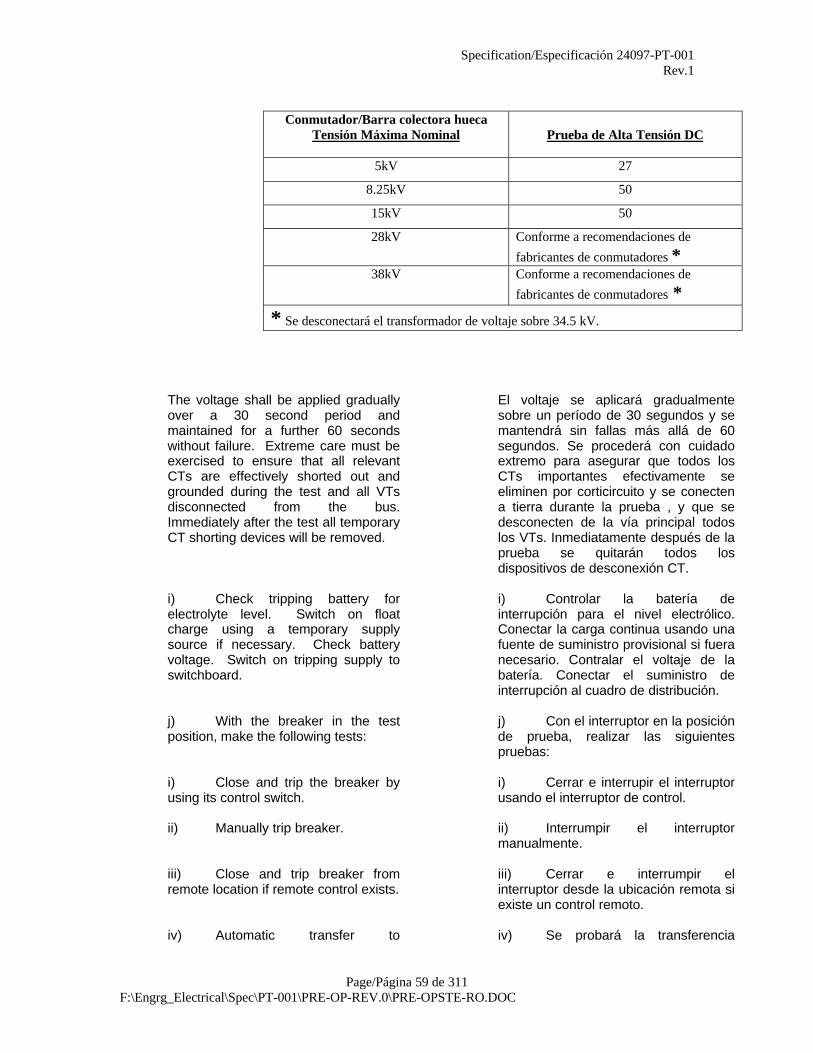
Specification/Especificación 24097-PT-001Rev.1
Page/Página 59 de 311F:\Engrg_Electrical\Spec\PT-001\PRE-OP-REV.0\PRE-OPSTE-RO.DOC
Conmutador/Barra colectora huecaTensión Máxima Nominal Prueba de Alta Tensión DC
5kV 27
8.25kV 50
15kV 50
28kV Conforme a recomendaciones de
fabricantes de conmutadores *38kV Conforme a recomendaciones de
fabricantes de conmutadores ** Se desconectará el transformador de voltaje sobre 34.5 kV.
The voltage shall be applied graduallyover a 30 second period andmaintained for a further 60 secondswithout failure. Extreme care must beexercised to ensure that all relevantCTs are effectively shorted out andgrounded during the test and all VTsdisconnected from the bus.Immediately after the test all temporaryCT shorting devices will be removed.
El voltaje se aplicará gradualmentesobre un período de 30 segundos y semantendrá sin fallas más allá de 60segundos. Se procederá con cuidadoextremo para asegurar que todos losCTs importantes efectivamente seeliminen por corticircuito y se conectena tierra durante la prueba , y que sedesconecten de la vía principal todoslos VTs. Inmediatamente después de laprueba se quitarán todos losdispositivos de desconexión CT.
i) Check tripping battery forelectrolyte level. Switch on floatcharge using a temporary supplysource if necessary. Check batteryvoltage. Switch on tripping supply toswitchboard.
i) Controlar la batería deinterrupción para el nivel electrólico.Conectar la carga continua usando unafuente de suministro provisional si fueranecesario. Contralar el voltaje de labatería. Conectar el suministro deinterrupción al cuadro de distribución.
j) With the breaker in the testposition, make the following tests:
j) Con el interruptor en la posiciónde prueba, realizar las siguientespruebas:
i) Close and trip the breaker byusing its control switch.
i) Cerrar e interrupir el interruptorusando el interruptor de control.
ii) Manually trip breaker. ii) Interrumpir el interruptormanualmente.
iii) Close and trip breaker fromremote location if remote control exists.
iii) Cerrar e interrumpir elinterruptor desde la ubicación remota siexiste un control remoto.
iv) Automatic transfer to iv) Se probará la transferencia
Specification/Especificación 24097-PT-001Rev.1
Page/Página 60 de 311F:\Engrg_Electrical\Spec\PT-001\PRE-OP-REV.0\PRE-OPSTE-RO.DOC
secondary selective systems shall betested by simulated power failure andunder voltage conditions.
automática a sistemas selectivossecundarios mediante una falla deenergía simulada y condiciones bajovoltaje.
v) Check test and operate allother auxiliary devices.
v) Controlar la prueba y operartodos los demás dispositivos auxiliares.
k) Check that all potentialtransformer fuses and control fuses arethe correct size and are installed.
k) Verificar que todos los fusiblesde transformadores potenciales yfusibles de control sean del tamañocorrecto y estén instalados.
l) Check main panel labelsagainst installed cables and confirmthat each panel is connected to thecorrect destination.
l) Controlar los rótulos del panelprincipal contra los cables instalados yconfirmar que cada panel estéconectado al destino correcto.
m) Pre-operational testing ofswitchgear also involves thepre-operational testing of the supplycircuit breaker and the interveningpower transformer, if any. Test andprove intertripping and pilot wireprotection. Feeder circuit breakersoutgoing from the switchgear are to betested in conjunction with theequipment connected to the feeder.
m) Las pruebas preoperacionalesdel conmutador también abarcan laspruebas preoperacionales del disyuntorautomático de suministro y eltransformador de energía interviniente,si existiera alguno. Probar y comprobarla interinterrupción y protección decables piloto. Los disyuntoresautomáticos de alimentación que salendel conmutador se deben probar juntocon el equipo conectado al alimentador.
12.1.3 Relays, Protective Devices andMetering
12.1.3 Relés, Dispositivos de Protección yMedición
Solid state metering and protective devices,shall be tested in accordance with themanufacturer’s requirements to include, but notlimited to:
La medición de estado sólido y los dispositivosde protección se probarán conforme a losrequerimientos del fabricante e incluirán, perono se limitarán a:
Power failure testingAnalog output testing
RTD measurement testing
Pruebas de falla de energíaPruebas de rendimiento analógicoPruebas de medición RTD
a) Check all relays for thefollowing:
a) Controlar todos los relés de lossiguientes:
i) Loose terminals, holding andlocking screws.
i) Terminales sueltas, tornillos de retención y cierre.
ii) Damage to coil, resistors,wiring, indicator targets and holdingdevices.
ii) Daños a bobinas, resistores,cables, señales indicadoras ydispositivos de retención.
iii) Foreign material in magnetgaps.
iii) Material extraño en aberturasmagnéticas.
Specification/Especificación 24097-PT-001Rev.1
Page/Página 61 de 311F:\Engrg_Electrical\Spec\PT-001\PRE-OP-REV.0\PRE-OPSTE-RO.DOC
iv) Any cause for sluggish action. iv) Cualquier causa de accióndébil.
v) Disc run-back time (should notexceed 12 seconds for full travel).
v) Tiempo de retroceso del disco(no debería exceder de 12 segundospor viaje completo)
b) All relays are to be set inaccordance with the relay settingtabulations furnished. Use themanufacturer's instruction booklets toset, adjust and calibrate protectiverelays.
b) Se deben colocar todos losrelés conforme a las tabulaciones decolocación de relés suministradas. Usarlos manuales de instrucciones delfabricante para colocar, ajustar ycalibrar los relés de protección.
c) The protective relays shallundergo the following checks:
c) Los relés de protección sesometerán a los siguientes controles:
i) Differential Relays - Test toverify the published differentialcharacteristics by checking theminimum operating current in eachrestraint coil.
i) Relés Diferenciales – Pruebapara verificar las característicasdiferenciales publicadas mediante elcontrol de la corriente en operaciónmínima en cada bobina retardatoria.
ii) Undervoltage Relays - Checkfor pickup and dropout values, timecharacteristics and any operationalfunction specified.
ii) Relés de Mínima Tensión –Controlar los valores de puesta entrabajo y paso al reposo, característicasde tiempo y cualquier funciónoperacional especificada.
iii) Directional Elements - Checkaction of relay with voltage and current.Check with high current and minimumvoltage required to cause effectiveclosing. In applying time settings to adirectional overcurrent relay, arrangethe test to include the time of both thedirectional and overcurrent elements.
iii) Elementos Direccionales –Controlar la acción del relé con lacorriente y la tensión. Controlar concorriente alta y tensión mínimanecesarias para un cierre efectivo. Alaplicar graduación de tiempos a un relépara sentido de sobrecorriente, arreglarla prueba para incluir el tiempo de loselementos direccionales y desobrecorriente.
iv) Instantaneous OvercurrentRelays and Elements - Checkminimum pickup current and response.
iv) Relés de sobrecorriente deacción instantánea y Elementos –Controlar la intensidad mínima deexcitación y respuestas.
v) Time Overcurrent Relays andElements - Check pickup current andoperating time at the specified currentvalues, at two points minimum. Maketest with relay isolated, also withcurrent transformers, meters, and otherburdens in the circuit, and note anysignificant differences.
v) Relés temporizado desobrecorriente y Elementos – Controlarcorriente de excitación magnética ytiempo de operación a valoresespecificados de corriente, en dospuntos mínimos. Realizar prueba con elrelé aislado, también con lostransformadores de corriente,medidores, y otras cargas en el circuito,y anotar diferencias significativas.
Specification/Especificación 24097-PT-001Rev.1
Page/Página 62 de 311F:\Engrg_Electrical\Spec\PT-001\PRE-OP-REV.0\PRE-OPSTE-RO.DOC
vi) Primary injection testing shallbe carried out on all protective relaysand each relay shall be proved tooperate in accordance with themanufacturer’s data and in line with therequirements of the system protected.A minimum of two tests, each atdifferent ratings, is required.
vi) La prueba de inyecciónprimaria se llevará a cabo en todos losrelés de protección y se probará quecada relé funciona conforme a los datosdel fabricante y en serie conforme a losrequerimientos del sistema protegido.Se requiere un mínimo de dos pruebas,cada una a un valor diferente.
Where the required primary injectioncurrent exceeds the rating of the testset then multiple primary turns on theCT may be employed for the test.Secondary injection tests may beapproved in special circumstances.
Donde la corriente de inyecciónprimaria requerida excede el valor de laprueba, entonces se pueden emplearespiras primarias múltiples en el CTpara la prueba. Las pruebas deinyección secundarias se puedenaprobar bajo circunstancias especiales.
vii) The testing shall includevoltage operated relays where avariable test voltage shall be applied.These shall include undervoltagerelays.
vii) Las pruebas incluirán relésaccionados por voltaje donde seaplicará un voltaje regulable parapruebas. Estos incluirán relés de voltajemínimo.
d) The relay test equipment shallinclude a variable source of sinusoidalcurrent, a variable source of sinusoidalvoltage, a timer, ammeters andvoltmeters to read both ac and dc, anda switching arrangement to permit testvoltage or current to be applied at thesame instant that the timer is started.In this way the time required for thecontacts to close after operating powerhas been applied can be determinedand adjusted when needed.
d) El equipo de pruebas para relésincluirá una fuente variable de corrientesinusoidal, una fuente variable devoltaje sinusoidal, un cronómetro,amperímetros y voltímetros para leercorriente alterna y corriente directa, yun conmutador que permita laaplicación de voltaje o corriente para laprueba en el mismo instante que seenciende el cronómetro. De estamanera se puede determinar y ajustarcuando sea necesario el tiemporequerido para que cierren loscontactos después de que se haaplicado potencia de servicio.
e) CT ratio, burden, polarity anddc resistance shall be checked againstthe respective drawings.
e) La relación CT, carga,polaridad y resistencia dc secontrolarán contra los planosrespectivos.
f) Check labels fixed near eachinstrument, or protective relay forcorrect data.
f) Controlar los rótulos cerca decada insturmento o relé de protección,para corroborar datos correctos.
g) The correct operation andcalibration of panel meters, includingwatt hour meters, shall be establishedusing appropriate voltage and currentinjection methods.
g) La operación y calibracióncorrectas de los medidores de panel,incluyendo contadores de vatio-hora, seestablecerán usando los métodos deinyección de voltaje y corrienteapropiados.
h) Out of calibration units shall be h) Las unidades fuera de calibre

Specification/Especificación 24097-PT-001Rev.1
Page/Página 63 de 311F:\Engrg_Electrical\Spec\PT-001\PRE-OP-REV.0\PRE-OPSTE-RO.DOC
returned to the Vendor for recalibration. se devolverán al Proveedor para que serecalibren.
12.1.4 Motor Control Centers 12.1.4 Centros de Control Motriz
a) Tests as described in Paragraph12.1.3.
a) Pruebas como se describen en elPárrafo 12.1.3.
b) For each starter module: b) Para cada módulo de arranque:
i) Check alignment and operationof main isolating switches and correctadjustment where necessary.
i) Controlar la alineación yoperación de los interruptoresprincipales de aislamiento y corregir losajustes donde sea necesario.
iii) Check phase rotation of MCCbus.
ii) Controlar la sucesión de fasesde la barra colectora MCC.
iii) Check polarity of all currentand potential transformers, transformersize and ratios, and continuity ofsecondary circuit.
iii) Controlar la polaridad de todoslos transformadores de corriente ytensión, relación y tamaño detransformadores, y continuidad decircuitos secundarios.
iv) Functionally check all controlpower circuits.
iv) Controlar funcionalmente todoslos circuitos de energía de control.
v) Set all solid state trip devicesand timers according to the SiteManager's instructions.
v) Colocar todos los cronómetrosy dispositivos de interrupción de estadosólido conforme a las instrucciones delGerente del Sitio.
vi) Functionally test and checksafety interlocks and the open andclose operations of each mechanicaland electrically operated circuitbreaker.
vi) Probar funcionalmente ycontrolar los interbloqueos de seguridady las operaciones de cierre y aberturade los disyuntores automáticosoperados mecánica y eléctricamente.
vii) Functionally check propertripping of each starter from allassociated relays by applyingappropriate test currents and/orvoltages to the sensing circuits.
vii) Controlar funcionalmente lainterrupción adecuada de cadaarrancador de todos los relés asociadosmediante la aplicación de corriente y/ovoltajes de prueba apropiados a loscircuitos sensibles.
viii) Check overload heaters,power, and control fuses for size andrating.
viii) Controlar resistencias decaldeo de sobreintensidad, energía yfusibles de control de acuerdo a sutamaño y clasificación.
ix) Check arc boxes and replace ifbroken.
ix) Controlar cajas de arco yreemplazar si hubiera rotas.
x) Check tightness of allconnections, particu-larly connectionsto the overload heaters.
x) Controlar ajuste de todas lasconexiones, particularmente lasconexiones de las resistencias de
Specification/Especificación 24097-PT-001Rev.1
Page/Página 64 de 311F:\Engrg_Electrical\Spec\PT-001\PRE-OP-REV.0\PRE-OPSTE-RO.DOC
caldeo de sobreintensidad.
xi) Set all protective relays in accordancewith drawings. Set motor overload relays tomotor full load current. Check motor overloadrelay heater rating or RTD operatingresistance.
xi) Colocar todos los relésprotectores conforme a los planos.Colocar los relés de sobreintensidadmotriz en corriente motriz de cargacompleta. Controlar el valor de laresistencia del relé de sobreintensidadmotriz o la resistencia operativa RTD.
xii) Check contacts and adjust sothat all "make" at the same time.
xii) Controlar contactos y ajustespara que todos “coincidan” a la vez.
xiii) Check meter and relay systemcontinuity.
xiii) Controlar la continuidad delsistema de relés y medición.
xiv) Check continuity of controlsystems. Refer to wiring diagrams andoperate with actual connections.
xiv) Controlar la continuidad de lossistemas de control. Referirse a losdiagramas de cables y operar con lasconexiones reales.
xv) If the equipment is theoil-immersed type, check for the propertype of oil used. Check to make surethat the oil tanks are not damaged orleaking.
xv) Si el equipo es en baño deaceite, controlar para el tipo apropiadode aceite usado. Controlar paraasegurar que los tanques de aceite noestán dañados ni tienen pérdidas.
c) All starters shall undergo amegger test. All equipment fromincoming to outgoing cable must havea resistance of at least 1,000 ohms perrated volt with a minimum allowable forany starter of l megohm regardless ofrated voltage.
c) Todos los arrancadores estaránsometidos a una prueba de megger.Todo el equipo desde cables entranteshasta cables salientes deben tener unaresistencia de por lo menos 1.000ohmios por voltio normal con un mínimoadmisible para cualquier arrancador de1 megaohmio al margen del voltajenominal.
d) Functionally check motoroverload units by primary injection, orsecondary injection if CTs are fitted.Trip times shall be monitored andchecked to verify that they are inaccordance with manufacturer'stolerances.
d) Controlar funcionalmente lasunidades de sobrecarga motrizmediante inyección primaria, oinyección secundaria si se haninstalado CTs. Se controlarán yverificarán los tiempos de interrupciónpara asegurar que cumplen con lospermisos del fabricante.
e) Check motor nameplate datawith motor starter nameplates andcomponent ratings, and verifycompatibility.
e) Controlar los datos de la placade identificación con la identificación delarranque motriz y los valores de loscomponentes, y verificar lacompatibilidad.
f) Operate the starter for properopening and closing from both remoteand local stations.
f) Operar el arranque para suabertura y cierre apropiados desdeestaciones locales y remotas.
Specification/Especificación 24097-PT-001Rev.1
Page/Página 65 de 311F:\Engrg_Electrical\Spec\PT-001\PRE-OP-REV.0\PRE-OPSTE-RO.DOC
g) Check main panel labelsagainst installed cables and confirmeach drive connected to correct starter.
g) Controlar los rótulos del panelprincipal contra los cables instalados yconfirmar que cada mecanismo estéconctado al arranque correcto.
h) A dc hi-pot test of eachmedium voltage motor control centerbus shall be performed. The voltage(rated volts x 2 plus 2 kV) shall beapplied gradually and maintained for afurther 60 second period withoutfailure. Busbars failing this will requireremoval and cleaning of insulation.
h) Se ejecutará una prueba dehipervoltaje dc de cada barra colectoradel centro de control motriz de voltajemedio. El voltaje (voltios normales x 2más 2 kV) se aplicará gradualmente porun período de más de 60 segundos sinfallas. Se necesitará quitar las barrascolectoras que fallen y limpiarlas deaislamiento.
i) Check all cabinet penetrationsfor rust.
i) Controlar el óxido en todas lasentradas.
j) Check phasing of incomingand outgoing circuits to ensurecontinuity of each phase.
j) Controlar las fases de circuitosentrantes y salientes para asegurar lacontinuidad de cada fase.
k) Pre-operational testing of themotor control center involves also thepre-operational testing of the supplycircuit breaker in the switchgear.
k) Las pruebas preoperacionalesdel centro de control motriz abarcatambién las pruebas preoperacionalesdel interruptor automático de suministroen el conmutador.
12.1.5 Transformers 12.1.5 Transformadores
a) Carry out the following physicalinspection and tests:
a) Ejecutar las siguientes inspeccionesfisicas y pruebas:
i) Inspect bushings for chips orcracks.
i) Inspeccionar el pasanteaislante para localizar rajaduras opicaduras.
ii) Check for any damage to tank,fins, and the like.
ii) Verificar si los tanques, aletas yelementos similares están dañados.
iii) Check cooling fan mountingsand general condition.
iii) Verificar las acopladuras y lascondiciones generales de losventiladores de enfriamiento.
iv) Check cooling fan controlpanel.
iv) Verificar el tablero de controlesde los ventiladores de enfriamiento.
v) Check tap changer for propermovement.
v) Verificar que el cambiador detoma tiene el movimiento apropiado.
vi) Check operation oftemperature and pressure indicatorsand trip/alarm relays.
vi) Verificar la operación de losindicadores de presión y temperatura ylos relés desconectadores/alarmas.
vii) Inspect all gaskets and fittingsfor oil leakage.
vii) Verificar pérdida de aceite entodas la juntas y adaptadores.
Specification/Especificación 24097-PT-001Rev.1
Page/Página 66 de 311F:\Engrg_Electrical\Spec\PT-001\PRE-OP-REV.0\PRE-OPSTE-RO.DOC
viii) Check oil level and gaspressure in sealed transformers.
viii) Verificar el nivel de aceite y lapresión de gas en los transformadoressellados.
ix) Check nameplate data againsttransformer data sheets and single linediagrams.
ix) Verificar los datos de la placade características con las hojas dedatos del transformador y losdiagramas de línea simple.
b) Perform dielectric strength tests on allinsulating liquids. If liquid has beenstored for more than six months, awater content test is required. Allsampling and tests shall be inaccordance with ASTM D877. The testsamples must withstand a minimum of30 kV and have a water content of lessthan 35 mg/kg. Liquids which fail thesetests shall be refurbished asapplicable.
b) Realizar pruebas de resistenciadieléctrica en todos los líquidosinsulantes. Si el líquido ha estadoguardado por más de seis meses, serequiere una prueba de contenido deagua. Todas las muestras y las pruebasse deberan realizar de acuerdo a ASTMD877. Las muestras de pruebas debensoportar un mínimo de 30 kV y debentener un contenido de agua de menosde 35 mg/kg. Los líquidos que no pasenestas pruebas deberán serreconstruídos como corresponda.
Ensure primary, secondary and neutralcables are disconnected and then carryout megger tests using 5 kV megger.
Asegurar que los cables primarios,secundarios y neutrales esténdesconectados y luego realizar pruebasde megger usando un magahómetro de5 kV.
c) Factory sealed, liquid-submerged coilsthat satisfy the strength test can be putin service if insulation test exceeds 6Megohms between windings andground and other windings. A check ofmegger readings againstmanufacturer's test certificate shall bemade.
c) Las bobinas que están sumergidas enlíquido, empaquetadas en fábrica, y quesatisfacen las pruebas de resistencia sepodrán poner en servicio si la prueba deinsulación supera los 6 Meghómetrosentre bobinados y la toma de tierrra yotros devanados. Se realizará unaverificación de las lecturas de meggercontra los certificados de las pruebasrealizadas por el fabricante.
Liquid-submerged coils that fail thestrength tests and coils shipped withoutinsulating liquid must undergoout-of-liquid "megger" tests. Themegger readings should be in excessof 1 Megohm per rated kilovolt of thecoil.
Las bobinas sumergidas en líquido queno pasen las pruebas de resistencia ylas bobinas que se enviaron sin ellíquido insulante deberán pasar laspruebas de “megger” fuera del líquido.Las lecturas del megger deberánsuperar 1 Meghómetro por kilovoltioestimado de bobina.
If the windings fail the megger test,they shall be dried out and retested.
Si los bobinados no pasan las pruebasde megger, se deberán secar y sevolverán a probar.
d) The drying should be continued untilconsistently high resistance values are
d) El secado será continuo hasta que sehayan obtenido valores de alta

Specification/Especificación 24097-PT-001Rev.1
Page/Página 67 de 311F:\Engrg_Electrical\Spec\PT-001\PRE-OP-REV.0\PRE-OPSTE-RO.DOC
obtained for at least four consecutivemeasurements covering a period of atleast 16 hours of the drying time.
resistencia en por lo menos cuatromediciones consecutivas que cubren unperíodo de por lo menos 16 horas detiempo de secado.
If the internal heat method is used fordrying, it shall be done as follows:
Si se utiliza el método de calor internopara el secado, se realizará de lasiguiente manera:
i) Short circuit secondarywindings.
i) Bobinas secundarias de cortocircuito.
ii) Impress voltage of 0.5-1.5%rated voltage on primary windings.
ii) Establecer voltaje de 05-1.5%de voltaje estimado en bobinas primarias.
iii) Limit drying current to one-fifththe normal winding current.
iii) Limitar la corriente de secado aun-quinto de la corriente normal de bobinado.
iv) Maintain coil temperature a60oC to 70oC by adjusting coil current.
iv) Mantener la temperatura de labobina de 60oC a 70oC haciendo un ajuste enla corriente de la bobina.
v) The megger test is to be madeat a coil temperature of 60oC to 70oC.
v) La prueba de megger sedeberá realizar a una temperatura de bobina de60oC a 70oC.
e) Check phasing of primary andsecondary circuits to ensure continuityof phases across the transformer.
e) Verificar la sincronización de loscircuitos primarios y secundarios paraasegurar una continuidad de fases en eltransformador.
12.1.6 Motors 12.1.6 Motores
All motors shall be inspected, tested andprepared for energization in accordance withmanufacturer's instructions and with thecoordination of a representative of theManager. This procedure shall include, but notbe limited to, the following:
Todos los motores serán inspeccionados,probados y preparados para la energización deacuerdo a las instrucciones del fabricante yconjuntamente con la coordinación con unrepresentante del Gerente. Este procedimientoincluirá pero no estará limitado a lo siguiente:
a) Check for correct clearances,alignment and lubrication. If required,lubricate in accordance with themanufacturer's instructions. Specialtests as suggested by manufacturer,such as gap spacing and pedestalalignment, shall be made whereapplicable.
a) Verificar los gálibos correctos,alineamiento y lubricación. Si esnecesario, lubricar de acuerdo a lasinstrucciones del fabricante. Pruebasespeciales sugeridas por el fabricante,tales como el espaciamiento deaberturas y la alineación de pedestales,serán realizadas donde corresponda.
b) For motor ratings of 110 kW (150 hp)and below a dielectric absorption testshall be made on the motor windings.The thirty/sixty (30/60) second ratioshall be determined. Ratio readings ofless than 1.4 shall be investigated.
b) Para motores de 110 kW (150 hp) y pordebajo de una prueba de histéresisdieléctrica será realizada en el bobinadode motores. Se determinará la segundaproporción de treinta/sesenta (30/60).Las lecturas de las proporciones demenos de 1.4 serán investigadas.

Specification/Especificación 24097-PT-001Rev.1
Page/Página 68 de 311F:\Engrg_Electrical\Spec\PT-001\PRE-OP-REV.0\PRE-OPSTE-RO.DOC
c) Pedestal bearing insulation shall betested per manufacturer's instructions.
c) La insulación del soporte de caballeteserá probada de acuerdo a lasinstrucciones del fabricante.
d) For motor rated 4000 volts and above,an over-potential test between thewinding and ground shall be carriedout. This shall be made at 80 percentof twice rated voltage plus 1,000 V.
d) Se ejecutará una prueba sobrepotencialidades entre el bobinado y latoma a tierra en los motores con unpromedio de 4000 y más voltios. Estose realizará a 80 por ciento de unvoltage tasado dos veces más 1.000 V.
e) A rotation test shall be made to ensureproper shaft direction.
e) Una prueba de rotación será ejecutadapara asegurar la dirección adecuada deleje.
f) A motor vibration test shall be carriedout with motor uncoupled, and thenwith motor coupled. Refer tomanufacturer's instructions formaximum allowable amplitudes.
f) Una prueba para la vibración del motorserá ejecutada con el motor sin acoplar,y luego con el motor acoplado. Véaselas instrucciones del fabricante para lasextensiones máximas permitidas.
g) All RTDs shall be checked for properconnection and for wiring continuity.
g) Se verificará que todos los RTDs tienenla conexion apropiada y continuidad decableaje.
h) Record nameplate data and comparewith motor data sheet entries.
h) Registrar los datos de la placapublicitaria y compararlos con aquellosde las hojas de datos del motor.
i) On totally enclosed machines opendrain hole to check for moisture.
i) Abrir un agujero de drenaje paraverificar humedad en aquellasmáquinas completamente cerradas.
j) Measure insulation resistance using a1kV megger for motors less than 600Vand a 5kV megger for motors greaterthan 600V. Apply test for one minute.The megger readings should not besubstantially lower than values shownon manufacturer's test certificates. Ifcertificates are not available thefollowing shall be considered asminimum acceptable values:
j) Medir la resistencia de la insulaciónusando un megger de 1kV paramotores con menos de 600V y unmegger de 5kV para motores con másde 600V. Ejecute la prueba durante unminuto. Las lecturas de megger nodeberán ser significativamentemenores a los valores indicados en loscertificados de pruebas de losfabricantes. Si los certificados no seencuentran disponibles, lo siguienteserá considerado como los valoresmínimos aceptables:
Volts Megohms Voltios Megaohmios460 1.5 460 1.54000 4.3 4000 4.36600 6.0 6600 6.013.2kV 16.0 13.2kV 16.0
Motors that fail the insulationresistance must be dried out. Coils
Se deberán secar los motores que nopasan la prueba de la resistencia del

Specification/Especificación 24097-PT-001Rev.1
Page/Página 69 de 311F:\Engrg_Electrical\Spec\PT-001\PRE-OP-REV.0\PRE-OPSTE-RO.DOC
must not exceed 80°C when measuredby thermometer or 90°C whenmeasured by the resistance method.The rate of temperature rise shall belimited to 5°C per hour (ref.IEEE-3-1974).
aislamiento. Las bobinas no deberánexceder 80°C cuando se miden contermómetro o 90°C cuando se midencon el método de resistencia. Elpromedio de aumento de temperaturaestará limitado a 5°C por hora. (ref.IEEE-#-1974).
Drying should be continued until fourconsistently high resistance values areobtained. Readings should be taken atfour hour intervals.
Se continuará el secado hasta que sepuedan obtener cuatro valoresconsistentes de alta resistencia. Sedeberán tomar las lecturas a intervalosde cuatro horas.
k) Confirm oil levels as applicable. k) Confirmar los niveles de aceite comocorresponda.
l) Motors 37.5kW (50 hp) and larger shallbe uncoupled and run until motortemperature stabilizes (usually 2-3hours) or as specified in vendormanuals. Check and record motortemperature, speed, current, rotation,and vibration.
l) Los motores de 37.5 kW (50 hp) y másgrandes serán desacoplados yfuncionarán hasta que la temperaturadel motor se estabilice (por lo generalde 2 a 3 horas) o como se especifiqueen los manuales del proveedor. Verificary registrar la temperatura, la velocidad,la corriente, la rotación y la vibración delmotor.
The frequency of large motor startsshall be maintained within theallowable limits specified bymanufacturer.
La frecuencia de arranque de grandesmotores será mantenida dentro de loslímites permitidos especificados por elfabricante.
m) Before energizing slip ring motorscheck rotor resistance value andrecord the connection layout of theresistors. Check that sequence andtiming of rotor resistance contactorscorrespond to the drawings and thatrotor resistance is successivelyreduced.
m) Antes de energizar los anillos rozantesde los motores, verificar el valor deresistencia del rotor y registrar eldiagrama de conexión de los reostatos.Verificar que la secuencia y afino deencendido de los contactores deresistencia de los rotores correspondena los dibujos y que la resistencia delrotor sea reducida exitosamente.
n) On motors fitted with condensationheaters and winding temperaturedetectors measure the resistance ofthe winding temperature detectors andmegger the heaters.
n) Medir la resistencia de los detectores detemperatura y megger los radiadores delos motores que tienen radiadores decondensación y detectores detemperatura de bobinados instalados.
12.1.7 Cables 12.1.7 Cables
a) All wire and cable shall be visuallyinspected for faulty insulation prior toinstallation. After installation of wireand termination devices is complete,but before connecting to equipment, allwires and cable shall be tested for
a) Se inspeccionarán visualmente todoslos alambres y los cables para verificarsi hay aislamiento defectuoso antes desu instalación. Después que losalambre se instalaron y los dispositivosde terminación se han completado, pero
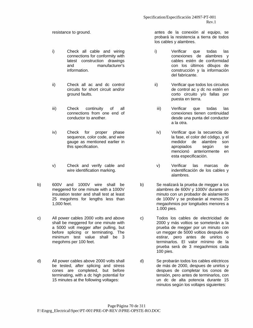
Specification/Especificación 24097-PT-001Rev.1
Page/Página 70 de 311F:\Engrg_Electrical\Spec\PT-001\PRE-OP-REV.0\PRE-OPSTE-RO.DOC
resistance to ground. antes de la conexión al equipo, seprobará la resistencia a tierra de todoslos cables y alambres.
i) Check all cable and wiringconnections for conformity withlatest construction drawingsand manufacturer'sinformation.
i) Verificar que todas lasconexiones de alambres ycables estén de conformidadcon los últimos dibujos deconstrucción y la informacióndel fabricante.
ii) Check all ac and dc controlcircuits for short circuit and/orground faults.
ii) Verificar que todos los circuitosde control ac y dc no estén encorto circuito y/o fallas porpuesta en tierra.
iii) Check continuity of allconnections from one end ofconductor to another.
iii) Verificar que todas lasconexiones tienen continuidaddesde una punta del conductora la otra.
iv) Check for proper phasesequence, color code, and wiregauge as mentioned earlier inthis specification.
iv) Verificar que la secuencia dela fase, el color del código, y elmedidor de alambre sonapropiados según semencionó anteriormente enesta especificación.
v) Check and verify cable andwire identification marking.
v) Verificar las marcas deindentificación de los cables yalambres.
b) 600V and 1000V wire shall bemeggered for one minute with a 1000Vinsulation tester and shall test at least25 megohms for lengths less than1,000 feet.
b) Se realizará la prueba de megger a losalambres de 600V y 1000V durante unminuto con un probador de aislamientode 1000V y se probarán al menos 25megaohmios por longitudes menores a1.000 pies.
c) All power cables 2000 volts and aboveshall be meggered for one minute witha 5000 volt megger after pulling, butbefore splicing or terminating. Theminimum test value shall be 3megohms per 100 feet.
c) Todos los cables de electricidad de2000 y más voltios se someterán a laprueba de megger por un minuto conun megger de 5000 voltios después deestirar, pero antes de unirlos oterminarlos. El valor mínimo de laprueba será de 3 megaohmios cada100 pies.
d) All power cables above 2000 volts shallbe tested, after splicing and stresscones are completed, but beforeterminating, with a dc high potential for15 minutes at the following voltages:
d) Se probarán todos los cables eléctricosde más de 2000, despues de unirlos ydespues de completar los conos detensión, pero antes de terminarlos, conun dc de alta potencia durante 15minutos según los voltajes siguientes:
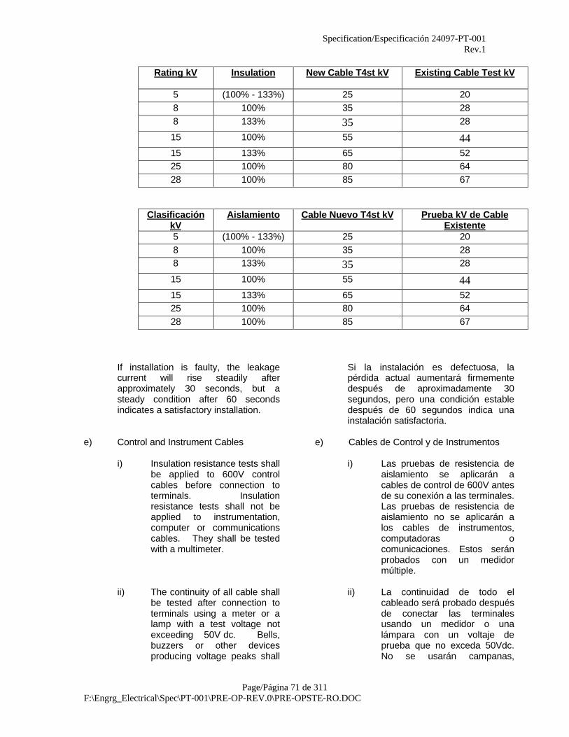
Specification/Especificación 24097-PT-001Rev.1
Page/Página 71 de 311F:\Engrg_Electrical\Spec\PT-001\PRE-OP-REV.0\PRE-OPSTE-RO.DOC
Rating kV Insulation New Cable T4st kV Existing Cable Test kV
5 (100% - 133%) 25 208 100% 35 288 133% 35 28
15 100% 55 4415 133% 65 5225 100% 80 6428 100% 85 67
ClasificaciónkV
Aislamiento Cable Nuevo T4st kV Prueba kV de CableExistente
5 (100% - 133%) 25 208 100% 35 288 133% 35 28
15 100% 55 4415 133% 65 5225 100% 80 6428 100% 85 67
If installation is faulty, the leakagecurrent will rise steadily afterapproximately 30 seconds, but asteady condition after 60 secondsindicates a satisfactory installation.
Si la instalación es defectuosa, lapérdida actual aumentará firmementedespués de aproximadamente 30segundos, pero una condición establedespués de 60 segundos indica unainstalación satisfactoria.
e) Control and Instrument Cables e) Cables de Control y de Instrumentos
i) Insulation resistance tests shallbe applied to 600V controlcables before connection toterminals. Insulationresistance tests shall not beapplied to instrumentation,computer or communicationscables. They shall be testedwith a multimeter.
i) Las pruebas de resistencia deaislamiento se aplicarán acables de control de 600V antesde su conexión a las terminales.Las pruebas de resistencia deaislamiento no se aplicarán alos cables de instrumentos,computadoras ocomunicaciones. Estos seránprobados con un medidormúltiple.
ii) The continuity of all cable shallbe tested after connection toterminals using a meter or alamp with a test voltage notexceeding 50V dc. Bells,buzzers or other devicesproducing voltage peaks shall
ii) La continuidad de todo elcableado será probado despuésde conectar las terminalesusando un medidor o unalámpara con un voltaje deprueba que no exceda 50Vdc.No se usarán campanas,
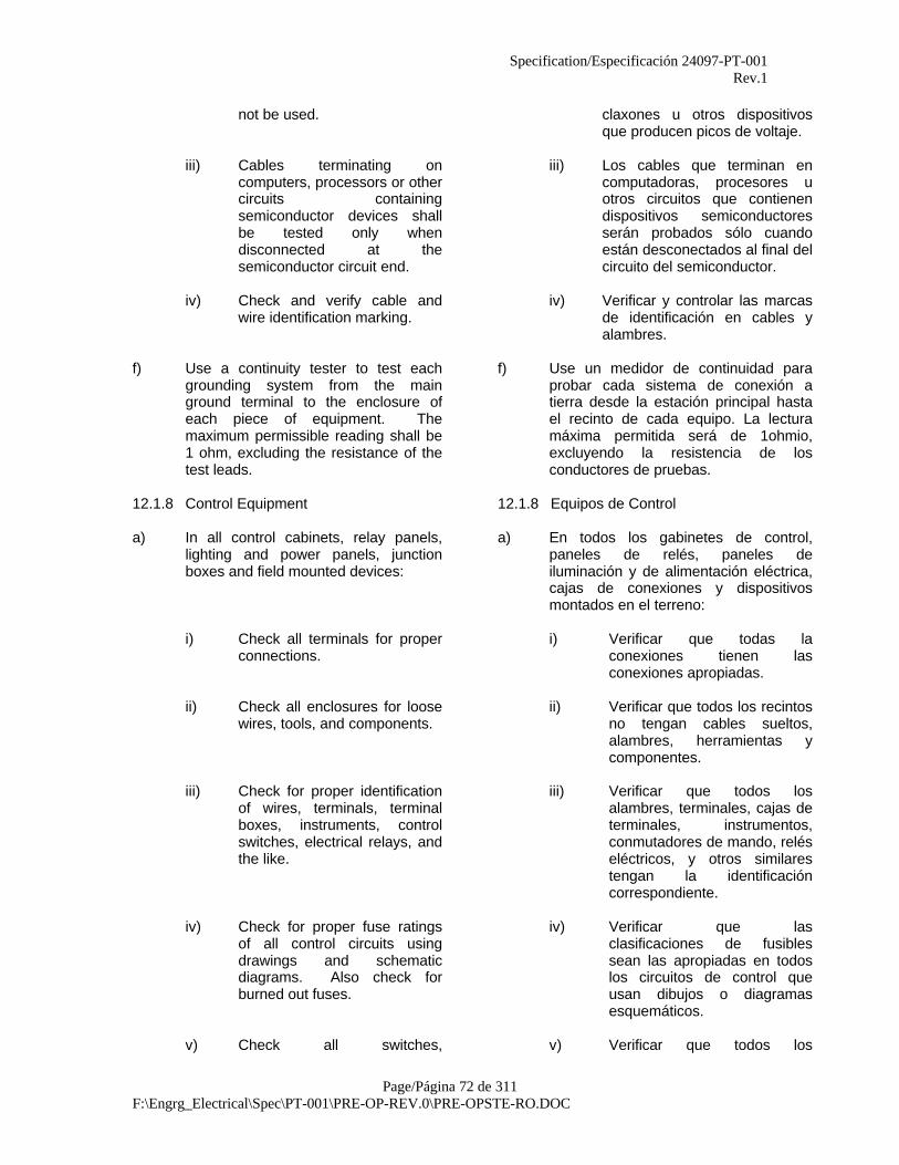
Specification/Especificación 24097-PT-001Rev.1
Page/Página 72 de 311F:\Engrg_Electrical\Spec\PT-001\PRE-OP-REV.0\PRE-OPSTE-RO.DOC
not be used. claxones u otros dispositivosque producen picos de voltaje.
iii) Cables terminating oncomputers, processors or othercircuits containingsemiconductor devices shallbe tested only whendisconnected at thesemiconductor circuit end.
iii) Los cables que terminan encomputadoras, procesores uotros circuitos que contienendispositivos semiconductoresserán probados sólo cuandoestán desconectados al final delcircuito del semiconductor.
iv) Check and verify cable andwire identification marking.
iv) Verificar y controlar las marcasde identificación en cables yalambres.
f) Use a continuity tester to test eachgrounding system from the mainground terminal to the enclosure ofeach piece of equipment. Themaximum permissible reading shall be1 ohm, excluding the resistance of thetest leads.
f) Use un medidor de continuidad paraprobar cada sistema de conexión atierra desde la estación principal hastael recinto de cada equipo. La lecturamáxima permitida será de 1ohmio,excluyendo la resistencia de losconductores de pruebas.
12.1.8 Control Equipment 12.1.8 Equipos de Control
a) In all control cabinets, relay panels,lighting and power panels, junctionboxes and field mounted devices:
a) En todos los gabinetes de control,paneles de relés, paneles deiluminación y de alimentación eléctrica,cajas de conexiones y dispositivosmontados en el terreno:
i) Check all terminals for properconnections.
i) Verificar que todas laconexiones tienen lasconexiones apropiadas.
ii) Check all enclosures for loosewires, tools, and components.
ii) Verificar que todos los recintosno tengan cables sueltos,alambres, herramientas ycomponentes.
iii) Check for proper identificationof wires, terminals, terminalboxes, instruments, controlswitches, electrical relays, andthe like.
iii) Verificar que todos losalambres, terminales, cajas determinales, instrumentos,conmutadores de mando, reléseléctricos, y otros similarestengan la identificacióncorrespondiente.
iv) Check for proper fuse ratingsof all control circuits usingdrawings and schematicdiagrams. Also check forburned out fuses.
iv) Verificar que lasclasificaciones de fusiblessean las apropiadas en todoslos circuitos de control queusan dibujos o diagramasesquemáticos.
v) Check all switches, v) Verificar que todos los

Specification/Especificación 24097-PT-001Rev.1
Page/Página 73 de 311F:\Engrg_Electrical\Spec\PT-001\PRE-OP-REV.0\PRE-OPSTE-RO.DOC
pushbuttons for completenessof movement, installation,contacts, adjustment, ratingand labelling.
conmutadores y botonespulsadores estén totalmenteinstalados, en movimiento, encontacto, calibrados,clasificados y etiquetados.
vi) Verify that enclosures areequipped with drain andbreather fittings if specified andinspect all boxes for anymoisture collection.
vi) Verificar que todos los recintosestén equipados con losaccesorios de drenaje yrespiradero, si se haespecificado e inspeccionartodas las cajas para evitar lapresencia de humedad.
vii) Check for proper bundling ofwires.
vii) Verificar que todos losalambres estén envueltoscorrectamente
viii) Check all wires terminated forbeing free of grounds.
viii) Verificar que todos losalambres terminados esténlibres de sedimentos.
ix) Check for proper sequence ofconnections as per schematicdiagrams.
ix) Verificar que las conexionestienen la secuencia apropiadade acuerdo a los diagramasesquemáticos.
x) Check for proper grounding ofenclosures and ground, screenand drain wires in cables.
x) Verificar la puesta a tierrra delos cables en los recintos,pantallas y los hilos de retornopor tierra.
xi) Check for proper sealing ofconduit connections, cableglands, etc.
xi) Verificar que los conductos deconexión, los casquillos parapaso de cables, etc. esténsellados como corresponde.
xii) Check that all spareconductors are identified.
xii) Verificar que todos losconductores de repuesto esténidentificados.
xiii) Check cable polarities, cablesizes and cable types againstdrawings.
xiii) Verificar la polaridad de loscables, las medidas y los tiposde cables en los dibujos.
xiv) Check polarity of all staticdevices such as diodes.
xiv) Verificar la polaridad de todoslos dispositivos estáticos talescomo los diodos.
xv) Verify circuit cards and/ordrawings which are required tobe left in the enclosures.
xv) Verificar cuales son las tarjetasde circuito y/o los dibujos quese deben dejar en los recintos.
xvi) Check that all relay coils aresuitable for the designedoperating voltage and that the
xvi) Verificar que todas las bobinasde relés son las apropiadaspara el voltaje designado y que
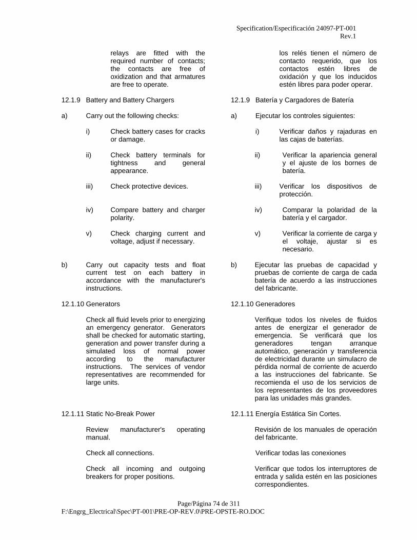
Specification/Especificación 24097-PT-001Rev.1
Page/Página 74 de 311F:\Engrg_Electrical\Spec\PT-001\PRE-OP-REV.0\PRE-OPSTE-RO.DOC
relays are fitted with therequired number of contacts;the contacts are free ofoxidization and that armaturesare free to operate.
los relés tienen el número decontacto requerido, que loscontactos estén libres deoxidación y que los inducidosestén libres para poder operar.
12.1.9 Battery and Battery Chargers 12.1.9 Batería y Cargadores de Batería
a) Carry out the following checks: a) Ejecutar los controles siguientes:
i) Check battery cases for cracksor damage.
i) Verificar daños y rajaduras enlas cajas de baterías.
ii) Check battery terminals fortightness and generalappearance.
ii) Verificar la apariencia generaly el ajuste de los bornes debatería.
iii) Check protective devices. iii) Verificar los dispositivos deprotección.
iv) Compare battery and chargerpolarity.
iv) Comparar la polaridad de labatería y el cargador.
v) Check charging current andvoltage, adjust if necessary.
v) Verificar la corriente de carga yel voltaje, ajustar si esnecesario.
b) Carry out capacity tests and floatcurrent test on each battery inaccordance with the manufacturer'sinstructions.
b) Ejecutar las pruebas de capacidad ypruebas de corriente de carga de cadabatería de acuerdo a las instruccionesdel fabricante.
12.1.10 Generators 12.1.10 Generadores
Check all fluid levels prior to energizingan emergency generator. Generatorsshall be checked for automatic starting,generation and power transfer during asimulated loss of normal poweraccording to the manufacturerinstructions. The services of vendorrepresentatives are recommended forlarge units.
Verifique todos los niveles de fluidosantes de energizar el generador deemergencia. Se verificará que losgeneradores tengan arranqueautomático, generación y transferenciade electricidad durante un simulacro depérdida normal de corriente de acuerdoa las instrucciones del fabricante. Serecomienda el uso de los servicios delos representantes de los proveedorespara las unidades más grandes.
12.1.11 Static No-Break Power 12.1.11 Energía Estática Sin Cortes.
Review manufacturer's operatingmanual.
Revisión de los manuales de operacióndel fabricante.
Check all connections. Verificar todas las conexiones
Check all incoming and outgoingbreakers for proper positions.
Verificar que todos los interruptores deentrada y salida estén en las posicionescorrespondientes.
Specification/Especificación 24097-PT-001Rev.1
Page/Página 75 de 311F:\Engrg_Electrical\Spec\PT-001\PRE-OP-REV.0\PRE-OPSTE-RO.DOC
Check battery charger ac inputvoltages.
Verificar el voltaje ac de tensión deentrada del cargador de batería.
Check output ac and dc voltages. Verificar los voltajes ac y dc de potenciagenerada.
The following tests should be performed inaccordance with the manufacturer'srecommendations before the units are put intoservice.
Las pruebas siguientes se deberán ejecutar deacuerdo a las recomendaciones del fabricanteantes de colocar a las unidades enfuncionamiento.
a) Synchronization of ac outputs,ac input and output.
a) Sincronización de potenciasgeneradas de ac, tensión deentrada de ac y su potenciagenerada.
b) No-Break, ac, dc. b) Ac, dc Sin Interrupciones.
c) Battery output voltage andcharger operation, during acinput failure.
c) Voltaje de potencia generadade batería de la operación delcargador durante la falla detensión de entrada ac.
12.1.12 Grounding 12.1.12 Puesta a Tierra.
The grounding system shall bechecked to ensure that all parts of steelstructures, motor frames, switch-gear,trays, conduits and other electricalequipment are grounded in accordancewith the drawings.
El sistema de puesta a tierra seráverificado para asegurarse que todaslas partes de las estructuras de acero,armazones de motores, conmutadoresde cambio, bandejas, conductos y otrosequipos eléctricos estén puestos a tierrade acuerdo a los dibujos.
With the use of ground testing meterdetermine the ground grid resistancesas specified on grounding drawings.
Determinar las resistencias de rejilla entierra como se especifica en los dibujosde puesta a tierra, usando el medidorde pruebas de puesta a tierra.
Check all grounding test bars andconnections.
Verificar la puesta a tierra de todas lasprobetas de pruebas y conexiones.
Check, separately if required, that thecontrol and computer systemgrounding systems are adequate andeffectively separated.
Verificar, de forma separada si esnecesario, que los sistemas de puesta atierra para el sistema de computadorasy de control sean adecuados yseparados con eficiencia.
After completion of individual groundtests, the overall grounding resistanceshall be measured and recorded in acertified formal report.
Después de completar las pruebasindividuales de puesta a tierra, laresistencia global de puesta a tierraserá medida y registrada en un informeformal certificado.
12.1.13 Lighting and Small Power Circuits 12.1.13 Iluminación y Circuitos de PocaPotencia

Specification/Especificación 24097-PT-001Rev.1
Page/Página 76 de 311F:\Engrg_Electrical\Spec\PT-001\PRE-OP-REV.0\PRE-OPSTE-RO.DOC
a) Carry out the following tests on thecircuits and equipment:
a) Ejecutar las pruebas siguientes en loscircuitos y equipos.
i) Test each individual circuit witha continuity tester to ascertainthat the wiring and connectionsare correct.
i) Probar los circuitosindividuales con un medidor decontinuidad para asegurarseque las conexiones y elalambrado están correctos.
ii) Check all power outlets forcorrect polarity.
ii) Verificar que todas las tomasde corriente tienen la polaridadcorrecta.
b) When all lighting system tests havebeen completed satisfactorily, thesystem shall be energized andfunctional tests shall be executed.Check that floodlights and all otherdirectional fittings direct light into thespecified areas.
b) Cuando todos los sistemas deiluminación se han completadosatisfactoriamente, el sistema seráenergizado y se ejecutarán pruebasfuncionales. Verificar que las luces deinundación y todos los otros accesoriosdireccionales dirigen la luz hacia lasareas especificadas.
12.1.14 Electrical Heat Tracing 12.1.14 Seguimiento de Calor Eléctrico
Carry out the following tests on thecircuits and equipment:
Ejecutar las pruebas siguientes en loscircuitos y equipos:
a) Check continuity a) Verificar continuidadb) Check insulation to ground b) Verificar el aislamiento a tierrac) Check inrush current readings c) Verificar lecturas de corrientes
de entradad) Check operation of
temperature controlsd) Verificar la operación de los
controles de temperatura.
12.1.15 Lightning Protection 12.1.15 Protección de Iluminación
a) Inspection and approval shallbe by the authority havingjurisdiction in the area.
a) La autoridad con jurisdicciónen esa área realizará lasinspecciones y aprobaciones.
b) A certificate of complianceissued by the authority havingjurisdiction shall be furnishedto Owner.
b) La autoridad con jurisdicciónemitirá un certificado decumplimiento y se lo entregaráal Propietario.
12.1.16 Adjustable Frequency Drives (AFDs) 12.1.16 Conductores Ajustables de Frecuencia(AFDs)
AFDs shall be tested in accordance with themanufacturer's recommendation to include, butnot limited to:
Se probarán los AFDs de acuerdo a lasrecomendaciones del fabricante para incluir,pero sin limitarse a:
i) verifying proper terminations i) control de las terminaciones apropiadas
ii) verifying proper supply/output voltages ii) control de los voltajes apropiados para

Specification/Especificación 24097-PT-001Rev.1
Page/Página 77 de 311F:\Engrg_Electrical\Spec\PT-001\PRE-OP-REV.0\PRE-OPSTE-RO.DOC
el suministro/generación de electricidad
iii) verifying proper input/output signalstrengths
iii) control de las potencias apropiadas delas señales de entradas y salidas
iv) verifying correct programming ofcontrol unit
iv) control de la programación correcta dela unidad de control.
v) verifying proper control output at 0,25,50, 75 and 100 percent
v) control de una generación de potenciaapropiada de 0,25, 50, 75 y 100 porciento.
12.1.17 Underground Conduits 12.1.17 Conductos Subterráneos
a) Before any section of conduitis covered with concrete orburied, each conduit shall betested for obstructions orflattening by drawing through amandrel of the proper size.
a) Antes que cualquier secciónde conducto se cubra conconcreto o se entierre, cadaconducto será probado paracontrolar obstrucciones oachatándose pasando por unmandril de tamaño apropiado.
b) Immediately after a conduitbank has been covered orencased with concrete andbefore initial set takes place,the proper mandrel shall againbe run through each conduit todetermine if any obstructionsor defects exist. Defects shallbe immediately corrected.
b) Inmediatamente después queun banco de conducto ha sidocubierto o recubiertos conconcreto y antes delasentamiento inicial, el mandrilapropiado se pasará por cadaconducto para determinar siexisten obstrucciones odefectos. Los defectos seráncorregidos inmediatamente.
c) Exposed ends of conduit shallbe sealed with plugs or capsafter testing to prevent theentrance of vermin, moistureand debris until the conduit isput into service or extended.
c) Las puntas expuestas de losconductos serán selladas contapones o tapas después deprobadas para prevenir laentrada de humedad, insectos ybasuras hasta que el conductose extienda o se ponga enfuncionamiento.
d) Conduit seals in classifiedareas shall not be poured untilcompletion of wire testing andrelease.
d) Los sellos de conductos enáreas clasificadas no secolocarán hasta que no sehayan completado y aprobadolas pruebas de alambrado.
13.0 INSTRUMENTATION 13.0 INSTRUMENTACION
Applicable inspections and tests to verifycontinuity, indication, containment, calibration,loop tests, adjustments, stroking, andfunctional operation and activation of controlsystems involving all instrumentation.Instrument calibration is performed by the
Las inspecciones y pruebas correspondientespara verificar la continuidad, indicación,embalaje, calibración, pruebas de circuito,ajustes, frecuencia, operación funcional yactivación de los sistemas de control queabarcan a toda la instrumentación. La
Specification/Especificación 24097-PT-001Rev.1
Page/Página 78 de 311F:\Engrg_Electrical\Spec\PT-001\PRE-OP-REV.0\PRE-OPSTE-RO.DOC
Contractor Construction personnel inaccordance with contract Specification24097-GJ-003 "General Specification forInstrument Installation, Calibration andTesting".
calibración de los instrumentos será ejecutadapor el personal de construcción del contratistade acuerdo con la especificación del contrato24097-GJ-003. “Especificación General para laInstalación, Calibración y Pruebas deInstrumentos.”
13.1 Procedures 13.1 Procedimientos
13.1.1 Criteria 13.1.1 Criterios.
a) Comparison shall be made ofinstruments versus data sheetsto check, as applicable,calibrated range, casepressure, materials ofconstruction, power supply, tagnumbers, etc.
a) Se compararán losinstrumentos contra las hojasde datos para verificar, seguncorresponda: alcance decalibración, presión de caja,materiales de construcción,suministro de energía, númerosde etiquetas, etc.
b) All measuring and controlequipment shall be inspectedfor installation, properconnections, proper rating,correct marking and labelling.
b) Todo el equipo de medición yde control será inspeccionadopara verificar su instalación,conexiones apropiadas, alcanceadecuado, marcas y etiquetadocorrectos.
c) All field mounted instrumentsshall be verified for properlocation with reference tolocation drawings, propermounting, orientation,accessibility and shall beinspected for vibration,interference and protectionfrom environmental extremes.
c) Se verificará que todos losinstrumentos acoplados en elterreno están en su ubicacióncorrespondiente con referenciaa la ubicación en los dibujos,montaje apropiado, orientación,accesibilidad y seráninspeccionados para controlarla vibración, interferencia, yprotección de los extremosambientales.
d) Power and signal cabling of allinstruments shall be inspectedfor proper type and size andshall be tested for open andshort circuits, ground faults,and excessive noise pick-ups.The use of meggers forchecking instrumentationwiring is specifically prohibited.
d) Se inspecionarán todos loscables de señales y deelectricidad para controlar sutipo y tamaño, y serán probadosen circuitos abiertos y cerrados,fallas de puesta a tierra, y porexcesiva recepción de ruidos.Está específicamente prohibidoel uso de meggers paracontrolar el alambrado de lainstrumentación.
e) All pneumatic piping,pneumatic impulse and signallines shall be pressure testedfor containment at servicepressure. Acceptance level is
e) Todo la tubería neumática, elimpulso neumático y las líneasde señales serán probadas apresión para controlar elconfinamiento en la presión de
Specification/Especificación 24097-PT-001Rev.1
Page/Página 79 de 311F:\Engrg_Electrical\Spec\PT-001\PRE-OP-REV.0\PRE-OPSTE-RO.DOC
at less than four bubbles ofleakage per minute. Anyconnections disturbed aftertesting shall be reinspected forleaks by soap solutionapplication after reconnection.
funcionamiento. El nivel deaceptación es menor a cuatroburbujas de pérdida por minuto.Cualquier conexión que hayasido tocada después de laspruebas será inspeccionadanuevamente para controlarpérdidas colocando unasolución de jabón después de lareconexión.
All instrument piping,pneumatic impulse andmetering lines shall beinspected for proper venting,draining, slope orientation andcorrect size and length.
Toda la tubería de instrumentos,impulso neumático y líneas demedición serán inspeccionadaspara controlar ventilación,drenaje, orientación de lapendiente y tamaño y longitudapropiada.
f) Verify all cable shields aregrounded according to loopdiagrams. Thermocoupleextension wire shields shall begrounded at thermocouple.Shield at local instrumentsshall be folded back and taped.Test for continuity andgrounding.
f) Verificar que todos losprotectores de cables estánpuestos a tierra de acuerdo alos diagramas de circuito. Losprotectores termopar de lasextensiones de alambre seránpuestos a tierra en el termopar.Los protectores de losinstrumentos locales serándoblados y envueltos concintas. Probar la continuidad yla puesta a tierra.
g) Panel mounted instrumentsshall be inspected for damage,missing parts, tightconnections, instrumentlocations, proper scales, tripset points, terminal stripmarkings, legible and correctidentification tags, etc.
g) Todos los instrumentosmontados en paneles seráninspeccionados para controlardaños, partes que faltan,ubicación de instrumentos,graduación apropiada, puntosde disparo, marcas de lasdesforraciones terminales,etiquetas de identificaciónlegibles y correctas, etc.
h) Verify local controller scales,output gauges, dialthermometers, etc., are visibleand accessible.
h) Verificar que los controladoresde graduación, medidores depotencia, termómetros decuadrante, etc. estén visibles yaccesibles.
i) All instrumentation shall beloop tested, calibrationchecked, and functionallyoperated for proper control andresponse. Verify pilot lights,annunciators, indications,
i) Toda la instrumentación seráprobada en circuitos, secontrolará su calibración, y sepondrá en funcionamiento paraverificar el control y larespuesta. Controlar luces

Specification/Especificación 24097-PT-001Rev.1
Page/Página 80 de 311F:\Engrg_Electrical\Spec\PT-001\PRE-OP-REV.0\PRE-OPSTE-RO.DOC
selector switches, etc. piloto, anunciadores,indicaciones, conmutadoresselectores, etc.
j) As required, all instrumentsthat are determined to be faultyshall be returned to the Vendorfor replacement or repair.
j) Todos los instrumentos que seconsideren que están con fallasserán devueltos al Proveedorpara ser reparados oreemplazados, segúncorresponda.
k) Nuclear radiation instrumentsshall be inspected with specificattention to radiation hazards.Areas where the radiationbeam may be in any waytraversed by personnel shallbe clearly marked with Vendorsupplied international radiationhazard signs and provided withKirk key type interlocks.
k) Los instrumentos de radiaciónnuclear serán inspeccionadosprestando especial atención alos peligros de radiación. Lasáreas donde el haz de radiaciónpueda de alguna manera sercruzado por el personal,estarán claramente señaladascon las señales internacionalesde peligro de radiación yprovistas con llaves deinterbloqueo del tipo Kirk.
l) All in-line instruments (flowmeters, orifice plates, controlvalves, etc.) shall be inspectedfor proper support, gaskets,orientation, centering in theflanges, grounding if requiredand freedom from unduestrain.
l) Todos los isntrumentos de línea(medidores de flujo, planchasde orificios, válvulas de control,etc.) serán inspeccionadas paracontrolar el apoyo, juntas,orientación, el centro de bridas,la puesta a tierra si se requierey la libertad de tensiónindebida.
m) All field and vendor providedinstrumentation is to becalibrated, tagged anddocumented on data sheets inaccordance with specification24097-GJ-003, "GeneralSpecification for InstrumentInstallation, Calibration andTesting". It remains theresponsibility of thecontractor's PreoperationalTest Engineer, to obtain thedocuments from theconstruction group, certifyingthe calibration of all projectinstrumentation, and includethem within the appropriateturnover package. Failure toprovide the requireddocumentation, certifyingperformance of calibration, willresult in a reperformance of
m) Toda la instrumentación delterreno y aquella suministradapor el proveedor debrá sercalibrada, etiquetada ydocumentada en hojas de datosde acuerdo con laespecificación 24097-GJ-003,“Especificación General para laInstalación, Calibración yPruebas de Instrumentos”.Continua siendo laresponsabilidad del Ingenierode Pruebas Preoperacionalesdel contratista, de obtener losdocumentos del grupo deconstrucción, de certificar lacalibración de toda lainstrumentación del proyecto yde incluirlos con el paquete deentrega apropiado. La falta deentrega de la documentaciónrequerida, certificando el
Specification/Especificación 24097-PT-001Rev.1
Page/Página 81 de 311F:\Engrg_Electrical\Spec\PT-001\PRE-OP-REV.0\PRE-OPSTE-RO.DOC
the calibration procedure at thecontractor's expense.
funcionamiento de lacalibración, ocasionará unarepetición de losprocedimientos de calibración, ya costo del contratista.
13.1.2 Alarms and Interlocks 13.1.2 Alarmas e Interbloqueos
Alarm settings and interlock action shall betested for initiation, direction, action and resetdifferential. Hard wired alarm and interlock setpoints shall be shown in the instrument on loopdiagrams.
La calibración de alarmas y la acción deinterbloqueos serán probadas para verificar elcomienzo, dirección, acción y elrestablecimiento diferencial. La alarma concableado permanente y los puntos de arranquede interbloqueos se mostrarán en elinstrumento en los diagramas de circuito.
13.1.3 Analyzer Instruments 13.1.3 Instrumentos Analizadores
Analyzer calibration test (pH) shall be madeusing pH electrodes and buffer solutions. Gasanalyzer calibration test shall be made againstknown sample standards in accordance withmanufacturer's recommendations.
Las pruebas analizadoras de calibración (pH)se realizarán utilizando electrodos pH ysoluciones retardadoras. Las pruebasanalizadoras de calibración a gas se realizaráncontras los estándares de muestras conocidascon las recomendaciones del fabricante.
13.1.4 Belt Scales 13.1.4 Balanzas de Correas
Calibration tests shall be performed using themanufacturer's instructions and calibrated testweights. Tests shall be performed with the beltin motion. Where possible check weight ofmaterial with platform scale.
Las pruebas de calibración serán realizadassiguiendo las instrucciones del fabricante y laspesas de pruebas calibradas. Las pruebas serealizarán con la correa en movimiento. Cuandosea posible controlar el peso del material con labalanza de plataforma.
13.1.5 Control Panels 13.1.5 Paneles de Control
Inspect for proper connections, properly sealedpenetrations, loose wires, proper identificationof wires, purge connections, ventilation,electrical and air supplies, pockets and/orledges which allow moisture build-up, etc.Inspect the panel for physical damage andtouch up the paint as required.
Controlar que las conexiones estén correctas,las penetraciones selladas apropiadamente,controlar los alambres sueltos, la identificaciónapropiada de los cables, conexiones de purgas,ventilación, suministros eléctricos y de aire,bolsillos y/o salientes que permiten laconcentración de humedad, etc. Examine que elpanel no tenga daños físicos y retoque lapintura si fuese necesario.
Inspect all loop circuits for proper circuitbreakers, fuse ratings, etc. Consider that fusesand circuit breakers are rated to protect thewiring and not the instrument.
Controlar que todos los circuitos de electricidadtienen los interruptores de circuito apropiados,graduación de fusibles, etc. Considere que losfusibles y los interruptores deben estarcalibrados para proteger al alambrado y no alinstrumento.
Test for burned out fuses in both ac and dcpower supply circuits.
Realizar pruebas buscando fusibles quemadosen los circuitos de suministro de potencia ac ydc.
Specification/Especificación 24097-PT-001Rev.1
Page/Página 82 de 311F:\Engrg_Electrical\Spec\PT-001\PRE-OP-REV.0\PRE-OPSTE-RO.DOC
13.1.6 Local Controllers 13.1.6 Reguladores Locales
Inspect controllers to ensure that the controlaction is synchronized with valve movementand other related instrumentation and isreverse or direct as called out on the datasheets.
Examinar los reguladores para asegurarse quela acción de control está sincronizada con elmovimiento de válvula y otra instrumentaciónrelacionada y está derecha or al revés de loindicado en las hojas de datos.
Controller alignment and input/output valuesshall be verified and adjusted withmanufacturer's calibration procedures anddata. Controller output (manual and automatic)and final control element transducer and/oroutput values shall be checked for propercoordination with final control element directionand its amount of movement.
Se verificarán la alineación del regulador y losvalores de entrada/salida y serán ajustados conlos procedimientos y los datos de calibracióndel fabricante. La potencia del regulador(manual y automática) y el elemento transductorde control final y/o los valores generados seránverificados para controlar la coordinaciónapropiada con el elemento de dirección decontrol final y la cantidad de su movimiento.
13.1.7 Control Valves, Solenoid Valves,Manifolds
13.1.7 Válvulas de Control, VálvulasSolenoides, Colectores
Control valves shall be verified for stroke at 0,25, 50, 75 and 100 percent against inputsignals. Manufacturer's full closed scale shallbe verified with manufacturer's stem notch. Ifstem notch is missing, it shall be provided oncefull closed position has been verified.
Se examinarán las válvulas de control paraverificar los golpes a 0, 25, 50, 75 y 100 porciento contral las señales de entrada. Severificará la escala natural cerrada delfabricante con el corte de espiga del fabricante.Si no se encuentra el corte de espiga, seproveerá una vez que la posición naturalcerrada ha sido verificada.
Solenoid valves shall be checked for correctseating, porting, and trip actions. Where thetypes of solenoid is position sensitive, verticalplumbed orientation shall be maintained.
Se verificará que las válvulas solenoides tenganla posición correcta, abertura y acciones dedisparo. Cuando los tipos de solenoide están enuna posición sensible, se mantendrá unaorientación vertical nivelada.
All meter manifold valves shall be checked forcorrect installation, seating and tightness.
Se verificará que todas las válvulas medidorasdel colector tienen la posición, instalación y elajuste correcto.
13.1.8 Process Control System 13.1.8 Sistema de Control de Proceso
NEVER USE A MEGGER TO TEST ANY PLCWIRING.
NUNCA UTILICE UN MEGGER PARAPROBAR CUALQUIER ALAMBRADO PLC
A low voltage ohmmeter is the only devicepermitted for use when checking wiringcontinuity.
El único dispositivo que se permite usar cuandose examina la continuidad del alambrado es unóhmetro de bajo voltaje.
a) Verification of Input Field Wiring a) Verificación del Campo de Entrada delAlambrado.
i) Each discrete input deviceshall be powered and operated toverify the correct input module indicator
i) Se dará potencia y se haráfuncionar cada aparato discreto dealimentación para verificar que el
Specification/Especificación 24097-PT-001Rev.1
Page/Página 83 de 311F:\Engrg_Electrical\Spec\PT-001\PRE-OP-REV.0\PRE-OPSTE-RO.DOC
is lit and correct input tag is turned onat the engineering work stationmonitoring screen. As each input ischecked, the PCS input tag on thePCS I/O listing should be marked off.The sense of the field contact (NC orNO) shall be carefully checked by theContractor's Pre-Op Testing Engineer.
correcto módulo indicador dealimentación está encendido y que laetiqueta correcta de alimentación seencuentra en la pantalla de control de laestación de trabajo de ingeniería. Alcontrolar cada alimentación, la etiquetade alimentación PCS será marcada enla lista de PCS I/O. El Ingeniero dePruebas Preoperacionales delContratista verificará cuidadosamentela dirección del contacto (NC o NO) enel terreno.
ii) Each 4-20 mA analog inputdevice shall be properly powered (looppower or external power) and operatedto verify that correct input tag properlyscaled is read on the engineering workstation monitoring screen. As eachinput is checked the PCS input tag andengineering units range should bemarked off on PCS I/O listing.
ii) Se dará potencia y se haráoperar adecuadamente cada aparatoanalógico de alimentación (energía delcircuito o energía externa) para verificarque la etiqueta de entradaadecuadamente graduada se lea en lapantalla de control de la estación detrabajos de ingeniería. Se deberánmarcar en la lista PCS I/O la etiquetade entrada PCS y el alcance de lasunidades de ingeniería a medida que secontrola cada entrada.
b) Verification of Output Field Wiring b) Verificación del Campo de Salida delAlambrado
i) Remove control fuses, andturn off MCC motor isolatorsand remove any other powerfuses for output field deviceswhich could cause ahazardous condition.
i) Quitar los fusibles de control, yapagar los aisladores de motor MCC yquitar los demás fusibles de energíapara los aparatos del campo de salidaque podrían originar una condiciónpeligrosa.
ii) Turn on the control power, andusing the engineering workstation turn on each output tag,correct output shall beenergized and it’s outputdevice verified for correctoperation. As each output ischecked, the PCS output tagshould be marked off on thePCS I/O listing.
ii) Encender la energía de control,y usando la estación de trabajos deingeniería, encender cada etiqueta desalida, la salida correcta se activará yse verificará que el aparato de salidaopere correctamente. Se deberá marcaren la lista PCS I/O la etiqueta de salidaPCS a medida que se controla cadasalida.
iii) Using the PCS engineeringwork station operate 4-20mAcontroller output tag,corresponding final controlelement (transducer, AFDcontroller, etc.) shall be verifiedfor correct operation andproper coordination with thefinal control element direction
iii) Usando la estación de trabajosde ingeniería, operar la etiqueta desalida de control 4-20mA, se verificaráque el elemento de control finalcorrespondiente (transductor,controlador AFD, etc.) esté en laposición correcta y coordinaciónadecuada con la dirección del elementode control final y su cantidad de

Specification/Especificación 24097-PT-001Rev.1
Page/Página 84 de 311F:\Engrg_Electrical\Spec\PT-001\PRE-OP-REV.0\PRE-OPSTE-RO.DOC
and it’s amount of movement. movimiento.
As each output is checked, the PCSoutput tag should be marked off on thePCS I/O listing.
Según se controle cada salida, sedeberá marcar la etiqueta de salidaPCS en la lista PCS I/O.
13.1.9 Electric Motor Actuators 13.1.9 Actuador Eléctrico del Motor
Verify proper rotation of motor onlywhen un-coupled!
Verificar la rotación adecuada del motorsolamente cuando esté desacoplado!
All electric or electrohydraulic actuatorsor positioners shall be set inaccordance with manufacturer'srequirements, including valve strokerelationship and adjustment. Strokelimit switch adjustments shall be set toprevent damage by overtravel. Afunctional check of protective devices(limit switch, torque switch, etc.) shallbe conducted before stroking the valvewith the drive.
Todos los actuadores o posicionadoreseléctricos o hidráulicos se colocaránconforme a los requerimientos delfabricante, incluyendo la relación y elajuste de la válvula de golpes. Losajustes del interruptor de límites degolpes se colocará para prevenir dañospor sobrecarrera. Se hará un controlfuncional de aparatos protectores(interruptor de límites, interruptor detorsión, etc.) antes de golpear la válvulacon el dispositivo.
Units shall be run-in through full travelto verify proper control, operations, andindication.
Se rodarán las unidades con carreracompleta para verificar el controladecuado, las operaciones y lasindicaciones.
13.1.10 Flow Instruments 13.1.10 Instrumentos de Flujo
• Differential pressure • Diferencia de presión
Calibration test shall be performed at20 and 80% of scale with air on thehigh side of the device and the low sideopen to atmosphere. Linearity shall bechecked at 0, 50 and 100% of scale.Dimensions and condition of theprimary elements, I.D. of orifice or flowtube nozzle, as well as the upstreamand down-stream pipe diameter runsshall be checked and recorded.
Se realizará la prueba de calibración a20 y 80% de la escala con aire en ellado alto del aparato y el lado bajoabierto a la atmósfera. Se controlará lalinealidad a 0, 50 y 100% de la escala.Las dimensiones y condición de loselementos primarios, el I.D de orificio oboquilla del tubo de flujo, así comotambién se controlarán y registrarán losrecorridos del diámetro tubular aguasarriba y aguas abajo.
• Rotameter type • Tipo rotámetro
Pointers shall be adjusted, floatsproperly installed and metering tubesplumbed.
Se ajustarán las agujas indicadoras, seinstalarán adecuadamente losflotadores y se aplomarán los tubos demedición.
• Flow switches • Interruptores de flujo
Set point calibration tests shall beaccomplished by volumetric
Se completarán las pruebas decalibración de posición de ajuste
Specification/Especificación 24097-PT-001Rev.1
Page/Página 85 de 311F:\Engrg_Electrical\Spec\PT-001\PRE-OP-REV.0\PRE-OPSTE-RO.DOC
measurement. A number of theseoperations in sequence may benecessary to verify the correct settings.
mediante medición volumétrica. Puedeser necesario un número de estasoperaciones para verificar lasposiciones correctas.
• Magnetic flow meters • Medidores de flujo magnético
Meters shall be inspected for correctgrounding and electrical connectionsand left energized with water in thepipe without adjustments for 24 hours.Each unit shall then be calibrated inaccordance with manufacturer'sinstructions.
Se verificará que los medidores tenganla puesta a tierra correcta y lasconexiones eléctricas y activadas a laizquierda con agua en las tuberías sinajustes por 24 horas. Luego secalibrará cada unidad conforme a lasinstrucciones del fabricante.
• Turbine meters • Medidores de turbinas
Turbine meters shall be inspected forcorrect physical installation. Outputsignals shall be checked for nominalcorrespondence of fluid flowing tooutput range.
Se verificará que los medidores deturbinas tengan la instalación físicacorrecta. Se controlará que las señalesde salida tengan correspondencianominal de fluido circulando a laextensión de salida.
13.1.11 Junction Boxes 13.1.11 Cajas de Conexiones
Inspect for proper connections,terminal identification, sealing ofincoming and outgoing conduits,proper bundling of wires, drain andbreather fittings and moisturecollection.
Verificar las conexiones adecuadas,identificación terminal, sellado deconductos de entrada y salida,conexión adecuada de cables múltiples,accesorios de drenaje y aireación yrecogida de humedad.
Inspect T/C instrument circuits forproper connection of the shieldconductor and test to assure that wiresare free of shorts.
Verificar que los circuitos deinstrumentos T/C tengan la conexiónadecuada del conductor protector yprobar para asegurar que los cablesestán libres de cortocircuitos.
Inspect spare wires for properidentification and connection to spareterminals or being tied off in deadends.
Verificar que los cables de repuestotengan la identificación y conexiónadecuadas para los terminales derepuesto o que estén conectados en losextremos.
13.1.12 Level Instruments 13.1.12 Instrumentos de Nivel
• Bubble tube type • Tubo de burbuja
Calibration test of level transmittersand controllers shall be done with theair line to the bubble tube disconnectedand terminating with manometers anda needle valve. Indication accuracyshall be verified on indicatinginstruments and transmitter outputs
Se realizará la prueba de controladoresy transmisores de nivel con la línea deaire al tubo de burbuja desconectado yterminando con manómetros y unaválvula cónica. Se verificará la precisiónde las indicaciones en los instrumentosindicadores y se ajustarán las salidas
Specification/Especificación 24097-PT-001Rev.1
Page/Página 86 de 311F:\Engrg_Electrical\Spec\PT-001\PRE-OP-REV.0\PRE-OPSTE-RO.DOC
adjusted for the proper signal. Supplypressure shall be varied to verifyproper operation of the purge supplydifferential regulator.
de transmisores para obtener la señaladecuada. Se variará el suministro depresión para verificar la operaciónadecuada del regulador diferencial delsuministro de purga.
• Differential pressure type • Diferencia de presión
Calibration test shall be performed at20% and 80% scale, and recorded at0, 50, and 100% of scale with air onthe high side of the device and the lowside open to atmosphere. Calibrationtest includes the effect of liquidcolumns.
Se realizará la prueba de calibración aun valor de 20% y 80%, y se registraráa 0, 50 y 100% del valor con aire en ellado alto del aparato y el lado bajoabierto a la atmósfera. La prueba decalibración incluye el efecto de lascolumnas líquidas.
• Ultrasonic types • Tipos ultrasónicos
Units shall be inspected for correctinstallation and electrical connectionsand left energized without adjustmentfor 24 hours. Each unit shall then betested for calibration in accordancewith manufacturer's instructions.
Se examinarán las unidades paraasegurar la instalación correcta y lasconexiones eléctricas y activadas a laizquierda sin ajustes por 24 horas.Luego se probará cada unidad paraverificar la calibración conforme a lasinstrucciones del fabricante.
• Capacitance probes • Cabezales medidores de capacidad
Units shall be inspected for correctelectrical connection. Calibration testshall be performed at 20% and 80% ofscale and verified for linearity at 0, 50and 100% of scale. Verify, against thedata sheet the probe is the correctlength and type.
Se verificará que las unidades tengan laconexión eléctrica correcta. Se realizarála prueba de calibración a un valor de20% y 80% y se verificará su linealidada 0, 50, y 100% del valor. Verificarcontra la hoja de datos que el cabezalmedidor es del tipo y tamaño correctos.
13.1.13 Level Switches 13.1.13 Interruptores de Nivel
• Tilt type • Inclinación
Switches shall be inspected for correctelectrical connection and leftenergized. Correct operation shall beverified.
Se verificará que los interruptorestengan la conexión eléctrica correcta yestén activados a la izquierda. Severificará la operación correcta.
• Electrical conductivity type • Conductividad eléctrica
Switches shall be inspected for correctelectrical connections and leftenergized without adjustment for 24hours. Correct operation shall beverified by shorting (at the electrode ofelectrode holder) the appropriateterminals. Probe lengths shall bechecked against installation details forproper penetration into the tanks.
Se verificará que los interruptorestengan la conexión eléctrica correcta yestén activados a la izquierda sinajustes por 24 horas. Se verificará laoperación correcta mediantecortocircuitos (en el electrodo delportaelectrodos) en los terminalesapropiados. Se verificarán que lasextensiones de los cabezales
Specification/Especificación 24097-PT-001Rev.1
Page/Página 87 de 311F:\Engrg_Electrical\Spec\PT-001\PRE-OP-REV.0\PRE-OPSTE-RO.DOC
medidores contra los detalles deinstalación penetren adecuadamente enlos tanques.
13.1.14 Nuclear Density Gauges and LevelDevices
13.1.14 Medidores de Densidad Nuclear yAparatos de Nivel
Licensed representative shall inspectsource surface radiation and supervisecalibration test, line of sight verification,set point adjustment, and properoperation. Final adjustment andcorrections shall be made during the"steady run" period.
El representante certificado examinarála radiación de la superficie de origen ysupervisará la prueba de calibración,verificación de la línea de vista, ajustede la posición de ajuste, y operaciónadecuada. Se realizan las correccionesy ajustes finales durante el período de“marcha regular”.
13.1.15 Positive Displacement Meters 13.1.15 Medidores de Desplazamiento Positivo
Meters are adjusted, but not sealed, inthe factory. They shall be tested,readjusted and sealed properly.Always calibrate with the product beingmeasured and in accordance with themanufacturer's recommendations.
Los medidores se ajustan, pero no sesellan, en la fábrica. Se probarán,reajustarán y sellarán adecuadamente.Se calibrarán siempre con el productoque miden y conforme a lasrecomendaciones del fabricante.
13.1.16 Pressure Devices 13.1.13 Dispositivos de Presión
Pressure devices shall be calibrated with adead weight tester or against a precision testgauge.
Los dispositivos de presión se calibraránmediante la prueba de contrapeso o contra uncalibrador de precisión.
• Pressure indicators, recorders, • Indicadores de presión, registradores,controllers and transmitters controladores y transmisores
Calibration test shall be performed at20% and 80% of scale, and recordedfor linearity at 0, 50, and 100%. Ingeneral these devices shall be testedfor calibration without regard to staticliquid columns. Corrections for staticliquid columns shall be made duringthe "steady run" period of the plant.
La prueba de calibración se realizará a20% y 80% del valor, y se registrarápara verificar la linealidad a 0, 50 y100%. En general estos aparatos seprobarán para verificar calibración sinimportar las columnas líquidasestáticas. Se realizarán lascorrecciones para las columnas líquidasestáticas durante el período de “marcharegular” de la planta.
• Pressure switches • Interruptores de presión
These devices shall be tested forcalibration at the set point and, asapplicable, at the reset point. Staticliquid columns shall be accounted for inthe setting of these items and the staticcorrections recorded.
Se probarán estos aparatos paraverificar la calibración en la posición deajuste y, si corresponde, en la posiciónde reajuste. Se controlarán lascolumnas líquidas estáticas en laposición de estos ítems y se registraránlas correcciones estáticas.
• Differential pressure instruments • Instrumentos de diferencia de presión
Specification/Especificación 24097-PT-001Rev.1
Page/Página 88 de 311F:\Engrg_Electrical\Spec\PT-001\PRE-OP-REV.0\PRE-OPSTE-RO.DOC
Differential pressure devices shall betested for calibration with air pressureon the high side of the instrument, andthe low side open to atmosphere.Precision test gauges shall be used asthe standard for devices ranged in"PSI" while manometers shall be usedas the standard for devices ranged in"inches of water". Calibration testsshall be performed at 20% and 80% ofscale, and recorded for linearity at 0,50 and 100% scale.
Se probarán los aparatos de diferenciade presión para verificar la calibracióncon la presión del aire en el lado altodel instrumento, y en el lado bajoabierto a la atmósfera. Los calibradoresde precisión se usarán como la normapara los aparatos que varían en “PSI”mientras que los manómetros seusarán como la norma para losaparatos que varían en “pulgadas deagua”.
13.1.17 Temperature Instruments 13.1.17 Instrumentos de Temperatura
• Thermocouple readout units • Unidades de instrumentos termoeléctricos
Thermocouple readout instrumentsshall be verified at 0, 50 and 100% ofthe full scale rating by imposing anappropriate signal at the T/Cconnection point. It shall be calibratedat 20% and 80% if found out ofguaranteed limit. Thermocouples, inservices where erroneous readingsmay be hazardous to personnel orequipment, shall be inspected forcorrect reading by immersion in heatedbath after the readout instrument orswitch has been calibrated.
Los instrumentos termoeléctricos delectura se verificarán a 0, 50 y 100% delvalor total mediante la imposición de laseñal apropiada en el punto deconexión T/C. Se calibrará a 20% y80% si se descubre que está pasadodel límite de garantía. En serviciosdonde lecturas erróneas pueden serpeligrosas para el personal o losequipos, se examinarán lostermoeléctricos para corregir la lecturamediante inmersión en baño calientedespués de calibrar el instrumento delectura o el interruptor.
• RTD read out units • Unidades de lectura RTD (datos en tiemporeal)
As above, except using a resistancedecade box for signal simulation.
Como se detalla más arriba, exceptousando una caja de décadas deresistancia para simulación de señal.
• Temperature indicators (other than T/C) • Indicadores de temperatura (excepto T/C)
Calibration shall be verified at threepoints against a laboratorythermometer. One point at ambientroom temperature. Gas filled thermalsystems (with remote readout) shall betested at three points against alaboratory thermometer with water orother suitable medium depending ontemperature and range.
La calibración se verificará a trespuntos contra un termómetro delaboratorio. Un punto a temperaturaambiente. Se probarán los sistemastermales llenos de gas (con lecturaremota) a tres puntos contra untermómetro de laboratorio con agua uotro medio apropiado dependiendo dela temperatura y variación.
13.1.18 Thermocouple Heads 13.1.18 Cabezales termoeléctricos
Verify proper termination of theshielding conductor and agreement
Verificar la terminación adecuada delconductor protector y la concordancia

Specification/Especificación 24097-PT-001Rev.1
Page/Página 89 de 311F:\Engrg_Electrical\Spec\PT-001\PRE-OP-REV.0\PRE-OPSTE-RO.DOC
between polarity of the thermocoupleand marking (+, -) on terminal block inhead.
entre polaridad del par termoeléctrico yla marcación (+, -) en el bloque terminalen el cabezal.
Inspect for proper type of T/C wireused for each head connection andproper dressing of wire with respect toheadcover.
Examinar para controlar el tipoadecuado de cable T/C usada en cadaconexión cabezal y el revestimientoadecuado del cable con respecto a lacubierta del cabezal.
13.1.19 Transmitters and Transducers 13.1.19 Transmisores y Transductores
Test transmitters and transducerswithin the manufacturers' specifiedaccuracies. Calibration check shall beperformed at 20% and 80% of scale,and recorded for linearity at 0, 50 and100%.
Probar los transductores y transmisoresdentro de las precisiones especificadaspor el fabricante. Se realizará el controlde calibración a 20% y 80% del valor, yse registrará para la linealidad a 0, 50 y100%.
13.1.20 Adjustable Frequency DriveControllers
13.1.20 Controladores de los Dispositivos deFrecuencia de Ajuste
Calibration test shall be performed at20% and 80% of scale. Accuracy shallbe verified by comparing readouts withportable tachometer indication.
Se realizará la prueba de calibración a20% y 80% del valor. Se verificará laprecisión mediante la comparación delecturas con la indicación del tacómetroportable.
14.0 MECHANICAL 14.0 MECANICA
Applicable testing includes the initialrun-in of all equipment and systems toassure proper installation, alignment,cleanliness, lubrication, temperature,and verifying satisfactory operation ofsuch items as gears, coupling, glands,belts, bearings, seals, and packing.
Las pruebas aplicables incluyen elrodaje inicial de todo el equipo y lossistemas para asegurar la instalaciónapropiada, el alineamiento, limpieza,lubricación, temperatura, y verificaciónde la operación satisfactoria de ítemstales como engranajes, acoplamientos,casquillos, correas, sellos, yempaquetamiento.
Criteria designated are contractor'sresponsibility and must be coordinatedwith the Pre-Op Test Engineer.
Los criterios designados sonresponsabilidad del contratista y sedeben coordinar con el Ingeniero dePruebas Preoperacionales.
14.1 Procedures 14.1 Procedimientos
14.1.1 Criteria 14.1.1 Criterios
a) Systems process andinstrument diagrams and relatedequipment manufacturers' manualsshall be referenced for initial testingand operation. Each system shall befunctionally tested prior to actual run-in.
a) El proceso de sistemas y losdiagramas de instrumentos y manualesdel fabricante de equipos relacionadosproveerán referencias para las pruebasiniciales y operación. Cada sistema seprobará funcionalmente antes delrodaje real.
Specification/Especificación 24097-PT-001Rev.1
Page/Página 90 de 311F:\Engrg_Electrical\Spec\PT-001\PRE-OP-REV.0\PRE-OPSTE-RO.DOC
b) Inspect equipment fordamaged components and conformityto drawings, specification andpurchase order. Verify that cleanlinessand painting are in accordance withrequirements.
b) Controlar que los componentesdel equipo no estén dañados, y queexista conformidad con los planos,especificaciones y orden de compra.Verificar que la limpieza y pinturacumplan con los requerimientos.
c) As applicable, inspect locationof anchor bolts, size and rating offlanges, orientation of connections fromequipment centerline, nameplaterating, etc. Visually inspect castings fordefects such as blow holes, cracks,sand spots, etc.
c) Según corresponda, examinarla ubicación de los pernos de anclaje,tamaño y calibración de las bridas,orientación de las conexiones de lalínea central del equipo, clasificaciónindicada en la placa de datos, etc.Controlar visualmente que los moldesno tengan defectos tales como poros,grietas, manchas de arena, etc.
d) Inspect adequacy of anchorbolts and grout. Anchor bolts bent to fitequipment base plate holes shall berejected and replaced. Base plate boltholes shall not be elongated toaccommodate incorrectly installedanchor bolts.
d) Examinar la precisión de lospernos de anclaje y lechada. Se debenrechazar y remplazar los pernos deanclaje doblados para que entren en losagujeros de las chapas del montaje deequipos. No se estirarán los agujerosde pernos en las chapas para montajepara acomodar los pernos de anclajeincorrectamente instalados.
e) Inspect to ensure that liningseither of rubber or other plastic resinmaterials adhered and cover the entiresurface.
e) Examinar para asegurar quelos revestimientos de goma u otromaterial de resina plásica esté adheridoy cubra toda la superficie.
f) Inspect and verify that allequipment is clean and greased andthat other protective coatings appliedfor protection have been removedthrough use of suitable solvents orcleaners.
f) Examinar y verificar que todo elequipo esté limpio y engrasado y quelas demás capas protectoras aplicadaspara protección se hayan quitadomediante el uso de solventes ylimpiadores apropiados.
g) Inspect to see that allequipment has been serviced and (asapplicable) all sleeve bearings openedup, inspected and lubricated. Verifythat lubrication tag(s) indicating typeand quantity of lubricant used on theequipment is/are in place. Refer tolube survey prepared by Owner's lubevendor (at the request of theOwner/Site Manager).
g) Examinar para constatar que seha reparado todo el equipo y (segúncorresponda) que los cojinetes demanguito interior se han abierto,examinado y lubricado. Verificar que lasetiquetas de lubricación indicando eltipo y la cantidad de lubricante usadoen el equipo estén en su lugar. Hacerreferencia al estudio de lubricaciónpreparado por el proveedor delubricantes del Propietario (a pedido delPropietario/Gerente del Sitio).
h) Inspect to see that equipmentglands and/or seals are properlyadjusted and packed; connections and
h) Examinar para constatar quetodos los casquillos y/o sellos de losequipos estén ajustados y empacados
Specification/Especificación 24097-PT-001Rev.1
Page/Página 91 de 311F:\Engrg_Electrical\Spec\PT-001\PRE-OP-REV.0\PRE-OPSTE-RO.DOC
covers are tight; rotating clearancesare as prescribed; and rotating unitsjack over freely.
adecuadamente y que las cubiertasestén ajustadas, los espacios libres derotación cumplan lo estipulado, y lasunidades de rotación viren libremente.
i) Verify that rotating equipmentis leveled, aligned and plumbed andthat no strain is imposed throughconnections.
i) Controlar que el equipo derotación esté nivelado y alineado y queno impone tensión a través de lasconexiones.
j) After the external connectionshave been made level, alignment of theequipment is to be reinspected andanchor bolts retightened. All boltthreads will be coated to preventgalling. Forms indicating the finalmeasurements obtained in setting andaligning each piece of equipment, withits identification number, shall besubmitted, prior to initial run-in beingperformed.
j) Después de que se hannivelado las conexiones externas, sevolverá a examinar el alineamiento delequipo y reajustar los pernos deanclaje. Todos los hilos de pernosestarán recubiertos para prevenirexcoriación. Las formas indicando lasmedidas finales obtenidas al colocar yalinear cada pieza del equipo, con sunúmero de identificación, se presentaráantes de ejecutar el rodaje inicial.
k) Control of cleanliness shall beperformed by removal of allconstruction equipment and debris inareas designated for initial run-inoperation.
k) El control de la limpieza seejecutará mediante la remoción detodos los equipos de construcción yescombros en áreas designadas para laoperación de rodaje inicial.
l) A rotating equipment driverunit shall be uncoupled with thecoupling half secured. Initial operationshall achieve correct directionalrotation and proper motor operation.The unit shall be coupled-up and safetyguard covers installed.
l) Una unidad de dispositivospara equipos de rotación se acoplarácon la mitad acoplada asegurada. Laoperación inicial logrará rotacióndireccional correcta y operación motrizadecuada. La unidad se acoplará y seinstalarán cubiertas de seguridad.
m) Extensive run-in inspectionsshall be made for such items as rubs,oil flows, bearing and sealtemperatures, temperature expansion/contraction, tensions, and vibrations.
m) Se realizarán inspeccionesextensivas de rodaje para ítems talescomo roces, flujo de aceite,temperaturas de apoyo y sellado,expansión/contracción, tensiones yvibraciones.
n) Initial running of equipmentshall be performed under closesupervision. Work includes such itemas tightening bolted connections afterthe units have been warmed up,tightening glands on valves andpumps, replacing packing as required,and changing leaking gaskets.
n) La operación inicial del equipose realizará bajo supervisión extrema.El trabajo incluye tal ítem como elajuste de conexiones de pernosdespués que las unidades se hancalentado, ajuste de casquillos enválvulas y bombas, reemplazo deempaque según sea necesario ycambio de juntas con fugas.
o) Testing includes run-in ofequipment and/or system to ensureproper alignment of gears, couplings,
o) Las pruebas incluyen rodaje delequipo y/o sistemas para asegurar elalineamiento apropiado de engranajes,
Specification/Especificación 24097-PT-001Rev.1
Page/Página 92 de 311F:\Engrg_Electrical\Spec\PT-001\PRE-OP-REV.0\PRE-OPSTE-RO.DOC
and seals, and running fits of suchitems as bearings, seals, and gears.Run-in shall not be terminated until allbearing temperatures reach steadystate condition.
acoplamientos, y sellos, y accesoriosde operación de ítems como soportes,sellos y engranajes. El rodaje noterminará hasta que las temperaturasde soporte lleguen a una condición deestado estable.
p) During tests, if equipment isfound to be faulty or defective in anyway, repair or replacement shall bemade and the system subsequentlyretested.
p) Durante las pruebas, si sedescubre que el equipo tiene fallas o esdefectuoso de alguna manera, se haránlas reparaciones o reemplazos y sevolverá a probar el sistemasubsiguientemente.
Vendor representatives shall be present oninitial run-in of major equipment as determinedby the Site Manager. Manufacturer's specificinstructions and run-in procedures shall beadhered to as applicable.
Los representantes del proveedor estaránpresentes durante el rodaje inicial del equipoprincipal como lo determine el Gerente del Sitio.Se seguirán a los procedimientos de rodaje einstrucciones específicas del fabricante segúnsea aplicable.
Specification/Especificación 24097-PT-001Rev.1
Page/Página 93 de 311F:\Engrg_Electrical\Spec\PT-001\PRE-OP-REV.0\PRE-OPSTE-RO.DOC
PART III PARTE III
PRE-OPERATIONAL/TURNOVERPACKAGES
PAQUETES PREOPERACIONALES/DE ENTREGA
15.0 GENERAL 15.0 GENERALIDADES
15.1 Identification 15.1 Identificación
a) Turnover packages shall bedeveloped in such manner as toprovide a complete and independentoperating system or sub-system.
a) Los paquetes de entrega sedesarrollarán de tal manera que brindenun sistema o subsistema deoperaciones completo e independiente.
b) Typically, turnover sequencewill follow the project construction pathactivities with priorities established byproduct flow paths. Required ancillarysupport areas (power, air, and water)are typically tested early, however areturned over late, to facilitateconstruction use through out theproject.
b) Típicamente, la secuencia deentrega seguirá las actividades delcamino de construcción del proyectocon las prioridades establecidads porvías de flujo secundario. Típicamentese prueban temprano las áreas deapoyo auxiliar necesarias (energía, aire,y agua), sin embargo se entregan tardepara facilitar el uso de construcción através del proyecto
c) Co-ordinating with theManager's Preoperational TestEngineer, the ContractorPreoperational Test Engineer willdevelop system turn over packagesand associated boundaries, by amarked set of P&ID's, for submittal ofSite Manager's approval.
c) En coordinación con elIngeniero de Pruebas Preoperacionalesdel Gerente, el Ingeniero de PruebasPreoperacionales del Contratistadesarrollará los paquetes de entrega desistemas, mediante un juego marcadode P&IDs, para presentar al Gerentedel Sitio para su aprobación.
d) Turnover packages shall besequentially numbered, starting with 01and continuing until all components areturned over to the Owner. Typically,packages will be numbered based onconstruction completion date andproduct flow path.
d) Los paquetes de entrega senumerarán secuencialmente,comenzando con el número 01 ycontinuando hasta que todos loscomponentes se hayan entregado alPropietario. Típicamente, los paquetesse numerarán basándose en la fechade terminación de la construcción y lavía de circulación del producto.
e) Turnover packages may bebroken down to sub-systems, for areascontaining a large number ofequipment that can be easilysegregated to a complete sub-system(i.e. Cone crusher drive motor lube oiland hydraulics). Each sub-system isdesignated by the primary systemnumber (i.e. 01, 02, etc.) followed by
e) Los paquetes de entrega se puedendesglosar en subsistemas, para áreasque contienen un gran número deequipos que se pueden segregarfácilmente a un subsistema completo(es decir, hidráulicos y aceite delubricación motriz para conductor detrituradora de conos). Cada subsistemase designa con su número de sistema
Specification/Especificación 24097-PT-001Rev.1
Page/Página 94 de 311F:\Engrg_Electrical\Spec\PT-001\PRE-OP-REV.0\PRE-OPSTE-RO.DOC
an alpha designator (i.e. A, B, C, etc.) primario (es decir 01, 02, etc.) seguidopor un designador alfa es decir (A, B, C,etc.).
f) Prefix numbers associated withthe turnover packages andaccompanying letter, shall be inaccordance with Managers ProjectProcedures Manual and determined bythe Project Field Engineer.
f) Los números prefijos asociadoscon los paquetes de entrega y la cartaadjunta cumplirán con el Manual deProcedimientos de los Gerentes delProyecto y estarán determinados por elIngeniero del Proyecto en el Terreno.
16.0 PRE-OPERATIONAL/TURNOVERPACKAGES
16.0 PAQUETES PREOPERACIONALES/DE ENTREGA
a) The Contractor Pre-Operational Testing Engineer shallprepare system test packages inadvance of the start of actual testing.
a) El Ingeniero de PruebasPreoperacionales del Contratistapreparará los paquetes de prueba deun sistema con anticipación alcomienzo efectivo de las pruebas.
b) Selection of systems for testingshall be coordinated with theManager's Pre-Operational TestingEngineer.
b) La selección de sistemas parapruebas se coordinará con el Ingenierode Pruebas Preoperacionales delGerente.
c) Test packages shall includedescriptions of system boundaries,applicable drawings and a list of majorequipment to be included in thesystem.
c) Los paquetes de pruebasincluirán descripciones de límites delsistema, planos aplicables y una listade equipo principal a incluir en elsistema.
d) At the completion of test oneach system, the Contractor and Pre-Operational Testing Engineer willsupply the Project Field Engineer withall documentation as described in PartI, Section 5.3.2, in accordance with theprocedures of Part II, Section 7.0.
d) Al terminar las pruebas de cadasistema, el Contratista y el Ingeniero dePruebas Preoperacionales darán todala documentación al Ingeniero delProyecto en el Terreno como sedescribe en la Parte I, Sección 5.3.2,conforme a los procedimiento de laParte II, Sección 7.0.
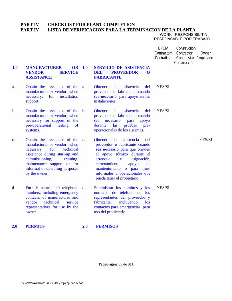
E:\Common\Newman\PRE-OP-REV.1\preop. part IV.doc
Page/Página 95 de 311
PART IV CHECKLIST FOR PLANT COMPLETIONPART IV LISTA DE VERIFICACION PARA LA TERMINACION DE LA PLANTA
WORK RESPONSIBILITY/RESPONSABLE POR TRABAJO
EPCMContractor/Contratista
ConstructionContractorContratista/
Construcción
OwnerPropietario
1.0 MANUFACTURER ORVENDOR SERVICEASSISTANCE
1.0 SERVICIO DE ASISTENCIADEL PROVEEDOR OFABRICANTE
a. Obtain the assistance of themanufacturer or vendor, whennecessary, for installationsupport.
a. Obtener la asistencia delproveedor o fabricante, cuandosea necesario, para apoyo en lasinstalaciones.
YES/SI
b. Obtain the assistance of themanufacturer or vendor, whennecessary for support of thepre-operational testing ofsystems.
b. Obtener la asistencia delproveedor o fabricante, cuandosea necesario, para apoyodurante las pruebas pre-operacionales de los sistemas.
YES/SI
c. Obtain the assistance of themanufacturer or vendor, whennecessary for technicalassistance during start-up andcommissioning, training,maintenance support or forinformal or operating purposesby the owner.
c. Obtener la asistencia delproveedor o fabricante cuandosea necesario para que brindenel apoyo técnico durante elarranque y asignación,entrenamiento, apoyo demantenimiento o para finesinformales u operacionales quepueda tener el propietario.
YES/SI
d. Furnish names and telephonenumbers, including emergencycontacts, of manufacturer andvendor technical servicerepresentatives for use by theowner.
d. Suministrar los nombres y losnúmeros de teléfono de losrepresentantes del proveedor yfabricante, incluyendo loscontactos para emergencias, parauso del propietario.
YES/SI
2.0 PERMITS 2.0 PERMISOS
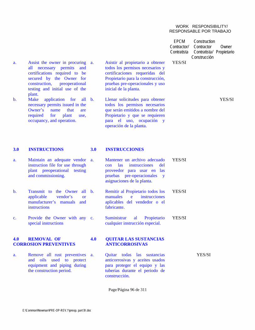
E:\Common\Newman\PRE-OP-REV.1\preop. part IV.doc
Page/Página 96 de 311
WORK RESPONSIBILITY/RESPONSABLE POR TRABAJO
EPCMContractor/Contratista
ConstructionContractorContratista/
Construcción
OwnerPropietario
a. Assist the owner in procuringall necessary permits andcertifications required to besecured by the Owner forconstruction, preoperationaltesting and initial use of theplant.
a. Asistir al propietario a obtenertodos los permisos necesarios ycertificaciones requeridas delPropietario para la construcción,pruebas pre-operacionales y usoinicial de la planta.
YES/SI
b. Make application for allnecessary permits issued in theOwner’s name that arerequired for plant use,occupancy, and operation.
b. Llenar solicitudes para obtenertodos los permisos necesariosque serán emitidos a nombre delPropietario y que se requierenpara el uso, ocupación yoperación de la planta.
YES/SI
3.0 INSTRUCTIONS 3.0 INSTRUCCIONES
a. Maintain an adequate vendorinstruction file for use throughplant preoperational testingand commissioning.
a. Mantener un archivo adecuadocon las instrucciones delproveedor para usar en laspruebas pre-operacionales yasignaciones de la planta.
YES/SI
b. Transmit to the Owner allapplicable vendor’s ormanufacturer’s manuals andinstructions
b. Remitir al Propietario todos losmanuales e instruccionesaplicables del vendedor o elfabricante.
YES/SI
c. Provide the Owner with anyspecial instructions
c. Suministrar al Propietariocualquier instrucción especial.
YES/SI
4.0 REMOVAL OFCORROSION PREVENTIVES
4.0 QUITAR LAS SUSTANCIASANTICORROSIVAS
a. Remove all rust preventivesand oils used to protectequipment and piping duringthe construction period.
a. Quitar todas las sustanciasanticorrosivas y aceites usadospara proteger el equipo y lastuberías durante el periodo deconstrucción.
YES/SI
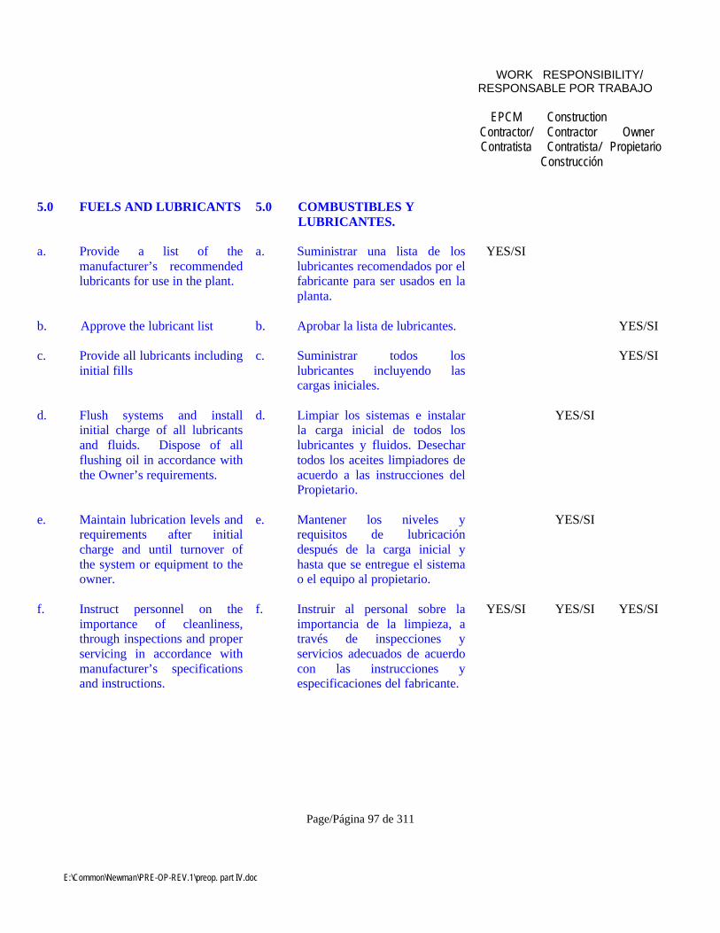
E:\Common\Newman\PRE-OP-REV.1\preop. part IV.doc
Page/Página 97 de 311
WORK RESPONSIBILITY/RESPONSABLE POR TRABAJO
EPCMContractor/Contratista
ConstructionContractorContratista/
Construcción
OwnerPropietario
5.0 FUELS AND LUBRICANTS 5.0 COMBUSTIBLES YLUBRICANTES.
a. Provide a list of themanufacturer’s recommendedlubricants for use in the plant.
a. Suministrar una lista de loslubricantes recomendados por elfabricante para ser usados en laplanta.
YES/SI
b. Approve the lubricant list b. Aprobar la lista de lubricantes. YES/SI
c. Provide all lubricants includinginitial fills
c. Suministrar todos loslubricantes incluyendo lascargas iniciales.
YES/SI
d. Flush systems and installinitial charge of all lubricantsand fluids. Dispose of allflushing oil in accordance withthe Owner’s requirements.
d. Limpiar los sistemas e instalarla carga inicial de todos loslubricantes y fluidos. Desechartodos los aceites limpiadores deacuerdo a las instrucciones delPropietario.
YES/SI
e. Maintain lubrication levels andrequirements after initialcharge and until turnover ofthe system or equipment to theowner.
e. Mantener los niveles yrequisitos de lubricacióndespués de la carga inicial yhasta que se entregue el sistemao el equipo al propietario.
YES/SI
f. Instruct personnel on theimportance of cleanliness,through inspections and properservicing in accordance withmanufacturer’s specificationsand instructions.
f. Instruir al personal sobre laimportancia de la limpieza, através de inspecciones yservicios adecuados de acuerdocon las instrucciones yespecificaciones del fabricante.
YES/SI YES/SI YES/SI

E:\Common\Newman\PRE-OP-REV.1\preop. part IV.doc
Page/Página 98 de 311
WORK RESPONSIBILITY/RESPONSABLE POR TRABAJO
EPCMContractor/Contratista
ConstructionContractorContratista/
Construcción
OwnerPropietario
g. Provide adequate space forstorage, cleaning, handling,and dispensing ofservicing/lubrication supplies.
g. Suministrar el espacio adecuadopara el almacenaje, limpieza,manejo y repartición de lossuministros de lubricación/mantenimiento.
YES/SI
h. Fill out and affix lubricant tagsto lubricant points.
h. Llenar y colocar las etiquetas delos lubricantes en los puntos delubricación.
YES/SI
i. A computer data base, orequivalent system shall bemaintained to keep track oflubricant inventory, equipmentservicing, lubricationinstructions, type/specificationand quantity of lubricant, andany other pertinent data.
i. Se mantendrá una base de datoscomputarizada, o un sistemaequivalente para mantener elinventario de lubricantes, elservicio de mantenimiento deequipos, instrucciones delubricación, tipo/ especificacióny cantidad de lubricante, ycualquier otro dato pertinente.
YES/SI
j. Flush clean all equipmentassembled in the field andinspect before servicing.
j. Limpiar todo el equipo armadoen el terreno e inspeccionarantes de realizar los servicios.
YES/SI
k. Prior to servicing oil reservoirinteriors, a thorough inspectionshall be made for cleanlinessand the surface paint examinedfor proper coating. The supplyand return piping shall beblown down with compressedair, prior to final connections.
k. Antes de realizar los servicios alos interiores de los depósitosde aceite, se realizará unainspección de limpieza a fondoy se verificará que la superficiepintada esté bien hecha. Lastuberías suministradas yaquellas devueltas se limpiaráncon aire comprimido antes de suconexión final.
YES/SI
l. Vent sight gauges on oil bathunits to reflect true oil level.
l. Pasar los indicadores visualesen unidades de baños de aceitepara que reflejen el nivelverdadero de aceite.
YES/SI

E:\Common\Newman\PRE-OP-REV.1\preop. part IV.doc
Page/Página 99 de 311
WORK RESPONSIBILITY/RESPONSABLE POR TRABAJO
EPCMContractor/Contratista
ConstructionContractorContratista/
Construcción
OwnerPropietario
m. On grease packed ball androller bearings, drain and ventplugs shall be removed both onservicing and during initialrun-in.
m. En los rodamientos de rodillos ybolas cubiertas de grasa, sequitarán los tapones deventilación y de drenaje para lapuesta en marcha inicial y parael mantenimiento.
YES/SI
n. Electrical and instrumentationcontrol and safeguards forforced oiling systems shall befunctionally demonstrated afterservicing to verify properoperation.
n. Los controles eléctricos, lainstrumentación y los elementosde protección de todos lossistemas de lubricación forzadaserán puestos enfuncionamiento después de losservicios para verificar quefuncionan correctamente.
YES/SI
o. Drive cylinders for hydraulicoil systems shall be activatedand stroked through theiroperation cycle. Asapplicable, purging shall beperformed to removeentrapped air.
o. Los cilindros impulsores de lossistemas de aceite hidráulico seactivarán y controlarán durantesu ciclo operacional. Si fuesenecesario, se realizaránpurgaciones para quitar el aireatrapado.
YES/SI
p. On pinion and driveassemblies, the initial lubricantcoating shall be appliedmanually for surface covering.Automatic fluid spray unitsshall be adjusted for properpattern and sequence timingprior to initial run-in ofequipment.
p. Se aplicará manualmente unaprimera mano de lubricante paracubrir el montaje de engranajesy piñones. Las unidades conrocíos de fluido automáticoserán calibradas para que tenganla configuración y la secuenciade tiempo adecuadas antes delfuncionamiento inicial delequipo.
YES/SI

E:\Common\Newman\PRE-OP-REV.1\preop. part IV.doc
Page/Página 100 de 311
WORK RESPONSIBILITY/RESPONSABLE POR TRABAJO
EPCMContractor/Contratista
ConstructionContractorContratista/
Construcción
OwnerPropietario
q. Oil leaks involving joints,connections, seals, etc. shall berepaired by disassembly andrefitting. No caulking or othercompounds shall be applied tojoints to remedy leaks.
q. Pérdidas de aceite que seencuentran en juntas,conexiones, sellos, etc. seránreparadas con trabajos dedesarmado y reajuste. No seaplicarán calafateos u otroscompuestos para remediar laspérdidas de las juntas.
YES/SI
r. As applicable, lube oil andhydraulic lines shall bechemically cleaned. Ownerapproved cleaning proceduresshall follow manufacturer’srecommendations.
r. Se limpiarán químicamente,según corresponda, el aceite delubricación y las líneashidráulicas. Los procedimientosde limpieza aprobados por elPropietario seguirán lasrecomendaciones del fabricante.
YES/SI
s. During test, if equipment isfound to be faulty or defectiveas a result of improperlubrication, the requiredrepairs or replacements shallbe made at the contractor’sexpense and the equipmentsubsequently re-tested.
s. Si durante las pruebas sedescubre que el equipo tienefallas o está defectuoso comoresultado de una lubricacióninadecuada, los arreglosnecesarios o los reemplazos serealizarán a costo del contratistay el equipo será porconsiguiente vuelto a probar.
YES/SI
6.0 REMOVAL OFTEMPORARY BRACINGAND SUPPORTS
6.0 QUITAR LOS APOYOS YARROSTRIAMIENTOSTEMPORARIOS
a. Remove all temporary orconstruction bracing supportsor other foreign objects fromtanks, ducts, or machinery.
a. Quitar todos los arrostramientostemporarios de apoyo de laconstrucción o cualquier otroobjeto foráneo de los tanques,tuberías o maquinaria.
YES/SI
7.0 ROTATION ANDALIGNMENT
7.0 ALINEACIÓN YROTACION
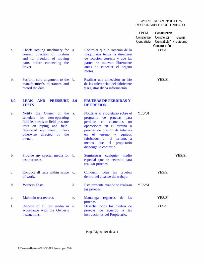
E:\Common\Newman\PRE-OP-REV.1\preop. part IV.doc
Page/Página 101 de 311
WORK RESPONSIBILITY/RESPONSABLE POR TRABAJO
EPCMContractor/Contratista
ConstructionContractorContratista/
Construcción
OwnerPropietario
a. Check rotating machinery forcorrect direction of rotationand for freedom of movingparts before connecting thedriver.
a. Controlar que la rotación de lamaquinaria tenga la direcciónde rotación correcta y que laspartes se muevan librementeantes de conectar el órganomotor.
YES/SI
b. Perform cold alignment to themanufacturer’s tolerances andrecord the data.
b. Realizar una alineación en fríode las tolerancias del fabricantey registrar dicha información.
YES/SI
8.0 LEAK AND PRESSURETESTS
8.0 PRUEBAS DE PERDIDAS YDE PRESION.
a. Notify the Owner of theschedule for non-operatingfield leak tests or field pressuretests on piping and field-fabricated equipment, unlessotherwise directed by theowner.
a. Notificar al Propietario sobre elprograma de pruebas paraperdidas en elementos nooperaciones en el terreno opruebas de presión de tuberíasen el terreno y equiposfabricados en el terreno, amenos que el propietariodisponga lo contrario.
YES/SI
b. Provide any special media fortest purposes.
b. Suministrar cualquier medioespecial que se necesite pararealizar pruebas.
YES/SI
c. Conduct all tests within scopeof work.
c. Conducir todas las pruebasdentro del alcance del trabajo.
YES/SI
d. Witness Tests d. Esté presente cuando se realizanlas pruebas.
YES/SI
e. Maintain test records e. Mantenga registros de laspruebas.
YES/SI
f. Dispose of all test media inaccordance with the Owner’sinstructions.
e. Deseche todos los medios depruebas de acuerdo a lasinstrucciones del Propietario.
YES/SI

E:\Common\Newman\PRE-OP-REV.1\preop. part IV.doc
Page/Página 102 de 311
WORK RESPONSIBILITY/RESPONSABLE POR TRABAJO
EPCMContractor/Contratista
ConstructionContractorContratista/
Construcción
OwnerPropietario
9.0 INSPECTION 9.0 INSPECCIONES
a. Provide inspection of the plantto verify that erected facilitiesconform to flow diagrams,construction drawings, vendorprints and specifications.
a. Conducir inspecciones de laplanta para verificar si lasinstalaciones se han construidosegún los diagramas y dibujosde fabricación, los diseños yespecificaciones del proveedor.
YES/SI
b. Perform shop inspection andwitness tests, as required.
b. Conducir inspecciones de lostalleres y de las pruebaspresenciadas, según corresponda.
YES/SI
10.0 FLUSHING ANDCLEANING OPERATIONS
10.0 OPERACIONES DELIMPIEZA PORDESCARGA DE AGUA YOTRAS.
a. Conduct all flushing andcleaning operations inaccordance with the pipingspecification.
a. Conducir todas las operacionesde limpieza incluyo aquellaspor descarga de agua deacuerdo a la especificación dela tubería.
YES/SI
b. Provide any special media forflushing and cleaning.
b. Suministrar cualquier medioespecial que se necesite pararealizar las limpiezas.
YES/SI
c. Dispose of all media inaccordance with Owner’srequirements.
c. Desechar todos los medios deacuerdo a los requisitos delPropietario.
YES/SI
d. Maintain records as requiredfor turnover.
d. Mantener los registros que senecesiten para la entrega.
YES/SI
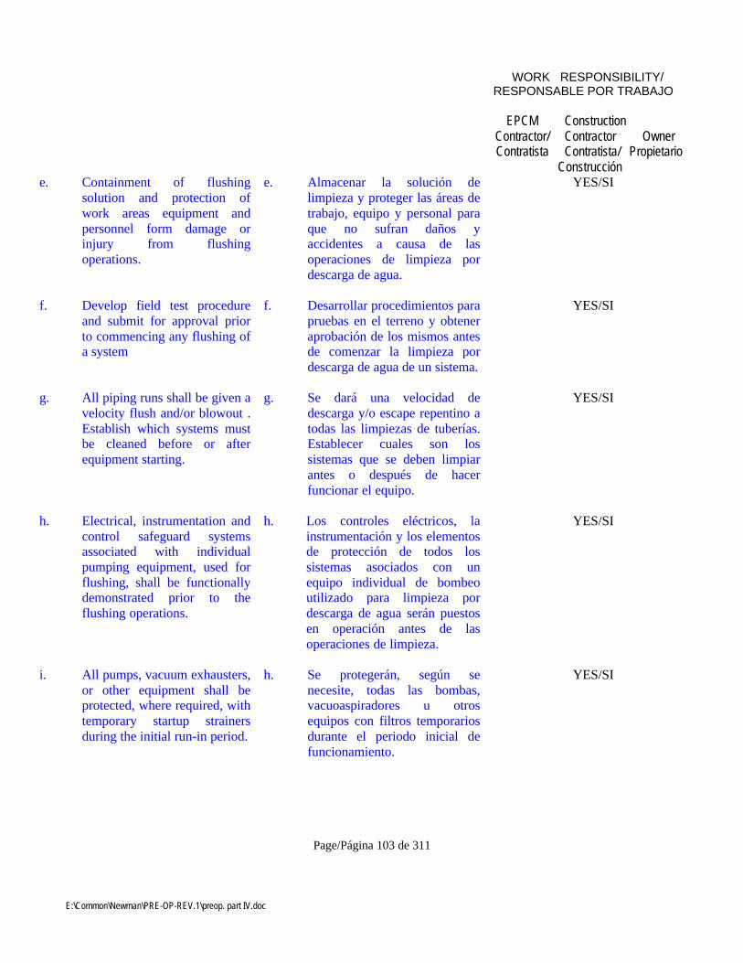
E:\Common\Newman\PRE-OP-REV.1\preop. part IV.doc
Page/Página 103 de 311
WORK RESPONSIBILITY/RESPONSABLE POR TRABAJO
EPCMContractor/Contratista
ConstructionContractorContratista/
Construcción
OwnerPropietario
e. Containment of flushingsolution and protection ofwork areas equipment andpersonnel form damage orinjury from flushingoperations.
e. Almacenar la solución delimpieza y proteger las áreas detrabajo, equipo y personal paraque no sufran daños yaccidentes a causa de lasoperaciones de limpieza pordescarga de agua.
YES/SI
f. Develop field test procedureand submit for approval priorto commencing any flushing ofa system
f. Desarrollar procedimientos parapruebas en el terreno y obteneraprobación de los mismos antesde comenzar la limpieza pordescarga de agua de un sistema.
YES/SI
g. All piping runs shall be given avelocity flush and/or blowout .Establish which systems mustbe cleaned before or afterequipment starting.
g. Se dará una velocidad dedescarga y/o escape repentino atodas las limpiezas de tuberías.Establecer cuales son lossistemas que se deben limpiarantes o después de hacerfuncionar el equipo.
YES/SI
h. Electrical, instrumentation andcontrol safeguard systemsassociated with individualpumping equipment, used forflushing, shall be functionallydemonstrated prior to theflushing operations.
h. Los controles eléctricos, lainstrumentación y los elementosde protección de todos lossistemas asociados con unequipo individual de bombeoutilizado para limpieza pordescarga de agua serán puestosen operación antes de lasoperaciones de limpieza.
YES/SI
i. All pumps, vacuum exhausters,or other equipment shall beprotected, where required, withtemporary startup strainersduring the initial run-in period.
h. Se protegerán, según senecesite, todas las bombas,vacuoaspiradores u otrosequipos con filtros temporariosdurante el periodo inicial defuncionamiento.
YES/SI

E:\Common\Newman\PRE-OP-REV.1\preop. part IV.doc
Page/Página 104 de 311
WORK RESPONSIBILITY/RESPONSABLE POR TRABAJO
EPCMContractor/Contratista
ConstructionContractorContratista/
Construcción
OwnerPropietario
j. Determine flushing or blow-out routes which increasecleaning effectiveness andinstall temporary piping,fittings, strainers, etc. asnecessary.
i. Determinar las rutas dedescarga o escape queaumenten la efectividad de lalimpieza e instalar tuberías,juntas y filtros temporarios, etc.cuando fuese necesario.
YES/SI
k. Before starting a pump,compressor or similarequipment for the first time theinlet piping shall be confirmedto be clean. Tanks shall behand cleaned, hosed down,inspected and filled withsuitable flushing media. Thesuction line shall then bedisconnected as close to theequipment as practical andwater flushed to waste toensure that there are notobstruction and that all debrisis removed.
j. Antes de hacer funcionar unabomba, un compresor o unequipo similar por primera vez,se verificará que los tubos deadmisión estén limpios. Lostanques se limpiarán a mano, selavarán con chorros demangueras, se inspeccionarán yllenarán con los mediosapropiados para la limpieza pordescarga de agua. La línea desucción será desconectada tancerca del equipo como seapráctico y se desechará el aguapara asegurarse que no hayninguna obstrucción y que todala basura ha sido quitada.
YES/SI
l. Remove all orifice plates andother inline devices prior toflushing.
k. Quitar todas las planchas de losorificios y de otros dispositivosde líneas antes de efectuar lalimpieza por descarga de agua.
YES/SI
m. Ensure that excessive flow orpressure shall not causedamage to the system.
l. Asegurarse que el flujo y/opresión excesivos no causarándaños al sistema.
YES/SI
n. Continuously monitorequipment for damage duringthe flushing or cleaning.
m. Controlar continuamente elequipo durante la limpieza, yasea por descarga de agua u otra,para ver si hay algún daño.
YES/SI
E:\Common\Newman\PRE-OP-REV.1\preop. part IV.doc
Page/Página 105 de 311
WORK RESPONSIBILITY/RESPONSABLE POR TRABAJO
EPCMContractor/Contratista
ConstructionContractorContratista/
Construcción
OwnerPropietario
o. Chemically clean carbon steeloil and hydraulic piping toremove mill scale prior tosystem flushing.
n. Limpiar químicamente conkerosene el acero y las tuberíashidráulicas para quitar lacascarilla de laminación antesde la limpieza de descarga delsistema.
YES/SI
p. Velocity flush lubricant and/orhydraulic oil piping.
o. Ejecutar descargas rápidas delimpieza en las tuberías delubricantes y/o de aceitehidráulico.
YES/SI
q. Monitor strainer differentialpressures during theflushing/cleaning operation toensure differential pressure isnot excessive.
p. Controlar la presión diferencialdel filtro durante la operaciónde descarga y de limpieza paraasegurarse que la presióndiferencial no sea excesiva.
YES/SI
r. At the conclusion of systemflushing, remove all temporarypiping, fittings andconnections and make up thepermanent piping.
q. Al concluir la limpieza delsistema por descarga de agua,quitar todas las tuberías, juntasy conexiones temporarias ymontar las tuberíaspermanentes.
YES/SI
11.0 CONTAINMENT 11.0 CONFINAMIENTO
a. Internal cleanliness shall berequired prior to “charging”the equipment or system to betested. Suitable isolationprotection shall be providedwhere equipment, meters,relief valves, etc. are requiredto be tested.
a. Se requerirá la limpieza internaantes de “cargar” al equipo osistema a probar. Se proveerá laprotección de aislamientocorrespondiente donde serequiera probar el equipo,medidores, válvulas dedescarga, etc.
YES/SI
E:\Common\Newman\PRE-OP-REV.1\preop. part IV.doc
Page/Página 106 de 311
WORK RESPONSIBILITY/RESPONSABLE POR TRABAJO
EPCMContractor/Contratista
ConstructionContractorContratista/
Construcción
OwnerPropietario
b. Temporary piping fitting andother equipment required forcertain tests shall betemporarily installed andremoved after satisfactorytesting.
b. Los accesorios temporarios detuberías y otros equipos que serequieren para ciertas pruebasse instalarán temporariamente yse quitarán después que laspruebas sean realizadassatisfactoriamente.
YES/SI
c. System piping and instrumentdiagrams and piping isometricsshall be used as a reference fortesting. Progress shall beillustrated by the technique of“color-out” on diagrams.
c. Se utilizará un sistema detubería, diagramas deinstrumentos e isometría detuberías como referencia parahacer las pruebas. Se ilustrará elprogreso usando la técnica de“pintar en colores” sobre losdiagramas.
YES/SI
d. In order to locate the majorpiping leaks, a preliminary airtest of not more than 50 psig or1/3 of the system rating, whichever is lower, may be madeprior to hydrostatic testing.
d. Se podrá realizar una pruebapreliminar de aire de no más de50 psig o un 1/3 del sistemanormal, el que resulte más bajo,antes de las pruebashidrostáticas con el fin deubicar las pérdidas más grandesen la tubería.
YES/SI
e. Upon completion ofhydrostatic tests requiring “wetfill”, all high points shall bevented and the system drained,as soon as practical.
e. Una ves terminadas las pruebashidrostáticas que requieran“rellenos mojados”, seventilarán todos los puntos altosy se drenará el sistema tanpronto como sea práctico.
YES/SI
E:\Common\Newman\PRE-OP-REV.1\preop. part IV.doc
Page/Página 107 de 311
WORK RESPONSIBILITY/RESPONSABLE POR TRABAJO
EPCMContractor/Contratista
ConstructionContractorContratista/
Construcción
OwnerPropietario
f. Adequate temporary supportsshall be provided for piping inother than liquid service whenhydrostatic testing isperformed. Manual valvesundergoing hydrostatic testsshall be kept in the openposition. Control valves shallbe isolated or removed asapplicable to avoid damage.
f. Se suministrarán apoyostemporarios adecuados para lacolocación de tubería, apartedel servicio líquido, cuando serealicen las pruebashidrostáticas. Las válvulasmanuales que se someten apruebas hidrostáticas se deberánmantener en la posición abierta.Las válvulas de control seránaisladas y quitadas como seanecesario para evitar daños.
YES/SI
g. Unless otherwise specified, allunderground sections of pipingshall undergo either hydro orpneumatic pressure tests priorto backfilling. Nondrainablesections of wet tested systemsshall be blown out, unlesswater lines are put intoimmediate service.
g. A menos que se especifique locontrario, todas las secciones detuberías subterráneas seránsometidas a pruebashidrostáticas o de presiónneumática antes de sercolocadas y rellenadas. Lassecciones no drenables de lossistemas mojados probadosserán destruidas a menos quelas líneas de agua seaninmediatamente puestas enservicio.
YES/SI
h. Rupture disks and safetyvalves must be isolated orremoved for hydrostatic tests.
h. Los discos de ruptura y lasválvulas de seguridad deberánser aislados o quitadas pararealizar las pruebashidrostáticas.
YES/SI
12.0 ELECTRICAL 12.0 ELECTRICOS
E:\Common\Newman\PRE-OP-REV.1\preop. part IV.doc
Page/Página 108 de 311
WORK RESPONSIBILITY/RESPONSABLE POR TRABAJO
EPCMContractor/Contratista
ConstructionContractorContratista/
Construcción
OwnerPropietario
a. Inspect all electrical equipmentsuch as transformers,switchgear, motor controlcenters, motors and electricalhardware for proper location,adequate fastening in place,proper connections, properrating, correct marking andlabeling and test for continuity,grounding, protection,operation and run-in.
a. Inspeccionar todos los equiposeléctricos tales como lostransformadores, los centros decontrol de motores, motores yhardware eléctricos paraverificar que están colocadoscorrectamente, que tienen lasataduras en su lugar, lasconexiones apropiadas, lagraduación apropiada, lasetiquetas y las marcas correctasy las pruebas de continuidad, depuesta a tierra, protección,operación y funcionamiento.
YES/SI
b. Test all power and controlcable as applicable for openand short circuits, continuityand leakage.
b. Probar todos los cables ycontroles eléctricos, lacontinuidad y perdidas, comosea necesario, de los circuitosabiertos y los circuitos cortos.
YES/SI
c. Upon completion of testing ofall individual units in a system,the entire system shall be run-in to ensure proper operation.
c. Una vez terminadas las pruebasde todas las unidadesindividuales de un sistema, sehará operar al sistema completopara asegurarse que funcionacorrectamente.
YES/SI
d. Actual connections shall becompared with schematic andelementary wiring diagramsand mismatches shall berectified as appropriate.
d. Las conexiones verdaderasserán comparadas con losesquemas y con los diagramasbásicos de instalacioneseléctricas, y los desajustes quese encuentren serán corregidoscomo corresponda.
YES/SI
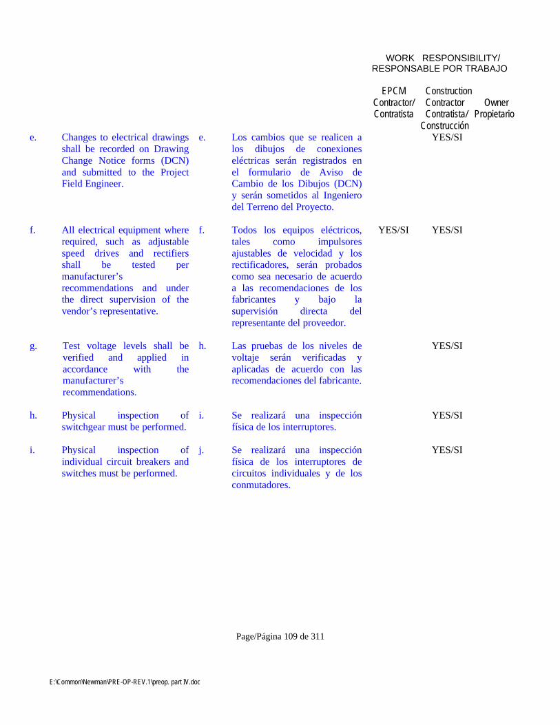
E:\Common\Newman\PRE-OP-REV.1\preop. part IV.doc
Page/Página 109 de 311
WORK RESPONSIBILITY/RESPONSABLE POR TRABAJO
EPCMContractor/Contratista
ConstructionContractorContratista/
Construcción
OwnerPropietario
e. Changes to electrical drawingsshall be recorded on DrawingChange Notice forms (DCN)and submitted to the ProjectField Engineer.
e. Los cambios que se realicen alos dibujos de conexioneseléctricas serán registrados enel formulario de Aviso deCambio de los Dibujos (DCN)y serán sometidos al Ingenierodel Terreno del Proyecto.
YES/SI
f. All electrical equipment whererequired, such as adjustablespeed drives and rectifiersshall be tested permanufacturer’srecommendations and underthe direct supervision of thevendor’s representative.
f. Todos los equipos eléctricos,tales como impulsoresajustables de velocidad y losrectificadores, serán probadoscomo sea necesario de acuerdoa las recomendaciones de losfabricantes y bajo lasupervisión directa delrepresentante del proveedor.
YES/SI YES/SI
g. Test voltage levels shall beverified and applied inaccordance with themanufacturer’srecommendations.
h. Las pruebas de los niveles devoltaje serán verificadas yaplicadas de acuerdo con lasrecomendaciones del fabricante.
YES/SI
h. Physical inspection ofswitchgear must be performed.
i. Se realizará una inspecciónfísica de los interruptores.
YES/SI
i. Physical inspection ofindividual circuit breakers andswitches must be performed.
j. Se realizará una inspecciónfísica de los interruptores decircuitos individuales y de losconmutadores.
YES/SI

E:\Common\Newman\PRE-OP-REV.1\preop. part IV.doc
Page/Página 110 de 311
WORK RESPONSIBILITY/RESPONSABLE POR TRABAJO
EPCMContractor/Contratista
ConstructionContractorContratista/
Construcción
OwnerPropietario
j. Check line-up and ease ofoperation of each circuitbreaker carriage for insertionand withdrawal in each of theoperating, test anddisconnected positions,ensuring proper main andauxiliary contact alignment,shutter operation andfunctioning of interlocks.Check manual closing andtripping of circuit breaker.
k. Controlar las coincidencias y lafacilidad de operación de cadacaja de disyuntores paraverificar la inserción y la salida,durante la operación, prueba ydesconexión de las posiciones,asegurándose que tengan laalineación de contacto principaly auxiliar apropiadas, como asítambién las operaciones decierre y el funcionamiento delos interbloqueos. Controlar elcierre manual y la interrupciónde los disyuntores.
YES/SI
k. Check phasing of incomingand outgoing circuits to ensurecontinuity of each phase withinthe switchgear.
l. Controlar las fases de loscircuitos de entrada y de salidapara asegurar la continuidad decada fase dentro del aparato deconexión.
YES/SI
l. Make an electrical continuitycheck of all current, potentialand control circuits. Refer towiring diagrams and comparethe diagrams with actualconnections. Correct diagramsand/or connections as required.Carry out ducter tests onbusbars and primary switchingdevices.
m. Realizar un control decontinuidad eléctrica en todoslos circuitos actuales,potenciales y de control. Verlos diagramas de instalacióneléctrica y comparar con losdiagramas de instalacionesactuales. Corregir los diagramasy/o las conexiones, segúncorresponda. Conducir pruebasen las barras colectoras y en losdispositivos conmutadoresprimarios con el instrumento demedidas para lectura directa deresistencias pequeñas.
YES/SI
m. Check all switchgearprotective and meteringcircuits.
n. Controlar la protección de todoslos aparatos de conexión y loscircuitos de medición.
YES/SI
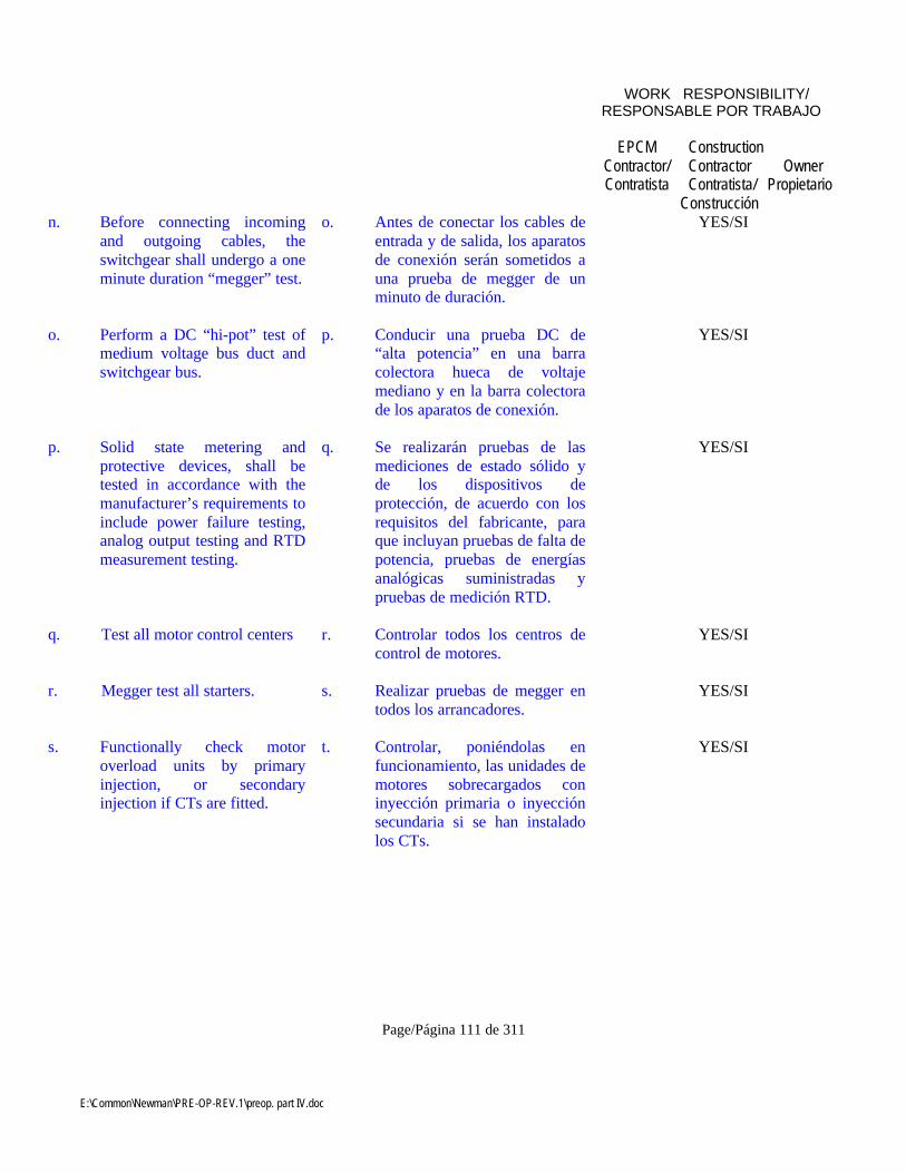
E:\Common\Newman\PRE-OP-REV.1\preop. part IV.doc
Page/Página 111 de 311
WORK RESPONSIBILITY/RESPONSABLE POR TRABAJO
EPCMContractor/Contratista
ConstructionContractorContratista/
Construcción
OwnerPropietario
n. Before connecting incomingand outgoing cables, theswitchgear shall undergo a oneminute duration “megger” test.
o. Antes de conectar los cables deentrada y de salida, los aparatosde conexión serán sometidos auna prueba de megger de unminuto de duración.
YES/SI
o. Perform a DC “hi-pot” test ofmedium voltage bus duct andswitchgear bus.
p. Conducir una prueba DC de“alta potencia” en una barracolectora hueca de voltajemediano y en la barra colectorade los aparatos de conexión.
YES/SI
p. Solid state metering andprotective devices, shall betested in accordance with themanufacturer’s requirements toinclude power failure testing,analog output testing and RTDmeasurement testing.
q. Se realizarán pruebas de lasmediciones de estado sólido yde los dispositivos deprotección, de acuerdo con losrequisitos del fabricante, paraque incluyan pruebas de falta depotencia, pruebas de energíasanalógicas suministradas ypruebas de medición RTD.
YES/SI
q. Test all motor control centers r. Controlar todos los centros decontrol de motores.
YES/SI
r. Megger test all starters. s. Realizar pruebas de megger entodos los arrancadores.
YES/SI
s. Functionally check motoroverload units by primaryinjection, or secondaryinjection if CTs are fitted.
t. Controlar, poniéndolas enfuncionamiento, las unidades demotores sobrecargados coninyección primaria o inyecciónsecundaria si se han instaladolos CTs.
YES/SI
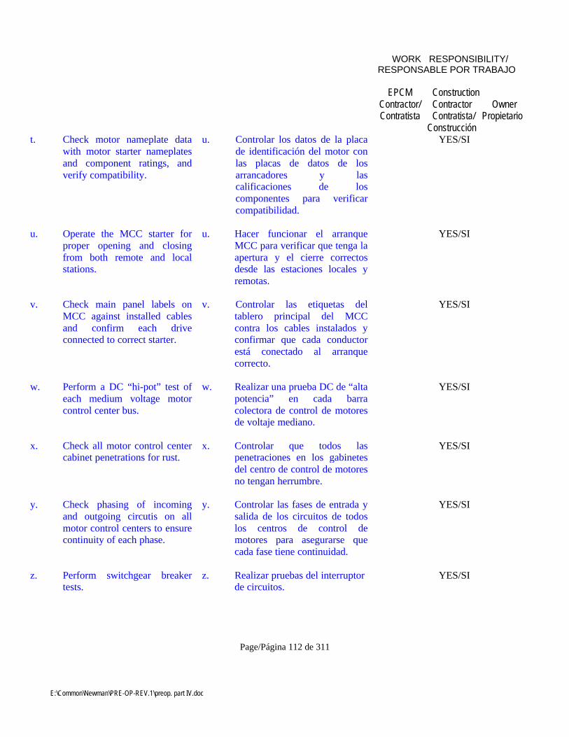
E:\Common\Newman\PRE-OP-REV.1\preop. part IV.doc
Page/Página 112 de 311
WORK RESPONSIBILITY/RESPONSABLE POR TRABAJO
EPCMContractor/Contratista
ConstructionContractorContratista/
Construcción
OwnerPropietario
t. Check motor nameplate datawith motor starter nameplatesand component ratings, andverify compatibility.
u. Controlar los datos de la placade identificación del motor conlas placas de datos de losarrancadores y lascalificaciones de loscomponentes para verificarcompatibilidad.
YES/SI
u. Operate the MCC starter forproper opening and closingfrom both remote and localstations.
u. Hacer funcionar el arranqueMCC para verificar que tenga laapertura y el cierre correctosdesde las estaciones locales yremotas.
YES/SI
v. Check main panel labels onMCC against installed cablesand confirm each driveconnected to correct starter.
v. Controlar las etiquetas deltablero principal del MCCcontra los cables instalados yconfirmar que cada conductorestá conectado al arranquecorrecto.
YES/SI
w. Perform a DC “hi-pot” test ofeach medium voltage motorcontrol center bus.
w. Realizar una prueba DC de “altapotencia” en cada barracolectora de control de motoresde voltaje mediano.
YES/SI
x. Check all motor control centercabinet penetrations for rust.
x. Controlar que todos laspenetraciones en los gabinetesdel centro de control de motoresno tengan herrumbre.
YES/SI
y. Check phasing of incomingand outgoing circutis on allmotor control centers to ensurecontinuity of each phase.
y. Controlar las fases de entrada ysalida de los circuitos de todoslos centros de control demotores para asegurarse quecada fase tiene continuidad.
YES/SI
z. Perform switchgear breakertests.
z. Realizar pruebas del interruptorde circuitos.
YES/SI

E:\Common\Newman\PRE-OP-REV.1\preop. part IV.doc
Page/Página 113 de 311
WORK RESPONSIBILITY/RESPONSABLE POR TRABAJO
EPCMContractor/Contratista
ConstructionContractorContratista/
Construcción
OwnerPropietario
Aa. Check switchgear trippingbattery.
Aa Controlar la batería deinterrupción del aparato deconexiones.
YES/SI
Ab. Check that all potentialtransformer fuses and controlfuses are the correct size andare installed.
Ab. Controlar que todos los fusiblesde transformadores potenciales ylos fusibles de control tienen eltamaño y la instalación correcta.
YES/SI
Ac. Check main switchgear panellabels against installed cablesand confirm that each panel isconnected to the correctdestination.
Ac. Controlar las etiquetas en eltablero del aparato principal deconexiones con los cablesinstalados y confirmar que cadatablero está conectado al puntode destino correcto.
YES/SI
Ad. Test and prove switchgearintertripping and pilot wireprotection.
Ad. Probar el disparointerdependiente del aparato deconexiones y la protección delhilo auxiliar.
YES/SI
Ae. All relays are to be set inaccordance with the relaysetting tabulations furnished.
Ae. Todos los relés deberán serregulados se acuerdo con lastablas de regulación para reléssuministradas.
YES/SI
Af. CT ratio, burden, polarity anddc resistance shall be checkedagainst the respectivedrawings.
Af. Se controlará la razón de CT, lacarga, la polaridad y laresistencia dc con los dibujosrespectivos.
YES/SI
Ag. Check all labels fixed neareach instrument or protectiverelay for correct data.
Ag. Controlar que la información escorrecta en todas las etiquetascolocadas cerca de cadainstrumento o relé protector.
YES/SI

E:\Common\Newman\PRE-OP-REV.1\preop. part IV.doc
Page/Página 114 de 311
WORK RESPONSIBILITY/RESPONSABLE POR TRABAJO
EPCMContractor/Contratista
ConstructionContractorContratista/
Construcción
OwnerPropietario
Ah. Establish the correct operationand calibration of panelmeters, including watt hourmeters, using appropriatevoltage and current injectionmethods.
Ah. Establecer la operación ycalibración correctas en eltablero de medidores, incluyendolos contadores de vatio-horausando el voltaje apropiado ymétodos de inyección decorriente.
YES/SI
Ai. Return out of calibration unitsto the vendor or re-calibration.
Ai. Devolver al proveedor todas lasunidades mal calibradas orecalibrarlas.
YES/SI
Aj. Perform all physicalinspections and tests ontransformers.
Aj. Realizar todas las pruebas y lasinspecciones físicas de lostransformadores.
YES/SI
Ak. Perform dielectric strengthtests on all insulating liquids inthe transformer.
Ak. Realizar todas las pruebas deresistencia dieléctrica en todoslos líquidos aisladores deltransformador.
YES/SI
Al. Check megger readings againstmanufacturer’s test certificatesfor factory sealed, liquid-submerged coils.
Al. Controlar las lecturas de meggercon los certificados de pruebasdel fabricante para verificar quelas bobinas están sumergidas enlíquido y selladas de fábrica.
YES/SI
Am. Check phasing of primary andsecondary circuits to ensurecontinuity of phases across thetransformer.
Am. Controlar las fases de loscircuitos primarios y secundariospara asegurarse de la continuidadde las fases en el transformador.
YES/SI

E:\Common\Newman\PRE-OP-REV.1\preop. part IV.doc
Page/Página 115 de 311
WORK RESPONSIBILITY/RESPONSABLE POR TRABAJO
EPCMContractor/Contratista
ConstructionContractorContratista/
Construcción
OwnerPropietario
An. Inspect, test and prepare allmotors for energization inaccordance with themanufacturer’s instructions.
An. Inspeccionar, probar y preparartodos los motores para que seanenergizados de acuerdo con lasinstrucciones del fabricante.
YES/SI
Ao. Check all motors for correctclearances, alignment andlubrication.
Ao. Controlar que todos los motorestengan los permisos, laalineación y la lubricacióncorrectas.
YES/SI
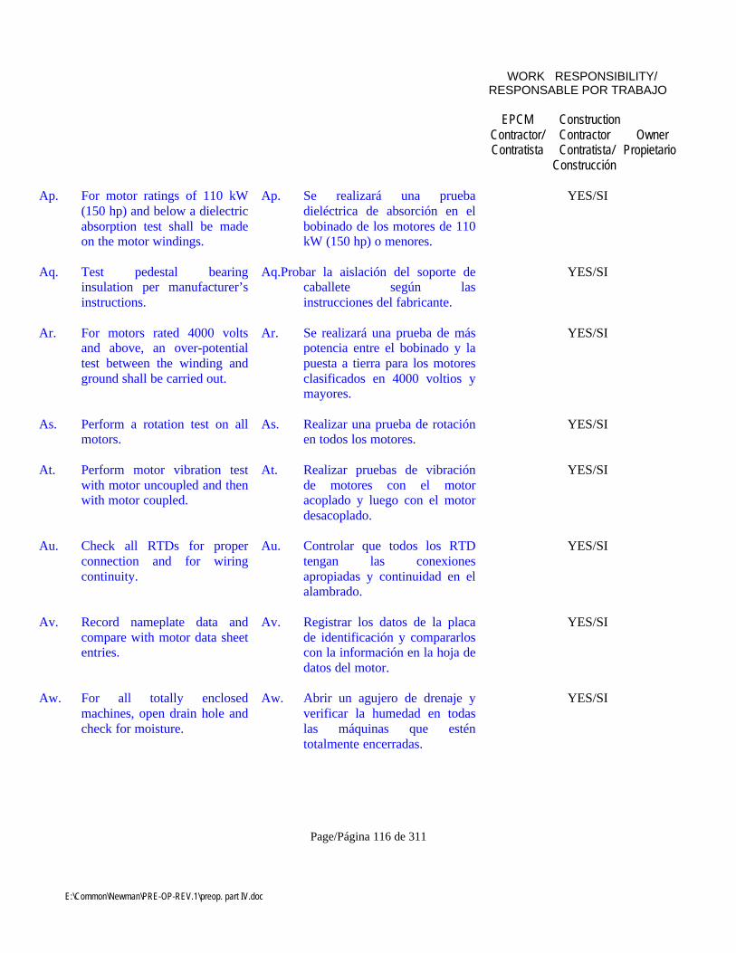
E:\Common\Newman\PRE-OP-REV.1\preop. part IV.doc
Page/Página 116 de 311
WORK RESPONSIBILITY/RESPONSABLE POR TRABAJO
EPCMContractor/Contratista
ConstructionContractorContratista/
Construcción
OwnerPropietario
Ap. For motor ratings of 110 kW(150 hp) and below a dielectricabsorption test shall be madeon the motor windings.
Ap. Se realizará una pruebadieléctrica de absorción en elbobinado de los motores de 110kW (150 hp) o menores.
YES/SI
Aq. Test pedestal bearinginsulation per manufacturer’sinstructions.
Aq.Probar la aislación del soporte decaballete según lasinstrucciones del fabricante.
YES/SI
Ar. For motors rated 4000 voltsand above, an over-potentialtest between the winding andground shall be carried out.
Ar. Se realizará una prueba de máspotencia entre el bobinado y lapuesta a tierra para los motoresclasificados en 4000 voltios ymayores.
YES/SI
As. Perform a rotation test on allmotors.
As. Realizar una prueba de rotaciónen todos los motores.
YES/SI
At. Perform motor vibration testwith motor uncoupled and thenwith motor coupled.
At. Realizar pruebas de vibraciónde motores con el motoracoplado y luego con el motordesacoplado.
YES/SI
Au. Check all RTDs for properconnection and for wiringcontinuity.
Au. Controlar que todos los RTDtengan las conexionesapropiadas y continuidad en elalambrado.
YES/SI
Av. Record nameplate data andcompare with motor data sheetentries.
Av. Registrar los datos de la placade identificación y compararloscon la información en la hoja dedatos del motor.
YES/SI
Aw. For all totally enclosedmachines, open drain hole andcheck for moisture.
Aw. Abrir un agujero de drenaje yverificar la humedad en todaslas máquinas que esténtotalmente encerradas.
YES/SI

E:\Common\Newman\PRE-OP-REV.1\preop. part IV.doc
Page/Página 117 de 311
WORK RESPONSIBILITY/RESPONSABLE POR TRABAJO
EPCMContractor/Contratista
ConstructionContractorContratista/
Construcción
OwnerPropietario
Ax. Measure insulation resistanceusing a 1 kV megger formotors less than 600 V and a 5kV megger for motors greaterthan 600 V.
Ax. Medir la resistencia deaislamiento usando un meggerde 1 kV en motores de menosde 600 V y un megger de 5 kVen motores mayores a 600 V.
YES/SI
Ay. Confirm oil levels areappropriate in all motors.
Ay. Confirmar que los niveles deaceite sean los correctos entodos los motores.
YES/SI
Az. Motors 37.5 kW (50 hp) andlarger shall be uncoupled andrun until motor temperaturestablizes or as specified in thevendor manual.
Az. Los motores de 37.5 kW (50hp) y mayores serándesacoplados y puestos enfuncionamiento hasta que latemperatura del motor seestabilice o como se especifiqueen el manual del proveedor.
YES/SI
Ba. Before energizing slip ringmotors check rotor resistancevalue and record theconnection layout of theresistors.
Ba. Verificar el valor de laresistencia del rotor y registrarel trazado de la conexión de losresistores antes de laenergización de los motores conanillos deslizantes.
YES/SI
Bb. On motors fitted withcondensation heaters andwinding temperature detectors,measure the resistance of thewinding temperature detectorsand megger the heaters.
Bb. Medir la resistencia de losdetectores de temperatura deldevanado y megger loscalefactores en los motoresequipados con calefactores decondensación y detectores detemperatura del devanado.
YES/SI
Bc. Visually inspect all wire andcable for faulty insulation priorto installation.
Bc. Inspeccionar visualmente todoel alambrado y el cableado paradetectar si existe aislamientodefectuoso antes de lainstalación.
YES/SI

E:\Common\Newman\PRE-OP-REV.1\preop. part IV.doc
Page/Página 118 de 311
WORK RESPONSIBILITY/RESPONSABLE POR TRABAJO
EPCMContractor/Contratista
ConstructionContractorContratista/
Construcción
OwnerPropietario
Bd. 600 V and 1000 V wire shallbe meggered for one minutewith a 1000 V insulation tester.
Bd. Los alambres de 600 V y 1000V serán probados con unmegger durante un minuto conun probador de aislamiento de1000 V.
YES/SI
Be. All power cables 2000 V andabove shall be meggered forone minute with a 5000 Vmegger after pulling, butbefore splicing or terminating.
Be. Todos los cables eléctricos de2000 V y más serán probadoscon un megger por un minutocon un megger de 5000 Vdespués del tiraje, pero antes delempalme o terminación.
YES/SI
Bf. All power cables above 2000V shall be tested after splicingand stress cones are completedbut before terminating.
Bf. Todos los cables eléctricosmayores de 2000 V seránprobados después del empalmey después que se hayancompletado los conos de tensiónpero antes de la terminación.
YES/SI
Bg. Test and check all control andinstrument cables.
Bg. Probar y controlar todos loscables de instrumentos y decontrol.
YES/SI
Bh. Test and check all controlcabinets, relay panels, lightingand power panels, junctionboxes and field mounteddevices as required.
Bh. Probar y controlar, segúncorresponda, todos los gabinetesde control, los tableros de relés,los tableros de iluminación y depotencia, cajas de conexiones ydispositivos armados en terreno.
YES/SI
Bi. Test and check all batteries andbattery chargers in accordancewith manufacturer’s manuals.
Bi. Probar y controlar todas lasbaterías y cargadores de bateríasde acuerdo a los manuales delfabricante.
YES/SI
Bj. Carry out capacity tests andfloat current test on eachbattery in accordance with themanufacturer’s instructions.
Bj. Conducir pruebas de capacidady pruebas de corrientecompensadora en cada bateríade acuerdo a las instruccionesdel fabricante.
YES/SI
E:\Common\Newman\PRE-OP-REV.1\preop. part IV.doc
Page/Página 119 de 311
WORK RESPONSIBILITY/RESPONSABLE POR TRABAJO
EPCMContractor/Contratista
ConstructionContractorContratista/
Construcción
OwnerPropietario
Bk. Check all fluid levels prior toenergizing any emergencygenerator.
Bk.Controlar todos los niveles defluidos antes de energizarcualquier generador deemergencia.
YES/SI
Bl. Grounding – The groundingsystem shall be checked toensure that all parts of steelstructures, motor frames,switch-gear, trays, conduitsand other electrical equipmentare grounded in accordancewith the drawings. Determineground grid resistances asspecified on groundingdrawings. Check all groundingtest bars and connections.Check separately that thecontrol and computer systemgrounding systems areadequate and effectivelyseparated. After completion ofindividual ground tests, theoverall grounding resistanceshall be measured andrecorded in a certified formalreport.
Bl. Puesta a tierra. El sistema depuesta a tierra será controladopara asegurarse que todas laspartes de las estructuras deacero, estructuras para motores,conmutadores, bandejas,conductos y otros equiposeléctricos están puestos a tierrade acuerdo a los dibujos.Determinar las resistencias de lared de energía de acuerdo a losdibujos de puesta a tierra.Controlar todas las barras depruebas de puesta a tierra y lasconexiones. Verificar porseparado que los sistemas depuesta a tierra en el sistema decomputación y de control sonadecuados y que estánseparados eficazmente. Despuésde completar las pruebasindividuales de puesta a tierra,la resistencia total de puesta atierra deberá ser medida yregistrada en un informe formalcertificado.
YES/SI
Bm. For lighting and small powercircuits, carry out all requiredtests on the circuits andequipment.
Bm. Se realizarán todas las pruebasque se requieran en los circuitosy los equipos para iluminacióny los circuitos de menorpotencia.
YES/SI
Bn. Perform functional tests on alllighting system.
Bn. Realizar pruebas defuncionamiento en todos lossistemas de iluminación.
YES/SI
E:\Common\Newman\PRE-OP-REV.1\preop. part IV.doc
Page/Página 120 de 311
WORK RESPONSIBILITY/RESPONSABLE POR TRABAJO
EPCMContractor/Contratista
ConstructionContractorContratista/
Construcción
OwnerPropietario
Bo. Perform required tests on heattracing.
Bo. Realizar las pruebas que senecesiten para la identificaciónde calor.
YES/SI
Bp. Lightning Protectioninspection and approval shallbe by the authority havingjurisdiction in the area.
BB. La inspección y aprobación dela Protección de la Iluminaciónserá realizadas por la autoridadque tiene jurisdicción en esaárea.
YES/SI
Bq. A certificate of compliance forlightning protection shall beissued by the authority havingjurisdiction and shall befurnished to the owner.
Bq. La autoridad con jurisdicciónemitirá un certificado decumplimiento con la protecciónde la iluminación y se loentregará al Propietario.
YES/SI
Br. Before any section ofunderground conduit iscovered with concrete orburied, each conduit shall betested for obstructions orflattening by drawing througha mandrel of the proper size.Immediately after the conduitbank has been covered orencased with concrete andbefore initial set takes place,the proper mandrel shall againbe run through each conduit.
Br. Antes de que cualquier secciónde conducto subterráneo secubra con concreto o se entierre,cada conducto será probadopara controlar obstrucciones oaplanamientos pasando dichosconductos por un mandril detamaño apropiado.Inmediatamente después que elconducto ha sido cubierto oencajonado en concreto y antesde que este se endurezca, elmandril apropiado seránuevamente pasado a través decada conducto.
YES/SI
Bs. Exposed ends of undergroundconduit shall be sealed withplugs or caps after testing.
Bs. Las puntas expuestas de losconductos subterráneos seránselladas con tapones o tapasdespués de realizar las pruebas.
YES/SI
13 INSTRUMENTATION 13 INSTRUMENTACION YES/SI
E:\Common\Newman\PRE-OP-REV.1\preop. part IV.doc
Page/Página 121 de 311
WORK RESPONSIBILITY/RESPONSABLE POR TRABAJO
EPCMContractor/Contratista
ConstructionContractorContratista/
Construcción
OwnerPropietario
a. Compare instruments versusdata sheets to check asapplicable, calibrated range,case pressure, materials ofconstruction, power supply, tagnumbers, etc.
a. Comparar los instrumentos conlas hojas de datos para verificar,según corresponda, el campo decalibración, la presión de lacaja, los materiales deconstrucción, energía eléctrica,números de etiquetas, etc.
YES/SI
b. All measuring and controlequipment shall be inspectedfor installation, properconnections, proper rating,correct marking and labeling.
b. Se inspeccionará todo el equipode control y de medición paracontrolar su instalación, lasconexiones apropiadas,graduación apropiada, marcas yetiquetado apropiado.
YES/SI
c. Verify all field mountedinstruments for properlocation, proper mounting,orientation, accessibility,vibration, interference,protection from environmentalextremes and protection fromdripping and spilling.
c. Verificar que todos losinstrumentos armados en elterreno tengan una buenaubicación, un montajeapropiado, orientación,accesibilidad, interferencia,protección de los extremos delmedio ambiente y protección degoteras y derrames.
YES/SI
d. Inspect power and signalcabling for proper type andsize and test for open and shortcircuits, ground faults andexcessive noise pick-ups.
d. Inspeccionar que los cables deenergía eléctrica y de señalessean del tipo y tamañoapropiados, y que seanprobados en circuitos abiertos ycortos, que no tengan fallas enpuesta a tierra y que no recojanruidos excesivos.
YES/SI
e. All pneumatic piping,pneumatic impulse and signallines shall be pressure testedfor containment at the servicepressure.
e. Toda la tubería neumática, elimpulso neumático y las líneasde señales serán probados apresión para verificar elconfinamiento en la presión deservicio.
YES/SI
E:\Common\Newman\PRE-OP-REV.1\preop. part IV.doc
Page/Página 122 de 311
WORK RESPONSIBILITY/RESPONSABLE POR TRABAJO
EPCMContractor/Contratista
ConstructionContractorContratista/
Construcción
OwnerPropietario
f. Verify all cable shields aregrounded according to loopdiagrams.
f. Verificar que todos losprotectores de cables esténpuestos a tierra de acuerdo a losdiagramas de circuito.
YES/SI
g. Panel mounted instrumentsshall be inspected for damage,missing parts, tightconnections, instrumentlocations, proper scales, tripset points, terminal stripmarkings, legible and correctidentification tags.
g. Se inspeccionarán losinstrumentos montados entableros para verificar que nohay daños, respuestos quefaltan, conexiones muyapretadas, ubicación de losinstrumentos, graduaciónapropiada, puntos de disparo,marcas de cintas terminales,etiquetas de identificaciónlegibles y correctas.
YES/SI
h. Verify local controller scales,output gauges, dialthermometers, etc., are visibleand accessible.
h. Verificar que las graduacionesdel controlador local,medidores de potencia,termómetros de cuadrantes, etc.estén visibles y accesibles.
YES/SI
i. Loop test, calibration check,and functionally operate allinstrumentation for propercontrol and response.
i. Realizar pruebas de loop,verificar las calibraciones poneren funcionamiento toda lainstrumentación para verificarsu control y funcionamientoapropiado.
YES/SI
j. Return faulty instruments tothe vendor for replacement orrepair.
j. Devolver los instrumentos confallas al proveedor para quesean arreglados oreemplazados.
YES/SI
k. Nuclear radiation instrumentsshall be inspected with specificattention to radiation hazards.
k. Se inspeccionarán losinstrumentos de radiaciónnuclear prestando especialatención a los peligros deradiación.
YES/SI

E:\Common\Newman\PRE-OP-REV.1\preop. part IV.doc
Page/Página 123 de 311
WORK RESPONSIBILITY/RESPONSABLE POR TRABAJO
EPCMContractor/Contratista
ConstructionContractorContratista/
Construcción
OwnerPropietario
l. All in-line instruments shall beinspected for proper support,gaskets, orientation, centeringin the flanges, and grounding.
l. Se inspeccionarán todos losinstrumentos de las líneas paraverificar que tienen el apoyoapropiado, la orientación, juntasobturadoras, bridas centradas ypuesta a tierra.
YES/SI
m. All field and vendor providedinstrumentation is to becalibrated, tagged, anddocumented on data sheets.
m. Toda la instrumentación en elterreno y aquella suministradapor el proveedor tiene que sercalibrada, etiquetada ydocumentada en las hojas dedatos.
YES/SI
n. Alarm settings and interlockaction shall be tested forinitiation, direction, action andreset differential. Hard wiredalarm and interlock set pointsshall be shown in theinstrument on loop diagrams.
n. Se probará la regulación de lasalarmas y la acción deinterbloqueos para verificar sucomienzo, dirección, acción yel diferencial de reposición. Semostrarán los valores prefijadosde los interbloqueos y de lasalarmas cableadas de manerapermanente en los instrumentosde los diagramas de circuitos.
YES/SI
o. Analyzer calibration tests (pH)shall be made using pHelectrodes and buffer solutions.
o. Las pruebas de calibración delos analizadores (pH) serealizarán usando electrodos pHy soluciones retardadoras.
YES/SI
p. Calibration tests on belt scalesshall be performed using themanufacturer’s instructionsand calibrated test weights orchains.
p. Las pruebas de calibración delas balanzas de correas seránrealizadas utilizando lasinstrucciones del fabricante ypesas calibradas para pruebas ocadenas.
YES/SI
E:\Common\Newman\PRE-OP-REV.1\preop. part IV.doc
Page/Página 124 de 311
WORK RESPONSIBILITY/RESPONSABLE POR TRABAJO
EPCMContractor/Contratista
ConstructionContractorContratista/
Construcción
OwnerPropietario
q. Instrument control panels shallbe inspected for properconnections, properly sealedpenetrations, loose wires,proper identification of wires,purge connections, ventilation,electrical and air supplies,pockets and/or ledges whichallow moisture build-up, etc.
q. Se inspeccionarán los tablerosde control de los instrumentospara verificar que tengan lasconexiones apropiadas, que laspenetraciones estén selladascorrectamente, si hay cablessueltos, que los cables esténidentificados correctamente, siestán las conexiones de purgas,ventilación, suministros de airey eléctricos, bolsillos y/o bordesque permitan la acumulación dehumedad, etc.
YES/SI
r. Inspect all loop circuits forproper circuit breakers, fuseratings, etc.
r. Inspeccionar todos los circuitoscerrados para verificar quetienen los conmutadoresapropiados, graduación defusibles, etc.
YES/SI
s. Test control panels for burnedout fuses in both ac and dcpower supply circuits.
s. Probar los paneles de controlpara verificar si hay fusiblesquemados en los circuitos desuministro de energía ac y dc.
YES/SI
t. Inspect local controllers toensure that the control action issynchronized with valvemovement and other relatedinstrumentation.
t. Inspeccionar los controladoreslocales para asegurarse que laacción de control estásincronizada con el movimientode válvulas y otrosinstrumentos relacionados.
YES/SI
u. Verify control valves forstroke at 0, 25, 50, 75 and 100percent against input signals.
u. Verificar que el golpe de lasválvulas de control sea del 0,25, 50, 75 y 100 por cientocontra las señales de entrada.
YES/SI
E:\Common\Newman\PRE-OP-REV.1\preop. part IV.doc
Page/Página 125 de 311
WORK RESPONSIBILITY/RESPONSABLE POR TRABAJO
EPCMContractor/Contratista
ConstructionContractorContratista/
Construcción
OwnerPropietario
v. Solenoid valves shall bechecked for correct seating,porting, and trip actions.
v. Se controlarán las válvulassolenoides para verificar quetengan un asiento, abertura, yacciones disyuntivasapropiados.
YES/SI
w. All meter manifold valvesshall be checked for correctinstallation, seating andtightness.
w. Todas las válvulas de mediciónserán controladas para verificarque están instaladas, asentadasy ajustadas correctamente.
YES/SI
x. Verify input field wiring forProcess Control System.
x. Verificar el alambrado para elcampo de entrada al Sistema deControl de Procesos.
YES/SI
y. Verify output field wiring forProcess Control System.
y. Verificar el alambrado para elcampo de salida del Sistema deControl de Procesos.
YES/SI
z. Electric motor actuators shallbe run-in through full travel toverify proper control,operations, and indication.
x. Se hará funcionar losaccionadores de motoreseléctricos a toda marcha paraverificar que tengan el control,la operación y las indicacionesapropiadas.
YES/SI
Aa. Flow Instruments – Performdifferential pressure calibrationtest where applicable.
Aa. Instrumentos de fluencia.-Realizar pruebas de calibraciónde presión diferencial segúncorresponda.
YES/SI
Ab. Rotameter Flow Instrumentsshall have pointers adjusted,floats properly installed andmetering tubes plumbed.
Ab. Los Instrumentos Rotámetrosde Fluidos tendrán losindicadores ajustados, losflotadores instaladoscorrectamente y los tubos demedición nivelados.
YES/SI
E:\Common\Newman\PRE-OP-REV.1\preop. part IV.doc
Page/Página 126 de 311
WORK RESPONSIBILITY/RESPONSABLE POR TRABAJO
EPCMContractor/Contratista
ConstructionContractorContratista/
Construcción
OwnerPropietario
Ac. Flow switch set pointcalibration tests shall beaccomplished by volumetricmeasurement.
Ac. Las pruebas de calibración delos valores de referencia paralos conmutadores de fluidosserán realizadas por medio demediciones volumétricas.
YES/SI
Ad. Magnetic flow meters shall beinspected for correct groundingand electrical connections.
Ad. Los medidores magnéticos defluidos serán inspeccionadospara verificar que tienen lasconexiones eléctricas y lapuesta a tierra.
YES/SI
Ae. Turbine meters shall beinspected for correct physicalinstallation.
Ae. Los medidores de turbinas seráninspeccionados para verificarque tienen una instalación físicacorrecta.
YES/SI
Af. Inspect junction boxconnections, terminalidentification, sealing ofincoming and outgoingconduits, proper bundling ofwires, drain and breatherfittings and moisturecollection.
Af. Inspeccionar las conexiones dela caja de conexiones,identificar las terminales, sellarlos conductos de entrada ysalida, empaquetar los cables,drenar y ventilar la humedad ylos accesorios.
YES/SI
Ag. Inspect T/C instrument circuitsfor proper connection of theshield conductor and test toassure that wires are free ofshorts.
Ag. Inspeccionar los circuitos de losinstrumentos T/C para verificarque tienen la conexiónapropiada en el protector delconductor y probar los circuitospara asegurarse que los cablesestán libres de corto circuitos.
YES/SI
Ah. Inspect spare wires in junctionboxes for proper identificationand connection to spareterminals or being tied off indead ends.
Ah. Inspeccionar los cablessuplementarios en las cajas deconexiones para identificarloscorrectamente y conectarlos alas terminales suplementarias oatarlos en sus extremos sincorriente.
YES/SI

E:\Common\Newman\PRE-OP-REV.1\preop. part IV.doc
Page/Página 127 de 311
WORK RESPONSIBILITY/RESPONSABLE POR TRABAJO
EPCMContractor/Contratista
ConstructionContractorContratista/
Construcción
OwnerPropietario
Ai Inspect and calibrate allbubble, differential pressure,and Ultrasonic type levelinstruments.
Ai. Inspeccionar y calibrar todos losniveles, las presionesdiferenciales y los instrumentosdel tipo de nivel Ultrasónico.
YES/SI
Aj. Inspect capacitance probes forcorrect electrical connections.
Aj. Inspeccionar que las sondascapacitivas tengan lasconexiones eléctricas correctas.
YES/SI
Ak. Tilt type level switches shallbe inspected for correctelectrical connections.
Ak. Los conmutadores del tipo denivel inclinado seráninspeccionados para verificarque tienen las conexioneseléctricas correctas.
YES/SI
Al. Electrical conductivity levelswitches shall be inspected forcorrect electrical connections.
Al. Se inspeccionarán losconmutadores de conductividadeléctrica nivelada para verificarque tienen las conexioneseléctricas correctas.
YES/SI
Am. A licensed representative shallinspect source surfaceradiation and supervisecalibration test, line of sightverification, set pointadjustment, and properoperation.
Am. In representante calificadoinspeccionará la fuente deradiación en la superficie ysupervisará una prueba decalibración, una verificaciónvisual de la línea, un ajuste delos valores de referencia y unaoperación apropiada.
YES/SI
An. Positive displacement metersshall be tested, readjusted andsealed properly.
An. Los medidores dedesplazamiento positivo seprobarán, reajustarán y sellaráncomo corresponde.
YES/SI
Ao. Pressure devices shall becalibrated with a dead weighttester or against a precision testgauge.
Ao. Los dispositivos de presiónserán calibrados con unprobador de peso muerto o conun medidor de precisión.
YES/SI
E:\Common\Newman\PRE-OP-REV.1\preop. part IV.doc
Page/Página 128 de 311
WORK RESPONSIBILITY/RESPONSABLE POR TRABAJO
EPCMContractor/Contratista
ConstructionContractorContratista/
Construcción
OwnerPropietario
Ap. Thermocouple readout unitsshall be verified at 0, 50, and100% of the full scale rating.
Ap. Se verificará que las unidadesde lectura termopar están a 0,50, y 100% en la escala degraduación total.
YES/SI
Aq. Temperature indicators shallbe verified at two pointsagainst a laboratorythermometer at ice/waterequilibrium and ambient.
Aq. Se verificarán a dos puntos losindicadores de temperatura,contra un termómetro delaboratorio a un equilibrio dehielo/agua y a uno ambiental.
YES/SI
Ar. Verify proper termination ofthe shielding conductor andagreement between polarity ofthe thermocouple and markingon the terminal block in head.
Ar. Verificar que la terminaciónapropiada del conductorprotector y del acuerdo entre lapolaridad del termopar y lasmarcas en la punta del bloqueterminal.
YES/SI
As. Test transmitters andtransducers within themanufacturer’s specifiedaccuracies.
As. Probar los transmisores ytransductores dentro de loscampos de precisión delfabricante.
YES/SI
At. Calibration tests shall beperformed at 20% and 80% ofscale on all adjustableFrequency drive controllers.
At. Las pruebas de calibraciónserán realizadas a 20% y 80%de la escala en todos loscontroladores de conducción deFrecuencia regulable.
YES/SI
E:\Common\Newman\PRE-OP-REV.1\preop. part IV.doc
Page/Página 129 de 311
WORK RESPONSIBILITY/RESPONSABLE POR TRABAJO
EPCMContractor/Contratista
ConstructionContractorContratista/
Construcción
OwnerPropietario
14.0 MECHANICAL 14.0 MECANICA
a. Each mechanical system shallbe functionally tested prior toactual run-in.
a. Se probará el funcionamientode cada sistema mecánico antesde ponerlos en operación.
YES/SI
b. Inspect mechanical equipmentfor damaged components andconformity to drawings,specification and purchaseorder. Verify that cleanlinessand painting are in accordancewith requirements.
b. Inspeccionar los equiposmecánicos para verificar sitienen partes dañadas y si estánde acuerdo con los dibujos,especificaciones y las ordenesde compra. Verificar que lapintura y la limpieza están deacuerdo con los requerimientos.
YES/SI
E:\Common\Newman\PRE-OP-REV.1\preop. part IV.doc
Page/Página 130 de 311
WORK RESPONSIBILITY/RESPONSABLE POR TRABAJO
EPCMContractor/Contratista
ConstructionContractorContratista/
Construcción
OwnerPropietario
c. As applicable, inspect locationof anchor bolts, size and ratingof flanges, orientation ofconnections from equipmentcenterline, nameplate rating,etc.
c. Inspeccionar la ubicación de lospernos de anclaje, el tamaño yclasificación de las bridas,orientación de las conexionescon relación a la línea del centrodel equipo, la clasificación en laplaca de información, etc.,según corresponda.
YES/SI
d. Inspect adequacy of anchorbolts and grout.
d. Inspeccionar la suficiencia delos pernos de anclaje y lalechada.
YES/SI
e. Inspect mechanical equipmentto ensure that linings either ofrubber or other plastic resinmaterials adhered and coverthe entire surface.
e. Inspeccionar el equipomecánico para asegurarse que elrevestimiento de goma u otromaterial de resina de plástico seadhiere y cubre toda lasuperficie.
YES/SI
f. Inspect and verify that allmechanical equipment is cleanand greased and that otherprotective coatings applied forprotection have been removedthrough the use of suitablecleaners.
f. Inspeccionar y verificar quetodos los equipos mecánicosestán limpios y engrasados yque otras capas protectorasaplicadas para su protección hansido quitadas con limpiadoresapropiados.
YES/SI
g. Inspect to see that allmechanical equipment hasbeen services and all sleevebearing opened up, inspectedand lubricated.
g. Inspeccionar para verificar quetodos los equipos mecánicoshan recibido sus servicios y quetodos los cojinetes demanguitos interiores han sidoabiertos, inspeccionados ylubricados.
YES/SI

E:\Common\Newman\PRE-OP-REV.1\preop. part IV.doc
Page/Página 131 de 311
WORK RESPONSIBILITY/RESPONSABLE POR TRABAJO
EPCMContractor/Contratista
ConstructionContractorContratista/
Construcción
OwnerPropietario
h. Inspect to see that equipmentglands and/or seals areproperly adjusted and packed;connections and covers aretight; rotating clearances are asprescribed; and rotating unitsjack over freely.
h. Inspeccionar para verificar quetodos los casquillos y/o sellosestán propiamente ajustados yson compactos, que lasconexiones y las tapas estánbien ajustadas, que los permisosestán según corresponde, y quelas unidades de rotación puedenvirar libremente.
YES/SI
i. Verify that rotating equipmentis leveled, aligned andplumbed before connectingpiping and that no strain isimposed through connections.
i. Verificar que todo el equipoestá nivelado y alineado antesde conectar la tubería y que nose imponga presión por mediode las conexiones.
YES/SI
j. Forms indicating the finalmeasurements obtained insetting and aligning each pieceof equipment, with its IDnumber, shall be submittedprior to initial run-in operation.
j. Los formularios que indican lasmediciones finales obtenidosdurante la graduación yalineación de cada equipo, consu numero de identificación,serán entregadas antes delfuncionamiento inicial deoperación.
YES/SI
k. Initial running of equipmentshall be performed under closesupervision.
k. El funcionamiento inicial delequipo será realizado bajosupervisión estricta.
YES/SI
l. Run-in shall not be terminateduntil all bearing temperaturesreach steady state condition.
l. El funcionamiento de pruebainicial no será terminado hastaque las temperaturas de todoslos cojinetes alcancen unacondición de estado firme.
YES/SI

E:\Common\Newman\PRE-OP-REV.1\preop. part IV.doc
Page/Página 132 de 311
WORK RESPONSIBILITY/RESPONSABLE POR TRABAJO
EPCMContractor/Contratista
ConstructionContractorContratista/
Construcción
OwnerPropietario
m. Vendor representatives shall bepresent on initial run-in ofmajor equipment asdetermined by the SiteManager.
m. Los representantes delproveedor estarán presentespara la puesta enfuncionamiento inicial de todoslos equipos más importantes deacuerdo a las determinacionesdel Gerente del Terreno.
YES/SI
n. Develop turnover packages insuch a manner as to provide acomplete and independentoperating system or sub-system.
n. Desarrollar los paquetes deentrega de tal manera que sesuministre un subsistema o unsistema completo de operaciónindependiente.
YES/SI
o. The contractor Pre-OperationalTesting Engineer shall preparesystem test packages inadvance of the start of actualtesting.
o. El Ingeniero de Pruebas Pre-operacionales del contratistapreparará los paquetes deprueba del sistema conanterioridad al comienzo de laspruebas a realizar.
YES/SI
p. Selection of systems for testingshall be coordinated with theManager’s PreoperationalTesting Engineer.
p. La selección de los sistemas aprobar será coordinada con elGerente del Ingeniero dePruebas Pre-operacionales.
YES/SI
q. Test packages shall includedescriptions of systemboundaries, applicabledrawings and a list of majorequipment to be included inthe system.
q. Los paquetes de pruebasincluirán descripciones de loslímites del sistema, dibujoscorrespondientes y una lista delos equipos más importantesincluidos en el sistema.
YES/SI
E:\Common\Newman\PRE-OP-REV.1\preop. part IV.doc
Page/Página 133 de 311
WORK RESPONSIBILITY/RESPONSABLE POR TRABAJO
EPCMContractor/Contratista
ConstructionContractorContratista/
Construcción
OwnerPropietario
r. At the completion of thetesting on each system, thecontractor and Pre-OperationalTesting Engineer will supplythe Project Field Engineer withall documentation as describedin Part I, Section 5.3.2 inaccordance with theprocedures of Part II Section7.0.
r. Al finalizar las pruebas de cadasistema, el contratista y elIngeniero de Pruebas Pre-operacionales suministrará alIngeniero del Proyecto en elTerreno con toda ladocumentación según ladescripción de la Parte I,Sección 5.3.2 de acuerdo conlos procedimientos de la ParteII, Sección 7.0.
YES/SI
15.0 HOUSEKEEPING 15.0 MANEJO DEL LUGAR
a. At completion of construction,remove excess materials,temporary facilities, andscaffolding; rough sweep orrake the area; and pick uptrash.
a. Al finalizar la construcción,quitar el exceso de materiales,las instalaciones temporarias yel andamiaje, barrer o rastrillarel área y recoger la basura.
YES/SI
b. After completion ofconstruction, maintainadequate housekeepingpractices, as required for safeoperation.
b. Después de finalizar laconstrucción, continuar con unabuena práctica del manejo dellugar, como sea necesario paramantener una operación segura.
YES/SI

E:\Common\Newman\PRE-OP-REV.1\preop. part IV.doc
Page/Página 134 de 311
WORK RESPONSIBILITY/RESPONSABLE POR TRABAJO
EPCMContractor/Contratista
ConstructionContractorContratista/
Construcción
OwnerPropietario
16.0 DOCUMENTATION 16.0 DOCUMENTACION
a. Contractor develop pre-operational testing schedules.
a. El contratista desarrollaráprograma de pruebas pre-operacionales.
YES/SI
b. Contractor develop ItemizedTest Sequence schedules.
b. El contratista desarrollará losprogramas de Secuencia dePruebas Itemizadas.
YES/SI
c. Notify EPCM contractor atleast 24 hours in advance oftesting activities planned formajor equipment.
c. Notificar al contratista deEPCM por lo menos con 24horas de anticipación a lasactividades de pruebasplaneadas para los equipos másimportantes.
YES/SI
d. Complete the certificate ofconstruction release availingequipment/systems to the pre-operational testing crews fortesting
d. Completar el certificado deconstrucción que libera yentrega el equipo/sistemas a losequipos de pruebas pre-operacionales para que realicenlas pruebas.
YES/SI
e. Initiate, maintain and close outsystem punchlists.
e. Iniciar, mantener y cerrar laslistas de control de sistemas.
YES/SI
f. Complete vendor daily activityforms to document activities.
f. Completar los formularios deactividades diarias delproveedor para documentaractividades.
YES/SI
g. Contract, subcontract and turn-key package completiondocumentation will be asrequired under the terms of theparticular contract.
g. La terminación de ladocumentación de los contratos,subcontratos y de los paquetesde entrega de llave en manoserá requerida en virtud de lostérminos de cada contrato enparticular.
YES/SI
E:\Common\Newman\PRE-OP-REV.1\preop. part IV.doc
Page/Página 135 de 311
WORK RESPONSIBILITY/RESPONSABLE POR TRABAJO
EPCMContractor/Contratista
ConstructionContractorContratista/
Construcción
OwnerPropietario
h. Engineering documents will beupdated to “As-built” status.
h. Los documentos de ingenieríaserán corregidos al estado de“Como Construidos”.
YES/SI
i. Working sets of test drawingswill be maintained by theresponsible contractors.
i. Los juegos operativos de losdibujos de pruebas seránmantenidos por los contratistascorrespondientes.
YES/SI
j. Supply approval of any designchange by the contractor priorto implementation of work.
j. El contratista deberásuministrar la aprobación acualquier cambio del diseñoantes de la implementación deun trabajo.
YES/SI
k. Develop and attach lubricanttags and mechanical equipmentlubrication records .
k. Desarrollar y atar las etiquetasde los lubricantes y las hojas deservicio de lubricación delequipo mecánico.
YES/SI
l. Mechanical equipmentcoupling alignment records areissued by the contractorconstruction engineer and thevendor service engineer.
l. Las hojas de servicio dealineación de acoplamiento delos equipos mecánicos sonemitidas por el ingeniero deconstrucción y el ingeniero deservicios del proveedor.
YES/SI
E:\Common\Newman\PRE-OP-REV.1\preop. part IV.doc
Page/Página 136 de 311
WORK RESPONSIBILITY/RESPONSABLE POR TRABAJO
EPCMContractor/Contratista
ConstructionContractorContratista/
Construcción
OwnerPropietario
m. Pre-operational testinggroup/Owner representativesinterface and test acceptancedocumentation will be signedas indicated, and the originalheld on file by the contractoruntil turn-over. Ascomponent/equipment testingis performed and results aredocumented accepted, a copywill be transmitted to theManager for inclusion in theProject files.
m. La interfaz entre el grupo depruebas pre-operacionales/representantesdel Propietario y ladocumentación de la aceptaciónde las pruebas será firmadacomo se ha indicado y elcontratista guardará el originalhasta el momento de entregafinal. A medida que se realizanpruebas de componenetes y deequipos y se acepten losresultados que se handocumentado, se transmitiráuna copia al Gerente para quese incluyan en los archivos delProyecto.
YES/SI
n. The formal turn-over letter willbe prepared by the Pre-Operational Testing Managerand will itemize underattachments the turned-overequipment and the applicableexceptions.
n. La carta para la entrega formalserá preparada por el Gerentede Pruebas Pre-operacionales yconsistirá de una lista y susadjuntos de todo el equipoentregado y de las excepcionescorrespondientes.
YES/SI
o. The Pre-operational test reportwill be prepared by theManager’s Pre-operationaltesting engineer fromcontractor supplied data,drawings and testdocumentation.
o. El informe de las pruebas Pre-operacionales será preparadopor el Ingeniero Gerente dePruebas Pre-operacionales conlos datos obtenidos delcontratista, de los dibujos y dela documentación de laspruebas.
YES/SI
p. The turn-over letter log will bemaintained by the Pre-Operational Testing Manager.
p. El registro de la carta deentrega será mantenido por elGerente de Pruebas Pre-operacionales.
YES/SI
E:\Common\Newman\PRE-OP-REV.1\preop. part IV.doc
Page/Página 137 de 311
WORK RESPONSIBILITY/RESPONSABLE POR TRABAJO
EPCMContractor/Contratista
ConstructionContractorContratista/
Construcción
OwnerPropietario
q. The Project Field Engineerwill initiate and maintain theCertificate of ConstructionRelease Log.
q. El Ingeniero del Proyecto en elTerreno iniciará y mantendrá unRegistro de Entregas con losCertificados de Construcción.
YES/SI
r. The Pre-Operational TestingEngineer will initiate andmaintain the Pre-OperationalTesting Completion CertificateLog.
r. El Ingeniero de Pruebas Pre-operacionales iniciará ymantendrá el Registro deCertificados de Pruebas Pre-operacionales Completadas.
YES/SI
17.0 SAFETY TAGGING 17.0 ETIQUETADO DESEGURIDAD
E:\Common\Newman\PRE-OP-REV.1\preop. part IV.doc
Page/Página 138 de 311
WORK RESPONSIBILITY/RESPONSABLE POR TRABAJO
EPCMContractor/Contratista
ConstructionContractorContratista/
Construcción
OwnerPropietario
a. Tagging and lock out authorityand administration, untilturnover, rests with theTagging Authority, who isappointed by and reports to theSite Manager.
a. La autoridad y administracióndel etiquetado y bloqueo, hastael momento de la entrega, estáen las manos de la Autoridad deEtiquetado, quien es nombradoy trabaja para el Gerente delSitio.
YES/SI
b. Application and removal ofprotection tags is the soleresponsibility of the TaggingAuthority.
b. La colocación y el quitar lasetiquetas de protección es laresponsabilidad sólo de laAutoridad de Etiquetado.
YES/SI
c. Application and removal oftesting tags is the soleresponsibility of the Pre-Operational Testing Engineer.
c. La colocación y el quitar lasetiquetas de pruebas es laresponsabilidad sólo delIngeniero de Pruebas Pre-operacionales.
YES/SI
d. Application of Turnover tags isthe joint responsibility of thePre-Operational TestingEngineer and the Owner.
d. La colocación de las etiquetasde Entrega esta bajo laresponsabilidad conjunta delIngeniero de Pruebas Pre-operacionales y el Propietario.
YES/SI
e. In any instance where craftwork has to be performed onequipment or system capableof being energized, whether torotate under power or to passelectrical current or processfluid, a work clearance mustbe requested and secured fromthe Tagging Authority prior tocommencement of work.
e. En cualquier oportunidad queun trabajo profesional debarealizarse en un equipo osistema capaz de serenergizado, ya sea dándole unarotación bajo energía o con elpaso de corriente eléctrica o confluido de operación, se deberásolicitar y obtener unaautorización de trabajo de laAutoridad de Etiquetado antesde comenzar el trabajo.
YES/SI

E:\Common\Newman\PRE-OP-REV.1\preop. part IV.doc
Page/Página 139 de 311
WORK RESPONSIBILITY/RESPONSABLE POR TRABAJO
EPCMContractor/Contratista
ConstructionContractorContratista/
Construcción
OwnerPropietario
f. Each craft due to perform workon equipment capable of beingenergized must request andapply its own tags prior tocommencement of work.
f. Cualquier profesional que tengaque realizar trabajos en equiposque deben ser energizadosdeben solicitar y colocar suspropias etiquetas antes decomenzar el trabajo.
YES/SI
18.0 CLEANLINESS 18.0 LIMPIEZA
E:\Common\Newman\PRE-OP-REV.1\preop. part IV.doc
Page/Página 140 de 311
WORK RESPONSIBILITY/RESPONSABLE POR TRABAJO
EPCMContractor/Contratista
ConstructionContractorContratista/
Construcción
OwnerPropietario
a. Instruct all personnel on theimportance of keeping foreignmaterial out of equipmentinteriors and seeing thatequipment and systems areclean in the final assembly.
a. Instruir a todo el personal sobrela importancia de mantenermaterias extrañas fuera de losinteriores de los equipos y decerciorarse que los equipos ysistemas están limpios para suarmado final.
YES/SI
b. Maintain work areas in a neatand tidy fashion.
b. Mantener las áreas de trabajo demanera arreglada y limpia.
YES/SI
c. Cover all openings forconnections, all accessopenings and all open endedpipes with plywood or sheetmetal covers when work is notin progress.
c. Cubrir con maderacontrachapada o con planchas demetal todas las aperturas de lasconexiones, todas las aperturasde acceso y todas las tuberíascon extremos abiertos, cuando nose está trabajando.
YES/SI
d. After installation and beforeconnection to equipment, eachpiping section shall behammered to remove anyremaining scale and blownclean with compressed air orflushed with clean water.
d. Después de instalar pero antes deconectar el equipo, cada secciónde tubería deberá ser martillada ylimpiada con aire comprimido ocon agua limpia para quitarcualquier cascarilla que todavíapueda tener.
YES/SI
e. Tape, cap or plug all openingson pumps, compressors, etc.
e. Tapar, sellar o taponar todas lasaperturas de las bombas,compresores, etc.
YES/SI
f. Inspect all equipmentassembled in the field and allfactory assembled equipmentfor cleanliness and clean ifnecessary.
f. Inspeccionar para verificar quetodos los equipos armados en elterreno y los equipos armados enla fabrica estén limpios, ylimpiarlos si fuese necesario.
YES/SI
g. Cover exposed machinery suchas gears, bearings, etc.
g. Cubrir la maquinaria expuestatales como engranajes, cojinetes,etc.
YES/SI

E:\Common\Newman\PRE-OP-REV.1\preop. part IV.doc
Page/Página 141 de 311
WORK RESPONSIBILITY/RESPONSABLE POR TRABAJO
EPCMContractor/Contratista
ConstructionContractorContratista/
Construcción
OwnerPropietario
h. Cover switchgear panels,control panels, cubicles, andconsoles to prevent theentrance of dust, moisture, etc.
h. Cubrir los tableros de losconmutadores, los tableros decontrol, los cubículos y lasconsolas para prevenir laentrada de polvo, humedad, etc.
YES/SI
i. Remove temporary shippingmedia from equipment.
i. Quitarle a los equipos todos losmedios que se utilizaron para sutransporte.
YES/SI
j. Internally clean high voltagestarters, speed controllers,motor control centers andsimilar panels by a handvacuum cleaner and protectfrom foreign matter.
j. Limpiar internamente a todoslos arrancadores de alto voltaje,a los controladores develocidad, los centros decontrol de motores y tablerosimilares con una aspiradoramanual para protegerlos dematerias extrañas.
YES/SI
k. Restore all damagedequipment to its original finish.
k. Restaurar todo el equipo dañadoa su terminado original.
YES/SI

Page/Página 142 de 311
PART V SYSTEM AND EQUIPMENTSAFETY TAGGING/ LOCKOUT
PARTE V ETIQUETADO DE SEGURIDAD/BLOQUEO DE SISTEMAS Y EQUIPOS
1.0 PURPOSE 1.0 PROPOSITO
This procedure defines the standardwork process for construction systemand equipment safety tagging andlockout and is intended to protectpersonnel and equipment during theconstruction and startup phases of theproject.
Este procedimiento define el procesodel trabajo estándar para el sistema deconstrucción y etiquetado deseguridad del equipo y bloqueo, ytiene el propósito de proteger alpersonal y al equipo durante laconstrucción y las fases de puesta enfuncionamiento del proyecto.
2.0 SCOPE 2.0 ALCANCE
2.1 This procedure is applicable to allBechtel construction projects andcovers all equipment and systems underthe jurisdictional control of Bechtelconstruction, Bechtel subcontractors,and Bechtel startup. This includesassociated test equipment, test rigs, andtemporary piping installations.
2.1 Este procedimiento se aplicará a todoslos proyectos de construcción deBechtel y cubrirá todos los equipos ysistemas bajo el control jurisdiccionalde la construcción de Bechtel, lossubcontratistas de Bechtel y la puestaen funcionamiento de Bechtel. Estoincluye equipos de pruebasrelacionados, instalacionesexperimentales, e instalacionesprovisionales de tuberías.
2.2 This procedure is not applicable to: 2.2 Este procedimiento no se aplicará a:
a. Tagging and lockout ofcomponents or systems afterjurisdictional turnover to a thirdparty or to the client.
a. El etiquetado y bloqueo de loscomponentes o sistemasdespués de la entregajurisdiccional a una terceraparte o a un cliente.
b. The definition of the requiredpersonal safety protectiondevices such as safety glasses,hard hats, and confinedatmosphere sampling requiredto perform work. Theserequirements are included inBechtel Environmental Safety &Health (BESH) Core Processes.
b. La definición de losdispositivos de seguridadnecesarios para el personal,tales como gafas deseguridad, cascos protectores,y muestras de aire confinadonecesario para ejecutar eltrabajo. Estos requerimientosestán incluidos en losProcesos Esenciales de Saludy Seguridad Ambiental deBechtel (BESH).
c. Jurisdictional boundary taggingfor component or systemturnovers.
c. El etiquetado de límitesjurisdiccionales para entregasde componentes o sistemas.
2.3 In accordance with BCOI OperatingInstruction, 4MP-T11-M105, StandardWork Process Procedures, any
2.3 De conformidad con las InstruccionesOperativas BCOI, 4MP-T11-M105,Procedimientos Estándares de

Page/Página 143 de 311
deviation from this procedure shall bedocumented and approved in advanceby the responsible Regional Manager ofConstruction.
Proceso para Trabajo, el GerenteRegional responsable de laConstrucción documentará y aprobaráanticipadamente cualquier desviaciónde estos procedimientos
3.0 DEFINITIONS 3.0 DEFINICIONES
3.1 System/Component Safety TaggingPermit
3.1 Permiso de Etiquetado de Seguridadpara Componentes/Sistemas
An authorization form used to request,record, issue, and release safetytagging/lockout protection for equipmentand/or systems. The permit form isshown in Attachment B.
Un formulario de autorización utilizadopara solicitar, registrar, emitir, y relevarla protección de seguridad parabloqueo/etiquetado para equipos y/osistemas. El formulario para permisosse muestra en el Anexo B.
3.2 Danger - Do Not Operate Tag 3.2 Peligro – Etiqueta de No Operar
An equipment or system tag prohibitingpersonnel from operating, energizing, orpressurizing equipment and electricalcircuits. A sample tag is shown inAttachment C.
Una etiqueta para equipos o sistemasque prohíbe al personal la operación,activación, o presurización de loscircuitos eléctricos y equipos. Semuestra una etiqueta como ejemplo enel Anexo C.
3.3 Caution - Restricted Operation Tag 3.3 Precaución – Etiqueta de OperaciónRestringida
An equipment or system tag controllingthe methods personnel may use tooperate, energize, or pressurizeequipment and electrical circuits.Equipment or systems may only beenergized or operated as authorized bythe responsible construction or startuptagging engineer identified on the tag.A sample tag is shown in Attachment D.
Una etiqueta para equipos o sistemasque controla los métodos que elpersonal puede usar para operar,activar, o presurizar los circuitoseléctricos y equipos. Los equipos osistemas sólo se pueden activar uoperar según lo autorice el ingenierode etiquetado responsable de laconstrucción o puesta enfuncionamiento que está identificadoen la etiqueta. Se muestra unaetiqueta como ejemplo en el Anexo D.
3.4 Permit Requestor 3.4 Solicitante de Permiso
The Permit Requestor is defined as theindividual who originally requests thatspecial controls be placed on projectequipment or systems.
El Solicitante de Permiso se definecomo el individuo que originalmentesolicita que los controles especiales secoloquen en los sistemas o equiposdel proyecto.
3.5 Supplemental Requestor 3.5 Solicitante Suplemental
The Supplemental Requestor is definedas the individual who uses an existingSystem/ Component Safety Tagging
El Solicitante Suplemental se definecomo el individuo que utiliza elPermiso de Etiquetado de Seguridad
Page/Página 144 de 311
Permit to isolate a component or systemto perform a defined scope of work. AllSupplemental Requestors shall beidentified on the originalSystem/Component Safety TaggingPermit prior to Permit Requestorapproval.
para Componentes/Sistemas con elpropósito de aislar un componente osistema para ejecutar un proyectodefinido de trabajo. Todos losSolicitantes Suplementales deberánidentificarse en el Permiso original deEtiquetado de Seguridad paraComponentes/Sistemas antes deaprobar al Solicitante del Permiso.
3.6 Tagging Authority 3.6 Autoridad de Etiquetado
The Tagging Authority is defined as thequalified individual designated by theSite Manager and/or Startup Manager toapprove the tagging or lockout ofspecific equipment or systems.
La Autoridad de Etiquetado se definecomo el individuo capacitadodesignado por el Gerente del Sitio y/oel Gerente de Puesta enFuncionamiento para aprobar eletiquetado o bloqueo de equipos osistemas específicos.
3.7 Emergency Closure or EmergencyChange
3.7 Cancelación de Emergencia o Cambiode Emergencia
An Emergency Closure or EmergencyChange is defined as a change or theclosure of a System/Component SafetyTagging Permit when the PermitRequestor or the SupplementalRequestor is not available to sign thePermit to release the system orcomponent.
Una cancelación de Emergencia oCambio de Emergencia se definecomo un cambio o la cancelación deun Permiso de Etiquetado deSeguridad para Componentes/Sistemas cuando el Solicitante dePermisos o el Solicitante Suplementalno se encuentra disponible para firmarel Permiso para relevar el sistema o elcomponente.
4.0 REFERENCES 4.0 REFERENCIAS
4.1 Bechtel Environmental Safety & HealthCore Processes
4.1 Procesos Esenciales de Salud ySeguridad Ambiental de Bechtel
5.0 RESPONSIBILITIES 5.0 RESPONSABILIDADES
5.1 Site Manager/Startup Manager 5.1 Gerente del Sitio/Gerente de Puestaen Funcionamiento
The Site Manager and Startup Managerare jointly responsible to:
El Gerente del Sitio y el Gerente dePuesta en Funcionamiento sonresponsables conjuntamente de:
a. Implement the requirements ofthis procedure
a. Poner en práctica losrequerimientos de estosprocedimientos.
b. Ensure that equipment andsystems under theirjurisdictional control areproperly protected from
b. Asegurar que el equipo y lossistemas bajo su controljurisdiccional estén protegidosadecuadamente contra
Page/Página 145 de 311
inadvertent operation,energization, or pressurization
operación, activación ypresurización accidental.
c. Ensure that individualsauthorized to request andrelease System/ComponentSafety Tagging Permits aretrained and qualified
c. Asegurar que los individuosautorizados para solicitar yrelevar Permisos deEtiquetado de Seguridad paraComponentes/Sistemas esténcapacitados y calificados.
d. Ensure that individualsassigned Tagging Authorityresponsibilities are trained andqualified
d. Asegurar que los individuos aquienes se les haya asignadola Autoridad de de Etiquetadoestén capacitados ycalificados.
e. Maintain a list of personnelauthorized to request, approve,and release System/ComponentSafety Tagging Permits andassociated safety tags
e. Mantener una lista de personalautorizado para solicitar,aprobar, y relevar Permisos deEtiquetado de Seguridad paraComponentes/Sistemas yetiquetas de seguridadasociadas.
Note The Site Manager and StartupManager may share or divide thisresponsibility.
Nota El Gerente del Sitio y elGerente de Puesta en Funcionamientopueden compartir o dividir estaresponsabilidad.
5.2 Tagging Authority 5.2 Autoridad de Etiquetado
The designated Tagging Authority isresponsible to:
La Autoridad de Etiquetado designadaes responsable de:
a. Issue, modify and closeSystem/Component SafetyTagging Permits as required
a. Emitir, modificar y cerrar losPermisos de Etiquetado deSeguridad para Componentes/Sistemas como fuesenecesario.
b. Define the protective measuresrequired to ensure thatcomponent(s) or system(s)identified on theSystem/Component SafetyTagging Permit are completelyisolated so that work activitiescan be safely performed andprotect both personnel andequipment
b. Definir las medidas deprotección necesarias paraasegurar que el/loscomponente(s) o sistema(s)identificados en el Permiso deEtiquetado de Seguridad paraComponentes/Sistemas esténcompletamente aislados demanera tal que las actividadesde trabajo se puedan ejecutarcon seguridad y protejan tantoal personal como a losequipos.
c. Ensure that safety tags andlocks are placed and removed
c. Asegurar que las etiquetas ycierres de seguridad se

Page/Página 146 de 311
from designated equipment andsystems, including boundariesand supplemental sources, asrequired by theSystem/Component SafetyTagging Permit
coloquen y se quiten de lossistemas y equiposdesignados, incluyendo loslímites y las fuentessuplementales, tal como lorequiere el Permiso deEtiquetado de Seguridad paraComponentes/Sistemas.
d. Ensure that the protectivemeasures identified on theSystem/Component SafetyTagging Permit areimplemented prior to the start ofwork and are restored after thework is completed
d. Asegurar que las medidas deprotección identificadas en elPermiso de Etiquetado deSeguridad para Componentes/Sistemas se ejecuten antes delcomienzo del trabajo y sereanuden después de que eltrabajo se haya completado.
e. Ensure that theequipment/system is in a safeconfiguration after the work iscompleted
e. Asegurar que el equipo/sistema esté en unaconfiguración segura despuésde que el trabajo se hayacompletado.
f. Maintain safety tagging recordsand master lockout key asdescribed in this procedure
f. Mantener registros deetiquetado de seguridad y llavemaestra de bloqueo como sedescribe en estosprocedimientos.
g. Advise and consult with theEquipment/System Engineerresponsible for the equipmentor system impacted by theSystem/Component SafetyTagging Permit prior toapproving the permit
g. Notificar y consultar alIngeniero responsable deSistemas/Equipos conrespecto a los sistemas oequipos impactados por elPermiso de Etiquetado deSeguridad para Componentes/Sistemas antes de laaprobación del permiso.
h. Respond to questions andprovide clarifications regardingthe System and EquipmentSafety Tagging /Lockoutprocedure
h. Responder a las preguntas ysuministrar aclaraciones sobreel procedimiento deBloqueo/Etiquetado deSeguridad para Equipos ySistemas.
5.3 Permit Requestor 5.3 Solicitante de Permisos
The Permit Requestor is responsible to: El Solicitante de Permisos esresponsable de:
a. Define the work or testing to beperformed
a. Definir el trabajo o pruebasque se van a ejecutar.
b. Recommend the equipment b. Recomendar cuáles equipos

Page/Página 147 de 311
and/or electrical circuits to betagged or locked out
y/o circuitos eléctricos se van aetiquetar o bloquear.
c. Hold the System/ComponentSafety Tagging Permit andlockout keys (where locks areused) until all work is completeand all SupplementalRequestors have signed off onthe permit
c. Retener el Permiso deEtiquetado de Seguridad paraComponentes/ Sistemas y lasllaves de bloqueo (donde seutilicen cierres) hasta que todoel trabajo esté completo ytodos los SolicitantesSuplementales hayanaprobado la finalizaciónfirmando el permiso.
d. Verify that isolation boundariesare adequate for the work ortesting to be performed
d. Verificar que los límites deaislamiento sean adecuadospara el trabajo o las pruebas aejecutar.
e. Verify that plant conditions areadequate for the work or testingto be performed
e. Verificar que las condicionesde la planta sean adecuadaspara el trabajo o las pruebas aejecutar.
f. Sign the System/ComponentSafety Tagging Permit prior tostarting work
f. Firmar el Permiso deEtiquetado de Seguridad paraComponentes/ Sistemas antesde comenzar el trabajo.
g. Control safety tag stubs whileworking under the permit
g. Controlar los talones de lasetiquetas de seguridadmientras se trabaje conformeal permiso.
h. Remove safety tags and deliversafety tag stubs to the TaggingAuthority when the work iscompleted
h. Quitar las etiquetas deseguridad y entregar lostalones de las etiquetas deseguridad a la Autoridad deEtiquetado cuando secomplete el trabajo.
i. Sign the System/ComponentSafety Tagging Permit when thework is completedacknowledging that equipmentor systems have been returnedto a safe configuration
i. Firmar el Permiso deEtiquetado de Seguridad paraComponentes/ Sistemascuando se haya completado eltrabajo, certificando que losequipos o sistemas vuelven atener una configuraciónsegura.
5.4 Equipment/System Engineer 5.4 Ingeniero de Sistemas/Equipos
The Equipment/System Engineer isresponsible to:
El Ingeniero de Sistemas/Equipos esresponsable de:
a. Concur with the protective a. Concordar con las medidas de
Page/Página 148 de 311
measures, safety tagging, andlockouts defined in theSystem/Component SafetyTagging Permit
protección, el etiquetado deseguridad, y los bloqueosdefinidos en el Permiso deEtiquetado de Seguridad paraComponentes/Sistemas.
b. Participate in implementingprotective measures, hangingsafety tags, and placing locksas defined in theSystem/Component SafetyTagging Permit
b. Participar en la ejecución demedidas de protección, colgaretiquetas de seguridad, ycolocar cierres como se defineen el Permiso de Etiquetadode Seguridad paraComponentes/ Sistemas.
c. Verify that protective measuresare disabled, safety tagsremoved, locks removed, andequipment/systems arereturned to a safe conditionafter the work is complete.
c. Verificar que se inhabiliten lasmedidas de protección, sequiten las etiquetas deseguridad, se quiten loscierres, y se devuelvan lossistemas/equipos a unacondición segura después deque se haya completado eltrabajo.
6.0 REQUIREMENTS 6.0 REQUERIMIENTOS
6.1 Standard Work Process 6.1 Proceso Estándar de Trabajo
6.1.1 The standard work process forconstruction system andequipment safety tagging andlockout is shown in the workprocess flow chart shown inAttachment A.
6.1.1 El Proceso estándar de trabajo para elbloqueo y etiquetado de seguridadpara equipos y sistemas se muestra enel organigrama del proceso de trabajoque aparece en el Anexo A.
6.2 System/Component Safety TaggingPermit Issue
6.2 Emisión del Permiso de Etiquetado deSeguridad de Componentes/Sistemas
6.2.1 The Permit Requestor shall completethe applicable sections of theSystem/Component Safety TaggingPermit to request safety tagging orlockout of an equipment component orsystem.
6.2.1 El Solicitante de Permisos deberácompletar las secciones pertinentesdel Permiso de Etiquetado deSeguridad de Componentes/Sistemaspara solicitar el bloqueo o etiquetadode seguridad de un sistema ocomponente de equipo.
6.2.2 The Permit Requestor shall walk downthe equipment or system boundary toverify the adequacy of the proposedprotective measures, safety tagging,and lockouts prior to signing andsubmitting the permit for approval.
6.2.2 El Solicitante de Permisos deberáprobar los equipos o límites desistemas para verificar la idoneidad delas medidas de protección propuestas,el etiquetado de seguridad, y losbloqueos antes de firmar y presentar elpermiso para su aprobación.
6.2.3 If Supplemental Requestors will berequired to perform work under the
6.2.3 Si se requiere que los SolicitantesSuplementales ejecuten el trabajo
Page/Página 149 de 311
permit, the Permit Requestor shallrequest that they be identified by nameon the System/Component SafetyTagging Permit by the TaggingAuthority.
conforme al permiso, el Solicitante dePermisos solicitará que la Autoridad deEtiquetado los identifique por nombreen el Permiso de Etiquetado deSeguridad para Componentes/Sistemas.
6.2.4 6.2.4. The Tagging Authority shallconfirm that the Permit Requestor isauthorized to request safety tagging orlockout and shall determine the type ofsafety boundary and required protectivemeasures required based on the workor testing identified in theSystem/Component Safety TaggingPermit.
6.2.4 La Autoridad de Etiquetado confirmaráque el Solicitante de Permiso estéautorizado para solicitar el bloqueo oun etiquetado de seguridad ydeterminará el tipo de límite deseguridad y medidas de protecciónnecesarias basándose en el trabajo olas pruebas identificados en el Permisode Etiquetado de Seguridad paraComponentes/Sistemas.
6.2.5 The Permit Requestor shall completethe System/Component Safety TaggingPermit and associated safety tags. Thetags shall be numbered using theSystem/Component Safety TaggingPermit number and a sequential number(e.g., 201-1, 201-2, and 201-3).
6.2.5 El Solicitante de Permisos completaráel Permiso de Etiquetado de Seguridadpara Componentes/Sistemas yetiquetas de seguridad relacionadas.Las etiquetas se numerarán haciendouso del número y número secuencial(por ej., 201-1, 201-2, y 201-3) delPermiso de Etiquetado de Seguridadpara Componentes/Sistemas.
6.2.6 The Tagging Authority shall consult withthe responsible Equipment/SystemEngineer about the System/ComponentSafety Tagging Permit request.
6.2.6 La Autoridad de Etiquetadoconferenciará con el Ingenieroresponsable de Sistemas/Equipos conrespecto a la solicitud para el Permisode Etiquetado de Seguridad paraComponentes/Sistemas.
6.2.7 After verifying the effectiveness of therequested System/ Component SafetyTagging Permit, the Tagging Authorityshall approve the permit and shall givethe required tag stubs, locks, and keysto the Permit Requestor.
6.2.7 Después de verificar la eficacia delPermiso de Etiquetado de Seguridadpara Componentes/Sistemas, laAutoridad de Etiquetado aprobará elpermiso y dará los talones deetiquetas, cierres y llaves requeridos alSolicitante de Permisos.
6.2.8 The Tagging Authority shall notify thePermit Requestor of any SupplementalRequestors added to theSystem/Component Safety TaggingPermit after Permit Requestor approval.
6.2.8 La Autoridad de Etiquetado notificaráal Solicitante de Permisos conrespecto a cualquier SolicitanteSuplemental agregado al Permiso deEtiquetado de Seguridad paraComponentes/Sistemas después queel Solicitante de Permisos ha sidoaprobado.
6.2.9 The Permit Requestor and responsibleEquipment/System Engineer shall jointlyimplement specified protectivemeasures, hang safety tags, and place
6.2.9 El Solicitante de Permisos y elIngeniero responsable de Sistemas/Equipos ejecutarán conjuntamente lasmedidas de protección especificadas,
Page/Página 150 de 311
locks as required by the approvedSystem/Component Safety TaggingPermit.
colgarán las etiquetas de seguridad, ycolocarán los cierres según lo requiereel Permiso de Etiquetado de Seguridadpara Componentes/Sistemas.
6.2.10 After required locks are placed, thePermit Requestor shall return the keysfor any lockouts to the TaggingAuthority.
6.2.10 Después de colocar los cierresrequeridos, el Solicitante de Permisosdevolverá las llaves para cualesquierabloqueos a la Autoridad de Etiquetado.
6.2.11 Each individual required to perform workunder the provisions of theSystem/Component Safety TaggingPermit shall be issued a tag stub inhis/her name. The tag shall remain withthe permit until the stub is returned.This ensures that the safety tags will notbe cleared until all groups sign off thepermit.
6.2.11 Se emitirá el talón de una etiqueta conel nombre de cada individuo que debarealizar trabajos bajo las provisionesdel Permiso de Etiquetado deSeguridad para Componentes/Sistemas. La etiqueta se guardará conel permiso hasta que el talón seadevuelto. Esto asegura que lasetiquetas de seguridad no seránentregadas hasta que todos los gruposhayan aprobado el permiso con sufirma.
6.3 System/Component Safety TaggingPermit Modifications
6.3 Modificaciones al Permiso delEtiquetado de Seguridad paraComponentes/Sistemas.
6.3.1 The Permit Requestor and/orSupplemental Requestor(s) shallcontinuously monitor the effectivenessof established protective measures andpermit boundaries and determine ifthere is a need to modify theSystem/Component Safety TaggingPermit. Both the Permit Requestor andTagging Authority shall review andconcur with any proposed changes priorto modifying the permit.
6.3.1 El Solicitante del Permiso y/o el/losSolicitante(s) Suplemental(es)controlarán continuamente la eficaciade las medidas de protecciónestablecidas y los límites para lospermisos y determinarán si haynecesidad de modificar el Permiso delEtiquetado de Seguridad paraComponentes/Sistemas. Tanto elSolicitante del Permiso como laAutoridad de Etiquetados revisarán yllegarán a un acuerdo sobrecualesquiera cambios que se hayanpropuesto antes de modificar elpermiso.
6.3.2 If the proposed permit changes areacceptable and do not reduce the levelof protection, the Tagging Authority shallnotify all groups identified on the permitof the change and shall change tagsand system configuration accordingly.
6.3.2 Si los cambios propuestos a lospermisos son aceptables y no reducenel nivel de protección, la Autoridad deEtiquetado notificará sobre estecambio a todos los gruposidentificados en el permiso y cambiarálas etiquetas y la configuración delsistema de manera correspondiente.
6.3.3 The Permit Requestor and/orSupplemental Requestor(s) shall thenverify the new boundaries and tags andshall initial changes on the permit prior
6.3.3 El Solicitante del Permiso y/o el/losSolicitante(s) Suplemental(es)verificarán los límites nuevos y lasetiquetas y pondrán sus iniciales de
Page/Página 151 de 311
to performing and completing the work. aprobación a los cambios sobre elpermiso antes de realizar y completarel trabajo.
6.3.4 If the proposed permit changes reduceprotection, the Tagging Authority shallnotify all groups of the pending change.
6.3.4 Si los cambios propuestos en elpermiso reducen la protección, laAutoridad de Etiquetados notificará atodos los grupos sobre el cambiopendiente.
a. If all requestors are available,the requestors shall be directedto cease all work within thescope of the permit and shallrelease the permit by signingoff.
a. Si todos los solicitantes estándisponibles, se les ordenaráque cesen todo trabajo dentrodel alcance del permiso yaprobarán el permiso con susfirmas respectivas.
b. If all requestors are notavailable, the Tagging Authorityshall follow the EmergencyClosure/Change provisions ofthis procedure.
b. Si todos los solicitantes no seencuentran disponibles, laAutoridad de Etiquetadoseguirá las reglas de Cierre/Cambios de Emergencia deeste procedimiento.
c. The Tagging Authority shallchange tags and systemconfiguration to implement theapproved change.
c. La Autoridad de Etiquetadocambiará las etiquetas y laconfiguración del sistema paraponer en práctica el cambioaprobado.
6.3.5 The Permit Requestor and/orSupplemental Requestor(s) shall verifythe new permit boundaries and tags andshall re-sign the System/ComponentSafety Tagging Permit prior to re-starting work.
6.3.5 El Solicitante del Permiso y/o el/losSolicitante(s) Suplemental(es)verificarán los límites nuevos delpermiso y las etiquetas y volverán afirmar el Permiso del Etiquetado deSeguridad para Componentes/Sistemas antes de volver a comenzarel trabajo.
6.4 System/Component Safety TaggingPermit Closure
6.4 Cierre del Permiso del Etiquetado deSeguridad para Componentes/Sistemas.
6.4.1 When the work is completed, the PermitRequestor and/or SupplementalRequestor(s) shall release theSystem/Component Safety TaggingPermit by signing it. Tag stubs shallthen be returned to the TaggingAuthority after all parties have signedoff.
6.4.1 Cuando el trabajo se ha completado, elSolicitante del Permiso y/o el/(los)Solicitante(s) Suplemental(es)aprobarán con su firma el Permiso delEtiquetado de Seguridad paraComponentes/Sistemas. Los talonesde las etiquetas serán devueltos a laAutoridad de Etiquetados después deque todas las partes los hayanaprobado con su firma.
a. The Tagging Authority shall alsoensure that any Supplemental
a. La Autoridad de Etiquetadotambién se asegurará de que
Page/Página 152 de 311
Requestors added to theSystem/Component SafetyTagging Permit have released itby signature.
cualesquiera SolicitantesSuplementales agregados alPermiso del Etiquetado deSeguridad paraComponentes/Sistemas lohayan aprobado con su firma.
b. If all parties have not signed offon the permit, the PermitRequestor shall retain the tagsuntil all work is completed andthat signatures from all partieshave been obtained.
b. Si todas las partes no hanfirmado la aprobación delpermiso, el Solicitante delPermiso guardará las etiquetashasta que todo el trabajo sehaya completado y hasta quese hayan obtenido todas lasfirmas de todas las partes.
6.4.2 After all parties have signed off on thepermit, the Tagging Authority shallprovide the Permit Requestor with thekeys to any locks used in conjunctionwith the permit and the PermitRequestor, in cooperation with theEquipment/System Engineer, shallremove all tags and locks and restorethe system. The tags, locks, and keysshall be returned to the TaggingAuthority.
6.4.2 Después de que todas las partes hanaprobado el permiso, la Autoridad deEtiquetado entregará las llaves decualquier cerradura usada enconjunción con el permiso alSolicitante del Permiso, quien con lacooperación del Ingeniero deEquipos/Sistemas, quitará todas lasetiquetas y las cerraduras y restauraráel sistema. Se devolverán lasetiquetas, las cerraduras, y las llaves ala Autoridad de Etiquetado.
6.4.3 The Tagging Authority shall close theSystem/Component Safety TaggingPermit after ensuring that all tags, locks,and keys have been returned and thatspecial protective measures have beenrestored.
6.4.3 La Autoridad de Etiquetado cancelaráel Permiso de Seguridad paraComponentes/Sistemas después deasegurarse de que todas las etiquetas,cerraduras y llaves han sido devueltasy que las medidas especiales deprotección han sido restauradas.
6.4.4 After the permit is closed, the TaggingAuthority shall destroy all released tags,file the closed System/ComponentSafety Tagging Permit, and file the locksand keys for future use.
6.4.4 Después de que el permiso se hacancelado, la Autoridad de Etiquetadodestruirá todas las etiquetas que sehubieran emitido, archivará el Permisocancelado del Etiquetado de Seguridadpara Componentes/Sistemas yarchivará las cerraduras y las llavespara un uso futuro.
6.5 Emergency Closure/Changes 6.5 Cierre/Cambios de Emergencia.
6.5.1 If it is determined that aSystem/Component Safety TaggingPermit must be closed or that the levelof isolation must be reduced, the PermitRequestor and/or SupplementalRequestor(s) shall sign the permit. Ifone or more of the requestors is notavailable, the Tagging Authority may
6.5.1 Si se determina que se debe cerrar elPermiso del Etiquetado de Seguridadpara Componentes/ Sistemas o que sedebe reducir el nivel de aislamiento, elSolicitante del Permiso y/o el/(los)Solicitante(s) Suplemental(es) deberánfirmar el permiso. Si uno o más de lossolicitantes no se encuentra disponible,
Page/Página 153 de 311
authorize an emergency closure orchange.
la Autoridad de Etiquetado puedeautorizar un cierre o un cambio deemergencia.
a. If an individual is offsite but canbe contacted by telephone, theindividual is consideredavailable and may verballyauthorize the closure/change.
a. Si una persona no está en elsitio pero es posible ponerseen contacto con ella porteléfono, se considerará que lapersona está disponible y quepuede autorizar verbalmente elcierre/cambio.
6.5.2 Prior to making an emergencyclosure/change, the person requestingthe closure or change shall attempt tocontact Permit Requestor andSupplemental Requestor(s) and discussissues pertaining to the closure orchange to the permit.
6.5.2 Antes de realizar un cierre/cambio deemergencia, la persona que solicita elcierre o el cambio, tratará de ponerseen contacto con el Solicitante delPermiso y el/los Solicitante(s)Suplemental(es) para hablar sobre losdistintos asuntos relacionados con elcierre o cambio al permiso.
a. If the Permit Requestor andSupplemental Requestor(s)concur with the closure/change,the person requesting theclosure or change shalldocument the concurrence andthen proceed with a non-emergency permit closure orchange as described in thisprocedure.
a. Si el Solicitante del Permiso yel/los Solicitante(s)Suplemental(es) están deacuerdo con el cierre/cambio,la persona que solicita dichocierre o cambio deberádocumentar este acuerdo yluego proceder con el cierre ocambio a un permiso sinemergencia como se describeen este procedimiento.
6.5.3 If the concurrence of the PermitRequestor and SupplementalRequestor(s) cannot be obtained, theSupervisor of the unavailable PermitRequestor or SupplementalRequestor(s) should be contacted todiscuss the boundary changes or permitrelease with the Tagging Authority andthe responsible Equipment/SystemEngineer.
6.5.3 Si no se puede obtener un acuerdoentre el Solicitante del Permiso y el/losSolicitante(s) Suplemental(es), sedeberá ponerse en contacto con elSupervisor del Solicitante del Permisoo Solicitante(s) Suplemental(es) paratratar los cambios a los límites o laaprobación del permiso con laAutoridad de Etiquetado y el Ingenierode Equipos/Sistemas responsable.
6.5.4 To implement an emergency closure: 6.5.4 Para poner en práctica un cierre deemergencia:
a. All available requestors (PermitRequestor and SupplementalRequestor(s)) shall release thepermit by signing theSystem/Component SafetyTagging Permit.
a. Todos los solicitantesdisponibles (el Solicitante delPermiso y el/(los) Solicitante(s)Suplemental(es)) liberarán elpermiso firmando el Permisodel Etiquetado de Seguridadpara Componentes/Sistemas.
b. The supervisor of the b. El supervisor del/ de (los)

Page/Página 154 de 311
unavailable requestor(s) shallensure that affected personnelknow that theSystem/Component SafetyTagging Permit has beenclosed.
solicitante(s) no disponible(s)se asegurará de que elpersonal afectado sepa que elPermiso del Etiquetado deSeguridad paraComponentes/Sistemas hasido cerrado.
c. The Tagging Authority, theresponsible Equipment/SystemEngineer, and the SiteManager/ Startup Manager ordesignee shall approve theemergency closure.
c. La Autoridad de Etiquetado, elIngeniero de Equipos/Sistemasresponsable, y el Gerente delSitio/Gerente de Puesta enFuncionamientoo una personadesignada para ello aprobaráel cierre de emergencia.
d. The Tagging Authority, incooperation with the personrequesting the closure and theresponsible Equipment/SystemEngineer, shall remove all tagsand locks and restore thesystem.
d. La Autoridad de Etiquetado,con la cooperación de lapersona que solicita el cierre yel Ingeniero de Equipos/Sistemas responsable quitarántodas las etiquetas ycerraduras y restaurarán elsistema.
e. The Tagging Authority shallclose the System/ComponentSafety Tagging Permit afterensuring that all tags, locks, andkeys have been returned andthat special protectivemeasures have been restored.
e. La Autoridad de Etiquetadocerrará el Permiso delEtiquetado de Seguridad paraComponentes/Sistemasdespués de asegurarse quetodas las etiquetas,cerraduras, y llaves han sidodevueltas y que las medidasespeciales de protección hansido restauradas.
f The Tagging Authority shallidentify the permit as anemergency closure, destroy thetags, file the closed permit, andfile locks and keys for futureuse.
f. La Autoridad de Etiquetadoidentificará al permiso como uncierre de emergencia, destruirálas etiquetas, archivará elpermiso cerrado y archivarálas llaves y cerraduras paravolver a usar en el futuro.
g. The Tagging Authority shallnotify the Permit Requestor orSupplemental Requestor(s) ofthe emergency closure.
g. La Autoridad de Etiquetadonotificará al Solicitante oSolicitante(s) Suplemental(es)del Permiso sobre el cierre deemergencia.
6.5.4 To implement an emergency change: 6.5.4 Para poner en ejecución un cambio deemergencia:
a. All available requestors (PermitRequestor and SupplementalRequestor(s)) shall approve the
a. Todos los solicitantesdisponibles (Solicitante ySolicitante(s) Suplemental(es)
Page/Página 155 de 311
permit change by signing theSystem/Component SafetyTagging Permit.
del Permiso) deberán aprobarel cambio de permiso firmandoel Permiso del Etiquetado deSeguridad para Componentes/Sistemas.
b. The supervisor of theunavailable requestor(s) shallensure that affected personnelknow that theSystem/Component SafetyTagging Permit has beenchanged.
b. El supervisor del/de (los)solicitante(s) no disponible(s)se asegurará que el personalafectado sepa que el Permisodel Etiquetado de Seguridadpara Componentes/Sistemasha sido cambiado.
c. The Tagging Authority, theresponsible Equipment/ SystemEngineer, and the SiteManager/ Startup Manager ordesignee shall approve theemergency change.
c. La Autoridad de Etiquetado, elIngeniero de Equipos/Sistemasresponsable, y el Gerente delSitio/Gerente de Puesta enFuncionamientoo una personadesignada deberá aprobar elcambio de emergencia.
d. The Tagging Authority, incooperation with the personrequesting the change and theresponsible Equipment/SystemEngineer, shall modify all thetags, locks, and systemconfiguration to incorporate thechange.
d. La Autoridad de Etiquetado, encooperación con la personaque solicita el cambio y elIngeniero de Equipos/Sistemasresponsable, modificarántodas las etiquetas,cerraduras, y la configuracióndel sistema para incorporar elcambio.
e. The Tagging Authority shallidentify the permit as anemergency change.
e. La Autoridad de Etiquetadodeberá identificar al permisocomo un permiso de cambiode emergencia.
f. The Tagging Authority shallnotify the Permit Requestor orSupplemental Requestor(s) ofthe emergency changes.
f. La Autoridad de Etiquetadodeberá notificar al Solicitante oSolicitante(s) Suplemental(es)del Permiso sobre los cambiosde emergencia.
g. The person requesting theemergency change shall ensurethat all personnel working onthe System/Component SafetyTagging Permit know that theboundaries or protectivemeasures have been changedand shall verify the newboundaries and tags.
g. La persona que solicita elcambio de emergencia seasegurará de que todo elpersonal que trabaja con elPermiso del Etiquetado deSeguridad paraComponentes/Sistemas sepaque los límites o las medidasde protección han sidocambiados, y deberá verificarlos límites nuevos y lasetiquetas.
Page/Página 156 de 311
h. The supervisor of theunavailable personnel shallnotify the unavailable personnelof the emergency change upontheir return and shall ensurethat the personnel sign thechanged System/ComponentSafety Tagging Permit prior tore-starting work.
h. El supervisor del personal nodisponible deberá notificar adicho personal sobre el cambiode emergencia cuando él/ellosregresen y se asegurará deque dicho personal firme elPermiso del Etiquetado deSeguridad para Componentes/Sistemas que se ha cambiadoantes de volver a comenzar eltrabajo.
6.5.6 If an emergency change/closure is notissued, all work within the permit scopeshall be discontinued until theSystem/Component Safety TaggingPermit can be formally closed orchanged.
6.5.6 Si no se emite un cambio/cierre deemergencia, todo el trabajo dentro delalcance del permiso será suspendidohasta que el Permiso del Etiquetado deSeguridad para Componentes/Sistemas pueda ser formalmentecerrado o cambiado.
6.6 System/Component Safety TaggingPermit General Requirements
6.6 Requisitos Generales del Permiso delEtiquetado de Seguridad paraComponentes/Sistemas
6.6.1 The intent of the System/ComponentSafety Tagging Permit procedure is toprotect people and the mostconservative approach shall be takenwhenever doubt exists.
6.6.1 El propósito del procedimiento delPermiso del Etiquetado de Seguridadpara Componentes/ Sistemas es paraproteger a la gente y cuando existaalguna duda, se elegirá la propuestamás conservadora.
6.6.2 When more than one group is issuedsafety protection on aSystem/Component Safety TaggingPermit and have signed on to anexisting permit, all must release thepermit before it can be closed.
6.6.2 Cuando se ha emitido una protecciónde seguridad a más de un grupo en unPermiso del Etiquetado de Seguridadpara Componentes/ Sistemas y hanfirmado un permiso existente, todosdeberán aprobar el permiso antes deque pueda ser cancelado.
6.6.3 Safety tags found loose in the facilityshall be returned to the TaggingAuthority for review and disposition.
6.6.3 Las etiquetas de seguridad que seencuentren sueltas en las instalacionesserán devueltas a la Autoridad deEtiquetado para que ésta las revise ydisponga de ellas.
6.6.4 Lockout keys shall be kept in a lock boxunder the control of the TaggingAuthority.
6.6.4 Las llaves de bloqueo se deberánguardar en una caja con llave yestarán bajo el control de la Autoridadde Etiquetado.
6.6.5 If any lockout keys are lost ormisplaced, the affected lock(s) will beremoved with the master key and areplacement lock installed. If the lost ormisplaced keys are not found, the lockshall be destroyed.
6.6.5 Si alguna de las llaves de bloqueo sepierde o se coloca fuera de su lugar,se quitará(n) la(s) cerradura(s)afectada(s) con la llave maestra y seinstalará una cerradura nueva. Si lasllaves perdidas o fuera de su lugar no
Page/Página 157 de 311
se pueden encontrar, se destruirá lacerradura.
6.6.6 Safety tags may be temporarily liftedand then replaced by the PermitRequestor to support work or testingwith the permission of the TaggingAuthority and the responsibleEquipment/System Engineer. All partiesidentified on the System/ComponentSafety Tagging Permit shall sign thepermit before the temporary lift beingauthorized.
6.6.6. Las etiquetas de seguridad pueden serquitadas temporariamente y luegoreemplazadas por el Solicitante delPermiso, para apoyar o probar untrabajo, con el permiso de la Autoridadde Etiquetado y el Ingeniero deEquipo/Sistema responsable. Todaslas partes identificadas en el Permisodel Etiquetado de Seguridad paraComponentes/Sistemas firmarán elpermiso antes de que el quitarlo deforma temporaria se autorice.
a. A temporary lift shall only beperformed while the PermitRequestor is in direct personalcontrol of the lift.
a. El quitarlo en forma temporariaserá realizado solamentemientras el Solicitante delPermiso tenga un controlpersonal directo sobre dichaacción.
b. A temporary lift should notexceed 4 hours and in no case,shall extend beyond the end ofthe Permit Requestor's shift.
b. El quitarlo en forma temporariano podrá exceder las 4 horas yen ninguna circunstanciapodrá exceder el turno detrabajo del Solicitante delPermiso.
6.6.7 Caution - Restricted Operation tagsshall not to be used for personnelprotection.
6.6.7 Etiquetas con la indicaciónPrecaución - Operación Restringidano serán utilizadas para proteccióndel personal.
6.6.8 Danger - Do Not Operate tags andCaution - Restricted Operation tagsshall not be hung on the samecomponent or system.
6.6.8 Etiquetas con la indicación Peligro –No Operar y Precaución - OperaciónRestringida no serán colocadas enel mismo componente o sistema.
6.7 Administration 6.7 Administración
6.7.1 The Tagging Authority shall maintain afile of open and closedSystem/Component Safety TaggingPermits.
6.7.1 La Autoridad del Etiquetado deberámantener un archivo abierto y otrocerrado para los Permisos delEtiquetado de Seguridad paraComponentes/ Sistemas.
6.7.2 The Site Manager/Startup Manager willperiodically review the open and closedSystem/Component Safety TaggingPermit files and request randomSystem/Component Safety TaggingPermit verifications.
6.7.2 El Gerente del Sitio/Gerente de Puestaen Funcionamiento periódicamenterevisará los archivos abiertos ycerrados de los Permisos delEtiquetado de Seguridad paraComponentes/Sistemas y solicitaráverificaciones de dichos permisos alazar.
Page/Página 158 de 311
6.8 Safety Tag Attachment and ComponentPosition
6.8 Colocación de la Etiqueta deSeguridad y Posición del Componente.
The following describes how variouscomponents must be positioned forsafety and where the tags must beattached.
Los puntos siguientes describen cómose deben colocar los distintoscomponentes para su seguridad ydónde se deben atar las etiquetas.
6.8.1 Switchyard to Main TransformerEquipment
6.8.1 Desde la Estación de Clasificación alEquipo Transformador Principal
a. Manual Disconnect a. Desconectado Manual
Condition: Disconnect open Condición: Desconectado abierto
Tag Location: Padlocking device Ubicación de la etiqueta: En eldispositivo de candado.
Note: Air circuit breakers must not beused for isolation.
Nota: Los disyuntores al aire no sedeberán usar para aislamiento.
b. Motor-Operated Disconnect b. Desconectado a motor
Condition: Disconnect open Condición: Desconectado abierto
Tag Location: Motor-operated disconnect circuit breaker
Ubicación de la etiqueta: En losdisyuntores desconectados a motor
6.8.2 High and Medium Voltage Equipment 6.8.2 Equipo de Voltaje Alto y Mediano
a. Manual Disconnect a. Desconectado manual
Condition: Disconnect open Condición: Desconectado abierto
Tag Location: Padlocking device Ubicación de la Etiqueta: en eldispositivo de candado.
b. Motor-Operated Disconnect b. Desconectado a motor
Condition: Disconnect open Condición: Desconectado abierto
Tag Location: Motor-operated disconnect circuit breaker
Ubicación de la etiqueta: En losdisyuntores desconectados a motor
c. Circuit Breakers c. Disyuntores.
Condition: Tripped and racked out;fuses pulled or pulled and turned to offposition
Condición: Desconectados yquitados; fusibles halados o halados ycolocados en la posición dedesconectado.
Tag Location: Latching device, controlfuses, PT fuses and service power
Ubicación de la etiqueta: Dispositivo decerradura, fusibles de control, fusiblesPT y potencia en servicio.
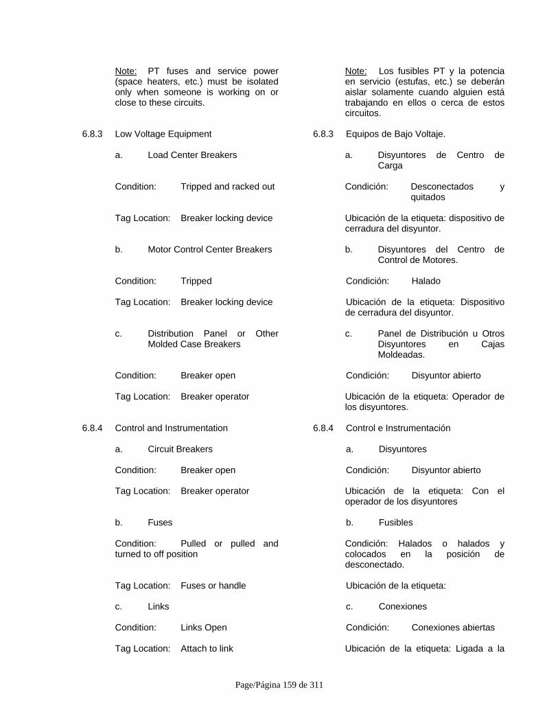
Page/Página 159 de 311
Note: PT fuses and service power(space heaters, etc.) must be isolatedonly when someone is working on orclose to these circuits.
Note: Los fusibles PT y la potenciaen servicio (estufas, etc.) se deberánaislar solamente cuando alguien estátrabajando en ellos o cerca de estoscircuitos.
6.8.3 Low Voltage Equipment 6.8.3 Equipos de Bajo Voltaje.
a. Load Center Breakers a. Disyuntores de Centro deCarga
Condition: Tripped and racked out Condición: Desconectados yquitados
Tag Location: Breaker locking device Ubicación de la etiqueta: dispositivo decerradura del disyuntor.
b. Motor Control Center Breakers b. Disyuntores del Centro deControl de Motores.
Condition: Tripped Condición: Halado
Tag Location: Breaker locking device Ubicación de la etiqueta: Dispositivode cerradura del disyuntor.
c. Distribution Panel or OtherMolded Case Breakers
c. Panel de Distribución u OtrosDisyuntores en CajasMoldeadas.
Condition: Breaker open Condición: Disyuntor abierto
Tag Location: Breaker operator Ubicación de la etiqueta: Operador delos disyuntores.
6.8.4 Control and Instrumentation 6.8.4 Control e Instrumentación
a. Circuit Breakers a. Disyuntores
Condition: Breaker open Condición: Disyuntor abierto
Tag Location: Breaker operator Ubicación de la etiqueta: Con eloperador de los disyuntores
b. Fuses b. Fusibles
Condition: Pulled or pulled andturned to off position
Condición: Halados o halados ycolocados en la posición dedesconectado.
Tag Location: Fuses or handle Ubicación de la etiqueta:
c. Links c. Conexiones
Condition: Links Open Condición: Conexiones abiertas
Tag Location: Attach to link Ubicación de la etiqueta: Ligada a la
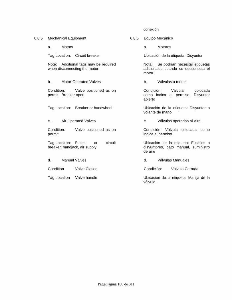
Page/Página 160 de 311
conexión
6.8.5 Mechanical Equipment 6.8.5 Equipo Mecánico
a. Motors a. Motores
Tag Location: Circuit breaker Ubicación de la etiqueta: Disyuntor
Note: Additional tags may be requiredwhen disconnecting the motor.
Nota: Se podrían necesitar etiquetasadicionales cuando se desconecta elmotor.
b. Motor-Operated Valves b. Válvulas a motor
Condition: Valve positioned as onpermit. Breaker open
Condición: Válvula colocadacomo indica el permiso. Disyuntorabierto
Tag Location: Breaker or handwheel Ubicación de la etiqueta: Disyuntor ovolante de mano
c. Air-Operated Valves c. Válvulas operadas al Aire.
Condition: Valve positioned as onpermit
Condición: Válvula colocada comoindica el permiso.
Tag Location: Fuses or circuitbreaker, handjack, air supply
Ubicación de la etiqueta: Fusibles odisyuntores, gato manual, suministrode aire
d. Manual Valves d. Válvulas Manuales
Condition Valve Closed Condición: Válvula Cerrada
Tag Location Valve handle Ubicación de la etiqueta: Manija de laválvula.

Page/Página 161 de 311
ATTACHMENT A-1SYSTEM AND EQUIPMENT SAFETY TAGGING/LOCKOUT
WORK PROCESS FLOW CHART
(Standard Process)
CompleteApplicable
Sections of thePermit [6.2.1]
PR
START
Verify Adequacy ofProposedProtective
Measures Prior toSigning Permit and
Submitting forApproval [6.2.2]
PR
IdentifySupplementalRequestors onPermit [6.2.3]
TA, PR
Assure that PermitRequestor isAuthorized to
make Request;Determine theType of SafetyBoundary and
RequiredProtective
Measures [6.2.4]
TA
Complete Permitand Associated
Safety Tags [6.2.5]
PR
Consult withResponsible
Equipment/SystemEngineer AboutPermit Request
[6.2.6]
TA, RE/SE
Verify Request;Approve Permit;
Give Required TagStubs, Locks, and
Keys to PermitRequestor [6.2.7,
6.2.11]
TA
ImplementSpecifiedProtective
Measures, HangSafety Tags, and
Place Locks[6.2.9]
PR, RE/SE
Return Keys forany Lockouts to
Tagging Authority[6.2.10]
PR
WORK PERFORMED ANDCOMPLETED
Note: Tagging Authority is to Notify Permit Requestor of any SupplementalRequestors Added to System after Approval [6.2.8]
Change toPermit (seeAttachment
A-2)
EmergencyClosure/Change(see Attachment
A-3)
Complete PermitClosure
(see AttachmentA-4)
Work Process TaskDescription
OrganizationalResponsibility
Legend:
Organizational Abbreviations:
PR = Permit RequestorSR = Supplemental RequestorTA = Tagging AuthorityRE/SE = Responsible Equipment/System EngineerPRC = Person Responsible for Change/ClosureSUPV = Supervisor of Unavailable PR or SRSM/SU = Site Manager/Startup Manager
Complete Permitand Associated
Safety Tags [6.2.5]
PR
Temporary Lift -If Necessary
[6.6.6}
PR, SR, TA,RE/SE

Page/Página 162 de 311
ATTACHMENT A-2SYSTEM AND EQUIPMENT SAFETY TAGGING/LOCKOUT
WORK PROCESS FLOW CHART
(Change to Existing Tagging Permit)
Determine Need toModify Boundaries
[6.3.1]
PR, SR
Review andConcur withProposed
Changes [6.3.1]
PR, TA
Modify Permit[6.3.1]
TA
EmergencyClosure/ChangeProcedure (seeAttachment A-3)
[6.3.4 b]
Complete SafetyTagging Permit
Closure(see Attachment
A-4)
ProtectionReduced?
Notify all Groupson Permit of
Change [6.3.2]
TA
Change Tags andSystem
Configuration[6.3.2]
TA
Verify NewBoundaries and
Tags [6.3.3]
PR, SR
Initial for Changes[6.3.3]
PR, SR
Notify all Groupsof Pending
Change [6.3.4]
TA
All RequestorsAvailable?
Release Permit bySigning Off [6.3.4 a]
PR, SR
Cease all Workwithin Scope ofPermit [6.3.4 a]
PR, SR
Change Tags andSystem
Configuration[6.3.4 c]
TA
Verify NewBoundaries and
Tags; Re-sign onPermit prior to
RecommencingWork [6.3.5]
PR, SR
NO
NO
YES
YES
Initiate Permit(see Attachment
A-1)
WORK PERFORMED ANDCOMPLETEDWork Process Task
Description
OrganizationalResponsibility
Legend:
Organizational Abbreviations:
PR = Permit RequestorSR = Supplemental RequestorTA = Tagging AuthorityRE/SE = Responsible Equipment/System EngineerPRC = Person Responsible for Change/ClosureSUPV = Supervisor of Unavailable PR or SRSM/SU = Site Manager/Startup Manager
Complete Permitand Associated
Safety Tags [6.2.5]
PR
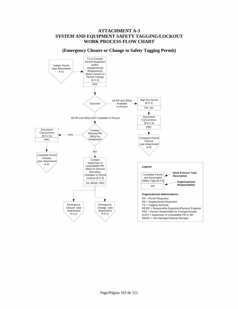
Page/Página 163 de 311
ATTACHMENT A-3SYSTEM AND EQUIPMENT SAFETY TAGGING/LOCKOUT
WORK PROCESS FLOW CHART
(Emergency Closure or Change to Safety Tagging Permit)
Outcome
DocumentConcurrence
[6.5.2 a]
PRC
ContactSupervisor of
Unavailable PR/SR(s) to Discuss
BoundaryChanges or Permit
Closure [6.5.3]
TA, RESE, PRC
Try to ContactPermit Requestor
and/orSupplementalRequestor(s)
about Closure orPermit Change
[6.5.2]
PRC
DocumentConcurrence
[6.5.2 a]
PRC
Sign the Permit[6.5.1]
PR, SR
Complete PermitClosure
(see AttachmentA-4)
All PR and SR(s)AvailableIn Person
ContactMissing PR/
SR(s) byTelephone?
All PR and SR(s) NOT Available in Person
Complete PermitClosure
(see AttachmentA-4)
YES
NO
EmergencyClosure (seeAttachment
A-3.1)
EmergencyChange (seeAttachment
A-3.1)
Initiate Permit(see Attachment
A-1)
Work Process TaskDescription
OrganizationalResponsibility
Legend:
Organizational Abbreviations:
PR = Permit RequestorSR = Supplemental RequestorTA = Tagging AuthorityRE/SE = Responsible Equipment/System EngineerPRC = Person Responsible for Change/ClosureSUPV = Supervisor of Unavailable PR or SRSM/SU = Site Manager/Startup Manager
Complete Permitand Associated
Safety Tags [6.2.5]
PR
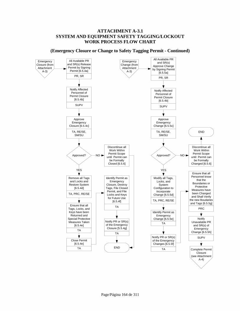
Page/Página 164 de 311
ATTACHMENT A-3.1SYSTEM AND EQUIPMENT SAFETY TAGGING/LOCKOUT
WORK PROCESS FLOW CHART
(Emergency Closure or Change to Safety Tagging Permit - Continued)
Approved?
EmergencyClosure (fromAttachment
A-3)
EmergencyChange (fromAttachment
A-3)
All Available PRand SR(s) ReleasePermit by Signing
Permit [6.5.4a]
PR, SR
All Available PRand SR(s)
Approve Changeby Signing Permit
[6.5.5a]
PR, SR
ApproveEmergency
Closure [6.5.4c]
TA, RE/SE,SM/SU
ApproveEmergency
Change [6.5.5c]
TA, RE/SE,SM/SU
NO Approved? NO
Remove all Tagsand Locks and
Restore System[6.5.4d]
TA, PRC, RE/SE
YES
Ensure that allTags, Locks, andKeys have been
Returned andSpecial ProtectiveMeasures Taken
[6.5.4e]
TA
Close Permit[6.5.4e]
TA
Identify Permit asEmergency
Closure, DestroyTags, File ClosedPermit, and FileLocks and Keysfor Future Use
[6.5.4f]
TA
Notify PR or SR(s)of the EmergencyClosure [5.5.4g]
TA
END
Modify all Tags,Locks, and
SystemConfiguration to
IncorporateChange [6.5.5d]
TA, PRC, RE/SE
YES
Identify Permit asEmergency
Change [6.5.5e]
TA
Notify PR or SR(s)of the EmergencyChanges [6.5.5f]
TA
Ensure that allPersonnel know
that theBoundaries or
ProtectiveMeasures havebeen Changedand Shall Verify
the new Boudariesand Tags [6.5.5g]
PRC
Notify AffectedPersonnel of
Permit Closure[6.5.4b]
SUPV
Notify AffectedPersonnel of
Permit Closure[6.5.4b]
SUPV
NotifyUnavailable PR
and SR(s) ofEmergency
Change [6.5.5h]
SUPV
Discontinue allWork Within
Permit Scopeuntil Permit can
be FormallyClosed [6.5.6]
Discontinue allWork Within
Permit Scopeuntil Permit can
be FormallyChanged [6.5.6]
Complete PermitClosure
(see AttachmentA-4)
END
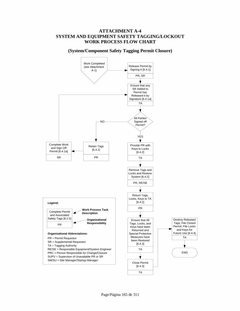
Page/Página 165 de 311
ATTACHMENT A-4SYSTEM AND EQUIPMENT SAFETY TAGGING/LOCKOUT
WORK PROCESS FLOW CHART
(System/Component Safety Tagging Permit Closure)
All PartiesSigned offPermit?
Retain Tags[6.4.1]
PR
Provide PR withKeys to Locks
[6.4.2]
TA
Remove Tags andLocks and Restore
System [6.4.2]
PR, RE/SE
Release Permit bySigning It [6.4.1]
PR, SR
YES
Return Tags,Locks, Keys to TA
[6.4.2]
PR
Close Permit[6.4.3]
TA
Destroy ReleasedTags; File ClosedPermit; File Locks
and Keys forFuture Use [6.4.4]
TA
END
NO
Ensure that AllTags, Locks, andKeys have been
Returned andSpecial Protective
Measures havebeen Restored
[6.4.3]
TA
Work Process TaskDescription
OrganizationalResponsibility
Legend:
Organizational Abbreviations:
PR = Permit RequestorSR = Supplemental RequestorTA = Tagging AuthorityRE/SE = Responsible Equipment/System EngineerPRC = Person Responsible for Change/ClosureSUPV = Supervisor of Unavailable PR or SRSM/SU = Site Manager/Startup Manager
Complete Permitand Associated
Safety Tags [6.2.5]
PR
Work Completed(see Attachment
A-1)
SR
Complete Workand Sign Off
Permit [6.4.1a]
Ensure that anySR Added toPermit has
Released it bySignature [6.4.1a]
TA

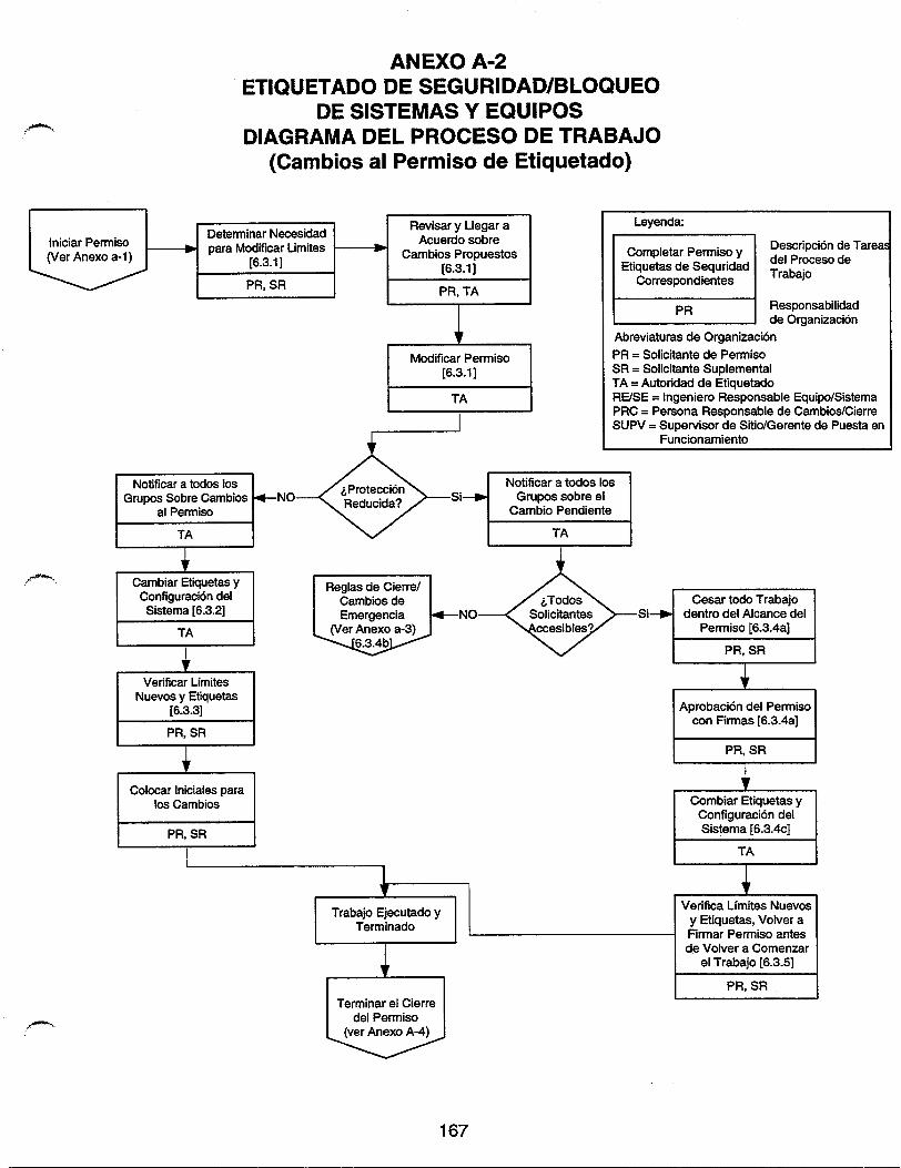

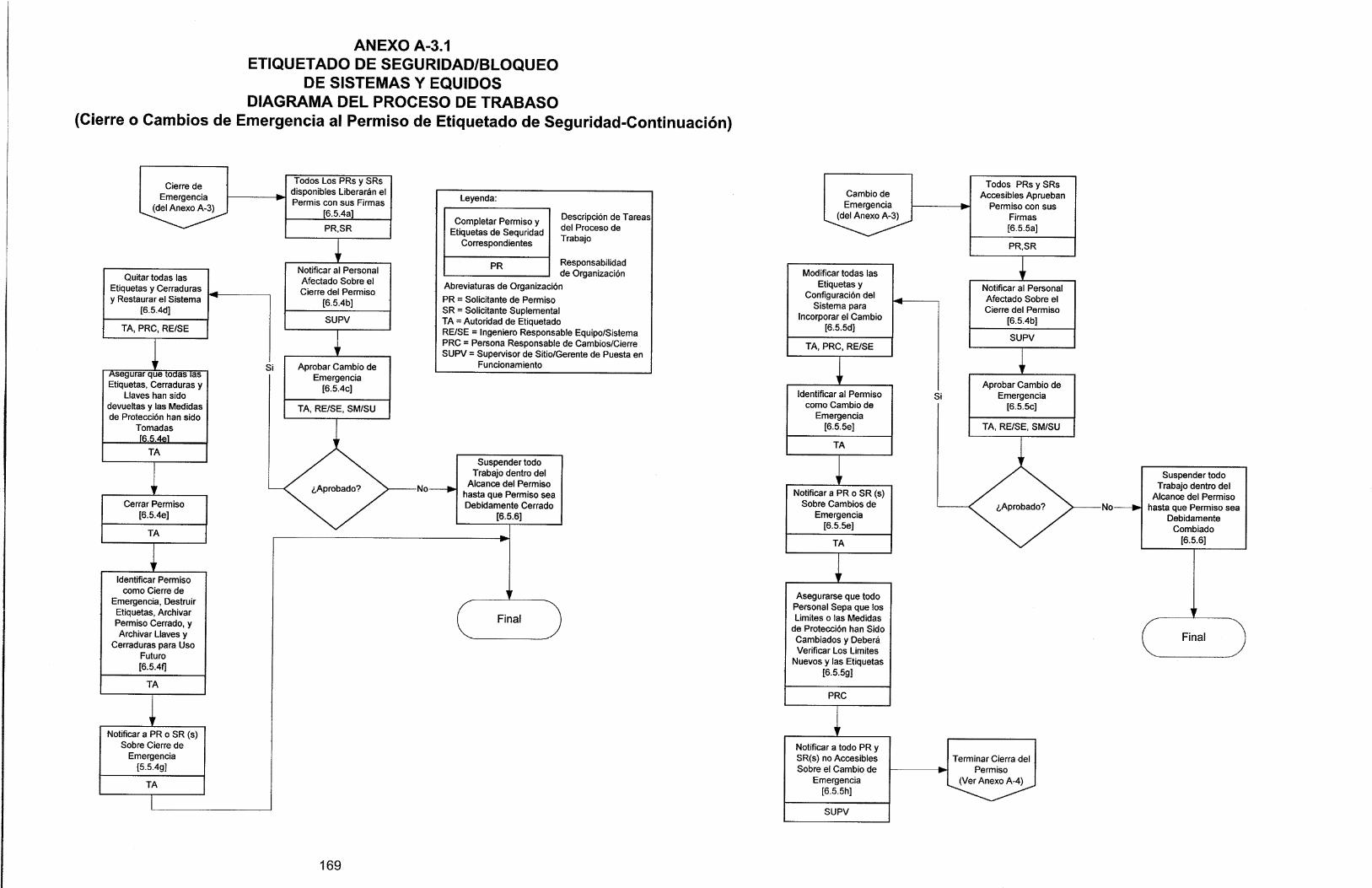
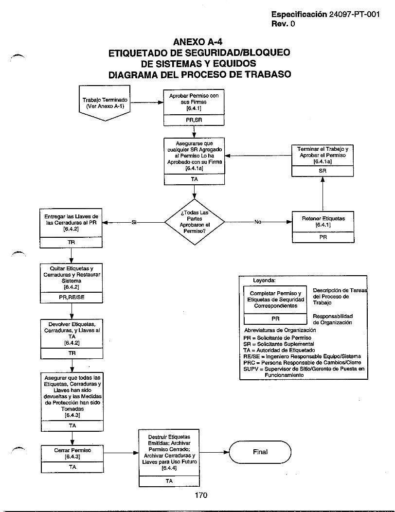
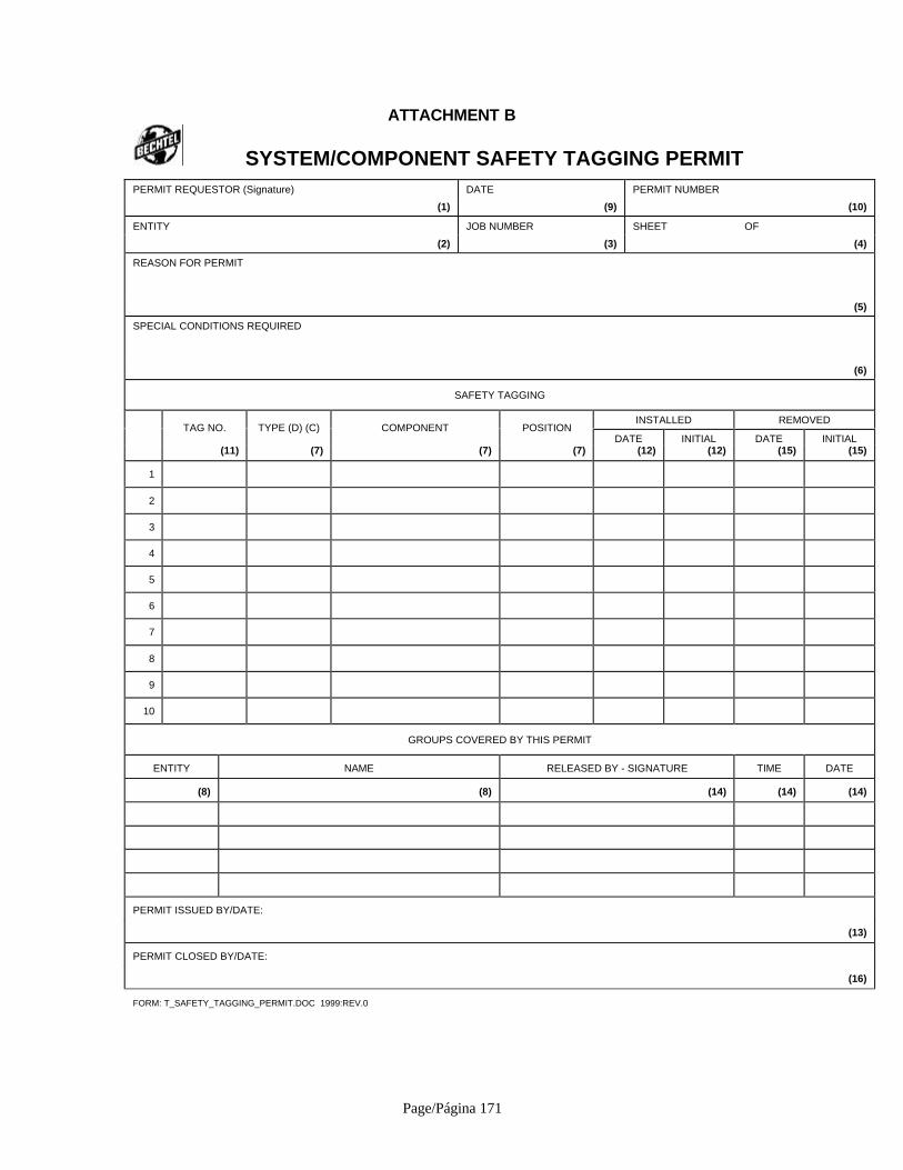
Page/Página 171
ATTACHMENT B
SYSTEM/COMPONENT SAFETY TAGGING PERMITPERMIT REQUESTOR (Signature) DATE PERMIT NUMBER
(1) (9) (10)
ENTITY JOB NUMBER SHEET OF
(2) (3) (4)
REASON FOR PERMIT
(5)
SPECIAL CONDITIONS REQUIRED
(6)
SAFETY TAGGING
INSTALLED REMOVEDTAG NO. TYPE (D) (C) COMPONENT POSITION
DATE INITIAL DATE INITIAL(11) (7) (7) (7) (12) (12) (15) (15)
1
2
3
4
5
6
7
8
9
10
GROUPS COVERED BY THIS PERMIT
ENTITY NAME RELEASED BY - SIGNATURE TIME DATE
(8) (8) (14) (14) (14)
PERMIT ISSUED BY/DATE:
(13)
PERMIT CLOSED BY/DATE:
(16)
FORM: T_SAFETY_TAGGING_PERMIT.DOC 1999:REV.0

Page/Página 172
ANEXO B
PERMISO DE ETIQUETADO DE SEGURIDAD DE SISTEMAS/COMPONENTES
SOLICITANTE DEL PERMISO (Firma) FECHA NUMERO DE PERMISO
(1) (9) (10)
DEPARTAMENTO NUMERO DE TRABAJO HOJA DE
(2) (3) (4)
RAZON DEL PERMISO
(5)
CONDITIONS ESPECIALES REQUERIDAS
(6)
ETIQUETADO DE SEGURIDAD
INSTALADO QUITADONo deETIQUETA. TIPO (D) (C) COMPONENTE POSICION
FECHA INICIAL FECHA INICIAL(11) (7) (7) (7) (12) (12) (15) (15)
1
2
3
4
5
6
7
8
9
10
GRUPOS CUBIERTOS POR ESTE PERMISO
ENTIDAD NOMBRE LIBERADO POR - FIRMA HORA FECHA
(8) (8) (14) (14) (14)
PERMISO EMITIDO POR/FECHA:
(13)
PERMISO CANCELADO POR/FECHA:
(16)
FORM: T_SAFETY_TAGGING_PERMIT.DOC 1999:REV.0
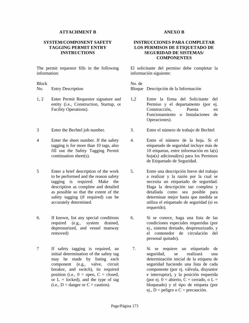
Page/Página 173
ATTACHMENT B ANEXO B
SYSTEM/COMPONENT SAFETYTAGGING PERMIT ENTRY
INSTRUCTIONS
INSTRUCCIONES PARA COMPLETARLOS PERMISOS DE ETIQUETADO DE
SEGURIDAD DE SISTEMAS/COMPONENTES
The permit requestor fills in the followinginformation:
El solicitante del permiso debe completar lainformación siguiente:
BlockNo. Entry Description
No. deBloque Descripción de la Información
1, 2 Enter Permit Requestor signature andentity (i.e., Construction, Startup, orFacility Operations).
1,2 Entre la firma del Solicitante delPermiso y el departamento (por ej.Construcción, Puesta enFuncionamiento o Instalaciones deOperaciones).
3 Enter the Bechtel job number. 3. Entre el número de trabajo de Bechtel
4 Enter the sheet number. If the safetytagging is for more than 10 tags, alsofill out the Safety Tagging Permitcontinuation sheet(s).
4. Entre el número de la hoja. Si eletiquetado de seguridad incluye más de10 etiquetas, entre información en la(s)hoja(s) adicional(es) para los Permisosde Etiquetado de Seguridad.
5 Enter a brief description of the workto be performed and the reason safetytagging is required. Make thedescription as complete and detailedas possible so that the extent of thesafety tagging (if required) can beaccurately determined.
5. Entre una descripción breve del trabajoa realizar y la razón por la cual senecesita un etiquetado de seguridad.Haga la descripción tan completa ydetallada como sea posible paradeterminar mejor hasta que medida seutiliza el etiquetado de seguridad (si esrequerido).
6. If known, list any special conditionsrequired (e.g., system drained,depressurized, and vessel manwayremoved)
6. Si se conoce, haga una lista de lascondiciones especiales requeridas (porej., sistema drenado, despresurizado, yel contenedor de circulación delpersonal quitado).
7 If safety tagging is required, aninitial determination of the safety tagmay be made by listing eachcomponent (e.g., valve, circuitbreaker, and switch), its requiredposition (i.e., 0 = open, C = closed,or L = locked), and the type of tag(i.e., D = danger or C = caution).
7. Si se requiere un etiquetado deseguridad, se realizará unadeterminación inicial de la etiqueta deseguridad haciendo una lista de cadacomponente (por ej. válvula, disyuntore interruptor), y la posición requerida(por ej. 0 = abierto, C = cerrado, o L =bloqueado) y el tipo de etiqueta (porej., D = peligro o C = precaución.
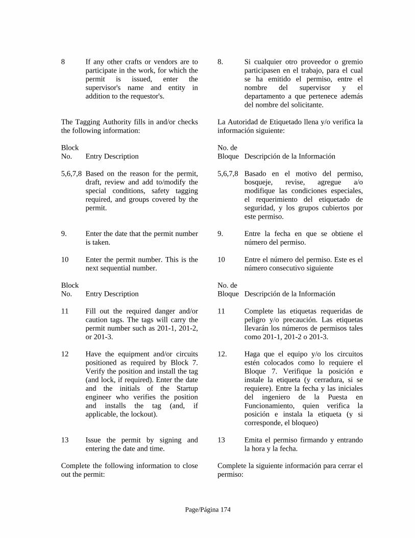
Page/Página 174
8 If any other crafts or vendors are toparticipate in the work, for which thepermit is issued, enter thesupervisor's name and entity inaddition to the requestor's.
8. Si cualquier otro proveedor o gremioparticipasen en el trabajo, para el cualse ha emitido el permiso, entre elnombre del supervisor y eldepartamento a que pertenece ademásdel nombre del solicitante.
The Tagging Authority fills in and/or checksthe following information:
La Autoridad de Etiquetado llena y/o verifica lainformación siguiente:
BlockNo. Entry Description
No. deBloque Descripción de la Información
5,6,7,8 Based on the reason for the permit,draft, review and add to/modify thespecial conditions, safety taggingrequired, and groups covered by thepermit.
5,6,7,8 Basado en el motivo del permiso,bosqueje, revise, agregue a/omodifique las condiciones especiales,el requerimiento del etiquetado deseguridad, y los grupos cubiertos poreste permiso.
9. Enter the date that the permit numberis taken.
9. Entre la fecha en que se obtiene elnúmero del permiso.
10 Enter the permit number. This is thenext sequential number.
10 Entre el número del permiso. Este es elnúmero consecutivo siguiente
BlockNo. Entry Description
No. deBloque Descripción de la Información
11 Fill out the required danger and/orcaution tags. The tags will carry thepermit number such as 201-1, 201-2,or 201-3.
11 Complete las etiquetas requeridas depeligro y/o precaución. Las etiquetasllevarán los números de permisos talescomo 201-1, 201-2 o 201-3.
12 Have the equipment and/or circuitspositioned as required by Block 7.Verify the position and install the tag(and lock, if required). Enter the dateand the initials of the Startupengineer who verifies the positionand installs the tag (and, ifapplicable, the lockout).
12. Haga que el equipo y/o los circuitosestén colocados como lo requiere elBloque 7. Verifique la posición einstale la etiqueta (y cerradura, si serequiere). Entre la fecha y las inicialesdel ingeniero de la Puesta enFuncionamiento, quien verifica laposición e instala la etiqueta (y sicorresponde, el bloqueo)
13 Issue the permit by signing andentering the date and time.
13 Emita el permiso firmando y entrandola hora y la fecha.
Complete the following information to closeout the permit:
Complete la siguiente información para cerrar elpermiso:

Page/Página 175
BlockNo. Entry Description
No. deBloque Descripción de la Información.
14 As each group completes its workunder the permit, a signature, timeand date are required indicating thatthe group has released itself from thepermit coverage.
14. A medida que cada grupo completa sutrabajo según el permiso, se necesitaráuna firma, hora y fecha que indiquenque el grupo se libera de la coberturadel permiso.
15 After all entities have released Block14 and the safety tagging is no longerrequired (partially or totally), havethe construction engineer or testengineer remove each tag and enterthe date and his/her initials. If lockswere installed, the initials also verifythat the locks were removed.
15. Después de que todas las entidadeshayan liberado el Bloque No 14 y eletiquetado de seguridad ya no serequiera (parcial o totalmente), elingeniero de construcción o elingeniero de pruebas deberá quitarcada etiqueta y entrar la fecha y susiniciales. Si se hubiesen instaladocerraduras, la iniciales tambiénverifican que se han quitado lascerraduras.
16 After all work is complete, theTagging Authority closes the permitby signing and entering the date andtime.
16. Después de que todo el trabajo se hacompletado, la Autoridad deEtiquetado cancelará el permiso con laentrada de una firma, la hora y lafecha.
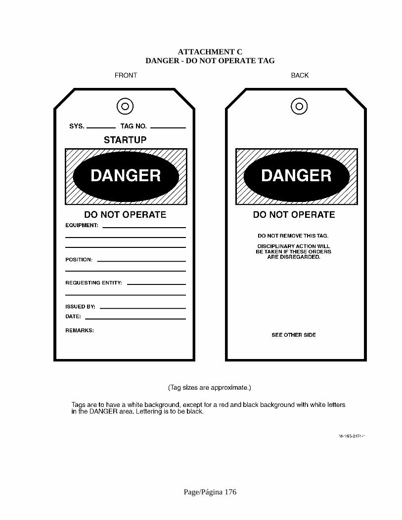
Page/Página 176
ATTACHMENT CDANGER - DO NOT OPERATE TAG
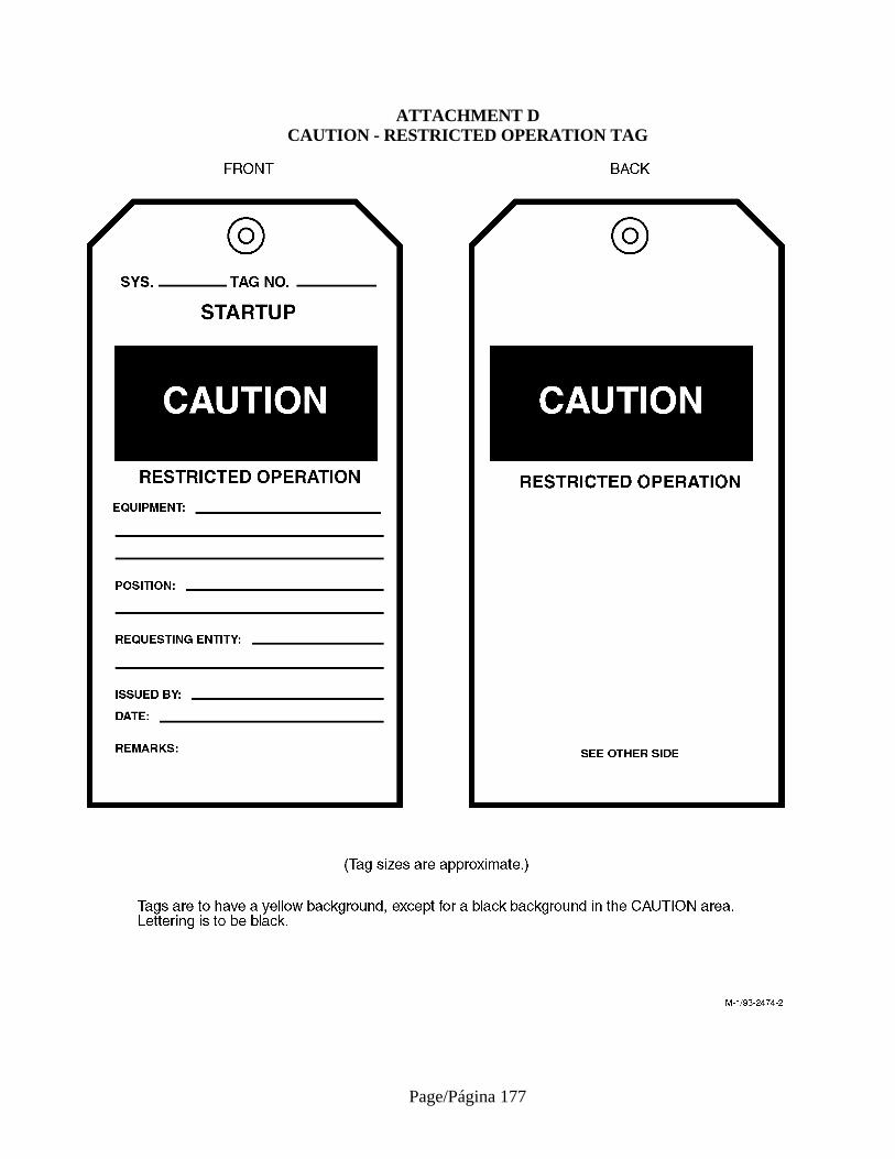
Page/Página 177
ATTACHMENT DCAUTION - RESTRICTED OPERATION TAG

Page/Página 178
ANEXO CPELIGRO – ETIQUETA DE NO OPERAR

Page/Página 179
ANEXO DPRECAUCION – ETIQUETA DE OPERACION RESTRINGIDA
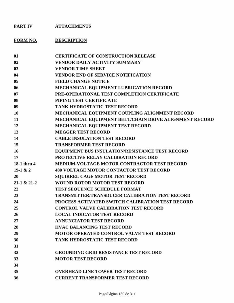
Page/Página 180 de 311
PART IV ATTACHMENTS
FORM NO. DESCRIPTION
01 CERTIFICATE OF CONSTRUCTION RELEASE02 VENDOR DAILY ACTIVITY SUMMARY03 VENDOR TIME SHEET04 VENDOR END OF SERVICE NOTIFICATION05 FIELD CHANGE NOTICE06 MECHANICAL EQUIPMENT LUBRICATION RECORD07 PRE-OPERATIONAL TEST COMPLETION CERTIFICATE08 PIPING TEST CERTIFICATE09 TANK HYDROSTATIC TEST RECORD10 MECHANICAL EQUIPMENT COUPLING ALIGNMENT RECORD11 MECHANICAL EQUIPMENT BELT/CHAIN DRIVE ALIGNMENT RECORD12 MECHANICAL EQUIPMENT TEST RECORD13 MEGGER TEST RECORD14 CABLE INSULATION TEST RECORD15 TRANSFORMER TEST RECORD16 EQUIPMENT BUS INSULATION/RESISTANCE TEST RECORD17 PROTECTIVE RELAY CALIBRATION RECORD18-1 thru 4 MEDIUM-VOLTAGE MOTOR CONTRACTOR TEST RECORD19-1 & 2 480 VOLTAGE MOTOR CONTACTOR TEST RECORD20 SQUIRREL CAGE MOTOR TEST RECORD21-1 & 21-2 WOUND ROTOR MOTOR TEST RECORD22 TEST SEQUENCE SCHEDULE FORMAT23 TRANSMITTER/TRANSDUCER CALIBRATION TEST RECORD24 PROCESS ACTIVATED SWITCH CALIBRATION TEST RECORD25 CONTROL VALVE CALIBRATION TEST RECORD26 LOCAL INDICATOR TEST RECORD27 ANNUNCIATOR TEST RECORD28 HVAC BALANCING TEST RECORD29 MOTOR OPERATED CONTROL VALVE TEST RECORD30 TANK HYDROSTATIC TEST RECORD3132 GROUNDING GRID RESISTANCE TEST RECORD33 MOTOR TEST RECORD3435 OVERHEAD LINE TOWER TEST RECORD36 CURRENT TRANSFORMER TEST RECORD
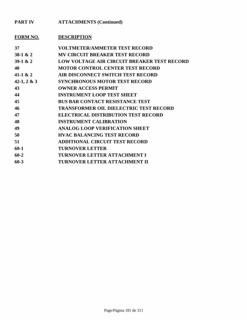
Page/Página 181 de 311
PART IV ATTACHMENTS (Continued)
FORM NO. DESCRIPTION
37 VOLTMETER/AMMETER TEST RECORD38-1 & 2 MV CIRCUIT BREAKER TEST RECORD39-1 & 2 LOW VOLTAGE AIR CIRCUIT BREAKER TEST RECORD40 MOTOR CONTROL CENTER TEST RECORD41-1 & 2 AIR DISCONNECT SWITCH TEST RECORD42-1, 2 & 3 SYNCHRONOUS MOTOR TEST RECORD43 OWNER ACCESS PERMIT44 INSTRUMENT LOOP TEST SHEET45 BUS BAR CONTACT RESISTANCE TEST46 TRANSFORMER OIL DIELECTRIC TEST RECORD47 ELECTRICAL DISTRIBUTION TEST RECORD48 INSTRUMENT CALIBRATION49 ANALOG LOOP VERIFICATION SHEET50 HVAC BALANCING TEST RECORD51 ADDITIONAL CIRCUIT TEST RECORD60-1 TURNOVER LETTER60-2 TURNOVER LETTER ATTACHMENT I60-3 TURNOVER LETTER ATTACHMENT II
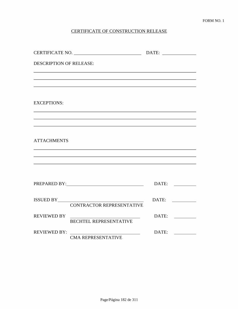
Page/Página 182 de 311
FORM NO. 1
CERTIFICATE OF CONSTRUCTION RELEASE
CERTIFICATE NO. DATE:
DESCRIPTION OF RELEASE:
EXCEPTIONS:
ATTACHMENTS
PREPARED BY: DATE:
ISSUED BY DATE: CONTRACTOR REPRESENTATIVE
REVIEWED BY DATE: BECHTEL REPRESENTATIVE
REVIEWED BY: DATE: CMA REPRESENTATIVE
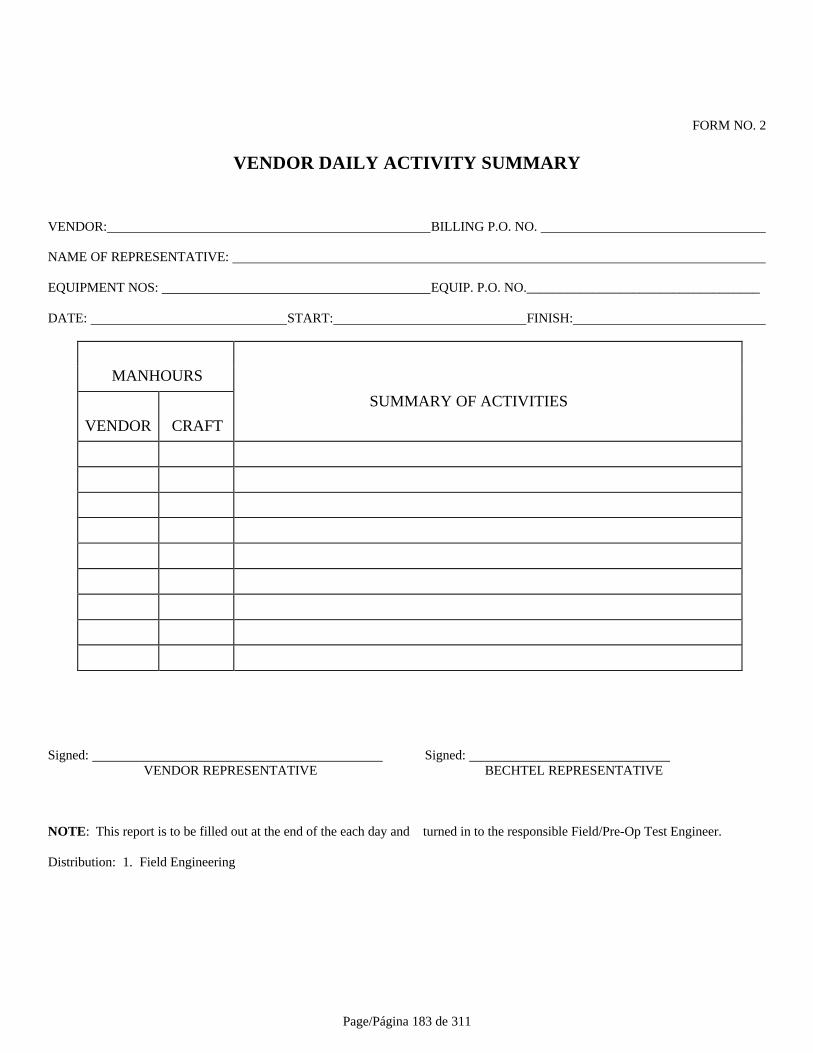
Page/Página 183 de 311
FORM NO. 2
VENDOR DAILY ACTIVITY SUMMARY
VENDOR: BILLING P.O. NO.
NAME OF REPRESENTATIVE:
EQUIPMENT NOS: EQUIP. P.O. NO.___________________________________
DATE: START: FINISH:
MANHOURS
SUMMARY OF ACTIVITIES
VENDOR CRAFT
Signed: Signed: VENDOR REPRESENTATIVE BECHTEL REPRESENTATIVE
NOTE: This report is to be filled out at the end of the each day and turned in to the responsible Field/Pre-Op Test Engineer.
Distribution: 1. Field Engineering
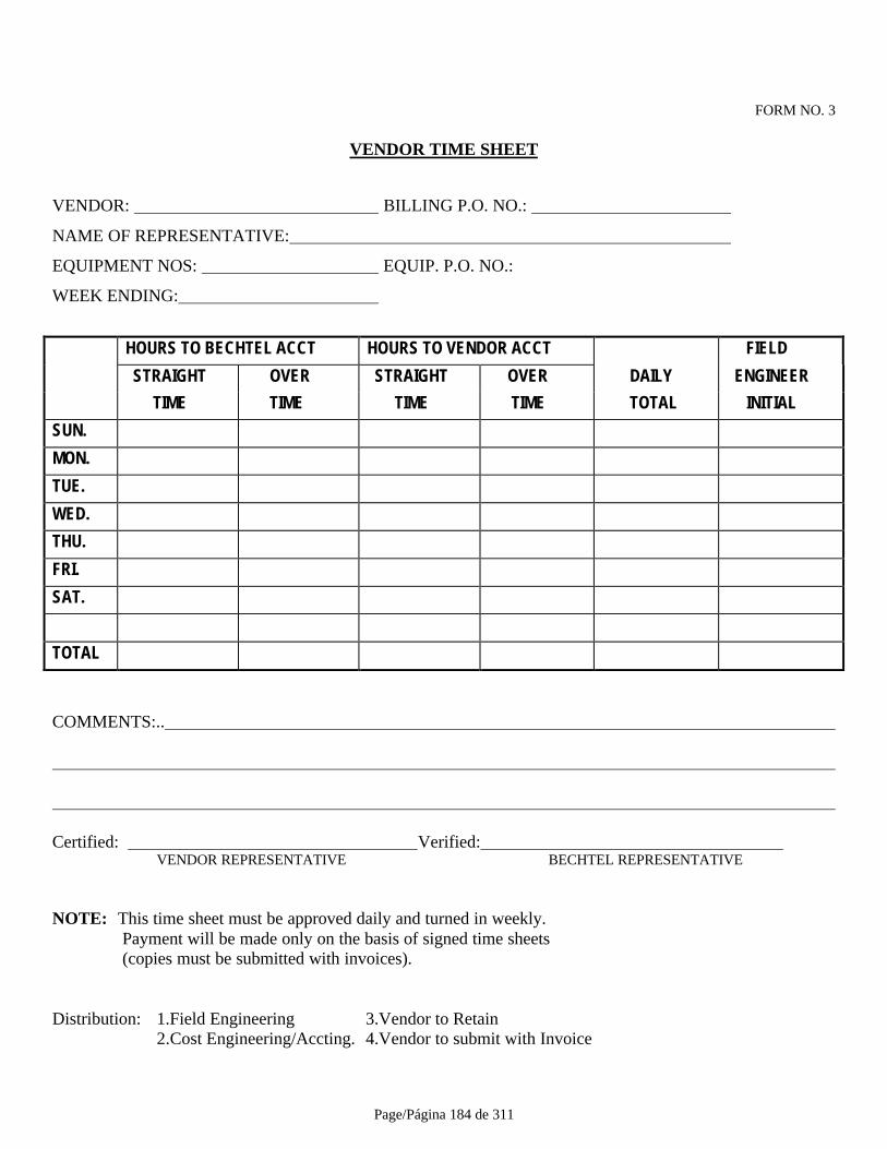
Page/Página 184 de 311
FORM NO. 3
VENDOR TIME SHEET
VENDOR: BILLING P.O. NO.:
NAME OF REPRESENTATIVE:
EQUIPMENT NOS: EQUIP. P.O. NO.:
WEEK ENDING:
HOURS TO BECHTEL ACCT HOURS TO VENDOR ACCT FIELD
STRAIGHT OVER STRAIGHT OVER DAILY ENGINEER
TIME TIME TIME TIME TOTAL INITIAL
SUN.
MON.
TUE.
WED.
THU.
FRI.
SAT.
TOTAL
COMMENTS:..
Certified: Verified: VENDOR REPRESENTATIVE BECHTEL REPRESENTATIVE
NOTE: This time sheet must be approved daily and turned in weekly. Payment will be made only on the basis of signed time sheets (copies must be submitted with invoices).
Distribution: 1.Field Engineering 3.Vendor to Retain 2.Cost Engineering/Accting. 4.Vendor to submit with Invoice
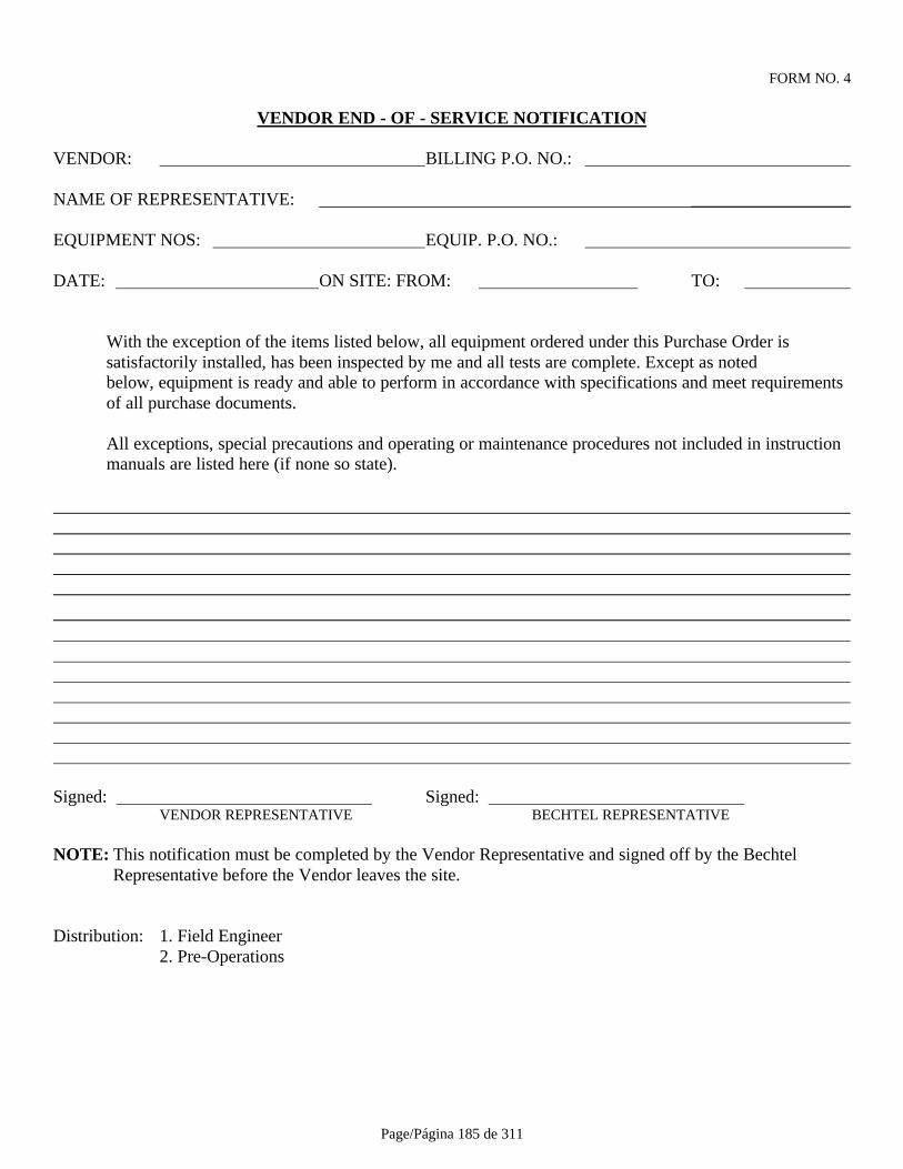
Page/Página 185 de 311
FORM NO. 4
VENDOR END - OF - SERVICE NOTIFICATION
VENDOR: BILLING P.O. NO.:
NAME OF REPRESENTATIVE: __________________
EQUIPMENT NOS: EQUIP. P.O. NO.:
DATE: ON SITE: FROM: TO:
With the exception of the items listed below, all equipment ordered under this Purchase Order issatisfactorily installed, has been inspected by me and all tests are complete. Except as notedbelow, equipment is ready and able to perform in accordance with specifications and meet requirementsof all purchase documents.
All exceptions, special precautions and operating or maintenance procedures not included in instruction manuals are listed here (if none so state).
Signed: Signed: VENDOR REPRESENTATIVE BECHTEL REPRESENTATIVE
NOTE: This notification must be completed by the Vendor Representative and signed off by the BechtelRepresentative before the Vendor leaves the site.
Distribution: 1. Field Engineer2. Pre-Operations
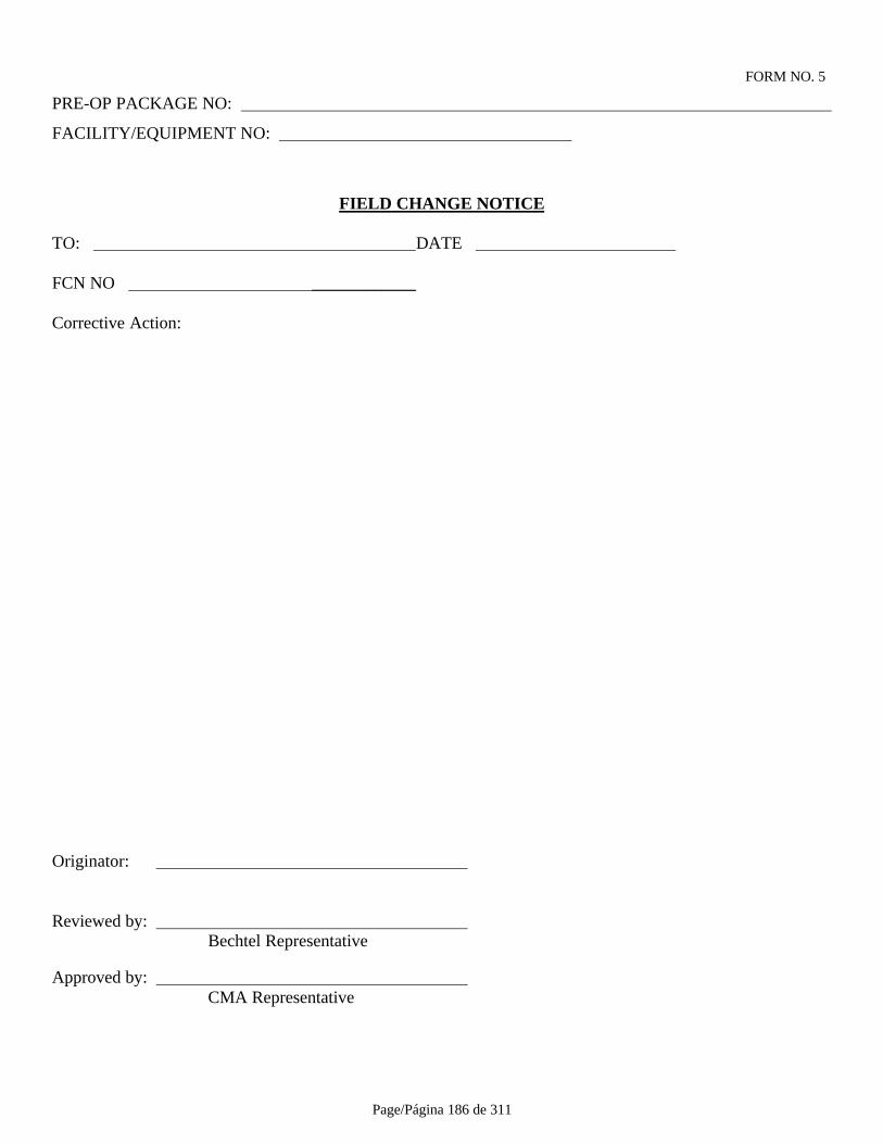
Page/Página 186 de 311
FORM NO. 5
PRE-OP PACKAGE NO:
FACILITY/EQUIPMENT NO:
FIELD CHANGE NOTICE
TO: DATE
FCN NO ____________
Corrective Action:
Originator:
Reviewed by: Bechtel Representative
Approved by: CMA Representative

Page/Página 187 de 311
FORM NO. 6PRE-OP PACKAGE NO:
FACILITY/EQUIPMENT NO.
MECHANICAL EQUIPMENT LUBRICATION RECORD
Equipment No.:
PART QTYLUBED TYPE ADDED LUBE
OR OF OR TAGCHECKING LUBRICATION PRE-LUBED NO. DATE SIGN
SUBMITTED: __ DATE: CONTRACTOR REPRESENTATIVE
REVIEWED: _______________________________ DATE BECHTEL REPRESENTATIVE
REVIEWED: _________________________________ DATE: OWNER REPRESENTATIVE
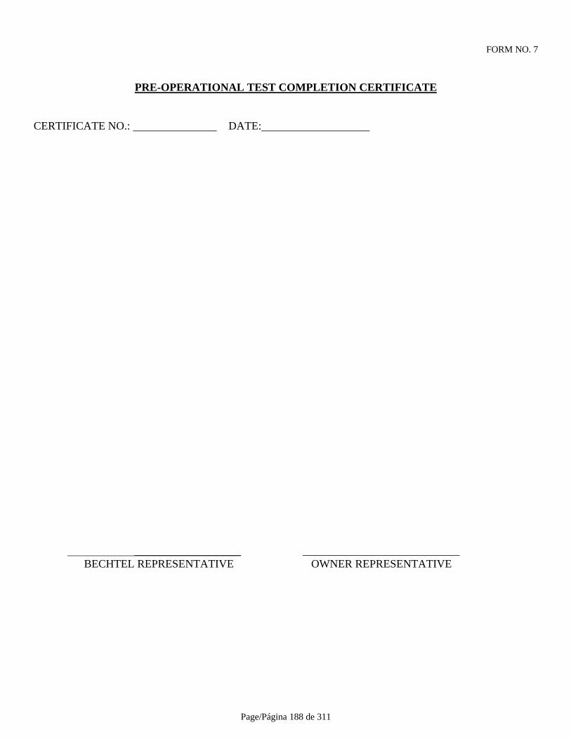
Page/Página 188 de 311
FORM NO. 7
PRE-OPERATIONAL TEST COMPLETION CERTIFICATE
CERTIFICATE NO.: DATE:
___________________ ____________________________BECHTEL REPRESENTATIVE OWNER REPRESENTATIVE
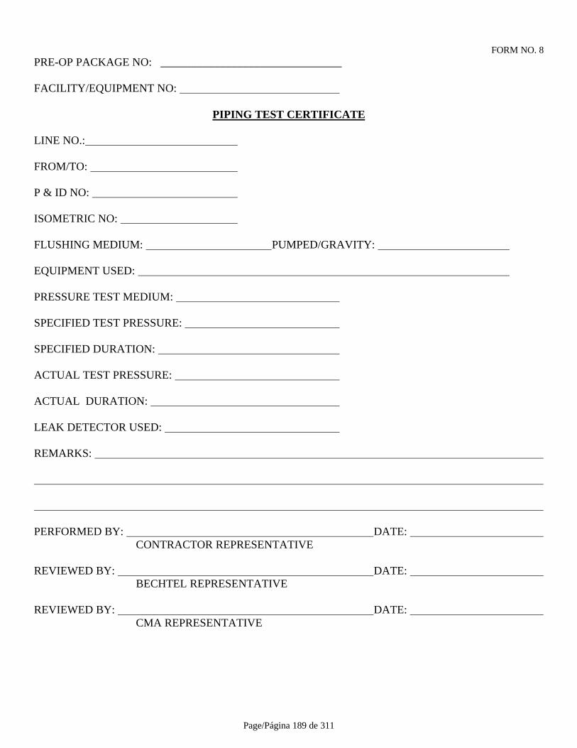
Page/Página 189 de 311
FORM NO. 8PRE-OP PACKAGE NO: ________________________________
FACILITY/EQUIPMENT NO:
PIPING TEST CERTIFICATE
LINE NO.:
FROM/TO:
P & ID NO:
ISOMETRIC NO:
FLUSHING MEDIUM: PUMPED/GRAVITY:
EQUIPMENT USED:
PRESSURE TEST MEDIUM:
SPECIFIED TEST PRESSURE:
SPECIFIED DURATION:
ACTUAL TEST PRESSURE:
ACTUAL DURATION:
LEAK DETECTOR USED:
REMARKS:
PERFORMED BY: DATE: CONTRACTOR REPRESENTATIVE
REVIEWED BY: DATE: BECHTEL REPRESENTATIVE
REVIEWED BY: DATE: CMA REPRESENTATIVE

Page/Página 190 de 311
FORM NO. 9PRE-OP PACKAGE NO :
FACILITY/EQUIPMENT NO:
TANK HYDROSTATIC TEST RECORD
Test Medium: Pressure: :
Test Results:
Remarks:
PERFORMED BY: DATE: CONTRACTOR REPRESENTATIVE
REVIEWED BY: DATE: BECHTEL REPRESENTATIVE
REVIEWED BY: DATE: CMA REPRESENTATIVE

Page/Página 191 de 311
FORM NO.10PRE-OP PACKAGE NO:
FACILITY EQUIPMENT NO:
MECHANICAL EQUIPMENT COUPLING ALIGNMENT RECORD
COUPLING MAKE & SIZE:
COUPLING GAP (SPECIFIED): (ACTUAL):
COUPLING LOCATED BETWEEN DRIVER:
DRIVEN:
REFER TO SPECIFICATION:
PARALLEL MISALIGNMENT ANGULAR REALIGNMENT
0°:. 0°:
90°: 90°:
180°: 180°:
270°: 270°:
Remarks:
PERFORMED BY : DATE: CONTRACTOR REPRESENTATIVE
REVIEWED BY: DATE: BECHTEL REPRESENTATIVE
REVIEWED BY: DATE: CMA REPRESENTATIVE
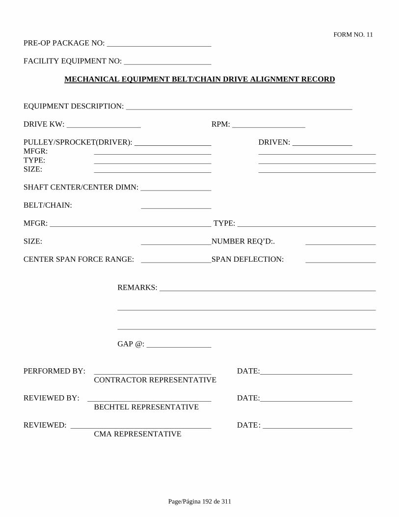
Page/Página 192 de 311
FORM NO. 11PRE-OP PACKAGE NO:
FACILITY EQUIPMENT NO:
MECHANICAL EQUIPMENT BELT/CHAIN DRIVE ALIGNMENT RECORD
EQUIPMENT DESCRIPTION:
DRIVE KW: RPM:
PULLEY/SPROCKET(DRIVER): DRIVEN: MFGR: TYPE: SIZE:
SHAFT CENTER/CENTER DIMN:
BELT/CHAIN:
MFGR: TYPE:
SIZE: NUMBER REQ’D:.
CENTER SPAN FORCE RANGE: SPAN DEFLECTION:
REMARKS:
GAP @:
PERFORMED BY: DATE: CONTRACTOR REPRESENTATIVE
REVIEWED BY: DATE: BECHTEL REPRESENTATIVE
REVIEWED: DATE: CMA REPRESENTATIVE
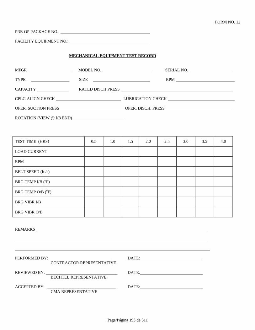
Page/Página 193 de 311
FORM NO. 12
PRE-OP PACKAGE NO.:
FACILITY EQUIPMENT NO.:
MECHANICAL EQUIPMENT TEST RECORD
MFGR MODEL NO. SERIAL NO.
TYPE SIZE RPM
CAPACITY RATED DISCH PRESS
CPLG ALIGN CHECK LUBRICATION CHECK
OPER. SUCTION PRESS OPER. DISCH. PRESS
ROTATION (VIEW @ I/B END)
TEST TIME (HRS) 0.5 1.0 1.5 2.0 2.5 3.0 3.5 4.0
LOAD CURRENT
RPM
BELT SPEED (ft./s)
BRG TEMP I/B (oF)
BRG TEMP O/B (oF)
BRG VIBR I/B
BRG VIBR O/B
REMARKS
PERFORMED BY: DATE: CONTRACTOR REPRESENTATIVE
REVIEWED BY: DATE: BECHTEL REPRESENTATIVE
ACCEPTED BY: DATE: CMA REPRESENTATIVE
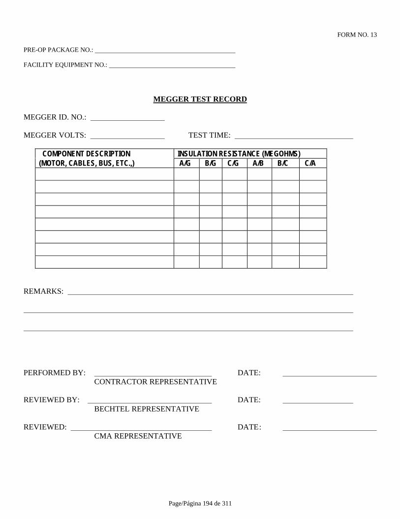
Page/Página 194 de 311
FORM NO. 13
PRE-OP PACKAGE NO.:
FACILITY EQUIPMENT NO.:
MEGGER TEST RECORD
MEGGER ID. NO.:
MEGGER VOLTS: TEST TIME:
COMPONENT DESCRIPTION INSULATION RESISTANCE (MEGOHMS)(MOTOR, CABLES, BUS, ETC.,) A/G B/G C/G A/B B/C C/A
REMARKS:
PERFORMED BY: DATE: CONTRACTOR REPRESENTATIVE
REVIEWED BY: DATE: BECHTEL REPRESENTATIVE
REVIEWED: DATE: CMA REPRESENTATIVE
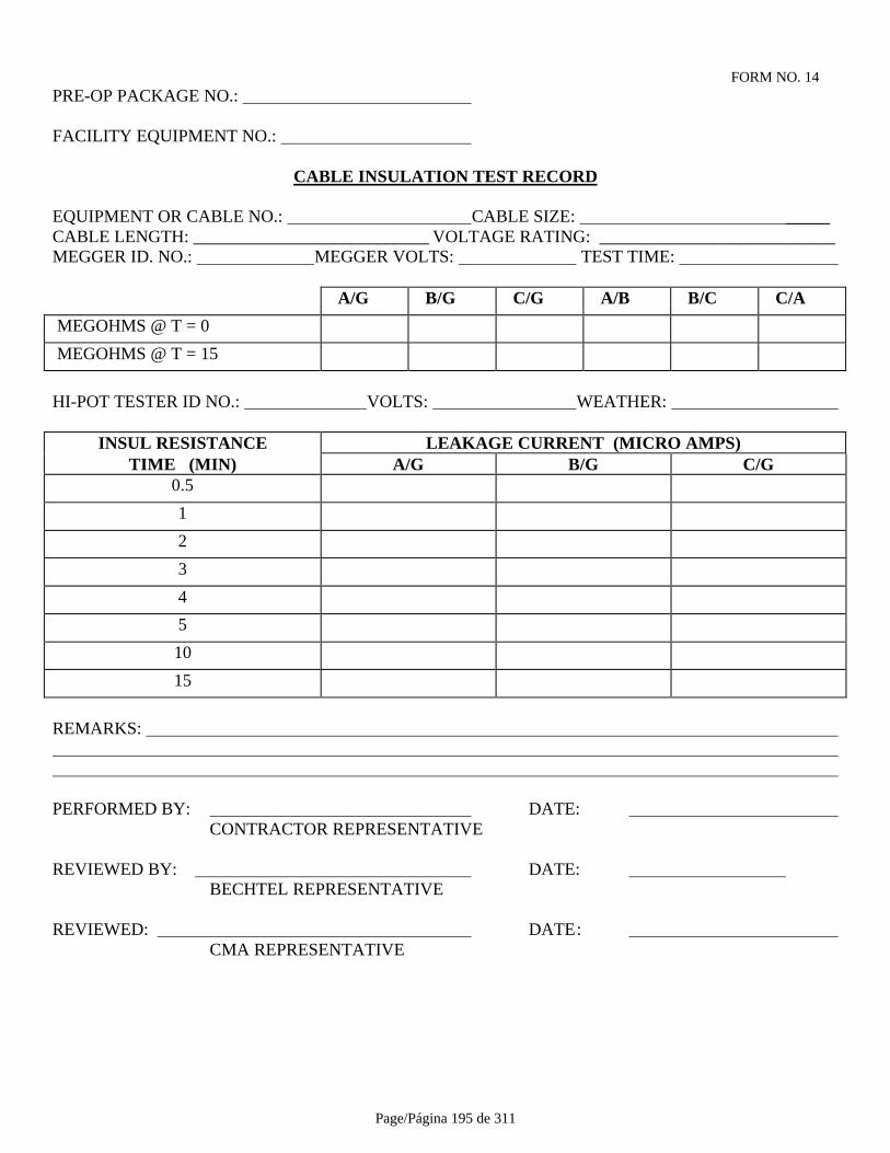
Page/Página 195 de 311
FORM NO. 14PRE-OP PACKAGE NO.:
FACILITY EQUIPMENT NO.:
CABLE INSULATION TEST RECORD
EQUIPMENT OR CABLE NO.: CABLE SIZE: _____CABLE LENGTH: ___________________________ VOLTAGE RATING: ___________________________MEGGER ID. NO.: MEGGER VOLTS: TEST TIME:
A/G B/G C/G A/B B/C C/A
MEGOHMS @ T = 0
MEGOHMS @ T = 15
HI-POT TESTER ID NO.: VOLTS: WEATHER:
INSUL RESISTANCE LEAKAGE CURRENT (MICRO AMPS)TIME (MIN) A/G B/G C/G
0.5
1
2
3
4
5
10
15
REMARKS:
PERFORMED BY: DATE: CONTRACTOR REPRESENTATIVE
REVIEWED BY: DATE: BECHTEL REPRESENTATIVE
REVIEWED: DATE: CMA REPRESENTATIVE
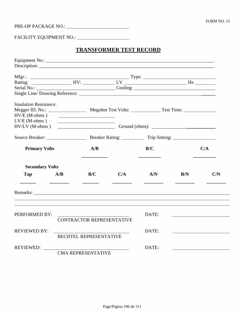
Page/Página 196 de 311
FORM NO. 15PRE-OP PACKAGE NO.:
FACILITY EQUIPMENT NO.:
TRANSFORMER TEST RECORD
Equipment No.: ______________________________________________________________________Description: _________________________________________________________________________
Mfgr.: Type: Rating: HV: LV Hz Serial No.: Cooling: Single Line/ Drawing Reference: ______
Insulation Resistance:Megger ID. No.: Megohm Test Volts: Test Time: HV/E (M-ohms ) LV/E (M-ohms ) HV/LV (M-ohms ) Ground (ohms): ____________
Source Breaker: Breaker Rating: Trip Setting:
Primary Volts A/B B/C C/A________ _______ _______
Secondary Volts
Tap A/B B/C C/A A/N B/N C/N_____ ______ _____ ______ ______ ______ ______
Remarks:
PERFORMED BY: DATE: CONTRACTOR REPRESENTATIVE
REVIEWED BY: DATE: BECHTEL REPRESENTATIVE
REVIEWED: DATE: CMA REPRESENTATIVE
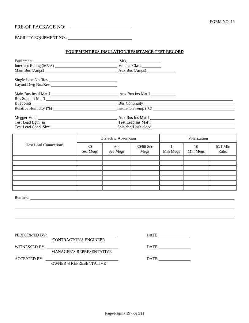
Page/Página 197 de 311
FORM NO. 16PRE-OP PACKAGE NO:
FACILITY EQUIPMENT NO.:
EQUIPMENT BUS INSULATION/RESISTANCE TEST RECORD
Equipment Mfg. Interrupt Rating (MVA) Voltage Class Main Bus (Amps) Aux Bus (Amps)
Single Line No./Rev Layout Dwg No./Rev
Main Bus Insul Mat’l Aux Bus Ins Mat’l Bus Support Mat’l Bus Joints Bus Continuity Relative Humidity (%) Insulation Temp (°C)
Megger Volts Aux Bus Ins Mat’l Test Lead Lgth (m) Test Lead Ins Mat’l Test Lead Cond. Size Shielded/Unshielded
Dielectric Absorption Polarization
Test Lead Connections 30Sec Megs
60Sec Megs
30/60 SecMegs
1Min Megs
10Min Megs
10/1 MinRatio
Remarks
PERFORMED BY: DATE CONTRACTOR’S ENGINEER
WITNESSED BY: DATE MANAGER’S REPRESENTATIVE
ACCEPTED BY: DATE OWNER’S REPRESENTATIVE
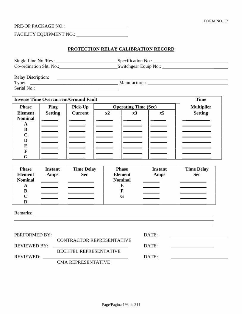
Page/Página 198 de 311
FORM NO. 17PRE-OP PACKAGE NO.:
FACILITY EQUIPMENT NO.:
PROTECTION RELAY CALIBRATION RECORD
Single Line No./Rev: Specification No.: Co-ordination Sht. No.: Switchgear Equip No.: ______
Relay Discription: Type: _____________________________________ Manufacturer: Serial No.: ________
Inverse Time Overcurrent/Ground Fault Time
Phase Plug Pick-Up Operating Time (Sec) MultiplierElement Setting Current x2 x3 x5 SettingNominal ______ ______ ______ ______ _____ __________
A _______ _______ _______ ________ _______ ____________B _______ _______ _______ ________ _______ ____________C _______ _______ _______ ________ _______ ____________D _______ _______ _______ ________ _______ ____________E _______ _______ _______ ________ _______ ____________F _______ _______ _______ ________ _______ ____________G _______ _______ _______ ________ _______ ____________
Phase Instant Time Delay Phase Instant Time DelayElement Amps Sec Element Amps SecNominal _______ ___________ Nominal _______ ___________
A _______ ___________ E _______ ___________B _______ ___________ F _______ ___________C _______ ___________ G _______ ___________D _______ ___________ _______ ___________
Remarks:
PERFORMED BY: DATE: CONTRACTOR REPRESENTATIVE
REVIEWED BY: DATE: BECHTEL REPRESENTATIVE
REVIEWED: DATE: CMA REPRESENTATIVE

Page/Página 199 de 311
FORM NO. 18-1PRE-OP PACKAGE NO:
FACILITY EQUIPMENT NO.:
MEDIUM-VOLTAGE MOTOR CONTACTOR TEST RECORD
MCC No.: Cubicle No.: Contactor No.:
Motor No.: Motor kW : Contactor Rating:
Isolator Rating: O/L Rating : Control Voltage:
Motor FLC: O/L Tested : For % Load
Thermistor Type Operating Resistance
Single Line No./Rev.:
Control Scheme No./Rev: Starter Scheme No./Rev.
Switch Fuse Unit:
Visual Inspection
Electrical Connections
Mechanism Operation
Mechanical Interlock Operation
Electrical Interlock Operation
Fuse Rating
Contactor Carriage:
Carriage - Rail Alignment
Carriage Operation
Withdrawal Mechanism Operation
Locking Mechanism Operation
Isolating Mechanism Operation
Grounding Mechanism Operation
Mechanism Interlock Operation
Electrical Interlock Operation

Page/Página 200 de 311
FORM NO. 18-2RE-OP PACKAGE NO.:
FACILITY EQUIPMENT NO.:
MEDIUM-VOLTAGE MOTOR CONTACTOR TEST RECORD
Contactor:
Visual Inspection
Closing Spring Operation
Arcing Contacts Alignment
Arcing Contacts Pressure
Main Contacts Alignment
Main Contacts Pressure
Safety Shutter Operation
Isolating Mechanism Operation
Closing Coil Operation
Trip Coil Operation
Arch Chutes and Insulation Barriers
Insulating Oil:
Oil Type Correct Level
Electric Strength Test at Volts for minutes
Sample No. 1 Sample No. 2
Sample No. 3
Insulation Resistance:
Megger Volts for minutes
A-B -C C-A
A-G B-G C-G
Grounding:
Busbar Grounding Operation
Circuit Grounding Operation

Page/Página 201 de 311
FORM NO. 18-3
PRE-OP PACKAGE NO.:
FACILITY EQUIPMENT NO.:
MEDIUM-VOLTAGE MOTOR CONTACTOR TEST RECORD
Auxiliary Relays:
Visual Inspection
Electrical Connections
Contacts Mechanical Operation
Relays Mechanism Operation
Control Wiring Continuity
Relays Operation in Test Position
Relays Operation in Service Position
Control Fuse Rating
Protection and Metering System:
Visual Inspection
Electrical Connections
Protection C.T. Ratio A B C
Metering C.T. Ratio A B C
Core Balance C.T. Ratio
Ground Leakage C.T. Ratio
C.T. Polarity Check - Flick Test:
PHASE PROTECTION METERING
A B C
Core Balance Ground Leakage
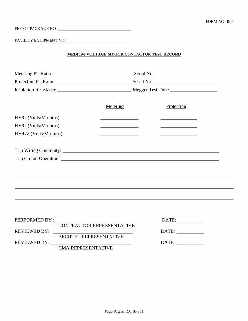
Page/Página 202 de 311
FORM NO. 18-4
PRE-OP PACKAGE NO.:
FACILITY EQUIPMENT NO.:
MEDIUM-VOLTAGE MOTOR CONTACTOR TEST RECORD
Metering PT Ratio Serial No.
Protection PT Ratio Serial No.
Insulation Resistance Megger Test Time
Metering Protection
HV/G (Volts/M-ohms)
HV/G (Volts/M-ohms)
HV/LV (Volts/M-ohms)
Trip Wiring Continuity:
Trip Circuit Operation:
PERFORMED BY : DATE: CONTRACTOR REPRESENTATIVE
REVIEWED BY: DATE: BECHTEL REPRESENTATIVE
REVIEWED BY: DATE: CMA REPRESENTATIVE

Page/Página 203 de 311
FORM NO. 19-1PRE-OP PACKAGE NO.: __________________________________
FACILITY EQUIPMENT NO.:
480 VOLTAGE MOTOR CONTACTOR TEST RECORD
MCC No.: Cubicle No.: Contactor No.
Motor No.: Motor kW : Contactor Rating
Isolator Rating: O/L Rating : Control Voltage
MTR FLC O/L Tested @ for % Load
Thermistor type Operating Resistance
Single Line No./Rev.:
Control Scheme No./Rev.: Starter Scheme No./Rev.
Motor Circuit Protector:
Visual Inspection: Electrical Conn's
Mechanical Operation: Mech Intlk Operation
Contractor and Relays:
Visual Inspection; Electrical Conn's
Contactor Coil Rating: Aux Relay Rating
Fuse Rating: Contr. Fuse Rating
Mech Operation: Contactor Aux Contacts Aux Relay
Wiring Continuity: Power Control
Megger Volts: Time
Breaker Closed (M-ohms) A/G B/G C/G
Breaker Open (M-ohms) A/B B/C C/A
Operation: Hand Close Hand Trip Trip Reset
Hand Charge Close Trip

Page/Página 204 de 311
FORM NO. 10-2
PRE-OP PACKAGE NO.:
FACILITY EQUIPMENT NO.:
480V MOTOR CONTACTOR TEST RECORD
Protection and Metering System:
Visual Inspection
Electrical Connections
Protection C.T. Ratio A B C
Metering C.T. Ratio A B C
C.T. Polarity Check - Flick Test:
Phase Protection Metering
A B C
C.T. Polarity Check - Primary Injection Test:
Phase Protection Metering
A B C
Trip Wiring
Trip Circuit Operation
Remarks
PERFORMED BY : DATE: CONTRACTOR REPRESENTATIVE
REVIEWED BY: DATE: BECHTEL REPRESENTATIVE
REVIEWED BY: DATE: CMA REPRESENTATIVE

Page/Página 205 de 311
FORM NO. 20PRE-OP PACKAGE NO.: FACILITY EQUIPMENT NO.:
SQUIRREL CAGE MOTOR TEST RECORD
Mfg. HP Volts Amps Frame Ins. Class Rise °C Service Factor RPM Rotation (View @ O/B End) Brg. Type Starter Size MCC No. Cubicle No. Single Line No./Rev. Control Scheme No./Rev Data Sht No/Rev Hand Rotation Cond. Drain. Megger Volts Test Time
INSUL RESISTANCE A/G B/G C/G
Before RunMegohms
WINDING DRYOUT
REQUIRED
After RunMegohms
UNCOUPLED TEST RUN
TIME
Lubrication Ventilation Bearing Temp (1/B) (O/B) Bearing Vibr (1/B) (O/B) Bearing Temp Sensors Bearing Temp Sensors Winding Temp Sensors Anti-Cond Htr Frame Earth
CURRENT PER PHASE A B C
No Load Amps Starting Amps
Full Load Amps Cable Size
Remarks
PERFORMED BY : DATE: CONTRACTOR REPRESENTATIVE
REVIEWED BY: DATE: BECHTEL REPRESENTATIVE
REVIEWED BY: DATE: CMA REPRESENTATIVE
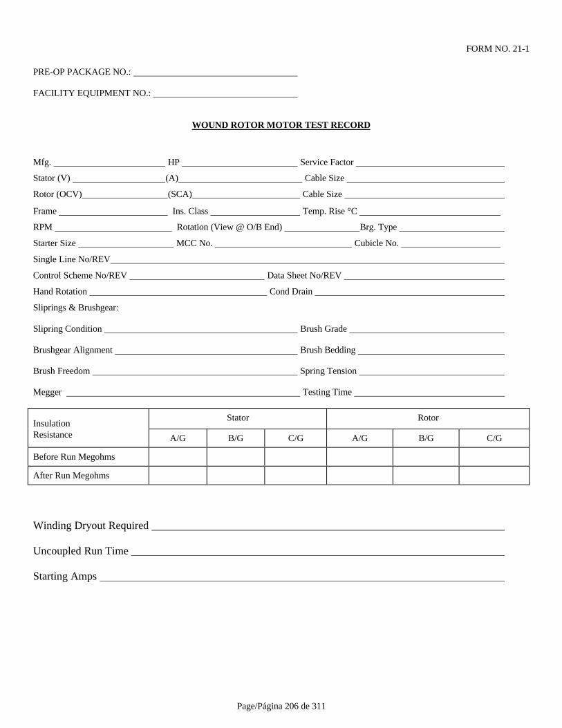
Page/Página 206 de 311
FORM NO. 21-1
PRE-OP PACKAGE NO.:
FACILITY EQUIPMENT NO.:
WOUND ROTOR MOTOR TEST RECORD
Mfg. HP Service Factor
Stator (V) (A) Cable Size
Rotor (OCV) (SCA) Cable Size
Frame Ins. Class Temp. Rise °C
RPM Rotation (View @ O/B End) Brg. Type
Starter Size MCC No. Cubicle No.
Single Line No/REV
Control Scheme No/REV Data Sheet No/REV
Hand Rotation Cond Drain
Sliprings & Brushgear:
Slipring Condition Brush Grade
Brushgear Alignment Brush Bedding
Brush Freedom Spring Tension
Megger Testing Time
InsulationStator Rotor
Resistance A/G B/G C/G A/G B/G C/G
Before Run Megohms
After Run Megohms
Winding Dryout Required
Uncoupled Run Time
Starting Amps

Page/Página 207 de 311
FORM NO. 21-2
PRE-OP PACKAGE NO.:
FACILITY EQUIPMENT NO.:
WOUND ROTOR MOTOR TEST RECORD
Lubrication Ventilation
Bearing Temp (I/B) (O/B)
Bearing Vibr (I/B) (O/B)
Bearing Temp. Sensors
Winding Temp. Sensors
Anti-Cond Heater
Frame Grounding
Stator No Load Amps (A) (B) (C)
Remarks
PERFORMED BY : DATE: CONTRACTOR REPRESENTATIVE
REVIEWED BY: DATE: BECHTEL REPRESENTATIVE
REVIEWED BY: DATE: CMA REPRESENTATIVE
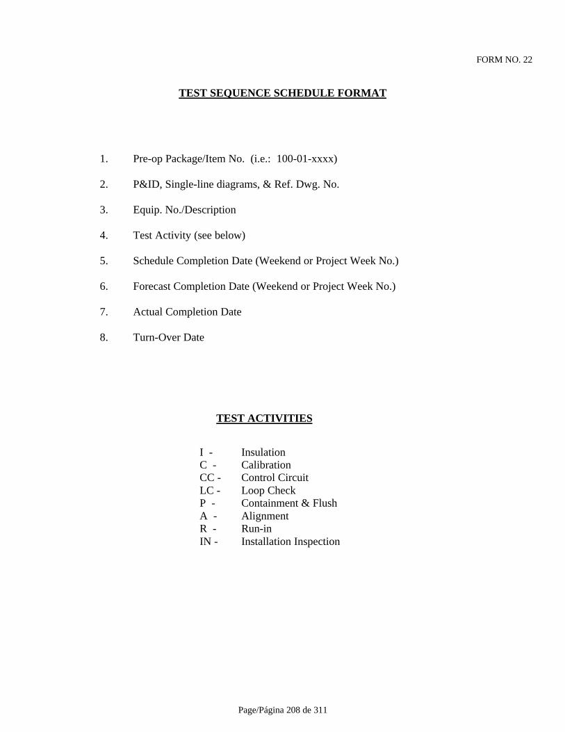
Page/Página 208 de 311
FORM NO. 22
TEST SEQUENCE SCHEDULE FORMAT
1. Pre-op Package/Item No. (i.e.: 100-01-xxxx)
2. P&ID, Single-line diagrams, & Ref. Dwg. No.
3. Equip. No./Description
4. Test Activity (see below)
5. Schedule Completion Date (Weekend or Project Week No.)
6. Forecast Completion Date (Weekend or Project Week No.)
7. Actual Completion Date
8. Turn-Over Date
TEST ACTIVITIES
I - InsulationC - CalibrationCC - Control CircuitLC - Loop CheckP - Containment & FlushA - AlignmentR - Run-inIN - Installation Inspection
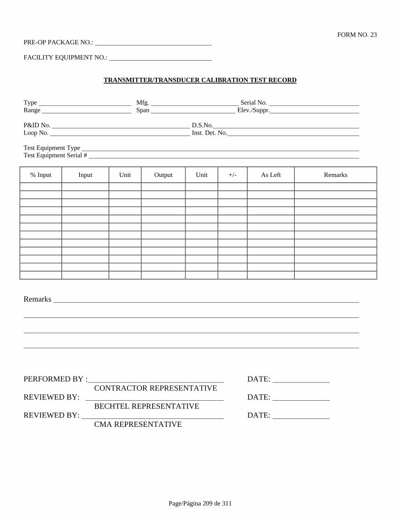
Page/Página 209 de 311
FORM NO. 23PRE-OP PACKAGE NO.:
FACILITY EQUIPMENT NO.:
TRANSMITTER/TRANSDUCER CALIBRATION TEST RECORD
Type Mfg. Serial No. Range Span Elev./Suppr.
P&ID No. D.S.No. Loop No. Inst. Det. No.
Test Equipment Type Test Equipment Serial #
% Input Input Unit Output Unit +/- As Left Remarks
Remarks
PERFORMED BY : DATE: CONTRACTOR REPRESENTATIVE
REVIEWED BY: DATE: BECHTEL REPRESENTATIVE
REVIEWED BY: DATE: CMA REPRESENTATIVE
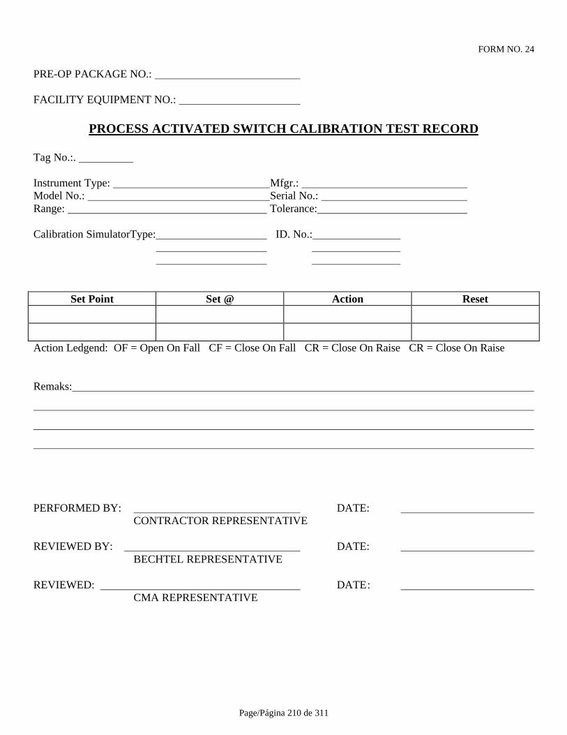
Page/Página 210 de 311
FORM NO. 24
PRE-OP PACKAGE NO.:
FACILITY EQUIPMENT NO.:
PROCESS ACTIVATED SWITCH CALIBRATION TEST RECORD
Tag No.:.
Instrument Type: Mfgr.: Model No.: Serial No.: Range: Tolerance:
Calibration SimulatorType: ID. No.:
Set Point Set @ Action Reset
Action Ledgend: OF = Open On Fall CF = Close On Fall CR = Close On Raise CR = Close On Raise
Remaks:
PERFORMED BY: DATE: CONTRACTOR REPRESENTATIVE
REVIEWED BY: DATE: BECHTEL REPRESENTATIVE
REVIEWED: DATE: CMA REPRESENTATIVE

Page/Página 211 de 311
FORM NO. 25PRE-OP PACKAGE NO.:
FACILITY EQUIPMENT NO.:
CONTROL VALVE CALIBRATION TEST RECORD
Tag No.:.
ValveMfgr.: Model No.: Serial No.: Positioner Mfg.: Model No.: Serial No.: Control Signal: Fail Position: Regulator Pressure Set:
Calibration SimulatorType: ID. No.:
POSITIONER VALVE% Input Input Value Units Output Units Position Feedback
0
25
50
75
100
Remaks:
PERFORMED BY: DATE: CONTRACTOR REPRESENTATIVE
REVIEWED BY: DATE: BECHTEL REPRESENTATIVE
REVIEWED: DATE: CMA REPRESENTATIVE
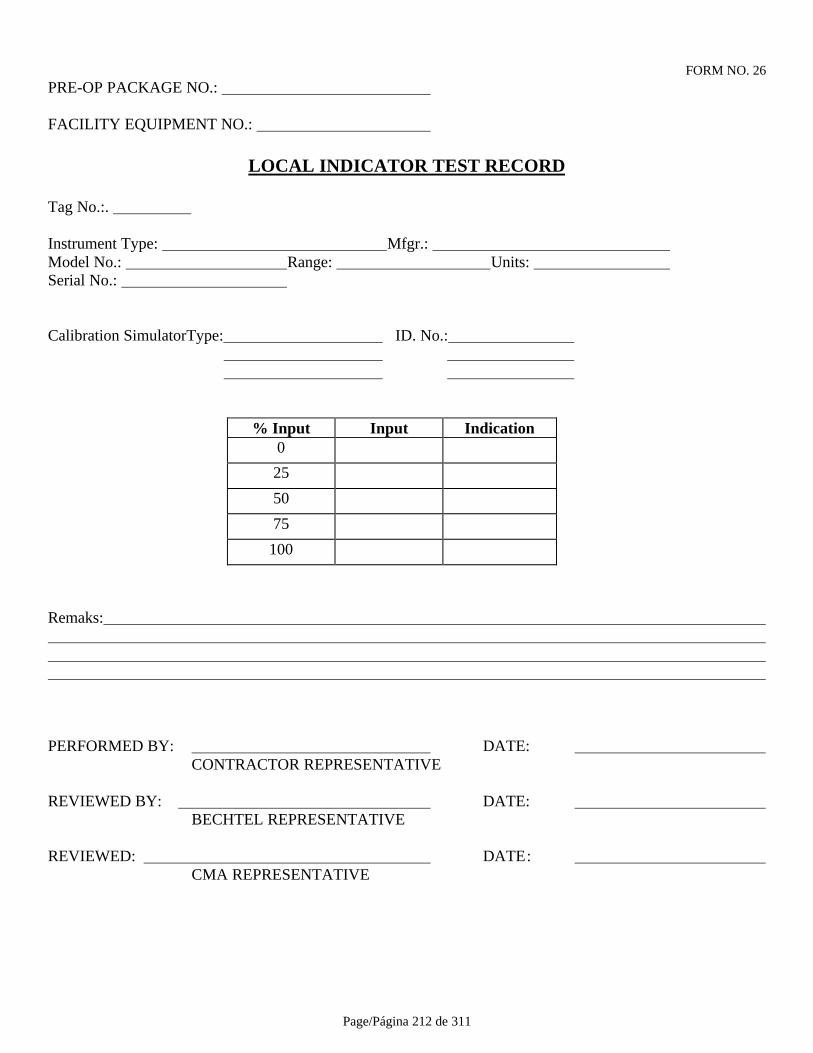
Page/Página 212 de 311
FORM NO. 26PRE-OP PACKAGE NO.:
FACILITY EQUIPMENT NO.:
LOCAL INDICATOR TEST RECORD
Tag No.:.
Instrument Type: Mfgr.: Model No.: Range: Units: Serial No.:
Calibration SimulatorType: ID. No.:
% Input Input Indication0
25
50
75
100
Remaks:
PERFORMED BY: DATE: CONTRACTOR REPRESENTATIVE
REVIEWED BY: DATE: BECHTEL REPRESENTATIVE
REVIEWED: DATE: CMA REPRESENTATIVE
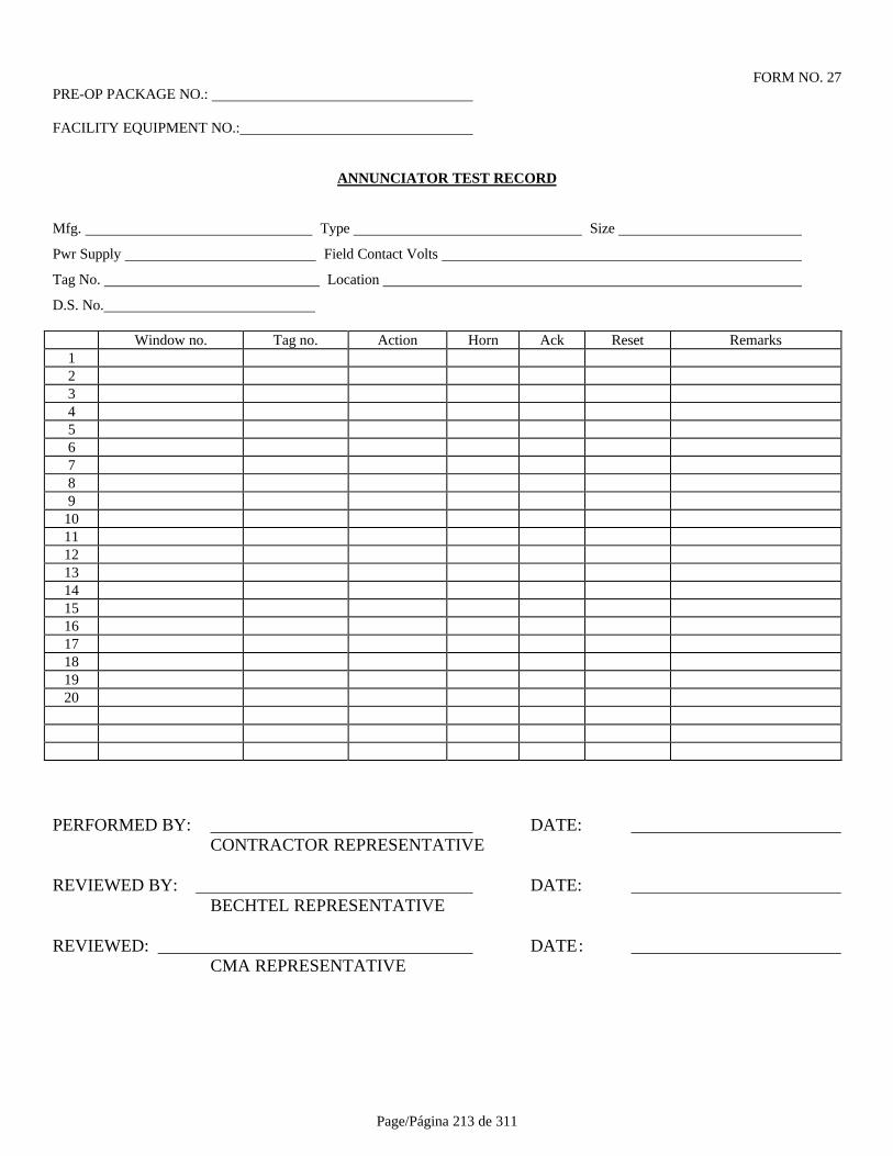
Page/Página 213 de 311
FORM NO. 27PRE-OP PACKAGE NO.:
FACILITY EQUIPMENT NO.:
ANNUNCIATOR TEST RECORD
Mfg. Type Size
Pwr Supply Field Contact Volts
Tag No. Location
D.S. No.
Window no. Tag no. Action Horn Ack Reset Remarks123456789
1011121314151617181920
PERFORMED BY: DATE: CONTRACTOR REPRESENTATIVE
REVIEWED BY: DATE: BECHTEL REPRESENTATIVE
REVIEWED: DATE: CMA REPRESENTATIVE

Page/Página 214 de 311
FORM NO. 28PRE-OP PACKAGE NO.:
FACILITY EQUIPMENT NO.:
HVAC BALANCING TEST RECORD
Mfg. Model No. Serial No.
BTU m3/h kW
Area Opening K Required Preliminary Final
Served No. Size Factor Vel m3/h Vel m3/h Vel m3/h Vel m3/h
Remarks
PERFORMED BY: DATE: CONTRACTOR REPRESENTATIVE
REVIEWED BY: DATE: BECHTEL REPRESENTATIVE
REVIEWED: DATE: CMA REPRESENTATIVE

Page/Página 215 de 311
FORM NO. 29PRE-OP PACKAGE NO.:
FACILITY EQUIPMENT NO.:
MOTOR OPERATED CONTROL VALVE TEST RECORD
Valve Type/Size Mfg. Serial No.
Actuator Type/Size Action Signal Range
Transducer Type Action Fail Mode
Limit SW Open Limit SW Closed
Torque SW open Torque SW Closed
Cycle Time: Open Closed
NLC : Open Closed
FLC : Open Closed
Calibrating Simulator Type
Read Out Type
Remarks
PERFORMED BY: DATE: CONTRACTOR REPRESENTATIVE
REVIEWED BY: DATE: BECHTEL REPRESENTATIVE
REVIEWED: DATE: CMA REPRESENTATIVE
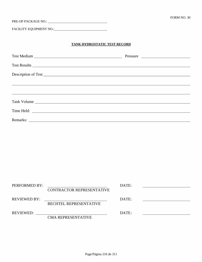
Page/Página 216 de 311
FORM NO. 30PRE-OP PACKAGE NO.:
FACILITY EQUIPMENT NO.:
TANK HYDROSTATIC TEST RECORD
Test Medium Pressure
Test Results
Description of Test
Tank Volume
Time Held:
Remarks:
PERFORMED BY: DATE: CONTRACTOR REPRESENTATIVE
REVIEWED BY: DATE: BECHTEL REPRESENTATIVE
REVIEWED: DATE: CMA REPRESENTATIVE

Page/Página 217 de 311
FORM NO. 31
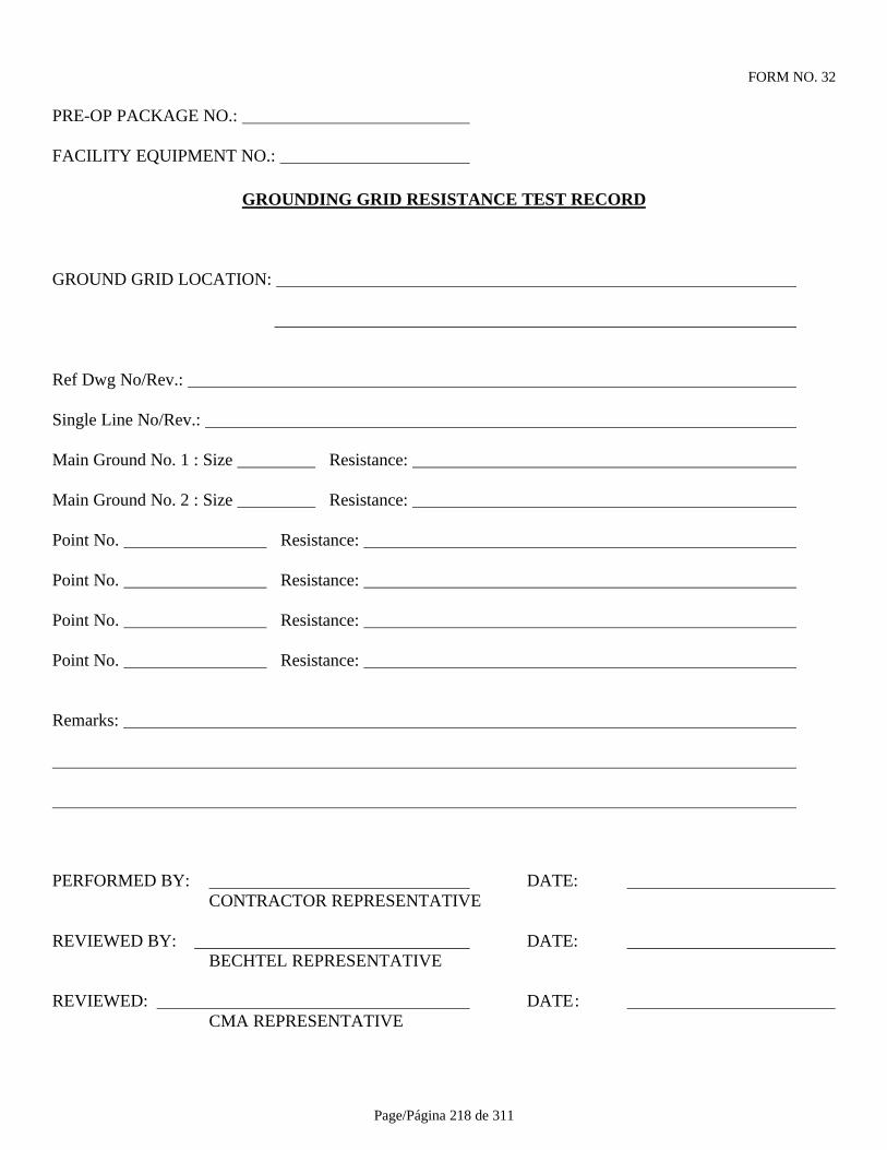
Page/Página 218 de 311
FORM NO. 32
PRE-OP PACKAGE NO.:
FACILITY EQUIPMENT NO.:
GROUNDING GRID RESISTANCE TEST RECORD
GROUND GRID LOCATION:
Ref Dwg No/Rev.:
Single Line No/Rev.:
Main Ground No. 1 : Size Resistance:
Main Ground No. 2 : Size Resistance:
Point No. Resistance:
Point No. Resistance:
Point No. Resistance:
Point No. Resistance:
Remarks:
PERFORMED BY: DATE: CONTRACTOR REPRESENTATIVE
REVIEWED BY: DATE: BECHTEL REPRESENTATIVE
REVIEWED: DATE: CMA REPRESENTATIVE
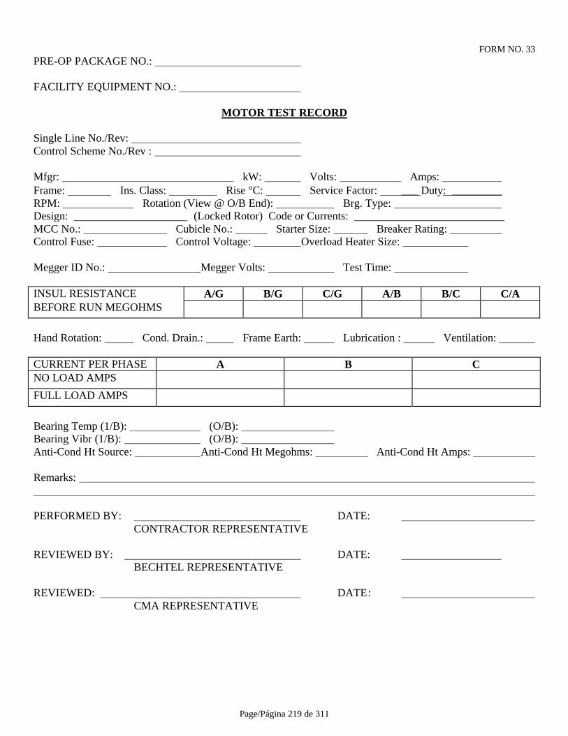
Page/Página 219 de 311
FORM NO. 33PRE-OP PACKAGE NO.:
FACILITY EQUIPMENT NO.:
MOTOR TEST RECORD
Single Line No./Rev: Control Scheme No./Rev :
Mfgr: kW: Volts: Amps: Frame: Ins. Class: Rise °C: Service Factor: ___ Duty: _________RPM: Rotation (View @ O/B End): Brg. Type: Design: ____________________ (Locked Rotor) Code or Currents: ___________________________MCC No.: Cubicle No.: Starter Size: Breaker Rating: Control Fuse: Control Voltage: Overload Heater Size:
Megger ID No.: Megger Volts: Test Time:
INSUL RESISTANCE A/G B/G C/G A/B B/C C/ABEFORE RUN MEGOHMS
Hand Rotation: Cond. Drain.: Frame Earth: Lubrication : Ventilation:
CURRENT PER PHASE A B CNO LOAD AMPS
FULL LOAD AMPS
Bearing Temp (1/B): (O/B): Bearing Vibr (1/B): (O/B): Anti-Cond Ht Source: Anti-Cond Ht Megohms: Anti-Cond Ht Amps:
Remarks:
PERFORMED BY: DATE: CONTRACTOR REPRESENTATIVE
REVIEWED BY: DATE: BECHTEL REPRESENTATIVE
REVIEWED: DATE: CMA REPRESENTATIVE

Page/Página 220 de 311
FORM NO. 34
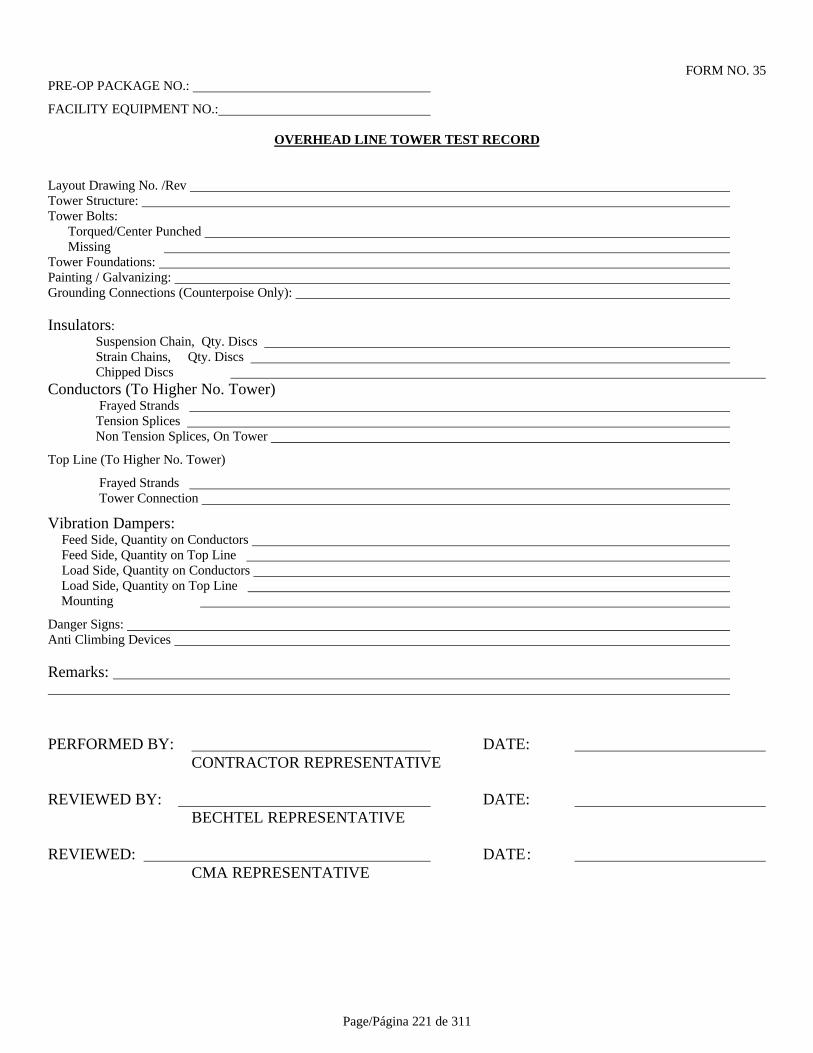
Page/Página 221 de 311
FORM NO. 35PRE-OP PACKAGE NO.:
FACILITY EQUIPMENT NO.:
OVERHEAD LINE TOWER TEST RECORD
Layout Drawing No. /Rev Tower Structure: Tower Bolts: Torqued/Center Punched Missing Tower Foundations: Painting / Galvanizing: Grounding Connections (Counterpoise Only):
Insulators:Suspension Chain, Qty. Discs Strain Chains, Qty. Discs Chipped Discs
Conductors (To Higher No. Tower) Frayed Strands Tension Splices Non Tension Splices, On Tower
Top Line (To Higher No. Tower)
Frayed Strands Tower Connection
Vibration Dampers: Feed Side, Quantity on Conductors Feed Side, Quantity on Top Line Load Side, Quantity on Conductors Load Side, Quantity on Top Line Mounting
Danger Signs: Anti Climbing Devices
Remarks:
PERFORMED BY: DATE: CONTRACTOR REPRESENTATIVE
REVIEWED BY: DATE: BECHTEL REPRESENTATIVE
REVIEWED: DATE: CMA REPRESENTATIVE
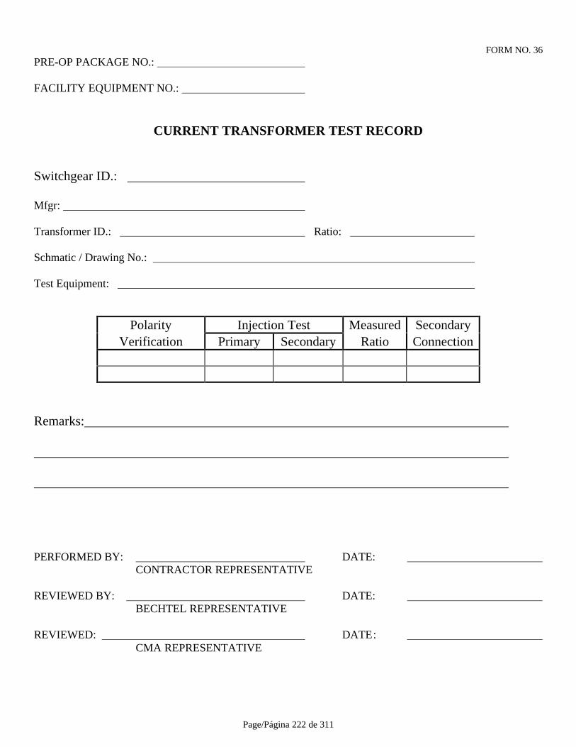
Page/Página 222 de 311
FORM NO. 36PRE-OP PACKAGE NO.:
FACILITY EQUIPMENT NO.:
CURRENT TRANSFORMER TEST RECORD
Switchgear ID.:
Mfgr:
Transformer ID.: Ratio:
Schmatic / Drawing No.:
Test Equipment:
Polarity Injection Test Measured SecondaryVerification Primary Secondary Ratio Connection
Remarks:
PERFORMED BY: DATE: CONTRACTOR REPRESENTATIVE
REVIEWED BY: DATE: BECHTEL REPRESENTATIVE
REVIEWED: DATE: CMA REPRESENTATIVE
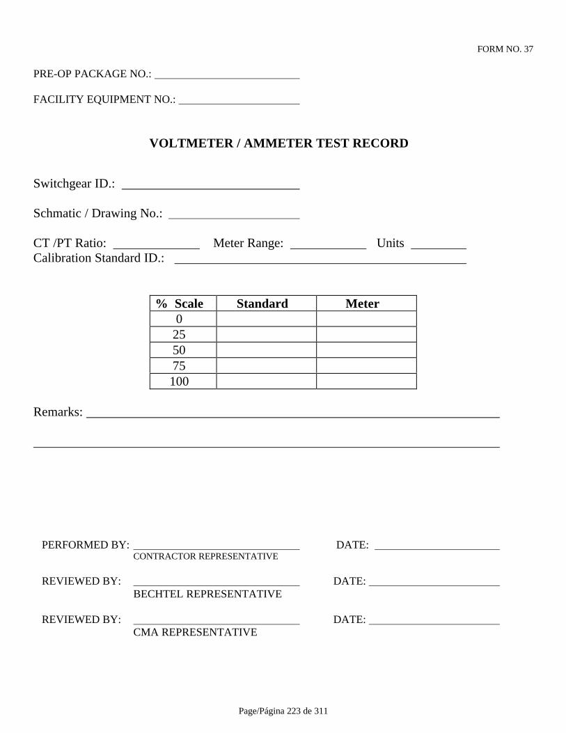
Page/Página 223 de 311
FORM NO. 37
PRE-OP PACKAGE NO.:
FACILITY EQUIPMENT NO.:
VOLTMETER / AMMETER TEST RECORD
Switchgear ID.:
Schmatic / Drawing No.:
CT /PT Ratio: Meter Range: Units Calibration Standard ID.:
% Scale Standard Meter0
255075100
Remarks:
PERFORMED BY: DATE: CONTRACTOR REPRESENTATIVE
REVIEWED BY: DATE: BECHTEL REPRESENTATIVE
REVIEWED BY: DATE: CMA REPRESENTATIVE
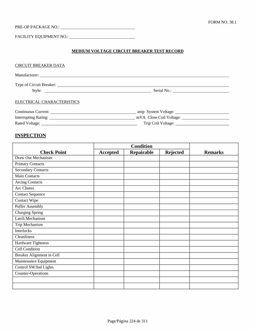
Page/Página 224 de 311
FORM NO. 38.1PRE-OP PACKAGE NO.:
FACILITY EQUIPMENT NO.:
MEDIUM VOLTAGE CIRCUIT BREAKER TEST RECORD
CIRCUIT BREAKER DATA
Manufacturer:
Type of Circuit Breaker: Style: Serial No.:
ELECTRICAL CHARACTERISTICS
Continuous Current: amp System Voltage: Interrupting Rating: mVA Close Coil Voltage: Rated Voltage: Trip Coil Voltage:
INSPECTION
ConditionCheck Point Accepted Repairable Rejected Remarks
Draw Out Mechanism
Primary Contacts
Secondary Contacts
Main Contacts
Arcing Contacts
Arc Chutes
Contact Sequence
Contact Wipe
Puffer Assembly
Charging Spring
Latch Mechanism
Trip Mechanism
Interlocks
Cleanliness
Hardware Tightness
Cell Condition
Breaker Alignment in Cell
Maintenance Equipment
Control SW/Ind Lights
Counter-Operations
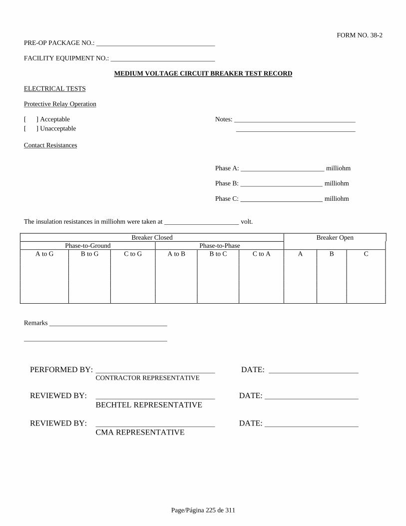
Page/Página 225 de 311
FORM NO. 38-2PRE-OP PACKAGE NO.:
FACILITY EQUIPMENT NO.:
MEDIUM VOLTAGE CIRCUIT BREAKER TEST RECORD
ELECTRICAL TESTS
Protective Relay Operation
[ ] Acceptable Notes: [ ] Unacceptable
Contact Resistances
Phase A: milliohm
Phase B: milliohm
Phase C: milliohm
The insulation resistances in milliohm were taken at volt.
Breaker Closed Breaker OpenPhase-to-Ground Phase-to-Phase
A to G B to G C to G A to B B to C C to A A B C
Remarks
PERFORMED BY: DATE: CONTRACTOR REPRESENTATIVE
REVIEWED BY: DATE: BECHTEL REPRESENTATIVE
REVIEWED BY: DATE: CMA REPRESENTATIVE
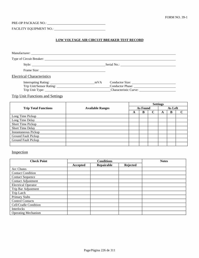
Page/Página 226 de 311
FORM NO. 39-1
PRE-OP PACKAGE NO.:
FACILITY EQUIPMENT NO.:
LOW VOLTAGE AIR CIRCUIT BREAKER TEST RECORD
Manufacturer:
Type of Circuit Breaker:
Style: Serial No.:
Frame Size:
Electrical Characteristics
Interrupting Rating: mVA Conductor Size: Trip Unit/Sensor Rating: Conductor Phase: Trip Unit Type: Characteristic Curve:
Trip Unit Functions and Settings
SettingsTrip Total Functions Available Ranges As Found As Left
A B C A B CLong Time PickupLong Time DelayShort Time PickupShort Time DelayInstantaneous PickupGround Fault PickupGround Fault Pickup
Inspection
Check Point Conditions NotesAccepted Repairable Rejected
Arc ChutesContact ConditionContact SequenceContact AdjustmentElectrical OperatorTrip Bar AdjustmentTrip LatchPrimary StabsControl ContactsCell/Cradle ConditionInterlocksOperating Mechanism
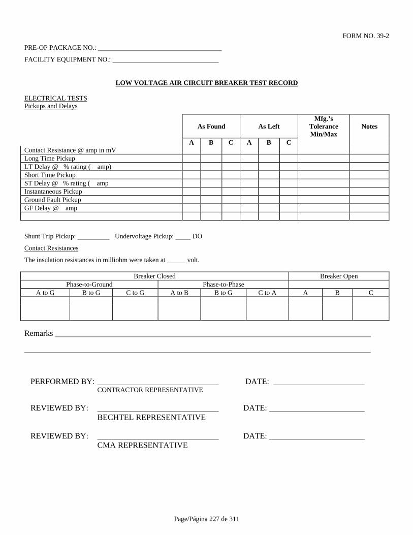
Page/Página 227 de 311
FORM NO. 39-2
PRE-OP PACKAGE NO.:
FACILITY EQUIPMENT NO.:
LOW VOLTAGE AIR CIRCUIT BREAKER TEST RECORD
ELECTRICAL TESTSPickups and Delays
As Found As LeftMfg.’s
ToleranceMin/Max
Notes
A B C A B CContact Resistance @ amp in mVLong Time PickupLT Delay @ % rating ( amp)Short Time PickupST Delay @ % rating ( ampInstantaneous PickupGround Fault PickupGF Delay @ amp
Shunt Trip Pickup: Undervoltage Pickup: DO
Contact Resistances
The insulation resistances in milliohm were taken at volt.
Breaker Closed Breaker OpenPhase-to-Ground Phase-to-Phase
A to G B to G C to G A to B B to G C to A A B C
Remarks
PERFORMED BY: DATE: CONTRACTOR REPRESENTATIVE
REVIEWED BY: DATE: BECHTEL REPRESENTATIVE
REVIEWED BY: DATE: CMA REPRESENTATIVE
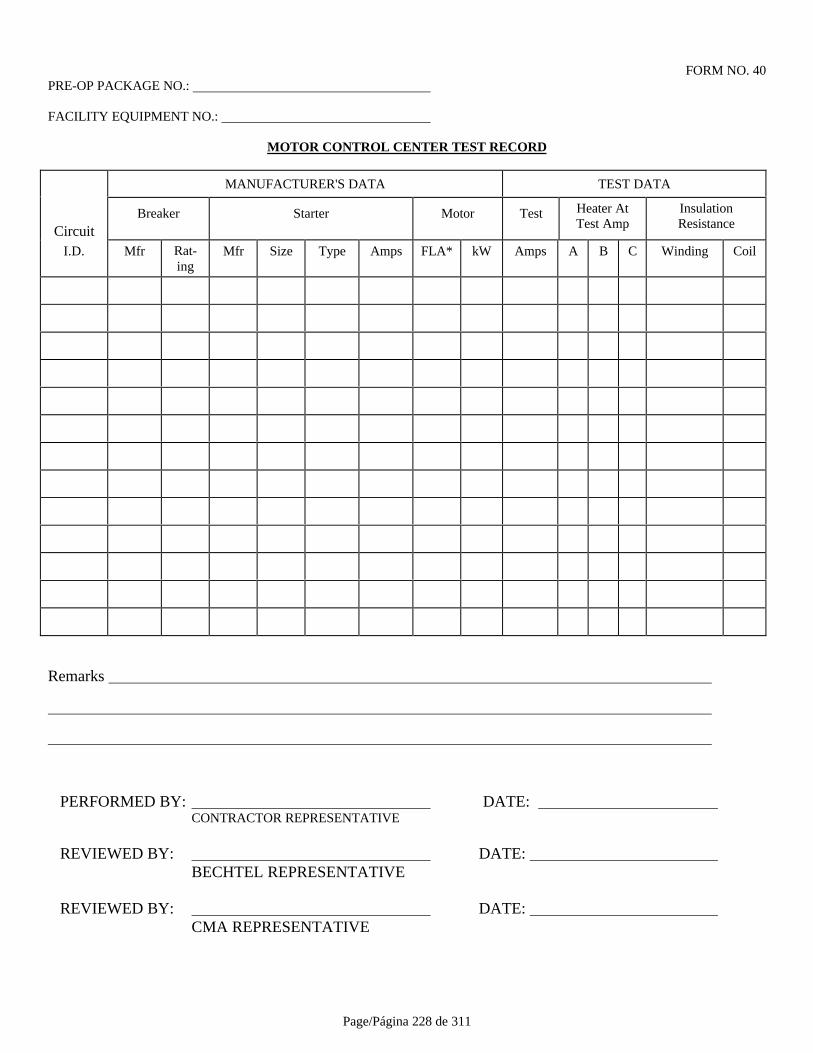
Page/Página 228 de 311
FORM NO. 40PRE-OP PACKAGE NO.:
FACILITY EQUIPMENT NO.:
MOTOR CONTROL CENTER TEST RECORD
MANUFACTURER'S DATA TEST DATA
CircuitBreaker Starter Motor Test Heater At
Test AmpInsulationResistance
I.D. Mfr Rat-ing
Mfr Size Type Amps FLA* kW Amps A B C Winding Coil
Remarks
PERFORMED BY: DATE: CONTRACTOR REPRESENTATIVE
REVIEWED BY: DATE: BECHTEL REPRESENTATIVE
REVIEWED BY: DATE: CMA REPRESENTATIVE
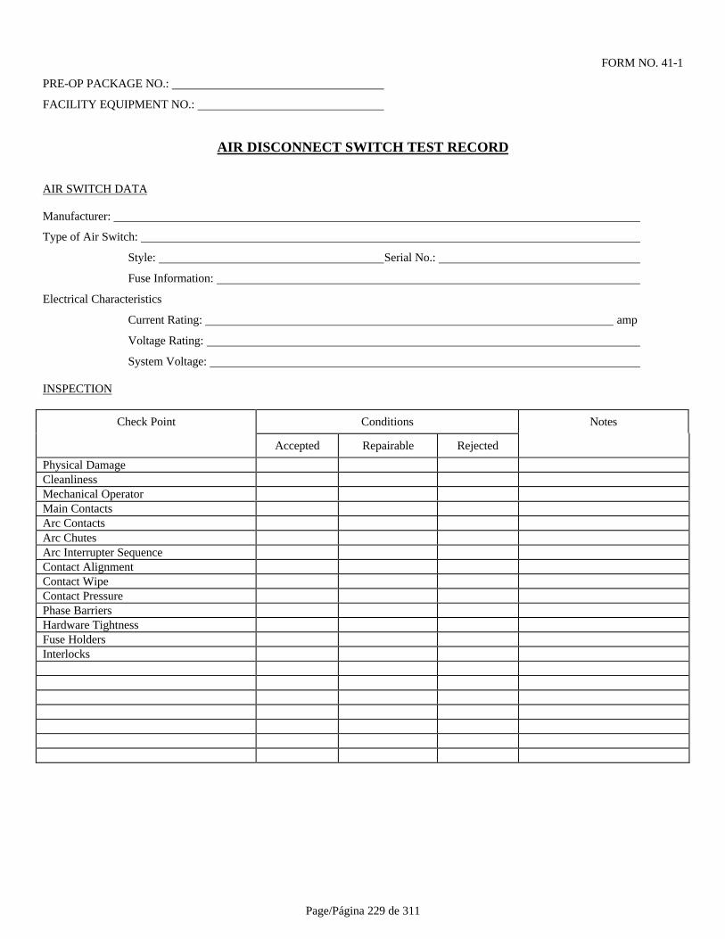
Page/Página 229 de 311
FORM NO. 41-1
PRE-OP PACKAGE NO.:
FACILITY EQUIPMENT NO.:
AIR DISCONNECT SWITCH TEST RECORD
AIR SWITCH DATA
Manufacturer:
Type of Air Switch:
Style: Serial No.:
Fuse Information:
Electrical Characteristics
Current Rating: amp
Voltage Rating:
System Voltage:
INSPECTION
Check Point Conditions Notes
Accepted Repairable Rejected
Physical DamageCleanlinessMechanical OperatorMain ContactsArc ContactsArc ChutesArc Interrupter SequenceContact AlignmentContact WipeContact PressurePhase BarriersHardware TightnessFuse HoldersInterlocks

Page/Página 230 de 311
FORM NO. 41-2PRE-OP PACKAGE NO.:
FACILITY EQUIPMENT NO.:
AIR DISCONNECT SWITCH TEST RECORD
ELECTRICAL TESTS
Contact Resistances
Phase A: milliohmPhase B: milliohmPhase C: milliohm
Contact Resistances
The insulation resistances in milliohm were taken at volt.
Switch Closed Switch OpenPhase-to-Ground Phase-to-Phase
A to G B to G C to G A to B B to G C to A A B C
Remarks
PERFORMED BY: DATE: CONTRACTOR REPRESENTATIVE
REVIEWED BY: DATE: BECHTEL REPRESENTATIVE
REVIEWED BY: DATE: CMA REPRESENTATIVE

Page/Página 231 de 311
FORM NO. 42-1
PRE-OP PACKAGE NO.:
FACILITY EQUIPMENT NO.:
SYNCHRONOUS MOTOR TEST RECORD
Mfg. HP Service Factor
Power Factor
Stator (V) (A) Cable Size
Type of Excitation: Brush Brushless
Frame Insulation Class Temp. Rise oC
RPM Bi-Directional Rotation
If not, Rotation facing Non-Drive End Brg. Type
Starting Method: Starter Circuit Breaker
Single Line No./Rev.
Starter Control Scheme No./Rev. Motor Data Sheet No./Rev.
Exciter Control Scheme No./Rev. V-Curve No./Rev.
PRE-OP TESTING
A) SLIPRINGS & BRUSHGEAR: (IF APPLICABLE)
Slipring Condition Brush Grade
Brushgear Alignment Brush Seating
Brush Freedom Spring Tension
B) INSULATION TESTING
Megger Rating Volts
Insulation Resistancein Megohms Stator Rotor RTD's
Bearing PedestalFront/Rear
FactoryTest
JobsiteTest
FactoryTest
JobsiteTest
FactoryTest
JobsiteTest
FactoryTest
JobsiteTest
Before RunAfter Run In
* CAUTION: Do not Megger solid state devices connected to rotor winding.
Winding Dryout Required Bearing pedestal grounding strapwas replaced after insulation check

Page/Página 232 de 311
FORM NO. 42-2
PRE-OP PACKAGE NO.:
FACILITY EQUIPMENT NO.:
C) BEARING AND ROTOR CHECKS
Oil Level Oil Ring Condition
Clutch Air Line Connection Air Line Valve Closed
Clutch Assembly Complete
Shipping blocks removed and shaft was rotated manually
D) EXCITER CHECKS
Control and power connections are per exciter schematic diagram
Field application relay or timer setting
No load excitation current Amps
VAR regulator setting % rated KVAR
NO LOAD RUN IN
Starting inrush current Amps
Line voltage drop on main bus %
Run-up time secondsNo load field current (Cold/Hot) / Amps
No load stator current (Cold/Hot) / Amps
Supply voltage (Before start/after synch.) / kV
Lubrication Ventilation
Bearing Temp (I/B) (O/B)
Bearing Vibr (I/B) (O/B)
Bearing Temp. Sensors
Winding Temp Sensors
Anti-Cond Heater
Frame Grounding

Page/Página 233 de 311
FORM NO. 42-3PRE-OP PACKAGE NO.:
FACILITY EQUIPMENT NO.:
SYNCHRONOUS MOTOR TEST RECORD
FULL LOAD OPERATION
Mill accelerating time sec. (Closing of clutch)
Field current Amps; Stator current Amps
Bearing Temp. (I/B) (O/B)
Bearing Vibr. (I/B) (O/B)
Wing Temp.
Remarks
PERFORMED BY: DATE: CONTRACTOR REPRESENTATIVE
REVIEWED BY: DATE: BECHTEL REPRESENTATIVE
REVIEWED BY: DATE: CMA REPRESENTATIVE

Page/Página 234 de 311
FORM NO. 43
OWNER ACCESS PERMIT
REQUESTED BY: DATE REQUIRED:
CONTRACTOR: ACCESS DATE:
FACILITY: ACCESS TIME:
EQUIPMENT NO.:
TASK DESCRIPTION:
WORK INCLUDES (CHECK APPLICABLE)
ARCHITECTURAL MECHANICAL INSTRUMENTATION CIVIL ELECTRICAL PRE-OP TESTING STRUCTURAL PIPING
ESTIMATED TIME REQUIRED: HOURS
OWNER OPERATOR REQUIRED: YES NO
ISOLATION/SHUTDOWN REQUIREMENTS:
PERFORMED BY: DATE: CONTRACTOR REPRESENTATIVE
REVIEWED BY: DATE: BECHTEL REPRESENTATIVE
REVIEWED BY: DATE: CMA REPRESENTATIVE

Page/Página 235 de 311
FORM NO. 44
TAG NOS: SERVICE:LINE OREQUIP. NO.: PIPE I.D.:
CHECKED AS COMPLETED CHECK AS COMPLETEDMEASURING ELEMENT: CONTROL VALVE:
INSTALLED CORRECTLY INSTALLATION AND LOCATION CORRECTLOCATION CORRECT TYPE AND SIZE CORRECTISOLATING VALVES CORRECT STROKE TESTED, LOCAL AND REMOTEMATERIALS CORRECT LIMIT SWITCH SETTING CORRECTORIFICE TAPS ORIENTATION CORRECT POSITIONER CHECKEDORIFICE DIAMETER: I/P TRANSDUCER CHECKED
IMPULSE CONNECTIONS: AIR SUPPLIES:CORRECT HOOK UP INSPECTED, BLOWN CLEAR & LEAK TESTEDMATERIALS CORRECT CONNECTED PER DETAIL DRAWINGPRESSURE TESTED TO LINE PRESSUREWEATHER PROTECTION CORRECT TRANSMISSION:
PNEUMATIC LINES INSPECTED, BLOWN CLEAR, &FIELD INSTRUMENT: LEAK TESTED
INSTALLATION PER DETAIL DRAWING CABLE TYPE & SIZE CORRECTWEATHER PROTECTION CORRECT GROUND & SHIELDS CORRECTPOWER SUPPLY CORRECTAIR SUPPLY CORRECT LOOP CHECK:MODEL NO. PER DATA SHEET LOOP WIRING CORRECT
TRANSMITTER TO LOOP DEVICES CORRECTPANEL INSTRUMENT: CONTROLLER OUTPUT TO LOOP DEVICES CORRECT
INSTRUMENT IDENTIFICATION CORRECT CONTROLLER ACTION CORRECTCHART/INDICATOR CORRECT ALARMS CORRECTALARM SWITCH CORRECT POINT AND GROUP DISPLAYS CORRECTALARM LEGEND CORRECT GRAPHIC AND SPECIAL DISPLAYS CORRECTPOWER/AIR SUPPLY CORRECT
TRANSMITTEROUTPUT
TRANSMITTEROUTPUT
TRANSMITTEROUTPUT
TRANSMITTEROUTPUT
TRANSMITTEROUTPUT
UP DOWN UP DOWN UP DOWN UP DOWN UP DOWNLOOP TEST @ 0% TX INPUTLOOP TEST @ 25% TX INPUTLOOP TEST @ 50% TX INPUTLOOP TEST @ 70% TX INPUTLOOP TEST @ 100% TX INPUT
REMARKS:
CHECKED BY..........................DATE....................WITNESSED BY.......................DATE....................ACCEPTED BY.........................DATE....................
ORIGIN INSTRUMENT LOOP TEST SHEET JOB NO.
LOOP NO. REV.
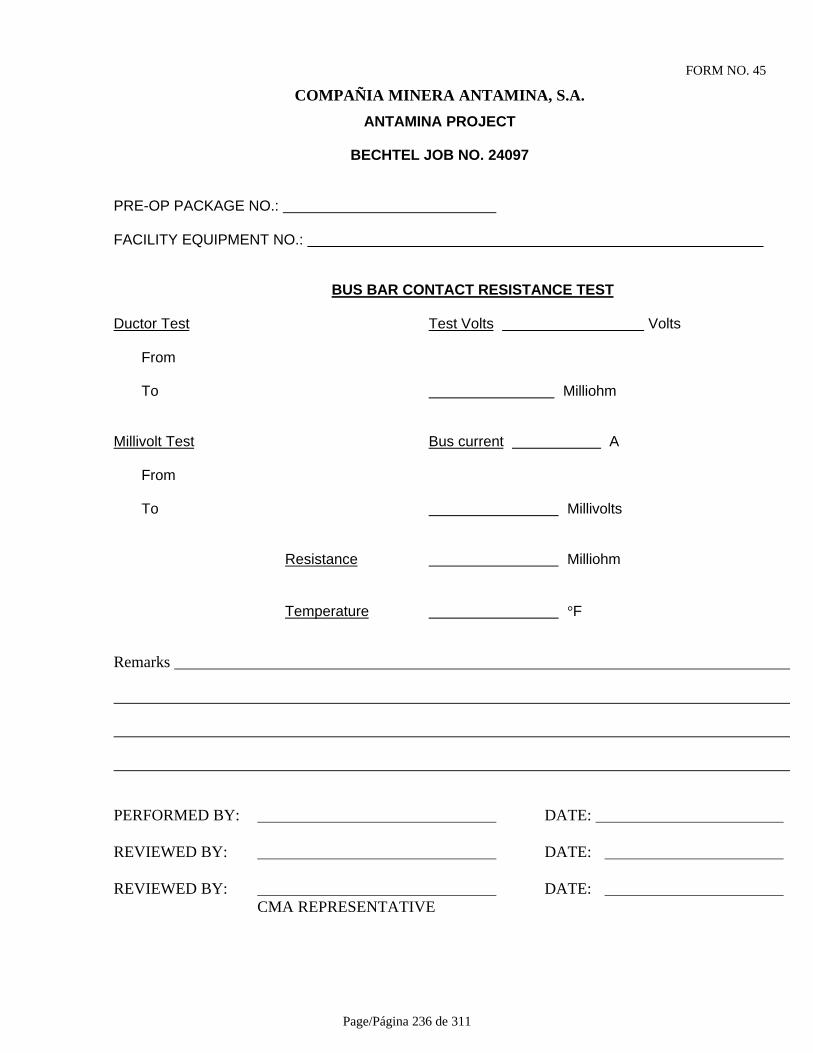
Page/Página 236 de 311
FORM NO. 45
COMPAÑIA MINERA ANTAMINA, S.A.
ANTAMINA PROJECT
BECHTEL JOB NO. 24097
PRE-OP PACKAGE NO.:
FACILITY EQUIPMENT NO.:
BUS BAR CONTACT RESISTANCE TEST
Ductor Test Test Volts Volts
From
To Milliohm
Millivolt Test Bus current A
From
To Millivolts
Resistance Milliohm
Temperature °F
Remarks
PERFORMED BY: DATE:
REVIEWED BY: DATE:
REVIEWED BY: DATE: CMA REPRESENTATIVE

Page/Página 237 de 311
FORM NO. 46PRE-OP PACKAGE NO.:
FACILITY EQUIPMENT NO.:
TRANSFORMER OIL DIELECTRIC TEST RECORD
Equipment No.: ______________________________________________________________________Description: _________________________________________________________________________
Mfgr.: Type: Rating: HV: LV Hz Serial No.: Cooling: Single Line/ Drawing Reference: ______
Test No. 1: Test No. 2:
Test No. 3: Test No. 4:
Test No. 5: Test No. 5:
Average: Minimum:
Remarks:
PERFORMED BY: DATE: CONTRACTOR REPRESENTATIVE
REVIEWED BY: DATE: BECHTEL REPRESENTATIVE
REVIEWED: DATE: CMA REPRESENTATIVE
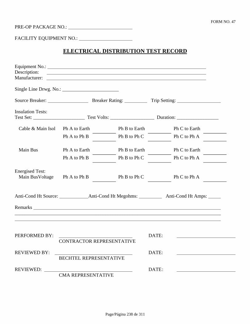
Page/Página 238 de 311
FORM NO. 47PRE-OP PACKAGE NO.:
FACILITY EQUIPMENT NO.:
ELECTRICAL DISTRIBUTION TEST RECORD
Equipment No.: Description: Manufacturer:
Single Line Drwg. No.: _______________________
Source Breaker: Breaker Rating: Trip Setting:
Insulation Tests:Test Set: _____________________ Test Volts: __________________ Duration: _________________
Cable & Main Isol Ph A to Earth Ph B to Earth Ph C to Earth
Ph A to Ph B Ph B to Ph C Ph C to Ph A
Main Bus Ph A to Earth Ph B to Earth Ph C to Earth
Ph A to Ph B Ph B to Ph C Ph C to Ph A
Energised Test:Main BusVoltage Ph A to Ph B Ph B to Ph C Ph C to Ph A
Anti-Cond Ht Source: Anti-Cond Ht Megohms: Anti-Cond Ht Amps:
Remarks ____________________________________________________________________________________
PERFORMED BY: DATE: CONTRACTOR REPRESENTATIVE
REVIEWED BY: DATE: BECHTEL REPRESENTATIVE
REVIEWED: DATE: CMA REPRESENTATIVE

Page/Página 239 de 311
FORM NO. 48PRE-OP PACKAGE NO.:
FACILITY EQUIPMENT NO.:
INSTRUMENT CALIBRATION
Tag No.:.
Instrument Type: Mfgr.: Model No.: Serial No.: Input Range: Output Range: Tolerance:
Calibration SimulatorType: ID. No.:
Specified Values As Read Value% Input Input Value Units Output Units Actual As Left
0
25
50
75
100
Remaks:
PERFORMED BY: DATE: CONTRACTOR REPRESENTATIVE
REVIEWED BY: DATE: BECHTEL REPRESENTATIVE
REVIEWED: DATE: CMA REPRESENTATIVE
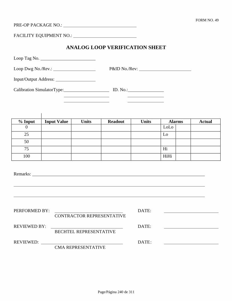
Page/Página 240 de 311
FORM NO. 49PRE-OP PACKAGE NO.:
FACILITY EQUIPMENT NO.:
ANALOG LOOP VERIFICATION SHEET
Loop Tag No.
Loop Dwg No./Rev.: P&ID No./Rev:
Input/Output Address:
Calibration SimulatorType: ID. No.:
% Input Input Value Units Readout Units Alarms Actual0 LoLo
25 Lo
50
75 Hi
100 HiHi
Remarks:
PERFORMED BY: DATE: CONTRACTOR REPRESENTATIVE
REVIEWED BY: DATE: BECHTEL REPRESENTATIVE
REVIEWED: DATE: CMA REPRESENTATIVE
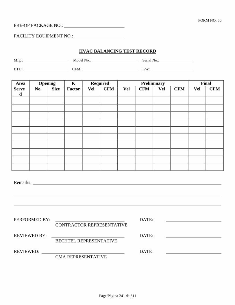
Page/Página 241 de 311
FORM NO. 50PRE-OP PACKAGE NO.:
FACILITY EQUIPMENT NO.:
HVAC BALANCING TEST RECORD
Mfgr: Model No.: Serial No.:
BTU: CFM: KW:
Area Opening K Required Preliminary FinalServe
dNo. Size Factor Vel CFM Vel CFM Vel CFM Vel CFM
Remarks:
PERFORMED BY: DATE: CONTRACTOR REPRESENTATIVE
REVIEWED BY: DATE: BECHTEL REPRESENTATIVE
REVIEWED: DATE: CMA REPRESENTATIVE

Page/Página 242 de 311
FORM NO. 51PRE-OP PACKAGE NO.:
FACILITY EQUIPMENT NO.:
ADDITIONAL CIRCUIT TEST RECORD
Type: Mfgr: Model No.:
Function:
P&ID No.: SLD No.:
Loop No.: Scheme No.:
Test :
Test Equipment:
Results:
Remarks :
PERFORMED BY: DATE: CONTRACTOR REPRESENTATIVE
REVIEWED BY: DATE: BECHTEL REPRESENTATIVE
REVIEWED: DATE: CMA REPRESENTATIVE
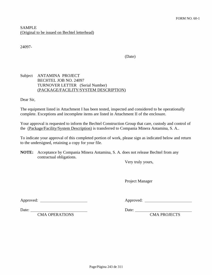
Page/Página 243 de 311
FORM NO. 60-1
SAMPLE(Original to be issued on Bechtel letterhead)
24097-
(Date)
Subject ANTAMINA PROJECTBECHTEL JOB NO. 24097TURNOVER LETTER (Serial Number)(PACKAGE/FACILITY/SYSTEM DESCRIPTION)
Dear Sir,
The equipment listed in Attachment I has been tested, inspected and considered to be operationallycomplete. Exceptions and incomplete items are listed in Attachment II of the enclosure.
Your approval is requested to inform the Bechtel Construction Group that care, custody and control ofthe (Package/Facility/System Description) is transferred to Compania Minera Antamina, S. A..
To indicate your approval of this completed portion of work, please sign as indicated below and returnto the undersigned, retaining a copy for your file.
NOTE: Acceptance by Compania Minera Antamina, S. A. does not release Bechtel from anycontractual obligations.
Very truly yours,
Project Manager
Approved: Approved:
Date: Date: CMA OPERATIONS CMA PROJECTS
Page/Página 244 de 311
FORM NO. 60-2Sample(Original to be issued on white bond)
Subject: ANTAMINA PROJECT BECHTEL JOB NO. 24097 TURNOVER LETTER (Serial Number) (PACKAGE/FACILITY/SYSTEM DESCRIPTION)
ATTACHMENT I
Operably Complete Equipment
Item Description
(1) (Equipment No. and Description)

Page/Página 245 de 311
FORM NO. 60-3
Sample(Original to be issued on white bond)
Subject: ANTAMINA PROJECT BECHTEL JOB NO. 24097 TURNOVER LETTER (Serial Number) (PACKAGE/FACILITY/SYSTEM DESCRIPTION)
ATTACHMENT II
Exceptions and/or Incomplete Items:
Item Description
(1) (Equipment No. and Description)

Page/Página 246 de 311
PARTE VI ANEXOS
FORMULARIO N° DESCRIPCION
01 CERTIFICADO DE AUTORIZACION PARA COMENZAR LAS PRUEBAS02 RESUMEN DE ACTIVIDADES DIARIAS DEL PROVEEDOR03 HOJA DE TIEMPO DEL PROVEEDOR04 NOTIFICACION DE FIN DE SERVICIO DEL PROVEEDOR05 AVISO DE CAMBIO DE PLANOS06 REGISTRO DE LUBRICACION DE EQUIPO MECANICO07 CERTIFICADO DE FINALIZACION DE PRUEBAS PREOPERACIONALES08 CERTIFICADO DE PRUEBAS DE TUBERIAS09 REGISTRO DE PRUEBAS HIDROSTATICAS DE ESTANQUES10 REGISTRO DE ALINEAMIENTO DE ACOPLAMIENTO DE EQUIPO
MECANICO11 REGISTRO DE ALINEAMIENTO DE MECANISMO DE ACCIONAMIENTO
POR CORREA/CADENA DE EQUIPO12 REGISTRS DE PRUEBAS PARA EQUIPOS MECANICOS13 REGISTRO DE PRUEBA DE MEGOHMMETRO14 REGISTRO DE PRUEBA DE AISLACION DE CABLE15 REGISTRO DE PRUEBA DE TRANSFORMADOR16 REGISTRO DE PRUEBAS DE AISLACION/RESISTENCIA DE BARRA
COLECTORA DE EQUIPO17 REGISTRO DE CALIBRACION DE RELE18-1 a 4 REGISTRO DE PRUEBAS DE CONTACTOR DE MOTOR DE MEDIO
VOLTAJE19-1 & 2 REGISTRO DE PRUEBA DE CONTACTOR DE MOTOR DE 480V20 REGISTRO DE PRUEBAS DE MOTOR JAULA DE ARDILLA21-1 & 21-2 REGISTRO DE PRUEBAS DE MOTOR DE ROTOR DEVANADO22 FORMATO DE PROGRAMA DE SECUENCIA DE PRUEBAS23 REGISTRO DE PRUEBAS DE CALIBRACION DE
TRANSMISOR/TRANSDUCTOR24 REGISTRO DE PRUEBAS DE CALIBRACION DE INTERRUPTOR ACTIVADO
POR PROCESO25 REGISTRO DE PRUEBAS DE VALVULA DE CONTROL26 REGISTRO DE PRUEBAS DE INDICADOR LOCAL27 REGISTRO DE PRUEBAS DE ANUNCIADOR28 REGISTRO DE PRUEBAS DE CAAV BALANCEADA (HVAC)29 REGISTRO DE PRUEBAS DE VALVULA DE CONTROL OPERADA POR
MOTOR30 REGISTRO DE PRUEBAS HIDROSTATICAS DE ESTANQUE
Page/Página 247 de 311
3132 REGISTRO DE PRUEBAS DE RESISTENCIA A CONEXION A TIERRA33 REGISTRO DE PRUEBA DE MOTOR3435 REGISTRO DE PRUEBAS DE TORRE DE TENDIDO AEREO36 REGISTRO DE PRUEBAS DE TRANSFORMADOR DE CORRIENTE37 REGISTRO DE PRUEBAS DE AMPERIMETRO Y VOLTIMETRO38-1 & 2 REGISTRO DE PRUEBAS DE INTERRUPTOR DE CIRCUITO DE MEDIO
VOLTAJE39-1 & 2 REGISTRO DE PRUEBAS DE INTERRUPTOR DE CIRCUITO EN AIRE DE
BAJO VOLTAJE40 REGISTRO DE PUREBAS DE CENTRO DE CONTROL DE MOTOR41-1 & 2 REGISTRO DE PRUEBAS DE INTERRUPTOR DE DESCONEXION DE AIRE42-1, 2 & 3 REGISTRO DE PRUEBAS DE MOTOR SINCRONICO43 PERMISO DE ACCESO DEL PROPIETARIO44 HOJA DE PRUEBAS DE CIRCUITO DE INSTRUMENTOS45 PRUEBA DE RESISTENCIA DE CONTACTO DE BARRAS COLECTORAS46 REGISTRO DE PRUEBA DE RIGIDEZ DIELECTRICA DE ACEITE PARA
TRANSFORMADORES47 REGISTRO DE PRUEBA DE DISTRIBUCION ELECTRICA48 CALIBRACION DE INSTRUMENTOS49 HOJA DE VERIFICACION DE CIRCUITO ANALOGICO50 REGISTRO DE PRUEBA DE CAAV BALANCEADA (HVAC)51 REGISTRO DE PRUEBA ADICIONAL DE CIRCUITO60-1 CARTA DE ENTREGA60-2 CARTA DE ENTREGA – ANEXO I60-3 CARTA DE ENTREGA – ANEXO II
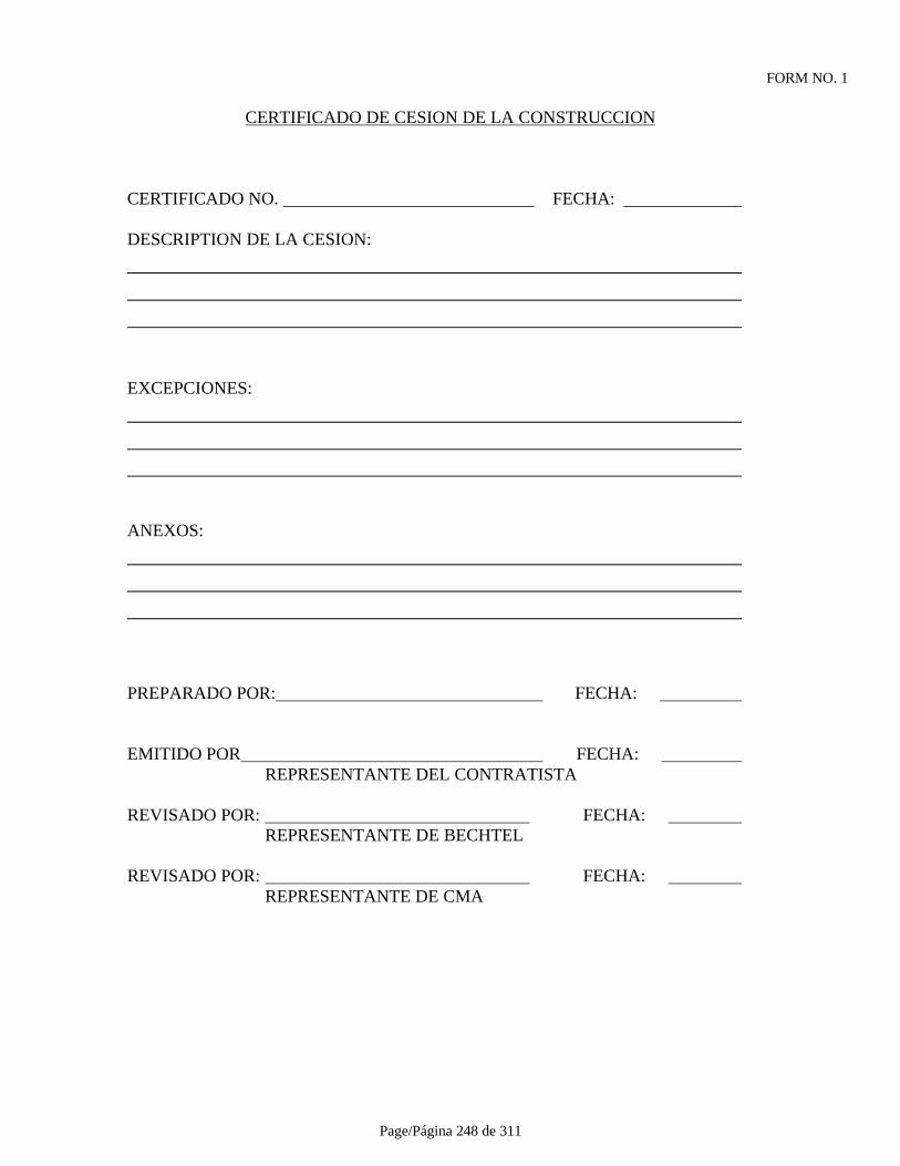
Page/Página 248 de 311
FORM NO. 1
CERTIFICADO DE CESION DE LA CONSTRUCCION
CERTIFICADO NO. FECHA:
DESCRIPTION DE LA CESION:
EXCEPCIONES:
ANEXOS:
PREPARADO POR: FECHA:
EMITIDO POR FECHA: REPRESENTANTE DEL CONTRATISTA
REVISADO POR: FECHA: REPRESENTANTE DE BECHTEL
REVISADO POR: FECHA: REPRESENTANTE DE CMA
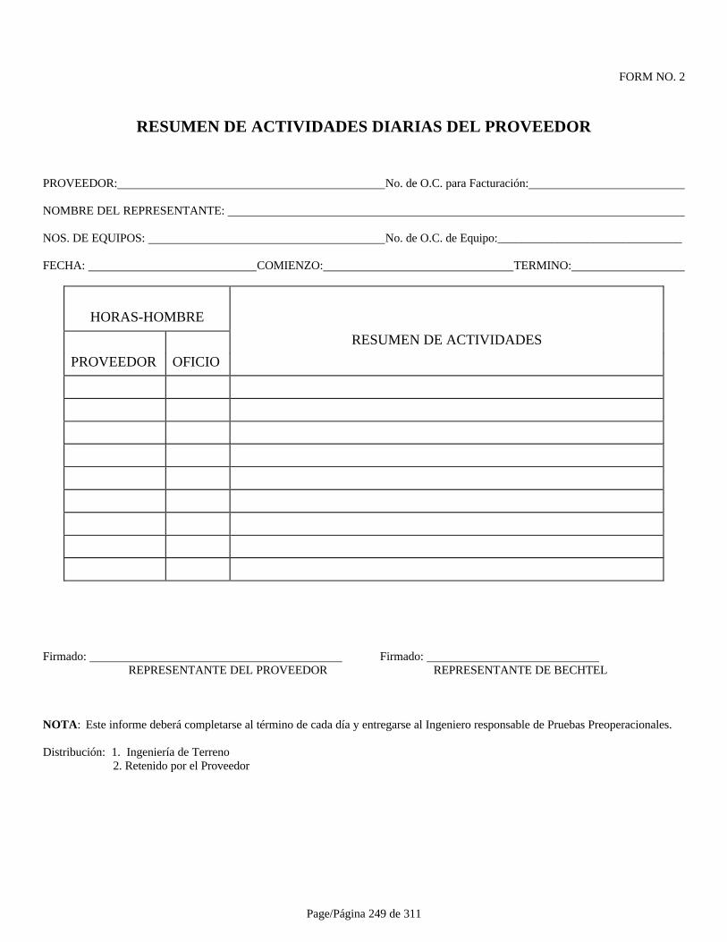
Page/Página 249 de 311
FORM NO. 2
RESUMEN DE ACTIVIDADES DIARIAS DEL PROVEEDOR
PROVEEDOR: No. de O.C. para Facturación:
NOMBRE DEL REPRESENTANTE:
NOS. DE EQUIPOS: No. de O.C. de Equipo:_______________________________
FECHA: COMIENZO: TERMINO:
HORAS-HOMBRE
RESUMEN DE ACTIVIDADES
PROVEEDOR OFICIO
Firmado: Firmado: REPRESENTANTE DEL PROVEEDOR REPRESENTANTE DE BECHTEL
NOTA: Este informe deberá completarse al término de cada día y entregarse al Ingeniero responsable de Pruebas Preoperacionales.
Distribución: 1. Ingeniería de Terreno 2. Retenido por el Proveedor
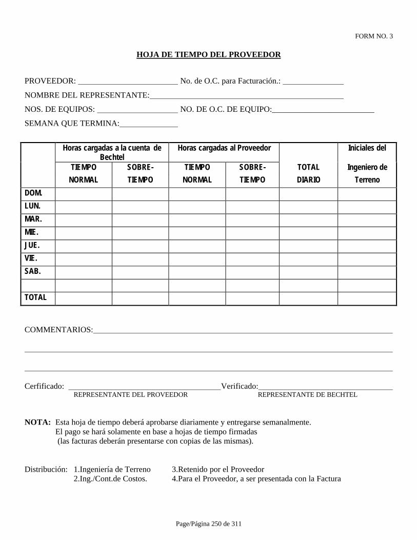
Page/Página 250 de 311
FORM NO. 3
HOJA DE TIEMPO DEL PROVEEDOR
PROVEEDOR: No. de O.C. para Facturación.:
NOMBRE DEL REPRESENTANTE:
NOS. DE EQUIPOS: NO. DE O.C. DE EQUIPO:_________________________
SEMANA QUE TERMINA:
Horas cargadas a la cuenta deBechtel
Horas cargadas al Proveedor Iniciales del
TIEMPO SOBRE- TIEMPO SOBRE- TOTAL Ingeniero de
NORMAL TIEMPO NORMAL TIEMPO DIARIO Terreno
DOM.
LUN.
MAR.
MIE.
JUE.
VIE.
SAB.
TOTAL
COMMENTARIOS:
Cerfificado: Verificado: REPRESENTANTE DEL PROVEEDOR REPRESENTANTE DE BECHTEL
NOTA: Esta hoja de tiempo deberá aprobarse diariamente y entregarse semanalmente. El pago se hará solamente en base a hojas de tiempo firmadas (las facturas deberán presentarse con copias de las mismas).
Distribución: 1.Ingeniería de Terreno 3.Retenido por el Proveedor 2.Ing./Cont.de Costos. 4.Para el Proveedor, a ser presentada con la Factura
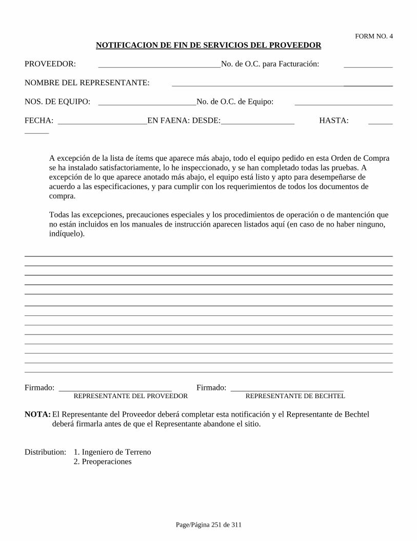
Page/Página 251 de 311
FORM NO. 4NOTIFICACION DE FIN DE SERVICIOS DEL PROVEEDOR
PROVEEDOR: No. de O.C. para Facturación:
NOMBRE DEL REPRESENTANTE: ____________
NOS. DE EQUIPO: No. de O.C. de Equipo:
FECHA: EN FAENA: DESDE: HASTA:
A excepción de la lista de ítems que aparece más abajo, todo el equipo pedido en esta Orden de Comprase ha instalado satisfactoriamente, lo he inspeccionado, y se han completado todas las pruebas. Aexcepción de lo que aparece anotado más abajo, el equipo está listo y apto para desempeñarse deacuerdo a las especificaciones, y para cumplir con los requerimientos de todos los documentos decompra.
Todas las excepciones, precauciones especiales y los procedimientos de operación o de mantención queno están incluidos en los manuales de instrucción aparecen listados aquí (en caso de no haber ninguno, indíquelo).
Firmado: Firmado: REPRESENTANTE DEL PROVEEDOR REPRESENTANTE DE BECHTEL
NOTA: El Representante del Proveedor deberá completar esta notificación y el Representante de Bechteldeberá firmarla antes de que el Representante abandone el sitio.
Distribution: 1. Ingeniero de Terreno2. Preoperaciones

Page/Página 252 de 311
FORM NO. 5
PAQUETE PRE-OP NO:
INSTALACION/EQUIPO NO:
NOTIFICACION DE CAMBIO EN EL TERRENO
A: FECHA:
FCN (Aviso de cambio de diseño) NO.: ____________
Medida de Acción Correctiva:
Originador:
Inspeccionado por: Representante de Bechtel
Aprobado por: Representante de CMA
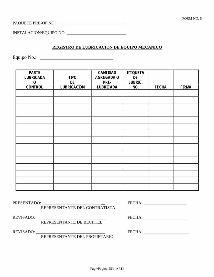
Page/Página 253 de 311
FORM NO. 6PAQUETE PRE-OP.NO:
INSTALACION/EQUIPO NO:
REGISTRO DE LUBRICACION DE EQUIPO MECANICO
Equipo No.:
PARTE CANTIDAD ETIQUETALUBRICADA TIPO AGREGADA O DE
O DE PRE- LUBRIC.CONTROL LUBRICACION LUBRICADA NO. FECHA FIRMA
PRESENTADO: __ FECHA: REPRESENTANTE DEL CONTRATISTA
REVISADO: _______________________________ FECHA: REPRESENTANTE DE BECHTEL
REVISADO: _________________________________ FECHA: REPRESENTANTE DEL PROPIETARIO
Page/Página 254 de 311
FORM NO. 7
CERTIFICADO DE FINALIZACION DE PRUEBAS PREOPERACIONALES
CERTIFICADO NO.: FECHA:
___________________ ____________________________REPRESENTANTE DE BECHTEL REPRESENTANTE DEL PROPIETARIO

Page/Página 255 de 311
FORM NO. 8PAQUETE PRE-OP.NO:
INSTALACION/EQUIPO NO:
CERTIFICADO DE PRUEBAS DE TUBERIAS
LINEA NO.:
DESDE/A:
P & ID NO.:
ISOMETRICO NO.:
MEDIO DE LAVADO A PRESION: BOMBEADO/GRAVEDAD:
EQUIPO USADO:
MEDIO DE PRUEBA DE PRESION:
PRESION DE PRUEBA ESPECIFICADO:
DURACION ESPECIFICADA:
PRESION DE PRUEBA REAL:
DURACION REAL:
DETECTOR DE FILTRACIONES USADO:
COMENTARIOS:
EJECUTADA POR: FECHA: REPRESENTANTE DEL CONTRATISTA
REVISADA POR: FECHA: REPRESENTANTE DE BECHTEL
REVISADA POR: FECHA: REPRESENTANTE DE CMA
Page/Página 256 de 311
FORM NO. 9PAQUETE PRE-OP.NO:
INSTALACION/EQUIPO NO:
REGISTRO DE PRUEBAS HIDROSTATICAS DE TANQUE
Medio de Prueba: Presión: :
Resultados de Prueba:
Observaciones:
EJECUTADA POR: FECHA: REPRESENTANTE DEL CONTRATISTA
REVISADA POR: FECHA: REPRESENTANTE DE BECHTEL
REVISADA POR: FECHA: REPRESENTANTE DE CMA
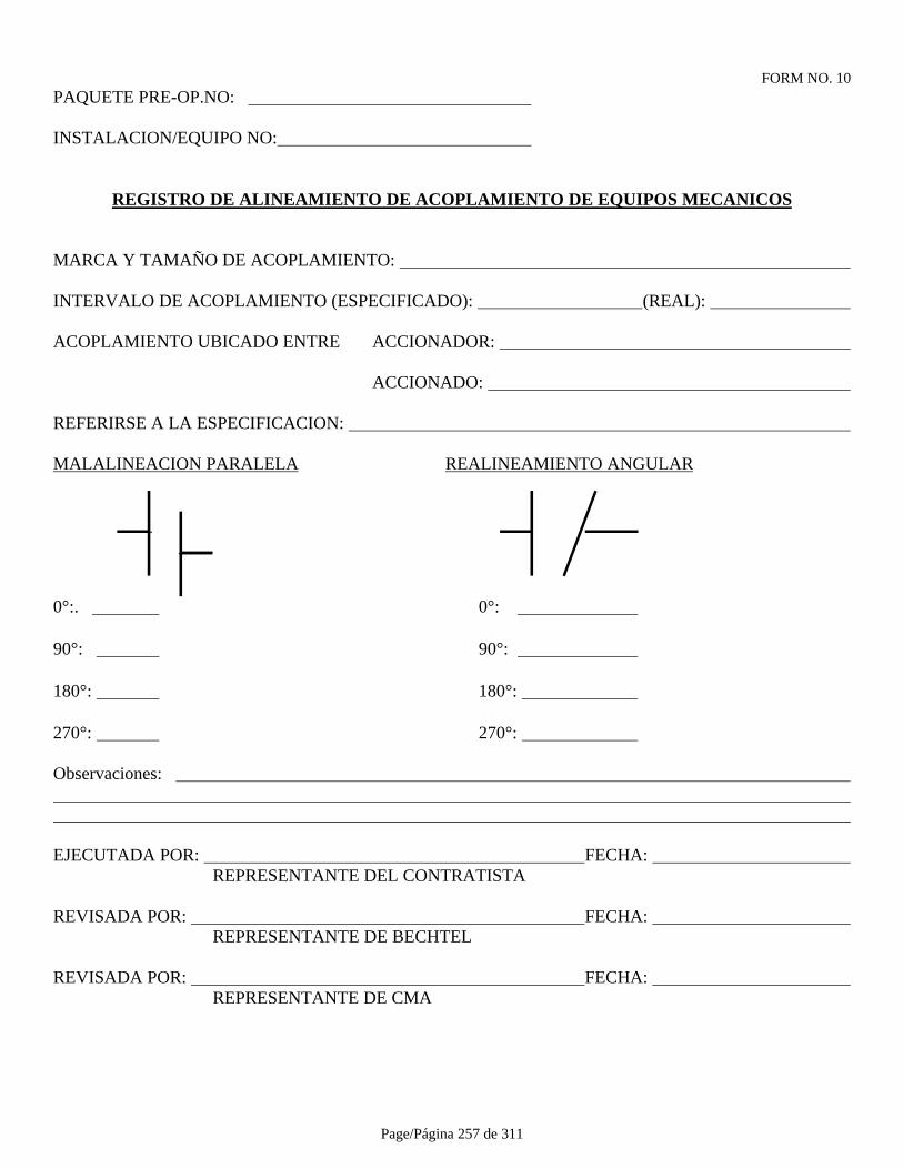
Page/Página 257 de 311
FORM NO. 10PAQUETE PRE-OP.NO:
INSTALACION/EQUIPO NO:
REGISTRO DE ALINEAMIENTO DE ACOPLAMIENTO DE EQUIPOS MECANICOS
MARCA Y TAMAÑO DE ACOPLAMIENTO:
INTERVALO DE ACOPLAMIENTO (ESPECIFICADO): (REAL):
ACOPLAMIENTO UBICADO ENTRE ACCIONADOR:
ACCIONADO:
REFERIRSE A LA ESPECIFICACION:
MALALINEACION PARALELA REALINEAMIENTO ANGULAR
0°:. 0°:
90°: 90°:
180°: 180°:
270°: 270°:
Observaciones:
EJECUTADA POR: FECHA: REPRESENTANTE DEL CONTRATISTA
REVISADA POR: FECHA: REPRESENTANTE DE BECHTEL
REVISADA POR: FECHA: REPRESENTANTE DE CMA
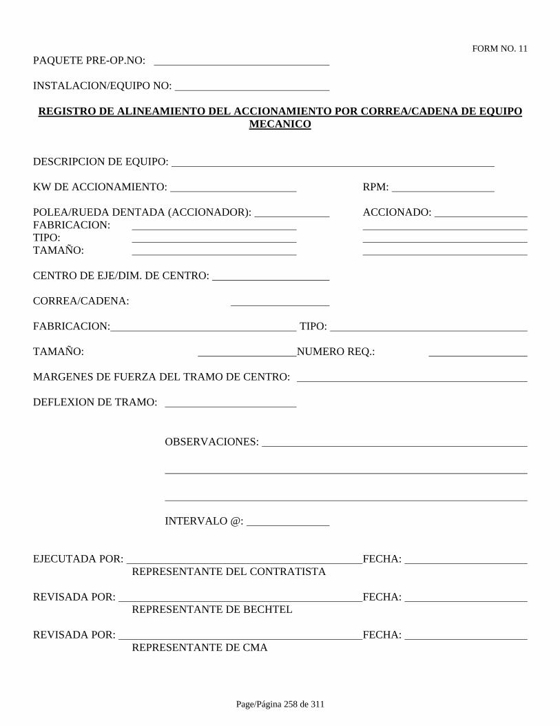
Page/Página 258 de 311
FORM NO. 11PAQUETE PRE-OP.NO:
INSTALACION/EQUIPO NO:
REGISTRO DE ALINEAMIENTO DEL ACCIONAMIENTO POR CORREA/CADENA DE EQUIPOMECANICO
DESCRIPCION DE EQUIPO:
KW DE ACCIONAMIENTO: RPM:
POLEA/RUEDA DENTADA (ACCIONADOR): ACCIONADO: FABRICACION: TIPO: TAMAÑO:
CENTRO DE EJE/DIM. DE CENTRO:
CORREA/CADENA:
FABRICACION: TIPO:
TAMAÑO: NUMERO REQ.:
MARGENES DE FUERZA DEL TRAMO DE CENTRO:
DEFLEXION DE TRAMO:
OBSERVACIONES:
INTERVALO @:
EJECUTADA POR: FECHA: REPRESENTANTE DEL CONTRATISTA
REVISADA POR: FECHA: REPRESENTANTE DE BECHTEL
REVISADA POR: FECHA: REPRESENTANTE DE CMA
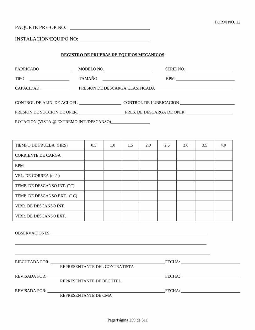
Page/Página 259 de 311
FORM NO. 12PAQUETE PRE-OP.NO:
INSTALACION/EQUIPO NO:
REGISTRO DE PRUEBAS DE EQUIPOS MECANICOS
FABRICADO MODELO NO. SERIE NO.
TIPO TAMAÑO RPM
CAPACIDAD PRESION DE DESCARGA CLASIFICADA
CONTROL DE ALIN. DE ACLOPL. CONTROL DE LUBRICACION
PRESION DE SUCCION DE OPER. PRES. DE DESCARGA DE OPER.
ROTACION (VISTA @ EXTREMO INT./DESCANSO)
TIEMPO DE PRUEBA (HRS) 0.5 1.0 1.5 2.0 2.5 3.0 3.5 4.0
CORRIENTE DE CARGA
RPM
VEL. DE CORREA (m./s)
TEMP. DE DESCANSO INT. (o C)
TEMP. DE DESCANSO EXT. (o C)
VIBR. DE DESCANSO INT.
VIBR. DE DESCANSO EXT.
OBSERVACIONES
EJECUTADA POR: FECHA: REPRESENTANTE DEL CONTRATISTA
REVISADA POR: FECHA: REPRESENTANTE DE BECHTEL
REVISADA POR: FECHA: REPRESENTANTE DE CMA
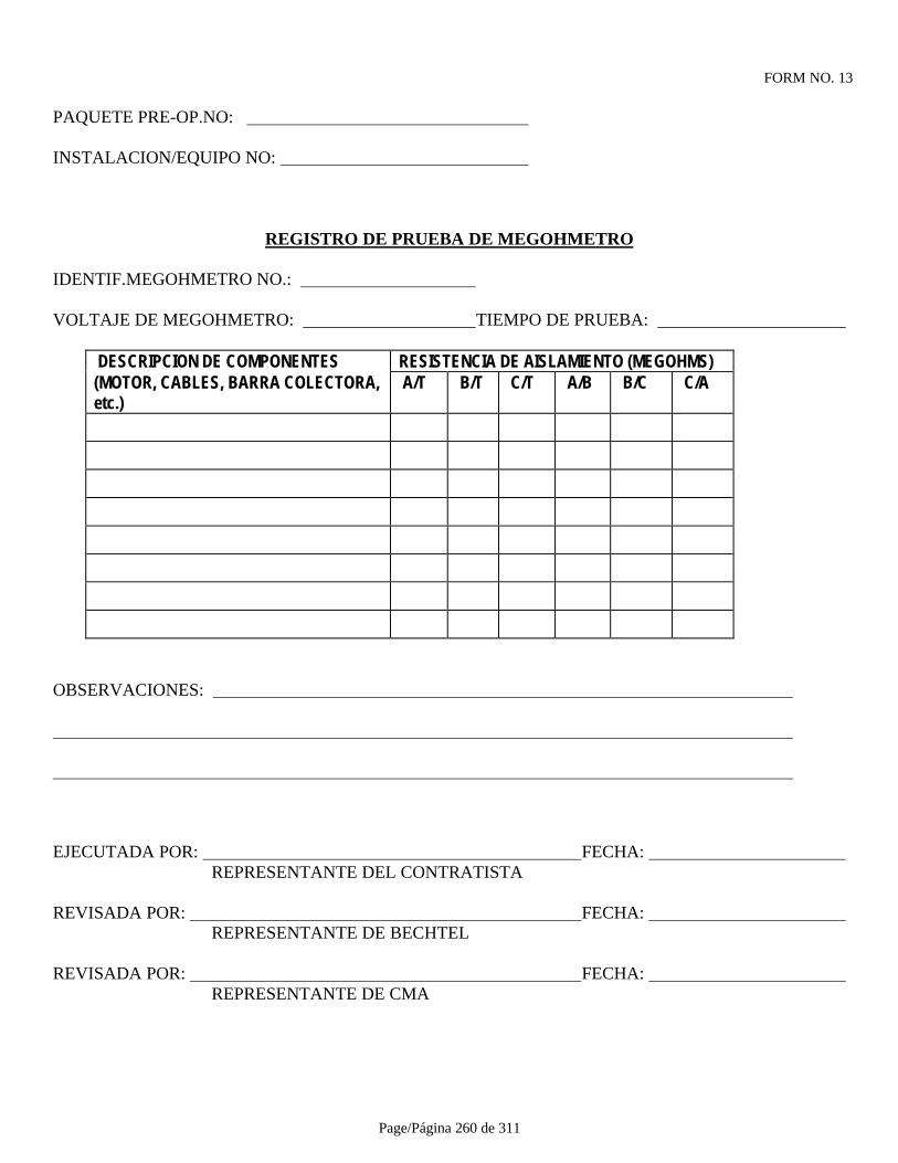
Page/Página 260 de 311
FORM NO. 13
PAQUETE PRE-OP.NO:
INSTALACION/EQUIPO NO:
REGISTRO DE PRUEBA DE MEGOHMETRO
IDENTIF.MEGOHMETRO NO.:
VOLTAJE DE MEGOHMETRO: TIEMPO DE PRUEBA:
DESCRIPCION DE COMPONENTES RESISTENCIA DE AISLAMIENTO (MEGOHMS)(MOTOR, CABLES, BARRA COLECTORA,etc.)
A/T B/T C/T A/B B/C C/A
OBSERVACIONES:
EJECUTADA POR: FECHA: REPRESENTANTE DEL CONTRATISTA
REVISADA POR: FECHA: REPRESENTANTE DE BECHTEL
REVISADA POR: FECHA: REPRESENTANTE DE CMA
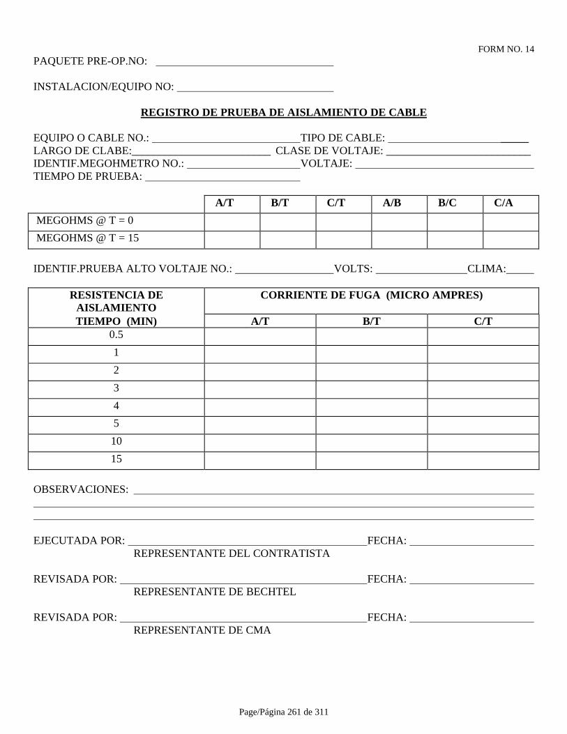
Page/Página 261 de 311
FORM NO. 14PAQUETE PRE-OP.NO:
INSTALACION/EQUIPO NO:
REGISTRO DE PRUEBA DE AISLAMIENTO DE CABLE
EQUIPO O CABLE NO.: TIPO DE CABLE: _____LARGO DE CLABE:_________________________ CLASE DE VOLTAJE: __________________________IDENTIF.MEGOHMETRO NO.: VOLTAJE: TIEMPO DE PRUEBA:
A/T B/T C/T A/B B/C C/A
MEGOHMS @ T = 0
MEGOHMS @ T = 15
IDENTIF.PRUEBA ALTO VOLTAJE NO.: VOLTS: CLIMA:
RESISTENCIA DEAISLAMIENTO
CORRIENTE DE FUGA (MICRO AMPRES)
TIEMPO (MIN) A/T B/T C/T0.5
1
2
3
4
5
10
15
OBSERVACIONES:
EJECUTADA POR: FECHA: REPRESENTANTE DEL CONTRATISTA
REVISADA POR: FECHA: REPRESENTANTE DE BECHTEL
REVISADA POR: FECHA: REPRESENTANTE DE CMA

Page/Página 262 de 311
FORM NO. 15PAQUETE PRE-OP.NO:
INSTALACION/EQUIPO NO:
REGISTRO DE PRUEBA DE TRANSFORMADOR
Equipo No.: ______________________________________________________________________Descripción: _________________________________________________________________________
Fabricación.: Tipo: Clasificación AV: BV Hz Serie No.: Enfriamiento: Diagrama Unilineal/ Referencia Plano: ______
Resistencia de Aislación:Megger Identif. No.: Voltaje de Megger: Tiempo de prueba: HV/E (M-ohms ) LV/E (M-ohms ) HV/LV (M-ohms ) Con.a tierra (ohms): ____________
Interruptor primario: Tarado de Interruptor: Ajuste de Disparo:
Voltaje Primario A/B B/C C/A________ _______ _______
Voltaje Secundario
Conexión A/B B/C C/A A/N B/N C/N_____ ______ _____ ______ ______ ______ ______
Observaciones:
EJECUTADA POR: FECHA: REPRESENTANTE DEL CONTRATISTA
REVISADA POR: FECHA: REPRESENTANTE DE BECHTEL
REVISADA POR: FECHA: REPRESENTANTE DE CMA

Page/Página 263 de 311
FORM NO. 16PAQUETE PRE-OP.NO:
INSTALACION/EQUIPO NO:
AISLACION DE BARRA COLECTORA DE EQUIPO / REGISTRO DE PRUEBA DE RESISTENCIA
Equipo Fabricación. Clasificación de Interrupción (MVA) Clase de Voltaje Barra Colectora Princ. (Amps) Barra Col.Aux. (Amps)
Diag. Unilineal No./Rev Plano de Trazado No./Rev
Mat.de Aisl.de Barra Col.Prin. Mat.de Aisl.de Barra Col.Aux. Mat.de Apolyo de Barra Col. Uniones de Barra Col. Continuidad de Barra Col. Humedad Relativa (%) Temp.de Aislación (°C)
Voltaje de Megóhmetro Mat.de Aisl.de Barra Col.Aux. Largo de Cable de Prueba (m) Mat.de Aisl.de Cable de Prueba Tamaño de Cond.de Cable de Pr. Protegido/No Protegido
Absorción Dieléctrica Polarización
Conexiones de Cablede Prueba
Megohms
30 Seg.
Megohms
60 Seg.
Megohms
30/60 Seg.
Megohms1
Min.
Megohms10
Min.
Razón deMin.10/1
Observaciones
EJECUTADA POR: FECHA: REPRESENTANTE DEL CONTRATISTA
REVISADA POR: FECHA: REPRESENTANTE DE BECHTEL
REVISADA POR: FECHA: REPRESENTANTE DE CMA
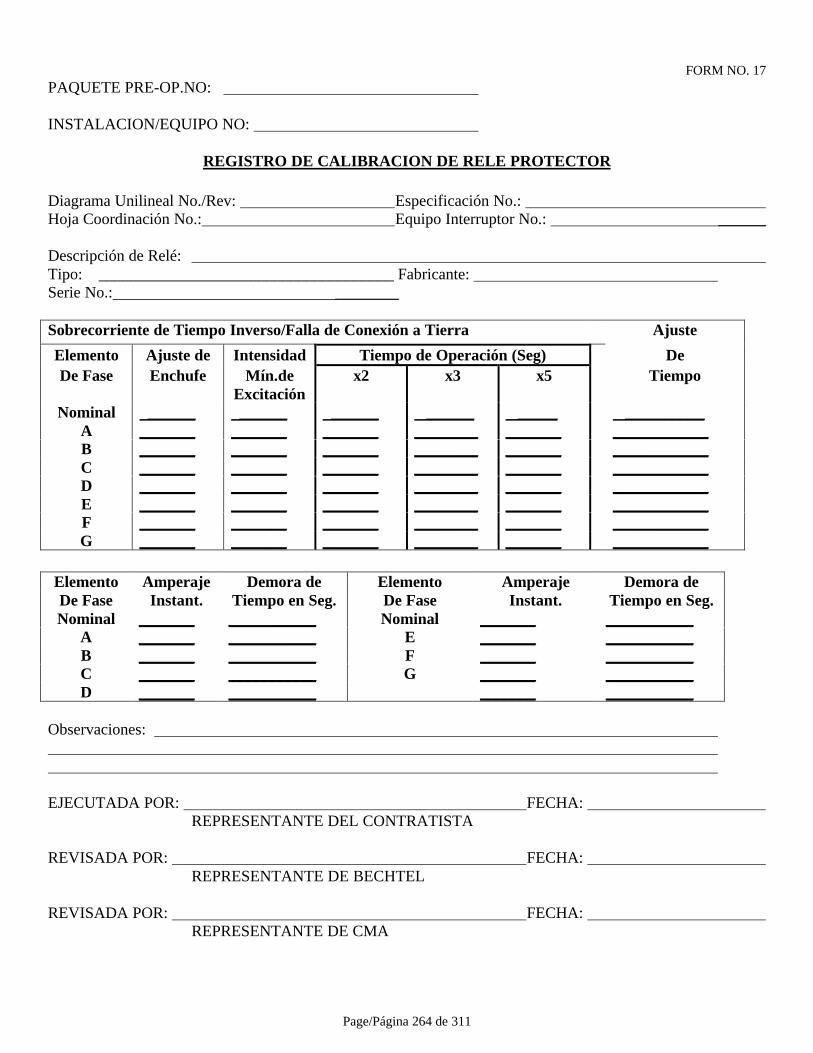
Page/Página 264 de 311
FORM NO. 17PAQUETE PRE-OP.NO:
INSTALACION/EQUIPO NO:
REGISTRO DE CALIBRACION DE RELE PROTECTOR
Diagrama Unilineal No./Rev: Especificación No.: Hoja Coordinación No.: Equipo Interruptor No.: ______
Descripción de Relé: Tipo: _____________________________________ Fabricante: Serie No.: ________
Sobrecorriente de Tiempo Inverso/Falla de Conexión a Tierra Ajuste
Elemento Ajuste de Intensidad Tiempo de Operación (Seg) DeDe Fase Enchufe Mín.de
Excitaciónx2 x3 x5 Tiempo
Nominal ______ ______ ______ ______ _____ __________A _______ _______ _______ ________ _______ ____________B _______ _______ _______ ________ _______ ____________C _______ _______ _______ ________ _______ ____________D _______ _______ _______ ________ _______ ____________E _______ _______ _______ ________ _______ ____________F _______ _______ _______ ________ _______ ____________G _______ _______ _______ ________ _______ ____________
Elemento Amperaje Demora de Elemento Amperaje Demora deDe Fase Instant. Tiempo en Seg. De Fase Instant. Tiempo en Seg.Nominal _______ ___________ Nominal _______ ___________
A _______ ___________ E _______ ___________B _______ ___________ F _______ ___________C _______ ___________ G _______ ___________D _______ ___________ _______ ___________
Observaciones:
EJECUTADA POR: FECHA: REPRESENTANTE DEL CONTRATISTA
REVISADA POR: FECHA: REPRESENTANTE DE BECHTEL
REVISADA POR: FECHA: REPRESENTANTE DE CMA

Page/Página 265 de 311
FORM NO. 18-1PAQUETE PRE-OP.NO:
INSTALACION/EQUIPO NO:
REGISTRO DE PRUEBA DE CONTACTOR DE MOTOR DE MEDIO VOLTAJE
CCM No.: Cubículo No.: Contactor No.:
Motor No.: kW de Motor : Clasif.de Contactor:
Clasif. Aisl.: Clasif. S/C: Voltaje de Control:
Corr.Plena Carga de Motor: Prueba S/C/: Para % Carga
Tipo de Termistor Resistencia de Oper.
Diagrama Unilineal No./Rev.:
Esquema de Control No./Rev: Esquema de Arrancador No./Rev.
Unidad de Fusible de Interruptor:
Inspección Visual
Conexiones Eléctricas
Operación del Mecanismo
Operación de Enclavamiento Mecánico
Operación de Enclavamiento Eléctrico
Clasificación de Fusibles
Carro del Contactor:
Alineamiento de Rieles del Carro Cargador
Operación del Carro Cargador
Operación del Mecanismo de Retiro
Operación del Mecanismo de Cierre
Operación del Mecanismo de Aislación
Operación del Mecanismo de Conexión a Tierra
Operación de Enclavamiento del Mecanismo
Operación de Enclavamiento Eléctrico
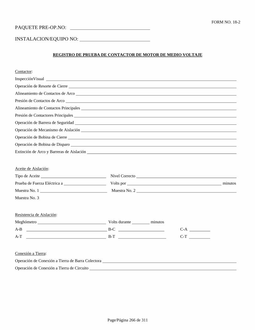
Page/Página 266 de 311
FORM NO. 18-2PAQUETE PRE-OP.NO:
INSTALACION/EQUIPO NO:
REGISTRO DE PRUEBA DE CONTACTOR DE MOTOR DE MEDIO VOLTAJE
Contactor:
InspecciónVisual
Operación de Resorte de Cierre
Alineamiento de Contactos de Arco
Presión de Contactos de Arco
Alineamiento de Contactos Principales
Presión de Contactores Principales
Operación de Barrera de Seguridad
Operación de Mecanismo de Aislación
Operación de Bobina de Cierre
Operación de Bobina de Disparo
Extinción de Arco y Barreras de Aislación
Aceite de Aislación:
Tipo de Aceite Nivel Correcto
Prueba de Fuerza Eléctrica a Volts por minutos
Muestra No. 1 Muestra No. 2
Muestra No. 3
Resistencia de Aislación:
Meghómetro Volts durante minutos
A-B B-C C-A
A-T B-T C-T
Conexión a Tierra:
Operación de Conexión a Tierra de Barra Colectora
Operación de Conexión a Tierra de Circuito

Page/Página 267 de 311
FORM NO. 18-3PAQUETE PRE-OP.NO:
INSTALACION/EQUIPO NO:
REGISTRO DE PRUEBA DE CONTACTOR DE MOTOR DE MEDIO VOLTAJE
Relés Auxiliares:
Inspección Visual
Conexiones Eléctricas
Operación Mecánica de Contactos
Operación de Mecanismos de Relés
Continuidad de Cableado de Control
Operación de Relés en Posición de Prueba
Operación de Relés en Posición de Servicio
Clasificación de Fusibles de Control
Sistema de Medición y de Protección:
Inspección Visual
Conexiones Eléctricas
Razón de Transf. de Corr. de Prot. A B C
Razón de Transf. de Corr. de Medid. A B C
Razón de Transf. de Corr. de Núcleo Balanceado
Razón de Transf. de Corr. de Fuga de Tierra
Control de Polaridad de Transf. de Corr. – “Flick Test”:
Fase Protección Medición
A B C
Núcleo Balanceado Fuga de Tierra

Page/Página 268 de 311
FORM NO. 18-4PAQUETE PRE-OP.NO:
INSTALACION/EQUIPO NO:
REGISTRO DE PRUEBA DE CONTACTOR DE MOTOR DE MEDIO VOLTAJE
Razón de Transf.de Pot.de Med. Serie No.
Razón de Transf.de Pot.de Prot. Serie No.
Resistencia de Aislación Tiempo de Prueba de Megóhm.
Medición Protección
AV/T (Volts/M-ohms)
AV/T (Volts/M-ohms)
AV/BV (Volts/M-ohms)
Continuidad de Cableado de Disparo:
Operación de Circuito de Disparo:
EJECUTADA POR: FECHA: REPRESENTANTE DEL CONTRATISTA
REVISADA POR: FECHA: REPRESENTANTE DE BECHTEL
REVISADA POR: FECHA: REPRESENTANTE DE CMA
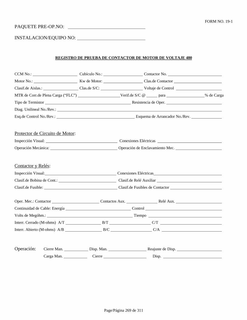
Page/Página 269 de 311
FORM NO. 19-1PAQUETE PRE-OP.NO:
INSTALACION/EQUIPO NO:
REGISTRO DE PRUEBA DE CONTACTOR DE MOTOR DE VOLTAJE 480
CCM No.: Cubículo No.: Contactor No.
Motor No.: Kw de Motor: Clas.de Contactor
Clasif.de Aislas.: Clas.de S/C: Voltaje de Control
MTR de Corr.de Plena Carga (“FLC”) Verif.de S/C @ para % de Carga
Tipo de Termistor Resistencia de Oper.
Diag. Unilineal No./Rev.:
Esq.de Control No./Rev.: Esquema de Arrancador No./Rev.
Protector de Circuito de Motor:
Inspección Visual: Conexiones Eléctricas
Operación Mecánica: Operación de Enclavamiento Mec.
Contactor y Relés:
Inspección Visual: Conexiones Eléctricas
Clasif.de Bobina de Cont.: Clasif.de Relé Auxiliar
Clasif.de Fusible: Clasif.de Fusibles de Contactor
Oper. Mec.: Contactor Contactos Aux. Relé Aux.
Continuidad de Cable: Energía Control
Volts de Megóhm.: Tiempo
Interr. Cerrado (M-ohms) A/T B/T C/T
Interr. Abierto (M-ohms) A/B B/C C/A
Operación: Cierre Man. Disp. Man. Reajuste de Disp.
Carga Man. Cierre Disp.
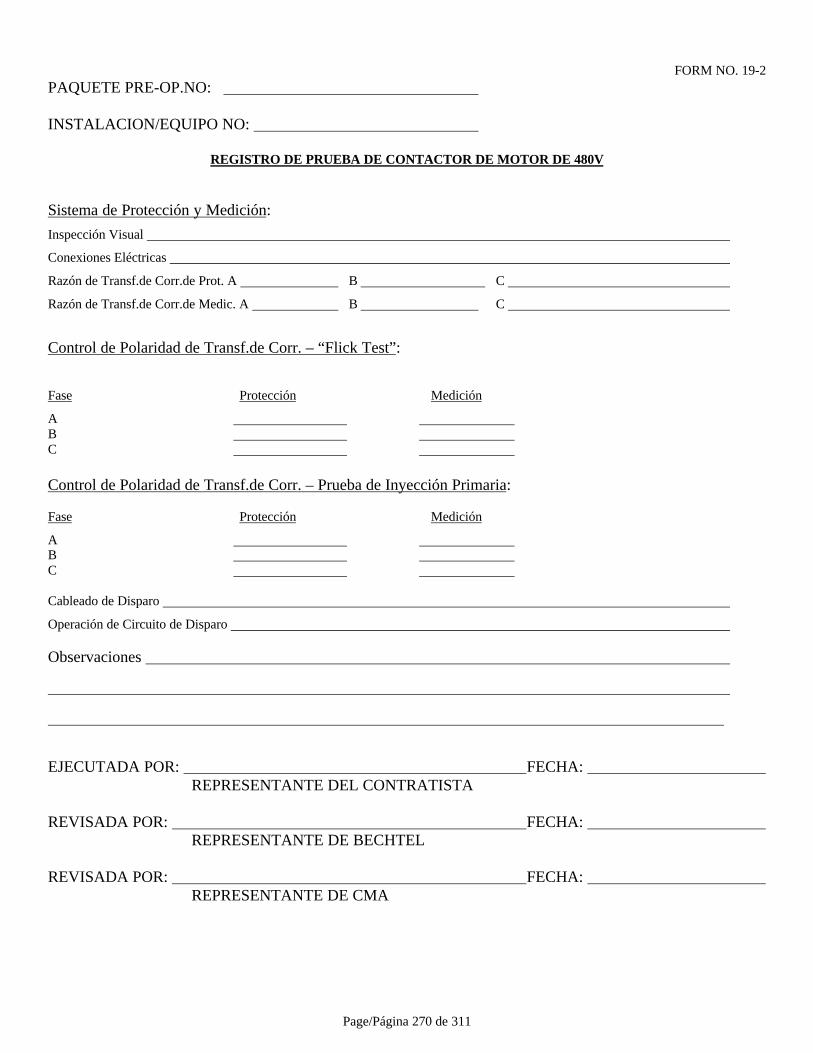
Page/Página 270 de 311
FORM NO. 19-2PAQUETE PRE-OP.NO:
INSTALACION/EQUIPO NO:
REGISTRO DE PRUEBA DE CONTACTOR DE MOTOR DE 480V
Sistema de Protección y Medición:
Inspección Visual
Conexiones Eléctricas
Razón de Transf.de Corr.de Prot. A B C
Razón de Transf.de Corr.de Medic. A B C
Control de Polaridad de Transf.de Corr. – “Flick Test”:
Fase Protección Medición
A B C
Control de Polaridad de Transf.de Corr. – Prueba de Inyección Primaria:
Fase Protección Medición
A B C
Cableado de Disparo
Operación de Circuito de Disparo
Observaciones
EJECUTADA POR: FECHA: REPRESENTANTE DEL CONTRATISTA
REVISADA POR: FECHA: REPRESENTANTE DE BECHTEL
REVISADA POR: FECHA: REPRESENTANTE DE CMA
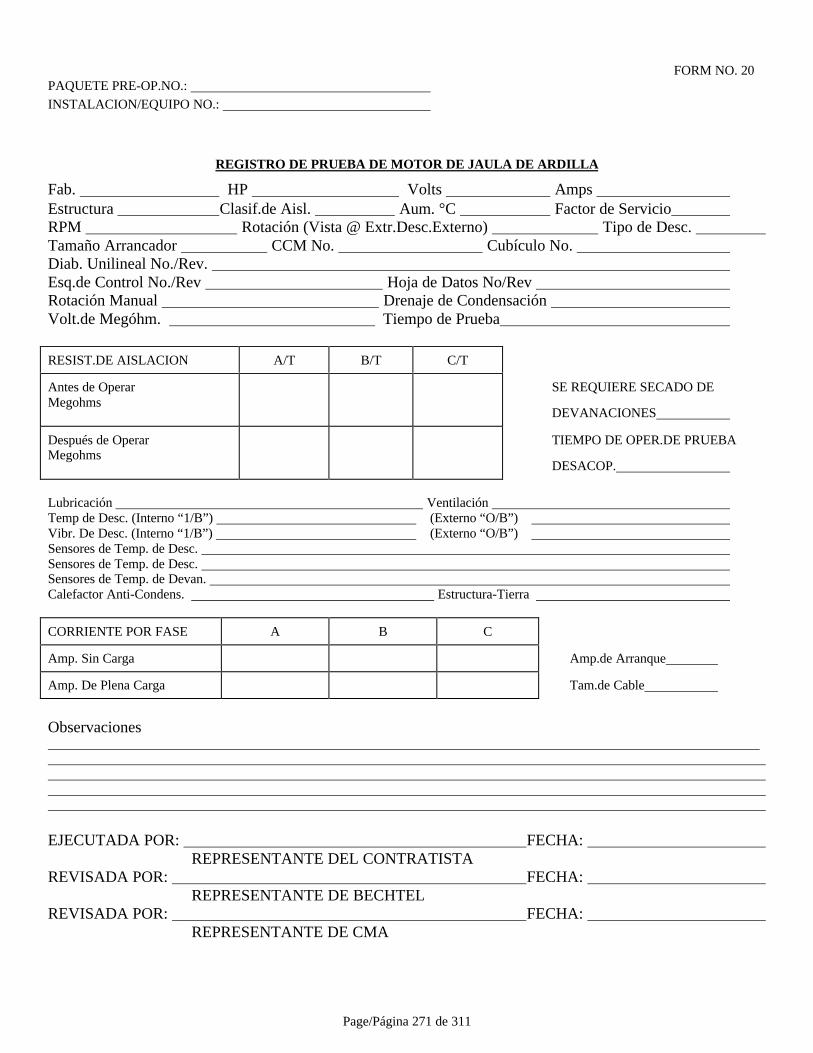
Page/Página 271 de 311
FORM NO. 20PAQUETE PRE-OP.NO.: INSTALACION/EQUIPO NO.:
REGISTRO DE PRUEBA DE MOTOR DE JAULA DE ARDILLA
Fab. HP Volts Amps Estructura Clasif.de Aisl. Aum. °C Factor de Servicio RPM Rotación (Vista @ Extr.Desc.Externo) Tipo de Desc. Tamaño Arrancador CCM No. Cubículo No. Diab. Unilineal No./Rev. Esq.de Control No./Rev Hoja de Datos No/Rev Rotación Manual Drenaje de Condensación Volt.de Megóhm. Tiempo de Prueba
RESIST.DE AISLACION A/T B/T C/T
Antes de OperarMegohms
SE REQUIERE SECADO DE
DEVANACIONES
Después de OperarMegohms
TIEMPO DE OPER.DE PRUEBA
DESACOP.
Lubricación Ventilación Temp de Desc. (Interno “1/B”) (Externo “O/B”) Vibr. De Desc. (Interno “1/B”) (Externo “O/B”) Sensores de Temp. de Desc. Sensores de Temp. de Desc. Sensores de Temp. de Devan. Calefactor Anti-Condens. Estructura-Tierra
CORRIENTE POR FASE A B C
Amp. Sin Carga Amp.de Arranque
Amp. De Plena Carga Tam.de Cable
Observaciones
EJECUTADA POR: FECHA: REPRESENTANTE DEL CONTRATISTA
REVISADA POR: FECHA: REPRESENTANTE DE BECHTEL
REVISADA POR: FECHA: REPRESENTANTE DE CMA
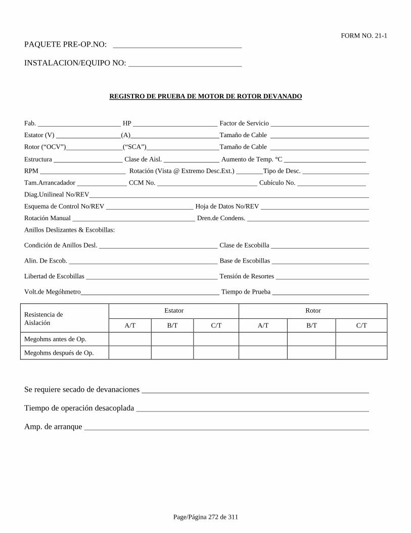
Page/Página 272 de 311
FORM NO. 21-1PAQUETE PRE-OP.NO:
INSTALACION/EQUIPO NO:
REGISTRO DE PRUEBA DE MOTOR DE ROTOR DEVANADO
Fab. HP Factor de Servicio
Estator (V) (A) Tamaño de Cable
Rotor (“OCV”) (“SCA”) Tamaño de Cable
Estructura Clase de Aisl. Aumento de Temp. °C
RPM Rotación (Vista @ Extremo Desc.Ext.) Tipo de Desc.
Tam.Arrancadador CCM No. Cubículo No.
Diag.Unilineal No/REV
Esquema de Control No/REV Hoja de Datos No/REV
Rotación Manual Dren.de Condens.
Anillos Deslizantes & Escobillas:
Condición de Anillos Desl. Clase de Escobilla
Alin. De Escob. Base de Escobillas
Libertad de Escobillas Tensión de Resortes
Volt.de Megóhmetro Tiempo de Prueba
Resistencia deEstator Rotor
Aislación A/T B/T C/T A/T B/T C/T
Megohms antes de Op.
Megohms después de Op.
Se requiere secado de devanaciones
Tiempo de operación desacoplada
Amp. de arranque

Page/Página 273 de 311
FORM NO. 21-2PAQUETE PRE-OP.NO:
INSTALACION/EQUIPO NO:
REGISTRO DE PRUEBA DE MOTOR DE ROTOR DEVANADO
Lubricación Ventilación
Temp. de Desc. (Interno) Externo
Vibr. De Desc. (Interno) Externo
Sensores de Temp. de Desc.
Sensores de Temp. de Devanaciones
Calefactor Anti-Condens.
Con. A Tierra de la Estructura
Amps. Sin Carga del Estator (A) (B) (C)
Observaciones
EJECUTADA POR: FECHA: REPRESENTANTE DEL CONTRATISTA
REVISADA POR: FECHA: REPRESENTANTE DE BECHTEL
REVISADA POR: FECHA: REPRESENTANTE DE CMA

Page/Página 274 de 311
FORM NO. 22
FORMATO DE PROGRAMA DE SECUENCIA DE PRUEBAS
1. Paquete Preop./Item No. (e.j.: 100-01-xxxx)
2. P&ID, Diagramas Unilineales, y Plano de Ref. No.
3. No. de Equipo/Descripción
4. Actividad de Prueba (véase más abajo)
5. Fecha Programada de Finalización (Fin de Semana o Semana del Proyecto No.)
6. Fecha Pronosticada de Finalización (Fin de Semana o Semana del Proyecto No.)
7. Fecha de Finalización Real
8. Fecha de Entrega
ACTIVIDADES DE PRUEBA
I - AislamientoC - CalibraciónCC - Circuito de ControlLC - Control de Circuito LoopP - Pruebas de Contención y Lavado a ChorroA - AlineamientoR - Operación Inicial (en vacío)IN - Inspección de Instalación

Page/Página 275 de 311
FORM NO. 23PAQUETE PRE-OP.NO:
INSTALACION/EQUIPO NO:
REGISTRO DE PRUEBA DE CALIBRACION DE TRANSMISOR/TRANSDUCTOR
Tipo Fabricación Serie No. Márgenes Tramo Elevación/Surpesión.
P&ID No. Hoja de Datos.No. Loop No. Det. Inst.. No.
Tipo de Equipo de Prueba # de Serie de Equipo de Prueba
% Entrada Entrada Unidad Salida Unidad +/- Situación Final Observaciones
Observaciones
EJECUTADA POR: FECHA: REPRESENTANTE DEL CONTRATISTA
REVISADA POR: FECHA: REPRESENTANTE DE BECHTEL
REVISADA POR: FECHA: REPRESENTANTE DE CMA
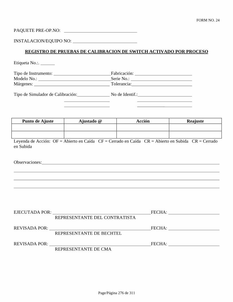
Page/Página 276 de 311
FORM NO. 24
PAQUETE PRE-OP.NO:
INSTALACION/EQUIPO NO:
REGISTRO DE PRUEBAS DE CALIBRACION DE SWITCH ACTIVADO POR PROCESO
Etiqueta No.:.
Tipo de Instrumento: Fabricación: Modelo No.: Serie No.: Márgenes: Tolerancia:
Tipo de Simulador de Calibración: No de Identif.: ____________
Punto de Ajuste Ajustado @ Acción Reajuste
Leyenda de Acción: OF = Abierto en Caída CF = Cerrado en Caída CR = Abierto en Subida CR = Cerradoen Subida
Observaciones:
EJECUTADA POR: FECHA: REPRESENTANTE DEL CONTRATISTA
REVISADA POR: FECHA: REPRESENTANTE DE BECHTEL
REVISADA POR: FECHA: REPRESENTANTE DE CMA
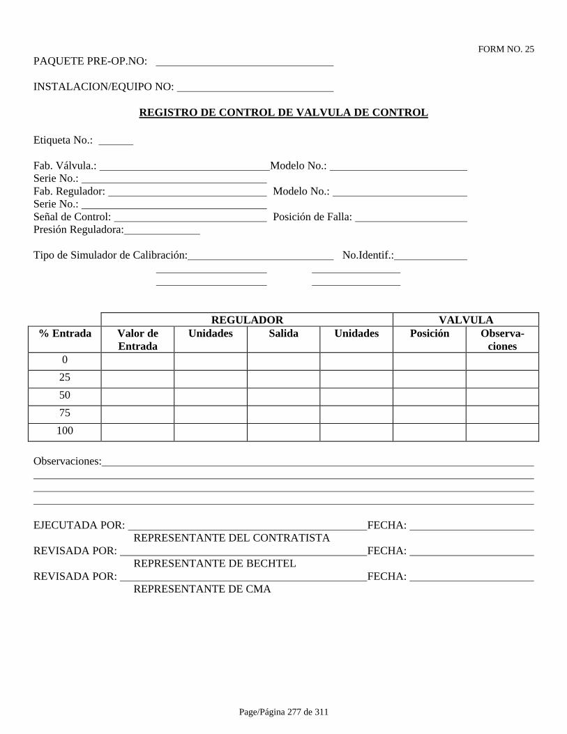
Page/Página 277 de 311
FORM NO. 25PAQUETE PRE-OP.NO:
INSTALACION/EQUIPO NO:
REGISTRO DE CONTROL DE VALVULA DE CONTROL
Etiqueta No.:
Fab. Válvula.: Modelo No.: Serie No.: Fab. Regulador: Modelo No.: Serie No.: Señal de Control: Posición de Falla: Presión Reguladora:
Tipo de Simulador de Calibración: No.Identif.:
REGULADOR VALVULA% Entrada Valor de
EntradaUnidades Salida Unidades Posición Observa-
ciones0
25
50
75
100
Observaciones:
EJECUTADA POR: FECHA: REPRESENTANTE DEL CONTRATISTA
REVISADA POR: FECHA: REPRESENTANTE DE BECHTEL
REVISADA POR: FECHA: REPRESENTANTE DE CMA
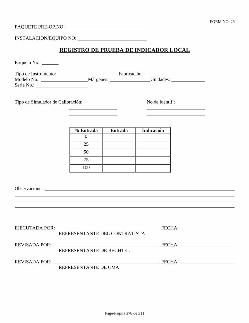
Page/Página 278 de 311
FORM NO. 26PAQUETE PRE-OP.NO:
INSTALACION/EQUIPO NO:
REGISTRO DE PRUEBA DE INDICADOR LOCAL
Etiqueta No.:
Tipo de Instrumento: Fabricación: Modelo No.: Márgenes: Unidades: Serie No.:
Tipo de Simulador de Calibración: No.de identif.:
% Entrada Entrada Indicación0
25
50
75
100
Observaciones:
EJECUTADA POR: FECHA: REPRESENTANTE DEL CONTRATISTA
REVISADA POR: FECHA: REPRESENTANTE DE BECHTEL
REVISADA POR: FECHA: REPRESENTANTE DE CMA
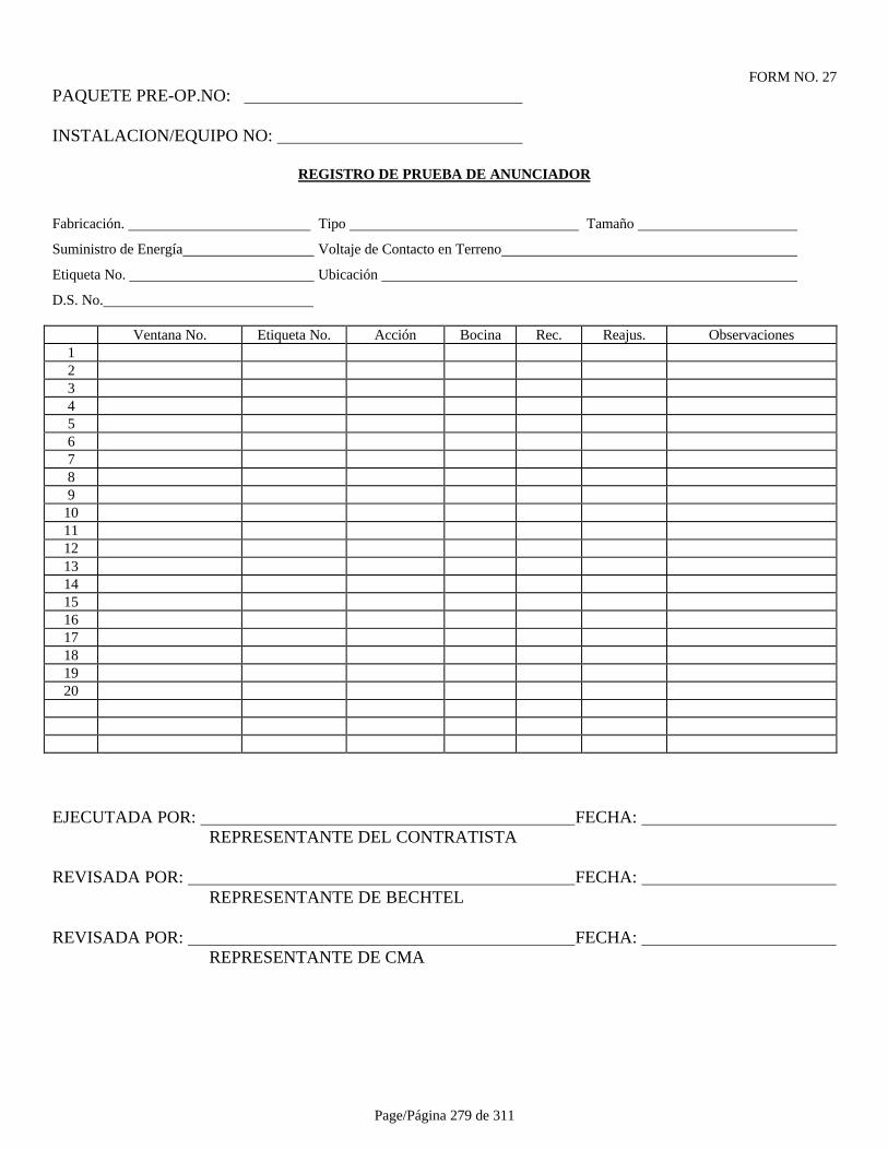
Page/Página 279 de 311
FORM NO. 27PAQUETE PRE-OP.NO:
INSTALACION/EQUIPO NO:
REGISTRO DE PRUEBA DE ANUNCIADOR
Fabricación. Tipo Tamaño
Suministro de Energía Voltaje de Contacto en Terreno
Etiqueta No. Ubicación
D.S. No.
Ventana No. Etiqueta No. Acción Bocina Rec. Reajus. Observaciones123456789
1011121314151617181920
EJECUTADA POR: FECHA: REPRESENTANTE DEL CONTRATISTA
REVISADA POR: FECHA: REPRESENTANTE DE BECHTEL
REVISADA POR: FECHA: REPRESENTANTE DE CMA
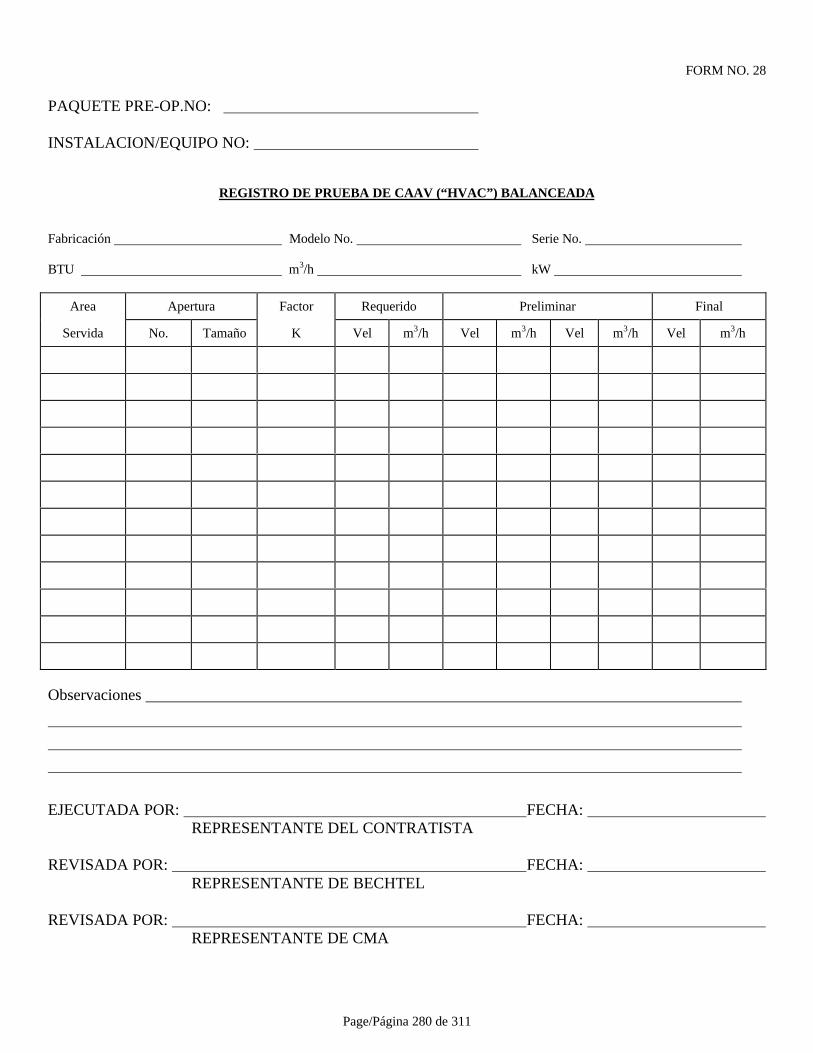
Page/Página 280 de 311
FORM NO. 28
PAQUETE PRE-OP.NO:
INSTALACION/EQUIPO NO:
REGISTRO DE PRUEBA DE CAAV (“HVAC”) BALANCEADA
Fabricación Modelo No. Serie No.
BTU m3/h kW
Area Apertura Factor Requerido Preliminar Final
Servida No. Tamaño K Vel m3/h Vel m3/h Vel m3/h Vel m3/h
Observaciones
EJECUTADA POR: FECHA: REPRESENTANTE DEL CONTRATISTA
REVISADA POR: FECHA: REPRESENTANTE DE BECHTEL
REVISADA POR: FECHA: REPRESENTANTE DE CMA
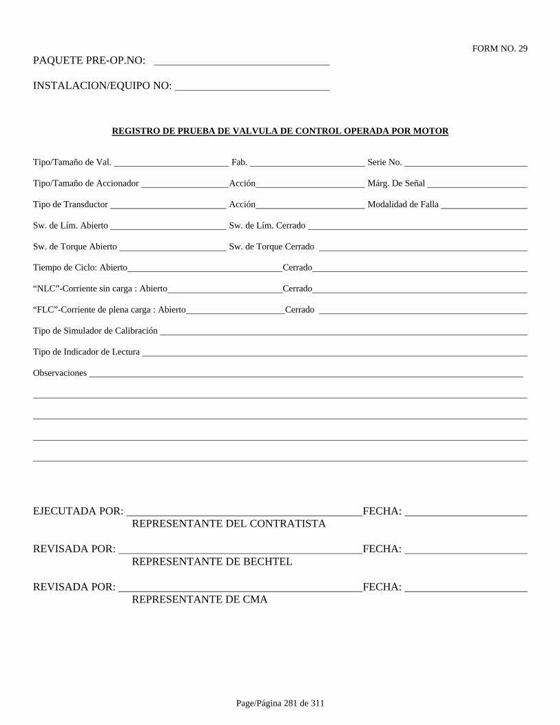
Page/Página 281 de 311
FORM NO. 29PAQUETE PRE-OP.NO:
INSTALACION/EQUIPO NO:
REGISTRO DE PRUEBA DE VALVULA DE CONTROL OPERADA POR MOTOR
Tipo/Tamaño de Val. Fab. Serie No.
Tipo/Tamaño de Accionador Acción Márg. De Señal
Tipo de Transductor Acción Modalidad de Falla
Sw. de Lím. Abierto Sw. de Lím. Cerrado
Sw. de Torque Abierto Sw. de Torque Cerrado
Tiempo de Ciclo: Abierto Cerrado
“NLC”-Corriente sin carga : Abierto Cerrado
“FLC”-Corriente de plena carga : Abierto Cerrado
Tipo de Simulador de Calibración
Tipo de Indicador de Lectura
Observaciones
EJECUTADA POR: FECHA: REPRESENTANTE DEL CONTRATISTA
REVISADA POR: FECHA: REPRESENTANTE DE BECHTEL
REVISADA POR: FECHA: REPRESENTANTE DE CMA
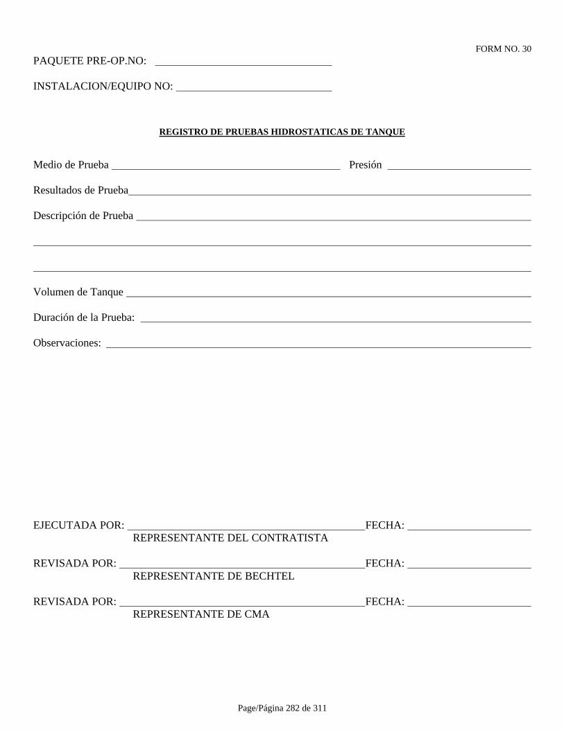
Page/Página 282 de 311
FORM NO. 30PAQUETE PRE-OP.NO:
INSTALACION/EQUIPO NO:
REGISTRO DE PRUEBAS HIDROSTATICAS DE TANQUE
Medio de Prueba Presión
Resultados de Prueba
Descripción de Prueba
Volumen de Tanque
Duración de la Prueba:
Observaciones:
EJECUTADA POR: FECHA: REPRESENTANTE DEL CONTRATISTA
REVISADA POR: FECHA: REPRESENTANTE DE BECHTEL
REVISADA POR: FECHA: REPRESENTANTE DE CMA

Page/Página 283 de 311
FORM NO. 31
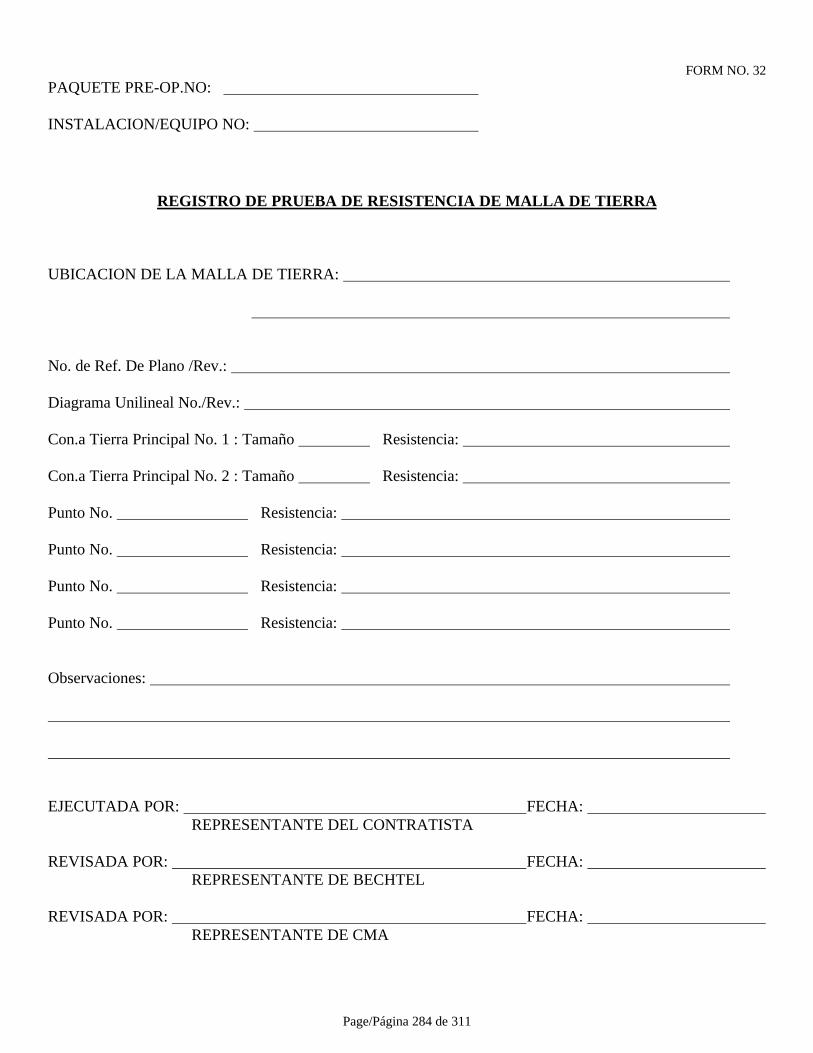
Page/Página 284 de 311
FORM NO. 32PAQUETE PRE-OP.NO:
INSTALACION/EQUIPO NO:
REGISTRO DE PRUEBA DE RESISTENCIA DE MALLA DE TIERRA
UBICACION DE LA MALLA DE TIERRA:
No. de Ref. De Plano /Rev.:
Diagrama Unilineal No./Rev.:
Con.a Tierra Principal No. 1 : Tamaño Resistencia:
Con.a Tierra Principal No. 2 : Tamaño Resistencia:
Punto No. Resistencia:
Punto No. Resistencia:
Punto No. Resistencia:
Punto No. Resistencia:
Observaciones:
EJECUTADA POR: FECHA: REPRESENTANTE DEL CONTRATISTA
REVISADA POR: FECHA: REPRESENTANTE DE BECHTEL
REVISADA POR: FECHA: REPRESENTANTE DE CMA

Page/Página 285 de 311
FORM NO. 33PAQUETE PRE-OP.NO:
INSTALACION/EQUIPO NO:
REGISTRO DE PRUEBA DE MOTOR
Diagrama Unilineal No./Rev: Esquema de Control No./Rev :
Fab.: kW: Volts: Amps: Estructura: Clasif.Aisl: Aumento °C: Factor Servicio: ___ Tarea: _________RPM: Rotación (Vista @ Extremo Desc.Ext.): Tipo Desc.: Diseño: ____________________ (Rotor Cerrado) Código o Corrientes: ___________________________CCM No.: Cubículo No.: Tamaño Arrancador: Clasif.Circuito: Fusible de Control: Voltaje Control: Tamaño Calentador Sobrecarga:
No.Identif. Megóhm.: Volts Megóhm.: Tiempo de Prueba:
RESISTENCIA DE AISL. A/T B/T C/T A/B B/C C/AMEGHOMS ANTES DE OP.
Rotación Manual: Drenaje Condens.: Estructura: Lubricación : Ventilación:
CORRIENTE POR FASE A B CAMPS SIN CARGA
AMPS CARGA PLENA
Temp.de Desc. (Interno): (Externo): Vibr.de Desc. (Interno): (Externo): Fuente Calefactor Anti-Condens.: Megohms Calefactor Anti-Condens: Amps CalefactorAnti-Condens:
Observaciones:
EJECUTADA POR: FECHA: REPRESENTANTE DEL CONTRATISTA
REVISADA POR: FECHA: REPRESENTANTE DE BECHTEL
REVISADA POR: FECHA: REPRESENTANTE DE CMA

Page/Página 286 de 311
FORM NO. 34
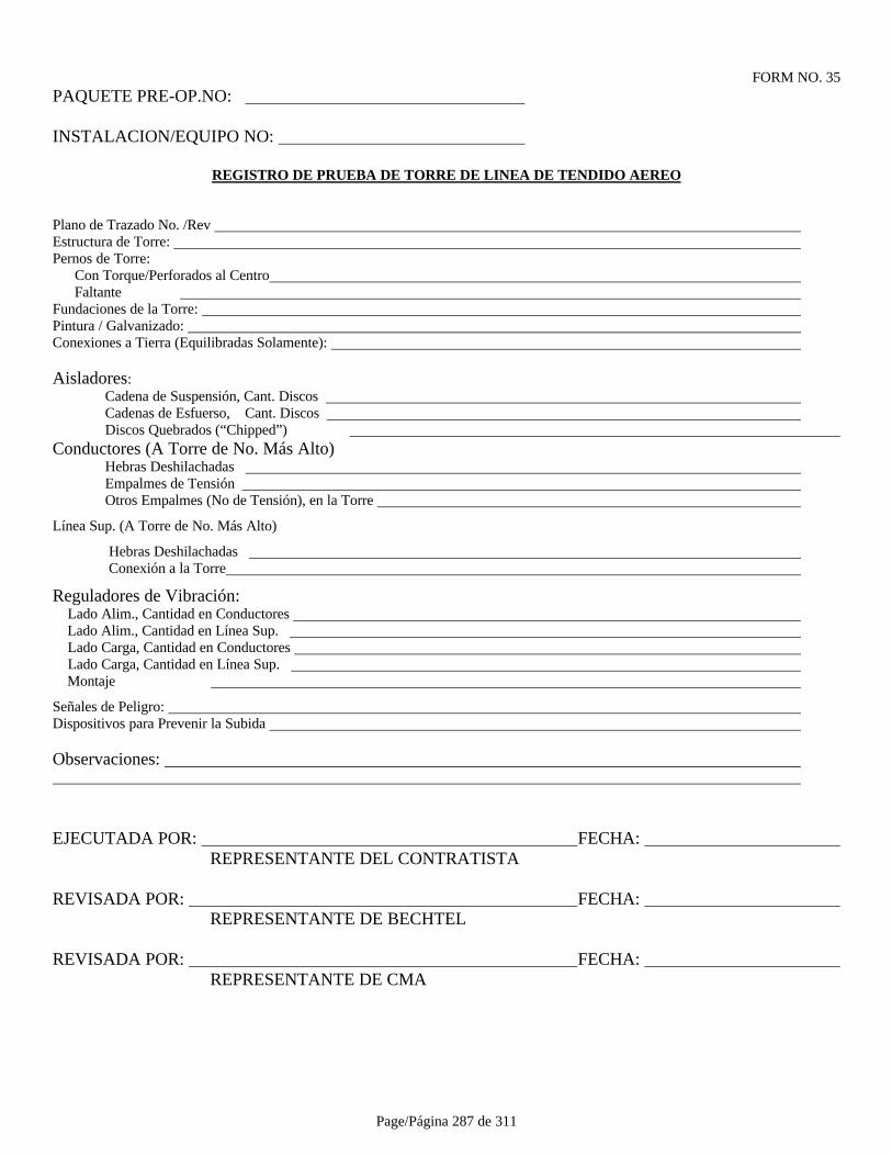
Page/Página 287 de 311
FORM NO. 35PAQUETE PRE-OP.NO:
INSTALACION/EQUIPO NO:
REGISTRO DE PRUEBA DE TORRE DE LINEA DE TENDIDO AEREO
Plano de Trazado No. /Rev Estructura de Torre: Pernos de Torre: Con Torque/Perforados al Centro Faltante Fundaciones de la Torre: Pintura / Galvanizado: Conexiones a Tierra (Equilibradas Solamente):
Aisladores:Cadena de Suspensión, Cant. Discos Cadenas de Esfuerso, Cant. Discos Discos Quebrados (“Chipped”)
Conductores (A Torre de No. Más Alto) Hebras Deshilachadas Empalmes de Tensión Otros Empalmes (No de Tensión), en la Torre
Línea Sup. (A Torre de No. Más Alto)
Hebras Deshilachadas Conexión a la Torre
Reguladores de Vibración: Lado Alim., Cantidad en Conductores Lado Alim., Cantidad en Línea Sup. Lado Carga, Cantidad en Conductores Lado Carga, Cantidad en Línea Sup. Montaje
Señales de Peligro: Dispositivos para Prevenir la Subida
Observaciones:
EJECUTADA POR: FECHA: REPRESENTANTE DEL CONTRATISTA
REVISADA POR: FECHA: REPRESENTANTE DE BECHTEL
REVISADA POR: FECHA: REPRESENTANTE DE CMA

Page/Página 288 de 311
FORM NO. 36PAQUETE PRE-OP.NO:
INSTALACION/EQUIPO NO:
REGISTRO DE PRUEBA DE TRANSFORMADOR DE CORRIENTE
Identif.de Interruptor.:
Fabric.:
Identif. de Transformador: Razón:
Esquema / Plano No.:
Test Equipment:
Verificación de Prueba de Inyección Razón ConexiónPolaridad Primaria Secundaria Medida Secundaria
Observaciones:
EJECUTADA POR: FECHA: REPRESENTANTE DEL CONTRATISTA
REVISADA POR: FECHA: REPRESENTANTE DE BECHTEL
REVISADA POR: FECHA: REPRESENTANTE DE CMA

Page/Página 289 de 311
FORM NO. 37PAQUETE PRE-OP.NO:
INSTALACION/EQUIPO NO:
REGISTRO DE PRUEBA DE VOLTIMETRO Y AMPERIMETRO
Identif.de Interruptor:
Esquema/Plano No.:
Razón de Trans.Corr/Pot: Alcance de Medida: Unidades Identif.de Estándar de Calibración:
% Escala Estándar Medición0
255075100
Observaciones:
EJECUTADA POR: FECHA: REPRESENTANTE DEL CONTRATISTA
REVISADA POR: FECHA: REPRESENTANTE DE BECHTEL
REVISADA POR: FECHA: REPRESENTANTE DE CMA

Page/Página 290 de 311
FORM NO. 38-1PRE-OP PACKAGE NO.:
FACILITY EQUIPMENT NO.:
REGISTRO DE PRUEBA DE INTERRUPTOR DE CIRCUITO DE MEDIO VOLTAJE
DATOS DE INTERRUPTOR DE CIRCUITO
Fabricante:
Tipo de Interruptor de Ciruito: Estilo: No. de Serie.:
CARACTERISTICAS ELECTRICAS
Corriente Continua: amp Voltaje de Sistema: Clasificación de Interr.: mVA Voltaje de Cierre de Bobina: Voltaje de Clasif.: Voltaje de Disparo de Bobina:
INSPECCION
CondiciónPunto de Control Aceptado Reparable Rechazado Observaciones
Carro Extraíble
Contactos Primarios
Contactos Secundarios
Contactos Principales
Contactos de Arco
Pantallas Protectoras de Arco
Secuencia de Contacto
Presión de Contactor
Conjunto de Cámara de Extinción tipo“Puffer”
Resorte de Carga
Mecanismo de Sujeción
Mecanismo de Disparo
Dispositivos de Enclavamiento
Limpieza
Apriete de Ferretería
Condición de Celda
Alineamiento de Interr.en Celda
Equipo de Mantenimiento
Interruptor de Control/Luces Indic.
Operaciones de Contrapeso
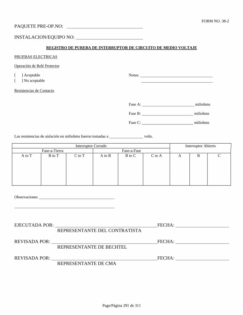
Page/Página 291 de 311
FORM NO. 38-2PAQUETE PRE-OP.NO:
INSTALACION/EQUIPO NO:
REGISTRO DE PUREBA DE INTERRUPTOR DE CIRCUITO DE MEDIO VOLTAJE
PRUEBAS ELECTRICAS
Operación de Relé Protector
[ ] Aceptable Notas: [ ] No aceptable
Resistencias de Contacto
Fase A: miliohms
Fase B: miliohms
Fase C: miliohms
Las resistencias de aislación en miliohms fueron tomadas a volts.
Interruptor Cerrado Interruptor AbiertoFase-a-Tierra Fase-a-Fase
A to T B to T C to T A to B B to C C to A A B C
Observaciones
EJECUTADA POR: FECHA: REPRESENTANTE DEL CONTRATISTA
REVISADA POR: FECHA: REPRESENTANTE DE BECHTEL
REVISADA POR: FECHA: REPRESENTANTE DE CMA
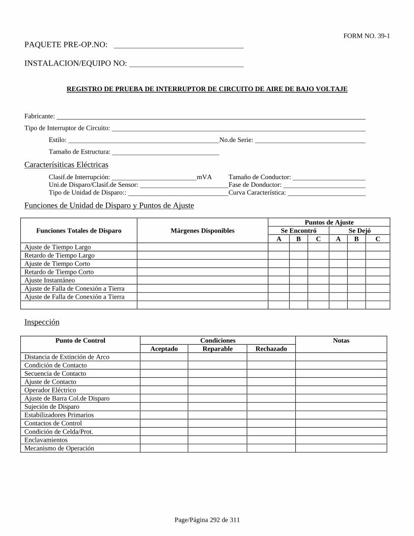
Page/Página 292 de 311
FORM NO. 39-1PAQUETE PRE-OP.NO:
INSTALACION/EQUIPO NO:
REGISTRO DE PRUEBA DE INTERRUPTOR DE CIRCUITO DE AIRE DE BAJO VOLTAJE
Fabricante:
Tipo de Interruptor de Circuito:
Estilo: No.de Serie:
Tamaño de Estructura:
Caracterísiticas Eléctricas
Clasif.de Interrupción: mVA Tamaño de Conductor: Uni.de Disparo/Clasif.de Sensor: Fase de Donductor: Tipo de Unidad de Disparo:: Curva Característica:
Funciones de Unidad de Disparo y Puntos de Ajuste
Puntos de AjusteFunciones Totales de Disparo Márgenes Disponibles Se Encontró Se Dejó
A B C A B CAjuste de Tiempo LargoRetardo de Tiempo LargoAjuste de Tiempo CortoRetardo de Tiempo CortoAjuste InstantáneoAjuste de Falla de Conexión a TierraAjuste de Falla de Conexión a Tierra
Inspección
Punto de Control Condiciones NotasAceptado Reparable Rechazado
Distancia de Extinción de ArcoCondición de ContactoSecuencia de ContactoAjuste de ContactoOperador EléctricoAjuste de Barra Col.de DisparoSujeción de DisparoEstabilizadores PrimariosContactos de ControlCondición de Celda/Prot.EnclavamientosMecanismo de Operación
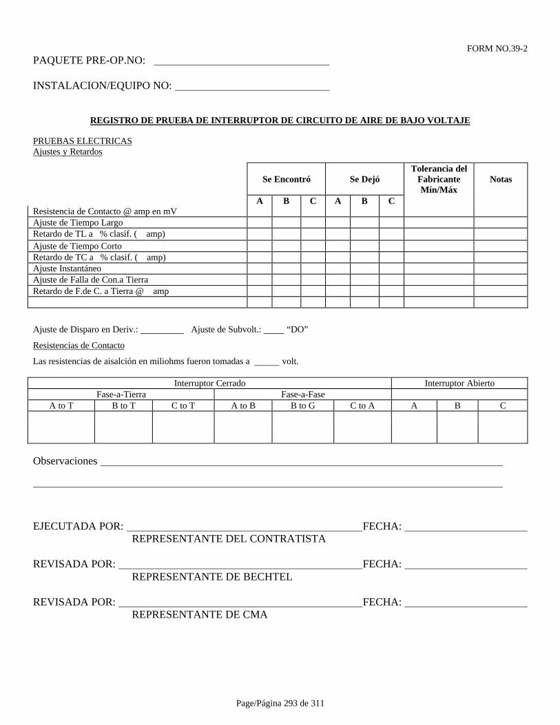
Page/Página 293 de 311
FORM NO.39-2PAQUETE PRE-OP.NO:
INSTALACION/EQUIPO NO:
REGISTRO DE PRUEBA DE INTERRUPTOR DE CIRCUITO DE AIRE DE BAJO VOLTAJE
PRUEBAS ELECTRICASAjustes y Retardos
Se Encontró Se DejóTolerancia del
FabricanteMín/Máx
Notas
A B C A B CResistencia de Contacto @ amp en mVAjuste de Tiempo LargoRetardo de TL a % clasif. ( amp)Ajuste de Tiempo CortoRetardo de TC a % clasif. ( amp)Ajuste InstantáneoAjuste de Falla de Con.a TierraRetardo de F.de C. a Tierra @ amp
Ajuste de Disparo en Deriv.: Ajuste de Subvolt.: “DO”
Resistencias de Contacto
Las resistencias de aisalción en miliohms fueron tomadas a volt.
Interruptor Cerrado Interruptor AbiertoFase-a-Tierra Fase-a-Fase
A to T B to T C to T A to B B to G C to A A B C
Observaciones
EJECUTADA POR: FECHA: REPRESENTANTE DEL CONTRATISTA
REVISADA POR: FECHA: REPRESENTANTE DE BECHTEL
REVISADA POR: FECHA: REPRESENTANTE DE CMA
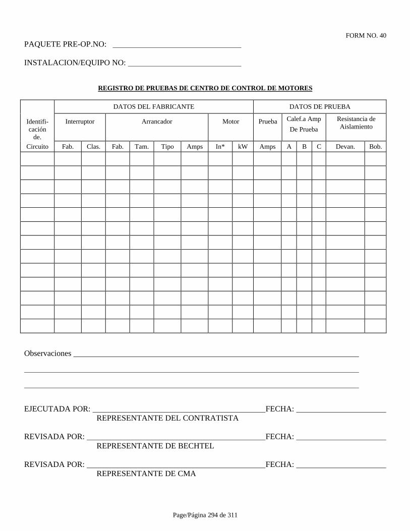
Page/Página 294 de 311
FORM NO. 40PAQUETE PRE-OP.NO:
INSTALACION/EQUIPO NO:
REGISTRO DE PRUEBAS DE CENTRO DE CONTROL DE MOTORES
DATOS DEL FABRICANTE DATOS DE PRUEBA
Identifi-cación
de.
Interruptor Arrancador Motor Prueba Calef.a Amp
De Prueba
Resistancia deAislamiento
Circuito Fab. Clas. Fab. Tam. Tipo Amps In* kW Amps A B C Devan. Bob.
Observaciones
EJECUTADA POR: FECHA: REPRESENTANTE DEL CONTRATISTA
REVISADA POR: FECHA: REPRESENTANTE DE BECHTEL
REVISADA POR: FECHA: REPRESENTANTE DE CMA
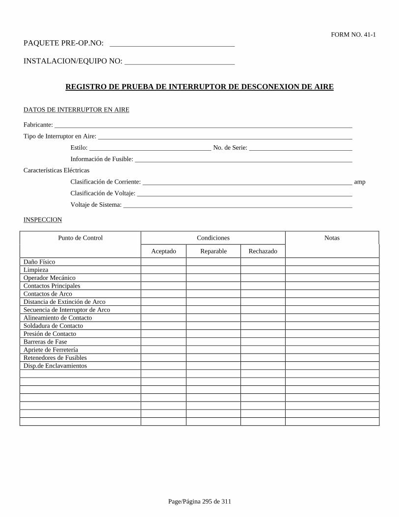
Page/Página 295 de 311
FORM NO. 41-1PAQUETE PRE-OP.NO:
INSTALACION/EQUIPO NO:
REGISTRO DE PRUEBA DE INTERRUPTOR DE DESCONEXION DE AIRE
DATOS DE INTERRUPTOR EN AIRE
Fabricante:
Tipo de Interruptor en Aire:
Estilo: No. de Serie:
Información de Fusible:
Características Eléctricas
Clasificación de Corriente: amp
Clasificación de Voltaje:
Voltaje de Sistema:
INSPECCION
Punto de Control Condiciones Notas
Aceptado Reparable Rechazado
Daño FísicoLimpiezaOperador MecánicoContactos PrincipalesContactos de ArcoDistancia de Extinción de ArcoSecuencia de Interruptor de ArcoAlineamiento de ContactoSoldadura de ContactoPresión de ContactoBarreras de FaseApriete de FerreteríaRetenedores de FusiblesDisp.de Enclavamientos
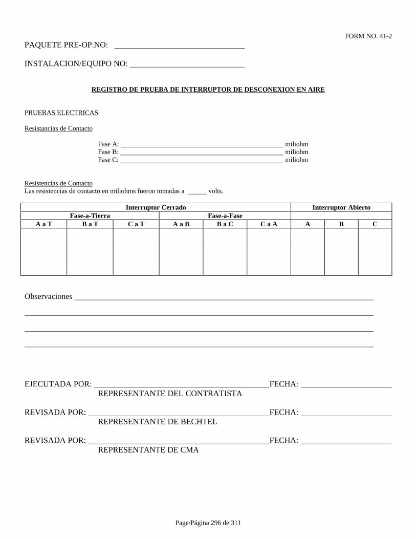
Page/Página 296 de 311
FORM NO. 41-2PAQUETE PRE-OP.NO:
INSTALACION/EQUIPO NO:
REGISTRO DE PRUEBA DE INTERRUPTOR DE DESCONEXION EN AIRE
PRUEBAS ELECTRICAS
Resistancias de Contacto
Fase A: miliohmFase B: miliohmFase C: miliohm
Resistencias de ContactoLas resistencias de contacto en miliohms fueron tomadas a volts.
Interruptor Cerrado Interruptor AbiertoFase-a-Tierra Fase-a-Fase
A a T B a T C a T A a B B a C C a A A B C
Observaciones
EJECUTADA POR: FECHA: REPRESENTANTE DEL CONTRATISTA
REVISADA POR: FECHA: REPRESENTANTE DE BECHTEL
REVISADA POR: FECHA: REPRESENTANTE DE CMA

Page/Página 297 de 311
FORM NO. 42-1PAQUETE PRE-OP.NO:
INSTALACION/EQUIPO NO:
REGISTRO DE PRUEBAS DE MOTOR SINCRONICO
Fabricación HP Factor de Servicio
Factor de Potencia
Estator (V) (A) Tamaño de Cable
Tipo de Excitación: Escobilla Sin Escobilla
Estructura Clase de Aislación Aumento de Temp. °C ____________
RPM Rotación Bi-Direccional
Si no, Rotación frente a Extremo Accionado Tipo de Desc.
Método de Arranque: Arrancador Interruptor de Circuito
Diagrama Unilineal No./Rev.
Esq.Control de Arrancador No./Rev. Hoja de Datos Motor No./Rev.
Esq.Control Excitador No./Rev. Curva V No./Rev.
PRUEBAS PREOPERACIONALES
A) ANILLOS DESL. Y ESCOBILLAS: (SI CORRESPONDE)
Condición Anillo Deslizante Calidad de Escobilla
Alineamiento de Escobilla Asentamiento de Escobilla
Libertad de Escobilla Tensión de Resortes
B) PRUEBAS DE AISLACION
Clasif. De Megóhmetro Volts
Resistencia de Aisl.en Megohms Estator Rotor RTD's
Pedestal de Desc.Delant./Tras.
PruebaDe Fáb.
PruebaEn Faena
PruebaDe Fáb.
PruebaEn Faena
PruebaDe Fáb.
PruebaEn Faena
PruebaDe Fáb.
PruebaEn Faena
Antes de OperarDespués de Op. Inicial
* PRECAUCION: No aplicar pruebas de Megóhmetro a dispositivos de estado sólido conectados a devanaciones de rotor.
Se requiere secado en devanaciones Amarra de tierra de pedestal de descansofue recambiada luego del control de aislación
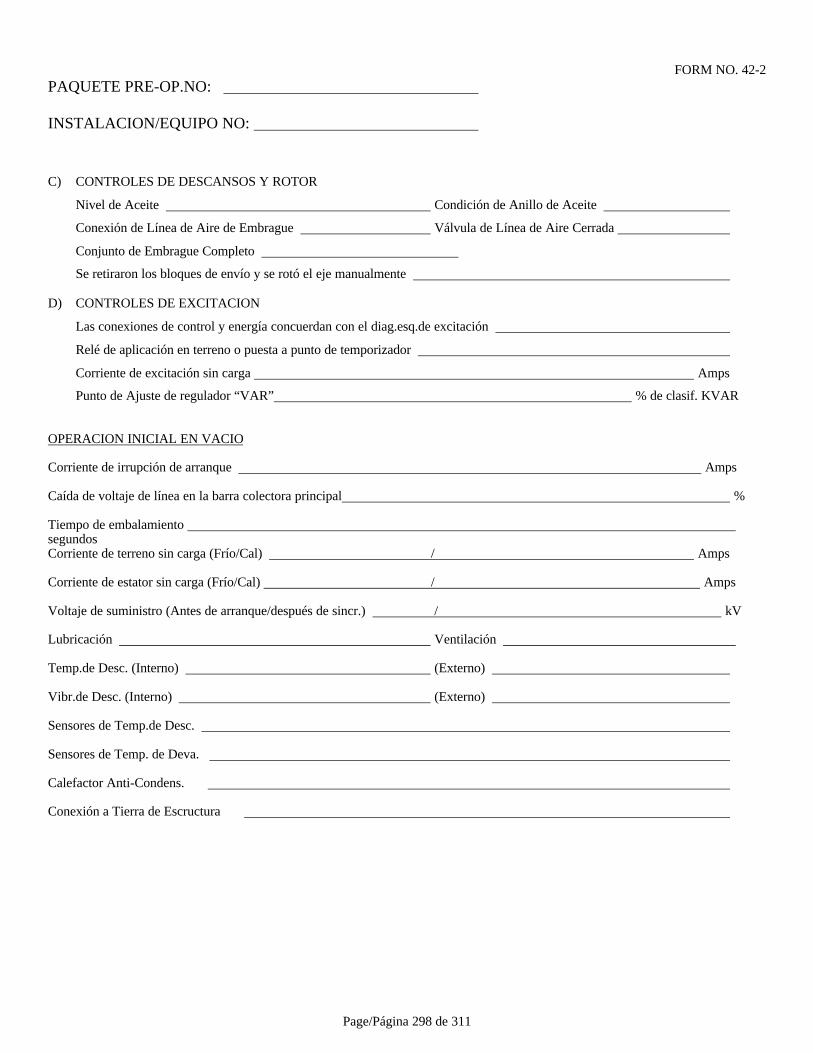
Page/Página 298 de 311
FORM NO. 42-2PAQUETE PRE-OP.NO:
INSTALACION/EQUIPO NO:
C) CONTROLES DE DESCANSOS Y ROTOR
Nivel de Aceite Condición de Anillo de Aceite
Conexión de Línea de Aire de Embrague Válvula de Línea de Aire Cerrada
Conjunto de Embrague Completo
Se retiraron los bloques de envío y se rotó el eje manualmente
D) CONTROLES DE EXCITACION
Las conexiones de control y energía concuerdan con el diag.esq.de excitación
Relé de aplicación en terreno o puesta a punto de temporizador
Corriente de excitación sin carga Amps
Punto de Ajuste de regulador “VAR” % de clasif. KVAR
OPERACION INICIAL EN VACIO
Corriente de irrupción de arranque Amps
Caída de voltaje de línea en la barra colectora principal %
Tiempo de embalamiento segundosCorriente de terreno sin carga (Frío/Cal) / Amps
Corriente de estator sin carga (Frío/Cal) / Amps
Voltaje de suministro (Antes de arranque/después de sincr.) / kV
Lubricación Ventilación
Temp.de Desc. (Interno) (Externo)
Vibr.de Desc. (Interno) (Externo)
Sensores de Temp.de Desc.
Sensores de Temp. de Deva.
Calefactor Anti-Condens.
Conexión a Tierra de Escructura
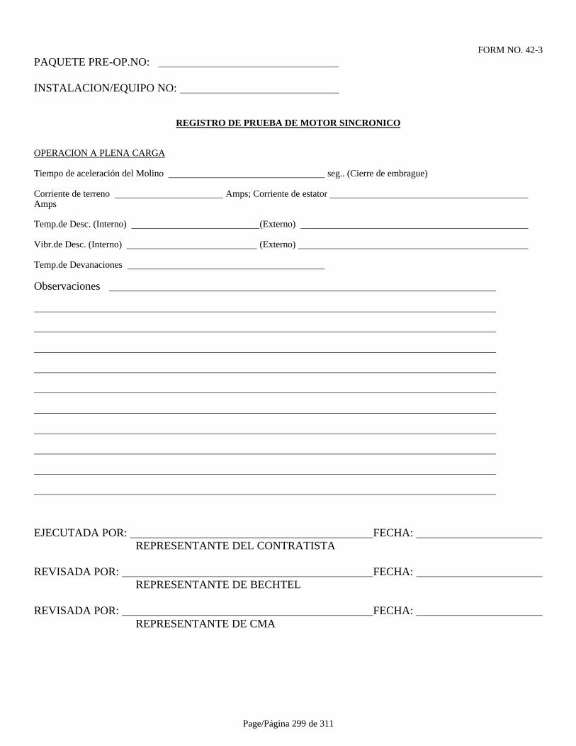
Page/Página 299 de 311
FORM NO. 42-3PAQUETE PRE-OP.NO:
INSTALACION/EQUIPO NO:
REGISTRO DE PRUEBA DE MOTOR SINCRONICO
OPERACION A PLENA CARGA
Tiempo de aceleración del Molino seg.. (Cierre de embrague)
Corriente de terreno Amps; Corriente de estator Amps
Temp.de Desc. (Interno) (Externo)
Vibr.de Desc. (Interno) (Externo)
Temp.de Devanaciones
Observaciones
EJECUTADA POR: FECHA: REPRESENTANTE DEL CONTRATISTA
REVISADA POR: FECHA: REPRESENTANTE DE BECHTEL
REVISADA POR: FECHA: REPRESENTANTE DE CMA
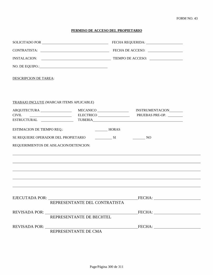
Page/Página 300 de 311
FORM NO. 43
PERMISO DE ACCESO DEL PROPIETARIO
SOLICITADO POR FECHA REQUERIDA:
CONTRATISTA: FECHA DE ACCESO:
INSTALACION: TIEMPO DE ACCESO:
NO. DE EQUIPO.:
DESCRIPCION DE TAREA:
TRABAJO INCLUYE (MARCAR ITEMS APLICABLE)
ARQUITECTURA MECANICO INSTRUMENTACION CIVIL ELECTRICO PRUEBAS PRE-OP. ESTRUCTURAL TUBERIA
ESTIMACION DE TIEMPO REQ.: HORAS
SE REQUIERE OPERADOR DEL PROPIETARIO SI NO
REQUERIMIENTOS DE AISLACION/DETENCION:
EJECUTADA POR: FECHA: REPRESENTANTE DEL CONTRATISTA
REVISADA POR: FECHA: REPRESENTANTE DE BECHTEL
REVISADA POR: FECHA: REPRESENTANTE DE CMA
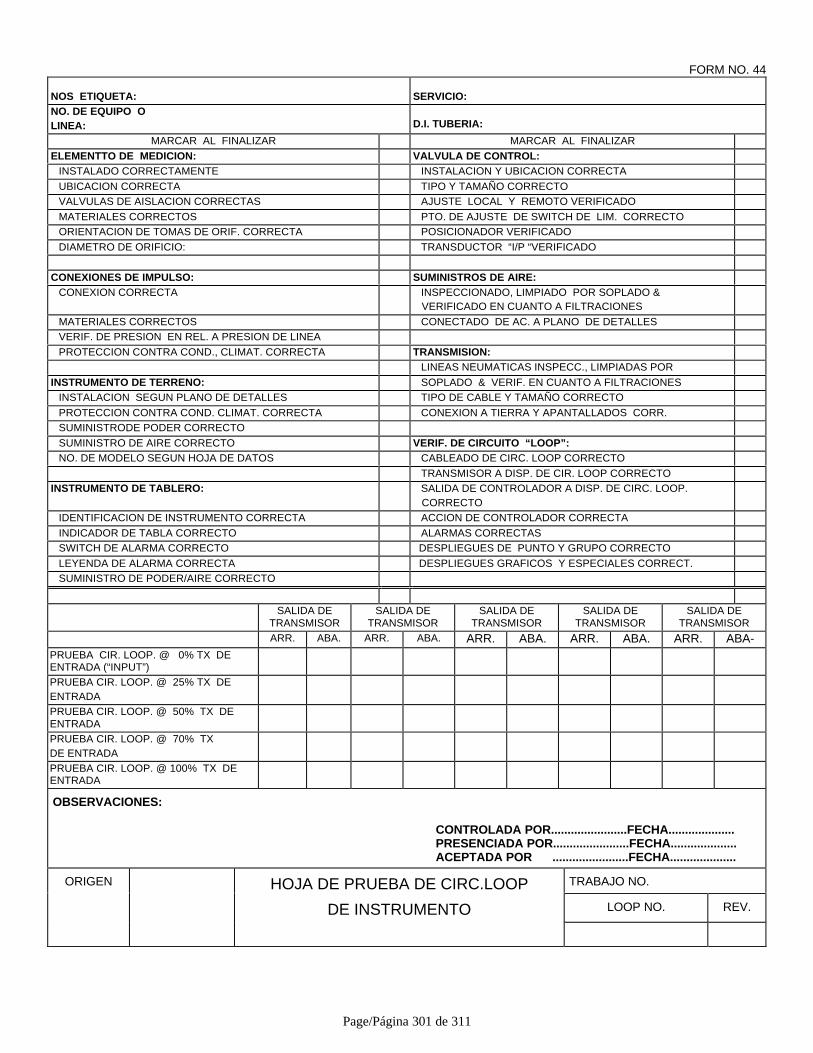
Page/Página 301 de 311
FORM NO. 44
NOS ETIQUETA: SERVICIO:NO. DE EQUIPO OLINEA: D.I. TUBERIA:
MARCAR AL FINALIZAR MARCAR AL FINALIZAR
ELEMENTTO DE MEDICION: VALVULA DE CONTROL:INSTALADO CORRECTAMENTE INSTALACION Y UBICACION CORRECTA
UBICACION CORRECTA TIPO Y TAMAÑO CORRECTOVALVULAS DE AISLACION CORRECTAS AJUSTE LOCAL Y REMOTO VERIFICADO
MATERIALES CORRECTOS PTO. DE AJUSTE DE SWITCH DE LIM. CORRECTOORIENTACION DE TOMAS DE ORIF. CORRECTA POSICIONADOR VERIFICADO
DIAMETRO DE ORIFICIO: TRANSDUCTOR “I/P “VERIFICADO
CONEXIONES DE IMPULSO: SUMINISTROS DE AIRE:CONEXION CORRECTA INSPECCIONADO, LIMPIADO POR SOPLADO &
VERIFICADO EN CUANTO A FILTRACIONES
MATERIALES CORRECTOS CONECTADO DE AC. A PLANO DE DETALLESVERIF. DE PRESION EN REL. A PRESION DE LINEA
PROTECCION CONTRA COND., CLIMAT. CORRECTA TRANSMISION:LINEAS NEUMATICAS INSPECC., LIMPIADAS POR
INSTRUMENTO DE TERRENO: SOPLADO & VERIF. EN CUANTO A FILTRACIONESINSTALACION SEGUN PLANO DE DETALLES TIPO DE CABLE Y TAMAÑO CORRECTO
PROTECCION CONTRA COND. CLIMAT. CORRECTA CONEXION A TIERRA Y APANTALLADOS CORR.SUMINISTRODE PODER CORRECTO
SUMINISTRO DE AIRE CORRECTO VERIF. DE CIRCUITO “LOOP”:NO. DE MODELO SEGUN HOJA DE DATOS CABLEADO DE CIRC. LOOP CORRECTO
TRANSMISOR A DISP. DE CIR. LOOP CORRECTOINSTRUMENTO DE TABLERO: SALIDA DE CONTROLADOR A DISP. DE CIRC. LOOP.
CORRECTOIDENTIFICACION DE INSTRUMENTO CORRECTA ACCION DE CONTROLADOR CORRECTA
INDICADOR DE TABLA CORRECTO ALARMAS CORRECTASSWITCH DE ALARMA CORRECTO DESPLIEGUES DE PUNTO Y GRUPO CORRECTO
LEYENDA DE ALARMA CORRECTA DESPLIEGUES GRAFICOS Y ESPECIALES CORRECT.SUMINISTRO DE PODER/AIRE CORRECTO
SALIDA DETRANSMISOR
SALIDA DETRANSMISOR
SALIDA DETRANSMISOR
SALIDA DETRANSMISOR
SALIDA DETRANSMISOR
ARR. ABA. ARR. ABA. ARR. ABA. ARR. ABA. ARR. ABA-PRUEBA CIR. LOOP. @ 0% TX DEENTRADA (“INPUT”)PRUEBA CIR. LOOP. @ 25% TX DEENTRADAPRUEBA CIR. LOOP. @ 50% TX DEENTRADAPRUEBA CIR. LOOP. @ 70% TXDE ENTRADAPRUEBA CIR. LOOP. @ 100% TX DEENTRADA
OBSERVACIONES:
CONTROLADA POR.......................FECHA....................PRESENCIADA POR.......................FECHA....................ACEPTADA POR .......................FECHA....................
ORIGEN HOJA DE PRUEBA DE CIRC.LOOP TRABAJO NO.
DE INSTRUMENTO LOOP NO. REV.
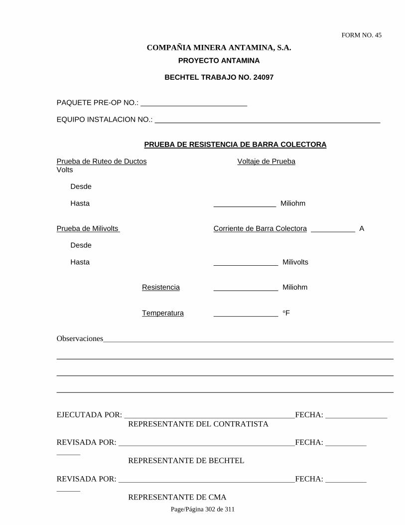
Page/Página 302 de 311
FORM NO. 45
COMPAÑIA MINERA ANTAMINA, S.A.
PROYECTO ANTAMINA
BECHTEL TRABAJO NO. 24097
PAQUETE PRE-OP NO.:
EQUIPO INSTALACION NO.:
PRUEBA DE RESISTENCIA DE BARRA COLECTORA
Prueba de Ruteo de Ductos Voltaje de Prueba Volts
Desde
Hasta Miliohm
Prueba de Milivolts Corriente de Barra Colectora A
Desde
Hasta Milivolts
Resistencia Miliohm
Temperatura °F
Observaciones
EJECUTADA POR: FECHA: REPRESENTANTE DEL CONTRATISTA
REVISADA POR: FECHA:
REPRESENTANTE DE BECHTEL
REVISADA POR: FECHA:
REPRESENTANTE DE CMA

Page/Página 303 de 311
FORM NO. 46PAQUETE PRE-OP.NO:
INSTALACION/EQUIPO NO:
REGISTRO DE PRUEBA DE RIGIDEZ DIELECTRICA DE ACEITE PARA TRANSFORMADORES
Equipo No.: ______________________________________________________________________Descripción: _________________________________________________________________________
Fab.: Tipo: Clasificación: HV: LV Hz Serie No.: Enfriamiento: Referencia Plano/ Diag. Unilineal: ______
Prueba No. 1: Prueba No. 2:
Prueba No. 3: Prueba No. 4:
Prueba No. 5: Prueba No. 5:
Promedio: Mínimo:
Observaciones:
EJECUTADA POR: FECHA: REPRESENTANTE DEL CONTRATISTA
REVISADA POR: FECHA: REPRESENTANTE DE BECHTEL
REVISADA POR: FECHA: REPRESENTANTE DE CMA

Page/Página 304 de 311
FORM NO. 47PAQUETE PRE-OP.NO:
INSTALACION/EQUIPO NO:
REGISTRO DE PRUEBA DE DISTRIBUCION ELECTRICA
Equipo No.: Descripción: Fabricante:
Plano Diag. Unilineal. No.: _______________________
Interruptor Primario: Clasificación de Interruptor: Ajuste de Disparo:
Pruebas de Aislación:Prueba Ajuste: _____________________ Prueba Volts: __________________ Duración: _________________
Aisl.Principal y Cable F. A a Tierra F. B a Tierra F. C a Tierra
F. A a F. B F. B a F. C F. C a F. A
Barra ColectoraPrincipal
F. A a Tierra F. B a Tierra F. C a Tierra
F. A a F. B F. B a F. C F. C a F. A
Prueba energizada:Main BusVoltage F. A a F. B F. B a F. C F. C a F. A
Fuente alta tensión anti-condens.: Megohms alta tensión anti-condens.: Amps alta tensiónanti-condens.:
Observaciones ____________________________________________________________________________________
EJECUTADA POR: FECHA: REPRESENTANTE DEL CONTRATISTA
REVISADA POR: FECHA: REPRESENTANTE DE BECHTEL
REVISADA POR: FECHA: REPRESENTANTE DE CMA
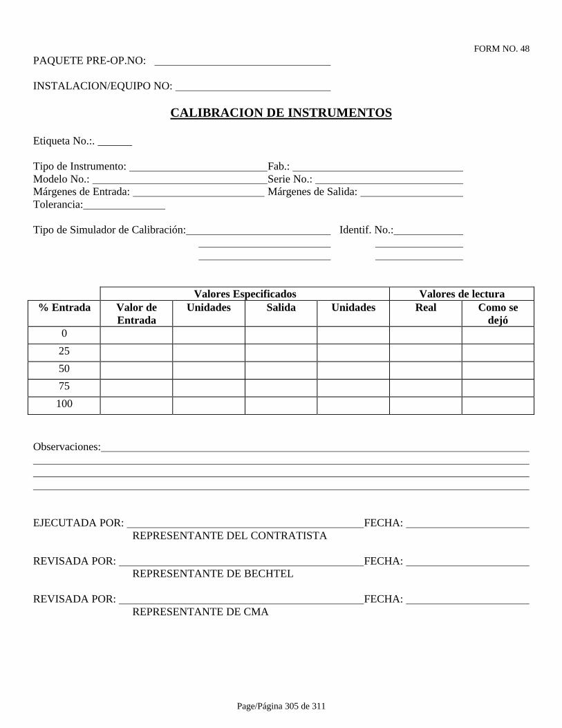
Page/Página 305 de 311
FORM NO. 48PAQUETE PRE-OP.NO:
INSTALACION/EQUIPO NO:
CALIBRACION DE INSTRUMENTOS
Etiqueta No.:.
Tipo de Instrumento: Fab.: Modelo No.: Serie No.: Márgenes de Entrada: Márgenes de Salida: Tolerancia:
Tipo de Simulador de Calibración: Identif. No.:
Valores Especificados Valores de lectura% Entrada Valor de
EntradaUnidades Salida Unidades Real Como se
dejó0
25
50
75
100
Observaciones:
EJECUTADA POR: FECHA: REPRESENTANTE DEL CONTRATISTA
REVISADA POR: FECHA: REPRESENTANTE DE BECHTEL
REVISADA POR: FECHA: REPRESENTANTE DE CMA
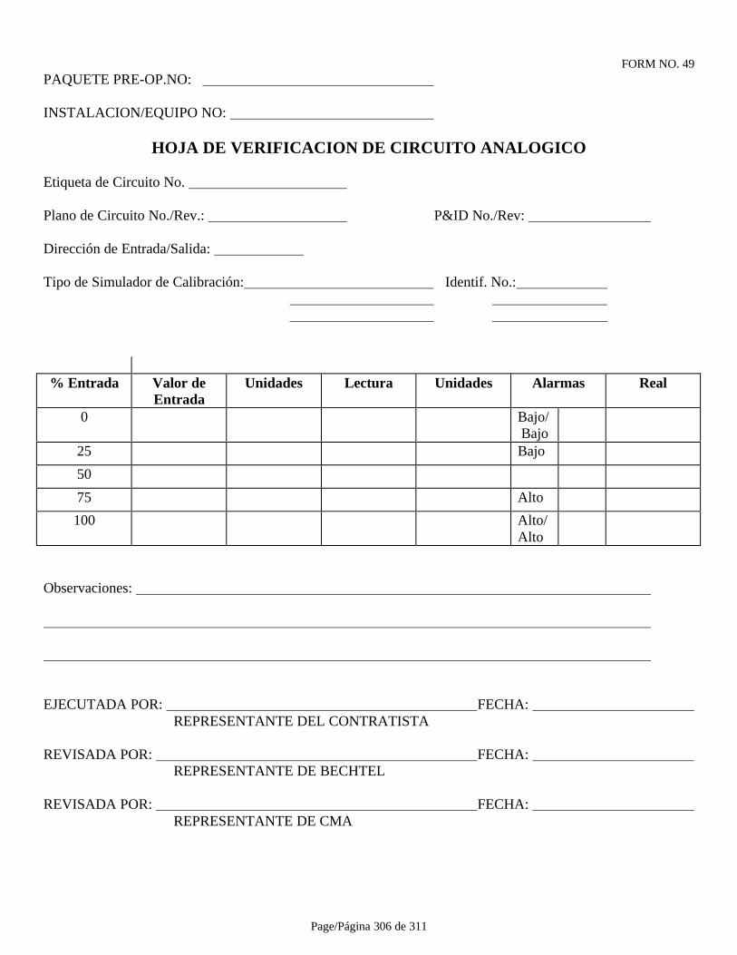
Page/Página 306 de 311
FORM NO. 49PAQUETE PRE-OP.NO:
INSTALACION/EQUIPO NO:
HOJA DE VERIFICACION DE CIRCUITO ANALOGICO
Etiqueta de Circuito No.
Plano de Circuito No./Rev.: P&ID No./Rev:
Dirección de Entrada/Salida:
Tipo de Simulador de Calibración: Identif. No.:
% Entrada Valor deEntrada
Unidades Lectura Unidades Alarmas Real
0 Bajo/Bajo
25 Bajo
50
75 Alto
100 Alto/Alto
Observaciones:
EJECUTADA POR: FECHA: REPRESENTANTE DEL CONTRATISTA
REVISADA POR: FECHA: REPRESENTANTE DE BECHTEL
REVISADA POR: FECHA: REPRESENTANTE DE CMA

Page/Página 307 de 311
FORM NO. 50PAQUETE PRE-OP.NO:
INSTALACION/EQUIPO NO:
REGISTRO DE PRUEBA DE CAAV BALANCEADA (HVAC)
Fab.: Modelo No.: No. de Serie.:
BTU: CFM: KW:
Area Apertura Factor Requerido Preliminar FinalServida No. Tamaño K Vel CFM Vel CFM Vel CFM Vel CFM
Observaciones:
EJECUTADA POR: FECHA: REPRESENTANTE DEL CONTRATISTA
REVISADA POR: FECHA: REPRESENTANTE DE BECHTEL
REVISADA POR: FECHA: REPRESENTANTE DE CMA

Page/Página 308 de 311
FORM NO. 51PAQUETE PRE-OP.NO:
INSTALACION/EQUIPO NO:
REGISTRO DE PRUEBA ADICIONAL DE CIRCUITO
Tipo: Fab.: Modelo No.:
Función:
P&ID No.: SLD No.:
Circuito No.: Esquema No.:
Prueba :
Equipo de Prueba:
Resultados:
Observaciones:
EJECUTADA POR: FECHA: REPRESENTANTE DEL CONTRATISTA
REVISADA POR: FECHA: REPRESENTANTE DE BECHTEL
REVISADA POR: FECHA: REPRESENTANTE DE CMA
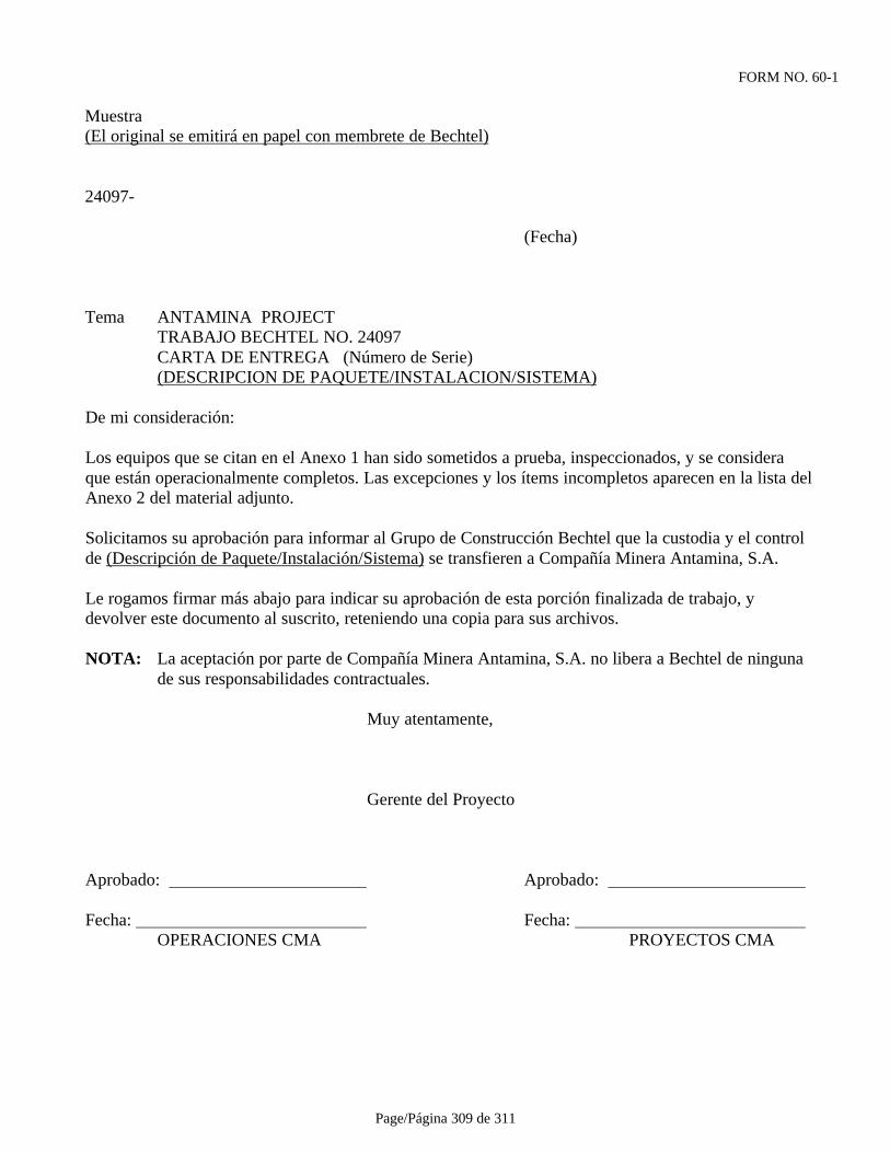
Page/Página 309 de 311
FORM NO. 60-1
Muestra(El original se emitirá en papel con membrete de Bechtel)
24097-
(Fecha)
Tema ANTAMINA PROJECTTRABAJO BECHTEL NO. 24097CARTA DE ENTREGA (Número de Serie)(DESCRIPCION DE PAQUETE/INSTALACION/SISTEMA)
De mi consideración:
Los equipos que se citan en el Anexo 1 han sido sometidos a prueba, inspeccionados, y se consideraque están operacionalmente completos. Las excepciones y los ítems incompletos aparecen en la lista delAnexo 2 del material adjunto.
Solicitamos su aprobación para informar al Grupo de Construcción Bechtel que la custodia y el controlde (Descripción de Paquete/Instalación/Sistema) se transfieren a Compañía Minera Antamina, S.A.
Le rogamos firmar más abajo para indicar su aprobación de esta porción finalizada de trabajo, ydevolver este documento al suscrito, reteniendo una copia para sus archivos.
NOTA: La aceptación por parte de Compañía Minera Antamina, S.A. no libera a Bechtel de ningunade sus responsabilidades contractuales.
Muy atentamente,
Gerente del Proyecto
Aprobado: Aprobado:
Fecha: Fecha: OPERACIONES CMA PROYECTOS CMA
Page/Página 310 de 311
FORM NO. 60-2Muestra(El original se emitirá en papel blanco de primera calidad)
Tema: PROYECTO ANTAMINA TRABAJO BECHTEL NO. 24097 CARTA DE ENTREGA (Número de Serie) (DESCRIPCION DE PAQUETE/INSTALACION/SISTEMA)
ANEXO I
Equipo Completo Operable
Item Descripción
(1) (No. de Equipo y Descripción)

Page/Página 311 de 311
FORM NO. 60-3Muestra(El original se emitirá en papel blanco de primera calidad)
Tema: PROYECTO ANTAMINA TRABAJO BECHTEL NO. 24097 CARTA DE ENTREGA (Número de Serie) (DESCRIPCION DE PAQUETE/INSTALACION/SISTEMA)
ANEXO II
Excepciones e Items Incompletos:
Item Descripción
(1) (Número de Equipo y Descripción)


![BECKHOFF-TC3-001-TwinCAT 3 StartUp (2015) [Pt]](https://img.pdfslide.net/doc/110x75/577c788e1a28abe0549051b8/beckhoff-tc3-001-twincat-3-startup-2015-pt.jpg)