Embed Size (px)
Citation preview

FREIGHT DOORS I CAR GATES I CAR ENCLOSURES
TECHNICAL SUPPORT 1-800-787-5020 ext 275
THE PEELLE COMPANY
® Guide No.
Date:
242-ENBIPARTING LANDING DOOR INSTALLATION GUIDE
May 14 / 2018
242-E
NBIPARTING LANDING DOOR
INSTALLATION GUIDE


FREIGHT DOORS I CAR GATES I CAR ENCLOSURES
TECHNICAL SUPPORT 1-800-787-5020 ext 275
THE PEELLE COMPANY
® Guide No.
Date:
242-ENBIPARTING LANDING DOOR INSTALLATION GUIDE
May 14 / 2018
Contents1. FORWARD 12. ELEVATOR CONTRACTOR RESPONSIBILITIES 13. BEFORE STARTING INSTALLATION 14. JOB NUMBER IDENTIFICATION 25. HANDING 26. BIPARTING LANDING DOOR INSTALLATION 3
6.1. GENERAL 36.2. DOOR GUIDE RAILS TYPES 36.3. DOOR GUIDE RAILS - LOCATION 46.4. DOOR GUIDE RAILS – INSTALLATION 56.5. DOOR SHEAVES INTERLOCKS & OTHER COMPONENTS 66.6. DOOR PANELS 66.7. LOWER PANELS 66.8. UPPER PANELS 76.9. DOOR CHAINS, CHAIN RODS & TENSION LATCHES 76.10. TO ADJUST DOOR CHAINS AND DOOR PANELS IN THIS ORDER: 86.11. ADJUST PANEL BETWEEN GUIDES 96.12. DOOR SIDE TENSION LATCHES 96.13. FOR INTERLOCKS COMPONENTS AND SILLS, OPERATORS AND OTHER COMPONENTS, REFER TO SECTIONS 33.6 TO 33.11 9
7. FLOOR HEIGHT CHECK 108. CAR CLEARANCE CHECK 119. AVERAGE OPENING CENTERLINE 12
9.1. MARK JAMB POSITION AT EACH FLOOR 129.2. AVERAGE OPENING CENTERLINE 12
10. LOCATING CENTER OF THE OPENINGS 1310.1. POSITION THE CENTER OF THE GAUGE ROD ONTO THE AVERAGE OPENING CENTER LINE. 1310.2. NEXT TRANSFER THE DBG TO THE PLATFORM. 13
11. BUILDING SILL LEVEL CHECK 1411.1. LEVEL THE SILL 1411.2. IDENTIFY LOWEST SIDE 1411.3. POSITION THE RAIL 14
12. DOOR GUIDE RAIL INSTALLATION - OVERVIEW 1513. RAIL INSTALLATION POSITIONING 1614. RAIL BOLTING 17
14.1. LOWEST RAIL BOLTING 17

FREIGHT DOORS I CAR GATES I CAR ENCLOSURES
TECHNICAL SUPPORT 1-800-787-5020 ext 275
THE PEELLE COMPANY
® Guide No.
Date:
242-ENBIPARTING LANDING DOOR INSTALLATION GUIDE
May 14 / 2018
14.2. SHIM RAIL AS NECESSARY. 1714.3. IN ORDER TO KEEP RAILS PLUMB AND MAINTAIN THE CORRECT CAR CLEARANCE USE “0629 RAIL SHIMS”. 17
15. HOW TO USE GAUGE ROD 1816. RAIL INSTALLATION - OPPOSITE SIDE 1917. INTERMEDIATE OR TOP RAIL OVERVIEW 2018. ATTACH CLIPS ANGLES TO WALL 2119. OPERATORS OR MANUAL SHEAVES 2220. PLUG ROD INSTALLATION 2321. INTERLOCK INSTALLATION 2422. INTERLOCK ROLLER ARM 2523. SPLICE PLATE & OPPOSITE SIDE LOCK 2624. POSITION ENCODER INSTALLATION 2725. UNLOADING THE PANELS 2826. INSTALL THE LOWER DOOR PANEL 2927. INSTALL THE UPPER DOOR PANEL 3028. CHAIN SUSPENSION OVERVIEW 3129. INSTALL THE TENSION LATCH 3230. INSTALL THE CHAIN ROD 3331. RATCHET PIECE AND ROLLER KEEPER 3432. EMERGENCY UNLOCKING DEVICES 3533. FINAL ADJUSTMENTS 36
33.1. OPERATOR ADJUSTMENT 3733.2. LEVEL THE PANELS 3833.3. LOWER PANEL ADJUSTMENT 3933.4. SIDE TO SIDE PLAY 4033.5. TENSION LATCH ADJUSTMENT 4133.6. ADJUST THE TAMPER RESISTANT PLUGGING DEVICE 4233.7. INSTALL KEEPER HOOK, UPPER PANEL HOOK AND SET POSITION OF THE INTERLOCK 4333.8. PIN THE INTERLOCK 4433.9. ADJUST THE DOOR CLOSE CAM AND KICK-OUT ARM 4533.10. SET THE ROLLER ARM 4633.11. ADJUST THE TAMPER RESISTANT PLUGGING DEVICE 47

FREIGHT DOORS I CAR GATES I CAR ENCLOSURES
TECHNICAL SUPPORT 1-800-787-5020 ext 275
THE PEELLE COMPANY
® Guide No.
Date:
242-ENBIPARTING LANDING DOOR INSTALLATION GUIDE
May 14 / 20181
1. FORWARDThe following Installation Guide is for a standard Peelle product assembly. However, Peelle products are designed-built to suit many elevator conditions such as very large openings, limited elevator shaft dimensions, hoistway conditions and unique lift designs. Therefore special designs, arrangements or add-ons may not be covered in this manual. Refer to the installation drawings provided with your order for instructions on special components or arrangements.
If you have any questions, concerns or require further details regarding your installation please call 1 (905) 846-4545 x 275, please have your Peelle Job Number handy. A Peelle technical support expert will help you save time and keep the installation moving.
2. ELEVATOR CONTRACTOR RESPONSIBILITIESPRIOR TO THE START OF PEELLE INSTALLATION, THE FOLLOWING SHALL BE PROVIDED BY OTHERS
1) A running and operational elevator with platform, car safeties and a temporary run box. There should be no hot wires running to the equipment that Peelle will be replacing. This includes hall push buttons even if not being replaced by others.
2) Clearances in conformance with Peelle layout drawings. 3) Unless furnished by Peelle, all necessary electrical piping and wiring material required for
the Peelle equipment. Electrical piping and wiring materials shall be on the job site and readily available to Peelle personnel.
4) Electrical power in the machine room adequate for Peelle equipment and Peelle control system.
5) 115V (230V where applicable), single phase power adequate for Peelle power tools.6) A suitable, secure, and conveniently located storage area for Peelle furnished materials,
tools, and other equipment necessary to the installation of Peelle equipment. This area should be as close to the elevator as possible.
7) Completed hoistway walls with entrance frames installed in conformance with Peelle requirements. Refer to Peelle Entrance Frame Installation Guide 208.
3. BEFORE STARTING INSTALLATION1) This is a two person job2) Safety Equipment
h Personal Protective Equipment h Workplace Barricades h Fall Protection
3) Hoist or Crane h Mounted at top of hoistway h Centered in the doorways

FREIGHT DOORS I CAR GATES I CAR ENCLOSURES
TECHNICAL SUPPORT 1-800-787-5020 ext 275
THE PEELLE COMPANY
® Guide No.
Date:
242-ENBIPARTING LANDING DOOR INSTALLATION GUIDE
May 14 / 20182
4) Tools required
□□Measuring Tape□□Level□□ Set Square□□Carpenters Clamps 24” [610mm]□□Hammer □□High Speed Drill□□Drill Bits HSS 11/32” [9mm] (5 per landing)□□Hammer Drill□□Masonry Bits 5/16” [8mm]□□Masonry Bits 1/2” [14mm]□□ Impact Wrench□□ 9/16” [14mm] socket□□Angle Grinder □□Chain Pin Extractor (Chain Breaker) (Peelle Part No. 0608)□□Open and closed ended wrenches (3/8” to 7/8”) [10mm to 22mm]□□ Socket set (3/8” to 7/8”) [10mm to 22mm]□□ Screwdriver Set□□ Pliers
4. JOB NUMBER IDENTIFICATION h Locate the peelle job number on the rails and door panels. h Job numbers should match and include the line designation. h Example:
5. HANDING h The following is an illustration of a typical freight elevator hoistway. The left and right hands (LH and RH) of door/gate hardware are viewed from inside the car looking out.
h Instructions shown here are typical for a car gate with a Peelle right hand mounted interlock and retiring cam. For left hand installations opposite configuration will be used.
h Line “A” Front and Line “C” Rear/Opposite are used by Peelle. Where there is more than one line of doors, the front is usually the side with the most doors.
100000 1A100000 = Job Number1 = Floor DesignationA = Front Line (C = Rear Line)

FREIGHT DOORS I CAR GATES I CAR ENCLOSURES
TECHNICAL SUPPORT 1-800-787-5020 ext 275
THE PEELLE COMPANY
® Guide No.
Date:
242-ENBIPARTING LANDING DOOR INSTALLATION GUIDE
May 14 / 20183
6. BIPARTING LANDING DOOR INSTALLATION6.1. GENERAL
Install hoistway landing doors before the car gate(s). If possible, install doors before the freight car enclosure (cab) is installed.
Use the moving elevator car platform for door installation. A full kit of hand tools will be required, including open-end wrenches, socket wrenches, screwdrivers, and various types of pliers. In addition, a good supply of drills (especially 9mm [11/32 in]) will be needed since these become dull rapidly from contact with concrete which is unavoidable when drilling into the channel steel entrance frame for door rail installation.
A heavy duty drill will be required. An electric impact wrench should be used for installing the self-tapping rail bolts.
Hoisting equipment will be required. Chain fall or electric hoist rated 1/2-ton [500 kg] are needed for door panels. Make sure hoists and slings are in good condition.
6.2. DOOR GUIDE RAILS TYPES
The doors are guided in parallel door tracks on each side of the opening.
Single track rails are for regular type doors. Double track rails are for pass type doors (see pg 3, Figure
1).
Rail description may be broken down further into three categories: upper guide rails, intermediate guide rails and lower guide rails (see pg 3, Figure 2)
Intermediate rails are one-piece rails, from slightly below the centerline of the door opening on one floor to slightly below the centerline of the opening at the
Figure 1 - Door Rail Types
Low
er R
ail
Inte
rmed
iate
Rai
lU
pper
Rai
lIn
term
edia
te R
ail
FRONTLINE "A"
REARLINE "C"
Vertical Section
Low
er R
ail
Upp
er R
ail
Upp
er R
ail
Low
er R
ail
Upp
er R
ail
Low
er R
ail
Showing various openings and rail configurations
770440-02
OP
ENIN
GH
EIG
HT
OP
EN
ING
HE
IGH
T
FRONT LINE "A"FLOOR HEIGHT
Pit
OPE
NIN
GH
EIG
HT
1st Floor
3rd Floor
4th Floor
REAR LINE "C"FLOOR HEIGHT
FLO
OR
HE
IGH
TFL
OO
R H
EIG
HT
OV
ERH
EAD
OP
EN
ING
HEI
GH
TO
PE
NIN
GH
EIG
HT
Figure 2 - Door Rail Categories

FREIGHT DOORS I CAR GATES I CAR ENCLOSURES
TECHNICAL SUPPORT 1-800-787-5020 ext 275
THE PEELLE COMPANY
® Guide No.
Date:
242-ENBIPARTING LANDING DOOR INSTALLATION GUIDE
May 14 / 20184
floor above or below. Intermediate rails are used on most installations. Upper rails and lower rails are always used.
Door guide shoes never travel across a split in the rails except for very long rails that need to be split for shipment purpose.
Guide Rails are identified with the Peelle Job Number and floor designation (see pg 2, sec 4).
6.3. DOOR GUIDE RAILS - LOCATION
The first step in the installation of freight elevator doors is the determination of the best horizontal location for rails on the flange of the vertical jambs. Take a survey of the actual jamb positions compared to the Peelle L-1 layout drawing.
This can be done by in one of the following ways:
a) Using the moving platform as a plumb mark if the car is operating, (see pg 12, sec 9).b) Drop a plumb line or laser plumb guide.
For (a), a mark is made on the movable platform to simulate a plumb line. Take a measurement from that line as you would from a plumb line. For (b), a plumb line (wire) may be dropped near one side of the door frames. It is to extend from above the top door head jamb to within a few inches of the pit floor. A self-leveling laser plumb bob is worth the investment. Sit the device on the floor of the pit.
Check the vertical alignment of the vertical jambs. Take measurements at each floor to both jambs from the car platform mark or from the plumb wire. Fill out the chart provided (see pg 11, sec 8). Using these measurements and a comparison to the Peelle L-1 layout drawing, get an average guide rail setting for all floors in that line. Rails are to be set one above the other (in vertical alignment) from the bottom to the top of the hoistway. Hold the required distance between guides (DBG) of the doors. A Door Gauge Rod, made from steel angle, is provided.
It may be necessary to shift the entire line of door guide rails to one side or the other in order to compensate for frames that are out of alignment while maintaining the required DBG. Misaligned frames may be fixed by welding steel bar (10mm by 65mm [3/8 in. by 2 1/2 in] by the height of opening) to the vertical jamb utilizing some of the clear opening space.
Remember to hold the required car-to-sill clearance (car platform to frame sill clearance) so the door will fit in that space. If frames are not parallel with the elevator platform use the rail shims to keep the rail straight and plumb. If more than 6mm [1/4”] of rail shims is required, weld a steel flat / bar (min. 6mm x 65mm [1/4” x 2 1/2”] ) to the full length of the jamb flange, in order to make up the space.
Doors require that the distance between guides (DBG) dimension be 3mm [1/8 in] longer than the dimension between the base of the throats of the guide shoes. This should be checked on two or more door panels. Care in using the door gauge rod is important because at the same time the rails must be set exactly plumb. If you are careful with this procedure, you will install
FREIGHT DOORS I CAR GATES I CAR ENCLOSURES
TECHNICAL SUPPORT 1-800-787-5020 ext 275
THE PEELLE COMPANY
® Guide No.
Date:
242-ENBIPARTING LANDING DOOR INSTALLATION GUIDE
May 14 / 20185
free running doors as the overall side-to-side play movement (left-right) will be 3mm [1/8 in] as recommended.
6.4. DOOR GUIDE RAILS – INSTALLATION
Install the door rails, beginning with the rails in the lowest landing extending into the pit.
L THE ENDS OF THE RAILS ARE NOT SET TO VERTICAL CENTERLINE OF OPENING. RATHER, SET THE SILL MARKS ON THE RAILS LEVEL WITH DOOR FRAME SILLS.
If the floor heights are in accordance with the door layout drawing, there will be approximately 25mm [1 in] vertical gap between rails slightly below the centerline of the openings. This gap accommodates slight floor height variations (see pg 10, sec 7).
Check the frame sill for level across each opening (see pg 14, sec 11). The sill mark on the rail is to be placed even with the sill. If the sill is not level, the lowest side establishes the trucking sill position for both sides of the door trucking sill. After the door is installed, the door trucking sill must be level from one side of the door to the other, and at the same height as the building sill low point. This can be further accomplished by adjusting the sill stops. Precise rail position is important.
For each door opening, hold the rail from one side in place. Preferably this is the interlock side rail. Securely clamp it in place with two 610mm [24”] steel carpenter clamps (see pg 16, sec 13) Set it plumb. Set it in vertical alignment with rail above/below. Position the sill mark even, vertically, with the building sill. The top of the rail is usually 50mm [2”] down from the vertical center line of the opening above. Drill and bolt the rail using the self-tapping, locking, washer head bolts (see pg 17, sec 14).
If the rail is at the proper vertical position, the interlock mounting holes in the rail will then be in the proper position. The interlock has 50mm [2”] of initial installation vertical adjustment.
The opposite rail, at each opening, should be located with the door gauge rod to maintain the proper door DBG (Distance between Guides) and setting its sill mark (see pg 18, sec 15). Use the door gauge rod at the top and bottom of the opposite rail. Check the opposite rail with a level or plumb line. Hold the rail with clamps (see pg 19, sec 16).
The holes to fasten the rails should be drilled using a 9mm [11/32”] high speed drill bit for the self-tapping bolts. Holes are drilled with the rails clamped in place. Bolts may be driven with an electric impact tool. The self-tapping bolts supplied have a washer head with locking. Additional washers are never used with rail mounting bolts. Rail mounting holes are slotted vertically and the bolts should be located at the top of the vertical slots.
The intermediate rails for the next opening are to be placed in exact vertical and horizontal alignment with the rails already installed, using each sill mark as the vertical positioning point (see pg 20, sec 17). The same rail installation process is then repeated up the hoistway with all pairs of guide rails.
In between landing openings, the door rail passes beyond the jamb and there is no steel on which to bolt. In this section fasten the rail to the wall with angle brackets by using masonry

FREIGHT DOORS I CAR GATES I CAR ENCLOSURES
TECHNICAL SUPPORT 1-800-787-5020 ext 275
THE PEELLE COMPANY
® Guide No.
Date:
242-ENBIPARTING LANDING DOOR INSTALLATION GUIDE
May 14 / 20186
anchors (see pg 21, sec 18).
In the pit, where the door rail passes below the jamb, secure the rail with angle brackets and masonry anchors. In the case of a water-proof pit where you cannot drill into the sealed pit wall, steel spreaders are to be used. These spreader flats are bolted to angle brackets attached to the rails and tie the two rails together (see pg 21, sec 18).
6.5. DOOR SHEAVES INTERLOCKS & OTHER COMPONENTS
(EITHER MOTORIZED OR MANUAL) (SEE PG 22, SEC 19)
A pair of door sheaves (pulleys) is necessary at each opening to support the chain (and thus the doors). The sheaves allow movement for opening and closing. Holes are provided in the door rails above the head-of-frame to bolt the sheaves in place (see pg 23, sec 20).
Interlock plug rods are shipped loose and must be installed before the interlock. Make sure the correct length of plug rod is used on the proper opening as lengths could vary for different openings.
Biparting Peelle doors 3M [10’-0”] and under are equipped with a manual or power Interlock on one side of the opening. For wide doors 3M [10’-0”] and greater, Peelle may supply a Side-Opposite-Lock (Mechanical Lock) for the side opposite side of the opening. The Side-Opposite-Lock device is just the mechanical portion of a Peelle Interlock the opposite lock is adjusted the same way as the interlock, and is operated by a fixed cam or retiring cam.
Temporarily mount the interlock and mechanical lock using the top and bottom holes / slots provided (see pg 24, sec 21) exact vertical position will be set later
Install the position encoder in the predefined holes below the operator on the interlock side (see pg 27, sec 24)
6.6. DOOR PANELS
There is an upper and a lower door panel for each opening. Door panels for most openings are too heavy to move into place by hand and will require the use of a drywall dolly to move about. They will have to be set in place with a chain fall or electric hoist. If door panels are bowed from shipment, straighten before installing. Handle with care and protect fascia surface until completion. To check if the door panels have been twisted during shipment, place panel on hoistway side of door rails, check if all four corners touch (not twisted).
Door panels are identified by the same system of factory markings as the rails (see pg 2, sec 4).
Before installing a door panel, be sure that no excess concrete mortar protrudes from the hoistway shaft wall that could scrape the door face and slow it down. Break off any suspected pieces with a hammer.
6.7. LOWER PANELS
Unbolt the shoes opposite the interlock side. Peelle door guide shoes are solid, adjustable, fire-
FREIGHT DOORS I CAR GATES I CAR ENCLOSURES
TECHNICAL SUPPORT 1-800-787-5020 ext 275
THE PEELLE COMPANY
® Guide No.
Date:
242-ENBIPARTING LANDING DOOR INSTALLATION GUIDE
May 14 / 20187
rated shoes.
The side of the panel with the largest (extended) shoe bar is the interlock side. The shoes are to be removed from the side opposite the interlock in order to install the lower panel.
Pick up the lower panel. The chain hoist must be securely placed high enough in the hoistway shaft to prevent being hit by the top landing upper panel when opened. Use a sling around each end of the top of the lower panel (see pg 29, sec 26). Hoist the lower panel. Push the lower door panel into its approximate position, allowing the shoes to enter the guide rail. Push the other side (with the shoes removed) into position. Holding the lower panel in its correct location, slide the removed shoes along the rail into their positions on the lower panel. Bolt shoes onto the door panel. Use the hoist to lower the lower panel to its full open position, resting upon the sill stops.
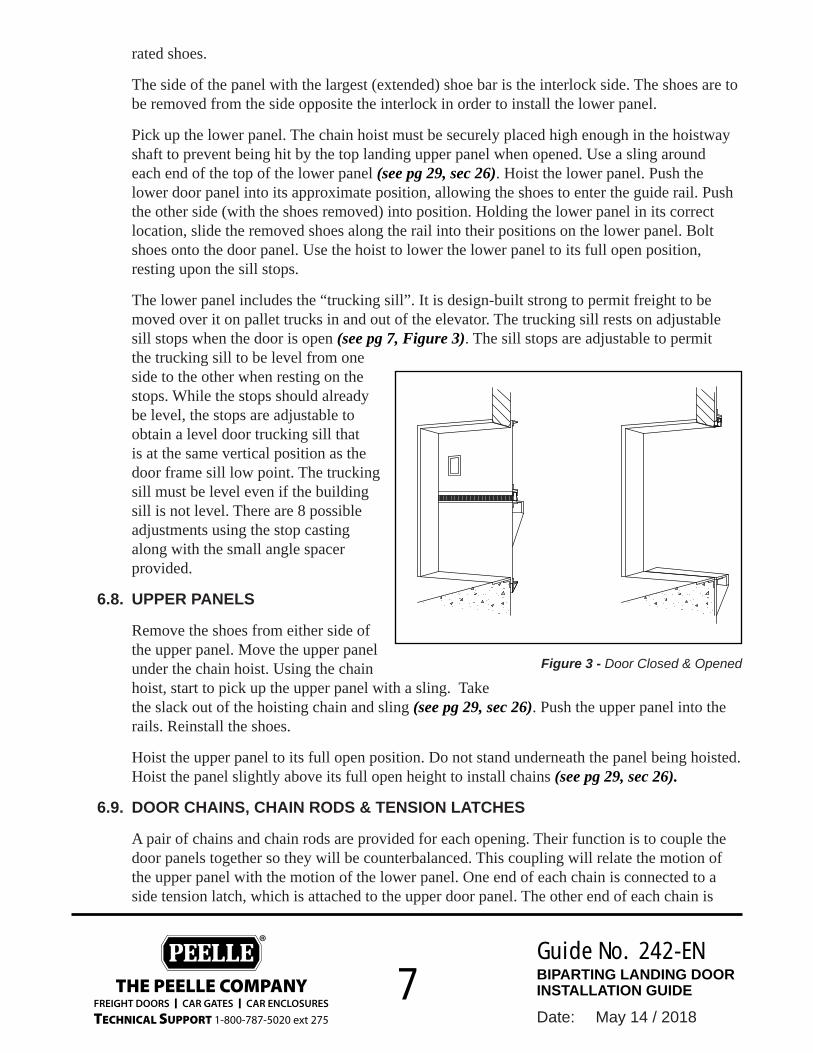
The lower panel includes the “trucking sill”. It is design-built strong to permit freight to be moved over it on pallet trucks in and out of the elevator. The trucking sill rests on adjustable sill stops when the door is open (see pg 7, Figure 3). The sill stops are adjustable to permit the trucking sill to be level from one side to the other when resting on the stops. While the stops should already be level, the stops are adjustable to obtain a level door trucking sill that is at the same vertical position as the door frame sill low point. The trucking sill must be level even if the building sill is not level. There are 8 possible adjustments using the stop casting along with the small angle spacer provided.
6.8. UPPER PANELS
Remove the shoes from either side of the upper panel. Move the upper panel under the chain hoist. Using the chain hoist, start to pick up the upper panel with a sling. Take the slack out of the hoisting chain and sling (see pg 29, sec 26). Push the upper panel into the rails. Reinstall the shoes.
Hoist the upper panel to its full open position. Do not stand underneath the panel being hoisted. Hoist the panel slightly above its full open height to install chains (see pg 29, sec 26).
6.9. DOOR CHAINS, CHAIN RODS & TENSION LATCHES
A pair of chains and chain rods are provided for each opening. Their function is to couple the door panels together so they will be counterbalanced. This coupling will relate the motion of the upper panel with the motion of the lower panel. One end of each chain is connected to a side tension latch, which is attached to the upper door panel. The other end of each chain is
Figure 3 - Door Closed & Opened

FREIGHT DOORS I CAR GATES I CAR ENCLOSURES
TECHNICAL SUPPORT 1-800-787-5020 ext 275
THE PEELLE COMPANY
® Guide No.
Date:
242-ENBIPARTING LANDING DOOR INSTALLATION GUIDE
May 14 / 20188
connected to a chain rod, which is connected to the lower panel. The chain rods are threaded to allow for chain adjustment, when needed later.
With the upper panel hoisted, install the side tension latches onto the pivots at each side and lock in place with the spring pins (see pg 32, sec 29).
Install the threaded end of the chain rod into the chain rod holder. Put one nut, a lock washer and second nut onto the threads, then cotter pin; move nuts and lock washer down to cotter pin, hold rod up temporarily with vice grips (see pg 33, sec 30).
Attach one end of the chain to the side tension latch pivot of the upper panel with a chain connector link. Pull the chain up through the sheave cover to thread the chain over the sheave. Mark and cut the chain to length at the top of the chain rod. Grind of the end of the pin and hammer out the pins. Use a chain breaker device if you have one. Attach the free end of the chain to the rod using chain connector link (see pg 33, sec 30).
Use the hoist to lower the upper panel until it is held up by the chains. Make sure that all chain connecting links are properly connected. Chain connector clip should have legs pointing downward. Wrap connecting links and connector clips at each end of the chain with the nylon tie-wraps provided (see pg 31, sec 28). Peelle door and gate chains are lubricated by the manufacturer. NO OIL or GREASE is required upon initial installation.
6.10. TO ADJUST DOOR CHAINS AND DOOR PANELS IN THIS ORDER:
After the chains are connected, the door panels must be properly adjusted. Most of the adjustment, if necessary, is accomplished by moving the nuts up on the chain as rod (see pg 38, sec 33.2). Some links of chain may have to be removed to achieve desired adjustment.
TO POSITION PANELS FOR FULL OPENINGWith the lower door panel resting evenly on both stops and the trucking sill level from side to side and at the same height as the door frame sill low point. The upper panel should be fully open (including the astragal cushion strip). Adjust chains. Remove some chain links if necessary. No portion of the astragal should project below the head-of-frame when the doors are fully open. Do not judge chain adjustment solely by the door frame sill or head-of-frame. They might not be level (do not use a level on the astragal of upper panel). Stand on lower panel; the upper panel should be the same distance from the lower panel, measured at both ends of the opening width.
TO ELIMINATE GAP BETWEEN PANELS IN CLOSED POSITIONWith the doors fully closed and with the side tension latch hooks loosened and positioned temporarily out of the way, adjust the nuts on the chain rods to eliminate the panel gap across the opening. Move nuts up on the rod of the side of the door that tends to stay apart. This provides a closed meeting between panels in the closed position. Doors properly sized for an opening must overlap the head-of-frame and the sill by 50mm [2 in].
TO LOWER THE CENTER POINT (DAY LIGHT) OF THE PANELSKeep the door panels in the same closed position (with no opening at the sill or at the head-

FREIGHT DOORS I CAR GATES I CAR ENCLOSURES
TECHNICAL SUPPORT 1-800-787-5020 ext 275
THE PEELLE COMPANY
® Guide No.
Date:
242-ENBIPARTING LANDING DOOR INSTALLATION GUIDE
May 14 / 20189
of-frame). Move nuts on both rods downward the same distance each side. Make sure the nuts are almost touching the cotter pin near the bottom. This allows for the easy future chain stretch adjustment. If there is slack in the chain, remove chain links to remove slack.
TO REMOVE CHAIN LINKSReset the lower panel on the sill stops, use a chain fall to get the upper panel fully open, make sure the nuts are almost touching the cotter pins near bottom of each chain rod, clamp the rods with vice grips positioned on top of the rod holders, disconnect the chains at the latches, remove links from both chains with a chain breaker.
Reconnect the chains. Carefully remove the chain hoist from the upper panel and remove the temporary clamps (vise grips) from the chain rods.
6.11. ADJUST PANEL BETWEEN GUIDES
Allow 3mm [1/8 in] overall side-to-side play. The side-to-side play should be the same at the top and bottom shoes of each panel to make sure the doors operate freely. There should be little need for chain adjustment if the rails are plumb and the panels are an equal distance apart vertically, both sides, when fully open. Only if necessary, adjust the “adjustable” shoes inward or outward to achieve 3mm [1/8 in] side-to-side play.
L Door panels, when opening and closing must also have their weight in balance. Do not leave the doors in an open position without a barricade. Bolt the doors closed or lock them with an interlock.
6.12. DOOR SIDE TENSION LATCHES
Side tension latches, provided on each side of the doors, minimizes separation of the door panel meeting edges when closed.
Side tension latches are important and must be set with enough tension to keep the doors from separating when closed. The latch must pivot freely. Remove any paint or burr from the pivot area and lubricate with grease or oil. Set the pivot stop bolt. To set the pivot stop bolt, the tension hook must be loosened and tightened temporarily out of the way. Loosen, but do not remove the tension hook mounting bolts. Set the stop bolt. Then reposition the hooks to pressure the door panels closed. The roller keeper should be in the proper horizontal position for the tension latch hook to be plumb when the doors are closed. If not, the upper panel and lower panel rails might not be meeting properly. Adjust if necessary. The roller keeper should also meet the latch hook in the proper vertical location. It should be snug in the lower curve of the latch.
6.13. FOR INTERLOCKS COMPONENTS AND SILLS, OPERATORS AND OTHER COMPONENTS, REFER TO SECTIONS 33.6 TO 33.11
FREIGHT DOORS I CAR GATES I CAR ENCLOSURES
TECHNICAL SUPPORT 1-800-787-5020 ext 275
THE PEELLE COMPANY
® Guide No.
Date:
242-ENBIPARTING LANDING DOOR INSTALLATION GUIDE
May 14 / 201810
Low
er R
ail
Inte
rmed
iate
Rai
lU
pper
Rai
lIn
term
edia
te R
ail
FRONTLINE "A"
REARLINE "C"
Vertical Section
Low
er R
ail
Upp
er R
ail
Upp
er R
ail
Low
er R
ail
Upp
er R
ail
Low
er R
ail
Showing various openings and rail configurations
770440-02
OP
ENIN
GH
EIG
HT
OP
EN
ING
HE
IGH
T
FRONT LINE "A"FLOOR HEIGHT
Pit
OPE
NIN
GH
EIG
HT
1st Floor
3rd Floor
4th Floor
REAR LINE "C"FLOOR HEIGHT
FLO
OR
HE
IGH
TFL
OO
R H
EIG
HT
OV
ERH
EAD
OP
EN
ING
HEI
GH
TO
PE
NIN
GH
EIG
HT
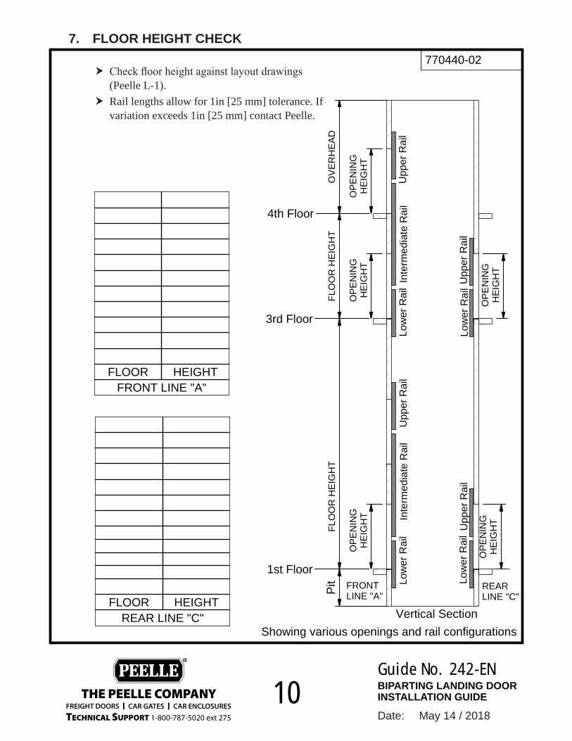
7. FLOOR HEIGHT CHECK
h Check floor height against layout drawings (Peelle L-1).
h Rail lengths allow for 1in [25 mm] tolerance. If variation exceeds 1in [25 mm] contact Peelle.

FREIGHT DOORS I CAR GATES I CAR ENCLOSURES
TECHNICAL SUPPORT 1-800-787-5020 ext 275
THE PEELLE COMPANY
® Guide No.
Date:
242-ENBIPARTING LANDING DOOR INSTALLATION GUIDE
May 14 / 201811
770440-01
PLATFORM
BOTTOMPOSITION
LANDING SILL
TOPPOSITION
A B
HEADER
ENTRANCE FRAME
8. CAR CLEARANCE CHECK
Measure the distance between the platform & entrance frame (both side) see dimension A and B. Measure at floor level and top of opening. Dimensions will be used later for adjusting and shimming the rails.
TOPBOTTOM
TOPBOTTOM
TOPBOTTOM
TOPBOTTOM
TOPBOTTOM
FLOOR POSITION A BFRONT LINE “A”
TOPBOTTOM
TOPBOTTOM
TOPBOTTOM
FLOOR POSITION A BREAR LINE “C”
FREIGHT DOORS I CAR GATES I CAR ENCLOSURES
TECHNICAL SUPPORT 1-800-787-5020 ext 275
THE PEELLE COMPANY
® Guide No.
Date:
242-ENBIPARTING LANDING DOOR INSTALLATION GUIDE
May 14 / 201812
770441-01
= =
JAMB
SQUARE
Mark The Centerline
Mark
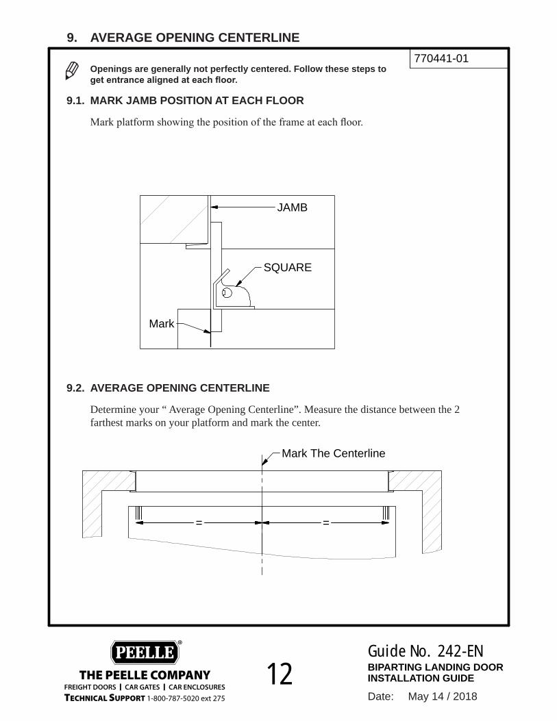
9. AVERAGE OPENING CENTERLINE
L Openings are generally not perfectly centered. Follow these steps to get entrance aligned at each floor.
9.1. MARK JAMB POSITION AT EACH FLOOR
Mark platform showing the position of the frame at each floor.
9.2. AVERAGE OPENING CENTERLINE
Determine your “ Average Opening Centerline”. Measure the distance between the 2 farthest marks on your platform and mark the center.

FREIGHT DOORS I CAR GATES I CAR ENCLOSURES
TECHNICAL SUPPORT 1-800-787-5020 ext 275
THE PEELLE COMPANY
® Guide No.
Date:
242-ENBIPARTING LANDING DOOR INSTALLATION GUIDE
May 14 / 201813
770441-02
PLATFORM
Average Center Opening
Gauge Rod
Transfred DBG Mark
Center line of Gauge Rod
Center Line of Gauge Rod
10. LOCATING CENTER OF THE OPENINGS
L DBG = Distance Between Guides
10.1. POSITION THE CENTER OF THE GAUGE ROD ONTO THE AVERAGE OPENING CENTER LINE.
10.2. NEXT TRANSFER THE DBG TO THE PLATFORM.

FREIGHT DOORS I CAR GATES I CAR ENCLOSURES
TECHNICAL SUPPORT 1-800-787-5020 ext 275
THE PEELLE COMPANY
® Guide No.
Date:
242-ENBIPARTING LANDING DOOR INSTALLATION GUIDE
May 14 / 201814
770440-04
Sill Mark
Lowest Side
Building Sill
Rail
Sill
Lowest SideProjected Sill Mark
11. BUILDING SILL LEVEL CHECK
11.1. LEVEL THE SILL
Ensure Building Sill is Level +/- 3/8” [6mm]. If sill is out more than 1/4in [6mm] have sill corrected.
11.2. IDENTIFY LOWEST SIDE
Identify and mark the lowest side of the sill and project to opposite side of entrance.
11.3. POSITION THE RAIL
When installing the first rail align the sill mark with the lowest side of the sill.
L When installing the rail, align the sill mark with the lowest side of the sill (Projected Sill Mark).
FREIGHT DOORS I CAR GATES I CAR ENCLOSURES
TECHNICAL SUPPORT 1-800-787-5020 ext 275
THE PEELLE COMPANY
® Guide No.
Date:
242-ENBIPARTING LANDING DOOR INSTALLATION GUIDE
May 14 / 201815
DETAIL C
DETAIL A
DETAIL B
DETAIL D
First Floor
Second Floor
PIT
770468-01
D
C
A
B
Right HandLeft Hand
1.00 in[25 mm]
Sill mark
AdjustableStop Casting
Spreader
Rail clipSpreader
Gauge Rod
Upper Rail
Intermediate Rail
Lower Rail
12. DOOR GUIDE RAIL INSTALLATION - OVERVIEW

FREIGHT DOORS I CAR GATES I CAR ENCLOSURES
TECHNICAL SUPPORT 1-800-787-5020 ext 275
THE PEELLE COMPANY
® Guide No.
Date:
242-ENBIPARTING LANDING DOOR INSTALLATION GUIDE
May 14 / 201816
SECTION H-HSCALE 1/125
5. Ensure rails are set vertical using a level.
A
A
G
H H
J
LM
770446-02
2. Lower Rail Installation Positioning
"Horizontal Alignemnt"
MATE RAIL WITH SET SQUARE RULESET HORIZONTAL POSITION TO D.B.G
3. Set vertical position align sill mark with building sill.
4. Align rail guide with DBG mark using set square
1. Locate job number and floor designation.
2. Clamp the lower rail to frame.
Pass type rail
Regular type rail
Building Sill
ALIGN SET SQUARE WITH D.B.GMARK
PLATFORM
Lower Rail
DBG mark
Frame
Rail guids Back of rail
Rail guids
Sill Mark
Square
Lower RailRight Hand
Clamp
Right HandFrame
Platform
13. RAIL INSTALLATION POSITIONING
FREIGHT DOORS I CAR GATES I CAR ENCLOSURES
TECHNICAL SUPPORT 1-800-787-5020 ext 275
THE PEELLE COMPANY
® Guide No.
Date:
242-ENBIPARTING LANDING DOOR INSTALLATION GUIDE
May 14 / 201817
770446-03
PLAN VIEW
1 1/2" [38mm]
5/16" [8mm] Masonary Bit
11/32" [8.5mm] Drill Thru Frame
#0629Rail Shim
#060004Rail Bolt
Hole intop of slot
EntranceFrame
Door Rail
14. RAIL BOLTING
14.1. LOWEST RAIL BOLTING
1) Drill 11/32” [8.5mm] hole into steel entrance frame. Approximately 1/2in [13mm] deep. Avoid drilling into masonry wall. When drilling through rail slot ensure hole is in top of slot.
2) Drill 5/16in [8mm] hole into masonry wall. Approximately 1 1/2in [38mm] deep3) Use 9/16” [14 mm] impact driver to install #06004 Rail Bolt. Do not use washers. Only
install rail bolts into steel entrance frames.
14.2. SHIM RAIL AS NECESSARY.
Refer back to “Car Clearance Check”.
14.3. IN ORDER TO KEEP RAILS PLUMB AND MAINTAIN THE CORRECT CAR CLEARANCE USE “0629 RAIL SHIMS”.
1) Loosen rail bolt2) Hook the rail shim onto the rail bolt3) Tighten rail bolt4) Check rail is plumb
L Maximum of 6 shims per bolt, If you require more than 6 shims weld flat bar to frame.

FREIGHT DOORS I CAR GATES I CAR ENCLOSURES
TECHNICAL SUPPORT 1-800-787-5020 ext 275
THE PEELLE COMPANY
® Guide No.
Date:
242-ENBIPARTING LANDING DOOR INSTALLATION GUIDE
May 14 / 201818
770446-14
Guide Rail
Guide Rail
Gauge Rod
Left Hand
Right Hand
15. HOW TO USE GAUGE ROD
h The gauge rod is used to correctly space the left rail from the right rail, this will allow your door panel to fit perfectly between the rails and operate smoothly.
h After installing the right side rail position, clamp the left rail onto the entrance frame.
h Using the previous steps outlining dbg and sill mark, the left rail is in the correct location.
h Before drilling and bolting the left rail hold the gauge rod level between the two rail guides.
h Hold gauge rod level between the door rails. h Slowly move the gauge rod up and down the rail, keeping the rod gauge level.

FREIGHT DOORS I CAR GATES I CAR ENCLOSURES
TECHNICAL SUPPORT 1-800-787-5020 ext 275
THE PEELLE COMPANY
® Guide No.
Date:
242-ENBIPARTING LANDING DOOR INSTALLATION GUIDE
May 14 / 201819
770446-05
SILL MARK
GAUGE ROD
16. RAIL INSTALLATION - OPPOSITE SIDE
FOLLOW THESE STEPS FOR THE OPPOSITE SIDE RAIL INSTALLATION
1) Position opposite side (left rail) (see pg 16, sec 13).2) Set vertical position for the lowest side level with opposite side (see
pg 16, sec 13) step 3.3) Ensure sill mark on left rail aligns with sill mark on the right rail.4) Use gauge rod to ensure rails ARE CORRECT distance apart.5) Drill and bolt rail into position.
L USE THE GAUGE ROD AND A LEVEL TO ENSURE SILL MARKS ARE LEVEL WITH EACH OTHER

FREIGHT DOORS I CAR GATES I CAR ENCLOSURES
TECHNICAL SUPPORT 1-800-787-5020 ext 275
THE PEELLE COMPANY
® Guide No.
Date:
242-ENBIPARTING LANDING DOOR INSTALLATION GUIDE
May 14 / 201820
770468-27
IntermediateRail
Top RailOR
SILL MARK
1" [25mm]
17. INTERMEDIATE OR TOP RAIL OVERVIEW
THE NEXT RAIL TO INSTALL WILL BE EITHER THE INTERMEDIATE OR TOP RAIL.
INTERMEDIATE RAILUse Sill Mark to position Intermediate Rail with the Landing above.
TOP RAILPosition the Top Rail 1” [25mm] above Lower Rail.
Intermediate Railshared between two floors
Top Rail is not shared between two floors
FREIGHT DOORS I CAR GATES I CAR ENCLOSURES
TECHNICAL SUPPORT 1-800-787-5020 ext 275
THE PEELLE COMPANY
® Guide No.
Date:
242-ENBIPARTING LANDING DOOR INSTALLATION GUIDE
May 14 / 201821
770446-11 8. Attach Clip Angle to Wall
Note:For sealed pits (water proof) do not use masonnary anchors, use spreaders povided.
• Use gauge rod at top and bottom of rails to ensure correct distance apart is maintained
• Use masonary anchor bolts to secure rails to wall, wherever rail clips are provided
After All Rails Are Installed
MA S
ON
A RY
Gauge Rod
Right Rail
Left Rail
1/2" x 2 1/2"Masonary
Anchor Bolt
Spreder in the pit.If the pit is sealed [Water proof]
1/2" x 2 1/2"Masonary Ancor Bolt
Gauge Rod
Left Rail
Right Rail
Spreder in the pit.If the pit is sealded[water proof]
Clip Angle
MasonryAnchor Bolt
MasonryAnchor Bolt
Clip Angle
Spreader(waterproof pits only)
18. ATTACH CLIPS ANGLES TO WALL
After all rails are installed, use gauge rod at top and bottom of rails to ensure correct distance apart is maintained.
Use masonry anchor bolts to secure rails to wall, wherever rail clips are provided.
L For sealed waterproof pits, use spreader between rails instead of wall anchors.

FREIGHT DOORS I CAR GATES I CAR ENCLOSURES
TECHNICAL SUPPORT 1-800-787-5020 ext 275
THE PEELLE COMPANY
® Guide No.
Date:
242-ENBIPARTING LANDING DOOR INSTALLATION GUIDE
May 14 / 201822
770147-02
1/2-13 HEX SERRATED FLANGE NUT1137345251/2"-13 x 1 1/4" Lg HEX HD BOLT ZP11012037924OPERATOR ASSY0569LM13OPERATOR ASSY0569RM12RIGHTHAND RAIL ASSY77014511
DESCRIPTIONPART NOQTYITEM
1
2
5
3
ManualSheave#2593
4
19. OPERATORS OR MANUAL SHEAVES
Biparting doors require Power Operators for power doors or Manual Sheaves for manually operated doors.
1) Position operators or sheaves forward in slots for regular and extended sill doors. For pass doors position the operators back on the slot.
2) Tighten bolts adjustments will be made later.
L When rails are tapped for operators use 3/4” long bolts

FREIGHT DOORS I CAR GATES I CAR ENCLOSURES
TECHNICAL SUPPORT 1-800-787-5020 ext 275
THE PEELLE COMPANY
® Guide No.
Date:
242-ENBIPARTING LANDING DOOR INSTALLATION GUIDE
May 14 / 201823
3/8"-16 HEX NUT Z113610624PLUG ROD770014813PLUG PROOF TRIGGER ASSY2356112RIGHT HAND RAIL ASSY77014211
DESCRIPTIONPART NOQTYITEM
770147-05
COMPONENT INSTALLATION
3
4
2
4
1
20. PLUG ROD INSTALLATION
1) Insert plug rod into plug proof trigger and screw rod all the way in.
L Do not tighten, adjustment will be made later.

FREIGHT DOORS I CAR GATES I CAR ENCLOSURES
TECHNICAL SUPPORT 1-800-787-5020 ext 275
THE PEELLE COMPANY
® Guide No.
Date:
242-ENBIPARTING LANDING DOOR INSTALLATION GUIDE
May 14 / 201824
DETAIL A
770147-03
3/8-16 SERRATED FLANGE NUT Z97244453/8-16 x 1 HH BOLT ZP80006144INTERLOCK AND ZONE SWITCH UB -1A NEMA 12356-59RU13INTERLOCK PLUG ROD770014812RIGHTHAND RAIL ASSY77014511
DESCRIPTIONPART NOQTYITEM
A
4
1
5
3
2
5
4
2
3
21. INTERLOCK INSTALLATION
1) Insert plug rod into bottom of interlock.2) Align interlock slots with pre-drilled
holes in rail.3) Loosely tighten the bolts. Vertical
position of interlock will be set later.

FREIGHT DOORS I CAR GATES I CAR ENCLOSURES
TECHNICAL SUPPORT 1-800-787-5020 ext 275
THE PEELLE COMPANY
® Guide No.
Date:
242-ENBIPARTING LANDING DOOR INSTALLATION GUIDE
May 14 / 201825
DETAIL A
1/2-13 HEX NUT Z13611045*Varies* 1133626417REGULAR ROLLER ARM ASSY03556224FILLER, 5/8"035527231/2-13 x 3 1/2 CARRIAGE BOLT ZP112156722RAIL ASSY77014211
DESCRIPTIONPART NOQTYITEM
A
770147-06
Interlock Roller Arm 1. Install Roller Arm on both interlocks and Mechanical Locks. Use filler provided and
tighten2. Include "S" hook for unlocking device chain nuts loosely. Adjustment will be made
later.3. Where provided install Extended Roller Arm without filler
Adjustable Roller Arm#235571 (option)
2
1
3
4
517
5
22. INTERLOCK ROLLER ARM
1) Install roller arm on both interlocks and mechanical locks. Use filler provided and tighten.
2) Where provided install adjustable extended roller arm without filler.
MAY BE NECESSARY TO CUT THE ROD

FREIGHT DOORS I CAR GATES I CAR ENCLOSURES
TECHNICAL SUPPORT 1-800-787-5020 ext 275
THE PEELLE COMPANY
® Guide No.
Date:
242-ENBIPARTING LANDING DOOR INSTALLATION GUIDE
May 14 / 201826
DETAIL DSCALE 1/7
3/8-16 SERRATED FLANGE NUT Z97244343/8-16 x 1 HH BOLT ZP80006143SPLICE PLATE03504712LEFTHAND RAIL ASSY77023511
DESCRIPTIONPART NOQTYITEM
C
D
E
770147-04
Splice Plate or Opposite Side Mechanical Lock 1. Install splice plate on doors under 10ft [3m] wide2. Install Mechanical Lock on doors 10ft [3m] wide and greater. Loosely tighten bolts
vertical position of lock will be set later
4
2
3
1
0354Mechanical Lock (option)
1
23. SPLICE PLATE & OPPOSITE SIDE LOCK
h Install splice plate or opposite side mechanical lock. h Install splice plate on doors under 10ft [3m] wide. h Install mechanical lock on doors 10ft [3m] wide and greater. Loosely tighten top bolts vertical position will be set later.

FREIGHT DOORS I CAR GATES I CAR ENCLOSURES
TECHNICAL SUPPORT 1-800-787-5020 ext 275
THE PEELLE COMPANY
® Guide No.
Date:
242-ENBIPARTING LANDING DOOR INSTALLATION GUIDE
May 14 / 201827
770147-17
1/4-20 SERRATED HEX NUT Z1137337241/4"-20 x 1" Lg HEX HD BOLT Z11012030423DOOR ENCODER IDLER257812RIGHTHAND RAIL ASSY77014511
DESCRIPTIONPART NOQTYITEM
4
2
1
3
24. POSITION ENCODER INSTALLATION
For power doors with wireless controllers install the positional encoder on the interlock side.

FREIGHT DOORS I CAR GATES I CAR ENCLOSURES
TECHNICAL SUPPORT 1-800-787-5020 ext 275
THE PEELLE COMPANY
® Guide No.
Date:
242-ENBIPARTING LANDING DOOR INSTALLATION GUIDE
May 14 / 201828
25. UNLOADING THE PANELS
Unload panels from pallets as shown to reduce the risk of bending and distorting the panels.

FREIGHT DOORS I CAR GATES I CAR ENCLOSURES
TECHNICAL SUPPORT 1-800-787-5020 ext 275
THE PEELLE COMPANY
® Guide No.
Date:
242-ENBIPARTING LANDING DOOR INSTALLATION GUIDE
May 14 / 201829
26. INSTALL THE LOWER DOOR PANEL
PLAN VIEW SHOWINGLOWER PANEL
1
2
3
L Identify the correct panel for the appropriate opening

FREIGHT DOORS I CAR GATES I CAR ENCLOSURES
TECHNICAL SUPPORT 1-800-787-5020 ext 275
THE PEELLE COMPANY
® Guide No.
Date:
242-ENBIPARTING LANDING DOOR INSTALLATION GUIDE
May 14 / 201830
27. INSTALL THE UPPER DOOR PANEL
PLAN VIEW SHOWINGPASS UPPER PANEL
PLAN VIEW SHOWING REGULAR UPPER PANEL
SWING THE SHOEBAR INTO THE RAIL AND ENGAGE THE SHOE ONTO THE GUIDE. RE-ATTACH THE SHOES.
Remove shoes from one side
1
2
3
L When installing the upper panel determine what type of upper panel you have.
REGULAR LOWERPANEL
REGULAR UPPERPANEL
LOWERPANEL WITHEXTENDEDSILL
PASS UPPERPANEL WITHFIRE LINTEL
LOWER PANEL FROM FLOOR ABOVE

FREIGHT DOORS I CAR GATES I CAR ENCLOSURES
TECHNICAL SUPPORT 1-800-787-5020 ext 275
THE PEELLE COMPANY
® Guide No.
Date:
242-ENBIPARTING LANDING DOOR INSTALLATION GUIDE
May 14 / 201831
28. CHAIN SUSPENSION OVERVIEW
1) Feed chain from outside the operator sheave through to the tension latch.
2) Connect the chain link with the spring clip legs facing down.
3) Use tie-wraps to securely hold the chain link assembly together.
4) Double check connections and remove hoisting straps.5) Two chinas required for Biparting doors
CHAIN ROD CONNECTION
TENSION LATCH CONNECTION
CHAIN PATHTYPICAL EACH
SIDE

FREIGHT DOORS I CAR GATES I CAR ENCLOSURES
TECHNICAL SUPPORT 1-800-787-5020 ext 275
THE PEELLE COMPANY
® Guide No.
Date:
242-ENBIPARTING LANDING DOOR INSTALLATION GUIDE
May 14 / 201832
TYPICAL EACH SIDE
CONNECTION LINK0180144DOOR CHAIN0180723SIDE LATCHING ASSEMBLY0669612REGULAR UPPER PANEL77010511
DESCRIPTIONPART NOQTYITEM
A
770147-23
1
2
3
4
TIE WRAP
RETAININGCLIP
SPRING PIN
AUXILIARYLOCK
LUBRICATE
29. INSTALL THE TENSION LATCH
1) Insert the Tension Latch Assy (add a bit of oil).2) Insert spring pin and make sure it fits tightly.3) Install the hook and auxiliary lock components.

FREIGHT DOORS I CAR GATES I CAR ENCLOSURES
TECHNICAL SUPPORT 1-800-787-5020 ext 275
THE PEELLE COMPANY
® Guide No.
Date:
242-ENBIPARTING LANDING DOOR INSTALLATION GUIDE
May 14 / 201833
DETAIL FSCALE 1 / 2
CONNECTION LINK0180147DOOR CHAIN01807261/8" x 1" Lg COTTER PIN74210251/2" LOCK WASHER1133626441/2"-13 HEAVY HEX NUT ZP113651043CHAIN ROD, 42"012122BI PARTING REGULAR lOWER PANEL77013511
DESCRIPTIONPART NOQTYITEM
F
770147-24
1
7
2
6
53
4
TIE WRAP
RETAININGCLIP
30. INSTALL THE CHAIN ROD
1) Insert the chain rod into the rod clip on the hangerbar.2) Screw on the nuts, lock washer and cotter pin.3) Lower nuts all the way to bottom of the rod for full
adjustment.4) Hold rod in place using vice grips (see image below).5) Cut and connect the chain.
1/8" x 1" Lg COTTER PIN74210251/2" LOCK WASHER 1133626241/2"-13 HEAVY HEX NUT ZP 113651043CHAIN ROD, 42"012122ROD CLIP012311
DESCRIPTIONPART NOQTYITEM
770468-21
5
3
4
3
1
2
1/8" x 1" Lg COTTER PIN74210251/2" LOCK WASHER 1133626241/2"-13 HEAVY HEX NUT ZP 113651043CHAIN ROD, 42"012122ROD CLIP012311
DESCRIPTIONPART NOQTYITEM
770468-21
5
3
4
3
1
2
REMOVE PIN& CUT CHAIN
L When installing chains you may need to cut off a few links if chain is too long. Use the Peelle P/N 0608 Chain Pin Extractor.
DETAIL FSCALE 1 / 2
CONNECTION LINK0180147DOOR CHAIN01807261/8" x 1" Lg COTTER PIN74210251/2" LOCK WASHER1133626441/2"-13 HEAVY HEX NUT ZP113651043CHAIN ROD, 42"012122BI PARTING REGULAR lOWER PANEL77013511
DESCRIPTIONPART NOQTYITEM
F
770147-24
1
7
2
6
53
4
TIE WRAP
RETAININGCLIP

FREIGHT DOORS I CAR GATES I CAR ENCLOSURES
TECHNICAL SUPPORT 1-800-787-5020 ext 275
THE PEELLE COMPANY
® Guide No.
Date:
242-ENBIPARTING LANDING DOOR INSTALLATION GUIDE
May 14 / 201834
770480-04
WASHER, LOCK, 3/8"800005243/8"-16 x 1 1/4" HH BOLT11012034523ROLLER KEEPER ASSY0659222RATCHET PIECE23553411
DESCRIPTIONPART NOQTYITEM
2
1
34
035501 Shim may berequired between RatchetPiece and Hangerbar
31. RATCHET PIECE AND ROLLER KEEPER
Install the roller keeper and ratchet piece. use two shims for initial installation. Position will be adjusted later.

FREIGHT DOORS I CAR GATES I CAR ENCLOSURES
TECHNICAL SUPPORT 1-800-787-5020 ext 275
THE PEELLE COMPANY
® Guide No.
Date:
242-ENBIPARTING LANDING DOOR INSTALLATION GUIDE
May 14 / 201835
32. EMERGENCY UNLOCKING DEVICES Door Emergency Unlocking Devices are provided for each landing except jurisdictions which restrict their use. Check local code and Peelle layout Drawing L-1. The unlocking device is used to unlock a hoistway landing door for access to the hoistway shaft by authorized personnel. It is mounted on the wall next to the door. It is operated by a key that unlocks a box and exposes a chain. The chain is pulled to unlock the door. See (Figure 4).
To install the unlocking device, a hole must be drilled through the building wall for the chain. Use an electric hammer drill. Make sure the hole is drilled so that the unlocking device pull chain will meet the interlock roller. Attach the chain to the interlock roller arm with a 1/2 in nut see (Figure 4). When the device cover is locked in closed position, there should be enough slack in the chain to let the locking arm rest in its locked position.
For power doors, a switch inside the unlocking device prevents power door operation when the door unlocking device is unlocked. Make sure power for door operation is not available after the key that unlocks the device is turned and the chain is pulled. Manual re-activation of door operation is required. If power is available at this time, check the electrical connection of the wires to the unlocking device and the door zone contacts.
The door unlocking device is not to be confused with an access switch, as elevator operation must be completely unavailable when the door unlocking device is in use. Unlocking devices are used instead of access switches when certain requirements are met.
ROLLER ARM
HOLE THROUGH
WALL
INTERLOCK
UNLOCKING DEVICE
1/2 IN NUTFigure 4 - Unlocking Device

FREIGHT DOORS I CAR GATES I CAR ENCLOSURES
TECHNICAL SUPPORT 1-800-787-5020 ext 275
THE PEELLE COMPANY
® Guide No.
Date:
242-ENBIPARTING LANDING DOOR INSTALLATION GUIDE
May 14 / 201836
770147-22
33. FINAL ADJUSTMENTS
OPERATORS33.1
INTERLOCK SETTINGS33.6, 33.7, 33.8, 33.9, 33.10, 33.11
TENSION LATCH33.5
LEVEL PANELS33.2
SIDE TO SIDE PLAY33.4
LOWER PANEL ADJUSTMENT33.3
PLUGGING DEVICE33.6
PERFORM THE FINAL ADJUSTMENTS ON THE LISTED COMPONENTS.

FREIGHT DOORS I CAR GATES I CAR ENCLOSURES
TECHNICAL SUPPORT 1-800-787-5020 ext 275
THE PEELLE COMPANY
® Guide No.
Date:
242-ENBIPARTING LANDING DOOR INSTALLATION GUIDE
May 14 / 201837
2593 MANUAL SHEAVE
770480-05
ADJUSTMENTSLOTS
ADJUSTMENTSLOTS
33.1. OPERATOR ADJUSTMENT
Adjust the door operator using the mounting slots, ensure the center of sheave and chain rod are in line (keep door chain perfectly vertical).

FREIGHT DOORS I CAR GATES I CAR ENCLOSURES
TECHNICAL SUPPORT 1-800-787-5020 ext 275
THE PEELLE COMPANY
® Guide No.
Date:
242-ENBIPARTING LANDING DOOR INSTALLATION GUIDE
May 14 / 201838
770514-01
33.2. LEVEL THE PANELS
Check the opening and closing sequence and ensure panels are level and parallel with each other during the full open and close operation.
h Eliminate gap between panels in closed position. With the doors fully closed and with the side tension latch hooks loosened and positioned temporarily out of the way, adjust the nuts on the chain rods to eliminate the panel gap across the opening.
h Move nuts up on the rod of the side of the door that tends to stay apart. This provides a closed meeting between panels in the closed position.
h With door panels closed. Move nuts on both rods downward the same distance each side. Move nuts down to cotter pin. This allows for the easy future chain stretch adjustment. If there is slack in the chain, remove chain links.
CHAIN ROD NUTS

FREIGHT DOORS I CAR GATES I CAR ENCLOSURES
TECHNICAL SUPPORT 1-800-787-5020 ext 275
THE PEELLE COMPANY
® Guide No.
Date:
242-ENBIPARTING LANDING DOOR INSTALLATION GUIDE
May 14 / 201839
770468-23
04203Adjustable Stop Angle
04202Adjustable Stop Casting
Stop Plate
33.3. LOWER PANEL ADJUSTMENT
Ensure Lower Panel Trucking Sill is level with the building sill.
If final adjustment is needed, adjust the 04204 Sill Stop Casting, to raise or lower the panel open position.
There is an 8-way adjustment by flipping, rotating and spacing the stop casting.
L Move to top if necessary

FREIGHT DOORS I CAR GATES I CAR ENCLOSURES
TECHNICAL SUPPORT 1-800-787-5020 ext 275
THE PEELLE COMPANY
® Guide No.
Date:
242-ENBIPARTING LANDING DOOR INSTALLATION GUIDE
May 14 / 201840
770147-21
1/16"[2 mm]
Guide Rail
Upper Panel
Lower Panel
Max Panel Movement1/8" [3 mm]
Between Guid Rails
Adjust Guide Shoeusing slots
33.4. SIDE TO SIDE PLAY
Guide shoes have angled slots.
Adjust the gap between Guide Shoe and rail to 1/16” [1.58 mm] each side.
Allow Maximum panel movement between guides 1/8” [3.175 mm].

FREIGHT DOORS I CAR GATES I CAR ENCLOSURES
TECHNICAL SUPPORT 1-800-787-5020 ext 275
THE PEELLE COMPANY
® Guide No.
Date:
242-ENBIPARTING LANDING DOOR INSTALLATION GUIDE
May 14 / 201841
LOOSEN BOLTSTO ADJUST (PIVOT)
THE TENSION LATCH
770468-26
SET STOPBOLT 3/4"
[10 mm]
33.5. TENSION LATCH ADJUSTMENT
Bring panels together slowly and position the tension latch point just off center of the roller keeper.
Bring panels closer together, ensure the tension latch pivots out and around the roller keeper.
When door panels are in the fully closed the tension latch should be snug against the roller keeper.
LOOSEN BOLTSTO ADJUST (PIVOT)
THE TENSION LATCH
770468-26
SET STOPBOLT 3/4"
[10 mm]

FREIGHT DOORS I CAR GATES I CAR ENCLOSURES
TECHNICAL SUPPORT 1-800-787-5020 ext 275
THE PEELLE COMPANY
® Guide No.
Date:
242-ENBIPARTING LANDING DOOR INSTALLATION GUIDE
May 14 / 201842
33.6. ADJUST THE TAMPER RESISTANT PLUGGING DEVICE
The tamper resistant plugging device is made up of two components, the plugging rod and the plugging trigger.
The plugging rod is cut to the proper length for the door from the factory. It must be installed before the lock is pinned into its vertical fixed position.
Thread the plugging rod into the plugging trigger until it bottoms out. The plugging trigger can be found on the door rail below the opening. Loosen and slide the interlock so that the plugging rod inserts into the hole. Slide the interlock into place and turn the rod for proper adjustment. Lock the rod in place with the supplied nuts.
Figure 5 - Plugging Trigger

FREIGHT DOORS I CAR GATES I CAR ENCLOSURES
TECHNICAL SUPPORT 1-800-787-5020 ext 275
THE PEELLE COMPANY
® Guide No.
Date:
242-ENBIPARTING LANDING DOOR INSTALLATION GUIDE
May 14 / 201843
33.7. INSTALL KEEPER HOOK, UPPER PANEL HOOK AND SET POSITION OF THE INTERLOCK
The keeper hook for the interlock must be bolted to the hanger bar on the lower panel. This lower panel lock keeper hook and the upper panel lock keeper, prevent the door panels from being opened when the interlock roller is extended (locked).
Set the interlock ratchet 8mm [5/16in] below the lower keeper hook with the doors closed, chains adjusted and side-tension-latches working; set the 8mm [5/16in] dimension by moving the interlock plate up or down in the slots, then securely tightening the bolts.
Ensure the keeper hook has at least 8mm [5/16in] locking engagement with the top of the ratchet. (see pg 43, Figure 6). Ensure keeper hook clears the ratchet teeth while opening the door. Use shims to space the hook in or out to obtain clearance if necessary.
Attach/adjust upper panel keeper hook to side-tension-latch on interlock side as shown in (Figure 6). There is one style keeper for regular doors (066975) and another for pass-type doors (066976). If door has side-opposite-lock (mechanical lock for wide doors) on the side opposite the interlock, attach/adjust an upper panel lock keeper also on that side, in addition to a lower panel keeper hook.
Add pinning bolts (see pg 44, Figure 7) drill 8mm [5/16in] holes (through the holes supplied in the rail) into the interlock plate, near the middle. Then tap interlock plate M10 or 3/8 UNC. Insert 20mm or 3/4in long roundhead bolts (see pg 44, Figure 7). The interlock vertical position should never change. From this point on only the panel position can be adjusted.
Figure 6 - Locking Arm

FREIGHT DOORS I CAR GATES I CAR ENCLOSURES
TECHNICAL SUPPORT 1-800-787-5020 ext 275
THE PEELLE COMPANY
® Guide No.
Date:
242-ENBIPARTING LANDING DOOR INSTALLATION GUIDE
May 14 / 201844
2"
[5
1m
m]
7 7
/8"
[2
00
mm
]
7/8
" [
22
mm
]
3" [76mm]
PIN THE INTERLOCK AFTER INTERLOCK HAS BEEN SET AT THE PROPER HEIGHT TO SUIT DOOR KEEPER HOOK
DRILL AND TAP FOR 3/8”-16 x 3/4” RH BOLT[M10 x 20]
33.8. PIN THE INTERLOCK
Figure 7 - Pining the Lock

FREIGHT DOORS I CAR GATES I CAR ENCLOSURES
TECHNICAL SUPPORT 1-800-787-5020 ext 275
THE PEELLE COMPANY
® Guide No.
Date:
242-ENBIPARTING LANDING DOOR INSTALLATION GUIDE
May 14 / 201845
Step 1 Step 2 Step 3 Step 4
33.9. ADJUST THE DOOR CLOSE CAM AND KICK-OUT ARM
Set the door closed cam to open the DC contact when the door panels are more than 20mm [3/4 in] apart. A handy guide for the DC contact setting is to put the hook in the “first” notch see (see pg 45, Figure 8) step 1. The DC contact should be slightly open. At this setting, the contact should be definitely made (closed) when the doors are closed. Check that the contact is still made when the door is pushed toward the hoistway shaft from the room side approximately 3mm [1/8 in]. The cam should have 2mm [1/16 in] horizontal free movement away from the hanger bar when the doors are closed (see pg 45, Figure 8) step 2 for normal door closed position see (see pg 45, Figure 8) step 3.
Adjust kick-out arm separately to positively open DC contact when the door panels move more than 20mm [3/4 in] apart (see pg 45, Figure 8) step 4, the DC contact should never make when the door keeper hook is in an unlocked position. The DC contact is to be held mechanically open by the tamper resistant plugging device. Replace the DC contact cover on the contact box as soon as possible to make sure the insulating paper does not get torn.
Figure 8 - DC Cam Settings

FREIGHT DOORS I CAR GATES I CAR ENCLOSURES
TECHNICAL SUPPORT 1-800-787-5020 ext 275
THE PEELLE COMPANY
® Guide No.
Date:
242-ENBIPARTING LANDING DOOR INSTALLATION GUIDE
May 14 / 201846
33.10. SET THE ROLLER ARM
The roller arm of the interlock is normally attached in the factory. Make sure locking arm spring is in place and working.
Ensure locking arm falls forward, easily and fully and rests on the mechanical stop (see pg 46, Figure 9). Stop block (located on the contact shaft, in the upper interlock box) should just touch the bottom fixed guide block, when the locking arm is fully dropped (see pg 46, Figure 10).
Contact shaft should drop enough to allow the locking arm to fall forwards fully and rest on the mechanical stop. Adjust the stop block and / or raise the upper interlock box to hold the factory 60mm [2-1/2 in] dimension.
Stand on landing side and make sure the door panels cannot be shaken open when they are closed and locked (retiring cam held up or elevator away). Try again while you are pushing the lower panel toward the elevator (retiring cam held up or elevator away).
Figure 9 - Roller Arm Setting
Figure 10 - Contact Switch Assembly

FREIGHT DOORS I CAR GATES I CAR ENCLOSURES
TECHNICAL SUPPORT 1-800-787-5020 ext 275
THE PEELLE COMPANY
® Guide No.
Date:
242-ENBIPARTING LANDING DOOR INSTALLATION GUIDE
May 14 / 201847
33.11. ADJUST THE TAMPER RESISTANT PLUGGING DEVICE
The trigger portion of the device is actuated by the opening movement of the lower door panel, the trigger then pushes the rod into the DC contact (lower box). The rod movement keeps the DC contact open which prevents the DC contact from being closed until the lower panel is returned to the closed position. The rod should be set to lock the contact arm immediately after the contact arm moves to the full open position. The rod should hold “Door Closed” DC contact open as soon as the contact opens.
Figure 11 - Plug Rod Setting Closed
Figure 12 - Plug Rod Setting Open

FREIGHT DOORS I CAR GATES I CAR ENCLOSURES
TECHNICAL SUPPORT 1-800-787-5020 ext 275
THE PEELLE COMPANY
® Guide No.
Date:
242-ENBIPARTING LANDING DOOR INSTALLATION GUIDE
May 14 / 2018


![mlit.go.jp · 2019. 2. 1. · [235] [235) 123 [24.2] [240] [240] [24.3] [242 [242 [242] [242) [245 43] [242 (242 [242] [24.2] [ú.2] [242] [242 [240] [242] 27 087 087 [24.6] [24.6]](https://img.pdfslide.net/doc/110x75/613019b41ecc51586943e0fb/mlitgojp-2019-2-1-235-235-123-242-240-240-243-242-242-242.jpg)