Embed Size (px)
Citation preview

25-22-92 Page HI-1Oct 1/05
Component Maintenance Manual41192011
Component Maintenance Manual41192011
HIGHLIGHTS
To all holders of 4/Flight Industries Component Maintenance Manual 25-22-92:
This letter transmits Revision 1, dated Oct 1/05.
This is a complete revision. Please remove and replace the entire manual with Revision 1.
The changes made to the manual during this revision are described in the table that follows:
Location Description of Change
T-1 Added Revision 1 and date.
RR-1 Added Revision 1 and date.
SBL-1 Added Service Bulletins 41190000-25-17 and -18.
LEP-1, LEP-2 Inserted Revision 1 dates.
TOC-1 - TOC-4 Updated for Revision 1.
LOF-1 Updated for Revision 1.
LOT-1 Updated for Revision 1.
1 - 3 Revised description, leading particulars and Figure 1.
1002 Revised note.
1003 Revised cable listing.
1004 Updated item number.
2002 Revised wiring diagram.
3001 - 3008 Revised disassembly procedures.
4002, 4003, 4006 Revised cleaning procedures.
5002, 5003 Updated item numbers. Added check procedures.
7001 - 7007, 7009 - 7016 Revised assembly procedures.
9001 - 9003 Revised consumable materials and special tools and test equipment.
10007 - 10013 Revised numerical index to reflect Revision 1 changes.
10016 - 10019 Revised IPL Figure 1 and listing to incorporate manufacturing changes.
10020 - 10024 Added IPL Figure 1A and listing to incorporate manufacturing changes.
10025 - 10027 Revised IPL Figure 2 and listing.

25-22-92 Page HI-2Oct 1/05
Component Maintenance Manual41192011
10028 - 10032 Revised IPL Figure 3 and listing to incorporate manufacturing
changes.
10034 - 10037 Revised IPL Figure 4 and listing to incorporate manufacturing changes.
10038, 10039 Deleted IPL Figure 5.
10040 - 10041 Added IPL Figure 5A and listing to incorporate manufacturing changes.
10042, 10043 Revised IPL Figure 6 and listing.
10044 - 10051 Revised IPL Figure 7 and listing to incorporate manufacturing changes.
10052, 10053 Revised IPL Figure 8 and listing to incorporate manufacturing changes.
10055 - 10059 Added IPL Figure 8A and listing.
10060 - 10063 Revised IPL Figure 9 and listing to incorporate manufacturing changes.
10064 - 10072 Revised IPL Figure 10 and listing to incorporate manufacturing changes.
Location Description of Change
25-22-92CAGE Code: 34696
Page T-1Basic Issue: May 1/05
Revision: 1, Oct 1/05
41192011
COMPONENT MAINTENANCE MANUAL WITH
ILLUSTRATED PARTS LIST
Double Seat Assembly
PART NUMBERS41192011-10141192011-10241192011-10341192011-10441192011-10541192011-10641192011-10741192011-108

Component Maintenance Manual41192011
25-22-92 Page T-2Oct 1/05
THIS PAGE IS INTENTIONALLY LEFT BLANK

25-22-92 Page RR-1Oct 1/05
Component Maintenance Manual41192011
RECORD OF REVISIONS
Retain this record in the front of the manual. Upon receipt of a revision, insert the revised pages in the manual, enter the revision number, revision date, inserted by, and date inserted.
RevisionNumber
RevisionDate
InsertedBy
DateInserted
1 Oct 1/05

Component Maintenance Manual41192011
25-22-92 Page RR-2Oct 1/05
THIS PAGE IS INTENTIONALLY LEFT BLANK

25-22-92 Page RTR-1Oct 1/05
Component Maintenance Manual41192011
RECORD OF TEMPORARY REVISIONS
This page gives a record of temporary revisions. When you receive a temporary revision, insert the temporary revision in the manual opposite the first affected page and log the information in the table given below. Remove the temporary revision when the manual is revised.
NOTE: Temporary revisions are printed on yellow paper with the heading TEMPORARY REVISION.
There are no temporary revisions for this manual.

25-22-92 Page RTR-2Oct 1/05
Component Maintenance Manual41192011
THIS PAGE IS INTENTIONALLY LEFT BLANK

25-22-92 Page SBL-1Oct 1/05
Component Maintenance Manual41192011
SERVICE BULLETIN LIST
Service bulletins and/or letters applicable to the component that are included in this manual are given below.
EffectSB
NumberSB Rev.Number Title
Mod.Number
IssueDate
IncorporatedCMM Rev.
- 41190000-25-17
EQUIPMENT FURNISHING - Passenger Compartment - Install Wire Harness - PC Outlet Jumper Assembly
41192011 Jun 6/05
1
- 41190000-25-18
EQUIPMENT FURNISHING - Passenger Compartment - Verify Installation of AC Outlet Unit Seat Assemblies
41192011 Jun 13/05
1

25-22-92 Page SBL-2Oct 1/05
Component Maintenance Manual41192011
THIS PAGE IS INTENTIONALLY LEFT BLANK

25-22-92 Page LEP-1Oct 1/05
Subject Page Date Subject Page Date
Component Maintenance Manual41192011
LIST OF EFFECTIVE PAGES
The total number of pages in this manual is 152.
Title T-1 Oct 1/05T-2 Oct 1/05
Record of Revisions RR-1 Oct 1/05RR-2 Oct 1/05
Record of Temporary RTR-1 Oct 1/05Revisions RTR-2 Oct 1/05Service Bulletin List SBL-1 Oct 1/05
SBL-2 Oct 1/05List of Effective Pages LEP-1 Oct 1/05
LEP-2 Oct 1/05Table of Contents TOC-1 Oct 1/05
TOC-2 Oct 1/05TOC-3 Oct 1/05TOC-4 Oct 1/05
List of Figures LOF-1 Oct 1/05LOF-2 Oct 1/05
List of Tables LOT-1 Oct 1/05LOT-2 Oct 1/05
Introduction Intro-1 Oct 1/05Intro-2 Oct 1/05Intro-3 Oct 1/05Intro-4 Oct 1/05
Description and 1 Oct 1/05Operation 2 Oct 1/05
3 Oct 1/054 Oct 1/05
Testing and 1001 Oct 1/05Fault Isolation 1002 Oct 1/05
1003 Oct 1/051004 Oct 1/05
Schematics and 2001 Oct 1/05Wiring Diagrams 2002 Oct 1/05Disassembly 3001 Oct 1/05
3002 Oct 1/053003 Oct 1/053004 Oct 1/053005 Oct 1/053006 Oct 1/053007 Oct 1/053008 Oct 1/05
Cleaning 4001 Oct 1/054002 Oct 1/05
4003 Oct 1/054004 Oct 1/054005 Oct 1/054006 Oct 1/05
Inspection/Check 5001 Oct 1/055002 Oct 1/055003 Oct 1/055004 Oct 1/05
Repair 6001 Oct 1/056002 Oct 1/056003 Oct 1/056004 Oct 1/056005 Oct 1/056006 Oct 1/05
Assembly 7001 Oct 1/057002 Oct 1/057003 Oct 1/057004 Oct 1/057005 Oct 1/057006 Oct 1/057007 Oct 1/057008 Oct 1/057009 Oct 1/057010 Oct 1/057011 Oct 1/057012 Oct 1/057013 Oct 1/057014 Oct 1/057015 Oct 1/057016 Oct 1/057017 Oct 1/057018 Oct 1/05
Fits and Clearances 8001 Oct 1/058002 Oct 1/05
Special Tools Fixtures 9001 Oct 1/05Equipment and 9002 Oct 1/05Consumables 9003 Oct 1/05
9004 Oct 1/05Illustrated Parts List 10001 Oct 1/05
10002 Oct 1/0510003 Oct 1/0510004 Oct 1/0510005 Oct 1/0510006 Oct 1/05

25-22-92 Page LEP-2Oct 1/05
Subject Page Date Subject Page Date
Component Maintenance Manual41192011
10007 Oct 1/0510008 Oct 1/0510009 Oct 1/0510010 Oct 1/0510011 Oct 1/0510012 Oct 1/0510013 Oct 1/0510014 Oct 1/0510015 Oct 1/0510016 Oct 1/0510017 Oct 1/0510018 Oct 1/0510019 Oct 1/0510020 Oct 1/0510021 Oct 1/0510022 Oct 1/0510023 Oct 1/0510024 Oct 1/0510025 Oct 1/0510026 Oct 1/0510027 Oct 1/0510028 Oct 1/0510029 Oct 1/0510030 Oct 1/0510031 Oct 1/0510032 Oct 1/0510033 Oct 1/0510034 Oct 1/0510035 Oct 1/0510036 Oct 1/0510037 Oct 1/0510038 Oct 1/0510039 Oct 1/0510040 Oct 1/0510041 Oct 1/0510042 Oct 1/0510043 Oct 1/05
10044 Oct 1/0510045 Oct 1/0510046 Oct 1/0510047 Oct 1/0510048 Oct 1/0510049 Oct 1/0510050 Oct 1/0510051 Oct 1/0510052 Oct 1/0510053 Oct 1/0510054 Oct 1/0510055 Oct 1/0510056 Oct 1/0510057 Oct 1/0510058 Oct 1/0510059 Oct 1/0510060 Oct 1/0510061 Oct 1/0510062 Oct 1/0510063 Oct 1/0510064 Oct 1/0510065 Oct 1/0510066 Oct 1/0510067 Oct 1/0510068 Oct 1/0510069 Oct 1/0510070 Oct 1/0510071 Oct 1/0510072 Oct 1/05

25-22-92 Page TOC-1Oct 1/05
Component Maintenance Manual41192011
Subject Page
TABLE OF CONTENTS
HIGHLIGHTS . . . . . . . . . . . . . . . . . . . . . . . . . . . . . . . . . . . . . . . . . . . . . . . . . . . . . . . . . . . . . HI-1
RECORD OF REVISIONS . . . . . . . . . . . . . . . . . . . . . . . . . . . . . . . . . . . . . . . . . . . . . . . . . . .RR-1
RECORD OF TEMPORARY REVISIONS . . . . . . . . . . . . . . . . . . . . . . . . . . . . . . . . . . . . . .RTR-1
SERVICE BULLETIN LIST . . . . . . . . . . . . . . . . . . . . . . . . . . . . . . . . . . . . . . . . . . . . . . . . . SBL-1
LIST OF EFFECTIVE PAGES . . . . . . . . . . . . . . . . . . . . . . . . . . . . . . . . . . . . . . . . . . . . . . . LEP-1
TABLE OF CONTENTS . . . . . . . . . . . . . . . . . . . . . . . . . . . . . . . . . . . . . . . . . . . . . . . . . . . TOC-1
LIST OF FIGURES . . . . . . . . . . . . . . . . . . . . . . . . . . . . . . . . . . . . . . . . . . . . . . . . . . . . . . . . LOF-1
LIST OF TABLES . . . . . . . . . . . . . . . . . . . . . . . . . . . . . . . . . . . . . . . . . . . . . . . . . . . . . . . . . LOT-1
INTRODUCTION
TASK 25-22-92-99F-801-A GENERAL INFORMATION . . . . . . . . . . . . . . . . . . . . . . . . . . Intro-1Subtask 25-22-92-99F-001-A001 Scope . . . . . . . . . . . . . . . . . . . . . . . . . . . . . . . . . . . . . Intro-1Subtask 25-22-92-99F-002-A001 Product Support Services. . . . . . . . . . . . . . . . . . . . . . Intro-1Subtask 25-22-92-99F-003-A001 Usage Guide. . . . . . . . . . . . . . . . . . . . . . . . . . . . . . . . Intro-1Subtask 25-22-92-99F-004-A001 Verification Dates . . . . . . . . . . . . . . . . . . . . . . . . . . . .Intro-2Subtask 25-22-92-99F-005-A001 Abbreviations Acronyms and Unit Symbols . . . . . . . . Intro-2
DESCRIPTION AND OPERATION
TASK 25-22-92-870-801-A DESCRIPTION . . . . . . . . . . . . . . . . . . . . . . . . . . . . . . . . . . . . . . . 1Subtask 25-22-92-870-001-A001 Physical Description . . . . . . . . . . . . . . . . . . . . . . . . . . . . . . 1
TASK 25-22-92-870-802-A OPERATION . . . . . . . . . . . . . . . . . . . . . . . . . . . . . . . . . . . . . . . . . 2Subtask 25-22-92-870-002-A001 Operation . . . . . . . . . . . . . . . . . . . . . . . . . . . . . . . . . . . . . . 2
TASK 25-22-92-870-803-A LEADING PARTICULARS. . . . . . . . . . . . . . . . . . . . . . . . . . . . . . . 2Subtask 25-22-92-870-003-A001 Leading Particulars . . . . . . . . . . . . . . . . . . . . . . . . . . . . . . . 2
TESTING AND FAULT ISOLATION
TASK 25-22-92-700-801-A GENERAL TESTING INFORMATION. . . . . . . . . . . . . . . . . . . 1001Subtask 25-22-92-700-001-A001 General Information . . . . . . . . . . . . . . . . . . . . . . . . . . . 1001
TASK 25-22-92-940-811-A MATERIALS AND TEST EQUIPMENT . . . . . . . . . . . . . . . . . . 1001Subtask 25-22-92-700-002-A001 Consumable Materials . . . . . . . . . . . . . . . . . . . . . . . . . 1001Subtask 25-22-92-94B-011-A001 Test Equipment . . . . . . . . . . . . . . . . . . . . . . . . . . . . . . 1001

25-22-92 Page TOC-2Oct 1/05
Component Maintenance Manual41192011
Subject Page
TASK 25-22-92-700-802-A TESTING PROCEDURES. . . . . . . . . . . . . . . . . . . . . . . . . . . . 1001Subtask 25-22-92-700-003-A001 Foodtray Test . . . . . . . . . . . . . . . . . . . . . . . . . . . . . . . . 1001Subtask 25-22-92-700-004-A001 Lap Belt Assembly Test . . . . . . . . . . . . . . . . . . . . . . . . 1002Subtask 25-22-92-700-005-A001 Seat Recline Test . . . . . . . . . . . . . . . . . . . . . . . . . . . . . 1002Subtask 25-22-92-700-006-A001 Recline Armrest Pivot Test . . . . . . . . . . . . . . . . . . . . . . 1003Subtask 25-22-92-700-008-A001 Bottom Cushion Flotation Test . . . . . . . . . . . . . . . . . . . 1003Subtask 25-22-92-700-009-A001 IFE Cable Continuity Checks . . . . . . . . . . . . . . . . . . . . 1003
TASK 25-22-92-700-803-A FAULT ISOLATION PROCEDURES. . . . . . . . . . . . . . . . . . . . 1003Subtask 25-22-92-810-001-A001 Fault Isolation . . . . . . . . . . . . . . . . . . . . . . . . . . . . . . . . 1003
SCHEMATICS AND WIRING DIAGRAMS
TASK 25-22-92-99F-821-A GENERAL INFORMATION . . . . . . . . . . . . . . . . . . . . . . . . . . . 2001Subtask 25-22-92-99F-021-A01 General Information . . . . . . . . . . . . . . . . . . . . . . . . . . . . 2001
TASK 25-22-92-99F-822-A OPERATIONAL SCHEMATIC. . . . . . . . . . . . . . . . . . . . . . . . . 2001Subtask 25-22-92-99F-022-A01 Schematics . . . . . . . . . . . . . . . . . . . . . . . . . . . . . . . . . . . 2001
DISASSEMBLY
TASK 25-22-92-000-801-A GENERAL DISASSEMBLY INFORMATION. . . . . . . . . . . . . . 3001Subtask 25-22-92-000-001-A001 General Information . . . . . . . . . . . . . . . . . . . . . . . . . . . 3001
TASK 25-22-92-940-802-A MATERIALS AND TOOLS . . . . . . . . . . . . . . . . . . . . . . . . . . . 3001Subtask 25-22-92-94A-002-A001 Consumable Materials . . . . . . . . . . . . . . . . . . . . . . . . . 3001Subtask 25-22-92-94B-003-A001 Special Tools . . . . . . . . . . . . . . . . . . . . . . . . . . . . . . . . 3001
TASK 25-22-92-000-003-A DISASSEMBLY PROCEDURES. . . . . . . . . . . . . . . . . . . . . . . 3001Subtask 25-22-92-000-004-A001 Seat Assembly Disassembly . . . . . . . . . . . . . . . . . . . . 3001
CLEANING
TASK 25-22-92-100-801-A GENERAL INFORMATION FOR CLEANING . . . . . . . . . . . . . 4001Subtask 25-22-92-100-001-A001 General Information . . . . . . . . . . . . . . . . . . . . . . . . . . . 4001
TASK 25-22-92-100-802-A SAFETY PRECAUTIONS . . . . . . . . . . . . . . . . . . . . . . . . . . . . 4001Subtask 25-22-92-100-002-A001 Safety Precautions . . . . . . . . . . . . . . . . . . . . . . . . . . . . 4001
TASK 25-22-92-940-841-A MATERIALS AND SPECIAL TOOLS . . . . . . . . . . . . . . . . . . . 4001Subtask 25-22-92-94A-041-A001 Consumable Materials . . . . . . . . . . . . . . . . . . . . . . . . . 4001Subtask 25-22-92-94B-041-A001 Special Tools . . . . . . . . . . . . . . . . . . . . . . . . . . . . . . . . 4003
TASK 25-22-92-100-803-A CLEANING PROCEDURES . . . . . . . . . . . . . . . . . . . . . . . . . . 4003Subtask 25-22-92-100-004-A001 Molded Plastic Cleaning . . . . . . . . . . . . . . . . . . . . . . . . 4003Subtask 25-22-92-100-005-A001 Metal Part Cleaning . . . . . . . . . . . . . . . . . . . . . . . . . . . 4004Subtask 25-22-92-100-006-A001 Adhesive Removal Procedures . . . . . . . . . . . . . . . . . . 4005Subtask 25-22-92-100-007-A001 Fabric Cleaning . . . . . . . . . . . . . . . . . . . . . . . . . . . . . . 4006

25-22-92 Page TOC-3Oct 1/05
Component Maintenance Manual41192011
Subject Page
INSPECTION/CHECK
TASK 25-22-92-200-801-A GENERAL . . . . . . . . . . . . . . . . . . . . . . . . . . . . . . . . . . . . . . . . 5001Subtask 25-22-92-200-001-A001 General Information . . . . . . . . . . . . . . . . . . . . . . . . . . . 5001
TASK 25-22-92-940-811-A MATERIALS AND TOOLS . . . . . . . . . . . . . . . . . . . . . . . . . . . 5001Subtask 25-22-92-94A-051-A001 Consumable Materials . . . . . . . . . . . . . . . . . . . . . . . . . 5001Subtask 25-22-92-94B-051-A001 Special Tools . . . . . . . . . . . . . . . . . . . . . . . . . . . . . . . . 5001
TASK 25-22-92-200-802-A CHECK PROCEDURES . . . . . . . . . . . . . . . . . . . . . . . . . . . . . 5001Subtask 25-22-92-200-002-A001 Check Procedures . . . . . . . . . . . . . . . . . . . . . . . . . . . . 5001
REPAIR
TASK 25-22-92-300-801-A GENERAL REPAIR INFORMATION . . . . . . . . . . . . . . . . . . . . 6001Subtask 25-22-92-300-001-A001 General Information . . . . . . . . . . . . . . . . . . . . . . . . . . . 6001
TASK 25-22-92-940-801-A MATERIALS AND TOOLS. . . . . . . . . . . . . . . . . . . . . . . . . . . . 6001Subtask 25-22-92-94A-001-A001 Consumable Materials . . . . . . . . . . . . . . . . . . . . . . . . . 6001Subtask 25-22-92-94B-006-A001 Special Tools . . . . . . . . . . . . . . . . . . . . . . . . . . . . . . . . 6002
TASK 25-22-92-300-802-A REPAIR PROCEDURES . . . . . . . . . . . . . . . . . . . . . . . . . . . . . 6003Subtask 25-22-92-300-002-A001 Upholstery Seam and Velcro Repair. . . . . . . . . . . . . . . 6003Subtask 25-22-90-300-003-A001 Replace Threaded Helicoil Inserts . . . . . . . . . . . . . . . . 6003Subtask 25-22-92-300-004-A001 Replace or Install Bonded Components . . . . . . . . . . . . 6004Subtask 25-22-92-300-005-A001 Touch-Up Paint . . . . . . . . . . . . . . . . . . . . . . . . . . . . . . . 6004Subtask 25-22-92-300-006-A001 Repainting Procedure . . . . . . . . . . . . . . . . . . . . . . . . . . 6005Subtask 25-22-92-300-007-A001 Repair of Minor Nicks, Scratches, and Corrosion. . . . . 6005
ASSEMBLY
TASK 25-22-92-400-801-A GENERAL INFORMATION FOR ASSEMBLY . . . . . . . . . . . . 7001Subtask 25-22-92-400-001-A001 General Information . . . . . . . . . . . . . . . . . . . . . . . . . . . 7001
TASK 25-22-92-940-801-A MATERIALS AND TOOLS. . . . . . . . . . . . . . . . . . . . . . . . . . . . 7001Subtask 25-22-92-94A-001-A001 Consumable Materials . . . . . . . . . . . . . . . . . . . . . . . . . 7001Subtask 25-22-92-94B-001-A001 Special Tools . . . . . . . . . . . . . . . . . . . . . . . . . . . . . . . . 7001
TASK 25-22-92-400-802-A SEAT ASSEMBLY PROCEDURES. . . . . . . . . . . . . . . . . . . . . 7001Subtask 25-22-92-400-002-A001 Seat Assemblies . . . . . . . . . . . . . . . . . . . . . . . . . . . . . . 7001
TASK 25-22-92-400-803-A ADJUSTMENT PROCEDURES . . . . . . . . . . . . . . . . . . . . . . . 7014Subtask 25-22-92-400-021-A001 Recline Cable Adjustments. . . . . . . . . . . . . . . . . . . . . . 7014Subtask 25-22-92-400-022-A001 Foodtable Adjustment. . . . . . . . . . . . . . . . . . . . . . . . . . 7015
FITS AND CLEARANCES
TASK 25-22-92-800-801-A GENERAL INFORMATION FOR FITS AND CLEARANCES . 8001Subtask 25-22-92-800-001-A001 General Information . . . . . . . . . . . . . . . . . . . . . . . . . . . 8001

25-22-92 Page TOC-4Oct 1/05
Component Maintenance Manual41192011
Subject Page
TASK 25-22-92-800-802-A TORQUE LIMITS. . . . . . . . . . . . . . . . . . . . . . . . . . . . . . . . . . . 8001Subtask 25-22-92-800-002-A001 Assembly Torque Limits . . . . . . . . . . . . . . . . . . . . . . . . 8001
SPECIAL TOOLS, FIXTURES, EQUIPMENT AND CONSUMABLES
TASK 25-22-92-940-801-A MATERIALS AND TOOLS . . . . . . . . . . . . . . . . . . . . . . . . . . . 9001Subtask 25-22-92-940-001-A001 Consumable Materials . . . . . . . . . . . . . . . . . . . . . . . . . 9001Subtask 25-22-92-94B-091-A001 Special Tools and Test Equipment . . . . . . . . . . . . . . . 9003
Numerical Index . . . . . . . . . . . . . . . . . . . . . . . . . . . . . . . . . . . . . . . . . . . . . . . . . . . . . . . . . . . 9005
ILLUSTRATED PARTS LIST . . . . . . . . . . . . . . . . . . . . . . . . . . . . . . . . . . . . . . . . . . . . . . . . 10001
TASK 25-22-92-950-801-A GENERAL . . . . . . . . . . . . . . . . . . . . . . . . . . . . . . . . . . . . . . . 10001Subtask 25-22-92-99F-001-A001 General. . . . . . . . . . . . . . . . . . . . . . . . . . . . . . . . . . . . 10001Subtask 25-22-92-99F-002-A001 Scope of Information . . . . . . . . . . . . . . . . . . . . . . . . . 10001Subtask 25-22-92-960-003-A001 Equipment Designator Index . . . . . . . . . . . . . . . . . . . 10001Subtask 25-22-92-990-001-A001 Numerical Index . . . . . . . . . . . . . . . . . . . . . . . . . . . . . 10001Subtask 25-22-92-950-005-A001 Explanation of Detail Parts List Entries . . . . . . . . . . . 10002Subtask 25-22-92-980-001-A001 Manufacturer Names and Addresses . . . . . . . . . . . . . 10004
Detailed Parts List. . . . . . . . . . . . . . . . . . . . . . . . . . . . . . . . . . . . . . . . . . . . . . . . . . . . . . . . . 10007

25-22-92 Page LOF-1Oct 1/05
Component Maintenance Manual41192011
Figure Page
LIST OF FIGURES
Figure 1 Double Seat Assembly . . . . . . . . . . . . . . . . . . . . . . . . . . . . . . . . . . . . 3Figure 2001 IFE Wiring Diagram . . . . . . . . . . . . . . . . . . . . . . . . . . . . . . . . . . . . 2002Figure 3001 AC Outlet Installation . . . . . . . . . . . . . . . . . . . . . . . . . . . . . . . . . . . 3007Figure 3002 Armrest Structure Assembly . . . . . . . . . . . . . . . . . . . . . . . . . . . . . 3008Figure 7001 Recline Actuator Cable Routing. . . . . . . . . . . . . . . . . . . . . . . . . . . 7007Figure 7002 Recline Actuator Cable Installation . . . . . . . . . . . . . . . . . . . . . . . . 7008Figure 7003 PC Power Port . . . . . . . . . . . . . . . . . . . . . . . . . . . . . . . . . . . . . . . . 7009Figure 7004 PC Port Cable Tie Installation . . . . . . . . . . . . . . . . . . . . . . . . . . . . 7010Figure 7005 (Sheet 1 of 3)
IFE Cable Routing . . . . . . . . . . . . . . . . . . . . . . . . . . . . . . . . . . . . . 7011Figure 7005 (Sheet 2 of 3)
IFE Cable Routing . . . . . . . . . . . . . . . . . . . . . . . . . . . . . . . . . . . . . 7012Figure 7005 (Sheet 3 of 3)
IFE Cable Routing . . . . . . . . . . . . . . . . . . . . . . . . . . . . . . . . . . . . . 7013Figure 7006 Full Recline Adjustment . . . . . . . . . . . . . . . . . . . . . . . . . . . . . . . . . 7016Figure 7007 Foodtray Stop Adjustment . . . . . . . . . . . . . . . . . . . . . . . . . . . . . . . 7017IPL Figure 1 Double Seat Assembly . . . . . . . . . . . . . . . . . . . . . . . . . . . . . . . . 10016IPL Figure 1A (Sheet 1 of 3)
Double Seat Assembly . . . . . . . . . . . . . . . . . . . . . . . . . . . . . . . . 10020IPL Figure 1A (Sheet 2 of 3)
Double Seat Assembly . . . . . . . . . . . . . . . . . . . . . . . . . . . . . . . . 10021IPL Figure 1A (Sheet 3 of 3)
Double Seat Assembly . . . . . . . . . . . . . . . . . . . . . . . . . . . . . . . . 10022IPL Figure 2 (Sheet 1 of 2)
Latch Shroud Assy . . . . . . . . . . . . . . . . . . . . . . . . . . . . . . . . . . . 10025IPL Figure 2 (Sheet 2 of 2)
Latch Shroud Assy . . . . . . . . . . . . . . . . . . . . . . . . . . . . . . . . . . . 10026IPL Figure 3 (Sheet 1 of 3)
IFE Provisions Installation . . . . . . . . . . . . . . . . . . . . . . . . . . . . . 10028IPL Figure 3 (Sheet 2 of 3)
IFE Provisions Installation . . . . . . . . . . . . . . . . . . . . . . . . . . . . . 10029IPL Figure 3 (Sheet 3 of 3)
IFE Provisions Installation . . . . . . . . . . . . . . . . . . . . . . . . . . . . . 10030IPL Figure 4 (Sheet 1 of 3)
Wiring Harness Installation . . . . . . . . . . . . . . . . . . . . . . . . . . . . . 10034IPL Figure 4 (Sheet 2 of 3)
Wiring Harness Installation . . . . . . . . . . . . . . . . . . . . . . . . . . . . . 10035

25-22-92 Page LOF-2Oct 1/05
Component Maintenance Manual41192011
Figure Page
IPL Figure 4 (Sheet 3 of 3) Wiring Harness Installation . . . . . . . . . . . . . . . . . . . . . . . . . . . . . 10036
IPL Figure 5 Monitor Bracket Assembly. . . . . . . . . . . . . . . . . . . . . . . . . . . . . . 10038IPL Figure 5A Power Port Installation. . . . . . . . . . . . . . . . . . . . . . . . . . . . . . . . . 10040IPL Figure 6 Sliding Foodtray Assembly . . . . . . . . . . . . . . . . . . . . . . . . . . . . . 10042IPL Figure 7 (Sheet 1 of 3)
Double Seat Structure Assembly . . . . . . . . . . . . . . . . . . . . . . . . 10044IPL Figure 7 (Sheet 2 of 3)
Double Seat Structure Assembly . . . . . . . . . . . . . . . . . . . . . . . . 10045IPL Figure 7 (Sheet 3 of 3)
Double Seat Structure Assembly . . . . . . . . . . . . . . . . . . . . . . . . 10046IPL Figure 8 Back Structure Assembly . . . . . . . . . . . . . . . . . . . . . . . . . . . . . . 10052IPL Figure 8A (Sheet 1 of 4)
Armrest Assembly . . . . . . . . . . . . . . . . . . . . . . . . . . . . . . . . . . . 10055IPL Figure 8A (Sheet 2 of 4)
Armrest Assembly . . . . . . . . . . . . . . . . . . . . . . . . . . . . . . . . . . . 10056IPL Figure 8A (Sheet 3 of 4)
Armrest Assembly . . . . . . . . . . . . . . . . . . . . . . . . . . . . . . . . . . . 10057IPL Figure 8A (Sheet 4 of 4)
Armrest Assembly . . . . . . . . . . . . . . . . . . . . . . . . . . . . . . . . . . . 10058IPL Figure 9 (Sheet 1 of 3)
Center Armrest Assembly . . . . . . . . . . . . . . . . . . . . . . . . . . . . . . 10060IPL Figure 9 (Sheet 2 of 3)
Center Armrest Assembly . . . . . . . . . . . . . . . . . . . . . . . . . . . . . . 10061IPL Figure 9 (Sheet 3 of 3)
Center Armrest Assembly . . . . . . . . . . . . . . . . . . . . . . . . . . . . . . 10062IPL Figure 10 (Sheet 1 of 3)
Base Frame Assembly . . . . . . . . . . . . . . . . . . . . . . . . . . . . . . . . 10064IPL Figure 10 (Sheet 2 of 3)
Base Frame Assembly . . . . . . . . . . . . . . . . . . . . . . . . . . . . . . . . 10065IPL Figure 10 (Sheet 3 of 3)
Base Frame Assembly . . . . . . . . . . . . . . . . . . . . . . . . . . . . . . . . 10066

25-22-92 Page LOT-1Oct 1/05
Component Maintenance Manual41192011
Table Page
LIST OF TABLES
Table Intro-1 Verification Status . . . . . . . . . . . . . . . . . . . . . . . . . . . . . . . . . . . . Intro-2Table 1 Leading Particulars . . . . . . . . . . . . . . . . . . . . . . . . . . . . . . . . . . . . . . . 2Table 1001 Test Equipment . . . . . . . . . . . . . . . . . . . . . . . . . . . . . . . . . . . . . . . 1001Table 1002 Fault Isolation Procedures . . . . . . . . . . . . . . . . . . . . . . . . . . . . . . . 1004Table 4001 Consumable Materials . . . . . . . . . . . . . . . . . . . . . . . . . . . . . . . . . . 4002Table 4002 Special Tools . . . . . . . . . . . . . . . . . . . . . . . . . . . . . . . . . . . . . . . . . 4002Table 5001 Check Procedures . . . . . . . . . . . . . . . . . . . . . . . . . . . . . . . . . . . . . 5002Table 6001 Consumable Materials . . . . . . . . . . . . . . . . . . . . . . . . . . . . . . . . . . 6001Table 6002 Special Tools . . . . . . . . . . . . . . . . . . . . . . . . . . . . . . . . . . . . . . . . . 6002Table 7001 Consumable Materials . . . . . . . . . . . . . . . . . . . . . . . . . . . . . . . . . . 7001Table 8001 Assembly Torque Limits . . . . . . . . . . . . . . . . . . . . . . . . . . . . . . . . 8001Table 9001 Consumable Materials . . . . . . . . . . . . . . . . . . . . . . . . . . . . . . . . . . 9001Table 9002 Special Tools and Test Equipment . . . . . . . . . . . . . . . . . . . . . . . . 9003Table 10001 Parts Indentation Level . . . . . . . . . . . . . . . . . . . . . . . . . . . . . . . . 10002Table 10002 Definitions for the Illustrated Parts List . . . . . . . . . . . . . . . . . . . . 10003

25-22-92 Page LOT-2Oct 1/05
Component Maintenance Manual41192011
THIS PAGE IS INTENTIONALLY LEFT BLANK

25-22-92 Page Intro-1Oct 1/05
Component Maintenance Manual41192011
INTRODUCTION
TASK 25-22-92-99F-801-A GENERAL INFORMATION
Subtask 25-22-92-99F-001-A001 Scope 1
1. This Component Maintenance Manual (CMM) contains the maintenance instructions and lists replacement parts for the Double Seat Assembly, Part Numbers 41192011-101 thru -108.
Subtask 25-22-92-99F-002-A001 Product Support Services 2
1. Replacement parts technical publications and other product support services are available from 4/Flight Industries. Please contact:
A. 4/Flight Industries 1945 S. Grove Avenue, Ontario, California 91761, U.S.A. (V34696), Telephone: (909) 947-2725 FAX: (909) 923-8855
Subtask 25-22-92-99F-003-A001 Usage Guide 3
1. Refer to the TABLE OF CONTENTS to find the applicable maintenance procedures or other data.
A. DESCRIPTION AND OPERATION describes the purpose, primary components, operation, and technical properties of the seat assembly.
B. TESTING AND FAULT ISOLATION contains test and fault isolation procedures.
C. DISASSEMBLY contains procedures to disassemble the seat assembly for repair or part replacement.
D. CLEANING contains procedures to clean the components of the seat assembly.
E. INSPECTION/CHECK contains procedures to inspect and check the parts for wear and damage.
F. REPAIR contains procedures to repair components of the seat assembly.
G. ASSEMBLY contains procedures to assemble the seat assembly.
H. FITS AND CLEARANCES contains assembly torque limits for screws and nuts.
I. SPECIAL TOOLS, FIXTURES, EQUIPMENT AND CONSUMABLES describes the recommended special tools, fixtures, test equipment, and consumables used in this manual.
J. ILLUSTRATED PARTS LIST contains the data needed to order replacement parts. An equipment designator index (if applicable) a numerical index and exploded-view illustrations keyed to the parts lists are provided to help find and identify the parts. The introduction gives more data.
2. The sections contain a table of recommended tools and materials, when applicable. Equivalent items can be used.
25-22-92 Page Intro-2Oct 1/05
Component Maintenance Manual41192011
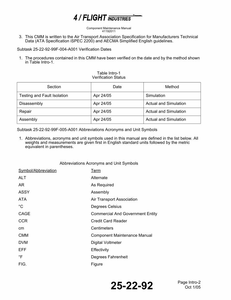
3. This CMM is written to the Air Transport Association Specification for Manufacturers Technical
Data (ATA Specification iSPEC 2200) and AECMA Simplified English guidelines.
Subtask 25-22-92-99F-004-A001 Verification Dates 4
1. The procedures contained in this CMM have been verified on the date and by the method shown in Table Intro-1.
Table Intro-1Verification Status
Subtask 25-22-92-99F-005-A001 Abbreviations Acronyms and Unit Symbols 5
1. Abbreviations, acronyms and unit symbols used in this manual are defined in the list below. All weights and measurements are given first in English standard units followed by the metric equivalent in parentheses.
Section Date Method
Testing and Fault Isolation Apr 24/05 Simulation
Disassembly Apr 24/05 Actual and Simulation
Repair Apr 24/05 Actual and Simulation
Assembly Apr 24/05 Actual and Simulation
Abbreviations Acronyms and Unit Symbols
Symbol/Abbreviation Term
ALT Alternate
AR As Required
ASSY Assembly
ATA Air Transport Association
°C Degrees Celsius
CAGE Commercial And Government Entity
CCR Credit Card Reader
cm Centimeters
CMM Component Maintenance Manual
DVM Digital Voltmeter
EFF Effectivity
°F Degrees Fahrenheit
FIG. Figure

25-22-92 Page Intro-3Oct 1/05
Component Maintenance Manual41192011
FWD Forward
IFE In-Flight Entertainment
IPL Illustrated Parts List
kg Kilograms
lbs Pounds
NHA Next Higher Assembly
NO. Number
NP Non Procurable
PCU Passenger Control Unit
PN Part Number
REPLD Replaced
REPLS Replaces
REV Revision
RF Reference
SB Service Bulletin
SEB Seat Electronics Box
SUPSD Superseded
SUPSDS Supersedes
V Vendor
VDU Video Display Unit
Abbreviations Acronyms and Unit Symbols
Symbol/Abbreviation Term

25-22-92 Page Intro-4Oct 1/05
Component Maintenance Manual41192011
THIS PAGE IS INTENTIONALLY LEFT BLANK

25-22-92 Page 1Oct 1/05
Description and Operation
Component Maintenance Manual41192011
DESCRIPTION AND OPERATION
00
TASK 25-22-92-870-801-A DESCRIPTION
Subtask 25-22-92-870-001-A001 Physical Description 1
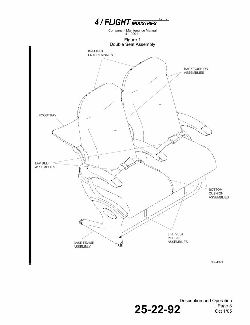
1. The seat assembly is shown in Figure 1. The seat assembly is mounted to the seat tracks with track fittings and front stud assemblies. The seats are equipped with a base frame assembly, back structure assemblies, armrest assemblies, foodtray assemblies, lap belts, literature pockets, bottom cushions, back cushions, and an in-flight entertainment (IFE) system. Several lap belt extensions are supplied for each aircraft shipset. The hydraulic locks control the recline positions and are factory set for the upright and full recline limits. The recline control buttons are located on both the outboard and aisle armrest assemblies. The recline position can be adjusted by the passenger within the range of travel set at the factory.
2. The base frame assembly provides installation of the back structure assemblies, armrest assemblies, and foodtray assemblies. The base frame assembly is equipped with the baggage bar assembly, the track fittings, the front stud assemblies, the inboard leg, the adjustable foodtray stop assemblies, spreader assemblies, the diaphragms, and the tube assemblies.
3. The back structure assembly is constructed of composite materials for strength and light weight. Velcro is bonded to the structure to secure the back cushion and the literature pocket. The latch shroud assemblies are provided to secure the foodtray assemblies in the stowed position. The EAS quadrant assembly is mounted to the bottom corner of the back structure assembly and is used to attach the hydraulic lock.
4. The center armrest assembly structure is constructed of molded and bonded plastic, painted to match the seat exterior.
5. The aisle and outboard armrest assemblies are constructed of molded and bonded plastic, painted to match the airline requirements. A spring-loaded catch is provided to secure the aisle armrest assembly in the lowered position. The catch is accessible through a cavity on the underside of the structure not visible to the passenger. This feature allows the flight attendant to raise the armcap when necessary.
6. The foodtray assemblies are secured to the base frame assembly with the back structure assembly attachment hardware. The foodtray assemblies are secured in the stowed position with the latch shroud assembly. A setscrew is used to adjust the foodtray assembly to a 2.0 degree rise above horizontal in the deployed position. The 2.0 degree rise levels the foodtray during flight. The 41192011-101, 102, -105, -106, -107, and -108 seat assemblies contain a foodtray assembly; the 41192011-103 and -104 seat assemblies contain a sliding foodtray assembly.
7. The bottom cushions, back cushions, and literature pockets are attached to the seat with Velcro and mechanical snaps. The cushion cover color and material are provided to meet the specifications of the airline.
8. The seats are equipped with provisions for installing an in-flight entertainment (IFE) system. Cables and mounting provisions are provided for IFE components such as a AC Outlet Unit and SVDUs.

25-22-92 Page 2Oct 1/05
Description and Operation
Component Maintenance Manual41192011
TASK 25-22-92-870-802-A OPERATION
Subtask 25-22-92-870-002-A001 Operation 2
1. To recline the seat, push the recline button on the armrest assembly and lean back in the seat. To move the seat to the full upright position, lean forward in the seat and push the recline button. The seat will move forward when the recline button is pushed.
2. To lower the foodtray assembly, hold the foodtray, turn the foodtray latch assembly, and lower the foodtray completely. To replace the foodtray assembly, raise the foodtray completely, and turn the foodtray latch assembly to lock the foodtray in place.
3. To raise the armrest assembly, push the catch located under the armrest structure, and lift the armrest. The catch is spring-loaded and will lock the armrest when lowered.
TASK 25-22-92-870-803-A LEADING PARTICULARS
Subtask 25-22-92-870-003-A001 Leading Particulars 3
1. The leading particulars for the seat assemblies are given in Table 1.
Table 1Leading Particulars
Figure 1
Property Specifications
Manufacturer 4/Flight Industries (V34696)
Nomenclature Double Seat Assembly
Part Numbers 41192011-101 thru -108
Seat Back Angle - Upright 11.0 degrees from vertical
Seat Back Angle - Recline 14.0 degrees from upright
Foodtable Angle 2.0 degrees raised from horizontal
Dimensions:
Width 42.5 inches (108,0 cm)
Height 46.9 inches (111,3 cm)
Depth (upright position) 25.3 inches (64,3 cm); 28.0 inches (71,1 cm) with seat reclined
25-22-92 Page 3Oct 1/05
Description and Operation
Component Maintenance Manual41192011
Figure 1
Double Seat Assembly
38943-9
IN-FLIGHTENTERTAINMENT
FOODTRAY
BASE FRAMEASSEMBLY
LAP BELTASSEMBLIES
BACK CUSHIONASSEMBLIES
BOTTOMCUSHIONASSEMBLIES
LIFE VESTPOUCHASSEMBLIES

25-22-92 Page 4Oct 1/05
Description and Operation
Component Maintenance Manual41192011
THIS PAGE IS INTENTIONALLY LEFT BLANK

25-22-92 Page 1001Oct 1/05
Testing and Fault Isolation
Component Maintenance Manual41192011
TESTING AND FAULT ISOLATION
10001000
TASK 25-22-92-700-801-A GENERAL TESTING INFORMATION
Subtask 25-22-92-700-001-A001 General Information 1
1. This section contains testing and fault isolation procedures. The tests can be done on or off the aircraft.
2. If a failure occurs during a test, refer to fault isolation procedures to identify the trouble, possible cause, and corrective action.
3. No special tools or fixtures are needed to test the seat assembly.
4. The testing and fault isolation procedures should be conducted a minimum of once yearly.
5. Flotation cushions must be checked every 3 years after manufacturing date.
TASK 25-22-92-940-811-A MATERIALS AND TEST EQUIPMENT
Subtask 25-22-92-700-002-A001 Consumable Materials 2
1. No consumable materials are needed for these testing and fault Isolation procedures.
Subtask 25-22-92-94B-011-A001 Test Equipment 3
1. Test equipment needed for testing are listed in Table 1001
NOTE: Equivalent substitutes may be used for the items specified.
Table 1001Test Equipment
TASK 25-22-92-700-802-A TESTING PROCEDURES
Subtask 25-22-92-700-003-A001 Foodtray Test 4
1. Hold foodtray assembly and turn foodtray latch assembly. Move foodtray assembly to the deployed position.
A. Foodtray latch assembly must turn freely without binding.
B. Foodtray assembly must pivot on foodtray arms freely without binding.
C. Foodtray angle must be raised 2.0 degrees from horizontal measured from bottom of inboard seat leg when in the deployed position.
Tool Number and Tool Name Source Use
, Voltmeter, Digital Commercially available To perform IFE continuity checks.
25-22-92 Page 1002Oct 1/05
Testing and Fault Isolation
Component Maintenance Manual41192011
2. Lift foodtray assembly up to the stowed position and secure with foodtray latch assembly.
A. Foodtray latch assembly must hold foodtray assembly securely in the stowed position.
B. Foodtray assembly must rest flat against seat back assembly. There must be no play between foodtray assembly and foodtray arm assemblies.
Subtask 25-22-92-700-004-A001 Lap Belt Assembly Test 5
1. Fit belt clip in the belt catch.
A. Belt catch must lock positively.
2. With a quick jolt, pull on lap belts to ensure that lap belt does not slip through belt catch.
A. Belt catch must lock belt.
3. Lift belt release and separate belt clip from belt catch.
A. Belt catch must unlock and release belt clip without difficulty.
Subtask 25-22-92-700-005-A001 Seat Recline Test 6
1. Press recline button, then move seat back assembly through the entire recline travel range.
A. Motion must be free and without binding.
2. From the recline position, press and hold recline button and allow seat back assembly to rise to the full upright position.
A. Seat back assembly must move freely to full upright position.
B. Hydraulic lock and recline cable must not bind.
3. From the full upright position, press and hold recline button and move the seat back assembly to the full recline position and release recline button.
A. Seat back assembly must move smoothly and positively into full recline position.
B. Seat back assembly must remain securely locked in full recline position.
NOTE: Full recline must be 14.0 degrees from upright.
4. From the full recline position, press and hold recline button and move seat back assembly to the full upright position and release recline button.
A. Seat back assembly must move smoothly and positively into full upright position.
B. Seat back assembly must remain securely locked in full upright position.
NOTE: Full upright position must be 11.0 degrees from vertical.
5. Press and hold recline button and move seat back assembly to a mid-point in the recline travel and release recline button.

25-22-92 Page 1003Oct 1/05
Testing and Fault Isolation
Component Maintenance Manual41192011
6. Push on seat back assembly to check that seat back is locked in the desired position.
A. Seat back assembly must remain securely locked in the selected recline position.
Subtask 25-22-92-700-006-A001 Recline Armrest Pivot Test 7
1. Push up on catch located on underside of armrest (hidden from passenger view) and lift armrest.
A. Catch must pivot against a slight spring resistance and release recline armrest assembly.
B. Recline armrest assembly must pivot upright without binding.
2. Lower armrest completely.
3. Lift armrest slightly to check for secure engagement with base frame assembly.
A. Catch must lock armrest in the lowered position.
Subtask 25-22-92-700-008-A001 Bottom Cushion Flotation Test 8
NOTE: This test is only applicable to seat assemblies equipped with bottom flotation cushions.
1. Randomly select one flotation cushion from cushions with oldest manufacturing dates and perform a buoyancy test of flotation cushion per TSO-C72c.
2. Flotation cushion must meet a minimum buoyancy force of 14 lbs (6,35 kg).
Subtask 25-22-92-700-009-A001 IFE Cable Continuity Checks 9
1. If the in-flight entertainment (IFE) system is not operating properly, use a digital voltmeter (DVM) to perform continuity checks on the following cables (IPL Figure 4):
A. VDU to VDU jumper cable (40).
B. IFE cable (55).
C. Audio cable (60).
2. Use the IFE wiring diagram in Figure 2001 to check the continuity of each wire in these cables.
TASK 25-22-92-700-803-A FAULT ISOLATION PROCEDURES
Subtask 25-22-92-810-001-A001 Fault Isolation 10
1. Fault isolation procedures are given in Table 1002.

25-22-92 Page 1004Oct 1/05
Testing and Fault Isolation
Component Maintenance Manual41192011
Table 1002
Fault Isolation Procedures
Trouble Probable Cause Corrective Action
Foodtray latch assembly (5, IPL Figure 2) binds or does not hold foodtray assembly (145, IPL Figure 1) stowed in position securely.
Bent or broken foodtray latch assembly (5, IPL Figure 2).
Replace foodtray latch assembly.
Bent foodtray arms (160, 165, 170, or 175, IPL Figure 7).
Replace foodtray arm assembly.
Foodtray does not pivot freely on foodtray arms.
Bent foodtray arms (160, 165, 170, or 175).
Replace foodtray arm assembly.
Foodtray assembly angle is not 2.0 degrees above horizontal.
Foodtray stop assembly (255 or 260, IPL Figure 10) requires adjustment.
Refer to ASSEMBLY to adjust foodtray stop assembly.
Lap belt catch does not lock on belt when pulled quickly.
Damaged lap belt assemblies (115, IPL Figure 1) mechanism.
Replace lap belt assembly.
Seat back assembly binds along recline travel or does not recline.
Damaged hydraulic lock (45, IPL Figure 7).
Replace hydraulic lock.
Recline cable assembly (40, IPL Figure 9) not properly connected to hydraulic lock.
Replace recline cable assembly.
Damaged recline cable assembly (40).
Replace recline cable assembly.
Back assembly (95 or 100, IPL Figure 7) movement is obstructed by a foreign object.
Remove obstruction.
Seat back assembly does not lock in desired position.
Damaged recline cable assembly (40, IPL Figure 9).
Replace recline cable assembly.
Damaged hydraulic lock (45, IPL Figure 7).
Replace hydraulic lock.
Seat back assembly is not set to correct full recline or full upright settings.
Hydraulic lock (45) requires adjustment.
Refer to ASSEMBLY to adjust seat back assembly full recline and full upright settings.
Armrest binds when pivoted to upright position.
Bent or damaged armrest assembly (235, 280, or 300).
Replace armrest assembly.
Flotation cushion does not meet minimum buoyancy force of 14 lbs (6,35 kg).
Loss of buoyancy force in upholstered bottom cushion assembly (15, IPL Figure 1).
Replace flotation cushion.
Continuity not present in IFE cables.
Defective cable. Replace cable.

25-22-92 Page 2001Oct 1/05
Schematics And Wiring Diagrams
Component Maintenance Manual41192011
SCHEMATICS AND WIRING DIAGRAMS
20002000
TASK 25-22-92-99F-821-A GENERAL INFORMATION
Subtask 25-22-92-99F-021-A01 General Information 1
1. This section has the schematic and wiring diagram illustrations necessary to describe the Double Seat Assembly.
TASK 25-22-92-99F-822-A OPERATIONAL SCHEMATIC
Subtask 25-22-92-99F-022-A01 Schematics 2
1. The seat assembly wiring diagram is shown in Figure 2001.Figure 2001

25-22-92 Page 2002Oct 1/05
Schematics And Wiring Diagrams
Component Maintenance Manual41192011
Figure 2001
IFE Wiring Diagram

25-22-92 Page 3001Oct 1/05
Disassembly
Component Maintenance Manual41192011
DISASSEMBLY
30003000
TASK 25-22-92-000-801-A GENERAL DISASSEMBLY INFORMATION
Subtask 25-22-92-000-001-A001 General Information 1
1. This section contains instructions to disassemble the seat assembly.
2. To use this section, first refer to TESTING AND FAULT ISOLATION and INSPECTION/CHECK to identify the damaged and worn parts. Disassemble the unit only as far as necessary to remove the damaged components.
3. Refer to REPAIR to replace stripped Helicoil inserts, repair damaged dress covers, and replace bonded caps and Velcro.
4. No special tools or fixtures are needed to disassemble the seat assembly.
NOTE: When removing fasteners (bolts, screws, washers, nuts, etc.), bag and tag parts for ease of assembly.
TASK 25-22-92-940-802-A MATERIALS AND TOOLS
Subtask 25-22-92-94A-002-A001 Consumable Materials 2
1. No consumable materials are needed for these disassembly procedures.
Subtask 25-22-92-94B-003-A001 Special Tools 3
1. No special tools are needed for these disassembly procedures.
TASK 25-22-92-000-003-A DISASSEMBLY PROCEDURES
Subtask 25-22-92-000-004-A001 Seat Assembly Disassembly 4
CAUTION: EACH SEAT ASSEMBLY HAS COVERS THAT ARE EASILY DAMAGED. COVER THE SURFACES AND HANDLE THE UNIT WITH CARE TO PREVENT DAMAGE.
1. Disassemble double seat assembly as follows (IPL Figure 1):
A. Remove and disassemble seat cushions as follows:
(1) Remove bottom cushion assemblies (15) from double seat structure assembly (170).
(2) Separate upholstery covers (20) from fireblocked bottom cushions (25).
(3) Remove back cushion assemblies (30) from double seat structure assembly (170).
(4) Separate back upholstery covers (35) from back fireblocked cushions (40 and 55).
B. Remove literature pocket assemblies (60) from double seat structure assembly (170) by removing screws (70), washers (75), and literature pocket springs (65).

25-22-92 Page 3002Oct 1/05
Disassembly
Component Maintenance Manual41192011
C. Remove life vest pouches (80) from double seat structure assembly (170) by removing nuts (85), washers (90 and 95), and screws (100).
D. For 41192011-107 and -108 configurations only: Remove wedge assembly (105).
E. Disconnect lap belt assemblies (115) from seat belt studs (250, IPL Figure 10).
F. Remove monitor shroud assembly (125, IPL Figure 1) by removing screws (130).
G. Remove and disassemble rear shroud assemblies (125) from back assemblies as follows (IPL Figure 2):
(1) Remove latch stops (25 and 26) by removing screws (40) and washers (45).
(2) Remove foodtray latch assembly (5) from monitor shrouds (70) by removing cotter pins (10), washers (15), compression springs (20), and nylon washers (21).
(3) For 41191274-503 and -504 configurations only: Remove latch stops (27) by removing screws (40) and washers (45).
(4) Remove monitor attachment shrouds (50) by removing screws (55).
(5) Remove USB coupler (60) by removing screws (65).
H. Disassemble IFE provisions installation as follows (IPL Figure 3):
(1) Remove monitor bracket assemblies (10) by removing screws (20) and nylon washers (25).
(2) Remove dummy monitors (35) by removing screws (40).
(3) Remove monitor bezels (5) from dummy monitors (35) by removing screws (6).
(4) Remove interface bracket cover (55) by removing bolts (60) and washers (65).
I. Remove shroud attachments (195, IPL Figure 7) by removing screws (200) and washers (205).
J. Remove back plate assemblies (210) by removing screws (215) and washers (220).
K. Disassemble back cushion as follows (IPL Figure 1):
(1) Remove fireblocked headrest cushion assembly (55) from back assemblies (95 and 100, IPL Figure 7) and upholstery back cover assembly (50, IPL Figure 1) from double seat structure assembly (170).
L. Disassemble wiring harness installation as follows (IPL Figure 4):
(1) Remove cable ties (10 and 15) securing cable assemblies (40, 55 and 60) to structure assembly.
(2) Remove cable clamps (20) from structure assembly by removing screws (25).
(3) Remove cable assemblies (40, 55 and 60) from structure assembly.

25-22-92 Page 3003Oct 1/05
Disassembly
Component Maintenance Manual41192011
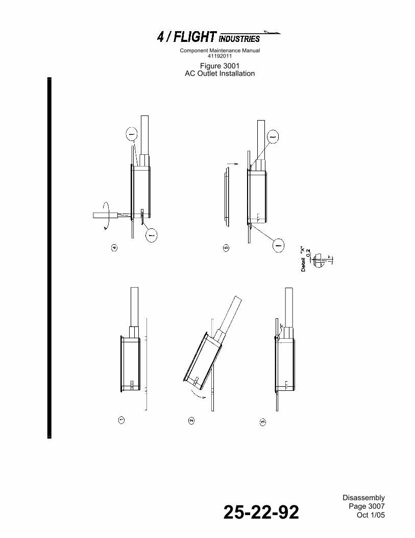
M. For 41194011-101 thru -108 configurations only: Loosen screws on AC outlet unit (10, IPL Figure 1A) and remove it from base frame assembly (320, IPL Figure 7) as shown in Figure 3001.
N. For 41194011-111 thru -118 configurations only:
(1) Remove USB couplers (15, IPL Figure 1A) and USB cable (25) by removing screws (20).
(2) Remove SVDUs (30) by removing screws (35).
O. Remove and disassemble PC power port installation as follows (IPL Figure 5A):
(1) Remove cover assembly (20) by removing screws (25) and washers (30).
(2) Remove fwd strap assembly (35) and bracket assembly (50) by removing screws (40) and washers (45).
(3) Remove stabilizer (55) by removing screws (60 and 70) and washers (65 and 75).
(4) Remove clamp assembly (5) and clamp (15) by removing screw (10).
P. Remove foodtray assemblies (145, IPL Figure 1) from foodtray arm assemblies (160, 165, 170, and 175, IPL Figure 7) by removing screws (150, IPL Figure 1), washers (155), and torsion tubes (165).
Q. Disassemble sliding foodtray assembly (IPL Figure 6):
(1) Remove crosstube (5) and foodtable stop assemblies (15) from foodtable assembly (30) by removing screws (10).
(2) Remove pivot pins (20) and studs (25) from foodtable stop assemblies (15).
R. Disassemble structure assembly as follows (IPL Figure 7):
(1) Remove upper cart bumper (5) from base frame assembly (320) by removing screws (10) and washers (15).
(2) Remove lower cart bumper (20) from base frame assembly (320) by removing cap screw (25), screws (30) and washers (35).
(3) Remove hydraulic locks (45) from back assemblies (95 and 100) as follows:
(a) Remove cable ties (40 and 85) securing recline cable assembly (40, IPL Figure 9) to hydraulic locks (45, IPL Figure 7).
(b) Disconnect hydraulic lock clip at recline cable assembly (40, IPL Figure 9) from hydraulic locks (45, IPL Figure 7).

25-22-92 Page 3004Oct 1/05
Disassembly
Component Maintenance Manual41192011
WARNING: DISCONNECTING HYDRAULIC LOCKS (45) FROM EAS QUADRANT ASSEMBLIES (5, IPL FIGURE 8) WILL ALLOW BACK STRUCTURE ASSEMBLIES TO FALL FREE. USE CARE TO PREVENT INJURY TO PERSONNEL OR DAMAGE TO PARTS.
(c) Disconnect hydraulic locks (45, IPL Figure 7) from EAS quadrants (5, IPL Figure 8) by removing nuts (50, IPL Figure 7), washers (55), and bolts (60).
(d) Remove hydraulic locks (45) from recline trunnion pins (65 and 70) by removing nuts (75) and washers (80).
(4) Remove front back plates (180) from back assemblies (95 and 100) by removing screws (185) and washers (190).
(5) Remove shroud attachments (195) by removing screws (200) and washers (205).
(6) Remove back plate assemblies (210) by removing screws (215) and washers (220).
(7) Remove cable clamps (225) by removing screws (230).
(8) Remove foodtray arms (160, 165, 170, and 175) and back assemblies (95 and 100) from base frame assembly (320).
(9) Remove back structure assemblies (95 and 100) from base frame assembly (320) by removing bolts (105 and 110), washers (115 and 120), spacers (125), nuts (135), washers (140), spacers (145), and back pivot pin (155). For 41191270-505 and -506 configurations only: Remove straps (130 and 150).
(10) Disassemble back assemblies (95 and 100) as follows (IPL Figure 8):
(a) Remove EAS quadrant assemblies (5) from back structure assemblies (120) by removing bolts (10), plugs (15) and bushings (20) from back fitting pivot assemblies (25).
(11) Remove armrest assembly (235, IPL Figure 7) from base frame assembly (320) by removing retaining rings (240), wave washers (245), and pins (250).
(12) Remove plunger module (255) from aisle spreader assembly (425, IPL Figure 10) by removing screw (260, IPL Figure 7).
(13) Remove plunger (265) and spring (275) from plunger module (255) by removing setscrew (270).
(14) Remove armrest assembly (280) from base frame assembly (320) by removing retaining ring (285), wave washers (290) and pin (295).
(15) Remove center armrest assembly (300) from base frame assembly (320) by removing retaining ring (305), washers (310), and pin (315).
(16) Remove recline cable assembly (40, IPL Figure 9) from aisle and outboard armrest assemblies (235 and 280, IPL Figure 7) and base frame assembly (320) as follows:
(a) Disconnect escutcheon (50, IPL Figure 9) and wave spring washer (55) of recline cable assembly (40) from armrest structure assembly (80) by pressing push tabs, on each side of escutcheon, at the same time.
25-22-92 Page 3005Oct 1/05
Disassembly
Component Maintenance Manual41192011
(17) Disassemble armrest assemblies (235, 280 and 300, IPL Figure 7) as follows:
CAUTION: BE CAREFUL WHEN REMOVING ARMCAP ASSEMBLY (5, IPL FIGURE 9) SO AS NOT TO BEND OR DAMAGE ITS BRACKET.
(a) Remove armcap assembly (5) from armrest structure assembly (80) as follows:
1) Remove screw (10).
2) Insert an Allen wrench through cutout in armrest structure assembly (Figure 3002) and loosen captive screw.
3) Carefully lift out armcap assembly to disengage its bracket from the armrest structure assembly without bending or damaging its bracket.
(b) Remove escutcheon (15, IPL Figure 9) from armrest structure assembly (80) by removing screws (20) and washers (25).
S. Disassemble base frame assembly (320, IPL Figure 7) as follows (IPL Figure 10):
(1) On P/Ns 41191205-507 and -508 units only, remove and disassemble baggage bar assembly (5) as follows:
(a) Remove baggage bar A-frame assembly (98) by removing one nut (325), two washers (330), one bolt (340), one nut (350), two washers (355) and one bolt (360).
(b) Remove knob (50) and latch assembly (60) from baggage bar assembly (75) by removing screw (55).
(c) Remove baggage bar assembly (75) from baggage bar A-frame assembly (98) by removing nuts (80), washers (90) and bolts (95).
(d) Remove plug (70) from baggage bar assembly (75) by removing spring pin (65).
(2) On P/Ns 41191205-513 through -516 units only, remove and disassemble baggage bar assembly (5F and 5G) as follows:
(a) Remove baggage bar assembly (5F and 5G) by removing screws (10 and 15) and washers (20).
(b) Remove plug assembly (40) from tube (45).
(c) Disconnect tubes (30 and 45) by removing spring pin (25).
(d) Remove plug (35).
(3) On P/Ns 41191205-507 and -508 units only, remove and disassemble spring latch assembly (105) as follows:
(a) Remove end cap (110), spring (120), and latch pin assembly (125) from leg (420) by removing screws (115).
(b) Remove guide (130) from leg (420) by removing nuts (135), washers (140), and screws (145).
25-22-92 Page 3006Oct 1/05
Disassembly
Component Maintenance Manual41192011
(4) On P/Ns 41191205-513 through -516 units only, remove bracket assemblies (150) by removing screws (160) and washers (165).
(5) Remove rear track fittings (175) from leg (420) and fwd outboard adapter (230) by removing cap nuts (180), washers (185, 190, and 195), bolts (200 and 205), and grommets (210).
(6) Remove front stud assemblies (215) and trunnions (220 and 225) from leg (420) and fwd outboard adapter (230).
(7) Remove strap assemblies (235) from front tube assembly (320) by removing screws (240) and washers (245).
(8) Remove aisle spreader assembly (425) and leg (420) from front and rear tube assemblies (320 and 345) by removing one nut (325), two washers (330), one bolt (335), one nut (350), two washers (355), and one bolt (365).
(9) Remove outboard spreader assembly (430) and fwd outboard adapter (230) from front and rear tube assemblies (320 and 345) by removing one nut (325), two washers (330), one bolt (340), one nut (330), two washers (355), and one bolt (365).
(10) Remove slip plugs (370) from aft tube (395) by removing cap nuts (375), washers (380 and 385), and screws (390 and 400).
Figure 3001
25-22-92 Page 3007Oct 1/05
Disassembly
Component Maintenance Manual41192011
Figure 3001 AC Outlet Installation
Figure 3002

25-22-92 Page 3008Oct 1/05
Disassembly
Component Maintenance Manual41192011
Figure 3002 Armrest Structure Assembly

25-22-92 Page 4001Oct 1/05
Cleaning
Component Maintenance Manual41192011
CLEANING
40004000
TASK 25-22-92-100-801-A GENERAL INFORMATION FOR CLEANING
Subtask 25-22-92-100-001-A001 General Information 1
CAUTION: THE DECORATIVE LAMINATE SURFACE OF VARIOUS INTERIOR COMPONENTS CAN BE DAMAGED BY THE USE OF INCORRECT CLEANING MATERIALS AND EQUIPMENT, OR INCORRECT MIXING OF THE SPECIFIED CLEANING MATERIALS.
CAUTION: DO NOT USE ABRASIVE MATERIALS ON THE DECORATIVE SURFACES. DO NOT SCRAPE THE SURFACES WITH SHARP TOOLS.
1. This section provides cleaning instructions for the seat assemblies. Correct use of the materials and equipment will provide acceptable cleaning, minimize hazards to personnel, and prevent possible damage to the equipment.
NOTE: The companies that make the cleaning materials can change the formula. Therefore, always follow the instructions given on the container. The instructions to mix and use the cleaning materials, given on or provided with the container, supersede the instructions given here.
TASK 25-22-92-100-802-A SAFETY PRECAUTIONS
Subtask 25-22-92-100-002-A001 Safety Precautions 2
WARNING: ALIPHATIC NAPHTHA IS TOXIC AND FLAMMABLE. PREVENT CONTACT WITH EYES AND SKIN, AND DO NOT BREATHE THE VAPORS. KEEP AWAY FROM HEAT AND OPEN FLAME. USE IN A WELL VENTILATED AREA. DO NOT TAKE INTERNALLY.
WARNING: BRULIN 815MX CONTAINS 2-AMINOETHANOL. DIRECT CONTACT CAN CAUSE EYE IRRITATION. LONG CONTACT CAN CAUSE SKIN IRRITATION. WEAR RUBBER GLOVES, AN APRON, AND GOGGLES.
1. All cleaning materials have some hazard related to the use. Follow the safety warnings given to make sure personnel are safe and to prevent damage to the equipment.
TASK 25-22-92-940-841-A MATERIALS AND SPECIAL TOOLS
Subtask 25-22-92-94A-041-A001 Consumable Materials 3
1. Consumable materials needed for cleaning are given in Table 4001.
NOTE: Equivalent substitutes may be used for the items listed.

25-22-92 Page 4002Oct 1/05
Cleaning
Component Maintenance Manual41192011
Table 4001
Consumable Materials
Material Name and Number Source (1) Use
CALLA 301-A LEMON, Detergent, Aqueous Anionic
Zip-Chem Prod., Inc. (V8E913) To clean molded plastic areas, clean metal parts, and remove adhesive.
-, Cleaner, Foam Dupont E. I. De Nemours Co., Inc. (V2H935)
To clean fabric.
-, Cleaner, Glamorene Glamorene Products Corp.(V21440)
To clean fabric.
-, Cleaner, Mystic Foam Mystic Foam Corp. (S00001) To clean fabric.
-, Cleaner, Duo-Dellay Duo-Dellay Products Co. (S00002)
To clean fabric.
-, Cloths, Cotton (clean and dry)
Commercially available To apply prepared detergent solutions.
-, Detergent, Mild Household Commercially available To clean molded plastic areas.
-, Fluid, Carbone Cleaning Carbone Corp. (S00003) To clean fabric.
MIL-PRF-680, Type III, Solvent, Degreasing (optional)
Commercially available To clean metal parts.
-, Solvent, Cleaning (Aliphatic Naphtha) (2)
Commercially available To clean metal parts.
-, Solvent, Cleaning Agent, Dupont Dry Cleaner
Dupont E. I. De Nemours Co., Inc. (V2H935)
To clean fabric.
-, Solvent, Impregnated Powder, Powder-ene
Von Schrader Co. (V23738) To clean fabric.
#0166, Lubricant, Silicone Zep Manufacturing Co.(V27674)
To clean metal parts.
815MX, Detergent, Aqueous Anionic
Brulin & Co. (V94058) To clean molded plastic areas, clean metal parts, and remove adhesive.
(1) Refer to IPL INTRODUCTION for vendor information.(2) Alternate materials. Cleaning solvent shall be used only in well-ventilated areas. Detergents Nos. 815MX and 301-A are for use in areas that are not well-ventilated or where use of petroleum-based materials is not allowed or is inadvisable.

25-22-92 Page 4003Oct 1/05
Cleaning
Component Maintenance Manual41192011
Subtask 25-22-92-94B-041-A001 Special Tools 4
1. Special tools needed for Cleaning are given in Table 4002.
NOTE: Equivalent substitutes may be used for the items listed.
Table 4002Special Tools
TASK 25-22-92-100-803-A CLEANING PROCEDURES
Subtask 25-22-92-100-004-A001 Molded Plastic Cleaning 5
1. Use of Household Detergent
A. Prepare a solution of mild household detergent and lukewarm water (approximately 1 part detergent to 50 parts water). Apply the mild detergent solution with a sponge or a cotton cloth. Scrub soiled areas and repeat the applications as required to remove all dirt. Use a soft-bristled brush to clean heavily textured surfaces or crevices. Rinse the surfaces with clean water to remove the detergent solution. Dry the surfaces with a clean, dry, cotton cloth.
2. Use of BRULIN 815MX
CAUTION: DO NOT USE BRULIN 815MX CLEANER UNDILUTED. SOLUTIONS STRONGER THAN SPECIFIED CAN DAMAGE THE DECORATIVE SURFACES.
A. Prepare a solution of 1 part BRULIN 815MX to 64 parts water for light soil and up to one part BRULIN 815MX to 10 parts water for heavy soil.
B. Apply the solution with a spray bottle, a soft-bristled brush, or a cotton cloth.
C. Scrub soiled areas with a soft-bristled brush or a cotton cloth and repeat the applications as required to remove any dirt. Wipe the solution off with a clean, damp, cotton cloth.
D. Dry the surfaces with a clean, dry, cotton cloth.
Tool Number and Name Source Use
-, Apron Commercially available To protect the body when using solvents and detergents.
-, Bottle, Spray Commercially available To apply prepared detergent solutions.
-, Brush, Soft-Bristled Commercially available To apply prepared detergent solutions.
-, Gloves, Chemical Resistant Commercially available To protect the hands when using cleaning solvents.
-, Goggles, Eye Safety Commercially available To protect the eyes when using cleaning solvents.
-, Vacuum Commercially available To clean fabric.
25-22-92 Page 4004Oct 1/05
Cleaning
Component Maintenance Manual41192011
3. Use of CALLA 301-A LEMON
A. Prepare a solution of one part CALLA 301-A LEMON with four to eight parts water for general cleaning.
B. Use full strength on spots. Apply the solution with a spray bottle, a soft-bristled brush, or a cotton cloth.
C. Allow time for the solution to penetrate.
D. Scrub soiled areas with a soft-bristled brush or cotton cloth and repeat the applications as required to remove all dirt.
E. Wipe the solution off with a clean, damp, cotton cloth. Dry the surfaces with a clean, dry, cotton cloth.
Subtask 25-22-92-100-005-A001 Metal Part Cleaning 6
1. As a normal routine for cleaning and maintenance, all metal parts in contact with one another must be lubricated with silicone lubricant during any shop repair or at least once every 2 years.
2. Use of Solvent or Aliphatic Naphtha
WARNING: ALIPHATIC NAPHTHA IS TOXIC AND FLAMMABLE. USE ONLY IN WELL VENTILATED AREA AND AWAY FROM OPEN FLAME. AVOID PROLONGED OR REPEATED CONTACT WITH SKIN OR INHALATION OF VAPORS. USE SHOP SAFETY PRECAUTION FOR HANDLING FLAMMABLE MATERIALS.
CAUTION: DO NOT LET THE ALIPHATIC NAPHTHA CONTACT THE DECOR MATERIAL OR PLASTIC COMPONENTS. THE NAPHTHA CAN DAMAGE THE COMPONENTS AND MATERIALS.
A. Moisten a clean, dry, cotton cloth with cleaning solvent or Aliphatic Naphtha and wipe the metal parts clean.
B. Repeat the applications as required to remove all dirt. Dry the parts with a clean, dry, cotton cloth before solvent evaporates.
3. Use of BRULIN 815MX
A. Prepare a solution of one part BRULIN 815MX to 64 parts water for light soil and up to one part BRULIN 815MX to 10 parts water for heavy soil.
B. Apply the solution with a spray bottle, a soft-bristled brush, or a cotton cloth.
C. Scrub soiled areas with a soft-bristled brush or a cotton cloth.
D. Repeat the applications as required to remove all dirt. Wipe the solution off with a clean, damp, cotton cloth.
E. Dry the part with a clean, dry, cotton cloth.

25-22-92 Page 4005Oct 1/05
Cleaning
Component Maintenance Manual41192011
4. Use of CALLA 301-A LEMON
A. Prepare a solution of one part CALLA 301-A LEMON with four to eight parts water for general cleaning.
B. Use full strength for heavy soil and adhesives.
C. Apply the solution with either a spray bottle, a soft-bristled brush, or a cotton cloth.
D. Allow time for the solution to penetrate.
E. Scrub soiled areas with a soft-bristled brush or a cotton cloth.
F. Repeat the applications as required to remove all dirt.
G. Wipe the solution off with a clean, damp, cotton cloth.
H. Dry the part with a clean, dry, cotton cloth.
Subtask 25-22-92-100-006-A001 Adhesive Removal Procedures 7
1. Use of BRULIN 815MX
A. Prepare a solution of one part BRULIN 815MX to ten parts water to remove adhesive tape or adhesive residue.
B. Moisten a clean cotton cloth with the solution and wipe the area clean.
C. Repeat the applications as required to remove all residue.
D. Wipe the solution off with a clean, damp, cotton cloth.
E. Dry the surface with a clean, dry, cotton cloth.
2. Use of CALLA 301-A LEMON
A. Use CALLA 301-A LEMON at full strength to remove adhesive tape or adhesive residue.
B. Apply the solution with a spray bottle, a soft-bristled brush, or a cotton cloth.
C. Allow time for the solution to penetrate.
D. Scrub soiled areas with a soft-bristled brush or a cotton cloth.
E. Repeat the applications as required to remove all dirt.
F. Wipe the solution off with a clean, damp, cotton cloth. Dry the surface with a clean, dry, cotton cloth.

25-22-92 Page 4006Oct 1/05
Cleaning
Component Maintenance Manual41192011
Subtask 25-22-92-100-007-A001 Fabric Cleaning 8
CAUTION: DO NOT POUND OR BEAT UPHOLSTERED COVERS AS THIS DOES NOT EFFECTIVELY CLEAN THE UPHOLSTERY AND CAN HASTEN WEAR.
1. The recommended fabric cleaning materials are given in Table 4001.
NOTE: Dry cleaning is the preferred method of cleaning the seat fabric.
A. Vacuum upholstery thoroughly, or brush with a soft-bristle upholstery or clothing brush (Table 4002).
B. Remove dry or water-borne soil with concentrated detergent preparations, commonly called upholstery shampoo. Use recommended detergent preparations as given in Table 4001. Mix upholstery shampoo as directed on container and apply to a small area (approximately one square foot) with a small clean brush. Liberal application will assist in loosening deep-seated dirt.
CAUTION: USE SOLVENT-TYPE CLEANING AGENTS IN WELL-VENTILATED AREA. AVOID BREATHING SOLVENT VAPORS AND PROLONGED SOLVENT CONTACT WITH SKIN. USE SHOP SAFETY PRECAUTIONS FOR HANDLING FLAMMABLE MATERIALS.
C. Oil or grease spots are best removed with solvent-type cleaning agents or with solvent-impregnated powder as given in Table 4001. Test material to be cleaned by first applying cleaning agent to a small area of the material that is not usually visible. Use cleaning agents sparingly, without saturating fabric, to avoid spotting and damage. Apply cleaning agent with a clean, soft cloth, and avoid spreading any stains by working from outer edges toward center of stain.
D. After using upholstery shampoo or solvent-type cleaning agent, roll a clean Turkish towel or other absorbent cloth into a cylindrical shape and wipe off detergent and dirt. Rotate rolled cloth frequently to present a clean section to the fabric surface.
NOTE: Dirt and soil are absorbed or transferred to the clean towel by frequently presenting a clean face to the fabric. Vigorous rubbing may be required to remove soil evenly and to avoid spotting after drying.

25-22-92 Page 5001Oct 1/05
Inspection/Check
Component Maintenance Manual41192011
INSPECTION/CHECK
50005000
TASK 25-22-92-200-801-A GENERAL
Subtask 25-22-92-200-001-A001 General Information 1
1. Refer to the Check Procedures to visually examine the components of the seat assembly for damage and wear.
2. Refer to REPAIR to repair minor damage. If the damage is major or beyond simple repair, replace the part.
3. The inspection/check should be performed a minimum of once annually.
TASK 25-22-92-940-811-A MATERIALS AND TOOLS
Subtask 25-22-92-94A-051-A001 Consumable Materials 2
1. No consumable materials are needed for these inspection/check procedures.
Subtask 25-22-92-94B-051-A001 Special Tools 3
1. No special tools are needed for these inspection/check procedures.
TASK 25-22-92-200-802-A CHECK PROCEDURES
Subtask 25-22-92-200-002-A001 Check Procedures 4
1. Detailed check procedures are given in Table 5001.

25-22-92 Page 5002Oct 1/05
Inspection/Check
Component Maintenance Manual41192011
Table 5001
Check Procedures
Component Method of Inspection Check For Corrective Action
All Parts Visual Cleanliness. Refer to CLEANING to clean parts.
All Metal Parts Visual Nicks, cracks, cuts, scoring, gouges, distortion, corrosion, or other damage which could impair operation.
Repair minor nicks and scratches. Replace damaged parts.
Double Seat Assemblies (IPL Figure 1)
Visual Grease, dirt, frays, or separations on bottom cushion assemblies (15), back cushion assemblies (30 and 45), or literature pocket assemblies (60); cut, torn, or damaged upholstery.
Refer to CLEANING to remove grease and dirt; replace if damaged; refer to REPAIR to repair damaged seams.
Frayed lap belt assemblies (115).
Replace.
IFE Seat Assemblies (IPL Figure 1A)
Visual Bent, deformed or damaged AC outlet unit (10).
Replace.
Cut, frayed, burned or damaged USB cable (25).
Replace.
Cracked or damaged SVDU (30).
Replace.
Monitor Shroud Assembly (IPL Figure 2)
Visual Bent, deformed or damaged foodtray latch assembly (5).
Replace.
IFE Provisions Installation(IPL Figure 3)
Visual Bent, deformed, or damaged monitor bezels (5), monitor bracket assembly (10), or dummy monitors (35).
Replace monitor bezels, monitor pivots, or dummy monitors.
Wiring Harness Installation(IPL Figure 4)
Visual Cut, frayed, burned, or damaged cable assemblies (40, 55, or 60).
Replace.

25-22-92 Page 5003Oct 1/05
Inspection/Check
Component Maintenance Manual41192011
Power Port Installation (IPL Figure 5A)
Visual Bent or damaged clamp assembly (5), cover assembly (20), fwd strap assy (35) or stabilizer (55).
Replace.
Sliding Foodtray Assembly (IPL Figure 6)
Visual Bent or damaged crosstube (5) or pivot pin (20).
Disassemble foodtable pivot assembly and check for bent or damaged crosstube (5) or pivot pin (20). Replace damaged parts.
Structure Assemblies (IPL Figure 7)
Visual Cut, chipped, or damaged cart bumpers (5 and 20); deteriorated rubber.
Replace.
Bent, deformed, or damaged foodtray arm assemblies (160, 165, 170, and 175).
Replace.
Bent, deformed, or damaged hydraulic locks (45); leakage.
Replace.
Back Structure Assemblies (IPL Figure 8)
Visual Loose or missing Velcro (90, 95, 100 and 105).
Refer to REPAIR to replace bonded Velcro.
Cracked or damaged back structure assembly (120).
Replace back structure assembly.
Armrest Assembly (IPL Figures 8A and 9)
Visual Scratched, gouged, or worn armcap assembly (5).
Replace.
Scratched, gouged, or worn escutcheon (15).
Replace.
Cracked or damaged armrest structure assembly (80, or 40, IPL Figure 8A).
Replace.
Base Frame Assemblies (IPL Figure 10)
Visual Bent or damaged baggage bar assembly (5D and 5E or 5F and 5G).
Replace.
Component Method of Inspection Check For Corrective Action

25-22-92 Page 5004Oct 1/05
Inspection/Check
Component Maintenance Manual41192011
Bent or damaged bracket assembly (150).
Replace.
Cracked, damaged or deformed seat belt studs (250).
Replace.
Bent, deformed, or damaged springs (120) or directional studs (270).
Replace springs. Refer to REPAIR to replace directional studs.
Cracked, deformed, or damaged spreader assemblies (425, 430, and 435).
Return base frame assembly to manufacturer for repair.
Loose or missing Velcro (285 and 290).
Refer to REPAIR to replace bonded Velcro.
Component Method of Inspection Check For Corrective Action

25-22-92 Page 6001Oct 1/05
Repair
Component Maintenance Manual41192011
REPAIR
60006000
TASK 25-22-92-300-801-A GENERAL REPAIR INFORMATION
Subtask 25-22-92-300-001-A001 General Information 1
1. This section contains procedures to repair components of the seat assembly. The repair procedures covered in this section are given below.
A. Upholstery Seam Repair
B. Replace Threaded Heilcoil Inserts
C. Replace or Install Bonded Components
D. Touch-up Paint Procedure
E. Repainting Procedure
F. Repair of Minor Nicks or Scratches
TASK 25-22-92-940-801-A MATERIALS AND TOOLS
Subtask 25-22-92-94A-001-A001 Consumable Materials 2
1. The consumable materials needed for repair are listed in Table 6001.
NOTE: Equivalent substitutes may be used for the items specified.
Table 6001Consumable Materials
Material Name and Number Source Use
A-A-59282, Alcohol, Ethyl Commercially available To clean components prior to repair.
BZT-69, Thread, Nylon or
V-T-295, Thread, Nylon (Type I, Class A, Size FF)
4/Flight Industries (V34696)
Commercially available
To repair upholstery seam and Velcro.
-, Cloths, Cotton (clean and dry)
Commercially available To clean components prior to repair.
-, Cloths, Lint-Free Commercially available To clean components prior to repair.
DP100, Adhesive 3M Co. (V6A669) To install Velcro.
-, Gloss, Chemical Resistant Commercially available To touch up painted surfaces.

25-22-92 Page 6002Oct 1/05
Repair
Component Maintenance Manual41192011
Subtask 25-22-92-94B-006-A001 Special Tools 3
1. Special tools needed for repair are listed in Table 6002.
NOTE: Equivalent substitutes may be used for the items specified.
Table 6002Special Tools
HSH IP, Primer (light gray finish)
4/Flight Industries (V34696) To touch-up painted surfaces.
IP 1065, Paint, Light Gray Top Coat (Color FV3214)
4/Flight Industries (V34696) To touch-up painted surfaces.
IP 1065B, Paint Kit, Touch up, (Color FV3214)
4/Flight Industries (V34696) To touch-up painted surfaces.
IP 650ES, Clear Coat 4/Flight Industries (V34696) To touch-up painted surfaces.
MIL-C-38334, Compound, Corrosion Removing
Commercially available To remove corrosion.
MIL-C-5541, Film Chemical (color optional)
Commercially available To repair nicks or scratches.
MIL-P-8585, Primer, Zinc Chromate
Commercially available To replace helicoil inserts.
MIL-T-44010, Thread, Kevlar (#10 30/3 Spun, Natural Color)
Commercially available To repair upholstery seam and Velcro.
P-C-451, Cloth, Abrasive (Aluminum Oxide, Medium Grit)
Commercially available To replace bonded components.
P-C-458, Cloth, Crocus Commercially available To repair nicks or scratches.
Tool Number and Tool Name Source Use
-, Needle, Fisherman’s Commercially available To repair Velcro on seat covers.
-, Tap and Die Set (Thread Chaser and Gage)
Commercially available To replace helicoil inserts.
Material Name and Number Source Use
25-22-92 Page 6003Oct 1/05
Repair
Component Maintenance Manual41192011
TASK 25-22-92-300-802-A REPAIR PROCEDURES
Subtask 25-22-92-300-002-A001 Upholstery Seam and Velcro Repair 4
1. Repair broken upholstery seams as follows:
A. Refer to CLEANING section to clean upholstery.
B. Select Kevlar or nylon thread with color and type to match fabric and existing stitches.
C. Stitch broken seam using same stitch pattern of a matching seam.
2. Repair Velcro on seat covers as follows:
A. Refer to CLEANING section to clean upholstery.
CAUTION: TAKE CARE NOT TO PIERCE OR DAMAGE THE BONDED FIRE BLOCKING MATERIAL WHEN REPAIRING DAMAGED STITCHING ON SEAT COVERS.
B. Use Kevlar or nylon thread, make necessary minor repairs to secure any loose parts on the Velcro strips by hand. Use a curved fisherman’s needle. Take care not to pierce or damage the bonded fire blocking material.
NOTE: Minor repair to loose or damaged stitches can be accomplished on Velcro sewn to seat covers. However, it is not recommended that the complete replacement or major repair of Velcro strips be attempted on seat covers. Once the fire blocking material is bonded to the seat cover material, sewing by machine is not possible.
NOTE: Ensure that Velcro is fully stitched around periphery.
Subtask 25-22-90-300-003-A001 Replace Threaded Helicoil Inserts 5
1. Remove damaged Helicoil inserts with insert removal tool.
2. Use a thread gage from tap and die set to determine correct size of thread chaser.
3. Use thread chaser from tap and die set to clean tapped hole and repair any crossed or stripped threads.
1277-6, Tool, Threaded Insert Removal
Emhart Fastening Systems Group (V01566)
To replace helicoil inserts.
3695-3, Tool, Threaded Insert Tang Removal
Commercially available To replace helicoil inserts.
7552-3, Tool, Threaded Insert Installation
Emhart Fastening Systems Group (V01566)
To replace helicoil inserts.
Tool Number and Tool Name Source Use

25-22-92 Page 6004Oct 1/05
Repair
Component Maintenance Manual41192011
WARNING: ZINC CHROMATE PRIMER IS TOXIC AND FLAMMABLE. USE ONLY IN WELL
VENTILATED AREA AND AWAY FROM OPEN FLAME. AVOID PROLONGED OR REPEATED CONTACT WITH SKIN OR INHALATION OF VAPORS. USE SHOP SAFETY PRECAUTION FOR HANDLING FLAMMABLE MATERIALS.
4. Wet the replacement inserts with zinc chromate primer. Use threaded insert installation tool to install the inserts flush with surface of component.
Subtask 25-22-92-300-004-A001 Replace or Install Bonded Components 6
WARNING: THE ETHYL ALCOHOL AND ADHESIVES ARE VERY FLAMMABLE AND CAN DAMAGE YOUR EYES AND NOSE. USE THE ITEMS ONLY IN WELL VENTILATED AREAS AWAY FROM OPEN FLAMES. FLUSH IRRITATED EYES WITH WATER.
WARNING: ADHESIVES ARE TOXIC AND FLAMMABLE. USE ONLY IN WELL VENTILATED AREA AND AWAY FROM OPEN FLAME. AVOID PROLONGED OR REPEATED CONTACT WITH SKIN OR INHALATION OF VAPORS. USE SHOP SAFETY PRECAUTION FOR HANDLING FLAMMABLE MATERIALS.
CAUTION: DO NOT USE CROCUS CLOTH ON ALUMINUM OR ALUMINUM ALLOY PARTS. CROCUS CLOTH CONTAINS AN IRON OXIDE WHICH CAN QUICKLY OXIDIZE ALUMINUM.
1. Remove loose or damaged components. Abrade all metal surfaces with medium grit aluminum oxide abrasive cloth or crocus cloth for steel parts.
2. Clean component and bonding surface with clean, lint-free cloths and ethyl alcohol to remove any adhesive and other contaminants. Wipe the part dry before solvent evaporates. Wear gloves to handle cleaned components.
3. Install Velcro (90 through 105, IPL Figure 8) on welded back structure (120) as follows:
A. Remove protective backing from Velcro (90 through 105).
B. Position Velcro (90 through 105) on the respective surfaces of welded back structure (120) and bond the Velcro in place. Rub with consistent pressure and remove any air bubbles.
C. Apply a continuous bead of DP100 adhesive around edges of Velcro (90 through 105).
4. Remove excess adhesive with clean, lint-free cloths and ethyl alcohol. Wipe the part dry before solvent evaporates.
5. Allow adhesive to cure according to manufacturer’s instructions.
Subtask 25-22-92-300-005-A001 Touch-Up Paint 7
WARNING: PRIMER AND PAINT ARE TOXIC AND FLAMMABLE. USE ONLY IN WELL VENTILATED AREA AND AWAY FROM OPEN FLAME. AVOID PROLONGED OR REPEATED CONTACT WITH SKIN OR INHALATION OF VAPORS. USE SHOP SAFETY PRECAUTION FOR HANDLING FLAMMABLE MATERIALS.
1. Open Touch-Up Paint Kit and select appropriate brush tip.
2. Place selected brush tip on paint applicator.

25-22-92 Page 6005Oct 1/05
Repair
Component Maintenance Manual41192011
3. Pull slider to bottom of paint applicator.
4. Press down on brush and squeeze applicator until brush is saturated with paint.
5. Touch-up the area requiring paint.
Subtask 25-22-92-300-006-A001 Repainting Procedure 8
CAUTION: DO NOT USE CROCUS CLOTH ON ALUMINUM OR ALUMINUM ALLY PARTS. CROCUS CLOTH CONTAINS AN IRON OXIDE WHICH CAN QUICKLY OXIDIZE ALUMINUM.
1. After damaged area has been repaired, sand the area to be painted with medium grit aluminum oxide abrasive cloth or crocus cloth for steel parts.
2. Mask an area larger than the sanded section to prevent over-spray.
3. Select appropriate paint materials from Table 6001.
4. Apply primer, topcoat paint, and clear coat, as appropriate. Follow manufacturer’s instructions for cure times and handling.
Subtask 25-22-92-300-007-A001 Repair of Minor Nicks, Scratches, and Corrosion 9
CAUTION: DO NOT USE CROCUS CLOTH ON ALUMINUM OR ALUMINUM ALLOY PARTS. CROCUS CLOTH CONTAINS AN IRON OXIDE WHICH CAN QUICKLY OXIDIZE ALUMINUM.
CAUTION: CORROSION REMOVING COMPOUND IS TOXIC. USE ONLY IN WELL VENTILATED AREA. AVOID PROLONGED OR REPEATED CONTACT WITH SKIN OR INHALATION OF VAPORS.
1. Use corrosion removing compound to remove corrosion from metal parts.
2. Polish out minor nicks or scratches in steel parts with a crocus cloth.
NOTE: Burrs, nicks, and scratches are defined as any material lifted above the surface of the part. Burrs, nicks, and scratches shall be polished, taking care not to impair form, fit, or function. Surface coat must be replaced after polishing.
3. Polish out minor burrs, nicks, and scratches in aluminum parts with an aluminum oxide abrasive cloth.
NOTE: During and after cleaning, make sure not to touch surface to be refinished with hands or allow any grease, oil, etc., to contaminate the surface.
4. Clean repaired parts per CLEANING section.
25-22-92 Page 6006Oct 1/05
Repair
Component Maintenance Manual41192011
WARNING: THE CHEMICAL FILM IS VERY FLAMMABLE AND CAN IRRITATE EYES AND
NOSE. USE THE CHEMICAL FILM ONLY IN WELL VENTILATED AREAS AWAY FROM OPEN FLAMES. WEAR RUBBER GLOVES, APRON, AND GOGGLES. DO NOT LET THE SOLUTION TOUCH EYES OR BODY.
5. Apply a large quantity of undiluted chemical film. Apply as many coats as needed to completely cover any bare metal. Permit a 1-minute reaction time between applications.
NOTE: Apply the chemical film with an acid-resistant brush, swab, synthetic sponge, or portable spray equipment. The chemical film will repair the finish more quickly when the chemical film and the part are at room temperature, 65 to 75°F (18 to 24°C). Normally, 1 to 5 minutes is necessary for the repair finish to show.
NOTE: Chemical film is available in color or clear finish.
6. Remove unwanted chemical film with clean water and lint-free cloths.

25-22-92 Page 7001Oct 1/05
Assembly
Component Maintenance Manual41192011
ASSEMBLY
70007000
TASK 25-22-92-400-801-A GENERAL INFORMATION FOR ASSEMBLY
Subtask 25-22-92-400-001-A001 General Information 1
1. This section contains instructions and notes needed to prevent damage to the components and possible injury during assembly of the seat assembly.
2. Refer to REPAIR to replace threaded inserts and bonded Velcro and cap. Install the attaching parts given in the IPL to secure all other components.
TASK 25-22-92-940-801-A MATERIALS AND TOOLS
Subtask 25-22-92-94A-001-A001 Consumable Materials 2
1. The consumable materials needed for assembly are listed in Table 7001.
Table 7001Consumable Materials
NOTE: Equivalent substitutes may be used for the items listed.
Subtask 25-22-92-94B-001-A001 Special Tools 3
1. No special tools are required for Assembly procedures.
TASK 25-22-92-400-802-A SEAT ASSEMBLY PROCEDURES
Subtask 25-22-92-400-002-A001 Seat Assemblies 4
CAUTION: THE SEAT ASSEMBLY HAS COVERS THAT ARE EASILY DAMAGED. COVER THE SURFACES AND HANDLE THE UNIT WITH CARE TO PREVENT DAMAGE.
1. Assemble double seat assembly as follows:
A. Assemble base frame assembly as follows (IPL Figure 10):
(1) Install slip plugs (370) on aft tube (395) and attach with screws (390 and 400), washers (380 and 385), and cap nuts (375).
(2) Attach fwd outboard adapter (230) to outboard spreader assembly (430) and install to front and rear tube assemblies (320 and 345) and attach with one bolt (365), two washers (355), one nut (350), one bolt (340), two washers (330), and one nut (325).
Material Name and Number Source Use
PLT1.5M, PLT2SM, PLT3SM, and 41031224-1 Ties, Cable
4/Flight Industries (V34696) To secure the recline control cable.

25-22-92 Page 7002Oct 1/05
Assembly
Component Maintenance Manual41192011
(3) Install aisle spreader assembly (425) and leg (420) to front and rear tube assemblies
(320 and 345) and attach with one bolt (365), two washers (355), one nut (350), one bolt (335), two washers (330), and one nut (325).
(4) Install strap assemblies (235) to front tube assembly (320) and attach with washers (245) and screws (240).
(5) Install front stud assemblies (215) and trunnions (220 and 225) to leg (420) and fwd outboard adapter (230).
(6) Install rear track fittings (175) to leg (420) and fwd outboard adapter (230) and attach with grommets (210), bolts (200 and 205), washers (185, 190, and 195), and cap nuts (180).
(7) On P/Ns 41191205-513 through -516 units only, install bracket assemblies (150) and attach with washers (165) and screws (160).
(8) On P/Ns 41191205-507 and -508 only, assemble and install spring latch assembly (105) as follows:
(a) Install guide (130) on leg (420) and attach with screws (145), washers (140), and nuts (135).
(b) Install latch pin assembly (125), spring (120), and end cap (110) on leg (420) and attach with screws (115).
(9) On P/Ns 41191205-513 through -516 only, assemble and install baggage bar assembly (5F and 5G) as follows:
(a) Connect plug (35) to tubes (30 and 45) and attach with spring pin (25).
(b) Connect plug assembly (40) to tube (45).
(c) Install baggage bar assembly (5F and 5G) and attach with washers (20) and screws (10 and 15).
(10) On P/Ns 41191205-507 and -508 only, assemble and install baggage bar assembly (5) as follows:
(a) Connect plug (70) to baggage bar assembly (75) and attach with spring pin (65).
(b) Install baggage bar assembly (75) on baggage bar A-frame assembly (98) and attach with bolts (95), washers (90), and nuts (80).
(c) Install knob (50) and latch assembly (60) on baggage bar assembly (75) and attach with screw (55).
(d) Install baggage bar A-frame assembly (98) and attach with one bolt (360), two washers (355), on nut (350), one bolt (340), two washers (330), and one nut (325).
25-22-92 Page 7003Oct 1/05
Assembly
Component Maintenance Manual41192011
B. Assemble structure assembly as follows (IPL Figure 7):
(1) Assemble armrest assemblies (235, 280, and 300) as follows:
(a) Install escutcheon (15, IPL Figure 9) on armrest structure assembly (80) and attach with washers (25) and screws (20).
CAUTION: BE CAREFUL WHEN INSTALLING ARMCAP ASSEMBLY (5) SO AS NOT TO BEND OR DAMAGE ITS BRACKET.
(b) Install armcap assembly (5) on armrest structure assembly (80) as follows:
1) Carefully install armcap assembly (5) on armrest structure assembly (80) so as not to bend or damage its bracket and attach with screw (10).
2) Insert an Allen wrench through cutout in armrest structure assembly (Figure 3001) and tighten captive screw.
(2) Install recline cable assembly (40, IPL Figure 9) on aisle and outboard armrest assemblies (235 and 280, IPL Figure 7) and base frame assembly (320) as follows:
(a) Route recline cable assembly (40, IPL Figure 9) on base frame assembly (320, IPL Figure 7) as shown in Figure 7001 and install cable ties (85 and 90, IPL Figure 7) to secure recline cable assemblies to base frame assembly (320).
(b) Connect wave spring washer (55, IPL Figure 9) and escutcheon (50) of recline cable assembly (40) to armrest structure assembly (80) by inserting escutcheon between push tabs as shown in Figure 7002. Make sure escutcheon snaps into place.
(3) Install center armrest assembly (300, IPL Figure 7) on base frame assembly (320) and attach with pin (315), washers (310) and retaining ring (305).
(4) Install armrest assembly (280) on base frame assembly (320) and attach with pin (295), wave washers (290), and retaining ring (285).
(5) Install plunger (265) and spring (275) into plunger module (255) and attach with setscrew (270).
(6) Install plunger module (255) on aisle spreader assembly (425, IPL Figure 10) and attach with screw (260, IPL Figure 7).
(7) Install armrest assembly (235) on base frame assembly (320) and attach with pins (250), wave washers (245), and retaining rings (240).
(8) Assemble back assemblies (95 and 100) as follows (IPL Figure 8):
(a) Install EAS quadrant assemblies (5) on back structure assemblies (120) and attach with bushings (20), plugs (15) and bolts (10) on back pivot fitting assemblies (25).
(9) Install foodtray arms (160, 165, 170, and 175, IPL Figure 7) and back assemblies (95 and 100) on base frame assembly (320) and attach with back pivot pin (155), spacers (145), washers (140), nuts (135), spacers (125), washers (115 and 120), and bolts (105 and 110). For 41191270-505 and -506 configurations only: Install straps (130) and (150) on back assembly.

25-22-92 Page 7004Oct 1/05
Assembly
Component Maintenance Manual41192011
(10) Install cable clamps (225) and attach with screws (230).
(11) Install back plate assemblies (210) and attach with washers (220) and screws (215).
(12) Install shroud attachments (195) and attach with washers (205) and screws (200).
(13) Install front back plates (180) on back assemblies (95 and 100) and attach with washers (190) and screws (185).
(14) Install hydraulic locks (45) on back assemblies (95 and 100) as follows:
(a) Install hydraulic locks (45) on recline trunnion pins (65 and 70) and attach with washers (80) and nuts (75).
(b) Connect hydraulic locks (45) to EAS quadrants (5, IPL Figure 8) and attach with bolts (60, IPL Figure 7), washers (55), and nuts (50).
NOTE: Ensure that bolts (60), washers (55), and nuts (50) are oriented with bolt heads facing away from center spreader assembly (435, IPL Figure 10).
(c) Connect hydraulic lock clip of recline cable assembly (40, IPL Figure 9) to hydraulic locks (45, IPL Figure 7) and attach with locking tabs as shown in Figure 7002.
NOTE: Final adjustment to hydraulic locks (45, IPL Figure 7) full upright and full recline angles shall be performed after seats are completely assembled. Refer to Adjustment Procedures.
(d) Install cable ties (40 and 85) to attach recline cable assembly (40, IPL Figure 9) to hydraulic locks (45, IPL Figure 7) as shown in Figure 7001.
(15) Install lower cart bumper (20, IPL Figure 7) on base frame assembly (320) and attach with washers (35), screws (30) and cap screw (25).
(16) Install upper cart bumper (5) on base frame assembly (320) and attach with washers (15) and screws (10).
C. Assemble sliding foodtray assembly (IPL Figure 6):
(1) Install studs (25) and pivot pins (20) on foodtable stop assemblies.
(2) Install crosstube (5) and foodtable stop assemblies (15) on foodtable assembly (30) and attach with screws (10).
D. Install foodtray assemblies (145, IPL Figure 1) on foodtray arm assemblies (160, 165, 170, and 175, IPL Figure 7) and attach with torsion tubes (165, IPL Figure 1), washers (155) and screws (150).
E. Assemble and install PC power outlet installation as follows (IPL Figure 5A):
(1) Install clamp assembly (5) and clamp (15) and attach with screws (10).
(2) Install stabilizer (55) and attach with screws (60 and 70) and washers (65 and 75).
(3) Install fwd strap assemblies (35) and bracket assembly (50) and attach with washers (45) and screws (40).
25-22-92 Page 7005Oct 1/05
Assembly
Component Maintenance Manual41192011
(4) Install cover assembly (20) and attach with washers (30) and screws (25).
(5) For 41194011-101 thru -108 configurations only: Snap AC outlet unit (10, IPL Figure 1A) into place and secure face plate by tightening screws.
(6) For 41194011-111 thru -118 configurations only:
(a) Install SVDUs (30) using screws (35).
(b) Install USB couplers (15) and USB cable (25) using screws (20).
(7) Install PC wire harness to interface bracket as shown in Figure 7003.
(8) Route PC wire harness and connect it to AC outlet unit (10, IPL Figure 1A).
(9) Route cable through cable raceway as shown in Figure 7004.
F. Assemble wiring harness installation as follows (IPL Figure 4):
(1) Install and route cable assemblies (40, 55 and 60) in structure assembly as shown in Figure 7005.
(2) Install cable clamps (20, IPL Figure 4) on structure assembly and attach with screws (25).
(3) Install cable ties (10 and 15) to secure cable assemblies (40, 55 and 60) to structure assembly.
G. Assemble back cushion as follows (IPL Figure 1):
(1) Install fireblocked headrest cushion assembly (55) on back assemblies (95 and 100, IPL Figure 7) and upholstery back cover assembly (50, IPL Figure 1) on double seat structure assembly (170).
H. Install back plate assemblies (210) and attach with washers (220) and screws (215).
I. Install shroud attachments (195) and attach with washers (205) and screws (200).
J. Assemble IFE provisions installation as follows (IPL Figure 3):
(1) Install interface bracket cover (55) and attach with washers (65) and bolts (60).
NOTE: Make sure PC wire harness and cable assemblies are installed before securing interface bracket cover (55).
(2) Install monitor bezels (5) on monitor or dummy monitor (35) with screws (6).
(3) Install dummy monitors (35) and attach with screws (40).
(4) Install monitor bracket assemblies (10) and attach with nylon washers (25) and screws (20).
25-22-92 Page 7006Oct 1/05
Assembly
Component Maintenance Manual41192011
K. Assemble and install monitor shroud assemblies (125, IPL Figure 1) on back assemblies as
follows:
(1) Install USB coupler (60, IPL Figure 2) and attach with screws (65).
(2) Install monitor attachment shrouds (50) and attach with screws (55).
(3) For 41191274-503 and -504 configurations only: Install latch stops (27) and attach with washers (45) and screws (40).
(4) Install foodtray latch assembly (5) on monitor shrouds (70) and attach with nylon washers (21), compression springs (20), washers (15), spring pins (10A), and cotter pins (10).
(5) Install latch stops (25 and 26) and attach with washers (45) and screws (40).
L. Install monitor shroud assembly (125, IPL Figure 1) and attach with screws (130).
M. Connect lap belt assemblies (115) on seat belt studs (250, IPL Figure 10).
NOTE: Ensure that clasp half of lap belt assemblies (115, IPL Figure 1) are installed toward outboard side of each spreader assembly for both seats.
N. For 41192011-107 and -108 configurations only: Install wedge assembly (105).
O. Install life vest pouches (80) on double seat structure assemblies (170) and attach with screws (100), washers (90 and 95), nuts (85) and directional stud (front tabs).
P. Install literature pocket assemblies (60) on double seat structure assemblies (170) and attach with literature pocket springs (65), washers (75), and screws (70).
Q. Assemble and install seat cushions as follows:
(1) Install upholstery covers (35) on fireblocked back cushions (40).
(2) Install back cushion assemblies (30) on double seat structure assemblies (170).
(3) Install upholstery covers (20) on fireblocked bottom cushions (25).
(4) Install bottom cushion assemblies (15) on double seat structure assemblies (170).
Figure 7001

25-22-92 Page 7007Oct 1/05
Assembly
Component Maintenance Manual41192011
Figure 7001
Recline Actuator Cable Routing
Figure 7002
38978-12
BOTTOM CUSHIONS AND BACK NOT SHOWN
CABLE ROUTING, INBOARD SIDE (SHOWN)CABLE ROUTING, OUTBOARD SIDE
CABLE TIE41031224-1
CABLE TIE41031224-1
RECLINECABLE
CABLE TIEPLT1.5M
CABLE TIEPLT2.5M
CABLE TIEPLT2.5M
CABLE TIEPLT1.5M
HYDRAULICLOCK
HYDRAULICLOCK
RECLINE ACTUATORCABLE
RECLINEACTUATORCONTROLBUTTON

25-22-92 Page 7008Oct 1/05
Assembly
Component Maintenance Manual41192011
Figure 7002
Recline Actuator Cable Installation
Figure 7003
(65 AND 70, IPL FIGURE 7)
(45, IPL FIGURE 7)
(40, IPL FIGURE 9)

25-22-92 Page 7009Oct 1/05
Assembly
Component Maintenance Manual41192011
Figure 7003
PC Power Port
Figure 7004
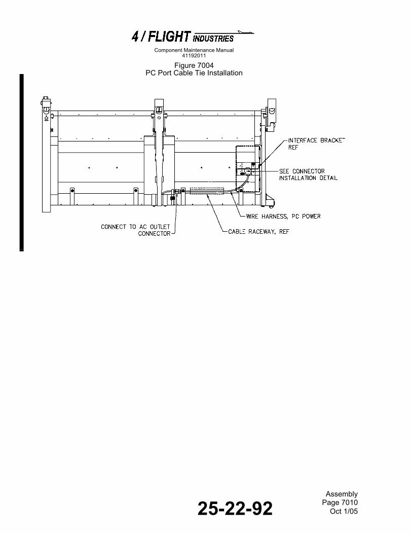
25-22-92 Page 7010Oct 1/05
Assembly
Component Maintenance Manual41192011
Figure 7004
PC Port Cable Tie Installation
Figure 7005

25-22-92 Page 7011Oct 1/05
Assembly
Component Maintenance Manual41192011
Figure 7005 (Sheet 1 of 3)
IFE Cable Routing
38978-13-s1
CABLETIE
CABLETIE
VDU TO VDUJUMPER
IFE CABLEASSEMBLY
VDU TO VDUJUMPER
IFE CABLEASSEMBLY
SERVICELOOP FORSLACKCABLE

25-22-92 Page 7012Oct 1/05
Assembly
Component Maintenance Manual41192011
Figure 7005 (Sheet 2 of 3)
IFE Cable Routing

25-22-92 Page 7013Oct 1/05
Assembly
Component Maintenance Manual41192011
Figure 7005 (Sheet 3 of 3)
IFE Cable Routing
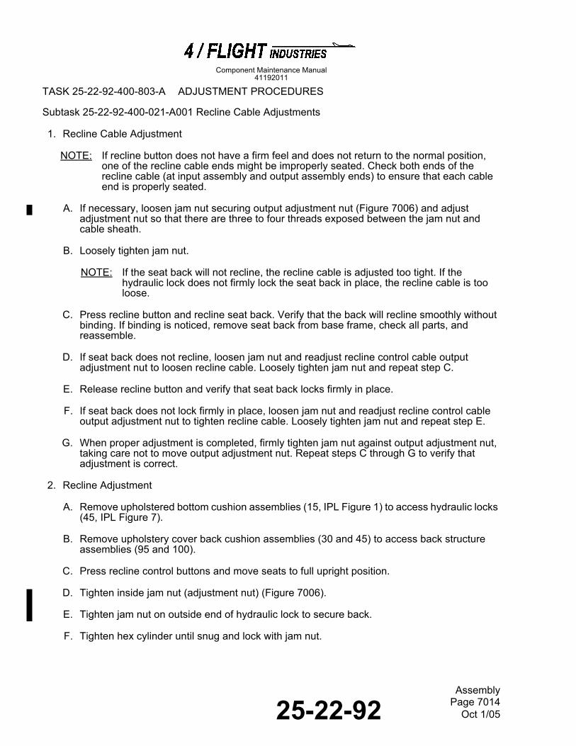
25-22-92 Page 7014Oct 1/05
Assembly
Component Maintenance Manual41192011
TASK 25-22-92-400-803-A ADJUSTMENT PROCEDURES
Subtask 25-22-92-400-021-A001 Recline Cable Adjustments 5
1. Recline Cable Adjustment
NOTE: If recline button does not have a firm feel and does not return to the normal position, one of the recline cable ends might be improperly seated. Check both ends of the recline cable (at input assembly and output assembly ends) to ensure that each cable end is properly seated.
A. If necessary, loosen jam nut securing output adjustment nut (Figure 7006) and adjust adjustment nut so that there are three to four threads exposed between the jam nut and cable sheath.
B. Loosely tighten jam nut.
NOTE: If the seat back will not recline, the recline cable is adjusted too tight. If the hydraulic lock does not firmly lock the seat back in place, the recline cable is too loose.
C. Press recline button and recline seat back. Verify that the back will recline smoothly without binding. If binding is noticed, remove seat back from base frame, check all parts, and reassemble.
D. If seat back does not recline, loosen jam nut and readjust recline control cable output adjustment nut to loosen recline cable. Loosely tighten jam nut and repeat step C.
E. Release recline button and verify that seat back locks firmly in place.
F. If seat back does not lock firmly in place, loosen jam nut and readjust recline control cable output adjustment nut to tighten recline cable. Loosely tighten jam nut and repeat step E.
G. When proper adjustment is completed, firmly tighten jam nut against output adjustment nut, taking care not to move output adjustment nut. Repeat steps C through G to verify that adjustment is correct.
2. Recline Adjustment
A. Remove upholstered bottom cushion assemblies (15, IPL Figure 1) to access hydraulic locks (45, IPL Figure 7).
B. Remove upholstery cover back cushion assemblies (30 and 45) to access back structure assemblies (95 and 100).
C. Press recline control buttons and move seats to full upright position.
D. Tighten inside jam nut (adjustment nut) (Figure 7006).
E. Tighten jam nut on outside end of hydraulic lock to secure back.
F. Tighten hex cylinder until snug and lock with jam nut.

25-22-92 Page 7015Oct 1/05
Assembly
Component Maintenance Manual41192011
Subtask 25-22-92-400-022-A001 Foodtable Adjustment 6
1. Foodtable and Arm Setscrew Adjustment
A. With foodtray assembly (145, IPL Figure 1) in the stowed position, adjust its setscrews until foodtray is parallel to foodtray arms (160, 165, 170, and 175, IPL Figure 7) (Figure 7006). This will ensure that foodtray assembly is secure and not protruding when stowed.
B. With foodtray assembly (145, IPL Figure 1) in the deployed position, adjust its setscrews until foodtray is parallel to foodtray arms (160, 165, 170, and 175, IPL Figure 7) in deployed position (Figure 7006).
2. Foodtray Stop Adjustment
A. Remove upholstered bottom cushion assemblies (15, IPL Figure 1) and back cushion assemblies (30 and 45) to access foodtray stop assemblies (255 and 260, IPL Figure 10).
B. Measure the horizontal angle of foodtray assembly (145, IPL Figure 1). Use bottom of leg (420, IPL Figure 10) to obtain a horizontal plane.
NOTE: Ensure that the foodtray arms (160, 165, 170, and 175, IPL Figure 7) are in contact with adjustment screws (Figure 7007).
C. Turn adjustment screws in foodtray stops to achieve a 2.0 degree rise from horizontal (Figure 7007).
NOTE: Both ends of the adjustment screws are slotted, so adjustment can be made from either the front or rear of the seat assembly.
Figure 7006
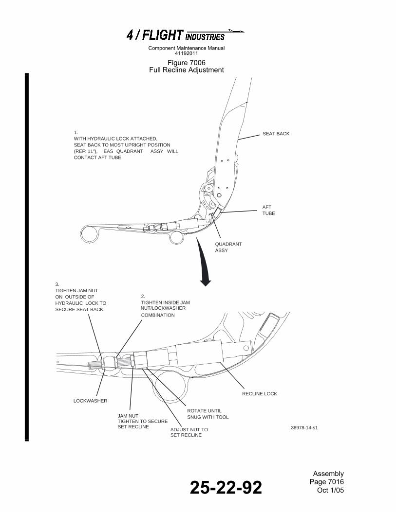
25-22-92 Page 7016Oct 1/05
Assembly
Component Maintenance Manual41192011
Figure 7006
Full Recline Adjustment
Figure 7007
38978-14-s1
1.WITH HYDRAULIC LOCK ATTACHED,SEAT BACK TO MOST UPRIGHT POSITION(REF: 11"), EAS QUADRANT ASSY WILLCONTACT AFT TUBE
2.TIGHTEN INSIDE JAMNUT/LOCKWASHER
COMBINATION
3.TIGHTEN JAM NUTON OUTSIDE OFHYDRAULIC LOCK TOSECURE SEAT BACK
LOCKWASHER
JAM NUTTIGHTEN TO SECURESET RECLINE
ROTATE UNTILSNUG WITH TOOL
RECLINE LOCK
SEAT BACK
QUADRANTASSY
AFTTUBE
ADJUST NUT TO SET RECLINE
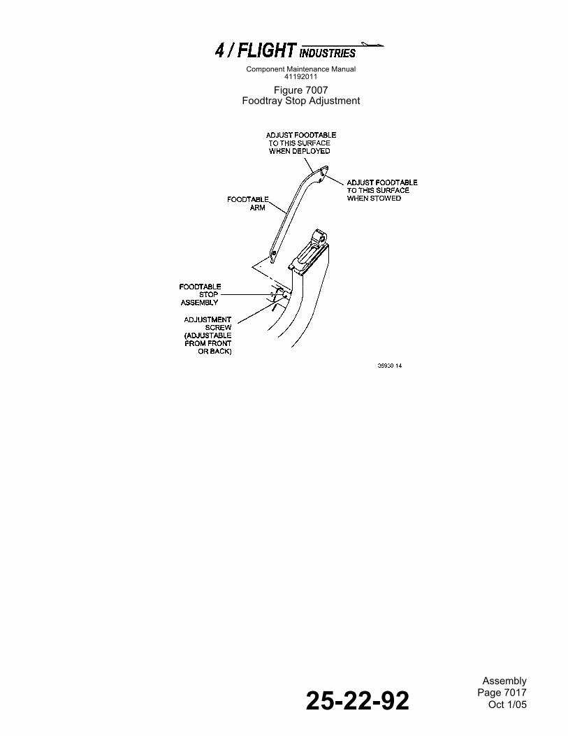
25-22-92 Page 7017Oct 1/05
Assembly
Component Maintenance Manual41192011
Figure 7007
Foodtray Stop Adjustment

25-22-92 Page 7018Oct 1/05
Assembly
Component Maintenance Manual41192011
THIS PAGE IS INTENTIONALLY LEFT BLANK

25-22-92 Page 8001Oct 1/05
Fits and Clearances
Component Maintenance Manual41192011
FITS AND CLEARANCES
80008000
TASK 25-22-92-800-801-A GENERAL INFORMATION FOR FITS AND CLEARANCES
Subtask 25-22-92-800-001-A001 General Information 1
1. This section gives dimensional information to let the technician find if the assembly is serviceable or make a decision about the level of repair that is necessary.
TASK 25-22-92-800-802-A TORQUE LIMITS
Subtask 25-22-92-800-002-A001 Assembly Torque Limits 2
1. The Assembly Torque Limits in Table 8001 give applicable torque limits for all critical fasteners. The torque values are shown in the English (inch-pounds) standard value followed by the Metric (N•m) equivalent in parentheses.
Table 8001Assembly Torque Limits
Thread Size Minimum Tension Maximum Tension Minimum Shear Maximum Shear
8-32 12 inch-pounds (1,3 N•m)
15 inch-pounds (1,7 N•m)
7 inch-pounds(0,8 N•m)
9 inch-pounds (1,0 N•m)
10-32 20 inch-pounds(2,2 N•m)
25 inch-pounds(2,8 N•m)
12 inch-pounds(1,3 N•m)
15 inch-pounds(1,7 N•m)
1/4-28 50 inch-pounds(5,6 N•m)
70 inch-pounds(7,9 N•m)
30 inch-pounds(3,4 N•m)
40 inch-pounds(4,5 N•m)
5/16-24 100 inch-pounds(11,2 N•m)
140 inch-pounds(15,7 N•m)
60 inch-pounds(6,7 N•m)
85 inch-pounds9,6 N•m)
3/8-24 160 inch-pounds(18,0 N•m)
190 inch-pounds(21,3 N•m)
95 inch-pounds(10,7 N•m)
110 inch-pounds(12,4 N•m)

25-22-92 Page 8002Oct 1/05
Fits and Clearances
Component Maintenance Manual41192011
THIS PAGE IS INTENTIONALLY LEFT BLANK

25-22-92 Page 9001Oct 1/05
Component Maintenance Manual41192011
Special Tools, Fixtures, Equipment and Consumables
SPECIAL TOOLS, FIXTURES, EQUIPMENT AND CONSUMABLES
90009000
TASK 25-22-92-940-801-A MATERIALS AND TOOLS
Subtask 25-22-92-940-001-A001 Consumable Materials 1
1. The consumable materials needed for the seat assembly are given in Table 9001.
Table 9001Consumable Materials
Material Number and Name Source Use
A-A-59282, Alcohol, Ethyl Commercially available To clean components prior to repair.
BZT-69, Thread, Nylon or
V-T-295, Type I, Class A, Size FFl
4/Flight Industries (V34696)
Commercially available
To repair upholstery seam and Velcro.
CALLA 301-A LEMON, Detergent, Aqueous Anionic
Zip-Chem Prod., Inc. (V8E913) To clean molded plastic areas, clean metal parts, and remove adhesive.
-, Cleaner, Foam Dupont E. I. De Nemours Co., Inc. (V2H935)
To clean fabric.
-, Cleaner, Glamorene Glamorene Products Corp.(V21440)
To clean fabric.
-, Cleaner, Mystic Foam Mystic Foam Corp. (S00001) To clean fabric.
-, Cleaner, Duo-Dellay Duo-Dellay Products Co. (S00002)
To clean fabric.
-, Cloths, Cotton (clean and dry)
Commercially available To clean components prior to repair.
-, Detergent, Mild Household Commercially available To clean molded plastic areas.
DP100, Adhesive 3M Co. (V6A669) To install Velcro.
-, Fluid, Carbone Cleaning Carbone Corp. (S00003) To clean fabric.
-, Gloss, Chemical Resistant Commercially available To touch up painted surfaces.
HSH IP, Primer (light gray finish)
4/Flight Industries (V34696) To touch up painted surfaces.
IP 1065, Paint, Light Gray Top Coat (Color FV3214)
4/Flight Industries (V34696) To touch up painted surfaces.

25-22-92 Page 9002Oct 1/05
Special Tools, Fixtures, Equipment and Consumables
Component Maintenance Manual41192011
IP 1065B, Paint Kit, Touch up (Color FV3214)
4/Flight Industries (V34696) To touch up painted surfaces.
IP 650ES, Clear Coat 4/Flight Industries (V34696) To touch up painted surfaces.
MIL-C-38334, Compound, Corrosion Removing
Commercially available To remove corrosion.
MIL-C-5441, Film, Chemical (color optional)
Commercially available To repair nicks or scratches.
MIL-T-44010, Thread, Kevlar (#10 30/3 Spun, Natural Color)
Commercially available To repair upholstery seam and Velcro.
P-C-451, Cloth, Abrasive (Aluminum Oxide, Medium Grit)
Commercially available To replace bonded components.
P-C-458, Cloth, Crocus Commercially available To repair nicks or scratches.
MIL-PRF-680, Type III, Solvent, Degreasing (optional)
Commercially available To clean metal parts.
PLT1.5M, PLT2SM, PLT3SM, and 41031224-1, Ties, Cable
4/Flight Industries (V34696) To secure the recline control cable.
-, Solvent, Cleaning (Aliphatic Naphtha)
Commercially available To clean metal parts.
-, Solvent, Cleaning Agent, Dupont Dry Cleaner
Dupont E. I. De Nemours Co., Inc. (V2H935)
To clean fabric.
-, Solvent, Impregnated Powder, Powder-ene
Von Schrader Co. (V23738) To clean fabric.
#0166, Lubricant, Silicone Zep Manufacturing Co.(V27674)
To clean metal parts.
815MX, Detergent, Aqueous Anionic
Brulin & Co. (V94058) To clean molded plastic areas, clean metal parts, and remove adhesive.
-, Swab, Cotton Commercially available To clean components prior to repair.
Material Number and Name Source Use

25-22-92 Page 9003Oct 1/05
Component Maintenance Manual41192011
Special Tools, Fixtures, Equipment and Consumables
Subtask 25-22-92-94B-091-A001 Special Tools and Test Equipment 2
1. The special tools and test equipment needed for the seat assembly are given in Table 9002.
NOTE: Equivalent substitutes may be used for the items listed.
Table 9002Special Tools and Test Equipment
Tool Number and Name Source Use
-, Apron Commercially available To protect the body when using solvents and detergents.
-, Bottle, Spray Commercially available To apply prepared detergent solutions.
-, Brush, Soft-Bristled Commercially available To apply prepared detergent solutions.
-, Gloves, Chemical Resistant Commercially available To protect the hands when using cleaning solvents.
-, Goggles, Eye Safety Commercially available To protect the eyes when using cleaning solvents.
-, Needle, Fisherman’s Commercially available To repair Velcro on seat covers.
-, Tool, Rivet Installation Commercially available To replace rivets.
, Vacuum Commercially available To clean fabric.
, Voltmeter, Digital Commercially available To perform IFE continuity checks.

25-22-92 Page 9004Oct 1/05
Special Tools, Fixtures, Equipment and Consumables
Component Maintenance Manual41192011
THIS PAGE IS INTENTIONALLY LEFT BLANK

25-22-92 Page 10001Oct 1/05
Illustrated Parts List
Component Maintenance Manual41192011
ILLUSTRATED PARTS LIST
TASK 25-22-92-950-801-A GENERAL
Subtask 25-22-92-99F-001-A001 General 1
1. This section lists, describes, and illustrates all component assemblies, subassemblies, and parts required for maintenance of the seat assemblies.
Subtask 25-22-92-99F-002-A001 Scope of Information 2
1. General
A. Each assembly is listed and immediately followed by a listing of its detail parts. The listing is indentured to show the relationship between each part and its next higher assembly. Item numbers in the parts list correspond to the item numbers of the accompanying illustration (figure).
2. How to Identify a Part
A. When the part number is known: Find the part number in the numerical index and note the figure and item number. Find the item number in the applicable parts list and illustration to get the necessary information.
B. When the part number is not known: Review the illustrations to identify the part by physical appearance and location. Refer to the accompanying parts list to get the part number, nomenclature, effectivity, and quantity.
C. The effectivity code shows the part usage relative to the next higher assembly. When the EFFECTIVITY CODE column is blank, the part usage applies to all next-higher-assembly versions unless otherwise specified in the NOMENCLATURE column.
Subtask 25-22-92-960-003-A001 Equipment Designator Index 3
1. The Equipment Designator Index is an aid to find the parts in the Detail Parts List by equipment designator. The equipment designator, the part number, the figure number, and the item number are given for each entry.
2. The equipment designators are sorted one character at a time, from left to right. The correct sequence is (1) dash, (2) letters A through Z, and (3) numerals 0 through 9.
Subtask 25-22-92-990-001-A001 Numerical Index 4
1. The Numerical Index is an aid to find parts in the Detail Parts List by part number. The figure number, the item number, and the total quantity required are given for each entry.
2. The part numbers are sorted one character at a time, from left to right. The correct sequence is (1) dash, (2) letters A through Z, and (3) numerals 0 through 9.

25-22-92 Page 10002Oct 1/05
Illustrated Parts List
Component Maintenance Manual41192011
Subtask 25-22-92-950-005-A001 Explanation of Detail Parts List Entries 5
1. The Detail Parts List is arranged in general sequence of disassembly. The parts are illustrated in an exploded view illustration and listed in the related parts list.
A. FIG. ITEM Column
(1) The first number at the top of each FIG. ITEM column is the figure number of the exploded-view illustration. The number given opposite each part number is the item number assigned to the part in the illustration.
(2) A dash (-) in front of an item number means the part is not illustrated.
(3) Alpha-variants A through Z (except I and O) are assigned to item numbers when necessary to identify added parts, alternate parts, and parts modified by service bulletins.
B. PART NUMBER Column
(1) This column gives the part number of the manufacturer for each part, as modified to meet the requirements of ATA 200/2000. The modifications can include:
(a) Removal of blank spaces and special characters, with the possible exception of dashes. Dashes are permitted only between numeric characters.
(b) Insertion of a reference part number compatible with ATA 200/2000 if the part number is longer than 15 characters. In these cases, the full part number is given in the NOMENCLATURE column.
C. INDENTure Column
(1) The indenture column is used to show the relationship of one part to another as found on the original engineering drawings. A typical indenture relationship is shown in Table 10001.
Table 10001Parts Indentation Level
End Item or Major Assembly
. Detail Parts for End Item or Major Assembly
. . Subassemblies
ATTACHING PARTS
. . Attaching Parts for Subassemblies
---*---
. . . Detail Parts for Subassemblies

25-22-92 Page 10003Oct 1/05
Illustrated Parts List
Component Maintenance Manual41192011
D. NOMENCLATURE Column
(1) This column contains descriptive nomenclature for each part, and can also give the CAGE code of the manufacturer (if the part is not made by 4/Flight Industries), the part number (if it is longer than 15 digits or modified to ATA 200/2000), any service bulletin that affects the part, and any obsolete part numbers. The column also provides figure references for NHA and details, and additional descriptive information as required.
(2) Assemblies, subassemblies, and detail parts subjected to modification, deletion, addition, or replacement by an issued service bulletin are annotated to indicate both the pre- and post-service bulletin configurations. The term (PRE SB XXXX) in the NOMENCLATURE column identifies the original configuration, and the term (POST SB XXXX) identifies assemblies and parts after the modification has been completed.
(3) The terms defined in Table 10002 are used when applicable to indicate the interchangeability of parts.
Table 10002Definitions for the Illustrated Parts List
E. EFF CODE Column
(1) This column contains effectivity codes (A, B, etc.) to indicate the alternate models or configurations of the end items to which the parts apply. This column is left blank when the parts apply to all models or configurations in the parts list. When an asterisk (*) is used, the part is contained in a kit which is listed at the end of the detail parts lists.
ATTACHING PARTS
. . Attaching Parts for Detail Parts
---*---
Term Abbreviation Definition
Alternate ALT The listed part is alternate to, and interchangeable with, other parts within the same item number variant group or other item numbers if designated.
Superseded By SUPSD BY The part is replaced by and is not interchangeable with the item number designated in the notation.
Supersedes SUPSDS The part replaces and is not interchangeable with the item number designated in the notation.
Replaced By REPLD BY The part is replaced by and is interchangeable with the item number designated in the notation.
Replaces REPLS The part replaces and is interchangeable with the item number designated in the notation.
Non Procurable NP The part is not available separately; the next higher assembly must be ordered.

25-22-92 Page 10004Oct 1/05
Illustrated Parts List
Component Maintenance Manual41192011
F. UNITS PER ASSY Column
(1) The quantity shown in this column is the units required for one next higher assembly (NHA). The abbreviation RF (reference) means the end item or assembly is shown completely assembled in the figure referenced in the NOMENCLATURE column.
Subtask 25-22-92-980-001-A001 Manufacturer Names and Addresses 6
1. The CAGE codes for the manufacturers of the parts, special tools, test equipment, and materials referenced in the manual are given below. The five digit code is preceded by the letter V. The codes are taken from Cataloging Handbook H4/H8. No code in the NOMENCLATURE column means the part is made by 4/Flight Industries.
VENDOR LIST
Code Name and Address
V00001 Mesag-System ag DivisionAircraft PartsRheinstrasse 36dCH-9444 Diepoldsau/Switzerland
V0EV66 Girard Fasteners and Supply Co.631 S. Palm St.La Habra, CA 90631
V01556 Emhart Fastening Systems GroupHeli-Coil Div.510 River Rd.Shelton, CT 06484
V02953 P.L. Porter Co.6355 De Soto Ave.Woodland Hills, CA 91367-2687
V06383 Panduit Corp.17301 Ridgeland Ave.Tinley Park, IL 60477-0981
V3A054 McMaster-Carr Supply Co.9630 Norwalk Blvd.Santa Fe Springs, CA 90670-2932
V3DCM5 Index Fasteners, Inc.945 E. Grevillea Ct.Ontario, CA 91761
V31272 Ancra International. Corp.4880 W. Rosecrans Ave.Hawthorne, CA 90250
V34696 4/Flight Industries1945 S. Grove Ave.Ontario, CA 91761

25-22-92 Page 10005Oct 1/05
Illustrated Parts List
Component Maintenance Manual41192011
V45722 USM Corp.
Sub. of Emhart Industries Inc.Parker-Kalon Fastener Div.Campbellsville, KY 42718
V56135 C and D Aerospace14 Center PointeLa Palma, CA 90623
V56958 The Young Engineers, Inc.25841 Commerce Centre Dr.Lake Forest, CA 92630
V56988 Century Springs Corp.222 E. 16th St.Los Angeles, CA 90015-3636
V6A669 Minnesota Mining & Mfg. Co. (3M Co.)10260 Alliance Rd.Cincinnati, OH 45250
V79136 Seeger, Inc.Waldes Truarc Div.70 E. Willow St.Millburn, NJ 07041
V8E913 Zip-Chem Prod., Inc.400 Jarvis Dr.Morgan Hill, CA 95037
V84830 Lee Spring Co., Inc.1462 62nd St.Brooklyn, NY 11219
V86298 Crepe Kraft Co.Camden, NJ 08100
V86928 Seastrom Mfg. Co., Inc.456 Seastrom St.Twin Falls, ID 83301-8526
V94058 Brulin and Co., Inc.DBA Brulin Corp.2920 Dr. Andrew J. Brown Ave.P.O. Box 270Indianapolis, IN 46206-0270
V98474 Compar Corp.Burlingame, CA 94010
Code Name and Address

25-22-92 Page 10006Oct 1/05
Illustrated Parts List
Component Maintenance Manual41192011
THIS PAGE IS INTENTIONALLY LEFT BLANK

25-22-92 Page 10007Oct 1/05
Illustrated Parts List
Airline Total Airline TotalPart Number Part Number Fig - Item Req. Part Number Part Number Fig - Item Req.
Component Maintenance Manual41192011
NUMERICAL INDEX
A127011-501 4 - 40 1A127012-501 4 - 55 1A127013-501 4 - 60 1A127015-501 4 - 45A127015-505 5A - 80 2AN316-3R 7 - 75 4AN960-10L 1 - 75 4AN960-10L 1 - 90 8AN960-10L 2 - 45A 1AN960-10L 3 - 65 2 AN960-10L 10 - 20 3AN960-10L 10 - 165 2AN960-10L 10 - 245 4AN960-10L 10 - 380 2AN960-416 7 - 55 4AN960-416 10 - 332A 2AN960-416 10 - 355G 2AN960-416L 1 - 95 4AN960-416L 7 - 310B 2AN960-416L 10 - 90 4AN960-416L 10 - 330 4AN960-416L 10 - 355 6AN960-416L 10 - 355B 8AN960-416L 10 - 355D 4AN960-416L 10 - 355H 2 AN960-516 10 - 185 1AN960-516L 10 - 195 2AN960-616 7 - 120 2AN960-6L 3 - 90B 13AN960-6L 3 - 90C 7AN960-8 7 - 15A 3AN960-8 7 - 35 5AN960-8 7 - 190 12AN960-8 7 - 190C 12AN960-8 7 - 205 4AN960-8 7 - 220 4AN960-8 10 - 140 4AN960-818 7 - 140 6AN960-8L 7 - 15C 3AN960-8L 7 - 35C 5AN960-8L 7 - 205C 4AN960-8L 7 - 220C 4AN960-8L 8A - 25A 2AN960-8L 9 - 25 2AN960C416 2 - 15 2
AN960C416 2 - 15A 1B56 5 - 30BS18303-3A 8 - 75 2BS18303-3A 10 - 270 4CA01031-00 9 - 55 1CDSP5801-3AL 8 - 40 4CDSP5801-3AL 10 - 385 2F52NKTE054 10 - 180 1K27 10 - 120 1LC026C1 7 - 275 1LC032E1 2 - 20 1MC03866-00 9 - 50 1MC04685-70 9 - 60 1MC06685-00 9 - 45 1MC71-32 9 - 40A 1MC90251-00 9 - 70 1MS16555-331 10 - 405 1MS16555-332 10 - 405A 1MS16632-2025 9 - 65 1MS171498 2 - 10A 1MS171587 10 - 25 2MS171587 10 - 65 2MS171587 10 - 97 2MS21042-08 10 - 135 2MS21042L3 1 - 85 4MS21042L3 8 - 30 2MS21042L4 7 - 50 2MS21042L4 10 - 80 2MS21042L4 10 - 325 3MS21042L4 10 - 325A 2MS21042L4 10 - 350 3MS21245L8 7 - 135 2MS21266-1N 3 - 66 ARMS21266-2N 3 - 51 ARMS24665-151 2 - 10 1MS24694C51 8 - 45 2MS25281F4 7 - 225 2MS25281F4 7 - 225A 1MS25281F6 4 - 20 1MS35333-42 7 - 80 4NAS1081-04A4P 7 - 270 1NAS1096-3-6 3 - 60 2NAS1149C0463R 2 - 15B 2NAS1149C0463R 2 - 15C 1NAS1149F0332P 1 - 75A 4

25-22-92 Page 10008Oct 1/05
Illustrated Parts List
Airline Total Airline TotalPart Number Part Number Fig - Item Req. Part Number Part Number Fig - Item Req.
Component Maintenance Manual41192011
NAS1149F0332P 1 - 90A 8NAS1149F0332P 2 - 45 1NAS1149F0332P 3 - 65A 2NAS1149F0332P 5A - 45 2NAS1149F0332P 5A - 75 1NAS1149F0332P 8 - 35 2NAS1149F0332P 10 - 20A 3NAS1149F0332P 10 - 165A 2NAS1149F0332P 10 - 245A 4NAS1149F0332P 10 - 380A 2NAS1149F0432P 1 - 95A 4NAS1149F0432P 7 - 310A 2NAS1149F0432P 10 - 90A 4NAS1149F0432P 10 - 330A 4NAS1149F0432P 10 - 355A 6NAS1149F0432P 10 - 355C 8NAS1149F0432P 10 - 355E 4NAS1149F0432P 10 - 355J 2NAS1149F0463P 7 - 55A 4NAS1149F0463P 10 - 332 2NAS1149F0463P 10 - 355F 2NAS1149F0532P 10 - 195A 2NAS1149F0563P 10 - 185A 1NAS1149F0663P 7 - 120A 2NAS1149F0863P 7 - 140A 6NAS1149FN616P 3 - 90 13NAS1149FN616P 3 - 90A 7NAS1149FN816P 5A - 30 4NAS1149FN816P 5A - 65 1NAS1149FN816P 7 - 15B 3NAS1149FN816P 7 - 35B 5NAS1149FN816P 7 - 190B 12NAS1149FN816P 7 - 205B 4NAS1149FN816P 7 - 220B 4NAS1149FN816P 9 - 25A 2NAS1149FN832P 7 - 15 3NAS1149FN832P 7 - 35A 5NAS1149FN832P 7 - 190A 12NAS1149FN832P 7 - 205A 4NAS1149FN832P 7 - 220A 4NAS1149FN832P 8A - 25 2NAS1304-11 7 - 60A 2NAS1304-12 7 - 60 4NAS1306-25 7 - 105 1NAS1306-30 7 - 110 1NAS1351-6-8 8A - 36 1NAS1352-08-8 7 - 25 1
NAS43DD6-16N 7 - 145A 2NAS43DD6-20N 7 - 125 2NAS43DD8-16N 7 - 125A 2NAS43DD8-20N 7 - 145 2NAS514P1032-12 10 - 55 1NAS514P1032-5 7 - 260 1NAS514P1032-7 8 - 50 2NAS514P1032-8 6 - 10 2NAS514P632-3 5 - 15NAS514P832-6 10 - 115 1NAS514P832-7 1 - 130 8NAS514P832-7 2 - 55 2NAS514P832-7 10 - 115A 1NAS517-2-6 5A - 10 1NAS517-3-3 10 - 400 2NAS517-3-7 10 - 390 2NAS600-4 1A - 20 4NAS600-4 2 - 65 1NAS601-4 9 - 35NAS601-5 1A - 35 12NAS601-5 3 - 6 4NAS601-5 3 - 40 8NAS601-6 3 - 20 4NAS601-6 3 - 45NAS602-10 10 - 145A 2NAS602-5 7 - 185A 12NAS602-5 7 - 215A 4NAS602-6 5A - 25 4NAS602-6 5A - 60 1NAS602-6 7 - 185 12NAS602-6 7 - 215 4NAS602-7 7 - 10 3NAS602-7 7 - 30 5NAS602-8 7 - 200 4NAS602-8 10 - 145 2NAS603-10 10 - 160 2NAS603-12 10 - 15 1NAS603-21 4 - 25 1NAS603-4 2 - 40 1NAS603-6 7 - 230 2NAS603-6 7 - 230A 1NAS603-6 10 - 10 2NAS603-7 1 - 70 4NAS603-7 1 - 100 4NAS603-7 5A - 40 2NAS603-7 5A - 70 1NAS603-7 10 - 240 4

25-22-92 Page 10009Oct 1/05
Illustrated Parts List
Airline Total Airline TotalPart Number Part Number Fig - Item Req. Part Number Part Number Fig - Item Req.
Component Maintenance Manual41192011
NAS6204-21 10 - 95 1NAS6204-22 10 - 95A 2NAS6204-28 10 - 365 2NAS6204-28 10 - 365B 1NAS6204-31 10 - 365A 1NAS6204-36 10 - 340 2NAS6204-36 10 - 340A 1NAS6204-36 10 - 360 1NAS6204-42 10 - 335 1NAS6205-25 10 - 205 1NAS620-5L 8 - 85 2NAS620-5L 10 - 280 4NAS623-5-20 10 - 200 1NAS6604-1 8 - 10 1NAS6604L1 8 - 10A 1NAS75-8-013 8 - 55 1NAS76A6-006 8 - 60 1PFSC35-38A 5 - 45PLT1.5M 4 - 15 2PLT1.5M 7 - 85 2PLT1.5M 7 - 85A 1PLT2SM 7 - 40 2PLT3SM 4 - 10 4PLT3SM 4 - 10A 1SD42BS 3 - 68 4SD43BS 3 - 85 13SD43BS 3 - 85A 7SD52BS 10 - 315 19SD53BS 10 - 305 13SD54BS 10 - 170 2SD54BS 10 - 310 2TYE2161-08-100 8 - 70 8TYE2161-3-7 8 - 65 2TYE2168-08-1000 8 - 70A 61693-0414 8 - 80 21693-0414 10 - 275 42010-1-59M2256 1 - 115A 22077-1-011-3577 1 - 115 12077-1-011-8003 1 - 115B 12077-1-021-3577 1 - 1202077-1-021-8003 1 - 115C 122NKTM02 10 - 375 2358506CNY207 5 - 3541031025-501 10 - 150 141031026-1 10 - 265 441031033-1 10 - 155 141031037-5 1 - 160
41031037-5 6 - 25 241031038-501 10 - 215 241031056-501 7 - 45 241031056-501M 7 - 45A 241031071-1 10 - 99 141031072-1 10 - 35 141031081-1 6 - 20 241031097-501 10 - 410 141031098-501 10 - 415 141031098-7 10 - 415A 141031104-501 10 - 220 141031105-1 10 - 250 441031110-501 7 - 150 241031133-501 10 - 235 441031135-1 10 - 210 441031224-1 7 - 90 241031224-1 7 - 90A 141031358-1 7 - 115 241031456-101 1A - 5F 141031456-103 1A - 5G 141031456-109 1A - 5H 141031456-111 1A - 5J 141031456-113 1A - 5K 141031456-115 1A - 5L 141031456-117 1A - 5M 141031456-119 1A - 5N 141031456-121 1A - 5P 141031456-123 1A - 5Q 141031456-89 1A - 5 141031456-91 1A - 5A 141031456-93 1A - 5B 141031456-95 1A - 5C 141031456-97 1A - 5D 141031456-99 1A - 5E 141041031-501 10 - 225 141071030-543 1 - 110 44119030-19 10 - 395 141191006-1 10 - 420 141191006-2 10 - 420A 141191006-3 10 - 420B 141191006-4 10 - 420C 141191007-503 10 - 430 141191007-504 10 - 430A 141191007-505 10 - 430B 141191007-506 10 - 430C 141191018-1 10 - 30 141191018-2 10 - 30A 1

25-22-92 Page 10010Oct 1/05
Illustrated Parts List
Airline Total Airline TotalPart Number Part Number Fig - Item Req. Part Number Part Number Fig - Item Req.
Component Maintenance Manual41192011
41191018-3 10 - 45 141191018-501 10 - 5A 141191018-501 10 - 5G 141191018-502 10 - 5 141191018-502 10 - 5F 141191021-505 7 - 20 141191021-506 7 - 20A 141191022-505 7 - 5 141191022-506 7 - 5A 141191023-503 10 - 425 141191023-504 10 - 425A 141191024-505 10 - 435 141191024-506 10 - 435A 141191028-1 10 230 141191028-2 10 - 230A 141191030-503 10 - 345 141191030-503 10 - 345H 141191030-504 10 - 345A 141191030-504 10 - 345J 141191030-507 9 - 80 141191030-508 9 - 80A 141191030-509 10 - 345D 141191030-509 10 - 345K 141191030-510 10 - 345E 141191030-510 10 - 345L 141191030-515 10 - 320B 141191030-516 10 - 320C 141191030-517 10 - 345B 141191030-518 10 - 345C 141191030-519 10 - 320 141191030-519 10 - 320F 141191030-520 10 - 320A 141191030-520 10 - 320G 141191030-523 10 - 320D 141191030-524 10 - 320E 141191030-525 10 - 345F 141191030-526 10 - 345G 141191031-501 10 - 255 341191031-505 10 - 260 141191032-5 10 - 295 1 41191032-6 10 - 295A 141191032-7 10 - 300 1 41191032-8 10 - 300A 141191033-1 7 - 250 141191033-1 7 - 295 141191033-1 7 - 315 141191034-1 7 - 265 1
41191034-3 8A - 35 141191034-3 9 - 7541191035-3 8A - 15 141191035-3 9 - 15 141191045-527 8A - 40 141191045-528 8A - 40A 141191045-529 8A - 40B 141191057-501 1 - 165 241191060-505 2 - 5 141191069-1 7 - 155 141191070-1 7 - 70 141191070-501 7 - 65 141191071-501 10 - 370 241191073-509 8A - 5 141191073-509 9 - 5 141191074-521 1 - 145 241191075-501 7 - 160 141191075-502 7 - 165 141191075-503 7 - 170 141191075-504 7 - 175 141191080-541 7 - 235 141191080-541 8A - 1 RF41191080-542 7 - 235A 141191080-542 8A - 1A RF41191080-545 7 - 280A 141191080-545 8A - 1B RF41191080-546 7 - 280 141191080-546 8A - 1C RF41191080-557 7 - 235B 141191080-557 8A - 1D RF41191080-559 7 - 280B 141191080-559 8A - 1E RF41191090-1 7 - 255 141191091-501 8A - 30 141191091-501 9 - 4041191121-523 1 - 20 141191127-3 10 - 70 241191127-501 10 - 40 141191142-519 1 - 15 241191143-505 1 - 25 141191151-1 2 - 25 141191161-503 2 - 5A 141191169-1 2 - 25A 141191169-3 2 - 26 141191174-505 1 - 65 241191175-513 1 - 60 241191187-501 1 - 40A 1

25-22-92 Page 10011Oct 1/05
Illustrated Parts List
Airline Total Airline TotalPart Number Part Number Fig - Item Req. Part Number Part Number Fig - Item Req.
Component Maintenance Manual41192011
41191189-1 1 - 150 441191202-1 5 - 5041191202-501 3 - 3041191202-501 5 - 141191203-1 3 - 1541191205-501 7 - 320 141191205-501 10 - 1 RF41191205-502 7 - 320A 141191205-502 10 - 1A RF41191205-503 7 - 320D 141191205-503 10 - 1B RF41191205-504 7 - 320E 141191205-504 10 - 1C RF41191205-505 7 - 320B 141191205-505 10 - 1D RF41191205-506 7 - 320C 141191205-506 10 - 1E RF41191205-507 7 - 320K 141191205-507 10 - 1F RF41191205-508 7 - 320L 141191205-508 10 - 1G RF41191205-513 7 - 320F 141191205-513 10 - 1H RF41191205-514 7 - 320G 141191205-514 10 - 1J RF41191205-515 7 - 320H 141191205-515 10 - 1K RF41191205-516 7 - 320J 141191205-516 10 - 1L RF41191209-501 8 - 120 1 41191209-502 8 - 120A 141191210-517 7 - 235C41191210-517 9 - 141191210-518 7 - 235D41191210-518 9 - 1A41191210-519 7 - 300A 141191210-519 9 - 1B RF41191210-520 7 - 300B 141191210-520 9 - 1C RF41191210-521 7 - 300 141191210-521 9 - 1D RF41191212-1 2 - 35 141191216-505 5A - 35 241191217-7 9 - 3041191222-501-17 3 - 100 241191222-501-8 3 - 9541191223-501 4 - 5
41191225-501 1 - 80 241191227-503 1 - 145A 241191227-503 6 - 1 RF41191227-601 6 - 30 141191227-603 6 - 30A 141191230-505 9 - 80D 141191230-507 9 - 80B 141191230-508 9 - 80C 141191237-501 1 - 40 141191240-501 7 - 280C 141191242-501 10 - 75 141191242-502 10 - 75A 141191242-503 10 - 75B 141191242-504 10 - 75A 141191243-501 10 - 98 141191243-501 10 - 10041191244-3 10 - 50 141191244-5 10 - 130 141191244-501 10 - 60 141191244-6 10 - 130A 141191244-7 10 - 96 141191245-3 10 - 110 141191245-501 10 - 105 141191245-502 10 - 105A 141191245-503 10 - 125 141191246-501 10 - 5B 141191246-502 10 - 5C 141191246-503 10 - 5D 141191246-504 10 - 5E 141191251-501 1 - 105 241191251-503 1 - 105A 241191255-1 5 - 4041191255-2 5 - 40A41191255-3 5 - 2541191255-501 5 - 541191255-502 5 - 1041191258-501 8 - 5 141191259-501 8 - 25 141191259-502 8 - 25A 141191260-1 8 - 15 141191261-1 8 - 20 141191263-1 3 - 75 141191263-3 3 - 80 241191263-3 3 - 80A 541191263-3 3 - 80B 241191263-5 3 - 75A 141191268-1 10 - 417 1

25-22-92 Page 10012Oct 1/05
Illustrated Parts List
Airline Total Airline TotalPart Number Part Number Fig - Item Req. Part Number Part Number Fig - Item Req.
Component Maintenance Manual41192011
41191270-501 1 - 170 141191270-501 7 - 1 RF41191270-502 1 - 170A 141191270-502 7 - 1A RF41191270-503 1 - 170B 141191270-503 7 - 1B RF41191270-504 1 - 170C 141191270-504 7 - 1C RF41191270-505 1 - 170D 141191270-505 7 - 1D RF41191270-506 1 - 170E 141191270-506 7 - 1E RF41191270-507 1 - 170F 141191270-507 7 - 1F RF41191270-508 1 - 170G 141191270-508 7 - 1G RF41191272-501 7 - 210 241191272-503 7 - 180 241191273-501 2 - 70 141191273-503 2 - 70A 141191273-504 2 - 70B 141191274-501 1 - 125 241191274-501 2 - 1 RF41191274-503 1 - 125A 241191274-503 2 - 1A RF41191274-504 1 - 125B 241191274-504 2 - 1B RF41191276-503 1 - 55 141191277-501 1 - 35 141191277-503 1 - 50 141191278-1 8 - 116 AR41191278-3 8 - 110 141191278-5 8 - 115 141191278-501 7 - 95 141191278-501 8 - 1 RF41191278-502 7 - 100 141191278-502 8 - 1A RF41191279-501 8 - 120B 1 41191279-502 8 - 120C 141191280-1 3 - 5 241191281-501 1 - 30 241191281-503 1 - 45 241191282-501 3 - 10 241191285-501 1 - 140 141191285-501 4 - 1 RF41191285-502 1 - 140A 141191285-502 4 - 1A RF
41191285-503 1 - 140B 141191285-503 4 - 1D RF41191285-504 1 - 140C 141191285-504 4 - 1E RF41191285-505 4 - 1B RF41191285-506 4 - 1C RF41191286-501 5A - 1 RF41191287-3 7 - 195 441191287-501 2 - 50 241191288-1 3 - 55 141191289-501 3 - 67 141191290-501 1 - 135 141191290-501 3 - 1 RF41191290-502 1 - 135A 141191290-502 3 - 1A RF41191290-503 1 - 135B 141191290-503 3 - 1B RF41191290-504 1 - 135C 141191290-504 3 - 1C RF41191291-1 4 - 30 141191292-3 5A - 15 141191292-501 5A - 5 141191293-3 5A - 55 141191293-501 5A - 20 141191294-501 5A - 50 141191295-501 1A - 10 141191296-501 3 - 35 241191298-501 4 - 6 141191298-502 4 - 7 141191299-501 1A - 15 241191299-501 2 - 60 141191300-501 1A - 30 241191301-501 1A - 25 241191301-501 4 - 5041192011-101 1 - 1 RF41192011-102 1 - 1A RF41192011-103 1 - 1B RF41192011-104 1 - 1C RF41192011-105 1 - 1D RF41192011-106 1 - 1E RF41192011-107 1 - 1F RF41192011-108 1 - 1G RF41194011-101 1A - 1 RF41194011-102 1A - 1A RF41194011-103 1A - 1B RF41194011-104 1A - 1C RF41194011-105 1A - 1D RF
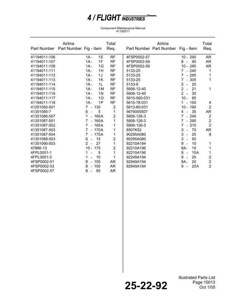
25-22-92 Page 10013Oct 1/05
Illustrated Parts List
Airline Total Airline TotalPart Number Part Number Fig - Item Req. Part Number Part Number Fig - Item Req.
Component Maintenance Manual41192011
41194011-106 1A - 1E RF41194011-107 1A - 1F RF41194011-108 1A - 1G RF41194011-111 1A - 1H RF41194011-112 1A - 1J RF41194011-113 1A - 1K RF41194011-114 1A - 1L RF41194011-115 1A - 1M RF41194011-116 1A - 1N RF41194011-117 1A - 1O RF41194011-118 1A - 1P RF41201050-501 7 - 130 241351085-7 6 - 5 141351086-507 1 - 165A 241351087-501 7 - 160A 141351087-502 7 - 165A 141351087-503 7 - 170A 141351087-504 7 - 175A 141351088-503 6 - 15 241351090-503 2 - 27 147886-13 10 - 175 24FPL0001-1 1 - 5 14FPL0001-3 1 - 10 14FSP0002-51 8 - 105 AR4FSP0002-53 8 - 100 AR4FSP0002-57 8 - 95 AR
4FSP0002-57 10 - 290 AR4FSP0002-59 8 - 90 AR4FSP0002-59 10 - 285 AR5133-25 7 - 240 15133-25 7 - 285 15133-25 7 - 305 15133-9 5 - 205606-12-40 2 - 21 15606-12-40 2 - 305610-560-031 10 - 855610-78-031 1 - 155 45613-80-031 10 - 190 25676000507 4 - 35 AR5806-126-3 7 - 245 25806-126-3 7 - 290 25806-126-3 7 - 310 28507K52 3 - 70 AR90295A080 3 - 25 890295A080 3 - 5092210A194 9 - 10 192210A196 8A - 10 192210A196 9 - 10A 192249A194 9 - 20 292949A194 8A - 20 292949A194 9 - 20A 2

25-22-92 Page 10014Oct 1/05
Illustrated Parts List
Component Maintenance Manual41192011
THIS PAGE IS INTENTIONALLY LEFT BLANK
25-22-92Illustrated Parts List
Page 10015Oct 1/05
Component Maintenance Manual41192011
DETAILED PARTS LISTIPL Figure 1, Double Seat Assembly

25-22-92Illustrated Parts List
Page 10016Oct 1/05
Component Maintenance Manual41192011
IPL Figure 1, Double Seat Assembly
38978-1
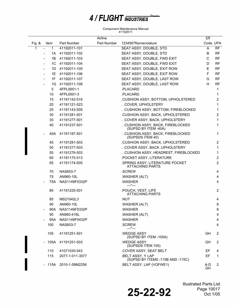
25-22-92Illustrated Parts List
Page 10017Oct 1/05
Component Maintenance Manual41192011
Airline Eff
Fig & Item Part Number Part Number 1234567Nomenclature Code UPA1 - 1 41192011-101 SEAT ASSY, DOUBLE, STD A RF
- 1A 41192011-102 SEAT ASSY, DOUBLE, STD B RF- 1B 41192011-103 SEAT ASSY, DOUBLE, FWD EXIT C RF- 1C 41192011-104 SEAT ASSY, DOUBLE, FWD EXIT D RF- 1D 41192011-105 SEAT ASSY, DOUBLE, EXIT ROW E RF- 1E 41192011-106 SEAT ASSY, DOUBLE, EXIT ROW F RF- 1F 41192011-107 SEAT ASSY, DOUBLE, LAST ROW G RF- 1G 41192011-108 SEAT ASSY, DOUBLE, LAST ROW H RF
5 4FPL0001-1 .PLACARD 110 4FPL0001-3 .PLACARD 115 41191142-519 .CUSHION ASSY, BOTTOM, UPHOLSTERED 220 41191121-523 . .COVER, UPHOLSTERY 125 41191143-505 . .CUSHION ASSY, BOTTOM, FIREBLOCKED 130 41191281-501 .CUSHION ASSY, BACK, UPHOLSTERED 235 41191277-501 . .COVER ASSY, BACK, UPHOLSTERY 140 41191237-501 . .CUSHION ASSY, BACK, FIREBLOCKED
(SUPSD BY ITEM -40A)1
- 40A 41191187-501 . .CUSHION ASSY, BACK, FIREBLOCKED(SUPSDS ITEM 40)
1
45 41191281-503 .CUSHION ASSY, BACK, UPHOLSTERED 250 41191277-503 . .COVER ASSY, BACK ,UPHOLSTERY 155 41191276-503 . .CUSHION ASSY, HEADREST, FIREBLOCKED 160 41191175-513 .POCKET ASSY, LITERATURE 265 41191174-505 .SPRING ASSY, LITERATURE POCKET
ATTACHING PARTS2
70 NAS603-7 .SCREW 475 AN960-10L .WASHER (ALT) 4
- 75A NAS1149F0332P .WASHER---*---
4
80 41191225-501 .POUCH, VEST, LIFEATTACHING PARTS
2
85 MS21042L3 .NUT 490 AN960-10L .WASHER (ALT) 8
- 90A NAS1149F0332P .WASHER 895 AN960-416L .WASHER (ALT) 4
- 95A NAS1149F0432P .WASHER 4100 NAS603-7 .SCREW
---*---4
105 41191251-501 .WEDGE ASSY(SUPSD BY ITEM -105A)
GH 2
- 105A 41191251-503 .WEDGE ASSY(SUPSDS ITEM 105)
GH 2
110 41071030-543 .COVER ASSY, SEAT BELT EF 4115 2077-1-011-3577 .BELT ASSY, Y LAP
(SUPSD BY ITEMS -115B AND -115C)EF 1
- 115A 2010-1-59M2256 .BELT ASSY, LAP (VOFWE1) A-D GH
2

25-22-92Illustrated Parts List
Page 10018Oct 1/05
Component Maintenance Manual41192011
1 - 115B 2077-1-011-8003 .BELT ASSY, Y LAP (VOFWE1)
(SUPSDS ITEM 115)EF 1
- 115C 2077-1-021-8003 .BELT ASSY, Y LAP (VOFWE1)(SUPSDS ITEM 115)
EF 1
120 2077-1-021-3577 DELETED125 41191274-501 .SHROUD ASSY, MONITOR
(RF IPL FIG. 2 FOR DETAILS)ABE-H
2
- 125A 41191274-503 .SHROUD ASSY, MONITOR, EXIT ROW(RF IPL FIG. 2 FOR DETAILS)
C 2
- 125B 41191274-504 .SHROUD ASSY, MONITOR, EXIT ROW(RF IPL FIG. 2 FOR DETAILS)ATTACHING PARTS
D 2
130 NAS514P832-7 .SCREW---*---
8
- 135 41191290-501 .INSTALLATION, IFE PROVISIONS, STD(RF IPL FIG. 3 FOR DETAILS)
ACE 1
- 135A 41191290-502 .INSTALLATION, IFE PROVISIONS, STD(RF IPL FIG. 3 FOR DETAILS)
BDF 1
- 135B 41191290-503 .INSTALLATION, IFE PROVISIONS, LAST ROW(RF IPL FIG. 3 FOR DETAILS)
G 1
- 135C 41191290-504 .INSTALLATION, IFE PROVISIONS, LAST ROW(RF IPL FIG. 3 FOR DETAILS)
H 1
- 140 41191285-501 .INSTALLATION, WIRING HARNESS, STD(RF IPL FIG. 4 FOR DETAILS)
ACE 1
- 140A 41191285-502 .INSTALLATION, WIRING HARNESS, STD(RF IPL FIG. 4 FOR DETAILS)
BDF 1
- 140B 41191285-503 .INSTALLATION, WIRING HARNESS, EXIT(RF IPL FIG. 4 FOR DETAILS)
G 1
- 140C 41191285-504 .INSTALLATION, WIRING HARNESS, EXIT(RF IPL FIG. 4 FOR DETAILS)
H 1
145 41191074-521 .FOODTRAY, ASSY ABE-H
2
- 145A 41191227-503 .FOODTRAY ASSY, SLIDING (RF IPL FIG. 6 FOR DETAILS)ATTACHING PARTS
CD 2
150 41191189-1 .SCREW 4155 5610-78-031 .WASHER, NYLON (V86928)
---*---4
160 41031037-5 DELETED165 41191057-501 .TUBE ASSY, TORSION AB
E-H2
- 165A 41351086-507 .TUBE ASSY, TORSION CD 2170 41191270-501 .STRUCTURE ASSY, DOUBLE SEAT
(RF IPL FIG. 7 FOR DETAILS)A 1
- 170A 41191270-502 .STRUCTURE ASSY, DOUBLE SEAT(RF IPL FIG. 7 FOR DETAILS)
B 1
- 170B 41191270-503 .STRUCTURE ASSY, DOUBLE SEAT (RF IPL FIG. 7 FOR DETAILS)
C 1
- 170C 41191270-504 .STRUCTURE ASSY, DOUBLE SEAT(RF IPL FIG. 7 FOR DETAILS)
D 1
- 170D 41191270-505 .STRUCTURE ASSY, DOUBLE SEAT (RF IPL FIG. 7 FOR DETAILS)
E 1
Airline EffFig & Item Part Number Part Number 1234567Nomenclature Code UPA

25-22-92Illustrated Parts List
Page 10019Oct 1/05
Component Maintenance Manual41192011
IPL Figure 1A, Double Seat Assembly
1 - 170E 41191270-506 .STRUCTURE ASSY, DOUBLE SEAT(RF IPL FIG. 7 FOR DETAILS)
F 1
- 170F 41191270-507 .STRUCTURE ASSY, DOUBLE SEAT (RF IPL FIG. 7 FOR DETAILS)
G 1
- 170G 41191270-508 .STRUCTURE ASSY, DOUBLE SEAT (RF IPL FIG. 7 FOR DETAILS)
H 1
NOTE: Upon installation of AC Outlet Unit per SB 41190000-25-18, the seat will have additional identification asfollows:
TSO Seat Part Number IFE Part Number with AC Outlet Unit Installed(RF IPL Fig. 1A for details)
41192011-101 41194011-10141192011-102 41194011-10241192011-103 41194011-10341192011-104 41194011-10441192011-105 41194011-10541192011-106 41194011-10641192011-107 41194011-10741192011-108 41194011-108
NOTE: Upon installation of SVDU per SB 41190000-25-19, the seat will have additional identification as follows:
IFE Part Number with AC Outlet IFE Part Number with SVDU and USB InstalledUnit Installed (RF IPL Fig. 1A for (RF IPL Figure 1A for details)details)
41194011-101 41194011-11141194011-102 41194011-11241194011-103 41194011-11341194011-104 41194011-11441194011-105 41194011-11541194011-106 41194011-11641194011-107 41194011-11741194011-108 41194011-118
Airline EffFig & Item Part Number Part Number 1234567Nomenclature Code UPA

25-22-92Illustrated Parts List
Page 10020Oct 1/05
Component Maintenance Manual41192011
IPL Figure 1A (Sheet 1 of 3),
Double Seat Assembly
38978-1a-s1
10
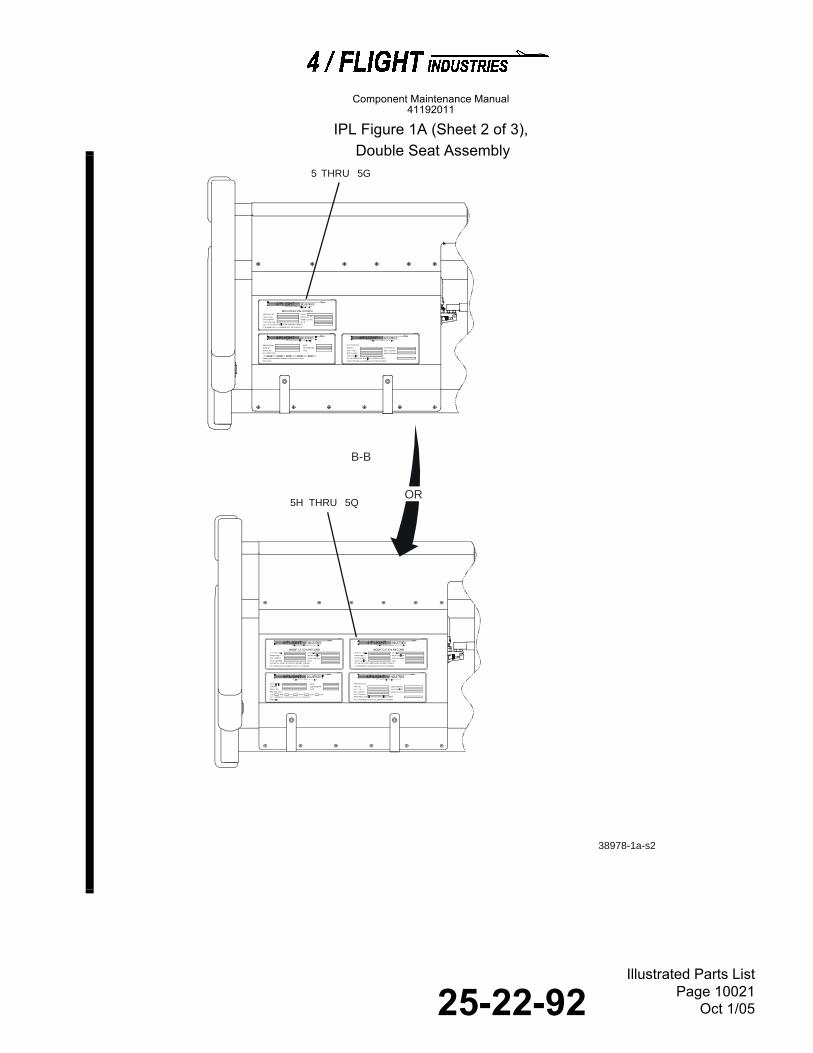
25-22-92Illustrated Parts List
Page 10021Oct 1/05
Component Maintenance Manual41192011
IPL Figure 1A (Sheet 2 of 3),
Double Seat Assembly
38978-1a-s2
B-B
OR
5 THRU 5G
5H THRU 5Q

25-22-92Illustrated Parts List
Page 10022Oct 1/05
Component Maintenance Manual41192011
IPL Figure 1A (Sheet 3 of 3),
Double Seat Assembly
38978-1a-s3
30
25 1520
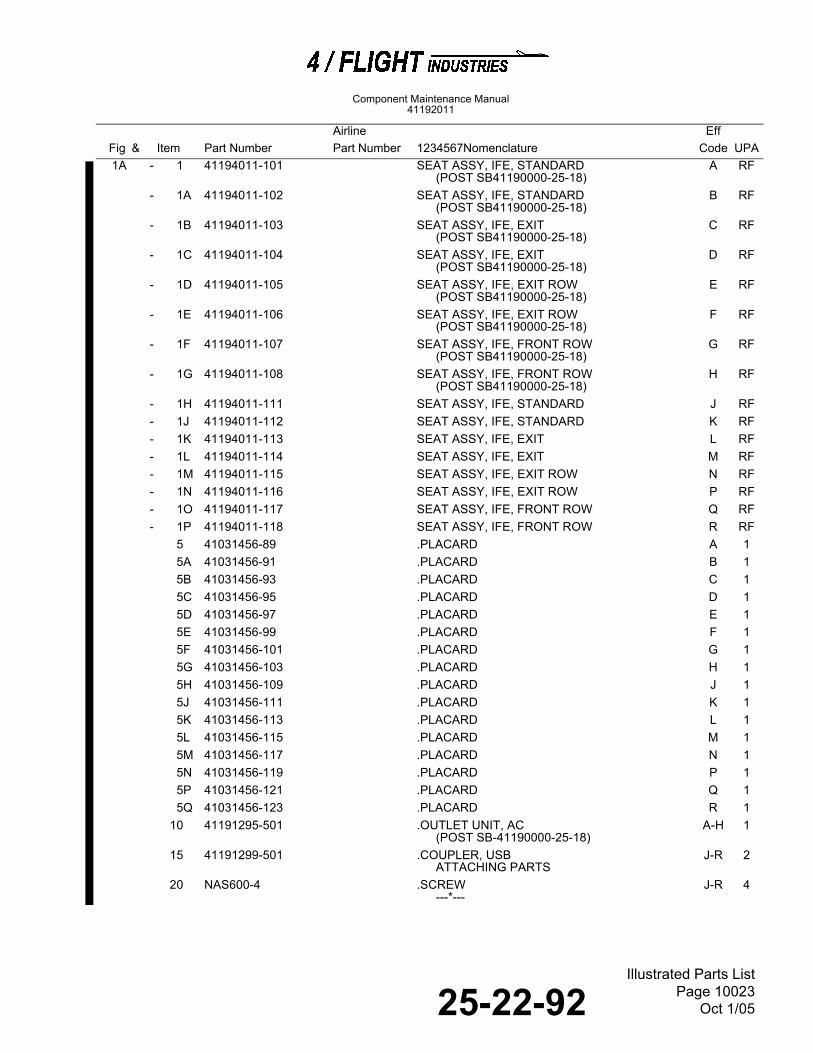
25-22-92Illustrated Parts List
Page 10023Oct 1/05
Component Maintenance Manual41192011
Airline Eff
Fig & Item Part Number Part Number 1234567Nomenclature Code UPA1A - 1 41194011-101 SEAT ASSY, IFE, STANDARD
(POST SB41190000-25-18)A RF
- 1A 41194011-102 SEAT ASSY, IFE, STANDARD(POST SB41190000-25-18)
B RF
- 1B 41194011-103 SEAT ASSY, IFE, EXIT(POST SB41190000-25-18)
C RF
- 1C 41194011-104 SEAT ASSY, IFE, EXIT(POST SB41190000-25-18)
D RF
- 1D 41194011-105 SEAT ASSY, IFE, EXIT ROW(POST SB41190000-25-18)
E RF
- 1E 41194011-106 SEAT ASSY, IFE, EXIT ROW(POST SB41190000-25-18)
F RF
- 1F 41194011-107 SEAT ASSY, IFE, FRONT ROW(POST SB41190000-25-18)
G RF
- 1G 41194011-108 SEAT ASSY, IFE, FRONT ROW(POST SB41190000-25-18)
H RF
- 1H 41194011-111 SEAT ASSY, IFE, STANDARD J RF- 1J 41194011-112 SEAT ASSY, IFE, STANDARD K RF- 1K 41194011-113 SEAT ASSY, IFE, EXIT L RF- 1L 41194011-114 SEAT ASSY, IFE, EXIT M RF- 1M 41194011-115 SEAT ASSY, IFE, EXIT ROW N RF- 1N 41194011-116 SEAT ASSY, IFE, EXIT ROW P RF- 1O 41194011-117 SEAT ASSY, IFE, FRONT ROW Q RF- 1P 41194011-118 SEAT ASSY, IFE, FRONT ROW R RF
5 41031456-89 .PLACARD A 15A 41031456-91 .PLACARD B 15B 41031456-93 .PLACARD C 15C 41031456-95 .PLACARD D 15D 41031456-97 .PLACARD E 15E 41031456-99 .PLACARD F 15F 41031456-101 .PLACARD G 15G 41031456-103 .PLACARD H 15H 41031456-109 .PLACARD J 15J 41031456-111 .PLACARD K 15K 41031456-113 .PLACARD L 15L 41031456-115 .PLACARD M 15M 41031456-117 .PLACARD N 15N 41031456-119 .PLACARD P 15P 41031456-121 .PLACARD Q 15Q 41031456-123 .PLACARD R 1
10 41191295-501 .OUTLET UNIT, AC(POST SB-41190000-25-18)
A-H 1
15 41191299-501 .COUPLER, USBATTACHING PARTS
J-R 2
20 NAS600-4 .SCREW---*---
J-R 4

25-22-92Illustrated Parts List
Page 10024Oct 1/05
Component Maintenance Manual41192011
IPL Figure 2, Latch Shroud Assy
1A 25 41191301-501 .CABLE, USB J-P 230 41191300-501 .SVDU
ATTACHING PARTSJ-P 2
- 35 NAS601-5 .SCREW (RF IPL FIG. 3, ITEM 6)---*---
J-P 12
Airline EffFig & Item Part Number Part Number 1234567Nomenclature Code UPA
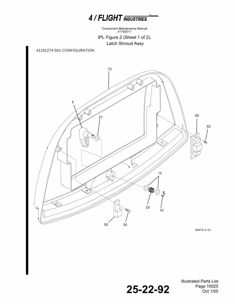
25-22-92Illustrated Parts List
Page 10025Oct 1/05
Component Maintenance Manual41192011
IPL Figure 2 (Sheet 1 of 2),
Latch Shroud Assy
41191274-501 CONFIGURATION
38978-2-S1

25-22-92Illustrated Parts List
Page 10026Oct 1/05
Component Maintenance Manual41192011
IPL Figure 2 (Sheet 2 of 2),
Latch Shroud Assy
41191274-503 AND 41191274-504 CONFIGURATIONS
38978-2-S2

25-22-92Illustrated Parts List
Page 10027Oct 1/05
Component Maintenance Manual41192011
IPL Figure 3, IFE Provisions Installation
Airline EffFig & Item Part Number Part Number 1234567Nomenclature Code UPA
2 - 1 41191274-501 SHROUD ASSY, MONITOR(RF IPL FIG. 1 FOR NHA)
A RF
- 1A 41191274-503 SHROUD ASSY, MONITOR, EXIT ROW(RF IPL FIG. 1 FOR NHA)
B RF
- 1B 41191274-504 SHROUD ASSY, MONITOR, EXIT ROW(RF IPL FIG. 1 FOR NHA)
C RF
5 41191060-505 .LATCH ASSY, FOODTRAY(SUPSD BY ITEM -5A)
1
- 5A 41191161-503 .LATCH ASSY, FOODTRAY(SUPSDS ITEM 5)ATTACHING PARTS
1
10 MS24665-151 .PIN, COTTER A 1- 10A MS171498 .PIN, SPRING BC 1
15 AN960C416 .WASHER (ALT FOR ITEM 15) A 2- 15A AN960C416 .WASHER (ALT FOR ITEM -15A) BC 1- 15B NAS1149C0463R .WASHER A 2- 15C NAS1149C0463R .WASHER BC 1
20 LC032E1 .SPRING, COMPRESSION (V84830) 121 5606-12-40 .WASHER, NYLON (V86928)
---*---1
25 41191151-1 .STOP, LATCH(SUPSD BY ITEM -25A)
BC 1
- 25A 41191169-1 .STOP, LATCH(SUPSDS ITEM 25)
BC 1
26 41191169-3 .STOP, LATCH BC 127 41351090-503 .STOP, LATCH
ATTACHING PARTSBC 1
30 5606-12-40 DELETED35 41191212-1 DELETED 140 NAS603-4 .SCREW BC 145 NAS1149F0332P .WASHER BC 1
- 45A AN960-10L .WASHER (ALT)---*---
BC 1
50 41191287-501 .SHROUD ATTACHMENT, MONITORATTACHING PARTS
2
55 NAS514P832-7 .SCREW---*---
2
60 41191299-501 .COUPLER, USB(RF IPL FIG. 1A, ITEM 15)ATTACHING PARTS
1
65 NAS600-4 .SCREW(RF IPL FIG. 1A, ITEM 20)---*---
1
70 41191273-501 .SHROUD, MONITOR A 1- 70A 41191273-503 .SHROUD, MONITOR, EXIT B 1- 70B 41191273-504 .SHROUD, MONITOR, EXIT C 1

25-22-92Illustrated Parts List
Page 10028Oct 1/05
Component Maintenance Manual41192011
IPL Figure 3 (Sheet 1 of 3), IFE Provisions Installation
100
38978-3-s1
51
100
55
60
65
67
68
6666
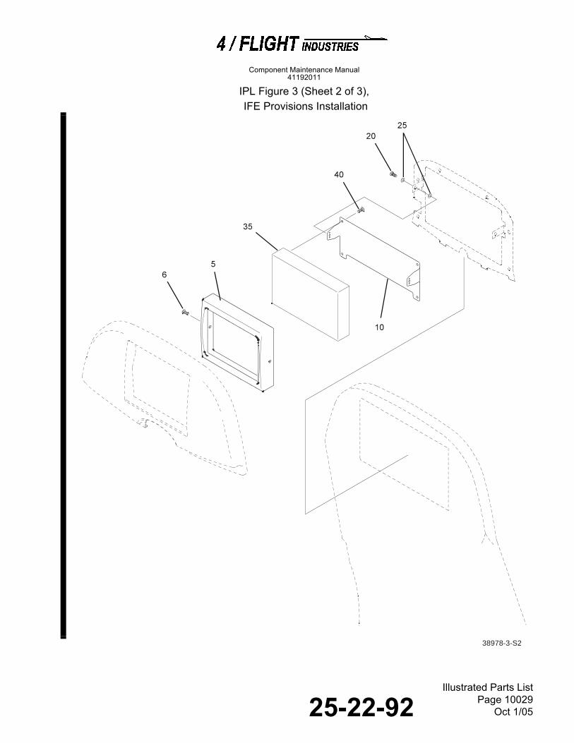
25-22-92Illustrated Parts List
Page 10029Oct 1/05
Component Maintenance Manual41192011
IPL Figure 3 (Sheet 2 of 3), IFE Provisions Installation
38978-3-S2
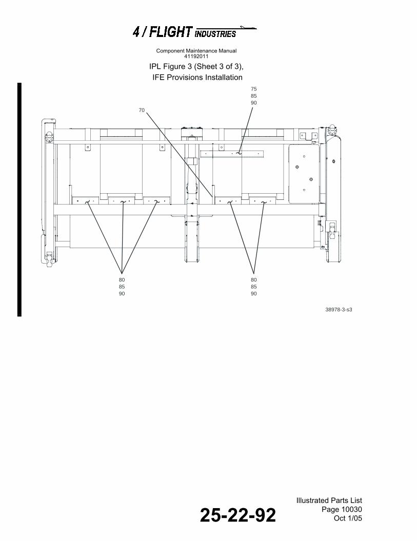
25-22-92Illustrated Parts List
Page 10030Oct 1/05
Component Maintenance Manual41192011
IPL Figure 3 (Sheet 3 of 3), IFE Provisions Installation
38978-3-s3
758590
808590
808590
70

25-22-92Illustrated Parts List
Page 10031Oct 1/05
Component Maintenance Manual41192011
Airline Eff
Fig & Item Part Number Part Number 1234567Nomenclature Code UPA3 - 1 41191290-501 INSTALLATION, IFE PROVISIONS, STD
(RF IPL FIG. 1 FOR NHA)A RF
- 1A 41191290-502 INSTALLATION, IFE PROVISIONS, STD(RF IPL FIG. 1 FOR NHA)
B RF
- 1B 41191290-503 INSTALLATION, IFE PROVISIONS, LAST ROW(RF IPL FIG. 1 FOR NHA)
C RF
- 1C 41191290-504 INSTALLATION, IFE PROVISIONS, LAST ROW(RF IPL FIG. 1 FOR NHA)
D RF
5 41191280-1 .BEZEL, MONITORATTACHING PARTS
2
6 NAS601-5 .SCREW---*---
4
10 41191282-501 .BRACKET ASSY, MONITORATTACHING PARTS
2
15 41191203-1 DELETED20 NAS601-6 .SCREW 425 90295A080 .WASHER, NYLON (V3A054)
---*---8
30 41191202-501 DELETED35 41191296-501 .MONITOR, DUMMY
ATTACHING PARTS2
40 NAS601-5 .SCREW---*---
8
45 NAS601-6 DELETED50 90295A080 DELETED51 MS21266-2N .GROMMET, PLASTIC, EDGING AR55 41191288-1 .COVER, INTERFACE BRACKET
ATTACHING PARTS1
60 NAS1096-3-6 .BOLT 265 AN960-10L .WASHER (ALT) 2
- 65A NAS1149F0332P .WASHER ---*---
2
66 MS21266-1N .GROMMET, PLASTIC, EDGING AR67 41191289-501 .BRACKET ASSY, INTERFACE
ATTACHING PARTS1
68 SD42BS .RIVET, POP (V01556)---*---
4
70 8507K52 .GROMMET, EDGE (V3A054) AR75 41191263-1 .RACEWAY, CABLE
(SUPSD BY ITEM -75A)1
- 75A 41191263-5 .RACEWAY, CABLE, 9.00 INCHES LONG(SUPSDS ITEM 75)
1
80 41191263-3 .RACEWAY, CABLE(SUPSD BY ITEMS -80A AND -80B)
2
- 80A 41191263-3 .RACEWAY, CABLE, 3.75 INCHES LONG(SUPSDS ITEM 80)
AB 5
- 80B 41191263-3 .RACEWAY, CABLE, 3.75 INCHES LONG(SUPSDS ITEM 80)ATTACHING PARTS
CD 2
85 SD43BS .RIVET, POP (V01556) AB 13

25-22-92Illustrated Parts List
Page 10032Oct 1/05
Component Maintenance Manual41192011
3 - 85A SD43BS .RIVET, POP (V01556) CD 7
90 NAS1149FN616P .WASHER AB 13- 90A NAS1149FN616P .WASHER CD 7- 90B AN960-6L .WASHER
(ALT FOR ITEM 95)AB 13
- 90C AN960-6L .WASHER(ALT FOR ITEM -95A)---*---
CD 7
95 41191222-501-8 DELETED100 41191222-501-17 .CONDUIT, VELCRO, 17 INCH AB 2
Airline EffFig & Item Part Number Part Number 1234567Nomenclature Code UPA

25-22-92Illustrated Parts List
Page 10033Oct 1/05
Component Maintenance Manual41192011
THIS PAGE IS INTENTIONALLY LEFT BLANK

25-22-92Illustrated Parts List
Page 10034Oct 1/05
Component Maintenance Manual41192011
IPL Figure 4, Wiring Harness Installation IPL Figure 4 (Sheet 1 of 3),
Wiring Harness Installation
38978-4-s1
1515
4055
4055
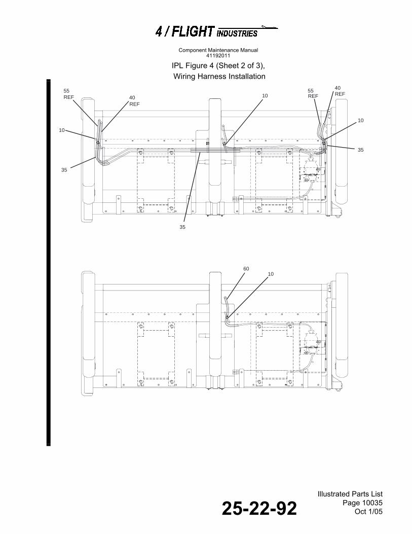
25-22-92Illustrated Parts List
Page 10035Oct 1/05
Component Maintenance Manual41192011
IPL Figure 4 (Sheet 2 of 3), Wiring Harness Installation
38978-4-s2
55 40
35
35
10
40
35
6010
10
REFREF
REF55REF
10

25-22-92Illustrated Parts List
Page 10036Oct 1/05
Component Maintenance Manual41192011
IPL Figure 4 (Sheet 3 of 3), Wiring Harness Installation
38978-4-s3
67 (OPP )
35
202530

25-22-92Illustrated Parts List
Page 10037Oct 1/05
Component Maintenance Manual41192011
IPL Figure 5, Monitor Bracket Assembly
Airline EffFig & Item Part Number Part Number 1234567Nomenclature Code UPA
4 - 1 41191285-501 INSTALLATION, WIRING HARNESS, STD(RF IPL FIG. 1 FOR NHA)
A RF
- 1A 41191285-502 INSTALLATION, WIRING HARNESS, STD(RF IPL FIG. 1 FOR NHA)
B RF
- 1B 41191285-505 INSTALLATION, WIRING HARNESS, STD(RF IPL FIG. 1 FOR NHA)(SUPSD BY ITEM 1D)
C RF
- 1C 41191285-506 INSTALLATION, WIRING HARNESS, STD(RF IPL FIG. 1 FOR NHA)(SUPSD BY ITEM 1E)
D RF
- 1D 41191285-503 INSTALLATION, WIRING HARNESS, LAST ROW(RF IPL FIG. 1 FOR NHA)(SUPSDS ITEM 1B)
E RF
- 1E 41191285-504 INSTALLATION, WIRING HARNESS, LAST ROW(RF IPL FIG. 1 FOR NHA)(SUPSDS ITEM 1C)
F RF
5 41191223-501 DELETED6 41191298-501 .JACK ASSY, AUDIO 17 41191298-502 .JACK ASSY, AUDIO 1
10 PLT3SM .TIE, CABLE (V06383) AB 4- 10A PLT3SM .TIE, CABLE (V06383) EF 1
15 PLT1.5M .TIE, CABLE (V06383) AB 220 MS25281F6 .CLAMP, CABLE
ATTACHING PARTS1
25 NAS603-21 .SCREW---*---
1
30 41191291-1 .SPACER, STANDOFF 135 5676000507 .WRAP, CABLE (V4V852) AR40 A127011-501 .CABLE ASSY, VDU/VDU JUMPER (V56135) AB 145 A127015-501 DELETED50 41191301-501 DELETED55 A127012-501 .CABLE ASSY, IFE (V56135) AB 160 A127013-501 .CABLE ASSY, AUDIO ONLY, LAST ROW
(V56135)EF 1

25-22-92Illustrated Parts List
Page 10038Oct 1/05
Component Maintenance Manual41192011
IPL Figure 5, Monitor Bracket Assembly
DELETED

25-22-92Illustrated Parts List
Page 10039Oct 1/05
Component Maintenance Manual41192011
IPL Figure 5A, Power Port Installation
Airline EffFig & Item Part Number Part Number 1234567Nomenclature Code UPA
5 - 1 41191202-501 DELETED5 41191255-501 DELETED
10 41191255-502 DELETED15 NAS514P632-3 DELETED20 5133-9 DELETED25 41191255-3 DELETED30 B56 DELETED35 358506CNY207 DELETED40 41191255-1 DELETED
- 40A 41191255-2 DELETED45 PFSC35-38A DELETED50 41191202-1 DELETED

25-22-92Illustrated Parts List
Page 10040Oct 1/05
Component Maintenance Manual41192011
IPL Figure 5A, Power Port Installation
38978-5
60
70
5 1510
20
25
30
35
404550
55
75
65
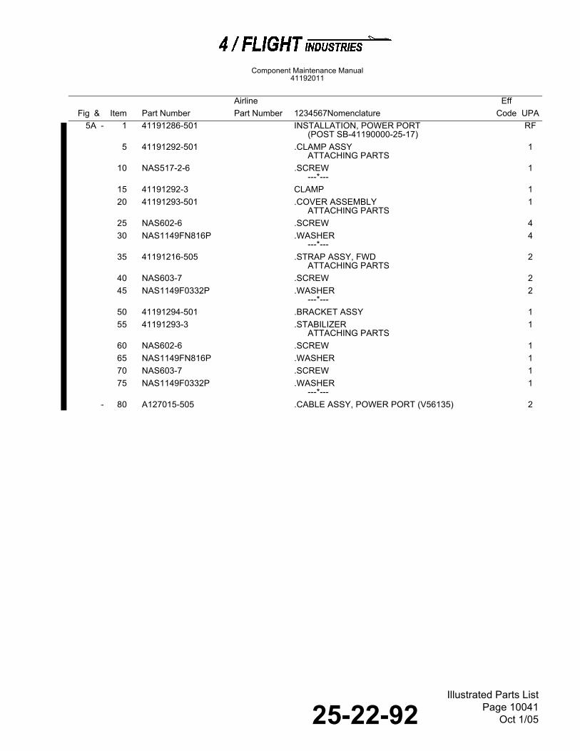
25-22-92Illustrated Parts List
Page 10041Oct 1/05
Component Maintenance Manual41192011
IPL Figure 6, Sliding Foodtray Assembly
Airline EffFig & Item Part Number Part Number 1234567Nomenclature Code UPA
5A - 1 41191286-501 INSTALLATION, POWER PORT(POST SB-41190000-25-17)
RF
5 41191292-501 .CLAMP ASSYATTACHING PARTS
1
10 NAS517-2-6 .SCREW---*---
1
15 41191292-3 CLAMP 120 41191293-501 .COVER ASSEMBLY
ATTACHING PARTS1
25 NAS602-6 .SCREW 430 NAS1149FN816P .WASHER
---*---4
35 41191216-505 .STRAP ASSY, FWDATTACHING PARTS
2
40 NAS603-7 .SCREW 245 NAS1149F0332P .WASHER
---*---2
50 41191294-501 .BRACKET ASSY 155 41191293-3 .STABILIZER
ATTACHING PARTS1
60 NAS602-6 .SCREW 165 NAS1149FN816P .WASHER 170 NAS603-7 .SCREW 175 NAS1149F0332P .WASHER
---*---1
- 80 A127015-505 .CABLE ASSY, POWER PORT (V56135) 2

25-22-92Illustrated Parts List
Page 10042Oct 1/05
Component Maintenance Manual41192011
IPL Figure 6, Sliding Foodtray Assembly
38943-4
5
10
25
20
15
30

25-22-92Illustrated Parts List
Page 10043Oct 1/05
Component Maintenance Manual41192011
IPL Figure 7, Double Seat Structure Assembly
Airline EffFig & Item Part Number Part Number 1234567Nomenclature Code UPA
6 - 1 41191227-503 FOODTRAY ASSY, SLIDING(RF IPL FIG. 1 FOR NHA)
RF
5 41351085-7 .CROSSTUBEATTACHING PARTS
1
10 NAS514P1032-8 .SCREW---*---
2
15 41351088-503 .STOP ASSY, FOODTABLEATTACHING PARTS
2
20 41031081-1 .PIN, PIVOT---*---
2
25 41031037-5 .STUD 230 41191227-601 .FOODTABLE ASSY
(SUPSD BY ITEM -30A)1
- 30A 41191227-603 .FOODTABLE ASSY(SUPSDS ITEM 30)
1

25-22-92Illustrated Parts List
Page 10044Oct 1/05
Component Maintenance Manual41192011
IPL Figure 7 (Sheet 1 of 3),
Double Seat Structure Assembly
38978-7-s1
95100
5
10
15
2025
260
275255
265
315
305
310
300
A
SEE
B
SEE
85
240
245
250
270
225
230
3035
320
90
295
290
290
285
280
180
195200
205
210
215
220
185
190
235
225230

25-22-92Illustrated Parts List
Page 10045Oct 1/05
Component Maintenance Manual41192011
IPL Figure 7 (Sheet 2 of 3),
Double Seat Structure Assembly
38978-7-s2
4575
80
75
70
65
45
A
40
6055
5550

25-22-92Illustrated Parts List
Page 10046Oct 1/05
Component Maintenance Manual41192011
IPL Figure 7 (Sheet 3 of 3),
Double Seat Structure Assembly
145
130
155
140
135105110 ( OPP )
115
120
125
38978-7-s3
140
B
160175
165170
B
150

25-22-92Illustrated Parts List
Page 10047Oct 1/05
Component Maintenance Manual41192011
Airline Eff
Fig & Item Part Number Part Number 1234567Nomenclature Code UPA7 - 1 41191270-501 STRUCTURE ASSY, DOUBLE SEAT
(RF IPL FIG. 1 FOR NHA)A RF
- 1A 41191270-502 STRUCTURE ASSY, DOUBLE SEAT (RF IPL FIG. 1 FOR NHA)
B RF
- 1B 41191270-503 STRUCTURE ASSY, DOUBLE SEAT (RF IPL FIG. 1 FOR NHA)
C RF
- 1C 41191270-504 STRUCTURE ASSY, DOUBLE SEAT (RF IPL FIG. 1 FOR NHA)
D RF
- 1D 41191270-505 STRUCTURE ASSY, DOUBLE SEAT (RF IPL FIG. 1 FOR NHA)
E RF
- 1E 41191270-506 STRUCTURE ASSY, DOUBLE SEAT (RF IPL FIG. 1 FOR NHA)
F RF
- 1F 41191270-507 STRUCTURE ASSY, DOUBLE SEAT (RF IPL FIG. 1 FOR NHA)
G RF
- 1G 41191270-508 STRUCTURE ASSY, DOUBLE SEAT (RF IPL FIG. 1 FOR NHA)
H RF
5 41191022-505 .CART BUMPER, UPPER ACEG
1
- 5A 41191022-506 .CART BUMPER, UPPERATTACHING PARTS
BDFH 1
10 NAS602-7 .SCREW 315 NAS1149FN832P .WASHER
(SUPSD BY ITEM -15B)3
- 15A AN960-8 .WASHER (ALT)(SUPSD BY ITEM -15C)
3
- 15B NAS1149FN816P .WASHER(SUPSDS ITEM 15)
3
- 15C AN960-8L .WASHER (ALT)(SUPSDS ITEM -15A)---*---
3
20 41191021-505 .CART BUMPER, LOWER ACEG
1
- 20A 41191021-506 .CART BUMPER, LOWERATTACHING PARTS
BDFH 1
25 NAS1352-08-8 .SCREW, CAP 130 NAS602-7 .SCREW 535 AN960-8 .WASHER (ALT)
(SUPSD BY ITEM -35B)5
- 35A NAS1149FN832P .WASHER (SUPSD BY ITEM -35C)
5
- 35B NAS1149FN816P .WASHER(SUPSDS ITEM 35)
5
- 35C AN960-8L .WASHER (ALT)(SUPSDS ITEM -35A)---*---
5
40 PLT2SM .TIE, CABLE (V06383) ABE-H
2
45 41031056-501 .LOCK, HYDRAULIC (V0001)MN08.1.0169(SUPSD BY ITEM -45A)
2
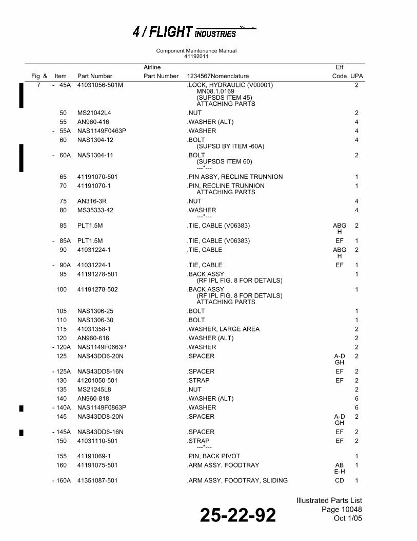
25-22-92Illustrated Parts List
Page 10048Oct 1/05
Component Maintenance Manual41192011
7 - 45A 41031056-501M .LOCK, HYDRAULIC (V00001)
MN08.1.0169(SUPSDS ITEM 45)ATTACHING PARTS
2
50 MS21042L4 .NUT 255 AN960-416 .WASHER (ALT) 4
- 55A NAS1149F0463P .WASHER 460 NAS1304-12 .BOLT
(SUPSD BY ITEM -60A)4
- 60A NAS1304-11 .BOLT(SUPSDS ITEM 60)---*---
2
65 41191070-501 .PIN ASSY, RECLINE TRUNNION 170 41191070-1 .PIN, RECLINE TRUNNION
ATTACHING PARTS1
75 AN316-3R .NUT 480 MS35333-42 .WASHER
---*---4
85 PLT1.5M .TIE, CABLE (V06383) ABGH
2
- 85A PLT1.5M .TIE, CABLE (V06383) EF 190 41031224-1 .TIE, CABLE ABG
H2
- 90A 41031224-1 .TIE, CABLE EF 195 41191278-501 .BACK ASSY
(RF IPL FIG. 8 FOR DETAILS)1
100 41191278-502 .BACK ASSY(RF IPL FIG. 8 FOR DETAILS)ATTACHING PARTS
1
105 NAS1306-25 .BOLT 1110 NAS1306-30 .BOLT 1115 41031358-1 .WASHER, LARGE AREA 2120 AN960-616 .WASHER (ALT) 2
- 120A NAS1149F0663P .WASHER 2125 NAS43DD6-20N .SPACER A-D
GH2
- 125A NAS43DD8-16N .SPACER EF 2130 41201050-501 .STRAP EF 2135 MS21245L8 .NUT 2140 AN960-818 .WASHER (ALT) 6
- 140A NAS1149F0863P .WASHER 6145 NAS43DD8-20N .SPACER A-D
GH2
- 145A NAS43DD6-16N .SPACER EF 2150 41031110-501 .STRAP
---*---EF 2
155 41191069-1 .PIN, BACK PIVOT 1160 41191075-501 .ARM ASSY, FOODTRAY AB
E-H1
- 160A 41351087-501 .ARM ASSY, FOODTRAY, SLIDING CD 1
Airline EffFig & Item Part Number Part Number 1234567Nomenclature Code UPA

25-22-92Illustrated Parts List
Page 10049Oct 1/05
Component Maintenance Manual41192011
7 165 41191075-502 .ARM ASSY, FOODTRAY AB
E-H1
- 165A 41351087-502 .ARM ASSY, FOODTRAY, SLIDING CD 1170 41191075-503 .ARM ASSY, FOODTRAY AB
E-H1
- 170A 41351087-503 .ARM ASSY, FOODTRAY, SLIDING CD 1175 41191075-504 .ARM ASSY, FOODTRAY AB
D-H1
- 175A 41351087-504 .ARM ASSY, FOODTRAY, SLIDING CD 1180 41191272-503 .BACK PLATE, FRONT
ATTACHING PARTS2
185 NAS602-6 .SCREW(SUPSD BY ITEM -185A)
12
- 185A NAS602-5 .SCREW(SUPSDS ITEM 185)
12
190 AN960-8 .WASHER (ALT)(SUPSD BY ITEM -195C)
12
- 190A NAS1149FN832P .WASHER (SUPSD BY ITEM -195B)
12
- 190B NAS1149FN816P .WASHER(SUPSDS ITEM 195)
12
- 190C AN960-8 .WASHER (ALT)(SUPSDS ITEM -195A)---*---
12
195 41191287-3 .ATTACHMENT SHROUDATTACHING PARTS
4
200 NAS602-8 .SCREW 4205 AN960-8 .WASHER (ALT)
(SUPSD BY ITEM -205C)4
- 205A NAS1149FN832P .WASHER(SUPSD BY ITEM -205B)
4
- 205B NAS1149FN816P .WASHER (SUPSDS ITEM 205)
4
- 205C AN960-8L .WASHER (ALT)(SUPSDS ITEM -205A)---*---
4
210 41191272-501 .PLATE ASSY, BACKATTACHING PARTS
2
215 NAS602-6 .SCREW(SUPSD BY ITEM 215A)
4
- 215A NAS602-5 .SCREW(SUPSDS ITEM 215)
4
220 AN960-8 .WASHER (ALT)(SUPSD BY ITEM -220C)
4
- 220A NAS1149FN832P .WASHER (SUPSD BY ITEM -220B)
4
- 220B NAS1149FN816P .WASHER(SUPSDS ITEM 220)
4
- 220C AN960-8L .WASHER (ALT)(SUPSDS ITEM -220A)---*---
4
225 MS25281F4 .CLAMP, CABLE ABGH
2
Airline EffFig & Item Part Number Part Number 1234567Nomenclature Code UPA

25-22-92Illustrated Parts List
Page 10050Oct 1/05
Component Maintenance Manual41192011
7 225A MS25281F4 .CLAMP, CABLE
ATTACHING PARTSEF 1
230 NAS603-6 .SCREW ABGH
2
- 230A NAS603-6 .SCREW---*---
EF 1
235 41191080-541 .ARMREST ASSY(RF IPL FIG. 8A FOR DETAILS)
AEG 1
- 235A 41191080-542 .ARMREST ASSY(RF IPL FIG. 8A FOR DETAILS)
BFH 1
- 235B 41191080-557 .ARMREST ASSY, NO RECLINE, LATCH PIN(RF IPL FIG. 8A FOR DETAILS)ATTACHING PARTS
CD 1
- 235C 41191210-517 DELETED- 235D 41191210-518 DELETED
240 5133-25 .RING, RETAINING (V79136) 1245 5806-126-3 .WASHER, WAVE (V86928) 2250 41191033-1 .PIN
---*---1
255 41191090-1 .MODULE, PLUNGERATTACHING PARTS
1
260 NAS514P1032-5 .SCREW---*---
1
265 41191034-1 .PLUNGERATTACHING PARTS
1
270 NAS1081-04A4P .SETSCREW---*---
1
275 LC026C1 .SPRING (V84830) 1280 41191080-546 .ARMREST ASSY, LOCKDOWN BOLT
(RF IPL FIG. 8A FOR DETAILS)AG 1
- 280A 41191080-545 .ARMREST ASSY, LOCKDOWN BOLT(RF IPL FIG. 8A FOR DETAILS)
BH 1
- 280B 41191080-559 .ARMREST ASSY, NO RECLINE, LOCKDOWN BOLT(RF IPL FIG. 8A FOR DETAILS)
CD 1
- 280C 41191240-501 .ARMREST ASSY, STUB, EXIT OUTBDATTACHING PARTS
EF 1
285 5133-25 .RING, RETAINING (V79136) 1290 5806-126-3 .WASHER, WAVE (V86928) 2295 41191033-1 .PIN
---*---1
300 41191210-521 .ARMREST ASSY, CENTER(RF IPL FIG. 9 FOR DETAILS
A-DGH
1
- 300A 41191210-519 .ARMREST ASSY, RECLINE, EXIT, CENTER(RF IPL FIG. 9 FOR DETAILS)
E 1
- 300B 41191210-520 .ARMREST ASSY, RECLINE, EXIT, CENTER(RF IPL FIG. 9 FOR DETAILS)ATTACHING PARTS
F 1
305 5133-25 .RING, RETAINING (V79136) 1310 5806-126-3 .WASHER, WAVE (V86928) 2
- 310A NAS1149F0432P .WASHER 2
Airline EffFig & Item Part Number Part Number 1234567Nomenclature Code UPA

25-22-92Illustrated Parts List
Page 10051Oct 1/05
Component Maintenance Manual41192011
IPL Figure 8, Back Structure Assembly
7 - 310B AN960-416L .WASHER (ALT) 2315 41191033-1 .PIN
---*---1
320 41191205-501 .FRAME ASSY, BASE(SUPSD BY ITEM -320F)(RF IPL FIG. 10 FOR DETAILS)
AC 1
- 320A 41191205-502 .FRAME ASSY, BASE(SUPSD BY ITEM -320G)(RF IPL FIG. 10 FOR DETAILS)
BD 1
- 320B 41191205-505 .FRAME ASSY, BASE, EXIT ROW(SUPSD BY ITEM -320H)(RF IPL FIG. 10 FOR DETAILS)
E 1
- 320C 41191205-506 .FRAME ASSY, BASE, EXIT ROW(SUPSD BY ITEM -320J)(RF IPL FIG. 10 FOR DETAILS)
F 1
- 320D 41191205-503 .FRAME ASSY, BASE, LAST ROW(SUPSD BY ITEM -320K)(RF IPL FIG. 10 FOR DETAILS)
G 1
- 320E 41191205-504 .FRAME ASSY, BASE, LAST ROW(SUPSD BY ITEM -320L)(RF IPL FIG. 10 FOR DETAILS)
H 1
- 320F 41191205-513 .FRAME ASSY, BASE(SUPSDS ITEM 320)(RF IPL FIG. 10 FOR DETAILS)
AC 1
- 320G 41191205-514 .FRAME ASSY, BASE(SUPSDS ITEM -320A)(RF IPL FIG. 10 FOR DETAILS
BD 1
- 320H 41191205-515 .FRAME ASSY, BASE, EXIT ROW(SUPSDS ITEM -320B)(RF IPL FIG. 10 FOR DETAILS
E 1
- 320J 41191205-516 .FRAME ASSY, BASE, EXIT ROW(SUPSDS ITEM -320C)(RF IPL FIG. 10 FOR DETAILS
F 1
- 320K 41191205-507 .FRAME ASSY, BASE, LAST ROW(SUPSDS ITEM -320D)(RF IPL FIG. 10 FOR DETAILS
G 1
- 320L 41191205-508 .FRAME ASSY, BASE, LAST ROW(SUPSDS ITEM -320E)(RF IPL FIG. 10 FOR DETAILS
H 1
Airline EffFig & Item Part Number Part Number 1234567Nomenclature Code UPA

25-22-92Illustrated Parts List
Page 10052Oct 1/05
Component Maintenance Manual41192011
IPL Figure 8, Back Structure Assembly
38978-8
90
65
15
5
55
60
20
105
10
25
70
95
75
80
85
30354045
4050
100
110115
116120

25-22-92Illustrated Parts List
Page 10053Oct 1/05
Component Maintenance Manual41192011
Airline Eff
Fig & Item Part Number Part Number 1234567Nomenclature Code UPA8 - 1 41191278-501 BACK ASSY
(RF IPL FIG. 7 FOR NHA)A RF
- 1A 41191278-502 BACK ASSY(RF IPL FIG. 7 FOR NHA)
B RF
5 41191258-501 .QUADRANT ASSY, EASATTACHING PARTS
1
10 NAS6604-1 .BOLT(SUPSD BY ITEM -10A)
1
- 10A NAS6604L1 .BOLT(SUPSDS ITEM 10)---*---
1
15 41191260-1 .PLUG 120 41191261-1 .BUSHING 125 41191259-501 .FITTING ASSY, BACK PIVOT A 1
- 25A 41191259-502 .FITTING ASSY, BACK PIVOTATTACHING PARTS
B 1
30 MS21042L3 .NUT 235 NAS1149F0332P .WASHER 240 CDSP5801-3AL .WASHER (V56135) 445 MS24694C51 .SCREW 250 NAS514P1032-7 .SCREW
---*---2
55 NAS75-8-013 .BUSHING 160 NAS76A6-006 .BUSHING 165 TYE2161-3-7 .INSERT (V56958) 270 TYE2161-08-100 .INSERT (V56958)
(SUPSD BY ITEM -70A)8
- 70A TYE2168-08-1000 .INSERT (V56135)(SUPSDS ITEM 70)
6
75 BS18303-3A .STUD, DIRECTIONAL (V3DCM5)ATTACHING PARTS
2
80 1693-0414 .RIVET (V0EV66) 285 NAS620-5L .WASHER
---*---2
90 4FSP0002-59 .VELCRO, 2.00 INCH, FOSSIL, LOOP AR95 4FSP0002-57 .VELCRO, 1.00 INCH, FOSSIL, LOOP AR
100 4FSP0002-53 .VELCRO, 2.00 INCH, FOSSIL, HOOK AR105 4FSP0002-51 .VELCRO, 1.00 INCH, FOSSIL, HOOK AR110 41191278-3 .PAD 1115 41191278-5 .PAD 1116 41191278-1 .EDGEFILL AR120 41191209-501 .STRUCTURE ASSY, BACK (NP)
(SUPSD BY ITEM -120B)A 1
- 120A 41191209-502 .STRUCTURE ASSY, BACK (NP)(SUPSD BY ITEM -120C)
B 1
- 120B 41191279-501 .STRUCTURE ASSY, BACK (NP)(SUPSDS ITEM 120)
A 1
- 120C 41191279-502 .STRUCTURE ASSY, BACK (NP)(SUPSDS ITEM -120A)
B 1

25-22-92Illustrated Parts List
Page 10054Oct 1/05
Component Maintenance Manual41192011
THIS PAGE IS INTENTIONALLY LEFT BLANK
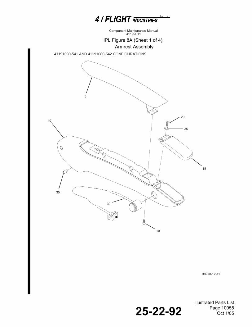
25-22-92Illustrated Parts List
Page 10055Oct 1/05
Component Maintenance Manual41192011
IPL Figure 8A, Armrest Assembly IPL Figure 8A (Sheet 1 of 4),
Armrest Assembly
38978-12-s1
15
20
25
5
40
10
35
30
41191080-541 AND 41191080-542 CONFIGURATIONS

25-22-92Illustrated Parts List
Page 10056Oct 1/05
Component Maintenance Manual41192011
IPL Figure 8A (Sheet 2 of 4),
Armrest Assembly
38978-12-s2
15
20
25
5
40
10
36
30
41191080-545 AND 41191080-546 CONFIGURATIONS
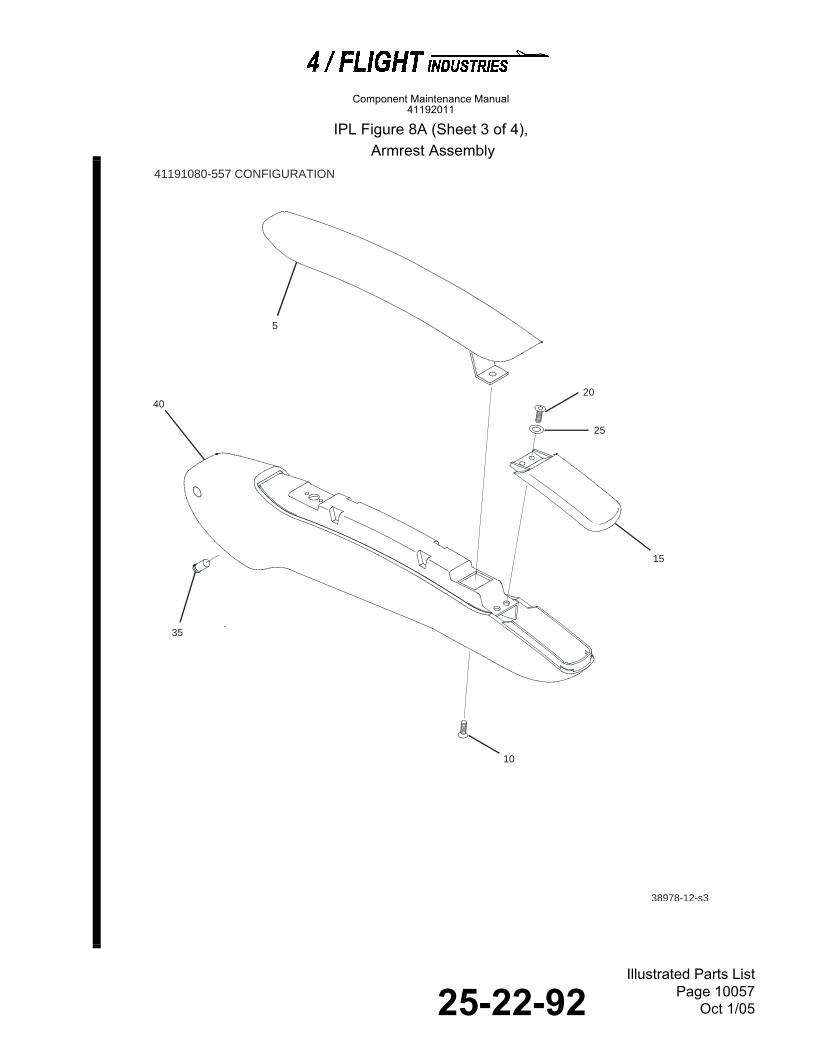
25-22-92Illustrated Parts List
Page 10057Oct 1/05
Component Maintenance Manual41192011
IPL Figure 8A (Sheet 3 of 4),
Armrest Assembly
38978-12-s3
15
20
25
5
40
10
41191080-557 CONFIGURATION
35
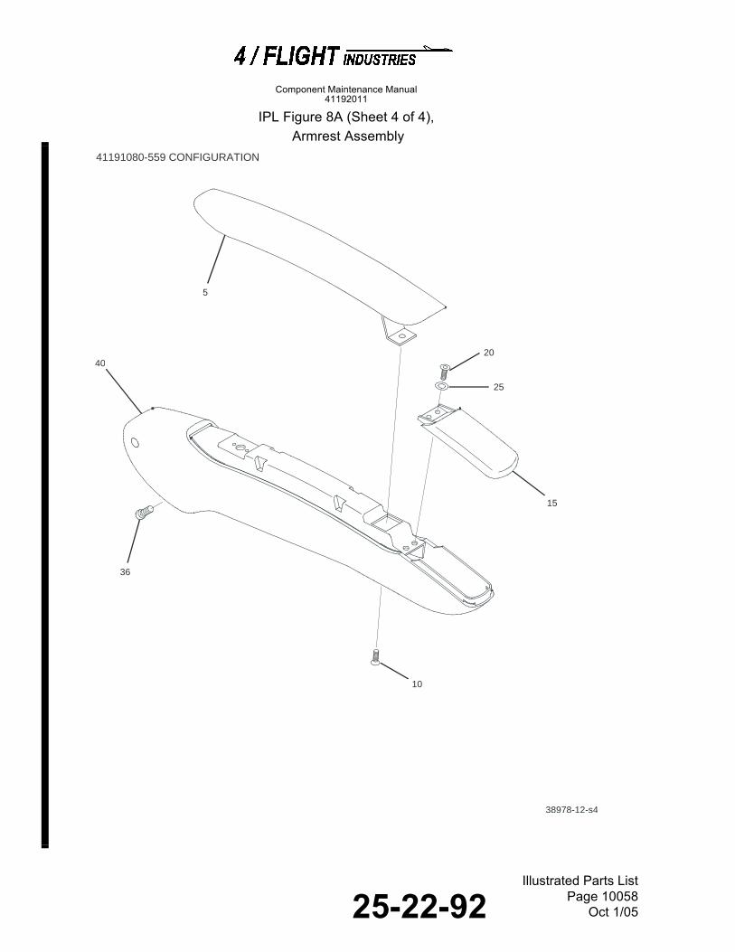
25-22-92Illustrated Parts List
Page 10058Oct 1/05
Component Maintenance Manual41192011
IPL Figure 8A (Sheet 4 of 4),
Armrest Assembly
38978-12-s4
15
20
25
5
40
10
36
41191080-559 CONFIGURATION
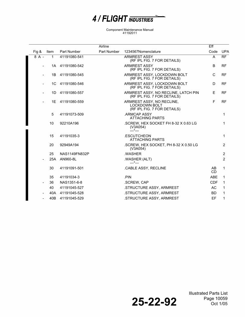
25-22-92Illustrated Parts List
Page 10059Oct 1/05
Component Maintenance Manual41192011
IPL Figure 9, Center Armrest Assembly
Airline EffFig & Item Part Number Part Number 1234567Nomenclature Code UPA8 A - 1 41191080-541 ARMREST ASSY
(RF IPL FIG. 7 FOR DETAILS)A RF
- 1A 41191080-542 ARMREST ASSY(RF IPL FIG. 7 FOR DETAILS)
B RF
- 1B 41191080-545 ARMREST ASSY, LOCKDOWN BOLT(RF IPL FIG. 7 FOR DETAILS)
C RF
- 1C 41191080-546 ARMREST ASSY, LOCKDOWN BOLT(RF IPL FIG. 7 FOR DETAILS)
D RF
- 1D 41191080-557 ARMREST ASSY, NO RECLINE, LATCH PIN(RF IPL FIG. 7 FOR DETAILS)
E RF
- 1E 41191080-559 ARMREST ASSY, NO RECLINE,LOCKDOWN BOLT(RF IPL FIG. 7 FOR DETAILS)
F RF
5 41191073-509 .ARMCAP ASSYATTACHING PARTS
1
10 92210A196 .SCREW, HEX SOCKET FH 8-32 X 0.63 LG (V3A054)---*---
1
15 41191035-3 .ESCUTCHEONATTACHING PARTS
1
20 92949A194 .SCREW, HEX SOCKET, PH 8-32 X 0.50 LG (V3A054)
2
25 NAS1149FN832P .WASHER 2- 25A AN960-8L .WASHER (ALT)
---*---2
30 41191091-501 .CABLE ASSY, RECLINE ABCD
1
35 41191034-3 .PIN ABE 1- 36 NAS1351-6-8 .SCREW, CAP CDF 1
40 41191045-527 .STRUCTURE ASSY, ARMREST AC 1- 40A 41191045-528 .STRUCTURE ASSY, ARMREST BD 1- 40B 41191045-529 .STRUCTURE ASSY, ARMREST EF 1

25-22-92Illustrated Parts List
Page 10060Oct 1/05
Component Maintenance Manual41192011
IPL Figure 9 (Sheet 1 of 3), Center Armrest Assembly
15
20
25
5
80
10
40A45
70
41191210-519 and 41191210-520 CONFIGURATIONS

25-22-92Illustrated Parts List
Page 10061Oct 1/05
Component Maintenance Manual41192011
IPL Figure 9 (Sheet 2 of 3), Center Armrest Assembly
65
60
50
55
41191210-519 AND 41191210-520 CONFIGURATIONS

25-22-92Illustrated Parts List
Page 10062Oct 1/05
Component Maintenance Manual41192011
IPL Figure 9 (Sheet 3 of 3), Center Armrest Assembly
38978-9-s3
15
20
25
5
80
10
41191210-521 CONFIGURATION

25-22-92Illustrated Parts List
Page 10063Oct 1/05
Component Maintenance Manual41192011
IPL Figure 10, Base Frame Assembly
Airline EffFig & Item Part Number Part Number 1234567Nomenclature Code UPA
9 - 1 41191210-517 DELETED- 1A 41191210-518 DELETED- 1B 41191210-519 ARMREST ASSY, RECLINE, EXIT, CENTER
(RF IPL FIG. 7 FOR NHA)A RF
- 1C 41191210-520 ARMREST ASSY, RECLINE, EXIT, CENTER(RF IPL FIG. 7 FOR NHA)
B RF
- 1D 41191210-521 ARMREST ASSY, NO RECLINE, EXIT, CENTER(RF IPL FIG. 7 FOR NHA)
C RF
5 41191073-509 .ARMCAP ASSYATTACHING PARTS
1
10 92210A194 .SCREW, HEX SOCKET, 8-32 X 0.50 LONG(V3A054)(SUPSD BY ITEM -10A)
1
- 10A 92210A196 .SCREW, HEX SOCKET, 8-32 X 0.62 LONG(V3A054)(SUPSDS ITEM 10)---*---
1
15 41191035-3 .ESCUTCHEONATTACHING PARTS
1
20 92249A194 .SCREW, HEX SOCKET, 8-32 X 0.50 LONG(V3A054)(SUPSD BY ITEM 20A)
2
- 20A 92949A194 .SCREW, HEX SOCKET, 8-32 X 0.50 LONG(V3A054)(SUPSDS ITEM 20)
2
25 AN960-8L .WASHER 2- 25A NAS1149FN816P .WASHER (ALT)
---*---2
30 41191217-7 DELETED35 NAS601-4 DELETED40 41191091-501 DELETED
- 40A MC71-32 .CABLE ASSY, RECLINE (V02953) 145 MC06685-00 ..INPUT ASSY (V02953) (NP) AB 150 MC03866-00 ...ESCUTCHEON (V02953) AB 155 CA01031-00 ...WASHER, WAVE SPRING (V02953) AB 160 MC04685-70 ...SUPPORT ASSY (V02953) (NP) AB 165 MS16632-2025 ..RING, CLIP (V02953) (NP) AB 170 MC90251-00 ..OUTPUT ASSY (V02953) (NP) AB 175 41191034-3 DELETED80 41191030-507 .STRUCTURE ASSY, ARMREST
(SUPSD BY ITEMS -80B AND -80D)AC 1
- 80A 41191030-508 .STRUCTURE ASSY, ARMREST(SUPSD BY ITEM -80C)
BD 1
- 80B 41191230-507 .STRUCTURE ASSY, ARMREST(SUPSDS ITEM 80)
A 1
- 80C 41191230-508 .STRUCTURE ASSY, ARMREST(SUPSDS ITEM -80B)
B 1
- 80D 41191230-505 .STRUCTURE ASSY, ARMREST(SUPSDS ITEM 80)
C 1
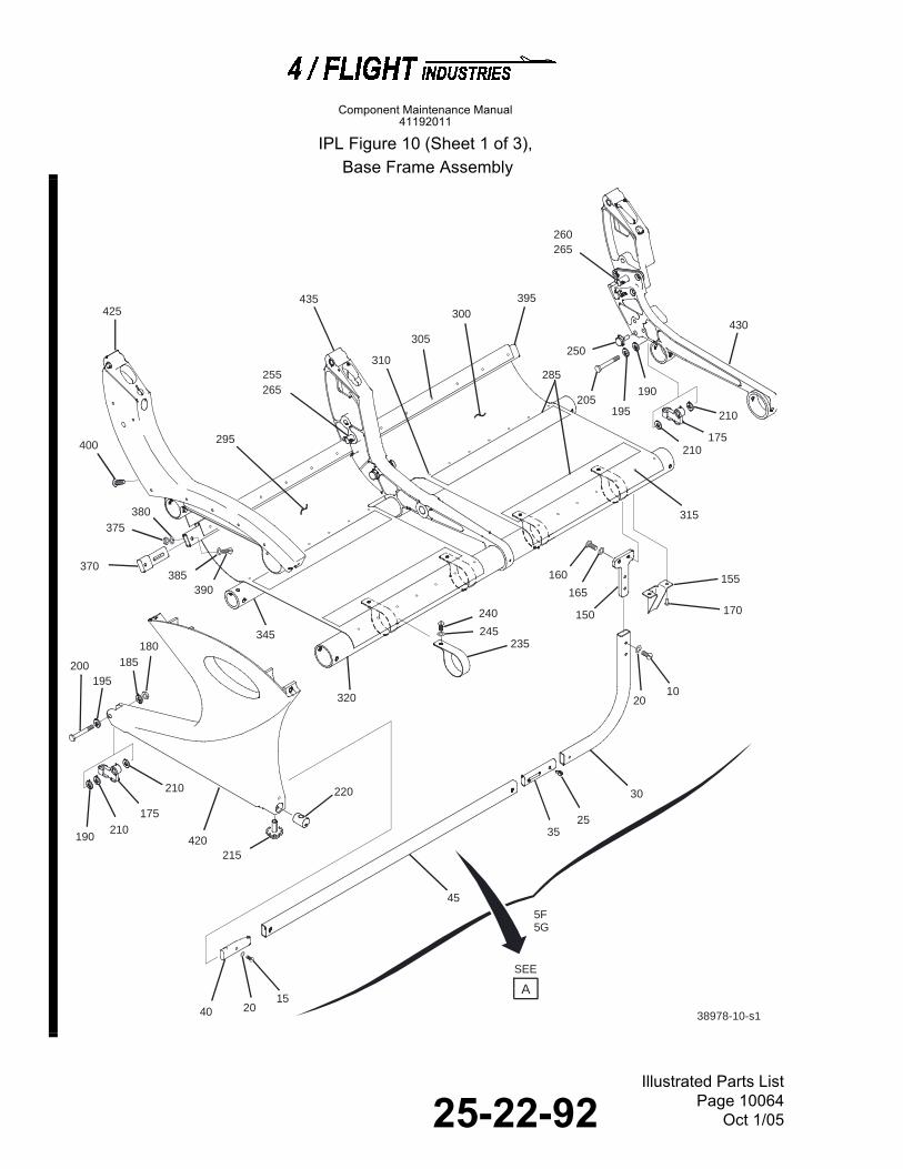
25-22-92Illustrated Parts List
Page 10064Oct 1/05
Component Maintenance Manual41192011
IPL Figure 10 (Sheet 1 of 3),
Base Frame Assembly
420
2010
155
150
160
165
170
30
2015
210
175
200 185180
215
220
240
245235
260265
250
390385
380375
370
395
400
300435
285
430425
195
190
210
210
175
205190
210
305
310
315
345
320
295
38978-10-s1
195
2535
40
45
255
265
A
SEE
5F5G

25-22-92Illustrated Parts List
Page 10065Oct 1/05
Component Maintenance Manual41192011
IPL Figure 10 (Sheet 2 of 3),
Base Frame Assembly
345(REF)
320(REF)
435(REF)
215
225230
365
355345(REF)
355
320(REF)
325
330
330340
430(REF)
360
355
355
350
325330
330335420
(REF)
350
425(REF)
38978-10-s2
270
275
280

25-22-92Illustrated Parts List
Page 10066Oct 1/05
Component Maintenance Manual41192011
IPL Figure 10 (Sheet 3 of 3),
Base Frame Assembly
38978-10-s3
110
99
115
120125
130
135
140
140145
80
90
90
95
98
6570
75
5055
60
105
320(REF)
345(REF)
420(REF)
340
330
330
325350
355
360
A
5D5E
80
90
90
95

25-22-92Illustrated Parts List
Page 10067Oct 1/05
Component Maintenance Manual41192011
Airline Eff
Fig& Item Part Number Part Number 1234567Nomenclature Code UPA10 - 1 41191205-501 FRAME ASSY, BASE, STD
(SUPSD BY ITEM 1H)(RF IPL FIG. 7 FOR NHA)
A RF
- 1A 41191205-502 FRAME ASSY, BASE, STD(SUPSD BY ITEM 1J)(RF IPL FIG. 7 FOR NHA)
B RF
- 1B 41191205-503 FRAME ASSY, BASE, LAST(SUPSD BY ITEM 1F)(RF IPL FIG. 7 FOR NHA)
C RF
- 1C 41191205-504 FRAME ASSY, BASE, LAST(SUPSD BY ITEM 1G)(RF IPL FIG. 7 FOR NHA)
D RF
- 1D 41191205-505 FRAME ASSY, BASE, EXIT(SUPSD BY ITEM 1K)(RF IPL FIG. 7 FOR NHA)
E RF
- 1E 41191205-506 FRAME ASSY, BASE, EXIT(SUPSD BY ITEM 1L)(RF IPL FIG. 7 FOR NHA)
F RF
- 1F 41191205-507 FRAME ASSY, BASE, LAST ROW(SUPSDS ITEM 1B)(RF IPL FIG. 7 FOR NHA)
G RF
- 1G 41191205-508 FRAME ASSY, BASE, LAST ROW(SUPSDS ITEM 1C)(RF IPL FIG. 7 FOR NHA)
H RF
- 1H 41191205-513 FRAME ASSY, BASE, STD(SUPSDS ITEM 1)(RF IPL FIG. 7 FOR NHA)
J RF
- 1J 41191205-514 FRAME ASSY, BASE, STD(SUPSDS ITEM 1A)(RF IPL FIG. 7 FOR NHA)
K RF
- 1K 41191205-515 FRAME ASSY, BASE, EXIT, ROW (STEEL)(SUPSDS ITEM 1D)(RF IPL FIG. 7 FOR NHA)
L RF
- 1L 41191205-516 FRAME ASSY, BASE, EXIT, ROW (STEEL)(SUPSDS ITEM 1E)(RF IPL FIG. 7 FOR NHA)
M RF
- 5 41191018-502 .BAR ASSY, BAGGAGE(SUPSD BY ITEMS -5D AND -5F)
AEGL 1
- 5A 41191018-501 .BAR ASSY, BAGGAGE(SUPSD BY ITEMS -5E AND -5G)
BFHM
1
5B 41191246-501 .BAR ASSY, BAGGAGE(SUPSD BY ITEM -5F)
CJ 1
- 5C 41191246-502 .BAR ASSY, BAGGAGE(SUPSD BY ITEM -5G)
DK 1
5D 41191246-503 .BAR ASSY, BAGGAGE, SWING-OUT G 15E 41191246-504 .BAR ASSY, BAGGAGE, SWING-OUT H 15F 41191018-502 .BAR ASSY, BAGGAGE JL 15G 41191018-501 .BAR ASSY, BAGGAGE
ATTACHING PARTSKM 1
10 NAS603-6 .SCREW ABEFJ-M
2
15 NAS603-12 .SCREW ABEFJ-M
1

25-22-92Illustrated Parts List
Page 10068Oct 1/05
Component Maintenance Manual41192011
10 20 AN960-10L .WASHER (ALT) ABEF
J-M3
- 20A NAS1149F0332P .WASHER ---*---
ABEFJ-M
3
25 MS171587 ..PIN, SPRING ABEFJ-M
2
30 41191018-1 ..TUBE AEJ-M
1
- 30A 41191018-2 ..TUBE BFJ-M
1
35 41031072-1 ..PLUG ABEFJ-M
1
40 41191127-501 ..PLUG ASSY ABEFJ-M
1
45 41191018-3 ..TUBE ABEFJ-M
1
50 41191244-3 ..KNOBATTACHING PARTS
CDGH
1
55 NAS514P1032-12 ..SCREW---*---
CDGH
1
60 41191244-501 ..LATCH ASSY CDGH
1
65 MS171587 ..PIN, SPRING CDGH
2
70 41191127-3 ..PLUG CDGH
2
75 41191242-501 ..BAR ASSY, BAGGAGE(SUPSD BY ITEM -75B)
CJ 1
- 75A 41191242-502 ..BAR ASSY, BAGGAGE(SUPSD BY ITEM -75C)
DK 1
- 75B 41191242-503 ..BAR ASSY, BAGGAGE(SUPSDS ITEM 75)
G 1
- 75A 41191242-504 ..BAR ASSY, BAGGAGEATTACHING PARTS
DH 1
80 MS21042L4 ..NUT CDGH
2
85 5610-560-031 DELETED90 AN960-416L ..WASHER
(SUPSD BY ITEM -90A)CDJK
4
- 90A NAS1149F0432P ..WASHER(SUPSDS ITEM 90)
CDGH
4
95 NAS6204-21 ..BOLT(SUPSD BY ITEM 95)
JK 1
- 95A NAS6204-22 ..BOLT(SUPSDS ITEM 95)---*---
GH 2
- 96 41191244-7 ..DOUBLERATTACHING PARTS
GH 1
- 97 MS171587 ..PIN, SPRING---*---
GH 2
98 41191243-501 ..A-FRAME ASSY, BAGGAGE BAR GH 199 41031071-1 ..CAP GH 1
100 41191243-501 DELETED
Airline EffFig& Item Part Number Part Number 1234567Nomenclature Code UPA

25-22-92Illustrated Parts List
Page 10069Oct 1/05
Component Maintenance Manual41192011
10 105 41191245-501 .LATCH ASSY, SPRING CG 1
- 105A 41191245-502 .LATCH ASSY, SPRING DH 1110 41191245-3 ..CAP, END
ATTACHING PARTSCDGH
1
115 NAS514P832-6 ..SCREW(SUPSD BY ITEM -115A)
CDJK
1
- 115A NAS514P832-7 ..SCREW(SUPSDS ITEM 115)
GH 1
120 K27 ..SPRING (V56988) CDGH
1
125 41191245-503 ..PIN ASSY, LATCH GDGH
1
130 41191244-5 ..GUIDE CG 1- 130A 41191244-6 ..GUIDE
ATTACHING PARTSDH 1
135 MS21042-08 ..NUT CDGH
2
140 AN960-8 ..WASHER CDGH
4
145 NAS602-8 ..SCREW(SUPSD BY ITEM -145A)
CDJK
2
- 145A NAS602-10 ..SCREW(SUPSDS ITEM 145)---*---
GH 2
150 41031025-501 .BRACKET ASSY ABEFJ-M
1
155 41031033-1 .BRACKETATTACHING PARTS
ABEFJ-M
1
160 NAS603-10 .SCREW ABEFJ-M
2
165 AN960-10L .WASHER (ALT) ABEFJ-M
2
- 165A NAS1149F0332P .WASHER ABEFJ-M
2
170 SD54BS .RIVET (V45722)---*---
ABEFJ-M
2
175 47886-13 .FITTING, REAR TRACK (V31272)ATTACHING PARTS
2
180 F52NKTE054 .NUT, CAP (V98474) 1185 AN960-516 .WASHER (ALT) 1
- 185A NAS1149F0563P .WASHER 1190 5613-80-031 .WASHER (V86298) 2195 AN960-516L .WASHER (ALT) 2
- 195A NAS1149F0532P .WASHER 2200 NAS623-5-20 .BOLT 1205 NAS6205-25 .BOLT
---*---1
210 41031135-1 .GROMMET 4215 41031038-501 .STUD ASSY, FRONT 2220 41031104-501 .TRUNNION 1225 41041031-501 .TRUNNION 1
Airline EffFig& Item Part Number Part Number 1234567Nomenclature Code UPA

25-22-92Illustrated Parts List
Page 10070Oct 1/05
Component Maintenance Manual41192011
10 230 41191028-1 .ADAPTER, FWD OUTBOARD ACE
GJL1
- 230A 41191028-2 .ADAPTER, FWD OUTBOARD BDFHKM
1
235 41031133-501 .STRAP ASSYATTACHING PARTS
4
240 NAS603-7 .SCREW 4245 AN960-10L .WASHER (ALT) 4
- 245A NAS1149F0332P .WASHER ---*---
4
250 41031105-1 .STUD, SEAT BELT 4255 41191031-501 .STOP ASSY, FOODTRAY 3260 41191031-505 .STOP ASSY, FOODTRAY
ATTACHING PARTS1
265 41031026-1 .SCREW---*---
4
270 BS18303-3A .STUD, DIRECTIONAL (V3DCM5)ATTACHING PARTS
4
275 1693-0414 .RIVET (V0EV66) 4280 NAS620-5L .WASHER
---*---4
285 4FSP0002-59 .VELCRO, LOOP, 2 INCH, FOSSIL AR- 290 4FSP0002-57 .VELCRO, LOOP, 1 INCH, FOSSIL AR
295 41191032-5 .DIAPHRAGM ACE GJL
1
- 295A 41191032-6 .DIAPHRAGM BDF HKM
1
300 41191032-7 .DIAPHRAGM ACE GJL
1
- 300A 41191032-8 .DIAPHRAGMATTACHING PARTS
BDF HKM
1
305 SD53BS .RIVET (V45722) 13310 SD54BS .RIVET (V45722) 2315 SD52BS .RIVET (V45722)
---*---19
320 41191030-519 .TUBE ASSY, FRONT(SUPSD BY ITEM -320D)
AEGL 1
- 320A 41191030-520 .TUBE ASSY, FRONT(SUPSD BY ITEM -320E)
BFHM
1
- 320B 41191030-515 .TUBE ASSY, FRONT(SUPSD BY ITEM -320F)
CJ 1
- 320C 41191030-516 .TUBE ASSY, FRONT(SUPSD BY ITEM -320G)
DK 1
- 320D 41191030-523 .TUBE ASSY, FRONT(SUPSDS ITEM 320)
G 1
- 320E 41191030-524 .TUBE ASSY, FRONT(SUPSDS ITEM -320A)
H 1
- 320F 41191030-519 .TUBE ASSY, FRONT(SUPSDS ITEM -320B)
JL 1
- 320G 41191030-520 .TUBE ASSY, FRONT(SUPSDS ITEM -320C)ATTACHING PARTS
KM 1
Airline EffFig& Item Part Number Part Number 1234567Nomenclature Code UPA

25-22-92Illustrated Parts List
Page 10071Oct 1/05
Component Maintenance Manual41192011
10 325 MS21042L4 .NUT ABEF
GH3
- 325A MS21042L4 .NUT CDJ-M
2
330 AN960-416L .WASHER (ALT) 4- 330A NAS1149F0432P .WASHER 4- 332 NAS1149F0463P .WASHER CD
GH2
- 332A AN960-416 .WASHER (ALT) CDGH
2
335 NAS6204-42 .BOLT 1340 NAS6204-36 .BOLT ABEF
GH2
- 340A NAS6204-36 .BOLT---*---
CDJ-M
1
345 41191030-503 .TUBE ASSY, REAR(SUPSD BY ITEM -345F)
AG 1
- 345A 41191030-504 .TUBE ASSY, REAR(SUPSD BY ITEM -345G)
BH 1
- 345B 41191030-517 .TUBE ASSY, REAR(SUPSD BY ITEM -345H)
CJ 1
- 345C 41191030-518 .TUBE ASSY, REAR(SUPSD BY ITEM -345J)
DK 1
- 345D 41191030-509 .TUBE ASSY, REAR(SUPSD BY ITEM -345K)
EL 1
- 345E 41191030-510 .TUBE ASSY, REAR(SUPSD BY ITEM -345L)
FM 1
345F 41191030-525 .TUBE ASSY, REAR(SUPSDS ITEM 345)
G 1
- 345G 41191030-526 .TUBE ASSY, REAR(SUPSDS ITEM -345A)
H 1
- 345H 41191030-503 .TUBE ASSY, REAR(SUPSDS ITEM -345B)
J 1
- 345J 41191030-504 .TUBE ASSY, REAR(SUPSDS ITEM -345C)
K 1
- 345K 41191030-509 .TUBE ASSY, REAR (STEEL)(SUPSDS ITEM -345D)
L 1
- 345L 41191030-510 .TUBE ASSY, REAR (STEEL)(SUPSDS ITEM-345D)ATTACHING PARTS
M 1
350 MS21042L4 .NUT 3355 AN960-416L .WASHER (ALT) AB
G-K6
- 355A NAS1149F0432P .WASHER ABG-K
6
- 355B AN960-416L .WASHER CD 8- 355C NAS1149F0432P .WASHER (ALT) CD 8- 355D AN960-416L .WASHER EF 4- 355E NAS1149F0432P .WASHER (ALT) EF 4- 355F NAS1149F0463P .WASHER EFLM 2- 355G AN960-416 .WASHER (ALT) EFLM 2
Airline EffFig& Item Part Number Part Number 1234567Nomenclature Code UPA
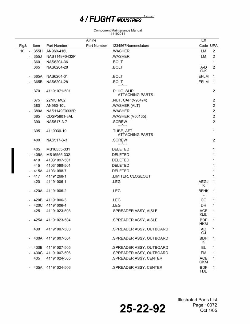
25-22-92Illustrated Parts List
Page 10072Oct 1/05
Component Maintenance Manual41192011
10 - 355H AN960-416L .WASHER LM 2
- 355J NAS1149F0432P .WASHER LM 2360 NAS6204-36 .BOLT 1365 NAS6204-28 .BOLT A-D
G-K2
- 365A NAS6204-31 .BOLT EFLM 1- 365B NAS6204-28 .BOLT
---*---EFLM 1
370 41191071-501 .PLUG, SLIPATTACHING PARTS
2
375 22NKTM02 .NUT, CAP (V98474) 2380 AN960-10L .WASHER (ALT) 2
- 380A NAS1149F0332P .WASHER 2385 CDSP5801-3AL .WASHER (V56135) 2390 NAS517-3-7 .SCREW
---*---2
395 4119030-19 .TUBE, AFTATTACHING PARTS
1
400 NAS517-3-3 .SCREW---*---
2
405 MS16555-331 DELETED 1- 405A MS16555-332 DELETED 1
410 41031097-501 DELETED 1415 41031098-501 DELETED 1
- 415A 41031098-7 DELETED 1- 417 41191268-1 .LIMITER, CLOSEOUT 1
420 41191006-1 .LEG AEGJK
1
- 420A 41191006-2 .LEG BFHKL
1
- 420B 41191006-3 .LEG CG 1- 420C 41191006-4 .LEG DH 1
425 41191023-503 .SPREADER ASSY, AISLE ACEGJL
1
- 425A 41191023-504 .SPREADER ASSY, AISLE BDFHKM
1
430 41191007-503 .SPREADER ASSY, OUTBOARD ACGJ
1
- 430A 41191007-504 .SPREADER ASSY, OUTBOARD BDHK
1
- 430B 41191007-505 .SPREADER ASSY, OUTBOARD EL 1- 430C 41191007-506 .SPREADER ASSY, OUTBOARD FM 1
435 41191024-505 .SPREADER ASSY, CENTER ACEGKM
1
- 435A 41191024-506 .SPREADER ASSY, CENTER BDFHJL
1
Airline EffFig& Item Part Number Part Number 1234567Nomenclature Code UPA