Embed Size (px)
Citation preview
25 Years of Passive House in
Darmstadt Kranichstein
Sponsored by the Hessian Ministry of Economics, Energy, Transport, and Regional
Development
Passive House Institute Darmstadt
September 2016
25 Years of Passive House in
Darmstadt Kranichstein
Authors:
Dr. Wolfgang Feist1
Dr. Witta Ebel
Søren Peper
Wolfgang Hasper
Dr. Rainer Pfluger2
Dr. Martin Kirchmair3
Published by:
PASSIVHAUS INSTITUT
Dr. Wolfgang Feist
Rheinstraße 44/46
D‐64283 Darmstadt
Tel: 06151‐82699‐0
E‐Mail: [email protected]
www.passiv.de
Darmstadt, September 2016
This report was funded by the Hessian
Ministry of Economics, Energy, Transport,
and Regional Development.
We would like to thank Prof. Dr. Andreas
Saxer of the University of Innsbruck / Unit
for Material Technology
Picture credits:
All images and graphs in this report, are
owned by the Passive House Institute. If
not, the respective sources are named.
1 Passive House Darmstadt and University of Innsbruck, Unit for Energy‐Efficient Building 2 University of Innsbruck, Unit for Energy‐Efficient Building, Technikerstr. 13, A‐6020 Innsbruck 3 University of Innsbruck, Institute of Microbiology, Technikerstr. 25d, A‐6020 Innsbruck
25 Years of Passive House
Contents
1 Introduction and Summary .................................................................................................... 4
2 Airtightness ............................................................................................................................ 7
2.1 Airtightness of the roof and connection roof‐wall ............................................................... 10
2.2 Airtightness of walls and of the connection between wall and window frame .................. 14
2.2.1 Connection of floor and window ................................................................................................... 18
2.2.2 Airtightness of switches and electrical outlets in exterior walls ................................................... 20
2.3 Airtightness of the base plate on the ground floor and the connection to
the exterior wall ................................................................................................................... 21
2.4 Replacing window and door seals ........................................................................................ 22
2.5 Long‐term test of airtightness – Measuring results ............................................................. 23
2.6 Conclusions on airtightness ................................................................................................. 26
3 Summary and conclusions .................................................................................................... 27
3.1 Main findings ........................................................................................................................ 27
4 References ............................................................................................................................ 34
5 Appendix .............................................................................................................................. 38
5.1 BlowerDoor measurement protocols .................................................................................. 38
5.1.1 Test report and measuring curve of the BlowerDoor measurement in House A after having
replaced the window and door seals. ........................................................................................... 38
5.1.2 Test report and measuring curve of the BlowerDoor measurement in House B after having
replaced the window and door seals. ........................................................................................... 40
25 Years of Passive House 4
1 Introduction and Summary
The year 2016 marks the 25th anniversary of four builder‐owners in the Darmstadt‐
Kranichstein neighborhood moving into the very first passive house ever. A residential
building with almost no heating? From the point of view of non‐scientists, this involved
many risks. Many ambitious projects following the oil crises had not reached their targets or
the requirements for user behavior were too specific and unrealistic.
Low‐energy houses already had a longer tradition in some Scandinavian countries proving
that passive principles, if carried out correctly, succeed and result in a longer life time than
active systems [Feist 1988a]. Hesse came forward with a small funding program for low‐
energy houses, however, basically none of the builders or architects in Germany wanted to
believe in this. The building industry clearly had not yet been prepared for the necessary
quality of construction. (The Thermal Insulation Regulation from 1982 was still in force.) The
prevailing opinion was that “these few houses in Germany, if their energy consumption was
really as low, were probably inhabited by freezing energy vegetarians”. The plan was to carry
the principle of low‐energy houses to the point where the energy consumption of several
very average families could be reduced to “almost zero”. However, before the first
construction of passive houses, the scientists were not at all convinced that their idea could
turn into a widely applicable standard. The Hessian Ministry of Economics, respectively the
Hessian Ministry for the Environment supported the pioneers with a research project and
funding for the additional cost of construction for the first passive house including an
extensive measuring and evaluation program, which confirmed the predictions and
documented high user satisfaction. This is how the building became a model and prototype
for the new standard. In 1996, the “Working group for cost‐efficient passive houses” was
founded to discuss and spread further developments.
The first passive house in Kranichstein, above all, documented that buildings with a high
level of comfort and very low energy consumption are, in fact, possible – not only in theory,
but in real life, with normal occupants and without performance gap. Today, in 2016, this
may not be a matter of course when it comes to energy‐efficient building, but has been
repeated thousands of times for passive houses in Hesse, Germany, Europe, and all over the
world.
There obviously remained questions that could only be answered in the long run. Part of a
sustainable solution is also that the results can be repeated at any time, particularly
regarding the parameters of comfort and energy consumption. Sustainability also means
that the solutions and materials implemented are durable, that is have a long useful life. The
25 Years of Passive House 5
oldest existing passive house is predestined for such an analysis. Sponsored by the Hessian
Ministry of Economics, the relevant questions have now been analyzed. In the following, a
short overview of the results:
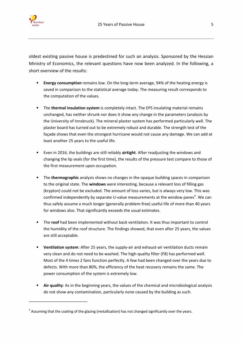
• Energy consumption remains low. On the long‐term average, 94% of the heating energy is
saved in comparison to the statistical average today. The measuring result corresponds to
the computation of the values.
• The thermal insulation system is completely intact. The EPS insulating material remains
unchanged, has neither shrunk nor does it show any change in the parameters (analysis by
the University of Innsbruck). The mineral plaster system has performed particularly well. The
plaster board has turned out to be extremely robust and durable. The strength test of the
façade shows that even the strongest hurricane would not cause any damage. We can add at
least another 25 years to the useful life.
• Even in 2016, the buildings are still reliably airtight. After readjusting the windows and
changing the lip seals (for the first time), the results of the pressure test compare to those of
the first measurement upon occupation.
• The thermographic analysis shows no changes in the opaque building spaces in comparison
to the original state. The windows were interesting, because a relevant loss of filling gas
(krypton) could not be excluded. The amount of loss varies, but is always very low. This was
confirmed independently by separate U‐value measurements at the window panes4. We can
thus safely assume a much longer (generally problem‐free) useful life of more than 40 years
for windows also. That significantly exceeds the usual estimates.
• The roof had been implemented without back ventilation. It was thus important to control
the humidity of the roof structure. The findings showed, that even after 25 years, the values
are still acceptable.
• Ventilation system: After 25 years, the supply‐air and exhaust‐air ventilation ducts remain
very clean and do not need to be washed. The high‐quality filter (F8) has performed well.
Most of the 4 times 2 fans function perfectly. A few had been changed over the years due to
defects. With more than 80%, the efficiency of the heat recovery remains the same. The
power consumption of the system is extremely low.
• Air quality: As in the beginning years, the values of the chemical and microbiological analysis
do not show any contamination, particularly none caused by the building as such.
4 Assuming that the coating of the glazing (metallization) has not changed significantly over the years.
25 Years of Passive House 6
Figure 1: Measured annual consumption of heating energy for the period between 1991 and 1996 of all
four units of the first passive house on average. This is compared to a low‐energy house or a
new 2016 building. The savings realized in comparison to the standard for new buildings
(effective for construction) at the time are approximately 94%.
The results from these analyses in combination with the cumulative experience from the
project lead to the following conclusions:
Passive houses do work and are durable. Their energy efficiency can be planned and without
any performance gap. The design agrees with the user requirements. Thermal comfort and
consistently high air quality are guaranteed. Passive houses do neither require any special
knowledge or operation nor any complicated regulation or expensive energy consumption.
The additional investment for passive houses is low and is amortized by the energy savings
alone.
The passive‐house design has proven to be successful. Passive houses allow for a cost‐
effective and user‐friendly implementation of the nearly‐ zero energy buildings of the
European Energy Performance of Buildings Directive. All builders, builder‐owners, and
planners are well advised to refer to this standard and to implement it consistently.
25 Years of Passive House 7
2 Airtightness
For an energy‐efficient building, for example with passive‐house standard, a good airtight
building envelope is necessary. There are many reasons why: protecting the structure,
preventing drafts, comfort, perfect functioning of the ventilation system, as well as
improving sound insulation. Based on accumulated experience with airtight buildings, [Feist
1993] determined a target value of below 0.6 h‐1 for the 50 Pa pressure‐test air change as
effective. Here is the context for this target:
• Until construction of the prototype in Kranichstein, the characteristic values in pressure
tests of low‐energy houses in Germany were between 1 and 4 h‐1 with an accumulation
around 3 h‐1. Only very few buildings came close to 1 h‐1. The building sector in Germany
had had little experience with the construction of good airtight building envelopes.
• In Sweden, however, pressure tests of new buildings for a few years had already been
regularly recording air changes of around 1 h‐1, even with most of the building envelopes
constructed completely out of timber studs, which were generally considered
complicated regarding airtightness. Some Swedish pressure tests already showed values
as low as approximately 0.5 h‐1. This proved that with Swedish building practice such low
residual leakages could be achieved.
• If you calculate with a permanent flow ratio of e = 0.04 in the infiltration formula, at a
target n50 value of 0.6 h‐1, this results in a median annual infiltration of 0.024 h‐1. In a
typical cold and temperate climate, this means heat losses from infiltration of around
320 kWh/a for the entire building or based on the living area of around 2kWh/(m²a).
Considering a limit of 10 kWh/(m²a) for the energy parameter of heat energy, this is
already a significant contribution.
The last point shows that for a passive house, a significantly higher residual leakage could
not have been tolerated without endangering the overall objectives. However, the first point
shows that airtightness according to the passive‐house objective already meant tough
requirements when compared to common building practice in Germany at the time. The first
passive house had to go beyond excellent low‐energy buildings and achieve much better
airtightness.
The energetic impact of the airtightness of the end‐of‐terrace house on the heating demand
calculated as well as the heating requirement can easily be determined with a parameter
variation (Figure 108). It is remarkable how strong the impact of building airtightness is, if all
other building components remain the same. Today's legal requirements according to the
25 Years of Passive House 8
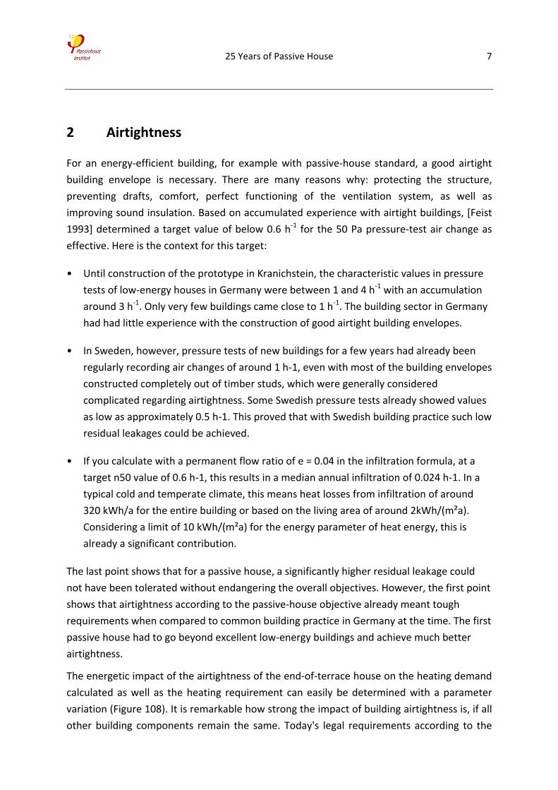
German Energy Savings Regulation (EnEV) are at n50 = 1.5 h‐1 for buildings with a ventilation
system and n50 = 3.0 h‐1 for buildings without a ventilation system. The graph below shows
how difficult it is to achieve passive‐house standard with such bad airtightness parameters.
Figure 2: Variation of airtightness and impact on heating demand for the first passive house (end‐of‐row
house) according to the balance calculated with the Passive House Planning Package (PHPP).
The airtightness design of the first passive house – at least from today's point of view ‐
applied “classic” solutions for the surface structures: PE‐foil in a lightweight roof, interior
plaster of the solid walls, and a cast‐in‐place concrete base plate. A tabular overview of the
connections can be seen in Table 6. It must be considered that many of today's products
were not yet available in 1991. However, the following detailed illustrations as well as the
airtightness tests conducted (BlowerDoor measurement) show that long‐term solutions had
been implemented, particularly of the connections between different surface sealings.
25 Years of Passive House 9
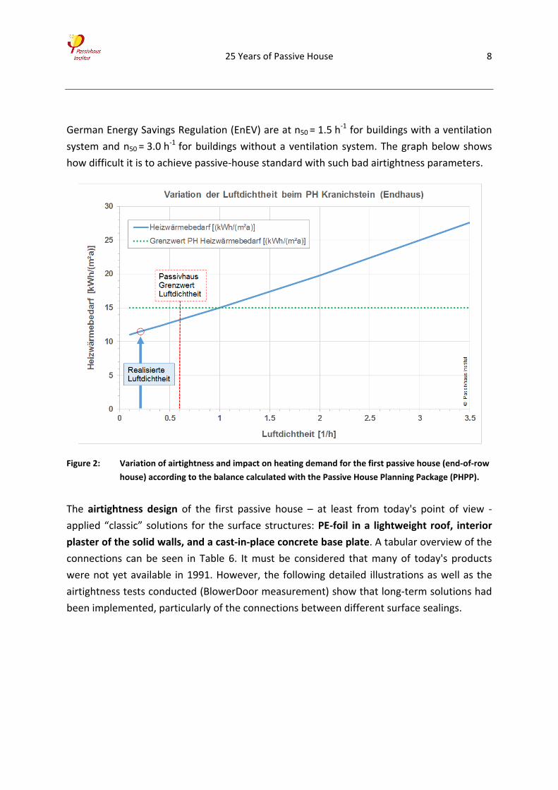
Table 1: Airtight connections in the terraced house in Darmstadt‐Kranichstein (Source: [Feist 1995a])
Connection
of/to
basement
ceiling sash blind frame exterior wall roof
roof
foil plastered
into the gypsum
plaster
foils are glued to
each other (butyl‐
rubber adhesive
tapes)
exterior
wall
gypsum plaster
extended to the
ceiling slab
plaster end rail,
grouted against
the frame with
acrylate sealant
end‐to‐end
gypsum plaster
blind frame
bolted triangle
border grouted
with silicone
lip seal
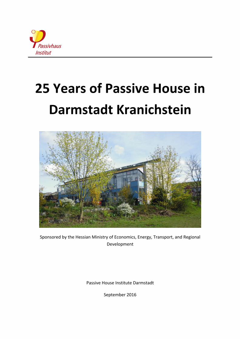
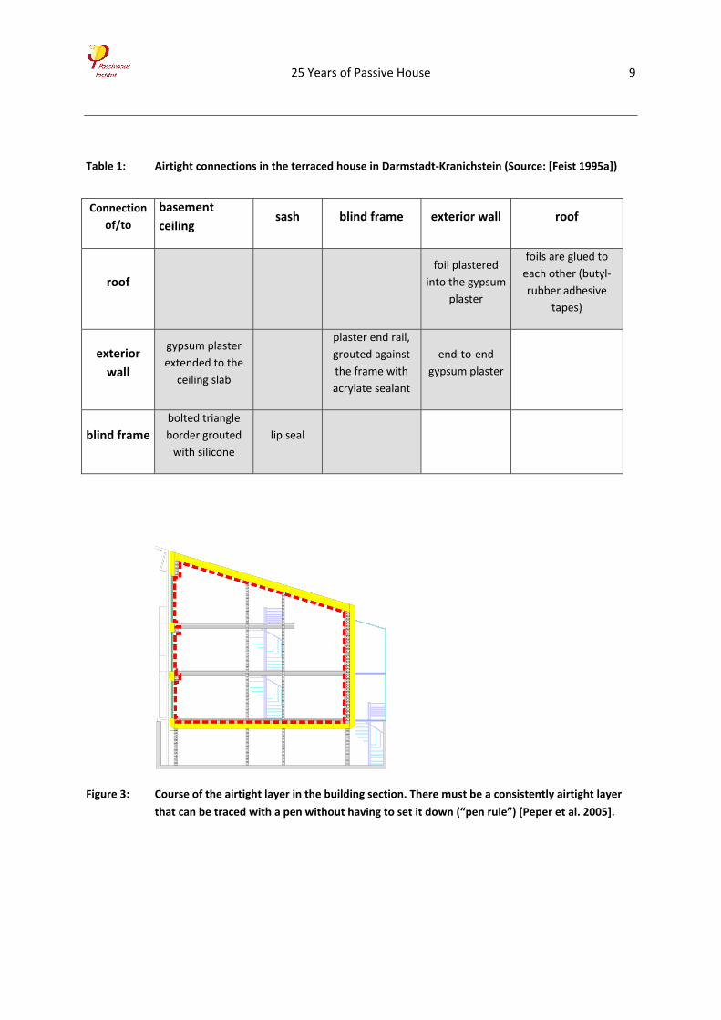
Figure 3: Course of the airtight layer in the building section. There must be a consistently airtight layer
that can be traced with a pen without having to set it down (“pen rule”) [Peper et al. 2005].
25 Years of Passive House 10
2.1 Airtightness of the roof and connection roof‐wall
For the roof, special double‐T lightweight beams were used which allow for
good thermal insulation with very low thermal bridge effects. The airtightness
of this structure is achieved with an end‐to‐end PE‐foil stapled in large panels
onto the counter battens. According to the plans, in each room of the top floor
only one large sheet of foil was to be laid from gable wall to gable wall making
adhesions between pieces of foil unnecessary. Such adhesions can be done durably and
reliably airtight with double‐sided butyl adhesive tape. If the room is not too big, however,
laying only one sheet reduces the amount of work.
Connection roof‐wall: For the roof (light‐weight structure), the PE‐foil constitutes the
airtight layer. For the solidly built wall, it is the continuous gypsum plaster. A completely
airtight connection of these two layers was made possible by plastering the foil: The foil was
laid before doing the interior plastering, which also has the advantage that the moisture
during plastering does not penetrate the lightweight structure. At the edges with the solid
elements, the foil was left to protrude 8 to 20 cm and was laid onto the solid element (shell
part). The solid building component was then fixed with a rib‐mash plaster base (nailed or
braced). These fixings may also go through the foil, but should have a distance of at least
5cm from the edge of the building elements. In the last step, the foil can now be completely
plastered into the interior plaster, which is applied according to standard procedure (Figure
4 and Figure 5). The connection created can be easily implemented and is absolutely airtight.
Later, woodchip wallpaper was applied to ceilings and walls (The finish is, however, of no
relevance for the result.).
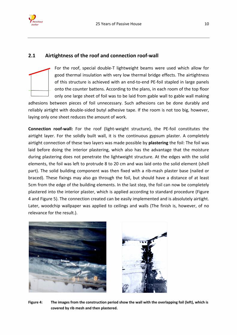
Figure 4: The images from the construction period show the wall with the overlapping foil (left), which is
covered by rib mesh and then plastered.
25 Years of Passive House 11
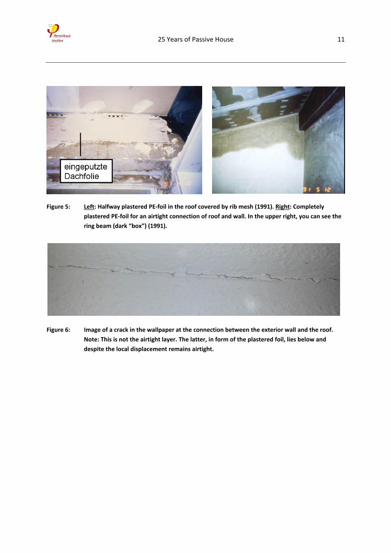
Figure 5: Left: Halfway plastered PE‐foil in the roof covered by rib mesh (1991). Right: Completely
plastered PE‐foil for an airtight connection of roof and wall. In the upper right, you can see the
ring beam (dark “box”) (1991).
Figure 6: Image of a crack in the wallpaper at the connection between the exterior wall and the roof.
Note: This is not the airtight layer. The latter, in form of the plastered foil, lies below and
despite the local displacement remains airtight.
25 Years of Passive House 12
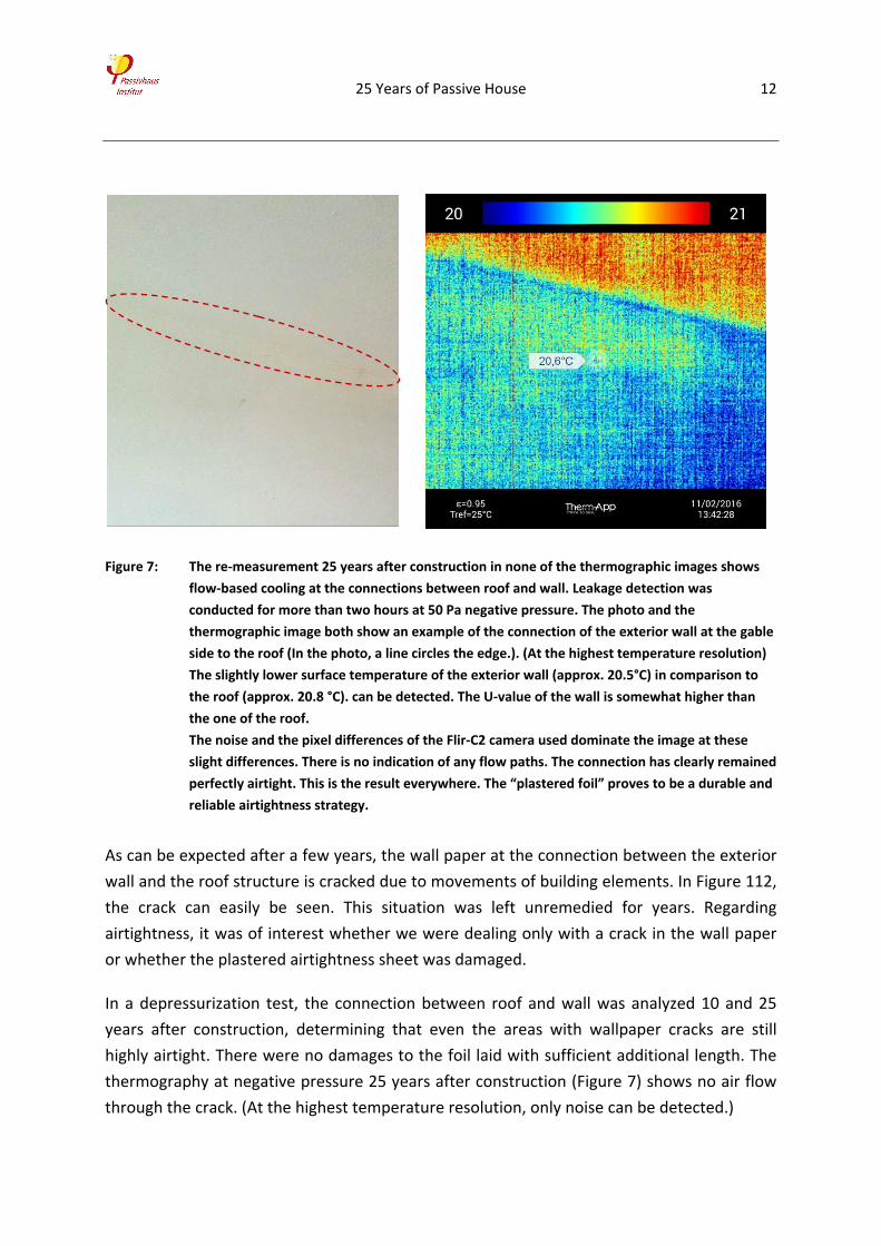
Figure 7: The re‐measurement 25 years after construction in none of the thermographic images shows
flow‐based cooling at the connections between roof and wall. Leakage detection was
conducted for more than two hours at 50 Pa negative pressure. The photo and the
thermographic image both show an example of the connection of the exterior wall at the gable
side to the roof (In the photo, a line circles the edge.). (At the highest temperature resolution)
The slightly lower surface temperature of the exterior wall (approx. 20.5°C) in comparison to
the roof (approx. 20.8 °C). can be detected. The U‐value of the wall is somewhat higher than
the one of the roof.
The noise and the pixel differences of the Flir‐C2 camera used dominate the image at these
slight differences. There is no indication of any flow paths. The connection has clearly remained
perfectly airtight. This is the result everywhere. The “plastered foil” proves to be a durable and
reliable airtightness strategy.
As can be expected after a few years, the wall paper at the connection between the exterior
wall and the roof structure is cracked due to movements of building elements. In Figure 112,
the crack can easily be seen. This situation was left unremedied for years. Regarding
airtightness, it was of interest whether we were dealing only with a crack in the wall paper
or whether the plastered airtightness sheet was damaged.
In a depressurization test, the connection between roof and wall was analyzed 10 and 25
years after construction, determining that even the areas with wallpaper cracks are still
highly airtight. There were no damages to the foil laid with sufficient additional length. The
thermography at negative pressure 25 years after construction (Figure 7) shows no air flow
through the crack. (At the highest temperature resolution, only noise can be detected.)
25 Years of Passive House 13
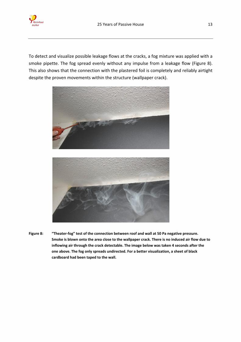
To detect and visualize possible leakage flows at the cracks, a fog mixture was applied with a
smoke pipette. The fog spread evenly without any impulse from a leakage flow (Figure 8).
This also shows that the connection with the plastered foil is completely and reliably airtight
despite the proven movements within the structure (wallpaper crack).
Figure 8: “Theater‐fog” test of the connection between roof and wall at 50 Pa negative pressure.
Smoke is blown onto the area close to the wallpaper crack. There is no induced air flow due to
inflowing air through the crack detectable. The image below was taken 4 seconds after the
one above. The fog only spreads undirected. For a better visualization, a sheet of black
cardboard had been taped to the wall.
25 Years of Passive House 14
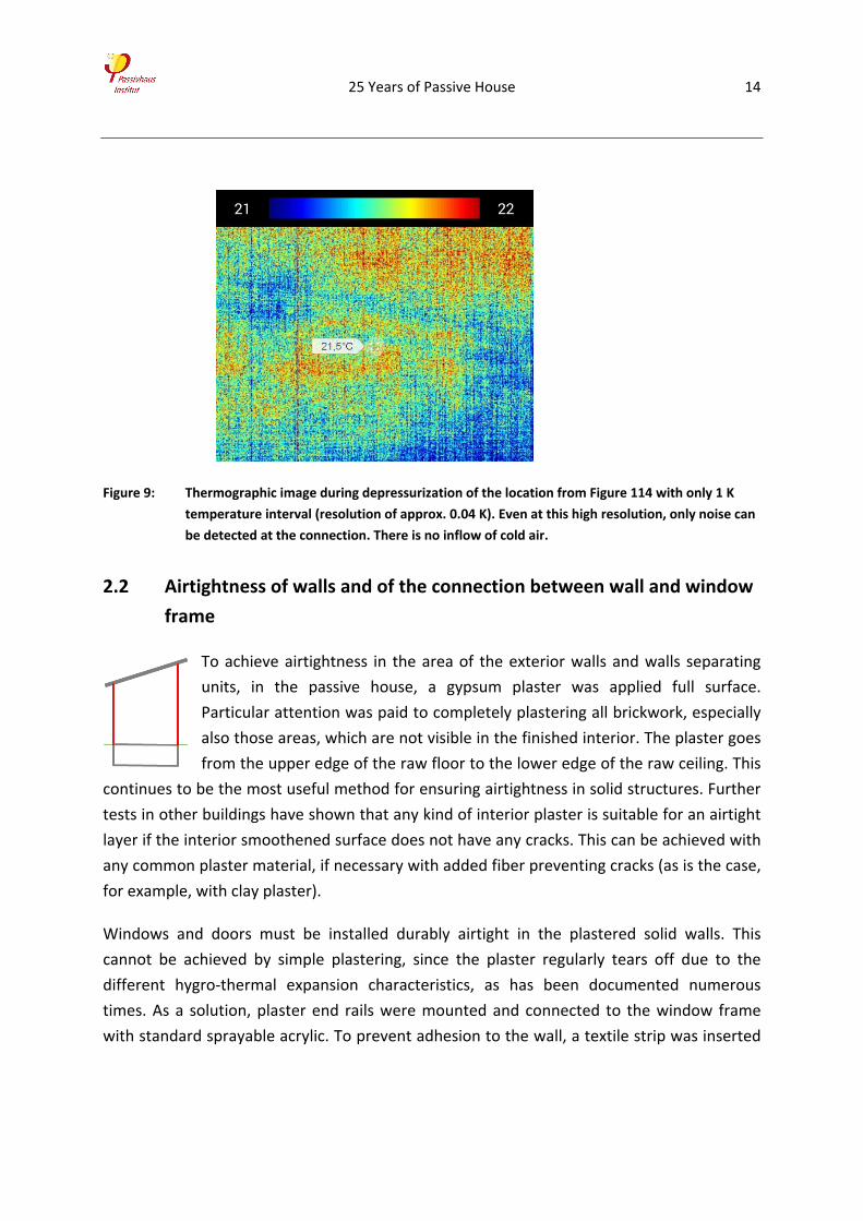
Figure 9: Thermographic image during depressurization of the location from Figure 114 with only 1 K
temperature interval (resolution of approx. 0.04 K). Even at this high resolution, only noise can
be detected at the connection. There is no inflow of cold air.
2.2 Airtightness of walls and of the connection between wall and window
frame
To achieve airtightness in the area of the exterior walls and walls separating
units, in the passive house, a gypsum plaster was applied full surface.
Particular attention was paid to completely plastering all brickwork, especially
also those areas, which are not visible in the finished interior. The plaster goes
from the upper edge of the raw floor to the lower edge of the raw ceiling. This
continues to be the most useful method for ensuring airtightness in solid structures. Further
tests in other buildings have shown that any kind of interior plaster is suitable for an airtight
layer if the interior smoothened surface does not have any cracks. This can be achieved with
any common plaster material, if necessary with added fiber preventing cracks (as is the case,
for example, with clay plaster).
Windows and doors must be installed durably airtight in the plastered solid walls. This
cannot be achieved by simple plastering, since the plaster regularly tears off due to the
different hygro‐thermal expansion characteristics, as has been documented numerous
times. As a solution, plaster end rails were mounted and connected to the window frame
with standard sprayable acrylic. To prevent adhesion to the wall, a textile strip was inserted
25 Years of Passive House 15
beforehand (ensuring “two‐flank adhesion”5 – a round cord serves the same purpose). The
set‐up is explained by the following illustrations and the airtightness of the detail 25 years
after construction is documented by thermographic images.
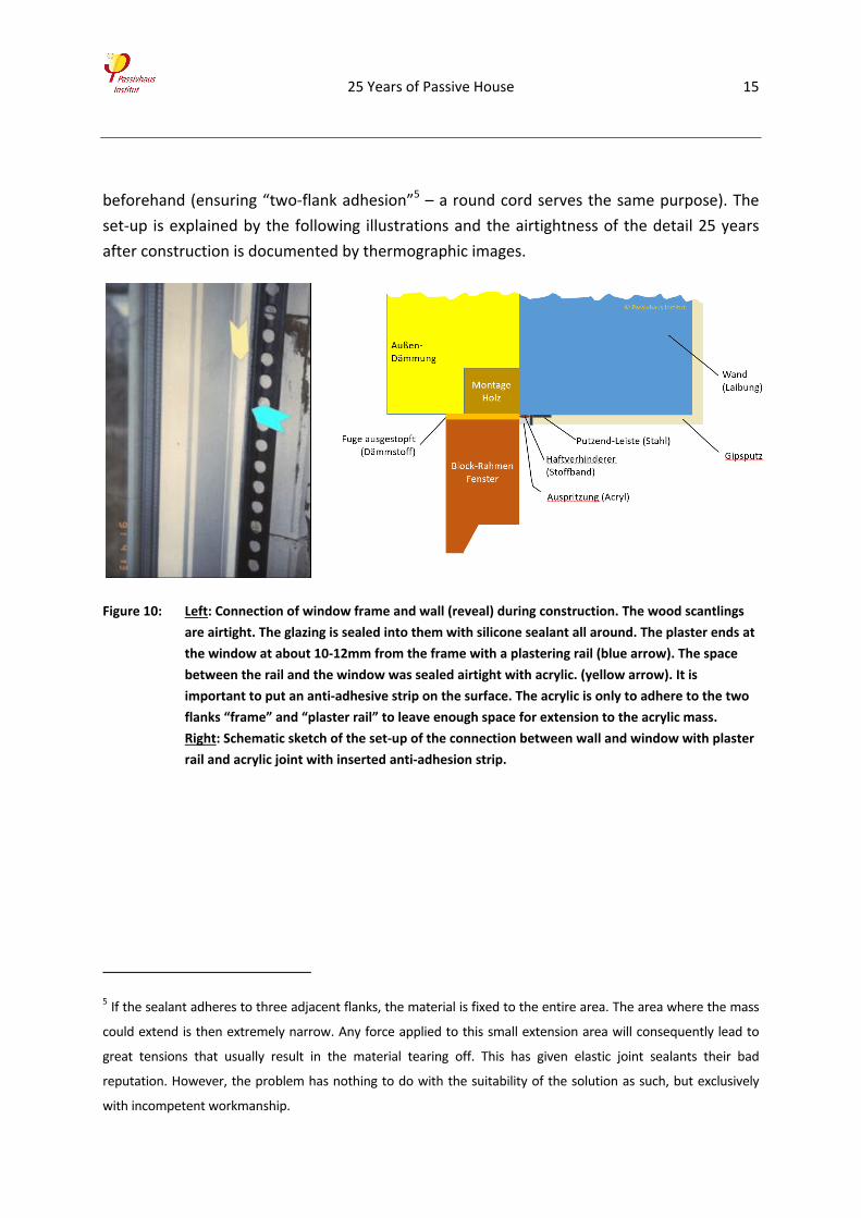
Figure 10: Left: Connection of window frame and wall (reveal) during construction. The wood scantlings
are airtight. The glazing is sealed into them with silicone sealant all around. The plaster ends at
the window at about 10‐12mm from the frame with a plastering rail (blue arrow). The space
between the rail and the window was sealed airtight with acrylic. (yellow arrow). It is
important to put an anti‐adhesive strip on the surface. The acrylic is only to adhere to the two
flanks “frame” and “plaster rail” to leave enough space for extension to the acrylic mass.
Right: Schematic sketch of the set‐up of the connection between wall and window with plaster
rail and acrylic joint with inserted anti‐adhesion strip.
5 If the sealant adheres to three adjacent flanks, the material is fixed to the entire area. The area where the mass
could extend is then extremely narrow. Any force applied to this small extension area will consequently lead to
great tensions that usually result in the material tearing off. This has given elastic joint sealants their bad
reputation. However, the problem has nothing to do with the suitability of the solution as such, but exclusively
with incompetent workmanship.
25 Years of Passive House 16
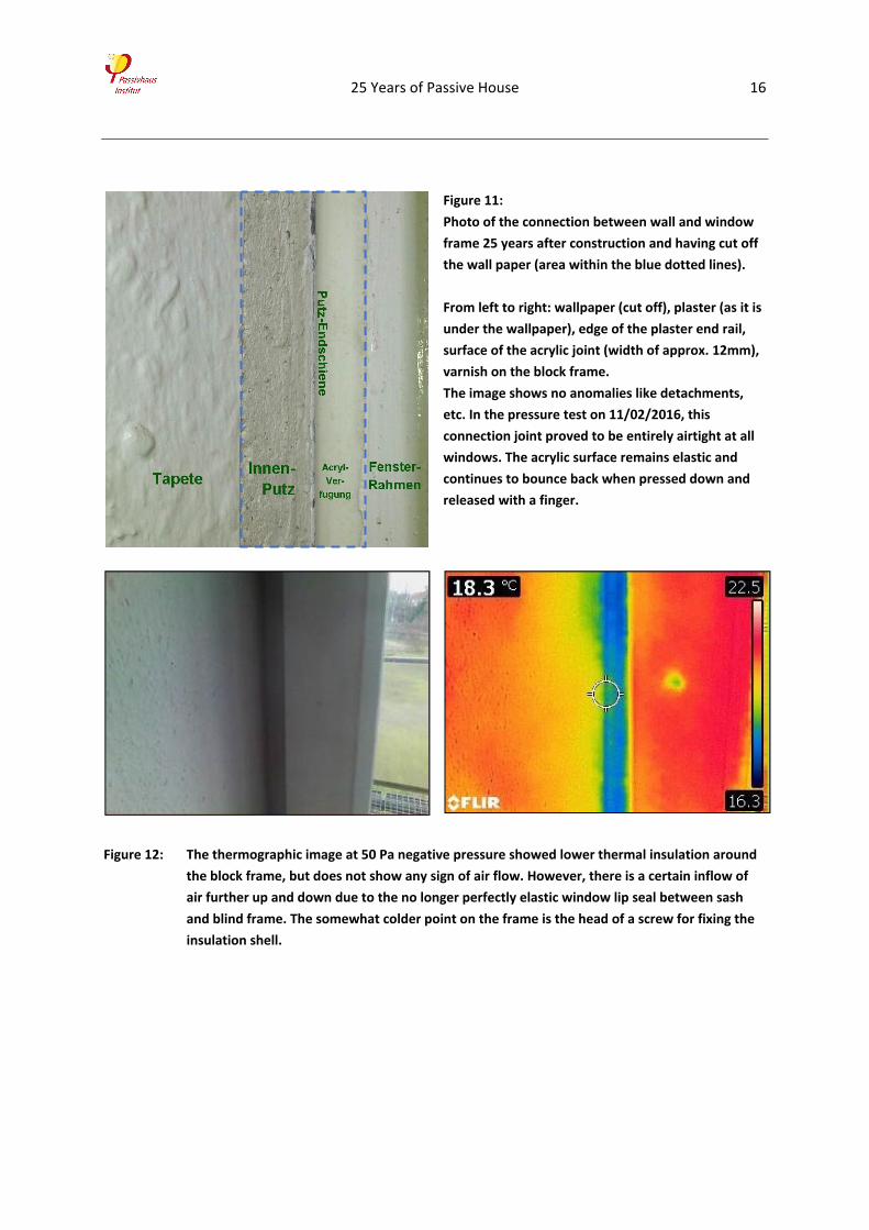
Figure 11:
Photo of the connection between wall and window
frame 25 years after construction and having cut off
the wall paper (area within the blue dotted lines).
From left to right: wallpaper (cut off), plaster (as it is
under the wallpaper), edge of the plaster end rail,
surface of the acrylic joint (width of approx. 12mm),
varnish on the block frame.
The image shows no anomalies like detachments,
etc. In the pressure test on 11/02/2016, this
connection joint proved to be entirely airtight at all
windows. The acrylic surface remains elastic and
continues to bounce back when pressed down and
released with a finger.
Figure 12: The thermographic image at 50 Pa negative pressure showed lower thermal insulation around
the block frame, but does not show any sign of air flow. However, there is a certain inflow of
air further up and down due to the no longer perfectly elastic window lip seal between sash
and blind frame. The somewhat colder point on the frame is the head of a screw for fixing the
insulation shell.
25 Years of Passive House 17
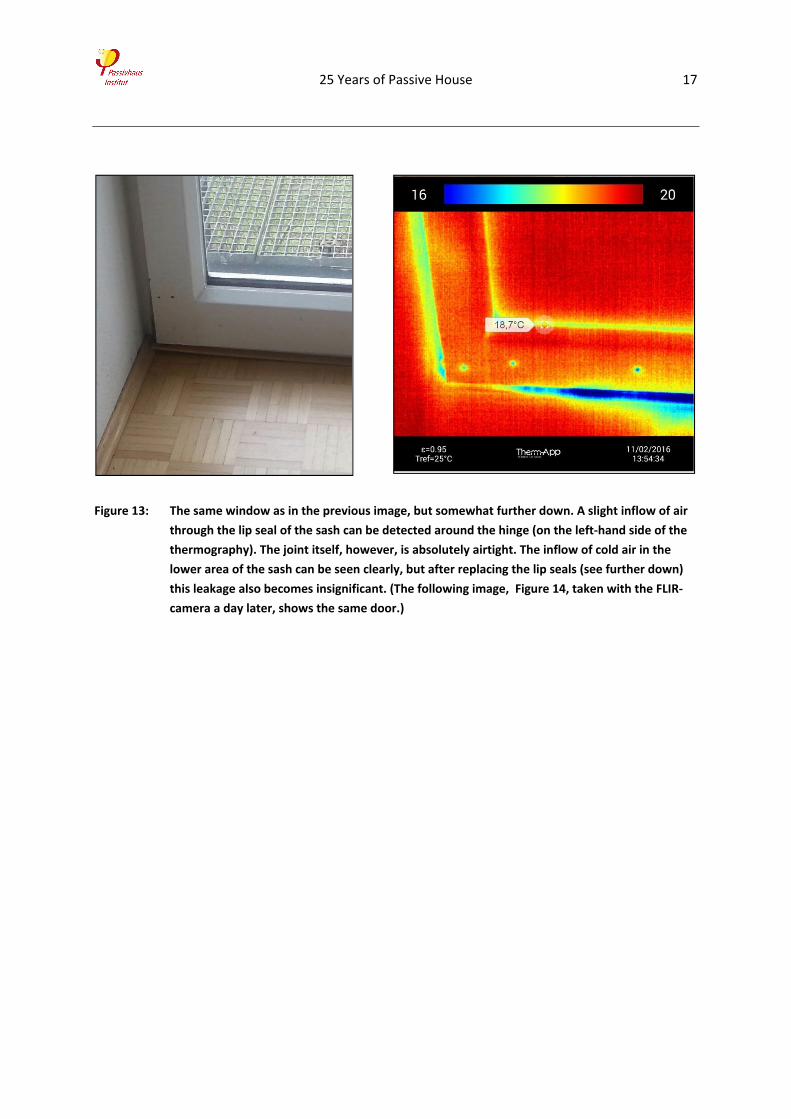
Figure 13: The same window as in the previous image, but somewhat further down. A slight inflow of air
through the lip seal of the sash can be detected around the hinge (on the left‐hand side of the
thermography). The joint itself, however, is absolutely airtight. The inflow of cold air in the
lower area of the sash can be seen clearly, but after replacing the lip seals (see further down)
this leakage also becomes insignificant. (The following image, Figure 14, taken with the FLIR‐
camera a day later, shows the same door.)
25 Years of Passive House 18
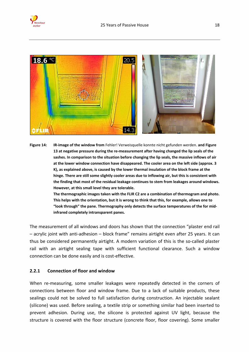
Figure 14: IR‐image of the window from Fehler! Verweisquelle konnte nicht gefunden werden. and Figure
13 at negative pressure during the re‐measurement after having changed the lip seals of the
sashes. In comparison to the situation before changing the lip seals, the massive inflows of air
at the lower window connection have disappeared. The cooler area on the left side (approx. 3
K), as explained above, is caused by the lower thermal insulation of the block frame at the
hinge. There are still some slightly cooler areas due to inflowing air, but this is consistent with
the finding that most of the residual leakage continues to stem from leakages around windows.
However, at this small level they are tolerable.
The thermographic images taken with the FLIR C2 are a combination of thermogram and photo.
This helps with the orientation, but it is wrong to think that this, for example, allows one to
“look through” the pane. Thermography only detects the surface temperatures of the for mid‐
infrared completely intransparent panes.
The measurement of all windows and doors has shown that the connection “plaster end rail
– acrylic joint with anti‐adhesion – block frame” remains airtight even after 25 years. It can
thus be considered permanently airtight. A modern variation of this is the so‐called plaster
rail with an airtight sealing tape with sufficient functional clearance. Such a window
connection can be done easily and is cost‐effective.
2.2.1 Connection of floor and window
When re‐measuring, some smaller leakages were repeatedly detected in the corners of
connections between floor and window frame. Due to a lack of suitable products, these
sealings could not be solved to full satisfaction during construction. An injectable sealant
(silicone) was used. Before sealing, a textile strip or something similar had been inserted to
prevent adhesion. During use, the silicone is protected against UV light, because the
structure is covered with the floor structure (concrete floor, floor covering). Some smaller
25 Years of Passive House 19
leakages remained at the individual window fixtures (metal plates for load transfer, see
Figure 15). No leakages were detected in the longitudinal extension of the connection itself.
The corner leakages (detected as secondary leakages in the corner of the floor covering) to
the same extent had already been detected during the re‐testing in 2001. Changes in the
coming years are thus not to be expected. In general, it can be concluded that this sealing,
although not completely satisfactory, except for a few points is still airtight.
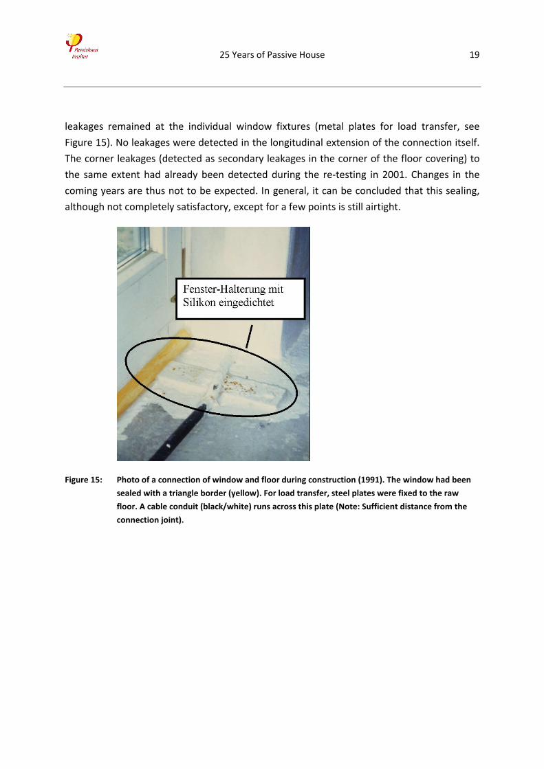
Figure 15: Photo of a connection of window and floor during construction (1991). The window had been
sealed with a triangle border (yellow). For load transfer, steel plates were fixed to the raw
floor. A cable conduit (black/white) runs across this plate (Note: Sufficient distance from the
connection joint).
25 Years of Passive House 20
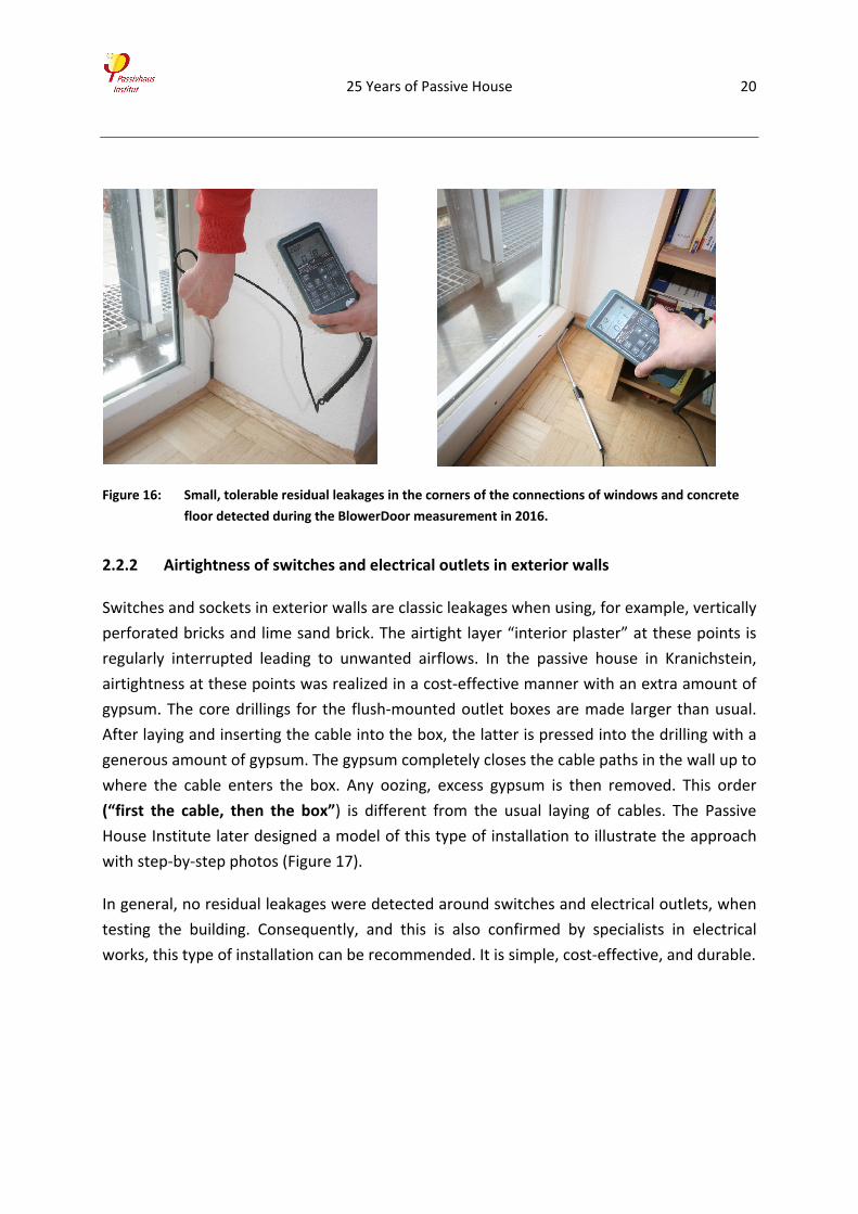
Figure 16: Small, tolerable residual leakages in the corners of the connections of windows and concrete
floor detected during the BlowerDoor measurement in 2016.
2.2.2 Airtightness of switches and electrical outlets in exterior walls
Switches and sockets in exterior walls are classic leakages when using, for example, vertically
perforated bricks and lime sand brick. The airtight layer “interior plaster” at these points is
regularly interrupted leading to unwanted airflows. In the passive house in Kranichstein,
airtightness at these points was realized in a cost‐effective manner with an extra amount of
gypsum. The core drillings for the flush‐mounted outlet boxes are made larger than usual.
After laying and inserting the cable into the box, the latter is pressed into the drilling with a
generous amount of gypsum. The gypsum completely closes the cable paths in the wall up to
where the cable enters the box. Any oozing, excess gypsum is then removed. This order
(“first the cable, then the box”) is different from the usual laying of cables. The Passive
House Institute later designed a model of this type of installation to illustrate the approach
with step‐by‐step photos (Figure 17).
In general, no residual leakages were detected around switches and electrical outlets, when
testing the building. Consequently, and this is also confirmed by specialists in electrical
works, this type of installation can be recommended. It is simple, cost‐effective, and durable.
25 Years of Passive House 21
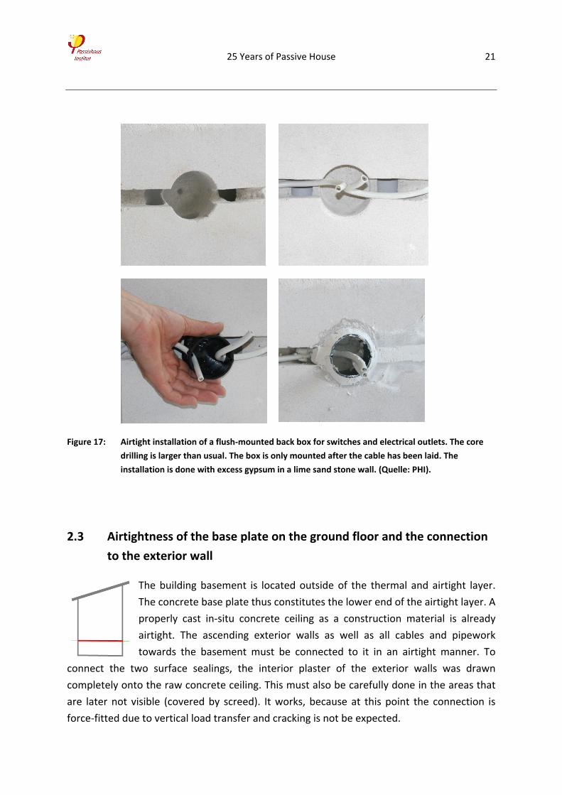
Figure 17: Airtight installation of a flush‐mounted back box for switches and electrical outlets. The core
drilling is larger than usual. The box is only mounted after the cable has been laid. The
installation is done with excess gypsum in a lime sand stone wall. (Quelle: PHI).
2.3 Airtightness of the base plate on the ground floor and the connection
to the exterior wall
The building basement is located outside of the thermal and airtight layer.
The concrete base plate thus constitutes the lower end of the airtight layer. A
properly cast in‐situ concrete ceiling as a construction material is already
airtight. The ascending exterior walls as well as all cables and pipework
towards the basement must be connected to it in an airtight manner. To
connect the two surface sealings, the interior plaster of the exterior walls was drawn
completely onto the raw concrete ceiling. This must also be carefully done in the areas that
are later not visible (covered by screed). It works, because at this point the connection is
force‐fitted due to vertical load transfer and cracking is not be expected.
25 Years of Passive House 22
All penetrations for cable and pipe work were filled with liquid anhydrate during the
construction phase. When drying, this filler expands and in doing so also seals small gaps.
This makes it an easy, safe, and cost‐effective solution for horizontal sealings.
During the search for leakages 25 years after construction at 50 Pa negative pressure, no
significant leakages at the connections of exterior walls and base plate or at the penetrations
could be detected. Accordingly, the sealings can definitely be considered durable.
2.4 Replacing window and door seals
The airtightness test 10 years after construction (2001) had already shown that the main
leakages were to be found between the blind frame and the window sash. Most of these
leakages were easily eliminated by a readjustment (increasing or equalizing surface
pressure). Window manufacturers generally recommend such a regular readjustment, but it
is often not done.
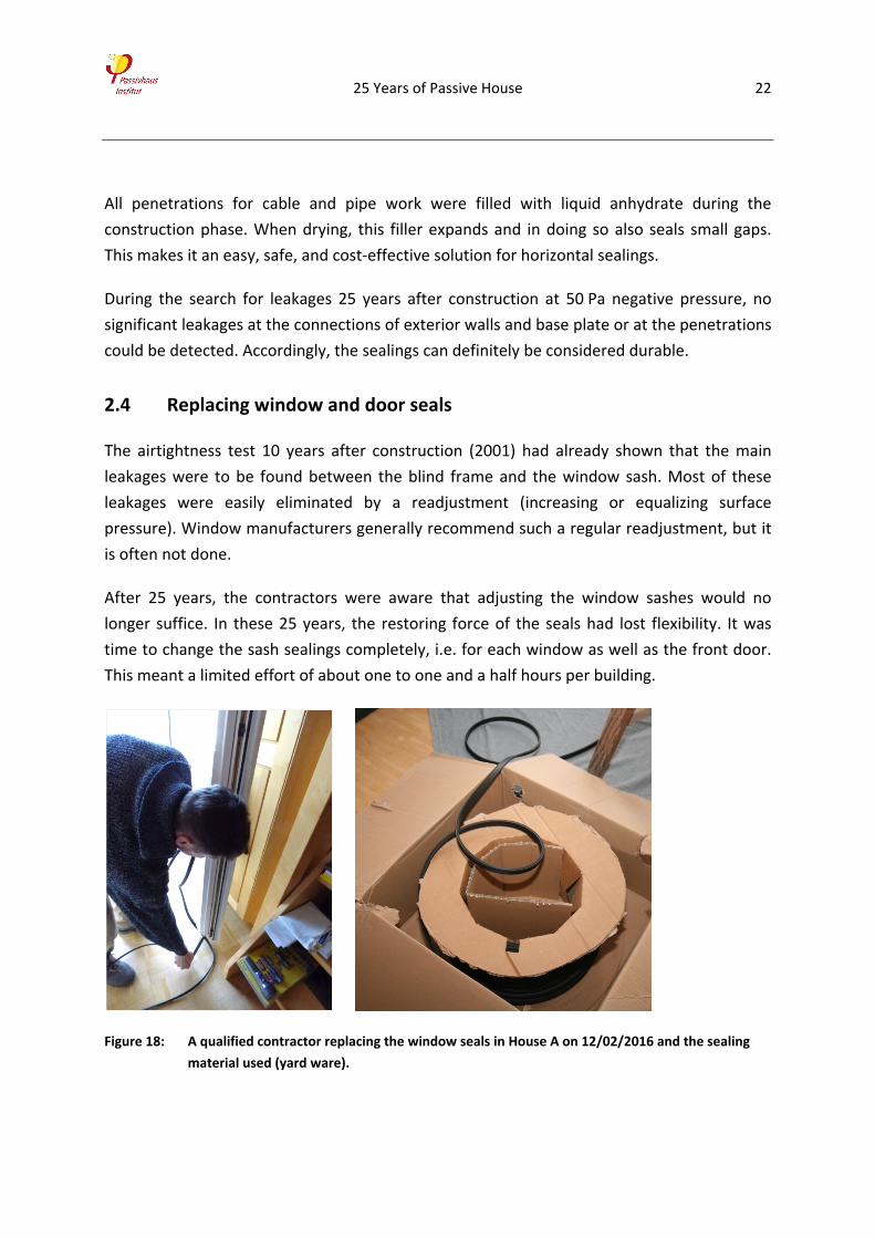
After 25 years, the contractors were aware that adjusting the window sashes would no
longer suffice. In these 25 years, the restoring force of the seals had lost flexibility. It was
time to change the sash sealings completely, i.e. for each window as well as the front door.
This meant a limited effort of about one to one and a half hours per building.
Figure 18: A qualified contractor replacing the window seals in House A on 12/02/2016 and the sealing
material used (yard ware).
25 Years of Passive House 23
2.5 Long‐term test of airtightness – Measuring results
The results from the pressure tests of the four units of the first passive house in 1991, were
exceptionally good. All four houses showed low n50‐values between 0.2 and 0.4 h–1. Not even
the experts had believed this to be possible. This was proof that an explicit airtightness
design can bring the desired success.
Table 2: Measuring results from the pressure test of the first BlowerDoor measurement on 24/25 of
May 1991 of the four units of the first passive house in Darmstadt Kranichstein.
Measurement n50-air change
during pressure test [h-1]
House A 0.24
House B 0.28
House C 0.26
House D 0.40
House A, front door taped closed 0.25
House C, one window on the ground floor tilted open
12.89
It had obviously not been clear from the beginning, how durable the materials used and the
connections implemented would be. The objective had been to ensure a durable, high
airtightness of the building for its whole lifetime. Therefore, the pressure tests in two of the
four houses had been repeated several times over the years (see also [Peper et al. 2005]). In
those tests, the results could be reproduced without any problem.
In each of the current tests, as in the previous measurements, the ventilation ducts were
sealed directly at the supply and exhaust air at the ventilation unit in the basement. Possible
residual leakages of the ventilation system (ducts and unit with heat exchanger) are also
measured when selecting these locations for sealing, i.e. are included in the measuring
result. For the measurements, the pressure test fan in each house was installed in a terrace
door in the living room. The measurements were conducted in compliance with German and
European Industrial Standard Din EN 13829 with a series of depressurization and
pressurization measurements. The pressure test protocols of the measurements after the
replacement of the seals are documented in the appendix.
25 Years of Passive House 24
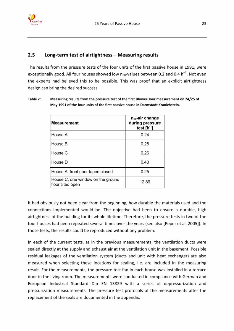
Figure 19: Left: The first pressure test was conducted on 24/26 of May 1991 by Ingenieurbüro ebök once
the airtight envelope had been finished.
Right: The current BlowerDoor Test (here in House B) was conducted on 11/12 of Feburary
2016 by the PHI 25 years after construction.
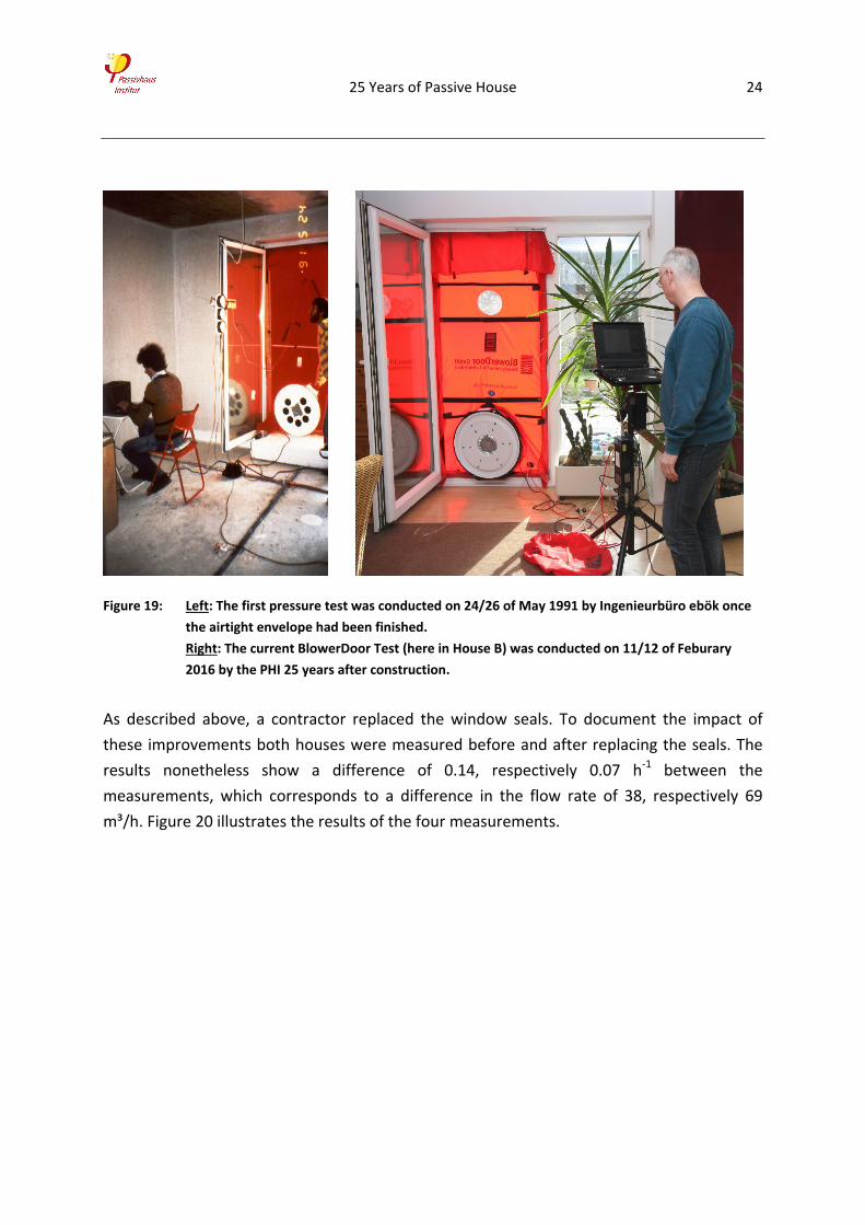
As described above, a contractor replaced the window seals. To document the impact of
these improvements both houses were measured before and after replacing the seals. The
results nonetheless show a difference of 0.14, respectively 0.07 h‐1 between the
measurements, which corresponds to a difference in the flow rate of 38, respectively 69
m³/h. Figure 20 illustrates the results of the four measurements.
25 Years of Passive House 25
Figure 20: Airtightness tests of the passive house in Kranichstein (Houses A and B) in February 2016, 25
years after construction, before and after replacing the window and door seals.
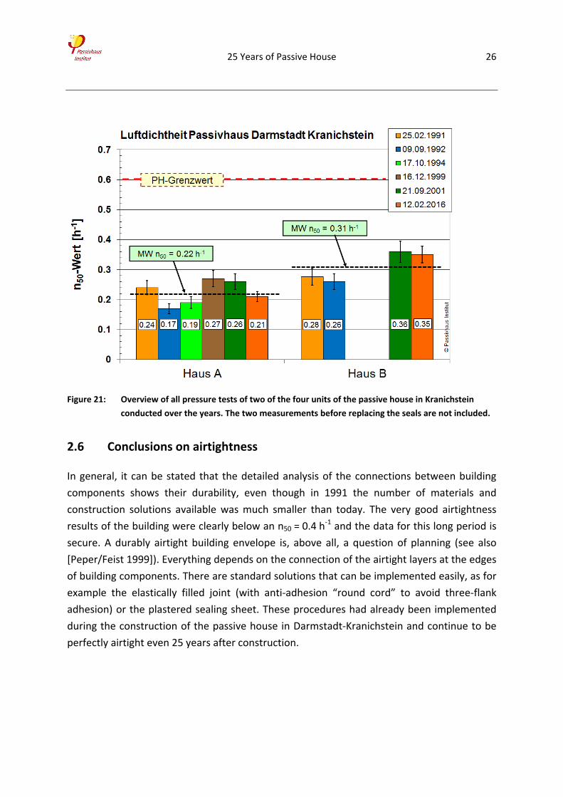
The current measurement, 25 years after construction, continues to show extremely good
results for airtightness. The only deterioration worth mentioning in both houses can be
assigned to the aging of the seals in the openable wings of windows and doors. It is a normal
process that the restoring force of the seals decreases after 25 years. (Therefore, lip seals
are replacement parts that can be changed easily.) In both houses, the measure led to a
significant reduction, in House IV it was even possible to reestablish the original value. With
an n50 = 0.21, respectively 0.35 h–1 the good results of the previous measurements were
repeated. Figure 21 gives an overview of all measuring results of the two units of the first
passive house.
25 Years of Passive House 26
Figure 21: Overview of all pressure tests of two of the four units of the passive house in Kranichstein
conducted over the years. The two measurements before replacing the seals are not included.
2.6 Conclusions on airtightness
In general, it can be stated that the detailed analysis of the connections between building
components shows their durability, even though in 1991 the number of materials and
construction solutions available was much smaller than today. The very good airtightness
results of the building were clearly below an n50 = 0.4 h‐1 and the data for this long period is
secure. A durably airtight building envelope is, above all, a question of planning (see also
[Peper/Feist 1999]). Everything depends on the connection of the airtight layers at the edges
of building components. There are standard solutions that can be implemented easily, as for
example the elastically filled joint (with anti‐adhesion “round cord” to avoid three‐flank
adhesion) or the plastered sealing sheet. These procedures had already been implemented
during the construction of the passive house in Darmstadt‐Kranichstein and continue to be
perfectly airtight even 25 years after construction.
25 Years of Passive House 27
3 Summary and conclusions
3.1 Main findings
The first occupants moved into the first passive house in Darmstadt‐Kranichstein in 1991. The
pioneers had ventured far. A house with normal occupancy and use, a high level of thermal
comfort, and durably excellent air quality while keeping energy consumption at a minimum.
They can now look back at 25 years of use of the row of terraced houses with its four units. In
2026, it was once again time to test the components and the overall function in detail.
The original, pioneering research project on the building from 1988 to 1995 included the
research and development preparing construction, construction itself, and a comprehensive
program of measurements during regular use financed by the Hessian Ministry for the
Environment and Ministry of Economics, as well as the Wüstenrot Foundation. It not only
focused on the consumption data, but also included temperature profiles for the exterior
and the interior as well as in building components, humidity development, efficiency of
ventilation systems, energy supply (natural gas and electricity), comparison with the results
of the dynamic simulation, airtight measurements, air quality measurements in the interior
and ventilation systems, and a sociological analysis, all of them over a period of several
years.
The purpose of the present study is now to test the functionality and performance of the
building and its individual components after a longer period. The analysis focused on
characteristics whose durability is not always to be expected or about which questions had
had been raised in scientific and public discourse.
25 Years of Passive House 28
Here the main results of the extensive analysis:
Energy consumption
The consumption data for the
whole operating life remains
consistently low.
Heating demand is the main
indicator for the thermal
quality of the entire building
and was the main target
criterion for the project.
Except for slight climate‐
based variations, the heating
energy consumption over the
25 years remains low. The gas consumption for heating measured on average is only 8.4
kWh/(m²a), i.e. approximately one sixteenth of the average for residential buildings in
Germany. This energy consumption is even slightly lower than the value predicted in the pre‐
construction simulations. The project thus also validates the recognized calculation methods
from building physics and their consistently reliable usability.
The development of the energy balance tool PHPP today allows for reliable calculations
during the planning phase also with simpler tools so that any planning team can design
highly efficient, and from the point of building physics, flawless buildings and predetermine
their behavior.
Roof structure
The roof is “green” and not ventilated. It was therefore interesting to check long‐term
humidity development.
• Even after 25 years, the measured values remain acceptable. Highly thermally insulated
roofs as implemented in the pilot project can consequently be used long‐term and are
durable. However, contrary to the conventional vapor barrier used in the pilot project,
the use of moisture‐adaptive vapor barriers is recommended. Over long periods, they
allow you to achieve even lower levels of humidity. Reliably durable airtightness is a
critical factor for the long‐term functioning of an unventilated roof structure. The re‐
measurements have shown that the methods chosen here, allow you to implement
25 Years of Passive House 29
airtightness reliably (continuous sealing sheets, plastering of the sheets into the interior
plaster of the adjacent solid building parts).
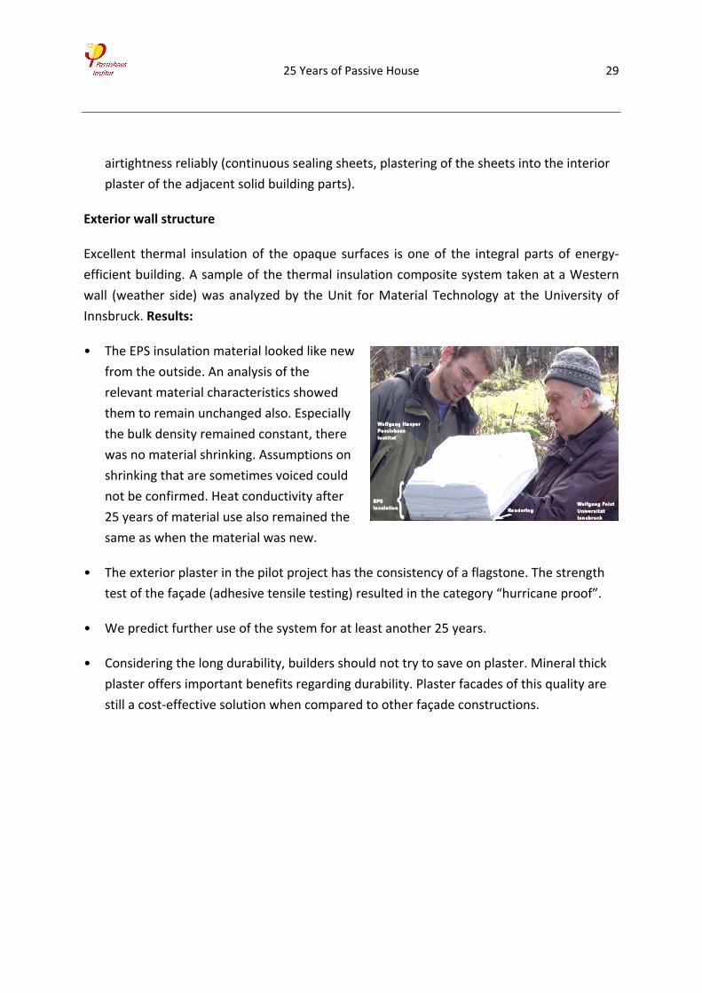
Exterior wall structure
Excellent thermal insulation of the opaque surfaces is one of the integral parts of energy‐
efficient building. A sample of the thermal insulation composite system taken at a Western
wall (weather side) was analyzed by the Unit for Material Technology at the University of
Innsbruck. Results:
• The EPS insulation material looked like new
from the outside. An analysis of the
relevant material characteristics showed
them to remain unchanged also. Especially
the bulk density remained constant, there
was no material shrinking. Assumptions on
shrinking that are sometimes voiced could
not be confirmed. Heat conductivity after
25 years of material use also remained the
same as when the material was new.
• The exterior plaster in the pilot project has the consistency of a flagstone. The strength
test of the façade (adhesive tensile testing) resulted in the category “hurricane proof”.
• We predict further use of the system for at least another 25 years.
• Considering the long durability, builders should not try to save on plaster. Mineral thick
plaster offers important benefits regarding durability. Plaster facades of this quality are
still a cost‐effective solution when compared to other façade constructions.
25 Years of Passive House 30
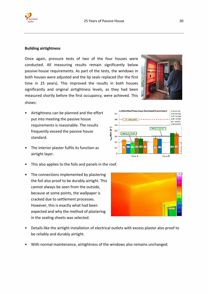
Building airtightness
Once again, pressure tests of two of the four houses were
conducted. All measuring results remain significantly below
passive‐house requirements. As part of the tests, the windows in
both houses were adjusted and the lip seals replaced (for the first
time in 25 years). This improved the results in both houses
significantly and original airtightness levels, as they had been
measured shortly before the first occupancy, were achieved. This
shows:
• Airtightness can be planned and the effort
put into meeting the passive house
requirements is reasonable. The results
frequently exceed the passive house
standard.
• The interior plaster fulfils its function as
airtight layer.
• This also applies to the foils and panels in the roof.
• The connections implemented by plastering
the foil also proof to be durably airtight. This
cannot always be seen from the outside,
because at some points, the wallpaper is
cracked due to settlement processes.
However, this is exactly what had been
expected and why the method of plastering
in the sealing sheets was selected.
• Details like the airtight installation of electrical outlets with excess plaster also proof to
be reliably and durably airtight.
• With normal maintenance, airtightness of the windows also remains unchanged.
25 Years of Passive House 31
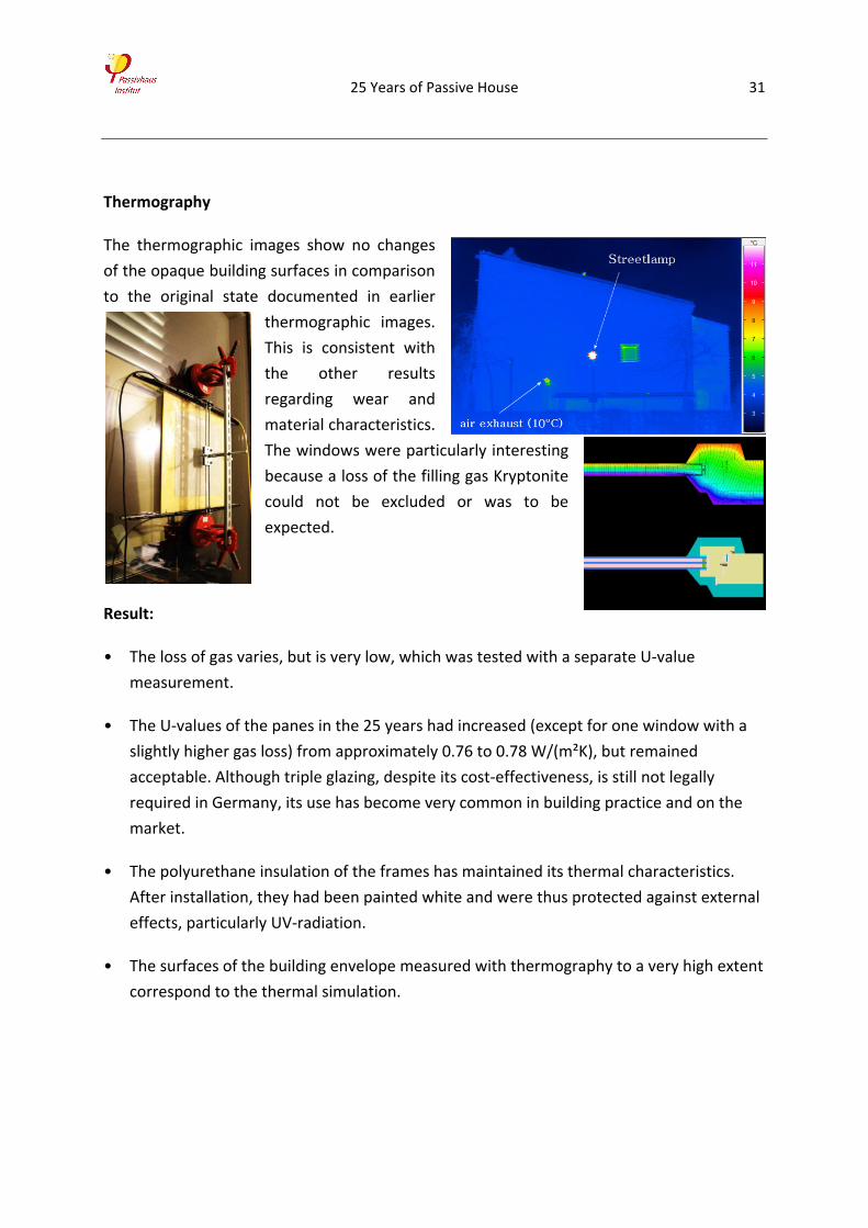
Thermography
The thermographic images show no changes
of the opaque building surfaces in comparison
to the original state documented in earlier
thermographic images.
This is consistent with
the other results
regarding wear and
material characteristics.
The windows were particularly interesting
because a loss of the filling gas Kryptonite
could not be excluded or was to be
expected.
Result:
• The loss of gas varies, but is very low, which was tested with a separate U‐value
measurement.
• The U‐values of the panes in the 25 years had increased (except for one window with a
slightly higher gas loss) from approximately 0.76 to 0.78 W/(m²K), but remained
acceptable. Although triple glazing, despite its cost‐effectiveness, is still not legally
required in Germany, its use has become very common in building practice and on the
market.
• The polyurethane insulation of the frames has maintained its thermal characteristics.
After installation, they had been painted white and were thus protected against external
effects, particularly UV‐radiation.
• The surfaces of the building envelope measured with thermography to a very high extent
correspond to the thermal simulation.
25 Years of Passive House 32
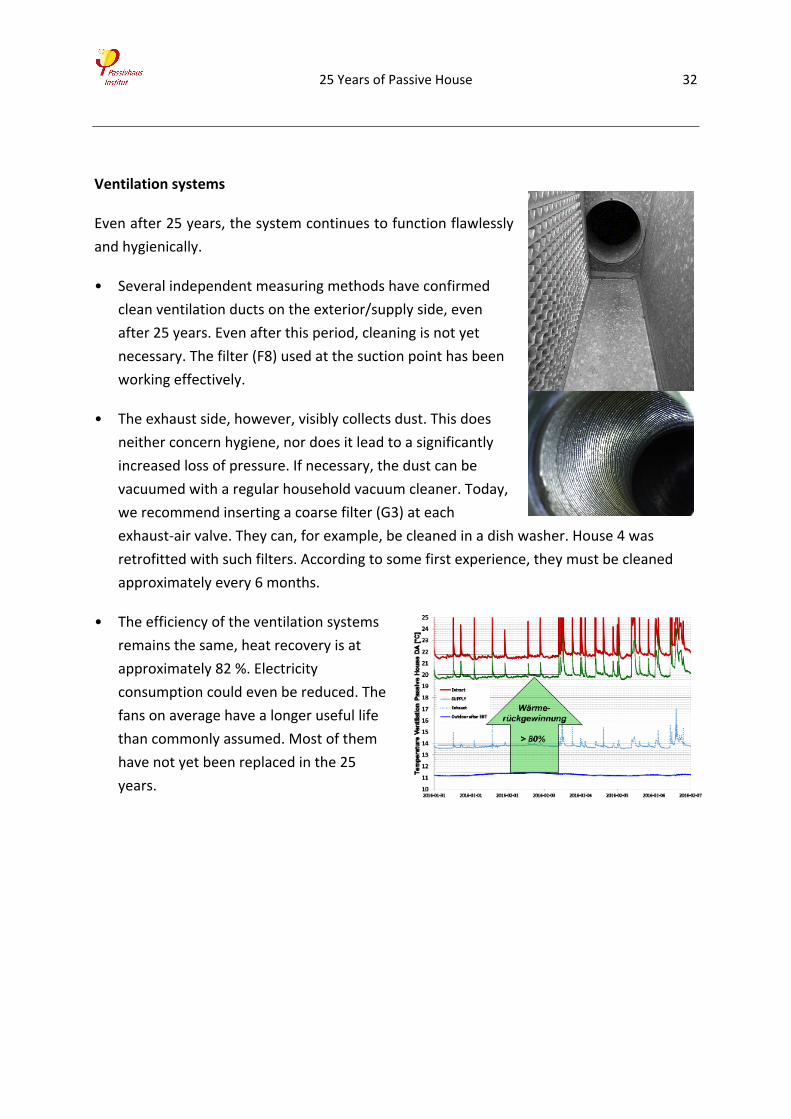
Ventilation systems
Even after 25 years, the system continues to function flawlessly
and hygienically.
• Several independent measuring methods have confirmed
clean ventilation ducts on the exterior/supply side, even
after 25 years. Even after this period, cleaning is not yet
necessary. The filter (F8) used at the suction point has been
working effectively.
• The exhaust side, however, visibly collects dust. This does
neither concern hygiene, nor does it lead to a significantly
increased loss of pressure. If necessary, the dust can be
vacuumed with a regular household vacuum cleaner. Today,
we recommend inserting a coarse filter (G3) at each
exhaust‐air valve. They can, for example, be cleaned in a dish washer. House 4 was
retrofitted with such filters. According to some first experience, they must be cleaned
approximately every 6 months.
• The efficiency of the ventilation systems
remains the same, heat recovery is at
approximately 82 %. Electricity
consumption could even be reduced. The
fans on average have a longer useful life
than commonly assumed. Most of them
have not yet been replaced in the 25
years.
25 Years of Passive House 33
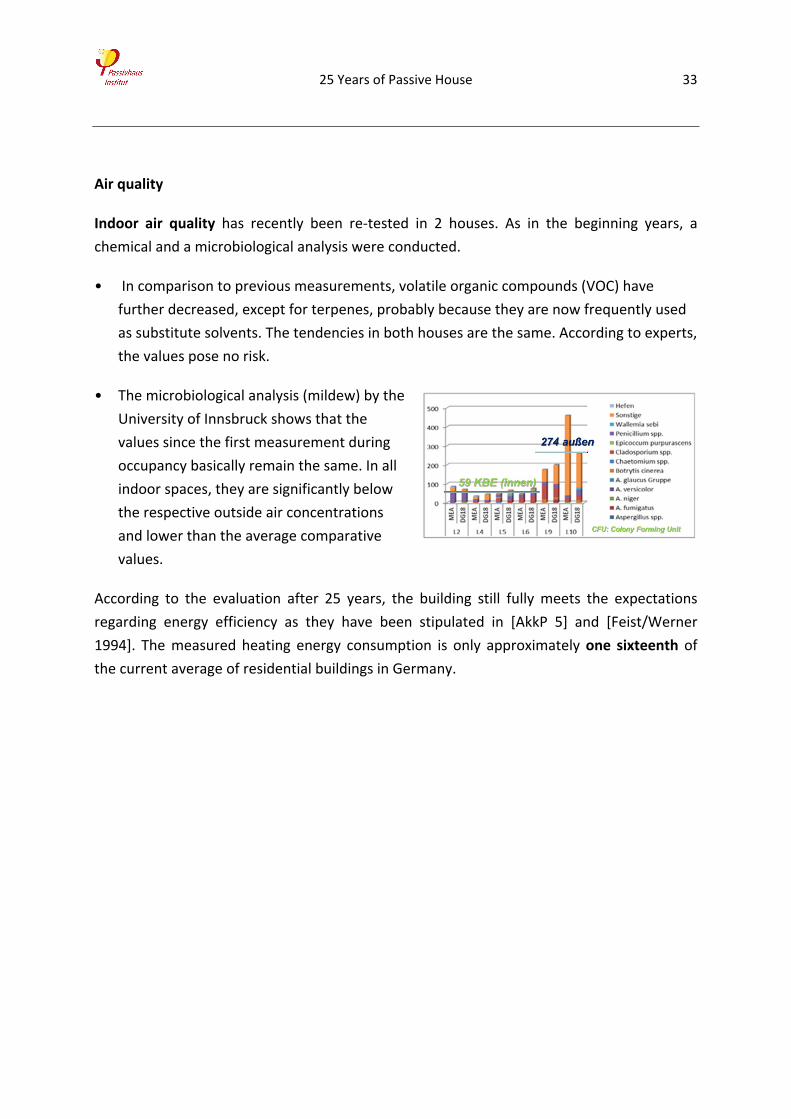
Air quality
Indoor air quality has recently been re‐tested in 2 houses. As in the beginning years, a
chemical and a microbiological analysis were conducted.
• In comparison to previous measurements, volatile organic compounds (VOC) have
further decreased, except for terpenes, probably because they are now frequently used
as substitute solvents. The tendencies in both houses are the same. According to experts,
the values pose no risk.
• The microbiological analysis (mildew) by the
University of Innsbruck shows that the
values since the first measurement during
occupancy basically remain the same. In all
indoor spaces, they are significantly below
the respective outside air concentrations
and lower than the average comparative
values.
According to the evaluation after 25 years, the building still fully meets the expectations
regarding energy efficiency as they have been stipulated in [AkkP 5] and [Feist/Werner
1994]. The measured heating energy consumption is only approximately one sixteenth of
the current average of residential buildings in Germany.
25 Years of Passive House 34
4 References
[AkkP 3] „Superfenster im Passivhaus“; Arbeitskreis kostengünstige Passivhäuser Phase II, Protokollband Nr. 3.
Passivhaus Institut, Darmstadt, 1996.
[AkkP 4] „Lüftung im Passivhaus“; Protokollband Nr. 4 des Arbeitskreises kostengünstige Passivhäuser, 1.
Auflage, Passivhaus Institut, Darmstadt 1997
[AkkP 5] „Energiebilanz und Temperaturverhalten – mit Messergebnissen aus dem Passivhaus Darmstadt
Kranichstein“. Protokollband Nr. 5 des Arbeitskreises kostengünstige Passivhäuser, 1. Auflage, Passivhaus
Institut, Darmstadt 1997
[AkkP 6] „Messung und Messergebnisse“. Protokollband Nr. 5 des Arbeitskreises kostengünstige Passivhäuser,
1. Auflage, Passivhaus Institut, Darmstadt 1997
[AkkP 8] „Materialwohl, Ökologie und Raumlufthygiene“. Protokollband Nr. 8 des Arbeitskreises
kostengünstige Passivhäuser, 1. Auflage, Passivhaus Institut, Darmstadt 1997
[AkkP 9] „Nutzerverhalten“; Protokollband Nr. 5 des Arbeitskreises kostengünstige Passivhäuser, 1. Auflage,
Passivhaus Institut, Darmstadt 1997
[AkkP 10] „Messtechnik und Messergebnisse“. Arbeitskreis kostengünstige Passivhäuser 10, PHI, Darmstadt
1997, 3. Auflage 2009
[AkkP 13] „Energiebilanzen mit dem Passivhaus Projektierungs Paket“; Protokollband Nr. 13 des Arbeitskreises
kostengünstige Passivhäuser, 1. Auflage, Passivhaus Institut, Darmstadt 1998
[AkkP 14] „Passivhaus‐Fenster“; Protokollband Nr. 14 des Arbeitskreises kostengünstige Passivhäuser, 1.
Auflage, Passivhaus Institut, Darmstadt 1998
[AkkP 16] „Wärmebrückenfreies Konstruieren“; Protokollband Nr. 16 des Arbeitskreises kostengünstige
Passivhäuser. Passivhaus Institut, Darmstadt, 1999
[AkkP 22] „Lüftungsstrategien für den Sommer“. Arbeitskreis kostengünstige Passivhäuser 22, PHI, Darmstadt
2003, 2. Auflage 2011
[AkkP 45] „Richtig messen in Energiesparhäusern“. Protokollband Nr 45 des Arbeitskreise kostengünstige
Passivhäuser, Darmstadt 2012
[BGA 1986] B. Seifert et al.: „Flüchtige organische Verbindungen in der Innenraumluft“; Bundes‐
gesundheitsblatt 29 (1986) 417
[CEPHEUS 2001] J. Schnieders, W. Feist, R. Pfluger, O. Kah: „CEPHEUS ‐ cost efficient passive houses as
european standards – Wissenschaftliche Begleitung und Auswertung Endbericht“. Passivhaus Institut,
Darmstadt 2001; 2. Auflage 2007
[Component Award 2014] Wettbewerb Passivhausfenster, auf der 18. Internationalen Passivhaustagung in
Aachen, 2014.
[designPH] Passivhaus Institut, DesignPH: 3‐D Eingabetool für das PHPP basierend auf Trimble SketchUp,
Darmstadt/Innsbruck, 2016
25 Years of Passive House 35
[Ebel/Feist 1997] W. Ebel und W. Feist: "Ergebnisse zum Stromverbrauch im Passivhaus Darmstadt
Kranichstein" in "Stromsparen im Passivhaus"; Protokollband Nr. 7 zum Arbeitskreis Kostengünstige
Passivhäuser; PHI; Darmstadt, 1997.
[ETAG 2013] European Organisation for Technical Approvals: ETAG 004, Edition 2000, Amended August 2011,
Amended February 2013. “GUIDELINE FOR EUROPEAN TECHNICAL APPROVAL of EXTERNAL THERMAL
INSULATION COMPOSITE SYSTEMS (ETICS) WITH RENDERING”, Brussels 2013
[Fanger 1970] P.O. Fanger: “Thermal Comfort. Analysis and Applications in Environmental Engineering”; USA:
New York 1972, © P.O. Fanger 1970
[Feist 1988a] W. Feist et al: „Das Niedrigenergiehaus“. C.F.Müller Verlag, 1. Auflage Heidelberg 1988, 5. Auflage
Karlsruhe 1998
[Feist 1988b] W. Feist: „Forschungsprojekt Passive Häuser, Projektziele ‐ mit einem Kommentar des Autors“ zur
2. Auflage 1995, Institut Wohnen und Umwelt, Darmstadt, 1. Aufl. 1988, 2. Aufl. 1995
[Feist 1992] W. Feist: „Passivhaus Darmstadt Kranichstein“. In: Bundesbaublatt, Februar 1992
[Feist 1993] W. Feist: „Passivhäuser in Mitteleuropa“; Dissertation, Universität Kassel, 1993
[Feist 1994a] W. Feist, M. Bially, W. Eicke‐Hennig, T. Loga, M. Lüneburg, J. Militzer: „Wirtschaftlichkeit von
Niedrigenergiehäusern“. In Sonnenenergie und Wärmetechnik, 4/1994
[Feist 1994b] W. Feist: „Thermische Gebäudesimulation“. C.F.Müller Verlag, Heidelberg 1994
[Feist 1995] W. Feist (Hrsg.): „Luftqualität im Passivhaus“. Institut Wohnen und Umwelt, Darmstadt 1995
[Feist 1995a] W. Feist: „Die Luftdichtheit im Passivhaus“, Passivhaus‐Bericht Nr. 6, Institut Wohnen und
Umwelt GmbH, Darmstadt 1995.
[Feist 1995b] Hrsg.: W. Feist. Autoren: J. Battenberg, W. Feist, A. Fingerling, K.‐H. Fingerling, J. Werner, P.
Kühnle, U. Rochard, J. Zeller. „Gedämmte Fensterläden im Passivhaus“ Passivhaus‐Bericht Nr. 9, Institut
Wohnen und Umwelt, Darmstadt 1995
[Feist 1997a] W. Feist, T. Loga: "Vergleich von Messung und Simulation" in "Energiebilanz und
Temperaturverhalten"; [AkkP 5]; PHI; Darmstadt, Januar 1997.
[Feist 1997b] W. Feist: "Der Härtetest: Passivhäuser im strengen Winter 1996/97"; GRE‐Inform, 12/1997.
[Feist 1997c] W. Feist: "Passivhaus Darmstadt Kranichstein ‐ Planung, Bau, Ergebnisse", Fachinformation PHI
1997/4, 1. Auflage, 16 Seiten, Darmstadt 1997
[Feist 1997e] W. Feist: „Ergebnisse der Luftqualitätsmessungen im Passivhaus Darmstadt Kranichstein“. In:
Arbeitskreis kostengünstige Passivhäuser, Protokollband Nr. 8: Materialwahl und Raumlufthygiene. Passivhaus
Institut, Darmstadt 1997
[Feist 2000] W. Feist: "Erfahrungen objektiv: Messergebnisse aus bewohnten Passivhäusern"; in: Tagungsband
zur 4. Passivhaus Tagung in Kassel. Passivhaus Dienstleistung GmbH, 1. Auflage, Darmstadt 2000
25 Years of Passive House 36
[Feist 2005] W. Feist: „Heizlast in Passivhäusern – Validierung durch Messungen“; Endbericht IEA SHC TASK 28 /
ECBCS ANNEX 38, Forschungsvorhaben im Rahmen der nationalen Beteiligung an der Arbeitsgruppe
‚Sustainable Solar Housing’ der Internationalen Energie Agentur IEA, Subtask B: Design und Analyse, Darmstadt,
2005.
[Feist et al. 2016] W. Feist, W. Ebel, S. Peper, W. Hasper: „Langzeiterfahrungen und Messergebnisse aus dem
ersten Passivhaus in Darmstadt‐Kranichstein“. In: Tagungsband zur 20. Internationale Passivhaustagung 2016,
Passivhaus Institut Darmstadt, 2016
[Feist/Holtmann 1998] W. Feist; K. Holtmann: „Erhöhter Glaseinstand kann Gefahr von thermisch induzierten
Scheibensprüngen reduzieren“. In: gff 5/98, Zeitschrift für Glas, Fenster, Fassade. Verlag Karl Hofmann,
Schorndorf, 1998
[Feist/Werner 1993] W. Feist; J. Werner: Erste Meßergebnisse aus dem Passivhaus Darmstadt Kranichstein; gi
Heft 5, Oktober 1993
[Feist/Werner 1994] W. Feist und J. Werner: "Gesamtenergiekennwert < 32 kWh/(m²a)"; Bundesbaublatt
2/1994
[Fingerling 1992] K.‐H. Fingerling: „Entwicklung, Entwurf und Bau von Prototypen für hochgedämmte
Fensterrahmen und hochdämmende Fensterläden“ In: Bauvorbereitendes Forschungsprojekt Passive Häuser,
Passivhaus Bericht Nr. 2, Institut Wohnen und Umwelt, Darmstadt 1992
[Grove‐Smith et al. 2016] J. Grove‐Smith; W. Feist; B. Krick: “Balancing Energy Efficiency and Renewables”. In:
Paolo Bertoldi (ed.): Proceedings of the 9th International Conference Improving Energy Efficiency in
Commercial Buildings and Smart Communities, EUR 27993 EN. European Union, 2016, p. 894‐902.
(doi:10.2790/290244)
[Grün 1995] L. Grün: „Untersuchungen zur Bewertung der Luftqualität im Passivhaus Darmstadt‐Kranichstein“.
In: [Feist 1995]
[Grün 1998] L. Grün: „Luftqualität im Passivhaus“; in: Tagungsband 2. Passivhaustagung Passivhaus Institut,
Darmstadt 1998
[Kirchmair 2016] M. Kirchmair: Laborbericht Nr. A‐2015/6127, Universität Innsbruck, Institut für Mikrobiologie,
Innsbruck 18.04.2016
[Kirtschig 1998] T. Kirtschig; J. Werner, W. Feist: „Thermische Behaglichkeit im Passivhaus Kranichstein“. IWU,
Darmstadt 1998
[Komponenten 2016] Zertifizierte Passivhauskomponenten im Internet. www.componentdatabase.org
[Pallantzas/Roditi 2016] S. Palantzas, Athanasia Roditi: “Passivistas: The House Project”, in Tagungsband zur
20. Passivhaus Tagung. Passivhaus Institut, Darmstadt 2016
[Passipedia] Passipedia; Die Online‐Wissensdatenbank für energieeffiziente Gebäude. PHI, Darmstadt 2010 –
2016. www.passipedia.de
[Peper et al. 2005] S. Peper; O. Kah; W. Feist: „Zur Dauerhaftigkeit von Luftdichtheitskonzepten bei
Passivhäusern“, Feldmessungen. Forschungsbericht im Rahmen vom IEA SHC TASK 28 / ECBCS ANNEX 38.
Passivhaus Institut, Darmstadt, Juni, 2005.
25 Years of Passive House 37
[Peper/Feist 1999] S. Peper; W. Feist: „Luftdichte Projektierung von Passivhäusern“, Fachinformation PHI‐
1999/6, Passivhaus Institut, Darmstadt 1999, 10. Auflage 2009
[PHPP] Passivhaus Projektierungs‐Paket. Berechnung von Energiebilanzen und Planungstool für
energieeffiziente Gebäude. Passivhaus Institut Darmstadt, Darmstadt 1998 ‐2016. Aktuelle Version: PHPP 9.6
(2016)
[PHT 1996] Tagungsband der 1. Passivhaustagung in Darmstadt, 22./23. November 1996. Passivhaus Institut,
Darmstadt, 1996
[RMI 2016] Dr. Robert Murjahn Institut, Prüfbericht_Q‐02016‐050‐029 Bestimmung der Haftzugfestigkeit
zwischen Putzschicht und EPS‐Dämmung an dem Objekt Carsonweg 82, 64289 Darmstadt‐Kranichstein, Ober‐
Ramstadt 2016 (unveröffentlicht)
[Rohrmann 1994] B. Rohrmann: "Sozialwissenschaftliche Evaluation des Passivhauses in Darmstadt";
Passivhaus‐Bericht Nr. 11; Institut Wohnen und Umwelt; Darmstadt, September 1994.
[Schnieders 2012] J. Schnieders: „Messgenauigkeiten und Fehlergrößen“. In: Protokollband Nr. 45 „Richtig
Messen in Energiesparhäusern“ des Arbeitskreises kostengünstige Passivhäuser, Passivhaus Institut, Darmstadt
2012
[UBA 2008] H. Hofmann, P. Plieninger: „Bereitstellung einer Datenbank zum Vorkommen von flüchtigen
organischen Verbindungen in der Raumluft“. Umweltbundesamt, Dessau 2008
[Varioscan] Kamerasystem VARIOSCAN high resolution 3021 ST, Hersteller: JENOPTIK / InfraTec
[Wörner, Bomhard 2014] D. Wörner, T. v. Bomhard et al: “Look Twice: Uncover Hidden Information in Room
Climate Sensor Data”; DOI: 10.1109/IOT.2014.7030110
[Zertifizierungskriterien Lüftung] Prüfreglement Lüftungsgeräte zentral, Stand 24.09.2009. Anforderungen und
Prüfverfahren zur energetischen und schalltechnischen Beurteilung von Passivhaus‐Lüftungsgeräten < 600
m³/h für die Zertifizierung als „Passivhaus geeignete Komponente“
For further information on the passive house project in Darmstadt Kranichstein
please consult
www.passivhaustagung.de/Kran/Passivhaus_Kranichstein.htm
or the knowledge database
www.passipedia.de
25 Years of Passive House 38
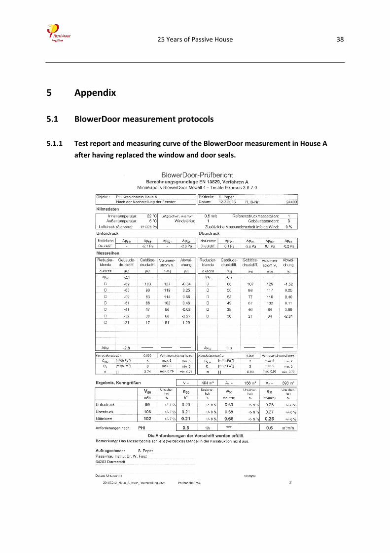
5 Appendix
5.1 BlowerDoor measurement protocols
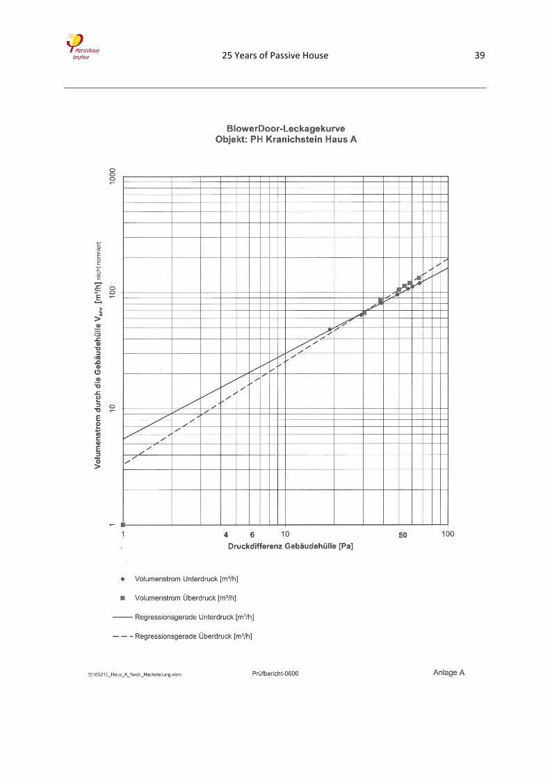
5.1.1 Test report and measuring curve of the BlowerDoor measurement in House A
after having replaced the window and door seals.
25 Years of Passive House 39
25 Years of Passive House 40
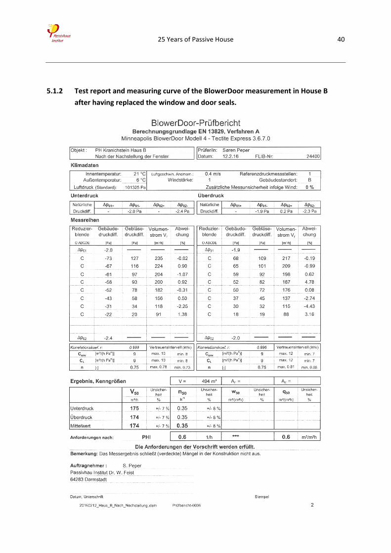
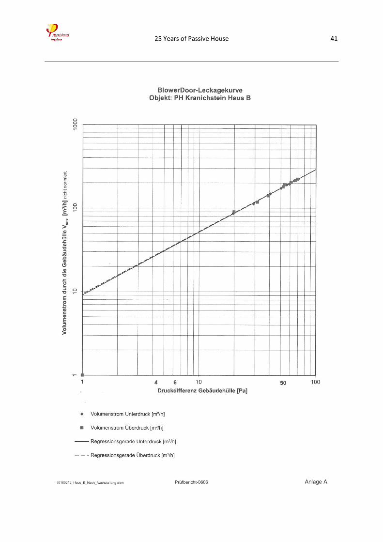
5.1.2 Test report and measuring curve of the BlowerDoor measurement in House B
after having replaced the window and door seals.
25 Years of Passive House 41