Embed Size (px)
Citation preview
TITLE
Image
25G Long Reach Cable Link System Equalization Optimization
Geoff Zhang (Xilinx Inc.)
Yu Liao (Xilinx), Echo Ma (Luxshare-ICT),
Jinhua Chen (Luxshare-ICT), Geoff Zhang (Xilinx)
25G Long Reach Cable Link System
Equalization Optimization
Geoff Zhang (Xilinx Inc.)
Yu Liao (Xilinx), Echo Ma (Luxshare-ICT),
Jinhua Chen (Luxshare-ICT), Geoff Zhang (Xilinx)

SPEAKERS
Geoff Zhang, SerDes Technology Group, Xilinx Inc.
Geoff Zhang received his Ph.D. in 1997 in microwave engineering and signal processing from Iowa State University, Ames, Iowa. He joined Xilinx Inc. in 2013 as director of architecture and modeling in the SerDes Technology Group. Prior to joining Xilinx he has employment experiences with HiSilicon, Huawei Technologies, LSI, Agere Systems, Lucent Technologies, and Texas Instruments. His current interest is in transceiver architecture modeling and system level end-to-end simulations, both electrical and optical.
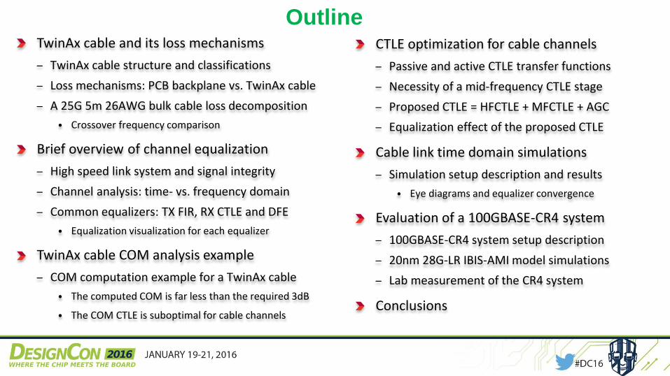
OutlineTwinAx cable and its loss mechanisms
– TwinAx cable structure and classifications
– Loss mechanisms: PCB backplane vs. TwinAx cable
– A 25G 5m 26AWG bulk cable loss decomposition
• Crossover frequency comparison
Brief overview of channel equalization
– High speed link system and signal integrity
– Channel analysis: time- vs. frequency domain
– Common equalizers: TX FIR, RX CTLE and DFE
• Equalization visualization for each equalizer
TwinAx cable COM analysis example
– COM computation example for a TwinAx cable
• The computed COM is far less than the required 3dB
• The COM CTLE is suboptimal for cable channels
CTLE optimization for cable channels
– Passive and active CTLE transfer functions
– Necessity of a mid-frequency CTLE stage
– Proposed CTLE = HFCTLE + MFCTLE + AGC
– Equalization effect of the proposed CTLE
Cable link time domain simulations
– Simulation setup description and results
• Eye diagrams and equalizer convergence
Evaluation of a 100GBASE-CR4 system
– 100GBASE-CR4 system setup description
– 20nm 28G-LR IBIS-AMI model simulations
– Lab measurement of the CR4 system
Conclusions
TwinAx Cable and its
Loss Mechanisms
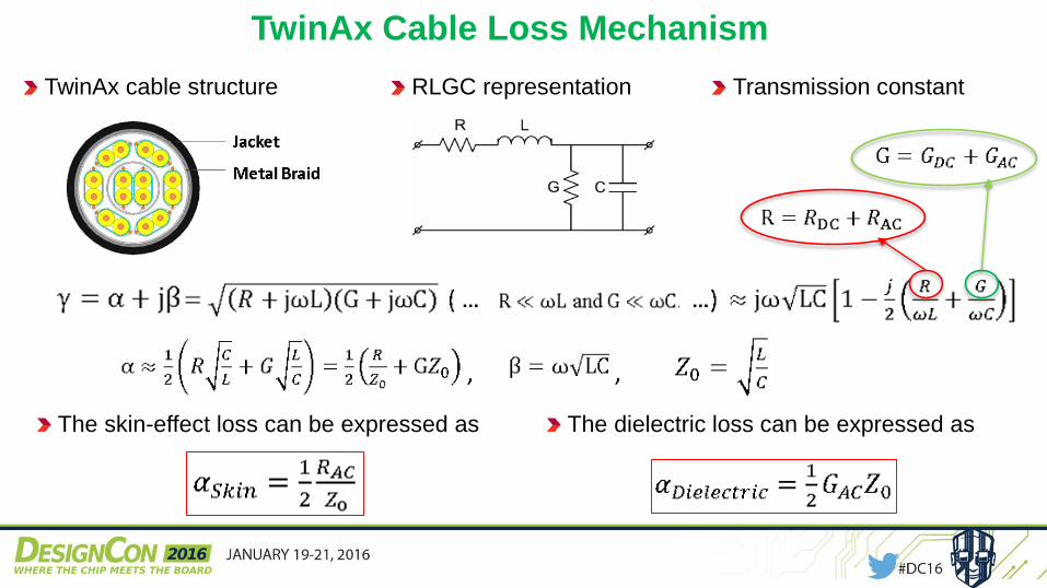
TwinAx Cable Loss Mechanism
The skin-effect loss can be expressed as
TwinAx cable structure RLGC representation Transmission constant
The dielectric loss can be expressed as
, ,
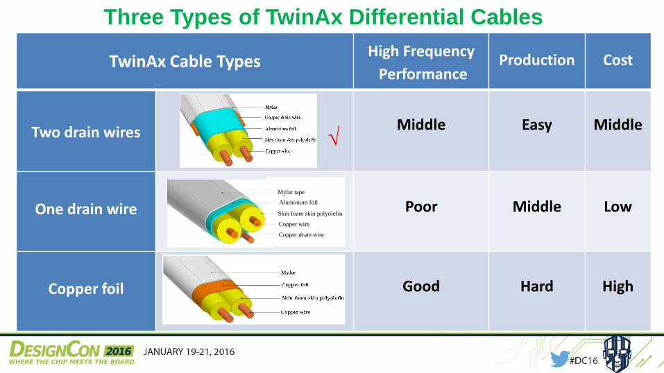
Three Types of TwinAx Differential Cables
assembliesTwinAx Cable Types
High Frequency
PerformanceProduction Cost
Two drain wires Middle Easy Middle
One drain wire Poor Middle Low
Copper foil Good Hard High
Copper wire
Aluminium foil
Copper drain wire
Skin foam skin polyolefin
Mylar tape
√
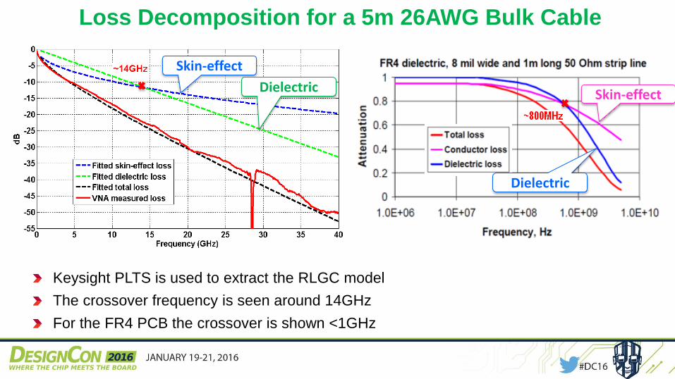
Loss Decomposition for a 5m 26AWG Bulk Cable
Keysight PLTS is used to extract the RLGC model
The crossover frequency is seen around 14GHz
For the FR4 PCB the crossover is shown <1GHz
Skin-effect
Dielectric Skin-effect
Dielectric
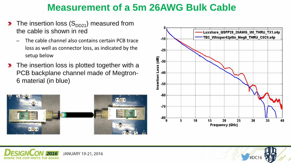
Measurement of a 5m 26AWG Bulk Cable
The insertion loss (SDD21) measured from
the cable is shown in red
‒ The cable channel also contains certain PCB trace
loss as well as connector loss, as indicated by the
setup below
The insertion loss is plotted together with a
PCB backplane channel made of Megtron-
6 material (in blue)
Brief Overview of
Channel Equalization
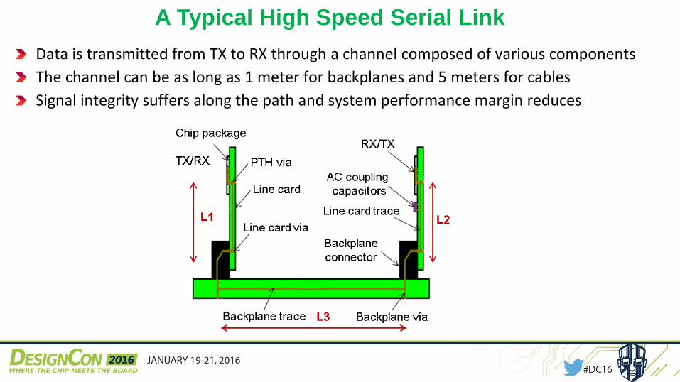
A Typical High Speed Serial Link
Data is transmitted from TX to RX through a channel composed of various components
The channel can be as long as 1 meter for backplanes and 5 meters for cables
Signal integrity suffers along the path and system performance margin reduces
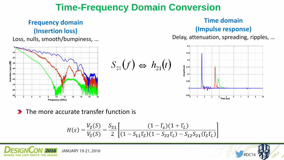
Time-Frequency Domain Conversion
Frequency domain(Insertion loss)
Loss, nulls, smooth/bumpiness, …
The more accurate transfer function is
Time domain(Impulse response)
Delay, attenuation, spreading, ripples, …
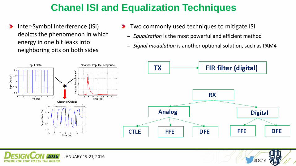
Chanel ISI and Equalization Techniques
Inter-Symbol Interference (ISI) depicts the phenomenon in which energy in one bit leaks into neighboring bits on both sides
Two commonly used techniques to mitigate ISI
‒ Equalization is the most powerful and efficient method
‒ Signal modulation is another optional solution, such as PAM4
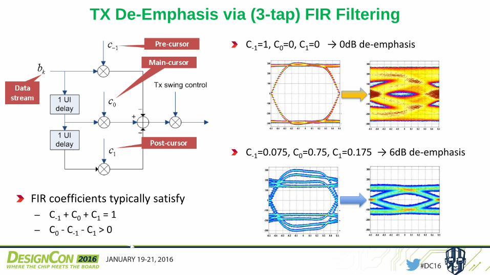
TX De-Emphasis via (3-tap) FIR Filtering
FIR coefficients typically satisfy
‒ C-1 + C0 + C1 = 1
‒ C0 - C-1 - C1 > 0
C-1=1, C0=0, C1=0 → 0dB de-emphasis
C-1=0.075, C0=0.75, C1=0.175 → 6dB de-emphasis
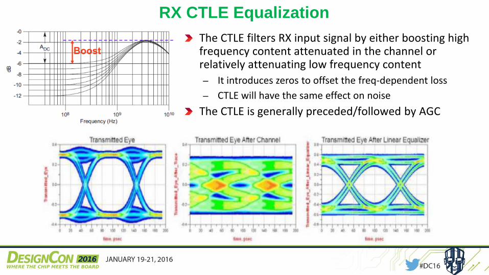
RX CTLE Equalization
The CTLE filters RX input signal by either boosting high frequency content attenuated in the channel or relatively attenuating low frequency content
‒ It introduces zeros to offset the freq-dependent loss
‒ CTLE will have the same effect on noise
The CTLE is generally preceded/followed by AGC
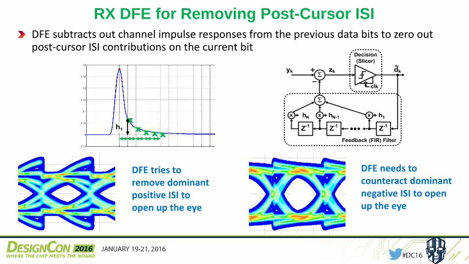
DFE subtracts out channel impulse responses from the previous data bits to zero out post-cursor ISI contributions on the current bit
xxx xx
RX DFE for Removing Post-Cursor ISI
DFE tries to remove dominant positive ISI to open up the eye
DFE needs to counteract dominant negative ISI to open up the eye
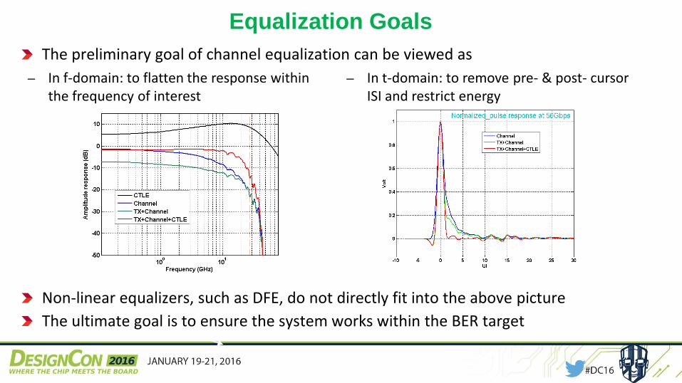
Equalization Goals
The preliminary goal of channel equalization can be viewed as
Non-linear equalizers, such as DFE, do not directly fit into the above picture
The ultimate goal is to ensure the system works within the BER target
‒ In f-domain: to flatten the response within the frequency of interest
‒ In t-domain: to remove pre- & post- cursor ISI and restrict energy
COM Analysis Example
of a TwinAx Cable
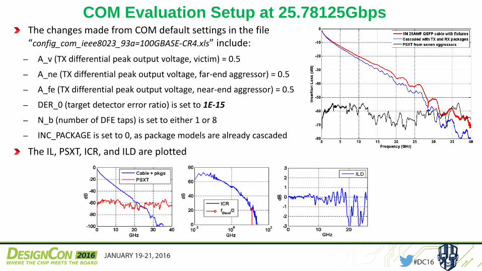
COM Evaluation Setup at 25.78125GbpsThe changes made from COM default settings in the file “config_com_ieee8023_93a=100GBASE-CR4.xls” include:
‒ A_v (TX differential peak output voltage, victim) = 0.5
‒ A_ne (TX differential peak output voltage, far-end aggressor) = 0.5
‒ A_fe (TX differential peak output voltage, near-end aggressor) = 0.5
‒ DER_0 (target detector error ratio) is set to 1E-15
‒ N_b (number of DFE taps) is set to either 1 or 8
‒ INC_PACKAGE is set to 0, as package models are already cascaded
The IL, PSXT, ICR, and ILD are plotted
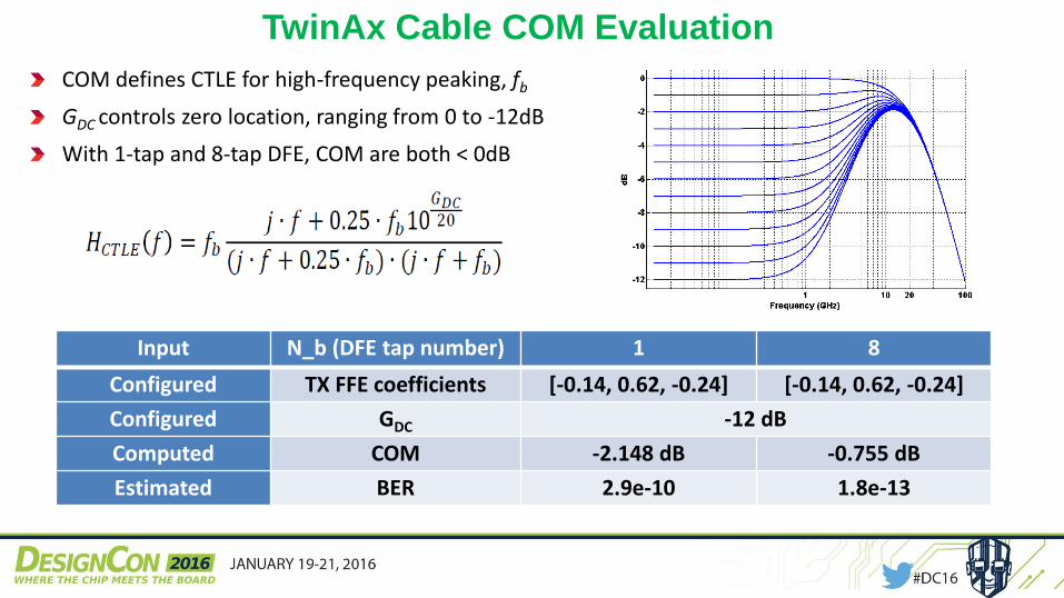
TwinAx Cable COM Evaluation
COM defines CTLE for high-frequency peaking, fb
GDC controls zero location, ranging from 0 to -12dB
With 1-tap and 8-tap DFE, COM are both < 0dB
Input N_b (DFE tap number) 1 8
Configured TX FFE coefficients [-0.14, 0.62, -0.24] [-0.14, 0.62, -0.24]
Configured GDC -12 dB
Computed COM -2.148 dB -0.755 dB
Estimated BER 2.9e-10 1.8e-13
CTLE Optimization for
Cable Channels
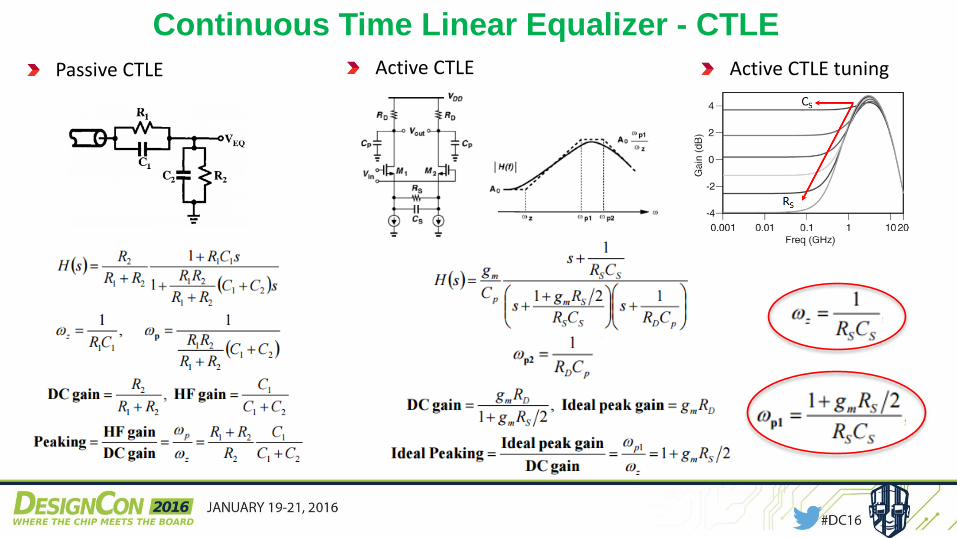
Continuous Time Linear Equalizer - CTLE
Passive CTLE Active CTLE Active CTLE tuning
The Role of Mid-Frequency CTLE
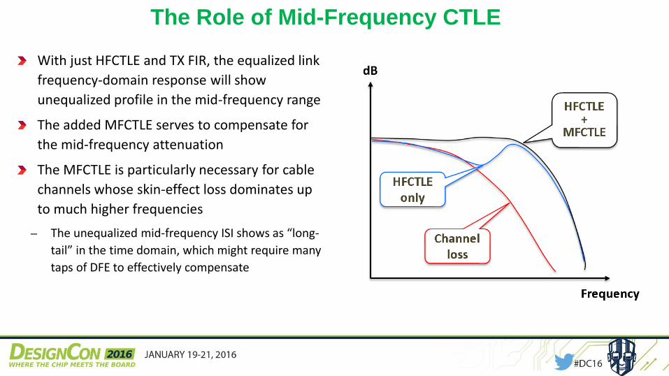
With just HFCTLE and TX FIR, the equalized link
frequency-domain response will show
unequalized profile in the mid-frequency range
The added MFCTLE serves to compensate for
the mid-frequency attenuation
The MFCTLE is particularly necessary for cable
channels whose skin-effect loss dominates up
to much higher frequencies
‒ The unequalized mid-frequency ISI shows as “long-
tail” in the time domain, which might require many
taps of DFE to effectively compensate
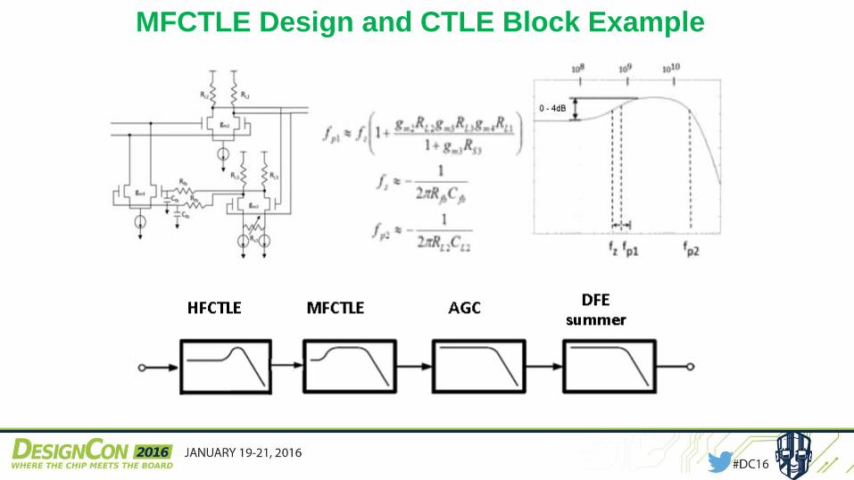
MFCTLE Design and CTLE Block Example
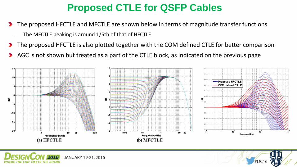
Proposed CTLE for QSFP Cables
The proposed HFCTLE and MFCTLE are shown below in terms of magnitude transfer functions
‒ The MFCTLE peaking is around 1/5th of that of HFCTLE
The proposed HFCTLE is also plotted together with the COM defined CTLE for better comparison
AGC is not shown but treated as a part of the CTLE block, as indicated on the previous page
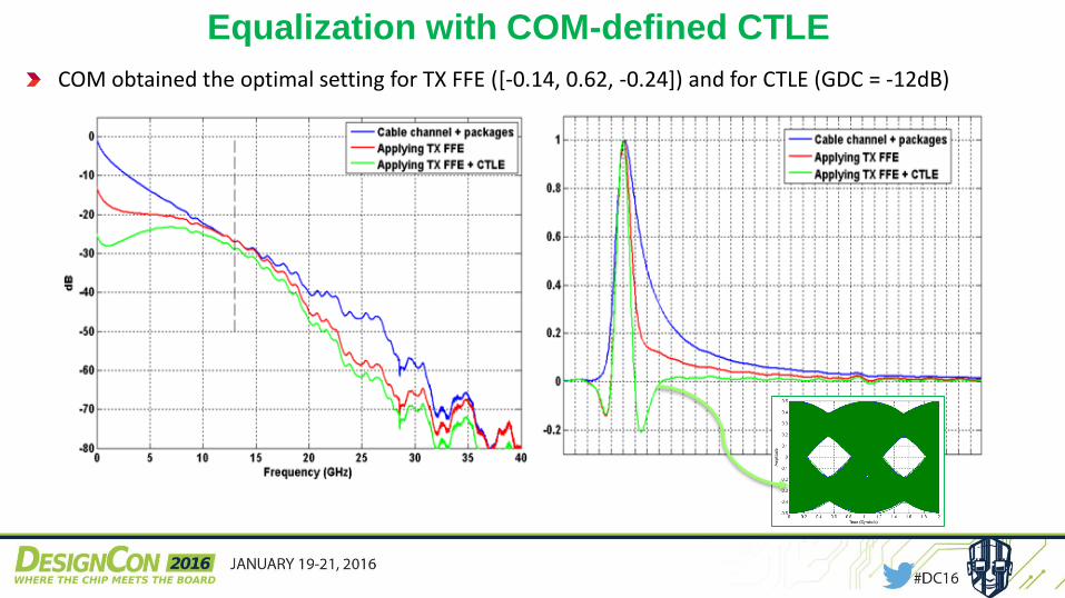
Equalization with COM-defined CTLE
COM obtained the optimal setting for TX FFE ([-0.14, 0.62, -0.24]) and for CTLE (GDC = -12dB)
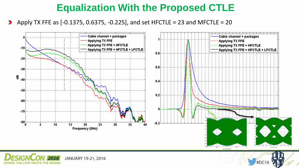
Equalization With the Proposed CTLE
Apply TX FFE as [-0.1375, 0.6375, -0.225], and set HFCTLE = 23 and MFCTLE = 20
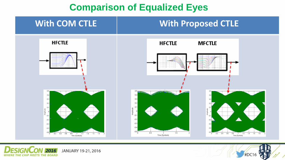
With COM CTLE With Proposed CTLE
Comparison of Equalized Eyes
Cable Link Time
Domain Simulations
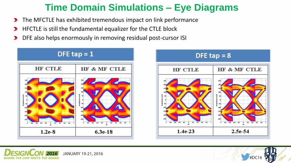
Time Domain Simulations – Eye DiagramsThe MFCTLE has exhibited tremendous impact on link performance
HFCTLE is still the fundamental equalizer for the CTLE block
DFE also helps enormously in removing residual post-cursor ISI
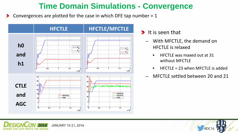
Time Domain Simulations - ConvergenceConvergences are plotted for the case in which DFE tap number = 1
It is seen that
‒ With MFCTLE, the demand on HFCTLE is relaxed
HFCTLE was maxed out at 31 without MFCTLE
HFCTLE = 23 when MFCTLE is added
‒ MFCTLE settled between 20 and 21
HFCTLE HFCTLE/MFCTLE
h0
and
h1
CTLE
and
AGC
Evaluation of a
100GBASE-CR4 System
100GBASE-CR4 Setup
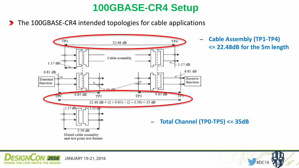
The 100GBASE-CR4 intended topologies for cable applications
‒ Cable Assembly (TP1-TP4) <= 22.48dB for the 5m length
‒ Total Channel (TP0-TP5) <= 35dB
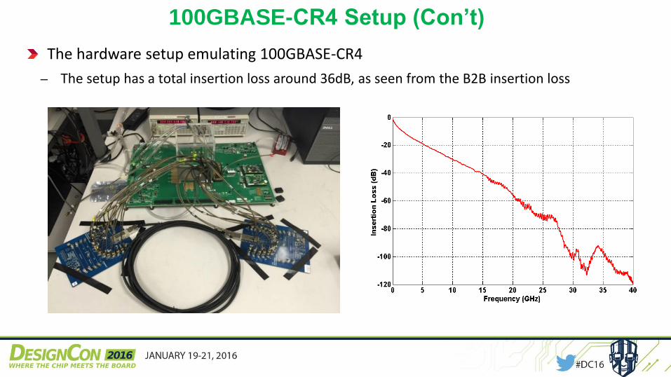
100GBASE-CR4 Setup (Con’t)
The hardware setup emulating 100GBASE-CR4
‒ The setup has a total insertion loss around 36dB, as seen from the B2B insertion loss
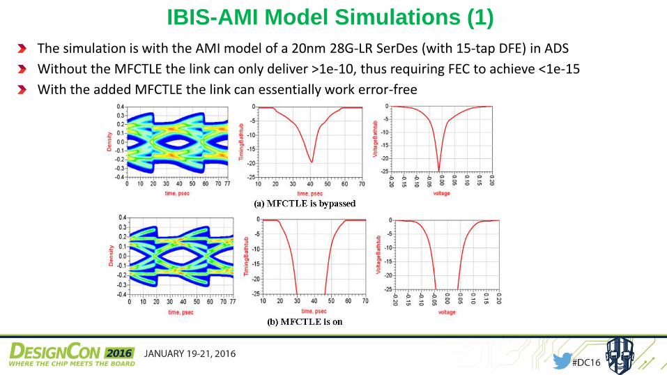
IBIS-AMI Model Simulations (1)
The simulation is with the AMI model of a 20nm 28G-LR SerDes (with 15-tap DFE) in ADS
Without the MFCTLE the link can only deliver >1e-10, thus requiring FEC to achieve <1e-15
With the added MFCTLE the link can essentially work error-free
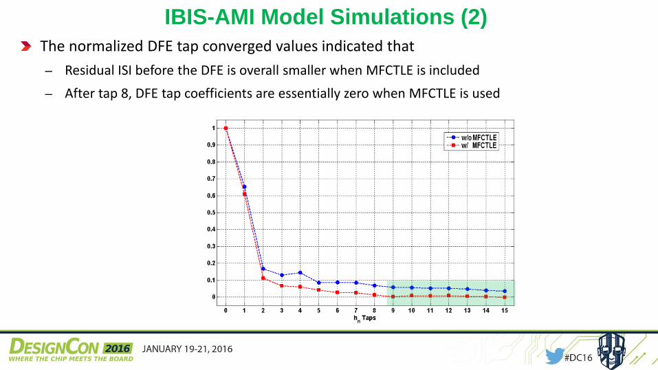
IBIS-AMI Model Simulations (2)
The normalized DFE tap converged values indicated that
‒ Residual ISI before the DFE is overall smaller when MFCTLE is included
‒ After tap 8, DFE tap coefficients are essentially zero when MFCTLE is used
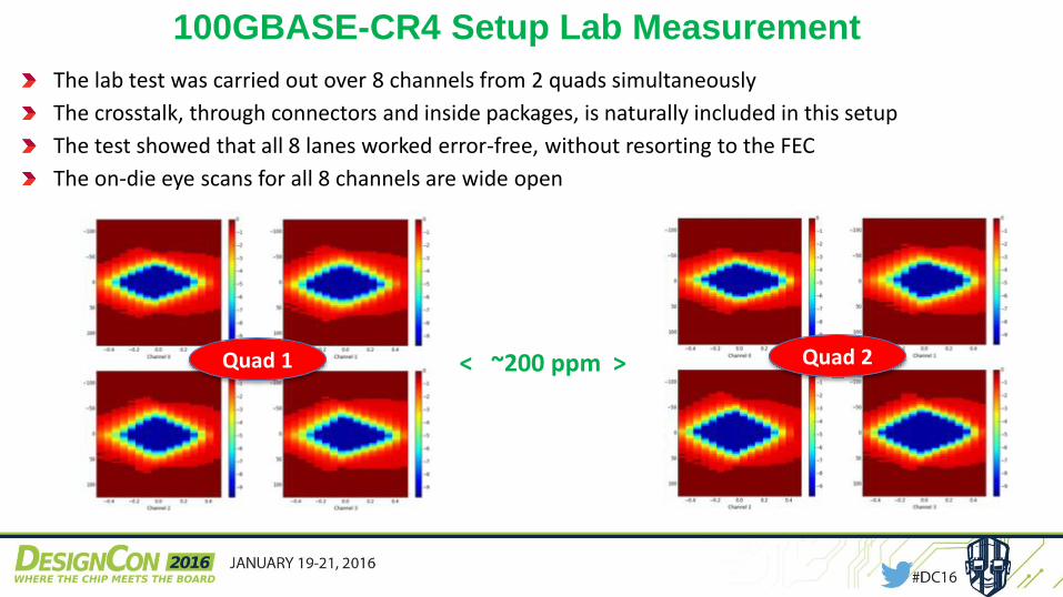
100GBASE-CR4 Setup Lab Measurement
The lab test was carried out over 8 channels from 2 quads simultaneously
The crosstalk, through connectors and inside packages, is naturally included in this setup
The test showed that all 8 lanes worked error-free, without resorting to the FEC
The on-die eye scans for all 8 channels are wide open
Quad 1 Quad 2< ~200 ppm >
Conclusions
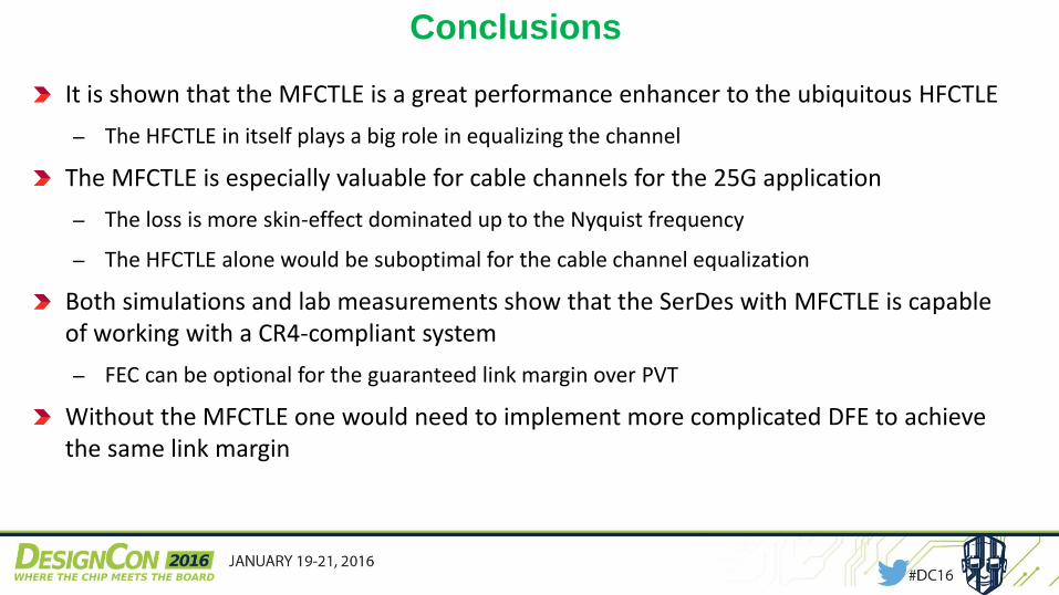
It is shown that the MFCTLE is a great performance enhancer to the ubiquitous HFCTLE
‒ The HFCTLE in itself plays a big role in equalizing the channel
The MFCTLE is especially valuable for cable channels for the 25G application
‒ The loss is more skin-effect dominated up to the Nyquist frequency
‒ The HFCTLE alone would be suboptimal for the cable channel equalization
Both simulations and lab measurements show that the SerDes with MFCTLE is capable of working with a CR4-compliant system
‒ FEC can be optional for the guaranteed link margin over PVT
Without the MFCTLE one would need to implement more complicated DFE to achieve the same link margin
Acknowledgment
The authors wish to thank Sai Lalith Chaitanya Ambatipudi for hardware setup and all the measurement data.
The authors also wish to thank Hongtao Zhang for the many insightful discussions.
References (1)
1. “High-speed Serial Interface”, High-Speed Circuits and Systems Lab, Yonsei University.
2. Samuel Palermo, “High-Speed Serial I/O Design for Channel Limited and Power-Constrained
Systems”, Texas A&M University
3. Matthew Brown, et al, “The state of IEEE 802.3bj 100 Gb/s Backplane Ethernet”, DesignCon
2014.
4. David M Pozar, “Microwave Engineering”, Third Edition, 2006.
5. Edward P Sayre, Jinhua Chen, Micheal A. Baxter, “OC-48/2.5Gbps interconnect engineering
design rules”, Design Con, 1999.
6. Vladimir Stojanović, “A systems approach to building modern high-speed links”, Integrated
Systems Group, MIT.
7. Megha Shanbhag, et al, “COMPLIANCE CHECK FOR UPLOADED TEC CHANNELS
Against IEEE802.3bj Draft1.2”, Nov. 2012, TE Connectivity.
8. Application Report, SLLA338–June 2013, “The Benefits of Using Linear Equalization in
Backplane and Cable Applications”, Texas Instruments.
References (2)
9. Richard Mellitz, “ Various Topics for Computing Channel Operating Margin (COM) – 100 Gb/s
Ethernet backplane and copper cable channel specification… A new signal integrity”, Intel,
Feb. 2014.
10. Richard Mellitz, et al, “Channel Operating Margin (COM): Evolution of Channel Specifications
for 25 Gbps and Beyond”, DesignCon 2013.
11. COM source code from “ran_com_3bj_3bm_01_1114.zip”.
12. Samir Parikh, et al, “A 32Gb/s Wireline Receiver with a low-frequency Equalizer, CTLE and 2-
Tap DFE in 28nm CMOS”, ISSCC 2013.
13. Jafar Savoj, et al, “Design of High-Speed Wireline Transceivers for Backplane
Communications in 28nm CMOS”, CICC, 2012 IEEE.
14. Yoshiyasu Doi et al, “Ultra-high-speed Interconnect Technology for Processor Communication”,
Fujitsu Sci. Tech., Vol. 50, No 1, January 2014.
15. Application Note, “100 Gb/s Ethernet 100GBASE-CR4 Test Points and Test Fixtures”, Keysight.
16. IEEE Std 802.3bj-2014, AMENDMENT TO IEEE Std 802.3-2012: Ethernet.
---
QUESTIONS?
Thank you!