Embed Size (px)
Citation preview
26/06/2003 Nigel Smale University of Oxford
IntroductionThe BeetleMA0 back-up solution. A readout chip that complies to the LHCb read out specifications and can interface directly to a Multi-anode pmt with a photon response of 300,000 electrons.
The BeetleMA0 was submitted on the 2nd of December 2002 and arrived in Oxford on 8th of April 2003.
1. Set up2. Analogue response to single photon3. Pipeline response to single photon4. News on Beetle1.3 submission 30th June.5. Is Beetle1.3MA1 submission needed6. Conclusion7. Future work
26/06/2003 Nigel Smale University of Oxford
Set up1. No common mode correction.2. Analogue test point is an access point to the buffer of a front
end of a Beetle1.2MA0 amplifier located at channel 1. This input is bonded and connected to a MApmt.
3. A pipe line measurement is when channel 1 (bullet point 2 above) is read out via the pipe line column number 35H through CLC400 receiver circuitry.
4. MAPmt has the serial number 9C23A4.5. Chip 42 from wafer D4KKGZKT is under test.6. In total 12 channels are bonded and connected to the MAPmt,
test channel (standard front end), ch0-2 (Attenuation amp), ch8-10 (standard front end) and ch115-119 (Attenuation amp).
7. Ipre=596,Isha=78,Ibuf=110,Ipipe=102,vd=1265,vdcl=1216, Ivoltbuf=204,Isf=204 and Icurrent=533, vfs=0,vfp=0.
26/06/2003 Nigel Smale University of Oxford
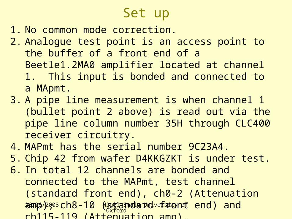
1x 1.2 T
Dummy Att
3x 1.2AttT
Ch(0..2)
3x 1.2DivT
Ch(3..5)
2x FBRmod
Ch(6..7)
3x 1.2_T
Ch(8..10)
53x 1.2Div
Ch(11..63)
64x1.2Att
Ch(64..127)
Beetle1.2_MA0 Floor PlanIocc input to ch4, Prebias, Prebias1, Shabias, Shabias1, Bufbias, Att_T, Div_t, FBRmod, 1.2_T
5.2mm
6.1mm
26/06/2003 Nigel Smale University of Oxford
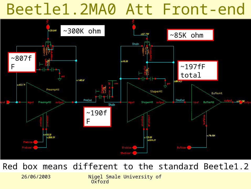
Beetle1.2MA0 Att Front-end~300K ohm
~807fF
~85K ohm
~197fF total
~190fF
Red box means different to the standard Beetle1.2
26/06/2003 Nigel Smale University of Oxford
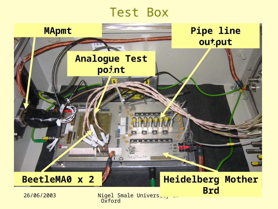
Test Box
MApmt Pipe line output
BeetleMA0 x 2 Heidelberg Mother Brd
Analogue Test point
26/06/2003 Nigel Smale University of Oxford
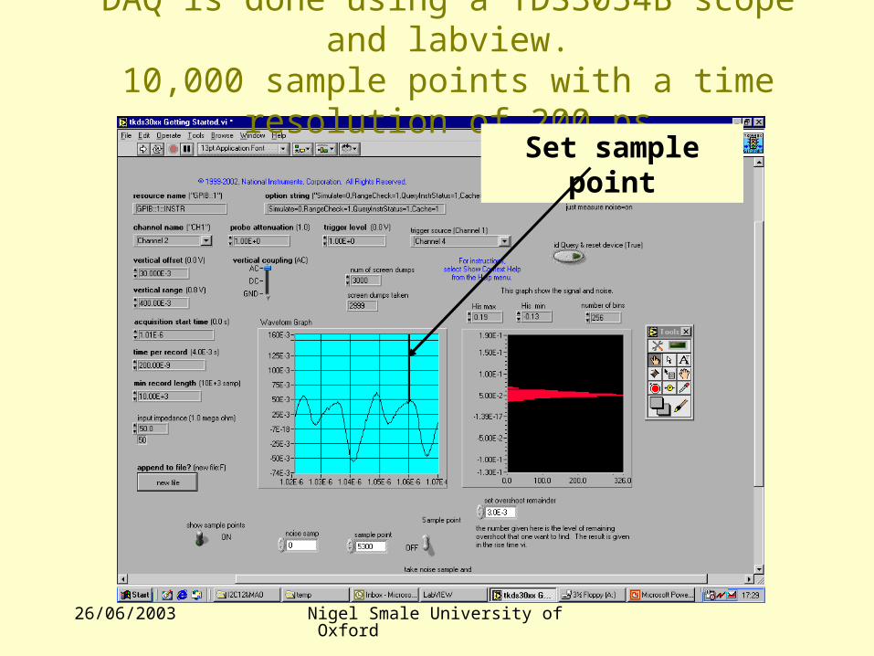
DAQ is done using a TDS3054B scope and labview.10,000 sample points with a time resolution of 200 ps
Set sample point
26/06/2003 Nigel Smale University of Oxford
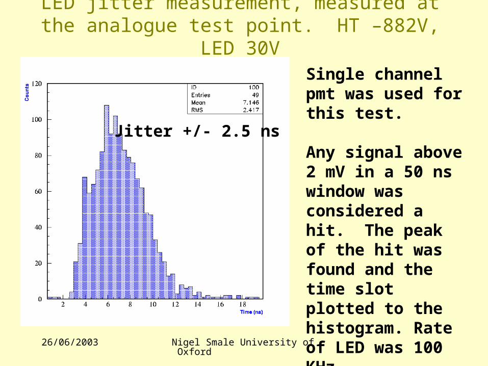
LED jitter measurement, measured at the analogue test point. HT –882V, LED 30V
Single channel pmt was used for this test.
Any signal above 2 mV in a 50 ns window was considered a hit. The peak of the hit was found and the time slot plotted to the histogram. Rate of LED was 100 KHz.Scope sample rate 5 GS/s.
Jitter +/- 2.5 ns
26/06/2003 Nigel Smale University of Oxford
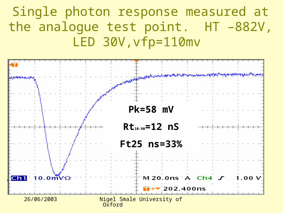
Single photon response measured at the analogue test point. HT –882V, LED 30V,vfp=110mv
Pk=58 mV
Rt10-90=12 nS
Ft25 ns=33%
26/06/2003 Nigel Smale University of Oxford
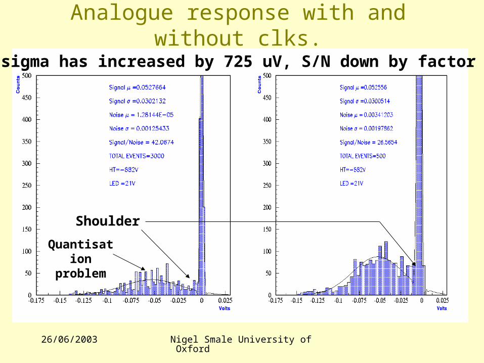
Analogue response with and without clks.
Shoulder
Noise sigma has increased by 725 uV, S/N down by factor of 1.5
Quantisation problem
26/06/2003 Nigel Smale University of Oxford
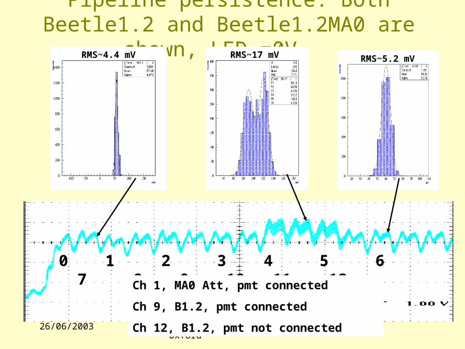
Pipeline persistence: Both Beetle1.2 and Beetle1.2MA0 are shown, LED =0V.
0 1 2 3 4 5 6 7 8 9 10 11 12
RMS~4.4 mV RMS~5.2 mVRMS~17 mV
Ch 1, MA0 Att, pmt connected
Ch 9, B1.2, pmt connected
Ch 12, B1.2, pmt not connected
26/06/2003 Nigel Smale University of Oxford
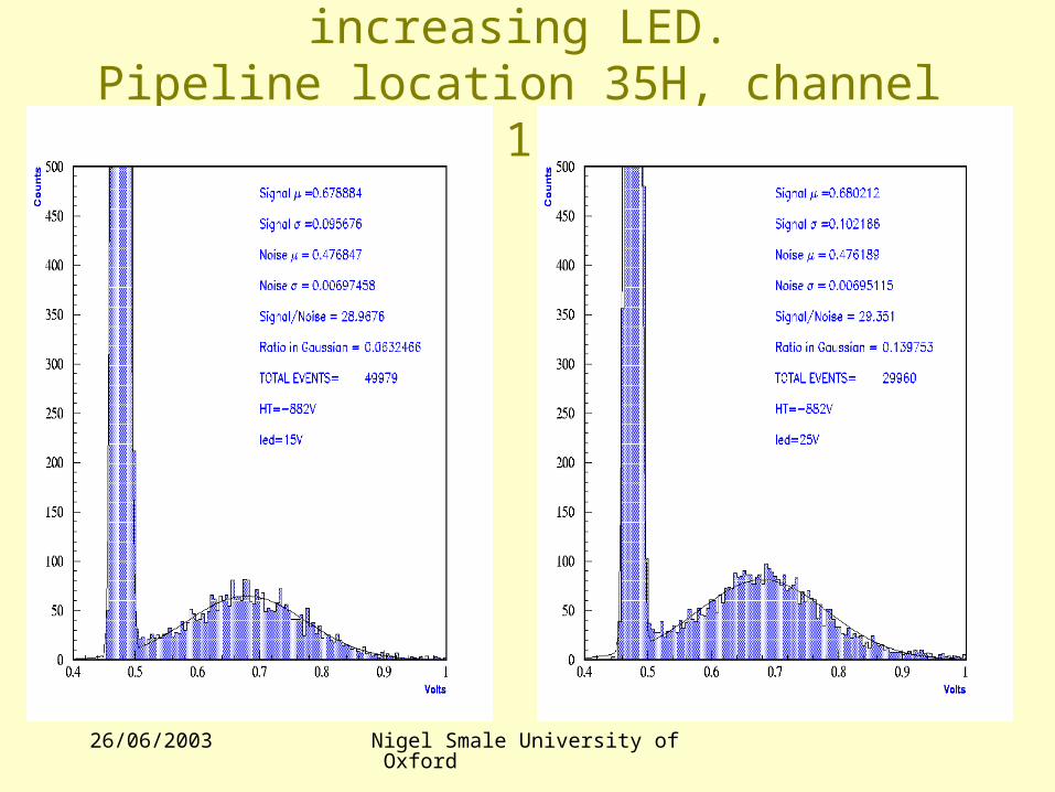
Pipeline response with increasing LED.Pipeline location 35H, channel 1
26/06/2003 Nigel Smale University of Oxford
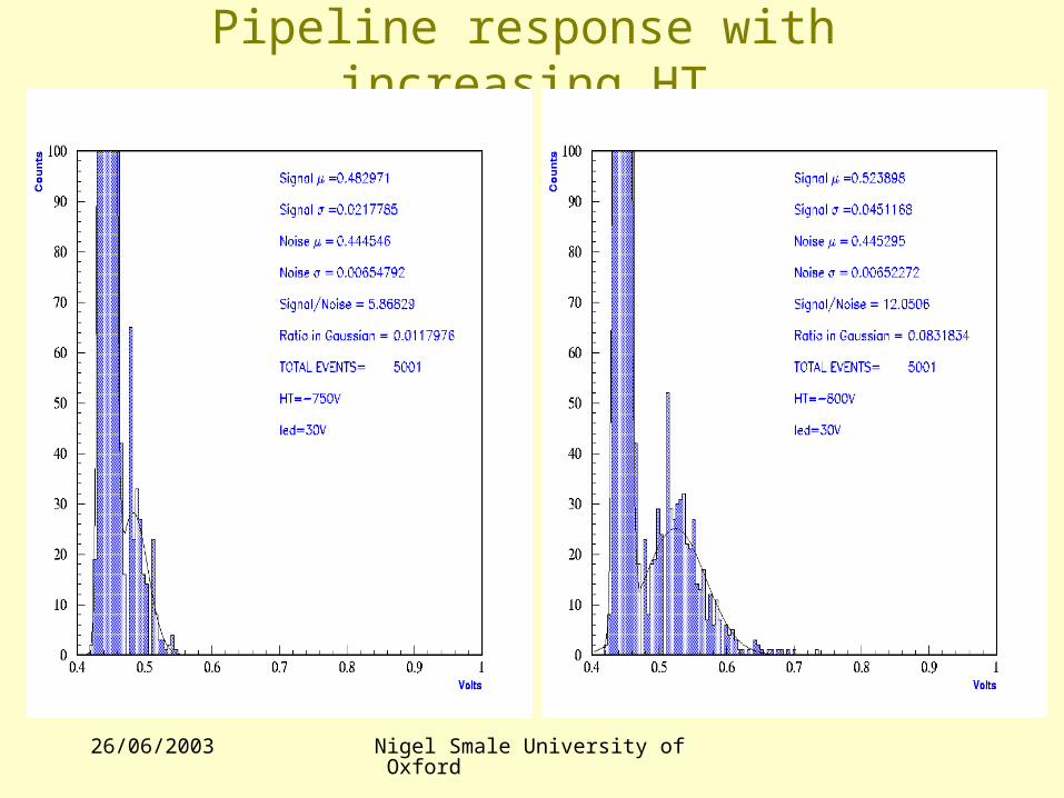
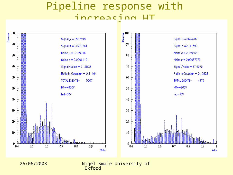
Pipeline response with increasing HT
26/06/2003 Nigel Smale University of Oxford
Pipeline response with increasing HT

26/06/2003 Nigel Smale University of Oxford
New on Beetle1.3 •Sticky charge effect. Fault has been simulated, die has been opened and probe inserted to emulate bug fix. Problem solved by adding analogue delay to the reset of pipe amp (might be track and hold). No change in digital control logic needed.
•Base-line variation. Fault has been simulated and die opened to measure Vdd of shaper to show voltage drop. External source has been supplied to show fix will work. Fix is by increasing x of chip by ~200um and increasing power rail.
•Comparator. No change of control logic, just change 3 bit shift reg to a 5 bit shift reg.
•Over-voltage problem. Current on output buffer killed chip, output is now restricted to 100uA, should be done by user.
•80MHz clk feed through, understood, to many fanouts. Fix is to change clk trunk and control layout.
•Next MPW submission is 30th June, Engineering run Q1 2004.

26/06/2003 Nigel Smale University of Oxford
Chip submission considerations
•Heidelberg engineering & production run has been paid for, this is considered to be MPI’s contribution to LHCb.
•If we take 1.3 chips or join the HD submission in Q1 2004 with MA chips the cost for the RICH group will probably be wavered.
•If we do not take 1.3 chips and go for a later MA engineering/production run then we will be liable for the full cost.
26/06/2003 Nigel Smale University of Oxford
Chip submission costing•Cost of an engineering run is about 20% more than a production run. Can share these costs with other groups.
•Sharing production runs is not easy. Timing is difficult, can be restrictions on die sizes because of dicing, have to also share the engineering run as engineering mask must go to production.
•Around 800 chips/wafer for a BeetleMAP size chip. LHCb RICH needs around 2000 chips (assuming an 80% yield and no spares) therefore 2.5 wafers.
•Engineering run gives 2-6 wafers, but only guarantees 2. So maybe possible to get all the chips from an engineering run. But if the target is not met then will have to pay out for a full production of 48 wafers, might be wise to consider sharing.
26/06/2003 Nigel Smale University of Oxford
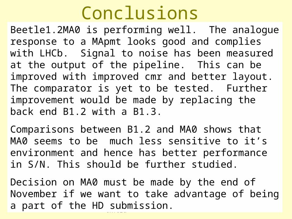
ConclusionsBeetle1.2MA0 is performing well. The analogue response to a MApmt looks good and complies with LHCb. Signal to noise has been measured at the output of the pipeline. This can be improved with improved cmr and better layout. The comparator is yet to be tested. Further improvement would be made by replacing the back end B1.2 with a B1.3.
Comparisons between B1.2 and MA0 shows that MA0 seems to be much less sensitive to it’s environment and hence has better performance in S/N. This should be further studied.
Decision on MA0 must be made by the end of November if we want to take advantage of being a part of the HD submission.
26/06/2003 Nigel Smale University of Oxford
1. Analogue pipeline offsets2. Noise measurements, increasing in c load3. Gain measurements, spread if any across channels4. Best parameters for running5. A/c response, I.e bandwidth6. Corner measurements I.e temp, max clk, jitter7. Threshold scans for comp out and pipeline out8. Cross talk, analogue and binary9. Time walk into adjacent pipeline cells10. Common mode power rejection, effects of varying Vsupply11. Supply voltage margin > 2.5V12. Dead time for large saturating input pulse13. DC drift over time14. And more
Future Work