Embed Size (px)
Citation preview

RECORD SERIAL NUMBER HEREManual P/N 26085-00Rev. 022411Companion to P/N 26086-00SN Range: B01395-D00000
OWNER’SMANUAL
AGCOCHALLENGER FHB SERIES
GLEANER SERIES 2, 3, 5, 7 & 9GLEANER/MASSEY FERGUSON 8200
MASSEY FERGUSON 9850

© 2011, Crary Industries, All rights reserved. Produced and printed in the USA.
HOW TO REACH US
ADDRESS HOURS TELEPHONEFAX NUMBER
E-MAILINTERNET
Crary Industries, Inc.237 12th St. NW
West Fargo, ND 58078
Monday-Friday 8 am-5pm (CST)
For Parts and Service:Ph: 701.282.5520 •
800.247.7335Fax: 701.282.9522
Email: [email protected] • [email protected]
Online: www.crary.com
Serial Number Decal
MANIFOLD, CWS
DECAL, CWS LOGO
DECAL,SERIAL NUMBER
Serial number location
DISCLAIMERThis document is based on information available at the time of its publication. While efforts have been made to be accurate, the information contained herein does not purport to cover all details or variations, nor to provide for every possible contingency in con-nection with installation, operation, or maintenance. Features may be described herein which are not present in all systems. Crary Industries assumes no obligation of notice to holders of this document with respect to changes subsequently made.
Crary Industries assumes no responsibility for the accuracy, completeness, sufficiency, or usefulness of the information contained herein.
SPECIFICATIONS AND DESIGN ARE SUBJECT TO CHANGE WITHOUT NOTICE.Crary Industries is continually making improvements and developing new equipment. In doing so, we reserve the right to make changes or add improvements to our product without obligation for equipment previously sold.
Because modification to this machine may affect the performance, function, and safety of its operation, no modifications are to be made without the written permission of Crary Industries. Part replacements should be with original equipment supplied by Crary Industries.
THE CRARY INDUSTRIES STATEMENT OF PRODUCT SAFETYAs a manufacturer of specialized agricultural equipment, Crary Industries fully recognizes its responsibility of providing its customers products that perform their expected use in a reasonably safe manner. Safety considerations shall be an integral and high prior-ity part of all engineering/design analysis and judgments involving Crary products. It is our stated policy that our products will be manufactured to comply with the safety standards specified by the American Society of Agricultural Engineers, the National Electrical Code, the Society of Automotive Engineers, and/or any other applicable recognized standards at the time manufactured. However, this statement should not be construed to mean that our product will safeguard against a customer’s own carelessness or neglect in violating common safety practices specified in each product’s manual, nor will we be liable for any such act.
SERIAL NUMBER LOCATIONAlways give your authorized Crary dealer the serial number of your machine when ordering parts, requesting service, or any other information. The serial number decal is located on the front, left hand end of the air manifold, as shown below.
Please record the serial number in the space provided on the front cover and on the warranty and registration card.
MANUFACTURED BY CRARY INDUSTRIES
MANUFACTURED IN U.S.A.XXXXXX
WEST FARGO, NORTH DAKOTA 58078 U.S.A.SERIAL NUMBER

LIMITED WARRANTY
This warranty applies to all AG and Outdoor Power Equipment manufactured by Crary Industries.
Crary Industries warrants to the original owner each new Crary Industries product to be free from defects in material and workmanship, under normal use and service. The warranty shall extend 1 year from date of delivery for income producing (commercial) applications and 2 years from date of delivery for non-income producing (consumer) use of the product. The product is warranted to the original owner as evidenced by a completed warranty registration on fi le at Crary Industries. Replacement parts are warranted for (90) days from date of installation.
ALL FINGER AIR REEL AND CWS SYSTEMS MANUFACTURED WITH A SERIAL NUMBER BEGINNING WITH THE LETTER “B” AND LATER WILL HAVE A LIMITED 2 SEASON WARRANTY ON THE COMPETE SYSTEM.
The warranty registration must be completed and returned to Crary Industries within 10 days of delivery of the product to the original owner or the warranty will be void.
In the event of a failure, return the product, at your cost, along with proof of purchase to the selling Crary In-dustries dealer. Crary Industries will, at its option, repair or replace any parts found to be defective in material or workmanship. Warranty on any repairs will not extend beyond the product warranty. Repair or attempted repair by anyone other than a Crary Industries dealer as well as subsequent failure or damage that may occur as a result of that work will not be paid under this warranty. Crary Industries does not warrant replacement components not manufactured or sold by Crary Industries.1. This warranty applies only to parts or components that are defective in material or workmanship.
2. This warranty does not cover normal wear items including but not limited to bearings, belts, pulleys, filters and chipper knives.
3. This warranty does not cover normal maintenance, service or adjustments.
4. This warranty does not cover depreciation or damage due to misuse, negligence, accident or improper maintenance.
5. This warranty does not cover damage due to improper setup, installation or adjustment.
6. This warranty does not cover damage due to unauthorized modifications of the product.
7. Engines are warranted by the respective engine manufacturer and are not covered by this warranty.
Crary Industries is not liable for any property damage, personal injury or death resulting from the unauthor-ized modifi cation or alteration of a Crary product or from the owner’s failure to assemble, install, maintain or operate the product in accordance with the provisions of the Owner’s manual.
Crary Industries is not liable for indirect, incidental or consequential damages or injuries including but not limited to loss of crops, loss of profi ts, rental of substitute equipment or other commercial loss.
This warranty gives you specifi c legal rights. You may have other rights that may vary from area to area.
Crary Industries makes no warranties, representations or promises, expressed or implied as to the perfor-mance of its products other than those set forth in this warranty. Neither the dealer nor any other person has any authority to make any representations, warranties or promises on behalf of Crary Industries or to modify the terms or limitations of this warranty in any way. Crary Industries, at its discretion, may periodically offer limited, written enhancements to this warranty.
CRARY INDUSTRIES RESERVES THE RIGHT TO CHANGE THE DESIGN AND/OR SPECIFICATIONS OF ITS PRODUCTS AT ANY TIME WITHOUT OBLIGATION TO PREVIOUS PURCHASERS OF ITS PRODUCTS.
NOTEThe warranty will not cover gearboxes that have been disas-sembled within the warranty period.

iv PN 26085-00 R022411
GEARBOX MOUNT DRIVE KIT
KIT NUMBER NUMBER OF BOXES IN KIT
22676 1
DRIVELINE KIT
KIT NUMBER NUMBER OF BOXES IN KIT
27699-00 1
27701-00 1
29770-00 1
REEL ARM MOUNT KIT
KIT NUMBER NUMBER OF BOXES IN KIT
25994 2
DROP TUBE KIT
KIT NUMBER NUMBER OF BOXES IN KIT
25919 1
25920 1
INSPECTION AFTER DELIVERYAfter receiving the shipment of your CWS, please ensure that no boxes are missing. The following tables show the number of boxes included in all kits available for a AGCO CWS. Refer to your packing slip to see which kits you should have received. Then, ensure that all boxes were shipped. Contact your dealer immediately if any boxes are missing.
MANIFOLD KIT
KIT NUMBER NUMBER OF BOXES IN KIT
25926 1
25942 1
53254 1
53247 1
53242 1
53237 1
53232 1
53220 1
53217 1
27500 1
27502 1
27247 1
RIGHT HAND DRIVE KIT
KIT NUMBER NUMBER OF BOXES IN KIT
24060 1
24061 1
24062 3
24106 3
29773 3
29984 2

v PN 26085-00 R022411
TABLE OF CONTENTS
DESCRIPTION PAGE DESCRIPTION PAGE
INTRODUCTION .................................................... 2
SAFETY ................................................................. 32.1 SAFETY ALERT SYMBOL ................................................................... 32.2 GENERAL SAFETY.............................................................................. 42.3 OPERATING SAFETY .......................................................................... 52.4 MAINTENANCE SAFETY .................................................................... 52.5 HYDRAULIC SAFETY .......................................................................... 62.6 PTO SAFETY ....................................................................................... 62.7 TRANSPORT SAFETY ......................................................................... 72.8 STORAGE SAFETY ............................................................................. 72.9 ASSEMBLY SAFETY ............................................................................ 72.10 SAFETY DECALS .............................................................................. 72.11 SIGN-OFF FORM ............................................................................... 8
SAFETY DECALS .................................................. 9
ASSEMBLY .......................................................... 104.1 DRIVELINE ADJUSTMENT ................................................................ 10
4.1.1 SHORTENING THE DRIVELINE (OPTION A) ........................ 104.1.2 SHORTENING THE DRIVELINE (OPTION B) ........................ 10
4.2 GEARBOX/FAN MOUNT .....................................................................114.3 RIGHT HAND DRIVE KIT (18-22 FT. HEADERS) .............................. 124.4 RIGHT HAND DRIVE KIT (25-35 FT. HEADERS) .............................. 144.5 REEL ARM MOUNT ........................................................................... 16
4.5.1 LEFT HAND ............................................................................. 164.5.2 RIGHT HAND ........................................................................... 17
4.6 MANIFOLD ......................................................................................... 184.7 DROP TUBES .................................................................................... 19
4.7.1 MANIFOLDS WITH 12” TUBE SPACING ................................ 194.7.2 MANIFOLDS WITH 13-5/16” TUBE SPACING ........................ 19
4.8 FAN HOSE ASSEMBLY ..................................................................... 204.9 ELECTRICAL WIRING ....................................................................... 214.10 ELECTRIC ACTUATOR ................................................................... 224.11 OPTIONS .......................................................................................... 23
4.11.1 GEARBOX/FAN EXTENSION ................................................ 23
OPERATION ........................................................ 255.1 MACHINE COMPONENTS ................................................................ 265.2 INITIAL ADJUSTMENTS .................................................................... 27
5.2.1 MANIFOLD ADJUSTMENT ..................................................... 275.2.2 TORQUE LIMITER (SLIP CLUTCH) ........................................ 27
5.3 PRE-OPERATION CHECKLIST ......................................................... 285.4 MACHINE BREAK-IN ......................................................................... 28
5.4.1 PRE-START INSPECTION ...................................................... 285.4.2 AFTER OPERATING FOR 2 HOURS ...................................... 285.4.3 AFTER OPERATING FOR 10 HOURS: ................................... 28
5.5 CONTROLS........................................................................................ 295.5 CONTROLS........................................................................................ 295.6 OPERATING HINTS ........................................................................... 305.7 TRANSPORTING ............................................................................... 305.8 STORAGE .......................................................................................... 31
SERVICE & MAINTENANCE ............................... 326.1 MAINTENANCE CHECKLIST ............................................................ 326.2 FLUIDS AND LUBRICANTS............................................................... 336.3 GREASING......................................................................................... 336.4 GEARBOX OIL ................................................................................... 336.5 PTO LUBRICATION ........................................................................... 346.6 FAN HOUSING AND AIR HOSE ........................................................ 346.7 TORQUE LIMITER (SLIP CLUTCH) .................................................. 34
TROUBLESHOOTING ......................................... 357.1 GENERAL TROUBLESHOOTING ..................................................... 35
SPECIFICATIONS ................................................ 378.1 FAN PERFORMANCE DATA .............................................................. 378.2 BOLT TORQUE .................................................................................. 38

2 PN 26085-00 R022411
Congratulations on your choice of a new Crary Wind System (CWS) to complement your farming operation. This equip-ment has been designed and manufactured to meet the needs of a discerning Agricultural industry for the effi cient harvesting of crops.
Safe, effi cient, and trouble free operation of your CWS requires that you and anyone else who will be operating or maintaining the machine read and understand the Safety, Operation, Maintenance, and Troubleshooting information contained within this manual. Check each item referred to and acquaint yourself with the adjustments required to obtain safe, effi cient operation.
This manual covers all models of the CWS manufactured by Crary Company for AGCO headers. Differences are covered and explained where appropriate. Use the Table of Contents as a guide to locate required information.
Keep this manual handy for frequent reference and to pass on to new operators or owners. Call your Crary dealer or distributor if you need assistance, information, or additional copies of the manual.
Many people have worked on the design, production, and delivery of this machine. They have built into it the highest quality of materials and workmanship. The information in this manual is based on the knowledge, study, and experience of these people through years of manufacturing specialized farming machinery.
The performance of the machine depends on proper maintenance and adjustment. Even if you are an experienced opera-tor of this or similar equipment, we ask you to read this manual before operating the machine. Keep the manual handy for future reference. It has been carefully prepared, organized, and illustrated to assist you in fi nding the information you need. Your Crary dealer will be happy to answer any further questions you may have about the machine.
OPERATOR ORIENTATION - All references to left, right, front and rear of the machine, as mentioned throughout the manual, are determined by standing behind the machine and facing the direction of forward travel.
Section INTRODUCTION1
3 PN 26085-00 R022411
SAFETYSection2
2.1 SAFETY ALERT SYMBOL
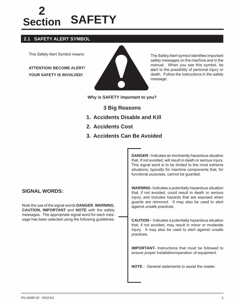
DANGER - Indicates an imminently hazardous situation that, if not avoided, will result in death or serious injury. This signal word is to be limited to the most extreme situations, typically for ma chine components that, for functional purposes, cannot be guarded.
WARNING- Indicates a potentially hazardous situation that, if not avoided, could result in death or serious injury, and includes hazards that are exposed when guards are removed. It may also be used to alert against unsafe prac tices.
CAUTION - Indicates a potentially hazardous situation that, if not avoided, may result in minor or moderate injury. It may also be used to alert against unsafe practices.
IMPORTANT- Instructions that must be followed to ensure proper installation/operation of equipment.
NOTE - General statements to assist the reader.
This Safety Alert Symbol means:
ATTENTION! BECOME ALERT!
YOUR SAFETY IS INVOLVED!
The Safety Alert symbol identifi es important safety messages on the machine and in the manual. When you see this symbol, be alert to the possibility of personal injury or death. Follow the instructions in the safety message.
Why is SAFETY important to you?
1. Accidents Disable and Kill2. Accidents Cost3. Accidents Can Be Avoided
SIGNAL WORDS:
Note the use of the signal words DANGER, WARNING, CAUTION, IMPORTANT and NOTE with the safety messages. The appropriate signal word for each mes-sage has been selected using the following guidelines:
3 Big Reasons

4 PN 26085-00 R022411
SAFETY
YOU are responsible for the SAFE operation and mainte-nance of your machine. You must ensure that you and any-one else who is going to operate, maintain or work around the machine are familiar with the operat ing and maintenance procedures and related safety information contained in this manual. This manual will alert you to all good safety prac-tices that should be adhered to while operat ing the machine.
Remember, YOU are the key to safety. Good safety prac-tices not only protect you but also the people around you. Make these practices a working part of your safety program. Be certain that EVERYONE operating this equipment is familiar with the recommended operating and maintenance procedures and follows all the safety precautions. Most accidents can be prevented. Do not risk injury or death by ignoring good safety practices.
• Owners must give operating instruc tions to opera-tors or employees before allowing them to operate the machine, and annually thereafter per OSHA (Occupational Safety and Health Administration) regulation 1928.57.
• The most important safety device on this equipment is a safe operator. It is the operator’s responsibility to read and under stand all Safety and Operating instructions in the manual and to follow them.
• A person who has not read and understood all operating and safety instructions is not qualified to operate the machine. An untrained operator exposes himself and bystanders to possible seri-ous injury or death.
• Do not modify the equipment in any way. Unauthor-ized modification may impair the function and/or safety and could affect the life of the equipment.
Think SAFETY! Work SAFELY!
2.2 GENERAL SAFETY
1. Read and understand the Owner’s Manual and all safety decals before operat-ing, maintaining, adjusting or servicing the machine.
2. Only trained persons shall operate the machine. An untrained operator is not qualified to operate the machine.
3. Have a first-aid kit available for use, should the need arise, and know how to use it.
4. Provide a fire extinguisher for use in case of an accident. Store in a highly visible place.
5. Do not allow children, spectators or by-standers within hazard area of machine.
6. Wear appropriate protective gear. This list includes but is not limited to:
• A hard hat.
• Protective shoes with slip resistant soles.
• Protective goggles.
• Heavy gloves.
• Hearing protection.
• Respirator or filter mask.7. Wear suitable ear protection during
prolonged exposure to excessive noise.
8. Place all controls in neutral or off, lower header to the ground, stop combine engine, set parking brake, chock wheels, re-move ignition key and wait for all moving parts to stop, before servicing, adjusting, repairing or unplugging.
9. Review safety related items annually with all person-nel who will be operating or maintain ing the machine.

5 PN 26085-00 R022411
SAFETY
1. Follow ALL operating, maintenance, and safety informa-tion in this manual.
2. Support the machine with blocks or safety stands when working around it.
3. Follow good shop practices:
• Keep service area clean and dry.
• Be sure electrical outlets and tools are properly grounded.
• Use adequate light for the job at hand.
4. Use only tools, jacks and hoists of sufficient capacity for the job.
5. Place all controls in neutral or off, lower header to the ground, stop combine engine, set parking brake, chock wheels, remove ignition key and wait for all moving parts to stop before servicing, adjusting, repairing or unplugging.
6. When maintenance work is completed, install and se-cure all guards before resuming work.
7. Relieve pressure from hydraulic circuit before servicing or disconnecting from combine.
8. Keep hands, feet, hair and clothing away from all mov-ing and/or rotating parts.
9. Clear the area of bystanders, especially small children, when carrying out any maintenance and repairs or mak-ing any adjustments.
10. Keep safety decals clean. Replace any decal that is damaged or not clearly visible.
11. First-class maintenance is a prerequisite for the safest operation of your machine. Maintenance, including lubrications, should be performed with the machine stopped and locked out.
1. Read and understand the owner’s manual and all safety decals before servicing, adjusting or repairing.
2. Install and secure all guards and shields before starting or operating.
3. Keep hands, feet, hair and clothing away from all mov-ing and/or rotating parts.
4. Place all controls in neutral or off, lower header to the ground, stop combine engine, set parking brake, chock wheels, remove ignition key and wait for all moving parts to stop before servicing, adjusting, repairing or unplugging.
5. Clear the area of bystanders, especially small children, before starting.
6. Keep all hydraulic lines, fittings, and couplers tight and free of leaks before and during use.
7. Clean reflectors and lights before transporting.
8. Review safety related items annually with all personnel who will be operating or maintaining the CWS.
9. Shut the combine off when connecting the machine hydraulics.
10. Do not exceed fan speed of 5300 RPM. Check the fan speed by multiplying the drive shaft speed (RPM) by the gear ratio of the gearbox.
11. Do not run the fan without back pressure. Close the butterfly valve on the fan if the flex hose is disconnected.
Think SAFETY! Work SAFELY!
2.3 OPERATING SAFETY 2.4 MAINTENANCE SAFETY

6 PN 26085-00 R022411
SAFETY
1. Always place all combine hydraulic controls in neutral before disconnecting from combine or working on hy-draulic system.
2. Make sure that all components in the hydraulic system are kept in good condition and are clean.
3. Relieve pressure before working on the hydraulic system.
4. Replace any worn, cut, abraded, flattened or crimped hoses.
5. Do not attempt any makeshift repairs to the hydraulic fittings or hoses by using tape, clamps or cements. The hydraulic system operates under extremely high-pressure. Such repairs will fail suddenly and create a hazardous and unsafe condition.
6. Wear proper hand and eye pro-tection when searching for a high-pressure hydraulic leak. Use a piece of wood or cardboard as a backstop instead of hands to isolate and identify a leak.
7. If injured by a concentrated high-pressure stream of hydraulic fluid, seek medical attention immedi-ately. Serious infection or toxic re-action can develop from hydraulic fluid piercing the skin surface.
8. Before applying pressure to the system, make sure all components are tight and that lines, hoses, and cou-plings are not damaged.
2.5 HYDRAULIC SAFETY 2.6 PTO SAFETY
Think SAFETY! Work SAFELY!
1. Keep bystanders, especially children, away from drive shafts.
2. Be extremely careful when working around PTO shafts, drivelines, or other rotating shafts.
3. Do not remove or modify protective shields or guards.
4. Do not step across a PTO shaft or driveline or use it as a step.
5. Keep guards and shields in place at all times while operating.
6. Replace all damaged or missing parts or shields with the correct original manufacturer’s parts.
7. Grease, clean, and maintain PTO components ac-cording to original manufacturer’s specifications and information in this manual.
8. Clothing worn by the operator must be fairly tight. Never wear loose-fitted jackets, shirts, or pants when working around the drive shafts. Tie long hair back or put under a cap.
9. Keep hydraulic hoses, electrical cords, chains, and other items from contacting the drive shafts.
10. Do not clean, lubricate, or adjust the drive shafts when the reel is engaged and the combine is running.

7 PN 26085-00 R022411
SAFETY
1. Make sure you are in compliance with all local regula-tions regarding transporting equipment on public roads and highways.
2. It is the responsibility of the owner to know the lighting and marking requirements of the local highway authori-ties and to install and maintain the equipment to provide compliance with the regulations. Add extra lights when transporting at night or during periods of limited visibility.
3. See the owner’s manual that came with your combine and header for proper transportation.
1. Keep safety decals clean and legible at all times.
2. Replace safety decals that are missing or have become illegible.
3. Replaced parts that displayed a safety decal should also display the current decal.
4. Decals that need to be replaced are to be placed back in the original location.
5. Safety decals are available from your authorized dealer or the factory.
HOW TO INSTALL SAFETY DECALS:1. Be sure that the installation area is clean and dry.
2. Be sure temperature is above 50°F (10°C).
3. Decide on the exact position before you remove the backing paper.
4. Remove the smaller portion of the split backing paper.
5. Align the decal over the specified area and carefully press the small portion with the exposed sticky back-ing in place.
6. Slowly peel back the remaining paper and carefully smooth the remaining portion of the decal in place.
7. Small air pockets can be pierced with a pin and smoothed out using the piece of decal backing paper.
2.7 TRANSPORT SAFETY 2.10 SAFETY DECALS
2.8 STORAGE SAFETY
2.9 ASSEMBLY SAFETY
1. Store the unit in an area away from human activity.
2. Do not permit children to play on or around the stored machine.
3. See the owner’s manual that came with your combine and header for proper storage.
1. Assemble in an area with sufficient space to handle the largest component and access to all sides of the machine
2. Use only lifts, cranes and tools with sufficient capacity for the load.
3. When necessary, have someone assist you.
4. Do not allow spectators in the working area.
5. Be sure to read the Maintenance Safety section.
THINK SAFETY! WORK SAFELY!

8 PN 26085-00 R022411
SAFETY
Crary Industries follows the general safety standards specifi ed by the American Society of Agricultural Engineers (ASAE) and the Occupational Safety and Health Administration (OSHA). Anyone who will be operating and/or maintaining the equipment must read and clearly understand ALL safety, operating and maintenance information presented in this manual.
Do not operate or allow anyone else to operate this equipment until such information has been reviewed. Annually review this information before the season start-up.
Make these periodic reviews of safety and operation a standard practice for all of your equipment. An untrained operator is unqualifi ed to operate this machine.
A sign-off sheet is provided for your record keeping to show that all personnel who will be working with the equipment have read and understood the information in the owner’s manual and have been instructed in the operation of the equipment.
SIGN - OFF FORM
2.11 SIGN-OFF FORM
DATE EMPLOYEE SIGNATURE EMPLOYER SIGNATURE

9 PN 26085-00 R022411
Good safety requires that you familiarize yourself with the various safety decals, the type of warning and the area, or particular function related to that area, that requires your SAFETY AWARENESS.
Think SAFETY! Work SAFELY!
REMEMBER - If safety decals have been damaged, removed or become illegible or parts have been replaced without safety decals, new decals must be applied. New safety decals are available from the manufacturer or an authorized dealer.
SAFETY DECALSSection3
PN 0732-0598-00 - Decal, Warning
PN 17423 - Decal, Danger

10 PN 26085-00 R022411
Section ASSEMBLY4
4.1.1 SHORTENING THE DRIVELINE (OPTION A)1. Pull the driveline into two pieces. Connect one end to
the combine and the other end to the drive shaft. Line up the two halves parallel to each other.
2. Measure the distance from the end of one driveline tube to the bottom of the end shield of the other driveline half (dimension A in Figure 1). Measure and mark the driveline tube 1-9/16” inward from dimension A.
3. Cut the shield tube in the marked position.
4. Using the cut piece of shield tube as your measurement, place the cut piece against the end of the shaft. Mark and cut the shaft.
5. Using the cut piece of shield tube as your measurement, mark and cut the tube on the other half of the driveline, and then the shaft.
6. File both shaft ends, and slide the two halves back together.
4.1 DRIVELINE ADJUSTMENT
IMPORTANTThe driveline shields must be reinstalled to the original equipment standards of construction and installation.
Figure 1: Shorten the driveline if it is too long
Figure 2: Removing the shield tube
4.1.2 SHORTENING THE DRIVELINE (OPTION B)1. Using a Phillips screwdriver, remove the screw at the
flexible cone base of the outer shield tube. Then, twist the flexible cone until the cone flare aligns with the bearing tab (Figure 2). Pull the yoke and inner profile out of the tubing.
2. Remove the spring pin.
3. Find a pipe that is large enough to slide the inner profile inside, but is small enough that the end yoke will not pass through. This pipe should extend at least 4 inches past the end of the driveline inner profile.
A. Insert the inner profile into the pipe.
B. Place a steel plate on the floor and, with the yoke pointing up, bounce the pipe on the steel plate. After several bounces, the inner profile should drop out of the yoke and onto the floor.
4. Cut the yoke end of both the shaft and shield tube by the length determined.
5. Insert the profile back into the yoke and drill a new spring pin hole.
6. Insert the spring pin.
7. Drill new holes in the shield to accept the shield bearing.
8. Install the driveline shield by reversing the disassembly process from Step 1.
If you determined that your driveline needs to be shortened, use the following steps to modify the shaft length.
If the amount required to be cut off does not include a grease zerk use the steps in section 4.2.1. If a grease zerk is within the cutting area, use the steps in section 4.2.2.

11 PN 26085-00 R022411
ASSEMBLY
4.2 GEARBOX/FAN MOUNT
Place all controls in neutral or off, stop combine engine, set parking brake, remove ignition key, wait for all mov-ing parts to stop, then properly block machine before servicing, adjusting, repairing, or unplugging.
WARNING
GEARBOX MOUNT PLATE
1/2” x 1-1/4” SERRATED FLANGE BOLT
MOUNT PLATE SUPPORT
1/2” x 1-1/4” SERRATED FLANGE BOLT
Figure 3: Gearbox mount kit
1. Position the mount plate support on the rear right hand side of the header as shown in Figure 4. Refer to Table 1 for Dimension “A.”
2. Using the mount plate support as a template, drill 17/32” holes through the top holes and 27/64” holes through the bottom mount plate support holes and into the rear header panel. Tap the bottom holes for 1/2” bolts.
3. Install the mount plate support to the header with four 1/2” x 1-1/4” serrated flange bolts (Figure 3). Secure the top bolts with washers and nuts. Torque hardware to 75 ft-lbs.
4. Attach the gearbox mount plates to the mount plate support with four 1/2” x 1-1/4” serrated flange bolts, washers and locknuts. Do not tighten yet.
5. Use a jack or hoist to position the gearbox inside the gearbox mount plates. Using four 1/2” x 1-1/4” serrated flange bolts, attach the gearbox to the top set of mount plate holes. Do not tighten yet.
6. Check the gearbox and, if necessary, fill the gearbox with lube before use.
Use Mobilube SHC 75W-90 synthetic gear lube or equivalent with the following specifications:
API Service GL-5/MT.1MIL-L-2105DMACK GO-J PLUSSAE J2360Capacity: 40 oz. (1.2 L)
HEADER WIDTH DIMENSION “A”15’ 23.50”16’ 23.50”18’ 29.50”20’ 23.50”22’ 29.50”
25’ (8200 & Challenger headers) 16.00”25’ (all other headers) 23.50”
30’ (8200 & Challenger headers) 25.50”30’ (all other headers) 29.50”
35’ 29.50”
Table 1, Measurements for Dimension “A”
Figure 4: Mount plate support
NOTEApply a medium strength thread locking agent to the bolts used to secure the gearbox mount to the header and the gearbox to the mount.

12 PN 26085-00 R022411
ASSEMBLY
4.3 RIGHT HAND DRIVE KIT (18-22 FT. HEADERS)
Place all controls in neutral or off, stop combine engine, set parking brake, remove ignition key, wait for all mov-ing parts to stop, then properly block machine before servicing, adjusting, repairing, or unplugging.
WARNING
Figure 5: Driveline support bracket
1. Install a bushing to each side of the gearbox (Figure 6). Make sure the bolts are inserted in the non-threaded bushing holes. The threaded set of holes is used to remove the bushing. Do not tighten the bolts yet.
2. Slide the provided drive shaft through the gearbox bush-ings. When doing so, install a 5/16” key in each bushing.
3. Position the drive shaft so that it protrudes approxi-mately 1-1/2” beyond the right hand gearbox bushing. Torque all six bushing bolts to 17 ft-lbs.
4. Attach a shield weldment to the right hand side of the gearbox with two 1/2” x 1” bolts and washers. Torque to 75 ft-lbs.
5. As needed, adjust the gearbox within the gearbox mount plates so that the drive shaft is parallel to the top of the header. Also, check both ends of the shaft for equal distance between the shaft and the back panel of the header.
6. Torque all gearbox mounting bolts to 75 ft-lbs.
7. Attach the shield mount assembly to the left hand side of the gearbox with two 1/2” x 1-1/4” hex bolts and washers. Torque to 75 ft-lbs.
8. Using a 5/16” key, attach the slip clutch end of the pro-vided driveline to the left end of the drive shaft.
9. Slide the slip clutch shield over the opposite end of the driveline and attach the slip clutch shield to the shield mount assembly. Use three 5/16” x 3/4” bolts and washers.
10. Determine an appropriate location to mount the driveline support bracket (see Figure 5 for reference). You may mount the bracket to existing holes in the header if available. Otherwise, mark and drill two 13/32” holes through the header for the bracket. Install it with two 3/8” x 1” hex bolts, washers and serrated flange nuts.

13 PN 26085-00 R022411
ASSEMBLY
DRIVELINE
SLIP CLUTCH SHIELD
DRIVE SHAFT
SHIELD MOUNT ASSEMBLY
1/2” x 1-1/4” HEX BOLT
5/16 x 3/4” BOLT
5/16” KEY
3/8” x 1” HEX BOLT
DRIVELINE SUPPORT BRACKET
BUSHING
SHIELD WELDMENT
1/2” x 1” BOLT
Figure 6: RH drive (18-24 ft. headers)
4.3 RIGHT HAND DRIVE KIT (18-22 FT. HEADERS)

14 PN 26085-00 R022411
ASSEMBLY
4.4 RIGHT HAND DRIVE KIT (25-35 FT. HEADERS)
Place all controls in neutral or off, stop combine engine, set parking brake, remove ignition key, wait for all mov-ing parts to stop, then properly block machine before servicing, adjusting, repairing, or unplugging.
WARNING
1. Install a bushing to each side of the gearbox (Figure 8). Make sure the bolts are inserted in the non-threaded bushing holes. The threaded set of holes is used to remove the bushing. Do not tighten the bolts yet.
2. Slide the provided drive shaft through the gearbox bush-ings. When doing so, install a 5/16” key in each bushing.
3. Adjust the drive shaft so that approximately 1-1/2” of shaft extends past the right gearbox bushing. Then, torque all gearbox bushing bolts to 17 ft-lbs. each.
4. Attach a shield weldment to the right hand side of the gearbox with two 1/2” x 1” bolts and washers. Torque to 75 ft-lbs.
5. Slide the drive shaft shield over the left end of the drive shaft.
6. Attach the shield mount assembly, bearing and two flangettes to the lipped side of the bearing mount plate. Use three 3/8” x 1” hex bolts, washers and nuts. Torque to 30 ft-lbs.
7. With the flat side of the bearing mount plate facing the gearbox, slide the bearing onto the left end of the drive shaft. Slide the bearing over the shaft until the bearing mount plate rests against the left side of the vertical header angle. Cut the drive shaft shield as needed to allow room for the bearing.
8. Install the bearing mount plate to the vertical header angle. Insert two 3/8” x 1” carriage bolts through the existing square holes in the angle and secure the bear-ing mount plate with washers and serrated flange nuts. Figure 7: Driveline support bracket
9. Ensure the drive shaft is aligned properly from the gearbox to the bearing. Adjust the gearbox position as necessary for correct alignment. Then, torque all 1/2” gearbox mounting bolts to 75 ft-lbs. Torque 3/8” bearing mount plate hardware to 30 ft-lbs.
10. Tighten the lock collar on the bearing. To do so, insert a punch into the lock collar dimple. Using a hammer, tap the punch in the direction of normal shaft rotation until the collar is tight. Then, tighten the lock collar set screw.
11. Using a 5/16” key, attach the slip clutch end of the pro-vided driveline to the left end of the drive shaft.
12. Slide the slip clutch shield over the opposite end of the driveline and attach the slip clutch shield to the shield mount assembly. Use three 5/16” x 3/4” bolts and washers.
13. Determine an appropriate location to mount the driveline support bracket (see Figure 7 for reference). You may mount the bracket to existing holes in the header if available. Otherwise, mark and drill two 13/32” holes through the header for the bracket. Install it with two 3/8” x 1” hex bolts, washers and serrated flange nuts.

15 PN 26085-00 R022411
ASSEMBLY
DRIVELINE SUPPORT BRACKET
3/8” x 1” HEX BOLT
DRIVELINE
SLIP CLUTCH SHIELD
5/16” x 3/4” BOLT
3/8” x 1” HEX BOLT
SHIELD MOUNT ASSEMBLY
FLANGETTEBEARING
BEARING MOUNT PLATE
DRIVE SHAFT SHIELD
3/8” x 1” CARRIAGE BOLT
5/16” KEY
DRIVE SHAFT
1/2” x 1” BOLTSHIELD
WELDMENT
BUSHING
4.4 RIGHT HAND DRIVE KIT (25-35 FT. HEADERS)
Figure 8: RH drive (25-35 ft. headers)

16 PN 26085-00 R022411
ASSEMBLY
4.5 REEL ARM MOUNT
Figure 9: LH reel arm installation
NOTEDo not tighten the bolts on the adjustment strap until the manifold and air tubes have been installed and properly adjusted.
4.5.1 LEFT HAND1. Attach a reel arm weldment tube mount to the OEM
actuator bracket shown in Figure 9. Use two 1/2” x 4” bolts and 3/8” nylock nuts.
2. Using a 1/2” x 3-1/4” bolt and locknut, bolt an arm mount tube between the reel arm mount plates through the single hole of the arm mount tube.
3. Attach the bottom hole of the adjustment strap to the OEM fore/aft bracket as shown in Figure 9. Use a 1/2” x 3-1/4” bolt and locknut.
ADJUSTMENT STRAP
ARM MOUNT TUBE
1/2” x 1” BOLT
1/2” x 3-1/4” BOLT
1/2” x 3-1/4” BOLT
LH REEL MOUNT ASSEMBLY
OEM ACTUATOR BRACKET
OEM FORE/AFT BRACKET
WELDMENT, TUBE MOUNT
1/2” x 3-1/4” BOLT
1/4” x 3/4” BOLT
1/4” NUT
1/2” NUT
1/2” NUT
4. Insert the LH reel mount assembly into the arm mount tube so that the cradle is facing upward. Then, insert a 1/2” x 3-1/4” bolt through the arm mount tube, reel mount assembly, two washers, and the adjustment strap. Secure the bolt with a 1/2” washer and locknut.

17 PN 26085-00 R022411
ASSEMBLY
ADJUSTMENT STRAP
ARM MOUNT TUBE
1/2” x 1” BOLT
1/2” x 3-1/4” BOLT
1/2” x 3-1/4” BOLT
RH REEL MOUNT ASSEMBLY
OEM ACTUATOR BRACKETOEM FORE/AFT
BRACKET
WELDMENT, TUBE MOUNT
1/2” x 3-1/4” BOLT
1/4” x 3/4” BOLT
1/4” NUT
1/2” NUT
1/2” NUT
4.5 REEL ARM MOUNT
NOTEDo not tighten the bolts on the adjustment strap until the manifold and air tubes have been installed and properly adjusted.
Figure 10: RH reel arm installation
4.5.2 RIGHT HAND1. Attach a reel arm weldment tube mount to the OEM
actuator bracket shown in Figure 10. Use two 1/2” x 4” bolts and 3/8” nylock nuts.
2. Using a 1/2” x 3-1/4” bolt and locknut, bolt an arm mount tube between the reel arm mount plates through the single hole of the arm mount tube.
3. Attach the bottom hole of the adjustment strap to the OEM fore/aft bracket as shown in Figure 10. Use a 1/2” x 3-1/4” bolt and locknut.
4. Insert the RH reel mount assembly into the arm mount tube so that the cradle is facing upward. Then, insert a 1/2” x 3-1/4” bolt through the arm mount tube, reel mount assembly, two washers, and the adjustment strap. Secure the bolt with a 1/2” washer and locknut.
5. Ensure the height of the RH reel arm is equal to the height of the LH reel arm.
18 PN 26085-00 R022411
ASSEMBLY
4.6 MANIFOLD
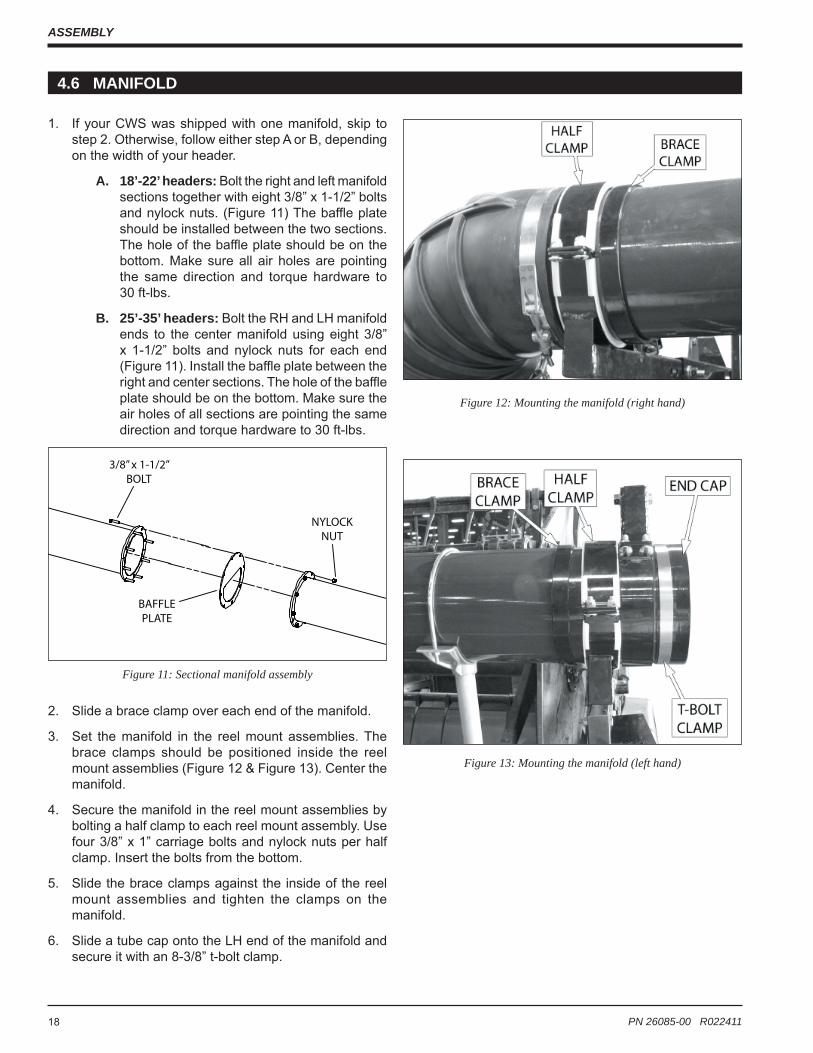
1. If your CWS was shipped with one manifold, skip to step 2. Otherwise, follow either step A or B, depending on the width of your header.
A. 18’-22’ headers: Bolt the right and left manifold sections together with eight 3/8” x 1-1/2” bolts and nylock nuts. (Figure 11) The baffle plate should be installed between the two sections. The hole of the baffle plate should be on the bottom. Make sure all air holes are pointing the same direction and torque hardware to 30 ft-lbs.
B. 25’-35’ headers: Bolt the RH and LH manifold ends to the center manifold using eight 3/8” x 1-1/2” bolts and nylock nuts for each end (Figure 11). Install the baffle plate between the right and center sections. The hole of the baffle plate should be on the bottom. Make sure the air holes of all sections are pointing the same direction and torque hardware to 30 ft-lbs.
2. Slide a brace clamp over each end of the manifold.
3. Set the manifold in the reel mount assemblies. The brace clamps should be positioned inside the reel mount assemblies (Figure 12 & Figure 13). Center the manifold.
4. Secure the manifold in the reel mount assemblies by bolting a half clamp to each reel mount assembly. Use four 3/8” x 1” carriage bolts and nylock nuts per half clamp. Insert the bolts from the bottom.
5. Slide the brace clamps against the inside of the reel mount assemblies and tighten the clamps on the manifold.
6. Slide a tube cap onto the LH end of the manifold and secure it with an 8-3/8” t-bolt clamp.
Figure 11: Sectional manifold assembly
Figure 12: Mounting the manifold (right hand)
Figure 13: Mounting the manifold (left hand)
3/8” x 1-1/2” BOLT
BAFFLE PLATE
NYLOCK NUT
19 PN 26085-00 R022411
ASSEMBLY
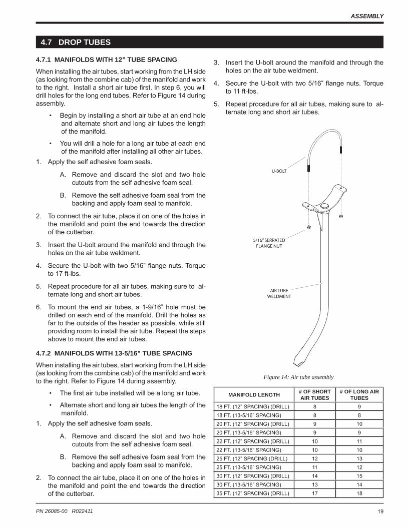
4.7.1 MANIFOLDS WITH 12” TUBE SPACING
When installing the air tubes, start working from the LH side (as looking from the combine cab) of the manifold and work to the right. Install a short air tube fi rst. In step 6, you will drill holes for the long end tubes. Refer to Figure 14 during assembly.
• Begin by installing a short air tube at an end hole and alternate short and long air tubes the length of the manifold.
• You will drill a hole for a long air tube at each end of the manifold after installing all other air tubes.
1. Apply the self adhesive foam seals.
A. Remove and discard the slot and two hole cutouts from the self adhesive foam seal.
B. Remove the self adhesive foam seal from the backing and apply foam seal to manifold.
2. To connect the air tube, place it on one of the holes in the manifold and point the end towards the direction of the cutterbar.
3. Insert the U-bolt around the manifold and through the holes on the air tube weldment.
4. Secure the U-bolt with two 5/16” flange nuts. Torque to 17 ft-lbs.
5. Repeat procedure for all air tubes, making sure to al-ternate long and short air tubes.
6. To mount the end air tubes, a 1-9/16” hole must be drilled on each end of the manifold. Drill the holes as far to the outside of the header as possible, while still providing room to install the air tube. Repeat the steps above to mount the end air tubes.
4.7.2 MANIFOLDS WITH 13-5/16” TUBE SPACING
When installing the air tubes, start working from the LH side (as looking from the combine cab) of the manifold and work to the right. Refer to Figure 14 during assembly.
• The first air tube installed will be a long air tube.
• Alternate short and long air tubes the length of the manifold.
1. Apply the self adhesive foam seals.
A. Remove and discard the slot and two hole cutouts from the self adhesive foam seal.
B. Remove the self adhesive foam seal from the backing and apply foam seal to manifold.
2. To connect the air tube, place it on one of the holes in the manifold and point the end towards the direction of the cutterbar.
AIR TUBE WELDMENT
5/16” SERRATED FLANGE NUT
U-BOLT
Figure 14: Air tube assembly
MANIFOLD LENGTH # OF SHORT AIR TUBES
# OF LONG AIR TUBES
18 FT. (12” SPACING) (DRILL) 8 918 FT. (13-5/16” SPACING) 8 820 FT. (12” SPACING) (DRILL) 9 1020 FT. (13-5/16” SPACING) 9 922 FT. (12” SPACING) (DRILL) 10 1122 FT. (13-5/16” SPACING) 10 1025 FT. (12” SPACING (DRILL) 12 1325 FT. (13-5/16” SPACING) 11 1230 FT. (12” SPACING) (DRILL) 14 1530 FT. (13-5/16” SPACING) 13 1435 FT. (12” SPACING) (DRILL) 17 18
4.7 DROP TUBES
3. Insert the U-bolt around the manifold and through the holes on the air tube weldment.
4. Secure the U-bolt with two 5/16” flange nuts. Torque to 11 ft-lbs.
5. Repeat procedure for all air tubes, making sure to al-ternate long and short air tubes.

20 PN 26085-00 R022411
ASSEMBLY
8-11/16"T-BOLT CLAMP
45 DEG.ELBOW
8-3/8"T-BOLT CLAMP
ELBOWSUPPORT BAND
ELBOWSUPPORT BAND
FLEX HOSE
42" MANIFOLD
8-11/16"T-BOLT CLAMP
8-3/8"T-BOLT CLAMP
U-BOLTBOLT, 1/2 X 3-3/4 HEX
BOLT, 3/8 X 3 HEX
90 DEG.ELBOW
TUBE MOUNTWELDMENT
STOP LATCHBRACKET
1. Using the provided 3/8” x 2-1/2” bolts, washers and nylock nuts, install the two tube mount weldments to existing holes in the OEM RH reel arm (Figure 15). The cradle of each weldment should point upward. Torque hardware to 30 ft-lbs.
2. Set the 42” aluminum manifold in the tube mount weld-ments. Position the manifold so that the back end is about even with the back panel of the header. Secure the manifold in the weldment with two 5/16” u-bolts, washers and serrated flange nuts.
3. Slide an 8-11/16” t-bolt clamp over each end of the 45 degree elbow.
4. Slide the 45 degree elbow over the air outlet of the fan. Point the elbow toward the 42” manifold.
5. Insert an elbow support band from the flex hose into the 45 degree elbow.
6. Determine the length of hose needed to connect the fan to the 42” manifold and cut the hose. Do not leave slack in this portion of flex hose.
4.8 FAN HOSE ASSEMBLY
7. Install the flex hose onto the back end of the 42” mani-fold with an 8-3/8” t-bolt clamp.
8. Slide an 8-11/16” t-bolt clamp over each end of the 90 degree elbow.
9. Slide the 90 degree elbow over the right end of the CWS manifold. Point the elbow toward the 42” manifold.
10. Insert the remaining elbow support band into the 90 degree elbow.
11. With the remaining hose, determine the length needed to reach the 42” manifold and cut the hose. Leave enough slack in this portion of flex hose to allow the reel to fully extend.
12. Install the flex hose onto the front end of the 42” mani-fold with an 8-3/8” t-bolt clamp.
13. Tighten all t-bolt clamps.
Figure 15: Fan hose installation

21 PN 26085-00 R022411
ASSEMBLY
1. Mount the switch plate assembly in a convenient place inside the cab (use either velcro or bolts).
2. Run the red wires with fuse (15 Amp & 6 Amp) to a power source. Use the actuator switch harness if pro-vided and the combine is equipped with the same type of auxiliary power supply.
3. Run the black wires to a suitable ground or to the actua-tor switch harness ground wires.
4. Route the long harnesses along the combine and header to the actuators (15 Amp Manifold Tilt; 6 Amp Air Volume) and plug in.
5. Mount the intermediate harness connectors to a con-venient location on the combine feederhouse.
Figure 16: Electrical wiring
SWITCH/MOUNT PLATE ASSEMBLY(MOUNT INSIDE COMBINE CAB)
FAN BUTTERFLY ACTUATOR(TO 6 AMP HARNESS)
MANIFOLD TILT ACTUATOR(TO 15 AMP HARNESS)
ACTUATOR SWITCH HARNESS(USED ONLY IF COMBINE EQUIPPED WITHSAME AUXILIARY POWER PLUG)(RED WIRES TO FUSE WIRES/BLACK TO GROUND)
4.9 ELECTRICAL WIRING
WARNINGPlace all controls in neutral or off, lower header to the ground, stop combine engine, set parking brake, remove ignition key, chock wheels and wait for all moving parts to stop before servicing, adjusting, repairing, or unplugging.
NOTEDisconnect the intermediate harness connector at the feederhouse when the header is disconnected from the combine.

22 PN 26085-00 R022411
ASSEMBLY
4.10 ELECTRIC ACTUATOR
1. Adjust reel arm mounts to desired position and torque all 1/2” hardware to 75 ft-lbs.
2. Slide the pivot clamp onto the LH end of the manifold (Figure 17). Loosely tighten the 3/8” x 1-1/2” bolts and nuts.
3. Attach the base end of the electric actuator to the reel mount assembly with a 1/2” x 2-1/2” bolt and locknut.
4. Adjust the manifold so the air tubes point directly be-hind the cutterbar. The reel tines should extend past the air tubes. Manually turn the reel to ensure that the tines follow the curve of the air tubes as they rotate downward (Figure 18).
5. Extend the actuator rod 2 inches.
6. Bolt the actuator rod to the clevis on the pivot clamp with a 1/2” x 2-1/2” bolt and locknut.
7. Tighten the pivot clamp hardware once the manifold and air tubes are properly positioned.
Figure 17: Electric actuator
Figure 18: Air tube adjustment

23 PN 26085-00 R022411
ASSEMBLY
4.11 OPTIONS
4.11.1 GEARBOX/FAN EXTENSION
The gearbox/fan extension option is designed to extend the fan up to eliminate clearance problems with headers smaller than 20’ and combines with dual tires. When installing the gearbox fan extension kit, follow this procedure.
1. Separate gearbox and fan. Refer to Figure 19.
A. Loosen the set screw securing the indicator weldment and remove from butterfly shaft.
B. Remove 3/8” x 1-1/4” bolts connecting fan housings and separate.
C. Loosen 3/4” castle nut and remove washer and nut from gearbox shaft.
D. Remove fan rotor and spacer washers.
E. Remove bolts connecting lower fan housing to gearbox flange.
2. Attach extension shaft/hub assembly.
A. Bolt extension shaft/hub assembly to gearbox flange with 1/2” x 1” bolts. Rotate extension shaft so the key in the coupler at the bottom of the shaft lines up with the keyway on the gearbox shaft.
B. Place bearing retainer plate and washers onto end of extension shaft/hub assembly.
C. Bolt lower fan housing to extension flange with 1/2 x 1” bolts.
D. Attach spacer washers and fan rotor to exten-sion shaft and secure with washer and 3/4” castle nut.
E. Bolt upper fan housing to lower fan housing with 3/8” x 1-1/4” bolts.
F. Reinstall indicator weldment onto butterfly shaft and tighten set screw.
3. Mount gearbox/fan extension to combine.
A. Refer to Section 4.5 for fan/gearbox installation instructions.
B. Select appropriate support bracket for combine model.
C. Bolt mounting bracket onto header.
D. Remove upper RH bolt on gearbox mount plate. Bolt support bracket in the location bolt was removed using provided 1/2” X 1-1/2” bolt.
E. Attach gearbox/fan extension to support bracket with provided u-bolt.
F. Operate the CWS as instructed in this manual.
WARNINGPlace all controls in neutral or off, lower header to the ground, stop combine engine, set parking brake, remove ignition key, chock wheels and wait for all moving parts to stop before servicing, adjusting, repairing, or unplugging.

24 PN 26085-00 R022411
ASSEMBLY
4.11 OPTIONS
Figure 19: Gearbox/fan extension
1
2
34
56
7
8
9
10
11
5
12
13
14
15
16
17
18
19
20
21
22
23
24
25
KIT, GEARBOX/FAN EXTENSION OPTION
ITEM PART NUMBER DESCRIPTION QTY
1 7022 KEY, 3/16” SQUARE X 1-1/4” PLAIN 12 13014 U-BOLT, 3/8” X 3” X 4”, FAN MOUNT ZP 13 15006 BOLT, 3/8” X 1” HHCS GR5 ZP 14 15012 BOLT, 1/2” X 1” HHCS GR5 ZP 15 15014 BOLT, 1/2” X 1-1/2” HHCS GR5 ZP 86 15031 WASHER, 3/8” FLAT ZP 27 15042 NUT, 3/8” HEX NC ZP 28 15049 NUT, 1/2” CENTERLOCK GR8 ZP 89 15051 NUT, 3/8” SERRATED FLANGE NC ZP 12
10 15055 NUT, 3/4” NF CASTLE ZP 111 15097 WASHER, 1/2” SAE FLAT ZP 812 15098 WASHER, 3/4” SAE FLAT ZP 113 15099 WASHER, 7/8” SAE FLAT ZP 2
KIT, GEARBOX/FAN EXTENSION OPTION
ITEM PART NUMBER DESCRIPTION QTY
14 15332 SCREW, 1/4”-20 X 1/4” SET 115 15364 BOLT, 3/8” X 1-1/4” HHCS GR5 ZP 12
16 16466 ROTOR, FAN, 12.88” X 2.5”, 7/8”B, CW, HSPD, ALUM 1
17 21193 8” FAN, SIDE W/BUTTERFLY, RH 118 21194 8” FAN, SIDE W/BUTTERFLY, LH 119 21444 PLATE, LARGE BUTTERFLY 120 22344 WELDMENT, INDICATOR 121 24510-12 PLATE, BEARING RETAINER 122 24639-12 BRACKET, EXTENSION SUPPORT 123 24640-12 BRACKET, EXTENSION SUPPORT 124 24641-12 BRACKET, EXTENSION SUPPORT 125 24643 ASSEMBLY, EXTENSION SHAFT/HUB 1

25 PN 26085-00 R022411
Section OPERATION5
1. Read and understand the owner’s manual and all safety signs before servicing, adjusting or repairing.
2. Install and secure all guards and shields before starting or operating.
3. Keep hands, feet, hair and clothing away from all moving and/or rotating parts.
4. Place all controls in neutral or off, lower header to the ground, stop combine engine, set parking brake, chock wheels, remove ignition key and wait for all moving parts to stop before servicing, adjusting, repairing or unplugging.
5. Clear the area of bystanders, especially small chil-dren, before starting.
WARNING6. Keep all hydraulic lines, fittings, and couplers tight
and free of leaks before and during use.
7. Clean reflectors and lights before transporting.
8. Review safety related items annually with all person-nel who will be operating or maintaining the machine.
9. Shut the combine off when connecting the machine hydraulics.
10. Do not exceed fan speed of 5300 RPM. Check the fan speed by multiplying the driveline speed (RPM) by the gear ratio of the gearbox.
11. Do not run the fan without back pressure. Close the butterfly valve on the fan if the flex hose is discon-nected.
Many features incorporated into this machine are the result of suggestions made by customers like you. Read this manual carefully to learn how to operate the machine safely and how to set it to provide maximum effi ciency. By following the operating instructions in conjunction with a good maintenance program, your CWS will provide many years of trouble-free service.
The CWS is designed to dramatically improve harvesting effi ciency. Be familiar with the machine before starting.
It is the responsibility of the owner or operator to read this manual and to train all other operators before they start working with the machine. Hazard control and accident prevention are dependent upon the awareness of personnel involved in the operation of the CWS.
Follow all safety instructions exactly. Safety is everyone’s business. By following recommended procedures, a safe working environment is provided for the operator, bystand-ers and the area around the work site. Untrained operators are not qualifi ed to operate the machine.

26 PN 26085-00 R022411
OPERATION
The CWS is designed to handle all types of beans and small grains such as wheat and barley.
The CWS stationary air tubes deliver a constant stream of high velocity air which fi rmly pushes the crop off the cutterbar, over the platform and to the auger. To generate the high velocity air, power is provided by the combine feeder shaft. The gearbox provides rotational power to the high pressure fan.
Figure 20: Machine components
5.1 MACHINE COMPONENTS

27 PN 26085-00 R022411
OPERATION
5.2 INITIAL ADJUSTMENTS
At the end of the season, or before any long period of non-use, loosen the center locknuts to relieve the pres-sure on the linings.
NOTE
Figure 21: Adjusting the torque limiter
CENTER LOCKNUTS
5.2.1 MANIFOLD ADJUSTMENT1. Adjust your header and pickup reel per the manufac-
turer’s recommendations.
2. Position air manifold to maintain clearance between air tubes and reel bats/tines.
3. Adjust the air tube position to point at the back of the sickle bar. This adjustment refers to the longer air tubes on Crary Wind Systems.
4. Loosen tilt actuator clamp and adjust so the actua-tor is in middle of stroke (approx. 2” of actuator shaft exposed) with tube nozzles pointed at the back of the sickle bar. Retighten clamp.
5. Make sure air tubes do not hit ground when reel is at its lowest operating position. Adjust as required.
5.2.2 TORQUE LIMITER (SLIP CLUTCH)
The CWS comes equipped with a torque limiter (slip clutch) on the main drive of the CWS. The torque limiter is set in the engaged position from the factory. Before use, the slip clutch must be slipped and adjusted to ensure proper function.
ALLOWING THE TORQUE LIMITER TO SLIP1. Loosen the center locknuts (Figure 21) on the torque
limiter so that the pressure is relieved from the pres-sure plates.
2. With the combine engine at idle speed, engage the PTO for 2-3 seconds to make the torque limiter slips. Do not allow the torque limiter to slip for more than 2-3 seconds at a time to prevent damage to the linings.
3. If the torque limiter does not slip, repeat the procedure 2 or 3 times. If it still doesn’t slip, check that all the center locknuts are loosened and not placing tension on the pressure plates.
4. After the torque limiter has slipped, refer to the next section for instructions on how to reset the torque limiter.
WARNINGPlace all controls in neutral or off, lower header to the ground, stop combine engine, set parking brake, remove ignition key, chock wheels and wait for all moving parts to stop before servicing, adjusting, repairing, or unplugging.
WARNINGTo prevent burn-up of slip disks the torque limiter (slip clutch must be adjusted prior to use.
ADJUSTING THE TORQUE LIMITERAfter the torque limiter has slipped, it must be adjusted to the tension required to operate the header. The goal of this procedure is to have the torque limiter slip momentarily upon initial startup and then operate normally. The slip clutch must not slip at full RPM.1. Slowly engage the PTO with the engine running at idle
speed.
2. If the torque limiter does not slip, shut off machine and loosen the center locknuts in 1/4 turn increments until it slips momentarily when the header is engaged. If the torque limiter continues to slip after start-up, tighten the center locknuts in 1/4 turn increments until it slips momentarily when the header is engaged.
3. The torque limiter is ready for use.

28 PN 26085-00 R022411
OPERATION
5.3 PRE-OPERATION CHECKLIST 5.4 MACHINE BREAK-IN
Effi cient and safe operation of the CWS requires that each operator reads and understands the operating procedures and all related safety precautions outlined in this section. A pre-operation checklist is provided for the operator. It is important for both personal safety and maintaining the good mechanical condition of the machine that this checklist is followed.
Before operating the machine and each time thereafter, the following areas should be checked off:1. Service the machine per the schedule outlined in the
Service Record.
2. Use only a combine of adequate power and specifica-tions to operate the machine.
3. Check that all guards are installed, secured and func-tioning as intended. Do not operate with missing or damaged shields.
4. Ensure that the machine is properly attached to the header and that mechanical retainers, such as quick pins, are installed.
5. Check the cutterbar, reel area and drives for entangled material.
6. Check the chains and sprockets for proper tension and alignment. Adjust as required.
7. Visually inspect the hydraulic system for leakage, loose fittings, and damaged hoses. Tighten fittings, replace damaged components and wipe up leaked or excess hydraulic fluid.
8. Check condition of driveline slip clutch friction discs. If installing replacement discs, adjust spring height to original height. Deviation from original setting may be needed depending upon disc wear. Run-in is recom-mended at the start of the season (see Service and Maintenance section).
5.4.1 PRE-START INSPECTION1. Read the Operator’s Manual.
2. Check that the hydraulic lines and electrical harnesses are routed where they will not contact moving parts. Be sure all components are clipped, taped or tied securely in place.
3. Check that all required nuts and bolts are installed and tightened to their specified torque.
5.4.2 AFTER OPERATING FOR 2 HOURS1. Re-torque fasteners and hardware.
2. Check that all safety decals are installed and legible. Apply new decals if required.
3. Check that no hydraulic hoses are being pinched, crimped, or are rubbing. Reroute as required.
4. Check that the wiring harness is not being pinched, crimped, or rubbing. Reroute as required.
5. Check the tension and alignment of all drive chains. Adjust as required.
6. The gearbox will generate heat. The typical operating temperature of the gearbox is 180° F.
5.4.3 AFTER OPERATING FOR 10 HOURS:1. Re-torque fasteners and hardware.
2. Check that all guards are installed, secured and func-tioning as intended. Do not operate with missing or damaged shields.
3. Check safety decals. Install new ones if required.
4. Check the routing of hydraulic lines and the wiring harness. Reroute as required to prevent pinching, crimping, binding, or rubbing.
5. Refer to the normal servicing and maintenance sched-ule as defined in the Service Record.

29 PN 26085-00 R022411
OPERATION
Figure 22: Manifold tilt and fan air volume toggle switch
MANIFOLD TILTTOGGLE SWITCH
FAN AIR VOLUMETOGGLE SWITCH
Figure 23: Air fl ow
ADJUSTMENT STRAP
ARM MOUNT TUBE
REEL MOUNT
PIVOT CLAMP
CUTTER BAR
ELECTRICACTUATOR
FAN BUTTERFLY ACTUATOR
BUTTERFLY
INDICATOR (SHOWN FULLY CLOSED POSITION)
INDICATOR (FULLY OPEN POSITION)
Figure 24: Fan butterfl y actuator
5.5 CONTROLS
Before starting to work, all operators should familiarize themselves with the location and function of the controls and safety devices. Some machines may vary due to dif-ferent models of combines and headers. Refer to Figure 22 through Figure 24.
MANIFOLD TILT:1. Moving the toggle switch to the FORE position extends
the shaft of the electric actuator forward. This rotates the manifold CW which directs the air tubes towards the back of the header.
2. Moving the toggle switch to the AFT position retracts the shaft of the electric actuator backward. This rotates the manifold CCW, which directs the air tubes towards the front of the header.
FAN AIR VOLUME ACTUATOR:1. Move the toggle to the OPEN position to open the but-
terfly plate which increases air volume to the air tubes.
2. Move the toggle to the CLOSED position to close the butterfly plate which decreases air volume to the air tubes.
REEL LIFT/FORE AND AFT ADJUSTMENT:Consult your owner/operator’s manual that came with your header.
5.5 CONTROLS

30 PN 26085-00 R022411
OPERATION
5.6 OPERATING HINTS
The following are recommended adjustments the operator can make based on crop conditions. Any adjustments that involve the operator leaving the combine cab should heed the warning instructions listed below.
1. Increase air to maximum.
2. Move tilt control until air is directed at back of sickle bar with reel feeding properly.
3. Gradually reduce air until crop is no longer flowing smoothly across sickle.
4. Gradually increase air until smooth crop flow across the sickle is achieved.
5. Remember: more air uses more horsepower.
6. Gradually adjust air position fore and aft until optimum crop flow is achieved.
7. Gradually reduce air further until minimum air is used to maintain crop flow.
5.7 TRANSPORTING
The CWS is designed to be easily and conveniently moved from location to location. When transporting the machine, review and follow these safety instructions:1. Make sure you are in compliance with all local regula-
tions regarding transporting equipment on public roads and highways.
2. It is the responsibility to the owner to know the lighting and marking requirements of the local highway authori-ties and to install and maintain the equipment to provide compliance with the regulations. Add extra lights when transporting at night or during periods of limited visibility.
3. See the owner’s manual that came with your combine and header for proper transportation guidelines.
WARNINGPlace all controls in neutral or off, lower header to the ground, stop combine engine, set parking brake, remove ignition key, chock wheels and wait for all moving parts to stop before servicing, adjusting, repairing, or unplugging.
DO use the reel to bring the crop into the header.
DO use air to feed crop across the sickle.
DO adjust air tube angle to maximize crop fl ow across the sickle.
DO make adjustments gradually.
DO verify proper air tube position whenever adjusting reel height or fore and aft position.
DO SHUT OFF AIR IMMEDIATELY IF THE AIR HOSE SHOULD FAIL. FAILURE TO DO SO MAY RESULT IN GEARBOX FAILURE.
DO follow troubleshooting guide one step at a time.
DO NOT operate with air hose disconnected.
DO NOT operate with tines striking the ground or sickle.
DO NOT use more air than needed.
DO NOT operate with plugged air tubes.

31 PN 26085-00 R022411
OPERATION
After the season’s use, the machine should be thoroughly inspected and prepared for storage. Repair or replace any worn or damaged components to prevent any unnecessary down time at the start of next season. To ensure a long, trouble free life, this procedure should be followed when preparing the unit for storage.1. Clear the area of bystanders, especially small children.
2. Thoroughly wash the entire machine using a pressure washer to remove all dirt, mud, debris or residue.
3. Inspect the following components:
A. PTO Driveline Components
• Check the condition and operation of the fric-tion disc torque limiter (slip clutch) (see the maintenance section).
• Release slip clutch pressure.
• Store in a dry place.B. Electrical System
• Check the wiring harness and all wiring com-ponents for damaged or worn areas.
• Check for cracked or worn insulation.
• Replace any components that have come in contact with moving parts and re-route to pre-vent damage in the future.
C. CWS Components:
• Air tubes: repair or replace bent or damaged air tubes.
D. Fan Components
• Visually inspect fan rotor for wear or build-up.
• Check condition of the rotary screen bearings.4. Make a list of all parts needed for repairs and order
them immediately. Repairs can then be done when time permits to prevent unnecessary down time at the start of next season.
5. Lubricate all grease points to remove any water residue from the washing and prevent rusting during the storage period. Rotate all moving parts to distribute lubricant to all surfaces.
6. Apply a light coat of grease on the shafts.
7. Check the cutterbar, reel area and drives for entangled material.
8. Touch up all paint nicks and scratches to prevent rust-ing.
9. Move the machine to its storage area.
10. Select an area that is dry, level, and free of debris.
11. If the machine cannot be stored inside, cover with a waterproof tarpaulin and tie securely in place.
12. Store out of the way of human activity.
13. Do not allow children to play on or around stored unit.
REMOVING FROM STORAGEWhen removing from storage and preparing to use, follow this procedure:1. Clear the area of bystanders, especially small children.
2. Remove the tarpaulin from the machine if it was cov-ered.
3. Clean off accumulated trash and dirt.
4. Check routing and securing of all hydraulic lines and wiring harness. Adjust as required.
5. Rotate all components and systems by hand to see that none are seized. Loosen any seized components with penetrating oil before starting.
6. Retighten any loose bolts to their specified torque.
7. Lubricate all grease points and shaft surfaces.
8. Check for excessive wear on all moving parts.
9. Tighten all hydraulic connections and mounts. Replace o-rings, fittings, or connectors subject to leaking.
10. Review and follow all items in the machine break-in section before starting (Section 5.4).
11. Install all safety shields and review precautions with operators and other personnel involved in the operation.
12. Drain and refill gearbox lube.
13. Readjust the torque limiter on main driveline.
5.8 STORAGE

32 PN 26085-00 R022411
SERVICE & MAINTENANCESection6
These service recommendations are based on normal operating conditions. Severe or unusual conditions may require more frequent attention. Copy this page to continue record.
ACTION CODE: √ = CHECK OR INSPECT CL = CLEAN L = LUBRICATE C = CHANGE
HOURS
SERVICED BY
DAILY
L PTO CROSS JOURNAL ZERKS
√ GEARBOX OIL LEVEL
16 HOURS
L PTO INNER TUBE
40 HOURS
L PTO SHIELD RETAINING BEARING
L PTO DISCONNECT MECHANISM
√ FAN HOUSING AND AIRWAY
YEARLY
C GEARBOX LUBE
√ CONDITION OF FRICTION DISC TORQUE LIMITER (SLIP CLUTCH)
6.1 MAINTENANCE CHECKLIST

33 PN 26085-00 R022411
SERVICE & MAINTENANCE
1. Use the maintenance checklist provided to keep a record of all scheduled maintenance.
2. Use a hand-held grease gun for all greasing.
3. Wipe grease fitting with a clean cloth before greasing to avoid injecting dirt and grit.
4. Replace and repair broken fittings immediately.
5. If fittings will not take grease, remove and clean thor-oughly. Also, clean lubricant passageway. Replace fitting if necessary.
6.2 FLUIDS AND LUBRICANTS
Along with a servicing interval, perform a visual inspection. Maintenance personnel can often detect potential problems from any unusual sounds made by such components as shafts, bearings and drives.1. GREASE: Use an SAE multipurpose high temperature
grease with extreme pressure (EP) performance meet-ing or exceeding the NLGI #2 rating for all requirements. Also acceptable is an SAE multipurpose lithium based grease.
2. GEARBOX LUBE: Use Mobilube HD SAE 75W-90 Gear lube or equivalent with the following specifications:
API Service GL-5MIL-L-2105DMACK GO-HCapacity: 40 oz. (1.2 L)
1. STORING LUBRICANTS: Your machine can operate at top efficiency only if clean lubricants are used. Use clean containers to handle all lubricants. Store them in an area protected from dust, moisture and other contaminants.
6.3 GREASING
6.4 GEARBOX OIL
CHECKING THE GEARBOX OIL LEVELCheck the gearbox oil level daily. Check more frequently if leaks exist around any of the plugs or shaft seals.
The oil level in the gearbox should be no higher than the bottom of the drive shaft.
CHANGING THE GEARBOX OIL Each gearbox is equipped with a drain, level and fi ll plug. Every 500 operating hours or annually, whichever comes fi rst, the oil should be replaced. When changing the oil, follow this procedure:1. Place a container under the gearbox.
2. Remove the drain plug. Allow 10 minutes to drain.
3. Replace the drain plug.
4. Add 40 oz of Mobilube SHC 75W-90 synthetic gear lube or equivalent with the following specifications:
API Service GL-5/MT.1MIL-L-2105DMACK GO-J PLUSSAE J2360Capacity: 40 oz. (1.2 L)
5. Fil l the gearbox oil through the top f i l l plug (Figure 25).
6. Check that the air passage through the vent plug is open.
7. Dispose of the used oil in an environmentally safe manner.
Figure 25: Gearbox oil level
IMPORTANTAlways clean the vent plug if any leaks are noticed around shaft seals.

34 PN 26085-00 R022411
SERVICE & MAINTENANCE
DAILYLubricate PTO cross journals (Figure 26). Make sure grease purges through all four bearings.
EVERY 16 HOURSLubricate PTO inner tubes (Figure 26). Telescoping mem-bers must have lubrication to operate successfully. Tele-scoping members without fi ttings should be pulled apart and grease should be added manually with a brush.
EVERY 40 HOURSLubricate the PTO shield retaining bearing. Molded nipples on the guard near each guard bearing are intended as grease fi ttings and should be lubricated every 40 hours of operation (Figure 26).
Lubricate the PTO disconnect mechanism.
Figure 27: Fan housing/airway
8h8h
16h
40h 40h
6.5 PTO LUBRICATION
Figure 26: Driveline lubrication
Every 40 hours the fan housing and airway should be checked for wear or plugging (Figure 27).
6.6 FAN HOUSING AND AIR HOSE
6.7 TORQUE LIMITER (SLIP CLUTCH)
1. Disconnect the PTO driveline from the implement (Figure 28).
2. Position the driveline on a workbench.
3. Loosen the eight slip clutch nuts.
4. Remove bolts and disassemble all components.
5. Check the condition of all parts, especially the friction discs (Figure 29).
6. If replacement parts are needed, consult your local authorized Crary dealer.
7. Reassemble all components.
8. Tighten nuts following an alternating cross pattern until the clutch slips momentarily upon initial startup and then continues to operate normally.
Figure 28: Torque limiter (slip clutch)
Figure 29: Slip clutch components

35 PN 26085-00 R022411
In the following section, we have listed many of the problems, causes and solutions to the problems that you may encounter.
If you encounter a problem that is diffi cult to solve, even after having read through this troubleshooting section, please call your local Crary dealer. Before you call, please have this operator’s manual and the serial number from your ma-chine ready.
PROBLEM POSSIBLE CAUSE REMEDY
Cut crop building up and falling from front of cutter bar or loss of grain heads at cutter bar.
Reel not adjusted low enough for proper delivery of cut crop to auger.
Set reel low enough to sweep material from cutter bar.
Insuffi cient ledge for crop travel. Extend rigid cutter bar.
Auger clearance too high from platform bottom.
Adjust outer ends of auger to 1/2” (13 mm) of clearance of platform bottom and check fi nger clearance.
Insuffi cient airfl ow or misdirection of airfl ow from manifold to clean off cut-ter bar.
Adjust manifold so that air flow is directed more at cutter bar to keep it clean.
Clean debris from rotary screen.
Check for and clear obstruction from fl ex hose or manifold.
Check butterfl y position and open to allow more air fl ow.
Check fan RPM, adjust combine shaft speed and check for proper gearbox ratio for combine
Reel speed too slow. Increase speed of reel.Reel is positioned too high. Move reel back and then down.
Build up of grain on cutterbar.Lower height of reel and set fore-and-aft position as close as possible to cutter bar and auger.
Uneven or bunched feeding of crop to cylinder.
Feeder chain carrying straw back around and disrupting crop fl ow to the cylinder.
Extend feederhouse stripper down to stop straw from fi ltering back out.
Crop “tailing in” to the auger (heads not feeding fi rst).
Rotate manifold so that air fl ow is di-rected higher on the crop.
Cutter bar not at recommended speed. Check basic speed of combine (see combine owner’s manual)
TROUBLESHOOTINGSection7
BEFORE YOU CALLPlease have the following information available:
Serial # ________________________ ______
7.1 GENERAL TROUBLESHOOTING

36 PN 26085-00 R022411
TROUBLESHOOTING
Gearbox leaking or overheating.Incorrect oil type or level. Check level and replace if necessary.Breather plugged. Remove breather, clean and reinstall.Seals are leaking. Install new seal kit.
Rotary screen plugs.
Debris is pinched between the base and the screen, stopping the motor. Adjust air base closer to the screen.
Screen cleaner not adjusted properly. Adjust the screen cleaner to revolve close to the screen, but not touching it.
Needs Rotary Screen Wrap.
Contact Crary Dealer for Rotary Screen Wrap (PN 25592-12). This wrap will prevent debris from becom-ing lodged between the base and the rotary screen.
7.1 GENERAL TROUBLESHOOTING

37 PN 26085-00 R022411
Section SPECIFICATIONS8
Efficiency
Pressure
Horsepower
4000300020001000CFM
10
20
30
40
50
4500 RPMFORWARD CURVE8" OUTLET FAN
ROTOR SIZE =16.50" DIA X 3.00" WIDE
STA
TIC
PR
ES
SU
RE
HO
RS
EP
OW
ER
& E
FFIC
IEN
CY
%
10
30
20
40
50
8.1 FAN PERFORMANCE DATA

38 PN 26085-00 R022411
SPECIFICATIONS
CHECKING BOLT TORQUE:The table shown below is for reference purposes only and its use by anyone is entirely voluntary, unless otherwise noted. Reliance on its contents for any purpose is at the sole risk of that person. Crary Co. is not responsible for any loss claim or damage arising therefrom. In developing these tables, Crary has made a determined effort to present the contents accurately.
Torque fi gures indicated are valid for non-greased or non-oiled threads and heads unless otherwise specifi ed. Therefore, do not grease or oil bolts or cap screws unless otherwise specifi ed in this manual. When using locking elements, increase torque values by 5%.
* Torque value for bolts and capscrews are identifi ed by their head markings.
ENGLISH
BOLT DIAMETERBOLT TORQUE *
SAE 2 SAE 5 SAE 8N.m Ft-lb. N.m Ft-lb. N.m Ft-lb.
1/4” 7.5 5.5 11 8 16 125/16” 15 11 23 17 34 253/8” 27 20 41 30 61 45
7/16” 41 30 68 50 95 701/2” 68 50 102 75 149 110
9/16” 97 70 149 110 203 1505/8” 122 90 203 150 312 2303/4” 217 160 353 260 515 3807/8” 230 170 542 400 814 6001” 298 220 786 580 1220 900
1-1/8” 407 300 1085 800 1736 12801-1/4” 570 420 2631 1940 2468 1820
METRIC
BOLT DIAMETERBOLT TORQUE *
4.8 8.8 10.9 12.9N.m Ft-lb. N.m Ft-lb. N.m Ft-lb. N.m Ft-lb.
M3 0.5 0.4 - - - - - -M4 3 2.2 - - - - - -M5 5 4 - - - - - -M6 6 4.5 11 8.5 17 12 19 14.5M8 15 11 28 20 40 30 47 35
M10 29 21 55 40 80 60 95 70M12 50 37 95 70 140 105 165 120M14 80 60 150 110 225 165 260 190M16 125 92 240 175 350 255 400 300M18 175 125 330 250 475 350 560 410M20 240 180 475 350 675 500 800 580M22 330 250 650 475 925 675 1075 800M24 425 310 825 600 1150 850 1350 1000M27 625 450 1200 875 1700 1250 2000 1500
SAE - 8SAE - 2
A
SAE - 5SAEGradeandHeadMarkings
BOLT DIAMETER
10.94.8
A
8.8METRICGradeandHeadMarkings
BOLT DIAMETER12.9
4.8 8.8 10.9 12.9
8.2 BOLT TORQUE

39 PN 26085-00 R022411

237 12th St. NW • P.O. Box 849West Fargo, ND 58078-0849
PH: 1-800-247-7335 • FAX: (701)282-9522www.crary.com