Embed Size (px)
Citation preview

Instruction ManualFirmware Rev.: 269P.D6.0.4Manual P/N: 1601-0013-D3Copyright 1999 GE Multilin
CANADA215 Anderson Avenue, Markham, Ont., L6E 1B3Tel. (905) 294-6222 Fax. (905) 294-8512Internet: http://www.ge.com/edc/pm
269 PlusMOTOR MANAGEMENT RELAY ®
TABLE OF CONTENTS
i
1 INTRODUCTION1.1 Motor Protection Requirements................. 1-11.2 269 Plus Relay Features ........................... 1-11.3 Typical Applications ................................... 1-41.4 Order Code/Information............................. 1-51.5 Technical Specifications ............................ 1-6
2 INSTALLATION2.1 Physical Dimensions ................................. 2-12.2 Mounting ................................................... 2-12.3 External Connections................................ 2-62.4 Control Power.......................................... 2-122.5 Phase CT Inputs ..................................... 2-122.6 Ground CT Input ..................................... 2-152.7 Trip Relay Contacts ................................. 2-152.8 Alarm Relay Contacts.............................. 2-162.9 Auxiliary Relay #1 Contacts .................... 2-162.10 Auxiliary Relay #2 Contacts .................. 2-162.11 RTD Sensor Connections...................... 2-172.12 Emergency Restart Terminals ............... 2-182.13 External Reset Terminals ...................... 2-182.14 Analog Output Terminals (Non-Isolated)2-182.15 Differential Relay Terminals ................... 2-182.16 Speed Switch Terminals ........................ 2-192.17 Programming Access Terminals ............ 2-192.18 RS-485 Serial Communications
Terminals................................................ 2-192.19 Display Adjustment................................ 2-202.20 Front Panel Faceplate ........................... 2-212.21 Spare Input Terminals ........................... 2-212.22 269 Plus Drawout Relay ........................ 2-212.23 Meter Option Installation ....................... 2-25
3 SETUP AND USE3.1 Controls and Indicators ............................. 3-23.2 269 Plus Relay Display Modes.................. 3-63.3 ACTUAL VALUES Mode............................ 3-63.3a Starts/Hour Timer .................................. 3-163.3b Time Between Starts Timer ................... 3-163.3c Cause of Last Trip.................................. 3-163.3d Cause of Last Event .............................. 3-163.4 SETPOINTS Mode .................................. 3-163.5 HELP Mode............................................. 3-463.6 TRIP/ALARM Mode ................................. 3-463.7 Phase CT and Motor Full Load Current
Setpoints ................................................ 3-493.8 Acceleration Time Setpoint ..................... 3-493.9 Inhibits..................................................... 3-493.10 Unbalance Setpoints ............................. 3-503.11 Ground Fault (Earth Leakage)
Setpoints ................................................ 3-533.12 Undercurrent Setpoints ......................... 3-543.13 Rapid Trip / Mechanical Jam Setpoints . 3-543.14 Short Circuit Setpoints .......................... 3-543.15 Immediate Overload Alarm Level
Setpoint.................................................. 3-553.16 Stator RTD Setpoints ............................ 3-553.17 Other RTD Setpoints ............................. 3-55
3.18 Overload Curve Setpoints ..................... 3-563.19 Thermal Capacity Alarm........................ 3-613.20 Thermal Memory ................................... 3-613.21 Emergency Restart ............................... 3-643.22 Resetting The 269 Plus Relay ............... 3-643.23 269 Plus Relay Self-Test ....................... 3-653.24 Statistical Data Features ....................... 3-653.25 Factory Setpoints .................................. 3-663.26 Meter Option ......................................... 3-66
4 COMMUNICATIONS4.1 Modes of Operation................................... 4-14.2 Physical Layer ........................................... 4-14.3 Packet Format ........................................... 4-14.4 The Handshake ......................................... 4-24.5 Supported Functions................................. 4-34.6 Exception or Error Replies ........................ 4-44.7 Error Checking Code................................. 4-4
4.7.1 CRC-16 Algorithm............................. 4-44.7.2 A Sample Packet with CRC-16............................................. 4-5
4.8 Memory Map ............................................. 4-5
5 TESTING5.1 Primary Injection Testing ........................... 5-15.2 Secondary Injection Testing ...................... 5-15.3 Phase Current Input Functions ................. 5-15.4 Ground Fault Current Functions................ 5-45.5 RTD Measurement Tests ........................... 5-45.6 Power Failure Testing ................................ 5-55.7 Analog Current Output .............................. 5-55.8 Routine Maintenance Verification.............. 5-55.9 Dielectric Strength (Hi-Pot) Test ................ 5-5
6 THEORY OF OPERATION6.1 Hardware................................................... 6-16.2 Firmware ................................................... 6-1
7 APPLICATION EXAMPLES7.1 269 Plus Relay Powered from One of Motor
Phase Inputs ............................................ 7-17.2 Loss of Control Power Due to Short Circuit or
Ground Fault ............................................ 7-17.3 Example Using FLC Thermal Capacity
Reduction Setpoint................................... 7-1
8 269PC SOFTWARE8.1 Overview ................................................... 8-18.2 Hardware and Software Requirements ..... 8-28.3 Menu Summary......................................... 8-38.4 Hardware Configuration ............................ 8-58.5 269 PC Installation .................................... 8-68.6 Startup and Communications
Configuration............................................ 8-78.7 Entering Setpoints..................................... 8-98.8 Saving Setpoints to a File ....................... 8-118.9 Loading Setpoints From a File ................ 8-12
TABLE OF CONTENTS
ii
8.10 Viewing Actual Values ........................... 8-148.11 Trending................................................. 8-16
APPENDIX A269 PLUS UNBALANCE EXAMPLE ...............A-1
APPENDIX B269 Plus Thermal Model .................................B-1269 Plus RTD Bias Feature.............................B-2
APPENDIX C269 Plus RTD Circuitry....................................C-1
APPENDIX D2I CT Configuration ........................................D-1
APPENDIX EAsymmetrical Starting Current ........................E-1
APPENDIX F269 Plus Do's and Don'ts Checklist................. F-1
APPENDIX GGround Fault and Short Circuit Instantaneous
Elements ................................................. G-1
APPENDIX HI. 269 Plus CT Withstand.................................H-1II. CT Size and Saturation ...............................H-1
APPENDIX I269 Plus Commissioning Summary ................. I-1
GLOSSARY
1 INTRODUCTION
1-1
1.1 Motor Protection Requirements
Three phase A.C. motors have become standard inmodern industry. These motors are generally ruggedand very reliable when used within their rated limits.Newer motors, however, tend to be designed to runmuch closer to these operational limits and thus, thereis less margin available for any type of abnormal sup-ply, load, or operating conditions.
In order to fully protect these motors, a modern protec-tive device is required. Accurate stator and rotor ther-mal modeling is necessary to allow the motor tooperate within its thermal limits and still give the maxi-mum desired output. As well, other features can beincorporated into a modern relay to fully protect themotor, the associated mechanical system, and themotor operator from all types of faults or overloads.
Motor thermal limits can be exceeded due to increasedcurrent from mechanical overloads or supply unbal-ance. Unbalance can greatly increase heating in therotor because of the large negative sequence currentcomponents present during even small voltage unbal-ances. A locked or stalled rotor can cause severeheating because of the associated large currents drawnfrom the supply. Many motor starts over a short periodof time can cause overheating as well. Phase-to-phaseand phase-to-ground faults can also cause damage tomotors and hazards to personnel. Bearing overheatingand loss of load can cause damage to the mechanicalload being driven by the motor.
The ideal motor protection relay should monitor therotor and stator winding temperatures exactly and shutoff the motor when thermal limits are reached. Thisrelay should have an exact knowledge of the tempera-ture and proper operating characteristics of the motorand should shut down the motor on the occurrence ofany potentially damaging or hazardous condition.
The GE Multilin Model 269 Plus Motor ManagementRelay® uses motor phase current readings combinedwith stator RTD temperature readings to thermallymodel the motor being protected. In addition, the 269Plus takes into account the heating effects of negativesequence currents in the rotor, and calculates thecooling times of the motor. The relay also monitors themotor and mechanical load for faults and problems.With the addition of a GE Multilin meter (MPM), the269 Plus may also monitor voltages and power andperform several protection functions based on thesevalues.
1.2 269 Plus Relay Features
The GE Multilin Model 269 Plus Motor ManagementRelay® is a modern microcomputer-based product de-signed to provide complete, accurate protection forindustrial motors and their associated mechanical sys-tems. The 269 Plus offers a wide range of protection,monitoring, and diagnostic features in a single, inte-grated package. All of the relay setpoints may be pro-grammed in the field using a simple 12 position keypadand 48 character alphanumeric display. A built-in"HELP" function can instruct the user on the properfunction of each of the programming keys and on themeaning of each displayed message.
One 269 Plus relay is required per motor. Phase andground fault currents are monitored through currenttransformers so that motors of any line voltage can beprotected. The relay is used as a pilot device to causea contactor or breaker to open under fault conditions;that is, it does not carry the primary motor current.
The model 269 Plus incorporates the following fea-tures: custom curve selectability, motor statistical rec-ords, speed switch input, differential relay input, 10RTD inputs, single shot emergency restart feature, anRS485 communications port, unbalance input to ther-mal memory, start inhibit feature, and spare input.
The custom curve feature of the model 269 Plus givesthe user additional flexibility. If one of the eight stan-dard overload curves is not suitable for the applicationunder consideration, the user can enter his own break-points to form a custom curve. This means that the269 Plus can offer optimum motor protection in situa-tions where other relays cannot. Such applicationsinclude induced fan drives where the motor stator androtor thermal capacities can differ significantly.
An important feature of the GE Multilin 269 Plus relay,is its ability to "learn" individual motor parameters. Therelay actually adapts itself to each application by"learning" values of motor inrush current, negative se-quence current K factor, cool down rates, and accel-eration time. These values may be used to improve the269 Plus’ protective capabilities (when enabled) andare continually updated.
The 269 Plus calculates the ratio of positive to negativesequence currents. The equivalent motor heating cur-rent is calculated based on the "learned" K factor. This,combined with RTD temperature readings by a motorthermal modeling algorithm, gives the 269 Plus a com-plete thermal model of the motor being protected.Thus, the 269 Plus will allow maximum motor poweroutput while providing complete thermal protection.
The 269 Plus relay provides a complete statistical rec-ord of the motor being protected. The total motor run-ning hours, total MegaWattHours, the number of motorstarts, and the total number of relay trips since the last
1 INTRODUCTION
1-2
commissioning are stored and can be viewed on thedisplay. As well, the number of short circuit, RTD,ground fault, unbalance, overload, start, rapid trips, andundercurrent trips can be recalled by simple keypadcommands. These values are stored along with all ofthe relay setpoints in a non-volatile memory within therelay. Thus, even when control power is removed fromthe 269 Plus, the statistical record, all relay setpoints,learned parameters, and pre-trip values will remainintact.
The 269 Plus can provide one of various output signalsfor remote metering or programmable controller at-tachment. Analog signals of motor current as a per-centage of full load, hottest stator RTD temperature,percentage of phase C.T. secondary current, motorthermal capacity, or bearing temperature are availableby simple field programming. An RS485 port allowsaccess to all setpoints and actual values. A total of fouroutput relays are provided on the 269 Plus, including alatched trip relay, an alarm relay, and two auxiliary re-lays. All output relays may be programmed via thekeypad to trip on specific types of faults or alarms.
When an output relay becomes active, the 269 Plus willdisplay the cause of the trip, and if applicable, the lock-out time remaining. Pre-trip values of average and indi-vidual line motor current, unbalance, ground fault cur-rent, and maximum stator RTD temperature are storedby the 269 Plus and may be recalled using the keypad.
The correct operation of the GE Multilin 269 Plus relayis continually checked by a built-in firmware self-testroutine. If any part of the relay malfunctions under thisself-test, an alarm indication will tell the operator thatservice is required.
1 INTRODUCTION
1-3
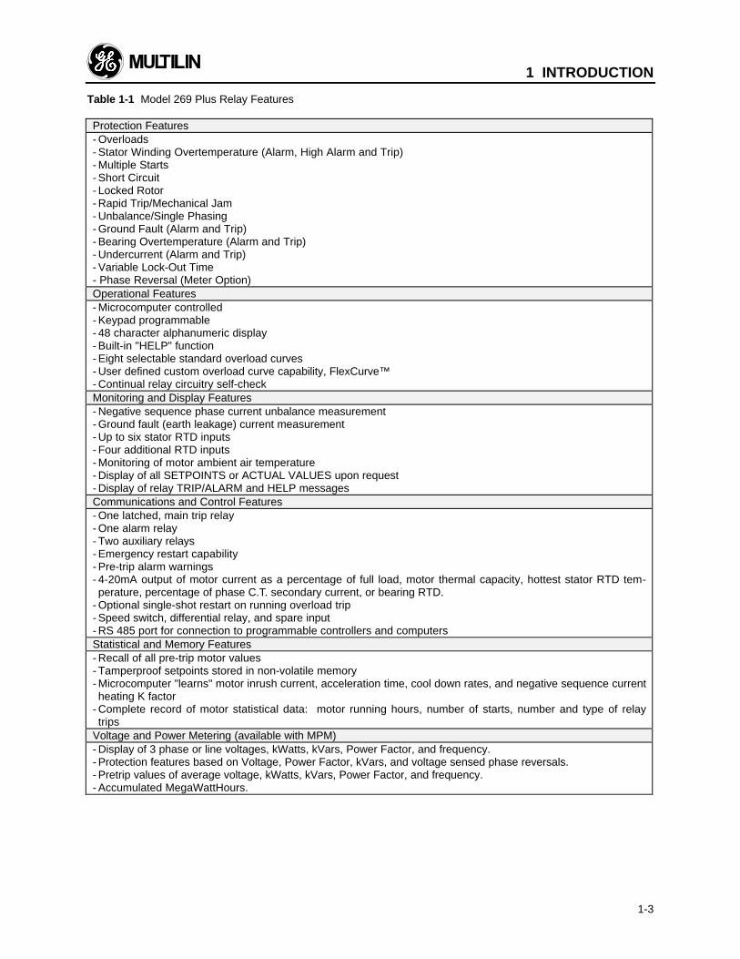
Table 1-1 Model 269 Plus Relay Features
Protection Features- Overloads- Stator Winding Overtemperature (Alarm, High Alarm and Trip)- Multiple Starts- Short Circuit- Locked Rotor- Rapid Trip/Mechanical Jam- Unbalance/Single Phasing- Ground Fault (Alarm and Trip)- Bearing Overtemperature (Alarm and Trip)- Undercurrent (Alarm and Trip)- Variable Lock-Out Time- Phase Reversal (Meter Option)Operational Features- Microcomputer controlled- Keypad programmable- 48 character alphanumeric display- Built-in "HELP" function- Eight selectable standard overload curves- User defined custom overload curve capability, FlexCurve™- Continual relay circuitry self-checkMonitoring and Display Features- Negative sequence phase current unbalance measurement- Ground fault (earth leakage) current measurement- Up to six stator RTD inputs- Four additional RTD inputs- Monitoring of motor ambient air temperature- Display of all SETPOINTS or ACTUAL VALUES upon request- Display of relay TRIP/ALARM and HELP messagesCommunications and Control Features- One latched, main trip relay- One alarm relay- Two auxiliary relays- Emergency restart capability- Pre-trip alarm warnings- 4-20mA output of motor current as a percentage of full load, motor thermal capacity, hottest stator RTD tem-perature, percentage of phase C.T. secondary current, or bearing RTD.
- Optional single-shot restart on running overload trip- Speed switch, differential relay, and spare input- RS 485 port for connection to programmable controllers and computersStatistical and Memory Features- Recall of all pre-trip motor values- Tamperproof setpoints stored in non-volatile memory- Microcomputer "learns" motor inrush current, acceleration time, cool down rates, and negative sequence currentheating K factor
- Complete record of motor statistical data: motor running hours, number of starts, number and type of relaytrips
Voltage and Power Metering (available with MPM)- Display of 3 phase or line voltages, kWatts, kVars, Power Factor, and frequency.- Protection features based on Voltage, Power Factor, kVars, and voltage sensed phase reversals.- Pretrip values of average voltage, kWatts, kVars, Power Factor, and frequency.- Accumulated MegaWattHours.
1 INTRODUCTION
1-4
1.3 Typical Applications
The many features of the 269 Plus make it an idealchoice for a wide range of motor protection applica-tions. Versatile features and controls allow the relay toprotect associated mechanical equipment as well asthe motor. The 269 Plus should be considered for thefollowing and other typical uses:
1. Protection of motors and equipment from operatorabuse.
2. Protection of personnel from shock hazards due towinding shorts or earth leakage current frommoisture.
3. Protection of gears, pumps, fans, saw mills, cut-ters, and compressors from mechanical jam.
4. Protection for loss of suction for pumps or loss ofair flow for fans using the undercurrent feature.
5. Protection of motor and load bearings from exces-sive heat buildup due to mechanical wear.
6. Protection of motors operated in environments withvarying ambient temperatures.
7. Communication with programmable controllersand computers for integrated plant control.
8. Protection of high inertia, long acceleration drivesystems using a custom overload curve.
9. Statistical record-keeping for effective maintenanceprograms.
10. Complete protection, allowing maximum motorutilization with minimum downtime, for all a.c.motors.
1 INTRODUCTION
1-5
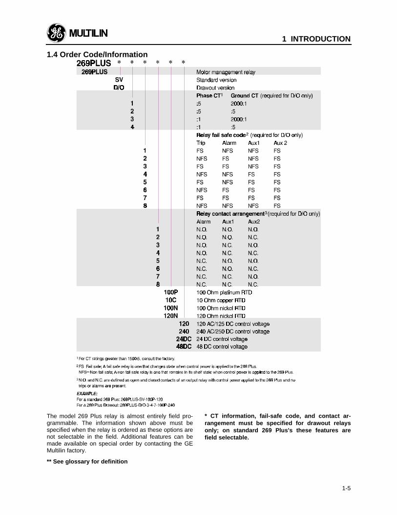
The model 269 Plus relay is almost entirely field pro-grammable. The information shown above must bespecified when the relay is ordered as these options arenot selectable in the field. Additional features can bemade available on special order by contacting the GEMultilin factory.
** See glossary for definition
* CT information, fail-safe code, and contact ar-rangement must be specified for drawout relaysonly; on standard 269 Plus's these features arefield selectable.
1.4 Order Code/Information
1 INTRODUCTION
1-6
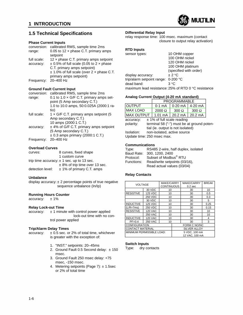
1.5 Technical Specifications
Phase Current Inputsconversion: calibrated RMS, sample time 2msrange: 0.05 to 12 × phase C.T. primary amps
setpointfull scale: 12 × phase C.T. primary amps setpointaccuracy: ± 0.5% of full scale (0.05 to 2 × phase
C.T. primary amps setpoint)± 1.0% of full scale (over 2 × phase C.T.primary amps setpoint)
Frequency: 20–400 Hz
Ground Fault Current Inputconversion: calibrated RMS, sample time 2msrange: 0.1 to 1.0 × G/F C.T. primary amps set-
point (5 Amp secondary C.T.)1.0 to 10.0 amps, 50:0.025A (2000:1 ra-tio)
full scale: 1 × G/F C.T. primary amps setpoint (5Amp secondary C.T.)10 amps (2000:1 C.T.)
accuracy: ± 4% of G/F C.T. primary amps setpoint(5 Amp secondary C.T.)± 0.3 amps primary (2000:1 C.T.)
Frequency: 20–400 Hz
Overload Curvescurves: 8 curves, fixed shape
1 custom curvetrip time accuracy: ± 1 sec. up to 13 sec.
± 8% of trip time over 13 sec.detection level: ± 1% of primary C.T. amps
Unbalancedisplay accuracy: ± 2 percentage points of true negative
sequence unbalance (In/Ip)
Running Hours Counteraccuracy: ± 1%
Relay Lock-out Timeaccuracy: ± 1 minute with control power applied
lock-out time with no con-trol power applied
Trip/Alarm Delay Timesaccuracy: ± 0.5 sec. or 2% of total time, whichever
is greater with the exception of:
1. "INST." setpoints: 20–45ms2. Ground Fault 0.5 Second delay: ± 150
msec.3. Ground Fault 250 msec delay: +75
msec, -150 msec.4. Metering setpoints (Page 7): ± 1.5sec
or 2% of total time
Differential Relay Inputrelay response time: 100 msec. maximum (contact
closure to output relay activation)
RTD Inputssensor types: 10 OHM copper
100 OHM nickel120 OHM nickel100 OHM platinum(specified with order)
display accuracy: ± 2 °Ctrip/alarm setpoint range: 0-200 °Cdead band: 3 °Cmaximum lead resistance: 25% of RTD 0 °C resistance
Analog Current Output (4-20 mA standard)PROGRAMMABLE
OUTPUT 0-1 mA 0-20 mA 4-20 mAMAX LOAD 2000 Ω 300 Ω 300 ΩMAX OUTPUT 1.01 mA 20.2 mA 20.2 mAaccuracy: ± 1% of full scale readingpolarity: terminal 58 ("-") must be at ground poten-
tial (ie. output is not isolated)Isolation: non-isolated, active sourceUpdate time: 250 msec max.
CommunicationsType: RS485 2-wire, half duplex, isolatedBaud Rate: 300, 1200, 2400Protocol: Subset of Modbus® RTUFunctions: Read/write setpoints (03/16),
Read actual values (03/04)
Relay Contacts
VOLTAGEMAKE/CARRYCONTINUOUS
MAKE/CARRY0.2 sec
BREAK
30 VDC 10 30 10RESISTIVE 125 VDC 10 30 0.5
250 VDC 10 30 0.330 VDC 10 30 5
INDUCTIVE 125 VDC 10 30 0.25(L/R=7ms) 250 VDC 10 30 0.15RESISTIVE 120 VAC 10 30 10
250 VAC 10 30 10INDUCTIVE 120 VAC 10 30 4
PF=0.4 250 VAC 10 30 3CONFIGURATION FORM C NO/NCCONTACT MATERIAL SILVER ALLOYMINIMUM PERMISSIBLE LOAD: 5 VDC, 100 mA
12 VAC, 100 mA
Switch InputsType: dry contacts
1 INTRODUCTION
1-7
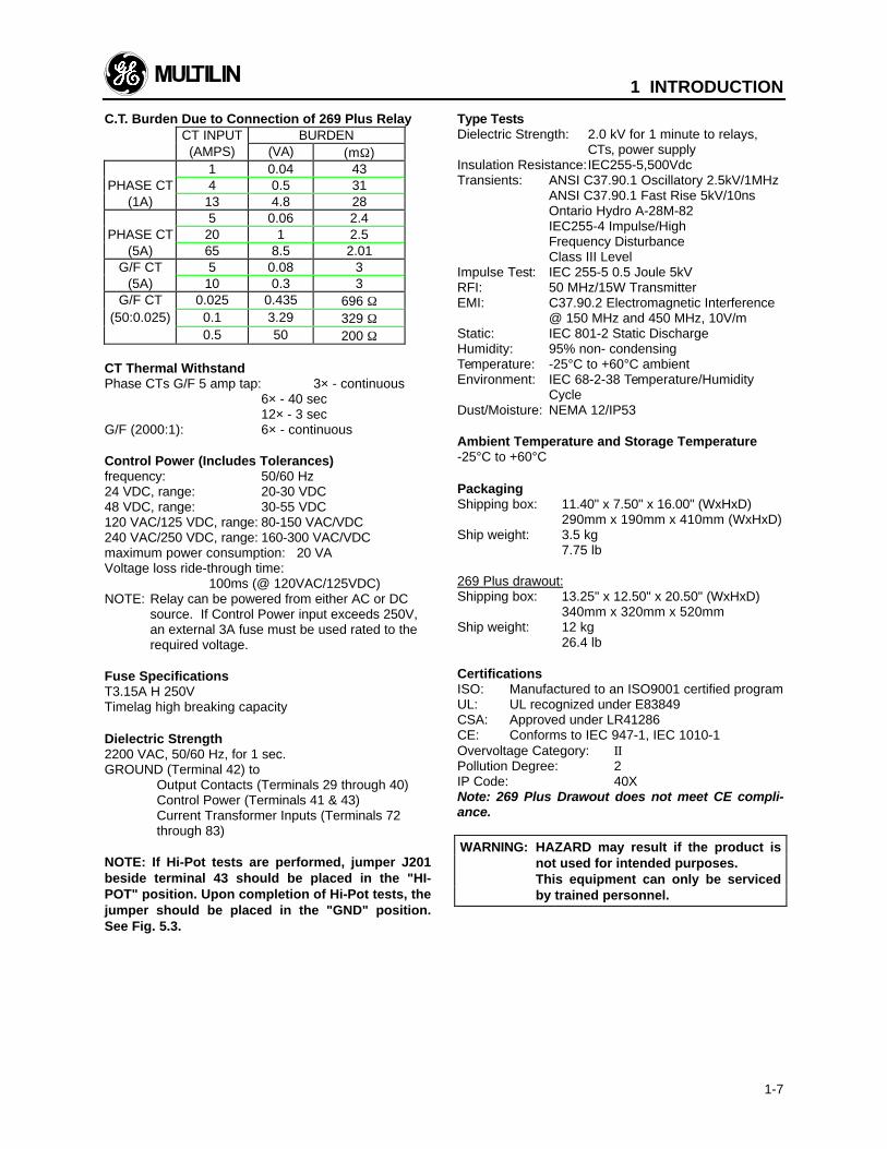
C.T. Burden Due to Connection of 269 Plus RelayCT INPUT BURDEN(AMPS) (VA) (mΩ)
1 0.04 43PHASE CT 4 0.5 31
(1A) 13 4.8 285 0.06 2.4
PHASE CT 20 1 2.5(5A) 65 8.5 2.01
G/F CT 5 0.08 3(5A) 10 0.3 3
G/F CT 0.025 0.435 696 Ω(50:0.025) 0.1 3.29 329 Ω
0.5 50 200 Ω
CT Thermal WithstandPhase CTs G/F 5 amp tap: 3× - continuous
6× - 40 sec12× - 3 sec
G/F (2000:1): 6× - continuous
Control Power (Includes Tolerances)frequency: 50/60 Hz24 VDC, range: 20-30 VDC48 VDC, range: 30-55 VDC120 VAC/125 VDC, range: 80-150 VAC/VDC240 VAC/250 VDC, range: 160-300 VAC/VDCmaximum power consumption: 20 VAVoltage loss ride-through time:
100ms (@ 120VAC/125VDC)NOTE: Relay can be powered from either AC or DC
source. If Control Power input exceeds 250V,an external 3A fuse must be used rated to therequired voltage.
Fuse SpecificationsT3.15A H 250VTimelag high breaking capacity
Dielectric Strength2200 VAC, 50/60 Hz, for 1 sec.GROUND (Terminal 42) to
Output Contacts (Terminals 29 through 40)Control Power (Terminals 41 & 43)Current Transformer Inputs (Terminals 72through 83)
NOTE: If Hi-Pot tests are performed, jumper J201beside terminal 43 should be placed in the "HI-POT" position. Upon completion of Hi-Pot tests, thejumper should be placed in the "GND" position.See Fig. 5.3.
Type TestsDielectric Strength: 2.0 kV for 1 minute to relays,
CTs, power supplyInsulation Resistance:IEC255-5,500VdcTransients: ANSI C37.90.1 Oscillatory 2.5kV/1MHz
ANSI C37.90.1 Fast Rise 5kV/10nsOntario Hydro A-28M-82IEC255-4 Impulse/HighFrequency DisturbanceClass III Level
Impulse Test: IEC 255-5 0.5 Joule 5kVRFI: 50 MHz/15W TransmitterEMI: C37.90.2 Electromagnetic Interference
@ 150 MHz and 450 MHz, 10V/mStatic: IEC 801-2 Static DischargeHumidity: 95% non- condensingTemperature: -25°C to +60°C ambientEnvironment: IEC 68-2-38 Temperature/Humidity
CycleDust/Moisture: NEMA 12/IP53
Ambient Temperature and Storage Temperature-25°C to +60°C
PackagingShipping box: 11.40" x 7.50" x 16.00" (WxHxD)
290mm x 190mm x 410mm (WxHxD)Ship weight: 3.5 kg
7.75 lb
269 Plus drawout:Shipping box: 13.25" x 12.50" x 20.50" (WxHxD)
340mm x 320mm x 520mmShip weight: 12 kg
26.4 lb
CertificationsISO: Manufactured to an ISO9001 certified programUL: UL recognized under E83849CSA: Approved under LR41286CE: Conforms to IEC 947-1, IEC 1010-1Overvoltage Category: IIPollution Degree: 2IP Code: 40XNote: 269 Plus Drawout does not meet CE compli-ance.
WARNING: HAZARD may result if the product isnot used for intended purposes.This equipment can only be servicedby trained personnel.
1 INTRODUCTION
1-8
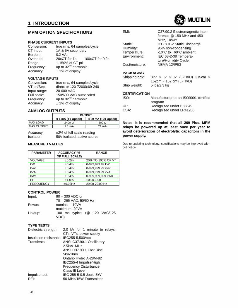
MPM OPTION SPECIFICATIONS
PHASE CURRENT INPUTSConversion: true rms, 64 samples/cycleCT input: 1A & 5A secondaryBurden: 0.2 VAOverload: 20xCT for 1s, 100xCT for 0.2sRange: 1-150% of CT priFrequency: up to 32nd harmonicAccuracy: ± 1% of display
VOLTAGE INPUTSConversion: true rms, 64 samples/cycleVT pri/Sec: direct or 120-72000:69-240Input range: 20-600 VACFull scale: 150/600 VAC autoscaledFrequency: up to 32nd harmonicAccuracy: ± 1% of display
ANALOG OUTPUTSOUTPUT
0-1 mA (T1 Option) 4-20 mA (T20 Option)MAX LOAD 2400 Ω 600 ΩMAX OUTPUT 1.1 mA 21 mA
Accuracy: ±2% of full scale readingIsolation: 50V isolated, active source
MEASURED VALUES
PARAMETER ACCURACY (%OF FULL SCALE)
RANGE
VOLTAGE ±0.2% 20% TO 100% OF VTkW ±0.4% 0-999,999.99 kWkvar ±0.4% 0-999,999.99 kvarkVA ±0.4% 0-999,999.99 kVAkWh ±0.4% 0-999,999,999 kWhPF ±1.0% ±0.00-1.00FREQUENCY ±0.02Hz 20.00-70.00 Hz
CONTROL POWERInput: 90 – 300 VDC or
70 – 265 VAC, 50/60 HzPower: nominal 10VA
maximum 20VAHoldup: 100 ms typical (@ 120 VAC/125
VDC)
TYPE TESTSDielectric strength: 2.0 kV for 1 minute to relays,
CTs, VTs, power supplyInsulation resistance: IEC255-5,500VdcTransients: ANSI C37.90.1 Oscillatory
2.5kV/1MHzANSI C37.90.1 Fast Rise5kV/10nsOntario Hydro A-28M-82IEC255-4 Impulse/HighFrequency DisturbanceClass III Level
Impulse test: IEC 255-5 0.5 Joule 5kVRFI: 50 MHz/15W Transmitter
EMI: C37.90.2 Electromagnetic Inter-ference @ 150 MHz and 450MHz, 10V/m
Static: IEC 801-2 Static DischargeHumidity: 95% non-condensingTemperature: -10°C to +60°C ambientEnvironment: IEC 68-2-38 Tempera-
ture/Humidity CycleDust/moisture: NEMA 12/IP53
PACKAGINGShipping box: 8½" × 6" × 6" (L×H×D) 215cm ×
152cm × 152 cm (L×H×D)Ship weight: 5 lbs/2.3 kg
CERTIFICATIONISO: Manufactured to an ISO9001 certified
programUL: Recognized under E83849CSA: Recognized under LR41286
Note: It is recommended that all 269 Plus, MPMrelays be powered up at least once per year toavoid deterioration of electrolytic capacitors in thepower supply.
Due to updating technology, specifications may be improved with-out notice.
2 INSTALLATION
2-1
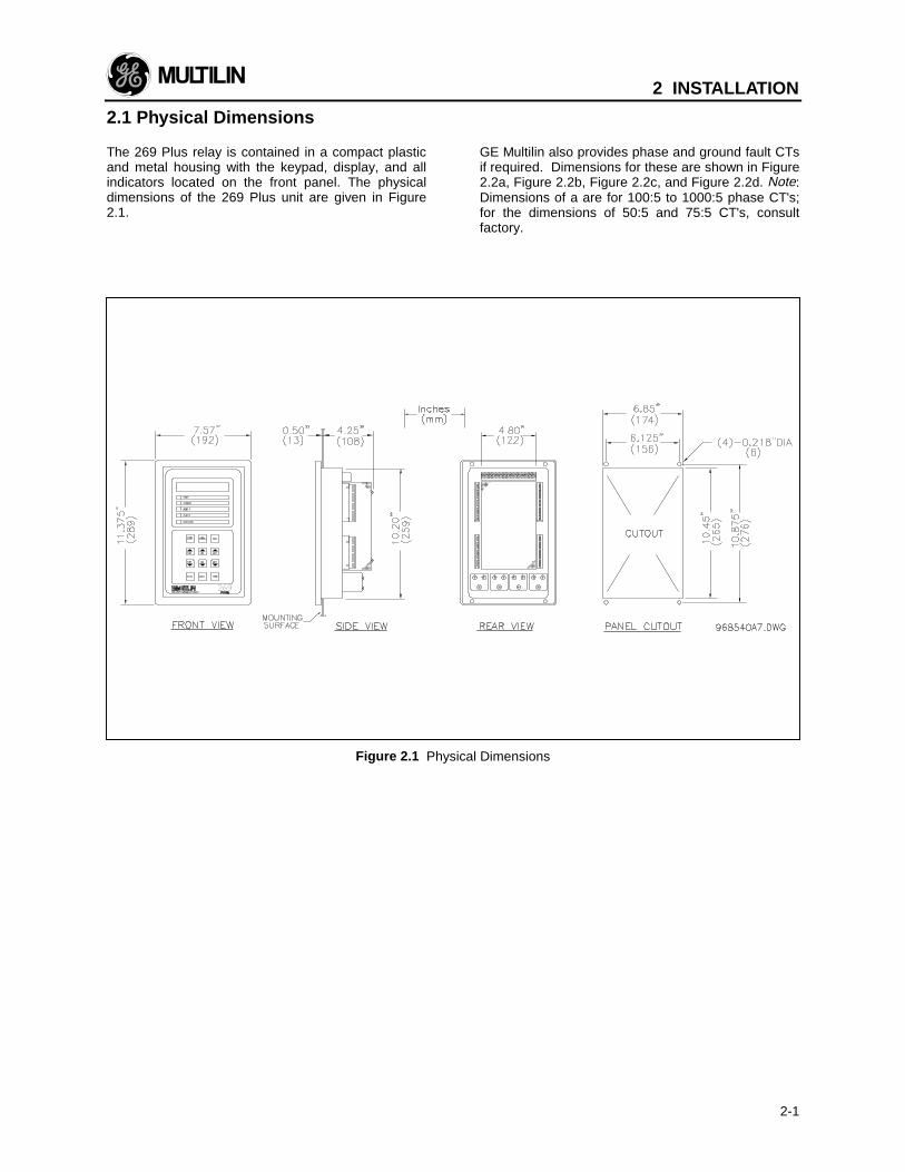
2.1 Physical Dimensions
The 269 Plus relay is contained in a compact plasticand metal housing with the keypad, display, and allindicators located on the front panel. The physicaldimensions of the 269 Plus unit are given in Figure2.1.
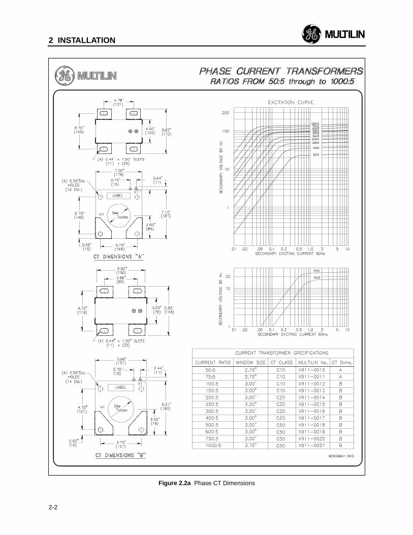
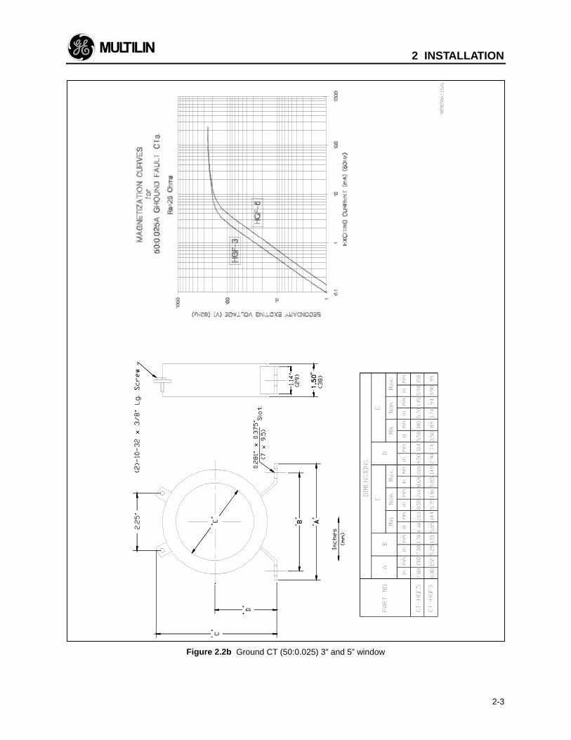
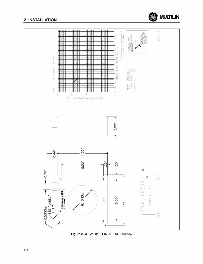
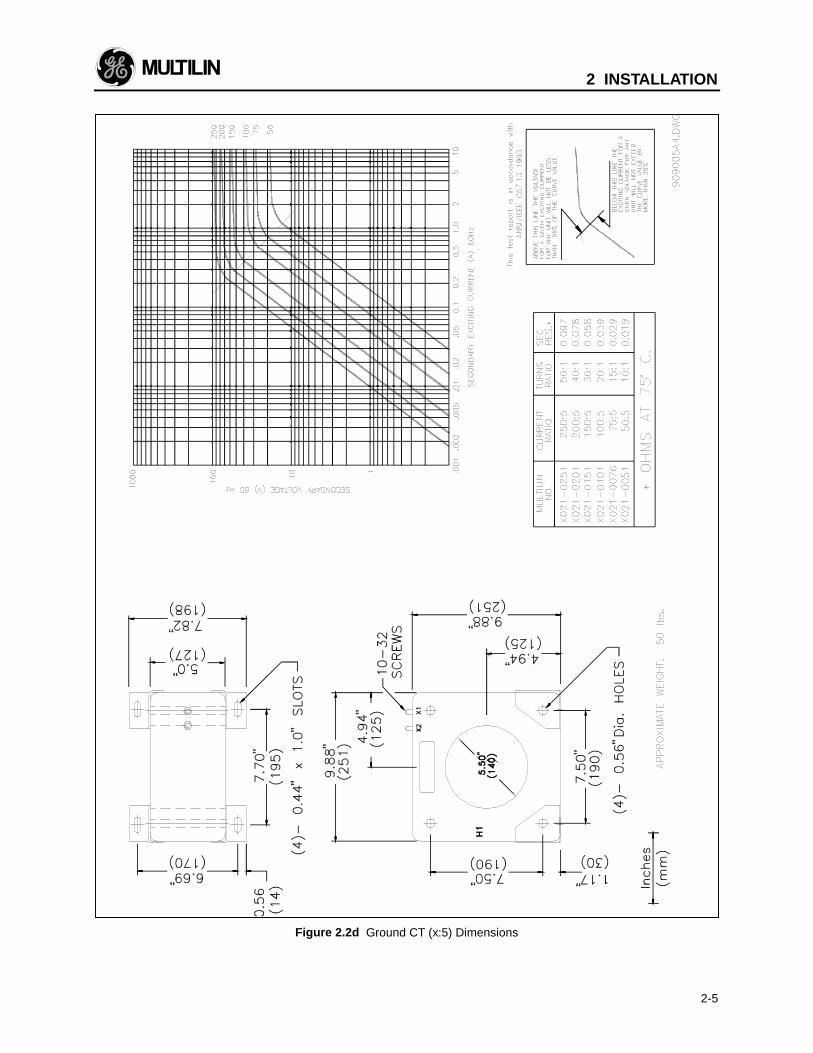
GE Multilin also provides phase and ground fault CTsif required. Dimensions for these are shown in Figure2.2a, Figure 2.2b, Figure 2.2c, and Figure 2.2d. Note:Dimensions of a are for 100:5 to 1000:5 phase CT's;for the dimensions of 50:5 and 75:5 CT's, consultfactory.
Figure 2.1 Physical Dimensions
2 INSTALLATION
2-2
Figure 2.2a Phase CT Dimensions
2 INSTALLATION
2-3
Figure 2.2b Ground CT (50:0.025) 3” and 5” window
2 INSTALLATION
2-4
Figure 2.2c Ground CT (50:0.025) 8” window
2 INSTALLATION
2-5
Figure 2.2d Ground CT (x:5) Dimensions
2 INSTALLATION
2-6
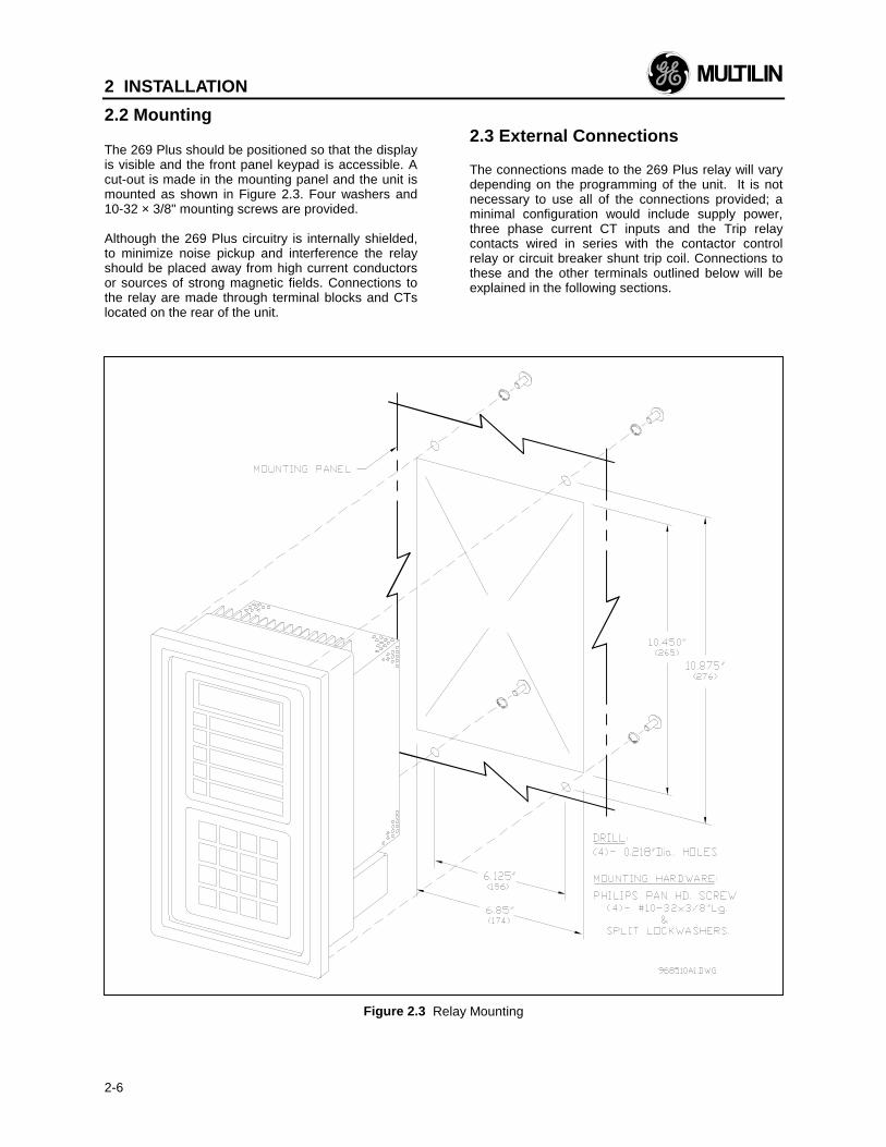
2.2 Mounting
The 269 Plus should be positioned so that the displayis visible and the front panel keypad is accessible. Acut-out is made in the mounting panel and the unit ismounted as shown in Figure 2.3. Four washers and10-32 × 3/8" mounting screws are provided.
Although the 269 Plus circuitry is internally shielded,to minimize noise pickup and interference the relayshould be placed away from high current conductorsor sources of strong magnetic fields. Connections tothe relay are made through terminal blocks and CTslocated on the rear of the unit.
2.3 External Connections
The connections made to the 269 Plus relay will varydepending on the programming of the unit. It is notnecessary to use all of the connections provided; aminimal configuration would include supply power,three phase current CT inputs and the Trip relaycontacts wired in series with the contactor controlrelay or circuit breaker shunt trip coil. Connections tothese and the other terminals outlined below will beexplained in the following sections.
Figure 2.3 Relay Mounting
2 INSTALLATION
2-7
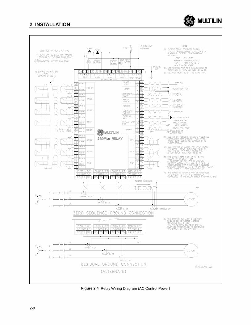
Figure 2.4, Figure 2.6, and Figure 2.7 show typicalconnections to the 269 Plus relay.
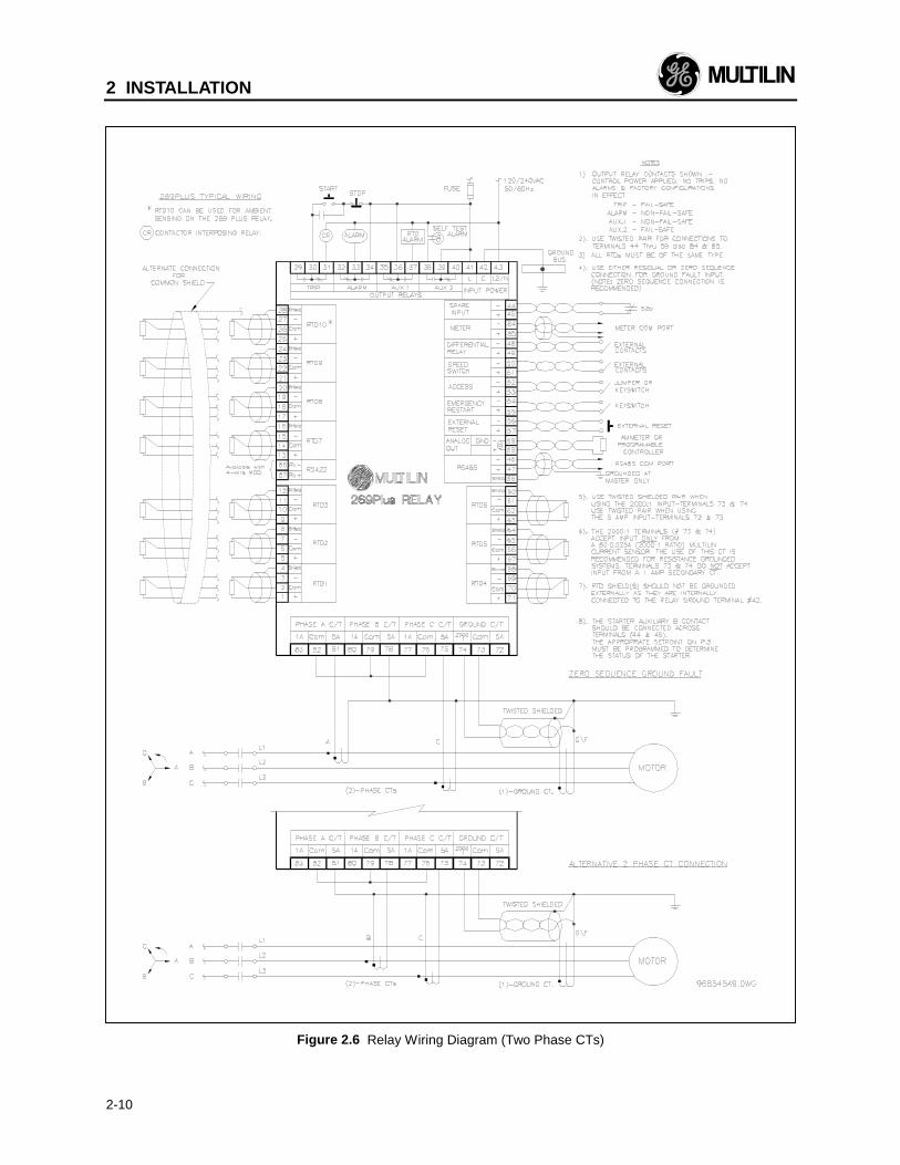
NOTE: The rear of the 269 Plus relay shows outputrelay contacts in their power down state. Figure 2.4,Figure 2.6, and Figure 2.7 show output relay contactswith power applied, no trips or alarms, FactoryConfigurations, i.e. TRIP - fail-safe, ALARM - non-fail-safe, AUX.1 - non-fail-safe, AUX.2 - fail-safe). SeeFigure 2.5 for a complete list of all possible outputrelay contact states. See SETPOINTS page 5 for adescription of the RELAY FAILSAFE CODE.
Table 2-1 269 Plus External Connections
Inputs-Supply Power L(+), G, N(–) - universal AC/DCsupply-Phase CTs-Ground Fault CTs (core balance CT)-6 Stator RTDs-4 additional RTDs-Emergency Restart keyswitch-External Reset pushbutton-Programming Access jumper or keyswitch-Speed Switch input-Differential Relay input-Spare input-Meter Communication PortOutputs-4 Sets of Relay Contacts (NO/NC)-Programmable Analog Current Output Terminals-RS 485 Serial Communication Port
WARNING: HAZARD may result if the product isnot used for intended purposes. Thisequipment can only be serviced bytrained personnel.
2 INSTALLATION
2-8
Figure 2.4 Relay Wiring Diagram (AC Control Power)
2 INSTALLATION
2-9
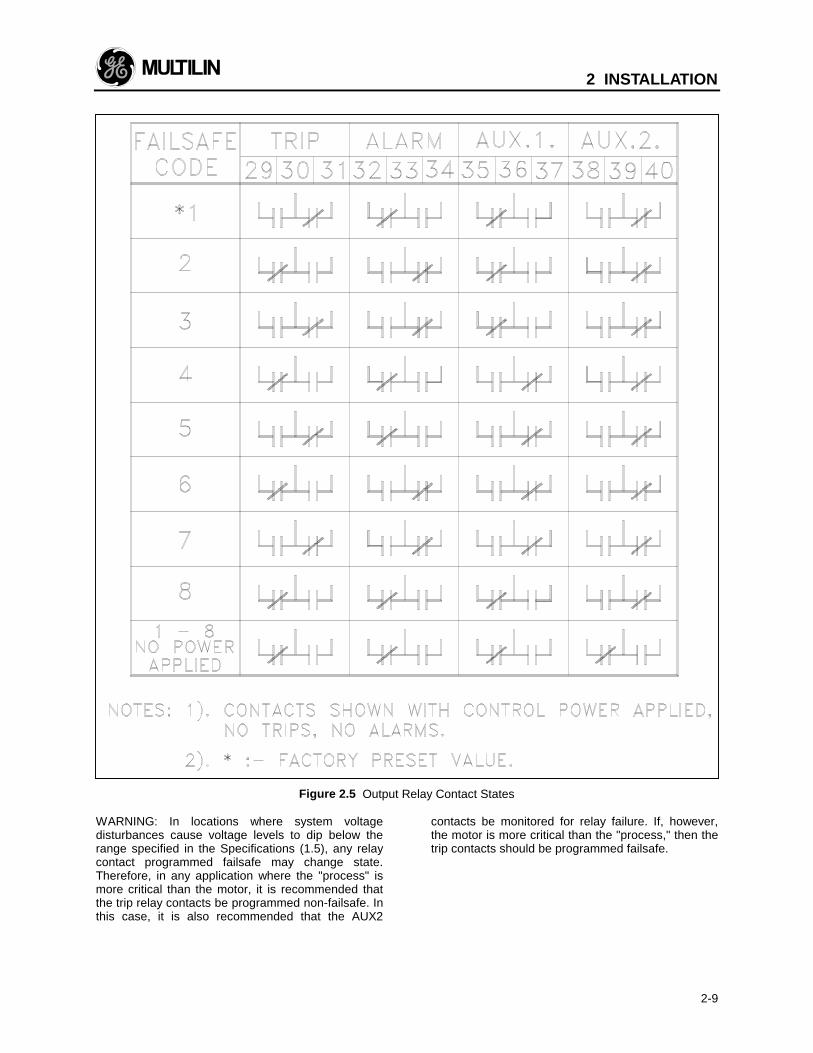
Figure 2.5 Output Relay Contact States
WARNING: In locations where system voltagedisturbances cause voltage levels to dip below therange specified in the Specifications (1.5), any relaycontact programmed failsafe may change state.Therefore, in any application where the "process" ismore critical than the motor, it is recommended thatthe trip relay contacts be programmed non-failsafe. Inthis case, it is also recommended that the AUX2
contacts be monitored for relay failure. If, however,the motor is more critical than the "process," then thetrip contacts should be programmed failsafe.
2 INSTALLATION
2-10
Figure 2.6 Relay Wiring Diagram (Two Phase CTs)
2 INSTALLATION
2-11
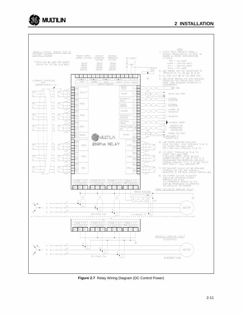
Figure 2.7 Relay Wiring Diagram (DC Control Power)
2 INSTALLATION
2-12
2.4 Control Power
The relay is powered on using any one of fourdifferent switching power supplies: 120-125VAC/VDC, 240-250 VAC/VDC, 48 VDC, or 24 VDC.The first two versions have been designed to workwith either AC or DC control power. Maximum powerconsumption for the unit is 20 VA.
The 269 Plus will operate properly over a wide rangeof supply voltages typically found in industrialenvironments (see control power specifications insection 1.5). When the supply voltage drops belowthe minimum, the output relays will return to theirpower down states but all setpoints and statisticaldata will remain stored in the relay memory. Motorlock-out time will be adhered to with or without controlpower applied. If control power is removed, the relaykeeps track of the Motor Lockout time for up to anhour.
Control power must be applied to the 269 Plus relay,and the relay programmed, before the motor isenergized. Power is applied at terminals 41, 42, and43 which are terminal blocks having #6 screws.
Note: Chassis ground terminal 42 must beconnected directly to the dedicated cubicleground bus to prevent transients from damagingthe 269 Plus resulting from changes in groundpotential within the cubicle. Terminal 42 must begrounded for both AC and DC units for thisreason.
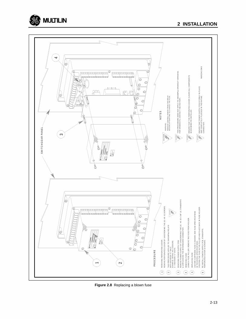
Verify from the product identification label on the backof the relay that the control voltage matches theintended application. Connect the control voltageinput to a stable source of supply for reliableoperation. A 3.15A, slow blow mini fuse (see FuseSpecifications in Technical Specifications) isaccessible from the back of the 269 Plus by removingthe perforated cover. See Figure 2.8 for details onreplacing the fuse. Using #10 gauge wire or groundbraid, connect terminal 42 to a solid ground which istypically the copper ground bus in the switchgear.Extensive filtering and transient protection is built intothe 269 Plus to ensure reliable operation under harshindustrial operating environments. Transient energymust be conducted back to the source through filterground. The filter ground is separated from the safetyground terminal 42 at jumper J201 on the back of therelay to allow dielectric testing of a switchgear with a269 Plus wired up. Jumper J201 must be removedduring dielectric testing. It must be put back in placeonce the dielectric testing is done.
When properly installed, the 269 Plus will meet theinterference immunity requirements of IEC 1000-4-3/EN61000-4-3; EN 61000-4-6. It also meets theemission requirements of IEC CISPR11/EN55011and EN50082-2.
2.5 Phase CT Inputs
One CT for each of the three motor phases isrequired to input a current into the relay proportionalto the motor phase current. The phase sequencemust be as shown in Figure 2.4 and Figure 2.7. TheCTs used can have either a 1 amp or 5 ampsecondary and should be chosen so that the motorfull load current is between 75 and 95 percent of therated CT primary amps. The CT ratio should thus beof the form n:1 or n:5 where n is between 20 and1500. The ratio of the CT used must be programmedinto the 269 Plus (see section 3.7).
The CT connections to the relay are made betweenthe ":1" and "COM" terminals for 1 amp CTs orbetween the ":5" and "COM" terminals for CTs with a5 amp secondary.
The connections to the 269 Plus internal phase CTsare made directly via #10 screws.
CTs should be selected to be capable of supplyingthe required current to the total secondary load whichincludes the 269 Plus relay burden of 0.1 VA at ratedsecondary current and the connection wiring burden.The CT must not saturate under maximum currentconditions which can be up to 8 times motor full loadduring starting or up to 20 times during a short circuit.Only CTs rated for protective relaying should be usedsince metering CTs are usually not rated to provideenough current during faults. Typical CT ratings are:
CSA (Canada): Class10L100 10=accuracy,L=protection,100=capacity, higher isbetter
ANSI (USA): Class C 100 B4 C or T=protection,100=capacity, higher isbetter, B4=accuracy
IEC (Europe): 20 VA Class 5P20 P=protection,20VA=capacity, higher isbetter
Refer to Appendix H for details on CT withstand, CTsize and saturation, as well as the safe use of 600Vclass window type CTs on a 5 kV circuit.
2 INSTALLATION
2-13
Figure 2.8 Replacing a blown fuse
4
RE
MO
VE
PE
RF
OR
AT
ED
CO
VE
R B
Y U
NS
CR
EW
ING
TH
E (
4)-
#8
-3
2 S
CR
EW
S.
RE
MO
VE
PO
WE
R S
UP
PLY
BY
UN
SC
RE
WIN
G T
HE
(4)
- #
8 -
32 x
3/8
" L
G.
STA
ND
OF
FS
RE
MO
VIN
G P
ER
FO
RA
TE
D C
OV
ER
:1
& U
NP
LU
GG
ING
TH
E I
NT
ER
BO
AR
D C
ON
NE
CT
OR
.
CA
UT
ION
RE
MO
VE
CO
NT
RO
L P
OW
ER
FR
OM
TH
E R
EL
AY
BE
FO
RE
AT
TE
MP
TIN
G T
O C
HA
NG
E T
HE
FU
SE
.
WA
RN
ING
:
RE
MO
VIN
G P
OW
ER
SU
PP
LY P
CB
:
CA
UT
ION
EN
SU
RE
TH
AT
TH
E P
ER
FO
RA
TE
D C
OV
ER
CL
EA
RS
ALL
CO
MP
ON
EN
TS
WH
EN
BE
ING
RE
-IN
STA
LLE
D.
FO
R D
RA
WO
UT
S,
CO
NTA
CT
TH
E F
AC
TO
RY
. T
HIS
PR
OC
ED
UR
E D
OE
S N
OT
AP
PLY
TO
269
/26
9Plu
s D
RA
WO
UT
VE
RS
ION
S.
CA
UT
ION
TH
IS P
RO
CE
DU
RE
AP
PLI
ES
TO
26
9/2
69
Plu
s R
EL
AY
SW
ITH
RE
VIS
ION
"C
" O
NLY
.
C =
RE
VIS
ION
"C
" U
NIT
S.
EX
AM
PLE
: S
ER
IAL
NO
. C
52
613
92
1 2
2C
AU
TIO
N
NO
TE
S
PR
OC
ED
UR
E
RE
MO
VIN
G F
US
E:
RE
PL
AC
ING
FU
SE
:
4
IN T
EC
HN
ICA
L S
PE
CIF
ICA
TIO
NS
.U
SE
MIN
I CA
RT
RID
GE
FU
SE
3.1
5A
/25
0V
. S
EE
FU
SE
SP
EC
IFIC
AT
ION
S
US
ING
A F
US
E P
UL
LE
R, R
EM
OV
E T
HE
FU
SE
FR
OM
HO
LD
ER
.
PE
RF
OR
ATE
D C
OV
ER
& S
CR
EW
S.
RE
-IN
STA
LL
PO
WE
R S
UP
PLY
PC
B,
STA
ND
OF
FS
, 6
3 AN
D C
OM
PLE
TE
LY P
LU
GG
ED
IN
TH
E M
AT
ING
96
80
23A
2.D
WG
EN
SU
RE
TH
AT
PO
WE
R S
UP
PLY
PC
B I
S F
IRM
LY IN
PL
AC
EC
AU
TIO
N
CO
NN
EC
TO
R.
SW
ITC
HG
EA
R P
AN
EL
5
PO
SIT
ION
TH
E F
US
E I
N T
HE
PU
LL
ER
AN
D P
LA
CE
BA
CK
IN
FU
SE
HO
LD
ER
.
3
2 INSTALLATION
2-14
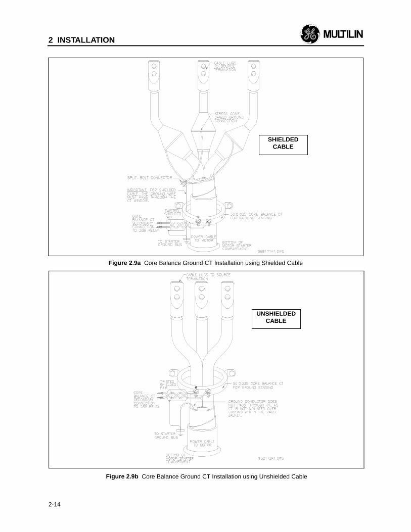
Figure 2.9a Core Balance Ground CT Installation using Shielded Cable
Figure 2.9b Core Balance Ground CT Installation using Unshielded Cable
SHIELDEDCABLE
UNSHIELDEDCABLE
2 INSTALLATION
2-15
2.6 Ground CT Input
All current carrying conductors must pass through aseparate ground fault CT in order for the ground faultfunction to operate correctly. If the CT is placed overa shielded cable, capacitive coupling of phase currentinto the cable shield during motor starts may bedetected as ground current unless the shield wire isalso passed through the CT window; see Figure 2.9a.If a safety ground is used it should pass outside theCT window; see Figure 2.9b.
The connections to the 269 Plus internal ground CTare made directly via #10 screws. The ground CT isconnected to terminals 73 and 72 for a 5 ampsecondary CTs, or to terminals 73 and 74 for a GEMultilin 50:0.025A (2000:1 ratio) CTs, as shown inFigure 2.4, Figure 2.5, and Figure 2.7. The polarity ofthe ground CT connection is not important. It isrecommended that the two CT leads be twistedtogether to minimize noise pickup . If a 50:0.025A(2000:1 ratio) ground CT is used, the secondaryoutput will be a low-level signal which allows forsensitive ground fault detection.
NOTE: The GE Multilin 2000:1 CT is actually a50:0.025A CT recommended for resistancegrounded systems where sensitive ground faultdetection is required. If higher levels are to bedetected, a 5 Amp secondary CT should be used.
For a solidly grounded system where higher groundfault currents will flow, a 5 amp secondary CT with aprimary between 20 and 1500 A may be used tosurround all phase conductors. The phase CTs mayalso be residually connected to provide groundsensing levels as low as 10% of the phase CTprimary rating. For example, 100:5 CTs connected inthe residual configuration can sense ground currentsas low as 10 amps (primary) without requiring aseparate ground CT. See Figure 2.4 and Figure 2.7.This saves the expense of an extra CT, however 3phase CTs are required. If this connection is used ona high resistance grounded system verify that theground fault alarm and trip current setpoints arebelow the maximum ground current that can flow dueto limiting by the system ground resistance. Sensinglevels below 10% of the phase CT primary rating arenot recommended for reliable operation.
When the phase CTs are connected residually, thesecondaries must be connected in such a way toallow the 269 Plus to sense any ground current thatmight be flowing. To correctly display ground currentand trip or alarm on ground fault, the connection tothe 269 Plus must be made at terminals 72 and 73 asshown in Figure 2.4 and Figure 2.7. These terminalsare designed to accept input from a 5A secondaryCT. The 269 Plus must also be programmed for a 5Asecondary ground CT with the primary being equal tothe phase CT primary. This is done in SETPOINTS,
page 1.
2.7 Trip Relay Contacts
The main control relay or shunt trip coil of the motorstarter or circuit breaker should be connected to theTrip relay contacts of the 269 Plus. These contactsare available as normally open (NO), normally closed(NC), and can switch up to 10 amps at either 250VAC or 30 VDC with a resistive load. Silver cadmiumoxide contacts are used because of their ability tohandle high inrush currents on inductive loads.Contact GE Multilin if these contacts are to be usedfor carrying low currents since they are notrecommended for use below 0.1 amps. Connection tothe motor contactor or breaker is shown in Figure 2.4,Figure 2.5, and Figure 2.7.
The Trip output relay will remain latched after a trip.This means that once this relay has been activated itwill remain in the active state until the 269 Plus ismanually reset. The Trip relay contacts may be resetby pressing the RESET key (see section 3.1) if motorconditions allow, or by using the Emergency Restartfeature (see section 2.12), or the External Resetterminals, or by remote communications via theRS485 port.
The Trip relay may be programmed to be fail-safe ornon-fail-safe. When in the fail-safe mode, relayactivation or a loss of power condition will cause therelay contacts to go to their power down state. Thus,in order to cause a trip on loss of power to the 269Plus, output relays should be programmed as fail-safe.
The Trip relay cannot be reset if a lock-out is in effect.Lock-out time will be adhered to regardless ofwhether control power is present or not. A maximumof one hour lockout time is observed if control poweris not present.
The Trip relay can be programmed to activate on anycombination of the following trip conditions: overload,stator RTD overtemperature, rapid trip, unbalance,ground fault, short circuit, RTD overtemperature,acceleration time, number of starts per hour, singlephase, speed switch closure on start, differential relayclosure, spare input closure, and start inhibit (seesection 3.4 for factory preset configurations).
Connections to the Trip relay contacts are made via aterminal block which uses #6 screws.
NOTE: The rear of the 269 Plus relay shows outputrelay contacts in their power down state. Figure 2.4,Figure 2.6, and Figure 2.7 show output relay contactswith power applied, no trips or alarms, and FactoryConfigurations in effect (i.e. TRIP - fail-safe, ALARM -
2 INSTALLATION
2-16
non-fail-safe, AUX.1 - non-fail-safe, AUX.2 - fail-safe).See Figure 2.5 for a list of all possible contact states.
WARNING: In locations where system voltagedisturbances cause voltage levels to dip belowthe range specified in the Specifications (1.5), anyrelay contact programmed fail-safe may changestate. Therefore, in any application where the"process" is more critical than the motor, it isrecommended that the trip relay contacts beprogrammed non-failsafe. In this case, it is alsorecommended that the AUX2 contacts bemonitored for relay failure. If, however, the motoris more critical than the "process" then the tripcontacts should be programmed fail-safe.
2.8 Alarm Relay Contacts
These contacts are available as normally open (NO),normally closed (NC), with the same ratings as theTrip relay but can only be programmed to activatewhen alarm setpoint levels are reached. (On aDrawout version of the 269 Plus, only one set ofalarm contacts is available and the user must specifynormally open or normally closed and failsafe or non-failsafe when ordering). Thus these contacts may beused to signal a low-level fault condition prior tomotor shut-down.
Conditions which can be programmed to activate therelay are alarm levels for the following functions:immediate overload; mechanical jam; unbalance;undercurrent; ground fault; stator RTDovertemperature; high stator RTD overtemperature;RTD overtemperature; high RTD overtemperature;broken RTD; low temperature or shorted RTD; spareinput alarm; self-test alarm (see section 3.4 forfactory preset configurations). The relay can beconfigured as latched or unlatched and fail-safe ornon-fail-safe.
Connections to the Alarm relay contacts are made viaa terminal block which uses #6 screws.
NOTE: The rear of the 269 Plus relay shows outputrelay contacts in their power down state. Figure 2.4,Figure 2.6 and Figure 2.7 show output relay contactswith power applied, no trips or alarms, and FactoryConfigurations in effect (i.e. TRIP - fail-safe, ALARM -non-fail-safe, AUX.1 - non-fail-safe, AUX.2 - fail-safe).See Figure 2.5 for a list of all possible contact states.
2.9 Auxiliary Relay #1 Contacts
Auxiliary relay #1 is provided to give an extra set ofNO/NC contacts which operate independently of theother relay contacts. (On a Drawout version of the269 Plus, only one set of Aux.1 contacts is available
and the user must specify normally open or normallyclosed and failsafe or non-failsafe when ordering).This auxiliary relay has the same ratings as the Triprelay.
Auxiliary relay #1 can be configured as latched orunlatched and fail-safe or non-fail-safe. Theconditions that will activate this relay can be any tripor alarm indications (see section 3.4 for factory presetconfigurations).
These contacts may be used for alarm purposes or totrip devices other than the motor contactor. Forexample, the ground fault and short circuit functionsmay be directed to Auxiliary relay #1 to trip the maincircuit breaker rather than the motor starter.
Connections to the relay contacts are made via aterminal block which uses #6 screws.
NOTE: The rear of the 269 Plus relay shows outputrelay contacts in their power down state. Figure 2.4,Figure 2.6, and Figure 2.7 show output relay contactswith power applied, no trips or alarms, and FactoryConfigurations in effect (i.e. TRIP - fail-safe, ALARM -non-fail-safe, AUX.1 - non-fail-safe, AUX.2 - fail-safe).See Figure 2.5 for a list of all possible contact states.
2.10 Auxiliary Relay #2 Contacts
This relay provides another set of NO/NC contactswith the same ratings as the other relays. (On aDraw-out version of 269 Plus, only one set of Aux.2contacts is available and the user must specifynormally open or normally closed when ordering).This relay is different from the others in the fact that itis permanently programmed as latched and fail-safe.
This relay may be programmed to activate on anycombination of alarm conditions (see section 3.4 forfactory preset configurations). The featureassignment programming is thus the same as for theAlarm relay.
Connections to the relay contacts are made via aterminal block which uses #6 screws.
NOTE: The rear of the 269 Plus relay shows outputrelay contacts in their power down state. Figure 2.4,Figure 2.6, and Figure 2.7 show output relay contactswith power applied, no trips or alarms, and FactoryConfigurations in effect (i.e. TRIP - fail-safe, ALARM -non-fail-safe, AUX.1 - non-fail-safe, AUX.2 - fail-safe).See Figure 2.5 for a list of all possible contact states.
2 INSTALLATION
2-17
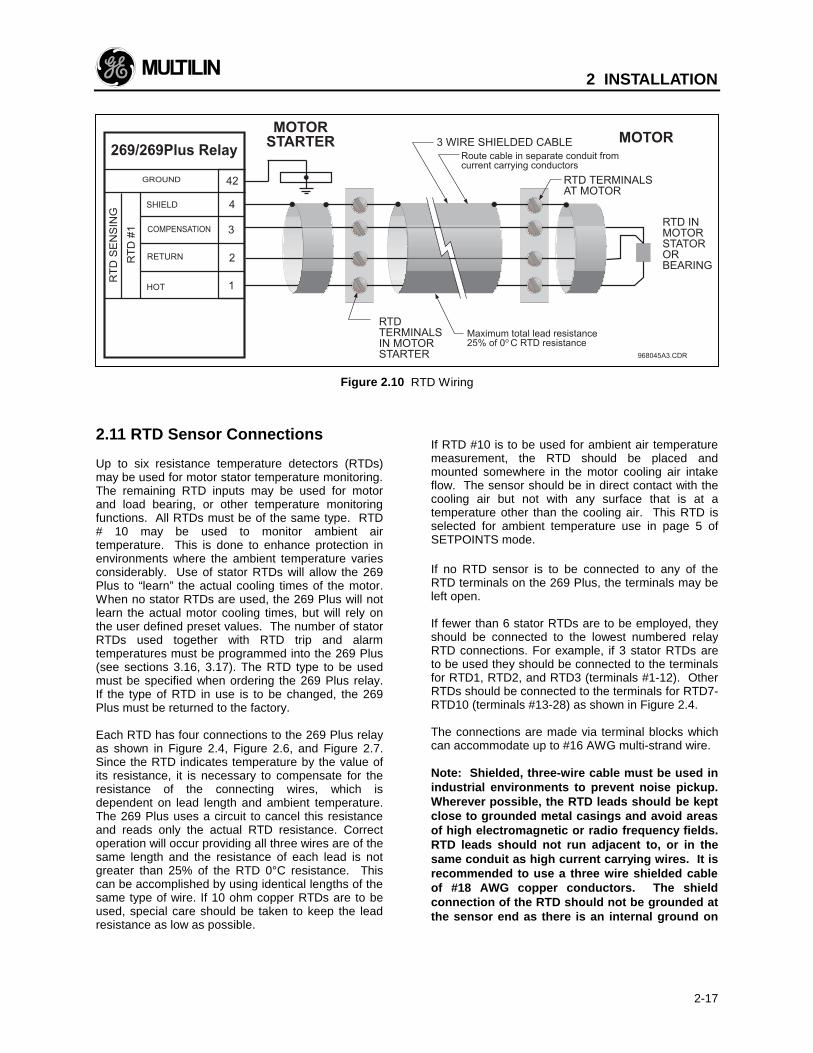
Figure 2.10 RTD Wiring
2.11 RTD Sensor Connections
Up to six resistance temperature detectors (RTDs)may be used for motor stator temperature monitoring.The remaining RTD inputs may be used for motorand load bearing, or other temperature monitoringfunctions. All RTDs must be of the same type. RTD# 10 may be used to monitor ambient airtemperature. This is done to enhance protection inenvironments where the ambient temperature variesconsiderably. Use of stator RTDs will allow the 269Plus to “learn” the actual cooling times of the motor.When no stator RTDs are used, the 269 Plus will notlearn the actual motor cooling times, but will rely onthe user defined preset values. The number of statorRTDs used together with RTD trip and alarmtemperatures must be programmed into the 269 Plus(see sections 3.16, 3.17). The RTD type to be usedmust be specified when ordering the 269 Plus relay.If the type of RTD in use is to be changed, the 269Plus must be returned to the factory.
Each RTD has four connections to the 269 Plus relayas shown in Figure 2.4, Figure 2.6, and Figure 2.7.Since the RTD indicates temperature by the value ofits resistance, it is necessary to compensate for theresistance of the connecting wires, which isdependent on lead length and ambient temperature.The 269 Plus uses a circuit to cancel this resistanceand reads only the actual RTD resistance. Correctoperation will occur providing all three wires are of thesame length and the resistance of each lead is notgreater than 25% of the RTD 0°C resistance. Thiscan be accomplished by using identical lengths of thesame type of wire. If 10 ohm copper RTDs are to beused, special care should be taken to keep the leadresistance as low as possible.
If RTD #10 is to be used for ambient air temperaturemeasurement, the RTD should be placed andmounted somewhere in the motor cooling air intakeflow. The sensor should be in direct contact with thecooling air but not with any surface that is at atemperature other than the cooling air. This RTD isselected for ambient temperature use in page 5 ofSETPOINTS mode.
If no RTD sensor is to be connected to any of theRTD terminals on the 269 Plus, the terminals may beleft open.
If fewer than 6 stator RTDs are to be employed, theyshould be connected to the lowest numbered relayRTD connections. For example, if 3 stator RTDs areto be used they should be connected to the terminalsfor RTD1, RTD2, and RTD3 (terminals #1-12). OtherRTDs should be connected to the terminals for RTD7-RTD10 (terminals #13-28) as shown in Figure 2.4.
The connections are made via terminal blocks whichcan accommodate up to #16 AWG multi-strand wire.
Note: Shielded, three-wire cable must be used inindustrial environments to prevent noise pickup.Wherever possible, the RTD leads should be keptclose to grounded metal casings and avoid areasof high electromagnetic or radio frequency fields.RTD leads should not run adjacent to, or in thesame conduit as high current carrying wires. It isrecommended to use a three wire shielded cableof #18 AWG copper conductors. The shieldconnection of the RTD should not be grounded atthe sensor end as there is an internal ground on
2 INSTALLATION
2-18
the 269 Plus. This arrangement prevents noisepickup that would otherwise occur fromcirculating currents due to differences in groundpotentials on a doubly grounded shield.
2.12 Emergency Restart Terminals
If it is desired to override relay trips or lock-outs andrestart the motor, a normally open keyswitch shouldbe installed between terminals 54 and 55.Momentarily shorting these terminals together willcause the thermal memory of the 269 Plus todischarge to 0% (if RTD input to thermal memory isenabled, thermal memory can be reduced to 0% bykeeping terminals 54 and 55 shorted together formore than 11 seconds; see section 3.20). TheEmergency Restart terminals can thus be used tooverride an OVERLOAD TRIP or a START INHIBITlock-out. Shorting the Emergency Restart terminalstogether will also decrement the relay's internalstarts/hour counter by 1 and therefore allow theoperator to override a STARTS/HOUR inhibit or timebetween Starts Inhibit.
Note: This option should be used only when animmediate restart after a lock-out trip is requiredfor process integrity or personnel safety.Discharging the thermal memory of the 269 Plusgives the relay an unrealistic value for the thermalcapacity remaining in the motor and it is possibleto thermally damage the motor by restarting it.Thus, complete protection may be compromisedin order to restart the motor using this feature.
A twisted pair of wires should be used. Connection tothe 269 Plus is made via a terminal block which canaccommodate up to #16 AWG multi-strand wire.
2.13 External Reset Terminals
An external reset switch, which operates similarly tothe keypad RESET key (see section 3.1), can beconnected to terminals 56 and 57 for remote resetoperation. The switch should have normally opencontacts. Upon closure of these contacts the relaywill be reset. This external reset is equivalent topressing the keypad RESET key. Keeping theExternal Reset terminals shorted together will causethe 269 Plus to be reset automatically whenevermotor conditions allow.
A twisted pair of wires should be used. Connection tothe 269 Plus is made via a terminal block which canaccommodate up to #16 AWG multi-strand wire.
2.14 Analog Output Terminals (Non-Isolated)
Terminals 58 and 59 of the 269 Plus are available foran analog current output representing one of:percentage of motor thermal capacity used; motorcurrent as a percentage of full load (i.e. 0.25-2.5uFLC); hottest stator RTD temperature as apercentage of 200°C; RTD #7 (bearing) temperatureas a percentage of 200°C; or CT secondary currentas a percentage of CT secondary amps rating. Thechoice of output is selected in page 5 of SETPOINTSmode. This selection can be made or changed at anytime without affecting the protective features of therelay.
The output current range is factory default at 4-20mA. However, this range may be enlarged in page 5of SETPOINTS mode. 4 mA output corresponds to alow scale reading (i.e. 0% thermal capacity used,0.25xFLC, 0oC hottest stator RTD temperature, RTD#7 temperature, or 0 A phase CT secondary current).20 mA output current corresponds to a high scalereading (i.e. 100% thermal capacity used, 2.5xFLC orlower phase current, 200oC for hottest stator RTD andRTD #7 temperature, or either 1 A or 5 A phase CTsecondary depending on the CT used).
This output is an active, non isolated current sourcesuitable for connection to a remote meter, chartrecorder, programmable controller, or computer load.Current levels are not affected by the total lead andload resistance as long as it does not exceed 300ohms for the 4-20 mA or the 0-20 mA range (2000ohms for 0-1 mA range). For readings greater than100% of full scale the output will saturate at 20.2 mA.
This analog output is not isolated. Terminal 58 isinternally connected to system ground. Consequentlythe negative terminal of the connected load devicemust be at ground potential. When isolation isnecessary, an external two-wire isolated transmittershould be used between the 269 Plus and the load(e.g. PLC).
A twisted pair of wires should be used. Connection tothe 269 Plus is made via a terminal block which canaccommodate up to #16 AWG multi-strand wire.
2.15 Differential Relay Terminals
Terminals 48 and 49 are provided for connection to adifferential relay. This allows an external differentialrelay to be connected to the 269 Plus. When thedifferential trip function is enabled on page 5 ofSETPOINTS, a contact closure between terminals 48and 49 will cause an immediate activation of theoutput relay assigned to the differential relay inputfunction. After a DIFFERENTIAL INPUT TRIP,terminals 48 and 49 must be open circuited, or thefunction disabled in order to reset the relay.
2 INSTALLATION
2-19
If no differential relay is to be used terminals 48 and49 should be left open, and the function disabled.
A twisted pair of wires should be used. Connection tothe 269 Plus is made via a terminal block which canaccommodate up to #16 AWG multi-strand wire.
2.16 Speed Switch Terminals
Terminals 50 and 51 are provided for connection toan external speed switch. This allows the 269 Plusrelay to utilize a speed device for locked rotorprotection. During a motor start attempt if no contactclosure between terminals 50 and 51 occurs withinthe "SPEED SWITCH TIME DELAY" (SETPOINTS,page 5) the output relay assigned to the speed switchfunction will activate. This function must be enabledin order for operation to occur (SETPOINTS, page 5).After a SPEED SWITCH TRIP terminals 50 and 51must be open circuited in order to reset the relay.
If no speed switch is to be used terminals 50 and 51should be left open.
A twisted pair of wires should be used. Connection tothe 269 Plus is made via a terminal block which canaccommodate up to #16 AWG multi-strand wire.
2.17 Programming Access Terminals
When a jumper wire is connected between ACCESSterminals 52 and 53 all setpoints and configurationscan be programmed using the keypad. Onceprogramming is complete the jumper will normally beremoved from these terminals. When this is done allactual and setpoint values can still be accessed forviewing; however, if an attempt is made to store anew setpoint value the message "ILLEGAL ACCESS"will appear on the display and the previous setpointwill remain intact. In this way all of the programmedsetpoints will remain secure and tamperproof.Alternatively, these terminals can be wired to anexternal keyswitch to permit setpoint programmingupon closure of the switch. For additional tamperproof protection, a software access code may beprogrammed on Page 6 of SETPOINTS. See section3 (Setup and Use).
A twisted pair of wires should be used for connectionto an external switch. Connection to the 269 Plus ismade via a terminal block which can accommodateup to #16 AWG multi-strand wire.
2.18 RS-485 Serial CommunicationsTerminals
Terminals 46 and 47 are provided for a digital serialcommunication link with other 269 Plus relays,computers, or programmable controllers. Up to 32269 Plus "SLAVES" can be connected to one"MASTER" (PC/DCS/PLC) as shown in Figure 2.11.The GE Multilin 269 Plus Relay CommunicationProtocol (MODBUS RTU Compatible Protocol) isdescribed in Chapter 4. Note that when using a 269Plus SLAVE, setpoints sent to the SLAVE must bewithin the ranges listed in Table 3-3.
Each communication link must have only oneMASTER. The MASTER should be centrally locatedand can be used to view ACTUAL VALUES andSETPOINTS from each relay SLAVE. SETPOINTS ineach SLAVE can also be changed from the MASTER.Each SLAVE in the communication link must beprogrammed with a different SLAVE ADDRESS.
To avoid contention and improper reading of dataensure that the following conditions are met:
1. Each communication link has only one MASTER.2. Each 269 Plus SLAVE in the link has a different
SLAVE ADDRESS.
The wires joining relays in the communication linkshould be a shielded twisted pair (typically 24AWG).These wires should be routed away from high powerAC lines and other sources of electrical noise. Thetotal length of the communications link should notexceed 4000 feet using 24AWG shielded twisted pair.When connecting units in a communication link each269 Plus relay must have terminal 47 connected toterminal 47 of the next unit in the link, and terminal 46connected to terminal 46.
2 INSTALLATION
2-20
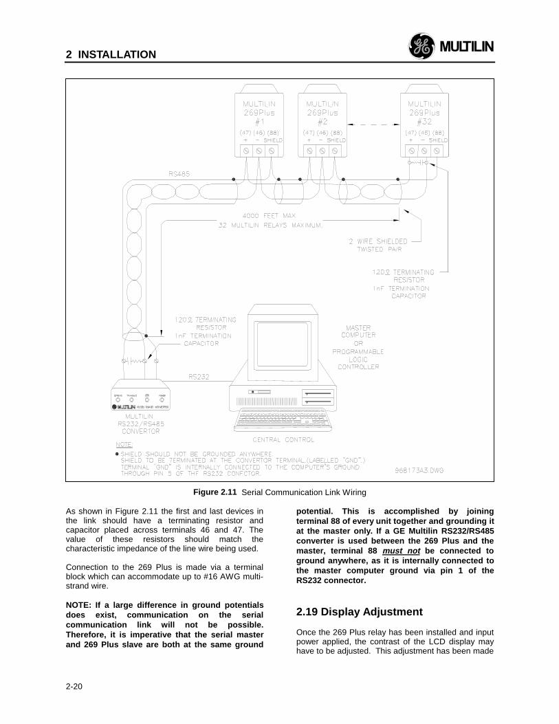
Figure 2.11 Serial Communication Link Wiring
As shown in Figure 2.11 the first and last devices inthe link should have a terminating resistor andcapacitor placed across terminals 46 and 47. Thevalue of these resistors should match thecharacteristic impedance of the line wire being used.
Connection to the 269 Plus is made via a terminalblock which can accommodate up to #16 AWG multi-strand wire.
NOTE: If a large difference in ground potentialsdoes exist, communication on the serialcommunication link will not be possible.Therefore, it is imperative that the serial masterand 269 Plus slave are both at the same ground
potential. This is accomplished by joiningterminal 88 of every unit together and grounding itat the master only. If a GE Multilin RS232/RS485converter is used between the 269 Plus and themaster, terminal 88 must not be connected toground anywhere, as it is internally connected tothe master computer ground via pin 1 of theRS232 connector.
2.19 Display Adjustment
Once the 269 Plus relay has been installed and inputpower applied, the contrast of the LCD display mayhave to be adjusted. This adjustment has been made
2 INSTALLATION
2-21
at the factory for average lighting conditions and astandard viewing angle but can be changed tooptimize the display readability in differentenvironments. To alter the display contrast thetrimpot on the rear of the unit marked "CONTRAST"must be adjusted with a small slotted screwdriver.
2.20 Front Panel Faceplate
The front panel faceplate is composed of apolycarbonate material that can be cleaned withisopropyl or denatured alcohol, freon, naphtha, ormild soap and water.
2.21 Spare Input Terminals
Terminals 44 and 45 are provided for an additionalrelay contact input. A contact closure between theseterminals will cause a "SPARE INPUT TRIP" and/or a"SPARE INPUT ALARM" after the appropriate timedelay (page 5 of SETPOINTS). These terminals mustbe open circuited in order to reset the relay after aSPARE INPUT TRIP or ALARM.
A twisted pair of wires should be used. Connection tothe 269 Plus is made via a terminal block which canaccommodate up to #16 AWG multi-strand wire.
2.22 269 Drawout Relay
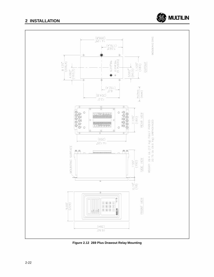
The model 269 Plus relay is available in a drawoutcase option. The operation of the relay is the same asdescribed elsewhere in this manual except for thedifferences noted in this section. The physicaldimensions of the drawout relay are as shown inFigure 2.12. The relay should be mounted as shownin Figure 2.13.
The drawout 269 Plus relay can be removed fromservice without causing motor shut-down. This canbe useful for replacing, calibrating, or testing units.
RELAY MOUNTING - Make cutout as shown and drillsix 7/32" holes on mounting panel. Approximately 2-1/2" should be clear at the top and bottom of thecutout in the panel for the hinged door. Ensure thatthe five #6-32 nuts are removed from the threadedstuds in the mounting flange and that the drawoutchassis has been removed from the drawout case.Install the case from the rear of the mounting panelby aligning the five #6-32 threaded case studs to thepreviously drilled holes. With the studs protrudingthrough the holes secure the case on the right handside with two #6-32 nuts provided. Install the hingeddoor on the front of the mounting panel using three#6-32 nuts provided.
FIELD ADJUSTMENTS - There are four screwsholding the plastic 269 Plus case to the drawout
cradle. These screw into holes which are slotted tocompensate for panel thickness. If the 269 Plus caseis mounted at the extreme end of the slot intended forthin panels, the relay will not seat properly and thedoor will not shut over the relay when installed on athick panel. Loosening the screws and moving therelay forward before retightening will fix the problem.
RELAY REMOVAL - Open the hinged door. Nextremove the two ten finger connecting plugs makingsure the top one is removed first. Swivel the cradle-to-case hinged levers at each end of the 269 Pluscradle assembly and slide the assembly out of thecase.
RELAY INSTALLATION - Slide the 269 Plus cradleassembly completely into the case. Swivel the hingedlevers in to lock the 269 Plus cradle assembly into thedrawout case. Install the two ten finger connectingplugs making sure the bottom plug is installed first.Close the hinged door and secure with the captivescrew.
NOTE: There must be at least ½" clearance on thehinged side of the drawout relay to allow the doorto open.
IMPORTANT NOTE: When removing the drawoutrelay cradle assembly the top ten finger connectingplug must be withdrawn first. This isolates the 269Plus output relay contacts before power is removedfrom the relay. When installing the drawout relaycradle assembly the bottom ten finger connectingplug must be installed first. This causes power to beapplied to the 269 Plus relay before the output relaycontacts are placed in the circuit.
After a 269 Plus relay cradle assembly has beenremoved from the drawout case it is recommendedthat the hinged door be closed in order to reduce therisk of electric shock.
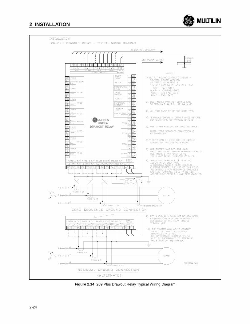
Due to the hardware configuration of the drawoutrelay shorting bars, the RELAY FAILSAFE CODE(SETPOINTS, page 5) should not be changed withoutconsulting the factory. Spare shorting bars areincluded with each drawout specifically for therequired modification. Wiring for the 269 Plus drawoutis shown in Figure 2.14. If it is required that any of theoutput relay configurations in Figure 2.14 be differentthan shown, this information must be stated when therelay is ordered.
The 269 Plus Drawout does not meet IEC947-1 andIEC1010-1.
No special ventilation requirements need to beobserved during the installation of this unit.
2 INSTALLATION
2-22
Figure 2.12 269 Plus Drawout Relay Mounting

2 INSTALLATION
2-23
Figure 2.13 269 Plus Drawout Relay Mounting
2 INSTALLATION
2-24
Figure 2.14 269 Plus Drawout Relay Typical Wiring Diagram
2 INSTALLATION
2-25
2.19 Meter Option Installation
The addition of a GE Multilin MPM (Motor ProtectionMeter) option allows the 269 Plus user to monitor andassign protective features based on voltage andpower measurement. Either meter also provides fourisolated analog outputs representing: Current, Watts,Vars, and Power Factor. These outputs from themeter can provide the signals for the control of themotor or a process.
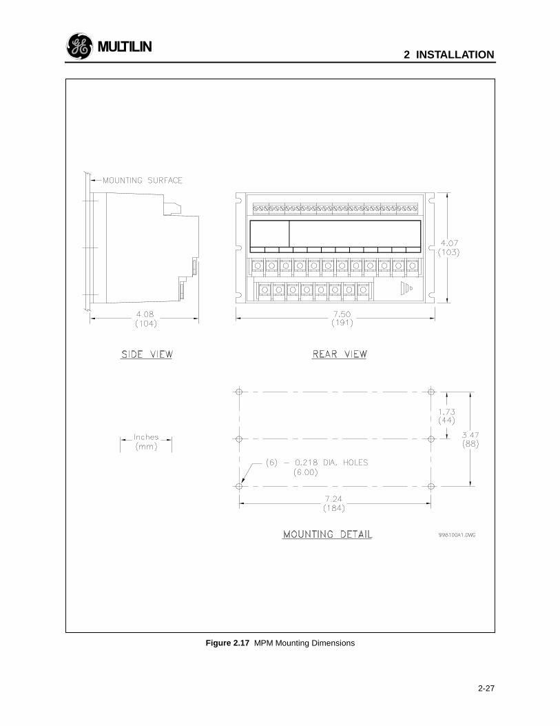
MPM External ConnectionsPhysical dimensions for the MPM and the requiredcutout dimensions are shown in Figure 2.17. Oncethe cutout and mounting holes are made in the panel,use the eight #6 self tapping screws to secure therelay.
MPM WiringSignal wiring is to box terminals that canaccommodate wire as large as 12 gauge. CT, VT andcontrol power connections are made using #8 screwring terminals that can accept wire as large as 8gauge.
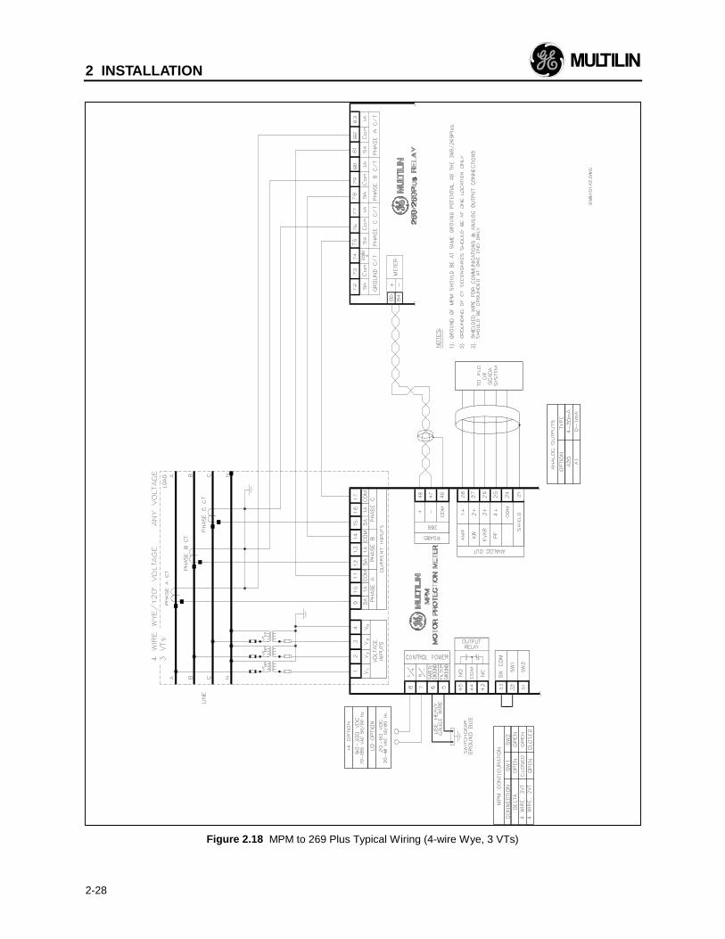
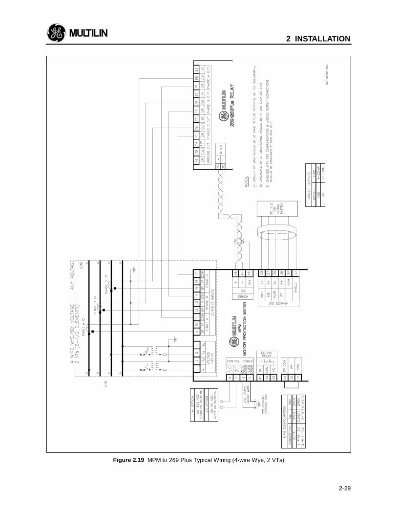
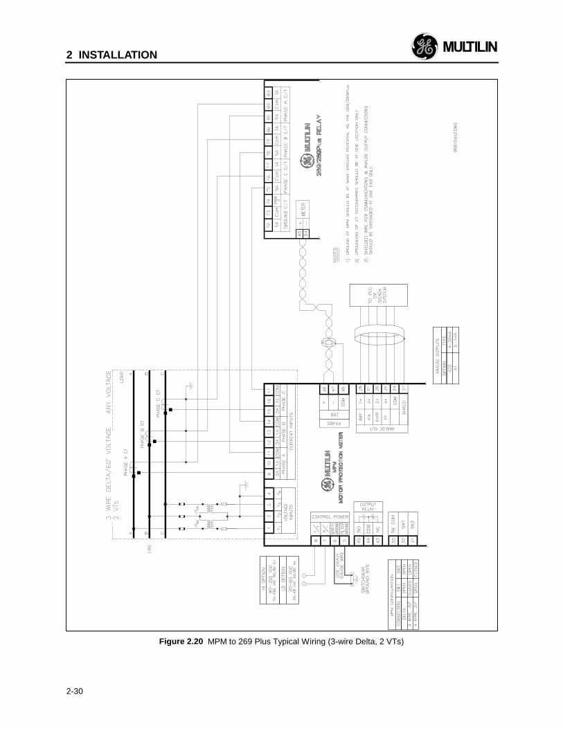
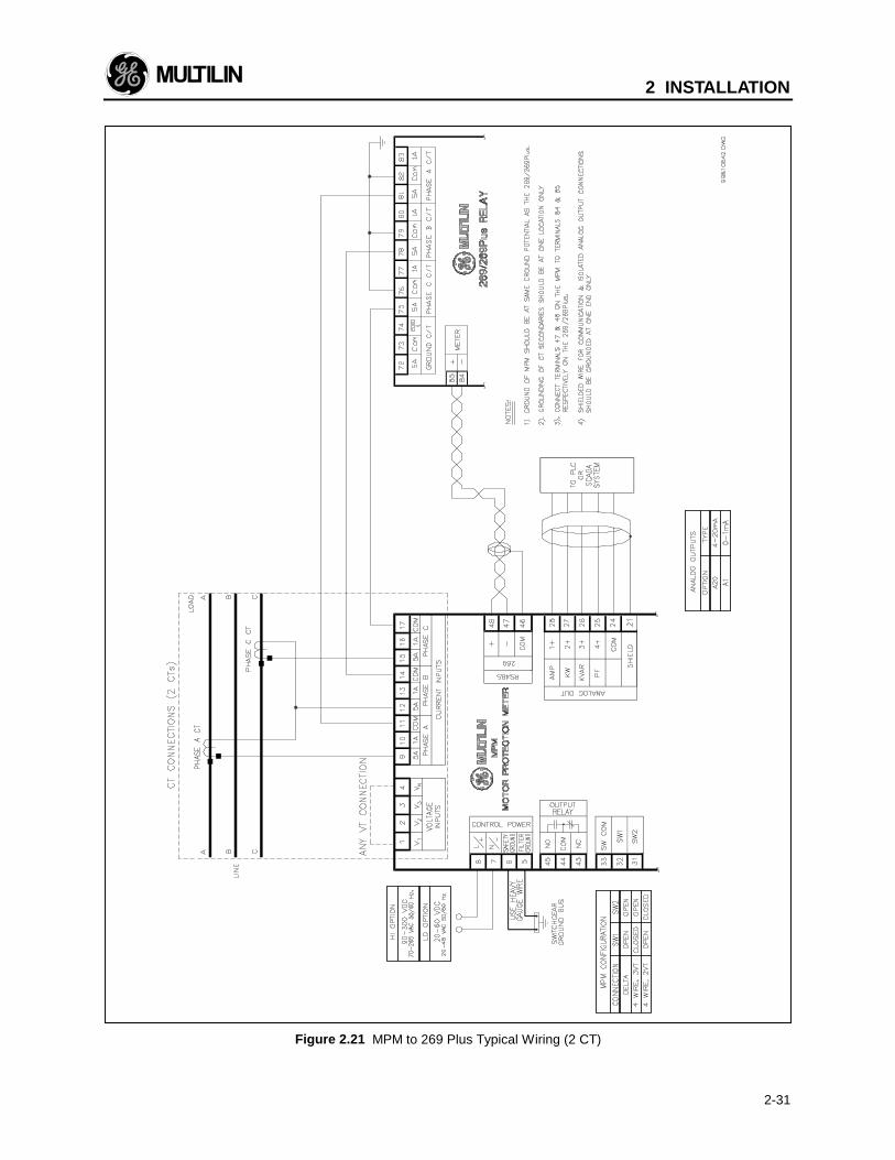
Consult the wiring Figure 2.18 through 2.22 forsuggested wiring. For proper operation of the MPMand 269 Plus set, MPM control power and phaseCTs/VTs must be connected. Other features may bewired depending on the MPM model ordered.
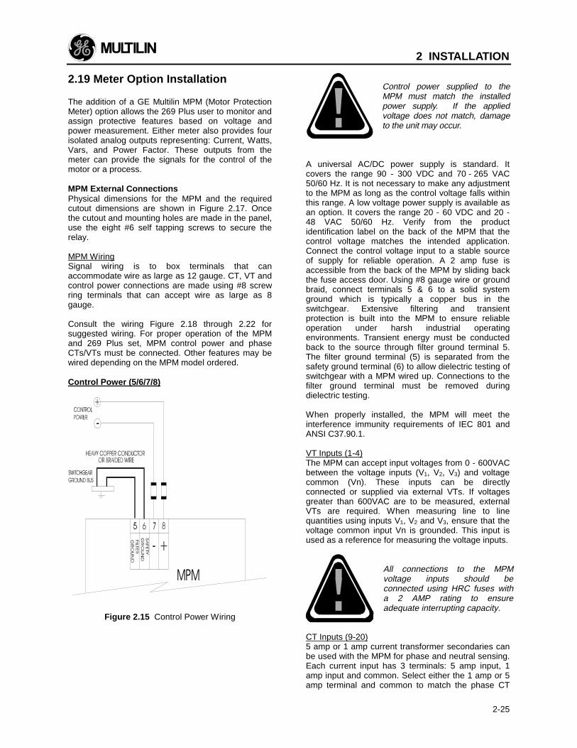
Control Power (5/6/7/8)
030
Figure 2.15 Control Power Wiring
Control power supplied to theMPM must match the installedpower supply. If the appliedvoltage does not match, damageto the unit may occur.
A universal AC/DC power supply is standard. Itcovers the range 90 - 300 VDC and 70 - 265 VAC50/60 Hz. It is not necessary to make any adjustmentto the MPM as long as the control voltage falls withinthis range. A low voltage power supply is available asan option. It covers the range 20 - 60 VDC and 20 -48 VAC 50/60 Hz. Verify from the productidentification label on the back of the MPM that thecontrol voltage matches the intended application.Connect the control voltage input to a stable sourceof supply for reliable operation. A 2 amp fuse isaccessible from the back of the MPM by sliding backthe fuse access door. Using #8 gauge wire or groundbraid, connect terminals 5 & 6 to a solid systemground which is typically a copper bus in theswitchgear. Extensive filtering and transientprotection is built into the MPM to ensure reliableoperation under harsh industrial operatingenvironments. Transient energy must be conductedback to the source through filter ground terminal 5.The filter ground terminal (5) is separated from thesafety ground terminal (6) to allow dielectric testing ofswitchgear with a MPM wired up. Connections to thefilter ground terminal must be removed duringdielectric testing.
When properly installed, the MPM will meet theinterference immunity requirements of IEC 801 andANSI C37.90.1.
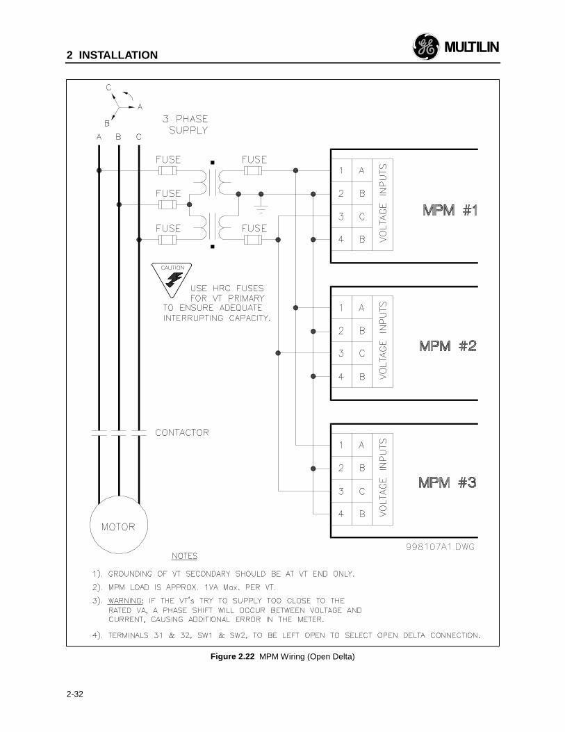
VT Inputs (1-4)The MPM can accept input voltages from 0 - 600VACbetween the voltage inputs (V1, V2, V3) and voltagecommon (Vn). These inputs can be directlyconnected or supplied via external VTs. If voltagesgreater than 600VAC are to be measured, externalVTs are required. When measuring line to linequantities using inputs V1, V2 and V3, ensure that thevoltage common input Vn is grounded. This input isused as a reference for measuring the voltage inputs.
All connections to the MPMvoltage inputs should beconnected using HRC fuses witha 2 AMP rating to ensureadequate interrupting capacity.
CT Inputs (9-20)5 amp or 1 amp current transformer secondaries canbe used with the MPM for phase and neutral sensing.Each current input has 3 terminals: 5 amp input, 1amp input and common. Select either the 1 amp or 5amp terminal and common to match the phase CT
2 INSTALLATION
2-26
secondary. Correct polarity as indicated in the wiringFigure 2.17 through Figure 2.21 is essential forcorrect measurement of all power quantities.
CTs should be selected to be capable of supplyingthe required current to the total secondary load whichincludes the MPM relay burden of 0.2 VA at ratedsecondary current and the connection wiring burden.
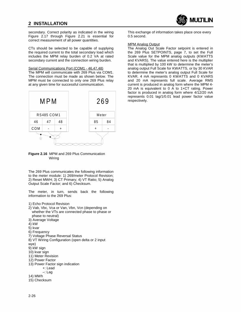
Serial Communications Port (COM1 - 46,47,48)The MPM will communicate with 269 Plus via COM1.The connection must be made as shown below. TheMPM must be connected to only one 269 Plus relayat any given time for successful communication.
M P M
46 47 48
C O M - +
R S 485 C O M 1
269
85 84
+ -
M e te r
Figure 2.16 MPM and 269 Plus CommunicationWiring
The 269 Plus communicates the following informationto the meter module: 1) 269/meter Protocol Revision;2) Reset MWH; 3) CT Primary; 4) VT Ratio; 5) AnalogOutput Scale Factor; and 6) Checksum.
The meter, in turn, sends back the followinginformation to the 269 Plus:
1) Echo Protocol Revision2) Vab, Vbc, Vca or Van, Vbn, Vcn (depending on
whether the VTs are connected phase to phase orphase to neutral)
3) Average Voltage4) kW5) kvar6) Frequency7) Voltage Phase Reversal Status8) VT Wiring Configuration (open delta or 2 inputwye)9) kW sign10) kvar sign11) Meter Revision12) Power Factor13) Power Factor sign indication
+: Lead–: Lag
14) MWh15) Checksum
This exchange of information takes place once every0.5 second.
MPM Analog OutputThe Analog Out Scale Factor setpoint is entered inthe 269 Plus SETPOINTS, page 7, to set the FullScale value for the MPM analog outputs (KWATTSand KVARS). The value entered here is the multiplierthat is multiplied by 100 kW to determine the meter’sanalog output Full Scale for KWATTS, or by 30 KVARto determine the meter’s analog output Full Scale forKVAR. 4 mA represents 0 KWATTS and 0 KVARSand 20 mA represents full scale. Average RMScurrent is produced in analog form where the MPM 4-20 mA is equivalent to 0 A to 1×CT rating. Powerfactor is produced in analog form where 4/12/20 mArepresents 0.01 lag/1/0.01 lead power factor valuerespectively.
2 INSTALLATION
2-27
Figure 2.17 MPM Mounting Dimensions
2 INSTALLATION
2-28
Figure 2.18 MPM to 269 Plus Typical Wiring (4-wire Wye, 3 VTs)
2 INSTALLATION
2-29
Figure 2.19 MPM to 269 Plus Typical Wiring (4-wire Wye, 2 VTs)
2 INSTALLATION
2-30
Figure 2.20 MPM to 269 Plus Typical Wiring (3-wire Delta, 2 VTs)
2 INSTALLATION
2-31
Figure 2.21 MPM to 269 Plus Typical Wiring (2 CT)
2 INSTALLATION
2-32
Figure 2.22 MPM Wiring (Open Delta)
3 SETUP AND USE
3-1
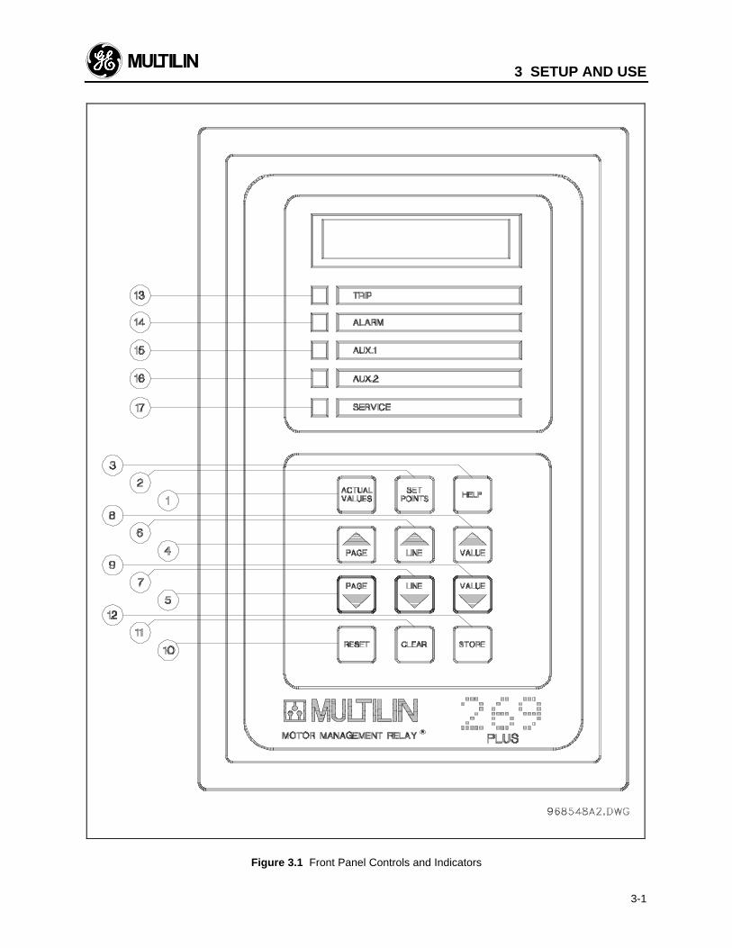
Figure 3.1 Front Panel Controls and Indicators
3 SETUP AND USE
3-2
3.1 Controls and Indicators
Once the 269 Plus relay has been wired and controlpower applied, it is ready to be programmed for thegiven application. Programming is accomplished using
the 12 position keypad and 48 character alphanumericdisplay shown in Figure 3.1. The function of each keyon the keypad and each of the indicators is briefly ex-plained in Table 3-1.
Table 3-1 Controls and Indicators
No. Name Description
1 FUNCTION: The ACTUAL VALUES key allows the user to examine all of the actualmotor operating parameters. There are seven pages of ACTUAL VALUES data:
page 1: Phase Current Datapage 2: RTD Temperature Datapage 3: Motor Capacity Datapage 4: Statistical Datapage 5: Pre-trip Datapage 6: Learned Parameterspage 7: Metering DataEFFECT: Pressing this key will put the relay into ACTUAL VALUES mode. Theflash message,
ACTUAL VALUES HAS SEVENACTUAL VALUES HAS SEVENPAGES OF DATAPAGES OF DATA
will be displayed for 2 seconds. The beginning of page 1 of ACTUAL VALUESmode will then be shown:
PAGE 1: ACTUAL VALUESPAGE 1: ACTUAL VALUESPHASE CURRENT DATAPHASE CURRENT DATA
USE: This key can be pressed at any time, in any mode to view actual motor val-ues. To go from page to page the PAGE UP and PAGE DOWN keys can be used.To go from line to line within a page the LINE UP and LINE DOWN keys can beused.
2 FUNCTION: The SET POINTS key allows the user to examine and alter all trip,alarm, and other relay setpoints. There are seven pages of setpoints data:
page 1: Motor Amps Setpointspage 2: RTD Setpointspage 3: O/L Curve Setpointspage 4: Relay Configurationpage 5: System Configurationpage 6: Multilin Service Codespage 7: Metering SetpointsEFFECT: Pressing this key will put the relay into SETPOINTS mode. The flashmessage,
SETPOINTS HAS SEVENSETPOINTS HAS SEVENPAGES OF DATAPAGES OF DATA
will be displayed for 2 seconds. The beginning of page 1 of SETPOINTS mode willthen be shown:
PAGE 1: SETPOINT VALUESPAGE 1: SETPOINT VALUESMOTOR AMPS SETPOINTSMOTOR AMPS SETPOINTS
3 SETUP AND USENo. Name Description
3-3
USE: This key can be pressed at any time, in any mode, to view or alter relay set-points. To go from page to page the PAGE UP and PAGE DOWN keys can beused. To go from line to line within a page the LINE UP and LINE DOWN keys canbe used. To alter a setpoint, the VALUE UP and VALUE DOWN keys can be used.All setpoints will increment and decrement to pre-determined limits. When the de-sired value is reached, the STORE key must be used to save the new setpoint. If analtered setpoint is not stored the previous value will still be in effect. If the Accessjumper is not installed a STORE will not be allowed and the flash message"ILLEGAL ACCESS" will be displayed for 2 seconds.
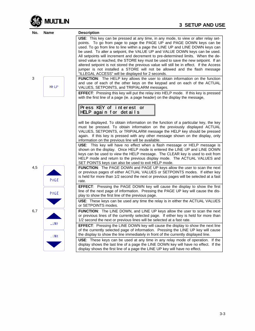
3 FUNCTION: The HELP key allows the user to obtain information on the functionand use of each of the other keys on the keypad and on each of the ACTUALVALUES, SETPOINTS, and TRIP/ALARM messages.
EFFECT: Pressing this key will put the relay into HELP mode. If this key is pressedwith the first line of a page (ie. a page header) on the display the message,
Press KEY of interest orPress KEY of interest orHELP again for detailsHELP again for details
will be displayed. To obtain information on the function of a particular key, the keymust be pressed. To obtain information on the previously displayed ACTUALVALUES, SETPOINTS, or TRIP/ALARM message the HELP key should be pressedagain. If this key is pressed with any other message shown on the display, onlyinformation on the previous line will be available.USE: This key will have no effect when a flash message or HELP message isshown on the display. Once HELP mode is entered the LINE UP and LINE DOWNkeys can be used to view the HELP message. The CLEAR key is used to exit fromHELP mode and return to the previous display mode. The ACTUAL VALUES andSET POINTS keys can also be used to exit HELP mode.
4,5 FUNCTION: The PAGE DOWN and PAGE UP keys allow the user to scan the nextor previous pages of either ACTUAL VALUES or SETPOINTS modes. If either keyis held for more than 1/2 second the next or previous pages will be selected at a fastrate.
EFFECT: Pressing the PAGE DOWN key will cause the display to show the firstline of the next page of information. Pressing the PAGE UP key will cause the dis-play to show the first line of the previous page.
USE: These keys can be used any time the relay is in either the ACTUAL VALUESor SETPOINTS modes.
6,7 FUNCTION: The LINE DOWN, and LINE UP keys allow the user to scan the nextor previous lines of the currently selected page. If either key is held for more than1/2 second the next or previous lines will be selected at a fast rate.
EFFECT: Pressing the LINE DOWN key will cause the display to show the next lineof the currently selected page of information. Pressing the LINE UP key will causethe display to show the line immediately in front of the currently displayed line.
USE: These keys can be used at any time in any relay mode of operation. If thedisplay shows the last line of a page the LINE DOWN key will have no effect. If thedisplay shows the first line of a page the LINE UP key will have no effect.
3 SETUP AND USENo. Name Description
3-4
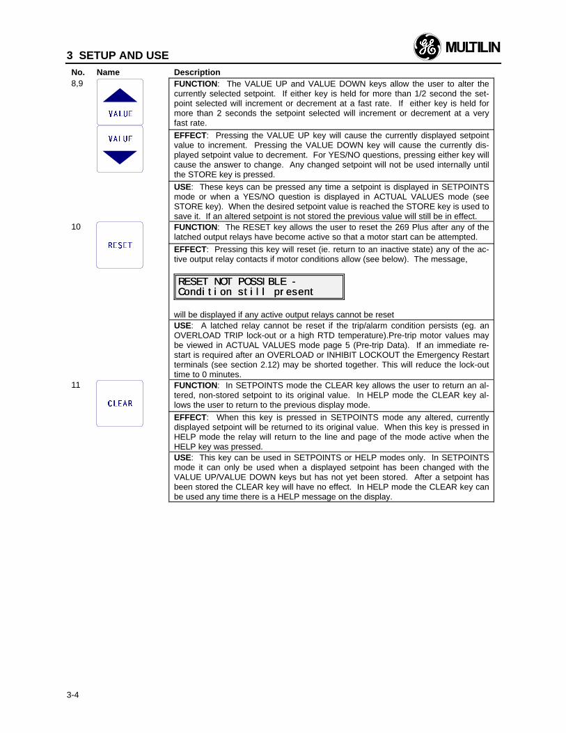
8,9 FUNCTION: The VALUE UP and VALUE DOWN keys allow the user to alter thecurrently selected setpoint. If either key is held for more than 1/2 second the set-point selected will increment or decrement at a fast rate. If either key is held formore than 2 seconds the setpoint selected will increment or decrement at a veryfast rate.
EFFECT: Pressing the VALUE UP key will cause the currently displayed setpointvalue to increment. Pressing the VALUE DOWN key will cause the currently dis-played setpoint value to decrement. For YES/NO questions, pressing either key willcause the answer to change. Any changed setpoint will not be used internally untilthe STORE key is pressed.
USE: These keys can be pressed any time a setpoint is displayed in SETPOINTSmode or when a YES/NO question is displayed in ACTUAL VALUES mode (seeSTORE key). When the desired setpoint value is reached the STORE key is used tosave it. If an altered setpoint is not stored the previous value will still be in effect.
10 FUNCTION: The RESET key allows the user to reset the 269 Plus after any of thelatched output relays have become active so that a motor start can be attempted.
EFFECT: Pressing this key will reset (ie. return to an inactive state) any of the ac-tive output relay contacts if motor conditions allow (see below). The message,
RESET NOT POSSIBLE -RESET NOT POSSIBLE -Condition still presentCondition still present
will be displayed if any active output relays cannot be resetUSE: A latched relay cannot be reset if the trip/alarm condition persists (eg. anOVERLOAD TRIP lock-out or a high RTD temperature).Pre-trip motor values maybe viewed in ACTUAL VALUES mode page 5 (Pre-trip Data). If an immediate re-start is required after an OVERLOAD or INHIBIT LOCKOUT the Emergency Restartterminals (see section 2.12) may be shorted together. This will reduce the lock-outtime to 0 minutes.
11 FUNCTION: In SETPOINTS mode the CLEAR key allows the user to return an al-tered, non-stored setpoint to its original value. In HELP mode the CLEAR key al-lows the user to return to the previous display mode.
EFFECT: When this key is pressed in SETPOINTS mode any altered, currentlydisplayed setpoint will be returned to its original value. When this key is pressed inHELP mode the relay will return to the line and page of the mode active when theHELP key was pressed.USE: This key can be used in SETPOINTS or HELP modes only. In SETPOINTSmode it can only be used when a displayed setpoint has been changed with theVALUE UP/VALUE DOWN keys but has not yet been stored. After a setpoint hasbeen stored the CLEAR key will have no effect. In HELP mode the CLEAR key canbe used any time there is a HELP message on the display.
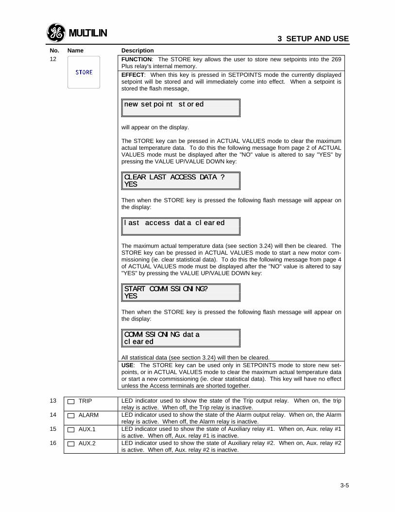
3 SETUP AND USENo. Name Description
3-5
12 FUNCTION: The STORE key allows the user to store new setpoints into the 269Plus relay's internal memory.
EFFECT: When this key is pressed in SETPOINTS mode the currently displayedsetpoint will be stored and will immediately come into effect. When a setpoint isstored the flash message,
new setpoint storednew setpoint stored
will appear on the display.
The STORE key can be pressed in ACTUAL VALUES mode to clear the maximumactual temperature data. To do this the following message from page 2 of ACTUALVALUES mode must be displayed after the "NO" value is altered to say "YES" bypressing the VALUE UP/VALUE DOWN key:
CLEAR LAST ACCESS CLEAR LAST ACCESS DATA ?DATA ?YESYES
Then when the STORE key is pressed the following flash message will appear onthe display:
last access data clearedlast access data cleared
The maximum actual temperature data (see section 3.24) will then be cleared. TheSTORE key can be pressed in ACTUAL VALUES mode to start a new motor com-missioning (ie. clear statistical data). To do this the following message from page 4of ACTUAL VALUES mode must be displayed after the "NO" value is altered to say"YES" by pressing the VALUE UP/VALUE DOWN key:
START COMMISSIONING?START COMMISSIONING?YESYES
Then when the STORE key is pressed the following flash message will appear onthe display:
COMMISSIONING dataCOMMISSIONING dataclearedcleared
All statistical data (see section 3.24) will then be cleared.USE: The STORE key can be used only in SETPOINTS mode to store new set-points, or in ACTUAL VALUES mode to clear the maximum actual temperature dataor start a new commissioning (ie. clear statistical data). This key will have no effectunless the Access terminals are shorted together.
13 TRIP LED indicator used to show the state of the Trip output relay. When on, the triprelay is active. When off, the Trip relay is inactive.
14 ALARM LED indicator used to show the state of the Alarm output relay. When on, the Alarmrelay is active. When off, the Alarm relay is inactive.
15 AUX.1 LED indicator used to show the state of Auxiliary relay #1. When on, Aux. relay #1is active. When off, Aux. relay #1 is inactive.
16 AUX.2 LED indicator used to show the state of Auxiliary relay #2. When on, Aux. relay #2is active. When off, Aux. relay #2 is inactive.
3 SETUP AND USENo. Name Description
3-6
17 SERVICE LED indicator used to show the result of the 269 Plus self-test feature. Whenflashing, the relay has failed the self-test and service is required. When on steady,the supply voltage may be too low. This LED may be on momentarily during relaypower up.
3.2 269 Plus Relay Display Modes
The 269 Plus relay display is used for viewing actualmotor values, setpoint values, HELP messages, andTRIP/ALARM messages. This is accomplished byhaving the relay in one of four possible modes of op-eration:
1. ACTUAL VALUES mode2. SETPOINTS mode3. HELP mode4. TRIP/ALARM mode
The relay will operate correctly, giving full motor pro-tection, regardless of which display mode is currently ineffect. The different modes affect only the data thatappears on the 269 Plus relay's 48 character alphanu-meric display.
TRIP/ALARM mode can only be entered by having oneor more of the trip or alarm level setpoints exceeded.The other display modes can be entered using theACTUAL VALUES, SET POINTS, or HELP keys (seesection 3.1).
The ACTUAL VALUES and SETPOINTS modes arebased on a book-like system of "pages" and "lines".One line from any page may be displayed at any giventime. To "turn" a page, the PAGE UP and PAGEDOWN keys are used. To scan the lines on a page theLINE UP and LINE DOWN keys are used. In the HELPand TRIP/ALARM modes only the LINE UP and LINEDOWN keys are needed.
When control power is applied to the relay the followingpower up message will be displayed:
MULTILIN 269 PLUS RELAYMULTILIN 269 PLUS RELAYREVISION REVISION XXX XX/XXXXX XX/XX
After this the display will show, (factory default set-tings)
I1 I1= XXX I2= XXX= XXX I2= XXX I3= XXX (AMPS) I3= XXX (AMPS)
which is in page 1 of ACTUAL VALUES mode.
A description of each display mode is given in the fol-lowing sections.
3.3 ACTUAL VALUES Mode
In ACTUAL VALUES mode, any of the parametersmonitored or calculated by the 269 Plus relay may beviewed by the user. This mode is divided into sevenseparate pages of data each of which contains a differ-ent group of actual motor values. The seven pagesand the lines in each page are as shown in Table 3-2.
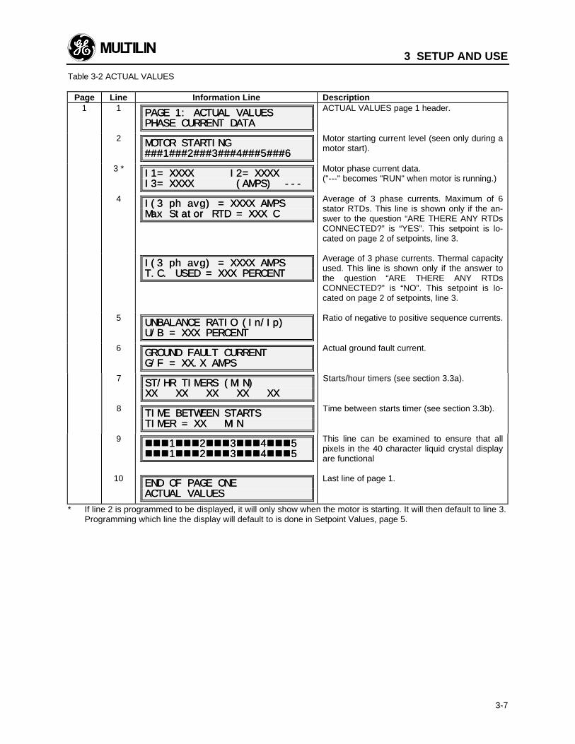
3 SETUP AND USE
3-7
Table 3-2 ACTUAL VALUES
Page Line Information Line Description1 1
PAGE 1: ACTUAL VALUESPAGE 1: ACTUAL VALUESPHASE CURRENT DATAPHASE CURRENT DATA
ACTUAL VALUES page 1 header.
2MOTOR STARTINGMOTOR STARTING###1###2###3###4###5###6###1###2###3###4###5###6
Motor starting current level (seen only during amotor start).
3 * I1= XXXX I2= XXXXI1= XXXX I2= XXXXI3= XXXX (AMPS) ---I3= XXXX (AMPS) ---
Motor phase current data.("---" becomes "RUN" when motor is running.)
4I(3 I(3 ph ph avg) = XXXX AMPSavg) = XXXX AMPSMax Stator RTD = XXX CMax Stator RTD = XXX C
Average of 3 phase currents. Maximum of 6stator RTDs. This line is shown only if the an-swer to the question “ARE THERE ANY RTDsCONNECTED?” is “YES”. This setpoint is lo-cated on page 2 of setpoints, line 3.
I(3 I(3 ph ph avg) = XXXX AMPSavg) = XXXX AMPST.C. USED = XXX PERCENTT.C. USED = XXX PERCENT
Average of 3 phase currents. Thermal capacityused. This line is shown only if the answer tothe question “ARE THERE ANY RTDsCONNECTED?” is “NO”. This setpoint is lo-cated on page 2 of setpoints, line 3.
5UNBALANCE RATIO (In/UNBALANCE RATIO (In/Ip)Ip)U/B = XXX PERCENTU/B = XXX PERCENT
Ratio of negative to positive sequence currents.
6GROUND FAULT CURRENTGROUND FAULT CURRENTG/F = XX.X AMPSG/F = XX.X AMPS
Actual ground fault current.
7 ST/HR TIMERS (MIN)ST/HR TIMERS (MIN)XX XX XX XX XX XX XX XX XXXX
Starts/hour timers (see section 3.3a).
8 TIME BETWEEN STARTSTIME BETWEEN STARTSTIMER = XX MINTIMER = XX MIN
Time between starts timer (see section 3.3b).
9 nnnnnn11nnnnnn22nnnnnn33nnnnnn44nnnnnn55nnnnnn11nnnnnn22nnnnnn33nnnnnn44nnnnnn55
This line can be examined to ensure that allpixels in the 40 character liquid crystal displayare functional
10 END OF PAGE ONEEND OF PAGE ONEACTUAL VALUESACTUAL VALUES
Last line of page 1.
* If line 2 is programmed to be displayed, it will only show when the motor is starting. It will then default to line 3.Programming which line the display will default to is done in Setpoint Values, page 5.
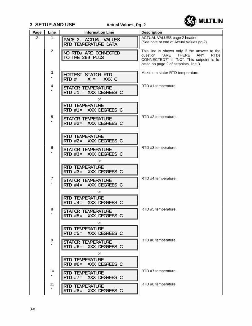
3 SETUP AND USE Actual Values, Pg. 2
Page Line Information Line Description
3-8
2 1 PAGE 2: ACTUAL VALUESPAGE 2: ACTUAL VALUESRTD TEMPERATURE DATARTD TEMPERATURE DATA
ACTUAL VALUES page 2 header.(See note at end of Actual Values pg.2).
2 NO RTDs ARE CONNECTEDNO RTDs ARE CONNECTEDTO THE 269 PLUSTO THE 269 PLUS
This line is shown only if the answer to thequestion “ARE THERE ANY RTDsCONNECTED?” is “NO”. This setpoint is lo-cated on page 2 of setpoints, line 3.
3•
HOTTEST STATOR RTDHOTTEST STATOR RTDRTD # X = XXX CRTD # X = XXX C
Maximum stator RTD temperature.
4•
STATOR TEMPERATURESTATOR TEMPERATURERTD #1= XXX DEGREES CRTD #1= XXX DEGREES C
or
RTD TEMPERATURERTD TEMPERATURERTD #1= XXX DEGREES CRTD #1= XXX DEGREES C
RTD #1 temperature.
5•
STATOR TEMPERATURESTATOR TEMPERATURERTD #2= XXX DEGREES CRTD #2= XXX DEGREES C
or
RTD TEMPERATURERTD TEMPERATURERTD #2= XXX DEGREES CRTD #2= XXX DEGREES C
RTD #2 temperature.
6•
STATOR TEMPERATURESTATOR TEMPERATURERTD #3= XXX DEGREES CRTD #3= XXX DEGREES C
or
RTD TEMPERATURERTD TEMPERATURERTD #3= XXX DEGREES CRTD #3= XXX DEGREES C
RTD #3 temperature.
7•
STATOR TEMPERATURESTATOR TEMPERATURERTD #4= XXX DEGREES CRTD #4= XXX DEGREES C
or
RTD TEMPERATURERTD TEMPERATURERTD #4= XXX DEGREES CRTD #4= XXX DEGREES C
RTD #4 temperature.
8•
STATOR TEMPERATURESTATOR TEMPERATURERTD #5= XXX DEGREES CRTD #5= XXX DEGREES C
or
RTD TEMPERATURERTD TEMPERATURERTD #5= XXX DEGREES CRTD #5= XXX DEGREES C
RTD #5 temperature.
9•
STATOR TEMPERATURESTATOR TEMPERATURERTD #6= XXX DEGREES CRTD #6= XXX DEGREES C
or
RTD TEMPERATURERTD TEMPERATURERTD #6= XXX DEGREES CRTD #6= XXX DEGREES C
RTD #6 temperature.
10•
RTD TEMPERATURERTD TEMPERATURERTD #7= XXX DEGREES CRTD #7= XXX DEGREES C
RTD #7 temperature.
11•
RTD TEMPERATURERTD TEMPERATURERTD #8= XXX DEGREES CRTD #8= XXX DEGREES C
RTD #8 temperature.
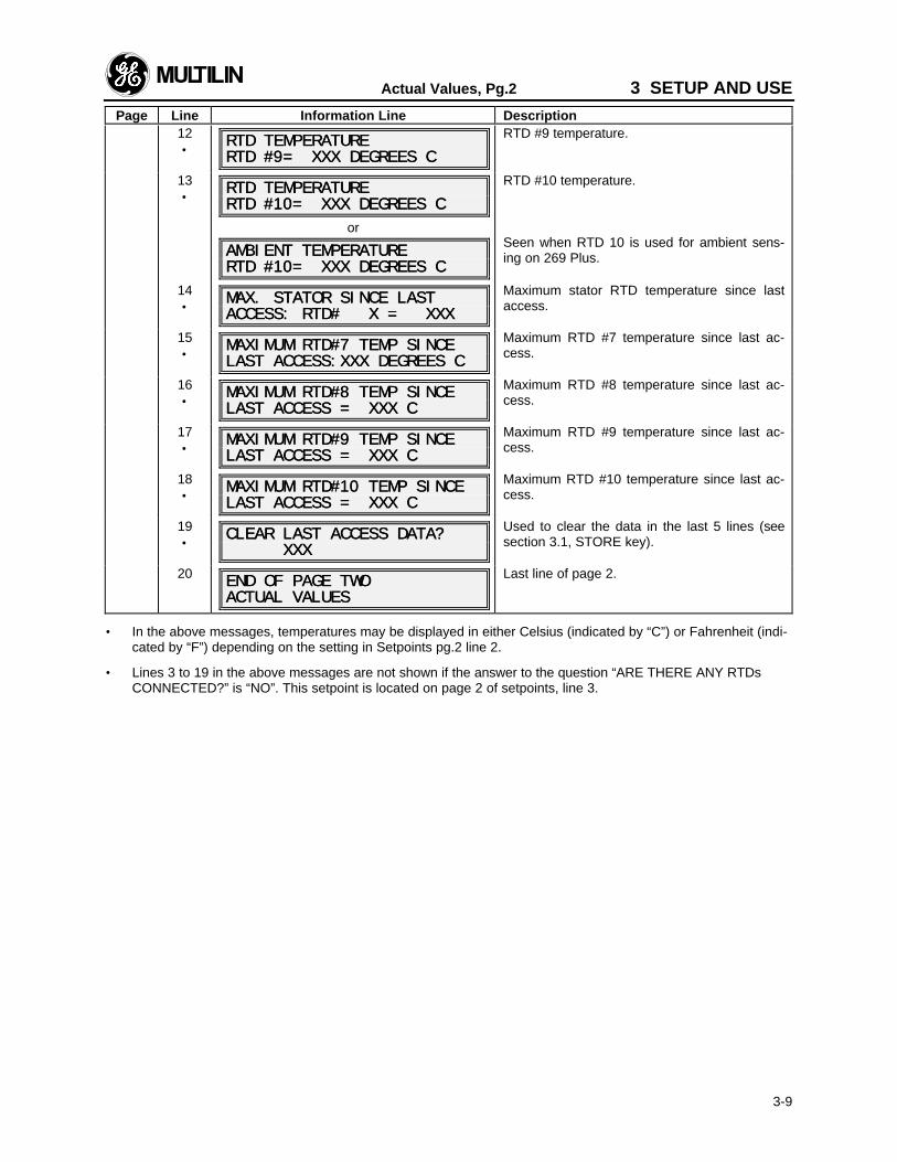
Actual Values, Pg.2 3 SETUP AND USE
Page Line Information Line Description
3-9
12•
RTD TEMPERATURERTD TEMPERATURERTD #9= XXX DEGREES CRTD #9= XXX DEGREES C
RTD #9 temperature.
13•
RTD TEMPERATURERTD TEMPERATURERTD #10= XXX DEGREES CRTD #10= XXX DEGREES C
or
AMBIENT TEMPERATUREAMBIENT TEMPERATURERTD #10= XXX DEGREES CRTD #10= XXX DEGREES C
RTD #10 temperature.
Seen when RTD 10 is used for ambient sens-ing on 269 Plus.
14•
MAX. STATOR SINCE LASTMAX. STATOR SINCE LASTACCESS: RTD# X = XXXACCESS: RTD# X = XXX
Maximum stator RTD temperature since lastaccess.
15•
MAXIMUM RTD#7 TEMP SINCEMAXIMUM RTD#7 TEMP SINCELAST ACCESS:XXX DEGREES CLAST ACCESS:XXX DEGREES C
Maximum RTD #7 temperature since last ac-cess.
16•
MAXIMUM RTD#8 TEMP SINCEMAXIMUM RTD#8 TEMP SINCELAST ACCESS = XXX CLAST ACCESS = XXX C
Maximum RTD #8 temperature since last ac-cess.
17•
MAXIMUM RTD#9 TEMP SINCEMAXIMUM RTD#9 TEMP SINCELAST ACCESS = XXX CLAST ACCESS = XXX C
Maximum RTD #9 temperature since last ac-cess.
18•
MAXIMUM RTD#10 TEMP SINCEMAXIMUM RTD#10 TEMP SINCELAST ACCESS = XXX CLAST ACCESS = XXX C
Maximum RTD #10 temperature since last ac-cess.
19•
CLEAR LAST ACCESS DATA?CLEAR LAST ACCESS DATA? XXX XXX
Used to clear the data in the last 5 lines (seesection 3.1, STORE key).
20END OF PAGE TWOEND OF PAGE TWOACTUAL VALUESACTUAL VALUES
Last line of page 2.
• In the above messages, temperatures may be displayed in either Celsius (indicated by “C”) or Fahrenheit (indi-cated by “F”) depending on the setting in Setpoints pg.2 line 2.
• Lines 3 to 19 in the above messages are not shown if the answer to the question “ARE THERE ANY RTDsCONNECTED?” is “NO”. This setpoint is located on page 2 of setpoints, line 3.
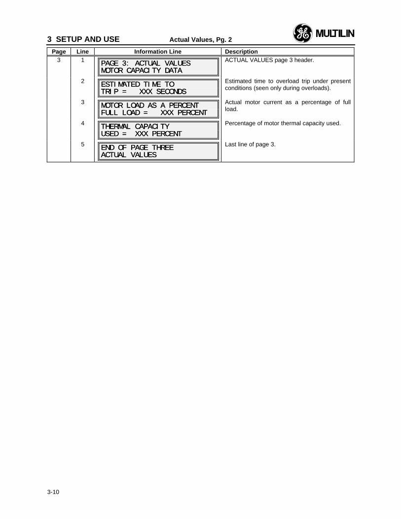
3 SETUP AND USE Actual Values, Pg. 2
Page Line Information Line Description
3-10
3 1 PAGE 3: ACTUAL VALUESPAGE 3: ACTUAL VALUESMOTOR CAPACITY DATAMOTOR CAPACITY DATA
ACTUAL VALUES page 3 header.
2 ESTIMATED TIME TOESTIMATED TIME TOTRIP = XXX SECONDSTRIP = XXX SECONDS
Estimated time to overload trip under presentconditions (seen only during overloads).
3MOTOR LOAD AS A PERCENTMOTOR LOAD AS A PERCENTFULL LOAD = XXX PERCENTFULL LOAD = XXX PERCENT
Actual motor current as a percentage of fullload.
4 THERMAL CAPACITYTHERMAL CAPACITYUSED = XXX PERCENTUSED = XXX PERCENT
Percentage of motor thermal capacity used.
5END OF PAGE THREEEND OF PAGE THREEACTUAL VALUESACTUAL VALUES
Last line of page 3.
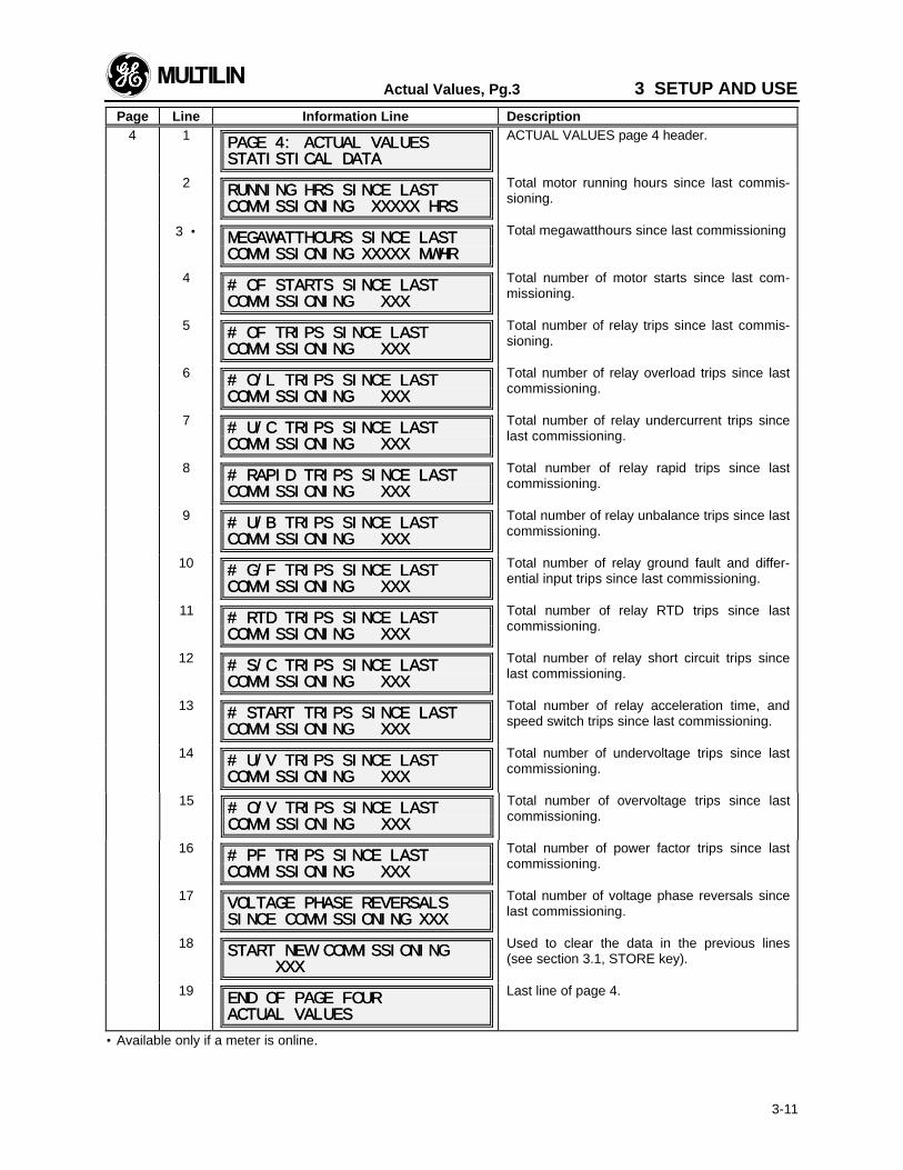
Actual Values, Pg.3 3 SETUP AND USE
Page Line Information Line Description
3-11
4 1 PAGE 4: ACTUAL VALUESPAGE 4: ACTUAL VALUESSTATISTICAL DATASTATISTICAL DATA
ACTUAL VALUES page 4 header.
2 RUNNING HRS SINCE LASTRUNNING HRS SINCE LASTCOMMISSIONING XXXXX HRSCOMMISSIONING XXXXX HRS
Total motor running hours since last commis-sioning.
3 • MEGAWATTHOURS SINCE LASTMEGAWATTHOURS SINCE LASTCOMMISSIONING XXXXX MWHRCOMMISSIONING XXXXX MWHR
Total megawatthours since last commissioning
4 # OF STARTS SINCE LAST# OF STARTS SINCE LASTCOMMISSIONING XXXCOMMISSIONING XXX
Total number of motor starts since last com-missioning.
5# OF TRIPS SINCE LAST# OF TRIPS SINCE LASTCOMMISSIONING XXXCOMMISSIONING XXX
Total number of relay trips since last commis-sioning.
6# O/L TRIPS SINCE LAST# O/L TRIPS SINCE LASTCOMMISSIONING XXXCOMMISSIONING XXX
Total number of relay overload trips since lastcommissioning.
7 # U/C TRIPS SINCE LAST# U/C TRIPS SINCE LASTCOMMISSIONING XXXCOMMISSIONING XXX
Total number of relay undercurrent trips sincelast commissioning.
8 # RAPID TRIPS SINCE LAST# RAPID TRIPS SINCE LASTCOMMISSIONING XXXCOMMISSIONING XXX
Total number of relay rapid trips since lastcommissioning.
9# U/B TRIPS SINCE LAST# U/B TRIPS SINCE LASTCOMMISSIONING XXXCOMMISSIONING XXX
Total number of relay unbalance trips since lastcommissioning.
10# G/F TRIPS SINCE LAST# G/F TRIPS SINCE LASTCOMMISSIONING XXXCOMMISSIONING XXX
Total number of relay ground fault and differ-ential input trips since last commissioning.
11# RTD TRIPS SINCE LAST# RTD TRIPS SINCE LASTCOMMISSIONING XXXCOMMISSIONING XXX
Total number of relay RTD trips since lastcommissioning.
12 # S/C TRIPS SINCE LAST# S/C TRIPS SINCE LASTCOMMISSIONING XXXCOMMISSIONING XXX
Total number of relay short circuit trips sincelast commissioning.
13 # START TRIPS SINCE LAST# START TRIPS SINCE LASTCOMMISSIONING XXXCOMMISSIONING XXX
Total number of relay acceleration time, andspeed switch trips since last commissioning.
14 # U/V TRIPS SINCE LAST# U/V TRIPS SINCE LASTCOMMISSIONING XXXCOMMISSIONING XXX
Total number of undervoltage trips since lastcommissioning.
15 # O/V TRIPS SINCE LAST# O/V TRIPS SINCE LASTCOMMISSIONING XXXCOMMISSIONING XXX
Total number of overvoltage trips since lastcommissioning.
16 # PF TRIPS SINCE LAST# PF TRIPS SINCE LASTCOMMISSIONING XXXCOMMISSIONING XXX
Total number of power factor trips since lastcommissioning.
17 VOLTAGE PHASE REVERSALSVOLTAGE PHASE REVERSALSSINCE COMMISSIONING XXXSINCE COMMISSIONING XXX
Total number of voltage phase reversals sincelast commissioning.
18 START NEW COMMISSIONINGSTART NEW COMMISSIONING XXX XXX
Used to clear the data in the previous lines(see section 3.1, STORE key).
19 END OF PAGE FOUREND OF PAGE FOURACTUAL VALUESACTUAL VALUES
Last line of page 4.
• Available only if a meter is online.
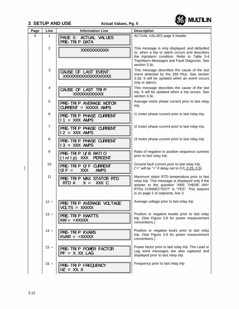
3 SETUP AND USE Actual Values, Pg. 5
Page Line Information Line Description
3-12
5 1 PAGE 5: ACTUAL VALUESPAGE 5: ACTUAL VALUESPRE-TRIP DATAPRE-TRIP DATA
ACTUAL VALUES page 5 header.
2 XXXXXXXXXXXXXXXXXXXXXX This message is only displayed, and defaultedto, when a trip or alarm occurs and describesthe trip/alarm condition. Refer to Table 3-4Trip/Alarm Messages and Fault Diagnosis. Seesection 3.3c.
3CAUSE OF LAST EVENT:CAUSE OF LAST EVENT: XXXXXXXXXXXXXXXXXXX XXXXXXXXXXXXXXXXXXX
This message describes the cause of the lastevent detected by the 269 Plus. See section3.3d. It will be updated when an event occurs(trip or alarm).
4CAUSE OF LAST TRIP:CAUSE OF LAST TRIP: XXXXXXXXXXXX XXXXXXXXXXXX
This message describes the cause of the lasttrip. It will be updated when a trip occurs. Seesection 3.3c.
5PRE-TRIP AVERAGE MOTORPRE-TRIP AVERAGE MOTORCURRENT = XXXXX AMPSCURRENT = XXXXX AMPS
Average motor phase current prior to last relaytrip.
6 PRE-TRIP PHASE CURRENTPRE-TRIP PHASE CURRENTI1 = XXX AMPSI1 = XXX AMPS
I1 motor phase current prior to last relay trip.
7PRE-TRIP PHASE CURRENTPRE-TRIP PHASE CURRENTI2 = XXX AMPSI2 = XXX AMPS
I2 motor phase current prior to last relay trip.
8PRE-TRIP PHASE CURRENTPRE-TRIP PHASE CURRENTI3 = XXX AMPSI3 = XXX AMPS
I3 motor phase current prior to last relay trip.
9PRE-TRIP U/B RATIOPRE-TRIP U/B RATIO(In/(In/Ip) XXX PERCENTIp) XXX PERCENT
Ratio of negative to positive sequence currentsprior to last relay trip.
10 PRE-TRIP G/F CURRENTPRE-TRIP G/F CURRENTG/F = XXX AMPSG/F = XXX AMPS
Ground fault current prior to last relay trip.("=" will be ">" if delay set to 0.0, 0.25, 0.5)
11 PRE-TRIP MAX STATOR RTDPRE-TRIP MAX STATOR RTD RTD # X = XXX C RTD # X = XXX C
Maximum stator RTD temperature prior to lastrelay trip. This message is displayed only if theanswer to the question “ARE THERE ANYRTDs CONNECTED?” is “YES”. This setpointis on page 2 of setpoints, line 3.
12 • PRE-TRIP AVERAGE VOLTAGEPRE-TRIP AVERAGE VOLTAGEVOLTS = XXXXXVOLTS = XXXXX
Average voltage prior to last relay trip
13 • PRE-TRIP PRE-TRIP KWATTSKWATTSKW = +XXXXXKW = +XXXXX
Positive or negative kwatts prior to last relaytrip. (See Figure 3.8 for power measurementconventions.)
14 • PRE-TRIP PRE-TRIP KVARSKVARSKVAR = +XXXXXKVAR = +XXXXX
Positive or negative kvars prior to last relaytrip. (See Figure 3.8 for power measurementconventions.)
15 • PRE-TRIP POWER FACTORPRE-TRIP POWER FACTORPF = X.XX LAGPF = X.XX LAG
Power factor prior to last relay trip. The Lead orLag word messages are also captured anddisplayed prior to last relay trip.
16 • PRE-TRIP FREQUENCYPRE-TRIP FREQUENCYHZ = XX.XHZ = XX.X
Frequency prior to last relay trip
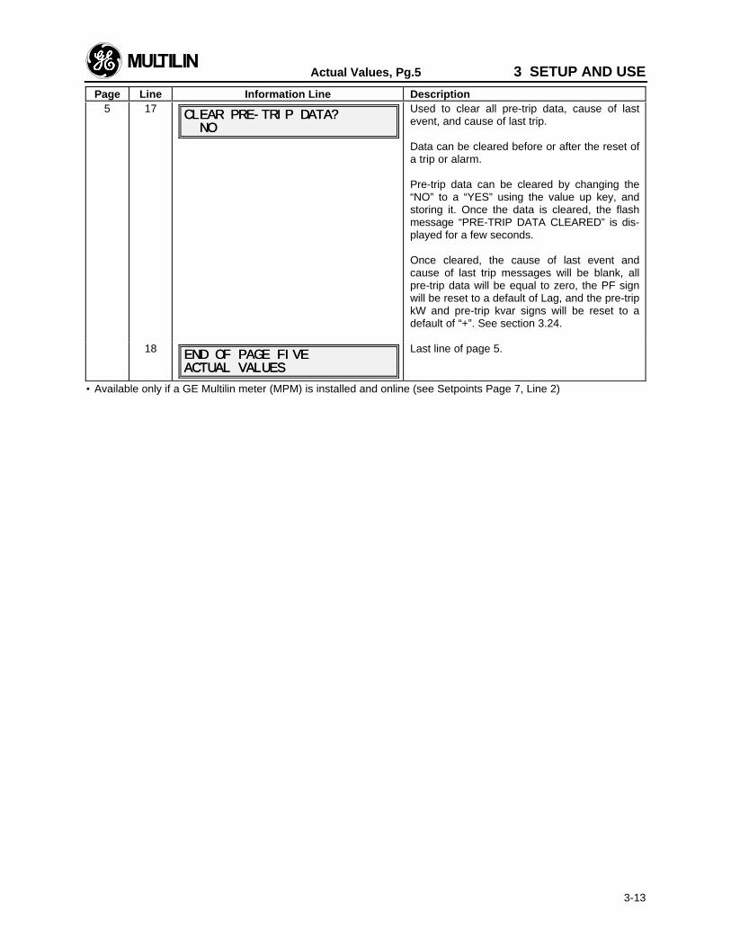
Actual Values, Pg.5 3 SETUP AND USE
Page Line Information Line Description
3-13
5 17 CLEAR PRE-TRIP DATA?CLEAR PRE-TRIP DATA? NO NO
Used to clear all pre-trip data, cause of lastevent, and cause of last trip.
Data can be cleared before or after the reset ofa trip or alarm.
Pre-trip data can be cleared by changing the“NO” to a “YES” using the value up key, andstoring it. Once the data is cleared, the flashmessage “PRE-TRIP DATA CLEARED” is dis-played for a few seconds.
Once cleared, the cause of last event andcause of last trip messages will be blank, allpre-trip data will be equal to zero, the PF signwill be reset to a default of Lag, and the pre-tripkW and pre-trip kvar signs will be reset to adefault of “+”. See section 3.24.
18 END OF PAGE FIVEEND OF PAGE FIVEACTUAL VALUESACTUAL VALUES
Last line of page 5.
• Available only if a GE Multilin meter (MPM) is installed and online (see Setpoints Page 7, Line 2)
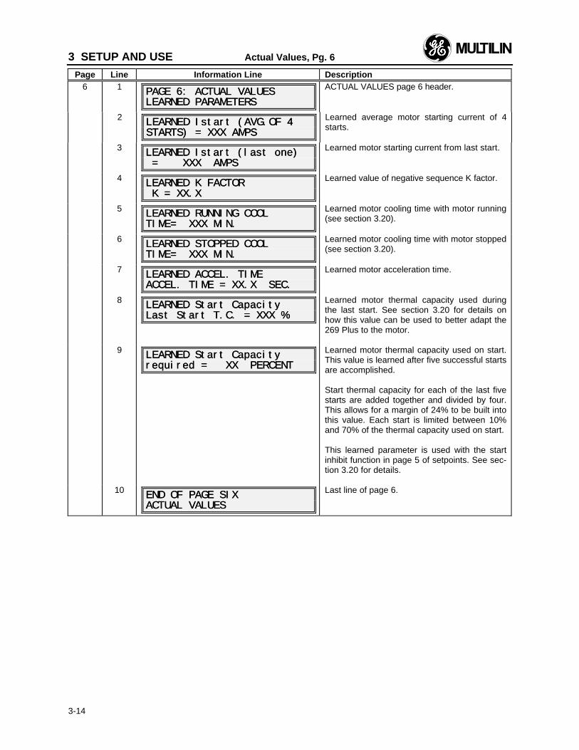
3 SETUP AND USE Actual Values, Pg. 6
Page Line Information Line Description
3-14
6 1 PAGE 6: ACTUAL VALUESPAGE 6: ACTUAL VALUESLEARNED PARAMETERSLEARNED PARAMETERS
ACTUAL VALUES page 6 header.
2 LEARNED LEARNED Istart (AVG.OF 4Istart (AVG.OF 4STARTS) = XXX AMPSSTARTS) = XXX AMPS
Learned average motor starting current of 4starts.
3LEARNED LEARNED Istart (last one)Istart (last one) = XXX AMPS = XXX AMPS
Learned motor starting current from last start.
4 LEARNED K FACTORLEARNED K FACTOR K = XX.X K = XX.X
Learned value of negative sequence K factor.
5LEARNED RUNNING COOLLEARNED RUNNING COOLTIMETIME= XXX MIN.= XXX MIN.
Learned motor cooling time with motor running(see section 3.20).
6LEARNED STOPPED COOLLEARNED STOPPED COOLTIMETIME= XXX MIN.= XXX MIN.
Learned motor cooling time with motor stopped(see section 3.20).
7 LEARNED ACCEL. TIMELEARNED ACCEL. TIMEACCEL. TIME = ACCEL. TIME = XX.X SEC.XX.X SEC.
Learned motor acceleration time.
8 LEARNED Start CapacityLEARNED Start CapacityLast Start T.C. = XXX %Last Start T.C. = XXX %
Learned motor thermal capacity used duringthe last start. See section 3.20 for details onhow this value can be used to better adapt the269 Plus to the motor.
9 LEARNED Start CapacityLEARNED Start Capacityrequired = XX PERCENTrequired = XX PERCENT
Learned motor thermal capacity used on start.This value is learned after five successful startsare accomplished.
Start thermal capacity for each of the last fivestarts are added together and divided by four.This allows for a margin of 24% to be built intothis value. Each start is limited between 10%and 70% of the thermal capacity used on start.
This learned parameter is used with the startinhibit function in page 5 of setpoints. See sec-tion 3.20 for details.
10 END OF PAGE SIXEND OF PAGE SIXACTUAL VALUESACTUAL VALUES
Last line of page 6.
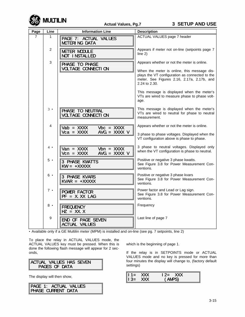
Actual Values, Pg.7 3 SETUP AND USE
Page Line Information Line Description
3-15
7 1 PAGE 7: ACTUAL VALUESPAGE 7: ACTUAL VALUESMETERING DATAMETERING DATA
ACTUAL VALUES page 7 header
2 METER MODULEMETER MODULENOT INSTALLEDNOT INSTALLED
Appears if meter not on-line (setpoints page 7line 2)
3PHASE TO PHASEPHASE TO PHASEVOLTAGE CONNECTIONVOLTAGE CONNECTION
Appears whether or not the meter is online.
When the meter is online, this message dis-plays the VT configuration as connected to themeter. See Figures 2.16, 2.17a, 2.17b, and2.24 to 2.30.
This message is displayed when the meter’sVTs are wired to measure phase to phase volt-age.
3 • PHASE TO NEUTRALPHASE TO NEUTRALVOLTAGE CONNECTIONVOLTAGE CONNECTION
This message is displayed when the meter’sVTs are wired to neutral for phase to neutralmeasurement.
4Vab = XXXX Vab = XXXX Vbc = XXXXVbc = XXXXVca = XXXX AVG.= XXXX VVca = XXXX AVG.= XXXX V
Appears whether or not the meter is online.
3 phase to phase voltages. Displayed when theVT configuration above is phase to phase.
4 • Van = XXXX Van = XXXX Vbn = XXXXVbn = XXXXVcn = XXXX AVG.= XXXX VVcn = XXXX AVG.= XXXX V
3 phase to neutral voltages. Displayed onlywhen the VT configuration is phase to neutral.
5 • 3 PHASE 3 PHASE KWATTSKWATTSKW = +XXXXXKW = +XXXXX
Positive or negative 3 phase kwatts.See Figure 3.8 for Power Measurement Con-ventions.
6 • 3 PHASE 3 PHASE KVARSKVARSKVAR = +XXXXXKVAR = +XXXXX
Positive or negative 3 phase kvarsSee Figure 3.8 for Power Measurement Con-ventions.
7 • POWER FACTORPOWER FACTORPF = X.XX LAGPF = X.XX LAG
Power factor and Lead or Lag sign.See Figure 3.8 for Power Measurement Con-ventions.
8 • FREQUENCYFREQUENCYHZ = XX.XHZ = XX.X
Frequency
9 END OF PAGE SEVENEND OF PAGE SEVENACTUAL VALUESACTUAL VALUES
Last line of page 7
• Available only if a GE Multilin meter (MPM) is installed and on-line (see pg. 7 setpoints, line 2)
To place the relay in ACTUAL VALUES mode, theACTUAL VALUES key must be pressed. When this isdone the following flash message will appear for 2 sec-onds,
ACTUAL VALUES HAS SEVENACTUAL VALUES HAS SEVEN PAGES OF DATA PAGES OF DATA
The display will then show,
PAGE 1: ACTUAL VALUESPAGE 1: ACTUAL VALUESPHASE CURRENT DATAPHASE CURRENT DATA
which is the beginning of page 1.
If the relay is in SETPOINTS mode or ACTUALVALUES mode and no key is pressed for more thanfour minutes the display will change to, (factory defaultsettings)
I1I1= XXX I2= XXX= XXX I2= XXXI3= XXX (AMPS)I3= XXX (AMPS)
3 SETUP AND USE
3-16
which is the second line in page 1 of ACTUAL VALUESmode. This default display line can be changed inpage 5 of SETPOINTS mode.
When in this mode the PAGE UP, PAGE DOWN, LINEUP, and LINE DOWN keys (see section 3.1) can beused to examine all of the actual motor data outlinedabove.
3.3a Starts/Hour Timer
An individual starts/hour timer is activated each time amotor start condition is detected and starts to time outbeginning from 60 minutes. All starts/hour timers canbe viewed in Actual Values pg. 1 line 7. If the number ofstarts/hour programmed in SETPOINTS pg.1 line 7 isexceeded within one hour, a start/hour inhibit is initiatedwith a lockout time equal to the smallest start/hourtimer. A maximum of five starts/hour may be pro-grammed, or the setpoint turned OFF.
In the case of an emergency, when the lockout time hasto be bypassed and an additional start is required, theEmergency Restart button can be pushed (terminals#54 and 55 temporarily shorted) making the smalleststart/hour timer zero, resetting the inhibit and effectivelyallowing an additional start. Note that the other timerscontinue to time out unaffected.
Every time the Emergency Restart button is pushed,another timer is emptied and an additional start/hour isallowed. For example, pushing the Emergency Restartbutton again will empty the second timer and two morestarts/hour are allowed before another start/hour inhibitis initiated.
3.3b Time Between Starts Timer
This timer corresponds to the “Time Between StartsTime Delay” feature in Setpoints pg. 5 line 36. The timedisplayed is the actual lockout time that the user has towait before an additional start can be performed.
This timer is updated continuously until it expires, thena zero is displayed. When the timer expires, this indi-cates to the user that a start is allowed immediatelyafter a motor stop without any lockout time.
The time between starts timer is equal to zero in thefollowing two cases:
1. If the timer has expired and therefore there’s nolockout time prior to starting again after a motorstop condition is detected.
2. If the “Time Between Starts Time Delay” featureis set to “OFF” in SETPOINTS page 5 line 36.
3.3c Cause of Last Trip
The message in Actual Values pg.5 line 3 describes thecause of the last trip. It will be updated when a trip oc-curs. “XXXXXXXXXXX” in the message represents oneof the following trips:
Overload trip Speed Switch tripShort Circuit trip Differential tripRapid Trip Single Phase tripStator RTD trip Spare Input tripRTD trip Power Factor tripGround Fault trip Undervoltage tripAcceleration trip Overvoltage tripPhase Reversal trip Undercurrent trip
3.3d Cause of Last Event
An event is defined as a TRIP or an INHIBIT. If the lastevent was a trip, then the message “CAUSE OF LASTEVENT” and the following message “CAUSE OF LASTTRIP” are the same, mainly displaying the cause of thetrip. However, it is possible to have a trip which is im-mediately followed by an inhibit such as starts/hour,time between starts, start inhibit or backspin timer. Inthis case, “INHIBIT LOCKOUT” is displayed as the“CAUSE OF LAST EVENT” message and the cause ofthe trip is displayed as the “CAUSE OF LAST TRIP”message. Sometimes only an inhibit activates theTRIP, AUX1 or TRIP and AUX1 relays. This may hap-pen when the motor is intentionally stopped, but moreoften, it happens accidentally on an unloaded motorwhen current drops below 5% of CT. 5% of CT is thecutoff point for the 269 Plus, where a motor stop condi-tion is registered. In this case, the cause of the last tripis not updated. Only the cause of last event message isupdated to show “INHIBIT LOCKOUT”. This messageshould greatly assist in the diagnosis of the problem,because the activation of the TRIP relay will not bemisunderstood and treated as an actual trip. Instead,the solution may be fairly simple to implement, and itmay only require that a 52b contact for a breaker, orequivalent for a contactor, be wired to terminals 44 and45 on the 269 Plus, and the setpoint “SPARE INPUTTO READ 52b?” on page 5 of setpoints be changed to
3.4 SETPOINTS Mode
In SETPOINTS mode any or all of the motor trip/alarmsetpoints may be either viewed or altered. This mode isdivided into seven separate pages of data each ofwhich contains a different group of relay setpoints.
To enter SETPOINTS mode the SET POINTS key mustbe pressed. When in this mode, if no key is pressedfor more than four minutes, the display will automati-cally go into ACTUAL VALUES mode as explained insection 3.3. To return to SETPOINTS mode the SET
3 SETUP AND USE
3-17
POINTS key must be pressed. When this key ispressed the following flash message will appear on thedisplay,
SETPOINTS HAS SEVENSETPOINTS HAS SEVEN PAGES OF DATA PAGES OF DATA
Then the display will show,
PAGE 1: SETPOINT VALUESPAGE 1: SETPOINT VALUESMOTOR AMPS SETPOINTSMOTOR AMPS SETPOINTS
which is the first line of the first page of SETPOINTSmode. The PAGE UP, PAGE DOWN, LINE UP, andLINE DOWN keys (see section 3.1) may then be usedto view all of the SETPOINTS data.
When setpoints are to be changed, the VALUE UP,VALUE DOWN, STORE, and CLEAR keys (see section3.1) are used. The Access terminals must first beshorted together (see section 2.17). The PAGE UP,PAGE DOWN, LINE UP, and LINE DOWN keys areused to display the setpoints that are to be changed.The setpoints themselves are changed by pressing theVALUE UP or VALUE DOWN keys until the desiredsetpoint value is reached. To return the setpoint to itsoriginal value, the CLEAR key can be used. When thesetpoint is adjusted to its proper value the STORE keyshould be pressed in order to store the setpoint into the269 Plus' internal memory. Once the STORE key ispressed the flash message,
new setpoint storednew setpoint stored
will appear on the display and the new setpoint valuewill be used by the 269 Plus relay.
If an attempt is made to store a new setpoint valuewithout the Access terminals shorted together the newvalue will not be stored and the flash message,
ILLEGAL ACCESS ILLEGAL ACCESS
will appear on the display. To make the setpoints tam-perproof the Access terminals should be shorted to-gether only when setpoints are to be changed.
Setpoints may be changed while the motor is running;however it is not recommended to change importantprotection parameters without first stopping the motor.
Setpoints will remain stored indefinitely in the 269 Plusrelay's internal non-volatile memory even when controlpower to the unit is removed.
All seven pages of data and the lines in each page areas shown in Table 3-3. Also shown are the default set-
tings, ranges and increments for each setpoint. Itshould be noted that the 269 Plus relay's motor protec-tion parameters are based on the data entered by theuser. Thus this data must be complete and accuratefor the given system.
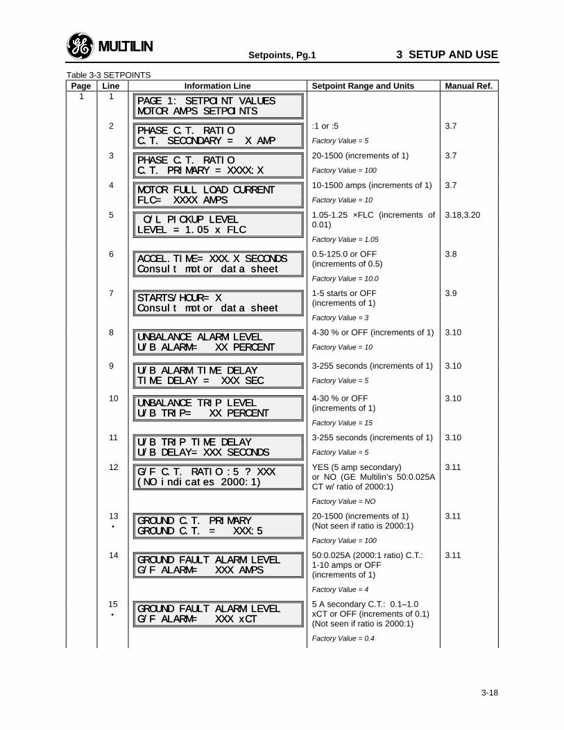
Setpoints, Pg.1 3 SETUP AND USE
3-18
Table 3-3 SETPOINTSPage Line Information Line Setpoint Range and Units Manual Ref.
1 1PAGE 1: SETPOINT VALUESPAGE 1: SETPOINT VALUESMOTOR AMPS SETPOINTSMOTOR AMPS SETPOINTS
2PHASE PHASE C.T. RATIOC.T. RATIOC.T. SECONDARY = X AMPC.T. SECONDARY = X AMP
:1 or :5
Factory Value = 5
3.7
3 PHASE PHASE C.T. RATIOC.T. RATIOC.T. PRIMARY = XXXX:XC.T. PRIMARY = XXXX:X
20-1500 (increments of 1)
Factory Value = 100
3.7
4MOTOR FULL LOAD CURRENTMOTOR FULL LOAD CURRENTFLC= XXXX AMPSFLC= XXXX AMPS
10-1500 amps (increments of 1)
Factory Value = 10
3.7
5 O/L PICKUP LEVEL O/L PICKUP LEVELLEVEL = 1.05 x FLCLEVEL = 1.05 x FLC
1.05-1.25 ×FLC (increments of0.01)
Factory Value = 1.05
3.18,3.20
6 ACCEL.TIME= XXX.X SECONDSACCEL.TIME= XXX.X SECONDSConsult motor data sheetConsult motor data sheet
0.5-125.0 or OFF(increments of 0.5)
Factory Value = 10.0
3.8
7STARTS/HOUR= XSTARTS/HOUR= XConsult motor data sheetConsult motor data sheet
1-5 starts or OFF(increments of 1)
Factory Value = 3
3.9
8 UNBALANCE ALARM LEVELUNBALANCE ALARM LEVELU/B ALARM= XX PERCENTU/B ALARM= XX PERCENT
4-30 % or OFF (increments of 1)
Factory Value = 10
3.10
9U/B ALARM TIME DELAYU/B ALARM TIME DELAYTIME DELAY = XXX SECTIME DELAY = XXX SEC
3-255 seconds (increments of 1)
Factory Value = 5
3.10
10UNBALANCE TRIP LEVELUNBALANCE TRIP LEVELU/B TRIP= XX PERCENTU/B TRIP= XX PERCENT
4-30 % or OFF(increments of 1)
Factory Value = 15
3.10
11 U/B TRIP TIME DELAYU/B TRIP TIME DELAYU/B DELAY= XXX SECONDSU/B DELAY= XXX SECONDS
3-255 seconds (increments of 1)
Factory Value = 5
3.10
12G/F G/F C.T. C.T. RATIO :5 ? XXXRATIO :5 ? XXX(NO indicates 2000:1)(NO indicates 2000:1)
YES (5 amp secondary)or NO (GE Multilin’s 50:0.025ACT w/ ratio of 2000:1)
Factory Value = NO
3.11
13•
GROUND GROUND C.T. PRIMARYC.T. PRIMARYGROUND GROUND C.T. = XXX:5C.T. = XXX:5
20-1500 (increments of 1)(Not seen if ratio is 2000:1)
Factory Value = 100
3.11
14 GROUND FAULT ALARM LEVELGROUND FAULT ALARM LEVELG/F ALARM= XXX AMPSG/F ALARM= XXX AMPS
50:0.025A (2000:1 ratio) C.T.:1-10 amps or OFF(increments of 1)
Factory Value = 4
3.11
15•
GROUND FAULT ALARM LEVELGROUND FAULT ALARM LEVELG/F ALARM= XXX G/F ALARM= XXX xCTxCT
5 A secondary C.T.: 0.1–1.0xCT or OFF (increments of 0.1)(Not seen if ratio is 2000:1)
Factory Value = 0.4
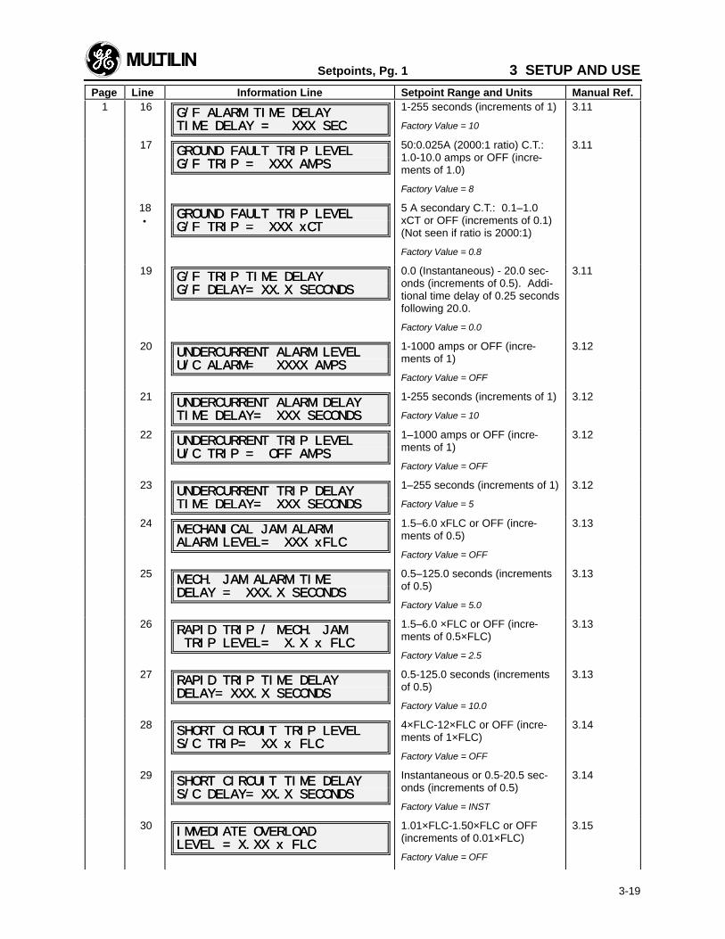
Setpoints, Pg. 1 3 SETUP AND USE
Page Line Information Line Setpoint Range and Units Manual Ref.
3-19
1 16G/F ALARM TIME DELAYG/F ALARM TIME DELAYTIME DELAY = XXX SECTIME DELAY = XXX SEC
1-255 seconds (increments of 1)
Factory Value = 10
3.11
17 GROUND FAULT TRIP LEVELGROUND FAULT TRIP LEVELG/F TRIP = XXX AMPSG/F TRIP = XXX AMPS
50:0.025A (2000:1 ratio) C.T.:1.0-10.0 amps or OFF (incre-ments of 1.0)
Factory Value = 8
3.11
18•
GROUND FAULT TRIP LEVELGROUND FAULT TRIP LEVELG/F TRIP = XXX G/F TRIP = XXX xCTxCT
5 A secondary C.T.: 0.1–1.0xCT or OFF (increments of 0.1)(Not seen if ratio is 2000:1)
Factory Value = 0.8
19G/F TRIP TIME DELAYG/F TRIP TIME DELAYG/F DELAY= XX.X SECONDSG/F DELAY= XX.X SECONDS
0.0 (Instantaneous) - 20.0 sec-onds (increments of 0.5). Addi-tional time delay of 0.25 secondsfollowing 20.0.
Factory Value = 0.0
3.11
20 UNDERCURRENT ALARM LEVELUNDERCURRENT ALARM LEVELU/C ALARM= XXXX AMPSU/C ALARM= XXXX AMPS
1-1000 amps or OFF (incre-ments of 1)
Factory Value = OFF
3.12
21UNDERCURRENT ALARM DELAYUNDERCURRENT ALARM DELAYTIME DELAY= XXX SECONDSTIME DELAY= XXX SECONDS
1-255 seconds (increments of 1)
Factory Value = 10
3.12
22 UNDERCURRENT TRIP LEVELUNDERCURRENT TRIP LEVELU/C TRIP = OFF AMPSU/C TRIP = OFF AMPS
1–1000 amps or OFF (incre-ments of 1)
Factory Value = OFF
3.12
23 UNDERCURRENT TRIP DELAYUNDERCURRENT TRIP DELAYTIME DELAY= XXX SECONDSTIME DELAY= XXX SECONDS
1–255 seconds (increments of 1)
Factory Value = 5
3.12
24 MECHANICAL JAM ALARMMECHANICAL JAM ALARMALARM LEVEL= XXX ALARM LEVEL= XXX xFLCxFLC
1.5–6.0 xFLC or OFF (incre-ments of 0.5)
Factory Value = OFF
3.13
25MECH. JAM ALARM TIMEMECH. JAM ALARM TIMEDELAY = XXX.X SECONDSDELAY = XXX.X SECONDS
0.5–125.0 seconds (incrementsof 0.5)
Factory Value = 5.0
3.13
26 RAPID TRIP / MECH. JAMRAPID TRIP / MECH. JAM TRIP LEVEL= X.X x FLC TRIP LEVEL= X.X x FLC
1.5–6.0 ×FLC or OFF (incre-ments of 0.5×FLC)
Factory Value = 2.5
3.13
27 RAPID TRIP TIME DELAYRAPID TRIP TIME DELAYDELAY= XXX.X SECONDSDELAY= XXX.X SECONDS
0.5-125.0 seconds (incrementsof 0.5)
Factory Value = 10.0
3.13
28 SHORT CIRCUIT TRIP LEVELSHORT CIRCUIT TRIP LEVELS/C TRIP= XX x FLCS/C TRIP= XX x FLC
4×FLC-12×FLC or OFF (incre-ments of 1×FLC)
Factory Value = OFF
3.14
29 SHORT CIRCUIT TIME DELAYSHORT CIRCUIT TIME DELAYS/C DELAY= XX.X SECONDSS/C DELAY= XX.X SECONDS
Instantaneous or 0.5-20.5 sec-onds (increments of 0.5)
Factory Value = INST
3.14
30 IMMEDIATE OVERLOADIMMEDIATE OVERLOADLEVEL = X.XX x FLCLEVEL = X.XX x FLC
1.01×FLC-1.50×FLC or OFF(increments of 0.01×FLC)
Factory Value = OFF
3.15

3 SETUP AND USE Setpoints, Pg. 1
Page Line Information Line Setpoint Range and Units Manual Ref.
3-20
31END OF PAGE ONEEND OF PAGE ONESETPOINT VALUESSETPOINT VALUES
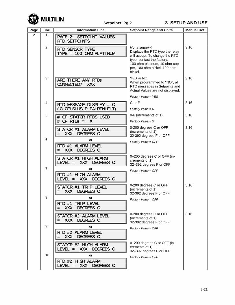
Setpoints, Pg.2 3 SETUP AND USE
Page Line Information Line Setpoint Range and Units Manual Ref.
3-21
2 1 PAGE 2: SETPOINT VALUESPAGE 2: SETPOINT VALUESRTD SETPOINTSRTD SETPOINTS
2RTD SENSOR TYPERTD SENSOR TYPETYPE = 100 OHM PLATINUMTYPE = 100 OHM PLATINUM
Not a setpoint.Displays the RTD type the relaywill accept. To change the RTDtype, contact the factory.100 ohm platinum, 10 ohm cop-per, 100 ohm nickel, 120 ohmnickel.
3.16
3 ARE THERE ANY RTDsARE THERE ANY RTDsCONNECTED? XXXCONNECTED? XXX
YES or NOWhen programmed to "NO", allRTD messages in Setpoints andActual Values are not displayed.
Factory Value = YES
3.16
4RTD MESSAGE DISPLAY = CRTD MESSAGE DISPLAY = C(C:CELSIUS/F:FAHRENHEIT)(C:CELSIUS/F:FAHRENHEIT)
C or F
Factory Value = C
3.16
5 # OF STATOR # OF STATOR RTDS USEDRTDS USED# OF RTDs = X# OF RTDs = X
0-6 (increments of 1)
Factory Value = 6
3.16
6
STATOR #1 ALARM LEVELSTATOR #1 ALARM LEVEL= XXX DEGREES C= XXX DEGREES C
or
RTD #1 ALARM LEVELRTD #1 ALARM LEVEL= XXX DEGREES C= XXX DEGREES C
0-200 degrees C or OFF(increments of 1)32-392 degrees F or OFF
Factory Value = OFF
3.16
7
STATOR #1 HIGH ALARMSTATOR #1 HIGH ALARMLEVEL = XXX DEGREES CLEVEL = XXX DEGREES C
or
RTD #1 HIGH ALARMRTD #1 HIGH ALARMLEVEL = XXX DEGREES CLEVEL = XXX DEGREES C
0–200 degrees C or OFF (in-crements of 1)32–392 degrees F or OFF
Factory Value = OFF
8
STATOR #1 TRIP LEVELSTATOR #1 TRIP LEVEL= XXX DEGREES C= XXX DEGREES C
or
RTD #1 TRIP LEVELRTD #1 TRIP LEVEL= XXX DEGREES C= XXX DEGREES C
0-200 degrees C or OFF(increments of 1)32-392 degrees F or OFF
Factory Value = OFF
3.16
9
STATOR #2 ALARM LEVELSTATOR #2 ALARM LEVEL= XXX DEGREES C= XXX DEGREES C
or
RTD #2 ALARM LEVELRTD #2 ALARM LEVEL= XXX DEGREES C= XXX DEGREES C
0-200 degrees C or OFF(increments of 1)32-392 degrees F or OFF
Factory Value = OFF
3.16
10
STATOR #2 HIGH ALARMSTATOR #2 HIGH ALARMLEVEL = XXX DEGREES CLEVEL = XXX DEGREES C
or
RTD #2 HIGH ALARMRTD #2 HIGH ALARMLEVEL = XXX DEGREES CLEVEL = XXX DEGREES C
0–200 degrees C or OFF (in-crements of 1)32–392 degrees F or OFF
Factory Value = OFF
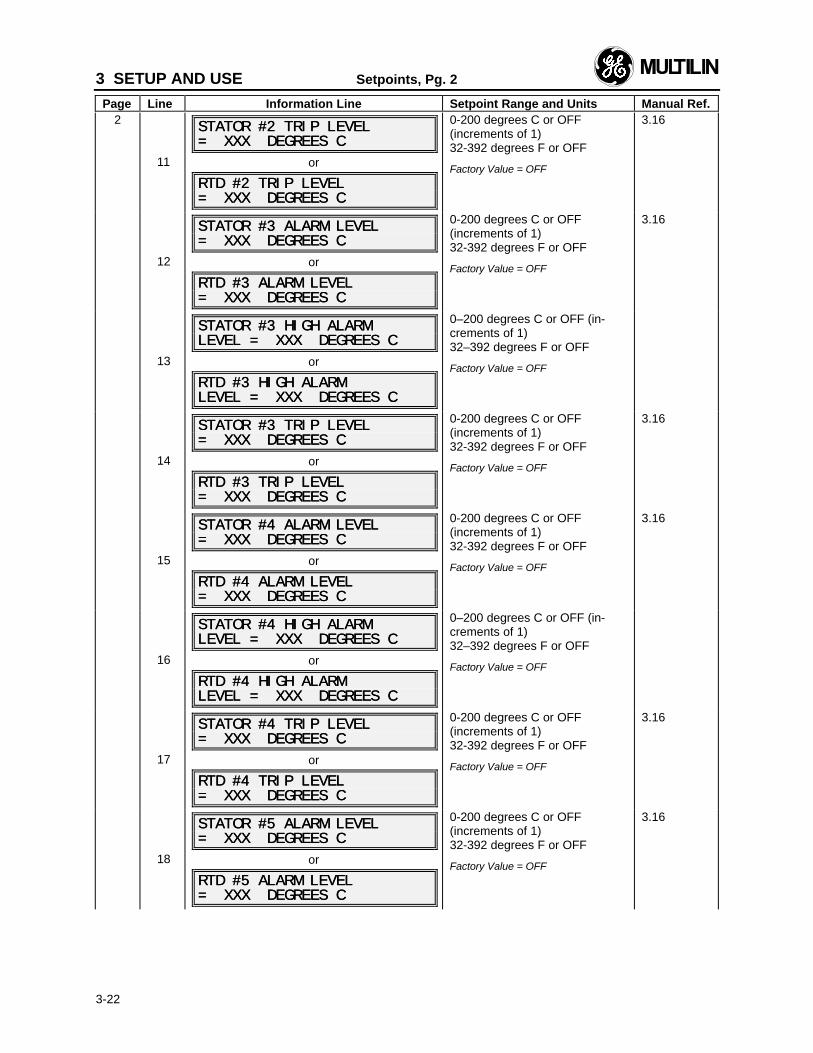
3 SETUP AND USE Setpoints, Pg. 2
Page Line Information Line Setpoint Range and Units Manual Ref.
3-22
2
11
STATOR #2 TRIP LEVELSTATOR #2 TRIP LEVEL= XXX DEGREES C= XXX DEGREES C
or
RTD #2 TRIP LEVELRTD #2 TRIP LEVEL= XXX DEGREES C= XXX DEGREES C
0-200 degrees C or OFF(increments of 1)32-392 degrees F or OFF
Factory Value = OFF
3.16
12
STATOR #3 ALARM LEVELSTATOR #3 ALARM LEVEL= XXX DEGREES C= XXX DEGREES C
or
RTD #3 ALARM LEVELRTD #3 ALARM LEVEL= XXX DEGREES C= XXX DEGREES C
0-200 degrees C or OFF(increments of 1)32-392 degrees F or OFF
Factory Value = OFF
3.16
13
STATOR #3 HIGH ALARMSTATOR #3 HIGH ALARMLEVEL = XXX DEGREES CLEVEL = XXX DEGREES C
or
RTD #3 HIGH ALARMRTD #3 HIGH ALARMLEVEL = XXX DEGREES CLEVEL = XXX DEGREES C
0–200 degrees C or OFF (in-crements of 1)32–392 degrees F or OFF
Factory Value = OFF
14
STATOR #3 TRIP LEVELSTATOR #3 TRIP LEVEL= XXX DEGREES C= XXX DEGREES C
or
RTD #3 TRIP LEVELRTD #3 TRIP LEVEL= XXX DEGREES C= XXX DEGREES C
0-200 degrees C or OFF(increments of 1)32-392 degrees F or OFF
Factory Value = OFF
3.16
15
STATOR #4 ALARM LEVELSTATOR #4 ALARM LEVEL= XXX DEGREES C= XXX DEGREES C
or
RTD #4 ALARM LEVELRTD #4 ALARM LEVEL= XXX DEGREES C= XXX DEGREES C
0-200 degrees C or OFF(increments of 1)32-392 degrees F or OFF
Factory Value = OFF
3.16
16
STATOR #4 HIGH ALARMSTATOR #4 HIGH ALARMLEVEL = XXX DEGREES CLEVEL = XXX DEGREES C
or
RTD #4 HIGH ALARMRTD #4 HIGH ALARMLEVEL = XXX DEGREES CLEVEL = XXX DEGREES C
0–200 degrees C or OFF (in-crements of 1)32–392 degrees F or OFF
Factory Value = OFF
17
STATOR #4 TRIP LEVELSTATOR #4 TRIP LEVEL= XXX DEGREES C= XXX DEGREES C
or
RTD #4 TRIP LEVELRTD #4 TRIP LEVEL= XXX DEGREES C= XXX DEGREES C
0-200 degrees C or OFF(increments of 1)32-392 degrees F or OFF
Factory Value = OFF
3.16
18
STATOR #5 ALARM LEVELSTATOR #5 ALARM LEVEL= XXX DEGREES C= XXX DEGREES C
or
RTD #5 ALARM LEVELRTD #5 ALARM LEVEL= XXX DEGREES C= XXX DEGREES C
0-200 degrees C or OFF(increments of 1)32-392 degrees F or OFF
Factory Value = OFF
3.16
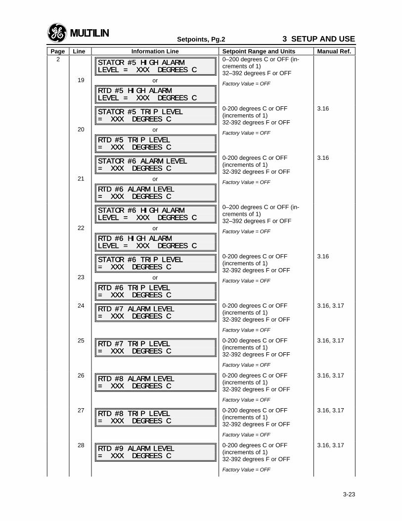
Setpoints, Pg.2 3 SETUP AND USE
Page Line Information Line Setpoint Range and Units Manual Ref.
3-23
2
19
STATOR #5 HIGH ALARMSTATOR #5 HIGH ALARMLEVEL = XXX DEGREES CLEVEL = XXX DEGREES C
or
RTD #5 HIGH ALARMRTD #5 HIGH ALARMLEVEL = XXX DEGREES CLEVEL = XXX DEGREES C
0–200 degrees C or OFF (in-crements of 1)32–392 degrees F or OFF
Factory Value = OFF
20
STATOR #5 TRIP LEVELSTATOR #5 TRIP LEVEL= XXX DEGREES C= XXX DEGREES C
or
RTD #5 TRIP LEVELRTD #5 TRIP LEVEL= XXX DEGREES C= XXX DEGREES C
0-200 degrees C or OFF(increments of 1)32-392 degrees F or OFF
Factory Value = OFF
3.16
21
STATOR #6 ALARM LEVELSTATOR #6 ALARM LEVEL= XXX DEGREES C= XXX DEGREES C
or
RTD #6 ALARM LEVELRTD #6 ALARM LEVEL= XXX DEGREES C= XXX DEGREES C
0-200 degrees C or OFF(increments of 1)32-392 degrees F or OFF
Factory Value = OFF
3.16
22
STATOR #6 HIGH ALARMSTATOR #6 HIGH ALARMLEVEL = XXX DEGREES CLEVEL = XXX DEGREES C
or
RTD #6 HIGH ALARMRTD #6 HIGH ALARMLEVEL = XXX DEGREES CLEVEL = XXX DEGREES C
0–200 degrees C or OFF (in-crements of 1)32–392 degrees F or OFF
Factory Value = OFF
23
STATOR #6 TRIP LEVELSTATOR #6 TRIP LEVEL= XXX DEGREES C= XXX DEGREES C
or
RTD #6 TRIP LEVELRTD #6 TRIP LEVEL= XXX DEGREES C= XXX DEGREES C
0-200 degrees C or OFF(increments of 1)32-392 degrees F or OFF
Factory Value = OFF
3.16
24 RTD #7 ALARM LEVELRTD #7 ALARM LEVEL= XXX DEGREES C= XXX DEGREES C
0-200 degrees C or OFF(increments of 1)32-392 degrees F or OFF
Factory Value = OFF
3.16, 3.17
25 RTD #7 TRIP LEVELRTD #7 TRIP LEVEL= XXX DEGREES C= XXX DEGREES C
0-200 degrees C or OFF(increments of 1)32-392 degrees F or OFF
Factory Value = OFF
3.16, 3.17
26 RTD #8 ALARM LEVELRTD #8 ALARM LEVEL= XXX DEGREES C= XXX DEGREES C
0-200 degrees C or OFF(increments of 1)32-392 degrees F or OFF
Factory Value = OFF
3.16, 3.17
27 RTD #8 TRIP LEVELRTD #8 TRIP LEVEL= XXX DEGREES C= XXX DEGREES C
0-200 degrees C or OFF(increments of 1)32-392 degrees F or OFF
Factory Value = OFF
3.16, 3.17
28 RTD #9 ALARM LEVELRTD #9 ALARM LEVEL= XXX DEGREES C= XXX DEGREES C
0-200 degrees C or OFF(increments of 1)32-392 degrees F or OFF
Factory Value = OFF
3.16, 3.17
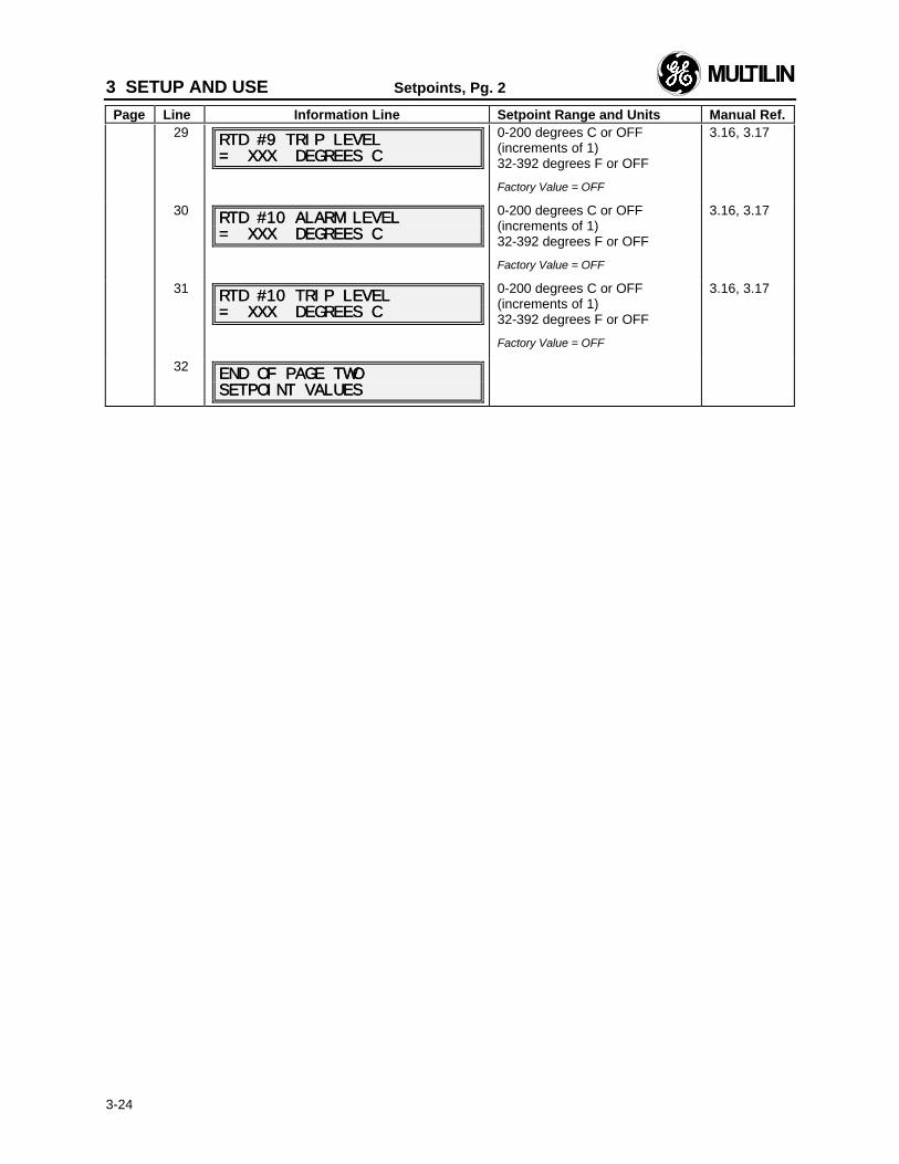
3 SETUP AND USE Setpoints, Pg. 2
Page Line Information Line Setpoint Range and Units Manual Ref.
3-24
29RTD #9 TRIP LEVELRTD #9 TRIP LEVEL= XXX DEGREES C= XXX DEGREES C
0-200 degrees C or OFF(increments of 1)32-392 degrees F or OFF
Factory Value = OFF
3.16, 3.17
30 RTD #10 ALARM LEVELRTD #10 ALARM LEVEL= XXX DEGREES C= XXX DEGREES C
0-200 degrees C or OFF(increments of 1)32-392 degrees F or OFF
Factory Value = OFF
3.16, 3.17
31RTD #10 TRIP LEVELRTD #10 TRIP LEVEL= XXX DEGREES C= XXX DEGREES C
0-200 degrees C or OFF(increments of 1)32-392 degrees F or OFF
Factory Value = OFF
3.16, 3.17
32END OF PAGE TWOEND OF PAGE TWOSETPOINT VALUESSETPOINT VALUES
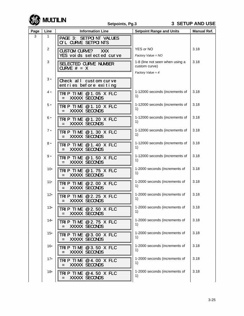
Setpoints, Pg.3 3 SETUP AND USE
Page Line Information Line Setpoint Range and Units Manual Ref.
3-25
3 1 PAGE 3: SETPOINT VALUESPAGE 3: SETPOINT VALUESO/L CURVE SETPOINTSO/L CURVE SETPOINTS
2CUSTOM CURVE? XXXCUSTOM CURVE? XXXYES voids selected curveYES voids selected curve
YES or NO
Factory Value = NO
3.18
3 SELECTED CURVE NUMBERSELECTED CURVE NUMBERCURVE # = XCURVE # = X
1-8 (line not seen when using acustom curve)
Factory Value = 4
3.18
3 • Check all custom curveCheck all custom curveentries before exitingentries before exiting
4 • TRIP TIME @ 1.05 X FLCTRIP TIME @ 1.05 X FLC = XXXXX SECONDS = XXXXX SECONDS
1-12000 seconds (increments of1)
3.18
5 • TRIP TIME @ 1.10 X FLCTRIP TIME @ 1.10 X FLC = XXXXX SECONDS = XXXXX SECONDS
1-12000 seconds (increments of1)
3.18
6 • TRIP TIME @ 1.20 X FLCTRIP TIME @ 1.20 X FLC = XXXXX SECONDS = XXXXX SECONDS
1-12000 seconds (increments of1)
3.18
7 • TRIP TIME @ 1.30 X FLCTRIP TIME @ 1.30 X FLC = XXXXX SECONDS = XXXXX SECONDS
1-12000 seconds (increments of1)
3.18
8 • TRIP TIME @ 1.40 X FLCTRIP TIME @ 1.40 X FLC = XXXXX SECONDS = XXXXX SECONDS
1-12000 seconds (increments of1)
3.18
9 • TRIP TIME @ 1.50 X FLCTRIP TIME @ 1.50 X FLC = XXXXX SECONDS = XXXXX SECONDS
1-12000 seconds (increments of1)
3.18
10• TRIP TIME @ 1.75 X FLCTRIP TIME @ 1.75 X FLC = XXXXX SECONDS = XXXXX SECONDS
1-2000 seconds (increments of1)
3.18
11• TRIP TIME @ 2.00 X FLCTRIP TIME @ 2.00 X FLC = XXXXX SECONDS = XXXXX SECONDS
1-2000 seconds (increments of1)
3.18
12• TRIP TIME @ 2.25 X FLCTRIP TIME @ 2.25 X FLC = XXXXX SECONDS = XXXXX SECONDS
1-2000 seconds (increments of1)
3.18
13• TRIP TIME @ 2.50 X FLCTRIP TIME @ 2.50 X FLC = XXXXX SECONDS = XXXXX SECONDS
1-2000 seconds (increments of1)
3.18
14• TRIP TIME @ 2.75 X FLCTRIP TIME @ 2.75 X FLC = XXXXX SECONDS = XXXXX SECONDS
1-2000 seconds (increments of1)
3.18
15• TRIP TIME @ 3.00 X FLCTRIP TIME @ 3.00 X FLC = XXXXX SECONDS = XXXXX SECONDS
1-2000 seconds (increments of1)
3.18
16• TRIP TIME @ 3.50 X FLCTRIP TIME @ 3.50 X FLC = XXXXX SECONDS = XXXXX SECONDS
1-2000 seconds (increments of1)
3.18
17• TRIP TIME @ 4.00 X FLCTRIP TIME @ 4.00 X FLC = XXXXX SECONDS = XXXXX SECONDS
1-2000 seconds (increments of1)
3.18
18• TRIP TIME @ 4.50 X FLCTRIP TIME @ 4.50 X FLC = XXXXX SECONDS = XXXXX SECONDS
1-2000 seconds (increments of1)
3.18
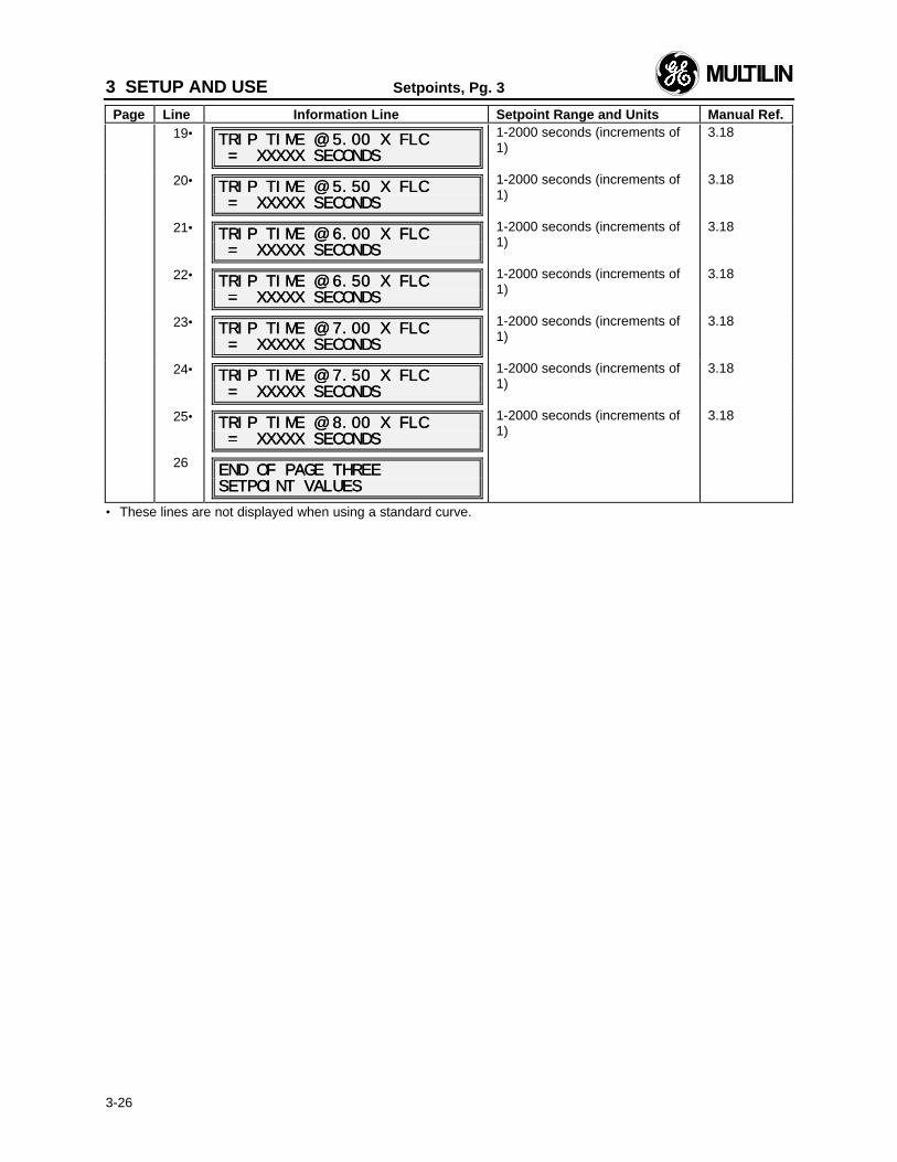
3 SETUP AND USE Setpoints, Pg. 3
Page Line Information Line Setpoint Range and Units Manual Ref.
3-26
19• TRIP TIME @ 5.00 X FLCTRIP TIME @ 5.00 X FLC = XXXXX SECONDS = XXXXX SECONDS
1-2000 seconds (increments of1)
3.18
20• TRIP TIME @ 5.50 X FLCTRIP TIME @ 5.50 X FLC = XXXXX SECONDS = XXXXX SECONDS
1-2000 seconds (increments of1)
3.18
21• TRIP TIME @ 6.00 X FLCTRIP TIME @ 6.00 X FLC = XXXXX SECONDS = XXXXX SECONDS
1-2000 seconds (increments of1)
3.18
22• TRIP TIME @ 6.50 X FLCTRIP TIME @ 6.50 X FLC = XXXXX SECONDS = XXXXX SECONDS
1-2000 seconds (increments of1)
3.18
23• TRIP TIME @ 7.00 X FLCTRIP TIME @ 7.00 X FLC = XXXXX SECONDS = XXXXX SECONDS
1-2000 seconds (increments of1)
3.18
24• TRIP TIME @ 7.50 X FLCTRIP TIME @ 7.50 X FLC = XXXXX SECONDS = XXXXX SECONDS
1-2000 seconds (increments of1)
3.18
25• TRIP TIME @ 8.00 X FLCTRIP TIME @ 8.00 X FLC = XXXXX SECONDS = XXXXX SECONDS
1-2000 seconds (increments of1)
3.18
26 END OF PAGE THREEEND OF PAGE THREESETPOINT VALUESSETPOINT VALUES
• These lines are not displayed when using a standard curve.
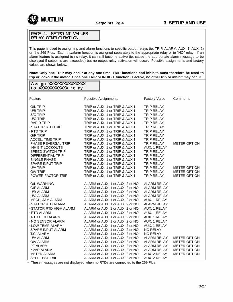
Setpoints, Pg.4 3 SETUP AND USE
3-27
PAGE 4: SETPOINT VALUESPAGE 4: SETPOINT VALUESRELAY CONFIGURATIONRELAY CONFIGURATION
This page is used to assign trip and alarm functions to specific output relays (ie. TRIP, ALARM, AUX. 1, AUX. 2)on the 269 Plus. Each trip/alarm function is assigned separately to the appropriate relay or to "NO" relay. If analarm feature is assigned to no relay, it can still become active (ie. cause the appropriate alarm message to bedisplayed if setpoints are exceeded) but no output relay activation will occur. Possible assignments and factoryvalues are shown below.
Note: Only one TRIP may occur at any one time. TRIP functions and inhibits must therefore be used totrip or lockout the motor. Once one TRIP or INHIBIT function is active, no other trip or inhibit may occur.
Assign XXXXXXXXXXXXXXXAssign XXXXXXXXXXXXXXXto XXXXXXXXXXXX relayto XXXXXXXXXXXX relay
Feature Possible Assignments Factory Value Comments
O/L TRIP TRIP or AUX. 1 or TRIP & AUX.1 TRIP RELAY U/B TRIP TRIP or AUX. 1 or TRIP & AUX.1 TRIP RELAY S/C TRIP TRIP or AUX. 1 or TRIP & AUX.1 TRIP RELAY U/C TRIP TRIP or AUX. 1 or TRIP & AUX.1 TRIP RELAY RAPID TRIP TRIP or AUX. 1 or TRIP & AUX.1 TRIP RELAY•STATOR RTD TRIP TRIP or AUX. 1 or TRIP & AUX.1 TRIP RELAY•RTD TRIP TRIP or AUX. 1 or TRIP & AUX.1 TRIP RELAY G/F TRIP TRIP or AUX. 1 or TRIP & AUX.1 TRIP RELAY ACCEL. TIME TRIP TRIP or AUX. 1 or TRIP & AUX.1 TRIP RELAY PHASE REVERSAL TRIP TRIP or AUX. 1 or TRIP & AUX.1 TRIP RELAY METER OPTION INHIBIT LOCKOUTS TRIP or AUX. 1 or TRIP & AUX.1 AUX. 1 RELAY SPEED SWITCH TRIP TRIP or AUX. 1 or TRIP & AUX.1 TRIP RELAY DIFFERENTIAL TRIP TRIP or AUX. 1 or TRIP & AUX.1 TRIP RELAY SINGLE PHASE TRIP or AUX. 1 or TRIP & AUX.1 TRIP RELAY SPARE INPUT TRIP TRIP or AUX. 1 or TRIP & AUX.1 TRIP RELAY U/V TRIP TRIP or AUX. 1 or TRIP & AUX.1 TRIP RELAY METER OPTION O/V TRIP TRIP or AUX. 1 or TRIP & AUX.1 TRIP RELAY METER OPTION POWER FACTOR TRIP TRIP or AUX. 1 or TRIP & AUX.1 TRIP RELAY METER OPTION
O/L WARNING ALARM or AUX. 1 or AUX. 2 or NO ALARM RELAY G/F ALARM ALARM or AUX. 1 or AUX. 2 or NO ALARM RELAY U/B ALARM ALARM or AUX. 1 or AUX. 2 or NO ALARM RELAY U/C ALARM ALARM or AUX. 1 or AUX. 2 or NO ALARM RELAY MECH. JAM ALARM ALARM or AUX. 1 or AUX. 2 or NO AUX. 1 RELAY•STATOR RTD ALARM ALARM or AUX. 1 or AUX. 2 or NO ALARM RELAY•STATOR RTD HIGH ALARM ALARM or AUX. 1 or AUX. 2 or NO AUX. 1 RELAY•RTD ALARM ALARM or AUX. 1 or AUX. 2 or NO AUX. 1 RELAY•RTD HIGH ALARM ALARM or AUX. 1 or AUX. 2 or NO AUX. 1 RELAY•NO SENSOR ALARM ALARM or AUX. 1 or AUX. 2 or NO AUX. 1 RELAY•LOW TEMP ALARM ALARM or AUX. 1 or AUX. 2 or NO AUX. 1 RELAY SPARE INPUT ALARM ALARM or AUX. 1 or AUX. 2 or NO NO RELAY T.C. ALARM ALARM or AUX. 1 or AUX. 2 or NO NO RELAY U/V ALARM ALARM or AUX. 1 or AUX. 2 or NO ALARM RELAY METER OPTION O/V ALARM ALARM or AUX. 1 or AUX. 2 or NO ALARM RELAY METER OPTION PF ALARM ALARM or AUX. 1 or AUX. 2 or NO ALARM RELAY METER OPTION KVAR ALARM ALARM or AUX. 1 or AUX. 2 or NO ALARM RELAY METER OPTION METER ALARM ALARM or AUX. 1 or AUX. 2 or NO AUX. 2 RELAY METER OPTION SELF TEST FAIL ALARM or AUX. 1 or AUX. 2 or NO AUX. 2 RELAY
• These messages are not displayed when no RTDs are connected to the 269 Plus.
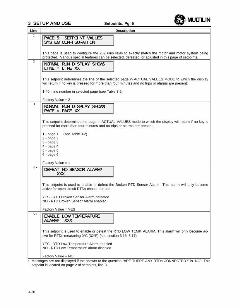
3 SETUP AND USE Setpoints, Pg. 5
Line Description
3-28
1PAGE 5: SETPOINT VALUESPAGE 5: SETPOINT VALUESSYSTEM CONFIGURATIONSYSTEM CONFIGURATION
This page is used to configure the 269 Plus relay to exactly match the motor and motor system beingprotected. Various special features can be selected, defeated, or adjusted in this page of setpoints.
2NORMAL RUN DISPLAY SHOWSNORMAL RUN DISPLAY SHOWSLINE = LINE XXLINE = LINE XX
This setpoint determines the line of the selected page in ACTUAL VALUES MODE to which the displaywill return if no key is pressed for more than four minutes and no trips or alarms are present:
1-40 - line number in selected page (see Table 3-2)
Factory Value = 23
NORMAL RUN DISPLAY SHOWSNORMAL RUN DISPLAY SHOWSPAGE = PAGE XXPAGE = PAGE XX
This setpoint determines the page in ACTUAL VALUES mode to which the display will return if no key ispressed for more than four minutes and no trips or alarms are present:
1 - page 1 (see Table 3-2)2 - page 23 - page 34 - page 45 - page 56 - page 6
Factory Value = 14 •
DEFEAT NO SENSOR ALARM?DEFEAT NO SENSOR ALARM? XXX XXX
This setpoint is used to enable or defeat the Broken RTD Sensor Alarm. This alarm will only becomeactive for open circuit RTDs chosen for use:
YES - RTD Broken Sensor Alarm defeated.NO - RTD Broken Sensor Alarm enabled.
Factory Value = YES5 •
ENABLE LOW TEMPERATUREENABLE LOW TEMPERATUREALARM? XXXALARM? XXX
This setpoint is used to enable or defeat the RTD LOW TEMP. ALARM. This alarm will only become ac-tive for RTDs measuring 0°C (32°F) (see section 3.16–3.17).
YES - RTD Low Temperature Alarm enabledNO - RTD Low Temperature Alarm disabled.
Factory Value = NO• Messages are not displayed if the answer to the question “ARE THERE ANY RTDs CONNECTED?” is “NO”. This
setpoint is located on page 2 of setpoints, line 3.
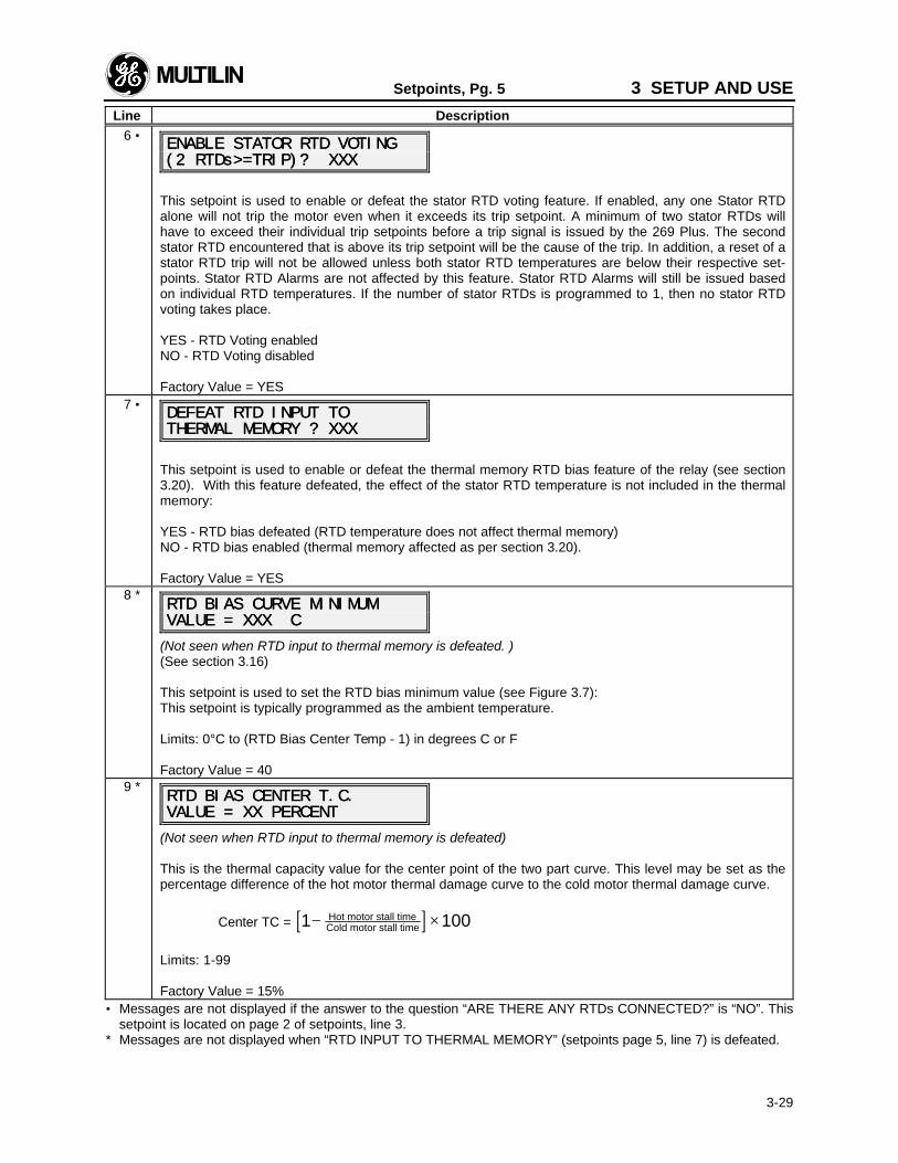
Setpoints, Pg. 5 3 SETUP AND USE
Line Description
3-29
6 •ENABLE STATOR RTD VOTINGENABLE STATOR RTD VOTING(2 RTDs>=TRIP)? XXX(2 RTDs>=TRIP)? XXX
This setpoint is used to enable or defeat the stator RTD voting feature. If enabled, any one Stator RTDalone will not trip the motor even when it exceeds its trip setpoint. A minimum of two stator RTDs willhave to exceed their individual trip setpoints before a trip signal is issued by the 269 Plus. The secondstator RTD encountered that is above its trip setpoint will be the cause of the trip. In addition, a reset of astator RTD trip will not be allowed unless both stator RTD temperatures are below their respective set-points. Stator RTD Alarms are not affected by this feature. Stator RTD Alarms will still be issued basedon individual RTD temperatures. If the number of stator RTDs is programmed to 1, then no stator RTDvoting takes place.
YES - RTD Voting enabledNO - RTD Voting disabled
Factory Value = YES7 •
DEFEAT RTD INPUT TODEFEAT RTD INPUT TOTHERMAL THERMAL MEMORY ? XXXMEMORY ? XXX
This setpoint is used to enable or defeat the thermal memory RTD bias feature of the relay (see section3.20). With this feature defeated, the effect of the stator RTD temperature is not included in the thermalmemory:
YES - RTD bias defeated (RTD temperature does not affect thermal memory)NO - RTD bias enabled (thermal memory affected as per section 3.20).
Factory Value = YES8 *
RTD BIAS CURVE MINIMUMRTD BIAS CURVE MINIMUMVALUE = XXX CVALUE = XXX C
(Not seen when RTD input to thermal memory is defeated. )(See section 3.16)
This setpoint is used to set the RTD bias minimum value (see Figure 3.7):This setpoint is typically programmed as the ambient temperature.
Limits: 0°C to (RTD Bias Center Temp - 1) in degrees C or F
Factory Value = 409 *
RTD BIAS CENTER T.C.RTD BIAS CENTER T.C.VALUE = XX PERCENTVALUE = XX PERCENT
(Not seen when RTD input to thermal memory is defeated)
This is the thermal capacity value for the center point of the two part curve. This level may be set as thepercentage difference of the hot motor thermal damage curve to the cold motor thermal damage curve.
Center TC = [ ]1 100− ×Hot motor stall timeCold motor stall time
Limits: 1-99
Factory Value = 15%• Messages are not displayed if the answer to the question “ARE THERE ANY RTDs CONNECTED?” is “NO”. This
setpoint is located on page 2 of setpoints, line 3.* Messages are not displayed when “RTD INPUT TO THERMAL MEMORY” (setpoints page 5, line 7) is defeated.
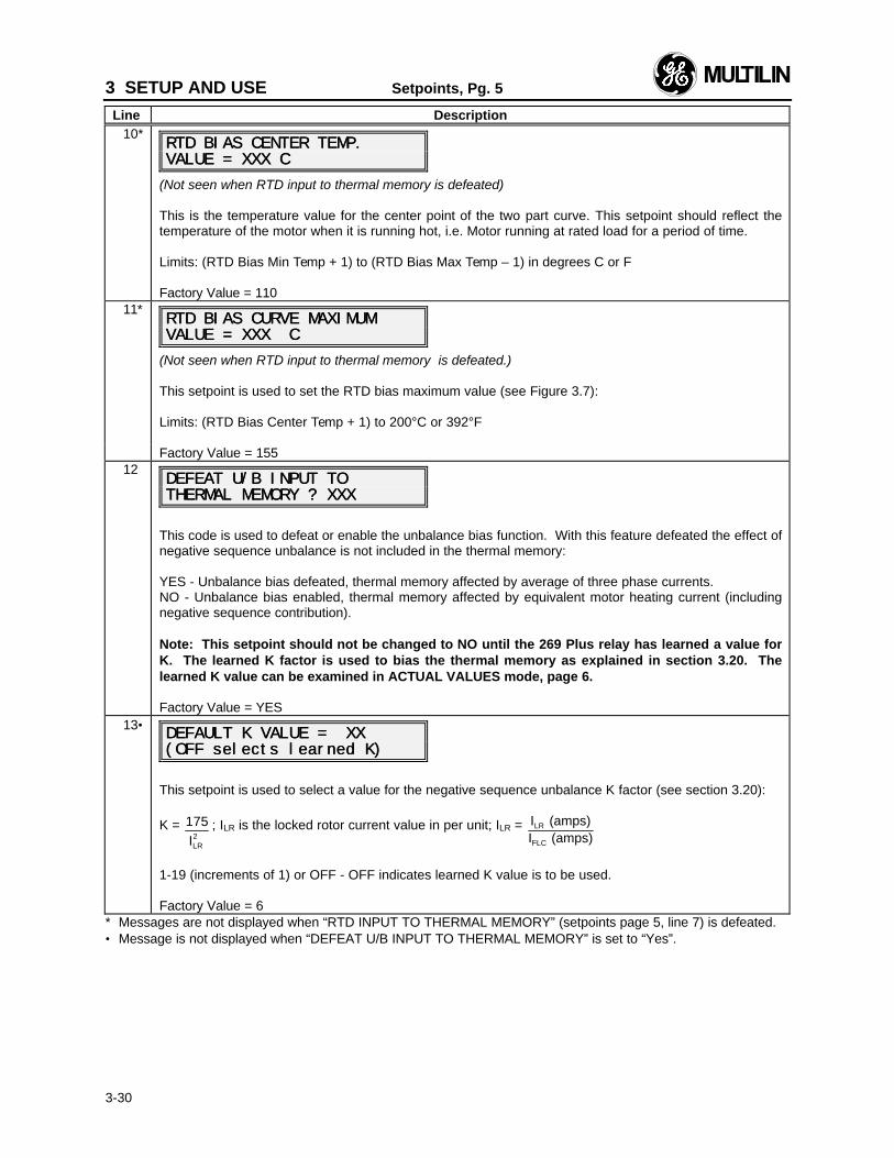
3 SETUP AND USE Setpoints, Pg. 5
Line Description
3-30
10*RTD BIAS CENTER TEMP.RTD BIAS CENTER TEMP.VALUE = XXX CVALUE = XXX C
(Not seen when RTD input to thermal memory is defeated)
This is the temperature value for the center point of the two part curve. This setpoint should reflect thetemperature of the motor when it is running hot, i.e. Motor running at rated load for a period of time.
Limits: (RTD Bias Min Temp + 1) to (RTD Bias Max Temp – 1) in degrees C or F
Factory Value = 11011*
RTD BIAS CURVE MAXIMUMRTD BIAS CURVE MAXIMUMVALUE = XXX CVALUE = XXX C
(Not seen when RTD input to thermal memory is defeated.)
This setpoint is used to set the RTD bias maximum value (see Figure 3.7):
Limits: (RTD Bias Center Temp + 1) to 200°C or 392°F
Factory Value = 15512
DEFEAT U/B INPUT TODEFEAT U/B INPUT TOTHERMAL THERMAL MEMORY ? XXXMEMORY ? XXX
This code is used to defeat or enable the unbalance bias function. With this feature defeated the effect ofnegative sequence unbalance is not included in the thermal memory:
YES - Unbalance bias defeated, thermal memory affected by average of three phase currents.NO - Unbalance bias enabled, thermal memory affected by equivalent motor heating current (includingnegative sequence contribution).
Note: This setpoint should not be changed to NO until the 269 Plus relay has learned a value forK. The learned K factor is used to bias the thermal memory as explained in section 3.20. Thelearned K value can be examined in ACTUAL VALUES mode, page 6.
Factory Value = YES13•
DEFAULT K VALUE = XXDEFAULT K VALUE = XX(OFF selects learned K)(OFF selects learned K)
This setpoint is used to select a value for the negative sequence unbalance K factor (see section 3.20):
K = 175
ILR2
; ILR is the locked rotor current value in per unit; ILR = I (amps)I (amps)
LR
FLC
1-19 (increments of 1) or OFF - OFF indicates learned K value is to be used.
Factory Value = 6* Messages are not displayed when “RTD INPUT TO THERMAL MEMORY” (setpoints page 5, line 7) is defeated.• Message is not displayed when “DEFEAT U/B INPUT TO THERMAL MEMORY” is set to “Yes”.
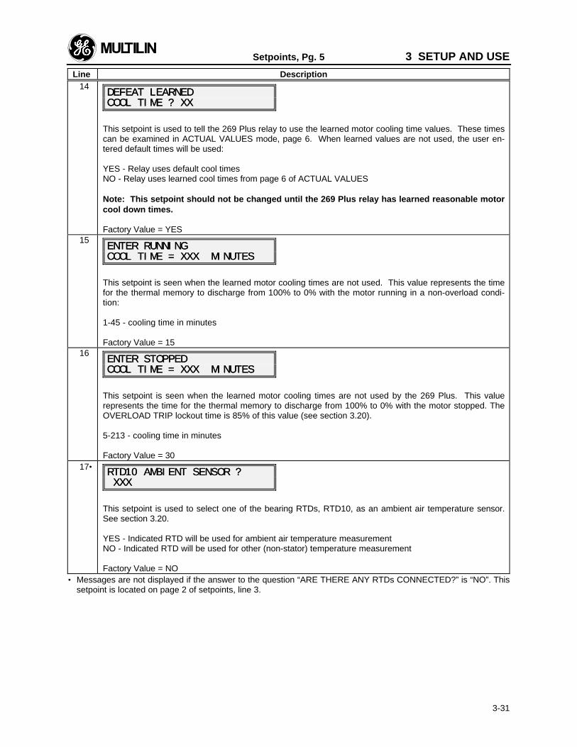
Setpoints, Pg. 5 3 SETUP AND USE
Line Description
3-31
14DEFEAT LEARNEDDEFEAT LEARNEDCOOL COOL TIME ? XXTIME ? XX
This setpoint is used to tell the 269 Plus relay to use the learned motor cooling time values. These timescan be examined in ACTUAL VALUES mode, page 6. When learned values are not used, the user en-tered default times will be used:
YES - Relay uses default cool timesNO - Relay uses learned cool times from page 6 of ACTUAL VALUES
Note: This setpoint should not be changed until the 269 Plus relay has learned reasonable motorcool down times.
Factory Value = YES15
ENTER RUNNINGENTER RUNNINGCOOL TIME = XXX MINUTESCOOL TIME = XXX MINUTES
This setpoint is seen when the learned motor cooling times are not used. This value represents the timefor the thermal memory to discharge from 100% to 0% with the motor running in a non-overload condi-tion:
1-45 - cooling time in minutes
Factory Value = 1516
ENTER STOPPEDENTER STOPPEDCOOL TIME = XXX MINUTESCOOL TIME = XXX MINUTES
This setpoint is seen when the learned motor cooling times are not used by the 269 Plus. This valuerepresents the time for the thermal memory to discharge from 100% to 0% with the motor stopped. TheOVERLOAD TRIP lockout time is 85% of this value (see section 3.20).
5-213 - cooling time in minutes
Factory Value = 3017•
RTD10 AMBIENT RTD10 AMBIENT SENSOR ?SENSOR ? XXX XXX
This setpoint is used to select one of the bearing RTDs, RTD10, as an ambient air temperature sensor.See section 3.20.
YES - Indicated RTD will be used for ambient air temperature measurementNO - Indicated RTD will be used for other (non-stator) temperature measurement
Factory Value = NO• Messages are not displayed if the answer to the question “ARE THERE ANY RTDs CONNECTED?” is “NO”. This
setpoint is located on page 2 of setpoints, line 3.
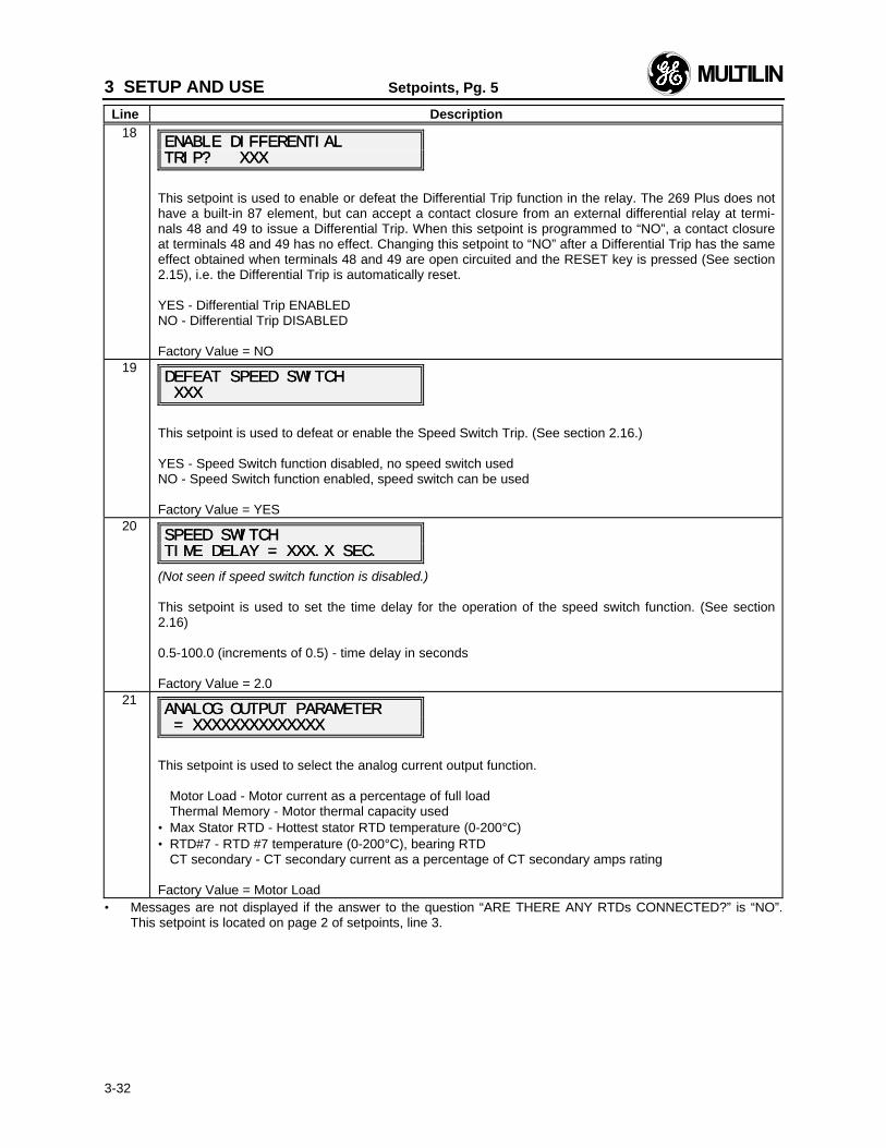
3 SETUP AND USE Setpoints, Pg. 5
Line Description
3-32
18ENABLE DIFFERENTIALENABLE DIFFERENTIALTRIP? XXXTRIP? XXX
This setpoint is used to enable or defeat the Differential Trip function in the relay. The 269 Plus does nothave a built-in 87 element, but can accept a contact closure from an external differential relay at termi-nals 48 and 49 to issue a Differential Trip. When this setpoint is programmed to “NO”, a contact closureat terminals 48 and 49 has no effect. Changing this setpoint to “NO” after a Differential Trip has the sameeffect obtained when terminals 48 and 49 are open circuited and the RESET key is pressed (See section2.15), i.e. the Differential Trip is automatically reset.
YES - Differential Trip ENABLEDNO - Differential Trip DISABLED
Factory Value = NO19
DEFEAT SPEED SWITCHDEFEAT SPEED SWITCH XXX XXX
This setpoint is used to defeat or enable the Speed Switch Trip. (See section 2.16.)
YES - Speed Switch function disabled, no speed switch usedNO - Speed Switch function enabled, speed switch can be used
Factory Value = YES20
SPEED SWITCHSPEED SWITCHTIME DELAY = XXX.X SEC.TIME DELAY = XXX.X SEC.
(Not seen if speed switch function is disabled.)
This setpoint is used to set the time delay for the operation of the speed switch function. (See section2.16)
0.5-100.0 (increments of 0.5) - time delay in seconds
Factory Value = 2.021
ANALOG OUTPUT PARAMETERANALOG OUTPUT PARAMETER = XXXXXXXXXXXXXX = XXXXXXXXXXXXXX
This setpoint is used to select the analog current output function.
Motor Load - Motor current as a percentage of full loadThermal Memory - Motor thermal capacity used
• Max Stator RTD - Hottest stator RTD temperature (0-200°C)• RTD#7 - RTD #7 temperature (0-200°C), bearing RTD
CT secondary - CT secondary current as a percentage of CT secondary amps rating
Factory Value = Motor Load• Messages are not displayed if the answer to the question “ARE THERE ANY RTDs CONNECTED?” is “NO”.
This setpoint is located on page 2 of setpoints, line 3.
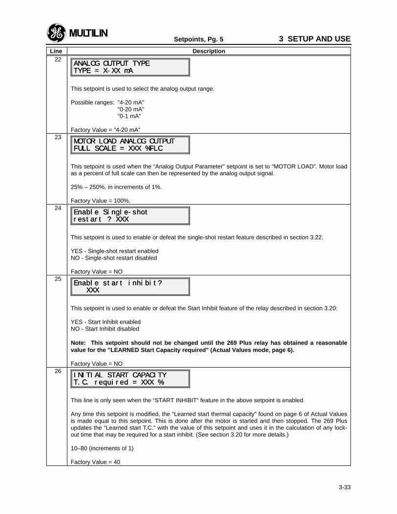
Setpoints, Pg. 5 3 SETUP AND USE
Line Description
3-33
22ANALOG OUTPUT TYPEANALOG OUTPUT TYPETYPE = X-XX mATYPE = X-XX mA
This setpoint is used to select the analog output range.
Possible ranges: "4-20 mA""0-20 mA""0-1 mA"
Factory Value = "4-20 mA"23
MOTOR LOAD ANALOG OUTPUTMOTOR LOAD ANALOG OUTPUTFULL SCALE = XXX %FLCFULL SCALE = XXX %FLC
This setpoint is used when the “Analog Output Parameter” setpoint is set to “MOTOR LOAD”. Motor loadas a percent of full scale can then be represented by the analog output signal.
25% – 250%, in increments of 1%.
Factory Value = 100%.24
Enable Single-shotEnable Single-shotrestart ? XXXrestart ? XXX
This setpoint is used to enable or defeat the single-shot restart feature described in section 3.22.
YES - Single-shot restart enabledNO - Single-shot restart disabled
Factory Value = NO25
Enable Enable start inhibit?start inhibit? XXX XXX
This setpoint is used to enable or defeat the Start Inhibit feature of the relay described in section 3.20:
YES - Start Inhibit enabledNO - Start Inhibit disabled
Note: This setpoint should not be changed until the 269 Plus relay has obtained a reasonablevalue for the "LEARNED Start Capacity required" (Actual Values mode, page 6).
Factory Value = NO26
INITIAL START CAPACITYINITIAL START CAPACITYT.C. required = XXX %T.C. required = XXX %
This line is only seen when the “START INHIBIT” feature in the above setpoint is enabled.
Any time this setpoint is modified, the “Learned start thermal capacity” found on page 6 of Actual Valuesis made equal to this setpoint. This is done after the motor is started and then stopped. The 269 Plusupdates the “Learned start T.C.” with the value of this setpoint and uses it in the calculation of any lock-out time that may be required for a start inhibit. (See section 3.20 for more details.)
10–80 (increments of 1)
Factory Value = 40
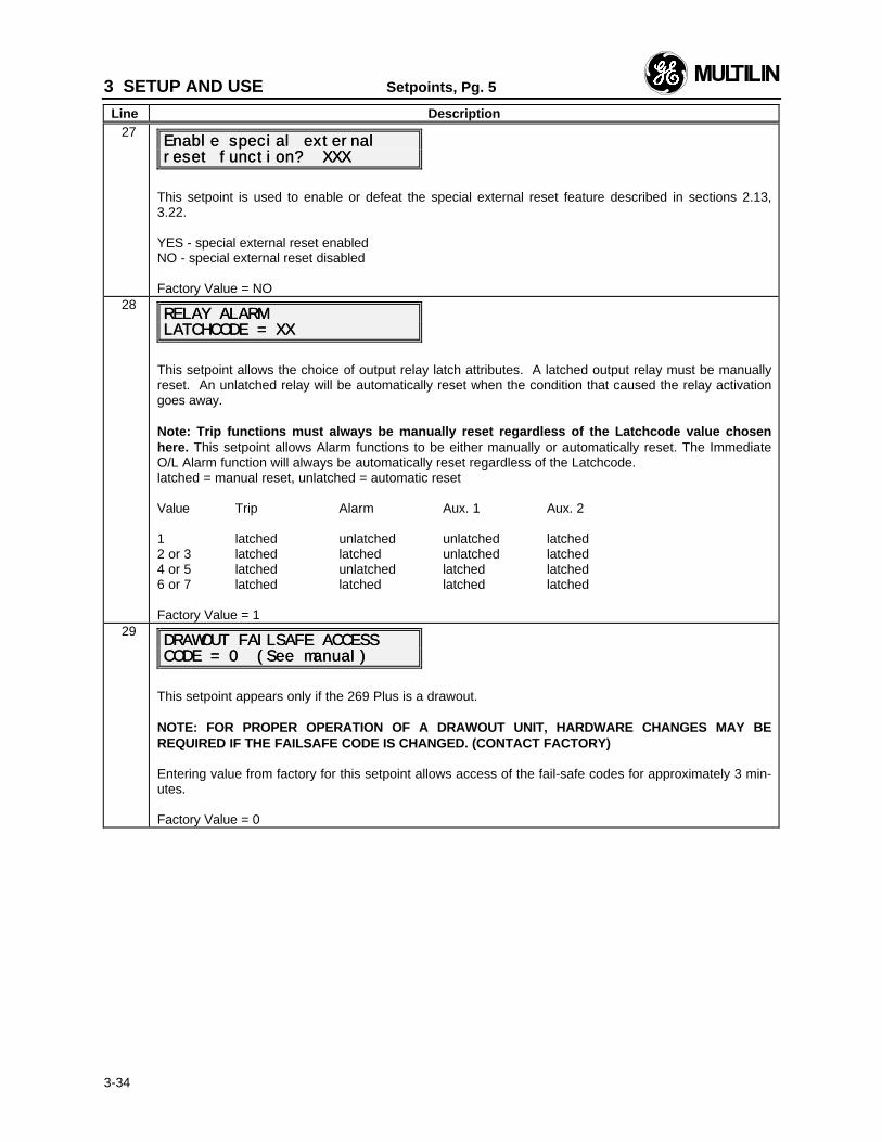
3 SETUP AND USE Setpoints, Pg. 5
Line Description
3-34
27Enable special externalEnable special externalreset function? XXXreset function? XXX
This setpoint is used to enable or defeat the special external reset feature described in sections 2.13,3.22.
YES - special external reset enabledNO - special external reset disabled
Factory Value = NO28
RELAY ALARMRELAY ALARMLATCHCODE = XXLATCHCODE = XX
This setpoint allows the choice of output relay latch attributes. A latched output relay must be manuallyreset. An unlatched relay will be automatically reset when the condition that caused the relay activationgoes away.
Note: Trip functions must always be manually reset regardless of the Latchcode value chosenhere. This setpoint allows Alarm functions to be either manually or automatically reset. The ImmediateO/L Alarm function will always be automatically reset regardless of the Latchcode.latched = manual reset, unlatched = automatic reset
Value Trip Alarm Aux. 1 Aux. 2
1 latched unlatched unlatched latched2 or 3 latched latched unlatched latched4 or 5 latched unlatched latched latched6 or 7 latched latched latched latched
Factory Value = 129
DRAWOUT FAILSAFE ACCESSDRAWOUT FAILSAFE ACCESSCODE = 0 (See manual)CODE = 0 (See manual)
This setpoint appears only if the 269 Plus is a drawout.
NOTE: FOR PROPER OPERATION OF A DRAWOUT UNIT, HARDWARE CHANGES MAY BEREQUIRED IF THE FAILSAFE CODE IS CHANGED. (CONTACT FACTORY)
Entering value from factory for this setpoint allows access of the fail-safe codes for approximately 3 min-utes.
Factory Value = 0
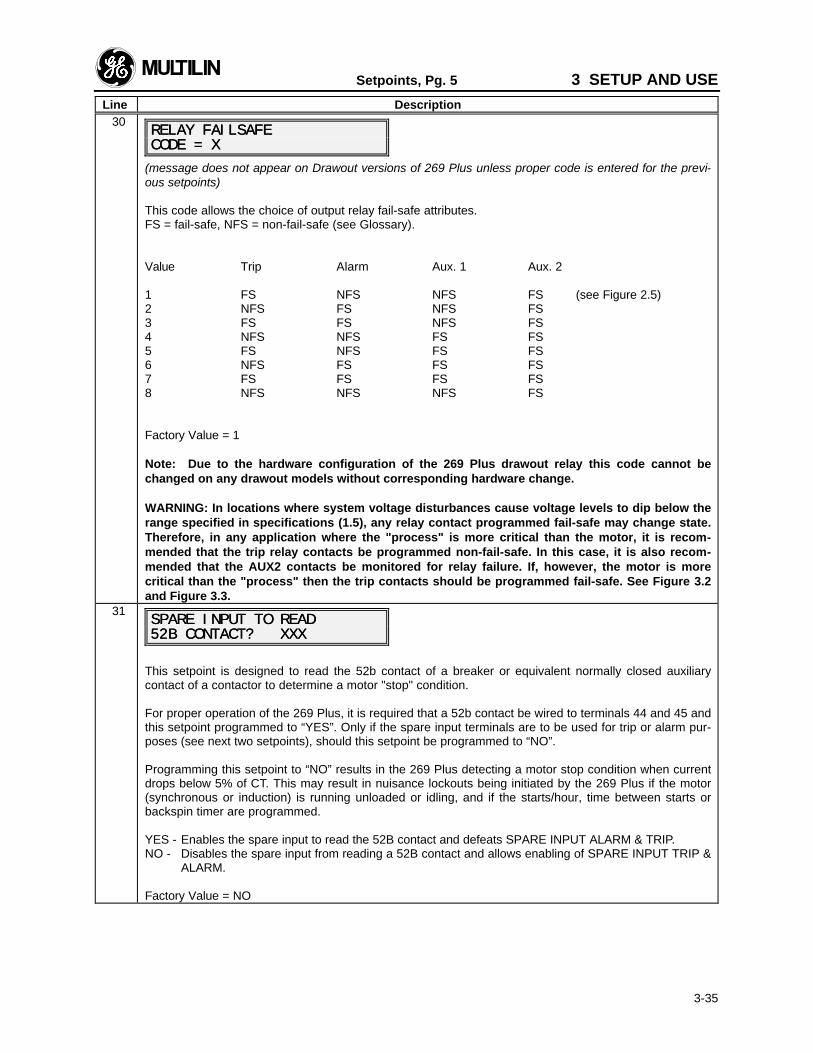
Setpoints, Pg. 5 3 SETUP AND USE
Line Description
3-35
30RELAY FAILSAFERELAY FAILSAFECODE = XCODE = X
(message does not appear on Drawout versions of 269 Plus unless proper code is entered for the previ-ous setpoints)
This code allows the choice of output relay fail-safe attributes.FS = fail-safe, NFS = non-fail-safe (see Glossary).
Value Trip Alarm Aux. 1 Aux. 2
1 FS NFS NFS FS (see Figure 2.5)2 NFS FS NFS FS3 FS FS NFS FS4 NFS NFS FS FS5 FS NFS FS FS6 NFS FS FS FS7 FS FS FS FS8 NFS NFS NFS FS
Factory Value = 1
Note: Due to the hardware configuration of the 269 Plus drawout relay this code cannot bechanged on any drawout models without corresponding hardware change.
WARNING: In locations where system voltage disturbances cause voltage levels to dip below therange specified in specifications (1.5), any relay contact programmed fail-safe may change state.Therefore, in any application where the "process" is more critical than the motor, it is recom-mended that the trip relay contacts be programmed non-fail-safe. In this case, it is also recom-mended that the AUX2 contacts be monitored for relay failure. If, however, the motor is morecritical than the "process" then the trip contacts should be programmed fail-safe. See Figure 3.2and Figure 3.3.
31SPARE INPUT TO READSPARE INPUT TO READ52B CONTACT? XXX52B CONTACT? XXX
This setpoint is designed to read the 52b contact of a breaker or equivalent normally closed auxiliarycontact of a contactor to determine a motor "stop" condition.
For proper operation of the 269 Plus, it is required that a 52b contact be wired to terminals 44 and 45 andthis setpoint programmed to “YES”. Only if the spare input terminals are to be used for trip or alarm pur-poses (see next two setpoints), should this setpoint be programmed to “NO”.
Programming this setpoint to “NO” results in the 269 Plus detecting a motor stop condition when currentdrops below 5% of CT. This may result in nuisance lockouts being initiated by the 269 Plus if the motor(synchronous or induction) is running unloaded or idling, and if the starts/hour, time between starts orbackspin timer are programmed.
YES - Enables the spare input to read the 52B contact and defeats SPARE INPUT ALARM & TRIP.NO - Disables the spare input from reading a 52B contact and allows enabling of SPARE INPUT TRIP &
ALARM.
Factory Value = NO
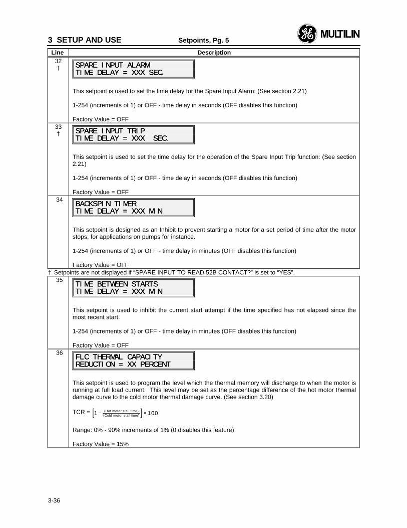
3 SETUP AND USE Setpoints, Pg. 5
Line Description
3-36
32† SPARE INPUT ALARMSPARE INPUT ALARM
TIME DELAY = XXX SEC.TIME DELAY = XXX SEC.
This setpoint is used to set the time delay for the Spare Input Alarm: (See section 2.21)
1-254 (increments of 1) or OFF - time delay in seconds (OFF disables this function)
Factory Value = OFF33† SPARE INPUT TRIPSPARE INPUT TRIP
TIME DELAY = TIME DELAY = XXX SEC.XXX SEC.
This setpoint is used to set the time delay for the operation of the Spare Input Trip function: (See section2.21)
1-254 (increments of 1) or OFF - time delay in seconds (OFF disables this function)
Factory Value = OFF34
BACKSPIN TIMERBACKSPIN TIMERTIME DELAY = XXX MINTIME DELAY = XXX MIN
This setpoint is designed as an Inhibit to prevent starting a motor for a set period of time after the motorstops, for applications on pumps for instance.
1-254 (increments of 1) or OFF - time delay in minutes (OFF disables this function)
Factory Value = OFF† Setpoints are not displayed if “SPARE INPUT TO READ 52B CONTACT?” is set to “YES”.
35TIME BETWEEN STARTSTIME BETWEEN STARTSTIME DELAY = XXX MINTIME DELAY = XXX MIN
This setpoint is used to inhibit the current start attempt if the time specified has not elapsed since themost recent start.
1-254 (increments of 1) or OFF - time delay in minutes (OFF disables this function)
Factory Value = OFF36
FLC THERMAL CAPACITYFLC THERMAL CAPACITYREDUCTION = XX PERCENTREDUCTION = XX PERCENT
This setpoint is used to program the level which the thermal memory will discharge to when the motor isrunning at full load current. This level may be set as the percentage difference of the hot motor thermaldamage curve to the cold motor thermal damage curve. (See section 3.20)
TCR = [ ]1 100− ×(Hot motor stall time)(Cold motor stall time)
Range: 0% - 90% increments of 1% (0 disables this feature)
Factory Value = 15%
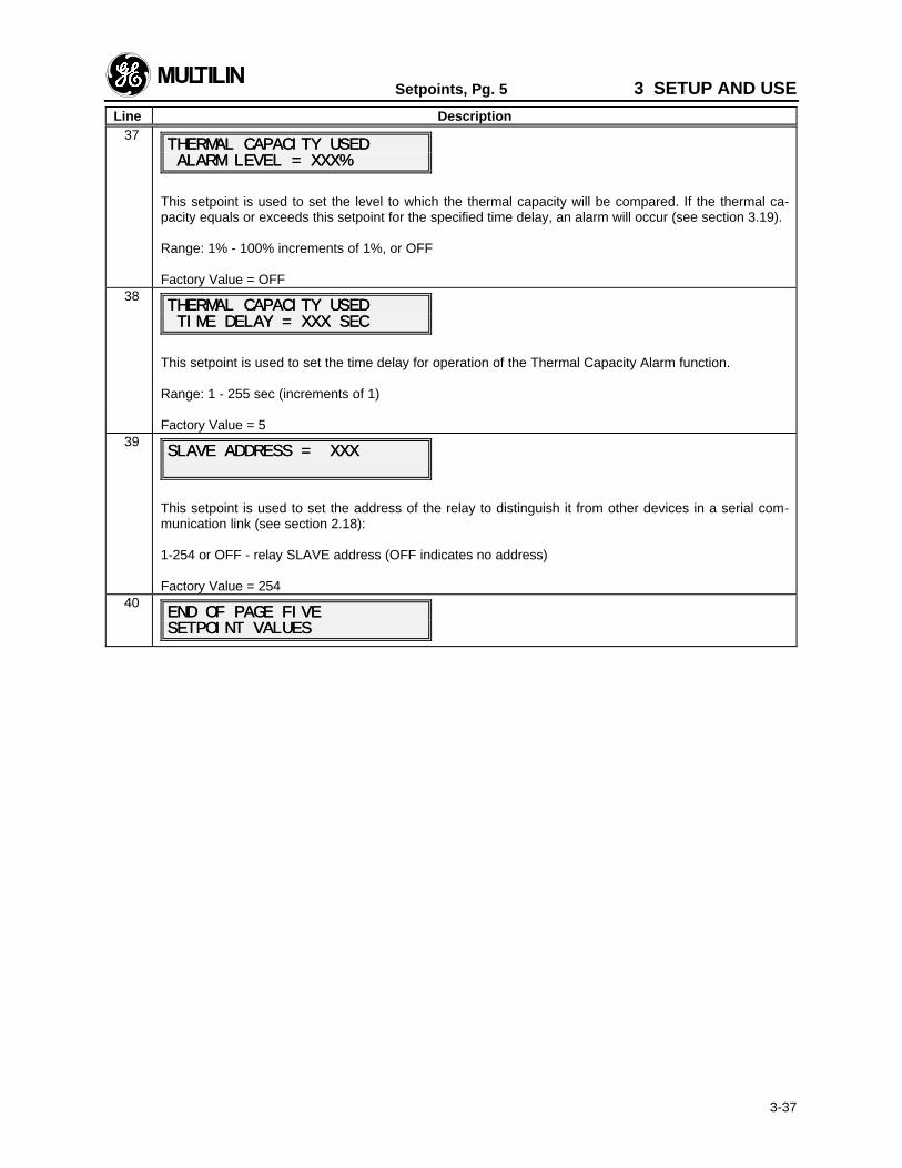
Setpoints, Pg. 5 3 SETUP AND USE
Line Description
3-37
37THERMAL CAPACITY USEDTHERMAL CAPACITY USED ALARM LEVEL = XXX% ALARM LEVEL = XXX%
This setpoint is used to set the level to which the thermal capacity will be compared. If the thermal ca-pacity equals or exceeds this setpoint for the specified time delay, an alarm will occur (see section 3.19).
Range: 1% - 100% increments of 1%, or OFF
Factory Value = OFF38
THERMAL CAPACITY USEDTHERMAL CAPACITY USED TIME DELAY = XXX SEC TIME DELAY = XXX SEC
This setpoint is used to set the time delay for operation of the Thermal Capacity Alarm function.
Range: 1 - 255 sec (increments of 1)
Factory Value = 539
SLAVE ADDRESS = XXXSLAVE ADDRESS = XXX
This setpoint is used to set the address of the relay to distinguish it from other devices in a serial com-munication link (see section 2.18):
1-254 or OFF - relay SLAVE address (OFF indicates no address)
Factory Value = 25440
END OF PAGE FIVEEND OF PAGE FIVESETPOINT VALUESSETPOINT VALUES
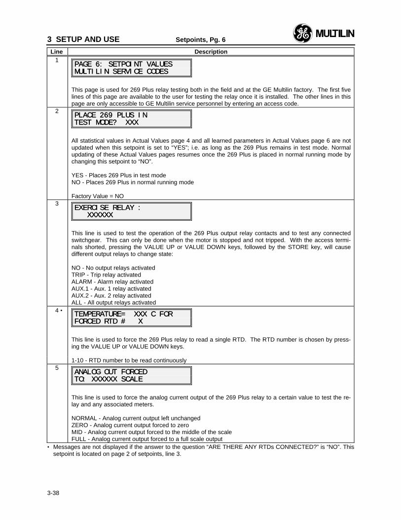
3 SETUP AND USE Setpoints, Pg. 6
Line Description
3-38
1PAGE 6: SETPOINT VALUESPAGE 6: SETPOINT VALUESMULTILIN SERVICE CODESMULTILIN SERVICE CODES
This page is used for 269 Plus relay testing both in the field and at the GE Multilin factory. The first fivelines of this page are available to the user for testing the relay once it is installed. The other lines in thispage are only accessible to GE Multilin service personnel by entering an access code.
2PLACE 269 PLUS INPLACE 269 PLUS INTEST MODE? XXXTEST MODE? XXX
All statistical values in Actual Values page 4 and all learned parameters in Actual Values page 6 are notupdated when this setpoint is set to “YES”; i.e. as long as the 269 Plus remains in test mode. Normalupdating of these Actual Values pages resumes once the 269 Plus is placed in normal running mode bychanging this setpoint to “NO”.
YES - Places 269 Plus in test modeNO - Places 269 Plus in normal running mode
Factory Value = NO3
EXERCISE RELAY :EXERCISE RELAY : XXXXXX XXXXXX
This line is used to test the operation of the 269 Plus output relay contacts and to test any connectedswitchgear. This can only be done when the motor is stopped and not tripped. With the access termi-nals shorted, pressing the VALUE UP or VALUE DOWN keys, followed by the STORE key, will causedifferent output relays to change state:
NO - No output relays activatedTRIP - Trip relay activatedALARM - Alarm relay activatedAUX.1 - Aux. 1 relay activatedAUX.2 - Aux. 2 relay activatedALL - All output relays activated
4 •TEMPERATURE= XXX C FORTEMPERATURE= XXX C FORFORCED RTD # XFORCED RTD # X
This line is used to force the 269 Plus relay to read a single RTD. The RTD number is chosen by press-ing the VALUE UP or VALUE DOWN keys.
1-10 - RTD number to be read continuously5
ANALOG OUT FORCEDANALOG OUT FORCEDTO: XXXXXX SCALETO: XXXXXX SCALE
This line is used to force the analog current output of the 269 Plus relay to a certain value to test the re-lay and any associated meters.
NORMAL - Analog current output left unchangedZERO - Analog current output forced to zeroMID - Analog current output forced to the middle of the scaleFULL - Analog current output forced to a full scale output
• Messages are not displayed if the answer to the question “ARE THERE ANY RTDs CONNECTED?” is “NO”. Thissetpoint is located on page 2 of setpoints, line 3.
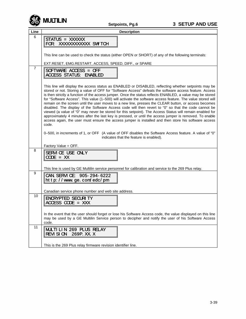
Setpoints, Pg.6 3 SETUP AND USE
Line Description
3-39
6STATUS = XXXXXXSTATUS = XXXXXXFOR: XXXXXXXXXXXX SWITCHFOR: XXXXXXXXXXXX SWITCH
This line can be used to check the status (either OPEN or SHORT) of any of the following terminals:
EXT.RESET, EMG.RESTART, ACCESS, SPEED, DIFF., or SPARE7
SOFTWARE ACCESS = OFFSOFTWARE ACCESS = OFFACCESS STATUS: ENABLEDACCESS STATUS: ENABLED
This line will display the access status as ENABLED or DISABLED, reflecting whether setpoints may bestored or not. Storing a value of OFF for “Software Access” defeats the software access feature. Accessis then strictly a function of the access jumper. Once the status reflects ENABLED, a value may be storedfor “Software Access”. This value (1–500) will activate the software access feature. The value stored willremain on the screen until the user moves to a new line, presses the CLEAR button, or access becomesdisabled. The display of the Software Access code will then revert to “0” so that the code cannot beviewed (a value of “0” may never be stored for this setpoint). The Access Status will remain enabled forapproximately 4 minutes after the last key is pressed, or until the access jumper is removed. To enableaccess again, the user must ensure the access jumper is installed and then store his software accesscode.
0–500, in increments of 1, or OFF (A value of OFF disables the Software Access feature. A value of “0”indicates that the feature is enabled).
Factory Value = OFF.8
SERVICE USE ONLYSERVICE USE ONLYCODE = XXCODE = XX
This line is used by GE Multilin service personnel for calibration and service to the 269 Plus relay.9
CAN.SERVICE: 905-294-6222CAN.SERVICE: 905-294-6222http://www.ge.com/edc/pmhttp://www.ge.com/edc/pm
Canadian service phone number and web site address.10
ENCRYPTED SECURITYENCRYPTED SECURITYACCESS CODE = XXXACCESS CODE = XXX
In the event that the user should forget or lose his Software Access code, the value displayed on this linemay be used by a GE Multilin Service person to decipher and notify the user of his Software Accesscode.
11MULTILIN 269 PLUS RELAYMULTILIN 269 PLUS RELAYREVISION 269P.XX.XREVISION 269P.XX.X
This is the 269 Plus relay firmware revision identifier line.
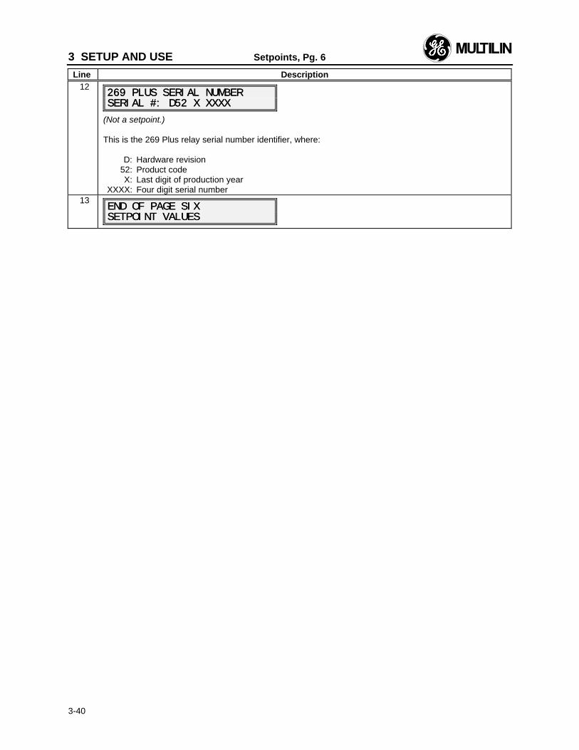
3 SETUP AND USE Setpoints, Pg. 6
Line Description
3-40
12269 PLUS SERIAL NUMBER269 PLUS SERIAL NUMBERSERIAL #: SERIAL #: DD52 X XXXX52 X XXXX
(Not a setpoint.)
This is the 269 Plus relay serial number identifier, where:
D: Hardware revision52: Product codeX: Last digit of production year
XXXX: Four digit serial number13
END OF PAGE SIXEND OF PAGE SIXSETPOINT VALUESSETPOINT VALUES
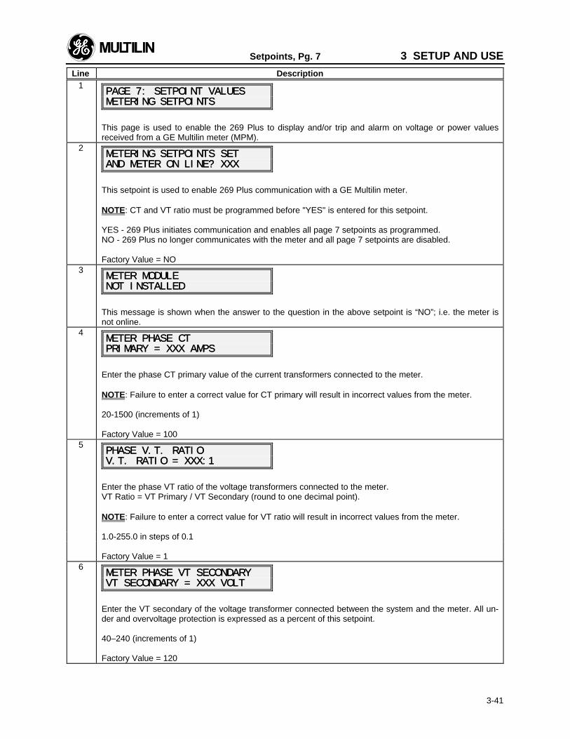
Setpoints, Pg. 7 3 SETUP AND USE
Line Description
3-41
1PAGE 7: SETPOINT VALUESPAGE 7: SETPOINT VALUESMETERING SETPOINTSMETERING SETPOINTS
This page is used to enable the 269 Plus to display and/or trip and alarm on voltage or power valuesreceived from a GE Multilin meter (MPM).
2METERING SETPOINTS SETMETERING SETPOINTS SETAND METER ON LINE? XXXAND METER ON LINE? XXX
This setpoint is used to enable 269 Plus communication with a GE Multilin meter.
NOTE: CT and VT ratio must be programmed before "YES" is entered for this setpoint.
YES - 269 Plus initiates communication and enables all page 7 setpoints as programmed.NO - 269 Plus no longer communicates with the meter and all page 7 setpoints are disabled.
Factory Value = NO3
METER MODULEMETER MODULENOT INSTALLEDNOT INSTALLED
This message is shown when the answer to the question in the above setpoint is “NO”; i.e. the meter isnot online.
4METER PHASE CTMETER PHASE CTPRIMARY = XXX AMPSPRIMARY = XXX AMPS
Enter the phase CT primary value of the current transformers connected to the meter.
NOTE: Failure to enter a correct value for CT primary will result in incorrect values from the meter.
20-1500 (increments of 1)
Factory Value = 1005
PHASE PHASE V.T. RATIOV.T. RATIOV.T. RATIO = XXX:1V.T. RATIO = XXX:1
Enter the phase VT ratio of the voltage transformers connected to the meter.VT Ratio = VT Primary / VT Secondary (round to one decimal point).
NOTE: Failure to enter a correct value for VT ratio will result in incorrect values from the meter.
1.0-255.0 in steps of 0.1
Factory Value = 16
METER PHASE VT SECONDARYMETER PHASE VT SECONDARYVT SECONDARY = XXX VOLTVT SECONDARY = XXX VOLT
Enter the VT secondary of the voltage transformer connected between the system and the meter. All un-der and overvoltage protection is expressed as a percent of this setpoint.
40–240 (increments of 1)
Factory Value = 120
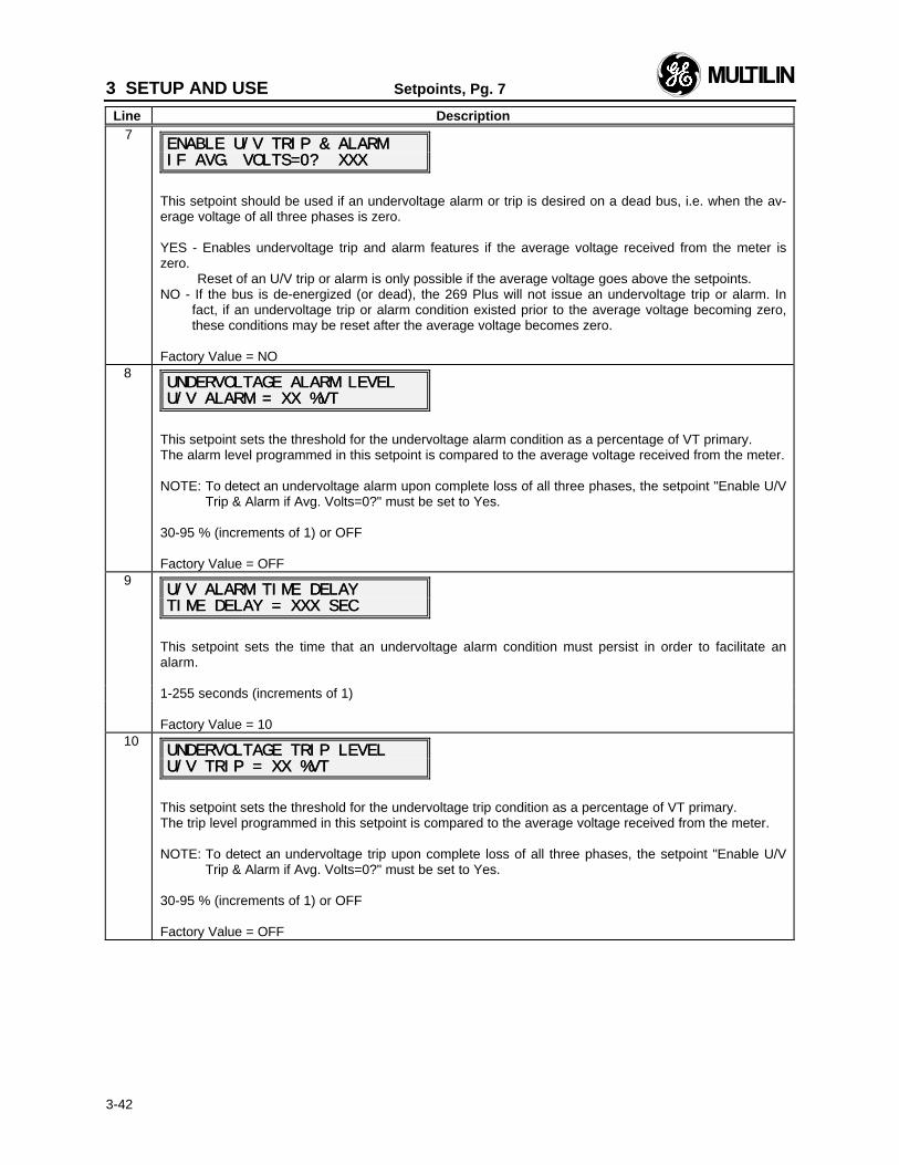
3 SETUP AND USE Setpoints, Pg. 7
Line Description
3-42
7ENABLE U/V TRIP & ALARMENABLE U/V TRIP & ALARMIF AVG. VOLTS=0? XXXIF AVG. VOLTS=0? XXX
This setpoint should be used if an undervoltage alarm or trip is desired on a dead bus, i.e. when the av-erage voltage of all three phases is zero.
YES - Enables undervoltage trip and alarm features if the average voltage received from the meter iszero.
Reset of an U/V trip or alarm is only possible if the average voltage goes above the setpoints.NO - If the bus is de-energized (or dead), the 269 Plus will not issue an undervoltage trip or alarm. In
fact, if an undervoltage trip or alarm condition existed prior to the average voltage becoming zero,these conditions may be reset after the average voltage becomes zero.
Factory Value = NO8
UNDERVOLTAGE ALARM LEVELUNDERVOLTAGE ALARM LEVELU/V ALARM = XX %VTU/V ALARM = XX %VT
This setpoint sets the threshold for the undervoltage alarm condition as a percentage of VT primary.The alarm level programmed in this setpoint is compared to the average voltage received from the meter.
NOTE: To detect an undervoltage alarm upon complete loss of all three phases, the setpoint "Enable U/VTrip & Alarm if Avg. Volts=0?" must be set to Yes.
30-95 % (increments of 1) or OFF
Factory Value = OFF9
U/V ALARM TIME DELAYU/V ALARM TIME DELAYTIME DELAY = XXX SECTIME DELAY = XXX SEC
This setpoint sets the time that an undervoltage alarm condition must persist in order to facilitate analarm.
1-255 seconds (increments of 1)
Factory Value = 1010
UNDERVOLTAGE TRIP LEVELUNDERVOLTAGE TRIP LEVELU/V TRIP = XX %VTU/V TRIP = XX %VT
This setpoint sets the threshold for the undervoltage trip condition as a percentage of VT primary.The trip level programmed in this setpoint is compared to the average voltage received from the meter.
NOTE: To detect an undervoltage trip upon complete loss of all three phases, the setpoint "Enable U/VTrip & Alarm if Avg. Volts=0?" must be set to Yes.
30-95 % (increments of 1) or OFF
Factory Value = OFF
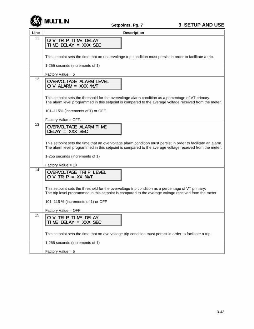
Setpoints, Pg. 7 3 SETUP AND USE
Line Description
3-43
11U/V TRIP TIME DELAYU/V TRIP TIME DELAYTIME DELAY = XXX SECTIME DELAY = XXX SEC
This setpoint sets the time that an undervoltage trip condition must persist in order to facilitate a trip.
1-255 seconds (increments of 1)
Factory Value = 512
OVERVOLTAGE ALARM LEVELOVERVOLTAGE ALARM LEVELO/V ALARM = XXX %VTO/V ALARM = XXX %VT
This setpoint sets the threshold for the overvoltage alarm condition as a percentage of VT primary.The alarm level programmed in this setpoint is compared to the average voltage received from the meter.
101–115% (increments of 1) or OFF.
Factory Value = OFF.13
OVERVOLTAGE ALARM TIMEOVERVOLTAGE ALARM TIMEDELAY = XXX SECDELAY = XXX SEC
This setpoint sets the time that an overvoltage alarm condition must persist in order to facilitate an alarm.The alarm level programmed in this setpoint is compared to the average voltage received from the meter.
1-255 seconds (increments of 1)
Factory Value = 1014
OVERVOLTAGE TRIP LEVELOVERVOLTAGE TRIP LEVELO/V TRIP = XX %VTO/V TRIP = XX %VT
This setpoint sets the threshold for the overvoltage trip condition as a percentage of VT primary.The trip level programmed in this setpoint is compared to the average voltage received from the meter.
101–115 % (increments of 1) or OFF
Factory Value = OFF15
O/V TRIP TIME DELAYO/V TRIP TIME DELAYTIME DELAY = XXX SECTIME DELAY = XXX SEC
This setpoint sets the time that an overvoltage trip condition must persist in order to facilitate a trip.
1-255 seconds (increments of 1)
Factory Value = 5
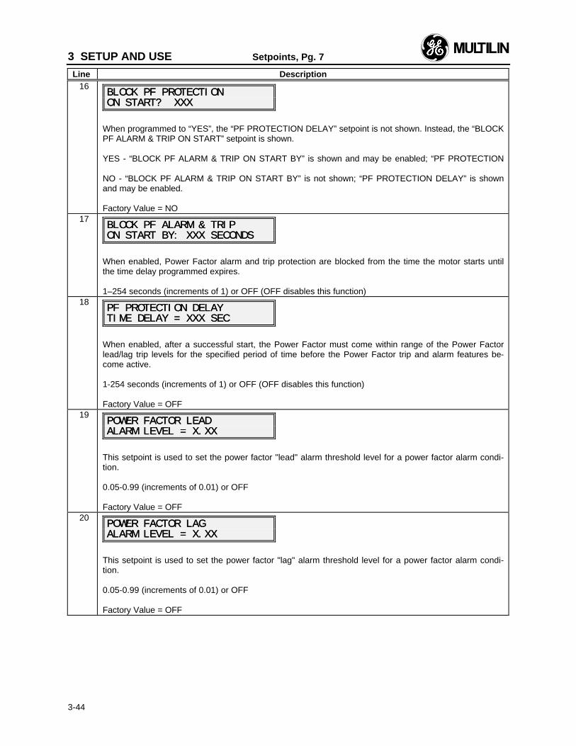
3 SETUP AND USE Setpoints, Pg. 7
Line Description
3-44
16BLOCK PF PROTECTIONBLOCK PF PROTECTIONON START? XXXON START? XXX
When programmed to “YES”, the “PF PROTECTION DELAY” setpoint is not shown. Instead, the “BLOCKPF ALARM & TRIP ON START” setpoint is shown.
YES - “BLOCK PF ALARM & TRIP ON START BY” is shown and may be enabled; “PF PROTECTION
NO - “BLOCK PF ALARM & TRIP ON START BY” is not shown; “PF PROTECTION DELAY” is shownand may be enabled.
Factory Value = NO17
BLOCK PF ALARM & TRIPBLOCK PF ALARM & TRIPON START BY: XXX SECONDSON START BY: XXX SECONDS
When enabled, Power Factor alarm and trip protection are blocked from the time the motor starts untilthe time delay programmed expires.
1–254 seconds (increments of 1) or OFF (OFF disables this function)18
PF PROTECTION DELAYPF PROTECTION DELAYTIME DELAY = XXX SECTIME DELAY = XXX SEC
When enabled, after a successful start, the Power Factor must come within range of the Power Factorlead/lag trip levels for the specified period of time before the Power Factor trip and alarm features be-come active.
1-254 seconds (increments of 1) or OFF (OFF disables this function)
Factory Value = OFF19
POWER FACTOR LEADPOWER FACTOR LEADALARM LEVEL = X.XXALARM LEVEL = X.XX
This setpoint is used to set the power factor "lead" alarm threshold level for a power factor alarm condi-tion.
0.05-0.99 (increments of 0.01) or OFF
Factory Value = OFF20
POWER FACTOR LAGPOWER FACTOR LAGALARM LEVEL = X.XXALARM LEVEL = X.XX
This setpoint is used to set the power factor "lag" alarm threshold level for a power factor alarm condi-tion.
0.05-0.99 (increments of 0.01) or OFF
Factory Value = OFF
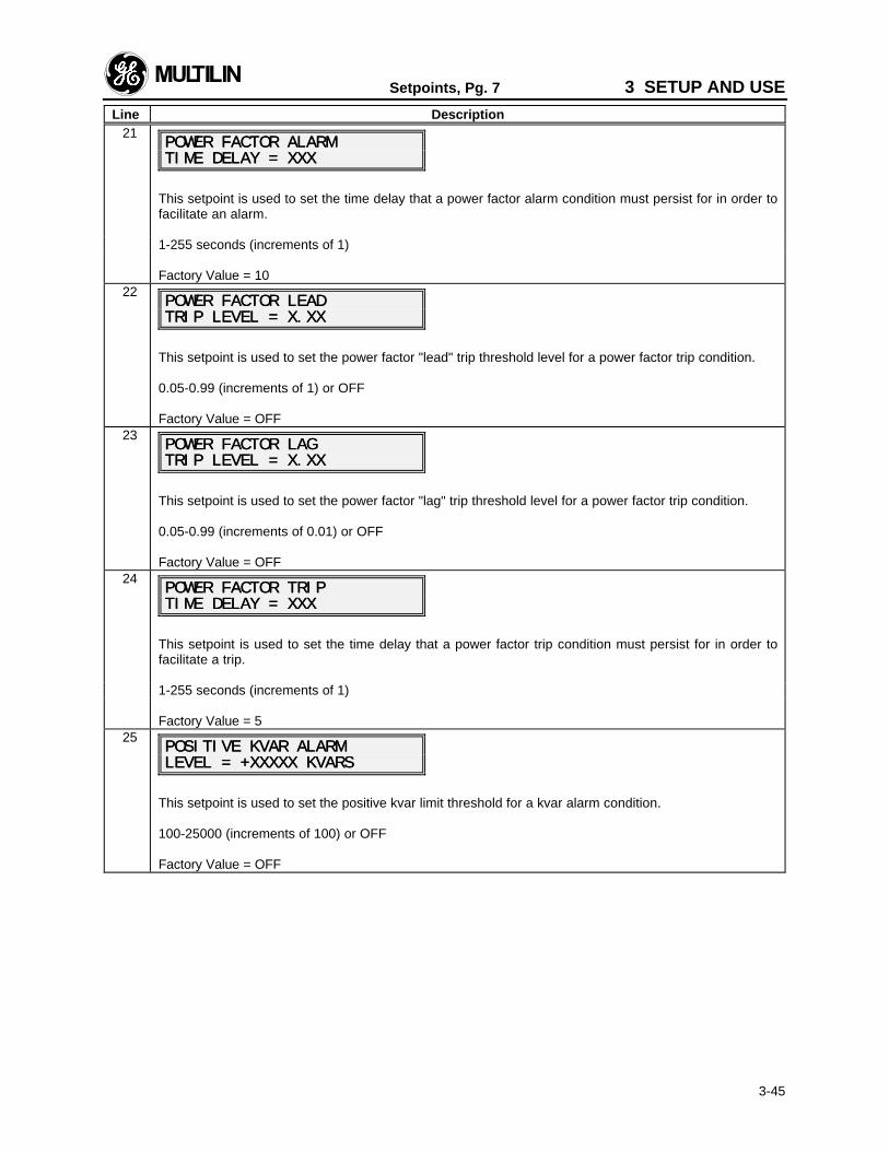
Setpoints, Pg. 7 3 SETUP AND USE
Line Description
3-45
21POWER FACTOR ALARMPOWER FACTOR ALARMTIME DELAY = XXXTIME DELAY = XXX
This setpoint is used to set the time delay that a power factor alarm condition must persist for in order tofacilitate an alarm.
1-255 seconds (increments of 1)
Factory Value = 1022
POWER FACTOR LEADPOWER FACTOR LEADTRIP LEVEL = X.XXTRIP LEVEL = X.XX
This setpoint is used to set the power factor "lead" trip threshold level for a power factor trip condition.
0.05-0.99 (increments of 1) or OFF
Factory Value = OFF23
POWER FACTOR LAGPOWER FACTOR LAGTRIP LEVEL = X.XXTRIP LEVEL = X.XX
This setpoint is used to set the power factor "lag" trip threshold level for a power factor trip condition.
0.05-0.99 (increments of 0.01) or OFF
Factory Value = OFF24
POWER FACTOR TRIPPOWER FACTOR TRIPTIME DELAY = XXXTIME DELAY = XXX
This setpoint is used to set the time delay that a power factor trip condition must persist for in order tofacilitate a trip.
1-255 seconds (increments of 1)
Factory Value = 525
POSITIVE KVAR ALARMPOSITIVE KVAR ALARMLEVEL = +XXXXX LEVEL = +XXXXX KVARSKVARS
This setpoint is used to set the positive kvar limit threshold for a kvar alarm condition.
100-25000 (increments of 100) or OFF
Factory Value = OFF
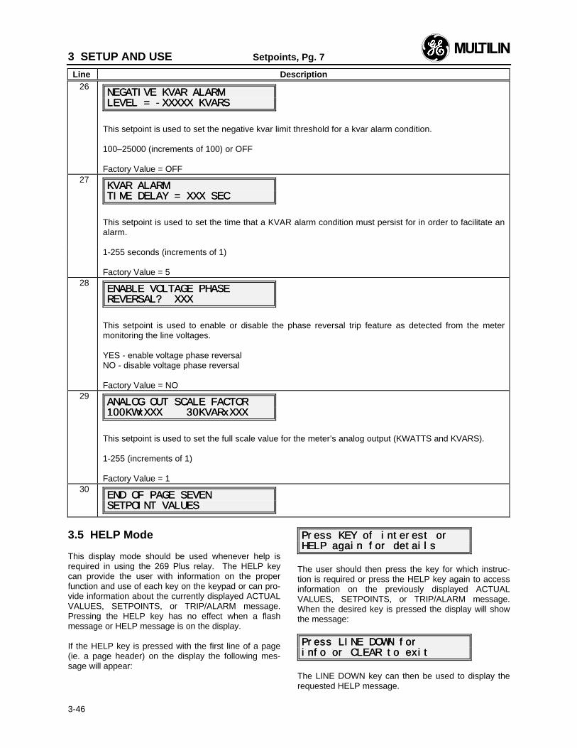
3 SETUP AND USE Setpoints, Pg. 7
Line Description
3-46
26NEGATIVE KVAR ALARMNEGATIVE KVAR ALARMLEVEL = -XXXXX LEVEL = -XXXXX KVARSKVARS
This setpoint is used to set the negative kvar limit threshold for a kvar alarm condition.
100–25000 (increments of 100) or OFF
Factory Value = OFF27
KVAR ALARMKVAR ALARMTIME DELAY = XXX SECTIME DELAY = XXX SEC
This setpoint is used to set the time that a KVAR alarm condition must persist for in order to facilitate analarm.
1-255 seconds (increments of 1)
Factory Value = 528
ENABLE VOLTAGE PHASEENABLE VOLTAGE PHASEREVERSAL? XXXREVERSAL? XXX
This setpoint is used to enable or disable the phase reversal trip feature as detected from the metermonitoring the line voltages.
YES - enable voltage phase reversalNO - disable voltage phase reversal
Factory Value = NO29
ANALOG OUT SCALE FACTORANALOG OUT SCALE FACTOR100KWxXXX 30KVARxXXX100KWxXXX 30KVARxXXX
This setpoint is used to set the full scale value for the meter’s analog output (KWATTS and KVARS).
1-255 (increments of 1)
Factory Value = 130
END OF PAGE SEVENEND OF PAGE SEVENSETPOINT VALUESSETPOINT VALUES
3.5 HELP Mode
This display mode should be used whenever help isrequired in using the 269 Plus relay. The HELP keycan provide the user with information on the properfunction and use of each key on the keypad or can pro-vide information about the currently displayed ACTUALVALUES, SETPOINTS, or TRIP/ALARM message.Pressing the HELP key has no effect when a flashmessage or HELP message is on the display.
If the HELP key is pressed with the first line of a page(ie. a page header) on the display the following mes-sage will appear:
Press KEY of interest orPress KEY of interest orHELP again for detailsHELP again for details
The user should then press the key for which instruc-tion is required or press the HELP key again to accessinformation on the previously displayed ACTUALVALUES, SETPOINTS, or TRIP/ALARM message.When the desired key is pressed the display will showthe message:
Press LINE DOWN forPress LINE DOWN forinfo or CLEAR to exitinfo or CLEAR to exit
The LINE DOWN key can then be used to display therequested HELP message.
3 SETUP AND USE
3-47
If the HELP key is pressed with any line that is not apage header on the display the HELP message shownwill be for the previously displayed ACTUAL VALUES,SETPOINTS, or TRIP/ALARM message.
Pressing the CLEAR key at any time during the HELPmessage will return the display to the page and line ofthe mode in effect when the HELP key was originallypressed. The ACTUAL VALUES and SET POINTSkeys may also be pressed to exit HELP mode.
3.6 TRIP/ALARM Mode
TRIP/ALARM mode can only be entered when a motorvalue exceeds a setpoint value or an alarm becomes ac-tive. Every trip and alarm condition has a separate mes-sage so that the nature of the problem can be identified.
TRIP/ALARM mode will be entered whenever a setpoint isexceeded or an alarm condition arises regardless ofwhether an output relay activation occurs. For example, ifthe "STATOR RTD ALARM LEVEL" setpoint is exceeded,but this function is assigned to "NO" output relay, the 269Plus will enter TRIP/ALARM mode but no output relayactivation will occur.
To leave TRIP/ALARM mode the ACTUAL VALUES, SETPOINTS, or HELP keys can be pressed. Doing this will notchange the state of the output relays but will allow the userto access other motor and relay information to determinethe cause of the trip. The active TRIP/ALARM messagesare found in ACTUAL VALUES mode, page 5, immediatelyin front of the pre-trip motor data. If any trip/alarm functionis active and no key is pressed for a time of 20 seconds,the 269 Plus relay display will return to the appropriateTRIP/ALARM message.
Only one type of relay trip can occur at any one time.However, a trip and an alarm or multiple alarms can occurat the same time. If this is the case the 269 Plus relay dis-play will show the TRIP/ALARM message for the trip oralarm with the highest priority. Any other active messagescan be examined by using the LINE DOWN key. The com-plete set of TRIP/ALARM messages is shown in Table 3-4together with a description of the conditions causing therelay to enter TRIP/ALARM mode. The messages areshown in order of display priority.
• • • • • • • • • • • • • • • • • • • • • • • • • • • • • • • • NOTE: Only one TRIP function or Inhibit can occur atany one time. TRIP functions must therefore be used totrip out the motor. Once one TRIP function or Inhibit isactive no other TRIPs can occur. If multiple ALARMsoccur, the other ALARM messages may be viewed bypressing the LINE DOWN key.
• • • • • • • • • • • • • • • • • • • • • • • • • • • • • • • •
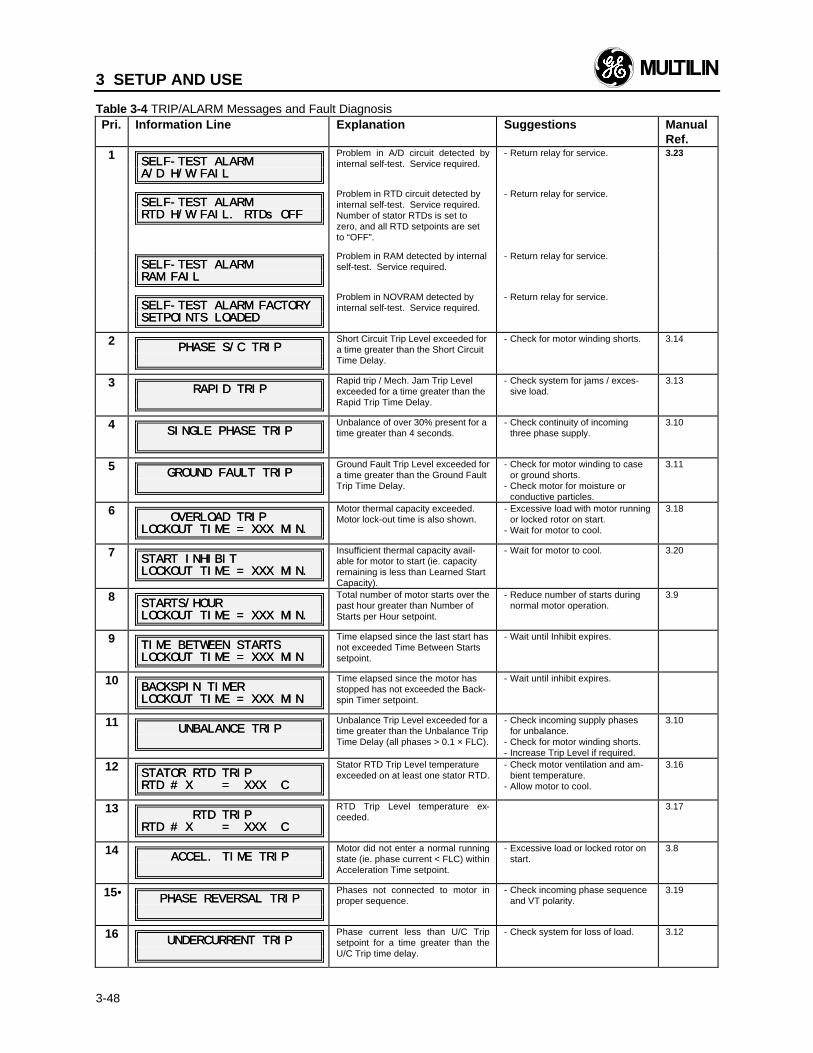
3 SETUP AND USE
3-48
Table 3-4 TRIP/ALARM Messages and Fault DiagnosisPri. Information Line Explanation Suggestions Manual
Ref.1
SELF-TEST ALARMSELF-TEST ALARMA/D H/W FAILA/D H/W FAIL
Problem in A/D circuit detected byinternal self-test. Service required.
- Return relay for service. 3.23
SELF-TEST ALARMSELF-TEST ALARMRTD H/W RTD H/W FAIL. RTDs OFFFAIL. RTDs OFF
Problem in RTD circuit detected byinternal self-test. Service required.Number of stator RTDs is set tozero, and all RTD setpoints are setto “OFF”.
- Return relay for service.
SELF-TEST ALARMSELF-TEST ALARMRAM FAILRAM FAIL
Problem in RAM detected by internalself-test. Service required.
- Return relay for service.
SELF-TEST ALARM FACTORYSELF-TEST ALARM FACTORYSETPOINTS LOADEDSETPOINTS LOADED
Problem in NOVRAM detected byinternal self-test. Service required.
- Return relay for service.
2PHASE S/C TRIPPHASE S/C TRIP
Short Circuit Trip Level exceeded fora time greater than the Short CircuitTime Delay.
- Check for motor winding shorts. 3.14
3RAPID TRIPRAPID TRIP
Rapid trip / Mech. Jam Trip Levelexceeded for a time greater than theRapid Trip Time Delay.
- Check system for jams / exces-sive load.
3.13
4SINGLE PHASE TRIPSINGLE PHASE TRIP
Unbalance of over 30% present for atime greater than 4 seconds.
- Check continuity of incomingthree phase supply.
3.10
5GROUND FAULT TRIPGROUND FAULT TRIP
Ground Fault Trip Level exceeded fora time greater than the Ground FaultTrip Time Delay.
- Check for motor winding to caseor ground shorts.
- Check motor for moisture orconductive particles.
3.11
6 OVERLOAD TRIP OVERLOAD TRIPLOCKOUT TIME = XXX MIN.LOCKOUT TIME = XXX MIN.
Motor thermal capacity exceeded.Motor lock-out time is also shown.
- Excessive load with motor runningor locked rotor on start.
- Wait for motor to cool.
3.18
7START INHIBITSTART INHIBITLOCKOUT TIME = XXX MIN.LOCKOUT TIME = XXX MIN.
Insufficient thermal capacity avail-able for motor to start (ie. capacityremaining is less than Learned StartCapacity).
- Wait for motor to cool. 3.20
8STARTS/HOURSTARTS/HOURLOCKOUT TIME = XXX MIN.LOCKOUT TIME = XXX MIN.
Total number of motor starts over thepast hour greater than Number ofStarts per Hour setpoint.
- Reduce number of starts duringnormal motor operation.
3.9
9TIME BETWEEN STARTSTIME BETWEEN STARTSLOCKOUT TIME = XXX MINLOCKOUT TIME = XXX MIN
Time elapsed since the last start hasnot exceeded Time Between Startssetpoint.
- Wait until Inhibit expires.
10BACKSPIN TIMERBACKSPIN TIMERLOCKOUT TIME = XXX MINLOCKOUT TIME = XXX MIN
Time elapsed since the motor hasstopped has not exceeded the Back-spin Timer setpoint.
- Wait until inhibit expires.
11UNBALANCE TRIPUNBALANCE TRIP
Unbalance Trip Level exceeded for atime greater than the Unbalance TripTime Delay (all phases > 0.1 × FLC).
- Check incoming supply phasesfor unbalance.
- Check for motor winding shorts.- Increase Trip Level if required.
3.10
12STATOR RTD TRIPSTATOR RTD TRIPRTD # X = XXX CRTD # X = XXX C
Stator RTD Trip Level temperatureexceeded on at least one stator RTD.
- Check motor ventilation and am-bient temperature.
- Allow motor to cool.
3.16
13 RTD TRIP RTD TRIPRTD # X = XXX CRTD # X = XXX C
RTD Trip Level temperature ex-ceeded.
3.17
14ACCEL. TIME TRIPACCEL. TIME TRIP
Motor did not enter a normal runningstate (ie. phase current < FLC) withinAcceleration Time setpoint.
- Excessive load or locked rotor onstart.
3.8
15•• PHASE REVERSAL TRIPPHASE REVERSAL TRIPPhases not connected to motor inproper sequence.
- Check incoming phase sequenceand VT polarity.
3.19
16UNDERCURRENT TRIPUNDERCURRENT TRIP
Phase current less than U/C Tripsetpoint for a time greater than theU/C Trip time delay.
- Check system for loss of load. 3.12
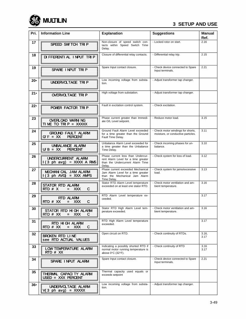
3 SETUP AND USE
3-49
Pri. Information Line Explanation Suggestions ManualRef.
17SPEED SWITCH TRIPSPEED SWITCH TRIP
Non-closure of speed switch con-tacts within Speed Switch TimeDelay.
- Locked rotor on start. 2.16
18DIFFERENTIAL INPUT TRIPDIFFERENTIAL INPUT TRIP
Closure of differential relay contacts. - Differential relay trip. 2.15
19SPARE INPUT TRIPSPARE INPUT TRIP
Spare Input contact closure. - Check device connected to SpareInput terminals.
2.21
20•• UNDERVOLTAGE TRIPUNDERVOLTAGE TRIPLow incoming voltage from substa-tion.
- Adjust transformer tap changer.
21••OVERVOLTAGE TRIPOVERVOLTAGE TRIP
High voltage from substation. - Adjust transformer tap changer.
22•• POWER FACTOR TRIPPOWER FACTOR TRIPFault in excitation control system. - Check excitation.
23 OVERLOAD WARNING OVERLOAD WARNINGTIME TO TRIP = XXXXXTIME TO TRIP = XXXXX
Phase current greater than Immedi-ate O/L Level setpoint.
- Reduce motor load. 3.15
24 GROUND FAULT ALARM GROUND FAULT ALARMG/F = XX PERCENTG/F = XX PERCENT
Ground Fault Alarm Level exceededfor a time greater than the GroundFault Time Delay.
- Check motor windings for shorts,moisture, or conductive particles.
3.11
25 UNBALANCE ALARM UNBALANCE ALARMU/B = XX PERCENTU/B = XX PERCENT
Unbalance Alarm Level exceeded fora time greater than the UnbalanceTime Delay.
- Check incoming phases for un-balance.
3.10
26 UNDERCURRENT ALARM UNDERCURRENT ALARMI(3 I(3 ph ph avg) = XXXX A RMSavg) = XXXX A RMS
Phase current less than Undercur-rent Alarm Level for a time greaterthan the Undercurrent Alarm TimeDelay.
- Check system for loss of load. 3.12
27 MECHANICAL JAM ALARM MECHANICAL JAM ALARMI(3 I(3 ph AVG) = XXX AMPSph AVG) = XXX AMPS
Phase current exceeded MechanicalJam Alarm Level for a time greaterthan the Mechanical Jam AlarmTime Delay.
- Check system for jams/excessiveload.
3.13
28STATOR RTD ALARMSTATOR RTD ALARMRTD # X = XXX CRTD # X = XXX C
Stator RTD Alarm Level temperatureexceeded on at least one stator RTD.
- Check motor ventilation and am-bient temperature.
3.16
29 RTD ALARM RTD ALARMRTD # XX = XXX CRTD # XX = XXX C
RTD Alarm Level temperature ex-ceeded.
3.17
30 STATOR RTD HIGH ALARM STATOR RTD HIGH ALARMRTD # XX = XXX CRTD # XX = XXX C
Stator RTD High Alarm Level tem-perature exceeded.
- Check motor ventilation and am-bient temperature.
3.16
31 RTD HIGH ALARM RTD HIGH ALARMRTD # XX = XXX CRTD # XX = XXX C
RTD High Alarm Level temperatureexceeded.
3.17
32BROKEN RTD LINEBROKEN RTD LINEsee RTD ACTUAL VALUESsee RTD ACTUAL VALUES
Open circuit on RTD. - Check continuity of RTDs. 3.16,3.17
33 LOW TEMPERATURE ALARM LOW TEMPERATURE ALARM RTD # XX RTD # XX
Indicating a possibly shorted RTD ifnormal motor running temperature isabove 0°C (32°F).
- Check continuity of RTD 3.163.17
34SPARE INPUT ALARMSPARE INPUT ALARM
Spare Input contact closure. - Check device connected to SpareInput terminals.
2.21
35THERMAL CAPACITY ALARMTHERMAL CAPACITY ALARMUSED = XXX PERCENTUSED = XXX PERCENT
Thermal capacity used equals orexceeds setpoint
36•• UNDERVOLTAGE ALARM UNDERVOLTAGE ALARMV(3 V(3 ph ph avg) = XXXXXavg) = XXXXX
Low incoming voltage from substa-tion.
- Adjust transformer tap changer.
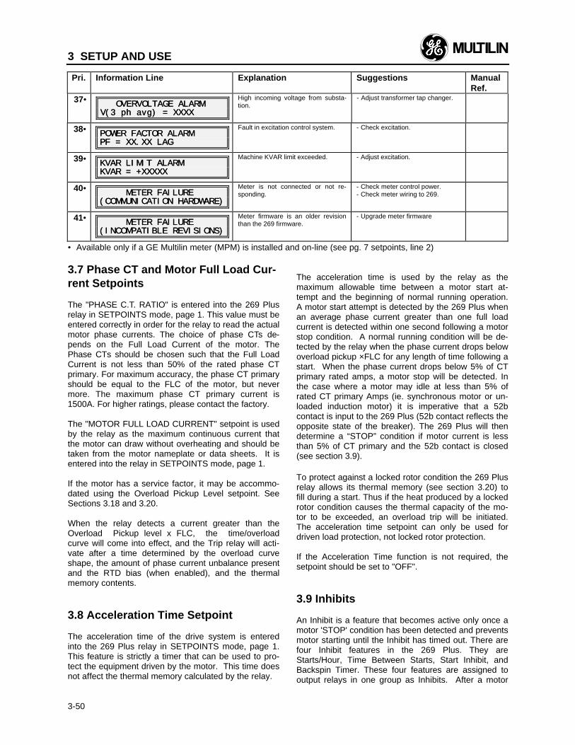
3 SETUP AND USE
3-50
Pri. Information Line Explanation Suggestions ManualRef.
37•• OVERVOLTAGE ALARM OVERVOLTAGE ALARMV(3 V(3 ph ph avg) = XXXXavg) = XXXX
High incoming voltage from substa-tion.
- Adjust transformer tap changer.
38•• POWER FACTOR ALARMPOWER FACTOR ALARMPF = XX.XX LAGPF = XX.XX LAG
Fault in excitation control system. - Check excitation.
39•• KVAR LIMIT ALARMKVAR LIMIT ALARMKVAR = +XXXXXKVAR = +XXXXX
Machine KVAR limit exceeded. - Adjust excitation.
40•• METER FAILURE METER FAILURE(COMMUNICATION HARDWARE)(COMMUNICATION HARDWARE)
Meter is not connected or not re-sponding.
- Check meter control power.- Check meter wiring to 269.
41•• METER FAILURE METER FAILURE(INCOMPATIBLE REVISIONS)(INCOMPATIBLE REVISIONS)
Meter firmware is an older revisionthan the 269 firmware.
- Upgrade meter firmware
•• Available only if a GE Multilin meter (MPM) is installed and on-line (see pg. 7 setpoints, line 2)
3.7 Phase CT and Motor Full Load Cur-rent Setpoints
The "PHASE C.T. RATIO" is entered into the 269 Plusrelay in SETPOINTS mode, page 1. This value must beentered correctly in order for the relay to read the actualmotor phase currents. The choice of phase CTs de-pends on the Full Load Current of the motor. ThePhase CTs should be chosen such that the Full LoadCurrent is not less than 50% of the rated phase CTprimary. For maximum accuracy, the phase CT primaryshould be equal to the FLC of the motor, but nevermore. The maximum phase CT primary current is1500A. For higher ratings, please contact the factory.
The "MOTOR FULL LOAD CURRENT" setpoint is usedby the relay as the maximum continuous current thatthe motor can draw without overheating and should betaken from the motor nameplate or data sheets. It isentered into the relay in SETPOINTS mode, page 1.
If the motor has a service factor, it may be accommo-dated using the Overload Pickup Level setpoint. SeeSections 3.18 and 3.20.
When the relay detects a current greater than theOverload Pickup level x FLC, the time/overloadcurve will come into effect, and the Trip relay will acti-vate after a time determined by the overload curveshape, the amount of phase current unbalance presentand the RTD bias (when enabled), and the thermalmemory contents.
3.8 Acceleration Time Setpoint
The acceleration time of the drive system is enteredinto the 269 Plus relay in SETPOINTS mode, page 1.This feature is strictly a timer that can be used to pro-tect the equipment driven by the motor. This time doesnot affect the thermal memory calculated by the relay.
The acceleration time is used by the relay as themaximum allowable time between a motor start at-tempt and the beginning of normal running operation.A motor start attempt is detected by the 269 Plus whenan average phase current greater than one full loadcurrent is detected within one second following a motorstop condition. A normal running condition will be de-tected by the relay when the phase current drops belowoverload pickup ×FLC for any length of time following astart. When the phase current drops below 5% of CTprimary rated amps, a motor stop will be detected. Inthe case where a motor may idle at less than 5% ofrated CT primary Amps (ie. synchronous motor or un-loaded induction motor) it is imperative that a 52bcontact is input to the 269 Plus (52b contact reflects theopposite state of the breaker). The 269 Plus will thendetermine a “STOP” condition if motor current is lessthan 5% of CT primary and the 52b contact is closed(see section 3.9).
To protect against a locked rotor condition the 269 Plusrelay allows its thermal memory (see section 3.20) tofill during a start. Thus if the heat produced by a lockedrotor condition causes the thermal capacity of the mo-tor to be exceeded, an overload trip will be initiated.The acceleration time setpoint can only be used fordriven load protection, not locked rotor protection.
If the Acceleration Time function is not required, thesetpoint should be set to "OFF".
3.9 Inhibits
An Inhibit is a feature that becomes active only once amotor 'STOP' condition has been detected and preventsmotor starting until the Inhibit has timed out. There arefour Inhibit features in the 269 Plus. They areStarts/Hour, Time Between Starts, Start Inhibit, andBackspin Timer. These four features are assigned tooutput relays in one group as Inhibits. After a motor
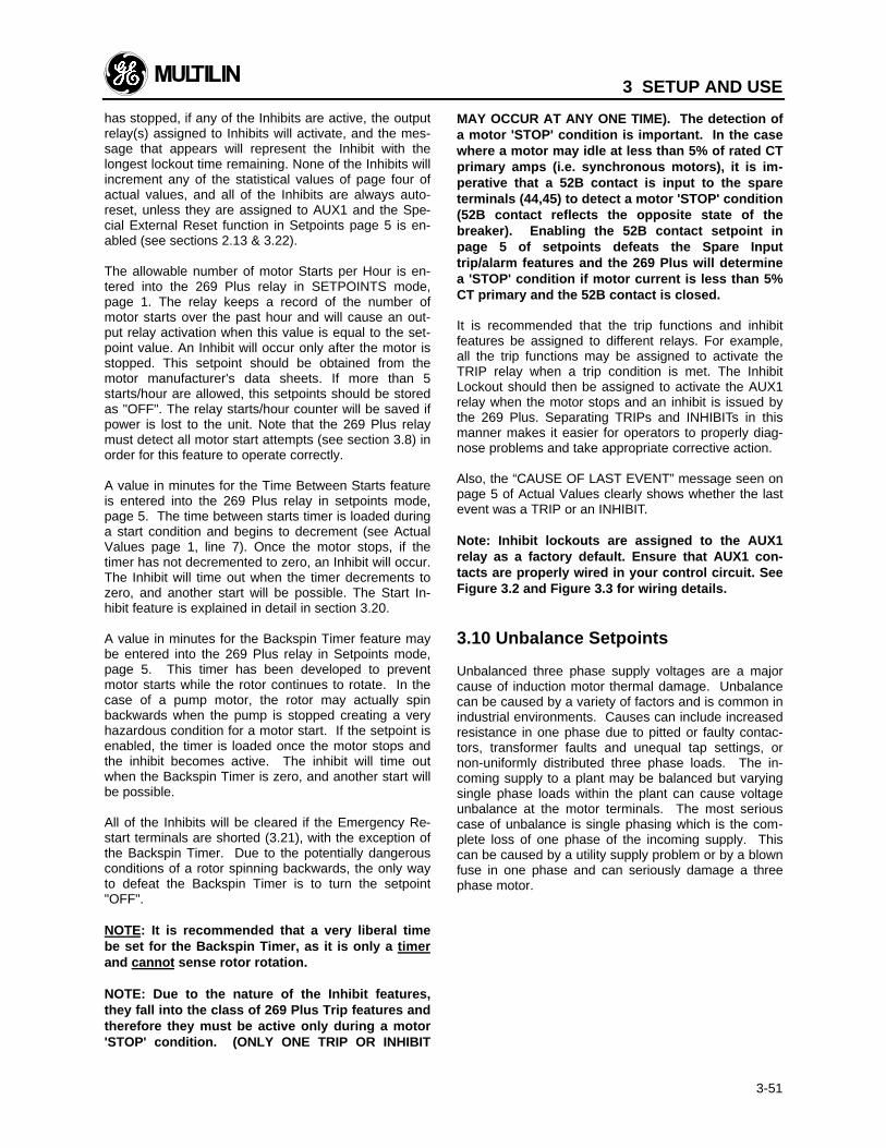
3 SETUP AND USE
3-51
has stopped, if any of the Inhibits are active, the outputrelay(s) assigned to Inhibits will activate, and the mes-sage that appears will represent the Inhibit with thelongest lockout time remaining. None of the Inhibits willincrement any of the statistical values of page four ofactual values, and all of the Inhibits are always auto-reset, unless they are assigned to AUX1 and the Spe-cial External Reset function in Setpoints page 5 is en-abled (see sections 2.13 & 3.22).
The allowable number of motor Starts per Hour is en-tered into the 269 Plus relay in SETPOINTS mode,page 1. The relay keeps a record of the number ofmotor starts over the past hour and will cause an out-put relay activation when this value is equal to the set-point value. An Inhibit will occur only after the motor isstopped. This setpoint should be obtained from themotor manufacturer's data sheets. If more than 5starts/hour are allowed, this setpoints should be storedas "OFF". The relay starts/hour counter will be saved ifpower is lost to the unit. Note that the 269 Plus relaymust detect all motor start attempts (see section 3.8) inorder for this feature to operate correctly.
A value in minutes for the Time Between Starts featureis entered into the 269 Plus relay in setpoints mode,page 5. The time between starts timer is loaded duringa start condition and begins to decrement (see ActualValues page 1, line 7). Once the motor stops, if thetimer has not decremented to zero, an Inhibit will occur.The Inhibit will time out when the timer decrements tozero, and another start will be possible. The Start In-hibit feature is explained in detail in section 3.20.
A value in minutes for the Backspin Timer feature maybe entered into the 269 Plus relay in Setpoints mode,page 5. This timer has been developed to preventmotor starts while the rotor continues to rotate. In thecase of a pump motor, the rotor may actually spinbackwards when the pump is stopped creating a veryhazardous condition for a motor start. If the setpoint isenabled, the timer is loaded once the motor stops andthe inhibit becomes active. The inhibit will time outwhen the Backspin Timer is zero, and another start willbe possible.
All of the Inhibits will be cleared if the Emergency Re-start terminals are shorted (3.21), with the exception ofthe Backspin Timer. Due to the potentially dangerousconditions of a rotor spinning backwards, the only wayto defeat the Backspin Timer is to turn the setpoint"OFF".
NOTE: It is recommended that a very liberal timebe set for the Backspin Timer, as it is only a timerand cannot sense rotor rotation.
NOTE: Due to the nature of the Inhibit features,they fall into the class of 269 Plus Trip features andtherefore they must be active only during a motor'STOP' condition. (ONLY ONE TRIP OR INHIBIT
MAY OCCUR AT ANY ONE TIME). The detection ofa motor 'STOP' condition is important. In the casewhere a motor may idle at less than 5% of rated CTprimary amps (i.e. synchronous motors), it is im-perative that a 52B contact is input to the spareterminals (44,45) to detect a motor 'STOP' condition(52B contact reflects the opposite state of thebreaker). Enabling the 52B contact setpoint inpage 5 of setpoints defeats the Spare Inputtrip/alarm features and the 269 Plus will determinea 'STOP' condition if motor current is less than 5%CT primary and the 52B contact is closed.
It is recommended that the trip functions and inhibitfeatures be assigned to different relays. For example,all the trip functions may be assigned to activate theTRIP relay when a trip condition is met. The InhibitLockout should then be assigned to activate the AUX1relay when the motor stops and an inhibit is issued bythe 269 Plus. Separating TRIPs and INHIBITs in thismanner makes it easier for operators to properly diag-nose problems and take appropriate corrective action.
Also, the “CAUSE OF LAST EVENT” message seen onpage 5 of Actual Values clearly shows whether the lastevent was a TRIP or an INHIBIT.
Note: Inhibit lockouts are assigned to the AUX1relay as a factory default. Ensure that AUX1 con-tacts are properly wired in your control circuit. SeeFigure 3.2 and Figure 3.3 for wiring details.
3.10 Unbalance Setpoints
Unbalanced three phase supply voltages are a majorcause of induction motor thermal damage. Unbalancecan be caused by a variety of factors and is common inindustrial environments. Causes can include increasedresistance in one phase due to pitted or faulty contac-tors, transformer faults and unequal tap settings, ornon-uniformly distributed three phase loads. The in-coming supply to a plant may be balanced but varyingsingle phase loads within the plant can cause voltageunbalance at the motor terminals. The most seriouscase of unbalance is single phasing which is the com-plete loss of one phase of the incoming supply. Thiscan be caused by a utility supply problem or by a blownfuse in one phase and can seriously damage a threephase motor.
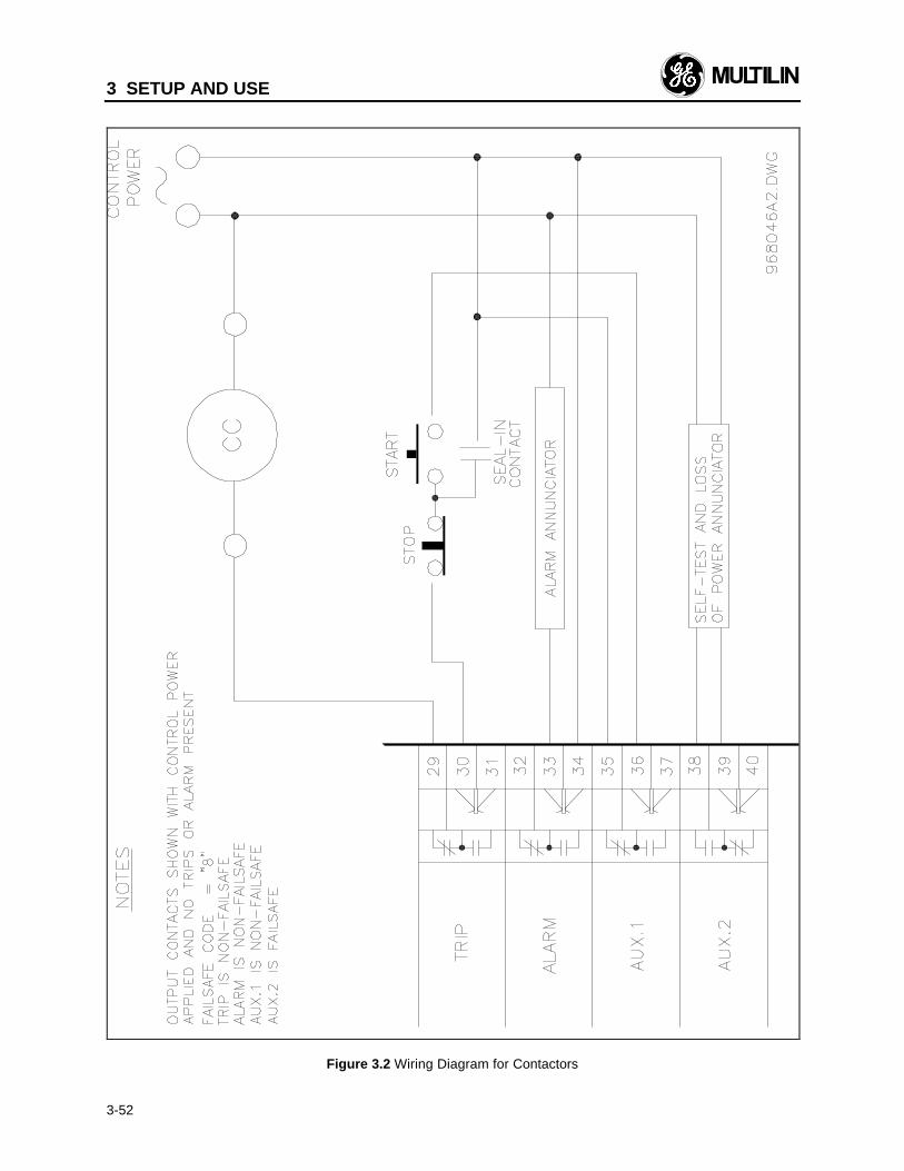
3 SETUP AND USE
3-52
Figure 3.2 Wiring Diagram for Contactors
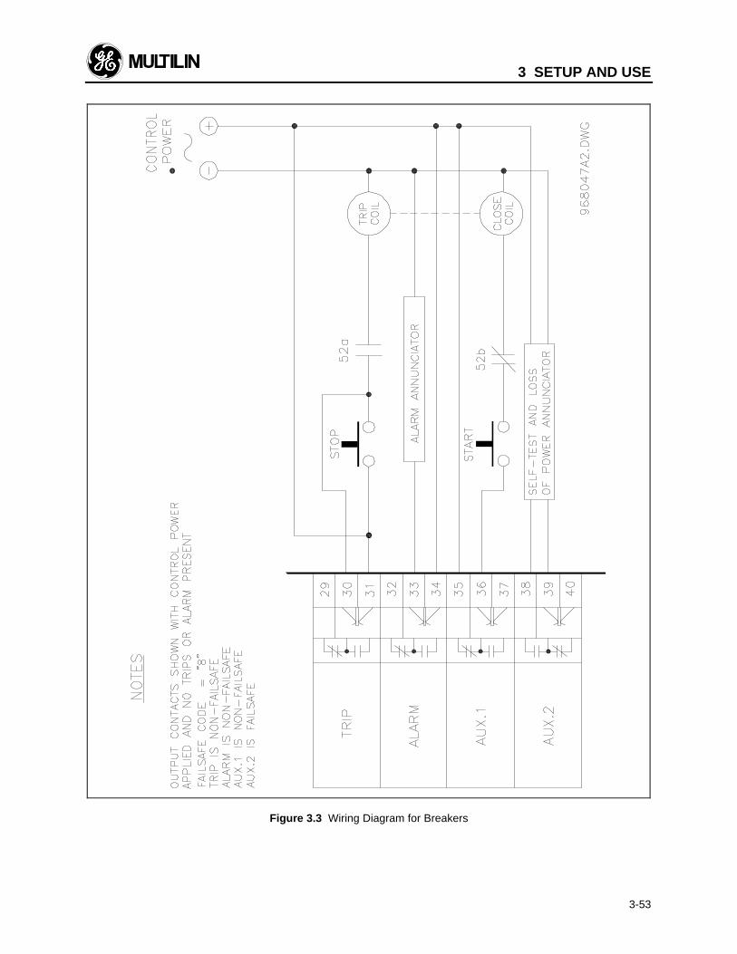
3 SETUP AND USE
3-53
Figure 3.3 Wiring Diagram for Breakers
3 SETUP AND USE
3-54
Unbalance at the motor terminals means an increase inthe applied negative sequence voltage. This results ina large increase in the negative sequence currentdrawn by the motor due to the relatively small negativesequence impedance of the rotor. This current is nor-mally at about twice the power supply frequency andproduces a torque in the opposite direction to the de-sired motor output. For small unbalances the overalloutput torque will remain constant, but the motor will bedeveloping a large positive torque to overcome thenegative sequence torque. These opposing torques andthe high negative sequence current produce muchhigher rotor losses and consequently greatly increasedrotor heating effects. Stator heating is increased aswell, but to a much smaller extent. The amount of un-balance that a given motor can tolerate is thereforedependent on the rotor design and heat dissipationcharacteristics.
Persistent, minor voltage unbalance can thus lead torotor thermal damage while severe unbalance such assingle phasing can very quickly lead to a motor burn-out.
For phase currents above 100% FLC, the 269 Plusrelay calculates the ratio of the negative to positive se-quence currents (In/Ip) and uses this ratio in two sepa-rate protective functions. It is used to bias the thermalmemory of the relay which represents the thermal ca-pacity of the motor as a whole (this can be enabled inSETPOINTS mode, page 5), and it is used for separateunbalance protection. The method of determining In/Ipis independent of actual line frequency or phase currentlead/lag characteristics, and when enabled is used tobias the thermal memory (see section 3.20). Thisnegative sequence unbalance method provides read-ings similar to the NEMA unbalance calculation butgives more realistic results for the thermal effect ofunbalance on the motor (for a 269 Plus unbalance ex-ample, see Appendix A). For phase currents below100% FLC, the relay calculates the ratio of In to fullload current (In/IFLC) and uses this to provide pro-tection. This avoids nuisance trips due to relatively highlevels of In with lower levels of Ip that may create highU/B levels at low loads.
For unbalance protection, trip and alarm In/Ip ratiosmay be chosen along with appropriate persistencetimes (time delays) in SETPOINTS mode, page 1. If nounbalance protection is desired, the trip and alarm lev-els should be set to "OFF". The delay times will then bedisregarded by the relay. Above 100% FLC, if an un-balance of more than 30% persists for more than 4seconds, a "SINGLE PHASE TRIP" will result. Below100% FLC, if motor load is >25%, and any one phasereads zero, this will also be considered a single phasecondition. The single phase time delay may be adjustedby contacting the factory.
Note: If the "UNBALANCE TRIP LEVEL" is set to"OFF," single phase protection will be turned off.
It should be noted that a 1% voltage unbalance typi-cally translates into a 6% current unbalance. So, if forexample the supply voltage is normally unbalanced upto 2%, the current unbalance seen by a typical motorwould be 2×6 = 12%. Set the alarm pickup at 15% andthe trip at 20% to prevent nuisance tripping. 5 or 10seconds is a reasonable delay.
Other factors may produce unbalanced phase currents.Cyclic, pulsating and rapidly changing loads have beenobserved to create unbalance in machines such as ballmill grinders, shredders, crushers, and centrifugalcompressors, where the load characteristics are con-stantly and rapidly changing.
Under such circumstances, and in order to preventnuisance unbalance trips or alarms, the pickup levelshould not be set too low. Also, a reasonable time de-lay should be set to avoid nuisance trips or alarms. It isrecommended that the unbalance input to thermalmemory be used to bias the thermal model, thus ac-counting for motor heating that may be caused by cy-clic short term unbalances.
3.11 Ground Fault (Earth Leakage) Set-points
Aging and thermal cycling can eventually cause a low-ering of the dielectric strength of the insulation in thestator winding. This can produce a low impedance pathfrom the supply to ground resulting in ground fault cur-rents which can be quite high in solidly grounded sys-tems. In resistance grounded systems there is aresistance in series with the supply source to limitground fault current and allow the system to continueoperating for a short time under fault conditions. Thefault should be located and corrected as soon as pos-sible, however, since a second fault on another phasewould result in a very high current flow. In addition todamaging the motor, a ground fault can place the mo-tor casing above ground potential thus presenting asafety hazard to personnel.
On the occurrence of a ground fault caused by insula-tion breakdown, an unprotected motor will commonlysuffer severe structural damage and have to be re-placed. The fault could also shut down the power sup-ply bus to which the faulty motor is connected.
Ground faults can occur in otherwise good motors be-cause of environmental conditions. Moisture or con-ductive dust, which are often present in mines, canprovide an electrical path to ground thus allowingground fault current to flow. In this case, ground faultprotection should shut down the motor immediately sothat it can be dried or cleaned before being restarted.
For ground fault protection by the 269 Plus relay, allthree of the motor conductors must pass through aseparate ground fault CT (see section 2.6). The CT
3 SETUP AND USE
3-55
may be either GE Multilin’s 50:0.025A (2000:1 ratio) or20:5 up to 1500:5 and is chosen in SETPOINTS mode,page 1. Separate ground fault trip and alarm levels(entered in actual ground fault amps), and persistencetimes (time delays) may also be set. The ground faulttrip can be instantaneous, or up to 20.0 seconds oftime delay can be chosen to allow the 269 Plus relay tobe coordinated with other protective devices andswitchgear.
The amount of current that will flow due to a fault de-pends on where the fault occurs in the motor winding.A high current flow will result if a short to ground oc-curs near the end of the stator winding nearest the ter-minal voltage. A low ground fault current will flow if afault occurs at the neutral end of the winding since thisend should be a virtual ground. Thus a low level ofground fault pickup is desirable to protect as much ofthe stator winding as possible and to prevent the motorcasing from becoming a shock hazard. In resistancegrounded systems the ground fault trip level must beset below the maximum current limited by the groundresistor or else the relay will not see a large enoughground fault current to cause a trip.
The ground fault trip level should be set as low as pos-sible, although too sensitive a setting may cause nui-sance trips due to capacitive current flow. If nuisancetrips occur with no apparent cause the trip level shouldbe increased; conversely if no nuisance trips occur alower fault setpoint may be desirable.
CAUTION: Care must be taken when turning on thisfeature. If the interrupting device (circuit breaker orcontactor) is not rated to break ground fault current(low resistance or solidly grounded systems), the tripsetpoint should be set to “OFF”. The feature may beassigned to the AUX1 relay and connected such that ittrips an upstream device that is capable of breaking thefault current.
3.12 Undercurrent Setpoints
These setpoints are found in SETPOINTS mode, page1 and are normally used to detect a decrease in motorcurrent flow caused by a loss of, or decrease in, motorload. This is especially useful for indication of loss ofsuction for pumps, loss of airflow for fans, or a brokenbelt for conveyors. When the current falls below thesetpoint value for the setpoint time, the relay assignedto the undercurrent trip or alarm function will becomeactive.
If this feature is used for loss of load detection, the"UNDERCURRENT ALARM LEVEL" or“UNDERCURRENT TRIP LEVEL” setpoints should bechosen to be just above the motor current level for theanticipated reduced load condition. If the feature is notdesired, the alarm and trip levels should be set to
"OFF". The delay time setpoints will then be ignored bythe relay.
If the motor is normally operated at a current level be-low its rated full load current, this feature may be usedfor a pre-overload warning. This is accomplished bysetting the "UNDERCURRENT ALARM LEVEL" to beabove the normal operating current of the motor butbelow the rated full load current. In this way the under-current function will cause the relay assigned to it tobecome inactive if the motor current increases abovethe Undercurrent setpoint level. This would indicate anabnormal loading condition prior to an actual motoroverload.
The output relay assigned to the undercurrent alarmfunction will automatically reset itself when the motorstops (i.e. when the phase current becomes zero) un-less this relay is programmed as latched (see "RELAYALARM LATCHCODE", SETPOINTS, page 5).
The undercurrent trip function is always latched and areset is required to clear the trip.
3.13 Rapid Trip / Mechanical Jam Set-points
These setpoints are found in SETPOINTS mode, page1 and are used to protect the driven mechanical systemfrom jams. If used, this feature is active only after themotor has successfully started, and will cause relayactivation in the event of a stall while the motor is run-ning.
A current surge of 150% to 600% of motor full loadfrom 0.5 to 125.0 seconds during motor operation, de-pending on the setpoints chosen, will cause the relayassigned to the Rapid Trip or Mechanical Jam alarmfunctions to become active. To disable the Rapid Trip orMechanical Jam alarm functions, the "RAPIDTRIP/MECH. JAM TRIP LEVEL" or “MECHANICALJAM ALARM LEVEL” setpoint should be set to "OFF".The "RAPID TRIP TIME DELAY" and “MECHANICALJAM ALARM TIME DELAY” setpoints will then be disre-garded by the relay.
Note: These features are not recommended for usewith systems that experience overloads as part ofnormal operation.
3.14 Short Circuit Setpoints
The Short Circuit protective function provides overridingprotection for any large phase current. Complete pro-tection from phase-to-phase and phase-to-groundfaults is provided with this feature. This feature is ac-tive at all times, including during motor starts, unless
3 SETUP AND USE
3-56
the "SHORT CIRCUIT TRIP LEVEL" is set to OFF. Thesetpoints are in SETPOINTS mode, page 1.
The phase current short circuit trip level can be setfrom 4 to 12 times motor full load current. The trip canbe instantaneous or can be delayed by up to 20.5 sec-onds to facilitate coordination with system switchgear.If this feature is not desired the "SHORT CIRCUIT TRIPLEVEL" setpoint should be set to "OFF". If this is donethe relay will disregard the "SHORT CIRCUIT TIMEDELAY" setpoint.
CAUTION: When using this feature be certain thatthe interrupting device can safely open to break theshort circuit duty. Otherwise this setpoint must beset to OFF. Other means of interrupting fault cur-rents must then be used (e.g. fuses).
3.15 Immediate Overload Alarm LevelSetpoint
The Immediate Overload Alarm Level setpoint is foundin SETPOINTS mode, page 1. It is adjustable from1.01 ×FLC to 1.50 ×FLC. An output relay activation willoccur immediately when the average phase currentgoes over the setpoint value. This function can nevercause latched (manual reset) relay operation.
An Immediate Overload Alarm will not be issued whenthe motor is started. This function is only active whenthe motor is in the run mode.
3.16 Stator RTD Setpoints
The 269 Plus is ordered with one of the following RTDtypes: 100 ohm platinum, 10 ohm copper, 100 ohmnickel, or 120 ohm nickel. A message on page 2 ofSetpoints may be examined to determine the type ofRTD built into the relay.
It is possible to operate the 269 Plus without connect-ing any RTDs to it. A setpoint on page 2 of Setpointsasks the question:
ARE THERE ANY RTDsARE THERE ANY RTDsCONNECTED? NOCONNECTED? NO
if the answer is “NO”, the 269 Plus hides all RTD re-lated Setpoints and Actual Values thus making it easierto program for the application.
The 269 Plus relay displays temperatures in either Cel-sius or Fahrenheit depending on the RTD MessageDisplay setpoint. If Fahrenheit option is chosen theincrement can vary between 1 and 2 due to the conver-sion from Celsius to Fahrenheit and the rounding of theresult. NOTE: RTD temperature values are available onthe RS485 communications port in Celsius only, even if
the Fahrenheit option is chosen. NOTE: CARE MUSTBE TAKEN NOT TO ENTER CELSIUS VALUES FORSETPOINT PARAMETERS WHEN IN FAHRENHEITMODE AND VICE-VERSA.
The 269 Plus relay has 6 sets of 4 terminals availablefor the connection of RTDs to monitor the temperatureof the stator windings. If fewer than 6 RTDs are to beused they must be connected to the lowest numberedRTD connections on the rear of the relay. The statorRTD setpoints are found in SETPOINTS mode, page 2.The "# OF STATOR RTDS USED" setpoint should bechosen to represent the number of RTDs actually con-nected to the motor stator windings. Thus if 3 RTDsare connected to the stator, the "# OF STATOR RTDSUSED" setpoint should be set to 3, and the 3 RTDsmust be connected to the terminals for RTD1, RTD2,and RTD3 (terminals #1-12).
There are individual trip, alarm, and high alarm set-points for each stator, and trip and alarm setpoints forother (eg. bearing) RTDs. For stator RTDs a TRIP relayactivation will occur when at least two stator RTDs goover their corresponding setpoints. This is the casewhen the “Stator RTD Voting” scheme is in effect. OtherRTDs are not affected by the voting feature. Trip relayactivation for other RTDs will occur when any one ofthe RTD temperatures goes over its setpoint value. Thisis also the case for stator RTDs if voting is defeated.Stator RTD Alarms and High Alarms, and other RTDAlarms are also issued based on individual RTD set-points. The maximum stator RTD temperature at anytime will be used for relay thermal calculation.
When the relay is in ACTUAL VALUES mode the tem-perature readings from all of the RTDs may be dis-played. If no connection has been made to any RTDterminals, the display for that RTD will be "no RTD". Ifthe answer to the question “ARE THERE ANY RTDsCONNECTED?” is “NO”, the display will show “NORTDs ARE CONNECTED TO THE 269PLUS”. If the "#OF STATOR RTDS USED" setpoint is stored as 3, onlythe maximum temperature from RTD1, RTD2, andRTD3 will be used for motor temperature calculations.Thus, in this case, RTD4, RTD5, and RTD6 may beused for any other RTD temperature monitoring func-tion desired.
If a stator RTD becomes open circuited during use, theACTUAL VALUES display for that RTD will be "noRTD". Readings from the disconnected RTD will thenbe ignored. The 269 Plus relay will enter TRIP/ALARMmode to warn the user of the faulty RTD if the "No Sen-sor Alarm" is enabled (SETPOINTS, page 5). Similarly,if the “Low Temperature Alarm” is enabled (Setpoints,page 5) the relay will enter Trip/Alarm mode to warn theuser of any one RTD measuring 0°C (32°F). This set-point can be used to detect shorted RTDs given that thenormal running temperature of the motor’s stator,bearing and other RTDs is not 0°C or less. After a sta-tor RTD temperature trip, alarm, or high alarm setpoint
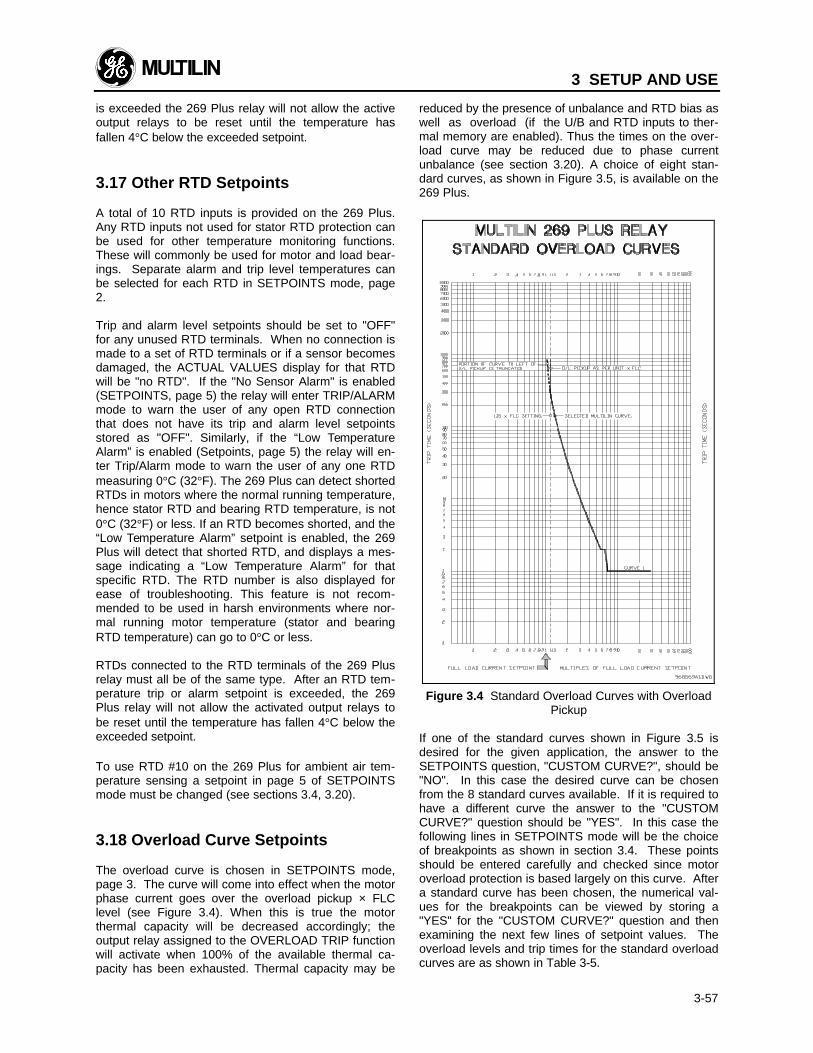
3 SETUP AND USE
3-57
is exceeded the 269 Plus relay will not allow the activeoutput relays to be reset until the temperature hasfallen 4°C below the exceeded setpoint.
3.17 Other RTD Setpoints
A total of 10 RTD inputs is provided on the 269 Plus.Any RTD inputs not used for stator RTD protection canbe used for other temperature monitoring functions.These will commonly be used for motor and load bear-ings. Separate alarm and trip level temperatures canbe selected for each RTD in SETPOINTS mode, page2.
Trip and alarm level setpoints should be set to "OFF"for any unused RTD terminals. When no connection ismade to a set of RTD terminals or if a sensor becomesdamaged, the ACTUAL VALUES display for that RTDwill be "no RTD". If the "No Sensor Alarm" is enabled(SETPOINTS, page 5) the relay will enter TRIP/ALARMmode to warn the user of any open RTD connectionthat does not have its trip and alarm level setpointsstored as "OFF". Similarly, if the “Low TemperatureAlarm” is enabled (Setpoints, page 5) the relay will en-ter Trip/Alarm mode to warn the user of any one RTDmeasuring 0°C (32°F). The 269 Plus can detect shortedRTDs in motors where the normal running temperature,hence stator RTD and bearing RTD temperature, is not0°C (32°F) or less. If an RTD becomes shorted, and the“Low Temperature Alarm” setpoint is enabled, the 269Plus will detect that shorted RTD, and displays a mes-sage indicating a “Low Temperature Alarm” for thatspecific RTD. The RTD number is also displayed forease of troubleshooting. This feature is not recom-mended to be used in harsh environments where nor-mal running motor temperature (stator and bearingRTD temperature) can go to 0°C or less.
RTDs connected to the RTD terminals of the 269 Plusrelay must all be of the same type. After an RTD tem-perature trip or alarm setpoint is exceeded, the 269Plus relay will not allow the activated output relays tobe reset until the temperature has fallen 4°C below theexceeded setpoint.
To use RTD #10 on the 269 Plus for ambient air tem-perature sensing a setpoint in page 5 of SETPOINTSmode must be changed (see sections 3.4, 3.20).
3.18 Overload Curve Setpoints
The overload curve is chosen in SETPOINTS mode,page 3. The curve will come into effect when the motorphase current goes over the overload pickup × FLClevel (see Figure 3.4). When this is true the motorthermal capacity will be decreased accordingly; theoutput relay assigned to the OVERLOAD TRIP functionwill activate when 100% of the available thermal ca-pacity has been exhausted. Thermal capacity may be
reduced by the presence of unbalance and RTD bias aswell as overload (if the U/B and RTD inputs to ther-mal memory are enabled). Thus the times on the over-load curve may be reduced due to phase currentunbalance (see section 3.20). A choice of eight stan-dard curves, as shown in Figure 3.5, is available on the269 Plus.
Figure 3.4 Standard Overload Curves with OverloadPickup
If one of the standard curves shown in Figure 3.5 isdesired for the given application, the answer to theSETPOINTS question, "CUSTOM CURVE?", should be"NO". In this case the desired curve can be chosenfrom the 8 standard curves available. If it is required tohave a different curve the answer to the "CUSTOMCURVE?" question should be "YES". In this case thefollowing lines in SETPOINTS mode will be the choiceof breakpoints as shown in section 3.4. These pointsshould be entered carefully and checked since motoroverload protection is based largely on this curve. Aftera standard curve has been chosen, the numerical val-ues for the breakpoints can be viewed by storing a"YES" for the "CUSTOM CURVE?" question and thenexamining the next few lines of setpoint values. Theoverload levels and trip times for the standard overloadcurves are as shown in Table 3-5.
3 SETUP AND USE
3-58
If none of the standard curves match the motor datawell enough, the model 269 Plus relay allows the for-mation of a custom overload curve. Motors with non-standard overload characteristics can be fully protectedsince almost any shape of curve can be entered intothe relay. The 269 Plus will accept 22 points and willinternally form a smooth curve through these points.
If it is required to have a discontinuity in a customoverload curve, as shown in Figure 3.6 (b), the 269Plus will insert it at the appropriate place. A disconti-nuity will occur when a time is entered that is greaterthan the time entered for the previous overload level.Examples of custom curves formed by the 269 Plusrelay with the breakpoints given are shown in Figure3.6.
Protection of a motor with a service factor that is not1.0 may use the Overload Pickup Level setpoint to en-sure the overload curve does not pick up until the de-sired level. This setpoint determines where the overloadcurve picks up as a percent of FLC; it effectively cutsoff the overload curve below the setpoint x FLC.
Note: If a new standard curve number or a customcurve point is stored when the motor is running thenew curve or point will not come into effect untilthe motor stops.
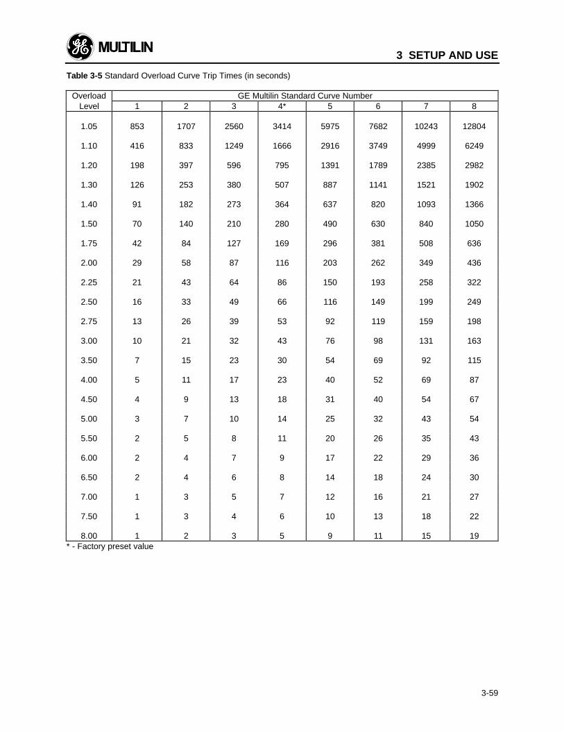
3 SETUP AND USE
3-59
Table 3-5 Standard Overload Curve Trip Times (in seconds)
Overload GE Multilin Standard Curve NumberLevel 1 2 3 4* 5 6 7 8
1.05 853 1707 2560 3414 5975 7682 10243 12804
1.10 416 833 1249 1666 2916 3749 4999 6249
1.20 198 397 596 795 1391 1789 2385 2982
1.30 126 253 380 507 887 1141 1521 1902
1.40 91 182 273 364 637 820 1093 1366
1.50 70 140 210 280 490 630 840 1050
1.75 42 84 127 169 296 381 508 636
2.00 29 58 87 116 203 262 349 436
2.25 21 43 64 86 150 193 258 322
2.50 16 33 49 66 116 149 199 249
2.75 13 26 39 53 92 119 159 198
3.00 10 21 32 43 76 98 131 163
3.50 7 15 23 30 54 69 92 115
4.00 5 11 17 23 40 52 69 87
4.50 4 9 13 18 31 40 54 67
5.00 3 7 10 14 25 32 43 54
5.50 2 5 8 11 20 26 35 43
6.00 2 4 7 9 17 22 29 36
6.50 2 4 6 8 14 18 24 30
7.00 1 3 5 7 12 16 21 27
7.50 1 3 4 6 10 13 18 22
8.00 1 2 3 5 9 11 15 19* - Factory preset value
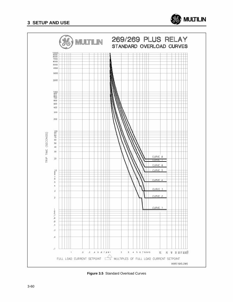
3 SETUP AND USE
3-60
Figure 3.5 Standard Overload Curves
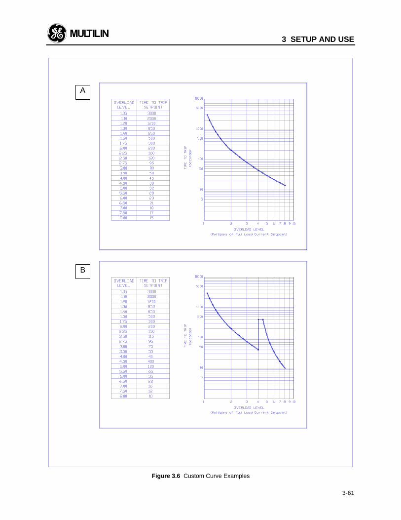
3 SETUP AND USE
3-61
Figure 3.6 Custom Curve Examples
A
B
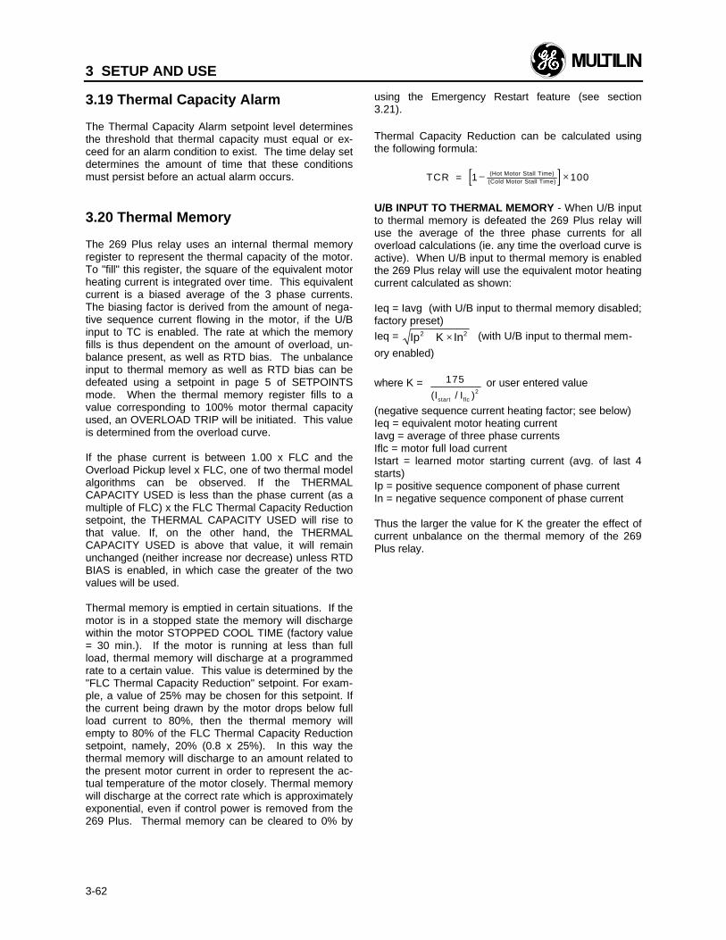
3 SETUP AND USE
3-62
3.19 Thermal Capacity Alarm
The Thermal Capacity Alarm setpoint level determinesthe threshold that thermal capacity must equal or ex-ceed for an alarm condition to exist. The time delay setdetermines the amount of time that these conditionsmust persist before an actual alarm occurs.
3.20 Thermal Memory
The 269 Plus relay uses an internal thermal memoryregister to represent the thermal capacity of the motor.To "fill" this register, the square of the equivalent motorheating current is integrated over time. This equivalentcurrent is a biased average of the 3 phase currents.The biasing factor is derived from the amount of nega-tive sequence current flowing in the motor, if the U/Binput to TC is enabled. The rate at which the memoryfills is thus dependent on the amount of overload, un-balance present, as well as RTD bias. The unbalanceinput to thermal memory as well as RTD bias can bedefeated using a setpoint in page 5 of SETPOINTSmode. When the thermal memory register fills to avalue corresponding to 100% motor thermal capacityused, an OVERLOAD TRIP will be initiated. This valueis determined from the overload curve.
If the phase current is between 1.00 x FLC and theOverload Pickup level x FLC, one of two thermal modelalgorithms can be observed. If the THERMALCAPACITY USED is less than the phase current (as amultiple of FLC) x the FLC Thermal Capacity Reductionsetpoint, the THERMAL CAPACITY USED will rise tothat value. If, on the other hand, the THERMALCAPACITY USED is above that value, it will remainunchanged (neither increase nor decrease) unless RTDBIAS is enabled, in which case the greater of the twovalues will be used.
Thermal memory is emptied in certain situations. If themotor is in a stopped state the memory will dischargewithin the motor STOPPED COOL TIME (factory value= 30 min.). If the motor is running at less than fullload, thermal memory will discharge at a programmedrate to a certain value. This value is determined by the"FLC Thermal Capacity Reduction" setpoint. For exam-ple, a value of 25% may be chosen for this setpoint. Ifthe current being drawn by the motor drops below fullload current to 80%, then the thermal memory willempty to 80% of the FLC Thermal Capacity Reductionsetpoint, namely, 20% (0.8 x 25%). In this way thethermal memory will discharge to an amount related tothe present motor current in order to represent the ac-tual temperature of the motor closely. Thermal memorywill discharge at the correct rate which is approximatelyexponential, even if control power is removed from the269 Plus. Thermal memory can be cleared to 0% by
using the Emergency Restart feature (see section3.21).
Thermal Capacity Reduction can be calculated usingthe following formula:
[ ]TCR = 1 Hot Motor Stall Time)(Cold Motor Stall Time)− ×( 100
U/B INPUT TO THERMAL MEMORY - When U/B inputto thermal memory is defeated the 269 Plus relay willuse the average of the three phase currents for alloverload calculations (ie. any time the overload curve isactive). When U/B input to thermal memory is enabledthe 269 Plus relay will use the equivalent motor heatingcurrent calculated as shown:
Ieq = Iavg (with U/B input to thermal memory disabled;factory preset)Ieq = Ip K In2 2+ × (with U/B input to thermal mem-
ory enabled)
where K = 1752(Istart / )Iflc
or user entered value
(negative sequence current heating factor; see below)Ieq = equivalent motor heating currentIavg = average of three phase currentsIflc = motor full load currentIstart = learned motor starting current (avg. of last 4starts)Ip = positive sequence component of phase currentIn = negative sequence component of phase current
Thus the larger the value for K the greater the effect ofcurrent unbalance on the thermal memory of the 269Plus relay.
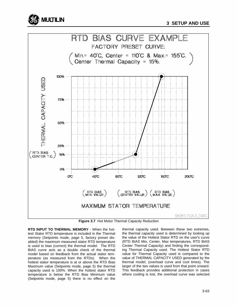
3 SETUP AND USE
3-63
Figure 3.7 Hot Motor Thermal Capacity Reduction
RTD INPUT TO THERMAL MEMORY - When the hot-test Stator RTD temperature is included in the Thermalmemory (Setpoints mode, page 5, factory preset dis-abled) the maximum measured stator RTD temperatureis used to bias (correct) the thermal model. The RTDBIAS curve acts as a double check of the thermalmodel based on feedback from the actual stator tem-perature (as measured from the RTDs). When thehottest stator temperature is at or above the RTD BiasMaximum value (Setpoints mode, page 5) the thermalcapacity used is 100%. When the hottest stator RTDtemperature is below the RTD Bias Minimum value(Setpoints mode, page 5) there is no effect on the
thermal capacity used. Between these two extremes,the thermal capacity used is determined by looking upthe value of the Hottest Stator RTD on the user's curve(RTD BIAS Min, Center, Max temperatures, RTD BIASCenter Thermal Capacity) and finding the correspond-ing Thermal Capacity used. The Hottest Stator RTDvalue for Thermal Capacity used is compared to thevalue of THERMAL CAPACITY USED generated by thethermal model, (overload curve and cool times). Thelarger of the two values is used from that point onward.This feedback provides additional protection in caseswhere cooling is lost, the overload curve was selected
3 SETUP AND USE
3-64
incorrectly, the ambient temperature is unusually high,etc.
The two-part curve allows for easy fitting of HOT /COLD curves to the RTD BIAS feature. The minimumvalue could be set to the ambient temperature the mo-tor was designed to (40°C). The center point for ther-mal capacity could be set to the difference between thehot and cold curves (eg. 15 %). The center point tem-perature could be set for hot running temperature (eg.110°C). Finally, the Maximum value could be set to therating of the insulation (eg. 155°C) The user has theflexibility to set the RTD BIAS as liberally or conserva-tively as he/she desires.
It should be noted that the Thermal Capacity values forthe RTD BIAS curve MUST increase with temperature.For this reason, there is range checking on the tem-perature setpoints (eg. the minimum setpoint cannot belarger than the center temperature setpoint). It maytake a couple of attempts to set the parameters to thedesired values (it is best to start with the minimum ormaximum value).
It should also be noted that RTD BIAS may force theTHERMAL CAPACITY USED value to 100%, but it willnever alone cause a trip. If the RTD BIAS does forceTHERMAL CAPACITY USED to 100%, when the motorload increases above the overload pickup value, a tripwill occur immediately (see Appendix B). A trip byRTDs will only occur when the RTD values exceed theuser's trip level for RTD trip, as defined in page 2 ofsetpoints.
Additionally, RTD bias may artificially sustain lockouttimes for the O/L and Start Inhibit features as they arebased on thermal capacity.
LEARNED COOLING TIMES - Through various meas-urement and averaging techniques the 269 Plus relay"learns" a number of motor parameters. All learnedvalues can be examined in page 6 of ACTUAL VALUESmode. If RTDs are used to monitor the temperature ofthe motor stator the relay will learn the running andstopped cooling times of the motor. In this way the 269Plus provides increased accuracy in the thermal mod-eling of the protected motor. When RTD #10 is usedfor ambient air temperature monitoring even greaterthermal protection is provided since the cooling airtemperature is known. In this case the learned cooltimes are based on the difference between the ambienttemperature and the average stator RTD temperature.When no ambient sensing is used the learned cooltimes are based only on the average stator RTD tem-perature. If no stator RTDs are used, or if the DEFEATLEARNED COOL TIME setpoint (SETPOINTS mode,page 5) is left as "YES", the relay will use the defaultstopped and running cool time setpoints.
NOTE: The learned cooling times should not be en-abled until the 269 Plus relay has had sufficient time to
learn the actual motor cooling times. The time requiredwill vary between motors, however several start/stopcycles will be necessary.
The 269 Plus relay learns the motor cooling times overvarious temperature ranges. Thus the times shown inpage 6 of ACTUAL VALUES mode (LEARNEDRUNNING COOL TIME, LEARNED STOPPED COOLTIME) will reflect the total cooling time as a combina-tion of the cooling times over each temperature range.
START INHIBIT - An OVERLOAD TRIP caused by theexhaustion of motor thermal capacity will cause a lock-out. A relay reset will not be allowed until the memoryhas discharged to 15% thermal capacity used. At thispoint the relay can be reset.
If the Start Inhibit feature is enabled (SETPOINTS,page 5) a motor start will not be allowed until the ther-mal memory has discharged sufficiently to make thestart possible. The 269 Plus relay uses the "LEARNEDStart Capacity required" (ACTUAL VALUES, page 6) todetermine if a start is possible. If sufficient thermalcapacity is available for a start, the start will be suc-cessful. Thus the START INHIBIT lock-out time is ad-justed to allow for optimum motor usage. To override aSTART INHIBIT or OVERLOAD TRIP lock-out conditionthe Emergency Restart feature can be used. If theStart Inhibit feature is disabled the OVERLOAD TRIPlock-out time will not be adjusted by the learned start-ing capacity value and will represent the time for thethermal memory to discharge to 15% thermal capacityused. Thus the lockout time will equal 85% of theSTOPPED COOL TIME when Start Inhibit is disabled.When Start Inhibit is enabled the OVERLOAD TRIPlock-out time will represent the time for the thermalmemory to discharge to the "LEARNED Start Capacityrequired" value.
Before the 269 Plus relay has learned the actual StartCapacity required by the motor, this value will default to40%.
The “Learned start capacity required” is the amount ofthermal capacity used and learned by the relay over thelast five starts. To ensure successful completion of thelongest and most demanding starts, a safe marginbetween the actual start capacity required and thelearned value is built-in. This safety margin can be ashigh as 24%.
Every start is examined and its thermal capacity iscaptured and shown on page 5 of Actual Values as the“Learned start capacity, last start TC”. If the valuelearned is less than 10%, it is forced to 10% when it isused in calculating the “Learned start capacity required”over the last 5 starts. It is forced to a maximum of 70%if the TC learned for the last start is more than 70%. Itis recommended that the “Start inhibit” feature shouldnot be enabled until the 269 Plus has had sufficienttime to learn the actual motor start thermal capacityunder normal operating conditions. The time required
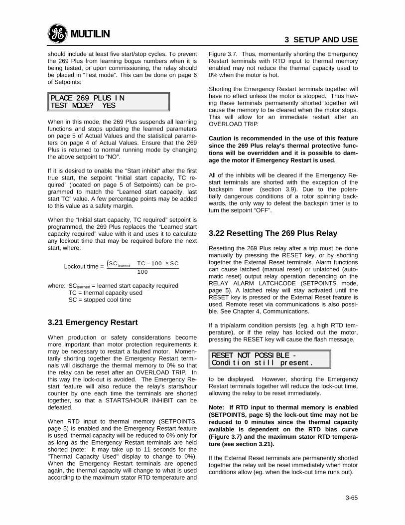
3 SETUP AND USE
3-65
should include at least five start/stop cycles. To preventthe 269 Plus from learning bogus numbers when it isbeing tested, or upon commissioning, the relay shouldbe placed in “Test mode”. This can be done on page 6of Setpoints:
PLACE 269 PLUS INPLACE 269 PLUS INTEST MODE? YESTEST MODE? YES
When in this mode, the 269 Plus suspends all learningfunctions and stops updating the learned parameterson page 5 of Actual Values and the statistical parame-ters on page 4 of Actual Values. Ensure that the 269Plus is returned to normal running mode by changingthe above setpoint to “NO”.
If it is desired to enable the “Start inhibit” after the firsttrue start, the setpoint “Initial start capacity, TC re-quired” (located on page 5 of Setpoints) can be pro-grammed to match the “Learned start capacity, laststart TC” value. A few percentage points may be addedto this value as a safety margin.
When the “Initial start capacity, TC required” setpoint isprogrammed, the 269 Plus replaces the “Learned startcapacity required” value with it and uses it to calculateany lockout time that may be required before the nextstart, where:
Lockout time = ( )SC learned + − ×TC SC100
100
where: SClearned = learned start capacity requiredTC = thermal capacity usedSC = stopped cool time
3.21 Emergency Restart
When production or safety considerations becomemore important than motor protection requirements itmay be necessary to restart a faulted motor. Momen-tarily shorting together the Emergency Restart termi-nals will discharge the thermal memory to 0% so thatthe relay can be reset after an OVERLOAD TRIP. Inthis way the lock-out is avoided. The Emergency Re-start feature will also reduce the relay's starts/hourcounter by one each time the terminals are shortedtogether, so that a STARTS/HOUR INHIBIT can bedefeated.
When RTD input to thermal memory (SETPOINTS,page 5) is enabled and the Emergency Restart featureis used, thermal capacity will be reduced to 0% only foras long as the Emergency Restart terminals are heldshorted (note: it may take up to 11 seconds for the"Thermal Capacity Used" display to change to 0%).When the Emergency Restart terminals are openedagain, the thermal capacity will change to what is usedaccording to the maximum stator RTD temperature and
Figure 3.7. Thus, momentarily shorting the EmergencyRestart terminals with RTD input to thermal memoryenabled may not reduce the thermal capacity used to0% when the motor is hot.
Shorting the Emergency Restart terminals together willhave no effect unless the motor is stopped. Thus hav-ing these terminals permanently shorted together willcause the memory to be cleared when the motor stops.This will allow for an immediate restart after anOVERLOAD TRIP.
Caution is recommended in the use of this featuresince the 269 Plus relay's thermal protective func-tions will be overridden and it is possible to dam-age the motor if Emergency Restart is used.
All of the inhibits will be cleared if the Emergency Re-start terminals are shorted with the exception of thebackspin timer (section 3.9). Due to the poten-tially dangerous conditions of a rotor spinning back-wards, the only way to defeat the backspin timer is toturn the setpoint “OFF”.
3.22 Resetting The 269 Plus Relay
Resetting the 269 Plus relay after a trip must be donemanually by pressing the RESET key, or by shortingtogether the External Reset terminals. Alarm functionscan cause latched (manual reset) or unlatched (auto-matic reset) output relay operation depending on theRELAY ALARM LATCHCODE (SETPOINTS mode,page 5). A latched relay will stay activated until theRESET key is pressed or the External Reset feature isused. Remote reset via communications is also possi-ble. See Chapter 4, Communications.
If a trip/alarm condition persists (eg. a high RTD tem-perature), or if the relay has locked out the motor,pressing the RESET key will cause the flash message,
RESET NOT POSSIBLE -RESET NOT POSSIBLE -Condition still present.Condition still present.
to be displayed. However, shorting the EmergencyRestart terminals together will reduce the lock-out time,allowing the relay to be reset immediately.
Note: If RTD input to thermal memory is enabled(SETPOINTS, page 5) the lock-out time may not bereduced to 0 minutes since the thermal capacityavailable is dependent on the RTD bias curve(Figure 3.7) and the maximum stator RTD tempera-ture (see section 3.21).
If the External Reset terminals are permanently shortedtogether the relay will be reset immediately when motorconditions allow (eg. when the lock-out time runs out).
3 SETUP AND USE
3-66
The 269 Plus relay cannot be reset after a DifferentialInput Trip or Spare Input Trip until the contacts con-nected across the Differential Input or Spare Input ter-minals have been opened.
SINGLE SHOT RESTART - The 269 Plus relay has aselectable single-shot restart feature which will allowthe motor to be restarted immediately after an overloadtrip. To allow the motor to be restarted the relay de-creases its internal value for motor thermal capacityused. However if two overload trips occur within a lock-out time delay, the 269 Plus will not allow an immediaterestart. The displayed lock-out time must be allowed torun out before the motor can be restarted. This featurecan be selected in page 5 of SETPOINTS mode and isfactory preset as disabled.
SPECIAL EXTERNAL RESET - The 269 Plus relayalso has a special external reset feature which can beselected in page 5 of SETPOINTS mode. When thisfeature is enabled, shorting the External Reset termi-nals together will cause all output relays to be reset,while pressing the keypad reset key will cause all relaysexcept AUX. 1 to be reset. This feature is factory pre-set as disabled.
Note: This feature works for 269 Plus relay tripfunctions only. Trip functions assigned to the TRIP& AUX. 1 output relays cannot be reset using thereset key.
If the 269 Plus relay trips and then loses control power,the trip function will become active again once controlpower is re-applied. For example, if a GROUNDFAULT TRIP occurs and then control power for the re-lay is removed and later returned, the message"GROUND FAULT TRIP" will appear on the display andthe output relay assigned to the Ground Fault Tripfunction will become active.
Note: If control power is removed for more thanone hour after a trip the 269 Plus relay may be resetwhen power is re-applied (for O/L trips).
3.23 269 Plus Relay Self-Test
The 269 Plus relay's internal circuitry self-test consistsof three separate tests. A/D, RTD, and memory cir-cuitry tests are continually performed. The A/D testinvolves sending a known, precise voltage level throughthe A/D circuitry and seeing if it is converted correctly.The RTD test involves reading a known, internal resis-tance and checking to see if the correct temperature isdetermined. To test the memory circuitry, test data isstored in the 269 Plus relay's non-volatile RAM and isthen read and compared with the original data.
Should any of these tests indicate an internal circuitryfailure, the "SERVICE" LED will start to flash and the
output relay programmed for the self-test feature willactivate.
Note: When a relay A/D or memory self-test failureoccurs, all metering and protective functions willbe suspended. The ACTUAL VALUES display for allparameters will be zero in order to avoid nuisancetripping. When in this state, the relay will not pro-vide motor protection. If a memory failure occurs,the factory setpoints will be reloaded into the 269Plus. If an RTD hardware failure occurs the "# OFSTATOR RTDS USED" setpoint will be automaticallyset to 0 and the RTD ALARM and TRIP levels will beautomatically set to OFF; however all current-related functions will continue to operate normally.
3.24 Statistical Data Features
The model 269 Plus relay offers a record of maximumRTD temperatures and pre-trip current and RTD valuesin addition to a full range of motor statistical data. Themaximum RTD temperature data is found on page 2 ofACTUAL VALUES mode and can be cleared to zero bystoring a YES in response to the "CLEAR LASTACCESS DATA?" question at the end of page 2. Pre-trip motor current and temperature values are found inACTUAL VALUES mode, page 5. These values will beupdated only when a relay trip occurs. Note that if a tripfunction setpoint is set to INST. (instantaneous) andthis type of trip occurs, the values for pre-trip currentwill not be recorded exactly. This is because the relayhas tripped instantaneously and thus did not haveenough time to update the registers holding this infor-mation. The pre-trip values can be cleared to zero bystoring a “YES” in response to the “CLEAR PRE-TRIPDATA?” question at the end of page 5 of Actual Values.
On the model 269 Plus statistical data is found on page4 of ACTUAL VALUES mode. All of this data can becleared to zero by storing a value of YES in response tothe "START NEW COMMISSIONING?" question at theend of page 4.
All of the statistics in this page will reset to zero afterreaching 255. The running hours and megawatthoursdata will reset to zero after each reaching the number65535.
If a 269 Plus relay is to be taken out of service formaintenance or testing purposes, the statistical dataaccumulated by the relay may be copied to the newrelay replacing it. Simply record the information frompage 4 of Actual Values and call the factory for a de-tailed procedure on transferring this information to thenew relay.
The obvious benefit of this exercise is the ability of thenew relay to start with accurate data about the motorand the system to maintain a continuity from relay to
3 SETUP AND USE
3-67
relay during maintenance or testing of the original 269Plus.
When the original relay is ready to be reinstalled, thesame procedure may be followed to transfer the accu-mulated statistical data from the replacement relay tothe original 269 Plus.
3.25 Factory Setpoints
When the 269 Plus relay is shipped, it will have defaultsetpoints stored in its non-volatile memory. These val-ues are meant to be used as a starting point for pro-gramming the relay and should be changed as eachapplication requires.
In the event of a non-volatile memory failure, which willbe detected by the self-test feature (see section 3.23),the 269 Plus relay will reload the factory setpoints butwill not provide motor protection.
A list of the motor current, RTD, and overload curvesetpoints is given in Table 3-6. For other factory set-points see Tables 3-7 and 3-3.
3.26 Meter Option
The addition of a GE Multilin MPM meter to a 269 Plusprovides valuable voltage and power measurement.These values are good for troubleshooting and protec-tive features.
In order to install the MPM, all connections to the metermust be made. Then, on the 269 Plus page 7 of Set-points, meter CT primary, VT ratio, and VT secondarymust be programmed. These setpoints will be sent tothe meter via the comm. link for meter calculations.** IMPORTANT ** Only after the above steps are com-plete may the MPM be brought on-line by changing themeter on-line setpoint (page 7) to YES. The 269 Pluswill then initiate communication with the meter andactual values from the meter may be displayed.
A value for MegaWattHours from 0-65535 may be dis-played in the Statistical data of Actual Values page 4.Voltage, kWatts, KVARS, Power Factor, and Frequencymay be viewed on page 7 of Actual Values. These val-ues may also be seen as their pre-trip levels on page 5of Actual Values.
The Undervoltage trip and alarm levels determine thethreshold that voltage must fall below for an alarm ortrip condition to exist. The time delay set determinesthe amount of time that these conditions must persistbefore an actual trip or alarm occurs.
The Power Factor Lag and Power Factor Lead trip andalarm levels determine the threshold that the powerfactor must fall below for an alarm or trip condition to
exist. The time delay set determines the amount of timethat these conditions must persist before an actual tripor alarm occurs.
Power Factor is commonly used for synchronous motorprotection. Ideally, synchronous motors run at unitypower factor. Conditions may exist where the powerfactor drops below an acceptable level. This may becaused by several factors, such as the loss of field tothe main exciter, accidental tripping of the field breaker,short circuits in the field currents, poor brush contact inthe exciter, or loss of AC supply to the excitation sys-tem.
Power Factor Lead and Power Factor Lag alarm andtrip setpoints with programmable time delays can beused to detect such conditions as out of step, loss ofsynchronism, or loss of field.
Where the motor is started unloaded and the field ap-plied later in the start, the power factor may be pooruntil the motor is loaded and synchronous speed isattained. It may then be necessary to block power fac-tor protection until the motor is up to speed.
A setpoint on page 7 allows the user to pick one of twomethods of blocking power factor protection on start.Answering “NO” to the setpoint “BLOCK PFPROTECTION ON START?” puts the 269 Plus in amode where the “Power Factor protection delay” fea-ture may be enabled. So, when programmed, after themotor has successfully completed a start, this setpointrequired that the measured power factor comes be-tween the user specified POWER FACTOR TRIP LEADand LAG setpoints for the specified period of time(user’s value for Power Factor protection delay) beforethe power factor trip and alarm features become active.A stop condition resets the algorithm.
Answering “YES” to the setpoint “BLOCK PFPROTECTION ON START?” puts the 269 Plus in an-other mode where “Block PF alarm & trip on start by:XXX seconds” may be enabled. When this delay isprogrammed, the 269 Plus blocks power factor lag andpower factor lead alarm and trip protection from startuntil the time expires. When programming this delay,consideration must be given to the time it takes themotor to start, apply the field and the load.
The positive kvar alarm and negative kvar alarm set-point levels determine the threshold that kvars mustexceed for an alarm or trip condition to exist. The timedelay set determines the amount of time that theseconditions must persist before an actual trip or alarmoccurs.
All motors (synchronous and induction) require varsfrom the system to run. The 269 Plus displays con-sumed vars by the motor as positive vars. Conversely,if a synchronous motor is run overexcited as a syn-chronous condensor, it may be capable of supplyingvars back to the system. Such motors are typically
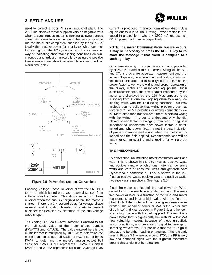
3 SETUP AND USE
3-68
used to correct a poor PF in an industrial plant. The269 Plus displays motor supplied vars as negative varswhen a synchronous motor is running at synchronousspeed, its power factor is unity and the vars required torun the motor are completely supplied by the field. So,ideally the reactive power for a unity synchronous mo-tor coming from the AC system is zero. Hence, anotherway of indicating abnormal running conditions on syn-chronous and induction motors is by using the positivekvar alarm and negative kvar alarm levels and the kvaralarm time delay.
Figure 3.8 Power Measurement Conventions
Enabling Voltage Phase Reversal allows the 269 Plusto trip or inhibit based on phase reversal sensed fromvoltage from the meter. This allows sensing of phasereversal when the bus is energized before the motor isstarted. There is a 3-4 second delay for voltage phasereversal, and it is also defeated on starts to preventnuisance trips caused by distortion of the bus voltagewave shape.
The Analog Out Scale Factor setpoint is entered to setthe Full Scale value for the meter analog outputs(KWATTS and KVARS). The value entered here is themultiplier that is multiplied by 100 KW to determine themeter’s analog output Full Scale for KWATTS, or by 30KVAR to determine the meter’s analog output FullScale for KVAR. 4 mA represents 0 KWATTS and 0KVARS and 20 mA represents full scale. Average RMS
current is produced in analog form where 4-20 mA isequivalent to 0 A to 1×CT rating. Power factor is pro-duced in analog form where 4/12/20 mA represents -0/1/+0 power factor value respectively.
NOTE: If a meter Communications Failure occurs,it may be necessary to press the RESET key to re-move the message if that alarm is assigned to alatching relay.
On commissioning of a synchronous motor protectedby a 269 Plus and a meter, correct wiring of the VTsand CTs is crucial for accurate measurement and pro-tection. Typically, commissioning and testing starts withthe motor unloaded. It is also typical to examine thepower factor to verify the wiring and proper operation ofthe relays, motor and associated equipment. Undersuch circumstances, the power factor measured by themeter and displayed by the 269 Plus appears to beswinging from a very low lagging value to a very lowleading value with the field being constant. This maymislead you to believe that wiring problems such asreversed CT or VT polarities or wrong connections ex-ist. More often than not however, there is nothing wrongwith the wiring. In order to understand why the dis-played power factor is swinging from lead to lag, it isimportant to understand how power factor is deter-mined and why power factor is not the best indicationof proper operation and wiring when the motor is un-loaded and the field applied. Recommendations will bemade for commissioning and checking for wiring prob-lems.
THE PHENOMENON
By convention, an induction motor consumes watts andvars. This is shown in the 269 Plus as positive wattsand positive vars. A synchronous motor can consumewatts and vars or consume watts and generate vars(synchronous condensors). This is shown in the 269Plus as positive watts, positive vars and positive watts,negative vars respectively. See Figure 3.8.
Since the motor is unloaded, the real power or kW re-quired to run the machine is at its minimum. The reac-tive power or kvar is a function of the field and motorrequirement, and is at a high value with the field ap-plied. In fact the motor will be running extremely over-excited. The apparent power or kVA is the vector sumof both kW and kvar as seen in Figure 3.9, and hence itis at a high value with the field applied. The result is apower factor that is significantly low with PF = kW/kVA(low value/high value). Because of these unrealisticmotor conditions, and because of digital technology ofsampling waveforms, it is possible that the PF sign isdetected to be either leading or lagging. This is clearlyseen in Figure 3.8 where at around 270°, the PF is verylow and changes signs with the slightest movementaround this angle in either direction.
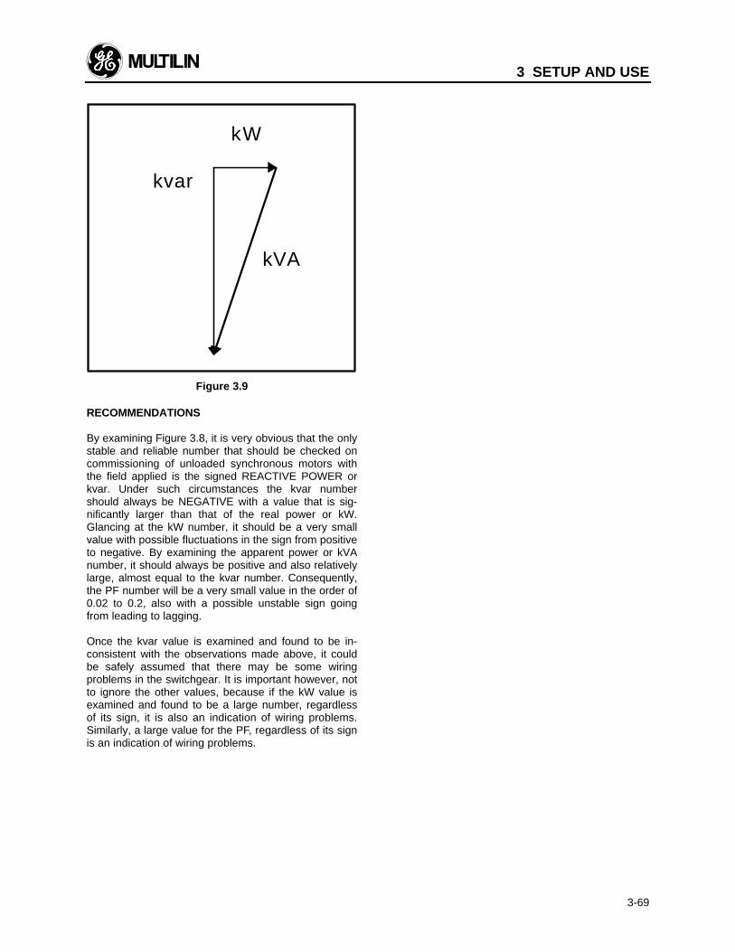
3 SETUP AND USE
3-69
Figure 3.9
RECOMMENDATIONS
By examining Figure 3.8, it is very obvious that the onlystable and reliable number that should be checked oncommissioning of unloaded synchronous motors withthe field applied is the signed REACTIVE POWER orkvar. Under such circumstances the kvar numbershould always be NEGATIVE with a value that is sig-nificantly larger than that of the real power or kW.Glancing at the kW number, it should be a very smallvalue with possible fluctuations in the sign from positiveto negative. By examining the apparent power or kVAnumber, it should always be positive and also relativelylarge, almost equal to the kvar number. Consequently,the PF number will be a very small value in the order of0.02 to 0.2, also with a possible unstable sign goingfrom leading to lagging.
Once the kvar value is examined and found to be in-consistent with the observations made above, it couldbe safely assumed that there may be some wiringproblems in the switchgear. It is important however, notto ignore the other values, because if the kW value isexamined and found to be a large number, regardlessof its sign, it is also an indication of wiring problems.Similarly, a large value for the PF, regardless of its signis an indication of wiring problems.
kvar
kW
kVA
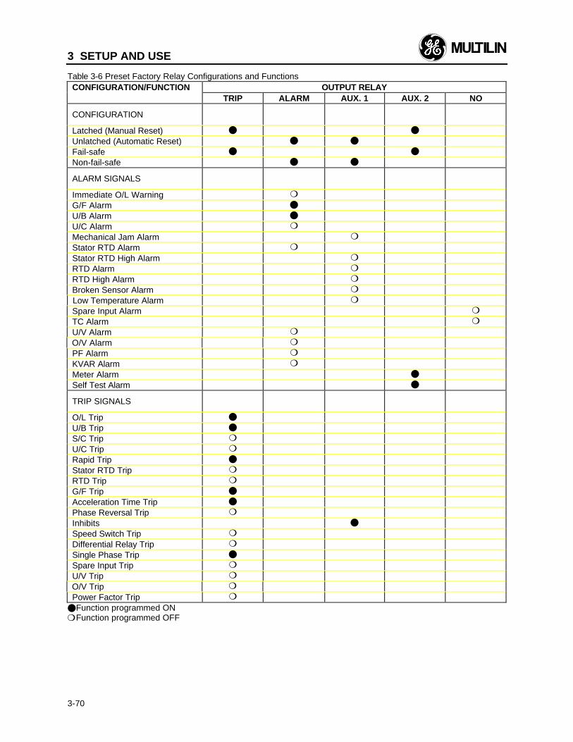
3 SETUP AND USE
3-70
Table 3-6 Preset Factory Relay Configurations and FunctionsCONFIGURATION/FUNCTION OUTPUT RELAY
TRIP ALARM AUX. 1 AUX. 2 NO
CONFIGURATION
Latched (Manual Reset) l l
Unlatched (Automatic Reset) l l
Fail-safe l l
Non-fail-safe l l
ALARM SIGNALS
Immediate O/L Warning m
G/F Alarm l
U/B Alarm l
U/C Alarm m
Mechanical Jam Alarm m
Stator RTD Alarm m
Stator RTD High Alarm m
RTD Alarm m
RTD High Alarm m
Broken Sensor Alarm m
Low Temperature Alarm m
Spare Input Alarm m
TC Alarm m
U/V Alarm m
O/V Alarm m
PF Alarm m
KVAR Alarm m
Meter Alarm l
Self Test Alarm l
TRIP SIGNALS
O/L Trip l
U/B Trip l
S/C Trip m
U/C Trip m
Rapid Trip l
Stator RTD Trip m
RTD Trip m
G/F Trip l
Acceleration Time Trip l
Phase Reversal Trip m
Inhibits l
Speed Switch Trip m
Differential Relay Trip m
Single Phase Trip l
Spare Input Trip m
U/V Trip m
O/V Trip m
Power Factor Trip m
lFunction programmed ONmFunction programmed OFF
4 COMMUNICATIONS
4-1
The 269 Plus Motor Protection relays communicatewith other computerized equipment such as program-mable controllers, personal computers or plant mastercomputers with the Modicon Standard Data Communi-cation Network (MODBUS RTU).
This document describes the subset of protocol assupported by the 269 Plus Motor Protection relays.
4.1 Modes of Operation
• GE Multilin 269 Plus relays always act asMODBUS slaves, meaning they never initiate adialogue but listen and respond to the bus mastercomputer.
• Only the Remote Terminal Unit (RTU) format of theMODBUS protocol is adopted for the 269 Plus.The format is described later and features binarydata format rather than ASCII character communi-cations.
• As the physical layer of the protocol, two-wire (4-wire is also available as a modification for a mod-erate cost) Multi-drop RS485 standard is sup-ported. This standard uses twisted pair cable. Upto 32 269 Plus relays on up to 4000 ft of cable canbe supported.
• Optionally, Serial Communication Interface (SCI)boxes can be purchased to support RS232 stan-dard for the connection of a group of relays on anRS485 bus to RS232 which is supported by PCsand some PLCs.
• Since the operation of 269 Plus relays are registerbased, a master computer can monitor and controlthe operation of the relays by reading or writing tothe relay registers. Therefore, the Register Readand Write functions of the MODBUS are supportedonly. These are described later.
• 269 Plus relays provide flexibility towards mastercomputer corrective actions upon communicationerrors and timeouts. This is left to the discretion ofthe master programmer.
The protocol, as supported by 269 Plus relays, featuresthe following:
4.2 Physical Layer
The electrical interface is a two-wire bidirectional multi-drop RS485 on a shielded twisted pair cable. A Belden9841 insulated 24 Gage shielded twisted pair cableshould be used. The connection to the 269 Plus is by 2terminals on a terminal block on the 269 Plus markedas:
47 46+ –
Where + is the positive wire, and – the negative wire.The shield must be connected at terminal 88 on each269 Plus throughout the link and GROUNDED AT THEMASTER ONLY. If a GE Multilin SCI box (RS232/RS485 converter) is used, no grounding of the shield isnecessary. See Fig. 4.1. The cable should be termi-nated, at the two extreme ends, by resistors equal invalue to its characteristic impedance (120Ω for the Bel-den 9841 AWG twisted pair.) in series with 1nF/50Vcapacitors. See Figure 4.1. A terminator assembly withthe resistor/capacitor network may be obtained fromGE Multilin.
The communication to the 269 Plus is half-duplex.This means a 269 Plus listens to receive a command,services it, then transmits the reply. The 269 Plus willnot service and process a new request until the currentrequest is processed.
The message bytes are communicated as asynchro-nous items with 1 start bit, 8 data bits and one stop bit.This produces a 10 bit data frame. (Some modems donot support 11 bit data frames at baud rates of greaterthan 300bps). The rates at which data can be commu-nicated are 300, 1200 or 2400bps. The unit defaults to2400 baud. If 300 or 1200 baud is desired, contact thefactory.
Each relay on the network is identified by a one byteADDRESS which is locally programmed to the 269non-volatile memory (NOVRAM). This is a setpointlocated on page 5 of Setpoints.
4.3 Packet Format
The communications take place in packets which aregroups of asynchronous bytes that are framed by silenttime gaps. The packet format of RTU version ofMODBUS is adopted by GE Multilin 269 Plus relays.This format is as follows:
SILENTTIME ADDRESS FUNCTION
DATABYTES CRC
SILENTTIME
1 byte 1 byte N bytes 2 bytes
Where:- silent times are used as packet frames and separa-
tors. They are equivalent to 3.5 bytes transmissionsilent time (29.2ms for 1200 baud). The receivingdevice, upon detecting this silent time, readies itselfto recognize the next received byte as theADDRESS.
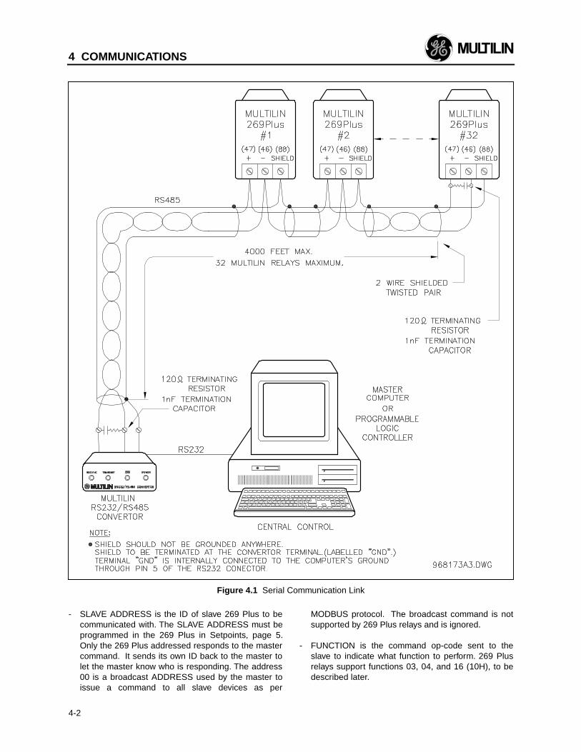
4 COMMUNICATIONS
4-2
Figure 4.1 Serial Communication Link
- SLAVE ADDRESS is the ID of slave 269 Plus to becommunicated with. The SLAVE ADDRESS must beprogrammed in the 269 Plus in Setpoints, page 5.Only the 269 Plus addressed responds to the mastercommand. It sends its own ID back to the master tolet the master know who is responding. The address00 is a broadcast ADDRESS used by the master toissue a command to all slave devices as per
MODBUS protocol. The broadcast command is notsupported by 269 Plus relays and is ignored.
- FUNCTION is the command op-code sent to theslave to indicate what function to perform. 269 Plusrelays support functions 03, 04, and 16 (10H), to bedescribed later.
4 COMMUNICATIONS
4-3
- DATA BYTES are the information needed to performthe requested function. This field may contain val-ues, address references, byte counts and limits.
- CRC is the error check code. It is a 16-bit CyclicRedundancy Check (CRC) computed by the senderand appended to the packet. The code is recom-puted by the receiver and compared to the receivedcode. If different, an error in transmission has oc-curred.
4.4 The Handshake
The Master always initiates the dialogue by sending acommand. It also starts a response timer to see thatthe slave is replying in time. This timer is a function oftransmission time of the command, reply packets, plusthe time required by the 269 Plus to collect informationfrom its registers. It is determined mutually by themaster programmer and GE Multilin depending on thenumber of register data to be processed in one com-mand. The following is a table of results recorded fromthe 269 Plus at 2400 baud:
BYTESREAD
MIN.RESPONSETIME (ms)
AVG.RESPONSETIME (ms)
MAX.RESPONSETIME (ms)
2 66 75 11710 78 82 123250 206 222 242
If the reply from the slave arrives within this time, and itis error free, the master considers the dialogue suc-cessful and accepts the confirmation reply and anyreceived data. Otherwise, if the reply is not in time or ifit contains an error or exception reply, the master takesa corrective action at the discretion of the master pro-grammer.
Such a corrective action could include repeating thecommand for this slave for a predetermined number oftimes, continuing the scan with the next slave, or post-ing a note on the old un-updated data and then con-tinuing the scan. 269 Plus relays are quite flexible inthis regard; they simply reply if they are commandedregardless of it being an original query or a repetition.
Every time the master attempts a new dialogue to anew slave or repeats the command to the same slave,it should observe a 3.5 character silent time. Theslaves detect the silent time and reset themselves for anew dialogue.
If a slave detects a communication error in the mastercommand (CRC), it does not provide a reply back.This way the master times out and repeats the com-mand, if it is so programmed. However, if the mastercommand contains functional errors such as wrongfunction op-code, wrong register address or out ofrange data is detected, it provides an error code to the
master to invoke corrective action. The error mes-sages and exception replies are discussed later in thedocument.
4.5 Supported Functions
The following functions are supported:
03 Read Relay Setpoint Registers.04 Read Relay Actual Values.16 (10h) Write Relay Setpoints.
These functions are described in detail as follows:
FUNCTION 03h, READ SETPOINTS (Holding Regis-ters)
MODBUS "Read Holding Registers" is interpreted hereas "Read 269 Plus Setpoints". It is used by the MasterComputer to program the relaying parameters. Up to125 consecutive registers (250 bytes) can be read withone command. Broadcast command is not allowed withthis function.
The 269 Plus Motor Protection Setpoint Register mapis given in Table 4-1. This table represents the registersas inserted in the packet to be communicated. Theyare 16-bit words. The format of the packets communi-cated is given, with an example as follows:
The Master computer, in order to read the 3 consecu-tive setpoint registers starting from register address006Bh from slave number 11H, sends the command:
HI LO HI LO LO HI11h 03h 00h 6Bh 00h 03h 76h 87h
ADDRESS FUNCTION START REG COUNT CRC
slave number 11h replies with:
HI LO HI LO HI LO LO HI11h 03h 06h 02h 2Bh 00h 00h 00h 64h C8h BAh
ADDRESS FUNCTION BYTE REG REG REG CRCCOUNT DATA DATA DATA
(the successive registers are the setpoint values asidentified in the setpoint map.)
NOTE: Since some master PLCs only supportcommand 03, the Actual Values registers may beaccessed using a Setpoint read command (03) be-ginning at offset 0200 (hex). Therefore, accessingof these registers using a Setpoint read commandmay be accomplished simply by adding 0200 hex(or 512 decimal) to the address.
4 COMMUNICATIONS
4-4
FUNCTION 04h, READ ACTUAL VALUES (InputRegisters)
MODBUS "Read Input Registers" is interpreted here as"Read 269 Plus Actual Values". This function is used bythe PLC or Master Computer to read the measured orcalculated circuit values from the 269 Plus Relay.MODBUS protocol allows up to 125 registers to be readwith one command. The broadcast command is notallowed.
The actual value register map for the 269 Plus Relay isalso given in Table 4-1. This table represents the reg-isters as inserted in the packet to be communicated.They are 16-bit words. The format of the packets com-municated is given, with an example as follows:
The Master computer, in order to read 1 actual valueregister starting from register address 0008h from slavenumber 11H, sends the command:
HI LO HI LO LO HI11h 04h 00h 08h 00h 01h B2h 98h
ADDRESS FUNCTION START REG COUNT CRC
slave number 11h replies with:
HI LO LO HI11h 04h 02h 00h 00h 78h F3h
ADDRESS FUNCTION BYTE COUNT REG DATA CRC
FUNCTION 16 (10h), WRITE SETPOINT VALUES
MODBUS "Write Multiple Holding Registers" is inter-preted here as "Write Setpoint Values". It can be usedto remotely program the 269 Plus setpoint registers.Although MODBUS limits the number of registers thatmay be written to in a single command to 60, the 269Plus will allow up to 125. The use of this function maynot be authorized in some customer installations. Caremust be taken when using this command and a soft-ware access code is recommended.
The Master computer, in order to write 2 consecutiveregisters starting at address 0087H, sends the com-mand:
HI LO HI LO HI LO11h 10h 00h 87h 00h 02h 04h 00h 0Ah ...
ADDRESS FUNC. START REG REG COUNT BYTE DATACOUNT
HI LO LO HI... 01h 02h 4Eh BAh
DATA CRC
slave number 11h replies with:
HI LO HI LO LO HI11h 10h 00h 87h 00h 02h F3h 71h
ADDRESS FUNCTION START REG CRCREG COUNT
4.6 Exception or Error Replies
When the master command received by a 269 Pluscannot be performed, the 269 Plus replies with an errorcode. This is different from detecting communicationrelated errors such as CRC error for which the 269 Plusignores the command.
The format of an error reply is to return the receivedaddress and function back to the master with mostsignificant bit of the function code set. Also, a one byteerror code is added to the reply packet to identify theproblem.
The error codes supported by 269 Plus relays are:
01 illegal function02 register address out of range or start regis-
ter+register count=register address out ofrange
03 register count is out of range
NOTE: There is no range on 269 Plus setpoint values,therefore, extra care must be taken when writing set-points to ensure they are within range.
An example involving an error reply is:
Master requests reading an actual value register bysending:
HI LO HI LO LO HI11h 04h 05h A1h 00h 01h 62h 74h
ADDRESS FUNCTION START REG COUNT CRC
The actual value register 05A1h does not exist in the269 Plus. Therefore, it replies:
LO HI11h 84h 02h C3h 04h
ADDRESS FUNCTION WITH MSB WRONG DATA ADDRESS CRCSET ERROR CODE
4.7 Error Checking Code
The error checking code mentioned previously is astandard cyclic redundancy check (CRC). A CRC-16scheme as defined by ANSI is employed by the 269.This scheme considers the data stream as one largebinary number. All start, stop and parity bits are ex-cluded from the CRC calculation.
The data stream is multiplied by x16, then divided by acharacteristic polynomial. This polynomial is x16 + x15
+ x2 + 1, and is expressed as a 16 bit binary number(11000000000000101). Only the 16 bit remainder ofthis division is used as the CRC code. It is transmittedMSB first. The receiver will calculate the CRC value forthe data it receives, and compares this to the CRCcode from the sender. If the two CRC codes do notmatch, an error is detected. If an error is detected by
4 COMMUNICATIONS
4-5
the receiver, then the received COMMAND is not exe-cuted, and the 269 Plus unit will not respond. If no erroris detected by the receiver, then the receivedCOMMAND is executed.
4.7.1 CRC-16 Algorithm
The following algorithm describes the generation of theCRC code. Once the algorithm is complete, the work-ing register "A" contains the CRC value to be transmit-ted (AL transmitted first, AH second). Note that thisalgorithm requires the characteristic polynomial to bereverse bit ordered. The MSbit of the characteristicpolynomial is dropped since it does not affect the valueof the 'remainder'. Before listing the algorithm, a fewterms should be defined.
--> = data transfer
A = a 16 bit working registerAL = the low order byte of AAH = the high order byte of Ai & j = loop counters(+) = logical exclusive OR operatorDi = ith data byte (i = 0 to N - 1)G = 16 bit characteristic polynomial.
= 11000000000000101 normally= 1010000000000001 with MSbit dropped,
and bit order reversed. This reverse ordered, truncated binary
number is the value used throughout thealgorithm.
Shr(x) = Shift right. The LSbit of low order byte ofx shifts into carry, and a '0' is shifted intoMSbit of high order byte of x. Of course,the LSbit of the high order byte of x isshifted into the MSbit of the low order byteof x).
N = number of data bytes to be processed.
Algorithm CRC:
1) FFFF hex --> A2) 0 --> i3) 0 --> j4) Di (+) AL --> AL5) j + 1 --> j6) shr(A)7) is there a carry?
NO: go to 8)YES: G (+) A --> A
8) is j = 8?YES: go to 9)NO: go to 5)
9) i + 1 --> i10) is i = N?
YES: go to 11)NO: go to 3)
11) A --> CRC
4.7.2 A Sample Packet with CRC-16
The following is a sample packet to read 102 bytes ofactual values information from slave #64, starting ataddress 00H. The CRC-16 code is accurate and thispacket may be used for testing purposes.
ADDRESS = 40 hexFUNCTION = 04 hexSTART REG (HI) = 00 hexSTART REG (LO) = 00 hexREG. COUNT (HI) = 00 hexREG. COUNT (LO) = 33 hexCRC (LO) = BF hexCRC (HI) = 0E hex
4.8 Memory Map
The 269 PLUS relay has its memory broken up into twospaces — ACTUAL VALUES address space and SET-POINTs address space. Each space has a total of 256bytes. There are separate COMMANDs used to accessthe two different spaces. The 269 Plus memory mapand data formats are listed on the following pages, inTable 4-1.
Since some Master PLCs only support command 03,the Actual Values registers may be accessed using asetpoint read command (03) beginning at offset 0200H(or 512 decimal). Therefore, accessing these registersusing a setpoint read command may be accomplishedsimply by adding 0200H (or 512 decimal) to the ActualValues register in question.
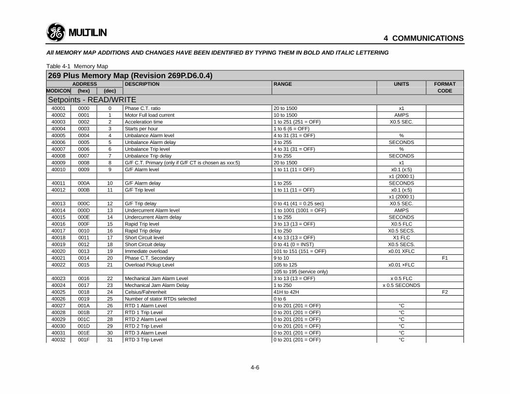
4 COMMUNICATIONS
4-6
All MEMORY MAP ADDITIONS AND CHANGES HAVE BEEN IDENTIFIED BY TYPING THEM IN BOLD AND ITALIC LETTERING
Table 4-1 Memory Map
269 Plus Memory Map (Revision 269P.D6.0.4)ADDRESS DESCRIPTION RANGE UNITS FORMAT
MODICON (hex) (dec) CODE
Setpoints - READ/WRITE40001 0000 0 Phase C.T. ratio 20 to 1500 x140002 0001 1 Motor Full load current 10 to 1500 AMPS40003 0002 2 Acceleration time 1 to 251 (251 = OFF) X0.5 SEC.40004 0003 3 Starts per hour 1 to 6 (6 = OFF)40005 0004 4 Unbalance Alarm level 4 to 31 (31 = OFF) %40006 0005 5 Unbalance Alarm delay 3 to 255 SECONDS40007 0006 6 Unbalance Trip level 4 to 31 (31 = OFF) %40008 0007 7 Unbalance Trip delay 3 to 255 SECONDS40009 0008 8 G/F C.T. Primary (only if G/F CT is chosen as xxx:5) 20 to 1500 x140010 0009 9 G/F Alarm level 1 to 11 (11 = OFF) x0.1 (x:5)
x1 (2000:1)40011 000A 10 G/F Alarm delay 1 to 255 SECONDS40012 000B 11 G/F Trip level 1 to 11 (11 = OFF) x0.1 (x:5)
x1 (2000:1)40013 000C 12 G/F Trip delay 0 to 41 (41 = 0.25 sec) X0.5 SEC.40014 000D 13 Undercurrent Alarm level 1 to 1001 (1001 = OFF) AMPS40015 000E 14 Undercurrent Alarm delay 1 to 255 SECONDS40016 000F 15 Rapid Trip level 3 to 13 (13 = OFF) X0.5 FLC40017 0010 16 Rapid Trip delay 1 to 250 X0.5 SECS.40018 0011 17 Short Circuit level 4 to 13 (13 = OFF) X1 FLC40019 0012 18 Short Circuit delay 0 to 41 (0 = INST) X0.5 SECS.40020 0013 19 Immediate overload 101 to 151 (151 = OFF) x0.01 XFLC40021 0014 20 Phase C.T. Secondary 9 to 10 F140022 0015 21 Overload Pickup Level 105 to 125 x0.01 ×FLC
105 to 195 (service only)40023 0016 22 Mechanical Jam Alarm Level 3 to 13 (13 = OFF) x 0.5 FLC40024 0017 23 Mechanical Jam Alarm Delay 1 to 250 x 0.5 SECONDS40025 0018 24 Celsius/Fahrenheit 41H to 42H F240026 0019 25 Number of stator RTDs selected 0 to 640027 001A 26 RTD 1 Alarm Level 0 to 201 (201 = OFF) °C40028 001B 27 RTD 1 Trip Level 0 to 201 (201 = OFF) °C40029 001C 28 RTD 2 Alarm Level 0 to 201 (201 = OFF) °C40030 001D 29 RTD 2 Trip Level 0 to 201 (201 = OFF) °C40031 001E 30 RTD 3 Alarm Level 0 to 201 (201 = OFF) °C40032 001F 31 RTD 3 Trip Level 0 to 201 (201 = OFF) °C
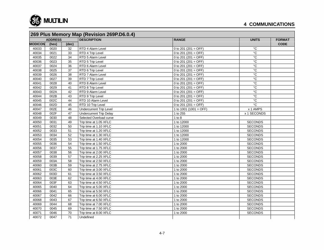
4 COMMUNICATIONS
4-7
269 Plus Memory Map (Revision 269P.D6.0.4)ADDRESS DESCRIPTION RANGE UNITS FORMAT
MODICON (hex) (dec) CODE40033 0020 32 RTD 4 Alarm Level 0 to 201 (201 = OFF) °C40034 0021 33 RTD 4 Trip Level 0 to 201 (201 = OFF) °C40035 0022 34 RTD 5 Alarm Level 0 to 201 (201 = OFF) °C40036 0023 35 RTD 5 Trip Level 0 to 201 (201 = OFF) °C40037 0024 36 RTD 6 Alarm Level 0 to 201 (201 = OFF) °C40038 0025 37 RTD 6 Trip Level 0 to 201 (201 = OFF) °C40039 0026 38 RTD 7 Alarm Level 0 to 201 (201 = OFF) °C40040 0027 39 RTD 7 Trip Level 0 to 201 (201 = OFF) °C40041 0028 40 RTD 8 Alarm Level 0 to 201 (201 = OFF) °C40042 0029 41 RTD 8 Trip Level 0 to 201 (201 = OFF) °C40043 002A 42 RTD 9 Alarm Level 0 to 201 (201 = OFF) °C40044 002B 43 RTD 9 Trip Level 0 to 201 (201 = OFF) °C40045 002C 44 RTD 10 Alarm Level 0 to 201 (201 = OFF) °C40046 002D 45 RTD 10 Trip Level 0 to 201 (201 = OFF) °C40047 002E 46 Undercurrent Trip Level 1 to 1001 (1001 = OFF) x 1 AMPS40048 002F 47 Undercurrent Trip Delay 1 to 255 x 1 SECONDS40049 0030 48 Selected Overload curve 1 to 840050 0031 49 Trip time at 1.05 XFLC 1 to 12000 SECONDS40051 0032 50 Trip time at 1.10 XFLC 1 to 12000 SECONDS40052 0033 51 Trip time at 1.20 XFLC 1 to 12000 SECONDS40053 0034 52 Trip time at 1.30 XFLC 1 to 12000 SECONDS40054 0035 53 Trip time at 1.40 XFLC 1 to 12000 SECONDS40055 0036 54 Trip time at 1.50 XFLC 1 to 2000 SECONDS40056 0037 55 Trip time at 1.75 XFLC 1 to 2000 SECONDS40057 0038 56 Trip time at 2.00 XFLC 1 to 2000 SECONDS40058 0039 57 Trip time at 2.25 XFLC 1 to 2000 SECONDS40059 003A 58 Trip time at 2.50 XFLC 1 to 2000 SECONDS40060 003B 59 Trip time at 2.75 XFLC 1 to 2000 SECONDS40061 003C 60 Trip time at 3.00 XFLC 1 to 2000 SECONDS40062 003D 61 Trip time at 3.50 XFLC 1 to 2000 SECONDS40063 003E 62 Trip time at 4.00 XFLC 1 to 2000 SECONDS40064 003F 63 Trip time at 4.50 XFLC 1 to 2000 SECONDS40065 0040 64 Trip time at 5.00 XFLC 1 to 2000 SECONDS40066 0041 65 Trip time at 5.50 XFLC 1 to 2000 SECONDS40067 0042 66 Trip time at 6.00 XFLC 1 to 2000 SECONDS40068 0043 67 Trip time at 6.50 XFLC 1 to 2000 SECONDS40069 0044 68 Trip time at 7.00 XFLC 1 to 2000 SECONDS40070 0045 69 Trip time at 7.50 XFLC 1 to 2000 SECONDS40071 0046 70 Trip time at 8.00 XFLC 1 to 2000 SECONDS40072 0047 71 Undefined
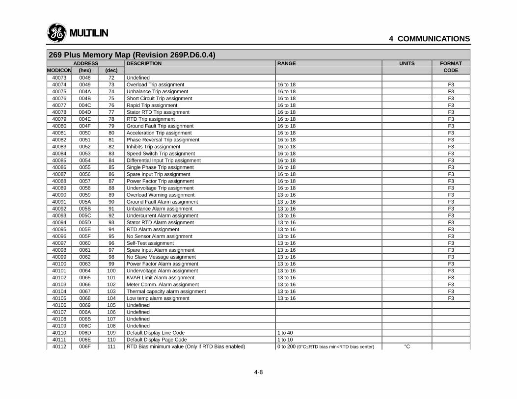
4 COMMUNICATIONS
4-8
269 Plus Memory Map (Revision 269P.D6.0.4)ADDRESS DESCRIPTION RANGE UNITS FORMAT
MODICON (hex) (dec) CODE40073 0048 72 Undefined40074 0049 73 Overload Trip assignment 16 to 18 F340075 004A 74 Unbalance Trip assignment 16 to 18 F340076 004B 75 Short Circuit Trip assignment 16 to 18 F340077 004C 76 Rapid Trip assignment 16 to 18 F340078 004D 77 Stator RTD Trip assignment 16 to 18 F340079 004E 78 RTD Trip assignment 16 to 18 F340080 004F 79 Ground Fault Trip assignment 16 to 18 F340081 0050 80 Acceleration Trip assignment 16 to 18 F340082 0051 81 Phase Reversal Trip assignment 16 to 18 F340083 0052 82 Inhibits Trip assignment 16 to 18 F340084 0053 83 Speed Switch Trip assignment 16 to 18 F340085 0054 84 Differential Input Trip assignment 16 to 18 F340086 0055 85 Single Phase Trip assignment 16 to 18 F340087 0056 86 Spare Input Trip assignment 16 to 18 F340088 0057 87 Power Factor Trip assignment 16 to 18 F340089 0058 88 Undervoltage Trip assignment 16 to 18 F340090 0059 89 Overload Warning assignment 13 to 16 F340091 005A 90 Ground Fault Alarm assignment 13 to 16 F340092 005B 91 Unbalance Alarm assignment 13 to 16 F340093 005C 92 Undercurrent Alarm assignment 13 to 16 F340094 005D 93 Stator RTD Alarm assignment 13 to 16 F340095 005E 94 RTD Alarm assignment 13 to 16 F340096 005F 95 No Sensor Alarm assignment 13 to 16 F340097 0060 96 Self-Test assignment 13 to 16 F340098 0061 97 Spare Input Alarm assignment 13 to 16 F340099 0062 98 No Slave Message assignment 13 to 16 F340100 0063 99 Power Factor Alarm assignment 13 to 16 F340101 0064 100 Undervoltage Alarm assignment 13 to 16 F340102 0065 101 KVAR Limit Alarm assignment 13 to 16 F340103 0066 102 Meter Comm. Alarm assignment 13 to 16 F340104 0067 103 Thermal capacity alarm assignment 13 to 16 F340105 0068 104 Low temp alarm assignment 13 to 16 F340106 0069 105 Undefined40107 006A 106 Undefined40108 006B 107 Undefined40109 006C 108 Undefined40110 006D 109 Default Display Line Code 1 to 4040111 006E 110 Default Display Page Code 1 to 1040112 006F 111 RTD Bias minimum value (Only if RTD Bias enabled) 0 to 200 (0°C≤RTD bias min<RTD bias center) °C
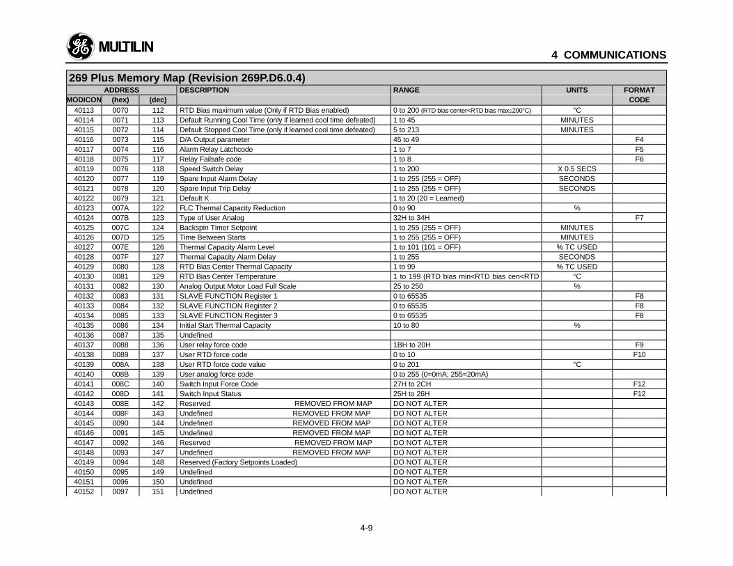
4 COMMUNICATIONS
4-9
269 Plus Memory Map (Revision 269P.D6.0.4)ADDRESS DESCRIPTION RANGE UNITS FORMAT
MODICON (hex) (dec) CODE40113 0070 112 RTD Bias maximum value (Only if RTD Bias enabled) 0 to 200 (RTD bias center<RTD bias max≤200°C) °C40114 0071 113 Default Running Cool Time (only if learned cool time defeated) 1 to 45 MINUTES40115 0072 114 Default Stopped Cool Time (only if learned cool time defeated) 5 to 213 MINUTES40116 0073 115 D/A Output parameter 45 to 49 F440117 0074 116 Alarm Relay Latchcode 1 to 7 F540118 0075 117 Relay Failsafe code 1 to 8 F640119 0076 118 Speed Switch Delay 1 to 200 X 0.5 SECS40120 0077 119 Spare Input Alarm Delay 1 to 255 (255 = OFF) SECONDS40121 0078 120 Spare Input Trip Delay 1 to 255 (255 = OFF) SECONDS40122 0079 121 Default K 1 to 20 (20 = Learned)40123 007A 122 FLC Thermal Capacity Reduction 0 to 90 %40124 007B 123 Type of User Analog 32H to 34H F740125 007C 124 Backspin Timer Setpoint 1 to 255 (255 = OFF) MINUTES40126 007D 125 Time Between Starts 1 to 255 (255 = OFF) MINUTES40127 007E 126 Thermal Capacity Alarm Level 1 to 101 (101 = OFF) % TC USED40128 007F 127 Thermal Capacity Alarm Delay 1 to 255 SECONDS40129 0080 128 RTD Bias Center Thermal Capacity 1 to 99 % TC USED40130 0081 129 RTD Bias Center Temperature 1 to 199 (RTD bias min<RTD bias cen<RTD
bias max)°C
40131 0082 130 Analog Output Motor Load Full Scale 25 to 250 %40132 0083 131 SLAVE FUNCTION Register 1 0 to 65535 F840133 0084 132 SLAVE FUNCTION Register 2 0 to 65535 F840134 0085 133 SLAVE FUNCTION Register 3 0 to 65535 F840135 0086 134 Initial Start Thermal Capacity 10 to 80 %40136 0087 135 Undefined40137 0088 136 User relay force code 1BH to 20H F940138 0089 137 User RTD force code 0 to 10 F1040139 008A 138 User RTD force code value 0 to 201 °C40140 008B 139 User analog force code 0 to 255 (0=0mA; 255=20mA)40141 008C 140 Switch Input Force Code 27H to 2CH F1240142 008D 141 Switch Input Status 25H to 26H F1240143 008E 142 Reserved REMOVED FROM MAP DO NOT ALTER40144 008F 143 Undefined REMOVED FROM MAP DO NOT ALTER40145 0090 144 Undefined REMOVED FROM MAP DO NOT ALTER40146 0091 145 Undefined REMOVED FROM MAP DO NOT ALTER40147 0092 146 Reserved REMOVED FROM MAP DO NOT ALTER40148 0093 147 Undefined REMOVED FROM MAP DO NOT ALTER40149 0094 148 Reserved (Factory Setpoints Loaded) DO NOT ALTER40150 0095 149 Undefined DO NOT ALTER40151 0096 150 Undefined DO NOT ALTER40152 0097 151 Undefined DO NOT ALTER
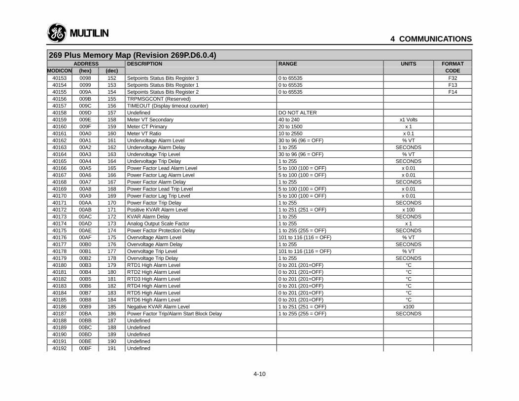
4 COMMUNICATIONS
4-10
269 Plus Memory Map (Revision 269P.D6.0.4)ADDRESS DESCRIPTION RANGE UNITS FORMAT
MODICON (hex) (dec) CODE40153 0098 152 Setpoints Status Bits Register 3 0 to 65535 F3240154 0099 153 Setpoints Status Bits Register 1 0 to 65535 F1340155 009A 154 Setpoints Status Bits Register 2 0 to 65535 F1440156 009B 155 TRPMSGCONT (Reserved)40157 009C 156 TIMEOUT (Display timeout counter)40158 009D 157 Undefined DO NOT ALTER40159 009E 158 Meter VT Secondary 40 to 240 x1 Volts40160 009F 159 Meter CT Primary 20 to 1500 x 140161 00A0 160 Meter VT Ratio 10 to 2550 x 0.140162 00A1 161 Undervoltage Alarm Level 30 to 96 (96 = OFF) % VT40163 00A2 162 Undervoltage Alarm Delay 1 to 255 SECONDS40164 00A3 163 Undervoltage Trip Level 30 to 96 (96 = OFF) % VT40165 00A4 164 Undervoltage Trip Delay 1 to 255 SECONDS40166 00A5 165 Power Factor Lead Alarm Level 5 to 100 (100 = OFF) x 0.0140167 00A6 166 Power Factor Lag Alarm Level 5 to 100 (100 = OFF) x 0.0140168 00A7 167 Power Factor Alarm Delay 1 to 255 SECONDS40169 00A8 168 Power Factor Lead Trip Level 5 to 100 (100 = OFF) x 0.0140170 00A9 169 Power Factor Lag Trip Level 5 to 100 (100 = OFF) x 0.0140171 00AA 170 Power Factor Trip Delay 1 to 255 SECONDS40172 00AB 171 Positive KVAR Alarm Level 1 to 251 (251 = OFF) x 10040173 00AC 172 KVAR Alarm Delay 1 to 255 SECONDS40174 00AD 173 Analog Output Scale Factor 1 to 255 x 140175 00AE 174 Power Factor Protection Delay 1 to 255 (255 = OFF) SECONDS40176 00AF 175 Overvoltage Alarm Level 101 to 116 (116 = OFF) % VT40177 00B0 176 Overvoltage Alarm Delay 1 to 255 SECONDS40178 00B1 177 Overvoltage Trip Level 101 to 116 (116 = OFF) % VT40179 00B2 178 Overvoltage Trip Delay 1 to 255 SECONDS40180 00B3 179 RTD1 High Alarm Level 0 to 201 (201=OFF) °C40181 00B4 180 RTD2 High Alarm Level 0 to 201 (201=OFF) °C40182 00B5 181 RTD3 High Alarm Level 0 to 201 (201=OFF) °C40183 00B6 182 RTD4 High Alarm Level 0 to 201 (201=OFF) °C40184 00B7 183 RTD5 High Alarm Level 0 to 201 (201=OFF) °C40185 00B8 184 RTD6 High Alarm Level 0 to 201 (201=OFF) °C40186 00B9 185 Negative KVAR Alarm Level 1 to 251 (251 = OFF) x10040187 00BA 186 Power Factor Trip/Alarm Start Block Delay 1 to 255 (255 = OFF) SECONDS40188 00BB 187 Undefined40189 00BC 188 Undefined40190 00BD 189 Undefined40191 00BE 190 Undefined40192 00BF 191 Undefined

4 COMMUNICATIONS
4-11
269 Plus Memory Map (Revision 269P.D6.0.4)ADDRESS DESCRIPTION RANGE UNITS FORMAT
MODICON (hex) (dec) CODE40193 00C0 192 Overvoltage Trip Assignment 16 to 18 F340194 00C1 193 Undercurrent Trip Assignment 16 to 18 F340195 00C2 194 Undefined40196 00C3 195 Undefined40197 00C4 196 Undefined40198 00C5 197 Undefined40199 00C6 198 Undefined40200 00C7 199 Undefined40201 00C8 200 Overvoltage Alarm Assignment 13 to 16 F340202 00C9 201 Mechanical Jam Alarm Assignment 13 to 16 F340203 00CA 202 Undefined40204 00CB 203 Undefined40205 00CC 204 Undefined40206 00CD 205 Undefined40207 00CE 206 Stator RTD High Alarm Assignment 13 to 16 F340208 00CF 207 RTD High Alarm Assignment 13 to 16 F340209 00D0 208 Undefined40210 00D1 209 Undefined40211 00D2 210 Undefined40212 00D3 211 Undefined40213 00D4 212 Undefined40214 00D5 213 Undefined40215 00D6 214 Undefined40216 00D7 215 Undefined40217 00D8 216 Undefined40218 00D9 217 Undefined40219 00DA 218 Undefined40220 00DB 219 Undefined40221 00DC 220 Undefined40222 00DD 221 Undefined40223 00DE 222 Undefined40224 00DF 223 Undefined40225 00E0 224 Undefined40226 00E1 225 Undefined40227 00E2 226 Undefined40228 00E3 227 Undefined40229 00E4 228 Undefined40230 00E5 229 Undefined40231 00E6 230 Undefined40232 00E7 231 Undefined
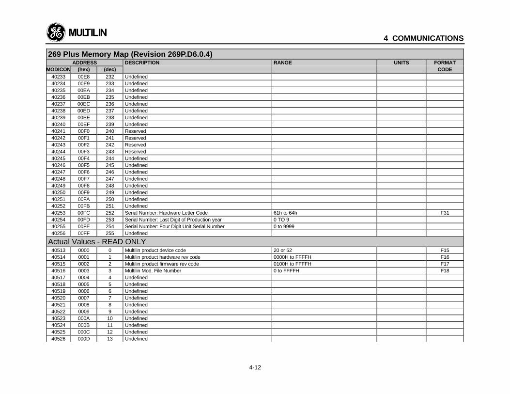
4 COMMUNICATIONS
4-12
269 Plus Memory Map (Revision 269P.D6.0.4)ADDRESS DESCRIPTION RANGE UNITS FORMAT
MODICON (hex) (dec) CODE40233 00E8 232 Undefined40234 00E9 233 Undefined40235 00EA 234 Undefined40236 00EB 235 Undefined40237 00EC 236 Undefined40238 00ED 237 Undefined40239 00EE 238 Undefined40240 00EF 239 Undefined40241 00F0 240 Reserved40242 00F1 241 Reserved40243 00F2 242 Reserved40244 00F3 243 Reserved40245 00F4 244 Undefined40246 00F5 245 Undefined40247 00F6 246 Undefined40248 00F7 247 Undefined40249 00F8 248 Undefined40250 00F9 249 Undefined40251 00FA 250 Undefined40252 00FB 251 Undefined40253 00FC 252 Serial Number: Hardware Letter Code 61h to 64h F3140254 00FD 253 Serial Number: Last Digit of Production year 0 TO 940255 00FE 254 Serial Number: Four Digit Unit Serial Number 0 to 999940256 00FF 255 Undefined
Actual Values - READ ONLY40513 0000 0 Multilin product device code 20 or 52 F1540514 0001 1 Multilin product hardware rev code 0000H to FFFFH F1640515 0002 2 Multilin product firmware rev code 0100H to FFFFH F1740516 0003 3 Multilin Mod. File Number 0 to FFFFH F1840517 0004 4 Undefined40518 0005 5 Undefined40519 0006 6 Undefined40520 0007 7 Undefined40521 0008 8 Undefined40522 0009 9 Undefined40523 000A 10 Undefined40524 000B 11 Undefined40525 000C 12 Undefined40526 000D 13 Undefined
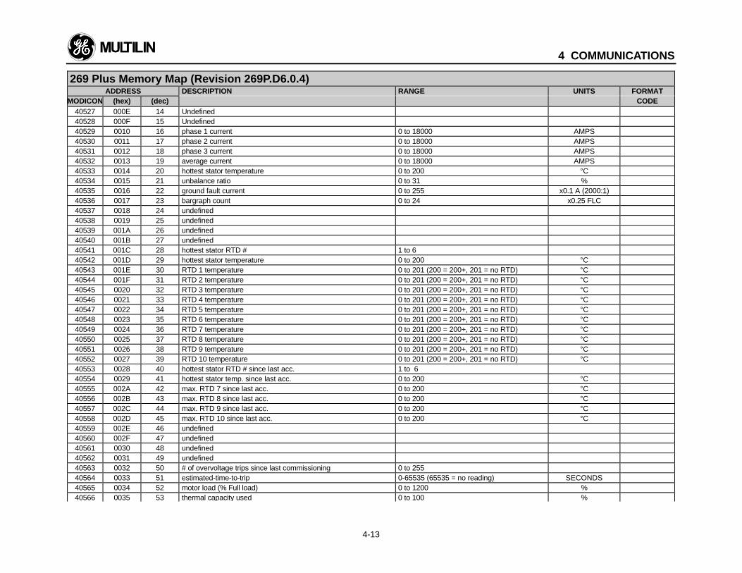
4 COMMUNICATIONS
4-13
269 Plus Memory Map (Revision 269P.D6.0.4)ADDRESS DESCRIPTION RANGE UNITS FORMAT
MODICON (hex) (dec) CODE40527 000E 14 Undefined40528 000F 15 Undefined40529 0010 16 phase 1 current 0 to 18000 AMPS40530 0011 17 phase 2 current 0 to 18000 AMPS40531 0012 18 phase 3 current 0 to 18000 AMPS40532 0013 19 average current 0 to 18000 AMPS40533 0014 20 hottest stator temperature 0 to 200 °C40534 0015 21 unbalance ratio 0 to 31 %40535 0016 22 ground fault current 0 to 255 x0.1 A (2000:1)40536 0017 23 bargraph count 0 to 24 x0.25 FLC40537 0018 24 undefined40538 0019 25 undefined40539 001A 26 undefined40540 001B 27 undefined40541 001C 28 hottest stator RTD # 1 to 640542 001D 29 hottest stator temperature 0 to 200 °C40543 001E 30 RTD 1 temperature 0 to 201 (200 = 200+, 201 = no RTD) °C40544 001F 31 RTD 2 temperature 0 to 201 (200 = 200+, 201 = no RTD) °C40545 0020 32 RTD 3 temperature 0 to 201 (200 = 200+, 201 = no RTD) °C40546 0021 33 RTD 4 temperature 0 to 201 (200 = 200+, 201 = no RTD) °C40547 0022 34 RTD 5 temperature 0 to 201 (200 = 200+, 201 = no RTD) °C40548 0023 35 RTD 6 temperature 0 to 201 (200 = 200+, 201 = no RTD) °C40549 0024 36 RTD 7 temperature 0 to 201 (200 = 200+, 201 = no RTD) °C40550 0025 37 RTD 8 temperature 0 to 201 (200 = 200+, 201 = no RTD) °C40551 0026 38 RTD 9 temperature 0 to 201 (200 = 200+, 201 = no RTD) °C40552 0027 39 RTD 10 temperature 0 to 201 (200 = 200+, 201 = no RTD) °C40553 0028 40 hottest stator RTD # since last acc. 1 to 640554 0029 41 hottest stator temp. since last acc. 0 to 200 °C40555 002A 42 max. RTD 7 since last acc. 0 to 200 °C40556 002B 43 max. RTD 8 since last acc. 0 to 200 °C40557 002C 44 max. RTD 9 since last acc. 0 to 200 °C40558 002D 45 max. RTD 10 since last acc. 0 to 200 °C40559 002E 46 undefined40560 002F 47 undefined40561 0030 48 undefined40562 0031 49 undefined40563 0032 50 # of overvoltage trips since last commissioning 0 to 25540564 0033 51 estimated-time-to-trip 0-65535 (65535 = no reading) SECONDS40565 0034 52 motor load (% Full load) 0 to 1200 %40566 0035 53 thermal capacity used 0 to 100 %
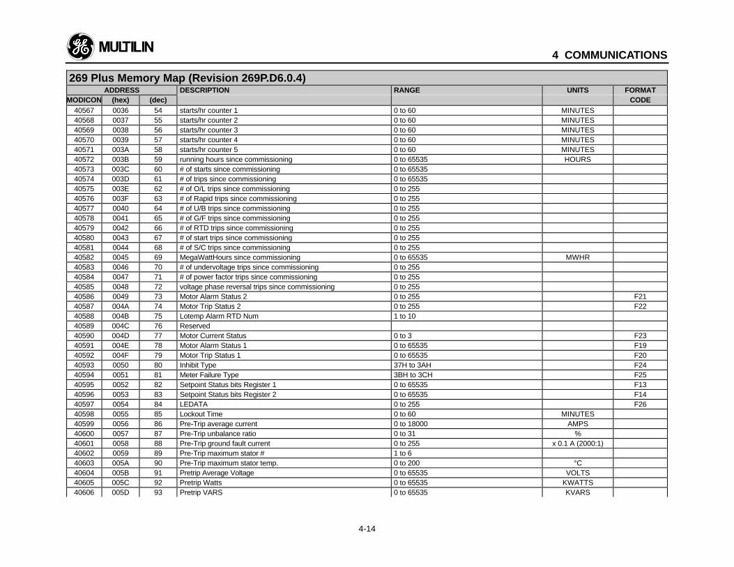
4 COMMUNICATIONS
4-14
269 Plus Memory Map (Revision 269P.D6.0.4)ADDRESS DESCRIPTION RANGE UNITS FORMAT
MODICON (hex) (dec) CODE40567 0036 54 starts/hr counter 1 0 to 60 MINUTES40568 0037 55 starts/hr counter 2 0 to 60 MINUTES40569 0038 56 starts/hr counter 3 0 to 60 MINUTES40570 0039 57 starts/hr counter 4 0 to 60 MINUTES40571 003A 58 starts/hr counter 5 0 to 60 MINUTES40572 003B 59 running hours since commissioning 0 to 65535 HOURS40573 003C 60 # of starts since commissioning 0 to 6553540574 003D 61 # of trips since commissioning 0 to 6553540575 003E 62 # of O/L trips since commissioning 0 to 25540576 003F 63 # of Rapid trips since commissioning 0 to 25540577 0040 64 # of U/B trips since commissioning 0 to 25540578 0041 65 # of G/F trips since commissioning 0 to 25540579 0042 66 # of RTD trips since commissioning 0 to 25540580 0043 67 # of start trips since commissioning 0 to 25540581 0044 68 # of S/C trips since commissioning 0 to 25540582 0045 69 MegaWattHours since commissioning 0 to 65535 MWHR40583 0046 70 # of undervoltage trips since commissioning 0 to 25540584 0047 71 # of power factor trips since commissioning 0 to 25540585 0048 72 voltage phase reversal trips since commissioning 0 to 25540586 0049 73 Motor Alarm Status 2 0 to 255 F2140587 004A 74 Motor Trip Status 2 0 to 255 F2240588 004B 75 Lotemp Alarm RTD Num 1 to 1040589 004C 76 Reserved40590 004D 77 Motor Current Status 0 to 3 F2340591 004E 78 Motor Alarm Status 1 0 to 65535 F1940592 004F 79 Motor Trip Status 1 0 to 65535 F2040593 0050 80 Inhibit Type 37H to 3AH F2440594 0051 81 Meter Failure Type 3BH to 3CH F2540595 0052 82 Setpoint Status bits Register 1 0 to 65535 F1340596 0053 83 Setpoint Status bits Register 2 0 to 65535 F1440597 0054 84 LEDATA 0 to 255 F2640598 0055 85 Lockout Time 0 to 60 MINUTES40599 0056 86 Pre-Trip average current 0 to 18000 AMPS40600 0057 87 Pre-Trip unbalance ratio 0 to 31 %40601 0058 88 Pre-Trip ground fault current 0 to 255 x 0.1 A (2000:1)40602 0059 89 Pre-Trip maximum stator # 1 to 640603 005A 90 Pre-Trip maximum stator temp. 0 to 200 °C40604 005B 91 Pretrip Average Voltage 0 to 65535 VOLTS40605 005C 92 Pretrip Watts 0 to 65535 KWATTS40606 005D 93 Pretrip VARS 0 to 65535 KVARS
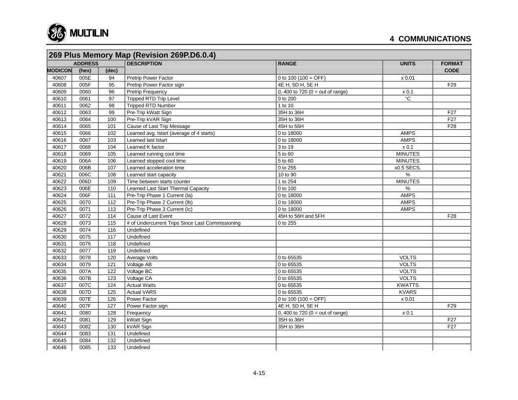
4 COMMUNICATIONS
4-15
269 Plus Memory Map (Revision 269P.D6.0.4)ADDRESS DESCRIPTION RANGE UNITS FORMAT
MODICON (hex) (dec) CODE40607 005E 94 Pretrip Power Factor 0 to 100 (100 = OFF) x 0.0140608 005F 95 Pretrip Power Factor sign 4E H, 5D H, 5E H F2940609 0060 96 Pretrip Frequency 0, 400 to 720 (0 = out of range) x 0.140610 0061 97 Tripped RTD Trip Level 0 to 200 °C40611 0062 98 Tripped RTD Number 1 to 1040612 0063 99 Pre-Trip kWatt Sign 35H to 36H F2740613 0064 100 Pre-Trip kVAR Sign 35H to 36H F2740614 0065 101 Cause of Last Trip Message 45H to 56H F2840615 0066 102 Learned avg. Istart (average of 4 starts) 0 to 18000 AMPS40616 0067 103 Learned last Istart 0 to 18000 AMPS40617 0068 104 Learned K factor 3 to 19 x 0.140618 0069 105 Learned running cool time 5 to 60 MINUTES40619 006A 106 Learned stopped cool time 5 to 60 MINUTES40620 006B 107 Learned acceleration time 0 to 255 x0.5 SECS.40621 006C 108 Learned start capacity 10 to 90 %40622 006D 109 Time between starts counter 1 to 254 MINUTES40623 006E 110 Learned Last Start Thermal Capacity 0 to 100 %40624 006F 111 Pre-Trip Phase 1 Current (Ia) 0 to 18000 AMPS40625 0070 112 Pre-Trip Phase 2 Current (Ib) 0 to 18000 AMPS40626 0071 113 Pre-Trip Phase 3 Current (Ic) 0 to 18000 AMPS40627 0072 114 Cause of Last Event 45H to 56H and 5FH F2840628 0073 115 # of Undercurrent Trips Since Last Commissioning 0 to 25540629 0074 116 Undefined40630 0075 117 Undefined40631 0076 118 Undefined40632 0077 119 Undefined40633 0078 120 Average Volts 0 to 65535 VOLTS40634 0079 121 Voltage AB 0 to 65535 VOLTS40635 007A 122 Voltage BC 0 to 65535 VOLTS40636 007B 123 Voltage CA 0 to 65535 VOLTS40637 007C 124 Actual Watts 0 to 65535 KWATTS40638 007D 125 Actual VARS 0 to 65535 KVARS40639 007E 126 Power Factor 0 to 100 (100 = OFF) x 0.0140640 007F 127 Power Factor sign 4E H, 5D H, 5E H F2940641 0080 128 Frequency 0, 400 to 720 (0 = out of range) x 0.140642 0081 129 kWatt Sign 35H to 36H F2740643 0082 130 kVAR Sign 35H to 36H F2740644 0083 131 Undefined40645 0084 132 Undefined40646 0085 133 Undefined
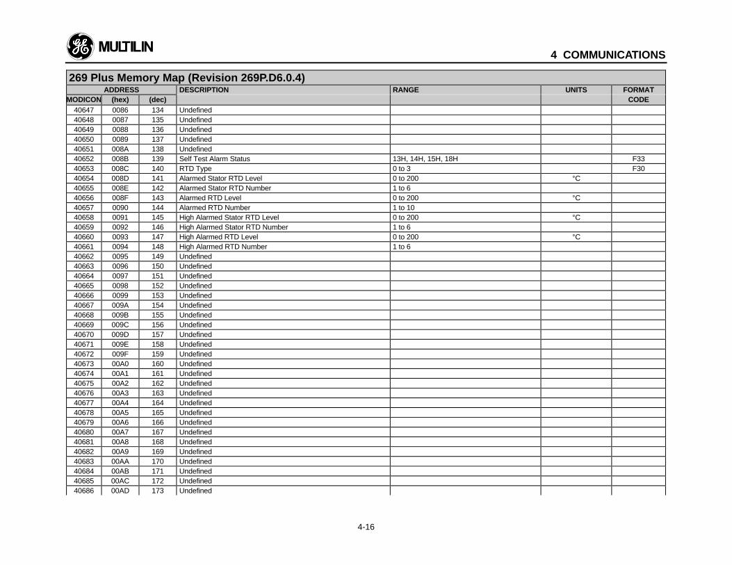
4 COMMUNICATIONS
4-16
269 Plus Memory Map (Revision 269P.D6.0.4)ADDRESS DESCRIPTION RANGE UNITS FORMAT
MODICON (hex) (dec) CODE40647 0086 134 Undefined40648 0087 135 Undefined40649 0088 136 Undefined40650 0089 137 Undefined40651 008A 138 Undefined40652 008B 139 Self Test Alarm Status 13H, 14H, 15H, 18H F3340653 008C 140 RTD Type 0 to 3 F3040654 008D 141 Alarmed Stator RTD Level 0 to 200 °C40655 008E 142 Alarmed Stator RTD Number 1 to 640656 008F 143 Alarmed RTD Level 0 to 200 °C40657 0090 144 Alarmed RTD Number 1 to 1040658 0091 145 High Alarmed Stator RTD Level 0 to 200 °C40659 0092 146 High Alarmed Stator RTD Number 1 to 640660 0093 147 High Alarmed RTD Level 0 to 200 °C40661 0094 148 High Alarmed RTD Number 1 to 640662 0095 149 Undefined40663 0096 150 Undefined40664 0097 151 Undefined40665 0098 152 Undefined40666 0099 153 Undefined40667 009A 154 Undefined40668 009B 155 Undefined40669 009C 156 Undefined40670 009D 157 Undefined40671 009E 158 Undefined40672 009F 159 Undefined40673 00A0 160 Undefined40674 00A1 161 Undefined40675 00A2 162 Undefined40676 00A3 163 Undefined40677 00A4 164 Undefined40678 00A5 165 Undefined40679 00A6 166 Undefined40680 00A7 167 Undefined40681 00A8 168 Undefined40682 00A9 169 Undefined40683 00AA 170 Undefined40684 00AB 171 Undefined40685 00AC 172 Undefined40686 00AD 173 Undefined

4 COMMUNICATIONS
4-17
269 Plus Memory Map (Revision 269P.D6.0.4)ADDRESS DESCRIPTION RANGE UNITS FORMAT
MODICON (hex) (dec) CODE40687 00AE 174 Undefined40688 00AF 175 Undefined40689 00B0 176 Undefined40690 00B1 177 Undefined40691 00B2 178 Undefined40692 00B3 179 Undefined40693 00B4 180 Undefined40694 00B5 181 Undefined40695 00B6 182 Undefined40696 00B7 183 Undefined40697 00B8 184 Undefined40698 00B9 185 Undefined40699 00BA 186 Undefined40700 00BB 187 Undefined40701 00BC 188 Undefined40702 00BD 189 Undefined40703 00BE 190 Undefined40704 00BF 191 Undefined40705 00C0 192 Undefined40706 00C1 193 Undefined40707 00C2 194 Undefined40708 00C3 195 Undefined40709 00C4 196 Undefined40710 00C5 197 Undefined40711 00C6 198 Undefined40712 00C7 199 Undefined40713 00C8 200 Undefined40714 00C9 201 Undefined40715 00CA 202 Undefined40716 00CB 203 Undefined40717 00CC 204 Undefined40718 00CD 205 Undefined40719 00CE 206 Undefined40720 00CF 207 Undefined40721 00D0 208 Undefined40722 00D1 209 Undefined40723 00D2 210 Undefined40724 00D3 211 Undefined40725 00D4 212 Undefined40726 00D5 213 Undefined
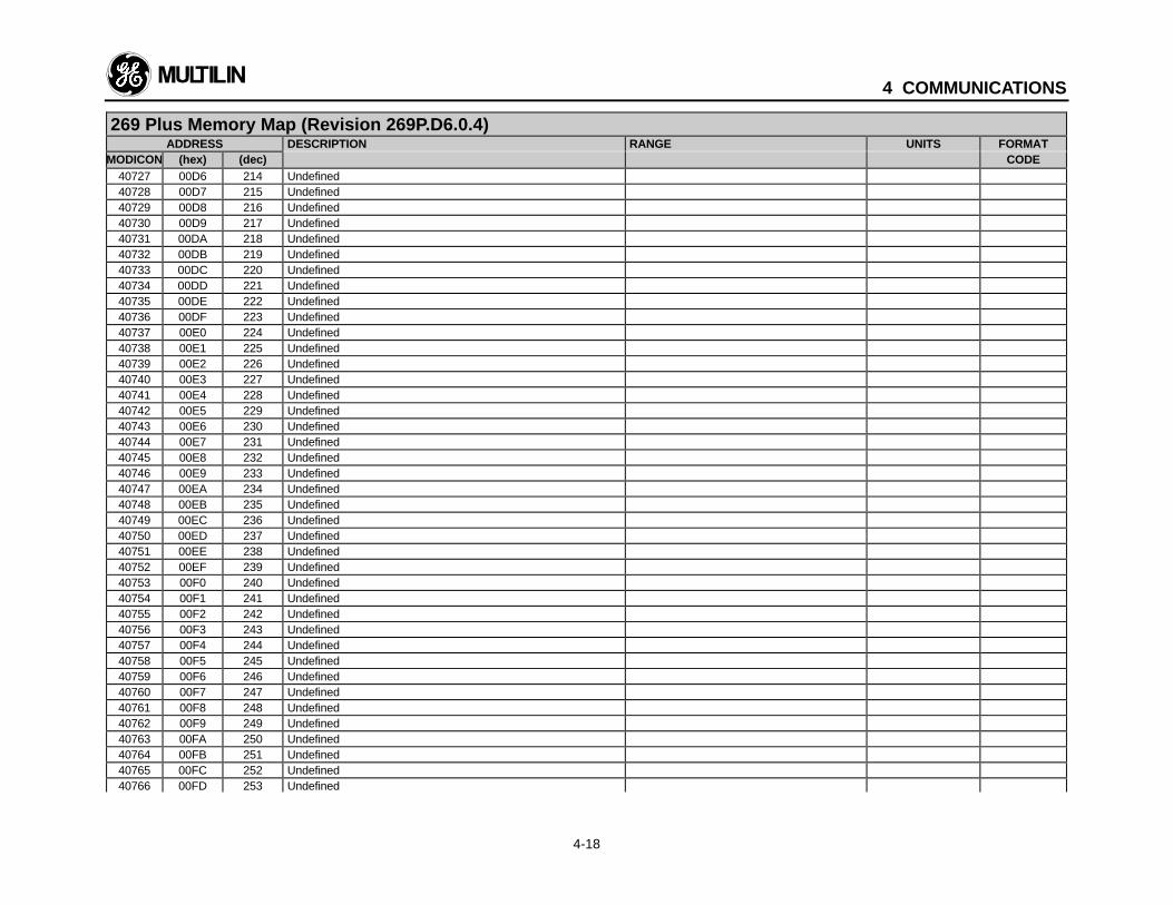
4 COMMUNICATIONS
4-18
269 Plus Memory Map (Revision 269P.D6.0.4)ADDRESS DESCRIPTION RANGE UNITS FORMAT
MODICON (hex) (dec) CODE40727 00D6 214 Undefined40728 00D7 215 Undefined40729 00D8 216 Undefined40730 00D9 217 Undefined40731 00DA 218 Undefined40732 00DB 219 Undefined40733 00DC 220 Undefined40734 00DD 221 Undefined40735 00DE 222 Undefined40736 00DF 223 Undefined40737 00E0 224 Undefined40738 00E1 225 Undefined40739 00E2 226 Undefined40740 00E3 227 Undefined40741 00E4 228 Undefined40742 00E5 229 Undefined40743 00E6 230 Undefined40744 00E7 231 Undefined40745 00E8 232 Undefined40746 00E9 233 Undefined40747 00EA 234 Undefined40748 00EB 235 Undefined40749 00EC 236 Undefined40750 00ED 237 Undefined40751 00EE 238 Undefined40752 00EF 239 Undefined40753 00F0 240 Undefined40754 00F1 241 Undefined40755 00F2 242 Undefined40756 00F3 243 Undefined40757 00F4 244 Undefined40758 00F5 245 Undefined40759 00F6 246 Undefined40760 00F7 247 Undefined40761 00F8 248 Undefined40762 00F9 249 Undefined40763 00FA 250 Undefined40764 00FB 251 Undefined40765 00FC 252 Undefined40766 00FD 253 Undefined
4 COMMUNICATIONS
4-19
269 Plus Memory Map (Revision 269P.D6.0.4)ADDRESS DESCRIPTION RANGE UNITS FORMAT
MODICON (hex) (dec) CODE40767 00FE 254 Undefined40768 00FF 255 Undefined
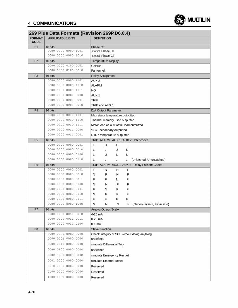
4 COMMUNICATIONS
4-20
269 Plus Data Formats (Revision 269P.D6.0.4)FORMAT APPLICABLE BITS DEFINITION
CODE
F1 16 bits Phase CT 0000 0000 0000 1001 xxxx:1 Phase CT 0000 0000 0000 1010 xxxx:5 Phase CT
F2 16 bits Temperature Display
0000 0000 0100 0001 Celsius 0000 0000 0100 0010 Fahrenheit
F3 16 bits Relay Assignment
0000 0000 0000 1101 AUX.2 0000 0000 0000 1110 ALARM
0000 0000 0000 1111 NO
0000 0000 0001 0000 AUX.1
0000 0000 0001 0001 TRIP
0000 0000 0001 0010 TRIP and AUX.1
F4 16 bits D/A Output Parameter
0000 0000 0010 1101 Max stator temperature outputted 0000 0000 0010 1110 Thermal memory used outputted
0000 0000 0010 1111 Motor load as a % of full load outputted
0000 0000 0011 0000 % CT secondary outputted
0000 0000 0011 0001 RTD7 temperature outputted
F5 16 bits TRIP ALARM AUX.1 AUX.2 latchcodes
0000 0000 0000 0001 L U U L 0000 0000 0000 0010 L L U L
0000 0000 0000 0100 L U L L
0000 0000 0000 0110 L L L L (L=latched, U=unlatched)
F6 16 bits TRIP ALARM AUX.1 AUX.2 Relay Failsafe Codes
0000 0000 0000 0001 F N N F 0000 0000 0000 0010 N F N F
0000 0000 0000 0011 F F N F
0000 0000 0000 0100 N N F F
0000 0000 0000 0101 F N F F
0000 0000 0000 0110 N F F F
0000 0000 0000 0111 F F F F
0000 0000 0000 1000 N N N F (N=non-failsafe, F=failsafe)
F7 16 bits Analog Output Scale
0000 0000 0011 0010 4-20 mA 0000 0000 0011 0011 0-20 mA
0000 0000 0011 0100 0-1 mA
F8 16 bits Slave Function
0000 0000 0000 0000 Check integrity of SCL without doing anything 0000 0001 0000 0000 undefined
0000 0010 0000 0000 simulate Differential Trip
0000 0100 0000 0000 undefined
0000 1000 0000 0000 simulate Emergency Restart
0001 0000 0000 0000 simulate External Reset
0010 0000 0000 0000 Reserved
0100 0000 0000 0000 Reserved
1000 0000 0000 0000 Reserved
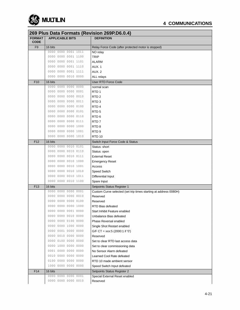
4 COMMUNICATIONS
4-21
269 Plus Data Formats (Revision 269P.D6.0.4)FORMAT APPLICABLE BITS DEFINITION
CODE
F9 16 bits Relay Force Code (after protected motor is stopped)
0000 0000 0001 1011 NO relay 0000 0000 0001 1100 TRIP
0000 0000 0001 1101 ALARM
0000 0000 0001 1110 AUX. 1
0000 0000 0001 1111 AUX. 2
0000 0000 0010 0000 ALL relays
F10 16 bits User RTD Force Code
0000 0000 0000 0000 normal scan 0000 0000 0000 0001 RTD 1
0000 0000 0000 0010 RTD 2
0000 0000 0000 0011 RTD 3
0000 0000 0000 0100 RTD 4
0000 0000 0000 0101 RTD 5
0000 0000 0000 0110 RTD 6
0000 0000 0000 0111 RTD 7
0000 0000 0000 1000 RTD 8
0000 0000 0000 1001 RTD 9
0000 0000 0000 1010 RTD 10
F12 16 bits Switch Input Force Code & Status
0000 0000 0010 0101 Status: short 0000 0000 0010 0110 Status: open
0000 0000 0010 0111 External Reset
0000 0000 0010 1000 Emergency Reset
0000 0000 0010 1001 Access
0000 0000 0010 1010 Speed Switch
0000 0000 0010 1011 Differential Input
0000 0000 0010 1100 Spare Input
F13 16 bits Setpoints Status Register 1
0000 0000 0000 0001 Custom Curve selected (set trip times starting at address 0080H) 0000 0000 0000 0010 Reserved
0000 0000 0000 0100 Reserved
0000 0000 0000 1000 RTD Bias defeated
0000 0000 0001 0000 Start Inhibit Feature enabled
0000 0000 0010 0000 Unbalance Bias defeated
0000 0000 0100 0000 Phase Reversal enabled
0000 0000 1000 0000 Single Shot Restart enabled
0000 0001 0000 0000 G/F CT = xxx:5 (2000:1 if '0')
0000 0010 0000 0000 Reserved
0000 0100 0000 0000 Set to clear RTD last access data
0000 1000 0000 0000 Set to clear commissioning data
0001 0000 0000 0000 No Sensor Alarm defeated
0010 0000 0000 0000 Learned Cool Rate defeated
0100 0000 0000 0000 RTD 10 made ambient sensor
1000 0000 0000 0000 Speed Switch Input defeated
F14 16 bits Setpoints Status Register 2
0000 0000 0000 0001 Special External Reset enabled 0000 0000 0000 0010 Reserved
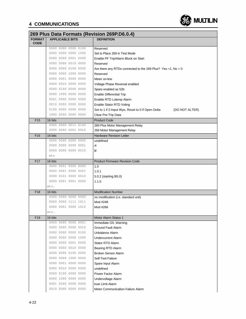
4 COMMUNICATIONS
4-22
269 Plus Data Formats (Revision 269P.D6.0.4)FORMAT APPLICABLE BITS DEFINITION
CODE
0000 0000 0000 0100 Reserved 0000 0000 0000 1000 Set to Place 269 in Test Mode
0000 0000 0001 0000 Enable PF Trip/Alarm Block on Start
0000 0000 0010 0000 Reserved
0000 0000 0100 0000 Are there any RTDs connected to the 269 Plus? Yes =1, No = 0
0000 0000 1000 0000 Reserved
0000 0001 0000 0000 Meter on-line
0000 0010 0000 0000 Voltage Phase Reversal enabled
0000 0100 0000 0000 Spare enabled as 52b
0000 1000 0000 0000 Enable Differential Trip
0001 0000 0000 0000 Enable RTD Lotemp Alarm
0010 0000 0000 0000 Enable Stator RTD Voting
0100 0000 0000 0000 Set to 1 if 2-Input Wye, Reset to 0 if Open Delta (DO NOT ALTER)
1000 0000 0000 0000 Clear Pre-Trip Data
F15 16 bits Product Code
0000 0000 0011 0100 269 Plus Motor Management Relay 0000 0000 0001 0010 269 Motor Management Relay
F16 16 bits Hardware Revision Letter
0000 0000 0000 0000 undefined 0000 0000 0000 0001 A'
0000 0000 0000 0010 B'
etc
F17 16 bits Product Firmware Revision Code
0000 0001 0000 0000 1.0 0000 0001 0000 0001 1.0.1
0000 0101 0000 0010 5.0.2 (starting B5.0)
0000 0001 0001 0000 1.1.0
etc.
F18 16 bits Modification Number
0000 0000 0000 0000 no modification (i.e. standard unit) 0000 0000 1111 1011 Mod #248
0000 0001 0000 1010 Mod #266
etc.
F19 16 bits Motor Alarm Status 1
0000 0000 0000 0001 Immediate O/L Warning 0000 0000 0000 0010 Ground Fault Alarm
0000 0000 0000 0100 Unbalance Alarm
0000 0000 0000 1000 Undercurrent Alarm
0000 0000 0001 0000 Stator RTD Alarm
0000 0000 0010 0000 Bearing RTD Alarm
0000 0000 0100 0000 Broken Sensor Alarm
0000 0000 1000 0000 Self-Test Failure
0000 0001 0000 0000 Spare Input Alarm
0000 0010 0000 0000 undefined
0000 0100 0000 0000 Power Factor Alarm
0000 1000 0000 0000 Undervoltage Alarm
0001 0000 0000 0000 kvar Limit Alarm
0010 0000 0000 0000 Meter Communication Failure Alarm
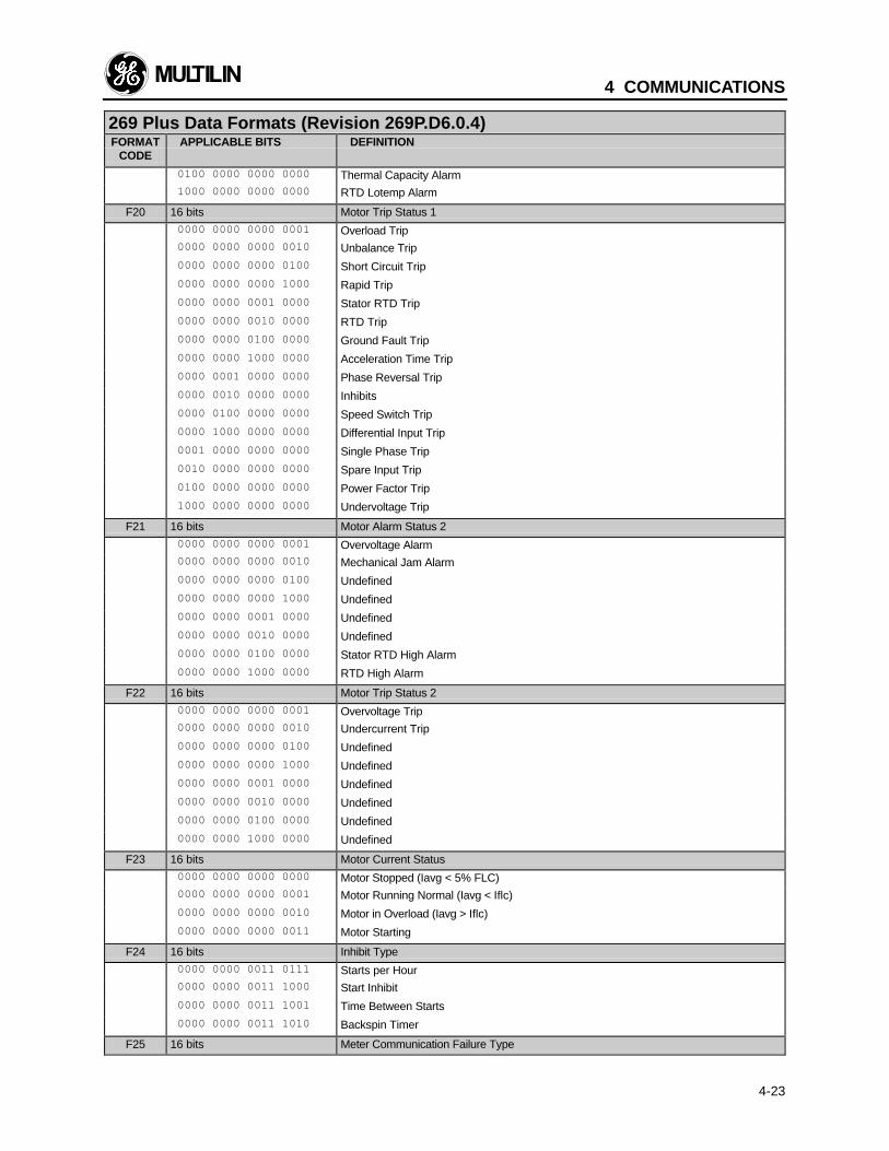
4 COMMUNICATIONS
4-23
269 Plus Data Formats (Revision 269P.D6.0.4)FORMAT APPLICABLE BITS DEFINITION
CODE
0100 0000 0000 0000 Thermal Capacity Alarm 1000 0000 0000 0000 RTD Lotemp Alarm
F20 16 bits Motor Trip Status 1
0000 0000 0000 0001 Overload Trip 0000 0000 0000 0010 Unbalance Trip
0000 0000 0000 0100 Short Circuit Trip
0000 0000 0000 1000 Rapid Trip
0000 0000 0001 0000 Stator RTD Trip
0000 0000 0010 0000 RTD Trip
0000 0000 0100 0000 Ground Fault Trip
0000 0000 1000 0000 Acceleration Time Trip
0000 0001 0000 0000 Phase Reversal Trip
0000 0010 0000 0000 Inhibits
0000 0100 0000 0000 Speed Switch Trip
0000 1000 0000 0000 Differential Input Trip
0001 0000 0000 0000 Single Phase Trip
0010 0000 0000 0000 Spare Input Trip
0100 0000 0000 0000 Power Factor Trip
1000 0000 0000 0000 Undervoltage Trip
F21 16 bits Motor Alarm Status 2
0000 0000 0000 0001 Overvoltage Alarm 0000 0000 0000 0010 Mechanical Jam Alarm
0000 0000 0000 0100 Undefined
0000 0000 0000 1000 Undefined
0000 0000 0001 0000 Undefined
0000 0000 0010 0000 Undefined
0000 0000 0100 0000 Stator RTD High Alarm
0000 0000 1000 0000 RTD High Alarm
F22 16 bits Motor Trip Status 2
0000 0000 0000 0001 Overvoltage Trip 0000 0000 0000 0010 Undercurrent Trip
0000 0000 0000 0100 Undefined
0000 0000 0000 1000 Undefined
0000 0000 0001 0000 Undefined
0000 0000 0010 0000 Undefined
0000 0000 0100 0000 Undefined
0000 0000 1000 0000 Undefined
F23 16 bits Motor Current Status
0000 0000 0000 0000 Motor Stopped (Iavg < 5% FLC) 0000 0000 0000 0001 Motor Running Normal (Iavg < Iflc)
0000 0000 0000 0010 Motor in Overload (Iavg > Iflc)
0000 0000 0000 0011 Motor Starting
F24 16 bits Inhibit Type
0000 0000 0011 0111 Starts per Hour 0000 0000 0011 1000 Start Inhibit
0000 0000 0011 1001 Time Between Starts
0000 0000 0011 1010 Backspin Timer
F25 16 bits Meter Communication Failure Type
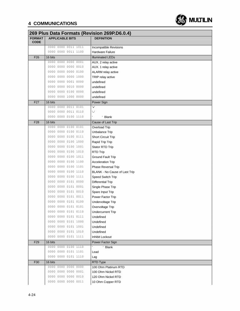
4 COMMUNICATIONS
4-24
269 Plus Data Formats (Revision 269P.D6.0.4)FORMAT APPLICABLE BITS DEFINITION
CODE
0000 0000 0011 1011 Incompatible Revisions 0000 0000 0011 1100 Hardware Failure
F26 16 bits Illuminated LEDs
0000 0000 0000 0001 AUX. 2 relay active 0000 0000 0000 0010 AUX. 1 relay active
0000 0000 0000 0100 ALARM relay active
0000 0000 0000 1000 TRIP relay active
0000 0000 0001 0000 undefined
0000 0000 0010 0000 undefined
0000 0000 0100 0000 undefined
0000 0000 1000 0000 undefined
F27 16 bits Power Sign
0000 0000 0011 0101 '+' 0000 0000 0011 0110 '–'
0000 0000 0100 1110 ‘ ‘ Blank
F28 16 bits Cause of Last Trip
0000 0000 0100 0101 Overload Trip 0000 0000 0100 0110 Unbalance Trip
0000 0000 0100 0111 Short Circuit Trip
0000 0000 0100 1000 Rapid Trip Trip
0000 0000 0100 1001 Stator RTD Trip
0000 0000 0100 1010 RTD Trip
0000 0000 0100 1011 Ground Fault Trip
0000 0000 0100 1100 Acceleration Trip
0000 0000 0100 1101 Phase Reversal Trip
0000 0000 0100 1110 BLANK - No Cause of Last Trip
0000 0000 0100 1111 Speed Switch Trip
0000 0000 0101 0000 Differential Trip
0000 0000 0101 0001 Single Phase Trip
0000 0000 0101 0010 Spare Input Trip
0000 0000 0101 0011 Power Factor Trip
0000 0000 0101 0100 Undervoltage Trip
0000 0000 0101 0101 Overvoltage Trip
0000 0000 0101 0110 Undercurrent Trip
0000 0000 0101 0111 Undefined
0000 0000 0101 1000 Undefined
0000 0000 0101 1001 Undefined
0000 0000 0101 1010 Undefined
0000 0000 0101 1111 Inhibit Lockout
F29 16 bits Power Factor Sign
0000 0000 0100 1110 ‘ ‘ Blank 0000 0000 0101 1101 Lead
0000 0000 0101 1110 Lag
F30 16 bits RTD Type
0000 0000 0000 0000 100 Ohm Platinum RTD 0000 0000 0000 0001 100 Ohm Nickel RTD
0000 0000 0000 0010 120 Ohm Nickel RTD
0000 0000 0000 0011 10 Ohm Copper RTD

4 COMMUNICATIONS
4-25
269 Plus Data Formats (Revision 269P.D6.0.4)FORMAT APPLICABLE BITS DEFINITION
CODE
F31 16 bits Serial Number Letter Code
0000 0000 0110 0001 Hardware Revision “C” 0000 0000 0110 0010 Hardware Revision “D”
0000 0000 0110 0011 Hardware Revision “E”
0000 0000 0110 0100 Hardware Revision “B”
F32 16 bits Setpoints Status Register 3
0000 0000 0000 0001 Enable U/V Trips & Alarm if Avg. Volts = 0 0000 0000 0000 0010 Enable Differential Input to Read 52b
F33 16 bits Self Test Alarm Status
0000 0000 0001 0011 Analog to Digital (A/D) Hardware Failure Alarm 0000 0000 0001 0100 RTD Hardware (H/W) Failure Alarm
0000 0000 0001 0101 RAM Memory Failure Alarm
0000 0000 0001 1000 EPROM Mismatch/Model Failure Alarm
5 TESTING
5-1
5. 1 Primary Injection Testing
Prior to relay commissioning at an installation, com-plete system operation can be verified by injecting cur-rent through the phase and ground fault CTs. To dothis a primary (high current) injection test set is re-quired.
Operation of the entire relay system, except the phaseCTs, can be checked by applying input signals to the269 relay from a secondary injection test set as de-scribed in the following sections.
"Multiamp" or "Doble" test equipment can be used todo current and timing tests.
5.2 Secondary Injection Testing
Single phase secondary injection testing can be per-formed using the test set up shown in figure 5.1. Testsshould be performed to verify correct operation of relayinput (A/D), output, memory, and RTD circuitry. 269Plus relay functions are firmware driven and thus test-ing is required only to verify correct firmware/ hardwareinteraction.
All tests described in the following sections will be ap-plicable with factory setpoints and configurations leftunchanged. Similar tests can be performed after newsetpoints have been stored in the 269 Plus relay.
5.3 Phase Current Input Functions
All phase current functions use digital current informa-tion converted from the analog phase C.T. inputs.Functions that use phase current readings are over-load, unbalance, short circuit, and rapid trip. The 269Plus must read the injected phase currents correctly inorder for these functions to operate properly. To deter-mine if the relay is reading the proper current valuesinject a phase current into the relay and view the threecurrent readings in ACTUAL VALUES mode, page 1.With factory setpoints stored in the relay the displayedcurrent should be:
displayed current = actual injected current × 100/5(phase CT ratio)
Various trip and alarm conditions can be simulated byadjusting the injected phase currents. All trip/alarmconditions using phase current readings will operate asdescribed in Section 3 providing the 269 Plus relayreads the correct phase current.
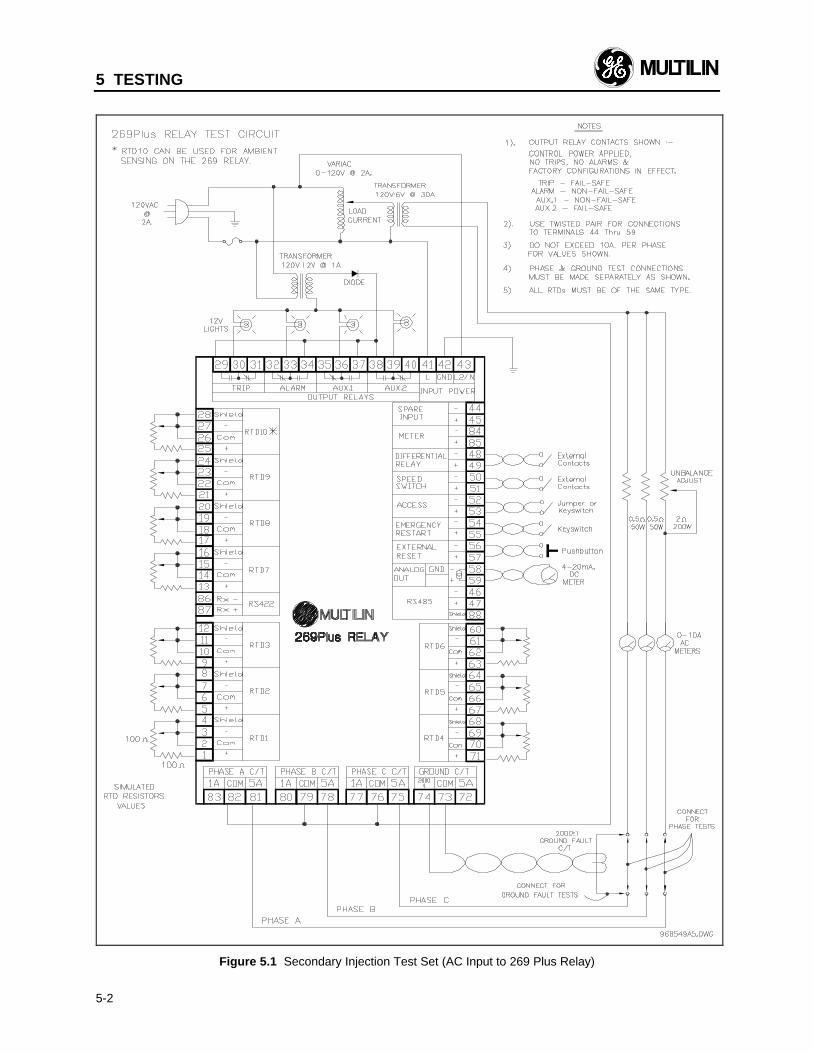
5 TESTING
5-2
Figure 5.1 Secondary Injection Test Set (AC Input to 269 Plus Relay)
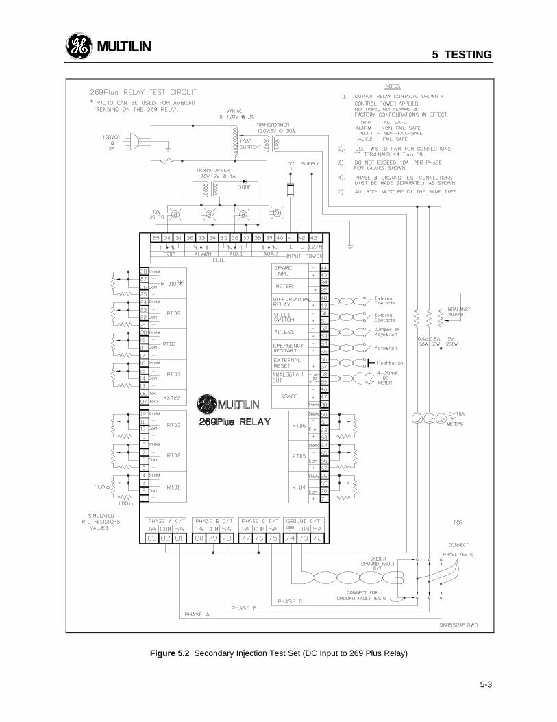
5 TESTING
5-3
Figure 5.2 Secondary Injection Test Set (DC Input to 269 Plus Relay)

5 TESTING
5-4
To simulate an overload condition turn "ACCEL.TIME=" to "off" (SETPOINTS, page 1) and inject a cur-rent of 9 Amps in all three phases. This will be read bythe relay as:
displayed current = 9 Amps x 100/5 = 180 Amps
which is two times the Full Load Current setpoint of 90Amps. The trip output relay should activate after a time of116 seconds which is the time to trip for a 200% overloadusing curve #4. This time may be less due to the chargingof thermal memory because of the presence of unbalanceor previous overloads. Thermal memory may be dis-charged to 0% by shorting together the Emergency Re-start terminals (54, 55) momentarily.
To check the displayed negative to positive sequenceunbalance ratio inject currents of 5.0 Amps, 5.0 Ampsand 3.9 Amps into the relay and examine the"UNBALANCE RATIO". The reading should be 14%.Other unbalance conditions can be checked by calcu-lating the negative to positive sequence current ratio forthe injected phase currents and comparing this to theACTUAL VALUES display.
5.4 Ground Fault Current Functions
The ground fault current function uses digital currentinformation converted from the analog ground fault C.T.input. The 269 Plus relay must read the injected groundfault current correctly in order for the ground fault func-tion to operate properly. Using factory default setpointsto test the ground fault input circuitry, pass a phasecurrent conductor through the ground fault CT windowas shown in figure 5.1. The actual injected currentshould then be the same as the "GROUND FAULT
CURRENT" display in ACTUAL VALUES mode. If theinjected current is adjusted to over 4.0 Amps for longerthan 10.0 seconds the ground fault alarm should be-come active. If over 8.0 Amps is injected for more than50 msec. a ground fault trip should occur. These testscan be performed for other C.T. ratios and setpoints.
5.5 RTD Measurement Tests
The correct operation of each of the RTD inputs can betested by simulating RTDs with potentiometers. To testa 269 Plus relay configured for use with 100 OHMplatinum RTDs, 100 OHM potentiometers and resistorscan be used. These should be connected to each RTDas shown in figure 5.1.
Table 5-1 shows RTD resistances for various tempera-tures. Individual, actual stator and bearing RTD tem-peratures can be viewed in ACTUAL VALUES mode,page 2.
To test overtemperature trip/alarm functions the simu-lated RTD potentiometers should be adjusted to corre-spond to high RTD temperatures.
Stator RTD Voting in Setpoint Values page 5 should bedefeated first. This allows for individual trip/alarm over-temperature testing.
Table 5-1 RTD Resistance vs. Temperature
TEMP°C
OHMS100 OHM Pt(DIN 43760)
OHMS120 OHM Ni
OHMS100 OHM Ni
OHMS10 OHM Cu
0102030405060708090100110120130140150160170180190200
100.00103.90107.79111.67115.54119.39123.24127.07130.89134.70 138.50 142.29 146.06 149.82 153.58 157.32 161.04 164.76 168.47 172.46 175.84
120.00127.17134.52142.06149.79157.74165.90174.25182.84191.64
200.64 209.85 219.29 228.96 238.85 248.95 259.30 269.91 280.77 291.96 303.46
100.00105.97112.10118.38124.82131.45138.25145.20152.37159.70167.20174.87182.75190.80199.04207.45216.08224.92233.97243.30252.88
9.049.429.8110.1910.5810.9711.3511.7412.1212.5112.9013.2813.6714.0614.4414.8315.2215.6116.0016.3916.78
5 TESTING
5-5
5.6 Power Failure Testing
When the AC. voltage applied to a 120VAC 269 Plusrelay decreases to below about 80 V, all relay L.E.D.sshould become illuminated. If a different supply voltageis being used (240VAC, 125VDC, 250VDC, 24VDC, or48VDC) consult the specifications section for power faillevels. All output relays will also go to their power downstates. To test the memory circuitry of the relay, removeand then re-apply control power. All stored setpointsand statistical data should be unchanged. The dis-played lock-out time after an overload trip should con-tinue to decrease even when control power is removed.
5.7 Analog Current Output
Using the factory default setpoints to test the analogcurrent output, a 4-20 mA DC. ammeter should beconnected between terminals 58 and 59. While viewingthe "HOTTEST STATOR RTD" actual value adjust theresistance of the simulated stator RTD potentiometersshown in figure 5.1. A displayed reading of 0 C shouldcorrespond to a 4 mA output. A reading of 200 Cshould correspond to an output of 20 mA. The outputshould be a linear function of temperature betweenthese extremes. Similar tests can be performed for theother output options (thermal capacity used, motor loadas a percentage of full load).
5.8 Routine Maintenance Verification
Once a relay has been properly installed, annual testingshould be performed to check correct operation of theprotection system. Many conditions can be simulatedwithout creating the actual trip/alarm conditions them-selves. This is done by changing relay setpoints tovalues which will initiate trips and alarms during normalmotor operation. Changed setpoints should be re-turned to their proper values when tests have beencompleted. The Access terminals must be shortedtogether to allow setpoint changes. The EmergencyRestart terminals should be shorted together momen-tarily 5 times before each test to ensure that the relaythermal memory is fully discharged and starts per hourcounter is fully cleared.
To test relay functions using phase current data, withthe motor running, change the "MOTOR FULL LOADCURRENT" setpoint to a value under the actual motorcurrent. Stop the motor and short the Emergency Re-start terminals together momentarily to discharge thethermal memory in the relay. The trip relay should ac-tivate after a time determined from the overload curve,amount of unbalance present, and motor RTD tem-perature. The time to trip at a given overload levelshould never be greater than the time on the overloadcurve. Current unbalance and high stator RTD tem-peratures will cause this time to be shorter (if the RTDbias and/or U/B bias functions are enabled).
Larger overloads, representing short circuits or me-chanical jams, can be simulated by changing the"MOTOR FULL LOAD CURRENT" setpoint to a valuemuch lower than the actual motor phase current.
Unbalance trip or alarm conditions can be simulated bychanging the Unbalance Trip or Alarm Level setpointsto values below the actual unbalance present at themotor terminals.
Other trip or alarm conditions using ground fault cur-rent data and RTD temperature data can be simulatedusing the procedures outlined in the previous sections.
To test the operation of the 269 Plus output relays andthe switchgear connected to them the "EXERCISE:XXXXX RELAY" setpoint in page 6 of SETPOINTSmode can be used. The motor must be stopped in or-der for this function to operate. Any or all of the outputrelays can be toggled using this setpoint.
To test the analog output current hardware the"ANALOG OUT FORCED TO: XXXXXX SCALE" set-point can be used. The output current can be forced to"ZERO", "MID", or "FULL" scale. This feature can beused to test the calibration of the 269 Plus as well asthe operation of any device through which the current isflowing. The motor must be stopped in order for thisfunction to operate.
To test the operation of devices connected to the SpareInput, Differential Input, Speed Switch Input, Accessterminals, Emergency Restart terminals, and ExternalReset terminals the "STATUS" setpoint can be used.This is in page 6 of SETPOINTS mode. This line willgive the status of each pair of terminals as either"OPEN" or "SHORT".
5.9 Dielectric Strength (Hi-Pot) Test
The 269 Plus relay is Hi-Pot tested at the factory for 1second at 2200 VAC in order to verify its dielectricstrength. See Fig 5.3 for the test procedure.
If the 269 Plus is of the Drawout version, Hi-Pot testingof wires in the switchgear is possible without the needto remove wires attached to the drawout case termi-nals. However, the 269 Plus in its cradle should bewithdrawn from the case before Hi-Pot testing starts.Failure to do so may result in internal damage to the269 Plus.

5 TESTING
5-6
Figure 5.3 Hi-Pot Testing Procedure
6 THEORY OF OPERATION
6-1
6.1 Hardware
All relay functions are controlled by an 80C32 8 bit mi-crocomputer. This I.C. contains internal RAM and tim-ers, but all firmware and display messages are storedin an external EPROM I.C. A 12 key keypad and a 2row × 24 character display are used to enter relay set-points and display all values and messages. A hard-ware block diagram is shown in figure 6.1.
The power supply uses a dual primary / triple secon-dary transformer for connection to 120/240 VAC. A24/48/125/250 VDC input switching power supply isalso available as an option. Regulated ±5 V suppliesare created for use by logic and analog I.C.s. An un-regulated +10 V supply is used to drive the RTD selec-tion relays and L.E.D. indicators, and an isolated +10 Vsupply is used on the AC input versions to drive theoutput relays and read the contact inputs. +2.5 V refer-ence voltages are derived from temperature compen-sated precision voltage reference diodes to providestable, drift-free references for the analog circuitry. Apower fail detector circuit is used to reset the relaywhenever the supply voltage goes out of the properoperational range. This hardware watchdog circuitmust be signaled regularly by a firmware generatedvoltage or else the microcomputer will be reset.
Three phase C.T.s are used to scale the incoming cur-rent signals to the 269 Plus relay. The current wave-forms are then rectified and fed through fixed burdensto produce a voltage signal of 430 mV peak/ FLC. Thissignal is then multiplexed. The multiplexed signal isbuffered and fed to an A/D converter. The digital signalis then fed to the microcomputer for analysis. A sepa-rate ground fault C.T. is provided on the 269 Plus relayto scale the input ground fault current. This currentsignal is rectified and fed through a resistive burden toconvert it to 1.25 V peak/ secondary amps rating. Thisis then fed to the same multiplexer as the phase inputsignals.
The temperature monitoring circuitry of the 269 Plusrelay consists of 10 RTD connections multiplexed byminiature relays and a 4 to 10 decoder. Mechanicalrelays are used because of their excellent isolation,transient immunity, and almost zero on-resistance. Astable current source feeds each of the RTDs in turn,and 128 readings are taken over a period of one sec-ond for each RTD. This provides for stable averagingand good 50/60 Hz noise rejection. An RTD lead com-pensation circuit subtracts the RTD lead resistance andthen the analog RTD voltage is multiplexed along withthe phase and ground fault signals. A no sensor de-tector circuit indicates when no current flows in an RTDin order to distinguish a faulty sensor from a high tem-perature reading.
The 80C32 microcomputer interfaces with an 8155HI/O port and static RAM to drive an intelligent displaymodule and provide a digital output signal for a D/A
converter. The analog output signal from the DAC isthen converted to a current and scaled to be 4-20 mA.The microcomputer also drives an 8255A I/O portwhich handles keypad inputs, L.E.D. drivers, and exter-nal switch inputs. The data lines from the 80C32 arelatched before being passed to the address lines of theEPROM and NOVRAM. NOVRAM store cycles areinitiated every time control power goes out of the rec-ommended operating range. The output relays arecontrolled by the microcomputer through optoisolatorsand are powered by a separate, isolated +10 V supply.An SN 75176 transceiver is used to provide an RS485communications interface for programmable controllersand computers for the 269 Plus.
All connections to the 269 Plus relay are made on theI/O circuit board; transient protection and filtering areprovided on all inputs.
6.2 Firmware
All mathematical, logic and control functions are per-formed on an 80C32 microcomputer by a programstored on a separate EPROM. The program executionflow is shown in the firmware block diagram of figure6.2.
Every 2 mS the system clock generates an interrupt.At this time all timers are updated, the keypad is readand debounced, and five A/D conversions are per-formed by the A/D module. These conversions are theground fault current reading, three phase current read-ings, and a single RTD, voltage reference, or power failcircuit reading. At this point the RMS values of thecurrents are calculated, and short circuit and groundfault tests are made. The EOC interrupt routine checksfor a motor start condition and if this is true the phasesequence is checked, a start timer is initiated, and thestart register is updated.
The INITIALIZE module is performed whenever therelay is powered on to ensure that the system comesup in a known state. Parts of this module are executedwhenever the relay is reset as well. The SYSTEMEXECUTIVE then causes execution to loop through aseries of modules which perform most of the relayfunctions.
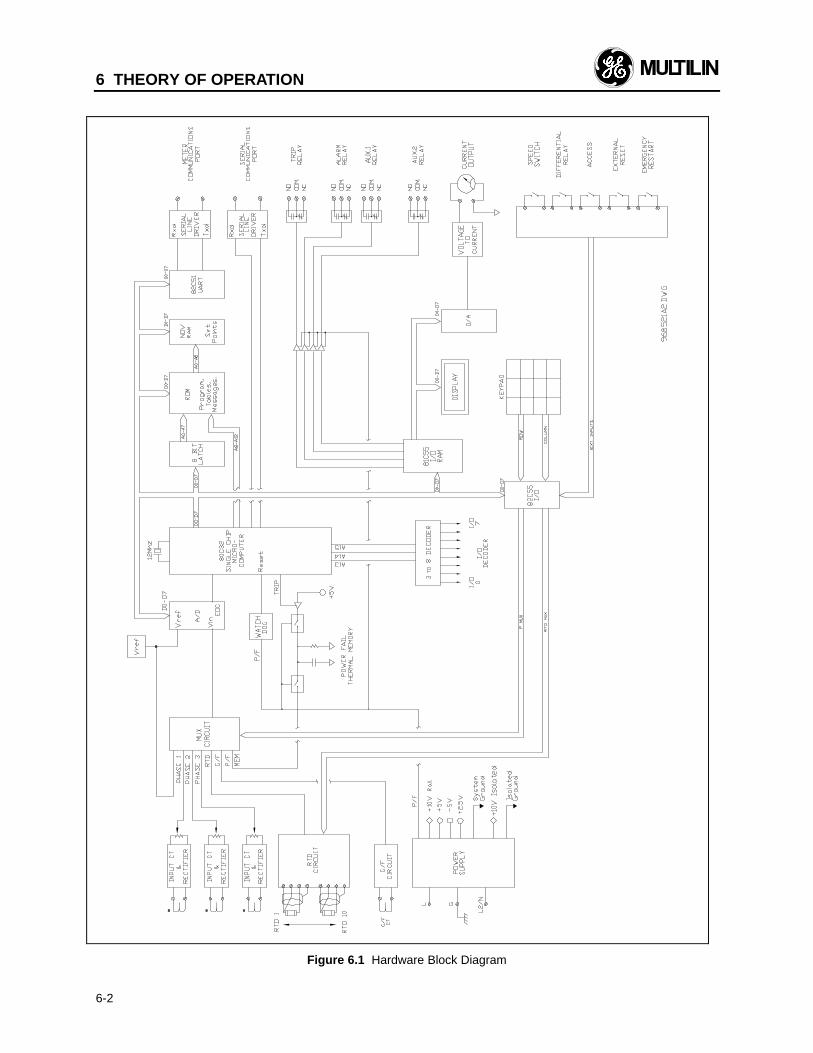
6 THEORY OF OPERATION
6-2
Figure 6.1 Hardware Block Diagram
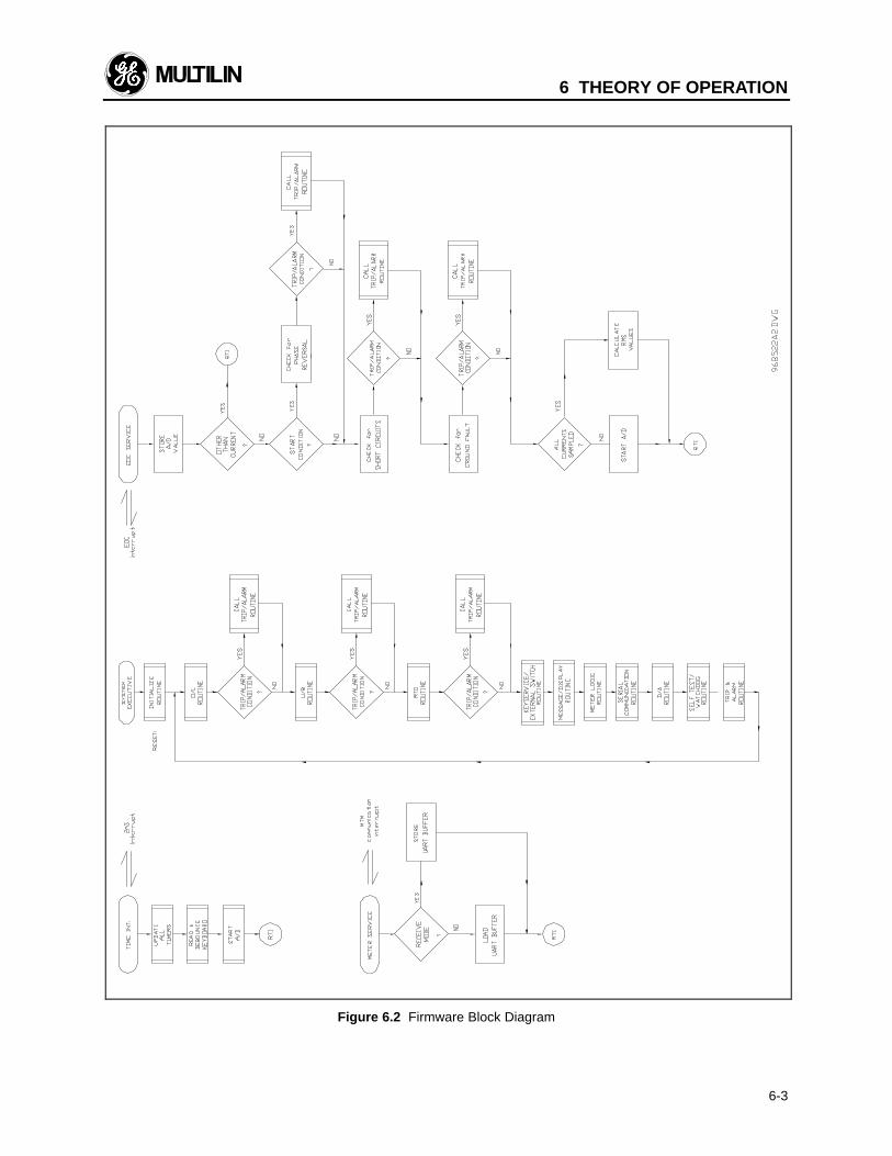
6 THEORY OF OPERATION
6-3
Figure 6.2 Firmware Block Diagram
6 THEORY OF OPERATION
6-4
The O/L module uses the positive to negative sequencecurrent ratio calculated by the U/B module, the learnedK factor, and the RMS phase currents to fill a thermalmemory register. The O/L module discharges thisregister at either a learned or preset cooling rate whenno overload is present. The average stator RTD tem-perature calculated in the RTD module is used to biasthe thermal memory. This module also compares theRMS phase current values to the Undercurrent andRapid Trip / Mechanical Jam trip and alarm levels, andstarts appropriate timers if the current levels are out ofrange.
The U/B module computes the phase current ratiosIb/Ia and Ic/Ia, and uses them in conjunction with alook-up table to determine the negative to positive se-quence current unbalance ratio In/Ip. This value iscompared to the Unbalance trip and alarm levels andappropriate timers are initiated if trip/alarm conditionsare met.
The RTD module uses the RTD voltage reading fromeach of the 10 RTD inputs and computes the averagestator RTD temperature. This is then used to bias thethermal memory. The RTD readings are compared tothe trip and alarm levels and relay activation is initiatedif conditions are met. Each RTD is read 128 times overa one second scan interval.
The KEYSERVICE/EXTERNAL SWITCH module takesin all of the data associated with the keypad and exe-cutes the function of each key. Timers for the closuretimes of the VALUE UP/DOWN, PAGE UP/DOWN, andLINE UP/DOWN keys are initiated and the display isupdated accordingly. This module also reads theEmergency Restart, External Reset, Differential Relay,and Speed Switch inputs and initiates appropriate ac-tion.
The MESSAGE module handles all of the messagelook-up functions and sends the message data to thedisplay. The displayed messages are made up of indi-vidual messages, common message strings, and vari-able data. Non-displayed control bytes are used toindicate the message type, variable data type, decimalpoint placement, and other control information.
The D/A module gives the DAC the current digital valuefor the selected option output for conversion to ananalog value. This analog voltage is then fed to a volt-age-to-current converter circuit.
The SELF-TEST module causes the 80C32 to send outregular voltage signals to indicate to the power supplywatchdog circuit that the system is operating properly.This module also performs all of the self-test featuresoutlined in section 3.23.
The TRIP/ALARM module is executed when any relaytrip or alarm setpoint has been exceeded. This modulehandles output relay activation and TRIP/ALARM mes-sage output.
Statistical data is updated whenever a statistical valuechanges. For example, the total number of motorstarts value is updated every time a motor start is de-tected.
7 APPLICATION EXAMPLES
7-1
7.1 269 Plus Relay Powered from Oneof Motor Phase Inputs
If a 269 Plus relay is powered from one of the threemotor phase inputs, a single phase condition couldcause control power to be removed from the relay. Inorder to ensure that the motor is taken off-line if thiscondition arises, the 269 Plus output relay (eg. TRIP,AUX. 1) used to trip the motor must change state whencontrol power is removed from the 269 Plus. This isaccomplished by making this output relay fail-safe.Factory defaults are:
TRIP: Fail-SafeALARM: Non-fail-safeAUX. 1: Non-fail-safeAUX. 2: Fail-safe
These can be changed using the RELAY FAILSAFECODE in page 5 of SETPOINTS mode.
7.2 Loss of Control Power Due to ShortCircuit or Ground Fault
If the input voltage (terminals 41-43) to a 269 Plus re-lay drops below the low end specification (80 VAC on120 VAC units), the 269 Plus output relays will return totheir power down states. If the input voltage drops dueto a short circuit or ground fault on a motor, the 269Plus relay protecting the motor may or may not be ableto trip out the motor. For example, if a 120 VAC 269Plus relay is set to trip after 0.5 seconds of an 8.0×FLC short circuit current, the input voltage must re-main above 90 VAC for at least 0.5 seconds after theshort circuit has occurred or else the 269 Plus relay willnot be able to trip. As explained in section 6.1 above,in order to trip the motor when control power for the269 Plus is lost, the 269 Plus output relay used to tripthe motor must be configured as fail-safe.
7.3 Example Using FLC Thermal Ca-pacity Reduction Setpoint
The purpose of the FLC Thermal Capacity ReductionSetpoint is to accurately reflect the reduction of thermalcapacity available (increase the thermal capacity used)in a motor that is running normally (100% of FLC orless). This setpoint allows the user to define theamount of thermal capacity used by their motor runningat 1 FLC. A motor that is running at 10% of FLC willobviously use less thermal capacity than a motor at100% FLC.
For example, if the FLC Thermal Capacity ReductionSetpoint is set at 30%, then with the motor running at 1FLC, the thermal capacity used will settle at 30%. Us-ing the same example, with the motor running at 50%
FLC, the thermal capacity used will settle at 15% (50%of 30%). A practical example of implementation of thissetpoint to coordinate hot/cold damage curves is illus-trated below.
Assume the motor manufacturer has provided the fol-lowing information:
1. Maximum permissible locked rotor time (hot motor) =15.4 seconds.
2. Maximum permissible locked rotor time (cold motor)= 22 seconds.
3. Recommended thermal limit curves are as shown inFigure 7.1.
Note: Hot motor is defined as a motor that has beenrunning at 1 FLC, but not in an overload, for a period oftime such that the temperature remains constant (typi-cal 90 °C). Cold motor is defined as a motor which hasbeen stopped for a period of time such that the tem-perature remains constant (ambient temperature isdefined by NEMA standard as 40 °C).
From the formula:
TCR = 1-(Hot Motor Stall Time)(Cold Motor Stall Time)
× 100
TCR = [1 - (15.4/22)] × 100Thermal Capacity Reduction = 30%
The hot motor locked rotor time is 30% less than thecold motor locked rotor time. Therefore the FLC Ther-mal Capacity Reduction Setpoint should be set to 30%.The overload curve selected should lie below the coldthermal damage curve. Once the motor has been run-ning for a period of time at 1 FLC the thermal capacityused will remain constant at 30%. The time to trip atany overload value will correspondingly be 30% less.
Once a motor comes out of an overload condition, thethermal capacity used will discharge at the correct ratewhich is exponential and settle at a value defined by theFLC Thermal Capacity Reduction Setpoint and the pre-sent current value. Using the example above if themotor came out of an overload and the present currentvalue was 50% FLC the thermal capacity used woulddischarge to a value of 15% (50% of 30%).
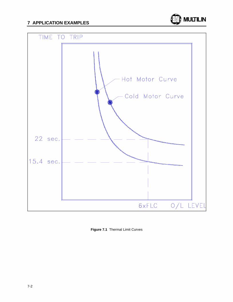
7 APPLICATION EXAMPLES
7-2
Figure 7.1 Thermal Limit Curves
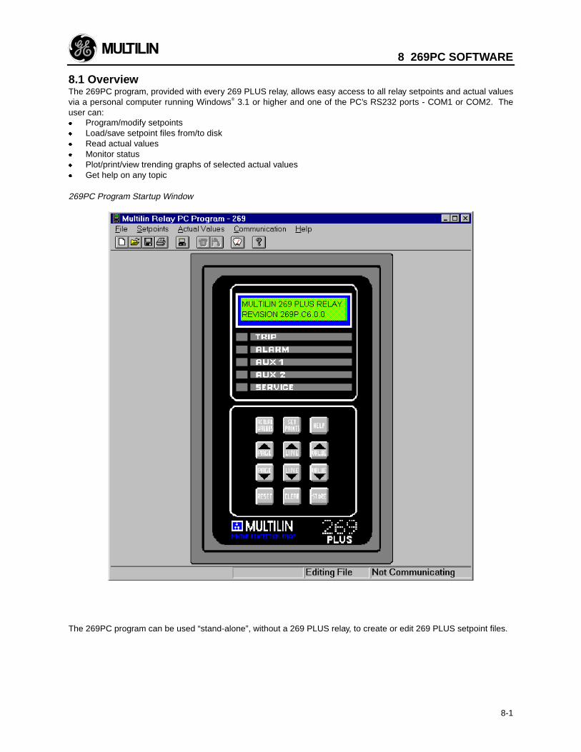
8 269PC SOFTWARE
8-1
8.1 OverviewThe 269PC program, provided with every 269 PLUS relay, allows easy access to all relay setpoints and actual valuesvia a personal computer running Windows® 3.1 or higher and one of the PC’s RS232 ports - COM1 or COM2. Theuser can:x Program/modify setpointsx Load/save setpoint files from/to diskx Read actual valuesx Monitor statusx Plot/print/view trending graphs of selected actual valuesx Get help on any topic
269PC Program Startup Window
The 269PC program can be used “stand-alone”, without a 269 PLUS relay, to create or edit 269 PLUS setpoint files.

8 269PC SOFTWARE
8-2
8.2 Hardware and Software RequirementsThe configuration listed is for both a minimum configured and an optimal configured system. Running on a minimumconfiguration causes the performance of the PC program to slow down.
Processor: minimum 486, Pentium recommended
Memory: minimum 4 Mb, 16 Mb recommended, minimum 540 K of conventional memory
Hard Drive: 20 Mb free space required before installation of PC program.
WINDOWS 3.1/3.11 CONSIDERATIONS
x Installation of SHARE.EXE required. x Do not run other applications (spreadsheet or word processor) before running the PC program to eliminate any
problems because of low memory.
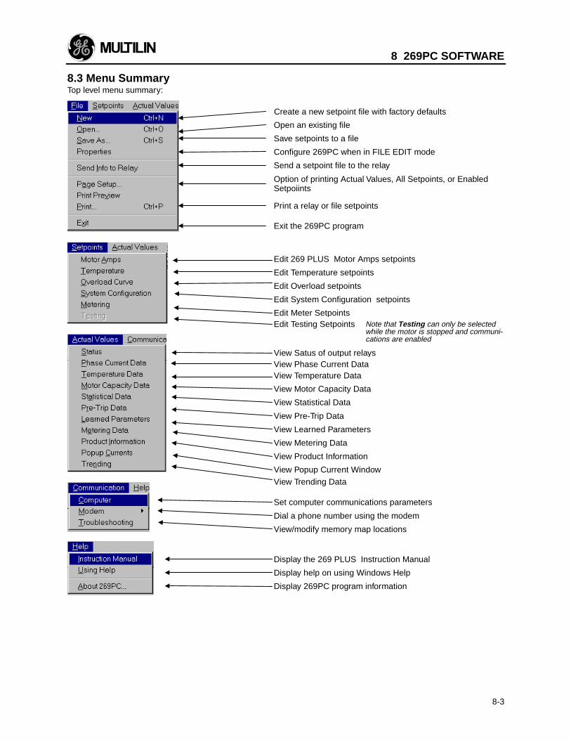
8 269PC SOFTWARE
8-3
8.3 Menu SummaryTop level menu summary:
Create a new setpoint file with factory defaults
Open an existing file
Save setpoints to a file
Send a setpoint file to the relay
Configure 269PC when in FILE EDIT mode
Print a relay or file setpoints
Exit the 269PC program
Edit 269 PLUS Motor Amps setpoints
Edit Temperature setpoints
Edit Overload setpoints
Edit System Configuration setpoints
Edit Meter Setpoints
View Satus of output relaysView Phase Current DataView Temperature Data
View Motor Capacity Data
View Statistical Data
View Pre-Trip Data
Set computer communications parameters
View/modify memory map locations
Display the 269 PLUS Instruction Manual
Display help on using Windows Help
Display 269PC program information
Dial a phone number using the modem
View Learned Parameters
View Metering Data
View Product Information
View Popup Current WindowView Trending Data
Edit Testing Setpoints Note that Testing can only be selectedwhile the motor is stopped and communi-cations are enabled
Option of printing Actual Values, All Setpoints, or EnabledSetpoiints
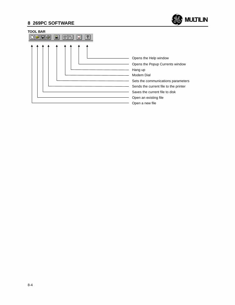
8 269PC SOFTWARE
8-4
TOOL BAR
Opens the Help window
Sends the current file to the printer
Sets the communications parameters
Saves the current file to disk
Open an existing file
Open a new file
Opens the Popup Currents window
Hang up
Modem Dial
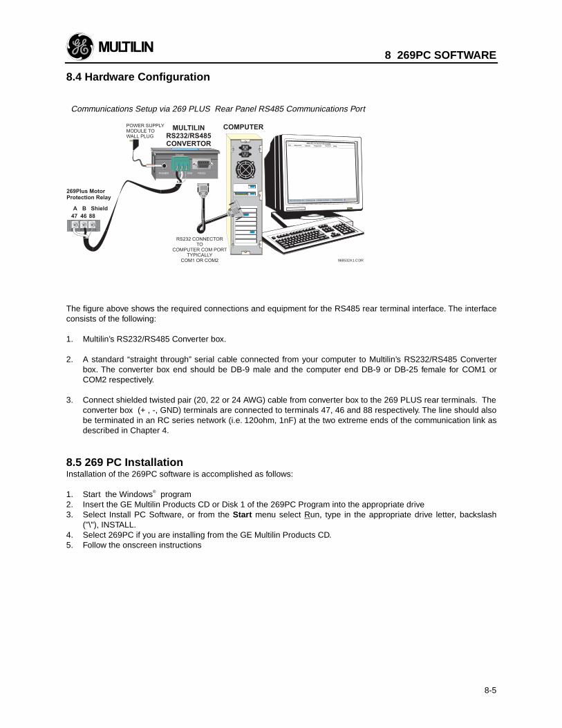
8 269PC SOFTWARE
8-5
8.4 Hardware Configuration
Communications Setup via 269 PLUS Rear Panel RS485 Communications Port
968532A1.CDR
The figure above shows the required connections and equipment for the RS485 rear terminal interface. The interfaceconsists of the following:
1. Multilin’s RS232/RS485 Converter box. 2. A standard “straight through” serial cable connected from your computer to Multilin’s RS232/RS485 Converter
box. The converter box end should be DB-9 male and the computer end DB-9 or DB-25 female for COM1 orCOM2 respectively.
3. Connect shielded twisted pair (20, 22 or 24 AWG) cable from converter box to the 269 PLUS rear terminals. The
converter box (+ , -, GND) terminals are connected to terminals 47, 46 and 88 respectively. The line should alsobe terminated in an RC series network (i.e. 120ohm, 1nF) at the two extreme ends of the communication link asdescribed in Chapter 4.
8.5 269 PC InstallationInstallation of the 269PC software is accomplished as follows:
1. Start the Windows® program2. Insert the GE Multilin Products CD or Disk 1 of the 269PC Program into the appropriate drive3. Select Install PC Software, or from the Start menu select Run, type in the appropriate drive letter, backslash
("\"), INSTALL.4. Select 269PC if you are installing from the GE Multilin Products CD.5. Follow the onscreen instructions
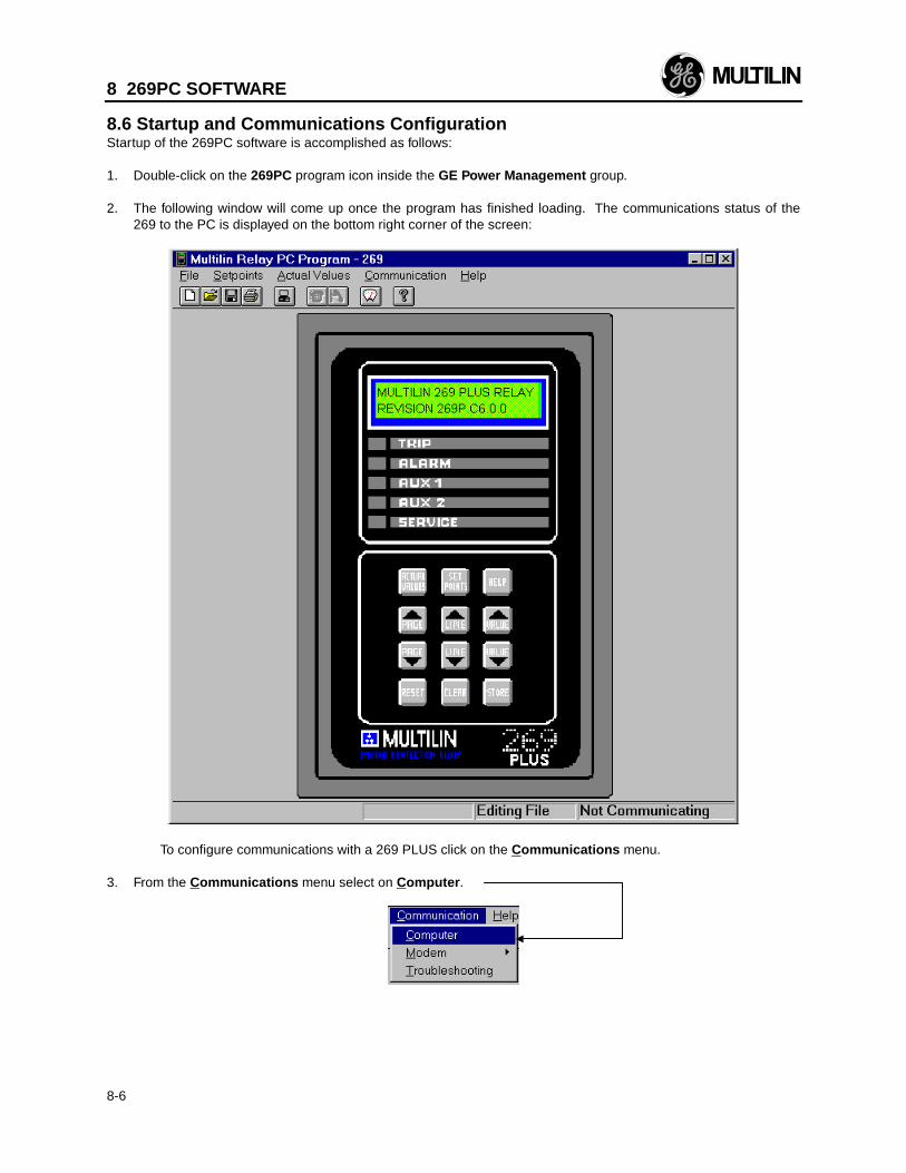
8 269PC SOFTWARE
8-6
8.6 Startup and Communications ConfigurationStartup of the 269PC software is accomplished as follows:
1. Double-click on the 269PC program icon inside the GE Power Management group.
2. The following window will come up once the program has finished loading. The communications status of the269 to the PC is displayed on the bottom right corner of the screen:
To configure communications with a 269 PLUS click on the Communications menu.
3. From the Communications menu select on Computer .
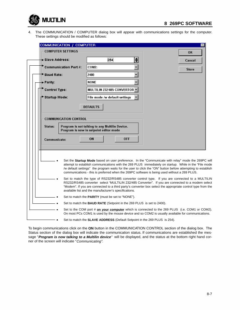
8 269PC SOFTWARE
8-7
4. The COMMUNICATION / COMPUTER dialog box will appear with communications settings for the computer.These settings should be modified as follows:
x Set the Startup Mode based on user preference. In the “Communicate with relay” mode the 269PC willattempt to establish communications with the 269 PLUS immediately on startup. While in the “File mode/w default settings” the program waits for the user to click the “ON” button before attempting to establishcommunications - this is preferred when the 269PC software is being used without a 269 PLUS.
x Set to match the type of RS232/RS485 converter control type. If you are connected to a MULTILIN
RS232/RS485 converter select “MULTILIN 232/485 Converter”. If you are connected to a modem select“Modem”. If you are connected to a third party’s converter box select the appropriate control type from theavailable list and the manufacturer’s specifications.
x Set to match the PARITY (must be set to “NONE”). x Set to match the BAUD RATE (Setpoint in the 269 PLUS is set to 2400). x Set to the COM port # on your computer which is connected to the 269 PLUS (i.e. COM1 or COM2).
On most PCs COM1 is used by the mouse device and so COM2 is usually available for communications. x Set to match the SLAVE ADDRESS (Default Setpoint in the 269 PLUS is 254).
To begin communications click on the ON button in the COMMUNICATION CONTROL section of the dialog box. TheStatus section of the dialog box will indicate the communication status. If communications are established the mes-sage “Program is now talking to a Multilin device ” will be displayed, and the status at the bottom right hand cor-ner of the screen will indicate “Communicating”.
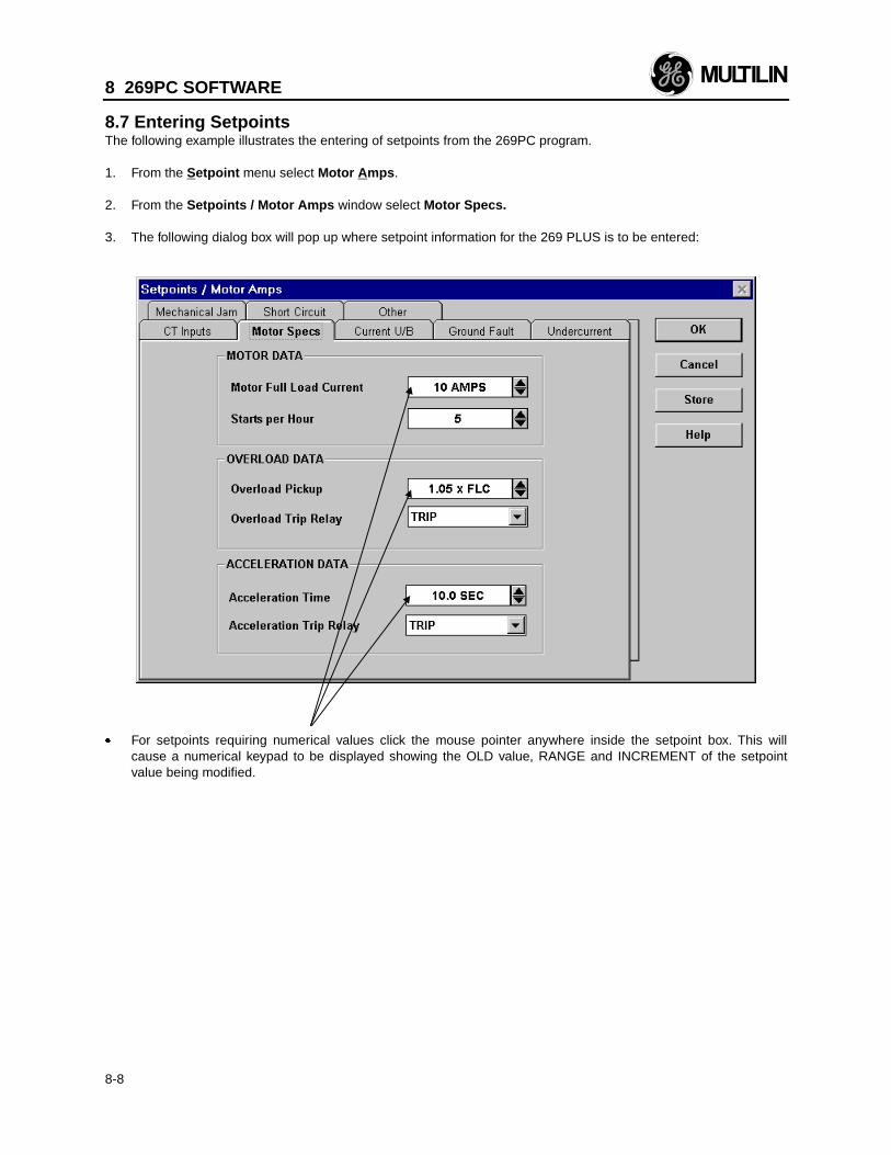
8 269PC SOFTWARE
8-8
8.7 Entering SetpointsThe following example illustrates the entering of setpoints from the 269PC program.
1. From the Setpoint menu select Motor A mps . 2. From the Setpoints / Motor Amps window select Motor Specs. 3. The following dialog box will pop up where setpoint information for the 269 PLUS is to be entered:
x For setpoints requiring numerical values click the mouse pointer anywhere inside the setpoint box. This willcause a numerical keypad to be displayed showing the OLD value, RANGE and INCREMENT of the setpointvalue being modified.
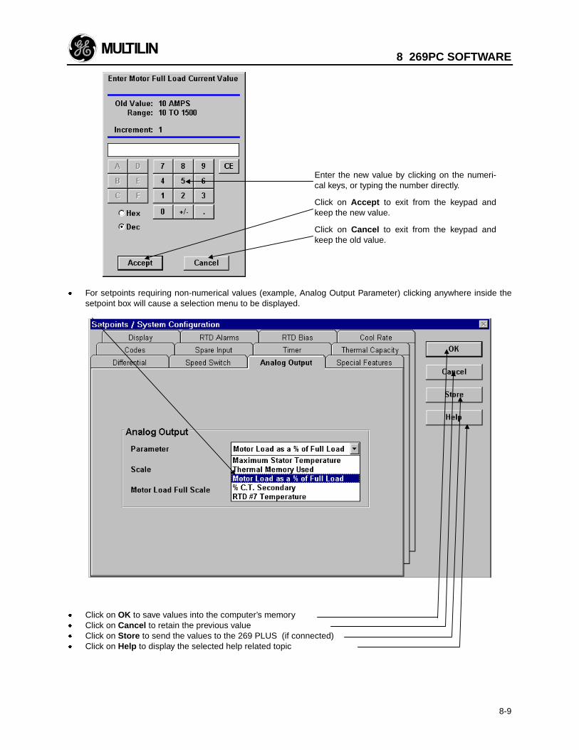
8 269PC SOFTWARE
8-9
x For setpoints requiring non-numerical values (example, Analog Output Parameter) clicking anywhere inside thesetpoint box will cause a selection menu to be displayed.
x Click on OK to save values into the computer’s memoryx Click on Cancel to retain the previous valuex Click on Store to send the values to the 269 PLUS (if connected)x Click on Help to display the selected help related topic
Enter the new value by clicking on the numeri-cal keys, or typing the number directly.
Click on Accept to exit from the keypad andkeep the new value.
Click on Cancel to exit from the keypad andkeep the old value.
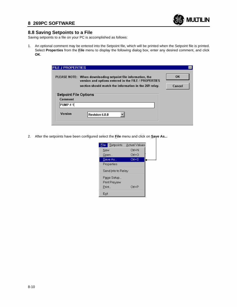
8 269PC SOFTWARE
8-10
8.8 Saving Setpoints to a FileSaving setpoints to a file on your PC is accomplished as follows:
1. An optional comment may be entered into the Setpoint file, which will be printed when the Setpoint file is printed.Select Properties from the File menu to display the following dialog box, enter any desired comment, and clickOK.
2. After the setpoints have been configured select the File menu and click on Save As.. .
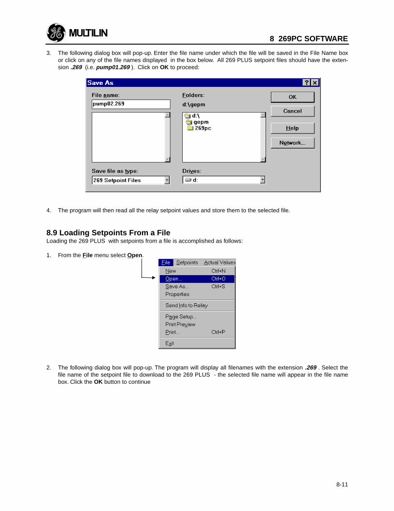
8 269PC SOFTWARE
8-11
3. The following dialog box will pop-up. Enter the file name under which the file will be saved in the File Name boxor click on any of the file names displayed in the box below. All 269 PLUS setpoint files should have the exten-sion .269 (i.e. pump01.269 ). Click on OK to proceed:
4. The program will then read all the relay setpoint values and store them to the selected file. 8.9 Loading Setpoints From a FileLoading the 269 PLUS with setpoints from a file is accomplished as follows:
1. From the File menu select Open .
2. The following dialog box will pop-up. The program will display all filenames with the extension .269 . Select thefile name of the setpoint file to download to the 269 PLUS - the selected file name will appear in the file namebox. Click the OK button to continue
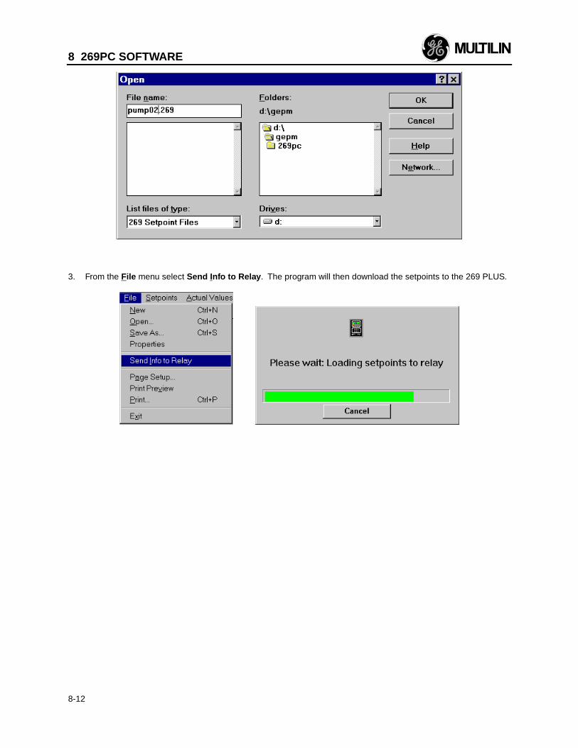
8 269PC SOFTWARE
8-12
3. From the File menu select Send Info to Relay . The program will then download the setpoints to the 269 PLUS.
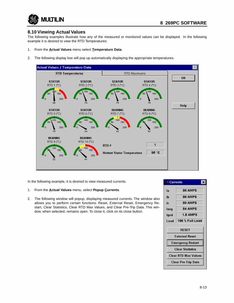
8 269PC SOFTWARE
8-13
8.10 Viewing Actual ValuesThe following examples illustrate how any of the measured or monitored values can be displayed. In the followingexample it is desired to view the RTD Temperatures:
1. From the Actual Values menu select Temperature Data . 2. The following display box will pop up automatically displaying the appropriate temperatures.
In the following example, it is desired to view measured currents.
1. From the Actual Values menu, select Popup C urrents .
2. The following window will popup, displaying measured currents. The window alsoallows you to perform certain functions: Reset, External Reset, Emergency Re-start, Clear Statistics, Clear RTD Max Values, and Clear Pre-Trip Data. This win-dow, when selected, remains open. To close it, click on its close button.
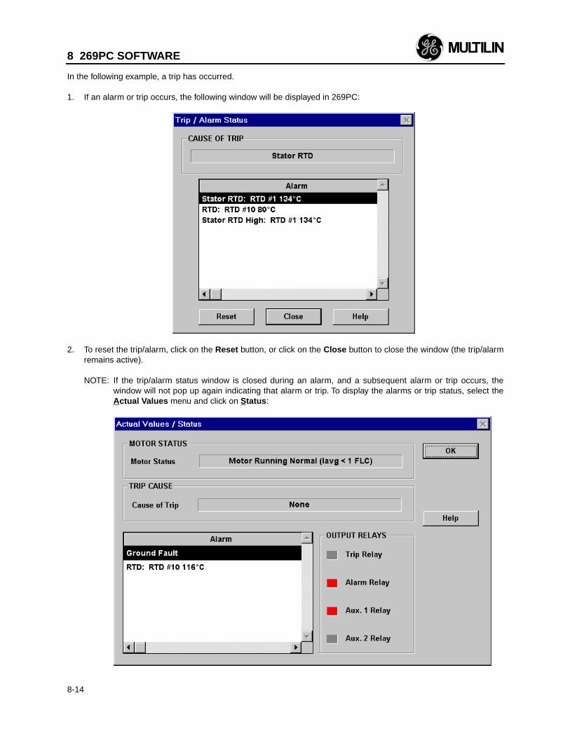
8 269PC SOFTWARE
8-14
In the following example, a trip has occurred.
1. If an alarm or trip occurs, the following window will be displayed in 269PC:
2. To reset the trip/alarm, click on the Reset button, or click on the Close button to close the window (the trip/alarm
remains active).
NOTE: If the trip/alarm status window is closed during an alarm, and a subsequent alarm or trip occurs, thewindow will not pop up again indicating that alarm or trip. To display the alarms or trip status, select theActual Values menu and click on Status :
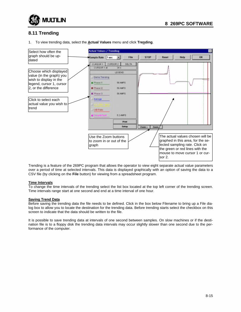
8 269PC SOFTWARE
8-15
8.11 Trending
1. To view trending data, select the Actual Values menu and click Trending.
Trending is a feature of the 269PC program that allows the operator to view eight separate actual value parametersover a period of time at selected intervals. This data is displayed graphically with an option of saving the data to aCSV file (by clicking on the File button) for viewing from a spreadsheet program.
Time IntervalsTo change the time intervals of the trending select the list box located at the top left corner of the trending screen.Time intervals range start at one second and end at a time interval of one hour.
Saving Trend DataBefore saving the trending data the file needs to be defined. Click in the box below Filename to bring up a File dia-log box to allow you to locate the destination for the trending data. Before trending starts select the checkbox on thisscreen to indicate that the data should be written to the file.
It is possible to save trending data at intervals of one second between samples. On slow machines or if the desti-nation file is to a floppy disk the trending data intervals may occur slightly slower than one second due to the per-formance of the computer.
Click to select eachactual value you wish totrend
Choose which displayedvalue (in the graph) youwish to display in thelegend, cursor 1, cursor2, or the difference
The actual values chosen will begraphed in this area, for the se-lected sampling rate. Click onthe green or red lines with themouse to move cursor 1 or cur-sor 2.
Select how often thegraph should be up-dated
Use the Zoom buttonsto zoom in or out of thegraph
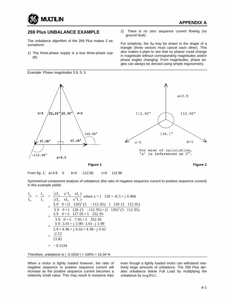
APPENDIX A
A-1
269 Plus UNBALANCE EXAMPLE
The unbalance algorithm of the 269 Plus makes 2 as-sumptions:
1) The three-phase supply is a true three-phase sup-ply.
2) There is no zero sequence current flowing (noground fault).
For simplicity, the 3φ may be drawn in the shape of atriangle (three vectors must cancel each other). Thisalso makes it plain to see that no phasor could changein magnitude without corresponding magnitudes and/orphase angles changing. From magnitudes, phase an-gles can always be derived using simple trigonometry.
Example. Phase magnitudes 3.9, 5, 5
Figure 1 Figure 2
From fig. 1: a=3.9 ∠ 0 b=5 ∠ -112.95 c=5 ∠ 112.95
Symmetrical component analysis of unbalance (the ratio of negative sequence current to positive sequence current)in this example yields:
I
I=
I
I=
(I x I xI )
(I xI x I ) where x = 1 120 = -0.5 + j 0.866
3.9 0 + (1 120)
3.9 0 +1 120 (5 -112.95) + (1 120)
3.9 0 + 5 127.05 + 5 232.95
3.9 0 + 5 7.05 + 5 352.95
3.9 - 3.01+ j 3.99 - 3.01- j 3
n
P
2
1
13 a
2b c
13 a b
2c
2
2
+ ++ +
∠
=∠ ∠ ∠ − + ∠ ∠∠ ∠ ∠ ∠ ∠
=∠ ∠ ∠∠ ∠ ∠
=
( . ) ( . )
( . )
5 112 95 1 120 5 112 95
5 112 95
.99
3.9 + 4.96 + j 0.61+ 4.96 - j 0.61
-2.12
13.82
=
= − 0 1534.
Therefore, unbalance is | -0.1534 | × 100% = 15.34 %
When a motor is lightly loaded however, the ratio ofnegative sequence to positive sequence current willincrease as the positive sequence current becomes arelatively small value. This may result in nuisance trips
even though a lightly loaded motor can withstand rela-tively large amounts of unbalance. The 269 Plus der-ates unbalance below Full Load by multiplying theunbalance by Iavg/IFLC.
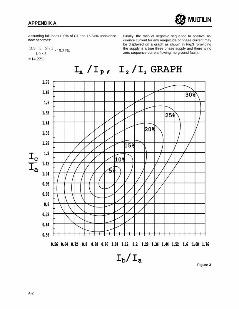
APPENDIX A
A-2
Assuming full load=100% of CT, the 15.34% unbalancenow becomes:
( . ) /.
. %
. %
3 9 5 5 31 0 5
15 34
14 22
+ +×
×
=
Finally, the ratio of negative sequence to positive se-quence current for any magnitude of phase current maybe displayed on a graph as shown in Fig.3 (providingthe supply is a true three phase supply and there is nozero sequence current flowing, no ground fault).
Figure 3
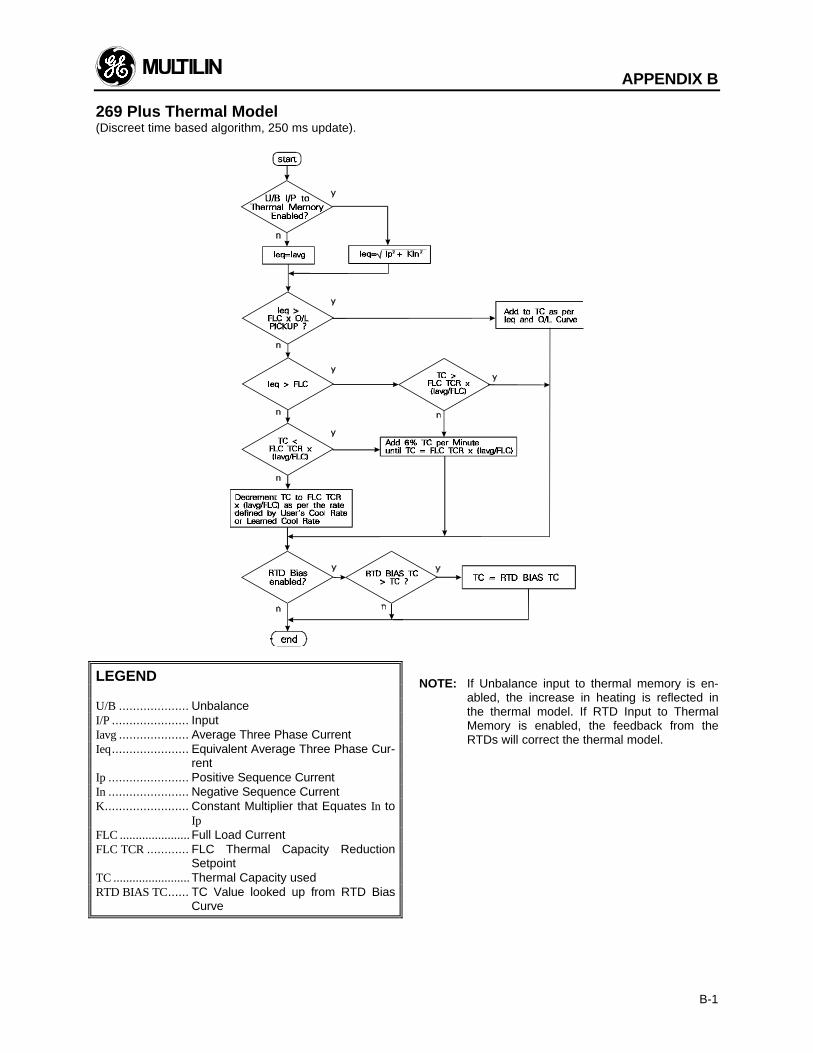
APPENDIX B
B-1
269 Plus Thermal Model(Discreet time based algorithm, 250 ms update).
LEGEND
U/B .................... UnbalanceI/P ...................... InputIavg .................... Average Three Phase CurrentIeq...................... Equivalent Average Three Phase Cur-
rentIp ....................... Positive Sequence CurrentIn ....................... Negative Sequence CurrentK........................ Constant Multiplier that Equates In to
IpFLC ...................... Full Load CurrentFLC TCR ............ FLC Thermal Capacity Reduction
SetpointTC ........................ Thermal Capacity usedRTD BIAS TC...... TC Value looked up from RTD Bias
Curve
NOTE: If Unbalance input to thermal memory is en-abled, the increase in heating is reflected inthe thermal model. If RTD Input to ThermalMemory is enabled, the feedback from theRTDs will correct the thermal model.
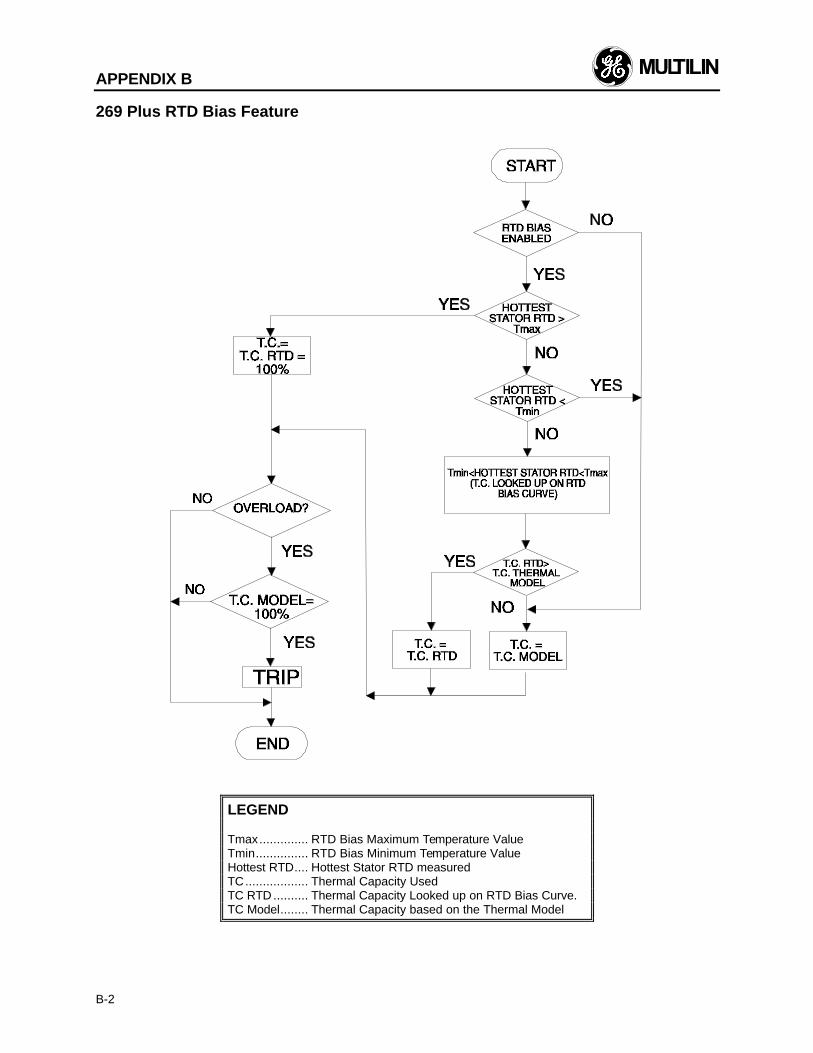
APPENDIX B
B-2
269 Plus RTD Bias Feature
LEGEND
Tmax.............. RTD Bias Maximum Temperature ValueTmin............... RTD Bias Minimum Temperature ValueHottest RTD.... Hottest Stator RTD measuredTC.................. Thermal Capacity UsedTC RTD .......... Thermal Capacity Looked up on RTD Bias Curve.TC Model........ Thermal Capacity based on the Thermal Model
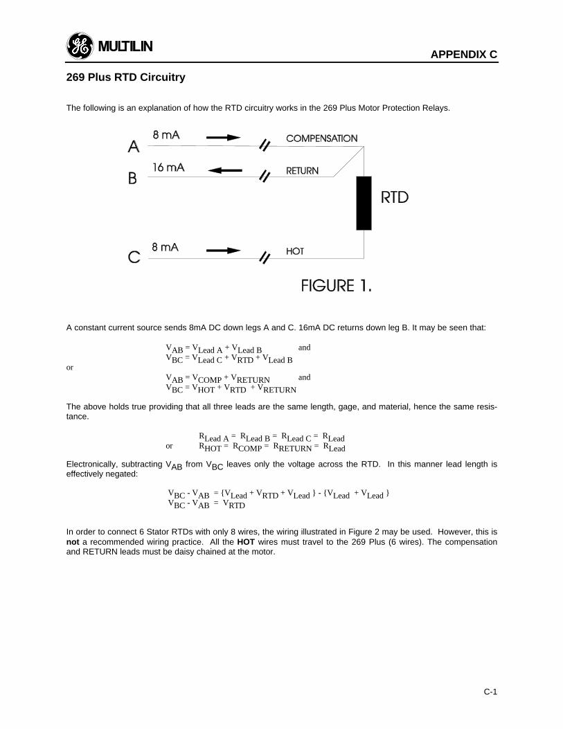
APPENDIX C
C-1
269 Plus RTD Circuitry
The following is an explanation of how the RTD circuitry works in the 269 Plus Motor Protection Relays.
A constant current source sends 8mA DC down legs A and C. 16mA DC returns down leg B. It may be seen that:
VAB = VLead A + VLead B andVBC = VLead C + VRTD + VLead B
orVAB = VCOMP + VRETURN andVBC = VHOT + VRTD + VRETURN
The above holds true providing that all three leads are the same length, gage, and material, hence the same resis-tance.
⇒ RLead A = RLead B = RLead C = RLeador RHOT = RCOMP = RRETURN = RLead
Electronically, subtracting VAB from VBC leaves only the voltage across the RTD. In this manner lead length iseffectively negated:
VBC - VAB = VLead + VRTD + VLead - VLead + VLead VBC - VAB = VRTD
In order to connect 6 Stator RTDs with only 8 wires, the wiring illustrated in Figure 2 may be used. However, this isnot a recommended wiring practice. All the HOT wires must travel to the 269 Plus (6 wires). The compensationand RETURN leads must be daisy chained at the motor.
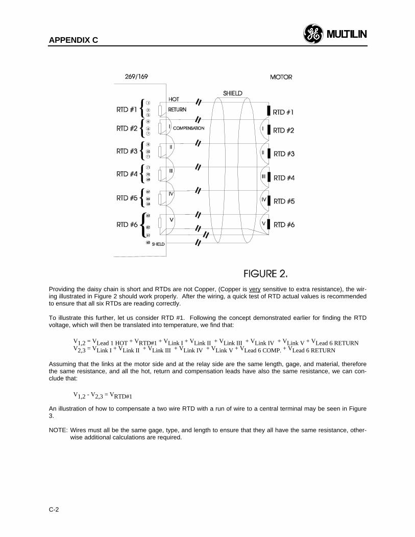
APPENDIX C
C-2
Providing the daisy chain is short and RTDs are not Copper, (Copper is very sensitive to extra resistance), the wir-ing illustrated in Figure 2 should work properly. After the wiring, a quick test of RTD actual values is recommendedto ensure that all six RTDs are reading correctly.
To illustrate this further, let us consider RTD #1. Following the concept demonstrated earlier for finding the RTDvoltage, which will then be translated into temperature, we find that:
V1,2 = VLead 1 HOT + VRTD#1 + VLink I + VLink II + VLink III + VLink IV + VLink V + VLead 6 RETURNV2,3 = VLink I + VLink II + VLink III + VLink IV + VLink V + VLead 6 COMP. + VLead 6 RETURN
Assuming that the links at the motor side and at the relay side are the same length, gage, and material, thereforethe same resistance, and all the hot, return and compensation leads have also the same resistance, we can con-clude that:
V1,2 - V2,3 = VRTD#1
An illustration of how to compensate a two wire RTD with a run of wire to a central terminal may be seen in Figure3.
NOTE: Wires must all be the same gage, type, and length to ensure that they all have the same resistance, other-wise additional calculations are required.
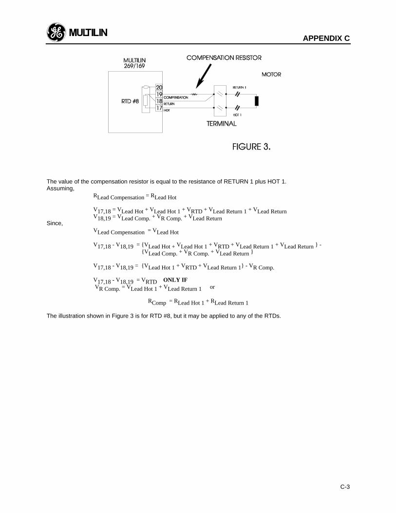
APPENDIX C
C-3
The value of the compensation resistor is equal to the resistance of RETURN 1 plus HOT 1.Assuming,
RLead Compensation = RLead Hot
V17,18 = VLead Hot + VLead Hot 1 + VRTD + VLead Return 1 + VLead ReturnV18,19 = VLead Comp. + VR Comp. + VLead Return
Since,VLead Compensation = VLead Hot
⇒ V17,18 - V18,19 = VLead Hot + VLead Hot 1 + VRTD + VLead Return 1 + VLead Return - VLead Comp. + VR Comp. + VLead Return
V17,18 - V18,19 = VLead Hot 1 + VRTD + VLead Return 1 - VR Comp.
⇒ V17,18 - V18,19 = VRTD ONLY IF VR Comp. = VLead Hot 1 + VLead Return 1 or
RComp = RLead Hot 1 + RLead Return 1
The illustration shown in Figure 3 is for RTD #8, but it may be applied to any of the RTDs.
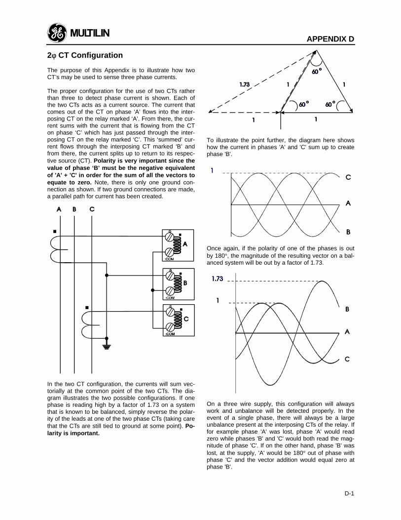
APPENDIX D
D-1
2φφ CT Configuration
The purpose of this Appendix is to illustrate how twoCT’s may be used to sense three phase currents.
The proper configuration for the use of two CTs ratherthan three to detect phase current is shown. Each ofthe two CTs acts as a current source. The current thatcomes out of the CT on phase ‘A’ flows into the inter-posing CT on the relay marked ‘A’. From there, the cur-rent sums with the current that is flowing from the CTon phase ‘C’ which has just passed through the inter-posing CT on the relay marked ‘C’. This ‘summed’ cur-rent flows through the interposing CT marked ‘B’ andfrom there, the current splits up to return to its respec-tive source (CT). Polarity is very important since thevalue of phase ‘B’ must be the negative equivalentof 'A' + 'C' in order for the sum of all the vectors toequate to zero. Note, there is only one ground con-nection as shown. If two ground connections are made,a parallel path for current has been created.
In the two CT configuration, the currents will sum vec-torially at the common point of the two CTs. The dia-gram illustrates the two possible configurations. If onephase is reading high by a factor of 1.73 on a systemthat is known to be balanced, simply reverse the polar-ity of the leads at one of the two phase CTs (taking carethat the CTs are still tied to ground at some point). Po-larity is important.
To illustrate the point further, the diagram here showshow the current in phases 'A' and 'C' sum up to createphase 'B'.
Once again, if the polarity of one of the phases is outby 180°, the magnitude of the resulting vector on a bal-anced system will be out by a factor of 1.73.
On a three wire supply, this configuration will alwayswork and unbalance will be detected properly. In theevent of a single phase, there will always be a largeunbalance present at the interposing CTs of the relay. Iffor example phase 'A' was lost, phase 'A' would readzero while phases 'B' and 'C' would both read the mag-nitude of phase 'C'. If on the other hand, phase 'B' waslost, at the supply, 'A' would be 180° out of phase withphase 'C' and the vector addition would equal zero atphase 'B'.
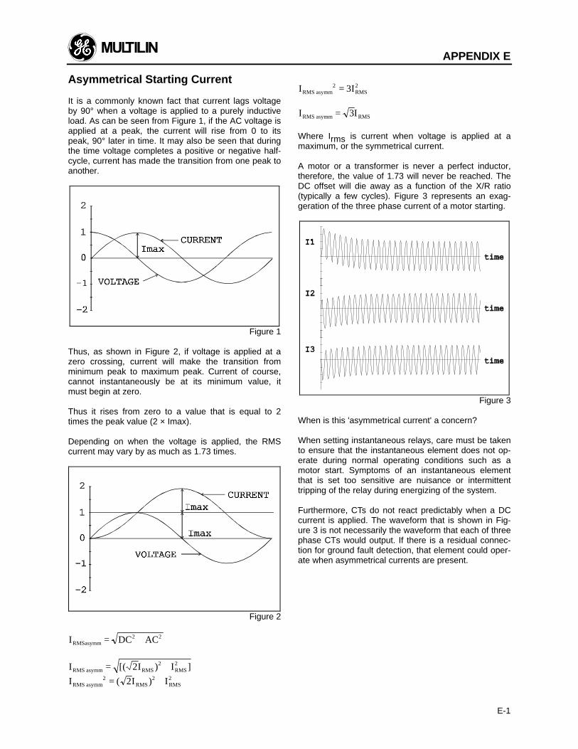
APPENDIX E
E-1
Asymmetrical Starting Current
It is a commonly known fact that current lags voltageby 90° when a voltage is applied to a purely inductiveload. As can be seen from Figure 1, if the AC voltage isapplied at a peak, the current will rise from 0 to itspeak, 90° later in time. It may also be seen that duringthe time voltage completes a positive or negative half-cycle, current has made the transition from one peak toanother.
Figure 1
Thus, as shown in Figure 2, if voltage is applied at azero crossing, current will make the transition fromminimum peak to maximum peak. Current of course,cannot instantaneously be at its minimum value, itmust begin at zero.
Thus it rises from zero to a value that is equal to 2times the peak value (2 × Imax).
Depending on when the voltage is applied, the RMScurrent may vary by as much as 1.73 times.
Figure 2
I DC ACRMSasymm2 2= +
I [( 2I ) IRMS asymm RMS2
RMS2= + ]
I I IRMS asymm RMS RMS2 2 22= +( )
I IRMS asymm RMS2 23=
I IRMS asymm RMS= 3
Where Irms is current when voltage is applied at amaximum, or the symmetrical current.
A motor or a transformer is never a perfect inductor,therefore, the value of 1.73 will never be reached. TheDC offset will die away as a function of the X/R ratio(typically a few cycles). Figure 3 represents an exag-geration of the three phase current of a motor starting.
Figure 3
When is this 'asymmetrical current' a concern?
When setting instantaneous relays, care must be takento ensure that the instantaneous element does not op-erate during normal operating conditions such as amotor start. Symptoms of an instantaneous elementthat is set too sensitive are nuisance or intermittenttripping of the relay during energizing of the system.
Furthermore, CTs do not react predictably when a DCcurrent is applied. The waveform that is shown in Fig-ure 3 is not necessarily the waveform that each of threephase CTs would output. If there is a residual connec-tion for ground fault detection, that element could oper-ate when asymmetrical currents are present.
APPENDIX F
F-1
269 Plus Do's and Don'ts Checklist
For proper, orderly and reliable operation of the 269Plus relay, it is imperative that the steps, recommenda-tions, and practices listed in the checklist below be ad-hered to at all times.
The 269 Plus's reliability and proven track record as thebest Motor Protection Relay on the market to date, in-cluding the years that its predecessor the 169 Plus hascontributed, allowed us to compile the following "DO'Sand DON'TS" list that should, if followed, guaranteedurable, reliable and trouble free operation of the 269Plus Relay in all medium voltage motor protection ap-plications.
À 269 Plus GroundingUsers are requested to ground the 269 Plus relay toground, preferably directly to the main GROUND BUSat ONE TERMINAL ONLY, terminal #42. Except for thecommunications circuitry (which we will discuss later!),all other internal circuitry in the 269 Plus ties to thesame ground at terminal #42. The benefits of propergrounding of the 269 Plus are numerous, e.g.,
l Elimination of nuisance trippingl Elimination of internal hardware failuresl Reliable operation of the relayl Higher MTBF (Mean Time Between Failures)
It is recommended that a tinned copper braided shield-ing and bonding cable be used. A Belden 8660 cable orequivalent should be used as a minimum to connectthe relay directly to the ground bus.
Á Grounding of Phase and Ground CTs- All phase and Ground CTs must be grounded. The
potential difference between the CT's ground and theground bus should be minimal (ideally zero).
- It is highly recommended that, in addition to the solidgrounding of the ground CT as described above, ashielded twisted pair be employed especially whenthe Multilin 2000:1 Ground CT sensor is used. Thereason being the 2000:1 CT is usually used on highresistance grounded systems where faults are limitedto 200 Amps or less, and the relay is set to trip in-stantaneously on low levels of ground current any-where between 1 and 10 Amps. 1 to 10 Amp primarycurrent on the 2000:1 CT translate into very smallsignals (0.5 to 5 mA) on the secondary of that sameCT, which is the signal that the 269 Plus relay sees.Because we are calling upon the 269 Plus relay todetect even the smallest of signals, we have to makesure that noise from any other source does not pres-ent itself to the relay's ground CT terminals.
 RTDsConsult appendix C for the full description of the 269Plus RTD circuitry and the different RTD wiringschemes acceptable for the proper operation of the 269Plus. However, for best results the following recom-mendations should be adhered to:
a) Use a 3 wire twisted, shielded pair to connectthe RTDs from the motor to the 269 Plus. Theshields should be connected to the properterminals on the back of the 269 Plus.
b) RTD shields are internally connected to the269 Plus ground (terminal #42) and must notbe grounded anywhere else.
c) RTD signals can be characterized as verysmall, sensitive signals. Therefore, cables car-rying RTD signals should be routed as muchaway as possible from power carrying cablessuch as power supply and CT cables.
d) If, after wiring the RTD leads to the 269 Plus,the RTD temperature displayed by the Relay iszero, then check for the following conditions:1 - shorted RTD2 - RTD hot and compensation leads are re-
versed, i.e. hot lead in compensation ter-minal and compensation lead in hotterminal.
à RS485 Communications PortThe 269 Plus can provide for direct or remote commu-nications (via a modem). An RS232 to RS485 con-verter is used to tie it to a PC/PLC or DCS system. The269 Plus uses the Modicon MODBUS RTU protocol(functions 03, 04, & 16) to interface with PC's, PLC'sand DCS systems.
Following is a list of systems that have been proven tosuccessfully interface with the 269 Plus:
a) Modiconb) Allen Bradleyc) Bailey Networkd) Honeywelle) GE Fanucf) Foxborog) Square D (A modification is required for this
interface. Contact the factory for more details)h) Siemens
Any interface not listed above could be attempted pro-viding one of the following criteria is met. The first, andcleanest solution to an interface problem is a driver(Module, or Firmware) in the PLC/DCS that supportsModbus RTU protocol (commands 03, 04, & 16) as aMASTER. As a second solution, if the PLC/DCS has aBASIC Module or programmable Module that allowstotal control of a communications port, a competentprogrammer could write a simple program to take careof communications.
GE Multilin constantly works with PLC/DCS manufac-turers, third party integrators and end users to developways of interfacing the 269 Plus with other PLC/DCSsystems not listed above. Users are urged to contact
APPENDIX F
F-2
the factory to obtain the most up to date list of all in-terfaces.
RS485 communications was chosen to be used withthe 269 Plus because it allows communications overlong distances of up to 4000 ft. However, care must betaken for it to operate properly and trouble free. Therecommendations listed below must be followed toobtain reliable communications:
a) A twisted, shielded pair (preferably a 24 gageBelden 9841 type or 120 equivalent) must beused, and routed away from power carrying ca-bles, such as power supply and CT cables.
b) No more than 32 devices (269 Plus's, PQM's,or any other non-Multilin device that commu-nicates using the same protocol) can co-existon the same link. If however, more than 32 de-vices should be daisy chained together, aREPEATER must be used. Note that a repeateris just another RS232 to RS485 converter de-vice. The shields of all 269 Plus units shouldalso be daisy chained together and groundedat the MASTER (PC/PLC) only. This is due tothe fact that if shields are grounded at differentpoints, a potential difference between groundsmight exist, which can result in placing one ormore 269 Plus transceiver chips (chip used forcommunications) in an unknown state, i.e. notreceiving nor sending, and the corresponding269 Plus communications might be erroneous,intermittent or unsuccessful.
c) Two sets of 120ΩΩ/0.5W resistor and 1nF/50Vcapacitor in series must be used (valuematches the characteristic impedance of theline). One set at the 269 Plus end, connectedbetween the positive and negative terminals(#46 & #47 on 269 Plus) and the second at theother end of the communications link. This is toprevent reflections and ringing on the line. If adifferent value resistor is used, it runs the riskof over loading the line and communicationsmight be erroneous, intermittent or totally un-successful.
d) It is highly recommended that connection fromthe 269 Plus communication terminals be madedirectly to the interfacing Master Device(PC/PLC/DCS), without the use of any stublengths and/or terminal blocks. This is alsoto minimize ringing and reflections on the line.
APPENDIX G
G-1
Ground Fault and Short Circuit Instan-taneous Elements
The 269 Plus has two programmable instantaneouselements, for Short Circuit and Ground Fault protec-tion. When the Short Circuit instantaneous element isprogrammed, care must be taken not to set the triplevel too sensitively, to minimize nuisance tripping, es-pecially on start. It is a known fact that on motorstarts, and for the first cycle or more there is anasymmetrical component associated with the motorstarting current that can reach as much as twice thestarting current level. Please consult appendix E formore details on "Asymmetrical Starting Current".
Also, care must be taken when the instantaneousGround Fault level is set, especially in applicationswhere motors are fairly large (2000 HP or more) and/orseveral of these motors are being fed from the sameline. At start a large motor may induce a large amountof current in its zero sequence CT. It may induceground current in adjacent motors as well, causing theirzero sequence CTs and relays to pick up and possiblytrip. This nuisance trip may occur if the ground faultinstantaneous element for any of those motors is set.This phenomenon has been seen and identified to lasta cycle or more depending on many factors, such asthe size of the motors, the trip levels set, the sensitivityof the relay as well as the number and proximity ofmotors to each other. For the above reasons, and toeliminate nuisance tripping on start, the 269 Plus hasbeen equipped with a 2 cycle delay built in both theShort Circuit and Ground Fault instantaneous elementsto ride through such phenomena.
In addition, to accommodate for even larger motorswith ground currents persisting for longer than 2 cyclesinduced at start, users are urged to contact the factoryto get instructions on programming the 269 Plus in-stantaneous ground fault feature to ride through anadditional cycle, bringing the total delay on instantan-eous ground fault tripping to approximately 48 ms or 3cycles, still meeting the NEMA standards for instantan-eous elements of less than 50 ms.
APPENDIX H
H-1
I. 269 Plus CT Withstand
When is withstand important?
Withstand is important when the phase or ground CThas the capability of driving a large amount of currentinto the interposing CTs in the relay. This typically oc-curs on retrofit installations when the CTs are not sizedto the burden of the relay. (New electronic relays havetypically low burdens (2 mΩ for 269 Plus), while theolder electromechanical relays have typically high bur-dens (1 Ω).)
For high current ground faults, the system will be eitherlow resistance or solidly grounded. The limiting factorthat determines the amount of ground fault current thatcan flow in these types of systems is the capacity of thesource. Withstand is not important for ground fault onhigh resistance grounded systems. On these systems,a resistor makes the connection from source to groundat the source (generator, transformer). The resistorvalue is chosen such that in the event of a ground fault,the current that flows is limited to a low value, typically5, 10, or 20 Amps.
Since the potential for very large faults exists (groundfaults on high resistance grounded systems excluded),the fault must be cleared as quickly as possible. It istherefore recommended that the time delay for shortcircuit and high ground faults be set to instantaneous.Then, the duration for which the 269 Plus CTs sub-jected to high withstand will be less than 250ms (269reaction time is less than 50ms + breaker clearingtime).
NOTE: Care must he taken to ensure that the inter-rupting device is capable of interrupting the poten-tial fault. If not, some other method of interruptingthe fault should be used, and the feature in ques-tion should be disabled (e.g. a fused contactor re-lies on fuses to interrupt large faults).
The 269 Plus CTs were subjected to high currents for250ms bursts. The CTs were capable of handling 500Afor short bursts. 5OOA relates to a 100 times the CTprimary rating. If the time duration required is less than250ms, the withstand level will increase.
II. CT Size and Saturation
How do I know how much current my CTs can out-put?
CT characteristics may be acquired by one of twomethods.
The rating (as per ANSI/IEEE C57.13.1) for relayingclass CTs may be given in a format such as these:2.5C100, 10T200, T1OO, 10C50, or C200. The num-
ber preceding the letter represents the maximum ratiocorrection; no number in this position implies that theCT accuracy remains within a 10% ratio correctionfrom 0 to 20 times rating. The letter is an indication ofthe CT type. A 'C' (formerly L) represents a CT with alow leakage flux in the core where there is no apprecia-ble effect on the ratio when used within the limits dic-tated by the class and rating. The 'C' stands forcalculated; the actual ratio correction should be differ-ent from the calculated ratio correction by no more than1%. A 'C' type CT is typically a bushing, window, orbar type CT with uniformly distributed windings. A 'T'(formerly H) represents a CT with a high leakage flux inthe core where there is significant effect on CT per-formance. The 'T' stands for test; since the ratio cor-rection is unpredictable, it is to be determined by test.A 'T' type CT is typically primary wound with unevenlydistributed windings. The subsequent number specifiesthe secondary terminal voltage that may be deliveredby the full winding at 20 times rated secondary currentwithout exceeding the ratio correction specified by thefirst number of the rating. (Example: a 10C100 candevelop 100V at 2Ox5A, therefore an appropriate ex-ternal burden would be 1Ω or less to allow 20 timesrated secondary current with less than 10% ratio cor-rection.) Note that the voltage rating is at the secondaryterminals of the CT and the internal voltage dropacross the secondary resistance must be accounted forin the design of the CT. There are seven voltage rat-ings: 10, 20, 50, 100, 200, 400, and 800. If a CTcomes close to a higher rating, but does not meet orexceed it, then the CT must be rated to the lower value.
The curve in Figure H.1 represents a typical excitationcurve for a CT. The Y-axis represent secondary excitingvoltage; the X-axis represents the secondary excitingcurrent. When the CT secondary exciting voltage levelis picked off the graph, the corresponding secondaryexciting current is the amount of current required toexcite the core of the CT. With respect to the ideal CTthat conforms perfectly to its ratio, the exciting currentcould be considered loss.
For a Protection Class CT with a 5A secondary andmaximum 10% ratio error correction, it is probable thatthe design point for 20 times rated secondary will be ator slightly lower than the 10 amp secondary excitingcurrent point (10% of 20x5A). To design such that the20 times rated secondary current is in the linear regionwould be more expensive.
In order to determine how much current CTs can out-put, the secondary resistance of the CTs is required.This resistance will be part of the equation as far aslimiting the current flow. This is determined by themaximum voltage that may be developed by the CTsecondary divided by the entire secondary resistance,CT secondary resistance included.
The easiest method of evaluating a CT is by the Exci-tation Curves Method, as illustrated by the curvesshown in Figure H.2. The Y-axis represents secondary
APPENDIX H
H-2
exciting voltage; the X-axis represents the secondaryexciting current. These curves may be obtained fromthe CT manufacturer, or by experimentation (seeANSI/IEEE C57.13.1 for procedures). The curves illus-trate the values of secondary volts for which the outputof the CT will be linear. The desired operating secon-dary voltage is below the knee point (A or B on thegraph (ANSI or IEC respectively) or just slightly aboveit, staying within 10% CT ratio error correction at 20times rating. Using this information, it is important torecognize that the secondary exciting voltage is thetotal voltage that the CT can develop at the secondary.In this case, that voltage will drop across the secondarywinding resistance as well as any load that is applied tothe unit. Therefore, the secondary winding resistancemust always be included with the excitation curves, orthe information is incomplete. A curve with a knee at100 V for example could drive a total burden of100V/(20*5A) or 1Ω.
Evaluation of CT performance is best determinedfrom the excitation curves. They present the com-plete story and eliminate any guess work. Most CTmanufacturers will provide excitation curves uponrequest.
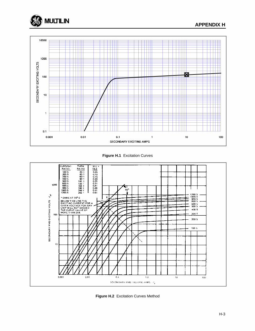
APPENDIX H
H-3
Figure H.1 Excitation Curves
Figure H.2 Excitation Curves Method
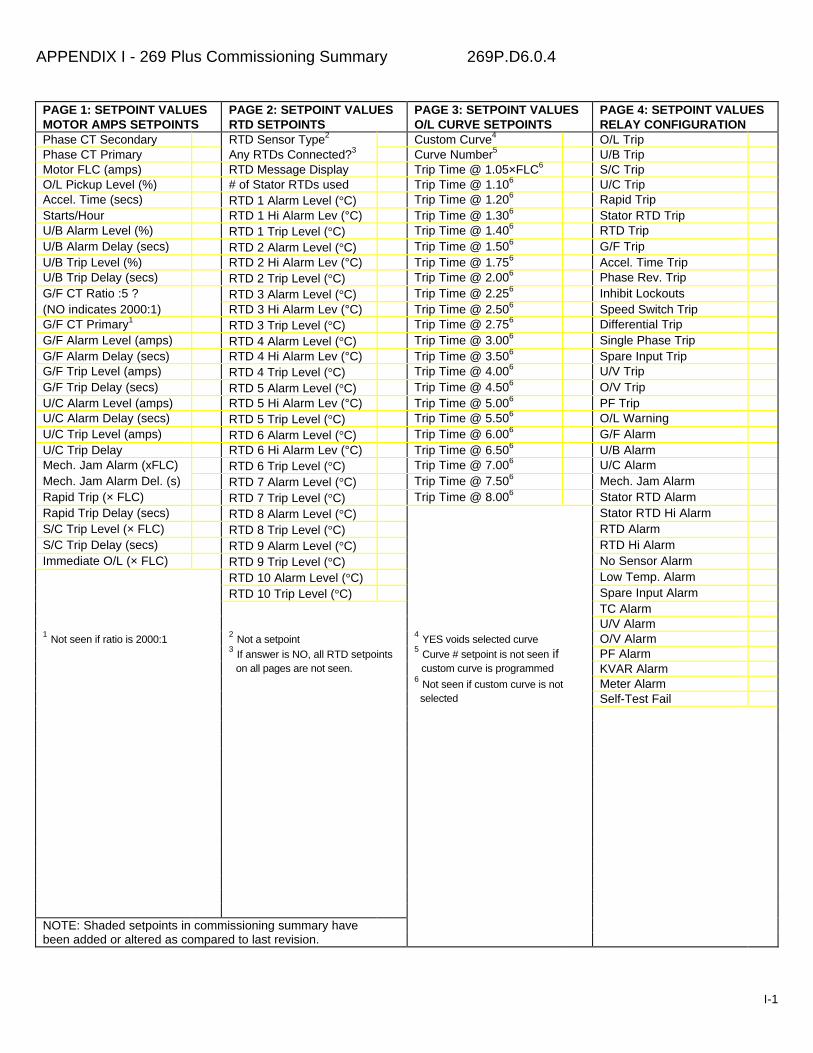
APPENDIX I - 269 Plus Commissioning Summary 269P.D6.0.4
I-1
PAGE 1: SETPOINT VALUESMOTOR AMPS SETPOINTS
PAGE 2: SETPOINT VALUESRTD SETPOINTS
PAGE 3: SETPOINT VALUESO/L CURVE SETPOINTS
PAGE 4: SETPOINT VALUESRELAY CONFIGURATION
Phase CT Secondary RTD Sensor Type2 Custom Curve4 O/L TripPhase CT Primary Any RTDs Connected?3 Curve Number5 U/B TripMotor FLC (amps) RTD Message Display Trip Time @ 1.05×FLC6 S/C TripO/L Pickup Level (%) # of Stator RTDs used Trip Time @ 1.106 U/C TripAccel. Time (secs) RTD 1 Alarm Level (°C) Trip Time @ 1.206 Rapid TripStarts/Hour RTD 1 Hi Alarm Lev (°C) Trip Time @ 1.306 Stator RTD TripU/B Alarm Level (%) RTD 1 Trip Level (°C) Trip Time @ 1.406 RTD TripU/B Alarm Delay (secs) RTD 2 Alarm Level (°C) Trip Time @ 1.506 G/F TripU/B Trip Level (%) RTD 2 Hi Alarm Lev (°C) Trip Time @ 1.756 Accel. Time TripU/B Trip Delay (secs) RTD 2 Trip Level (°C) Trip Time @ 2.006 Phase Rev. TripG/F CT Ratio :5 ? RTD 3 Alarm Level (°C) Trip Time @ 2.256 Inhibit Lockouts(NO indicates 2000:1) RTD 3 Hi Alarm Lev (°C) Trip Time @ 2.506 Speed Switch TripG/F CT Primary1
RTD 3 Trip Level (°C) Trip Time @ 2.756 Differential TripG/F Alarm Level (amps) RTD 4 Alarm Level (°C) Trip Time @ 3.006 Single Phase TripG/F Alarm Delay (secs) RTD 4 Hi Alarm Lev (°C) Trip Time @ 3.506 Spare Input TripG/F Trip Level (amps) RTD 4 Trip Level (°C) Trip Time @ 4.006 U/V TripG/F Trip Delay (secs) RTD 5 Alarm Level (°C) Trip Time @ 4.506 O/V TripU/C Alarm Level (amps) RTD 5 Hi Alarm Lev (°C) Trip Time @ 5.006 PF TripU/C Alarm Delay (secs) RTD 5 Trip Level (°C) Trip Time @ 5.506 O/L WarningU/C Trip Level (amps) RTD 6 Alarm Level (°C) Trip Time @ 6.006 G/F AlarmU/C Trip Delay RTD 6 Hi Alarm Lev (°C) Trip Time @ 6.506 U/B AlarmMech. Jam Alarm (xFLC) RTD 6 Trip Level (°C) Trip Time @ 7.006 U/C AlarmMech. Jam Alarm Del. (s) RTD 7 Alarm Level (°C) Trip Time @ 7.506 Mech. Jam AlarmRapid Trip (× FLC) RTD 7 Trip Level (°C) Trip Time @ 8.006 Stator RTD AlarmRapid Trip Delay (secs) RTD 8 Alarm Level (°C) Stator RTD Hi AlarmS/C Trip Level (× FLC) RTD 8 Trip Level (°C) RTD AlarmS/C Trip Delay (secs) RTD 9 Alarm Level (°C) RTD Hi AlarmImmediate O/L (× FLC) RTD 9 Trip Level (°C) No Sensor Alarm
RTD 10 Alarm Level (°C) Low Temp. AlarmRTD 10 Trip Level (°C) Spare Input Alarm
TC AlarmU/V Alarm
1 Not seen if ratio is 2000:1 2 Not a setpoint 4 YES voids selected curve O/V Alarm3 If answer is NO, all RTD setpoints 5 Curve # setpoint is not seen if PF Alarm on all pages are not seen. custom curve is programmed KVAR Alarm
6 Not seen if custom curve is not Meter Alarm selected Self-Test Fail
NOTE: Shaded setpoints in commissioning summary havebeen added or altered as compared to last revision.
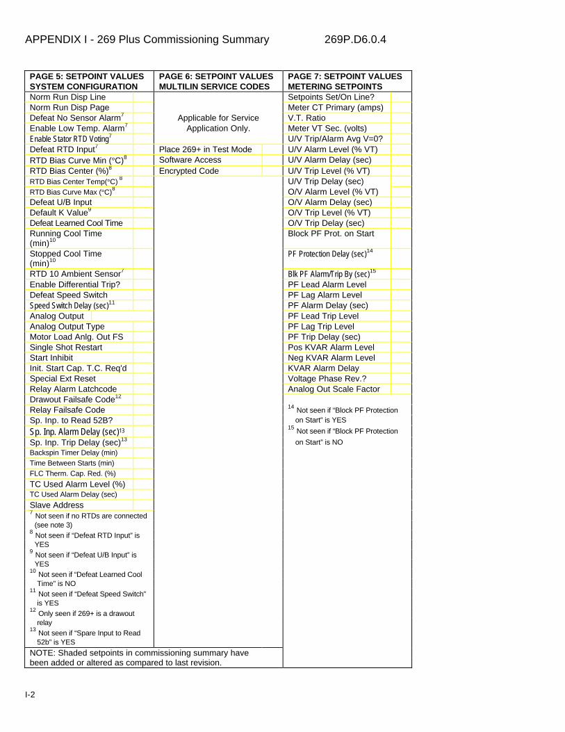
APPENDIX I - 269 Plus Commissioning Summary 269P.D6.0.4
I-2
PAGE 5: SETPOINT VALUESSYSTEM CONFIGURATION
PAGE 6: SETPOINT VALUESMULTILIN SERVICE CODES
PAGE 7: SETPOINT VALUESMETERING SETPOINTS
Norm Run Disp Line Setpoints Set/On Line?Norm Run Disp Page Meter CT Primary (amps)Defeat No Sensor Alarm7 Applicable for Service V.T. RatioEnable Low Temp. Alarm7 Application Only. Meter VT Sec. (volts)Enable Stator RTD Voting7 U/V Trip/Alarm Avg V=0?Defeat RTD Input7 Place 269+ in Test Mode U/V Alarm Level (% VT)RTD Bias Curve Min (°C)8 Software Access U/V Alarm Delay (sec)RTD Bias Center (%)8 Encrypted Code U/V Trip Level (% VT)RTD Bias Center Temp(°C) 8 U/V Trip Delay (sec)RTD Bias Curve Max (°C)8 O/V Alarm Level (% VT)Defeat U/B Input O/V Alarm Delay (sec)Default K Value9 O/V Trip Level (% VT)Defeat Learned Cool Time O/V Trip Delay (sec)Running Cool Time(min)10
Block PF Prot. on Start
Stopped Cool Time(min)10
PF Protection Delay (sec)14
RTD 10 Ambient Sensor7 Blk PF Alarm/Trip By (sec)15
Enable Differential Trip? PF Lead Alarm LevelDefeat Speed Switch PF Lag Alarm LevelSpeed Switch Delay (sec)11 PF Alarm Delay (sec)Analog Output PF Lead Trip LevelAnalog Output Type PF Lag Trip LevelMotor Load Anlg. Out FS PF Trip Delay (sec)Single Shot Restart Pos KVAR Alarm LevelStart Inhibit Neg KVAR Alarm LevelInit. Start Cap. T.C. Req’d KVAR Alarm DelaySpecial Ext Reset Voltage Phase Rev.?Relay Alarm Latchcode Analog Out Scale FactorDrawout Failsafe Code12
Relay Failsafe Code 14 Not seen if “Block PF ProtectionSp. Inp. to Read 52B? on Start” is YES
Sp. Inp. Alarm Delay (sec)13 15 Not seen if “Block PF Protection
Sp. Inp. Trip Delay (sec)13 on Start” is NOBackspin Timer Delay (min)Time Between Starts (min)FLC Therm. Cap. Red. (%)
TC Used Alarm Level (%)TC Used Alarm Delay (sec)
Slave Address7 Not seen if no RTDs are connected (see note 3)8 Not seen if “Defeat RTD Input” is YES9 Not seen if “Defeat U/B Input” is YES10 Not seen if “Defeat Learned Cool Time” is NO11 Not seen if “Defeat Speed Switch” is YES12 Only seen if 269+ is a drawout relay13 Not seen if “Spare Input to Read 52b” is YES
NOTE: Shaded setpoints in commissioning summary havebeen added or altered as compared to last revision.

APPENDIX I - 269 Plus Commissioning Summary 269P.D6.0.4
I-3
PAGE 1: SETPOINT VALUESMOTOR AMPS SETPOINTS
PAGE 2: SETPOINT VALUESRTD SETPOINTS
PAGE 3: SETPOINT VALUESO/L CURVE SETPOINTS
PAGE 4: SETPOINT VALUESRELAY CONFIGURATION
Phase CT Secondary RTD Sensor Type2 Custom Curve4 O/L TripPhase CT Primary Any RTDs Connected?3 Curve Number5 U/B TripMotor FLC (amps) RTD Message Display Trip Time @ 1.05×FLC6 S/C TripO/L Pickup Level (%) # of Stator RTDs used Trip Time @ 1.106 U/C TripAccel. Time (secs) RTD 1 Alarm Level (°C) Trip Time @ 1.206 Rapid TripStarts/Hour RTD 1 Hi Alarm Lev (°C) Trip Time @ 1.306 Stator RTD TripU/B Alarm Level (%) RTD 1 Trip Level (°C) Trip Time @ 1.406 RTD TripU/B Alarm Delay (secs) RTD 2 Alarm Level (°C) Trip Time @ 1.506 G/F TripU/B Trip Level (%) RTD 2 Hi Alarm Lev (°C) Trip Time @ 1.756 Accel. Time TripU/B Trip Delay (secs) RTD 2 Trip Level (°C) Trip Time @ 2.006 Phase Rev. TripG/F CT Ratio :5 ? RTD 3 Alarm Level (°C) Trip Time @ 2.256 Inhibit Lockouts(NO indicates 2000:1) RTD 3 Hi Alarm Lev (°C) Trip Time @ 2.506 Speed Switch TripG/F CT Primary1
RTD 3 Trip Level (°C) Trip Time @ 2.756 Differential TripG/F Alarm Level (amps) RTD 4 Alarm Level (°C) Trip Time @ 3.006 Single Phase TripG/F Alarm Delay (secs) RTD 4 Hi Alarm Lev (°C) Trip Time @ 3.506 Spare Input TripG/F Trip Level (amps) RTD 4 Trip Level (°C) Trip Time @ 4.006 U/V TripG/F Trip Delay (secs) RTD 5 Alarm Level (°C) Trip Time @ 4.506 O/V TripU/C Alarm Level (amps) RTD 5 Hi Alarm Lev (°C) Trip Time @ 5.006 PF TripU/C Alarm Delay (secs) RTD 5 Trip Level (°C) Trip Time @ 5.506 O/L WarningU/C Trip Level (amps) RTD 6 Alarm Level (°C) Trip Time @ 6.006 G/F AlarmU/C Trip Delay RTD 6 Hi Alarm Lev (°C) Trip Time @ 6.506 U/B AlarmMech. Jam Alarm (xFLC) RTD 6 Trip Level (°C) Trip Time @ 7.006 U/C AlarmMech. Jam Alarm Del. (s) RTD 7 Alarm Level (°C) Trip Time @ 7.506 Mech. Jam AlarmRapid Trip (× FLC) RTD 7 Trip Level (°C) Trip Time @ 8.006 Stator RTD AlarmRapid Trip Delay (secs) RTD 8 Alarm Level (°C) Stator RTD Hi AlarmS/C Trip Level (× FLC) RTD 8 Trip Level (°C) RTD AlarmS/C Trip Delay (secs) RTD 9 Alarm Level (°C) RTD Hi AlarmImmediate O/L (× FLC) RTD 9 Trip Level (°C) No Sensor Alarm
RTD 10 Alarm Level (°C) Low Temp. AlarmRTD 10 Trip Level (°C) Spare Input Alarm
TC AlarmU/V Alarm
1 Not seen if ratio is 2000:1 2 Not a setpoint 4 YES voids selected curve O/V Alarm3 If answer is NO, all RTD setpoints 5 Curve # setpoint is not seen if PF Alarm on all pages are not seen. custom curve is programmed KVAR Alarm
6 Not seen if custom curve is not Meter Alarm selected Self-Test Fail
NOTE: Shaded setpoints in commissioning summary havebeen added or altered as compared to last revision.

APPENDIX I - 269 Plus Commissioning Summary 269P.D6.0.4
I-4
PAGE 5: SETPOINT VALUESSYSTEM CONFIGURATION
PAGE 6: SETPOINT VALUESMULTILIN SERVICE CODES
PAGE 7: SETPOINT VALUESMETERING SETPOINTS
Norm Run Disp Line Setpoints Set/On Line?Norm Run Disp Page Meter CT Primary (amps)Defeat No Sensor Alarm7 Applicable for Service V.T. RatioEnable Low Temp. Alarm7 Application Only. Meter VT Sec. (volts)Enable Stator RTD Voting7 U/V Trip/Alarm Avg V=0?Defeat RTD Input7 Place 269+ in Test Mode U/V Alarm Level (% VT)RTD Bias Curve Min (°C)8 Software Access U/V Alarm Delay (sec)RTD Bias Center (%)8 Encrypted Code U/V Trip Level (% VT)RTD Bias Center Temp(°C) 8 U/V Trip Delay (sec)RTD Bias Curve Max (°C)8 O/V Alarm Level (% VT)Defeat U/B Input O/V Alarm Delay (sec)Default K Value9 O/V Trip Level (% VT)Defeat Learned Cool Time O/V Trip Delay (sec)Running Cool Time(min)10
Block PF Prot. on Start
Stopped Cool Time(min)10
PF Protection Delay (sec)14
RTD 10 Ambient Sensor7 Blk PF Alarm/Trip By (sec)15
Enable Differential Trip? PF Lead Alarm LevelDefeat Speed Switch PF Lag Alarm LevelSpeed Switch Delay (sec)11 PF Alarm Delay (sec)Analog Output PF Lead Trip LevelAnalog Output Type PF Lag Trip LevelMotor Load Anlg. Out FS PF Trip Delay (sec)Single Shot Restart Pos KVAR Alarm LevelStart Inhibit Neg KVAR Alarm LevelInit. Start Cap. T.C. Req’d KVAR Alarm DelaySpecial Ext Reset Voltage Phase Rev.?Relay Alarm Latchcode Analog Out Scale FactorDrawout Failsafe Code12
Relay Failsafe Code 14 Not seen if “Block PF ProtectionSp. Inp. to Read 52B? on Start” is YES
Sp. Inp. Alarm Delay (sec)13 15 Not seen if “Block PF Protection
Sp. Inp. Trip Delay (sec)13 on Start” is NOBackspin Timer Delay (min)Time Between Starts (min)FLC Therm. Cap. Red. (%)
TC Used Alarm Level (%)TC Used Alarm Delay (sec)
Slave Address7 Not seen if no RTDs are connected (see note 3)8 Not seen if “Defeat RTD Input” is YES9 Not seen if “Defeat U/B Input” is YES10 Not seen if “Defeat Learned Cool Time” is NO11 Not seen if “Defeat Speed Switch” is YES12 Only seen if 269+ is a drawout relay13 Not seen if “Spare Input to Read 52b” is YES
NOTE: Shaded setpoints in commissioning summary havebeen added or altered as compared to last revision.
GLOSSARY
Active - Refers to the state of an output relay. Anoutput relay will become active (activate) when any ofthe functions assigned to that relay indicate a trip/alarmcondition.
Inactive - Refers to the state of an output relay. Anoutput relay will be inactive whenever none of theconditions assigned to that relay indicate trip/alarmconditions.
Latched - Refers to the configuration of an outputrelay. Latched relays must be manually reset afteractivation. This can be done by using the Reset key orthe External Reset terminals. Trip and Aux. 2 relaysare always latched.
Unlatched - Refers to the configuration of an outputrelay. An unlatched relay will be automatically resetafter the conditions causing its activation are removed.
Fail-safe (FS) - Refers to the configuration of an outputrelay. When a fail-safe relay is in the no trip/no alarm(inactive) state its coil will be energized (ie. have avoltage across it). Thus when control power isremoved from the 269 all fail-safe output relays will goto the active state. Aux. 2 relay is always fail-safe.
Non-fail-safe (NFS) - Refers to the configuration of anoutput relay. When a non-fail-safe relay is in the notrip/no alarm state its coil will be de-energized (ie. haveno voltage across it). Thus when control power isremoved from the 269 relay all non-fail-safe outputrelays will go to the inactive state.
Tripped - Refers to the state of the motor controller,starter, or system circuit breaker. When one of thesedevices is tripped the power to the motor will beremoved. Normally the Trip relay of the 269 is used tocontrol this operation.
Mode - The large amount of information that can beviewed on the 269 relay display is divided into fourmodes: ACTUAL VALUES, SETPOINTS, HELP, andTRIP/ALARM. The relay can be put into any one ofthese modes for viewing specific information. TheACTUAL VALUES and SETPOINTS modes eachcontain many pages of data while all four modescontain many lines.
Page - The ACTUAL VALUES and SETPOINTS modesare divided into a number of pages containing differentsets of information. Each page contains many lines,only one of which can be viewed on the display at anyone time.
Line - Each relay display mode is divided into anumber of lines of data. Each line consists of 2 rows X24 characters. One line will always be visible on the269 relay display.Flash Message - Flash messages are one linemessages that appear on the display in response to
certain key closures or timer indications. Flashmessages stay on the display for 2 seconds.
Thermal Memory - This is an internal 269 relayregister which is used to thermally model the motorbeing protected. When this register reaches a value of100% the entire thermal capacity of the motor has beenused and an OVERLOAD TRIP is initiated.
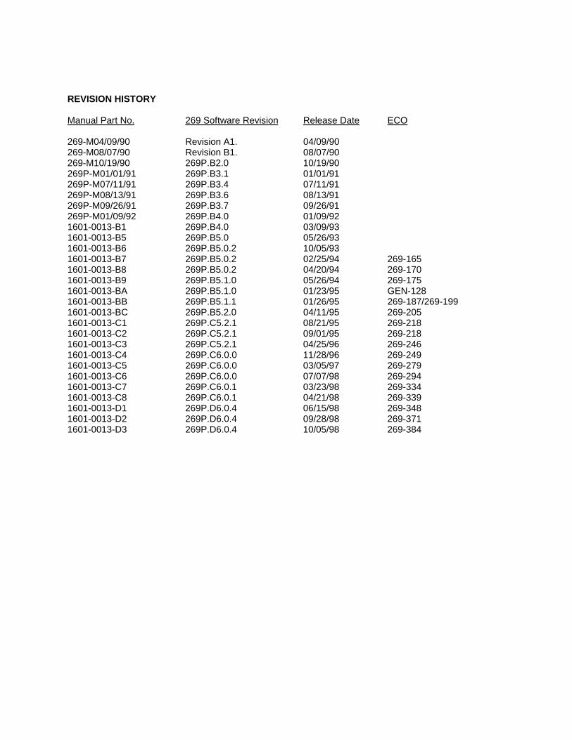
REVISION HISTORY
Manual Part No. 269 Software Revision Release Date ECO
269-M04/09/90 Revision A1. 04/09/90269-M08/07/90 Revision B1. 08/07/90269-M10/19/90 269P.B2.0 10/19/90269P-M01/01/91 269P.B3.1 01/01/91269P-M07/11/91 269P.B3.4 07/11/91269P-M08/13/91 269P.B3.6 08/13/91269P-M09/26/91 269P.B3.7 09/26/91269P-M01/09/92 269P.B4.0 01/09/921601-0013-B1 269P.B4.0 03/09/931601-0013-B5 269P.B5.0 05/26/931601-0013-B6 269P.B5.0.2 10/05/931601-0013-B7 269P.B5.0.2 02/25/94 269-1651601-0013-B8 269P.B5.0.2 04/20/94 269-1701601-0013-B9 269P.B5.1.0 05/26/94 269-1751601-0013-BA 269P.B5.1.0 01/23/95 GEN-1281601-0013-BB 269P.B5.1.1 01/26/95 269-187/269-1991601-0013-BC 269P.B5.2.0 04/11/95 269-2051601-0013-C1 269P.C5.2.1 08/21/95 269-2181601-0013-C2 269P.C5.2.1 09/01/95 269-2181601-0013-C3 269P.C5.2.1 04/25/96 269-2461601-0013-C4 269P.C6.0.0 11/28/96 269-2491601-0013-C5 269P.C6.0.0 03/05/97 269-2791601-0013-C6 269P.C6.0.0 07/07/98 269-2941601-0013-C7 269P.C6.0.1 03/23/98 269-3341601-0013-C8 269P.C6.0.1 04/21/98 269-3391601-0013-D1 269P.D6.0.4 06/15/98 269-3481601-0013-D2 269P.D6.0.4 09/28/98 269-3711601-0013-D3 269P.D6.0.4 10/05/98 269-384
INDEX
00-1mA, 2-18, 3-330-20mA, 2-18, 3-33
22000:1, 2-15, 3-18, 3-5544-20mA, 1-3, 2-18, 2-26, 3-33, 3-68, 5-5, 6-1
Aacceleration, 1-1, 1-4, 2-15, 3-14, 3-50acceleration time, 1-3acceleration time trips, 3-11access terminal, 3-38actual values, 3-67, 4-5alarm relay, 1-2, 1-3alarms, 2-7, 2-16, 2-17, 3-47, 5-5ambient, 2-17, 3-9ambient air temperature, 1-3, 2-17, 3-31, 3-57, 3-64ambient temperature, 1-4, 2-17, 3-29, 3-48, 3-49, 3-64,7-1analog output, 2-18, 2-25, 2-26, 3-33, 3-46, 3-68, 5-5,6-1asynchronous, 4-1auxiliary relay, 2-16auxiliary relays, 1-2, 1-3average
of 3 phases, 3-30, 3-62phase current, 3-50, 3-56stator RTD temperature, 3-64voltage, 1-3
average voltage, 2-26, 3-42
Bbaud rate, 4-1
Ccalibration, 3-39, 5-5cause of last event, 3-16celsius, 3-9commissioning, 1-2, 3-5, 5-1communication, 2-19, 2-20, 3-37, 3-41, 3-67, 4-1, 4-3,4-4control power, 1-2, 2-12, 2-15, 3-2, 3-6, 3-17, 3-62, 3-66, 5-5, 6-1, 7-1CRC. See cyclic redundancy checkcurrent unbalance, 1-3, 3-50, 3-57, 3-62, 6-4custom curve, 1-1, 3-25custom overload curve, 1-3, 1-4, 3-58cyclic loads, 3-54cyclic redundancy check, 4-4
Ddefault display, 3-16default setpoints, 5-4, 5-5
default settings, 3-6, 3-15default times, 3-31dielectric strength, 3-54, 5-5differential input trips, 3-11differential relay, 1-1, 1-3, 2-19, 3-49differential trip, 3-32dimensions, 2-1, 2-20display, 2-1, 3-2drawout
case, 2-21, 5-5cradle, 2-21relay, 1-5, 2-21, 2-22, 3-35
Eemergency restart, 1-1, 1-3, 3-65error checking, 4-4external differential relay, 2-19external reset, 2-18, 3-34external speed switch, 2-19external switch, 2-19, 6-1
Ffaceplate, 2-21factory default settings, 3-6, 3-15factory values, 3-27fahrenheit, 3-9failsafe, 2-9, 2-16frequency, 1-7, 2-18, 2-27, 3-54fuse, 2-12
GGE Multilin 50:0.025 CT, 3-18ground CT, 2-15ground current, 2-15ground fault, 1-1, 1-2, 2-1, 2-15, 2-16, 3-7, 3-54, 3-55,3-56, 5-1, 5-4, 5-5, 6-1, 7-1ground fault trips, 3-11ground resistor, 3-55grounded system, 3-54, 3-55
Hhardware configuration, 2-21, 3-35hardware failure, 3-66
Iinduction motor, 3-50inhibit lockouts, 3-4initial start capacity, 3-34installation, 5-1
KK factor, 1-1, 1-3, 3-14, 3-30, 6-4keypad, 2-1, 3-2kvar, 2-26kW, 2-26
INDEX
LLCD, 3-7learned cooling, 3-64liquid crystal display, 3-7lockout time, 3-16, 3-31, 3-64loss of load, 1-1, 3-55
Mmaximum ground current, 2-15mechanical jam, 1-4, 2-16, 5-5memory map, 4-5meter
analog output, 2-26meter revision, 2-26metering data, 3-15metering setpoints, 3-41motor cooling, 2-17, 3-31, 3-64motor cooling time, 3-14motor load, 3-54, 3-55, 3-64, 5-5motor running, 1-2, 3-7, 3-17, 5-5, 7-1motor running hours, 3-11motor starting, 3-14, 3-50, 3-62motor starts, 1-1, 3-11, 3-48, 3-51, 3-56motor stopped, 5-5, 7-1MPM
analog output, 2-26communication wiring, 2-26control power, 2-25CT inputs, 2-25external connections, 2-25serial communications port, 2-26VT inputs, 2-25wiring, 2-25
MTM. See also meterMultilin
encrypted security access code, 3-39service use only, 3-39
Multilin 50:0.025 CT, 2-15, 3-55MWh, 2-27
Nnegative kvar, 3-46negative sequence current, 1-1, 1-3, 3-54, 3-62, 6-4
Ooutput relays, 1-2, 2-12, 2-15, 3-4, 3-27, 3-38, 3-51, 3-57, 3-66, 5-5, 6-1, 7-1overload curve, 1-1, 1-3, 1-4, 3-50, 3-57, 3-58, 3-62, 3-67, 5-5, 7-1overload pickup, 3-50, 3-57, 3-64overload warning, 3-55overvoltage, 3-43overvoltage trips, 3-11
PPF protection, 3-44phase CT primary, 2-15, 3-41
phase reversal, 3-11, 3-46, 3-68positive kvar, 3-45positive sequence current, 3-7, 3-12, 5-4, 6-4power consumption, 1-7, 2-12power factor, 2-26, 3-44, 3-45, 3-67, 3-68power factor trips, 3-11power measurement conventions, 3-68pulsating loads, 3-54
Rregister, 3-62, 4-1, 4-3, 4-4, 4-5, 6-1, 6-4relay overload trips, 3-11relay rapid trips, 3-11relay trips, 3-11relay unbalance trips, 3-11remote metering, 1-2remote reset, 2-18remote terminal unit, 4-1reset, 2-15, 2-18, 3-4, 4-3resetting, 3-16residual, 2-15restart, 2-18, 3-4RS232, 4-1RS485, 1-1, 1-2, 3-56, 4-1, 6-1RTD
average stator RTD temperature, 6-4bearing, 3-31, 3-57bias, 3-29, 3-30, 3-50, 3-57, 3-62, 3-64, 3-66, 5-5broken RTD sensor alarm, 3-28circuitry, 5-1hottest stator RTD, 1-2, 2-18inputs, 1-1, 1-3, 1-6low temp alarm, 3-28max stator RTD temperature, 1-2, 3-65measurement tests, 5-4open RTD, 3-57other, 3-56, 3-57RTD setpoints, 3-56sensor connections, 2-17sensor type, 3-21setpoints, 3-21stator, 1-3, 2-7, 2-15, 2-16, 3-7, 3-16, 3-29, 3-48, 3-49, 3-57stator RTD temperature, 1-1, 3-8, 3-12stator RTD voting, 3-29, 3-56, 5-4trips, 3-11
RTU. See remote terminal unit. See remote terminal unitrunning, 3-31running hours, 1-3, 3-66
SSCI box, 4-1serial number, 3-40setpoint read command, 4-5short circuit, 2-12, 2-15, 2-16, 3-56, 5-1, 5-5, 6-1, 7-1short circuit trips, 3-11single shot restart, 3-66software access, 3-39, 4-4
INDEX
software access code, 2-19solidly grounded system, 2-15spare input, 1-1, 1-3, 3-36special external reset, 3-34, 3-66specifications, 1-6speed switch, 1-1, 2-19, 3-32, 3-49speed switch trips, 3-11standard overload curves, 1-1, 1-3, 3-58start inhibit, 1-1starter, 2-15, 2-16starting current, 3-7, 3-14, 3-62starts/hour, 2-18, 3-16, 3-51, 3-65synchronous motor, 3-50
Ttemperature, 1-1, 2-17, 3-5, 3-62, 3-64, 3-66, 5-5, 6-1,7-1test mode, 3-38thermal capacity used, 2-18, 3-10, 3-32, 3-62, 3-63, 3-64, 3-65, 3-66, 5-5, 7-1thermal damage curve, 3-29thermal model, 3-62, 3-63time between starts, 2-18, 3-16timers, 3-7, 6-1, 6-4timing, 5-1trip relay, 1-2, 1-3, 2-9, 2-16, 3-5, 3-35, 5-5trips, 2-7, 2-16, 2-17, 2-18, 3-16, 3-66, 5-5two-wire isolated transmitter, 2-19
Uunbalance, 1-1, 1-2, 1-3, 2-15, 2-16, 3-30, 3-51, 3-54, 3-57, 3-62, 5-1, 5-4, 5-5unbalance bias, 3-30undercurrent, 1-4, 2-16, 3-55undervoltage, 3-42, 3-43undervoltage trips, 3-11
Vvoltage phase reversal, 2-26
Wwiring, 2-12
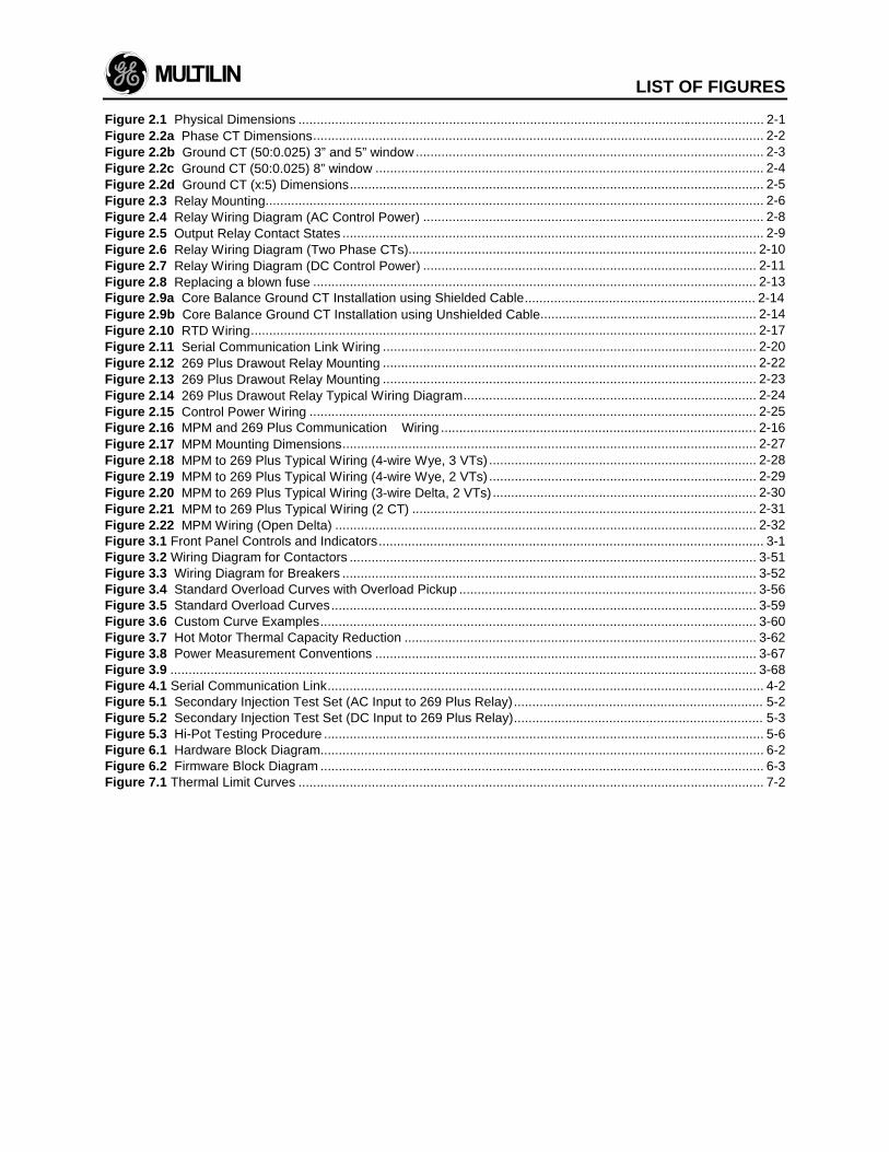
LIST OF FIGURES
Figure 2.1 Physical Dimensions ............................................................................................................................... 2-1Figure 2.2a Phase CT Dimensions........................................................................................................................... 2-2Figure 2.2b Ground CT (50:0.025) 3” and 5” window............................................................................................... 2-3Figure 2.2c Ground CT (50:0.025) 8” window .......................................................................................................... 2-4Figure 2.2d Ground CT (x:5) Dimensions................................................................................................................. 2-5Figure 2.3 Relay Mounting........................................................................................................................................ 2-6Figure 2.4 Relay Wiring Diagram (AC Control Power) ............................................................................................. 2-8Figure 2.5 Output Relay Contact States ................................................................................................................... 2-9Figure 2.6 Relay Wiring Diagram (Two Phase CTs)............................................................................................... 2-10Figure 2.7 Relay Wiring Diagram (DC Control Power) ........................................................................................... 2-11Figure 2.8 Replacing a blown fuse ......................................................................................................................... 2-13Figure 2.9a Core Balance Ground CT Installation using Shielded Cable............................................................... 2-14Figure 2.9b Core Balance Ground CT Installation using Unshielded Cable........................................................... 2-14Figure 2.10 RTD Wiring.......................................................................................................................................... 2-17Figure 2.11 Serial Communication Link Wiring ...................................................................................................... 2-20Figure 2.12 269 Plus Drawout Relay Mounting ...................................................................................................... 2-22Figure 2.13 269 Plus Drawout Relay Mounting ...................................................................................................... 2-23Figure 2.14 269 Plus Drawout Relay Typical Wiring Diagram................................................................................ 2-24Figure 2.15 Control Power Wiring .......................................................................................................................... 2-25Figure 2.16 MPM and 269 Plus Communication Wiring ...................................................................................... 2-16Figure 2.17 MPM Mounting Dimensions................................................................................................................. 2-27Figure 2.18 MPM to 269 Plus Typical Wiring (4-wire Wye, 3 VTs) ......................................................................... 2-28Figure 2.19 MPM to 269 Plus Typical Wiring (4-wire Wye, 2 VTs) ......................................................................... 2-29Figure 2.20 MPM to 269 Plus Typical Wiring (3-wire Delta, 2 VTs)........................................................................ 2-30Figure 2.21 MPM to 269 Plus Typical Wiring (2 CT) .............................................................................................. 2-31Figure 2.22 MPM Wiring (Open Delta) ................................................................................................................... 2-32Figure 3.1 Front Panel Controls and Indicators......................................................................................................... 3-1Figure 3.2 Wiring Diagram for Contactors ............................................................................................................... 3-51Figure 3.3 Wiring Diagram for Breakers ................................................................................................................. 3-52Figure 3.4 Standard Overload Curves with Overload Pickup ................................................................................. 3-56Figure 3.5 Standard Overload Curves.................................................................................................................... 3-59Figure 3.6 Custom Curve Examples....................................................................................................................... 3-60Figure 3.7 Hot Motor Thermal Capacity Reduction ................................................................................................ 3-62Figure 3.8 Power Measurement Conventions ........................................................................................................ 3-67Figure 3.9 ................................................................................................................................................................ 3-68Figure 4.1 Serial Communication Link....................................................................................................................... 4-2Figure 5.1 Secondary Injection Test Set (AC Input to 269 Plus Relay).................................................................... 5-2Figure 5.2 Secondary Injection Test Set (DC Input to 269 Plus Relay).................................................................... 5-3Figure 5.3 Hi-Pot Testing Procedure ........................................................................................................................ 5-6Figure 6.1 Hardware Block Diagram......................................................................................................................... 6-2Figure 6.2 Firmware Block Diagram ......................................................................................................................... 6-3Figure 7.1 Thermal Limit Curves ............................................................................................................................... 7-2

LIST OF TABLES
Table 1-1 Model 269 Plus Relay Features .......................................................................................................... 1-3Table 2-1 269 Plus External Connections ........................................................................................................... 2-7Table 3-1 Controls and Indicators ...................................................................................................................... 3-2Table 3-2 ACTUAL VALUES .............................................................................................................................. 3-7Table 3-3 SETPOINTS..................................................................................................................................... 3-18Table 3-4 TRIP/ALARM Messages and Fault Diagnosis ................................................................................... 3-47Table 3-5 Standard Overload Curve Trip Times (in seconds)............................................................................ 3-58Table 3-6 Preset Factory Relay Configurations and Functions.......................................................................... 3-69Table 4-1 Memory Map ...................................................................................................................................... 4-6Table 5-1 RTD Resistance vs. Temperature ....................................................................................................... 5-4

GE MULTILIN RELAY WARRANTY
General Electric Multilin Inc. (GE Multilin) warrants each relay it manufactures tobe free from defects in material and workmanship under normal use and servicefor a period of 24 months from date of shipment from factory.
In the event of a failure covered by warranty, GE Multilin will undertake to repair orreplace the relay providing the warrantor determined that it is defective and it isreturned with all transportation charges prepaid to an authorized service centre orthe factory. Repairs or replacement under warranty will be made without charge.
Warranty shall not apply to any relay which has been subject to misuse,negligence, accident, incorrect installation or use not in accordance withinstructions nor any unit that has been altered outside a GE Multilin authorizedfactory outlet.
GE Multilin is not liable for special, indirect or consequential damages or for loss ofprofit or for expenses sustained as a result of a relay malfunction, incorrectapplication or adjustment.
For complete text of Warranty (including limitations and disclaimers) refer to GEMultilin Standard Conditions of Sale.