Embed Size (px)
Citation preview

Chapter 2—Alternatives Considered
Draft Environmental Impact Statement/Environmental Impact Report 2-63
Figure 2-54. Santa Monica/San Vicente Station
Beverly Center Area Station
This station would be under San Vicente Boulevard, extending from just south of Gracie Allen Drive to south of Third Street (Figure 2-55). The three potential station entrances are on the south side of Third Street, mid-block between San Vicente and La Cienega Boulevards; on the northeast corner of the San Vicente Boulevard/Third Street intersection, in the Beverly Center Shopping Center; and on the northwest corner of San Vicente Boulevard and 3rd Street. A potential construction site is proposed on the south side of 3rd Street, between San Vicente and La Cienega Boulevards.
Figure 2-55. Beverly Center Area Station
2.7 Other Components of the Build Alternatives This section describes other components of the Build Alternatives that are assumed in the analysis of project costs and impacts.
2.7.1 Traction Power Substations
Traction power substations (TPSS) are required to provide traction power for the HRT system. Substations would be located in the station box or in the crossover box and would be located in a room that is about 50 feet by 100 feet in a below grade structure. Table 2-5 identifies the locations of the substations.

2-64 Westside Subway Extension September 2010
2.7.2 Emergency Generators
Table 2-5 also lists the locations of the emergency generators. The stations at which the emergency generators would be located are Wilshire/La Brea, Wilshire/La Cienega, Westwood/UCLA, Westwood/VA Hospital, Wilshire/26th, Highland/Hollywood, Santa Monica/La Brea, and Santa Monica/San Vicente. The emergency generators would require approximately 50 feet by 100 feet of property in an off-street location.
All emergency generators would require property acquisition, except for the one at the Wilshire/La Brea Station which uses Metro’s property. The emergency generator at the Wilshire/La Brea Station would be located on the Metro property on the north side of Wilshire Boulevard between La Brea Avenue and Detroit Street. The emergency generator at the Wilshire/La Cienega Station would be located on the southwest corner of Wilshire Boulevard and Gale Drive. The emergency generator at Westwood/UCLA would be located in UCLA Lot 36, on the north side of Wilshire Boulevard in between Gayley Avenue and Veteran Avenue. The emergency generator at Westwood/VA Hospital would be located on the VA Hospital property. The emergency generator at the Wilshire/26th Station would be located on the northwest corner of Wilshire Boulevard and 26th Street. The emergency generator at the Hollywood/Highland Station would be located on the northwest corner of Highland Avenue and Hawthorn Avenue. The emergency generator at the Santa Monica/La Brea Station would be located on the northwest corner of Santa Monica Boulevard and La Brea Avenue. The emergency generator at the Santa Monica/San Vicente Station would be located on the south side of Santa Monica Boulevard, just west of Huntley Drive, on the Metro property.

Chapter 2—Alternatives Considered
Draft Environmental Impact Statement/Environmental Impact Report 2-65
2.7.3 Mid-Tunnel Vent Shaft
Each alternative would require mid-tunnel ventilation shafts (Table 2-6). The vent shafts are emergency ventilation shafts with dampers, fans, and sound attenuators generally placed at both ends of a station box for exhausting smoke. The vent shafts are also required in tunnel segments with more than 6,000 feet between stations to meet fire/life safety requirements.
Due to fire/life safety procedures in accordance with National Fire Protection Association 130 (Standard for Fixed Guideway Transit and Passenger Rail Systems) and operating policies, mid-tunnel vent shafts may be required in certain areas to maintain train throughput for increased headways of 24 to 30 trains per hour. There would be a connecting corridor between the two tunnels (one for each direction of train movement) to provide emergency egress and fire-fighting ingress. In addition to exhausting smoke, emergency vent shafts could be used for station cooling and gas mitigation. A vent shaft is approximately 150 square feet; with the opening of the shaft located in a sidewalk and covered with a grate about 200 square feet.
Table 2-5: Substation and Emergency Generator Locations
Station TPSS Emergency Generators
Wilshire/Crenshaw X
Wilshire/La Brea X X1
Wilshire/Fairfax X
Wilshire/La Cienega X X2
Transition Structure GBS
Wilshire/Rodeo X
Century City (Santa Monica) X
Mid-Tunnel Vent Shaft
Westwood/UCLA X X3
Westwood/VA Hospital X4
Wilshire/Bundy X
Wilshire/26th X X5
Wilshire/16th X
Wilshire/4th X
Hollywood/Highland X X
Santa Monica/La Brea X X6
Santa Monica/Fairfax X
Santa Monica/San Vicente X X7
Beverly Center Area X
Optional Stations
Wilshire/Fairfax (East) X
Wilshire/La Cienega (Transfer Station - West)
X
Century City (Constellation) X
Westwood/UCLA (On Street) X X3
Westwood/VA Hospital (North) X4
1Emergency generator at Wilshire/La Brea would also feed Crenshaw and Fairfax Stations. 2Emergency generator at Wilshire/La Cienega would also feed Wilshire/Rodeo Station. 3Emergency generator at Westwood/UCLA would also feed Century City Station and Mid-Tunnel Vent Shaft. 4Emergency generator at Westwood/VA Hospital would also feed vent shaft (see below in Section 2.6.3) and Wilshire/Bundy Station. 5Emergency generator at Wilshire/26th would also feed Wilshire/16th Street Station. 6Emergency generator at Santa Monica/La Brea would also feed Santa Monica/Fairfax Station. 7Emergency generator at Santa Monica/San Vicente would also feed Beverly Center Area Station.

2-66 Westside Subway Extension September 2010
Table 2-6. Mid-Tunnel Vent Shaft Locations
Alternative/Option Location
Alternatives 1 through 5, MOS 2 Part of the connection structure on Wilshire Boulevard, west of Robertson Boulevard
Alternatives 2 through 5 West of the Westwood/VA Hospital Station on Army Reserve property at Federal Avenue and Wilshire Boulevard
Option 4 via East route At Wilshire Boulevard/Manning Avenue intersection
Option 4 to Westwood/UCLA Off-Street Station via Central route
On Santa Monica Boulevard just west of Beverly Glen Boulevard
Option 4 to Westwood/UCLA On-Street Station via Central route
At Santa Monica Boulevard/Beverly Glen Boulevard intersection
Options 4 via West route At Santa Monica Boulevard/Glendon Avenue intersection
Options 4 from Constellation Station via Central route On Santa Monica Boulevard between Thayer and Pandora Avenues
Option from Constellation Station via West route On Santa Monica Boulevard just east of Glendon Avenue
2.7.4 Trackwork Options
Each Build Alternative would require components of special trackwork that provide for operational efficiency and safety. These components include the following:
Tail tracks—a track, or tracks, that extends beyond the end of a terminal station (the last station on a line) that allow for safe braking distances and storage of cars or switching trains between tracks for a return trip (the tail tracks for this Project extend a minimum of 450 feet beyond the end of a terminal station)
Pocket tracks—an additional track adjacent to the mainline tracks generally at terminal stations, connected at both ends with crossovers, used for temporary storage of trains (disabled or otherwise) and for switching trains between tracks
Crossovers—a pair of turnouts that connect two parallel rail tracks, allowing a train on one track to cross over to the other, and usually located near stations
Double crossovers—when two sets of crossovers are installed with a diamond, allowing trains to cross over to the other track in either direction from either track. The four-turnout configuration is called a double crossover
Table 2-7 describes the locations of these components for each alternative, which are shown in Figure 2-56 through Figure 2-60. These components are not optional and would be part of the Build Alternative selected as the LPA.
During the development of the alternatives, Metro Operations also requested consideration of additional double crossovers and pocket tracks. The additional trackwork would serve several purposes: to achieve desired headways with flexibility to respond to planned events, such as special events; and to allow for preventative maintenance work and unplanned incidents. Table 2-7 lists the locations of the additional double crossovers (Wilshire/Fairfax, Wilshire/La Cienega, and Wilshire/26th Stations). In addition, Metro Operations requested consideration of an additional pocket track west of the Wilshire/Rodeo Station, which would provide train storage and short turnback for a future West Hollywood Line. If the West Hollywood Line is not selected as the preferred alternative, this pocket track would not be required.

Chapter 2—Alternatives Considered
Draft Environmental Impact Statement/Environmental Impact Report 2-67
Table 2-7. Special Trackwork Locations
Station
1 2 3 4 5
Westwood/ UCLA Extension
Westwood/ VA Hospital Extension
Santa Monica Extension
Westwood/ VA Hospital
Extension Plus West Hollywood
Extension
Santa Monica Extension Plus
West Hollywood Extension
Special Trackwork Locations—Base Trackwork Alternatives Wilshire/Crenshaw None None None None None Wilshire/La Brea Double Crossover Double Crossover Double Crossover Double Crossover Double Crossover Wilshire/Fairfax None
MOS 1 Only: Terminus Station with Tail tracks
None MOS 1 Only: Terminus Station with Tail tracks
None MOS 1 Only: Terminus Station with Tail tracks
None MOS 1 Only: Terminus Station with Tail tracks
None MOS 1 Only: Terminus Station with Tail tracks
Wilshire/La Cienega None None None None None Station Option 3 -
Wilshire/La Cienega West
Turnouts Turnouts Turnouts
Wilshire/Robertson Connection Structure
Equilateral Turnouts - for future West Hollywood connection
Equilateral Turnouts - for future West Hollywood connection
Equilateral Turnouts - for future West Hollywood connection
Equilateral Turnouts Equilateral Turnouts
Wilshire/Rodeo None None None None None Century City Double Crossover
MOS 2 Only: Terminus Station with Double Crossover and tail tracks
Double Crossover MOS 2 Only: Terminus Station with Double Crossover and tail tracks
Double Crossover MOS 2 Only: Terminus Station with Double Crossover and tail tracks
Double Crossover MOS 2 Only: Terminus Station with Double Crossover and tail tracks
Double Crossover MOS 2 Only: Terminus Station with Double Crossover and tail tracks
Westwood/UCLA End Terminal with Double Crossover and tail tracks
Double Crossover Double Crossover Double Crossover Double Crossover
Westwood/VA Hospital
N/A End Terminal with Turnouts and tail tracks
Turnouts End Terminal with Turnouts and tail tracks
Turnouts
Wilshire/Bundy N/A N/A None N/A None Wilshire/26th N/A N/A None N/A None Wilshire/16th N/A N/A None N/A None Wilshire/4th N/A N/A End Terminal with
Double Crossover. Pocket Track with Double Crossover, Equilateral Turnouts and tail tracks
N/A End Terminal with Double Crossover, Pocket Track with Double Crossover, Equilateral Turnouts and tail tracks
Hollywood/ Highland
N/A N/A N/A Double Crossover and tail tracks
Double Crossover and tail tracks
Santa Monica/La Brea
N/A N/A N/A None
None
Santa Monica/Fairfax
N/A N/A N/A None None
Santa Monica/ San Vicente
N/A N/A N/A Double Crossover Double Crossover
Beverly Center N/A N/A N/A None None Additional Special Trackwork Location (Optional Trackwork) Wilshire/Fairfax Double Crossover Double Crossover Double Crossover Double Crossover Double Crossover Wilshire/La Cienega Double Crossover Double Crossover Double Crossover Double Crossover Double Crossover Wilshire/ Rodeo None None None Pocket Track Pocket Track Wilshire/26th N/A N/A Double Crossover N/A Double Crossover

2-68 Westside Subway Extension September 2010
Figure 2-56. Special Trackwork Locations for Alternative 1

Chapter 2—Alternatives Considered
Draft Environmental Impact Statement/Environmental Impact Report 2-69
Figure 2-57. Special Trackwork Locations for Alternative 2

2-70 Westside Subway Extension September 2010
Figure 2-58. Special Trackwork Locations for Alternative 3

Chapter 2—Alternatives Considered
Draft Environmental Impact Statement/Environmental Impact Report 2-71
Figure 2-59. Special Trackwork Locations for Alternative 4

2-72 Westside Subway Extension September 2010
Figure 2-60. Special Trackwork Locations for Alternative 5

Chapter 2—Alternatives Considered
Draft Environmental Impact Statement/Environmental Impact Report 2-73
2.7.5 Rail Operations Center
An important aspect of Metro’s expansion program is the operation of the existing Rail Operations Center (ROC) (Figure 2-61). The current ROC configuration has evolved over the years as new rail lines have been added and expanded, and does not have sufficient room to accommodate the new transit corridors and line extensions in Metro’s expansion program. The Build Alternatives assume an expanded ROC located along the Blue Line near Willowbrook Avenue East and Imperial Highway (Figure 2-62). Other potential options would be to expand and build on either the existing Gateway Building at Cesar E. Chavez and Vignes, or the existing Red Line Yard at One Santa Fe; however, these are conceptual plans and not evaluated in this Draft EIS/EIR.
Metro is considering options for a shared Operations Control Center (OCC). An OCC would combine operations, staff, and equipment of the Rail Operations Center (ROC) with the Bus Operations Center (BOC) into one facility that would serve the entire Metro system. Alternatives for a combined ROC/BOC include:
Alternative 1—Immediate implementation of ROC/BOC at Gateway—consolidates ROC/BOC at existing Gateway building located at Cesar E. Chavez and Vignes. Expands and builds upon the current BOC (5th floor of the Gateway building) and creating a single facility implement Westside Extension and all other planned lines.
Alternative 2—Immediate implementation of ROC/BOC at Rosa Parks—consolidates ROC/BOC at existing ROC building located near Wilmington/Imperial/Rosa Parks Station. Two phases include: Phase 1 which would combine ROC/BOC for Expo-2 and Foothill Extension implementation without need for new facility; and Phase 2 would construct new facility for implementation of Westside Extension and all other planned lines.
Alternative 3—Immediate implementation of ROC/BOC at One Santa Fe—consolidates ROC/BOC at existing Red Line Yard located at One Santa Fe, which requires construction of a completely new facility.
Alternative 4—Phased implementation of combined ROC/BOC at Rosa Parks—would be the same as Alternative 2 but defers consolidation of ROC/BOC until Phase 2.

2-74 Westside Subway Extension September 2010
Figure 2-61. Rail Operations Center and Maintenance Yard Sites
Figure 2-62. Rail Operations Center Expansion—Site Layout Study

Chapter 2—Alternatives Considered
Draft Environmental Impact Statement/Environmental Impact Report 2-75
Under the scope of this Draft EIS/EIR, Alternative 2 and 4 will be environmentally cleared for Rail Operations only (i.e., not for combined rail and bus operations).Maintenance Yards
Metro currently has a fleet size of 104 HRVs to operate the existing Metro Red/Metro Purple Lines. Increased service for the No Build Alternative would require an additional 42 HRVs, for a total fleet of 146 vehicles. HRVs required for the Build Alternatives range from 250 (Alternative 1) to 336 (Alternative 5). The number of additional vehicles over the No Build Alternative ranges from 104 HRVs (Alternative 1) to 190 HRVs (Alternative 5).
Currently, Metro stores and maintains its Red Line/Purple Line vehicle fleet at the existing Division 20 Maintenance and Storage Facility at the site bounded by 1st Avenue on the north, the Los Angeles River on the east, 4th Street on the south, and Santa Fe Avenue on the west (Figure 2-61). With a capacity to accommodate up to 200 HRVs, the yard currently has sufficient capacity to store 96 additional HRVs.
Several enhancements to the facility are planned and programmed. One is a turnback to allow trains to change direction more efficiently. In addition, since more frequent train service systemwide would put more mileage on Metro’s HRT vehicles, more frequent maintenance would be necessary. Additional planned improvements will increase capacity at Division 20 for major repairs, wheel truing, service and inspection, and blow down operations.
If any of the HRT Build Alternatives are chosen, additional storage capacity would be needed. The costs of the maintenance facility improvements are included in each Build Alternative’s capital cost estimate. Two options for providing this expanded capacity are as follows:
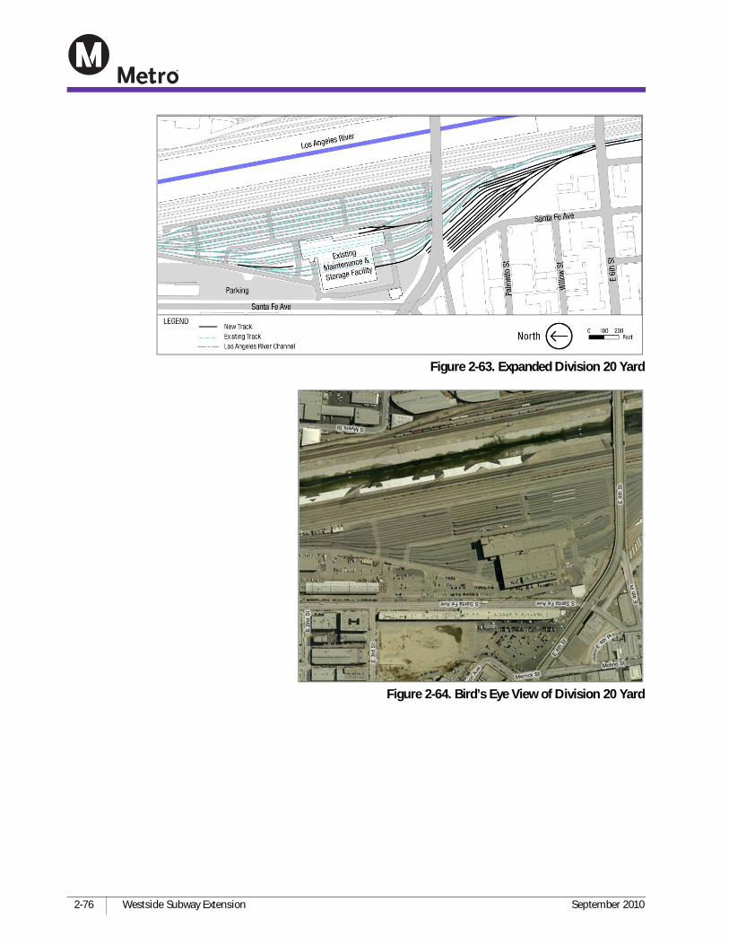
Additional storage immediately south of the Division 20 Maintenance and Storage Facility between the 4th and 6th Street Bridges (Figure 2-63 and Figure 2-64). This option would require purchasing 3.9 acres of vacant private property abutting the southern boundary of the existing facility, and the construction of additional maintenance and storage tracks. This would accommodate up to 102 vehicles, sufficient added capacity for Alternatives 1 and 2.
In the event that the existing Metro Red Line Rail Storage and Maintenance Yards could not be expanded to accommodate the Westside Subway Extension Project, a satellite facility could be built at the Union Pacific (UP) Los Angeles Transportation Center Rail Yard, connected by yard lead tracks to the Division 20 Maintenance and Storage Facility. This site has more than 123 acres, of which approximately 53 acres could be needed for the facility sufficient to accommodate the vehicle fleet for all five HRT alternatives. An additional 1.3 miles of track and a new bridge over the Los Angeles River would be constructed for vehicles to reach this yard (Figure 2-65). Figure 2-66 shows the UP railroad yard relative to the Division 20 Maintenance and Storage Facility.
2-76 Westside Subway Extension September 2010
Figure 2-63. Expanded Division 20 Yard
Figure 2-64. Bird’s Eye View of Division 20 Yard

Chapter 2—Alternatives Considered
Draft Environmental Impact Statement/Environmental Impact Report 2-77
2.8 Minimum Operable Segments The following two sections provide a description of the two MOSs identified for the Westside Subway project. In October 2009, Metro adopted its LRTP (LRTP, October 2009). In response to funding and phasing issues raised by fiscal constraints identified during the LRTP process, Metro developed MOSs that are shorter segments of the Project that could be constructed and operated. The MOSs are included in this Draft EIS/EIR as possible initial construction segments that would be constructed separately until further funding allowed construction of subsequent segments of the project alternatives.
In addition to describing each MOS, the sections discuss how potential environmental effects would need to be evaluated. The fact that the MOSs represent phases of the Build Alternatives that could be constructed and operated affects how potential environmental effects could occur. More specific information on environmental effects is presented in subsequent Chapters of this EIS/EIR.
The bus network for the MOSs would be the same as for any Build Alternative. As discussed in Section 2.4.1, in the future transit network, Line 920 would be eliminated and Line 720 would operate less frequently since its service route would be largely duplicated by the Wilshire Boulevard subway route. In the City of Los Angeles, headways (time between buses) for Line 720 are expected to be between 3 and 5 minutes under the existing network and between 5 and 11.5 minutes under the Build Alternatives. In the
Figure 2-66. Extension of Tracks to Reach UP Yard
Figure 2-65. UP Railroad Rail Bridge

2-78 Westside Subway Extension September 2010
City of Santa Monica, headways for Line 720 are expected to remain essentially unchanged. Future headways for Line 20 would remain unchanged within the City of Los Angeles, but in the City of Santa Monica, Line 20 service would be eliminated since it would be duplicated by the Santa Monica Blue Bus Line 2.
The potential interim termini at Wilshire/Fairfax or Century City would affect the assessment of potential environmental impact. The following summarizes major assessment items that would need to be addressed for the interim Wilshire/Fairfax and Century City Stations under MOS 1.
2.8.1 Transportation Items
Transit Ridership: With the MOS termini at Wilshire/Fairfax or Century City, the subway extension would generate higher overall ridership versus TSM and No Build Alternatives. Bus route modifications would not occur as a result of MOS and park-and-ride capacity is not provided at any of Westside extension station. Therefore, the environmental analysis relating to these items would not be affected by the interim terminus status.
Traffic Impacts: The development of subway stations could impact traffic, including pedestrian and bicycle operations. As an interim terminus, higher ridership volumes would potentially impact traffic operations at a greater level than if the station was not a terminus. The impact analysis discussed in Chapter 3 recognizes these higher ridership levels.
Parking: As is the case with all Westside Subway stations, there are no park-and-ride facilities at the Wilshire/Fairfax and Century City Stations. Estimates of potential spillover parking demand were based on potential theoretical maximum demand. They would not be affected by potential interim station termini.
Potential Station Impacts on Bicycle and Pedestrian Network: The analysis of potential impacts of station access on the pedestrian and bicycle network involved localized access is station areas. The interim termini would not affect the results.
Construction-Related Traffic: Construction-related traffic would be affected by decisions relating to locations of subway mining and related truck haul routes. If the Wilshire/Western Station is an interim terminus for the subway extension, location of truck haul routes could differ from those identified for a scenario involving the Build Alternatives.
Comparative Benefits and Costs
When assessing potential benefits and costs of MOS 1, the evaluation would need to take into account the value of time. While the MOS would be less costly to build versus the Build Alternatives, they would delay the investment required to complete the Westside Subway Extension.
Other Environmental Impacts
The development of the interim extension termini under MOS 1 and MOS 2 would not likely affect the approach to environmental analysis.

Chapter 2—Alternatives Considered
Draft Environmental Impact Statement/Environmental Impact Report 2-79
2.8.2 MOS 1—Fairfax Extension
MOS 1 is a phasing option that could be applied to any of the Build Alternatives . Due to funding constraints, it may be necessary to construct the Westside Subway Extension in shorter segments. The MOS 1 Alternative is presented in this Draft EIS/EIR to illustrate the potential costs, benefits, and impacts of a potential temporary terminus at the Wilshire/Fairfax Station.
MOS 1 follows the same alignment as Alternative 1, but terminates at the Wilshire/Fairfax Station rather than extending to the Westwood/UCLA Station. The alignment is 3.10 miles in length. Construction would take approximately 68 months. Assuming the currently adopted LRTP and current Measure R funding, MOS 1 would begin service in 2019.
A double crossover for MOS 1 is located on the west end of the Wilshire/La Brea Station box, west of Cloverdale Avenue (Figures 2-68 and 2-69). Tail tracks for MOS 1 are located west of the Wilshire/Fairfax Station.
Similar to the Build Alternatives, there are station and segment options. For a discussion of these refer to Section 2.5. The two station and segment options include:
Option 1—Wilshire/Crenshaw Station Option Option 2—Fairfax Station Option
2.8.3 MOS 2—Century City Extension
MOS 2 is the same alignment as Alternative 1 but this phase terminates at a Century City Station (Figure 2-15). The alignment is 6.61 miles from the Wilshire/Western Station to Century City. Construction would begin in 2020 and take approximately 72 months and. Assuming the currently adopted LRTP and current Measure R funding, MOS 2 would begin service in 2026.
Tail tracks for MOS 2 are located at the west end of a Century City Station (Figures 2-70 and 2-71).
Similar to the Build Alternatives, there are station and segment options. For a discussion of these refer to Section 2.5. The four station and segment options include:
Option 1—Wilshire/Crenshaw Station Option Option 2—Fairfax Station Option Option 3—La Cienega Station Option Option 4—Century City Station and Alignment Options

2-80 Westside Subway Extension September 2010
Figure 2-68. MOS 1—Fairfax Extension

Chapter 2—Alternatives Considered
Draft Environmental Impact Statement/Environmental Impact Report 2-81
Figure 2-69. Special Trackwork—MOS 1—Fairfax Extension

2-82 Westside Subway Extension September 2010
Figure 2-70. MOS 2—Century City Extension

Chapter 2—Alternatives Considered
Draft Environmental Impact Statement/Environmental Impact Report 2-83
Figure 2-71. Special Trackwork—MOS 2—Century City Extension


![Streets Are For Everybodymedia.metro.net/projects_studies/sustainability/cs_long_beach_david_roseman.pdfMicrosoft PowerPoint - Complete vs Incomplete Streets.pptx [Read-Only] Author:](https://img.pdfslide.net/doc/110x75/5f636e6f21e3cc5f2b1d35ce/streets-are-for-microsoft-powerpoint-complete-vs-incomplete-streetspptx-read-only.jpg)