Embed Size (px)
Citation preview

27 WAVE OPTICS
Figure 27.1 The colors reflected by this compact disc vary with angle and are not caused by pigments. Colors such as these are direct evidence of the wave character of light.(credit: Infopro, Wikimedia Commons)
Learning Objectives27.1. The Wave Aspect of Light: Interference
• Discuss the wave character of light.• Identify the changes when light enters a medium.
27.2. Huygens's Principle: Diffraction• Discuss the propagation of transverse waves.• Discuss Huygens’s principle.• Explain the bending of light.
27.3. Young’s Double Slit Experiment• Explain the phenomena of interference.• Define constructive interference for a double slit and destructive interference for a double slit.
27.4. Multiple Slit Diffraction• Discuss the pattern obtained from diffraction grating.• Explain diffraction grating effects.
27.5. Single Slit Diffraction• Discuss the single slit diffraction pattern.
27.6. Limits of Resolution: The Rayleigh Criterion• Discuss the Rayleigh criterion.
27.7. Thin Film Interference• Discuss the rainbow formation by thin films.
27.8. Polarization• Discuss the meaning of polarization.• Discuss the property of optical activity of certain materials.
27.9. *Extended Topic* Microscopy Enhanced by the Wave Characteristics of Light• Discuss the different types of microscopes.
CHAPTER 27 | WAVE OPTICS 955

Introduction to Wave OpticsExamine a compact disc under white light, noting the colors observed and locations of the colors. Determine if the spectra are formed by diffractionfrom circular lines centered at the middle of the disc and, if so, what is their spacing. If not, determine the type of spacing. Also with the CD, explorethe spectra of a few light sources, such as a candle flame, incandescent bulb, halogen light, and fluorescent light. Knowing the spacing of the rows ofpits in the compact disc, estimate the maximum spacing that will allow the given number of megabytes of information to be stored.
If you have ever looked at the reds, blues, and greens in a sunlit soap bubble and wondered how straw-colored soapy water could produce them, youhave hit upon one of the many phenomena that can only be explained by the wave character of light (see Figure 27.2). The same is true for thecolors seen in an oil slick or in the light reflected from a compact disc. These and other interesting phenomena, such as the dispersion of white lightinto a rainbow of colors when passed through a narrow slit, cannot be explained fully by geometric optics. In these cases, light interacts with smallobjects and exhibits its wave characteristics. The branch of optics that considers the behavior of light when it exhibits wave characteristics(particularly when it interacts with small objects) is called wave optics (sometimes called physical optics). It is the topic of this chapter.
Figure 27.2 These soap bubbles exhibit brilliant colors when exposed to sunlight. How are the colors produced if they are not pigments in the soap? (credit: Scott Robinson,Flickr)
27.1 The Wave Aspect of Light: InterferenceWe know that visible light is the type of electromagnetic wave to which our eyes respond. Like all other electromagnetic waves, it obeys the equation
(27.1)c = f λ,
where c = 3×10⁸ m/s is the speed of light in vacuum, f is the frequency of the electromagnetic waves, and λ is its wavelength. The range of
visible wavelengths is approximately 380 to 760 nm. As is true for all waves, light travels in straight lines and acts like a ray when it interacts withobjects several times as large as its wavelength. However, when it interacts with smaller objects, it displays its wave characteristics prominently.Interference is the hallmark of a wave, and in Figure 27.3 both the ray and wave characteristics of light can be seen. The laser beam emitted by theobservatory epitomizes a ray, traveling in a straight line. However, passing a pure-wavelength beam through vertical slits with a size close to thewavelength of the beam reveals the wave character of light, as the beam spreads out horizontally into a pattern of bright and dark regions caused bysystematic constructive and destructive interference. Rather than spreading out, a ray would continue traveling straight ahead after passing throughslits.
Making Connections: Waves
The most certain indication of a wave is interference. This wave characteristic is most prominent when the wave interacts with an object that isnot large compared with the wavelength. Interference is observed for water waves, sound waves, light waves, and (as we will see in SpecialRelativity) for matter waves, such as electrons scattered from a crystal.
956 CHAPTER 27 | WAVE OPTICS
This content is available for free at http://cnx.org/content/col11406/1.7

Figure 27.3 (a) The laser beam emitted by an observatory acts like a ray, traveling in a straight line. This laser beam is from the Paranal Observatory of the EuropeanSouthern Observatory. (credit: Yuri Beletsky, European Southern Observatory) (b) A laser beam passing through a grid of vertical slits produces an interferencepattern—characteristic of a wave. (credit: Shim'on and Slava Rybka, Wikimedia Commons)
Light has wave characteristics in various media as well as in a vacuum. When light goes from a vacuum to some medium, like water, its speed andwavelength change, but its frequency f remains the same. (We can think of light as a forced oscillation that must have the frequency of the original
source.) The speed of light in a medium is v = c / n , where n is its index of refraction. If we divide both sides of equation c = f λ by n , we get
c / n = v = f λ / n . This implies that v = f λn , where λn is the wavelength in a medium and that
(27.2)λn = λn,
where λ is the wavelength in vacuum and n is the medium’s index of refraction. Therefore, the wavelength of light is smaller in any medium than it
is in vacuum. In water, for example, which has n = 1.333 , the range of visible wavelengths is (380 nm)/1.333 to (760 nm)/1.333 , or
λn = 285 to 570 nm . Although wavelengths change while traveling from one medium to another, colors do not, since colors are associated with
frequency.
27.2 Huygens's Principle: DiffractionFigure 27.4 shows how a transverse wave looks as viewed from above and from the side. A light wave can be imagined to propagate like this,although we do not actually see it wiggling through space. From above, we view the wavefronts (or wave crests) as we would by looking down on theocean waves. The side view would be a graph of the electric or magnetic field. The view from above is perhaps the most useful in developingconcepts about wave optics.
Figure 27.4 A transverse wave, such as an electromagnetic wave like light, as viewed from above and from the side. The direction of propagation is perpendicular to thewavefronts (or wave crests) and is represented by an arrow like a ray.
The Dutch scientist Christiaan Huygens (1629–1695) developed a useful technique for determining in detail how and where waves propagate.Starting from some known position, Huygens’s principle states that:
CHAPTER 27 | WAVE OPTICS 957

Every point on a wavefront is a source of wavelets that spread out in the forward direction at the same speed as the wave itself. The newwavefront is a line tangent to all of the wavelets.
Figure 27.5 shows how Huygens’s principle is applied. A wavefront is the long edge that moves, for example, the crest or the trough. Each point onthe wavefront emits a semicircular wave that moves at the propagation speed v . These are drawn at a time t later, so that they have moved adistance s = vt . The new wavefront is a line tangent to the wavelets and is where we would expect the wave to be a time t later. Huygens’sprinciple works for all types of waves, including water waves, sound waves, and light waves. We will find it useful not only in describing how lightwaves propagate, but also in explaining the laws of reflection and refraction. In addition, we will see that Huygens’s principle tells us how and wherelight rays interfere.
Figure 27.5 Huygens’s principle applied to a straight wavefront. Each point on the wavefront emits a semicircular wavelet that moves a distance s = vt . The new wavefront isa line tangent to the wavelets.
Figure 27.6 shows how a mirror reflects an incoming wave at an angle equal to the incident angle, verifying the law of reflection. As the wavefrontstrikes the mirror, wavelets are first emitted from the left part of the mirror and then the right. The wavelets closer to the left have had time to travelfarther, producing a wavefront traveling in the direction shown.
Figure 27.6 Huygens’s principle applied to a straight wavefront striking a mirror. The wavelets shown were emitted as each point on the wavefront struck the mirror. Thetangent to these wavelets shows that the new wavefront has been reflected at an angle equal to the incident angle. The direction of propagation is perpendicular to thewavefront, as shown by the downward-pointing arrows.
The law of refraction can be explained by applying Huygens’s principle to a wavefront passing from one medium to another (see Figure 27.7). Eachwavelet in the figure was emitted when the wavefront crossed the interface between the media. Since the speed of light is smaller in the secondmedium, the waves do not travel as far in a given time, and the new wavefront changes direction as shown. This explains why a ray changesdirection to become closer to the perpendicular when light slows down. Snell’s law can be derived from the geometry in Figure 27.7, but this is left asan exercise for ambitious readers.
958 CHAPTER 27 | WAVE OPTICS
This content is available for free at http://cnx.org/content/col11406/1.7

Figure 27.7 Huygens’s principle applied to a straight wavefront traveling from one medium to another where its speed is less. The ray bends toward the perpendicular, sincethe wavelets have a lower speed in the second medium.
What happens when a wave passes through an opening, such as light shining through an open door into a dark room? For light, we expect to see asharp shadow of the doorway on the floor of the room, and we expect no light to bend around corners into other parts of the room. When soundpasses through a door, we expect to hear it everywhere in the room and, thus, expect that sound spreads out when passing through such an opening(see Figure 27.8). What is the difference between the behavior of sound waves and light waves in this case? The answer is that light has very shortwavelengths and acts like a ray. Sound has wavelengths on the order of the size of the door and bends around corners (for frequency of 1000 Hz,
λ = c / f = (330 m / s) / (1000 s−1 ) = 0.33 m , about three times smaller than the width of the doorway).
Figure 27.8 (a) Light passing through a doorway makes a sharp outline on the floor. Since light’s wavelength is very small compared with the size of the door, it acts like a ray.(b) Sound waves bend into all parts of the room, a wave effect, because their wavelength is similar to the size of the door.
If we pass light through smaller openings, often called slits, we can use Huygens’s principle to see that light bends as sound does (see Figure 27.9).The bending of a wave around the edges of an opening or an obstacle is called diffraction. Diffraction is a wave characteristic and occurs for alltypes of waves. If diffraction is observed for some phenomenon, it is evidence that the phenomenon is a wave. Thus the horizontal diffraction of thelaser beam after it passes through slits in Figure 27.3 is evidence that light is a wave.
Figure 27.9 Huygens’s principle applied to a straight wavefront striking an opening. The edges of the wavefront bend after passing through the opening, a process calleddiffraction. The amount of bending is more extreme for a small opening, consistent with the fact that wave characteristics are most noticeable for interactions with objects aboutthe same size as the wavelength.
27.3 Young’s Double Slit ExperimentAlthough Christiaan Huygens thought that light was a wave, Isaac Newton did not. Newton felt that there were other explanations for color, and forthe interference and diffraction effects that were observable at the time. Owing to Newton’s tremendous stature, his view generally prevailed. The factthat Huygens’s principle worked was not considered evidence that was direct enough to prove that light is a wave. The acceptance of the wavecharacter of light came many years later when, in 1801, the English physicist and physician Thomas Young (1773–1829) did his now-classic doubleslit experiment (see Figure 27.10).
CHAPTER 27 | WAVE OPTICS 959

Figure 27.10 Young’s double slit experiment. Here pure-wavelength light sent through a pair of vertical slits is diffracted into a pattern on the screen of numerous vertical linesspread out horizontally. Without diffraction and interference, the light would simply make two lines on the screen.
Why do we not ordinarily observe wave behavior for light, such as observed in Young’s double slit experiment? First, light must interact withsomething small, such as the closely spaced slits used by Young, to show pronounced wave effects. Furthermore, Young first passed light from asingle source (the Sun) through a single slit to make the light somewhat coherent. By coherent, we mean waves are in phase or have a definitephase relationship. Incoherent means the waves have random phase relationships. Why did Young then pass the light through a double slit? Theanswer to this question is that two slits provide two coherent light sources that then interfere constructively or destructively. Young used sunlight,where each wavelength forms its own pattern, making the effect more difficult to see. We illustrate the double slit experiment with monochromatic(single λ ) light to clarify the effect. Figure 27.11 shows the pure constructive and destructive interference of two waves having the same wavelengthand amplitude.
Figure 27.11 The amplitudes of waves add. (a) Pure constructive interference is obtained when identical waves are in phase. (b) Pure destructive interference occurs whenidentical waves are exactly out of phase, or shifted by half a wavelength.
When light passes through narrow slits, it is diffracted into semicircular waves, as shown in Figure 27.12(a). Pure constructive interference occurswhere the waves are crest to crest or trough to trough. Pure destructive interference occurs where they are crest to trough. The light must fall on ascreen and be scattered into our eyes for us to see the pattern. An analogous pattern for water waves is shown in Figure 27.12(b). Note that regionsof constructive and destructive interference move out from the slits at well-defined angles to the original beam. These angles depend on wavelengthand the distance between the slits, as we shall see below.
960 CHAPTER 27 | WAVE OPTICS
This content is available for free at http://cnx.org/content/col11406/1.7

Figure 27.12 Double slits produce two coherent sources of waves that interfere. (a) Light spreads out (diffracts) from each slit, because the slits are narrow. These wavesoverlap and interfere constructively (bright lines) and destructively (dark regions). We can only see this if the light falls onto a screen and is scattered into our eyes. (b) Doubleslit interference pattern for water waves are nearly identical to that for light. Wave action is greatest in regions of constructive interference and least in regions of destructiveinterference. (c) When light that has passed through double slits falls on a screen, we see a pattern such as this. (credit: PASCO)
To understand the double slit interference pattern, we consider how two waves travel from the slits to the screen, as illustrated in Figure 27.13. Eachslit is a different distance from a given point on the screen. Thus different numbers of wavelengths fit into each path. Waves start out from the slits inphase (crest to crest), but they may end up out of phase (crest to trough) at the screen if the paths differ in length by half a wavelength, interferingdestructively as shown in Figure 27.13(a). If the paths differ by a whole wavelength, then the waves arrive in phase (crest to crest) at the screen,interfering constructively as shown in Figure 27.13(b). More generally, if the paths taken by the two waves differ by any half-integral number ofwavelengths [ (1 / 2)λ , (3 / 2)λ , (5 / 2)λ , etc.], then destructive interference occurs. Similarly, if the paths taken by the two waves differ by any
integral number of wavelengths ( λ , 2λ , 3λ , etc.), then constructive interference occurs.
Take-Home Experiment: Using Fingers as Slits
Look at a light, such as a street lamp or incandescent bulb, through the narrow gap between two fingers held close together. What type of patterndo you see? How does it change when you allow the fingers to move a little farther apart? Is it more distinct for a monochromatic source, such asthe yellow light from a sodium vapor lamp, than for an incandescent bulb?
Figure 27.13 Waves follow different paths from the slits to a common point on a screen. (a) Destructive interference occurs here, because one path is a half wavelength longerthan the other. The waves start in phase but arrive out of phase. (b) Constructive interference occurs here because one path is a whole wavelength longer than the other. Thewaves start out and arrive in phase.
Figure 27.14 shows how to determine the path length difference for waves traveling from two slits to a common point on a screen. If the screen is alarge distance away compared with the distance between the slits, then the angle θ between the path and a line from the slits to the screen (see the
figure) is nearly the same for each path. The difference between the paths is shown in the figure; simple trigonometry shows it to be d sin θ , where
d is the distance between the slits. To obtain constructive interference for a double slit, the path length difference must be an integral multiple ofthe wavelength, or
(27.3)d sin θ = mλ, for m = 0, 1, −1, 2, −2, … (constructive).
Similarly, to obtain destructive interference for a double slit, the path length difference must be a half-integral multiple of the wavelength, or
(27.4)d sin θ = ⎛⎝m + 12⎞⎠λ, for m = 0, 1, −1, 2, −2, … (destructive),
where λ is the wavelength of the light, d is the distance between slits, and θ is the angle from the original direction of the beam as discussed
above. We call m the order of the interference. For example, m = 4 is fourth-order interference.
CHAPTER 27 | WAVE OPTICS 961

Figure 27.14 The paths from each slit to a common point on the screen differ by an amount d sin θ , assuming the distance to the screen is much greater than the distancebetween slits (not to scale here).
The equations for double slit interference imply that a series of bright and dark lines are formed. For vertical slits, the light spreads out horizontally oneither side of the incident beam into a pattern called interference fringes, illustrated in Figure 27.15. The intensity of the bright fringes falls off oneither side, being brightest at the center. The closer the slits are, the more is the spreading of the bright fringes. We can see this by examining theequation
(27.5)d sin θ = mλ, for m = 0, 1, −1, 2, −2, … .
For fixed λ and m , the smaller d is, the larger θ must be, since sin θ = mλ / d . This is consistent with our contention that wave effects are
most noticeable when the object the wave encounters (here, slits a distance d apart) is small. Small d gives large θ , hence a large effect.
Figure 27.15 The interference pattern for a double slit has an intensity that falls off with angle. The photograph shows multiple bright and dark lines, or fringes, formed by lightpassing through a double slit.
Example 27.1 Finding a Wavelength from an Interference Pattern
Suppose you pass light from a He-Ne laser through two slits separated by 0.0100 mm and find that the third bright line on a screen is formed atan angle of 10.95º relative to the incident beam. What is the wavelength of the light?
Strategy
The third bright line is due to third-order constructive interference, which means that m = 3 . We are given d = 0.0100 mm and θ = 10.95º .
The wavelength can thus be found using the equation d sin θ = mλ for constructive interference.
Solution
The equation is d sin θ = mλ . Solving for the wavelength λ gives
(27.6)λ = d sin θm .
Substituting known values yields
(27.7)λ = (0.0100 mm)(sin 10.95º)3
= 6.33×10⁻⁴ mm = 633 nm.Discussion
To three digits, this is the wavelength of light emitted by the common He-Ne laser. Not by coincidence, this red color is similar to that emitted byneon lights. More important, however, is the fact that interference patterns can be used to measure wavelength. Young did this for visible
962 CHAPTER 27 | WAVE OPTICS
This content is available for free at http://cnx.org/content/col11406/1.7

wavelengths. This analytical technique is still widely used to measure electromagnetic spectra. For a given order, the angle for constructiveinterference increases with λ , so that spectra (measurements of intensity versus wavelength) can be obtained.
Example 27.2 Calculating Highest Order Possible
Interference patterns do not have an infinite number of lines, since there is a limit to how big m can be. What is the highest-order constructiveinterference possible with the system described in the preceding example?
Strategy and Concept
The equation d sin θ = mλ (for m = 0, 1, −1, 2, −2, … ⎞⎠ describes constructive interference. For fixed values of d and λ , the larger
m is, the larger sin θ is. However, the maximum value that sin θ can have is 1, for an angle of 90º . (Larger angles imply that light goesbackward and does not reach the screen at all.) Let us find which m corresponds to this maximum diffraction angle.
Solution
Solving the equation d sin θ = mλ for m gives
(27.8)m = d sin θλ .
Taking sin θ = 1 and substituting the values of d and λ from the preceding example gives
(27.9)m = (0.0100 mm)(1)633 nm ≈ 15.8.
Therefore, the largest integer m can be is 15, or
(27.10)m = 15.Discussion
The number of fringes depends on the wavelength and slit separation. The number of fringes will be very large for large slit separations.However, if the slit separation becomes much greater than the wavelength, the intensity of the interference pattern changes so that the screenhas two bright lines cast by the slits, as expected when light behaves like a ray. We also note that the fringes get fainter further away from thecenter. Consequently, not all 15 fringes may be observable.
27.4 Multiple Slit DiffractionAn interesting thing happens if you pass light through a large number of evenly spaced parallel slits, called a diffraction grating. An interferencepattern is created that is very similar to the one formed by a double slit (see Figure 27.16). A diffraction grating can be manufactured by scratchingglass with a sharp tool in a number of precisely positioned parallel lines, with the untouched regions acting like slits. These can be photographicallymass produced rather cheaply. Diffraction gratings work both for transmission of light, as in Figure 27.16, and for reflection of light, as on butterflywings and the Australian opal in Figure 27.17 or the CD pictured in the opening photograph of this chapter, Figure 27.1. In addition to their use asnovelty items, diffraction gratings are commonly used for spectroscopic dispersion and analysis of light. What makes them particularly useful is thefact that they form a sharper pattern than double slits do. That is, their bright regions are narrower and brighter, while their dark regions are darker.Figure 27.18 shows idealized graphs demonstrating the sharper pattern. Natural diffraction gratings occur in the feathers of certain birds. Tiny, finger-like structures in regular patterns act as reflection gratings, producing constructive interference that gives the feathers colors not solely due to theirpigmentation. This is called iridescence.
Figure 27.16 A diffraction grating is a large number of evenly spaced parallel slits. (a) Light passing through is diffracted in a pattern similar to a double slit, with bright regionsat various angles. (b) The pattern obtained for white light incident on a grating. The central maximum is white, and the higher-order maxima disperse white light into a rainbowof colors.
CHAPTER 27 | WAVE OPTICS 963

Figure 27.17 (a) This Australian opal and (b) the butterfly wings have rows of reflectors that act like reflection gratings, reflecting different colors at different angles. (credits: (a)Opals-On-Black.com, via Flickr (b) whologwhy, Flickr)
Figure 27.18 Idealized graphs of the intensity of light passing through a double slit (a) and a diffraction grating (b) for monochromatic light. Maxima can be produced at thesame angles, but those for the diffraction grating are narrower and hence sharper. The maxima become narrower and the regions between darker as the number of slits isincreased.
The analysis of a diffraction grating is very similar to that for a double slit (see Figure 27.19). As we know from our discussion of double slits inYoung's Double Slit Experiment, light is diffracted by each slit and spreads out after passing through. Rays traveling in the same direction (at anangle θ relative to the incident direction) are shown in the figure. Each of these rays travels a different distance to a common point on a screen faraway. The rays start in phase, and they can be in or out of phase when they reach a screen, depending on the difference in the path lengths traveled.As seen in the figure, each ray travels a distance d sin θ different from that of its neighbor, where d is the distance between slits. If this distanceequals an integral number of wavelengths, the rays all arrive in phase, and constructive interference (a maximum) is obtained. Thus, the conditionnecessary to obtain constructive interference for a diffraction grating is
(27.11)d sin θ = mλ, for m = 0, 1, –1, 2, –2, … (constructive),
where d is the distance between slits in the grating, λ is the wavelength of light, and m is the order of the maximum. Note that this is exactly the
same equation as for double slits separated by d . However, the slits are usually closer in diffraction gratings than in double slits, producing fewermaxima at larger angles.
964 CHAPTER 27 | WAVE OPTICS
This content is available for free at http://cnx.org/content/col11406/1.7

Figure 27.19 Diffraction grating showing light rays from each slit traveling in the same direction. Each ray travels a different distance to reach a common point on a screen (notshown). Each ray travels a distance d sin θ different from that of its neighbor.
Where are diffraction gratings used? Diffraction gratings are key components of monochromators used, for example, in optical imaging of particularwavelengths from biological or medical samples. A diffraction grating can be chosen to specifically analyze a wavelength emitted by molecules indiseased cells in a biopsy sample or to help excite strategic molecules in the sample with a selected frequency of light. Another vital use is in opticalfiber technologies where fibers are designed to provide optimum performance at specific wavelengths. A range of diffraction gratings are available forselecting specific wavelengths for such use.
Take-Home Experiment: Rainbows on a CD
The spacing d of the grooves in a CD or DVD can be well determined by using a laser and the equation
d sin θ = mλ, for m = 0, 1, –1, 2, –2, … . However, we can still make a good estimate of this spacing by using white light and the
rainbow of colors that comes from the interference. Reflect sunlight from a CD onto a wall and use your best judgment of the location of astrongly diffracted color to find the separation d .
Example 27.3 Calculating Typical Diffraction Grating Effects
Diffraction gratings with 10,000 lines per centimeter are readily available. Suppose you have one, and you send a beam of white light through itto a screen 2.00 m away. (a) Find the angles for the first-order diffraction of the shortest and longest wavelengths of visible light (380 and 760nm). (b) What is the distance between the ends of the rainbow of visible light produced on the screen for first-order interference? (See Figure27.20.)
CHAPTER 27 | WAVE OPTICS 965

Figure 27.20 The diffraction grating considered in this example produces a rainbow of colors on a screen a distance x = 2.00 m from the grating. The distancesalong the screen are measured perpendicular to the x -direction. In other words, the rainbow pattern extends out of the page.
Strategy
The angles can be found using the equation
(27.12)d sin θ = mλ (for m = 0, 1, –1, 2, –2, …)
once a value for the slit spacing d has been determined. Since there are 10,000 lines per centimeter, each line is separated by 1/10,000 of a
centimeter. Once the angles are found, the distances along the screen can be found using simple trigonometry.
Solution for (a)
The distance between slits is d = (1 cm) / 10,000 = 1.00×10⁻⁴ cm or 1.00×10⁻⁶ m . Let us call the two angles θV for violet (380 nm)
and θR for red (760 nm). Solving the equation d sin θV = mλ for sin θV ,
(27.13)sin θV = mλV
d ,
where m = 1 for first order and λV = 380 nm = 3.80×10⁻⁷ m . Substituting these values gives
(27.14)sin θV = 3.80×10⁻⁷ m
1.00×10⁻⁶ m= 0.380.
Thus the angle θV is
(27.15)θV = sin−1 0.380 = 22.33º.
Similarly,
(27.16)sin θR = 7.60×10⁻⁷ m
1.00×10⁻⁶ m.
Thus the angle θR is
(27.17)θR = sin−1 0.760 = 49.46º.
Notice that in both equations, we reported the results of these intermediate calculations to four significant figures to use with the calculation inpart (b).
Solution for (b)
The distances on the screen are labeled yV and yR in Figure 27.20. Noting that tan θ = y / x , we can solve for yV and yR . That is,
(27.18)yV = x tan θV = (2.00 m)(tan 22.33º) = 0.815 m
966 CHAPTER 27 | WAVE OPTICS
This content is available for free at http://cnx.org/content/col11406/1.7

and
(27.19)yR = x tan θR = (2.00 m)(tan 49.46º) = 2.338 m.
The distance between them is therefore
(27.20)yR − yV = 1.52 m.
Discussion
The large distance between the red and violet ends of the rainbow produced from the white light indicates the potential this diffraction grating hasas a spectroscopic tool. The more it can spread out the wavelengths (greater dispersion), the more detail can be seen in a spectrum. Thisdepends on the quality of the diffraction grating—it must be very precisely made in addition to having closely spaced lines.
27.5 Single Slit DiffractionLight passing through a single slit forms a diffraction pattern somewhat different from those formed by double slits or diffraction gratings. Figure 27.21shows a single slit diffraction pattern. Note that the central maximum is larger than those on either side, and that the intensity decreases rapidly oneither side. In contrast, a diffraction grating produces evenly spaced lines that dim slowly on either side of center.
Figure 27.21 (a) Single slit diffraction pattern. Monochromatic light passing through a single slit has a central maximum and many smaller and dimmer maxima on either side.The central maximum is six times higher than shown. (b) The drawing shows the bright central maximum and dimmer and thinner maxima on either side.
The analysis of single slit diffraction is illustrated in Figure 27.22. Here we consider light coming from different parts of the same slit. According toHuygens’s principle, every part of the wavefront in the slit emits wavelets. These are like rays that start out in phase and head in all directions. (Eachray is perpendicular to the wavefront of a wavelet.) Assuming the screen is very far away compared with the size of the slit, rays heading toward acommon destination are nearly parallel. When they travel straight ahead, as in Figure 27.22(a), they remain in phase, and a central maximum isobtained. However, when rays travel at an angle θ relative to the original direction of the beam, each travels a different distance to a common
location, and they can arrive in or out of phase. In Figure 27.22(b), the ray from the bottom travels a distance of one wavelength λ farther than the
ray from the top. Thus a ray from the center travels a distance λ / 2 farther than the one on the left, arrives out of phase, and interferes destructively.A ray from slightly above the center and one from slightly above the bottom will also cancel one another. In fact, each ray from the slit will haveanother to interfere destructively, and a minimum in intensity will occur at this angle. There will be another minimum at the same angle to the right ofthe incident direction of the light.
CHAPTER 27 | WAVE OPTICS 967

Figure 27.22 Light passing through a single slit is diffracted in all directions and may interfere constructively or destructively, depending on the angle. The difference in pathlength for rays from either side of the slit is seen to be D sin θ .
At the larger angle shown in Figure 27.22(c), the path lengths differ by 3λ / 2 for rays from the top and bottom of the slit. One ray travels a distance
λ different from the ray from the bottom and arrives in phase, interfering constructively. Two rays, each from slightly above those two, will also addconstructively. Most rays from the slit will have another to interfere with constructively, and a maximum in intensity will occur at this angle. However,all rays do not interfere constructively for this situation, and so the maximum is not as intense as the central maximum. Finally, in Figure 27.22(d), theangle shown is large enough to produce a second minimum. As seen in the figure, the difference in path length for rays from either side of the slit isD sin θ , and we see that a destructive minimum is obtained when this distance is an integral multiple of the wavelength.
Figure 27.23 A graph of single slit diffraction intensity showing the central maximum to be wider and much more intense than those to the sides. In fact the central maximum issix times higher than shown here.
968 CHAPTER 27 | WAVE OPTICS
This content is available for free at http://cnx.org/content/col11406/1.7

Thus, to obtain destructive interference for a single slit,
(27.21)D sin θ = mλ, for m = 1, –1, 2, –2, 3, … (destructive),
where D is the slit width, λ is the light’s wavelength, θ is the angle relative to the original direction of the light, and m is the order of the minimum.Figure 27.23 shows a graph of intensity for single slit interference, and it is apparent that the maxima on either side of the central maximum are muchless intense and not as wide. This is consistent with the illustration in Figure 27.21(b).
Example 27.4 Calculating Single Slit Diffraction
Visible light of wavelength 550 nm falls on a single slit and produces its second diffraction minimum at an angle of 45.0º relative to the incidentdirection of the light. (a) What is the width of the slit? (b) At what angle is the first minimum produced?
Figure 27.24 A graph of the single slit diffraction pattern is analyzed in this example.
Strategy
From the given information, and assuming the screen is far away from the slit, we can use the equation D sin θ = mλ first to find D , and
again to find the angle for the first minimum θ1 .
Solution for (a)
We are given that λ = 550 nm , m = 2 , and θ2 = 45.0º . Solving the equation D sin θ = mλ for D and substituting known values gives
(27.22)D = mλsin θ2
= 2(550 nm)sin 45.0º
= 1100×10−9
0.707= 1.56×10⁻⁶.
Solution for (b)
Solving the equation D sin θ = mλ for sin θ1 and substituting the known values gives
(27.23)sin θ1 = mλ
D =1⎛⎝550×10−9 m⎞⎠1.56×10⁻⁶ m
.
Thus the angle θ1 is
(27.24)θ1 = sin−1 0.354 = 20.7º.
Discussion
We see that the slit is narrow (it is only a few times greater than the wavelength of light). This is consistent with the fact that light must interactwith an object comparable in size to its wavelength in order to exhibit significant wave effects such as this single slit diffraction pattern. We alsosee that the central maximum extends 20.7º on either side of the original beam, for a width of about 41º . The angle between the first and
second minima is only about 24º (45.0º − 20.7º) . Thus the second maximum is only about half as wide as the central maximum.
CHAPTER 27 | WAVE OPTICS 969

27.6 Limits of Resolution: The Rayleigh CriterionLight diffracts as it moves through space, bending around obstacles, interfering constructively and destructively. While this can be used as aspectroscopic tool—a diffraction grating disperses light according to wavelength, for example, and is used to produce spectra—diffraction also limitsthe detail we can obtain in images. Figure 27.25(a) shows the effect of passing light through a small circular aperture. Instead of a bright spot withsharp edges, a spot with a fuzzy edge surrounded by circles of light is obtained. This pattern is caused by diffraction similar to that produced by asingle slit. Light from different parts of the circular aperture interferes constructively and destructively. The effect is most noticeable when the apertureis small, but the effect is there for large apertures, too.
Figure 27.25 (a) Monochromatic light passed through a small circular aperture produces this diffraction pattern. (b) Two point light sources that are close to one anotherproduce overlapping images because of diffraction. (c) If they are closer together, they cannot be resolved or distinguished.
How does diffraction affect the detail that can be observed when light passes through an aperture? Figure 27.25(b) shows the diffraction patternproduced by two point light sources that are close to one another. The pattern is similar to that for a single point source, and it is just barely possibleto tell that there are two light sources rather than one. If they were closer together, as in Figure 27.25(c), we could not distinguish them, thus limitingthe detail or resolution we can obtain. This limit is an inescapable consequence of the wave nature of light.
There are many situations in which diffraction limits the resolution. The acuity of our vision is limited because light passes through the pupil, thecircular aperture of our eye. Be aware that the diffraction-like spreading of light is due to the limited diameter of a light beam, not the interaction withan aperture. Thus light passing through a lens with a diameter D shows this effect and spreads, blurring the image, just as light passing through an
aperture of diameter D does. So diffraction limits the resolution of any system having a lens or mirror. Telescopes are also limited by diffraction,
because of the finite diameter D of their primary mirror.
Take-Home Experiment: Resolution of the Eye
Draw two lines on a white sheet of paper (several mm apart). How far away can you be and still distinguish the two lines? What does this tell youabout the size of the eye’s pupil? Can you be quantitative? (The size of an adult’s pupil is discussed in Physics of the Eye.)
Just what is the limit? To answer that question, consider the diffraction pattern for a circular aperture, which has a central maximum that is wider andbrighter than the maxima surrounding it (similar to a slit) [see Figure 27.26(a)]. It can be shown that, for a circular aperture of diameter D , the first
minimum in the diffraction pattern occurs at θ = 1.22 λ / D (providing the aperture is large compared with the wavelength of light, which is the casefor most optical instruments). The accepted criterion for determining the diffraction limit to resolution based on this angle was developed by LordRayleigh in the 19th century. The Rayleigh criterion for the diffraction limit to resolution states that two images are just resolvable when the center ofthe diffraction pattern of one is directly over the first minimum of the diffraction pattern of the other. See Figure 27.26(b). The first minimum is at anangle of θ = 1.22 λ / D , so that two point objects are just resolvable if they are separated by the angle
(27.25)θ = 1.22 λD,
where λ is the wavelength of light (or other electromagnetic radiation) and D is the diameter of the aperture, lens, mirror, etc., with which the two
objects are observed. In this expression, θ has units of radians.
970 CHAPTER 27 | WAVE OPTICS
This content is available for free at http://cnx.org/content/col11406/1.7
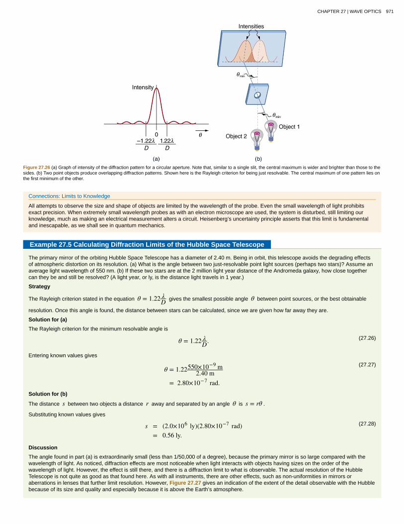
Figure 27.26 (a) Graph of intensity of the diffraction pattern for a circular aperture. Note that, similar to a single slit, the central maximum is wider and brighter than those to thesides. (b) Two point objects produce overlapping diffraction patterns. Shown here is the Rayleigh criterion for being just resolvable. The central maximum of one pattern lies onthe first minimum of the other.
Connections: Limits to Knowledge
All attempts to observe the size and shape of objects are limited by the wavelength of the probe. Even the small wavelength of light prohibitsexact precision. When extremely small wavelength probes as with an electron microscope are used, the system is disturbed, still limiting ourknowledge, much as making an electrical measurement alters a circuit. Heisenberg’s uncertainty principle asserts that this limit is fundamentaland inescapable, as we shall see in quantum mechanics.
Example 27.5 Calculating Diffraction Limits of the Hubble Space Telescope
The primary mirror of the orbiting Hubble Space Telescope has a diameter of 2.40 m. Being in orbit, this telescope avoids the degrading effectsof atmospheric distortion on its resolution. (a) What is the angle between two just-resolvable point light sources (perhaps two stars)? Assume anaverage light wavelength of 550 nm. (b) If these two stars are at the 2 million light year distance of the Andromeda galaxy, how close togethercan they be and still be resolved? (A light year, or ly, is the distance light travels in 1 year.)
Strategy
The Rayleigh criterion stated in the equation θ = 1.22 λD gives the smallest possible angle θ between point sources, or the best obtainable
resolution. Once this angle is found, the distance between stars can be calculated, since we are given how far away they are.
Solution for (a)
The Rayleigh criterion for the minimum resolvable angle is
(27.26)θ = 1.22 λD.
Entering known values gives
(27.27)θ = 1.22550×10⁻⁹ m
2.40 m= 2.80×10⁻⁷ rad.
Solution for (b)
The distance s between two objects a distance r away and separated by an angle θ is s = rθ .
Substituting known values gives
(27.28)s = (2.0×10⁶ ly)(2.80×10⁻⁷ rad)= 0.56 ly.
Discussion
The angle found in part (a) is extraordinarily small (less than 1/50,000 of a degree), because the primary mirror is so large compared with thewavelength of light. As noticed, diffraction effects are most noticeable when light interacts with objects having sizes on the order of thewavelength of light. However, the effect is still there, and there is a diffraction limit to what is observable. The actual resolution of the HubbleTelescope is not quite as good as that found here. As with all instruments, there are other effects, such as non-uniformities in mirrors oraberrations in lenses that further limit resolution. However, Figure 27.27 gives an indication of the extent of the detail observable with the Hubblebecause of its size and quality and especially because it is above the Earth’s atmosphere.
CHAPTER 27 | WAVE OPTICS 971

Figure 27.27 These two photographs of the M82 galaxy give an idea of the observable detail using the Hubble Space Telescope compared with that using a ground-based telescope. (a) On the left is a ground-based image. (credit: Ricnun, Wikimedia Commons) (b) The photo on the right was captured by Hubble. (credit: NASA, ESA,and the Hubble Heritage Team (STScI/AURA))
The answer in part (b) indicates that two stars separated by about half a light year can be resolved. The average distance between stars in agalaxy is on the order of 5 light years in the outer parts and about 1 light year near the galactic center. Therefore, the Hubble can resolve most ofthe individual stars in Andromeda galaxy, even though it lies at such a huge distance that its light takes 2 million years for its light to reach us.Figure 27.28 shows another mirror used to observe radio waves from outer space.
Figure 27.28 A 305-m-diameter natural bowl at Arecibo in Puerto Rico is lined with reflective material, making it into a radio telescope. It is the largest curved focusingdish in the world. Although D for Arecibo is much larger than for the Hubble Telescope, it detects much longer wavelength radiation and its diffraction limit is significantlypoorer than Hubble’s. Arecibo is still very useful, because important information is carried by radio waves that is not carried by visible light. (credit: Tatyana Temirbulatova,Flickr)
Diffraction is not only a problem for optical instruments but also for the electromagnetic radiation itself. Any beam of light having a finite diameter D
and a wavelength λ exhibits diffraction spreading. The beam spreads out with an angle θ given by the equation θ = 1.22 λD . Take, for example, a
laser beam made of rays as parallel as possible (angles between rays as close to θ = 0º as possible) instead spreads out at an angle
θ = 1.22 λ / D , where D is the diameter of the beam and λ is its wavelength. This spreading is impossible to observe for a flashlight, because itsbeam is not very parallel to start with. However, for long-distance transmission of laser beams or microwave signals, diffraction spreading can besignificant (see Figure 27.29). To avoid this, we can increase D . This is done for laser light sent to the Moon to measure its distance from the Earth.
The laser beam is expanded through a telescope to make D much larger and θ smaller.
Figure 27.29 The beam produced by this microwave transmission antenna will spread out at a minimum angle θ = 1.22 λ / D due to diffraction. It is impossible to producea near-parallel beam, because the beam has a limited diameter.
In most biology laboratories, resolution is presented when the use of the microscope is introduced. The ability of a lens to produce sharp images oftwo closely spaced point objects is called resolution. The smaller the distance x by which two objects can be separated and still be seen as distinct,the greater the resolution. The resolving power of a lens is defined as that distance x . An expression for resolving power is obtained from theRayleigh criterion. In Figure 27.30(a) we have two point objects separated by a distance x . According to the Rayleigh criterion, resolution is possiblewhen the minimum angular separation is
(27.29)θ = 1.22 λD = x
d ,
972 CHAPTER 27 | WAVE OPTICS
This content is available for free at http://cnx.org/content/col11406/1.7
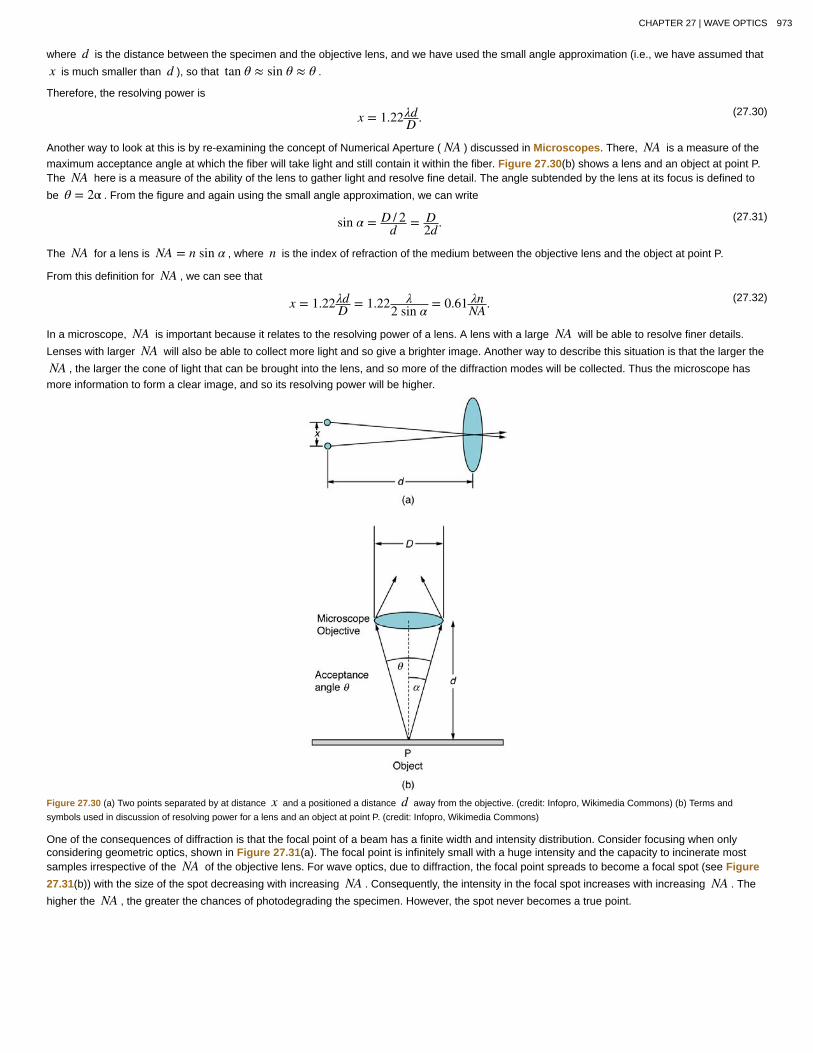
where d is the distance between the specimen and the objective lens, and we have used the small angle approximation (i.e., we have assumed that
x is much smaller than d ), so that tan θ ≈ sin θ ≈ θ .
Therefore, the resolving power is
(27.30)x = 1.22λdD .
Another way to look at this is by re-examining the concept of Numerical Aperture ( NA ) discussed in Microscopes. There, NA is a measure of themaximum acceptance angle at which the fiber will take light and still contain it within the fiber. Figure 27.30(b) shows a lens and an object at point P.The NA here is a measure of the ability of the lens to gather light and resolve fine detail. The angle subtended by the lens at its focus is defined to
be θ = 2α . From the figure and again using the small angle approximation, we can write
(27.31)sin α = D / 2d = D
2d .
The NA for a lens is NA = n sin α , where n is the index of refraction of the medium between the objective lens and the object at point P.
From this definition for NA , we can see that
(27.32)x = 1.22λdD = 1.22 λ
2 sin α = 0.61 λnNA .
In a microscope, NA is important because it relates to the resolving power of a lens. A lens with a large NA will be able to resolve finer details.
Lenses with larger NA will also be able to collect more light and so give a brighter image. Another way to describe this situation is that the larger the
NA , the larger the cone of light that can be brought into the lens, and so more of the diffraction modes will be collected. Thus the microscope hasmore information to form a clear image, and so its resolving power will be higher.
Figure 27.30 (a) Two points separated by at distance x and a positioned a distance d away from the objective. (credit: Infopro, Wikimedia Commons) (b) Terms andsymbols used in discussion of resolving power for a lens and an object at point P. (credit: Infopro, Wikimedia Commons)
One of the consequences of diffraction is that the focal point of a beam has a finite width and intensity distribution. Consider focusing when onlyconsidering geometric optics, shown in Figure 27.31(a). The focal point is infinitely small with a huge intensity and the capacity to incinerate mostsamples irrespective of the NA of the objective lens. For wave optics, due to diffraction, the focal point spreads to become a focal spot (see Figure27.31(b)) with the size of the spot decreasing with increasing NA . Consequently, the intensity in the focal spot increases with increasing NA . The
higher the NA , the greater the chances of photodegrading the specimen. However, the spot never becomes a true point.
CHAPTER 27 | WAVE OPTICS 973

Figure 27.31 (a) In geometric optics, the focus is a point, but it is not physically possible to produce such a point because it implies infinite intensity. (b) In wave optics, thefocus is an extended region.
27.7 Thin Film InterferenceThe bright colors seen in an oil slick floating on water or in a sunlit soap bubble are caused by interference. The brightest colors are those thatinterfere constructively. This interference is between light reflected from different surfaces of a thin film; thus, the effect is known as thin filminterference. As noticed before, interference effects are most prominent when light interacts with something having a size similar to its wavelength. Athin film is one having a thickness t smaller than a few times the wavelength of light, λ . Since color is associated indirectly with λ and since all
interference depends in some way on the ratio of λ to the size of the object involved, we should expect to see different colors for differentthicknesses of a film, as in Figure 27.32.
Figure 27.32 These soap bubbles exhibit brilliant colors when exposed to sunlight. (credit: Scott Robinson, Flickr)
What causes thin film interference? Figure 27.33 shows how light reflected from the top and bottom surfaces of a film can interfere. Incident light isonly partially reflected from the top surface of the film (ray 1). The remainder enters the film and is itself partially reflected from the bottom surface.Part of the light reflected from the bottom surface can emerge from the top of the film (ray 2) and interfere with light reflected from the top (ray 1).Since the ray that enters the film travels a greater distance, it may be in or out of phase with the ray reflected from the top. However, consider for amoment, again, the bubbles in Figure 27.32. The bubbles are darkest where they are thinnest. Furthermore, if you observe a soap bubble carefully,you will note it gets dark at the point where it breaks. For very thin films, the difference in path lengths of ray 1 and ray 2 in Figure 27.33 is negligible;so why should they interfere destructively and not constructively? The answer is that a phase change can occur upon reflection. The rule is asfollows:
When light reflects from a medium having an index of refraction greater than that of the medium in which it is traveling, a 180º phasechange (or a λ / 2 shift) occurs.
974 CHAPTER 27 | WAVE OPTICS
This content is available for free at http://cnx.org/content/col11406/1.7

Figure 27.33 Light striking a thin film is partially reflected (ray 1) and partially refracted at the top surface. The refracted ray is partially reflected at the bottom surface andemerges as ray 2. These rays will interfere in a way that depends on the thickness of the film and the indices of refraction of the various media.
If the film in Figure 27.33 is a soap bubble (essentially water with air on both sides), then there is a λ / 2 shift for ray 1 and none for ray 2. Thus,when the film is very thin, the path length difference between the two rays is negligible, they are exactly out of phase, and destructive interference willoccur at all wavelengths and so the soap bubble will be dark here.
The thickness of the film relative to the wavelength of light is the other crucial factor in thin film interference. Ray 2 in Figure 27.33 travels a greaterdistance than ray 1. For light incident perpendicular to the surface, ray 2 travels a distance approximately 2t farther than ray 1. When this distance is
an integral or half-integral multiple of the wavelength in the medium ( λn = λ / n , where λ is the wavelength in vacuum and n is the index of
refraction), constructive or destructive interference occurs, depending also on whether there is a phase change in either ray.
Example 27.6 Calculating Non-reflective Lens Coating Using Thin Film Interference
Sophisticated cameras use a series of several lenses. Light can reflect from the surfaces of these various lenses and degrade image clarity. Tolimit these reflections, lenses are coated with a thin layer of magnesium fluoride that causes destructive thin film interference. What is thethinnest this film can be, if its index of refraction is 1.38 and it is designed to limit the reflection of 550-nm light, normally the most intense visiblewavelength? The index of refraction of glass is 1.52.
Strategy
Refer to Figure 27.33 and use n1 = 100 for air, n2 = 1.38 , and n3 = 1.52 . Both ray 1 and ray 2 will have a λ / 2 shift upon reflection.
Thus, to obtain destructive interference, ray 2 will need to travel a half wavelength farther than ray 1. For rays incident perpendicularly, the pathlength difference is 2t .
Solution
To obtain destructive interference here,
(27.33)2t =
λn22 ,
where λn2 is the wavelength in the film and is given by λn2 = λn2
.
Thus,
(27.34)2t = λ / n2
2 .
Solving for t and entering known values yields
(27.35)t = λ / n2
4 = (550 nm) / 1.384
= 99.6 nm.Discussion
CHAPTER 27 | WAVE OPTICS 975

Films such as the one in this example are most effective in producing destructive interference when the thinnest layer is used, since light over abroader range of incident angles will be reduced in intensity. These films are called non-reflective coatings; this is only an approximately correctdescription, though, since other wavelengths will only be partially cancelled. Non-reflective coatings are used in car windows and sunglasses.
Thin film interference is most constructive or most destructive when the path length difference for the two rays is an integral or half-integralwavelength, respectively. That is, for rays incident perpendicularly, 2t = λn, 2λn , 3λn , … or 2t = λn / 2, 3λn / 2, 5λn / 2, … . To know whether
interference is constructive or destructive, you must also determine if there is a phase change upon reflection. Thin film interference thus depends onfilm thickness, the wavelength of light, and the refractive indices. For white light incident on a film that varies in thickness, you will observe rainbowcolors of constructive interference for various wavelengths as the thickness varies.
Example 27.7 Soap Bubbles: More Than One Thickness can be Constructive
(a) What are the three smallest thicknesses of a soap bubble that produce constructive interference for red light with a wavelength of 650 nm?The index of refraction of soap is taken to be the same as that of water. (b) What three smallest thicknesses will give destructive interference?
Strategy and Concept
Use Figure 27.33 to visualize the bubble. Note that n1 = n3 = 1.00 for air, and n2 = 1.333 for soap (equivalent to water). There is a λ / 2shift for ray 1 reflected from the top surface of the bubble, and no shift for ray 2 reflected from the bottom surface. To get constructiveinterference, then, the path length difference ( 2t ) must be a half-integral multiple of the wavelength—the first three being λn / 2, 3λn / 2 , and
5λn / 2 . To get destructive interference, the path length difference must be an integral multiple of the wavelength—the first three being 0, λn ,
and 2λn .
Solution for (a)
Constructive interference occurs here when
(27.36)2tc = λn2 , 3λn
2 , 5λn2 , … .
The smallest constructive thickness tc thus is
(27.37)tc = λn4 = λ / n
4 = (650 nm) / 1.3334
= 122 nm.
The next thickness that gives constructive interference is t′c = 3λn / 4 , so that
(27.38)t′c = 366 nm.
Finally, the third thickness producing constructive interference is t′′c ≤ 5λn / 4 , so that
(27.39)t′′c = 610 nm.
Solution for (b)
For destructive interference, the path length difference here is an integral multiple of the wavelength. The first occurs for zero thickness, sincethere is a phase change at the top surface. That is,
(27.40)td = 0.
The first non-zero thickness producing destructive interference is
(27.41)2t′d = λn.
Substituting known values gives
(27.42)t′d = λ2 = λ / n
2 = (650 nm) / 1.3332
= 244 nm.
Finally, the third destructive thickness is 2t′′d = 2λn , so that
(27.43)t′′d = λn = λn = 650 nm
1.333= 488 nm.
Discussion
If the bubble was illuminated with pure red light, we would see bright and dark bands at very uniform increases in thickness. First would be adark band at 0 thickness, then bright at 122 nm thickness, then dark at 244 nm, bright at 366 nm, dark at 488 nm, and bright at 610 nm. If thebubble varied smoothly in thickness, like a smooth wedge, then the bands would be evenly spaced.
976 CHAPTER 27 | WAVE OPTICS
This content is available for free at http://cnx.org/content/col11406/1.7

Another example of thin film interference can be seen when microscope slides are separated (see Figure 27.34). The slides are very flat, so that thewedge of air between them increases in thickness very uniformly. A phase change occurs at the second surface but not the first, and so there is adark band where the slides touch. The rainbow colors of constructive interference repeat, going from violet to red again and again as the distancebetween the slides increases. As the layer of air increases, the bands become more difficult to see, because slight changes in incident angle havegreater effects on path length differences. If pure-wavelength light instead of white light is used, then bright and dark bands are obtained rather thanrepeating rainbow colors.
Figure 27.34 (a) The rainbow color bands are produced by thin film interference in the air between the two glass slides. (b) Schematic of the paths taken by rays in the wedgeof air between the slides.
An important application of thin film interference is found in the manufacturing of optical instruments. A lens or mirror can be compared with a masteras it is being ground, allowing it to be shaped to an accuracy of less than a wavelength over its entire surface. Figure 27.35 illustrates thephenomenon called Newton’s rings, which occurs when the plane surfaces of two lenses are placed together. (The circular bands are called Newton’srings because Isaac Newton described them and their use in detail. Newton did not discover them; Robert Hooke did, and Newton did not believethey were due to the wave character of light.) Each successive ring of a given color indicates an increase of only one wavelength in the distancebetween the lens and the blank, so that great precision can be obtained. Once the lens is perfect, there will be no rings.
Figure 27.35 “Newton's rings” interference fringes are produced when two plano-convex lenses are placed together with their plane surfaces in contact. The rings are createdby interference between the light reflected off the two surfaces as a result of a slight gap between them, indicating that these surfaces are not precisely plane but are slightlyconvex. (credit: Ulf Seifert, Wikimedia Commons)
The wings of certain moths and butterflies have nearly iridescent colors due to thin film interference. In addition to pigmentation, the wing’s color isaffected greatly by constructive interference of certain wavelengths reflected from its film-coated surface. Car manufacturers are offering special paintjobs that use thin film interference to produce colors that change with angle. This expensive option is based on variation of thin film path lengthdifferences with angle. Security features on credit cards, banknotes, driving licenses and similar items prone to forgery use thin film interference,diffraction gratings, or holograms. Australia led the way with dollar bills printed on polymer with a diffraction grating security feature making thecurrency difficult to forge. Other countries such as New Zealand and Taiwan are using similar technologies, while the United States currency includesa thin film interference effect.
Making Connections: Take-Home Experiment—Thin Film Interference
One feature of thin film interference and diffraction gratings is that the pattern shifts as you change the angle at which you look or move yourhead. Find examples of thin film interference and gratings around you. Explain how the patterns change for each specific example. Findexamples where the thickness changes giving rise to changing colors. If you can find two microscope slides, then try observing the effect shownin Figure 27.34. Try separating one end of the two slides with a hair or maybe a thin piece of paper and observe the effect.
Problem-Solving Strategies for Wave OpticsStep 1. Examine the situation to determine that interference is involved. Identify whether slits or thin film interference are considered in the problem.
Step 2. If slits are involved, note that diffraction gratings and double slits produce very similar interference patterns, but that gratings have narrower(sharper) maxima. Single slit patterns are characterized by a large central maximum and smaller maxima to the sides.
Step 3. If thin film interference is involved, take note of the path length difference between the two rays that interfere. Be certain to use thewavelength in the medium involved, since it differs from the wavelength in vacuum. Note also that there is an additional λ / 2 phase shift when lightreflects from a medium with a greater index of refraction.
Step 4. Identify exactly what needs to be determined in the problem (identify the unknowns). A written list is useful. Draw a diagram of the situation.Labeling the diagram is useful.
Step 5. Make a list of what is given or can be inferred from the problem as stated (identify the knowns).
CHAPTER 27 | WAVE OPTICS 977

Step 6. Solve the appropriate equation for the quantity to be determined (the unknown), and enter the knowns. Slits, gratings, and the Rayleigh limitinvolve equations.
Step 7. For thin film interference, you will have constructive interference for a total shift that is an integral number of wavelengths. You will havedestructive interference for a total shift of a half-integral number of wavelengths. Always keep in mind that crest to crest is constructive whereas crestto trough is destructive.
Step 8. Check to see if the answer is reasonable: Does it make sense? Angles in interference patterns cannot be greater than 90º , for example.
27.8 PolarizationPolaroid sunglasses are familiar to most of us. They have a special ability to cut the glare of light reflected from water or glass (see Figure 27.36).Polaroids have this ability because of a wave characteristic of light called polarization. What is polarization? How is it produced? What are some of itsuses? The answers to these questions are related to the wave character of light.
Figure 27.36 These two photographs of a river show the effect of a polarizing filter in reducing glare in light reflected from the surface of water. Part (b) of this figure was takenwith a polarizing filter and part (a) was not. As a result, the reflection of clouds and sky observed in part (a) is not observed in part (b). Polarizing sunglasses are particularlyuseful on snow and water. (credit: Amithshs, Wikimedia Commons)
Light is one type of electromagnetic (EM) wave. As noted earlier, EM waves are transverse waves consisting of varying electric and magnetic fieldsthat oscillate perpendicular to the direction of propagation (see Figure 27.37). There are specific directions for the oscillations of the electric andmagnetic fields. Polarization is the attribute that a wave’s oscillations have a definite direction relative to the direction of propagation of the wave.(This is not the same type of polarization as that discussed for the separation of charges.) Waves having such a direction are said to be polarized.For an EM wave, we define the direction of polarization to be the direction parallel to the electric field. Thus we can think of the electric field arrowsas showing the direction of polarization, as in Figure 27.37.
Figure 27.37 An EM wave, such as light, is a transverse wave. The electric and magnetic fields are perpendicular to the direction of propagation.
To examine this further, consider the transverse waves in the ropes shown in Figure 27.38. The oscillations in one rope are in a vertical plane andare said to be vertically polarized. Those in the other rope are in a horizontal plane and are horizontally polarized. If a vertical slit is placed on thefirst rope, the waves pass through. However, a vertical slit blocks the horizontally polarized waves. For EM waves, the direction of the electric field isanalogous to the disturbances on the ropes.
Figure 27.38 The transverse oscillations in one rope are in a vertical plane, and those in the other rope are in a horizontal plane. The first is said to be vertically polarized, andthe other is said to be horizontally polarized. Vertical slits pass vertically polarized waves and block horizontally polarized waves.
The Sun and many other light sources produce waves that are randomly polarized (see Figure 27.39). Such light is said to be unpolarized becauseit is composed of many waves with all possible directions of polarization. Polaroid materials, invented by the founder of Polaroid Corporation, Edwin
978 CHAPTER 27 | WAVE OPTICS
This content is available for free at http://cnx.org/content/col11406/1.7

Land, act as a polarizing slit for light, allowing only polarization in one direction to pass through. Polarizing filters are composed of long moleculesaligned in one direction. Thinking of the molecules as many slits, analogous to those for the oscillating ropes, we can understand why only light with aspecific polarization can get through. The axis of a polarizing filter is the direction along which the filter passes the electric field of an EM wave (seeFigure 27.40).
Figure 27.39 The slender arrow represents a ray of unpolarized light. The bold arrows represent the direction of polarization of the individual waves composing the ray. Sincethe light is unpolarized, the arrows point in all directions.
Figure 27.40 A polarizing filter has a polarization axis that acts as a slit passing through electric fields parallel to its direction. The direction of polarization of an EM wave isdefined to be the direction of its electric field.
Figure 27.41 shows the effect of two polarizing filters on originally unpolarized light. The first filter polarizes the light along its axis. When the axes ofthe first and second filters are aligned (parallel), then all of the polarized light passed by the first filter is also passed by the second. If the secondpolarizing filter is rotated, only the component of the light parallel to the second filter’s axis is passed. When the axes are perpendicular, no light ispassed by the second.
Only the component of the EM wave parallel to the axis of a filter is passed. Let us call the angle between the direction of polarization and the axis ofa filter θ . If the electric field has an amplitude E , then the transmitted part of the wave has an amplitude E cos θ (see Figure 27.42). Since the
intensity of a wave is proportional to its amplitude squared, the intensity I of the transmitted wave is related to the incident wave by
(27.44)I = I0 cos2 θ,
where I0 is the intensity of the polarized wave before passing through the filter. (The above equation is known as Malus’s law.)
CHAPTER 27 | WAVE OPTICS 979

Figure 27.41 The effect of rotating two polarizing filters, where the first polarizes the light. (a) All of the polarized light is passed by the second polarizing filter, because its axisis parallel to the first. (b) As the second is rotated, only part of the light is passed. (c) When the second is perpendicular to the first, no light is passed. (d) In this photograph, apolarizing filter is placed above two others. Its axis is perpendicular to the filter on the right (dark area) and parallel to the filter on the left (lighter area). (credit: P.P. Urone)
Figure 27.42 A polarizing filter transmits only the component of the wave parallel to its axis, E cos θ , reducing the intensity of any light not polarized parallel to its axis.
Example 27.8 Calculating Intensity Reduction by a Polarizing Filter
What angle is needed between the direction of polarized light and the axis of a polarizing filter to reduce its intensity by 90.0% ?
Strategy
When the intensity is reduced by 90.0% , it is 10.0% or 0.100 times its original value. That is, I = 0.100I0 . Using this information, the
equation I = I0 cos2 θ can be used to solve for the needed angle.
Solution
Solving the equation I = I0 cos2 θ for cos θ and substituting with the relationship between I and I0 gives
(27.45)cos θ = I
I0= 0.100I0
I0= 0.3162.
Solving for θ yields
(27.46)θ = cos−1 0.3162 = 71.6º.Discussion
A fairly large angle between the direction of polarization and the filter axis is needed to reduce the intensity to 10.0% of its original value. This
seems reasonable based on experimenting with polarizing films. It is interesting that, at an angle of 45º , the intensity is reduced to 50% of its
original value (as you will show in this section’s Problems & Exercises). Note that 71.6º is 18.4º from reducing the intensity to zero, and that at
an angle of 18.4º the intensity is reduced to 90.0% of its original value (as you will also show in Problems & Exercises), giving evidence ofsymmetry.
Polarization by ReflectionBy now you can probably guess that Polaroid sunglasses cut the glare in reflected light because that light is polarized. You can check this for yourselfby holding Polaroid sunglasses in front of you and rotating them while looking at light reflected from water or glass. As you rotate the sunglasses, you
980 CHAPTER 27 | WAVE OPTICS
This content is available for free at http://cnx.org/content/col11406/1.7

will notice the light gets bright and dim, but not completely black. This implies the reflected light is partially polarized and cannot be completelyblocked by a polarizing filter.
Figure 27.43 illustrates what happens when unpolarized light is reflected from a surface. Vertically polarized light is preferentially refracted at thesurface, so that the reflected light is left more horizontally polarized. The reasons for this phenomenon are beyond the scope of this text, but aconvenient mnemonic for remembering this is to imagine the polarization direction to be like an arrow. Vertical polarization would be like an arrowperpendicular to the surface and would be more likely to stick and not be reflected. Horizontal polarization is like an arrow bouncing on its side andwould be more likely to be reflected. Sunglasses with vertical axes would then block more reflected light than unpolarized light from other sources.
Figure 27.43 Polarization by reflection. Unpolarized light has equal amounts of vertical and horizontal polarization. After interaction with a surface, the vertical components arepreferentially absorbed or refracted, leaving the reflected light more horizontally polarized. This is akin to arrows striking on their sides bouncing off, whereas arrows striking ontheir tips go into the surface.
Since the part of the light that is not reflected is refracted, the amount of polarization depends on the indices of refraction of the media involved. It canbe shown that reflected light is completely polarized at a angle of reflection θb , given by
(27.47)tan θb = n2n1
,
where n1 is the medium in which the incident and reflected light travel and n2 is the index of refraction of the medium that forms the interface that
reflects the light. This equation is known as Brewster’s law, and θb is known as Brewster’s angle, named after the 19th-century Scottish physicist
who discovered them.
Things Great and Small: Atomic Explanation of Polarizing Filters
Polarizing filters have a polarization axis that acts as a slit. This slit passes electromagnetic waves (often visible light) that have an electric fieldparallel to the axis. This is accomplished with long molecules aligned perpendicular to the axis as shown in Figure 27.44.
Figure 27.44 Long molecules are aligned perpendicular to the axis of a polarizing filter. The component of the electric field in an EM wave perpendicular to thesemolecules passes through the filter, while the component parallel to the molecules is absorbed.
Figure 27.45 illustrates how the component of the electric field parallel to the long molecules is absorbed. An electromagnetic wave is composedof oscillating electric and magnetic fields. The electric field is strong compared with the magnetic field and is more effective in exerting force oncharges in the molecules. The most affected charged particles are the electrons in the molecules, since electron masses are small. If theelectron is forced to oscillate, it can absorb energy from the EM wave. This reduces the fields in the wave and, hence, reduces its intensity. Inlong molecules, electrons can more easily oscillate parallel to the molecule than in the perpendicular direction. The electrons are bound to the
CHAPTER 27 | WAVE OPTICS 981

molecule and are more restricted in their movement perpendicular to the molecule. Thus, the electrons can absorb EM waves that have acomponent of their electric field parallel to the molecule. The electrons are much less responsive to electric fields perpendicular to the moleculeand will allow those fields to pass. Thus the axis of the polarizing filter is perpendicular to the length of the molecule.
Figure 27.45 Artist’s conception of an electron in a long molecule oscillating parallel to the molecule. The oscillation of the electron absorbs energy and reduces theintensity of the component of the EM wave that is parallel to the molecule.
Example 27.9 Calculating Polarization by Reflection
(a) At what angle will light traveling in air be completely polarized horizontally when reflected from water? (b) From glass?
Strategy
All we need to solve these problems are the indices of refraction. Air has n1 = 1.00, water has n2 = 1.333, and crown glass has
n′2 = 1.520 . The equation tan θb = n2n1
can be directly applied to find θb in each case.
Solution for (a)
Putting the known quantities into the equation
(27.48)tan θb = n2n1
gives
(27.49)tan θb = n2n1
= 1.3331.00 = 1.333.
Solving for the angle θb yields
(27.50)θb = tan−1 1.333 = 53.1º.
Solution for (b)
Similarly, for crown glass and air,
(27.51)tan θ′b = n′2
n1= 1.520
1.00 = 1.52.
Thus,
(27.52)θ′b = tan−1 1.52 = 56.7º.
Discussion
Light reflected at these angles could be completely blocked by a good polarizing filter held with its axis vertical. Brewster’s angle for water and airare similar to those for glass and air, so that sunglasses are equally effective for light reflected from either water or glass under similarcircumstances. Light not reflected is refracted into these media. So at an incident angle equal to Brewster’s angle, the refracted light will be
982 CHAPTER 27 | WAVE OPTICS
This content is available for free at http://cnx.org/content/col11406/1.7

slightly polarized vertically. It will not be completely polarized vertically, because only a small fraction of the incident light is reflected, and so asignificant amount of horizontally polarized light is refracted.
Polarization by ScatteringIf you hold your Polaroid sunglasses in front of you and rotate them while looking at blue sky, you will see the sky get bright and dim. This is a clearindication that light scattered by air is partially polarized. Figure 27.46 helps illustrate how this happens. Since light is a transverse EM wave, itvibrates the electrons of air molecules perpendicular to the direction it is traveling. The electrons then radiate like small antennae. Since they areoscillating perpendicular to the direction of the light ray, they produce EM radiation that is polarized perpendicular to the direction of the ray. Whenviewing the light along a line perpendicular to the original ray, as in Figure 27.46, there can be no polarization in the scattered light parallel to theoriginal ray, because that would require the original ray to be a longitudinal wave. Along other directions, a component of the other polarization can beprojected along the line of sight, and the scattered light will only be partially polarized. Furthermore, multiple scattering can bring light to your eyesfrom other directions and can contain different polarizations.
Figure 27.46 Polarization by scattering. Unpolarized light scattering from air molecules shakes their electrons perpendicular to the direction of the original ray. The scatteredlight therefore has a polarization perpendicular to the original direction and none parallel to the original direction.
Photographs of the sky can be darkened by polarizing filters, a trick used by many photographers to make clouds brighter by contrast. Scatteringfrom other particles, such as smoke or dust, can also polarize light. Detecting polarization in scattered EM waves can be a useful analytical tool indetermining the scattering source.
There is a range of optical effects used in sunglasses. Besides being Polaroid, other sunglasses have colored pigments embedded in them, whileothers use non-reflective or even reflective coatings. A recent development is photochromic lenses, which darken in the sunlight and become clearindoors. Photochromic lenses are embedded with organic microcrystalline molecules that change their properties when exposed to UV in sunlight, butbecome clear in artificial lighting with no UV.
Take-Home Experiment: Polarization
Find Polaroid sunglasses and rotate one while holding the other still and look at different surfaces and objects. Explain your observations. Whatis the difference in angle from when you see a maximum intensity to when you see a minimum intensity? Find a reflective glass surface and dothe same. At what angle does the glass need to be oriented to give minimum glare?
Liquid Crystals and Other Polarization Effects in MaterialsWhile you are undoubtedly aware of liquid crystal displays (LCDs) found in watches, calculators, computer screens, cellphones, flat screentelevisions, and other myriad places, you may not be aware that they are based on polarization. Liquid crystals are so named because theirmolecules can be aligned even though they are in a liquid. Liquid crystals have the property that they can rotate the polarization of light passingthrough them by 90º . Furthermore, this property can be turned off by the application of a voltage, as illustrated in Figure 27.47. It is possible tomanipulate this characteristic quickly and in small well-defined regions to create the contrast patterns we see in so many LCD devices.
In flat screen LCD televisions, there is a large light at the back of the TV. The light travels to the front screen through millions of tiny units called pixels(picture elements). One of these is shown in Figure 27.47 (a) and (b). Each unit has three cells, with red, blue, or green filters, each controlledindependently. When the voltage across a liquid crystal is switched off, the liquid crystal passes the light through the particular filter. One can vary thepicture contrast by varying the strength of the voltage applied to the liquid crystal.
CHAPTER 27 | WAVE OPTICS 983

Figure 27.47 (a) Polarized light is rotated 90º by a liquid crystal and then passed by a polarizing filter that has its axis perpendicular to the original polarization direction. (b)When a voltage is applied to the liquid crystal, the polarized light is not rotated and is blocked by the filter, making the region dark in comparison with its surroundings. (c) LCDscan be made color specific, small, and fast enough to use in laptop computers and TVs. (credit: Jon Sullivan)
Many crystals and solutions rotate the plane of polarization of light passing through them. Such substances are said to be optically active. Examplesinclude sugar water, insulin, and collagen (see Figure 27.48). In addition to depending on the type of substance, the amount and direction of rotationdepends on a number of factors. Among these is the concentration of the substance, the distance the light travels through it, and the wavelength oflight. Optical activity is due to the asymmetric shape of molecules in the substance, such as being helical. Measurements of the rotation of polarizedlight passing through substances can thus be used to measure concentrations, a standard technique for sugars. It can also give information on theshapes of molecules, such as proteins, and factors that affect their shapes, such as temperature and pH.
Figure 27.48 Optical activity is the ability of some substances to rotate the plane of polarization of light passing through them. The rotation is detected with a polarizing filter oranalyzer.
Glass and plastic become optically active when stressed; the greater the stress, the greater the effect. Optical stress analysis on complicated shapescan be performed by making plastic models of them and observing them through crossed filters, as seen in Figure 27.49. It is apparent that the effectdepends on wavelength as well as stress. The wavelength dependence is sometimes also used for artistic purposes.
984 CHAPTER 27 | WAVE OPTICS
This content is available for free at http://cnx.org/content/col11406/1.7

Figure 27.49 Optical stress analysis of a plastic lens placed between crossed polarizers. (credit: Infopro, Wikimedia Commons)
Another interesting phenomenon associated with polarized light is the ability of some crystals to split an unpolarized beam of light into two. Suchcrystals are said to be birefringent (see Figure 27.50). Each of the separated rays has a specific polarization. One behaves normally and is calledthe ordinary ray, whereas the other does not obey Snell’s law and is called the extraordinary ray. Birefringent crystals can be used to producepolarized beams from unpolarized light. Some birefringent materials preferentially absorb one of the polarizations. These materials are called dichroicand can produce polarization by this preferential absorption. This is fundamentally how polarizing filters and other polarizers work. The interestedreader is invited to further pursue the numerous properties of materials related to polarization.
Figure 27.50 Birefringent materials, such as the common mineral calcite, split unpolarized beams of light into two. The ordinary ray behaves as expected, but the extraordinaryray does not obey Snell’s law.
27.9 *Extended Topic* Microscopy Enhanced by the Wave Characteristics of LightPhysics research underpins the advancement of developments in microscopy. As we gain knowledge of the wave nature of electromagnetic wavesand methods to analyze and interpret signals, new microscopes that enable us to “see” more are being developed. It is the evolution and newergeneration of microscopes that are described in this section.
The use of microscopes (microscopy) to observe small details is limited by the wave nature of light. Owing to the fact that light diffracts significantlyaround small objects, it becomes impossible to observe details significantly smaller than the wavelength of light. One rule of thumb has it that alldetails smaller than about λ are difficult to observe. Radar, for example, can detect the size of an aircraft, but not its individual rivets, since thewavelength of most radar is several centimeters or greater. Similarly, visible light cannot detect individual atoms, since atoms are about 0.1 nm in sizeand visible wavelengths range from 380 to 760 nm. Ironically, special techniques used to obtain the best possible resolution with microscopes takeadvantage of the same wave characteristics of light that ultimately limit the detail.
Making Connections: Waves
All attempts to observe the size and shape of objects are limited by the wavelength of the probe. Sonar and medical ultrasound are limited by thewavelength of sound they employ. We shall see that this is also true in electron microscopy, since electrons have a wavelength. Heisenberg’suncertainty principle asserts that this limit is fundamental and inescapable, as we shall see in quantum mechanics.
The most obvious method of obtaining better detail is to utilize shorter wavelengths. Ultraviolet (UV) microscopes have been constructed withspecial lenses that transmit UV rays and utilize photographic or electronic techniques to record images. The shorter UV wavelengths allow somewhatgreater detail to be observed, but drawbacks, such as the hazard of UV to living tissue and the need for special detection devices and lenses (whichtend to be dispersive in the UV), severely limit the use of UV microscopes. Elsewhere, we will explore practical uses of very short wavelength EMwaves, such as x rays, and other short-wavelength probes, such as electrons in electron microscopes, to detect small details.
Another difficulty in microscopy is the fact that many microscopic objects do not absorb much of the light passing through them. The lack of contrastmakes image interpretation very difficult. Contrast is the difference in intensity between objects and the background on which they are observed.Stains (such as dyes, fluorophores, etc.) are commonly employed to enhance contrast, but these tend to be application specific. More general waveinterference techniques can be used to produce contrast. Figure 27.51 shows the passage of light through a sample. Since the indices of refractiondiffer, the number of wavelengths in the paths differs. Light emerging from the object is thus out of phase with light from the background and willinterfere differently, producing enhanced contrast, especially if the light is coherent and monochromatic—as in laser light.
CHAPTER 27 | WAVE OPTICS 985

Figure 27.51 Light rays passing through a sample under a microscope will emerge with different phases depending on their paths. The object shown has a greater index ofrefraction than the background, and so the wavelength decreases as the ray passes through it. Superimposing these rays produces interference that varies with path,enhancing contrast between the object and background.
Interference microscopes enhance contrast between objects and background by superimposing a reference beam of light upon the light emergingfrom the sample. Since light from the background and objects differ in phase, there will be different amounts of constructive and destructiveinterference, producing the desired contrast in final intensity. Figure 27.52 shows schematically how this is done. Parallel rays of light from a sourceare split into two beams by a half-silvered mirror. These beams are called the object and reference beams. Each beam passes through identicaloptical elements, except that the object beam passes through the object we wish to observe microscopically. The light beams are recombined byanother half-silvered mirror and interfere. Since the light rays passing through different parts of the object have different phases, interference will besignificantly different and, hence, have greater contrast between them.
Figure 27.52 An interference microscope utilizes interference between the reference and object beam to enhance contrast. The two beams are split by a half-silvered mirror;the object beam is sent through the object, and the reference beam is sent through otherwise identical optical elements. The beams are recombined by another half-silveredmirror, and the interference depends on the various phases emerging from different parts of the object, enhancing contrast.
Another type of microscope utilizing wave interference and differences in phases to enhance contrast is called the phase-contrast microscope.While its principle is the same as the interference microscope, the phase-contrast microscope is simpler to use and construct. Its impact (and theprinciple upon which it is based) was so important that its developer, the Dutch physicist Frits Zernike (1888–1966), was awarded the Nobel Prize in1953. Figure 27.53 shows the basic construction of a phase-contrast microscope. Phase differences between light passing through the object andbackground are produced by passing the rays through different parts of a phase plate (so called because it shifts the phase of the light passingthrough it). These two light rays are superimposed in the image plane, producing contrast due to their interference.
986 CHAPTER 27 | WAVE OPTICS
This content is available for free at http://cnx.org/content/col11406/1.7

Figure 27.53 Simplified construction of a phase-contrast microscope. Phase differences between light passing through the object and background are produced by passing therays through different parts of a phase plate. The light rays are superimposed in the image plane, producing contrast due to their interference.
A polarization microscope also enhances contrast by utilizing a wave characteristic of light. Polarization microscopes are useful for objects that areoptically active or birefringent, particularly if those characteristics vary from place to place in the object. Polarized light is sent through the object andthen observed through a polarizing filter that is perpendicular to the original polarization direction. Nearly transparent objects can then appear withstrong color and in high contrast. Many polarization effects are wavelength dependent, producing color in the processed image. Contrast results fromthe action of the polarizing filter in passing only components parallel to its axis.
Apart from the UV microscope, the variations of microscopy discussed so far in this section are available as attachments to fairly standardmicroscopes or as slight variations. The next level of sophistication is provided by commercial confocal microscopes, which use the extended focalregion shown in Figure 27.31(b) to obtain three-dimensional images rather than two-dimensional images. Here, only a single plane or region of focusis identified; out-of-focus regions above and below this plane are subtracted out by a computer so the image quality is much better. This type ofmicroscope makes use of fluorescence, where a laser provides the excitation light. Laser light passing through a tiny aperture called a pinhole formsan extended focal region within the specimen. The reflected light passes through the objective lens to a second pinhole and the photomultiplierdetector, see Figure 27.54. The second pinhole is the key here and serves to block much of the light from points that are not at the focal point of theobjective lens. The pinhole is conjugate (coupled) to the focal point of the lens. The second pinhole and detector are scanned, allowing reflected lightfrom a small region or section of the extended focal region to be imaged at any one time. The out-of-focus light is excluded. Each image is stored in acomputer, and a full scanned image is generated in a short time. Live cell processes can also be imaged at adequate scanning speeds allowing theimaging of three-dimensional microscopic movement. Confocal microscopy enhances images over conventional optical microscopy, especially forthicker specimens, and so has become quite popular.
The next level of sophistication is provided by microscopes attached to instruments that isolate and detect only a small wavelength band oflight—monochromators and spectral analyzers. Here, the monochromatic light from a laser is scattered from the specimen. This scattered light shiftsup or down as it excites particular energy levels in the sample. The uniqueness of the observed scattered light can give detailed information about thechemical composition of a given spot on the sample with high contrast—like molecular fingerprints. Applications are in materials science,nanotechnology, and the biomedical field. Fine details in biochemical processes over time can even be detected. The ultimate in microscopy is theelectron microscope—to be discussed later. Research is being conducted into the development of new prototype microscopes that can becomecommercially available, providing better diagnostic and research capacities.
CHAPTER 27 | WAVE OPTICS 987

axis of a polarizing filter:
Brewster’s angle:
Brewster’s law:
birefringent:
coherent:
confocal microscopes:
constructive interference for a diffraction grating:
constructive interference for a double slit:
contrast:
destructive interference for a double slit:
destructive interference for a single slit:
diffraction grating:
diffraction:
direction of polarization:
Huygens’s principle:
horizontally polarized:
incoherent:
interference microscopes:
optically active:
order:
Figure 27.54 A confocal microscope provides three-dimensional images using pinholes and the extended depth of focus as described by wave optics. The right pinholeilluminates a tiny region of the sample in the focal plane. In-focus light rays from this tiny region pass through the dichroic mirror and the second pinhole to a detector and acomputer. Out-of-focus light rays are blocked. The pinhole is scanned sideways to form an image of the entire focal plane. The pinhole can then be scanned up and down togather images from different focal planes. The result is a three-dimensional image of the specimen.
Glossarythe direction along which the filter passes the electric field of an EM wave
θb = tan−1⎛⎝n2n1⎞⎠, where n2 is the index of refraction of the medium from which the light is reflected and n1 is the index of
refraction of the medium in which the reflected light travels
tan θb = n2n1
, where n1 is the medium in which the incident and reflected light travel and n2 is the index of refraction of the
medium that forms the interface that reflects the light
crystals that split an unpolarized beam of light into two beams
waves are in phase or have a definite phase relationship
microscopes that use the extended focal region to obtain three-dimensional images rather than two-dimensional images
occurs when the condition d sin θ = mλ (for m = 0, 1, –1, 2, –2, …) is satisfied,
where d is the distance between slits in the grating, λ is the wavelength of light, and m is the order of the maximum
the path length difference must be an integral multiple of the wavelength
the difference in intensity between objects and the background on which they are observed
the path length difference must be a half-integral multiple of the wavelength
occurs when D sin θ = mλ, (for m = 1, –1, 2, –2, 3, …) , where D is the slit width, λ is the
light’s wavelength, θ is the angle relative to the original direction of the light, and m is the order of the minimum
a large number of evenly spaced parallel slits
the bending of a wave around the edges of an opening or an obstacle
the direction parallel to the electric field for EM waves
every point on a wavefront is a source of wavelets that spread out in the forward direction at the same speed as the waveitself. The new wavefront is a line tangent to all of the wavelets
the oscillations are in a horizontal plane
waves have random phase relationships
microscopes that enhance contrast between objects and background by superimposing a reference beam of lightupon the light emerging from the sample
substances that rotate the plane of polarization of light passing through them
the integer m used in the equations for constructive and destructive interference for a double slit
988 CHAPTER 27 | WAVE OPTICS
This content is available for free at http://cnx.org/content/col11406/1.7

phase-contrast microscope:
polarization microscope:
polarization:
polarized:
Rayleigh criterion:
reflected light that is completely polarized:
thin film interference:
ultraviolet (UV) microscopes:
unpolarized:
vertically polarized:
wavelength in a medium:
microscope utilizing wave interference and differences in phases to enhance contrast
microscope that enhances contrast by utilizing a wave characteristic of light, useful for objects that are optically active
the attribute that wave oscillations have a definite direction relative to the direction of propagation of the wave
waves having the electric and magnetic field oscillations in a definite direction
two images are just resolvable when the center of the diffraction pattern of one is directly over the first minimum of thediffraction pattern of the other
light reflected at the angle of reflection θb , known as Brewster’s angle
interference between light reflected from different surfaces of a thin film
microscopes constructed with special lenses that transmit UV rays and utilize photographic or electronictechniques to record images
waves that are randomly polarized
the oscillations are in a vertical plane
λn = λ / n , where λ is the wavelength in vacuum, and n is the index of refraction of the medium
Section Summary
27.1 The Wave Aspect of Light: Interference• Wave optics is the branch of optics that must be used when light interacts with small objects or whenever the wave characteristics of light are
considered.• Wave characteristics are those associated with interference and diffraction.• Visible light is the type of electromagnetic wave to which our eyes respond and has a wavelength in the range of 380 to 760 nm.
• Like all EM waves, the following relationship is valid in vacuum: c = f λ , where c = 3×10⁸ m/s is the speed of light, f is the frequency of
the electromagnetic wave, and λ is its wavelength in vacuum.
• The wavelength λn of light in a medium with index of refraction n is λn = λ / n . Its frequency is the same as in vacuum.
27.2 Huygens's Principle: Diffraction• An accurate technique for determining how and where waves propagate is given by Huygens’s principle: Every point on a wavefront is a source
of wavelets that spread out in the forward direction at the same speed as the wave itself. The new wavefront is a line tangent to all of thewavelets.
• Diffraction is the bending of a wave around the edges of an opening or other obstacle.
27.3 Young’s Double Slit Experiment• Young’s double slit experiment gave definitive proof of the wave character of light.• An interference pattern is obtained by the superposition of light from two slits.• There is constructive interference when d sin θ = mλ (for m = 0, 1, −1, 2, −2, …) , where d is the distance between the slits, θ is the
angle relative to the incident direction, and m is the order of the interference.
• There is destructive interference when d sin θ = ⎛⎝m + 12⎞⎠λ (for m = 0, 1, −1, 2, −2, …) .
27.4 Multiple Slit Diffraction• A diffraction grating is a large collection of evenly spaced parallel slits that produces an interference pattern similar to but sharper than that of a
double slit.• There is constructive interference for a diffraction grating when d sin θ = mλ (for m = 0, 1, –1, 2, –2, …) , where d is the distance
between slits in the grating, λ is the wavelength of light, and m is the order of the maximum.
27.5 Single Slit Diffraction• A single slit produces an interference pattern characterized by a broad central maximum with narrower and dimmer maxima to the sides.• There is destructive interference for a single slit when D sin θ = mλ, (for m = 1, –1, 2, –2, 3, …) , where D is the slit width, λ is the
light’s wavelength, θ is the angle relative to the original direction of the light, and m is the order of the minimum. Note that there is no m = 0minimum.
27.6 Limits of Resolution: The Rayleigh Criterion• Diffraction limits resolution.• For a circular aperture, lens, or mirror, the Rayleigh criterion states that two images are just resolvable when the center of the diffraction pattern
of one is directly over the first minimum of the diffraction pattern of the other.
CHAPTER 27 | WAVE OPTICS 989

• This occurs for two point objects separated by the angle θ = 1.22 λD , where λ is the wavelength of light (or other electromagnetic radiation)
and D is the diameter of the aperture, lens, mirror, etc. This equation also gives the angular spreading of a source of light having a diameter
D .
27.7 Thin Film Interference• Thin film interference occurs between the light reflected from the top and bottom surfaces of a film. In addition to the path length difference,
there can be a phase change.• When light reflects from a medium having an index of refraction greater than that of the medium in which it is traveling, a 180º phase change
(or a λ / 2 shift) occurs.
27.8 Polarization• Polarization is the attribute that wave oscillations have a definite direction relative to the direction of propagation of the wave.• EM waves are transverse waves that may be polarized.• The direction of polarization is defined to be the direction parallel to the electric field of the EM wave.• Unpolarized light is composed of many rays having random polarization directions.• Light can be polarized by passing it through a polarizing filter or other polarizing material. The intensity I of polarized light after passing
through a polarizing filter is I = I0 cos2 θ, where I0 is the original intensity and θ is the angle between the direction of polarization and the
axis of the filter.• Polarization is also produced by reflection.• Brewster’s law states that reflected light will be completely polarized at the angle of reflection θb , known as Brewster’s angle, given by a
statement known as Brewster’s law: tan θb = n2n1
, where n1 is the medium in which the incident and reflected light travel and n2 is the index
of refraction of the medium that forms the interface that reflects the light.• Polarization can also be produced by scattering.• There are a number of types of optically active substances that rotate the direction of polarization of light passing through them.
27.9 *Extended Topic* Microscopy Enhanced by the Wave Characteristics of Light• To improve microscope images, various techniques utilizing the wave characteristics of light have been developed. Many of these enhance
contrast with interference effects.
Conceptual Questions
27.1 The Wave Aspect of Light: Interference1. What type of experimental evidence indicates that light is a wave?
2. Give an example of a wave characteristic of light that is easily observed outside the laboratory.
27.2 Huygens's Principle: Diffraction3. How do wave effects depend on the size of the object with which the wave interacts? For example, why does sound bend around the corner of abuilding while light does not?
4. Under what conditions can light be modeled like a ray? Like a wave?
5. Go outside in the sunlight and observe your shadow. It has fuzzy edges even if you do not. Is this a diffraction effect? Explain.
6. Why does the wavelength of light decrease when it passes from vacuum into a medium? State which attributes change and which stay the sameand, thus, require the wavelength to decrease.
7. Does Huygens’s principle apply to all types of waves?
27.3 Young’s Double Slit Experiment8. Young’s double slit experiment breaks a single light beam into two sources. Would the same pattern be obtained for two independent sources oflight, such as the headlights of a distant car? Explain.
9. Suppose you use the same double slit to perform Young’s double slit experiment in air and then repeat the experiment in water. Do the angles tothe same parts of the interference pattern get larger or smaller? Does the color of the light change? Explain.
10. Is it possible to create a situation in which there is only destructive interference? Explain.
11. Figure 27.55 shows the central part of the interference pattern for a pure wavelength of red light projected onto a double slit. The pattern isactually a combination of single slit and double slit interference. Note that the bright spots are evenly spaced. Is this a double slit or single slitcharacteristic? Note that some of the bright spots are dim on either side of the center. Is this a single slit or double slit characteristic? Which issmaller, the slit width or the separation between slits? Explain your responses.
Figure 27.55 This double slit interference pattern also shows signs of single slit interference. (credit: PASCO)
990 CHAPTER 27 | WAVE OPTICS
This content is available for free at http://cnx.org/content/col11406/1.7

27.4 Multiple Slit Diffraction12. What is the advantage of a diffraction grating over a double slit in dispersing light into a spectrum?
13. What are the advantages of a diffraction grating over a prism in dispersing light for spectral analysis?
14. Can the lines in a diffraction grating be too close together to be useful as a spectroscopic tool for visible light? If so, what type of EM radiationwould the grating be suitable for? Explain.
15. If a beam of white light passes through a diffraction grating with vertical lines, the light is dispersed into rainbow colors on the right and left. If aglass prism disperses white light to the right into a rainbow, how does the sequence of colors compare with that produced on the right by a diffractiongrating?
16. Suppose pure-wavelength light falls on a diffraction grating. What happens to the interference pattern if the same light falls on a grating that hasmore lines per centimeter? What happens to the interference pattern if a longer-wavelength light falls on the same grating? Explain how these twoeffects are consistent in terms of the relationship of wavelength to the distance between slits.
17. Suppose a feather appears green but has no green pigment. Explain in terms of diffraction.
18. It is possible that there is no minimum in the interference pattern of a single slit. Explain why. Is the same true of double slits and diffractiongratings?
27.5 Single Slit Diffraction19. As the width of the slit producing a single-slit diffraction pattern is reduced, how will the diffraction pattern produced change?
27.6 Limits of Resolution: The Rayleigh Criterion20. A beam of light always spreads out. Why can a beam not be created with parallel rays to prevent spreading? Why can lenses, mirrors, orapertures not be used to correct the spreading?
27.7 Thin Film Interference21. What effect does increasing the wedge angle have on the spacing of interference fringes? If the wedge angle is too large, fringes are notobserved. Why?
22. How is the difference in paths taken by two originally in-phase light waves related to whether they interfere constructively or destructively? Howcan this be affected by reflection? By refraction?
23. Is there a phase change in the light reflected from either surface of a contact lens floating on a person’s tear layer? The index of refraction of thelens is about 1.5, and its top surface is dry.
24. In placing a sample on a microscope slide, a glass cover is placed over a water drop on the glass slide. Light incident from above can reflect fromthe top and bottom of the glass cover and from the glass slide below the water drop. At which surfaces will there be a phase change in the reflectedlight?
25. Answer the above question if the fluid between the two pieces of crown glass is carbon disulfide.
26. While contemplating the food value of a slice of ham, you notice a rainbow of color reflected from its moist surface. Explain its origin.
27. An inventor notices that a soap bubble is dark at its thinnest and realizes that destructive interference is taking place for all wavelengths. Howcould she use this knowledge to make a non-reflective coating for lenses that is effective at all wavelengths? That is, what limits would there be onthe index of refraction and thickness of the coating? How might this be impractical?
28. A non-reflective coating like the one described in Example 27.6 works ideally for a single wavelength and for perpendicular incidence. Whathappens for other wavelengths and other incident directions? Be specific.
29. Why is it much more difficult to see interference fringes for light reflected from a thick piece of glass than from a thin film? Would it be easier ifmonochromatic light were used?
27.8 Polarization30. Under what circumstances is the phase of light changed by reflection? Is the phase related to polarization?
31. Can a sound wave in air be polarized? Explain.
32. No light passes through two perfect polarizing filters with perpendicular axes. However, if a third polarizing filter is placed between the originaltwo, some light can pass. Why is this? Under what circumstances does most of the light pass?
33. Explain what happens to the energy carried by light that it is dimmed by passing it through two crossed polarizing filters.
34. When particles scattering light are much smaller than its wavelength, the amount of scattering is proportional to 1 / λ4 . Does this mean there is
more scattering for small λ than large λ ? How does this relate to the fact that the sky is blue?
35. Using the information given in the preceding question, explain why sunsets are red.
36. When light is reflected at Brewster’s angle from a smooth surface, it is 100% polarized parallel to the surface. Part of the light will be refractedinto the surface. Describe how you would do an experiment to determine the polarization of the refracted light. What direction would you expect thepolarization to have and would you expect it to be 100% ?
27.9 *Extended Topic* Microscopy Enhanced by the Wave Characteristics of Light37. Explain how microscopes can use wave optics to improve contrast and why this is important.
38. A bright white light under water is collimated and directed upon a prism. What range of colors does one see emerging?
CHAPTER 27 | WAVE OPTICS 991

Problems & Exercises
27.1 The Wave Aspect of Light: Interference1. Show that when light passes from air to water, its wavelengthdecreases to 0.750 times its original value.
2. Find the range of visible wavelengths of light in crown glass.
3. What is the index of refraction of a material for which the wavelengthof light is 0.671 times its value in a vacuum? Identify the likelysubstance.
4. Analysis of an interference effect in a clear solid shows that thewavelength of light in the solid is 329 nm. Knowing this light comes froma He-Ne laser and has a wavelength of 633 nm in air, is the substancezircon or diamond?
5. What is the ratio of thicknesses of crown glass and water that wouldcontain the same number of wavelengths of light?
27.3 Young’s Double Slit Experiment6. At what angle is the first-order maximum for 450-nm wavelength bluelight falling on double slits separated by 0.0500 mm?
7. Calculate the angle for the third-order maximum of 580-nmwavelength yellow light falling on double slits separated by 0.100 mm.
8. What is the separation between two slits for which 610-nm orangelight has its first maximum at an angle of 30.0º ?
9. Find the distance between two slits that produces the first minimumfor 410-nm violet light at an angle of 45.0º .
10. Calculate the wavelength of light that has its third minimum at anangle of 30.0º when falling on double slits separated by 3.00 μm .
Explicitly, show how you follow the steps in Problem-SolvingStrategies for Wave Optics.
11. What is the wavelength of light falling on double slits separated by2.00 μm if the third-order maximum is at an angle of 60.0º ?
12. At what angle is the fourth-order maximum for the situation inExercise 27.6?
13. What is the highest-order maximum for 400-nm light falling ondouble slits separated by 25.0 μm ?
14. Find the largest wavelength of light falling on double slits separatedby 1.20 μm for which there is a first-order maximum. Is this in the
visible part of the spectrum?
15. What is the smallest separation between two slits that will produce asecond-order maximum for 720-nm red light?
16. (a) What is the smallest separation between two slits that willproduce a second-order maximum for any visible light? (b) For allvisible light?
17. (a) If the first-order maximum for pure-wavelength light falling on adouble slit is at an angle of 10.0º , at what angle is the second-ordermaximum? (b) What is the angle of the first minimum? (c) What is thehighest-order maximum possible here?
18. Figure 27.56 shows a double slit located a distance x from ascreen, with the distance from the center of the screen given by y .
When the distance d between the slits is relatively large, there will benumerous bright spots, called fringes. Show that, for small angles(where sin θ ≈ θ , with θ in radians), the distance between fringes is
given by Δy = xλ / d .
Figure 27.56 The distance between adjacent fringes is Δy = xλ / d , assuming
the slit separation d is large compared with λ .
19. Using the result of the problem above, calculate the distancebetween fringes for 633-nm light falling on double slits separated by0.0800 mm, located 3.00 m from a screen as in Figure 27.56.
20. Using the result of the problem two problems prior, find thewavelength of light that produces fringes 7.50 mm apart on a screen2.00 m from double slits separated by 0.120 mm (see Figure 27.56).
27.4 Multiple Slit Diffraction21. A diffraction grating has 2000 lines per centimeter. At what anglewill the first-order maximum be for 520-nm-wavelength green light?
22. Find the angle for the third-order maximum for 580-nm-wavelengthyellow light falling on a diffraction grating having 1500 lines percentimeter.
23. How many lines per centimeter are there on a diffraction grating thatgives a first-order maximum for 470-nm blue light at an angle of 25.0º?
24. What is the distance between lines on a diffraction grating thatproduces a second-order maximum for 760-nm red light at an angle of60.0º ?
25. Calculate the wavelength of light that has its second-ordermaximum at 45.0º when falling on a diffraction grating that has 5000lines per centimeter.
26. An electric current through hydrogen gas produces several distinctwavelengths of visible light. What are the wavelengths of the hydrogenspectrum, if they form first-order maxima at angles of 24.2º , 25.7º ,
29.1º , and 41.0º when projected on a diffraction grating having10,000 lines per centimeter? Explicitly show how you follow the steps inProblem-Solving Strategies for Wave Optics
27. (a) What do the four angles in the above problem become if a5000-line-per-centimeter diffraction grating is used? (b) Using thisgrating, what would the angles be for the second-order maxima? (c)Discuss the relationship between integral reductions in lines percentimeter and the new angles of various order maxima.
28. What is the maximum number of lines per centimeter a diffractiongrating can have and produce a complete first-order spectrum forvisible light?
29. The yellow light from a sodium vapor lamp seems to be of purewavelength, but it produces two first-order maxima at 36.093º and
36.129º when projected on a 10,000 line per centimeter diffractiongrating. What are the two wavelengths to an accuracy of 0.1 nm?
30. What is the spacing between structures in a feather that acts as areflection grating, given that they produce a first-order maximum for525-nm light at a 30.0º angle?
31. Structures on a bird feather act like a reflection grating having 8000lines per centimeter. What is the angle of the first-order maximum for600-nm light?
992 CHAPTER 27 | WAVE OPTICS
This content is available for free at http://cnx.org/content/col11406/1.7

32. An opal such as that shown in Figure 27.17 acts like a reflectiongrating with rows separated by about 8 μm . If the opal is illuminated
normally, (a) at what angle will red light be seen and (b) at what anglewill blue light be seen?
33. At what angle does a diffraction grating produces a second-ordermaximum for light having a first-order maximum at 20.0º ?
34. Show that a diffraction grating cannot produce a second-ordermaximum for a given wavelength of light unless the first-ordermaximum is at an angle less than 30.0º .
35. If a diffraction grating produces a first-order maximum for theshortest wavelength of visible light at 30.0º , at what angle will the first-order maximum be for the longest wavelength of visible light?
36. (a) Find the maximum number of lines per centimeter a diffractiongrating can have and produce a maximum for the smallest wavelengthof visible light. (b) Would such a grating be useful for ultravioletspectra? (c) For infrared spectra?
37. (a) Show that a 30,000-line-per-centimeter grating will not producea maximum for visible light. (b) What is the longest wavelength forwhich it does produce a first-order maximum? (c) What is the greatestnumber of lines per centimeter a diffraction grating can have andproduce a complete second-order spectrum for visible light?
38. A He–Ne laser beam is reflected from the surface of a CD onto awall. The brightest spot is the reflected beam at an angle equal to theangle of incidence. However, fringes are also observed. If the wall is1.50 m from the CD, and the first fringe is 0.600 m from the centralmaximum, what is the spacing of grooves on the CD?
39. The analysis shown in the figure below also applies to diffractiongratings with lines separated by a distance d . What is the distancebetween fringes produced by a diffraction grating having 125 lines percentimeter for 600-nm light, if the screen is 1.50 m away?
Figure 27.57 The distance between adjacent fringes is Δy = xλ / d , assuming
the slit separation d is large compared with λ .
40. Unreasonable Results
Red light of wavelength of 700 nm falls on a double slit separated by400 nm. (a) At what angle is the first-order maximum in the diffractionpattern? (b) What is unreasonable about this result? (c) Whichassumptions are unreasonable or inconsistent?
41. Unreasonable Results
(a) What visible wavelength has its fourth-order maximum at an angleof 25.0º when projected on a 25,000-line-per-centimeter diffractiongrating? (b) What is unreasonable about this result? (c) Whichassumptions are unreasonable or inconsistent?
42. Construct Your Own Problem
Consider a spectrometer based on a diffraction grating. Construct aproblem in which you calculate the distance between two wavelengthsof electromagnetic radiation in your spectrometer. Among the things tobe considered are the wavelengths you wish to be able to distinguish,the number of lines per meter on the diffraction grating, and the
distance from the grating to the screen or detector. Discuss thepracticality of the device in terms of being able to discern betweenwavelengths of interest.
27.5 Single Slit Diffraction43. (a) At what angle is the first minimum for 550-nm light falling on asingle slit of width 1.00 μm ? (b) Will there be a second minimum?
44. (a) Calculate the angle at which a 2.00-μm -wide slit produces its
first minimum for 410-nm violet light. (b) Where is the first minimum for700-nm red light?
45. (a) How wide is a single slit that produces its first minimum for633-nm light at an angle of 28.0º ? (b) At what angle will the secondminimum be?
46. (a) What is the width of a single slit that produces its first minimumat 60.0º for 600-nm light? (b) Find the wavelength of light that has its
first minimum at 62.0º .
47. Find the wavelength of light that has its third minimum at an angleof 48.6º when it falls on a single slit of width 3.00 μm .
48. Calculate the wavelength of light that produces its first minimum atan angle of 36.9º when falling on a single slit of width 1.00 μm .
49. (a) Sodium vapor light averaging 589 nm in wavelength falls on asingle slit of width 7.50 μm . At what angle does it produces its second
minimum? (b) What is the highest-order minimum produced?
50. (a) Find the angle of the third diffraction minimum for 633-nm lightfalling on a slit of width 20.0 μm . (b) What slit width would place this
minimum at 85.0º ? Explicitly show how you follow the steps inProblem-Solving Strategies for Wave Optics
51. (a) Find the angle between the first minima for the two sodiumvapor lines, which have wavelengths of 589.1 and 589.6 nm, when theyfall upon a single slit of width 2.00 μm . (b) What is the distance
between these minima if the diffraction pattern falls on a screen 1.00 mfrom the slit? (c) Discuss the ease or difficulty of measuring such adistance.
52. (a) What is the minimum width of a single slit (in multiples of λ ) that
will produce a first minimum for a wavelength λ ? (b) What is itsminimum width if it produces 50 minima? (c) 1000 minima?
53. (a) If a single slit produces a first minimum at 14.5º , at what angleis the second-order minimum? (b) What is the angle of the third-orderminimum? (c) Is there a fourth-order minimum? (d) Use your answers toillustrate how the angular width of the central maximum is about twicethe angular width of the next maximum (which is the angle between thefirst and second minima).
54. A double slit produces a diffraction pattern that is a combination ofsingle and double slit interference. Find the ratio of the width of the slitsto the separation between them, if the first minimum of the single slitpattern falls on the fifth maximum of the double slit pattern. (This willgreatly reduce the intensity of the fifth maximum.)
55. Integrated Concepts
A water break at the entrance to a harbor consists of a rock barrier witha 50.0-m-wide opening. Ocean waves of 20.0-m wavelength approachthe opening straight on. At what angle to the incident direction are theboats inside the harbor most protected against wave action?
56. Integrated Concepts
An aircraft maintenance technician walks past a tall hangar door thatacts like a single slit for sound entering the hangar. Outside the door, ona line perpendicular to the opening in the door, a jet engine makes a600-Hz sound. At what angle with the door will the technician observethe first minimum in sound intensity if the vertical opening is 0.800 mwide and the speed of sound is 340 m/s?
CHAPTER 27 | WAVE OPTICS 993

27.6 Limits of Resolution: The Rayleigh Criterion57. The 300-m-diameter Arecibo radio telescope pictured in Figure27.28 detects radio waves with a 4.00 cm average wavelength.
(a) What is the angle between two just-resolvable point sources for thistelescope?
(b) How close together could these point sources be at the 2 millionlight year distance of the Andromeda galaxy?
58. Assuming the angular resolution found for the Hubble Telescope inExample 27.5, what is the smallest detail that could be observed on theMoon?
59. Diffraction spreading for a flashlight is insignificant compared withother limitations in its optics, such as spherical aberrations in its mirror.To show this, calculate the minimum angular spreading of a flashlightbeam that is originally 5.00 cm in diameter with an average wavelengthof 600 nm.
60. (a) What is the minimum angular spread of a 633-nm wavelengthHe-Ne laser beam that is originally 1.00 mm in diameter?
(b) If this laser is aimed at a mountain cliff 15.0 km away, how big willthe illuminated spot be?
(c) How big a spot would be illuminated on the Moon, neglectingatmospheric effects? (This might be done to hit a corner reflector tomeasure the round-trip time and, hence, distance.) Explicitly show howyou follow the steps in Problem-Solving Strategies for Wave Optics.
61. A telescope can be used to enlarge the diameter of a laser beamand limit diffraction spreading. The laser beam is sent through thetelescope in opposite the normal direction and can then be projectedonto a satellite or the Moon.
(a) If this is done with the Mount Wilson telescope, producing a 2.54-m-diameter beam of 633-nm light, what is the minimum angular spread ofthe beam?
(b) Neglecting atmospheric effects, what is the size of the spot thisbeam would make on the Moon, assuming a lunar distance of
3.84×10⁸ m ?
62. The limit to the eye’s acuity is actually related to diffraction by thepupil.
(a) What is the angle between two just-resolvable points of light for a3.00-mm-diameter pupil, assuming an average wavelength of 550 nm?
(b) Take your result to be the practical limit for the eye. What is thegreatest possible distance a car can be from you if you can resolve itstwo headlights, given they are 1.30 m apart?
(c) What is the distance between two just-resolvable points held at anarm’s length (0.800 m) from your eye?
(d) How does your answer to (c) compare to details you normallyobserve in everyday circumstances?
63. What is the minimum diameter mirror on a telescope that wouldallow you to see details as small as 5.00 km on the Moon some384,000 km away? Assume an average wavelength of 550 nm for thelight received.
64. You are told not to shoot until you see the whites of their eyes. If theeyes are separated by 6.5 cm and the diameter of your pupil is 5.0 mm,at what distance can you resolve the two eyes using light of wavelength555 nm?
65. (a) The planet Pluto and its Moon Charon are separated by 19,600km. Neglecting atmospheric effects, should the 5.08-m-diameter MountPalomar telescope be able to resolve these bodies when they are
4.50×10⁹ km from Earth? Assume an average wavelength of 550nm.
(b) In actuality, it is just barely possible to discern that Pluto and Charonare separate bodies using an Earth-based telescope. What are thereasons for this?
66. The headlights of a car are 1.3 m apart. What is the maximumdistance at which the eye can resolve these two headlights? Take thepupil diameter to be 0.40 cm.
67. When dots are placed on a page from a laser printer, they must beclose enough so that you do not see the individual dots of ink. To dothis, the separation of the dots must be less than Raleigh’s criterion.Take the pupil of the eye to be 3.0 mm and the distance from the paperto the eye of 35 cm; find the minimum separation of two dots such thatthey cannot be resolved. How many dots per inch (dpi) does thiscorrespond to?
68. Unreasonable Results
An amateur astronomer wants to build a telescope with a diffractionlimit that will allow him to see if there are people on the moons ofJupiter.
(a) What diameter mirror is needed to be able to see 1.00 m detail on a
Jovian Moon at a distance of 7.50×10⁸ km from Earth? Thewavelength of light averages 600 nm.
(b) What is unreasonable about this result?
(c) Which assumptions are unreasonable or inconsistent?
69. Construct Your Own Problem
Consider diffraction limits for an electromagnetic wave interacting with acircular object. Construct a problem in which you calculate the limit ofangular resolution with a device, using this circular object (such as alens, mirror, or antenna) to make observations. Also calculate the limitto spatial resolution (such as the size of features observable on theMoon) for observations at a specific distance from the device. Amongthe things to be considered are the wavelength of electromagneticradiation used, the size of the circular object, and the distance to thesystem or phenomenon being observed.
27.7 Thin Film Interference70. A soap bubble is 100 nm thick and illuminated by white light incidentperpendicular to its surface. What wavelength and color of visible lightis most constructively reflected, assuming the same index of refractionas water?
71. An oil slick on water is 120 nm thick and illuminated by white lightincident perpendicular to its surface. What color does the oil appear(what is the most constructively reflected wavelength), given its index ofrefraction is 1.40?
72. Calculate the minimum thickness of an oil slick on water thatappears blue when illuminated by white light perpendicular to itssurface. Take the blue wavelength to be 470 nm and the index ofrefraction of oil to be 1.40.
73. Find the minimum thickness of a soap bubble that appears redwhen illuminated by white light perpendicular to its surface. Take thewavelength to be 680 nm, and assume the same index of refraction aswater.
74. A film of soapy water ( n = 1.33 ) on top of a plastic cutting boardhas a thickness of 233 nm. What color is most strongly reflected if it isilluminated perpendicular to its surface?
75. What are the three smallest non-zero thicknesses of soapy water (n = 1.33 ) on Plexiglas if it appears green (constructively reflecting520-nm light) when illuminated perpendicularly by white light? Explicitlyshow how you follow the steps in Problem Solving Strategies forWave Optics.
76. Suppose you have a lens system that is to be used primarily for700-nm red light. What is the second thinnest coating of fluorite(magnesium fluoride) that would be non-reflective for this wavelength?
77. (a) As a soap bubble thins it becomes dark, because the pathlength difference becomes small compared with the wavelength of lightand there is a phase shift at the top surface. If it becomes dark whenthe path length difference is less than one-fourth the wavelength, whatis the thickest the bubble can be and appear dark at all visible
994 CHAPTER 27 | WAVE OPTICS
This content is available for free at http://cnx.org/content/col11406/1.7

wavelengths? Assume the same index of refraction as water. (b)Discuss the fragility of the film considering the thickness found.
78. A film of oil on water will appear dark when it is very thin, becausethe path length difference becomes small compared with thewavelength of light and there is a phase shift at the top surface. If itbecomes dark when the path length difference is less than one-fourththe wavelength, what is the thickest the oil can be and appear dark atall visible wavelengths? Oil has an index of refraction of 1.40.
79. Figure 27.34 shows two glass slides illuminated by pure-wavelength light incident perpendicularly. The top slide touches thebottom slide at one end and rests on a 0.100-mm-diameter hair at theother end, forming a wedge of air. (a) How far apart are the dark bands,if the slides are 7.50 cm long and 589-nm light is used? (b) Is there anydifference if the slides are made from crown or flint glass? Explain.
80. Figure 27.34 shows two 7.50-cm-long glass slides illuminated bypure 589-nm wavelength light incident perpendicularly. The top slidetouches the bottom slide at one end and rests on some debris at theother end, forming a wedge of air. How thick is the debris, if the darkbands are 1.00 mm apart?
81. Repeat Exercise 27.70, but take the light to be incident at a 45ºangle.
82. Repeat Exercise 27.71, but take the light to be incident at a 45ºangle.
83. Unreasonable Results
To save money on making military aircraft invisible to radar, an inventordecides to coat them with a non-reflective material having an index ofrefraction of 1.20, which is between that of air and the surface of theplane. This, he reasons, should be much cheaper than designingStealth bombers. (a) What thickness should the coating be to inhibit thereflection of 4.00-cm wavelength radar? (b) What is unreasonable aboutthis result? (c) Which assumptions are unreasonable or inconsistent?
27.8 Polarization84. What angle is needed between the direction of polarized light andthe axis of a polarizing filter to cut its intensity in half?
85. The angle between the axes of two polarizing filters is 45.0º . Byhow much does the second filter reduce the intensity of the light comingthrough the first?
86. If you have completely polarized light of intensity 150 W / m2 ,what will its intensity be after passing through a polarizing filter with itsaxis at an 89.0º angle to the light’s polarization direction?
87. What angle would the axis of a polarizing filter need to make with
the direction of polarized light of intensity 1.00 kW/m2 to reduce the
intensity to 10.0 W/m2 ?
88. At the end of Example 27.8, it was stated that the intensity ofpolarized light is reduced to 90.0% of its original value by passing
through a polarizing filter with its axis at an angle of 18.4º to thedirection of polarization. Verify this statement.
89. Show that if you have three polarizing filters, with the second at anangle of 45º to the first and the third at an angle of 90.0º to the first,
the intensity of light passed by the first will be reduced to 25.0% of itsvalue. (This is in contrast to having only the first and third, whichreduces the intensity to zero, so that placing the second between themincreases the intensity of the transmitted light.)
90. Prove that, if I is the intensity of light transmitted by two polarizing
filters with axes at an angle θ and I′ is the intensity when the axes
are at an angle 90.0º−θ, then I + I′ = I0, the original intensity.
(Hint: Use the trigonometric identities cos (90.0º−θ) = sin θ and
cos2 θ + sin2 θ = 1. )
91. At what angle will light reflected from diamond be completelypolarized?
92. What is Brewster’s angle for light traveling in water that is reflectedfrom crown glass?
93. A scuba diver sees light reflected from the water’s surface. At whatangle will this light be completely polarized?
94. At what angle is light inside crown glass completely polarized whenreflected from water, as in a fish tank?
95. Light reflected at 55.6º from a window is completely polarized.What is the window’s index of refraction and the likely substance ofwhich it is made?
96. (a) Light reflected at 62.5º from a gemstone in a ring is completelypolarized. Can the gem be a diamond? (b) At what angle would the lightbe completely polarized if the gem was in water?
97. If θb is Brewster’s angle for light reflected from the top of an
interface between two substances, and θ′b is Brewster’s angle for
light reflected from below, prove that θb + θ′b = 90.0º.
98. Integrated Concepts
If a polarizing filter reduces the intensity of polarized light to 50.0% ofits original value, by how much are the electric and magnetic fieldsreduced?
99. Integrated Concepts
Suppose you put on two pairs of Polaroid sunglasses with their axes atan angle of 15.0º . How much longer will it take the light to deposit agiven amount of energy in your eye compared with a single pair ofsunglasses? Assume the lenses are clear except for their polarizingcharacteristics.
100. Integrated Concepts
(a) On a day when the intensity of sunlight is 1.00 kW / m2 , a circularlens 0.200 m in diameter focuses light onto water in a black beaker.Two polarizing sheets of plastic are placed in front of the lens with theiraxes at an angle of 20.0º. Assuming the sunlight is unpolarized and
the polarizers are 100% efficient, what is the initial rate of heating of
the water in ºC / s , assuming it is 80.0% absorbed? The aluminumbeaker has a mass of 30.0 grams and contains 250 grams of water. (b)Do the polarizing filters get hot? Explain.
CHAPTER 27 | WAVE OPTICS 995

996 CHAPTER 27 | WAVE OPTICS
This content is available for free at http://cnx.org/content/col11406/1.7