Embed Size (px)
Citation preview
DescriptionThe Form 4D recloser control is the first in a line of fully integrated controls developed by Eaton’s Cooper Power Systems. These controls will feature a standard look and feel, and a universal platform that can be programmed for almost any protective application. This means one standard operating system and front panel to train field technicians on. That translates to fewer training expenses, reduced inventory, and a distribution system that is much easier to maintain.
In addition to the flexible and user-friendly platform, the new Eaton’s Cooper Power Systems controls will have the communications technology to take your system into the future. With fully modular communication compatibility, these controls will support cellular and radio communications utilizing the DNP3 and other serial and network protocols. Side panel RS-232, fiber-optic, Ethernet, and RS-485 ports are available for connection to SCADA or other devices. These ports are accessed by swinging the control panel forward.
The Form 4D recloser control provides phase and ground current sensing, and three-phase voltage sensing. The Form 4D control can compute power, energy, power factor, and power flow direction from these current and voltage inputs.
The standardized front panel of the Form 4D control can be used to program and interrogate the control, as well as to display metering and alarm information. Control parameters can also be programmed via personal computer using ProView NXG™ interface software. Temporary connection to the control can be made through the front panel USB port. The ProView NXG interface software includes the functionality to create and modify time-current curves (TCCs), and provides diagnostic information. The Form 4D control analysis tools include event recording, data profiling, and various metering capabilities.
Form 4D microprocessor-based recloser control and accessories
Technical Data 280-104Effective April 2014Supersedes May 2011
borderstates.com
Ordering informationTo order a basic Form 4D microprocessor-based recloser control:• From Table 1, construct a catalog number that describes the
required control.
• From Table 2, specify the catalog number that describes therequired control cable.
• From Tables 3 through 11, specify the catalog numbers thatdescribe the required accessories.
Table 1. Base Form 4D Pole-Mounted Microprocessor-Based Recloser Control
Description Catalog Number
Base letters for a Form 4D control, pole-mount control KME4DPSpecify control usage option (Replace “X”)
A = For use with Eaton’s Cooper Power Systems auxiliary and line-powered reclosers with 14-pin connection(WE, WVE27, WVE38X, VWE, VWVE27, VWVE38X, VSA12, VSA12B, VSA16, VSA20, VSA20A, VSO12,VSO16, NOVA15, NOVA27, NOVA38)
B = For use with Eaton’s Cooper Power Systems control-powered NOVA reclosers with 19-pin connection (NOVA15A, NOVA27A, or NOVA38A)
KME4DPX
Specify battery option (Replace “X”) 0 = 8 Amp-Hour battery1 = 13 Amp-Hour batteryA = Mounting provisions only for the 8 Amp-Hour battery (batteries not included)B = Mounting provisions only for the 13 Amp-Hour battery (batteries not included)
KME4DPXX
Specify current sensing option (Replace “X”) 0 = Standard, 1 Amp CT
KME4DPXXX
Specify voltage connection scheme (Replace “X”) 0 = Universal voltage inputs
KME4DPXXXX
Specify control cabinet code (Replace “X”) 0 = Mild-steel cabinet1 = Stainless-steel cabinet
KME4DPXXXXX
Specify front-panel code (Replace “X”) 0 = Inserts, Domestic1 = Inserts, International [Includes SEF inserts as standard.]
KME4DPXXXXXX
Specify I/O options (Replace “X”) 0 = No universal contacts required1 = One set of universal contacts, 4in/4out, 12-250 Vac, maximum 12-gauge wire2 = Two sets of universal contacts, 8in/8out complete, 12-250 Vac, maximum 12-gauge wire3 = Three sets of universal contacts, 12in/12out complete, 12-250 Vac, maximum 12-gauge wire4 = Four sets of universal contacts, 16in/16out complete, 12-250 Vac, maximum 12-gauge wire
KME4DPXXXXXXX
Specify communication protocols, Port 1* (Replace “X”) 0 = DNP, IEC 60870-5 (for use with any interface option)2 = 2179, MODBUS, DNP, and IEC 60870-5 (for use with serial interfaces only)
KME4DPXXXXXXXX
Specify communication interfaces, Port 1* (Replace “X”) 0 = Standard; None1 = RS232 DB92 = Serial Fiber ST3 = RS485 TB, Isolated4 = Ethernet 100 BASE FX Single-Mode (Fiber-Optic) LC5 = Ethernet 100 BASE FX Multi-Mode (Fiber-Optic) MTRJ6 = Ethernet 100 BASE FX Multi-Mode (Fiber-Optic) ST7 = Ethernet 100 BASE FX Multi-Mode (Fiber-Optic) SC8 = Ethernet 10/100 BASE T/TX (Copper) RJ45
KME4DPXXXXXXXXX
Specify communication protocols, Port 2* (Replace “X”) 0 = DNP, IEC 60870-5 (for use with any interface option)1 = IEC 61850, DNP, and IEC 60870-5 (for use with Ethernet interfaces only)2 = 2179, MODBUS, DNP, and IEC 60870-5 (for use with serial interfaces only)
KME4DPXXXXXXXXXX
Specify communication interfaces, Port 2* (Replace “X”) 0 = Standard; None1 = RS232 DB92 = Serial Fiber ST3 = RS485 TB, Isolated4 = Ethernet 100 BASE FX Single-Mode (Fiber-Optic) LC5 = Ethernet 100 BASE FX Multi-Mode (Fiber-Optic) MTRJ6 = Ethernet 100 BASE FX Multi-Mode (Fiber-Optic) ST7 = Ethernet 100 BASE FX Multi-Mode (Fiber-Optic) SC8 = Ethernet 10/100 BASE T/TX (Copper) RJ45
KME4DPXXXXXXXXXXX
Specify language option (Replace “X”) E = EnglishS = Spanish, Latin-AmericaX = Other Language (contact factory)
KME4DPXXXXXXXXXXXX
* Refer to the following for communication protocol and communication interface compatibility rules:• DNP Serial is compatible with Communication Interface options 1-3.• DNP TCP/IP is compatible with Communication Interface options 4-8.• IEC 60870-5-101 is compatible with Communication Interface options 1-3.• IEC 60870-5-104 is compatible with Communication Interface options 4-8.• IEC 61850 is compatible with Communication Interface options 4-8.• Cooper 2179 and Modbus are compatible with Communication Interface options 1-3.
2
Technical Data 280-104Effective April 2014
Form 4D microprocessor-based recloser control and accessories
www.cooperpower.com
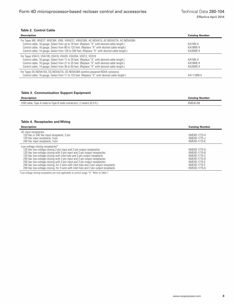
Table 4. Receptacles and Wiring
Description Catalog Number
AC input receptacles 120 Vac or 240 Vac input receptacle, 2-pin 120 Vac input receptacle, 3-pin 240 Vac input receptacle, 3-pin
KME4D-1775-HKME4D-1775-JKME4D-1775-K
Low-voltage closing receptacles* 120 Vac low-voltage closing 2-pin input and 2-pin output receptacles 120 Vac low-voltage closing with 3-pin input and 2-pin output receptacles 120 Vac low-voltage closing with inlet hole and 2-pin output receptacle 240 Vac low-voltage closing with 2-pin input and 2-pin output receptacles 240 Vac low-voltage closing with 3-pin input and 2-pin output receptacles 240 Vac low-voltage closing, for 2 wire with inlet hole and 2-pin output receptacle 240 Vac low-voltage closing, for 3 wire with inlet hole and 2-pin output receptacle
KME4D-1775-AKME4D-1775-BKME4D-1775-CKME4D-1775-DKME4D-1775-EKME4D-1775-FKME4D-1775-G
Table 3. Communication Support Equipment
Description Catalog Number
USB cable, Type A male-to-Type B male connectors, 2 meters (6.5-ft.) KME4D-66
Table 2. Control Cable
Description Catalog Number
For Types WE, WVE27, WVE38X, VWE, VWVE27, VWVE38X, AC-NOVA15, AC-NOVA27A, AC-NOVA38A Control cable, 18 gauge, Select from up to 79 feet. (Replace “X” with desired cable length.) Control cable, 16 gauge, Select from 80 to 125 feet. (Replace “X” with desired cable length.) Control cable, 14 gauge, Select from 126 to 200 feet. (Replace “X” with desired cable length.)
KA1ME-XKA18ME-XKA35ME-X
For Types VSA12, VSA12B, VSA16, VSA20, VSA20A, VSO12, VSO16 Control cable, 18 gauge, Select from 11 to 20 feet. (Replace “X” with desired cable length.) Control cable, 16 gauge, Select from 21 to 35 feet. (Replace “X” with desired cable length.) Control cable, 14 gauge, Select from 36 to 50 feet. (Replace “X” with desired cable length.)
KA1ME-XKA18ME-XKA35ME-X
For Types DC-NOVA15A, DC-NOVA27A, DC-NOVA38A (control-powered NOVA reclosers) Control cable, 16 gauge, Select from 11 to 125 feet. (Replace “X” with desired cable length.) KA1119R6-X
*Low-voltage closing receptacles are only applicable to control usage “A”. Refer to Table 1.
3
Technical Data 280-104Effective April 2014
Form 4D microprocessor-based recloser control and accessories
www.cooperpower.com
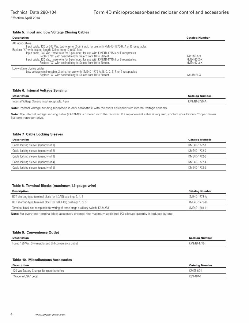
Table 5. Input and Low Voltage Closing Cables
Description Catalog Number
AC input cablesInput cable, 120 or 240 Vac, two-wire for 2-pin input, for use with KME4D-1775-H, A or D receptacles.
Replace “X” with desired length. Select from 10 to 80 feet.Input cable, 240 Vac, three-wire for 3-pin input, for use with KME4D-1775-K or E receptacles.
Replace “X” with desired length. Select from 10 to 80 feet.Input cable, 120 Vac, three-wire for 3-pin input, for use with KME4D-1775-J or B receptacles.
Replace “X” with desired length. Select from 10 to 80 feet.
KA11ME1-XKME4-67-2-XKME4-67-3-X
Low-voltage closing cablesLow-voltage closing cable, 2-wire, for use with KME4D-1775-A, B, C, D, E, F, or G receptacles.
Replace “X” with desired length. Select from 10 to 80 feet . KA13ME1-X
Table 7. Cable Locking Sleeves
Description Catalog Number
Cable locking sleeve, (quantity of 1) KME4D-1772-1
Cable locking sleeve, (quantity of 2) KME4D-1772-2
Cable locking sleeve, (quantity of 3) KME4D-1772-3
Cable locking sleeve, (quantity of 4) KME4D-1772-4
Cable locking sleeve, (quantity of 5) KME4D-1772-5
Table 9. Convenience Outlet
Description Catalog Number
Fused 120 Vac, 3-wire polarized GFI convenience outlet KME4D-1776
Table 10. Miscellaneous Accessories
Description Catalog Number
120 Vac Battery Charger for spare batteries KME5-60-1
“Made in USA” decal K89-407-1
Table 8. Terminal Blocks (maximum 12-gauge wire)
Description Catalog Number
BCT shorting-type terminal block for (LOAD) bushings 2, 4, 6 KME4D-1773-A
BCT shorting-type terminal block for (SOURCE) bushings 1, 3, 5 KME4D-1773-B
Terminal block and receptacle for wiring of three-stage auxiliary switch, KA542R3 . KME4D-1801-11
otee:N For every one terminal block accessory ordered, the maximum additional I/O allowed quantity is reduced by one.
Table 6. Internal Voltage Sensing
Description Catalog Number
Internal Voltage Sensing input receptacle, 4-pin KME4D-3799-A
otee:N Internal voltage sensing receptacle is only compatible with reclosers equipped with internal voltage sensors.
otee:N The internal voltage sensing cable (KA97ME) is ordered with the recloser. If a replacement cable is required, contact your Eaton’s Cooper Power Systems representative.
4
Technical Data 280-104Effective April 2014
Form 4D microprocessor-based recloser control and accessories
www.cooperpower.com
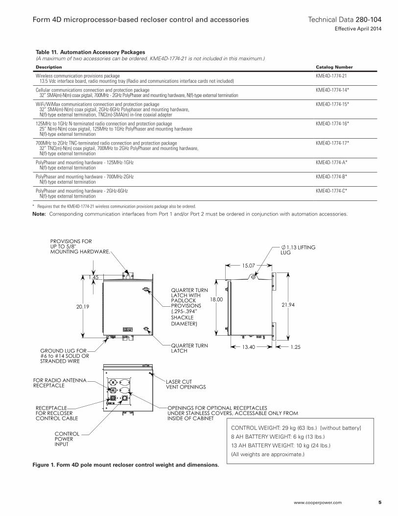
Figure 1. Form 4D pole mount recloser control weight and dimensions.
20.19
1.45
PROVISIONS FORUP TO 5/8"MOUNTING HARDWARE.
QUARTER TURNLATCH WITHPADLOCKPROVISIONS
QUARTER TURNLATCH GROUND LUG FOR
#6 to #14 SOLID ORSTRANDED WIRE
LASER CUT VENT OPENINGS
OPENINGS FOR OPTIONAL RECEPTACLESUNDER STAINLESS COVERS, ACCESSABLE ONLY FROMINSIDE OF CABINET
FOR RADIO ANTENNARECEPTACLE
CONTROL POWER INPUT
RECEPTACLEFOR RECLOSERCONTROL CABLE
21.9418.00
13.40 1.25
15.07
1.13 LIFTINGLUG
(.295-.394” SHACKLEDIAMETER)
CONTROL WEIGHT: 29 kg (63 lbs.) [without battery]
8 AH BATTERY WEIGHT: 6 kg (13 lbs.)
13 AH BATTERY WEIGHT: 10 kg (24 lbs.)
(All weights are approximate.)
* Requires that the KME4D-1774-21 wireless communication provisions package also be ordered.
Notee: Corresponding communication interfaces from Port 1 and/or Port 2 must be ordered in conjunction with automation accessories.
Table 11. Automation Accessory Packages(A maximum of two accessories can be ordered. KME4D-1774-21 is not included in this maximum.)
Description Catalog Number
Wireless communication provisions package 13.5 Vdc interface board, radio mounting tray (Radio and communications interface cards not included)
KME4D-1774-21
Cellular communications connection and protection package 32” SMA(m)-N(m) coax pigtail, 700MHz - 2GHz PolyPhaser and mounting hardware, N(f)-type external termination
KME4D-1774-14*
WiFi/WiMax communications connection and protection package 32” SMA(m)-N(m) coax pigtail, 2GHz-6GHz Polyphaser and mounting hardware, N(f)-type external termination, TNC(m)-SMA(m) in-line coaxial adapter
KME4D-1774-15*
125MHz to 1GHz N-terminated radio connection and protection package 25” N(m)-N(m) coax pigtail, 125MHz to 1GHz PolyPhaser and mounting hardware N(f)-type external termination
KME4D-1774-16*
700MHz to 2GHz TNC-terminated radio connection and protection package 32” TNC(m)-N(m) coax pigtail, 700MHz to 2GHz PolyPhaser and mounting hardware, N(f)-type external termination
KME4D-1774-17*
PolyPhaser and mounting hardware - 125MHz-1GHz N(f)-type external termination
KME4D-1774-A*
PolyPhaser and mounting hardware - 700MHz-2GHz N(f)-type external termination
KME4D-1774-B*
PolyPhaser and mounting hardware - 2GHz-6GHz N(f)-type external termination
KME4D-1774-C*
5
Technical Data 280-104Effective April 2014
Form 4D microprocessor-based recloser control and accessories
www.cooperpower.com
Control featuresControl security
The Form 4D recloser control has multiple customer-programmable security codes to limit control programming and viewing function access to authorized personnel. The Form 4D control is capable of supporting strong passwords containing letters (upper and lower case), numbers, and symbols. The front panel Human-Machine Interface (HMI) includes a user-selected security code to access the settings. Plus, the ProView NXG interface software has its own security levels for multiple-user access.
Protection profiles
The Form 4D control provides two protection profiles, each capable of fully specifying the operation of the control. The protection profiles are selectable through the front-panel push-button interface or through the interface software and USB communication ports. Each protection profile contains overcurrent protection, voltage protection, frequency protection, sync check, sensitive earth fault protection, and operation settings.
Reclosing and overcurrent protection/TCCs
The Form 4D control offers flexible phase and ground overcurrent protection which can be programmed with up to four operations-to-lockout. Each time-current curve (TCC) can be individually programmed from up to fifty standard curves which can be further customized. Time-current curves are available for fast and delayed operations. The time-current curves are also selectable from a graphical TCC editor to visualize any modifications prior to configuring the control. Reclose intervals and reset time can also be programmed by the user.
TCC editor II
Coordination and actual time current modifications are available with a graphic, interactive TCC editor. The TCC Editor II includes a complete database of standard recloser industry time current curves, both ANSI® and IEC types, along with the ability to customize the TCCs with multipliers, constant time adders, or minimum response time adders. The user is also able to derive their own specific TCC through data point entry.
Sensitive earth fault
The Form 4D control includes Sensitive Earth Fault (SEF) protection, which will provide tripping of the recloser for ground currents below normal ground minimum trip elements. The SEF feature has programmable operations-to-lockout and reclose intervals independent of the ground settings and is independently selectable for each protection profile.
High current lockout
The High Current Lockout (HCL) feature will automatically lockout the control when the current exceeds a programmed threshold. The active number of operations-to-lockout is selectable for both phase and ground and is independently selectable for each protection profile.
Cold load pickup
The Form 4D control provides a Cold Load Pickup (CLPU) feature that will prevent the control from tripping due to short-term increases in current caused by loss of normal load diversity or feeder inrush. This feature has an independently programmable minimum trip value, time-current curve, reclose interval, and number of operations to lockout for each protection profile as well as for both phase and ground. The CLPU feature will also inhibit ‘normal’ overcurrent protection during the CLPU active time.
Hot line tag
The Form 4D includes a Hot Line Tag (HLT) switch that will block all Close operations, local or remote, for live-line work. The control will trip on one operation-to-lockout on the composite curve of the HLT definite time and the TCC1 curve, whichever is faster, when HLT is active. Hot Line Tag takes precedence over Cold Load Pickup, Non-Reclosing, and Fast Trips Disabled. The Hot Line Tag time delay is independently selectable for each protection profile.
Fast trips disabled
The Fast Trips Disabled feature will ignore the normal TCCs and number of trips and instead use the Fast Trips Disabled settings when Fast Trips Disabled is active. Fast Trips Disabled will have separate phase and ground settings and is independently selectable for each protection profile.
Ground trip precedence
The Form 4D control comes equipped with an option for Ground Trip Precedence. When ground trip precedence is selected to be active, the sequence uses the ground operations to lockout for fault current above both phase and ground minimum trip values.
Voltage protection
The Form 4D control includes three levels each of over- and undervoltage protection and includes single-phase and three-phase protection for both over- and undervoltage conditions. Both functions include a phase pickup, a phase time delay, a three-phase pickup, and three-phase time delay. One overvoltage and one undervoltage alarm is also provided.
Frequency protection
Six levels of frequency protection are included with the control, with each level configurable as either overfrequency or underfrequency. A frequency restoration function, which can be enabled or disabled, will allow the recloser to automatically close should the frequency return to within configured settings for a user-settable time.
Sync check
The Form 4D control includes sync check functionality, which is used to qualify any close signal to the recloser when enabled via the sync check settings. Sync check allows for closing for any combination of dead/live bus/line, and to perform anticipatory closing for a live bus/live line condition by calculating slip and anticipating the mechanism closing delay. In addition to the anticipatory close calculation, the sync check system performs verification of line and bus voltage magnitudes and frequencies to determine that they are within pre-determined ranges, and that the angular differences between the two systems is also within the pre-determined range.
Sequence coordination
The Form 4D control Sequence Coordination feature will allow the control to step through selected operations in the operating sequence without tripping when a down-line recloser is proceeding through its reclose sequence. The number of advances is programmable from one to three operations to provide trip coordination with the down-line recloser.
6
Technical Data 280-104Effective April 2014
Form 4D microprocessor-based recloser control and accessories
www.cooperpower.com
Manual close time delay
The Form 4D control includes a Manual Close Delay which provides a delay from the time the manual CLOSE button is pushed to the time the manual close operation is performed.
Metering
The Form 4D control comes equipped with a full complement of metering capabilities, which include instantaneous, demand, demand peak, and energy metering. The control will be capable of the following metering values:
• Real and reactive power for single- and three-phase, includingdirection of power flow.
• Demand currents on a per-phase basis.• Instantaneous currents, including ground current.• Instantaneous voltage on a per-phase basis.• Instantaneous frequency.• Energy on a per-phase basis.• Positive, negative, and zero sequence voltages.• Harmonics on a per-phase basis for voltage and current.• Instantaneous power factor on a per-phase basis.• Metering settings which include demand interval, and alarm
thresholds for current, single-phase kW, three-phase kW, single-phase kVAR, and three-phase kVAR.
Diagnostic tools
The Form 4D control comes complete with a suite of diagnostic tools to help troubleshoot problems, analyze system events and conditions, and monitor the life of your recloser. All diagnostic information is stored in non-volatile memory so even if the control loses power, all system and event information will remain intact.
Recloser wear monitor
The Recloser Wear Monitor will observe the life of the recloser apparatus by recording how many times the recloser has been opened as well as keep track of the current interrupted in percentage compared to preset total Duty Cycle Factor. The monitor allows for programmable entries to preset the duty of an existing recloser.
Sequence of events recorder
The Sequence of Events (SOE) Recorder is capable of capturing discrete events such as Open/Close status changes, faults, mechanism failures, etc. The SOE places an accurate time stamp and analog information on the events and stores them in non-volatile memory so they won’t be lost in the event that the control loses power. The SOE recorder is capable of maintaining up to 1000 events and can record up to 116 different event types, including overcurrent trip, control trip, non-reclose ON/OFF, external alarm, and control lockout.
Data profiler
A fully configurable data profiler is available which allows the user to collect information by sampling data at selectable intervals. These time-stamped values can then be viewed to determine weekly load profiles, daily harmonic disturbances, or hourly voltage fluctuations. The number of days of information the data profiler can provide depends upon configuration parameters.
Internal voltage sensingA four-wire cable and input receptacle accessory is required for Type NOVATM three-phase reclosers with the internal voltage sensing (IVS) option. Internal voltage sensors, located on the source side, indicate voltage magnitude within an accuracy 2% or better and a phase degree accuracy within 1.5 degrees (includes sensor, cable, and control). The 4-pin receptacle accessory is prewired to the voltage inputs on the control.
Contact input/output (I/O) module option
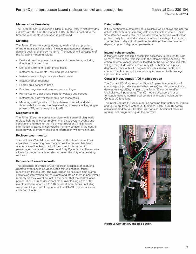
The Contact I/O Module option (Figure 2) permits connection of contact-type input devices (switches, relays) and discrete indicating devices (relays, LEDs, lamps) to the Form 4D control to effect local discrete input/output. The I/O module accessory is used for supplementing normal local controls and status indicators for Contact I/O functions.
The initial Contact I/O Module option contains four factory-set inputs and four outputs for Contact I/O functions. Each Form 4D control can accommodate four Contact I/O modules. Additional modules require user programming via the software.
Figure 2. Contact I/O module option.
7
Technical Data 280-104Effective April 2014
Form 4D microprocessor-based recloser control and accessories
www.cooperpower.com
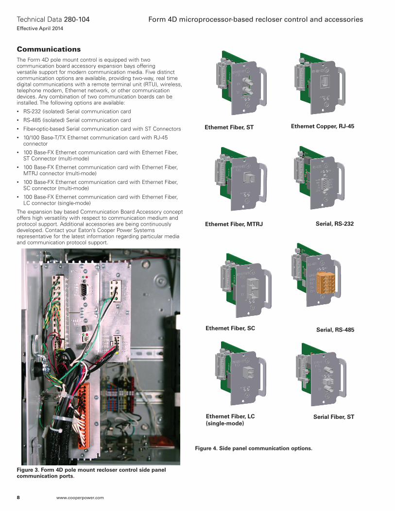
CommunicationsThe Form 4D pole mount control is equipped with two communication board accessory expansion bays offering versatile support for modern communication media. Five distinct communication options are available, providing two-way, real time digital communications with a remote terminal unit (RTU), wireless, telephone modem, Ethernet network, or other communication devices. Any combination of two communication boards can be installed. The following options are available:• RS-232 (isolated) Serial communication card• RS-485 (isolated) Serial communication card• Fiber-optic-based Serial communication card with ST Connectors• 10/100 Base-T/TX Ethernet communication card with RJ-45
connector• 100 Base-FX Ethernet communication card with Ethernet Fiber,
ST Connector (multi-mode)• 100 Base-FX Ethernet communication card with Ethernet Fiber,
MTRJ connector (multi-mode)• 100 Base-FX Ethernet communication card with Ethernet Fiber,
SC connector (multi-mode)• 100 Base-FX Ethernet communication card with Ethernet Fiber,
LC connector (single-mode)
The expansion bay based Communication Board Accessory concept offers high versatility with respect to communication medium and protocol support. Additional accessories are being continuously developed. Contact your Eaton’s Cooper Power Systems representative for the latest information regarding particular media and communication protocol support.
Figure 3. Form 4D pole mount recloser control side panel communication ports.
Figure 4. Side panel communication options.
Ethernet Copper, RJ-45Ethernet Fiber, ST
Ethernet Fiber, MTRJ Serial, RS-232
Ethernet Fiber, LC (single-mode)
Serial, RS-485Ethernet Fiber, SC
Serial Fiber, ST
8
Technical Data 280-104Effective April 2014
Form 4D microprocessor-based recloser control and accessories
www.cooperpower.com
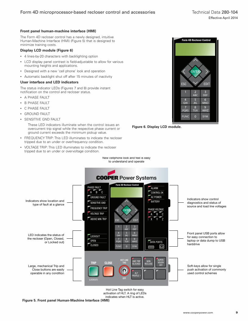
Front panel human-machine interface (HMI)
The Form 4D recloser control has a newly designed, intuitive Human-Machine Interface (HMI) (Figure 5) that is designed to minimize training costs.
Display LCD module (Figure 6)
• 4 lines-by-20 characters with backlighting option• LCD display panel contrast is field-adjustable to allow for various
mounting heights and applications.• Designed with a new ‘cell phone’ look and operation• Automatic backlight shut off after 15 minutes of inactivity
User interface and LED indicators
The status indicator LEDs (Figures 7 and 8) provide instant notification on the control and recloser status.• A PHASE FAULT• B PHASE FAULT• C PHASE FAULT• GROUND FAULT• SENSITIVE GND FAULT
These LED indicators illuminate when the control issues an overcurrent trip signal while the respective phase current or ground current exceeds the minimum pickup value.
• FREQUENCY TRIP: This LED illuminates to indicate the recloser tripped due to an under or overfrequency condition.
• VOLTAGE TRIP: This LED illuminates to indicate the recloser tripped due to an under or overvoltage condition.
New cellphone look and feel is easyto understand and operate
Indicators show location andtype of fault at a glance
LED indicates the status ofthe recloser (Open, Closed,
or Locked out)
Large, mechanical Trip andClose buttons are easily
operable in any condition
Indicators show controldiagnostics and status ofsource and load line voltages
Front panel USB ports allowfor easy connection tolaptop or data dump to USBharddrive
Soft-keys allow for singlepush activation of commonlyused control schemes
Hot Line Tag switch for easyactivation of HLT. A ring of LEDs
indicates when HLT is active.
DATA PORTS
ENTER
EDITESC
PHASE FAULT
A B C
GROUND FAULT
ABOVE MIN TRIP
LOCKOUT
OPEN
CLOSED
VOLTAGE TRIP
FREQUENCY TRIP
SENSITIVE GND
A B C
X Y Z
PHASE VOLTAGE
ALARM
BATTERY
AC POWER
CONTROL OK
ALTPROFILE 1
GND TRIPBLOCKED
NONRECLOSE
SUPER-VISORY
OFF
HOT LINETAGTRIP
OFF(LOCKOUT)
CLOSE
Figure 5. Front panel Human-Machine Interface (HMI)
DATA PORTS
ENTER
EDITESC
PHASE FAULT
A B C
GROUND FAULT
ABOVE MIN TRIP
LOCKOUT
OPEN
CLOSED
VOLTAGE TRIP
FREQUENCY TRIP
SENSITIVE GND
A B C
X Y Z
PHASE VOLTAGE
ALARM
BATTERY
AC POWER
CONTROL OK
ALTPROFILE 1
GND TRIPBLOCKED
NONRECLOSE
SUPER-VISORY
OFF
HOT LINETAGTRIP
OFF(LOCKOUT)
CLOSE
Figure 6. Display LCD module.
9
Technical Data 280-104Effective April 2014
Form 4D microprocessor-based recloser control and accessories
www.cooperpower.com
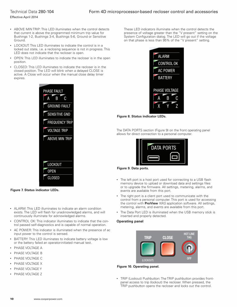
• ABOVE MIN TRIP: This LED illuminates when the control detectsthat current is above the programmed minimum trip value forBushings 1-2, Bushings 3-4, Bushings 5-6, Ground or Sensitive Ground.
• LOCKOUT: This LED illuminates to indicate the control is in alocked out state, i.e. a reclosing sequence is not in progress. This LED does not indicate that the recloser is open.
• OPEN: This LED illuminates to indicate the recloser is in the openposition.
• CLOSED: This LED illuminates to indicate the recloser is in theclosed position. The LED will blink when a delayed CLOSE isactive. A Close will occur when the manual close delay timer expires.
• ALARM: This LED illuminates to indicate an alarm conditionexists. The LED will flash for unacknowledged alarms, and will continuously illuminate for acknowledged alarms.
• CONTROL OK: This indicator illuminates to indicate that the con-trol passed self-diagnostics and is capable of normal operation.
• AC POWER: This indicator is illuminated when the presence of acinput power to the control is sensed.
• BATTERY: This LED illuminates to indicate battery voltage is lowor the battery failed an operator-initiated manual test.
• PHASE VOLTAGE A• PHASE VOLTAGE B• PHASE VOLTAGE C• PHASE VOLTAGE X• PHASE VOLTAGE Y• PHASE VOLTAGE Z
These LED indicators illuminate when the control detects the presence of voltage greater than the “V present” setting on the System Configuration dialog. The LED will go out if the voltage on that phase is less than 95% of the “V present” setting.
The DATA PORTS section (Figure 9) on the front operating panel allows for direct connection to a personal computer.
• The left port is a host port used for connecting to a USB flash memory device to upload or download data and settings files or to upgrade the firmware. All settings, metering, alarms, and events are available from this port.
• The right port is a client port used to communicate with the control from a personal computer. This port is used for accessing the control with ProView NXG application software. All settings, metering, alarms, and events are available from this port.
• The Data Port LED is illuminated when the USB memory stick is inserted and properly detected.
Operating panel
• TRIP (Lockout) Pushbutton: The TRIP pushbutton provides front-panel access to trip (lockout) the recloser. When pressed, theTRIP pushbutton opens the recloser and locks out the control.
DATA PORTS
ENTER
EDITESC
PHASE FAULT
A B C
GROUND FAULT
ABOVE MIN TRIP
LOCKOUT
OPEN
CLOSED
VOLTAGE TRIP
FREQUENCY TRIP
SENSITIVE GND
A B C
X Y Z
PHASE VOLTAGE
ALARM
BATTERY
AC POWER
CONTROL OK
ALTPROFILE 1
GND TRIPBLOCKED
NONRECLOSE
SUPER-VISORY
OFF
HOT LINETAGTRIP
OFF(LOCKOUT)
CLOSE
Figure 7. Status indicator LEDs.
DATA PORTS
ENTER
EDITESC
PHASE FAULT
A B C
GROUND FAULT
ABOVE MIN TRIP
LOCKOUT
OPEN
CLOSED
VOLTAGE TRIP
FREQUENCY TRIP
SENSITIVE GND
A B C
X Y Z
PHASE VOLTAGE
ALARM
BATTERY
AC POWER
CONTROL OK
ALTPROFILE 1
GND TRIPBLOCKED
NONRECLOSE
SUPER-VISORY
OFF
HOT LINETAGTRIP
OFF(LOCKOUT)
CLOSE
Figure 8. Status indicator LEDs.
DATA PORTS
ENTER
EDITESC
PHASE FAULT
A B C
GROUND FAULT
ABOVE MIN TRIP
LOCKOUT
OPEN
CLOSED
VOLTAGE TRIP
FREQUENCY TRIP
SENSITIVE GND
A B C
X Y Z
PHASE VOLTAGE
ALARM
BATTERY
AC POWER
CONTROL OK
ALTPROFILE 1
GND TRIPBLOCKED
NONRECLOSE
SUPER-VISORY
OFF
HOT LINETAGTRIP
OFF(LOCKOUT)
CLOSE
Figure 9. Data ports.
DATA PORTS
ENTER
EDITESC
PHASE FAULT
A B C
GROUND FAULT
ABOVE MIN TRIP
LOCKOUT
OPEN
CLOSED
VOLTAGE TRIP
FREQUENCY TRIP
SENSITIVE GND
A B C
X Y Z
PHASE VOLTAGE
ALARM
BATTERY
AC POWER
CONTROL OK
ALTPROFILE 1
GND TRIPBLOCKED
NONRECLOSE
SUPER-VISORY
OFF
HOT LINETAGTRIP
OFF(LOCKOUT)
CLOSE
Figure 10. Operating panel.
10
Technical Data 280-104Effective April 2014
Form 4D microprocessor-based recloser control and accessories
www.cooperpower.com
• CLOSE Pushbutton: When pressed, the CLOSE pushbuttonreturns the control to the initial or home sequence position, clos-ing the recloser. The control is ready for the start of a new trip/close sequence.
• HOT LINE TAG ON/OFF: Hot Line Tag is provided for live-line workapplications. All closing operations are disabled when the Hot LineTag feature is activated.
Hot Line Tag prevents all closing attempts from the control and shifts protection to one trip-to-lockout on the composite curve of the Hot Line Tag definite time and the TCC1 curve (whichever is faster). Hot Line Tag takes precedence over Cold Load Pickup, Non-Reclosing, and Fast Trips Disabled.
Hot Line Tag is activated from either the operator panel toggle switch, local or remote communications, or configurable logic. All sources must be off to de-activate Hot Line Tag.
The Hot Line Tag function may only be reset by the source which initiates it.
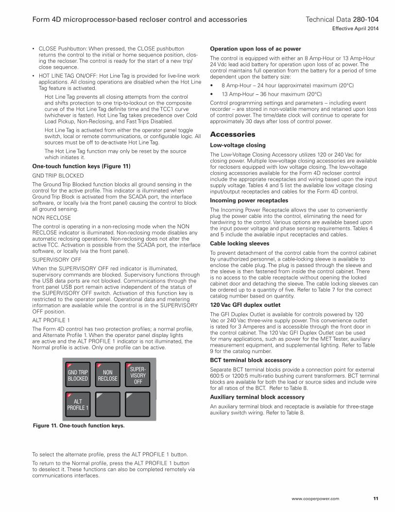
One-touch function keys (Figure 11)
GND TRIP BLOCKED
The Ground Trip Blocked function blocks all ground sensing in the control for the active profile. This indicator is illuminated when Ground Trip Block is activated from the SCADA port, the interface software, or locally (via the front panel) causing the control to block all ground sensing.
NON RECLOSE
The control is operating in a non-reclosing mode when the NON RECLOSE indicator is illuminated. Non-reclosing mode disables any automatic reclosing operations. Non-reclosing does not alter the active TCC. Activation is possible from the SCADA port, the interface software, or locally (via the front panel).
SUPERVISORY OFF
When the SUPERVISORY OFF red indicator is illuminated,supervisory commands are blocked. Supervisory functions through the USB data ports are not blocked. Communications through the front panel USB port remain active independent of the status of the SUPERVISORY OFF switch. Activation of this function key is restricted to the operator panel. Operational data and metering information are available while the control is in the SUPERVISORY OFF position.
ALT PROFILE 1
The Form 4D control has two protection profiles; a normal profile, and Alternate Profile 1. When the operator panel display lightsare active and the ALT PROFILE 1 indicator is not illuminated, the Normal profile is active. Only one profile can be active.
To select the alternate profile, press the ALT PROFILE 1 button.
To return to the Normal profile, press the ALT PROFILE 1 button to deselect it. These functions can also be completed remotely via communications interfaces.
Operation upon loss of ac power
The control is equipped with either an 8 Amp-Hour or 13 Amp-Hour 24 Vdc lead acid battery for operation upon loss of ac power. The control maintains full operation from the battery for a period of time dependent upon the battery size:
• 8 Amp-Hour – 24 hour (approximate) maximum (20°C)
• 13 Amp-Hour – 36 hour maximum (20°C)
Control programming settings and parameters – including event recorder – are stored in non-volatile memory and retained upon loss of control power. The time/date clock will continue to operate for approximately 30 days after loss of control power.
AccessoriesLow-voltage closing
The Low-Voltage Closing Accessory utilizes 120 or 240 Vac for closing power. Multiple low-voltage closing accessories are available for reclosers equipped with low voltage closing. The low-voltage closing accessories available for the Form 4D recloser control include the appropriate receptacles and wiring based upon the input supply voltage. Tables 4 and 5 list the available low voltage closing input/output receptacles and cables for the Form 4D control.
Incoming power receptacles
The Incoming Power Receptacle allows the user to conveniently plug the power cable into the control, eliminating the need for hardwiring to the control. Various options are available based upon the input power voltage and phase sensing requirements. Tables 4 and 5 include the available input receptacles and cables.
Cable locking sleeves
To prevent detachment of the control cable from the control cabinet by unauthorized personnel, a cable-locking sleeve is available to enclose the cable plug. The plug is passed through the sleeve and the sleeve is then fastened from inside the control cabinet. There is no access to the cable receptacle without opening the locked cabinet door and detaching the sleeve. The cable locking sleeves can be ordered up to a quantity of five. Refer to Table 7 for the correct catalog number based on quantity.
120 Vac GFI duplex outlet
The GFI Duplex Outlet is available for controls powered by 120 Vac or 240 Vac three-wire supply power. This convenience outlet is rated for 3 Amperes and is accessible through the front door in the control cabinet. The 120 Vac GFI Duplex Outlet can be used for many applications, such as power for the MET Tester, auxiliary measurement equipment, and supplemental lighting. Refer to Table 9 for the catalog number.
BCT terminal block accessory
Separate BCT terminal blocks provide a connection point for external 600:5 or 1200:5 multi-ratio bushing current transformers. BCT terminal blocks are available for both the load or source sides and include wire for all ratios of the BCT. Refer to Table 8.
Auxiliary terminal block accessory
An auxiliary terminal block and receptacle is available for three-stage auxiliary switch wiring. Refer to Table 8.
DATA PORTS
ENTER
EDITESC
PHASE FAULT
A B C
GROUND FAULT
ABOVE MIN TRIP
LOCKOUT
OPEN
CLOSED
VOLTAGE TRIP
FREQUENCY TRIP
SENSITIVE GND
A B C
X Y Z
PHASE VOLTAGE
ALARM
BATTERY
AC POWER
CONTROL OK
ALTPROFILE 1
GND TRIPBLOCKED
NONRECLOSE
SUPER-VISORY
OFF
HOT LINETAGTRIP
OFF(LOCKOUT)
CLOSE
Figure 11. One-touch function keys.
11
Technical Data 280-104Effective April 2014
Form 4D microprocessor-based recloser control and accessories
www.cooperpower.com
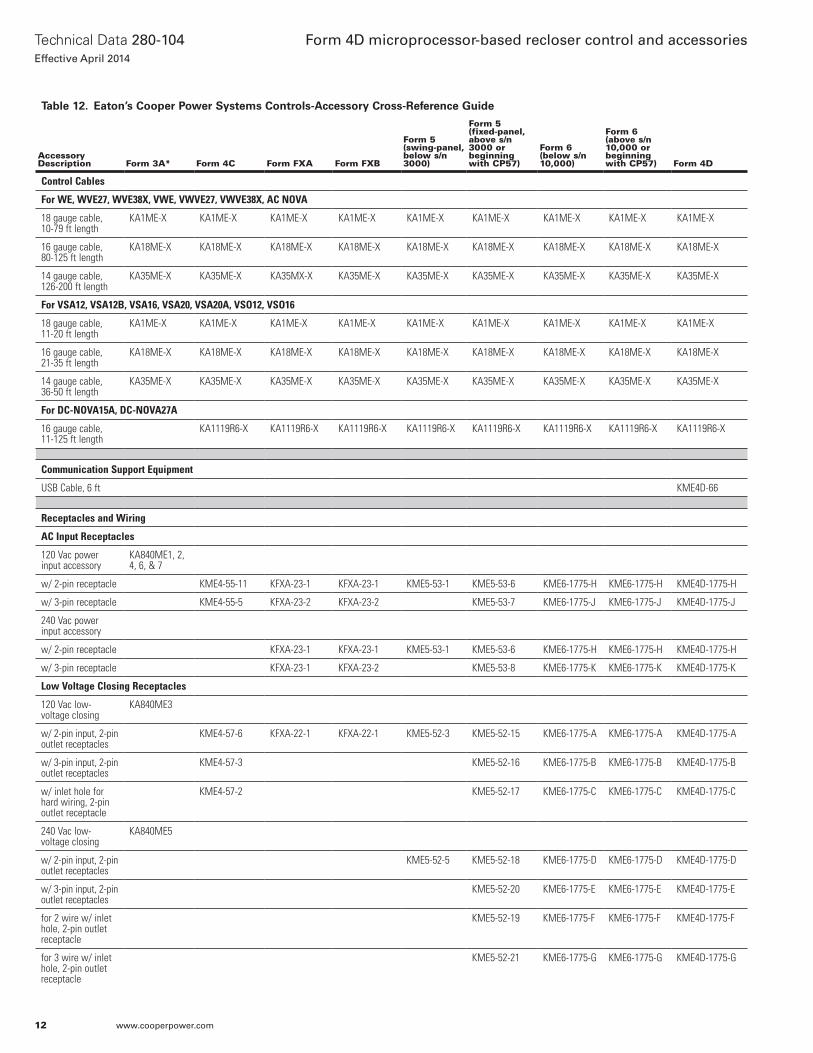
Table 12. Eaton’s Cooper Power Systems Controls-Accessory Cross-Reference Guide
Accessory Description Form 3A* Form 4C Form FXA Form FXB
Form 5 (swing-panel, below s/n 3000)
Form 5 (fixed-panel, above s/n 3000 or beginning with CP57)
Form 6 (below s/n 10,000)
Form 6 (above s/n 10,000 or beginning with CP57) Form 4D
Control Cables
For WE, WVE27, WVE38X, VWE, VWVE27, VWVE38X, AC NOVA
18 gauge cable, 10-79 ft length
KA1ME-X KA1ME-X KA1ME-X KA1ME-X KA1ME-X KA1ME-X KA1ME-X KA1ME-X KA1ME-X
16 gauge cable, 80-125 ft length
KA18ME-X KA18ME-X KA18ME-X KA18ME-X KA18ME-X KA18ME-X KA18ME-X KA18ME-X KA18ME-X
14 gauge cable, 126-200 ft length
KA35ME-X KA35ME-X KA35MX-X KA35ME-X KA35ME-X KA35ME-X KA35ME-X KA35ME-X KA35ME-X
For VSA12, VSA12B, VSA16, VSA20, VSA20A, VSO12, VSO16
18 gauge cable, 11-20 ft length
KA1ME-X KA1ME-X KA1ME-X KA1ME-X KA1ME-X KA1ME-X KA1ME-X KA1ME-X KA1ME-X
16 gauge cable, 21-35 ft length
KA18ME-X KA18ME-X KA18ME-X KA18ME-X KA18ME-X KA18ME-X KA18ME-X KA18ME-X KA18ME-X
14 gauge cable, 36-50 ft length
KA35ME-X KA35ME-X KA35ME-X KA35ME-X KA35ME-X KA35ME-X KA35ME-X KA35ME-X KA35ME-X
For DC-NOVA15A, DC-NOVA27A
16 gauge cable, 11-125 ft length
KA1119R6-X KA1119R6-X KA1119R6-X KA1119R6-X KA1119R6-X KA1119R6-X KA1119R6-X KA1119R6-X
Communication Support Equipment
USB Cable, 6 ft KME4D-66
Receptacles and Wiring
AC Input Receptacles
120 Vac power input accessory
KA840ME1, 2, 4, 6, & 7
w/ 2-pin receptacle KME4-55-11 KFXA-23-1 KFXA-23-1 KME5-53-1 KME5-53-6 KME6-1775-H KME6-1775-H KME4D-1775-H
w/ 3-pin receptacle KME4-55-5 KFXA-23-2 KFXA-23-2 KME5-53-7 KME6-1775-J KME6-1775-J KME4D-1775-J
240 Vac power input accessory
w/ 2-pin receptacle KFXA-23-1 KFXA-23-1 KME5-53-1 KME5-53-6 KME6-1775-H KME6-1775-H KME4D-1775-H
w/ 3-pin receptacle KFXA-23-1 KFXA-23-2 KME5-53-8 KME6-1775-K KME6-1775-K KME4D-1775-K
Low Voltage Closing Receptacles
120 Vac low-voltage closing
KA840ME3
w/ 2-pin input, 2-pin outlet receptacles
KME4-57-6 KFXA-22-1 KFXA-22-1 KME5-52-3 KME5-52-15 KME6-1775-A KME6-1775-A KME4D-1775-A
w/ 3-pin input, 2-pin outlet receptacles
KME4-57-3 KME5-52-16 KME6-1775-B KME6-1775-B KME4D-1775-B
w/ inlet hole for hard wiring, 2-pin outlet receptacle
KME4-57-2 KME5-52-17 KME6-1775-C KME6-1775-C KME4D-1775-C
240 Vac low-voltage closing
KA840ME5
w/ 2-pin input, 2-pin outlet receptacles
KME5-52-5 KME5-52-18 KME6-1775-D KME6-1775-D KME4D-1775-D
w/ 3-pin input, 2-pin outlet receptacles
KME5-52-20 KME6-1775-E KME6-1775-E KME4D-1775-E
for 2 wire w/ inlet hole, 2-pin outlet receptacle
KME5-52-19 KME6-1775-F KME6-1775-F KME4D-1775-F
for 3 wire w/ inlet hole, 2-pin outlet receptacle
KME5-52-21 KME6-1775-G KME6-1775-G KME4D-1775-G
12
Technical Data 280-104Effective April 2014
Form 4D microprocessor-based recloser control and accessories
www.cooperpower.com
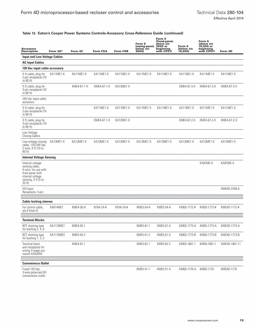
Table 12. Eaton’s Cooper Power Systems Controls-Accessory Cross-Reference Guide (continued)
Accessory Description Form 3A* Form 4C Form FXA Form FXB
Form 5 (swing-panel, below s/n 3000)
Form 5 (fixed-panel, above s/n 3000 or beginning with CP57)
Form 6 (below s/n 10,000)
Form 6 (above s/n 10,000 or beginning with CP57) Form 4D
Input and Low Voltage Cables
AC Input Cables
120 Vac input cable accessory
X ft cable, plug for 2-pin receptacle (10 to 80 ft)
KA11ME1-X KA11ME1-X KA11ME1-X KA11ME1-X KA11ME1-X KA11ME1-X KA11ME1-X KA11ME1-X KA11ME1-X
X ft cable, plug for 3-pin receptacle (10 to 80 ft)
KME4-67-1-X KME4-67-1-X KA13ME1-X KME4-67-3-X KME4-67-3-X KME4-67-3-X
240 Vac input cable accessory
X ft cable, plug for 2-pin receptacle (10 to 80 ft)
KA11ME1-X KA11ME1-X KA11ME1-X KA11ME1-X KA11ME1-X KA11ME1-X KA11ME1-X
X ft cable, plug for 3-pin receptacle (10 to 80 ft)
KME4-67-1-X KA13ME1-X KME4-67-2-X KME4-67-2-X KME4-67-2-X
Low Voltage Closing Cables
Low-voltage closing cable, 120/240 Vac, 2 wire, X ft (10 to 80 ft)
KA13ME1-X KA13ME1-X KA13ME1-X KA13ME1-X KA13ME1-X KA13ME1-X KA13ME1-X KA13ME1-X KA13ME1-X
Internal Voltage Sensing
Internal voltage sensing cable, 4-wire, for use with front panel with internal voltage sensing, X ft (5 to 35 ft)
KA97ME-X KA97ME-X
IVS Input Receptacle, 4-pin
KME4D-3799-A
Cable-locking sleeves
For control cable, qty # (max 5)
KA614ME1 KME4-56-A KFXA-24-# KFXA-24-# KME5-54-A KME5-54-A KME6-1772-# KME6-1772-# KME4D-1772-#
Terminal Blocks
BCT shorting-type for bushing 2, 4, 6
KA1170ME1 KME4-83-1 KME5-61-1 KME5-61-4 KME6-1773-A KME6-1773-A KME4D-1773-A
BCT shorting-type for bushing 1, 3, 5
KA1170ME2 KME4-83-2 KME5-61-2 KME5-61-5 KME6-1773-B KME6-1773-B KME4D-1773-B
Terminal block and receptacle for wiring 3-stage aux switch KA542R3
KME4-81-1 KME5-62-1 KME5-62-2 KME6-1801-1 KME6-1801-1 KME4D-1801-11
Convenience Outlet
Fused 120 Vac, 3-wire polarized GFI convenience outlet
KME5-51-1 KME5-51-4 KME6-1776-A KME6-1776 KME4D-1776
13
Technical Data 280-104Effective April 2014
Form 4D microprocessor-based recloser control and accessories
www.cooperpower.com
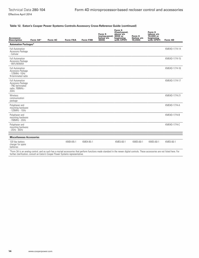
Table 12. Eaton’s Cooper Power Systems Controls-Accessory Cross-Reference Guide (continued)
Accessory Description Form 3A* Form 4C Form FXA Form FXB
Form 5 (swing-panel, below s/n 3000)
Form 5 (fixed-panel, above s/n 3000 or beginning with CP57)
Form 6 (below s/n 10,000)
Form 6 (above s/n 10,000 or beginning with CP57) Form 4D
Automation Packages*
Full Automation Accessory Package - Cellular
KME4D-1774-14
Full Automation Accessory Package - WiFi/WiMAX
KME4D-1774-15
Full Automation Accessory Package - 125MHz -1GHz N-terminated radio
KME4D-1774-16
Full Automation Accessory Package - TNC-terminated radio, 700MHz - 2GHz
KME4D-1774-17
Wireless communication package
KME4D-1774-21
Polyphaser and mounting hardware - 125MHz - 1GHz
KME4D-1774-A
Polyphaser and mounting hardware - 700MHz - 2GHz
KME4D-1774-B
Polyphaser and mounting hardware - 2GHz - 6GHz
KME4D-1774-C
Miscellaneous Accessories
120 Vac battery charger for spare batteries
KME4-85-1 KME4-85-1 KME5-60-1 KME5-60-1 KME5-60-1 KME5-60-1
*Form 3A is an analog control, and as such has a myriad accessories that perform functions made standard in the newer digital controls. These accessories are not listed here. For further clarification, consult an Eaton’s Cooper Power Systems representative.
14
Technical Data 280-104Effective April 2014
Form 4D microprocessor-based recloser control and accessories
www.cooperpower.com

15
Technical Data 280-104Effective April 2014
Form 4D microprocessor-based recloser control and accessories
www.cooperpower.com
Eaton, Cooper Power Systems, NOVA, and ProView NXG are valuable trademarks of Eaton in the U.S. and other countries. You are not permitted to use the these trademarks without the prior written consent of Eaton.IEEE Std C57.12.28™-2005 and Std C57.12.29™-2005 standards are trademarks of the Institute of Electrical and Electronics Engineers, Inc., (IEEE). This publication is not endorsed or approved by the IEEE.IEEE® is a registered trademark of the Institute of Electrical and Electronics Engineers, Inc.ANSI® is a registered trademark of American National Standards Institute.
Form 4D microprocessor-based recloser control and accessories
Eaton1000 Eaton BoulevardCleveland, OH 44122United StatesEaton.com
Eaton’s Cooper Power Systems Business2300 Badger DriveWaukesha, WI 53188United StatesCooperpower.com
© 2014 EatonAll Rights ReservedPrinted in USAPublication No. 280-104April 2014
Technical Data 280-104Effective April 2014
For Eaton’s Cooper Power Systems Form 4D recloser product information call 1-877-277-4636 or visit: www.cooperpower.com.
borderstates.com