Embed Size (px)
Citation preview

292 IEEE TRANSACTIONS ON MICROWAVE THEORY AND TECHNIQUES, VOL. 52, NO. 1, JANUARY 2004
Fast CAD and Optimization of WaveguideComponents and Aperture Antennas
by Hybrid MM/FE/MoM/FDMethods—State-of-the-Art
and Recent AdvancesFritz Arndt, Fellow, IEEE, J. Brandt, Member, IEEE, V. Catina, Member, IEEE, J. Ritter, Member, IEEE, I. Rullhusen,
J. Dauelsberg, U. Hilgefort, and W. Wessel
Invited Paper
Abstract—This paper presents an overview of thestate-of-the-art of hybrid mode-matching (MM)/finite-element(FE)/method-of-moments (MoM)/finite-difference (FD)techniques applied for the rigorous, fast computer-aided designand optimization of waveguide components, combline filters, andcoupled horns, as well as of slot arrays, and describes some recentadvances. Related aspects involve the inclusion of coaxial anddielectric structures for related filters, the extension to multiportsat cross-coupled filters, the rigorous consideration of outer andinner mutual coupling effects at coupled horn and slot arrays, theapplication of the multilevel fast multipole algorithm for the moreefficient MoM calculation part of horns and horn clusters, andthe utilization of the MoM for the design of arbitrarily shapedthree-dimensional waveguide elements. The described hybridtechniques combine advantageously the efficiency of the MMmethod with the flexibility of FE, MoM, and FD methods. Typicalapplication examples demonstrate the versatility of the hybridtechniques; their accuracy is verified by available measurements.
Index Terms—Computer-aided design (CAD), finite-difference(FD) method, finite-element (FE) method, horn antennas, hybridmethods, method-of-moments (MoM), mode-matching (MM)method, optimization, waveguide components, waveguide filters.
I. INTRODUCTION
TO MEET THE increasing demand for enhanced mi-crowave components and antennas in wireless terrestrial
and satellite-based communications, and for radar applications,accurate and efficient computer-aided design (CAD) toolsare required. Due to efforts during the 1990s—the decade of
Manuscript received January 29, 2003; revised July 18, 2003.F. Arndt, V. Catina, and I. Rullhusen are with the Microwave Department,
University of Bremen, D-28359 Bremen, Germany.J. Brandt, J. Dauelsberg, U. Hilgefort, and W. Wessel are with the Microwave
Innovation Group GmbH & Co. KG, D-28359 Bremen, Germany.J. Ritter is with Military Aircraft MT34—Signature Technology, European
Aeronautic Defence and Space Company, Deutschland GmbH, D-28199Bremen, Germany.
Digital Object Identifier 10.1109/TMTT.2003.820890
global three-dimensional (3-D) electromagnetic (EM) fieldsolvers—the task of accurate analysis of components can beconsidered as being largely solved. Current challenges forCAD software relate to a new quality of efficiency and speed.Advanced industrial applications demand a drastic cut down intime-to-market, where only highly optimized microwave com-ponents/systems will meet the tight requirements concerningreduced mass and size, increased specs and performance,minimized design time, and costs. Under this changing context,fast EM-based CAD tools are necessary, yielding accurateoptimized designs within adequately short respond times. Thisgoal makes flexible hybrid solutions desirable, which typicallycan go beyond the efficiency possibilities of single methods.
Many approaches to improve the efficiency of EM-basedfield solvers have been reported thus far, such as reduced-ordermodels (ROMs) applied for finite-element (FE) [1] or finite-dif-ference (FD) [2] methods, fast multipole methods (FMMs)and adaptive integral methods (AIM) for method-of-mo-ment (MoM) solutions of scattering and microstrip circuitproblems [3]–[10], or combined subgrid conformal tech-niques for FD methods [11], [12]. The issue discussed in thispaper is the utilization of advanced hybrid mode-matching(MM)/FE/MoM/FD techniques.
In computational electromagnetics, the idea of combining dif-ferent techniques to “hybrid techniques” or “hybrid methods”to expand their capabilities has already been utilized long agofor handling EM scattering and radiating problems (e.g., [7],[13], and [14]). Examples are the combination of the MoM withan “asymptotic” method [e.g., geometrical theory of diffraction(GTD)], [7], [13]–[16] or the combination of the FE with theboundary integral-equation method [7], [17], [18]. We applyin our paper the notation “hybrid” for combining the fast MMmethod with EM-based space or surface discretization methods,such as the FE and FD methods and the MoM, to combine theefficiency of the MM with the flexibility of the FE, MoM, andFD techniques.
0018-9480/04$20.00 © 2004 IEEE
Authorized licensed use limited to: STRATHCLYDE UNIVERSITY LIBRARY. Downloaded on January 27, 2010 at 05:23 from IEEE Xplore. Restrictions apply.

ARNDT et al.: FAST CAD AND OPTIMIZATION OF WAVEGUIDE COMPONENTS AND APERTURE ANTENNAS BY HYBRID MM/FE/MoM/FD METHODS 293
Due to its efficiency, the MM method [19]–[45] has beenwidely employed for designing waveguide components, wheremodal expansions can be derived analytically; this includes alsodiscontinuities in elliptical waveguides (e.g., [44] and [45]). Forstructures that are not separable in Cartesian, cylindrical, or el-liptical coordinate systems, FE, FD, or MoM techniques pro-vide the desired flexibility. However, because of rather high re-quirements concerning CPU time for the CAD of componentsusing pure FE, MoM, or FD methods, for reasonably fast opti-mizations of typical industrial components, which often requirea high number of iterations to meet given specifications, moreefficient techniques are desirable. A very effective approachfor solving this problem is utilizing hybrid methods based onMM/FE/MoM/FD techniques, hence, retaining the specific ad-vantages of all proven EM methods while largely avoiding theirdisadvantages.
Hybrid MM/MoM techniques have been applied for hornantennas already for a rather long time, e.g., [46], [47], wherethe inner horn structure is calculated by the MM method andthe radiation problem is solved by the MoM [46]–[50]. HybridMM/FE techniques have been introduced more recently for theanalysis of dual-mode filters in [51]–[53]. In these applications,the cross-sectional eigenvalue problem of arbitrarily shapedhomogeneous waveguide structures (e.g., cross-iris) is solvedby a two-dimensional (2-D) FE method, while the MM isapplied for the calculation of the scattering parameters at thediscontinuities with arbitrary contour. The full-wave combi-nation of all discontinuities is achieved by the generalizedscattering matrix (GSM). A more detailed overview on theMM/FE method is given in [54]. More recent applicationsdescribe the MM/FE CAD of waffle-iron evanescent mode andcombline filters [55]–[57], of coax-feeds [58], [59], and theanalysis of some discontinuities [60], [61]. Modal expansionfinite-difference time-domain (FD-TD) and transmission-linematrix (TLM) techniques have been proposed in [62] and[63] and a hybrid MM/FD-FD method has been presented in[64]. The extension of hybrid methods to the MM/FE/MoMand MM/FE/FD has been presented in [65] and [66] andhybrid techniques exploiting the full efficiency and flexibilityspectrum of MM/FE/TransFE/MoM/FD methods have beenintroduced just very recently in [67] and [68].
In this paper, we describe the recent state-of-the-art of hy-brid MM/FE/MoM/FD techniques employed for the rigorousefficient CAD and optimization of waveguide components, cou-pled horns, and waveguide slot array antennas, and discuss sometypical applications and advanced aspects. Representative appli-cation examples will demonstrate the versatility and computa-tional speed of these hybrid methods. Their accuracy is verifiedby available measurements or reference calculations.
II. THEORY
A. MM/FE Method
A very large class of waveguide components in microwavetechniques is typically composed of stepwise homogeneouswaveguide sections, e.g., Fig. 1. Due to its high numericalefficiency, MM CAD techniques have been advantageouslyapplied for the design of corresponding components already
Fig. 1. Step discontinuity between two homogeneous waveguides.
a long time ago, such as of iris or metal insert coupled fil-ters, junctions, couplers, diplexers, multiplexers, polarizers,transformers, ortho-mode transducers, etc., e.g., [21]–[45]. Anoverview of many of the earlier research in MM techniques hasbeen put together in [36].
The basic principle of the MM technique can be well eluci-dated at a step discontinuity (Fig. 1). Matching the tangential
- and -field components along the transverse surface of thegeneral step discontinuity, which is assumed to be located at
, yields the relation between the incident and scatteredmodal wave amplitude coefficients and as follows:
(1)
where are the modal wave impedances. are theelements of the frequency-independent coupling matrix
(2)
and are the transversal eigenvectors
TE modesTM and TEM modes
(3)
with being the unit vector in the -direction, and the poten-tials are solutions of the 2-D Helmholtz equation
(4)
in case of TE and/or TM modes with the separation condition
(5)
Authorized licensed use limited to: STRATHCLYDE UNIVERSITY LIBRARY. Downloaded on January 27, 2010 at 05:23 from IEEE Xplore. Restrictions apply.

294 IEEE TRANSACTIONS ON MICROWAVE THEORY AND TECHNIQUES, VOL. 52, NO. 1, JANUARY 2004
where is the propagation factor, is the free-spacewavenumber, and denotes the transversalLaplace operator. For TEM modes, are solutions of the Lapla-cian equation
(6)
The potentials are suitably normalized as follows:
(7)
The Dirichlet and Neumann boundary conditions are
modes
modes
elseth mode (8)
denotes an electric or magnetic wall.Equation (1) is represented in the form of a matrix equation
as follows:
(9)
which can be solved with regard to the amplitudes of in orderto yield the GSM
(10)
In case of rectangular, circular, circular coaxial, and ellip-tical waveguide discontinuities, the cross-sectional eigenvectorsrequired for the MM technique are given in a straightforwardmanner [21]–[45]. For more general cross sections, the cor-responding eigenvalue problem has to be solved numerically,where formulations by a 2-D FE method [52]–[56] are preferred,leading to a fast convergent direct solution without requiringsearch algorithms that are usually necessary for cross-sectionalfield matching, e.g., [69] or for boundary integral equation tech-niques [70].
B. 2-D FE Scalar Approach (Nodal Elements) for WaveguidesWith Ideally Conducting Boundaries
Nodal function expansion of scalar potentials achieves—ac-cording to our experience—the most efficient approach (andfree of spurious modes) for metallic boundaries and homoge-neous cross sections, such as for typical waveguide discontinu-ities as shown in Fig. 1.
A standard generalized matrix eigenvalue problem for theconsidered waveguide cross sections of more general shape isobtained [51], [52] as follows:
(11)
where
and the potentials are approximated by their nodal valuesand first-order Lagrangian interpolation polynomialsby
(12)
The generalized eigenvalue problem (11) is transformedinto standard form by a Cholesky separation technique, andis solved iteratively by the Lanczos algorithm after suitablepreconditioning, which includes the boundary problem for theTEM wave of coaxial sections as a special case.
Matching the transverse fields at the common interface of thegeneral waveguide step discontinuity leads to the correspondingGSM [52], [54], which achieves the stable, reliable, and efficientfull-wave combination of all involved parts.
C. Line Integral Formulation of Coupling Integrals
The frequency-independent coupling integrals of the MMtechnique can be formulated in terms of line integrals by usingthe common definitions of the transversal eigenvectors [54]
-
- and -
- and -
-
- and -
- (13)
In case of degenerate modes , an adequate ex-pression for the limiting case is formulated.
Line integral formulations (13) of coupling integrals areapplied for discontinuities, which consist—at least at oneport side—of waveguides providing analytical expressionsfor the eigenvectors. The accuracy is nearly identical to thecorresponding area integral formulations, and there is a slightreduction in calculation time concerning the individual cou-pling integrals.
However, for discontinuities of waveguides with arbitrarycross section on both sides, where the eigenvectors are nu-merical solutions of the corresponding 2-D FE eigenvalue
Authorized licensed use limited to: STRATHCLYDE UNIVERSITY LIBRARY. Downloaded on January 27, 2010 at 05:23 from IEEE Xplore. Restrictions apply.

ARNDT et al.: FAST CAD AND OPTIMIZATION OF WAVEGUIDE COMPONENTS AND APERTURE ANTENNAS BY HYBRID MM/FE/MoM/FD METHODS 295
Fig. 2. Step discontinuity to waveguide with inhomogeneous cross section(circular waveguide containing dielectric cylinder), mesh, vector basis functionfor a triangular element.
problem, the accuracy of line integral calculations can typicallybe one order of magnitude lower than for results using areaintegral formulations. This is mainly due to errors caused byfinite discretization in the numerical approximations of theline integral contour. Moreover, the factor ,which occurs in the line integral formulations (13) can stillfurther increase the error since the determination of eigenvalues
is also only of limited accuracy. Hence, in such cases, incontrast to the opinion presented recently in [61], area integralformulations [54] are preferable.
D. 2-D FE Vector Approach (Edge Elements) forInhomogeneous Cross-Sections
For inhomogeneous cross sections, e.g., for waveguide struc-tures containing dielectrics, cf. Fig. 2, triangular edge elementsfor transversal field expansion are preferred because of theiruseful features like eliminating spurious modes (which canoccur at inhomogeneous cross sections containing dielectrics),well approximating material boundaries, and reducing effectsof singularities.
Following the approach in [71] and [72] we expand the vectorfield within a triangular edge element (Fig. 2) as
(14)
where denotes the tangential field along the th edge, andis the normalized vector function
(15)
being the length of the th edge and being the areacoordinate of the th node [71]. The Ritz procedure [71] is ap-plied to formulate the generalized eigenvalue problem, whichis reduced to tridiagonal form by the Lanczos procedure [72],[73]. The system of equations arising in each Lanczos iterationstep is solved by sparse matrix Cholesky decomposition usingthe minimum degree algorithm [73].
It should be noted that, in contrast to the opinion presentedrecently in [60], for homogenous cross sections (containing only
Fig. 3. Planar waveguide structure with arbitrarily shaped contour solved bythe MM/TransFE method. Example: T -junction with septum.
metallic boundaries), the scalar nodal element approach [52],[54] achieves the most efficient formulation for these kinds ofproblems.
E. MM/Transfinite Element (TransFE) Method for PlanarWaveguides With Arbitrary Contour
Many waveguide components (such as a -junction withseptum, cf. Fig. 3) are planar in the - or -plane witharbitrary contour. Instead of solving the complete structureby the TransFE method [74] for such components, the hybridMM/TransFE method is applied [67], which combines again theefficiency and flexibility advantages of the involved methods.For the planar element under consideration, the 2-D Helmholtzequation can be expressed by an adequate functional [74]. Itssolution area is subdivided into an inner region to be discretizedand the port region. The fields are approximated by a suitableset of basis functions, which are solutions of the Helmholtzequation either in the - or in the -plane. Assuming the fieldsat the ports being expressed in terms of normalized forward andbackward traveling modes, an expression containing the modal
-parameters can be derived. The resulting equation system issolved by the iterative biconjugate gradient (BCG) procedure.
F. MM/MoM Method for Apertures and Arbitrarily Shaped3-D Waveguide Discontinuities
For horn antenna structures with arbitrarily shaped outer con-tour, and for arbitrary 3-D metallic -port waveguide struc-tures (Fig. 4), a hybrid MM/MoM is advantageously applied[46]–[50], [76]. Enforcing the continuity of the tangential mag-netic field at the aperture(s) in the usual way [76]–[78] yieldsthe following equation for the magnetic surface density :
(16)
where denotes the tangential magnetic field incident fromthe waveguide side(s) and and are the tangential fieldsin regions I and II, respectively, cf. Fig. 4, caused by the mag-netic surface current density.
For the solution of (16), the MoM is employed. The magneticsurface current density on the aperture surface is approximatedby linear independent basis functions on
(17)
Authorized licensed use limited to: STRATHCLYDE UNIVERSITY LIBRARY. Downloaded on January 27, 2010 at 05:23 from IEEE Xplore. Restrictions apply.

296 IEEE TRANSACTIONS ON MICROWAVE THEORY AND TECHNIQUES, VOL. 52, NO. 1, JANUARY 2004
Fig. 4. Definitions of regions I and II for the investigated horn and arbitrarilyshaped 3-D waveguide structures.
where are the expansion coefficients. denotes the free-space impedance. Introducing a set of linear indepen-dent test functions on results in a system of linear equa-tions, which leads to the elements of the modal admittance ma-trix for region I [46], [50], [76].
The calculation of the admittance matrix for region II is basedon the Kirchhoff–Huygens principle. The EM field is calculatedusing the magnetic surface current densities on and the elec-tric surface current densities on and as follows:
onon
(18a)
on and (18b)
For the numerical calculations, the electric-field integralequation (EFIE) is preferred as follows:
(19)
The advantages include the possibility of direct applicabilityof numerically available eigenvectors in region as basisfunctions for the magnetic surface current density.In (19), is the free-space Green’s function, and the electricsurface current densities are expanded in
on and (20)
For the electric surface current densities, theRao–Wilton–Glisson (RWG) basis functions [79] for triangularpatches are chosen, which yield the required high flexibility.The Galerkin method is applied for the numerical solution
Fig. 5. Arbitrary 3-D structures containing dielectric material. Example:lateral coax feed with dielectric coating and compensation posts.
[46]–[50], [76], which results in the modal admittance matrixof region II.
Using the orthonormality of the eigenvectors, the followingexpression for the scattering coefficients is derived [50], [76]:
(21)
where is the expansion coefficient for the basis functionfor excitation with mode , is the Kronecker delta, and
(22)
G. MM/FD Method
For arbitrary 3-D structures containing dielectric material,such as the example of Fig. 5, the MM/FD method is applied.When calculating the structure as a whole, the FD-TD method isused; when combining parts with the MM, the finite-differencefrequency-domain (FD-FD) method is preferred.
Microwave structures, such as filters and feeds, often includedielectric 3-D objects of arbitrary shape, as well as areas ofrather different field intensity. Hence, the numerical effort forthe FD computation can be high for accurate results if no addi-tional refinement approaches are utilized. Several subgrid tech-niques have been reported in [11], [12], and [80]–[84]. Whereasusual subgrids mostly require additional interpolations schemesat the grid interfaces that can reduce the flexibility, [11], [12],[64], [80], and [81] present an efficient direct subgrid methodwithout interpolation.
For the corresponding CAD applications described in thispaper, the direct subgrid FD technique is generalized to includeboth arbitrarily curved metallic and dielectric surfaces by a for-mulation based on combining the subgrid with a locally con-formal FD algorithm [85] and with a modified intersection ap-proach [86] for arbitrary dielectric boundaries. The high flexi-bility of this mesh generator is characterized by the fact that allthree techniques can arbitrarily be combined [12], also at onecell, if necessary. For the FD-TD, -parameters are extracted viathe matrix pencil method [87], [88], which reduces the numberof involved time steps as compared with more standard methods.
H. Multilevel Fast Multipole Algorithm (MLFMA)
In matrix equations for unknowns resulting from MoMsolutions [e.g., (16)–(20)], the MLFMA allows matrix vectorproducts being effected in operations [3]–[7], [10],[89], which compares well with operations requiredwhen applying the standard MoM solution by using an iterative
Authorized licensed use limited to: STRATHCLYDE UNIVERSITY LIBRARY. Downloaded on January 27, 2010 at 05:23 from IEEE Xplore. Restrictions apply.

ARNDT et al.: FAST CAD AND OPTIMIZATION OF WAVEGUIDE COMPONENTS AND APERTURE ANTENNAS BY HYBRID MM/FE/MoM/FD METHODS 297
Fig. 6. Geometrical relations for source and field points used in the MLFMAequations.
solver [6], [7]. Applications of the MLFMA have mainly beenrestricted to scattering problems so far. First MLFMA applica-tions to apertures with an EFIE approach have been introducedin [90] and [91]; a combined field integral-equation (CFIE)MLFMA solution for coupled apertures has been presented justrecently [92], [93].
For the MLFMA, the matrices resulting from the solutionof the EFIE or CFIE are separated according to the principle[3]–[7], [10]
(23)
where the “near-neighbor” part is solved directly by thestandard MoM with integrations only along the near-neighborrange, and for the “far-neighbor” part , the MLFMAyields [3]–[7], [10]
(24)
with the abbreviation
(25)
where is the Legendre polynomial, and is the sphericalHankel function of the second kind. The geometrical relationsare elucidated in Fig. 6, where and are the free-spacewavenumber and free-space wave impedance, respectively.are the RWG basis functions [79].
For apertures, the EFIE formulation has been described in[91]. For the desired CFIE to increase the convergence behaviorof the MLFMA solution, we still need the magnetic-field inte-gral-equation (MFIE) part.
On the surface with a unit normal vector on finite struc-tures of ideal conductivity with apertures (Fig. 4), the MFIE isformulated in terms of electric and magnetic surface cur-rent densities in the usual way as follows:
(26)
where are expanded in RWG basis functions and, for ,advantageously the normalized modal eigenvectors
of the apertures are chosen [50]. The MFIE (26) is scalar mul-tiplied by and integrated over the corresponding area of thebasis functions, as well as scalar multiplied by and inte-grated over the aperture surfaces. This yields the linear equationsystem
(27)
where and are the vectors of corresponding expansion co-efficients, and the matrix elements are given by
(28)
(29)
(30)
(31)
For the MLFMA, the matrices are separated again accordingto (23)
(32)
where the “near-neighbor” parts , are solveddirectly by the standard MoM (after having extracted thesingularity in the known way) with integrations only alongthe near-neighbor range [3]–[7], [10]. For the “far-neighbor”parts , , the MLFMA yields for the matrix
analog expressions to known formulations at scatteringproblems; for , and for , the expressions are givenin [93].
At apertures, in addition to the field integral equations, westill have to formulate the impedance relations. From the conti-nuity of the tangential magnetic-field strength on the apertures
(33)
and with the sum expressions containing the modal eigenvectorsof the forward directed and reflected wave terms
(34)
we obtain with , after scalar multiplication with themodal eigenvectors and integration over the corre-sponding aperture areas,
(35)
This impedance relation contains the modal excitation termfor an excitation with the th waveguide mode. The equation iscorrespondingly weighted and added to the lower part of (27).
Authorized licensed use limited to: STRATHCLYDE UNIVERSITY LIBRARY. Downloaded on January 27, 2010 at 05:23 from IEEE Xplore. Restrictions apply.
298 IEEE TRANSACTIONS ON MICROWAVE THEORY AND TECHNIQUES, VOL. 52, NO. 1, JANUARY 2004
Fig. 7. Optimized C-band satellite diplexer. Photograph and measured resultscourtesy of Messerschmidt Bölkow Blohm (MBB) (now European AeronauticDefence and Space Company (EADS) Astrium), Dr. D. Fasold, MunichGermany.
Fig. 8. Application of the MM/FE method. Rectangular waveguide with aridge discontinuity [96]. Waveguide: a = 19:05 mm, b = 9:524 mm, ridge:w = 5:08 mm, thickness: s = 1:016 mm, d = 1:905 mm. Measurements[96]. Hybrid MM/FE method CPU speed: 500 frequency points <2 s (2-GHzP4 PC, 41 modes), i.e., 4 ms per frequency point.
III. RESULTS
An already classical example [35] for the state-of-the-artdesign of advanced microwave components by fast standardMM techniques—which are, due to its accuracy and efficiency,of increasingly high interest (cf. also many recent publicationslike [43], [94], and [95])—is, e.g., a -band diplexer, as shownin Fig. 7. The compact component (silver-plated aluminumhousing) without tuning screws fabricated by computer-con-trolled milling has a weight of only 200 g. For the optimizationof such components [35], the evolution strategy [30] is advan-tageously applied.
The extremely high CPU speed that can be achieved by ap-plying hybrid methods, is first demonstrated by a rectangularwaveguide with a ridge discontinuity (Fig. 8), a structure origi-nally reported in [96] and used in [1] for reference calculations
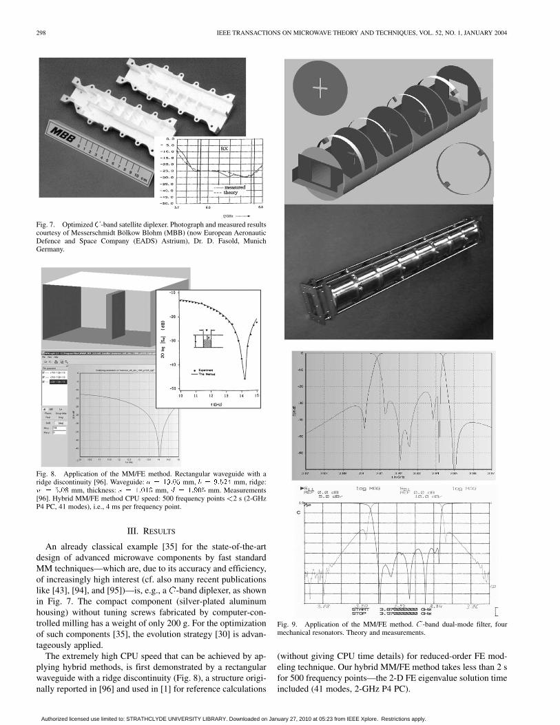
Fig. 9. Application of the MM/FE method. C-band dual-mode filter, fourmechanical resonators. Theory and measurements.
(without giving CPU time details) for reduced-order FE mod-eling technique. Our hybrid MM/FE method takes less than 2 sfor 500 frequency points—the 2-D FE eigenvalue solution timeincluded (41 modes, 2-GHz P4 PC).
Authorized licensed use limited to: STRATHCLYDE UNIVERSITY LIBRARY. Downloaded on January 27, 2010 at 05:23 from IEEE Xplore. Restrictions apply.

ARNDT et al.: FAST CAD AND OPTIMIZATION OF WAVEGUIDE COMPONENTS AND APERTURE ANTENNAS BY HYBRID MM/FE/MoM/FD METHODS 299
Fig. 10. Accuracy and dynamic range of the MM/FE method. OptimizedC-band waffle-iron filter. Built without tuning screws. Measured results(boldface return loss curve in small window) courtesy of Bosch Telecom(now TESAT Spacecom GmbH), F.-J. Goertz, D. Wolk, Backnang, Germany,and Dr. D. Schmitt, (now European Space Agency (ESA), Noordwijk, TheNetherlands). CPU speed < 0.1 s per frequency point, 2-GHz P4 PC, 152modes.
An illustration of the complexity of waveguide componentsdesigned by the MM/FE method is a typical -band eight-poledual-mode filter applied for space communications (see Fig. 9).The dual-mode circular waveguide filter of inner radius
mm consists of two rectangular input irises with roundedcorners, three cross-irises with rounded corners, and four setsof opposite 45 screws for coupling of the orthogonal modes.The filter has been optimized by using the procedure describedin [54] and built in our university machine shop. In spite of thefact that the 45 coupling screws have been modeled by squareposts, which leads to a slight frequency shift by a few megahertz,rather good agreement between measurements (tuning screwsremoved) and simulations may be stated.
The excellent accuracy, high dynamic range, and high CPUspeed achieved by the MM/FE method is demonstrated by anoptimized and measured -band waffle-iron filter (WR-229)(see Fig. 10).
The next example, a septum polarizer (Fig. 11) relates toa typical MM/FE application, where the ridge sections (i.e.,FE eigenvector sections) are directly connected to each other.Hence—as outlined in Section II—for the corresponding cou-pling coefficients, calculations via area integrals are preferredto line integrals. The dimensions are chosen according to [97],where cross-sectional field matching has been applied for thesolution of the eigenvalue problem [98], which is considerablymore time consuming than applying the MM/FE technique be-cause of the involved search algorithm in the MM eigenvaluesolution problem.
The MM/FE method extended for inclusion of typicalcoaxial feed structures (see Fig. 12) achieves the possibility
Fig. 11. Application of the MM/FE method for direct combination ofFE eigenvector sections. Septum polarizer, dimensions according to [97](waveguide a = b = 48:26 mm). Power split of square waveguide orthogonalmodes to rectangular waveguide output ports, H01 return loss, isolation, H10
return loss. Small window: Axial ratio. CPU time: 34 s, 500 frequency points:<0.1 s per frequency point (14 s for eigenvalue problem of the four ridgesections, 20-s MM dynamic calculation for the 500 frequency points), 2-GHzP4 PC, 120 modes.
Fig. 12. Extending the MM/FE method to coaxial structures. Typical feedelements for combline filters: direct post, loop, disc, slope, metal sheet coupling.
of the extremely fast CAD and optimization of combline andinterdigital filters/diplexers with rectangular post elements. Therectangular post structure can either be utilized for low-costfabrication by a computer-controlled milling technique (wherethe corresponding data file can be directly loaded from thegraphical output of the CAD and optimization tool) or the rect-angular structure can be converted into corresponding circularposts by applying, e.g., well-known formulas of identical char-acteristic impedances (square/circular rod between two plates).This yields good starting points for further optimizations byapplying, e.g., the MM/FD or MM/MoM methods for circularposts.
For accuracy verification, a simple directly coaxial-line-fedfour-resonator rectangular combline filter for 2.32-GHz mid-band frequency has been fabricated by a computer-controlledmilling technique without any tuning screws (see Fig. 13). Verygood agreement between theory and measurements, also for
Authorized licensed use limited to: STRATHCLYDE UNIVERSITY LIBRARY. Downloaded on January 27, 2010 at 05:23 from IEEE Xplore. Restrictions apply.

300 IEEE TRANSACTIONS ON MICROWAVE THEORY AND TECHNIQUES, VOL. 52, NO. 1, JANUARY 2004
Fig. 13. Milled rectangular combline filter for 2.32-GHz midband frequencywithout tuning screws. Dimensions (in millimeters): waveguide housinga = 22:816, b = 21:729; feed SMA, inner conductor height 4.5, distancewall to center first post 10.4, posts 8.928� 8.928, heights 20.35 (first) 19.96(second), distances (post-plane to post-plane) 20.47, 23.76. (Mesh refinementin post-section factor 5). CPU time: 20 s. 200 frequency points (fps) (0.1 s./fp),125 modes, 2-GHz P4 PC.
far-off selectivity, can be stated. For the MM/FE calculation,125 modes have been taken into account; the CPU speed is 0.1 sper frequency point on a 2-GHz P4 PC, which underlines, again,the efficiency of the hybrid MM/FE method also for this classof filters, making their optimization a straightforward task.
In order to also demonstrate the flexibility of the appliedMM/FE method for more complicated combline or interdigitalfilter applications, a cross-coupled rectangular combline filterhas been optimized for approximately 2.5-GHz midband fre-quency and 40-MHz passband bandwidth. The direct couplingis provided by electric irises, the negative cross-coupling be-tween resonators 4–1 is achieved by magnetic iris cross-cou-pling (Fig. 14).
Fig. 15 shows an example for the edge element MM/FEmethod (Fig. 2): a circular waveguide with inner dielectriccylinder of finite length. Reference values of [75] have beenused for comparison.
The application of the MM/MoM method for 3-D waveguidestructures is demonstrated in Fig. 16 with the example of aMagic T compensated by a post and an iris. The CPUspeedis approximately 8 s per frequency point on a 2-GHzP4 PC. Good agreement with reference calculations using the
Fig. 14. Application of the MM/FE method for multiports. Optimizedcross-coupled combline filter. Magnetic iris cross-coupling 1–4, electric iriscoupling 1 and 2, 2 and 3 folded, and 3 and 4.
Fig. 15. Circular waveguide (radius 7.544 mm) with centered dielectriccylinder (radius 1.886 mm) of finite length 3.772 mm. [75].
FD-TD method [100] and the MM/FE generalized scatteringmatrix separation (GSMS) technique [101]. In this way, alsorather complicated 3-D structures, such as waffle-iron filterswith round teeth [76], can be modeled .
Fig. 17 shows a slot array with 21 slots in the broadwaveguide wall according to [102]. The MM/MoM MLFMMmethod including the internal coupling provides results thatagree well with measurements reported in [102]. In the lowerpart of Fig. 17, results also obtained by an MM/MoM spec-tral-domain approach (SDA) [103] are presented.
The next example (Fig. 18) demonstrating the application ofthe MM/FD-TD method is a lateral coax feed with dielectric
Authorized licensed use limited to: STRATHCLYDE UNIVERSITY LIBRARY. Downloaded on January 27, 2010 at 05:23 from IEEE Xplore. Restrictions apply.

ARNDT et al.: FAST CAD AND OPTIMIZATION OF WAVEGUIDE COMPONENTS AND APERTURE ANTENNAS BY HYBRID MM/FE/MoM/FD METHODS 301
Fig. 16. Application of the hybrid MM/MoM method. Compensated Magic T:dimensions (in millimeters): waveguide 12.7� 25.4, l = 8:225, d = 3:175,k = 3:556, w = 8:382, t = 0:7937, p = 0, height of post element 12.7.Structure: triangular mesh. MM/MoM results, comparison with MM/FE [101]and FD-TD [100] results.
coating and additional post-compensation elements, comparedwith reported measurements [58]. The subgrid for this exampleis set up within the indicated frame (dashed–dotted lines),
Fig. 17. Application of the hybrid MM/MoM MLFMM method. Slot arraywith 21 slots of [102]. Comparison with measurements [102] and MoM SDAresults [103].
Fig. 18. Lateral coax feed of [56]. (a) Structure. (b) Geometrical dimensionsin millimeters, � = 1:9873, ideally conducting material (dark grey), dielectricmaterial (grey). (c) Return loss calculated by the present method (solid line)compared with reported measurements (crosses) [58].
hence, this area contains the combination of the subgrid withthe conformal technique [104], [105] for the post and feed el-ements (dark gray) and with the intersection approach for thedielectric coating (gray). This achieves a rather fast CPU speedas compared with standard FD methods: for the example shown,
Authorized licensed use limited to: STRATHCLYDE UNIVERSITY LIBRARY. Downloaded on January 27, 2010 at 05:23 from IEEE Xplore. Restrictions apply.

302 IEEE TRANSACTIONS ON MICROWAVE THEORY AND TECHNIQUES, VOL. 52, NO. 1, JANUARY 2004
Fig. 19. Three rectangular apertures according to [106], but in finiterectangular plate of size 100 mm� 100 mm. Aperture sizes: 22.8 mmcenter aperture, 15.7 mm � 7.7 mm lateral apertures, displacement 30 mmf = 12:5 GHz.
500 frequency points take approximately 360 s (2-GHz P4 PC).The application of the standard FD-TD method (with the samenumber of unknowns) would result in only approximately 20-dBreturn loss (not shown in Fig. 18). The calculated GSM allowsthe convenient combination with MM elements such as irisesfor the calculation of coax-fed waveguide filters.
An MM/FD method [64] has been successfully applied re-cently to the design of combline filters. With the MM/FD-TDmethod, the optimization of dielectric resonator filters withinreasonable time periods is also possible [12].
Fig. 19 demonstrates the application of the MM/MoMMLFMA techniques to three coupled radiating rectangularapertures according to [106], but within a finite plate, as shownin Fig. 3. For the MLFMA, 7105 unknowns, 336 groups, threelevels have been considered. A Cholesky pre-conditioner hasbeen applied. The storage requirement was 180 MB. Goodagreement with measurements [106] both for the -parametersand field pattern (provided in [106] up to 90 ) can be stated.
IV. CONCLUSION
Fast EM-based CAD tools yielding accurate optimized de-signs within adequately short respond times are highly desir-able. This goal is achieved by hybrid techniques, which typicallygo beyond the possibilities of single methods, by expandingthe capabilities and enhancing the efficiency. The described hy-brid methods advantageously combine the efficiency of the MMmethod with the flexibility of FE, FD, and MoM techniques.Typical application examples demonstrate their versatility andhigh calculation speed. The accuracy is verified by availablemeasurements and reference calculations.
REFERENCES
[1] J. E. Bracken, D.-K. Sun, and Z. J. Cendes, “S-domain methods for si-multaneous time and frequency characterization of electromagnetic de-vices,” IEEE Trans. Microwave Theory Tech., vol. 46, pp. 1277–1290,Sept. 1998.
[2] A. S. Rong, H. Yang, X. H. Chen, and A. Cangellaris, “Efficient FD-TDmodeling of irises/slots in microwave structures and its application tothe design of combline filters,” IEEE Trans. Microwave Theory Tech.,vol. 49, pp. 2266–2275, Dec. 2001.
[3] W. C. Chew, J.-M. Jin, C.-C. Lu, E. Michielssen, and J. M. Song, “Fastsolution methods in electromagmetics,” IEEE Trans. Antennas Prop-agat., vol. 45, pp. 533–543, Mar. 1997.
[4] J.-S. Zhao, W. C. Chew, C.-C. Lu, E. Michielssen, and J. Song, “Thin-stratified medium fast-multipole algorithm for microstrip structures,”IEEE Trans. Microwave Theory Tech., vol. 46, pp. 395–403, Apr. 1998.
[5] F. Ling, C.-F. Wang, and J.-M. Jin, “An efficient algorithm for analyzinglarge-scale microstrip structures using adaptive integral method com-bined with discrete complex-image method,” IEEE Trans. MicrowaveTheory Tech., vol. 48, pp. 832–839, May 2000.
[6] A. F. Peterson, S. L. Ray, and R. Mittra, Computational Methods forElectromagnetics. New York: IEEE Press, 1998.
[7] W. C. Chew, J.-M. Jin, E. Michielssen, and J. Song, Fast and EfficientAlgorithms in Computational Electromagnetics. Boston, MA: ArtechHouse, 2001.
[8] R. Coifman, V. Rokhlin, and S. Wandzura, “The fast multipole methodfor the wave equation: A pedestrian prescription,” IEEE Antennas Prop-agat. Mag., vol. 35, pp. 7–12, June 1996.
[9] E. Bleszynski, M. Bleszynski, and J. Jaroszevicz, “AIM: Adaptive in-tegral method for solving large-scale electromagnetic scattering prob-lems,” Radio Sci., vol. 31, pp. 1225–1251, Sept.–Oct. 1996.
[10] M. F. Gyure and M. A. Stalzer, “A prescription for the multilevelHelmholtz FMM,” IEEE Comput. Sci. Eng., vol. 5, pp. 35–47,July–Sept. 1998.
[11] R. Lotz and F. Arndt, “Locally conformed subgrid FD-FD techniquefor the analysis of 3D waveguide structures with curved metallic ob-jects,” in IEEE MTT-S Int. Microwave Symp. Dig., vol. 3, June 1999,pp. 1277–1280.
[12] F. Arndt, R. Lotz, and J. Ritter, “Advanced FD-TD techniques forthe CAD of microwave components,” Electromagnetics, vol. 23, pp.153–168, Feb.–Mar. 2003.
[13] G. A. Thiele and T. H. Newhouse, “A hybrid technique for combiningmoments methods with the geometrical theory of diffraction,” IEEETrans. Antennas Propagat., vol. AP-23, pp. 62–69, Jan. 1975.
[14] W. D. Burnside and P. H. Pathak, “A summary of hybrid solutions in-volving moment methods and GTD,” in Applications of the Method ofMoments to Electromagnetic Fields, B. J. Strait, Ed. St. Cloud, FL:SCEEE Press, 1980.
[15] J. J. H. Wang, Generalized Moment Methods in Electromag-netics. New York: Wiley, 1991.
[16] G. Tiberi, A. Monorchio, G. Manara, and R. Mittra, “Hybridizingasymptotic and numerically rigorous techniques for solving electro-magnetic scattering problems using the characteristics basis functions,”presented at the IEEE Int. Antennas and Propagation Symp., vol. 3,June 2003.
Authorized licensed use limited to: STRATHCLYDE UNIVERSITY LIBRARY. Downloaded on January 27, 2010 at 05:23 from IEEE Xplore. Restrictions apply.

ARNDT et al.: FAST CAD AND OPTIMIZATION OF WAVEGUIDE COMPONENTS AND APERTURE ANTENNAS BY HYBRID MM/FE/MoM/FD METHODS 303
[17] J. Liu and J. M. Jin, “A novel hybridization of higher order finiteelement and boundary integral methods for electromagnetic scatteringand radiation problems,” IEEE Trans. Antennas Propagat., vol. 49, pp.1794–1806, Dec. 2001.
[18] H. Rogier, F. Olyslager, and D. de Zutter, “A hybrid finite elementintegral equation approach for the eigenmode analysis of complexanisotropic dielectric waveguides,” Radio Sci., vol. 31, pp. 999–1010,July–Aug. 1996.
[19] W. C. Hahn, “A new method for the calculation of cavity resonators,” J.Appl. Phys., vol. 12, pp. 62–68, Jan. 1941.
[20] J. R. Whinnery and H. W. Jamieson, “Equivalent circuits for discontinu-ities in transmission lines,” Proc. IRE, vol. 32, pp. 98–116, Feb. 1944.
[21] P. J. B. Clarricoats and K. R. Slinn, “Numerical solution of waveguide-discontinuity problems,” Proc. Inst. Elect. Eng., vol. 114, pp. 878–886,July 1967.
[22] A. Wexler, “Solution of waveguide discontinuities by modal analysis,”IEEE Trans. Microwave Theory Tech., vol. MTT-15, pp. 508–517, Sept.1967.
[23] G. L. James, “Analysis and design of TE11-to-HE11 corrugatedcylindrical waveguide mode converters,” IEEE Trans. MicrowaveTheory Tech., vol. MTT-29, pp. 1059–1066, Oct. 1981.
[24] H. Patzelt and F. Arndt, “Double-plane steps in rectangular waveguideand their application for transformers, irises and filters,” IEEE Trans.Microwave Theory Tech., vol. MTT-30, pp. 771–777, May 1982.
[25] F. Arndt, D. Ellermann, H. W. Haeusler, and J. Strube, “Field theoryanalysis and numerical synthesis of symmetrical multiple-branch wave-guide couplers,” Frequenz, vol. 36, pp. 262–266, Oct. 1982.
[26] F. Arndt, J. Bornemann, D. Grauerholz, and R. Vahldieck, “Theory anddesign of low-insertion loss fin-line filters,” IEEE Trans. MicrowaveTheory Tech., vol. MTT-30, pp. 155–163, Feb. 1982.
[27] R. Vahldieck, J. Bornemann, F. Arndt, and D. Grauerholz, “Optimizedwaveguide E-plane metal insert filters for millimeter-wave applica-tions,” IEEE Trans. Microwave Theory Tech., vol. MTT-31, pp. 65–69,Jan. 1983.
[28] F. Arndt, B. Koch, H.-J. Orlok, and N. Schroeder, “Field theory designof rectangular waveguide broad-wall metal- insert slot couplers for mil-limeter-wave applications,” IEEE Trans. Microwave Theory Tech., vol.MTT-33, pp. 95–104, Feb. 1985.
[29] U. Tucholke, F. Arndt, and T. Wriedt, “Field theory design of squarewaveguide iris polarizers,” IEEE Trans. Microwave Theory Tech., vol.MTT-34, pp. 156–160, Jan. 1986.
[30] H. Schmiedel and F. Arndt, “Field theory design of rectangular wave-guide multiple-slot narrow wall couplers,” IEEE Trans. MicrowaveTheory Tech., vol. MTT-34, pp. 791–798, July 1986.
[31] J. Dittloff, F. Arndt, and D. Grauerholz, “Optimum design of waveguideE-plane stub-loaded phase shifters,” IEEE Trans. Microwave TheoryTech., vol. 36, pp. 583–587, Mar. 1988.
[32] J. Dittloff and F. Arndt, “Rigorous design of septate E-plane multi-plexers with printed circuit elements,” in IEEE MTT-S Int. MicrowaveSymp. Dig., New York, May 1988, pp. 431–434.
[33] , “Computer-aided design of slit-coupled H-plane T-junctiondiplexers with E-plane metal-insert filters,” IEEE Trans. MicrowaveTheory Tech., vol. 36, pp. 1833–1840, Dec. 1988.
[34] F. Alessandri, G. Bartolucci, and R. Sorrentino, “Admittance matrix for-mulation of waveguide discontinuity problems: Computer-aided designof branch-guide directional couplers,” IEEE Trans. Microwave TheoryTech., vol. 36, pp. 394–403, Feb. 1988.
[35] F. Arndt, J. Dittloff, U. Papziner, D. Fasold, N. Nathrath, and H. Wolf,“Rigorous field theory design of compact and lightweight broadbanddiplexers for satellite communication systems,” in Proc. 19th Eur. Mi-crowave Conf., London, U.K., Sept. 1989, pp. 1214–1219.
[36] R. Sorrentino, Ed., Numerical Methods for Passive Microwave and Mil-limeter Wave Structures. New York: IEEE Press, 1989.
[37] F. Arndt, T. Duschak, U. Papziner, and P. Rolappe, “Asymmetric iriscoupled cavity filters with stopband poles,” in IEEE MTT-S Int. Mi-crowave Symp. Dig., Dallas, TX, May 1990, pp. 215–218.
[38] U. Papziner and F. Arndt, “Field theoretical computer-aided design ofrectangular and circular iris coupled rectangular or circular waveguidecavity filters,” IEEE Trans. Microwave Theory Tech., vol. 41, pp.462–471, Feb. 1993.
[39] M. Guglielmi, G. Gheri, M. Calamia, and G. Pelosi, “Rigorousmultimode network representation of inductive steps,” IEEE Trans.Microwave Theory Tech., vol. 42, pp. 317–326, Feb. 1994.
[40] A. P. Orfanidis, G. A. Kyriacou, and J. N. Sahalos, “A mode-matchingtechnique for the study of circular and coaxial waveguide discontinu-ities based on closed-form coupling integrals,” IEEE Trans. MicrowaveTheory Tech., vol. 48, pp. 880–883, May 2000.
[41] F. Alessandri, M. Giordano, M. Guglielmi, G. Martirano, and F. Vitulli,“A new multiple-tuned six-port riblet-type directional coupler in rect-angular waveguide,” IEEE Trans. Microwave Theory Tech., vol. 51, pp.1441–1448, May 2003.
[42] J. Kocbach and K. Folgero, “Design procedure for waveguide filters withcross-couplings,” in IEEE MTT-S Int Microwave Symp. Dig., vol. 3, June2002, pp. 1449–1452.
[43] L. Accatino and M. Mongiardo, “Hybrid circuit-full-wave computer-aided design of a manifold multiplexers without tuning elements,” IEEETrans. Microwave Theory Tech., vol. 50, pp. 2044–2047, Sept. 2002.
[44] P. Matras, R. Bunger, and F. Arndt, “Modal scattering matrix of the gen-eral step discontinuity in elliptical waveguides,” IEEE Trans. MicrowaveTheory Tech., vol. 45, pp. 453–458, Mar. 1997.
[45] M. Mongiardo, P. Russer, C. Tomassoni, and L. Felsen, “Analysis ofN -furcation in elliptical waveguides via the generalized network formu-lation,” IEEE Trans. Microwave Theory Tech., vol. 47, pp. 2473–2478,Dec. 1999.
[46] E. Kühn and V. Hombach, “Computer-aided analysis of corrugated hornswith axial ring or ring-loaded radial slots,” in Proc. Int. Antennas Prop-agat. Conf., Norwich, U.K., Mar. 1983, pp. 293–296.
[47] K. Wolff, T. Wriedt, F. Arndt, and U. Tucholke, “Hybrid field designof square potter horns,” in Proc. Int. Antennas Propagat. Conf., York,U.K., Mar. 1987, pp. 210–213.
[48] T. Wriedt, K.-H. Wolff, F. Arndt, and U. Tucholke, “Rigorous hybridfield theoretic design of stepped rectangular waveguide mode convertersincluding the horn transitions into half-space,” IEEE Trans. AntennasPropagat., vol. 37, pp. 780–790, June 1989.
[49] K. Liu, C. A. Balanis, and C. R. Birtcher, “Analysis of pyramidal hornantennas using moment methods,” IEEE Trans. Antennas Propagat., vol.41, pp. 1379–1389, Oct. 1993.
[50] R. Bunger, R. Beyer, and F. Arndt, “Rigorous combined mode-matchingintegral equation analysis of horn antennas with arbitrary cross section,”IEEE Trans. Antennas Propagat., vol. 47, pp. 1641–1648, Nov. 1999.
[51] R. Beyer and F. Arndt, “Field theory design of circular waveguidedual-mode filters by a combined mode matching finite elementmethod,” in Eur. Microwave Conf. Symp. Dig., Cannes, France, Sept.1994, pp. 437–442.
[52] , “Efficient modal analysis of waveguide filters including the or-thogonal mode coupling elements by an MM/FE method ,” IEEE Mi-crowave Guided Wave Lett, vol. 5, pp. 1–3, Jan. 1995.
[53] J. R. Montejo-Garai and J. Zapata, “Full-wave design and realization ofmulticoupled dual-mode circular waveguide filters,” IEEE Trans. Mi-crowave Theory Tech., vol. 43, pp. 1290–1297, June 1995.
[54] F. Arndt, R. Beyer, J. M. Reiter, T. Sieverding, and T. Wolf,“Automated design of waveguide components using hybridmode-matching/numerical EM building blocks in optimization-orientedCAD frame-works—State-of-the-Art and recent advances,” IEEETrans. Microwave Theory Tech., vol. 45, pp. 747–760, May 1997.
[55] F. Arndt, R. Beyer, W. Hauth, D. Schmitt, and H. Zeh, “Cascaded widestop band waffle-iron filter designed with a MM/FE CAD method,” inEur. Microwave Conf. Symp. Dig., Munich, Germany, Oct. 1999, pp.186–189.
[56] F. Arndt and J. Brandt, “Fast hybrid MM/FE CAD tool for the design andoptimization of advanced evanescent mode filters ,” in Int. Microwavesand Optronics Symp. Dig., Stuttgart, Germany, May 2001, pp. 369–372.
[57] , “MM/FE CAD and optimization of rectangular combline filters,”in Eur. Microwave Conf. Symp. Dig., Milan, Italy, Sept. 2002, pp.335–338.
[58] J. Rubio, J. Arroyo, and J. Zapata, “Analysis of passive microwavecircuits by using a hybrid 2-D and 3-D finite-element mode-matchingmethod,” IEEE Trans. Microwave Theory Tech., vol. 47, pp. 1746–1749,Sept. 1999.
[59] R. Beyer and F. Arndt, “Efficient MM/FE GSMS technique for theCAD of broadband lateral coax feeds in rectangular waveguide,” inIEEE MTT-S Int. Microwave Symp. Dig., Boston, MA, June 2000, pp.109–112.
[60] D. Arena, M. Ludovico, G. Manara, and A. Monorchio, “Analysisof waveguide discontinuities using edge elements in a hybrid modematching/finite elements approach,” IEEE Microwave Wireless Comp.Lett., vol. 11, pp. 379–381, Sept. 2001.
Authorized licensed use limited to: STRATHCLYDE UNIVERSITY LIBRARY. Downloaded on January 27, 2010 at 05:23 from IEEE Xplore. Restrictions apply.

304 IEEE TRANSACTIONS ON MICROWAVE THEORY AND TECHNIQUES, VOL. 52, NO. 1, JANUARY 2004
[61] V. Crino, C. Tomassoni, and M. Mongiardo, “Line-integral formulationof the hybrid MM/FEM technique ,” in IEEE MTT-S Int. MicrowaveSymp. Dig., Seattle, WA, June 2002, pp. 2033–2036.
[62] F. Alimenti, P. Mezzanotte, L. Roselli, and R. Sorrentino, “Efficientanalysis of waveguide components by FDTD combined with time do-main modal expansion ,” IEEE Microwave Guided Wave Lett., vol. 5,pp. 351–353, Oct. 1995.
[63] M. Righi, M. Mongiardo, R. Sorrentino, and W. Hoefer, “Efficient TLMdiakoptics for separable structures ,” in IEEE MTT-S Int. MicrowaveSymp. Dig., vol. 1, Atlanta, GA, June 1993, pp. 425–428.
[64] R. Lotz and F. Arndt, “FD-FD GSM technique for the CAD and op-timization of combline filters,” in IEEE MTT-S Int. Microwave Symp.Dig., Phoenix, AZ, May 2001, pp. 1253–1256.
[65] F. Arndt and A. Enneking, “Hybrid MM/FE/MOM technique for wave-guide horn antennas and slot arrays,” in Proc. Int. Electromagnetics inAdvanced Applications Conf., Turin, Italy, Sept. 2001, pp. 569–572.
[66] F. Arndt, J. Brandt, and J. Ritter, “MM/FE/FD CAD method for the opti-mization of waveguide filters including structures of arbitrary shape andcoax feeds,” in Eur. Microwave Conf. Symp. Dig., London, U.K., Sept.2001, pp. 319–322.
[67] F. Arndt, J. Brandt, V. Catina, A. Enneking, and J. Ritter, “Fast hybridMM/FE/TransFE/MoM/FD CAD of waveguide components and aper-ture antennas,” in Proc. 18th Annu. Rev. Progress in Applied Computa-tional Electromagnetics, Monterey, CA, Mar. 2002, pp. 1-15–1-23.
[68] F. Arndt, “A CAD tool utilizing fast hybrid MM/FE/MOM/FD tech-niques ,” Microwave J., vol. 45, pp. 178–182, Sept. 2002.
[69] J. Strube and F. Arndt, “Rigorous hybrid-mode analysis of the transitionfrom rectangular waveguide to shielded dielectric image guide,” IEEETrans. Microwave Theory Tech., vol. MTT-33, pp. 391–401, May 1985.
[70] W. Schroeder and M. Guglielmi, “Boundary integral equation approachto multi-mode Y-matrix characterization of multi-ridged sections in cir-cular waveguide,” in IEEE MTT-S Int. Microwave Symp. Dig., San Fran-cisco, CA, June 1996, pp. 1849–1852.
[71] J. Jin, The Finite Element Method in Electromagnetics. New York:Wiley, 1993.
[72] O. C. Zienkievicz, The Finite Element Method. Berkshire, U.K.: Mc-Graw-Hill, 1977.
[73] Y. Saad, “Numerical methods for large eigenvalue problems,”in Algorithms and Architectures for Advanced Scientific Com-puting. Manchester, U.K.: Manchester Univ. Press, 1992.
[74] Z. J. Cendes and J. F. Lee, “The transfinite element method for modelingMMIC devices,” IEEE Trans. Microwave Theory Tech., vol. MTT-36,pp. 1639–1649, Dec. 1983.
[75] A. Joestingmeier and A. S. Omar, “Analysis of inhomogeneously filledcavities coupled to waveguides using the VIE formulation,” IEEE Trans.Microwave Theory Tech., vol. 41, pp. 1207–1214, June/July 1993.
[76] R. Bunger and F. Arndt, “Moment-method analysis of arbitrary 3DmetallicN -port waveguide structures,” IEEE Trans. Microwave TheoryTech., vol. 48, pp. 531–537, Apr. 2000.
[77] J. R. Mautz and R. F. Harrington, “A generalized network formulationfor aperture problems,” IEEE Trans. Antennas Propagat., vol. AP-24,pp. 870–873, Nov. 1976.
[78] H. Auda and R. F. Harrington, “A moment solution for waveguide junc-tion problems,” IEEE Trans. Microwave Theory Tech., vol. MTT-31, pp.515–520, July 1983.
[79] S. M. Rao, D. R. Wilton, and A. W. Glisson, “Electromagnetic scatteringby surfaces of arbitrary shape,” IEEE Trans. Antennas Propagat., vol.AP-30, pp. 409–418, May 1982.
[80] J. Ritter and F. Arndt, “A generalized 3D subgrid technique for the finite-difference time domain method,” in IEEE MTT-S Int Microwave Symp.Dig., vol. 3, June 1997, pp. 1563–1566.
[81] R. Lotz, J. Ritter, and F. Arndt, “3D subgrid technique for the finitedifference method in the frequency domain,” in IEEE MTT-S Int Mi-crowave Symp. Dig., vol. 3, June 1998, pp. 1739–1742.
[82] S. S. Zivanovic, K. S. Yee, and K. K. Mei, “A subgridding method for thetime-domain finite-difference method to solve maxwell’s equations,”IEEE Trans. Microwave Theory Tech., vol. 39, pp. 471–479, Mar. 1991.
[83] I. S. Kim and W. J. R. Hoefer, “A local mesh refinement algorithm for thetime domain finite difference method using Maxwell’s curl equations,”IEEE Trans. Microwave Theory Tech., vol. 38, pp. 812–815, June 1990.
[84] S. Kapoor, “Sub-cellular technique for finite-difference time-domainmethod,” IEEE Trans. Microwave Theory Tech., vol. 45, pp. 673–677,May 1997.
[85] S. Dey and R. Mittra, “A locally conformal finite-difference time-do-main (FD-TD) algorithm for modeling three-dimensional perfectlyconducting objects,” IEEE Microwave Guided Wave Lett., vol. 7, pp.273–275, Sept. 1997.
[86] N. Kaneda, B. Houshmand, and T. Itoh, “FDTD analysis of dielectricresonators with curved surfaces,” IEEE Trans. Microwave Theory Tech.,vol. 45, pp. 1645–1649, Sept. 1997.
[87] Y. Hua and T. K. Sarkar, “Matrix pencil method for estimating param-eters of exponentially damped/undamped sinusoids in noise,” IEEETrans. Acoust., Speech, Signal Processing, vol. 38, pp. 814–824, May1990.
[88] J. Ritter and F. Arndt, “Efficient FD-TD/matrix pencil method for thefull-wave scattering parameter analysis of waveguiding structures,”IEEE Trans. Microwave Theory Tech., vol. 44, pp. 2450–2456, Dec.1996.
[89] J. M. Song and W. C. Chew, “Multilevel fast-multipole algorithmfor solving combined field integral equations of electromagneticscattering,” Microwave Opt. Technol. Lett., vol. 10, no. 1, pp. 14–19,Sept. 1995.
[90] R. Bunger and F. Arndt, “MLFMM analysis of ridged waveguide horns,”in Proc. Millennium Antennas Propagation Conf., Davos, Switzerland,Apr. 2000, pp. 1418–1418.
[91] I. Rullhusen and F. Arndt, “MLFMA analysis of coupled rectangularapertures,” in Proc. Journees Int. de Nice sur les Antennes Conf., Nice,France, Nov. 2002, pp. 459–462.
[92] , “Efficient MLFMA analysis of coupled rectangular and circularapertures in a finite screen,” in IEEE MTT-S Int. Microwave Symp. Dig.,Philadelphia, PA, June 2003, pp. 1971–1974.
[93] , “MLFMA analysis of finite aperture arrays including reflector,”presented at the IEEE AP-S Int. Symp. Dig., Columbus, OH, June 2003,Paper 125.8.
[94] S. Amari, J. Bornemann, W. Menzel, and F. Alessandri, “Diplexer de-sign using pre-synthesized waveguide filters with strongly dispersive in-verters,” in IEEE MTT-S Int. Microwave Symp. Dig., Phoenix, AZ, May2001, pp. 1627–1630.
[95] T. Shen, K. A. Zaki, and T. G. Dolan, “Rectangular waveguide diplexerswith a circular waveguide common port,” IEEE Trans. MicrowaveTheory Tech., vol. 51, pp. 578–582, Feb. 2003.
[96] R. Mansour, R. S. K. Tong, and R. H. McPhie, “Simplified descriptionof the field distribution in finlines and ridge waveguides and its applica-tion to the analysis ofE-plane discontinuities,” IEEE Trans. MicrowaveTheory Tech., vol. 36, pp. 1825–1832, Dec. 1988.
[97] J. Bornemann and V. A. Labay, “Ridge waveguide polarizer with finiteand stepped thickness septum,” IEEE Trans. Microwave Theory Tech.,vol. 43, pp. 1782–1787, Aug. 1995.
[98] J. Borneman and F. Arndt, “Transverse resonance, standing wave, andresonator formulation of the ridge waveguide eigenvalue problem andits application to the design of E-plane finned waveguide filters,” IEEETrans. Microwave Theory Tech., vol. 38, pp. 1104–113, Aug. 1990.
[99] J. Uher, J. Bornemann, and U. Rosenberg, Waveguide Components forAntenna Feed Systems: Theory and CAD. Boston, MA: Artech House,1993.
[100] J. Ritter and F. Arndt, “Efficient FD-TD/matrix pencil method for thefull-wave scattering parameter analysis of waveguiding structures,”IEEE Trans. Microwave Theory Tech., vol. 44, pp. 2450–2456, Dec.1996.
[101] R. Beyer and F. Arndt, “Efficient MM/FE GSMS technique for theCAD of broadband lateral coax feeds in rectangular waveguide,” inIEEE MTT-S Int. Microwave Symp. Dig., Boston, MA, June 2000, pp.109–112.
[102] R. S. Elliott, “On the design of traveling-wave-fed longitudinal shuntslot arrays,” IEEE Trans. Antennas Propagat., vol. AP-27, pp. 717–720,Sept. 1979.
[103] A. Enneking, R. Beyer, and F. Arndt, “Rigorous analysis of large finitewaveguide slot arrays including the mutual internal and external higher-order mode coupling,” in IEEE AP-S Int. Symp. Dig., July 2000, pp.74–77.
[104] R. Lotz, J. Ritter, and F. Arndt, “3D subgrid technique for the finitedifference method in the frequency domain,” in IEEE MTT-S Int Mi-crowave Symp. Dig., vol. 3, June 1998, pp. 1739–1742.
[105] , “Locally conformed subgrid FD-FD technique for the analysis of3D waveguide structures with curved metallic objects,” in IEEE MTT-SInt Microwave Symp. Dig., vol. 3, June 1999, pp. 1277–1280.
[106] T. S. Bird, “Analysis of mutual coupling in the design of different-sizedrectangular waveguides,” IEEE Trans. Antennas Propagat., vol. 38, pp.166–172, Feb. 1990.
Authorized licensed use limited to: STRATHCLYDE UNIVERSITY LIBRARY. Downloaded on January 27, 2010 at 05:23 from IEEE Xplore. Restrictions apply.

ARNDT et al.: FAST CAD AND OPTIMIZATION OF WAVEGUIDE COMPONENTS AND APERTURE ANTENNAS BY HYBRID MM/FE/MoM/FD METHODS 305
Fritz Arndt (SM’83–F’93) received the Dipl.-Ing.,Dr.-Ing., and Habilitation degrees from the TechnicalUniversity of Darmstadt, Darmstadt, Germany.
From 1968 to 1972, he was a Research Associatewith the Technical University of Darmstadt. Since1972, he has been a Full Professor and Head ofthe Microwave Department, University of Bremen,Bremen, Germany. He has authored or coauthoredover 200 technical papers, mainly in the field of EMCAD of microwave and antenna components. Hisresearch interests include numerical methods for the
rigorous and fast CAD of waveguide, microwave, and millimeter-wave circuits,as well as of horn and array antennas.
Dr. Arndt is a member of the Berein Deutscher Elektroingerieure (VDE)and Nachrichten-Technische-Gesellschaft (NTG), Germany. He is a member ofthe Editorial Board of the IEEE TRANSACTIONS ON MICROWAVE THEORY AND
TECHNIQUES, and he has served on the Technical Program Committee (TPC) ofthe IEEE Microwave Theory and Techniques Society (IEEE MTT-S) Interna-tional Microwave Symposium and on the TPC of the IEEE European MicrowaveConference. From 1993 to 1996, he was chairman of the joint German IEEEMTT-S and the IEEE Antennas and Propagation Society (IEEE AP-S) chapter.He was the recipient of the 1970 NTG Outstanding Publications Award, the 1983A. F. Bulgin Award (together with three co-authors) presented by the Institutionof Radio and Electronic Engineers, and the 1986 Best Paper Award presented atthe Antenna Conference Journees Internationales des Antennes (JINA), Nice,France.
J. Brandt (M’03) was born in Bremen, Germany, in1969. He received the Dipl.-Ing. degree from the Uni-versity of Bremen, Bremen, Germany, in 1995.
From 1995 to 2000, he was a Research Associatewith the Department of High-Frequency Techniques,University of Bremen, where he was involved in thenumerical modeling of waveguide components with2-D and 3-D finite-element methods. Since 2001, hehas been a Research and Development Engineer withthe Microwave Innovation Group (MIG) GmbH &Co. KG, Bremen, Germany, where he develops new
efficient methods for PC-based simulation of waveguide components.
V. Catina (M’02) was born on August 26, 1976, inResita, Romania. He received the Engineering degreein telecommunication from the Technical Universityof Timisoara, Timisoara, Romania, and is currentlyworking towards the Ph.D. degree at the Universityof Bremen, Bremen, Germany.
J. Ritter (M’94) received the Dipl.-Ing. degree from the University of Bremen,Bremen, Germany, in 1992.
From 1992 to 1996, he was with the Microwave Department, University ofBremen, where he developed and applied mainly FD methods in the time andfrequency domain to the analysis and optimization of waveguide components,filters, and antennas. Since 1996, he has been with the Military Aircraft busi-ness unit, European Aeronautic Defence and Space Company (EADS), Bremen,Germany, where he is responsible for electromagnetic simulation in the areasof radar cross-sectional engineering, antenna installed performance prediction,EM compatibility, and lightning protection of aircraft.
I. Rullhusen was born in Bremen, Germany, in1970. He received the Intermediate Diploma ofelectrical engineering, Diploma degree (Dipl.-Ing.)of electrical engineering, and Ph.D. degree inelectrical engineering (Dr.-Ing.) from the Universityof Bremen, Bremen, Germany, in 1992, 1995, and1999, respectively, and the Intermediate Diplomaof industrial engineering and Diploma degree ofindustrial engineering (Dipl.-Wirt.-Ing.) from theOpen University of Hagen, Hagen, Germany, in1998 and 2002, respectively.
Since 1995, he has been with the Institut für Telekommunikation undHochfrequenztechnik (ITH), University of Bremen. His current researchinterests include wavelet and fast integral methods (FMM, AIM) in electro-magnetics for different applications.
J. Dauelsberg was born in Delmenhorst, Germany, in1966. He received the Dipl.-Ing. degree in electricalengineering from the University of Bremen, Bremen,Germany, in 2002.
Since then he has been with the Microwave In-novation Group (MIG) GmbH & Co. KG, Bremen,Germany, where he develops software for microwaveanalysis and CAD programs. He has also been in-volved with the Microwave Department, Universityof Bremen. His research interests are currently re-lated to the CAD of passive waveguide components.
U. Hilgefort was born in Cloppenburg, Oldenburg,Germany, in 1969. He received the Dipl.-Ing. degreein electrical engineering from the University ofBremen, Bremen, Germany, in 2002.
Since then he has been with the Microwave In-novation Group (MIG) GmbH & Co. KG, Bremen,Germany. His research activities are focused on CADtechniques of passive waveguide components basedon the finite-element method.
W. Wessel was born in Oldenburg, Germany, in1968. He received the Dipl.-Ing. degree in electricalengineering from the University of Bremen, Bremen,Germany, in 1996.
From 1996 to 2000, he was with the MicrowaveDepartment, University of Bremen. Since then, hehas been with the Microwave Innovation Group(MIG) GmbH & Co. KG, Bremen, Germany, wherehe develops software for microwave analysis andCAD programs. His current research interests arerelated to the CAD of waveguide components and
antenna feed systems using the MM method and MoM.
Authorized licensed use limited to: STRATHCLYDE UNIVERSITY LIBRARY. Downloaded on January 27, 2010 at 05:23 from IEEE Xplore. Restrictions apply.

专注于微波、射频、天线设计人才的培养 易迪拓培训 网址:http://www.edatop.com
射 频 和 天 线 设 计 培 训 课 程 推 荐
易迪拓培训(www.edatop.com)由数名来自于研发第一线的资深工程师发起成立,致力并专注于微
波、射频、天线设计研发人才的培养;我们于 2006 年整合合并微波 EDA 网(www.mweda.com),现
已发展成为国内最大的微波射频和天线设计人才培养基地,成功推出多套微波射频以及天线设计经典
培训课程和 ADS、HFSS 等专业软件使用培训课程,广受客户好评;并先后与人民邮电出版社、电子
工业出版社合作出版了多本专业图书,帮助数万名工程师提升了专业技术能力。客户遍布中兴通讯、
研通高频、埃威航电、国人通信等多家国内知名公司,以及台湾工业技术研究院、永业科技、全一电
子等多家台湾地区企业。
易迪拓培训课程列表:http://www.edatop.com/peixun/rfe/129.html
射频工程师养成培训课程套装
该套装精选了射频专业基础培训课程、射频仿真设计培训课程和射频电
路测量培训课程三个类别共 30 门视频培训课程和 3 本图书教材;旨在
引领学员全面学习一个射频工程师需要熟悉、理解和掌握的专业知识和
研发设计能力。通过套装的学习,能够让学员完全达到和胜任一个合格
的射频工程师的要求…
课程网址:http://www.edatop.com/peixun/rfe/110.html
ADS 学习培训课程套装
该套装是迄今国内最全面、最权威的 ADS 培训教程,共包含 10 门 ADS
学习培训课程。课程是由具有多年 ADS 使用经验的微波射频与通信系
统设计领域资深专家讲解,并多结合设计实例,由浅入深、详细而又
全面地讲解了 ADS 在微波射频电路设计、通信系统设计和电磁仿真设
计方面的内容。能让您在最短的时间内学会使用 ADS,迅速提升个人技
术能力,把 ADS 真正应用到实际研发工作中去,成为 ADS 设计专家...
课程网址: http://www.edatop.com/peixun/ads/13.html
HFSS 学习培训课程套装
该套课程套装包含了本站全部 HFSS 培训课程,是迄今国内最全面、最
专业的HFSS培训教程套装,可以帮助您从零开始,全面深入学习HFSS
的各项功能和在多个方面的工程应用。购买套装,更可超值赠送 3 个月
免费学习答疑,随时解答您学习过程中遇到的棘手问题,让您的 HFSS
学习更加轻松顺畅…
课程网址:http://www.edatop.com/peixun/hfss/11.html
`

专注于微波、射频、天线设计人才的培养 易迪拓培训 网址:http://www.edatop.com
CST 学习培训课程套装
该培训套装由易迪拓培训联合微波 EDA 网共同推出,是最全面、系统、
专业的 CST 微波工作室培训课程套装,所有课程都由经验丰富的专家授
课,视频教学,可以帮助您从零开始,全面系统地学习 CST 微波工作的
各项功能及其在微波射频、天线设计等领域的设计应用。且购买该套装,
还可超值赠送 3 个月免费学习答疑…
课程网址:http://www.edatop.com/peixun/cst/24.html
HFSS 天线设计培训课程套装
套装包含 6 门视频课程和 1 本图书,课程从基础讲起,内容由浅入深,
理论介绍和实际操作讲解相结合,全面系统的讲解了 HFSS 天线设计的
全过程。是国内最全面、最专业的 HFSS 天线设计课程,可以帮助您快
速学习掌握如何使用 HFSS 设计天线,让天线设计不再难…
课程网址:http://www.edatop.com/peixun/hfss/122.html
13.56MHz NFC/RFID 线圈天线设计培训课程套装
套装包含 4 门视频培训课程,培训将 13.56MHz 线圈天线设计原理和仿
真设计实践相结合,全面系统地讲解了 13.56MHz线圈天线的工作原理、
设计方法、设计考量以及使用 HFSS 和 CST 仿真分析线圈天线的具体
操作,同时还介绍了 13.56MHz 线圈天线匹配电路的设计和调试。通过
该套课程的学习,可以帮助您快速学习掌握 13.56MHz 线圈天线及其匹
配电路的原理、设计和调试…
详情浏览:http://www.edatop.com/peixun/antenna/116.html
我们的课程优势:
※ 成立于 2004 年,10 多年丰富的行业经验,
※ 一直致力并专注于微波射频和天线设计工程师的培养,更了解该行业对人才的要求
※ 经验丰富的一线资深工程师讲授,结合实际工程案例,直观、实用、易学
联系我们:
※ 易迪拓培训官网:http://www.edatop.com
※ 微波 EDA 网:http://www.mweda.com
※ 官方淘宝店:http://shop36920890.taobao.com
专注于微波、射频、天线设计人才的培养
官方网址:http://www.edatop.com 易迪拓培训 淘宝网店:http://shop36920890.taobao.com