Embed Size (px)
Citation preview
SERI
ES20
08
SPEEDYSCAF®
FALSEWORK
PROTECTIVE SYSTEMS
ROLLING TOWERS
EVENT SYSTEM
ACCESSORIES
ALLROUND® SCAFFOLDING
LADDERS AND STAIRTOWERS
ContentsIntroduction andkey features 2
15 kN/m2 tower 3
10 kN/m2 towers 4
Capacity choice andsafety guide 5
Loading tower erectionguidance 6
Loading gate erectionguidance 7
UpdateLoading towersand gate systems
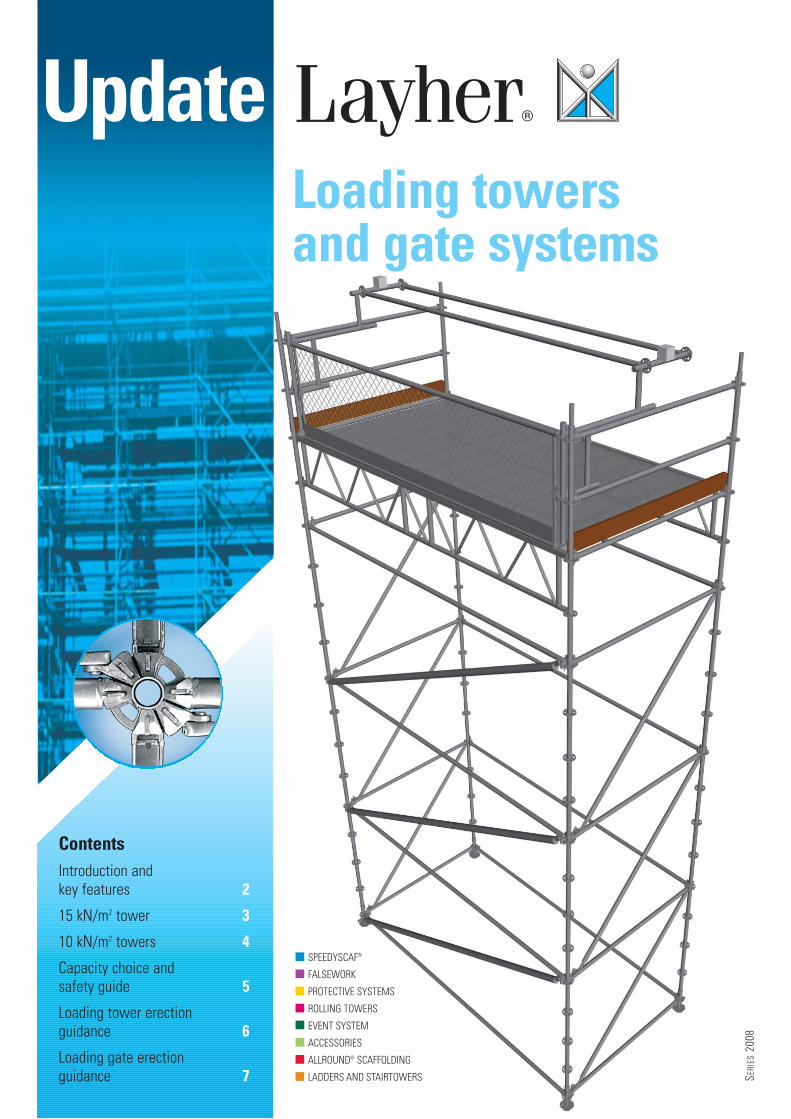
The Layher range of loading towers will allow more efficient
use of your plant and workforce, saving you time and money.
With over 50% more load carrying capacity than conventional
towers and requiring 50% less parts and reduced labour time,
the Layher range has a massive capacity of up to 15 kN/m2.
Importantly, this excellent loading capacity can be achieved
from standard Layher Allround® parts – enhancing component
versatility and maximising cost effectiveness – simply offering you more possibilities.
Design Every aspect of the Layher loading tower and gate range is the result of
meticulous analysis and design input. From ease of erection and dismantling, to ensuring
the maximum possible working area is available – and with simplicity of handling a key
consideration – every installation benefits from a commitment to design and testing that is
at the heart of Layher’s 60 years’ success.
Manufacture From material specification to testing procedures and comprehensive
traceability, every original Layher component is guaranteed to simplify use and maximise
effectiveness. With a commitment to combining high strength with light weight, all Layher
loading tower and gate systems leave our factory ready for the most demanding of
installations.
Safety The Layher commitment to safety is paramount with every aspect of design and
manufacture and is fully echoed in
the range of training courses and
the installation guidance available
to all users. Full equipment
compliance with appropriate
standards – benefiting from close
and established working
relationships with the leading
organisations in the field – helps to
put safe erection, use and
dismantling at the heart of
every installation.
Support The well-established
Layher UK office in Letchworth,
fully supported by our head office in
Germany, ensures the support that
one would expect of a leader in the
industry is available to users of every
Layher system. This applies directly
to the range of loading towers and
gates and can include a list of
services from site visits to working
drawings and from installation
advice to training. With ongoing
access to our extensive experience,
we believe our back up and support
capability is second to none.
Massive capacitywith a host offeatures
Provensystemsfrom thenumber 1in Europe
PAGE
2
Key features� More material available for use when it’s
needed, where it’s needed.
� Constructed entirely from Layher parts,with no investment required for special,bespoke components.
� All parts usable in other scaffoldingapplications, maximising versatility.
� Wide tower dimensions – up to 4.14 m –provides maximum space and simplifieslarge, awkward load movement.
� Less material and erection time meansgreater workforce productivity andreduced down time.
� Design overcomes potentialcomplications of conventional tube andfitting towers.
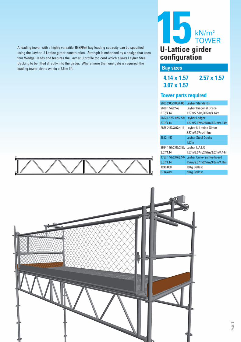
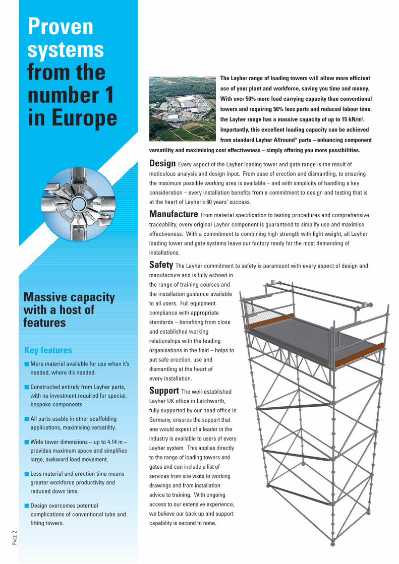
4.14 x 1.573.07 x 1.57
2.57 x 1.57
15Bay sizes
kN/m2
TOWERU-Lattice girderconfiguration
A loading tower with a highly versatile 15 kN/m2 bay loading capacity can be specifiedusing the Layher U-Lattice girder construction. Strength is enhanced by a design that usesfour Wedge Heads and features the Layher U profile top cord which allows Layher SteelDecking to be fitted directly into the girder. Where more than one gate is required, theloading tower pivots within a 2.5 m lift.
PAGE
3
Tower parts required2603.2.00/3.00/4.00 Layher Standards2620.1.57/2.57/ Layher Diagonal Brace3.07/4.14 1.57m/2.57m/3.07m/4.14m2607.1.57/2.07/2.57/ Layher Ledger3.07/4.14 1.57m/2.07m/2.57m/3.07m/4.14m2656.2.57/3.07/4.14 Layher U-Lattice Girder
2.57m/3.07m/4.14m3812.1.57 Layher Steel Decks
1.57m2634.1.57/2.07/2.57/ Layher L.A.L.O3.07/4.14 1.57m/2.07m/2.57m/3.07m/4.14m1757.1.57/2.07/2.57/ Layher UniversalToe board3.07/4.14 1.57m/2.07m/2.57m/3.07m/4.14m1249.000 10Kg Ballast0714.419 20Kg Ballast
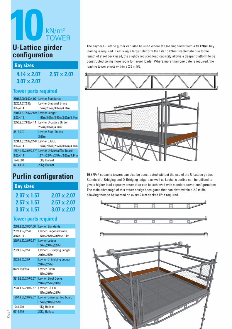
10 kN/m2
TOWERU-Lattice girderconfiguration
4.14 x 2.073.07 x 2.07
2.57 x 2.07
2.07 x 1.572.57 x 1.573.07 x 1.57
2.07 x 2.072.57 x 2.073.07 x 2.07
The Layher U-Lattice girder can also be used where the loading tower with a 10 kN/m2 bayloading is required. Featuring a larger platform than its 15 kN/m2 stablemate due to thelength of steel deck used, the slightly reduced load capacity allows a deeper platform to beconstructed giving more room for larger loads. Where more than one gate is required, theloading tower pivots within a 2.5 m lift.
Bay sizes
Purlin configuration
Bay sizes
PAGE
4
Tower parts required2603.2.00/3.00/4.00 Layher Standards2620.1.57/2.57/ Layher Diagonal Brace3.07/4.14 1.57m/2.57m/3.07m/4.14m2607.1.57/2.07/2.57/ Layher Ledger3.07/4.14 1.57m/2.07m/2.57m/3.07m/4.14m2656.2.57/3.07/4.14 Layher U-Lattice Girder
2.57m/3.07m/4.14m3812.2.07 Layher Steel Decks
2.07m2634.1.57/2.07/2.57/ Layher L.A.L.O3.07/4.14 1.57m/2.07m/2.57m/3.07m/4.14m1757.1.57/2.07/2.57/ Layher Universal Toe board3.07/4.14 1.57m/2.07m/2.57m/3.07m/4.14m1249.000 10Kg Ballast0714.419 20Kg Ballast
Tower parts required2603.2.00/3.00/4.00 Layher Standards2620.1.57/2.57/ Layher Diagonal Brace3.07/4.14 1.57m/2.57m/3.07m/4.14m2607.1.57/2.07/2.57 Layher Ledger
1.57m/2.07m/2.57m2624.2.07/2.57 Layher U-Bridging Ledger
2.07m/2.57m2625.2.07/2.57 Layher O-Bridging Ledger
2.07m/2.57m0721.383/384 Layher Purlin
1.57m/2.07m3812.2.07/2.57/3.07 Layher Steel Decks
2.07m/2.57m/3.07m2634.1.57/2.07/2.57 Layher L.A.L.O
1.57m/2.07m/2.57m1757.1.57/2.07/2.57 Layher Universal Toe board
1.57m/2.07m/2.57m1249.000 10Kg Ballast0714.419 20Kg Ballast
10 kN/m2 capacity towers can also be constructed without the use of the U-Lattice girder.Standard U-Bridging and O-Bridging ledgers as well as Layher’s purlins can be utilised togive a higher load capacity tower than can be achieved with standard tower configurations.The main advantage of this tower design sees gates that can pivot within a 2.0 m lift,allowing them to be located on every 2.0 m decked lift if required.
Correctly assembled, Layher loading towers and gates will provide years of reliable and effectiveperformance. As with all equipment, safety is paramount particularly with regard to thefollowing key factors – • Caution should be taken during assembly, alteration and dismantling of all Layher Allround®
scaffolding to ensure there is no risk of falls. Scaffolding assembly work should be performedto avoid the risk of falls as far as possible and to ensure that the residual risk is minimised.Assembly situations where there is a risk of falls are indicated in equipment instructions.
• Wedges must be hammered home immediately after assembly of the components using a 500 gmetal hammer until the blow bounces off.
• The wedge couple must be hammered tight using a 500 g metal hammer until the blow bouncesoff. Screw couplers must be tightened with a 50 Nm torque.
• Scaffolding must only be erected on sufficiently strong surfaces. Before assembling LayherAllround® structures, the surface must be checked for sufficient load-bearing capacity. Suitableload-distributing bases must be selected.
• The maximum spindle extension lengths must not be exceeded. One-sided positioning of thebase plate can cause excessive stresses in its cross-section and collapse of the scaffolding.
• Anchoring must be installed continually as scaffolding assembly progresses. In the case offree-standing structures, the maximum ratios of height to width must not be exceeded. Ifnecessary, stability must be assured by ballasting or bracing.
• Decks must be prevented from being lifted out by lift-off preventers. Only the temporary boardsintended for this purpose may be used here, in compliance with their maximum span andloading capacity.
• No personal or loose objects may be on rolling towers when these are being moved. Thewheels of the mobile tower must be locked unless the tower is being moved. Mobile towersmay only be used on flat surfaces.
Please note that with Allround®
scaffolding of steel the followingtwo variants must bedistinguished –
Safety first
Widechoice ofcapacities
PAGE
5
K2000+ – made starting 2000
Variant II – made until 1999
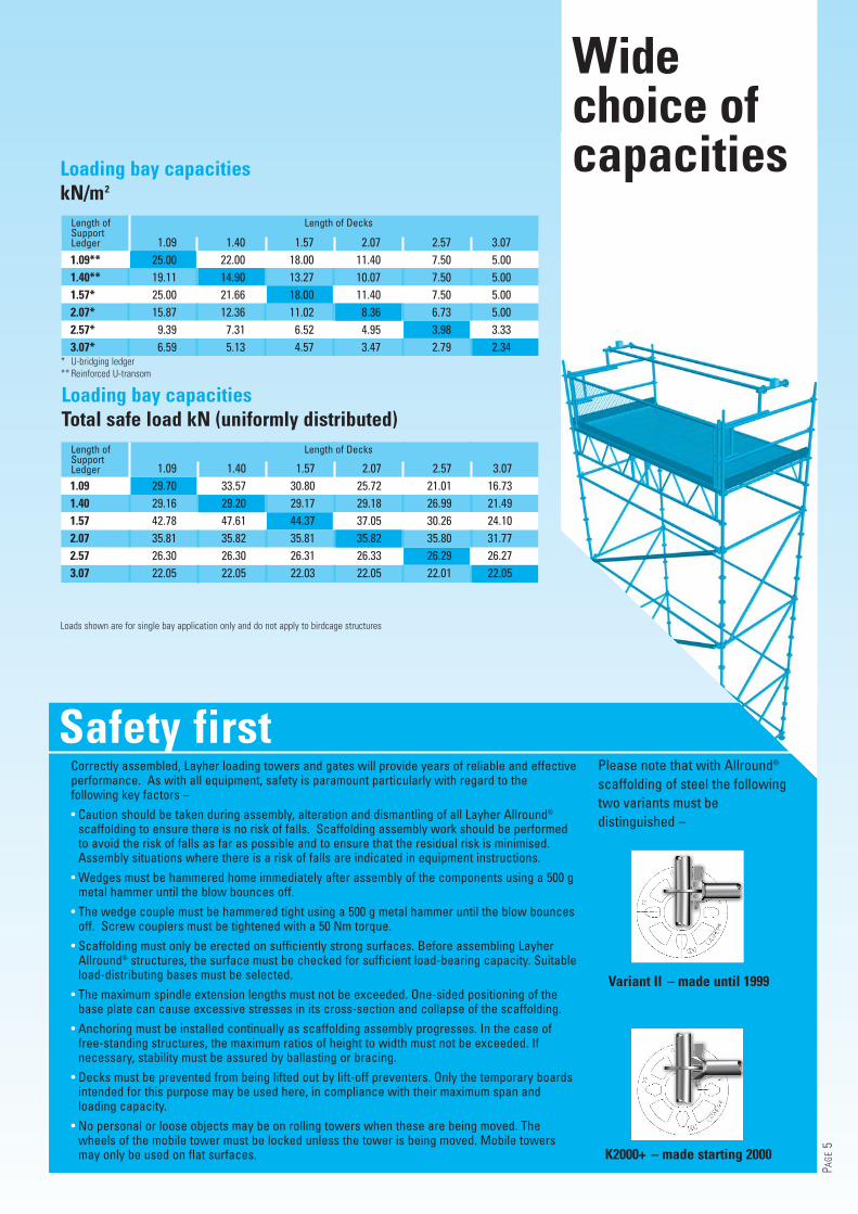
Loading bay capacitieskN/m2
Length of Length of DecksSupportLedger
* U-bridging ledger** Reinforced U-transom
Loading bay capacitiesTotal safe load kN (uniformly distributed)
Length of Length of DecksSupportLedger
Loads shown are for single bay application only and do not apply to birdcage structures
1.09 1.40 1.57 2.07 2.57 3.071.09** 25.00 22.00 18.00 11.40 7.50 5.001.40** 19.11 14.90 13.27 10.07 7.50 5.001.57* 25.00 21.66 18.00 11.40 7.50 5.002.07* 15.87 12.36 11.02 8.36 6.73 5.002.57* 9.39 7.31 6.52 4.95 3.98 3.333.07* 6.59 5.13 4.57 3.47 2.79 2.34
1.09 1.40 1.57 2.07 2.57 3.071.09 29.70 33.57 30.80 25.72 21.01 16.731.40 29.16 29.20 29.17 29.18 26.99 21.491.57 42.78 47.61 44.37 37.05 30.26 24.102.07 35.81 35.82 35.81 35.82 35.80 31.772.57 26.30 26.30 26.31 26.33 26.29 26.273.07 22.05 22.05 22.03 22.05 22.01 22.05
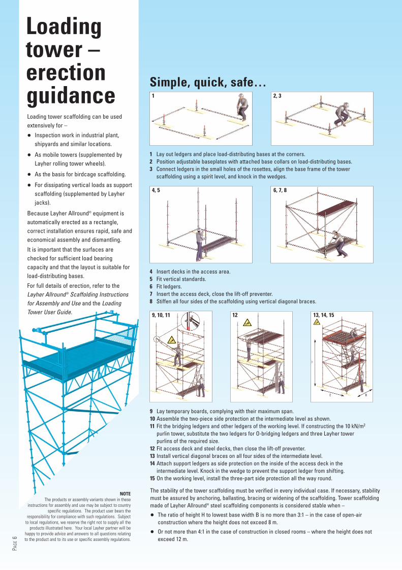
9 Lay temporary boards, complying with their maximum span.10 Assemble the two-piece side protection at the intermediate level as shown.11 Fit the bridging ledgers and other ledgers of the working level. If constructing the 10 kN/m2
purlin tower, substitute the two ledgers for O-bridging ledgers and three Layher towerpurlins of the required size.
12 Fit access deck and steel decks, then close the lift-off preventer.13 Install vertical diagonal braces on all four sides of the intermediate level.14 Attach support ledgers as side protection on the inside of the access deck in the
intermediate level. Knock in the wedge to prevent the support ledger from shifting.15 On the working level, install the three-part side protection all the way round.
1 Lay out ledgers and place load-distributing bases at the corners.2 Position adjustable baseplates with attached base collars on load-distributing bases.3 Connect ledgers in the small holes of the rosettes, align the base frame of the tower
scaffolding using a spirit level, and knock in the wedges.
4 Insert decks in the access area.5 Fit vertical standards.6 Fit ledgers.7 Insert the access deck, close the lift-off preventer.8 Stiffen all four sides of the scaffolding using vertical diagonal braces.
Simple, quick, safe…
Loading tower scaffolding can be usedextensively for –
• Inspection work in industrial plant,shipyards and similar locations.
• As mobile towers (supplemented byLayher rolling tower wheels).
• As the basis for birdcage scaffolding.
• For dissipating vertical loads as supportscaffolding (supplemented by Layherjacks).
Because Layher Allround® equipment isautomatically erected as a rectangle,correct installation ensures rapid, safe andeconomical assembly and dismantling.
It is important that the surfaces arechecked for sufficient load bearingcapacity and that the layout is suitable forload-distributing bases.
For full details of erection, refer to theLayher Allround® Scaffolding Instructionsfor Assembly and Use and the LoadingTower User Guide.
Loadingtower –erectionguidance
PAGE
6
NOTEThe products or assembly variants shown in these
instructions for assembly and use may be subject to countryspecific regulations. The product user bears the
responsibility for compliance with such regulations. Subjectto local regulations, we reserve the right not to supply all the
products illustrated here. Your local Layher partner will behappy to provide advice and answers to all questions relatingto the product and to its use or specific assembly regulations.
The stability of the tower scaffolding must be verified in every individual case. If necessary, stabilitymust be assured by anchoring, ballasting, bracing or widening of the scaffolding. Tower scaffoldingmade of Layher Allround® steel scaffolding components is considered stable when –
• The ratio of height H to lowest base width B is no more than 3:1 – in the case of open-airconstruction where the height does not exceed 8 m.
• Or not more than 4:1 in the case of construction in closed rooms – where the height does notexceed 12 m.
1 2, 3
4, 5 6, 7, 8
9, 10, 11 12 13, 14, 15
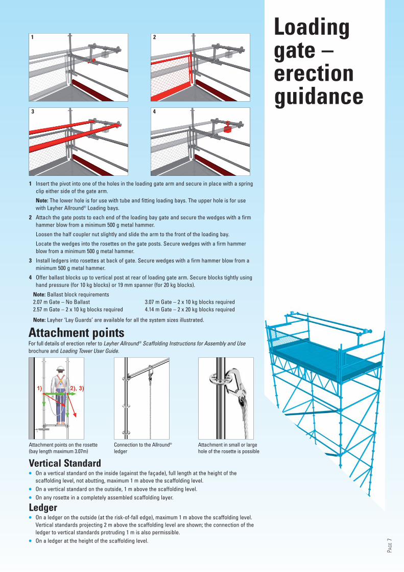
1 Insert the pivot into one of the holes in the loading gate arm and secure in place with a springclip either side of the gate arm.
Note: The lower hole is for use with tube and fitting loading bays. The upper hole is for usewith Layher Allround® Loading bays.
2 Attach the gate posts to each end of the loading bay gate and secure the wedges with a firmhammer blow from a minimum 500 g metal hammer.
Loosen the half coupler nut slightly and slide the arm to the front of the loading bay.
Locate the wedges into the rosettes on the gate posts. Secure wedges with a firm hammerblow from a minimum 500 g metal hammer.
3 Install ledgers into rosettes at back of gate. Secure wedges with a firm hammer blow from aminimum 500 g metal hammer.
4 Offer ballast blocks up to vertical post at rear of loading gate arm. Secure blocks tightly usinghand pressure (for 10 kg blocks) or 19 mm spanner (for 20 kg blocks).
Note: Ballast block requirements2.07 m Gate – No Ballast2.57 m Gate – 2 x 10 kg blocks required
3.07 m Gate – 2 x 10 kg blocks required4.14 m Gate – 2 x 20 kg blocks required
Attachment pointsFor full details of erection refer to Layher Allround® Scaffolding Instructions for Assembly and Usebrochure and Loading Tower User Guide.
Vertical Standard• On a vertical standard on the inside (against the façade), full length at the height of the
scaffolding level, not abutting, maximum 1 m above the scaffolding level.
• On a vertical standard on the outside, 1 m above the scaffolding level.
• On any rosette in a completely assembled scaffolding layer.
Ledger• On a ledger on the outside (at the risk-of-fall edge), maximum 1 m above the scaffolding level.
Vertical standards projecting 2 m above the scaffolding level are shown; the connection of theledger to vertical standards protruding 1 m is also permissible.
• On a ledger at the height of the scaffolding level.
Note: Layher ‘Lay Guards’ are available for all the system sizes illustrated.
PAGE
7
3 4
1 2
Attachment points on the rosette(bay length maximum 3.07m)
Connection to the Allround®
ledgerAttachment in small or largehole of the rosette is possible
Loadinggate –erectionguidance
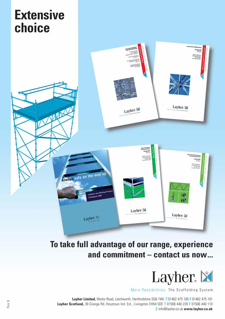
To take full advantage of our range, experienceand commitment – contact us now...
Layher Limited, Works Road, Letchworth, Hertfordshire SG6 1WL T 01462 475 100 F 01462 475 101Layher Scotland, 38 Grange Rd, Houstoun Ind. Est., Livingston EH54 5DE T 01506 440 220 F 01506 440 110
E [email protected] www.layher.co.ukPAGE
8
Extensivechoice