Embed Size (px)
Citation preview

1
KV CBCT ImagingPart I
Rabih Hammoud, MS, DABRHenry Ford Health System, Detroit, MI
Hamad Medical Corp. Doha, Qatar Detroit vs. Doha
2D Images
Learning objective:
The objective of this educational session
is to review KV-CBCT and MV-CBCT
imaging systems for daily localization
Outline1. Commissioning, image quality, dose,
registration process, and acquisition modes
2. Clinical integration 3. QA, stability over time, and downtime4. Standard clinical applications5. Novel clinical applications 6. Technology evolution and future directions

2
3D kV Imaging
Siemens Artiste™KVision
Varian Trilogy OBI® Novalis Tx™
Elekta Synergy™VolumeView Elekta Axesse™
What’s CBCT?
� On Board Imager CBCT acquires projections of a patient,
� Send them to a reconstruction application, and then returns a 3D image
� In the 3D/3D Match workspace, the CBCT images can be registered to the reference images, either manually or automatically, using a 3D mutual information algorithm.
Why CBCT?� Advances in treatment planning and
delivery systems allow for higher doses to target and lower dose to normal tissue
� With the resulting steep dose gradients, motion management ( inter and intra-fraction) becomes more critical
� Tumors often not visible in 2D images � Role of CBCT is to help reduce
interfractional motion and try to assess patient status ( tumor evaluation, adaptive planning, ..)
Volume = 4/3πr3
Small margin reduction (5mm) decreases the volume of an orange by 1/2

3
CBCT work Flow
� Data Preparation� Planning CT with structure set� Isocenter information� Send via Record Verify System
� Workflow� Select patient� Extend arms/gantry starting point� Imaging parameters� Acquire/reconstruct CBCT� Align (bony, soft tissue, VOI)� Apply shifts and record� Post shifts?� Treat
� Tolerated difference between the planning CT and CBCT depends on image quality, image registration, internal organ motion, margin definitions, user experience which are clinic and anatomical site dependent
Intra-fraction Prostate Motion
Langen et al. IJROBP 71(4):1084-1090, 2008
What can we do to decrease intra-fraction motion?
• Acquisition time (scan modes)
• Reconstruction time
• Matching (ROI, Intensity range, automatic/manual)
• Treatment time (RapidArc?)
Elekta Synergy™
� conventional x-ray tube mounted on a retractable arm extends from the accelerator gantry’s drum structure
� A 41×41 cm2 flat-panel x-ray detector is mounted opposite the kV tube at a gantry position of −90° in IEC coordinates
� The X-ray tube is powered by a high-frequency generator, operates ( 60-150 kVp) Novalis Tx™
Varian Trilogy OBI®
Full Fan Scan
Half Scan vs.
Full Scan
Half Fan Scan
4
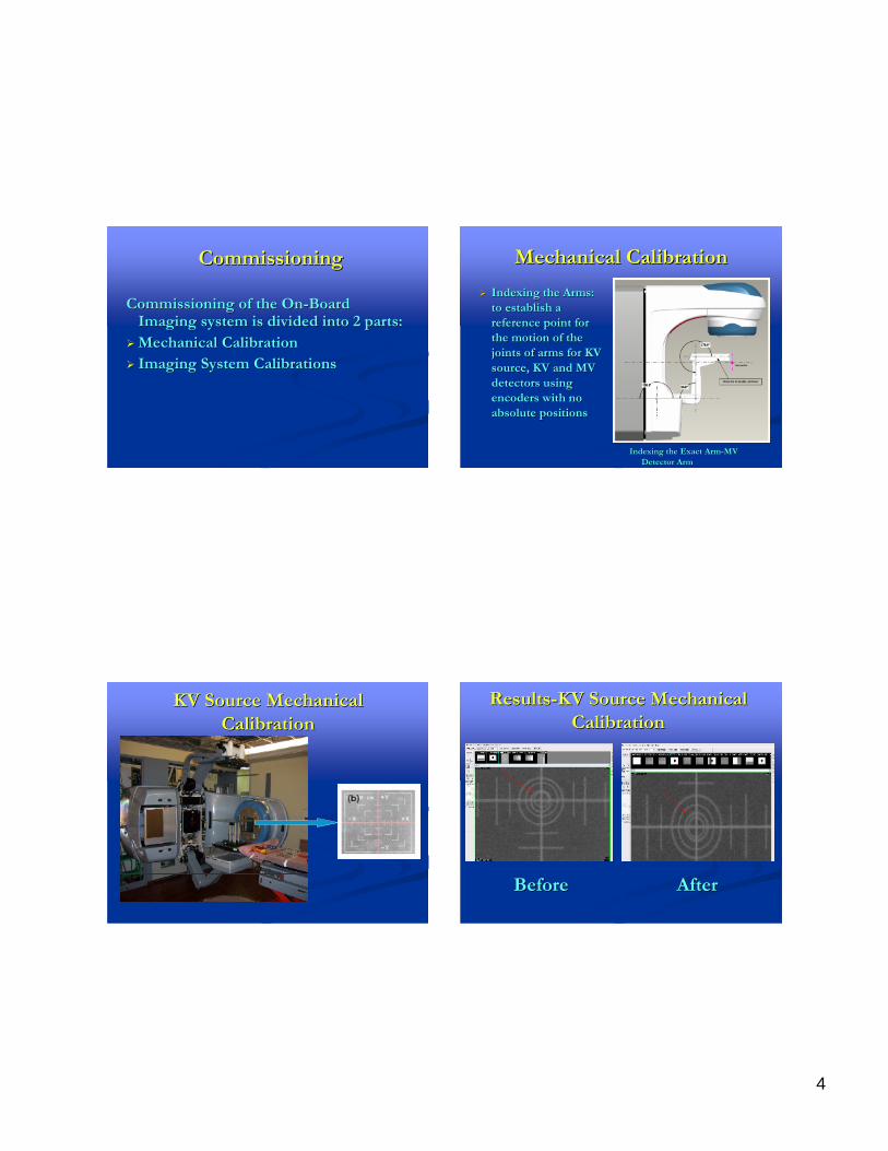
CommissioningCommissioning
Commissioning of the OnCommissioning of the On--Board Board Imaging system is divided into 2 parts:Imaging system is divided into 2 parts:
�� Mechanical CalibrationMechanical Calibration�� Imaging System CalibrationsImaging System Calibrations
Mechanical CalibrationMechanical Calibration�� Indexing the Arms: Indexing the Arms:
to establish a to establish a reference point for reference point for the motion of the the motion of the joints of arms for KV joints of arms for KV source, KV and MV source, KV and MV detectors using detectors using encoders with no encoders with no absolute positionsabsolute positions
Indexing the Exact ArmIndexing the Exact Arm--MV MV Detector ArmDetector Arm
KV Source Mechanical KV Source Mechanical CalibrationCalibration
ResultsResults--KV Source Mechanical KV Source Mechanical CalibrationCalibration
Before Before AfterAfter
5
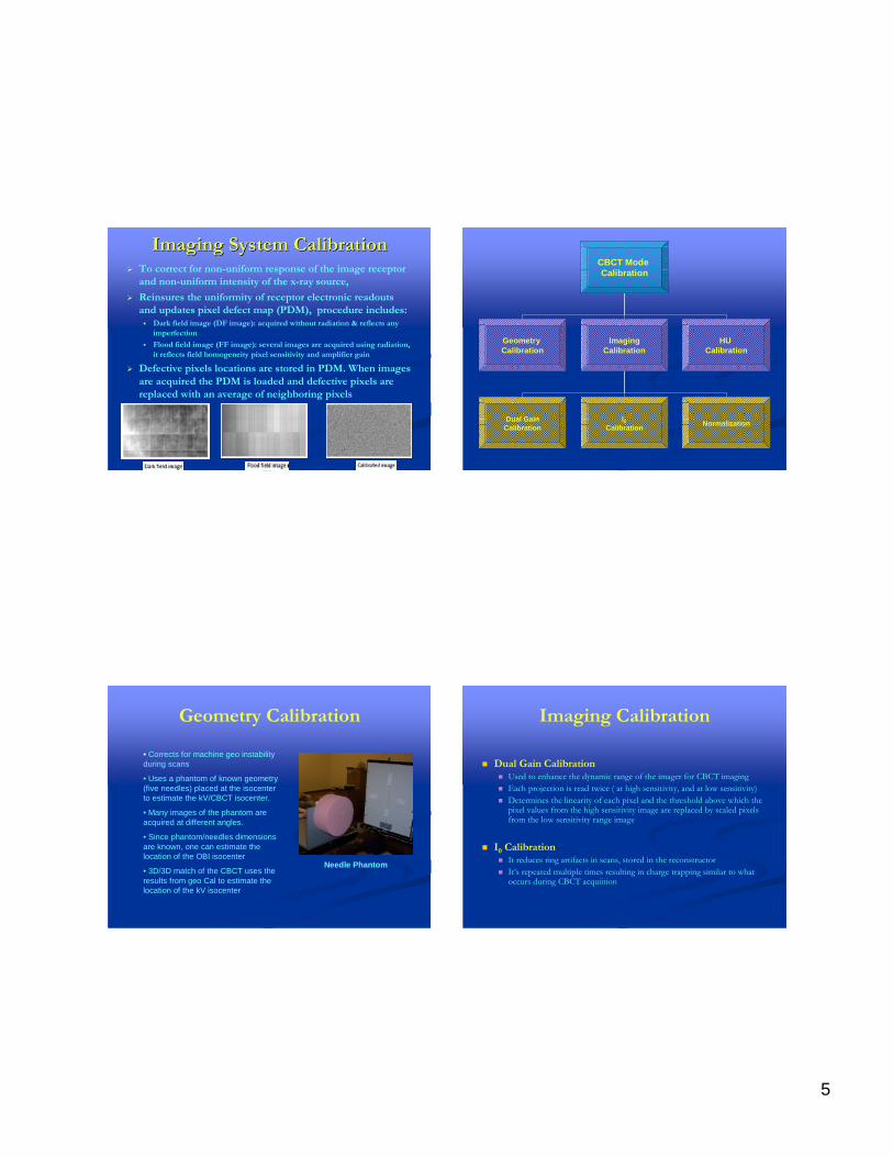
Imaging System CalibrationImaging System Calibration� To correct for non-uniform response of the image receptor
and non-uniform intensity of the x-ray source,� Reinsures the uniformity of receptor electronic readouts
and updates pixel defect map (PDM), procedure includes:� Dark field image (DF image): acquired without radiation & reflects any
imperfection� Flood field image (FF image): several images are acquired using radiation,
it reflects field homogeneity pixel sensitivity and amplifier gain
� Defective pixels locations are stored in PDM. When images are acquired the PDM is loaded and defective pixels are replaced with an average of neighboring pixels
CBCT Mode Calibration
Geometry Calibration
ImagingCalibration
HU Calibration
Dual GainCalibration
I0 Calibration
Normalization
Geometry Calibration
• Corrects for machine geo instability during scans
• Uses a phantom of known geometry (five needles) placed at the isocenterto estimate the kV/CBCT isocenter.
• Many images of the phantom are acquired at different angles.
• Since phantom/needles dimensions are known, one can estimate the location of the OBI isocenter
• 3D/3D match of the CBCT uses the results from geo Cal to estimate the location of the kV isocenter
Needle Phantom
Imaging Calibration
� Dual Gain Calibration� Used to enhance the dynamic range of the imager for CBCT imaging� Each projection is read twice ( at high sensitivity, and at low sensitivity)� Determines the linearity of each pixel and the threshold above which the
pixel values from the high sensitivity image are replaced by scaled pixels from the low sensitivity range image
� I0 Calibration� It reduces ring artifacts in scans, stored in the reconstructor� It’s repeated multiple times resulting in charge trapping similar to what
occurs during CBCT acquiition

6
HU Calibration� Uses Catphan Phantom� Calibrate HU for pixels
in the reconstructed image based for known inserts
Beam Hardening Correction:
• Corrects for increase in energy as x-rays passes through the patient
• Due to the polychromatic nature of the X-rays, lower energy components are attenuated as goes through the patient
• Will increase the effective x-ray energy which causes inconsistency in the reconstruction that assumes constant energy
Daily Daily/Weekly Monthly or Quarterly
Quality Assurance Program
Safety and Functionality Check
� To check that the safety features are functioning properly and that the entire system is ready for clinical operations
Geometry Check� To verify that the KV source and KV detector have
maintained their geometric accuracy and stability

7
weekly geometric QAweekly geometric QA Image QualityImage Quality� To monitor the quality of
radiographic and CBCT images over time
� Not comparable to conventional CT scanners
� QA tests adopted from diagnostic CT scanners using Catphan 504 phantom
� Based on establishing a baseline value
Image Quality
� Tests include:a) Low contrast resolutionb) Spatial resolutionc) HU accuracy d) HU uniformity
Some References for OBI QA…
� S. Yoo, G. Y. Kim, R. Hammoud, E. Elder, T. Pawlicki, H. Guan, T. Fox, G. Luxton, F. F. Yin and P. Munro, Med Phys 33 (11), 4431-4447 (2006)
� J. P. Bissonnette, D. Moseley, E. White, M. Sharpe, T. Purdie and D. A. Jaffray, Int J RadiatOncol Biol Phys 71 (1 Suppl), S57-61 (2008)
� J. P. Bissonnette, D. J. Moseley and D. A. Jaffray, Med Phys 35 (5), 1807-1815 (2008)
8
Patient Dose from CBCT� System Dependent
� kV/ mA� Number of projections� kV system properties (bow-tie)� kV system field size
� Patient Dependent� Size/shape of patient � Body part
� What is our interest?� risk/ benefit ratio needs to be considered
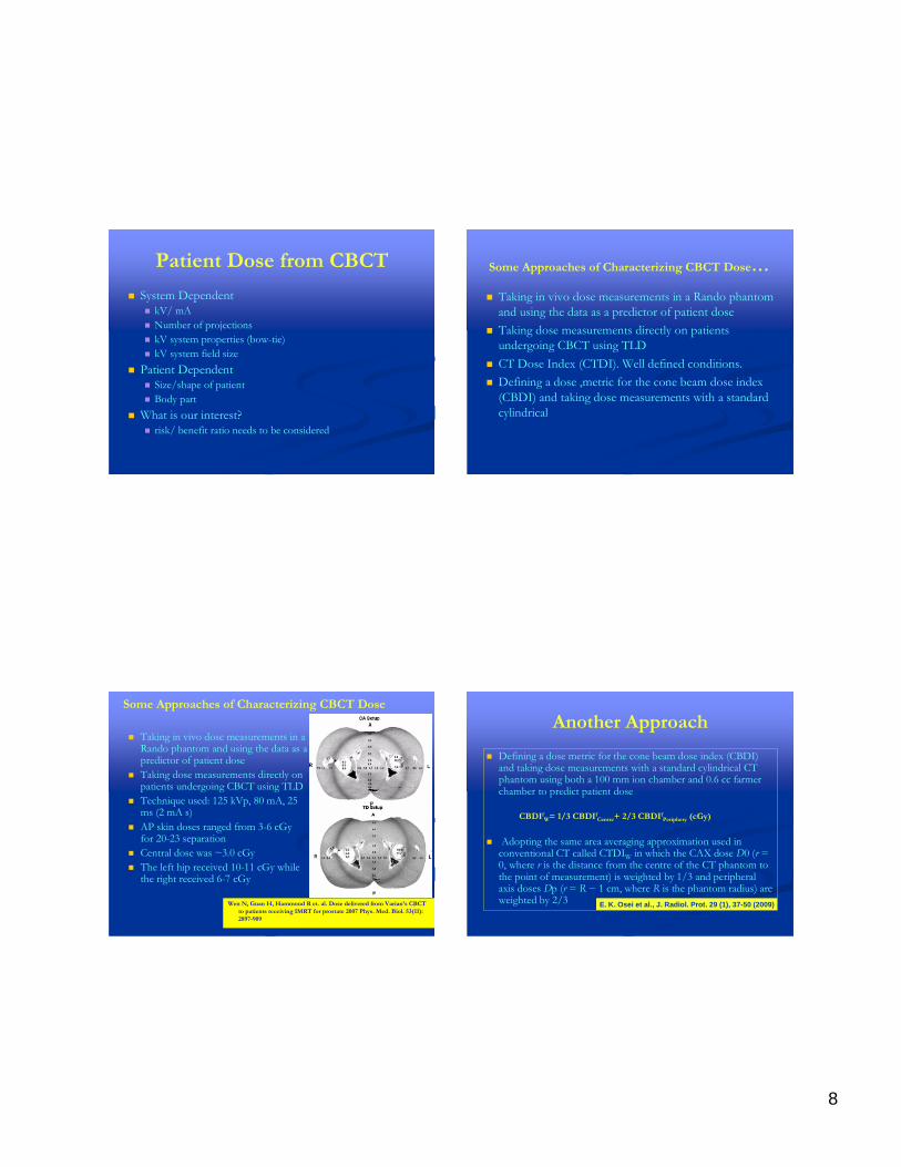
Some Approaches of Characterizing CBCT Dose…� Taking in vivo dose measurements in a Rando phantom
and using the data as a predictor of patient dose� Taking dose measurements directly on patients
undergoing CBCT using TLD� CT Dose Index (CTDI). Well defined conditions.� Defining a dose ,metric for the cone beam dose index
(CBDI) and taking dose measurements with a standard cylindrical
� Taking in vivo dose measurements in a Rando phantom and using the data as a predictor of patient dose
� Taking dose measurements directly on patients undergoing CBCT using TLD
� Technique used: 125 kVp, 80 mA, 25 ms (2 mA s)
� AP skin doses ranged from 3-6 cGyfor 20-23 separation
� Central dose was ~3.0 cGy� The left hip received 10-11 cGy while
the right received 6-7 cGy
Wen N, Guan H, Hammoud R et. al. Dose delivered from Varian’s CBCT to patients receiving IMRT for prostate 2007 Phys. Med. Biol. 53(11): 2897-909
Some Approaches of Characterizing CBCT Dose
� Defining a dose metric for the cone beam dose index (CBDI) and taking dose measurements with a standard cylindrical CT phantom using both a 100 mm ion chamber and 0.6 cc farmer chamber to predict patient dose
CBDIfW= 1/3 CBDIf
Centre+ 2/3 CBDIfPeriphery (cGy)
� Adopting the same area averaging approximation used in conventional CT called CTDIW in which the CAX dose D0 (r = 0, where r is the distance from the centre of the CT phantom to the point of measurement) is weighted by 1/3 and peripheral axis doses Dp (r = R − 1 cm, where R is the phantom radius) are weighted by 2/3 E. K. Osei et al., J. Radiol. Prot. 29 (1), 37-50 (2009)
Another Approach

9
0.460.980.781.44CBDIfPeriphery
(cGy/ 100 mAs)
0.310.440.721.15CBDIfCentre
(cGy/ 100 mAs)
32 cm phantom40 mA, 25 ms (1 mA s)
16 cm phantom40 mA, 25 ms (1 mA s)
2.655.184.938.72CBDIfw
(cGy)
0.410.800.761.34CBDIfw
(cGy/ 100 mAs)
2.976.345.069.34CBDIfPeriphery
(cGy)
2.012.854.657.47CBDIfCentre
(cGy)
Half Fanwith
Bowtie
Half FanNo
Bowtie
Full Fanwith
Bowtie
Full FanNo
Bowtie
• Amer et al.2007, reported 0.38 cGy/ 100 mAs for the Elekta Synergy System using 32 cm diameter phantom
• Song et al. 2008, reported 0.43 cGy/ 100 mAs using 30 cm diameter phantom
CBCT Dose-OBI Advanced Imaging
AAPM TG for Imaging Dose
� Murphy, M.J., et al., The management of imaging dose during image-guided radiotherapy: report of the AAPM Task Group 75. Med Phys, 2007. 34(10): p. 4041-63. Two assumptions are made in the
current MLC bases IMRT process
1. Geometric sizes, shapes, and locations of the targets and organs are the same at the time of planning CT pCT
2. Delivered fluence maps are the same as the planned ones

10
This can trigger a replanfor specific patients when warranted by significant changes
No image Guidance
Bony/Soft Tissue
Summary
Commissioning of kV CBCT systems involves the characterization of the alignment of the kV CBCT system components with the linear accelerator isocentre
Commissioning work then typically focuses on establishing baseline values for image quality. Parameters assessed include spatial linearity (i.e., distance and scale), image uniformity, high and low contrast spatial resolution, and accuracy of CT numbers
Finally, commissioning work involves characterization of the radiation dose to be used for IGRT. The literature reports point dose measurements involving Farmer chambers inserted in cylindrical water or acrylic phantoms

11
Recently, a parameter analogous to the commonly accepted CTDI has been adapted for the kV CBCT geometry, leading to the introduction of CBDI
Though dose delivered from CBCT is small compared to the treatment dose, according to ICRP-60, the dose delivered to patients in medical imaging should be justified and optimized
Justification is positional and target localization which mayallow for dose escalation and potentially higher rates of tumor control and lower rates of complications
Thank YouThank You


![09.[슬라이드]cbct v20160224](https://img.pdfslide.net/doc/110x75/587e18fb1a28abbc2e8b5b83/09cbct-v20160224.jpg)