Embed Size (px)
Citation preview

2D Mass-spring-like Model for Prediction of aSponge’s Behaviour upon Robotic Interaction
Veronica E. Arriola-Rios and Jeremy Wyatt
Abstract Deformable objects abound in nature, and future robots must be able topredict how they are going to behave in order to control them. In this paper wepresent a method capable of learning to predict the behaviour of deformable objects.We use a mass-spring-like model, which we extended to better suit our purposes, andapply it to the concrete scenario of robotic manipulation of an elastic deformableobject. We describe a procedure for automatically calibrating the parameters forthe model taking images and forces from a real sponge as ground truth. We usethis ground truth to provide error measures that drive an evolutionary process thatsearches the parameter space of the model. The resulting calibrated model can makegood predictions for 200 frames (6.667 seconds of real time video) even when testedwith forces being applied in different positions to those trained.
1 Introduction
The objective of this research is the study of the process of physical modelling, pre-diction and evaluation of the predictive capabilities of a mass-spring-like model (asa prerequisite for planning), applied to the concrete scenario of robotic manipulationof an elastic deformable object (dish washing sponge). The robot identifies a regionof the world, where its force sensor detects opposition to movement, and whoseshape and behaviour can be modelled. This region can be better observed though acolour camera. A simple colour segmentation algorithm allows for the identificationand tracking of the region’s behaviour. A regular triangular mesh has been chosen as
Veronica E. Arriola-RiosUniversity of Birmingham, Edgbaston, Birmingham, B15 2TT, U.K. e-mail: [email protected]
Jeremy WyattUniversity of Birmingham, Edgbaston, Birmingham, B15 2TT, U.K. e-mail: [email protected]

Veronica E. Arriola-Rios and Jeremy Wyatt
the form of representation of this region, so that the mass-spring-like model can beapplied to it. A search for the best set of parameters for the model is conducted byevaluating the similarity of the behaviour of the modelled sponge vs. the real spongein the 2D sequence of images. The generalisability of the resulting set is tested ondata gathered when the forces were applied on other parts of the sponge.
The aim of the robot is to find a way to calibrate a model, so that it can describethe behaviour of an occupied physical region (sponge), just with the help of theinformation it can receive from its sensors (a camera and a force sensor) during afew interactions with it (pushing it against an obstacle), and a set of basic knowledgeof how to learn to calibrate those models (search algorithms). From here, the set ofrequirements for the representation of the deformable object are explained in Sect. 3.
For the simulation, we opted for what seemed to be a simple general physicsbased model proposed by Teschner[22]. However, in order to better reproduce theobserved behaviours, some modifications and extensions where introduced, like anew force term that tends to preserve the angles between the springs in the mesh, asit is explained in Sect. 4.
Finally, Sect 5 presents the set of experiments where a Katana arm [14], equippedwith a rigid finger, pushed a sponge against an obstacle (a pencil, fixed and perpen-dicular to the plane of the sponge). See Fig. 1. Given a good set of parameters, theprogram can take as inputs the position of the obstacles for every frame (finger andpencil), the initial position and shape of the sponge, and the sensed force in the di-rection of movement for every frame, and it will be able to predict the deformationof the sponge for the remaining frames in the video (200 frames, 6.667 seconds)with very good accuracy. Such good sets can be found though a systematic searchof the space of parameters or by a simple genetic algorithm. Sect 6 summarises ourconclusions.
2 Related Work
It is hard to catalogue the literature about deformable objects, because it covers awide range of aspects which can be combined to obtain good simulations for dif-ferent situations (we need to start as general as possible, but without loosing theother ones from sight), starting with computer vision (which covers: identification,representation [17, 15], classification, tracking [9]), simulation and manipulation(with applications mainly in robotics, medicine [12], computer graphics [16, 7] andindustry [19]). Sometimes the technique involves manually characterising the be-haviour of a family of materials [18], sometimes the main focus is in topologicalinformation [20], sometimes they overlap across fields or get combined for new ap-plications, like the work by Luo and Nelson [10] where visual tracking can providehaptic information, after a calibration phase of a FEM model links vision and hapticfeedback. The first aim of Computer Graphics is to provide with rich, general andflexible representations of deformable objects: meshes and splines cover these re-quirements in different ways [21], different behaviours can be attained by applying

2D Mass-spring-like Model for Prediction
Fig. 1 Experimental setup. Viewing from a side, a one fingered Katana arm with a force sensorpushes a sponge. The transparent finger pushes the sponge away from it. On the other end, a pencilis used as an obstacle always opposed to the finger. A camera observes and records the action fromthe top.
transformations to vertices and control points, respectively, or by calculating its newpossition individually, as it is done in this work.
Physics based models are commonly used either to reinforce tracking or to pro-duce simulations. Two families of them pervade the scientific literature for de-formable objects [4]:
Finite Element Methods (FEM): Objects are divided into unitary surface or vol-umetric elements joined at discrete node points where a continuous equilibriumequation is approximated over each element. To solve the system, large matricesconnecting the elements must be solved. There are several variations of these:Non-linear FEM, Geometric Nonlinear FEM and Boundary Element Methods(which transforms the equations so that they have to be integrated at the borderof the object instead of the whole volume). The Long Elements Method usesthree mutually perpendicular reference planes that cross the object, and the rel-ative positions of points inside the object with respect to these reference planesare simulated [1].
Mass-spring Methods: Objects are represented by meshes where masses are lo-cated at the nodes and the edges correspond to springs connecting them. It ispossible to discretise and integrate the system of equations for each mass pointseparately, making the process easy and parallelisable. It can be easily applied tomodel volumes or 2D textiles [6].
In the area of predictive tracking, the work by Malassiotis [11] resembles thestructure of our approach (even though the underlying model is different): a trian-gular mesh is calculated to cover the 2-D image of a textured deformable object of

Veronica E. Arriola-Rios and Jeremy Wyatt
interest. The aim of his technique is to identify the principal deformation modes inthe mesh over the observed object, so that future deformations can be expressed ascombinations of these modes. The 2-D shape of the object is modelled with an elas-tic membrane deformed by virtual forces, its strain energy is calculated by makinguse of the finite element theory, which causes it to be costly in time and complexity.This information will guide the deformations of the mesh, while trying to predicthow the object will be deformed. However, the shapes it can describe are limited bywhat can be represented as combinations of the selected modes.
Among the most innovative works with mass-spring methods are: Burion etal. [3], who use a mass-spring skeleton model [4], where filling spheres are placedalong the medial skeleton of the object and are connected together with elastic links,which model elongation, flexion and torsion properties. They use a particle filter al-gorithm to estimate the stiffness coefficients. Since we plan to extend our work toplasticine, the requirement of a skeleton make this approach unsuitable for our pur-poses.
Nevertheless, we chose to work with Teschner’s model [22], following the expe-rience of Morris [13] (in computer graphics), because it addresses the same issuesbut is easily implemented in 2D (the dimensionality of our ground truth). Here, ad-ditionally to the traditional damped springs at the edges, two new energy terms aredevised to enforce preservation of area and volume, making this model more ade-quate to simulate a broad range of realistic behaviours. Also, the terms for distance,area and volume preservation have the same structure, this makes the model uni-form and straightforward to implement and extend. Particularly, we added a termto consider preservation of angles, which considerably improved the stability of thesimulation.
Also Barbara Frank works with learning of deformable objects, in colaborationwith Teschner. Their work has the same general structure than ours, but they usea 3D FEM model for the simulation and search for calibration parameters using agradent descent algorithm[5].
3 Representation of the Deformable Object
It is clear that it took centuries for humans to discover the molecular and atomicstructure of matter, some time more to understand its interactions, how to control thecreation of particular structures, and how the macroscopic attributes emerge fromthe underlying microscopic composition of the material [8]. Nevertheless, there wasan intelligent process that allowed humans to handle materials even before they hadthis knowledge. Since in this work we are interested in the programming of cognitiverobots, the model to be used does not have to be physically correct, but its behaviourmust correspond with the observations, and it must be possible to apply it easily toa wide range of materials and shapes.
There is a set of simple requirements, given by the predictive task we have inmind:
2D Mass-spring-like Model for Prediction
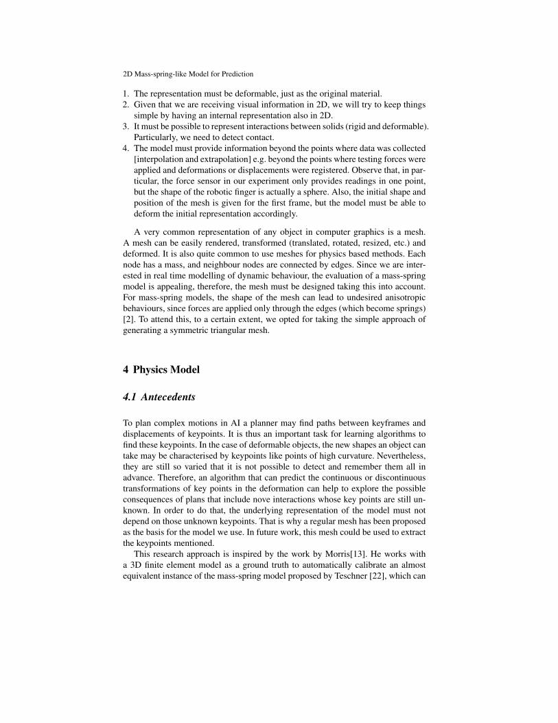
1. The representation must be deformable, just as the original material.2. Given that we are receiving visual information in 2D, we will try to keep things
simple by having an internal representation also in 2D.3. It must be possible to represent interactions between solids (rigid and deformable).
Particularly, we need to detect contact.4. The model must provide information beyond the points where data was collected
[interpolation and extrapolation] e.g. beyond the points where testing forces wereapplied and deformations or displacements were registered. Observe that, in par-ticular, the force sensor in our experiment only provides readings in one point,but the shape of the robotic finger is actually a sphere. Also, the initial shape andposition of the mesh is given for the first frame, but the model must be able todeform the initial representation accordingly.
A very common representation of any object in computer graphics is a mesh.A mesh can be easily rendered, transformed (translated, rotated, resized, etc.) anddeformed. It is also quite common to use meshes for physics based methods. Eachnode has a mass, and neighbour nodes are connected by edges. Since we are inter-ested in real time modelling of dynamic behaviour, the evaluation of a mass-springmodel is appealing, therefore, the mesh must be designed taking this into account.For mass-spring models, the shape of the mesh can lead to undesired anisotropicbehaviours, since forces are applied only through the edges (which become springs)[2]. To attend this, to a certain extent, we opted for taking the simple approach ofgenerating a symmetric triangular mesh.
4 Physics Model
4.1 Antecedents
To plan complex motions in AI a planner may find paths between keyframes anddisplacements of keypoints. It is thus an important task for learning algorithms tofind these keypoints. In the case of deformable objects, the new shapes an object cantake may be characterised by keypoints like points of high curvature. Nevertheless,they are still so varied that it is not possible to detect and remember them all inadvance. Therefore, an algorithm that can predict the continuous or discontinuoustransformations of key points in the deformation can help to explore the possibleconsequences of plans that include nove interactions whose key points are still un-known. In order to do that, the underlying representation of the model must notdepend on those unknown keypoints. That is why a regular mesh has been proposedas the basis for the model we use. In future work, this mesh could be used to extractthe keypoints mentioned.
This research approach is inspired by the work by Morris[13]. He works witha 3D finite element model as a ground truth to automatically calibrate an almostequivalent instance of the mass-spring model proposed by Teschner [22], which can

Veronica E. Arriola-Rios and Jeremy Wyatt
be used instead for real time simulations. Random sets of parameters are proposedand evaluated at equilibrium positions, an adaptive simulated annealing search isused to modify the best parameters of the springs and look for better candidates.Observe that only the final equilibrium positions are evaluated, the forces are appliedon vertices of the mesh and the position of the objects is fixed.
4.2 Inputs
The katana arm has been equipped with a 6 degrees sensor (forces and torques),but for the experiments in this research only one direction is relevant. A colourcamera with a resolution of 800x600 pixels is placed perpendicular to the directionof movement so that it can capture the movement of the finger and the deformationof the sponge. See Fig. 2.
Fig. 2 Viewing from the top, a one fingered Katana arm with a force sensor pushes a sponge. Thetransparent finger pushes the sponge downwards. On the other end (below), a pencil (cap) is usedas an obstacle always opposed to the finger. Both obstacles are represented by thin circles in thephoto.
4.3 Graphical Constraints
Given that the main focus of this work is on the deformable object, the treatmentof the rigid objects involved has been simplified as much as possible. Both, thefinger and the pencil are represented as instances of hard circular obstacles. Thisimplies that any element of the deformable mesh will not be allowed to enter orcross over the enclosed region. This constraint is enforced at every frame duringthe simulation through a standard set of collision detection subroutines. Also the
2D Mass-spring-like Model for Prediction
triangulation must remain without crossings. Whenever the displacemente of a nodeproduces a crossing, the opposite ending of the affected triangle and the node itselfget pushed in opposite directions to undo the error. If a set of parameters can notrespect this constraints it is eliminated.
4.4 From Energy Constraints to Force terms
The core of the model is in the energy terms that enforce the preservation of threequantities: length of the springs, area of each triangle and the internal angles ofthe triangles. The first two terms are directly derived for the two dimensional casefollowing Teschner’s method and can be seen in [22]. The last term is our originalcontribution.
Equal masses are allocated at the nodes of the mesh and the edges correspond tothe springs. The dynamics of the deformation of the objects are represented throughdynamic constraints from which potential energies are obtained. The dynamics ofthe system are ruled by the forces that minimise these energies. Teschner indicateshow to derive those forces and Morris [13] uses geometrical arguments to explainthem. The following sections indicate the corresponding expressions.
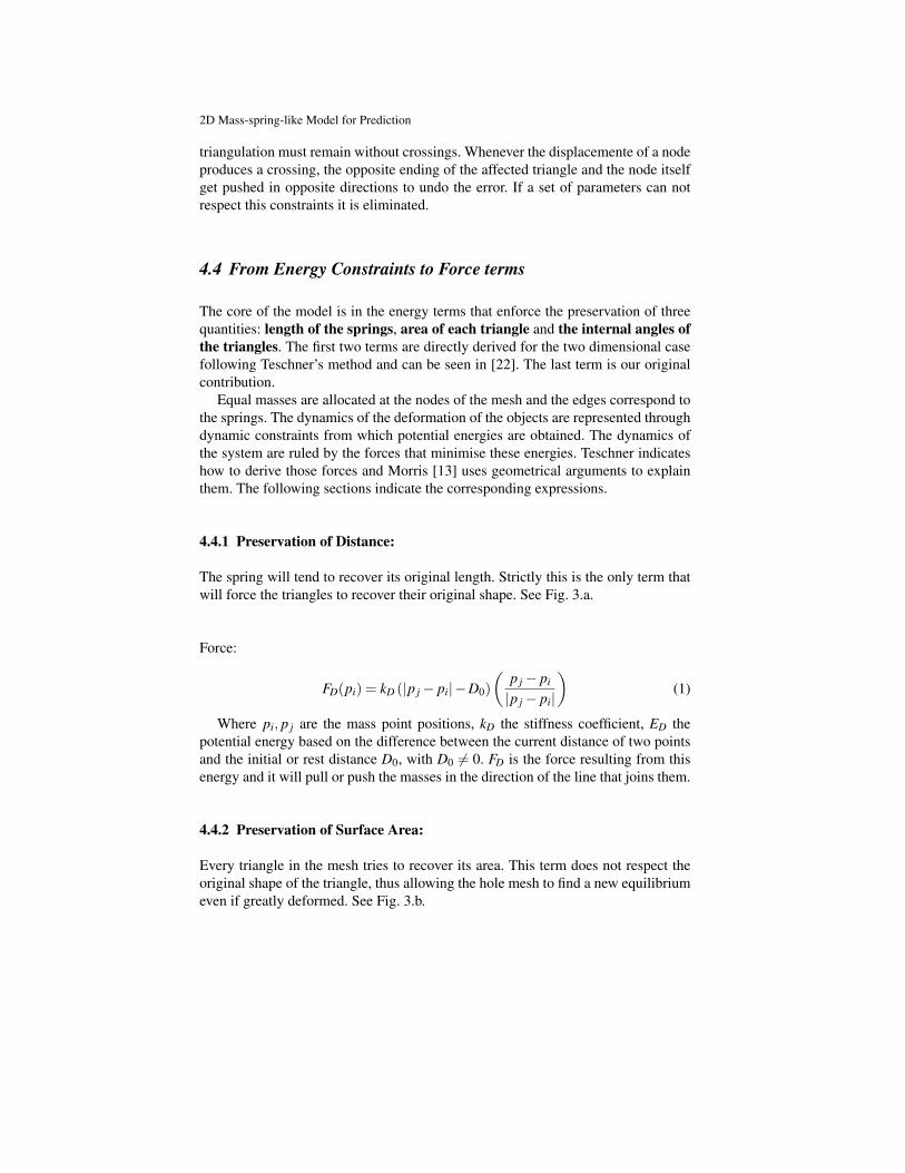
4.4.1 Preservation of Distance:
The spring will tend to recover its original length. Strictly this is the only term thatwill force the triangles to recover their original shape. See Fig. 3.a.
Force:
FD(pi) = kD (|p j− pi|−D0)(
p j− pi
|p j− pi|
)(1)
Where pi, p j are the mass point positions, kD the stiffness coefficient, ED thepotential energy based on the difference between the current distance of two pointsand the initial or rest distance D0, with D0 6= 0. FD is the force resulting from thisenergy and it will pull or push the masses in the direction of the line that joins them.
4.4.2 Preservation of Surface Area:
Every triangle in the mesh tries to recover its area. This term does not respect theoriginal shape of the triangle, thus allowing the hole mesh to find a new equilibriumeven if greatly deformed. See Fig. 3.b.

Veronica E. Arriola-Rios and Jeremy Wyatt
Force:
FA(pi) = kA · f orcemagA(pi) · f orcedirA(pi) (2)
f orcemagA(pi) =12 ((pk− pi)× (p j− pi))−A0
A0
f orcedirA(pi) =FA(pi)|FA(pi)|
=areagradient(pi)|areagradient(pi)|
areagradient(pi) = (pi− p j)−(
(pk− p j) ·(pk− p j) · (pi− p j)(pk− p j) · (pk− p j)
)Where the energy EA considers triples of mass points that build surface triangles.
EA represents energy based on the difference of the current area of a surface triangleand its initial area A0 with A0 6= 0. Here kA is an area stiffness coefficient. Eachmass with move in the direction of the height of the triangle that passes through it,to increase or decrease its area.
Fig. 3 a. The linear force of the spring pulls inside if the spring was elongated, or outside if itwas compressed. b. The triangle tries to quickly recover its area by pulling all its vertices along itscorresponding heights.
4.4.3 Preservation of Angles:
We added an extra term to enforce the preservation of angles. The energy dependson the difference of the angles between adjacent edges. The force emerging fromthis term is harder to visualize, it is a linear combinations of the vectors along theedges that form the angle of interest, it pretends to restore the original angle, butdoes not pay attention to the original size. See Fig. 4. Therefore, it helps recover a

2D Mass-spring-like Model for Prediction
similar triangle, but if used alone can collapse or explode the triangle. An additionalline in the code also forces an inverted angle to recover its original orientation.
Energy:
Eϕ(ϕ) =12
kϕ(ϕ−ϕ0) * (3)
ϕ(pi, p j, pk) = arccos
((p j− pi) · (pk− pi)∥∥p j− pi
∥∥‖pk− pi‖
)2
* It was also considered to multiply Eϕ by the lengths of the edges, but it hasn’timproved the performance of the model.
Where ϕ is the angle between adjacent edges, Eϕ is the energy associated tochanges in the angle and kϕ , the corresponding stiffness constant. Contrary to theprevious cases, it is not so evident in which direction the force will act.
Force:
Fϕ(pi) = kϕ(ϕ−ϕ0)∂ϕ
∂ pi(4)
∂ϕ
∂ pi(pi) =
1
d jidki
√1−[
pp(d ji)(dki)
]2
{[1− pp
d2ki
](pk− pi)+
[1− pp
d2ji
](p j− pi)
}
pp(pi) = (p j− pi) · (pk− pi)d ji(pi) =
∥∥p j− pi∥∥
dki(pi) = ‖pk− pi‖ (5)
The differential equations that rule the behaviour of the system are integratedwith a numerical approach. Originally the acceleration of the masses is proportionalto the force, the equation must be integrated twice to obtain the positions as a func-tion of time. In this case, in order to compute the new state of the system (x(t + h)position at time t + h, v(t + h) velocity at time t + h) the Verlet integration schemeis used [6].
x(t +h) = 2x(t)− x(t−h)+h2 F(t)m
+O(h4) (6)
v(t +h) =x(t +h)− x(t−h)
2h+O(h2) (7)
with F(t) = FD(t)+FA(t)+Fϕ(t), and m, the mass of the node.

Veronica E. Arriola-Rios and Jeremy Wyatt
Fig. 4 The angular force displaces the vertex of interest in the direction of maximum change of theangle in order to recover its original value. This direction is a linear combination of the vectors thatemerge from both edges forming the angle, and does not respect the original size of the triangle.
This will yield the typical oscillatory behaviour of springs. However, to simulatea heavily damped sponge we made the velocities proportional to the forces. Now,instead of having a second order set of equations, the set is first order. The simula-tions we obtained were closer to the observed behaviour. Also, for every frame inthe simulation, there are 10 steps in the numerical integration.
x(t +h) = x(t)+hF(t)m
(8)
with F(t) = FD(t)+FA(t)+Fϕ(t).However, to give stability to the numerical integration process it is necessary
to add damping terms to the linear force. Teschner gives the following formula tocalculate the force:
F i(p0, ..., pn−1,v0, ...,vn−1) =
(−kC− kd ∑
0≤ j<n
∂C∂ p j
v j
)∂C∂ pi
(9)
Given that FD for every pi only depends on pi and p j, the sum has two terms.
FD(pi, p j) =(
kD
(|p j− pi|−D0
D0
)+ kd
1D0
p j− pi
|p j− pi|· (v j− vi)
)1
D0
(p j− pi
|p j− pi|
)(10)
Still these forces only represent the internal tension of the material that makesit tend to recover its shape. The external force applied by the finger and measuredby the sensor is added to the forces acting on the nearest vertex to the finger in themesh. Additionally, the mesh must respect the graphical constraint imposed by thefinger, which greatly helps in shaping the sponge, and propagates the effect causedby the hole circular shape.
At the beginning we assumed that the spring terms would suffice even to repro-duce the slight translation of the sponge as it is pushed by the finger, since pushinga spring should make this push its neighbours and so on. However, our first experi-

2D Mass-spring-like Model for Prediction
ments showed it not to be the case. The effect of pushing a spring get diluted amongthe deformation of the spring and the area and angular terms. In order to obtain thetranslation, we must add a solid propagation of the finger’s force. This is, that part ofthe force is absorbed in deformation, while another amount affects all vertices andproduces an even displacement. For the moment we just added an extra parameterto the model that fixes the amount of force that is invested in translation. There isan additional parameter ft that represents a solid force that is constantly propagatedto the entire sponge (to every vertex) and accounts for the overal solid translation ofthe object.
The algorithms where implemented in C++, making use of the GNU compilergcc 4.4.4. The triangulations where managed with the CGAL library, and the visionpart was handled with OpenCV.
5 Experiments
5.1 Evaluation: Difference of Areas
The function used to automate the decision of what makes a good set of parametersis quite simple, but provides a sufficient criterion to eliminate bad sets of parameters.It consists in measuring the difference between the area occupied by the image ofthe sponge and the area covered by the mesh of the model (this is done pixel bypixel). The bigger this difference, the worst the model. All the differences frame byframe are added up to assign a mark to the set of parameters during the hole durationof the video. See Fig. 5.
Fig. 5 a) Shows the original image with the mesh overlaid as the simulation is executed. b) Thearea occupied by the sponge. c) The area occupied by the mesh. The evaluation function countsthe pixels in the difference: those in the sponge that are not in the mesh, and those in the mesh thatare not in the sponge. The positions are absolute.

Veronica E. Arriola-Rios and Jeremy Wyatt
5.2 Results
The numerical value of the forces measured in the relevant direction of move-ment range from -3.8 N (due to noise in the sensor) to 170.3 N. We use a sim-ple genetic algorithm to find good sets of parameters. Here, the first generation hasonly random values for every parameter, within the ranges: kD ∈ [0.001,1000.0],kd ∈ [0.001,100.0], kA ∈ [0.001,200.0], kϕ ∈ [0.001,700.0] and ft ∈ [0.0,200.0].After, for every generation, one third of the new elements are the best of the previ-ous generation (they don’t get evaluated again), one third are the previous ones plusGaussian noise (the value of sigma gets reduced for every generation from 100 to10), and the last third are new random elements. With the genetic algorithm, afterthe 8th generation the set of parameters with the best mark has been the same. Itproduced the videos summarized in Fig. 6, and the marks for the best sets are sum-marized in Table 1. However, other executions of the same algorithm have foundother good sets of values (any of them would serve the purposes of the robot). Nev-ertheless we completed the analysis with a systematic run.
Fig. 6 Sequence taken from a simulation with the best set as evaluated by a genetic algorithm:kD = 492.184, kd = 33.145, kA = 67.331, kϕ = 1.37 and ft = 20.45. a) Over the video used for theevaluation of the parameters. a) 5. In the last frame an error remains due to the oversimplificationof the translation function: the elements of the sponge keep being pushed down even after thefinger has stopped moving (frame 300). b) Same model and parameters but with the forces actingon different positions. The predictions are fairly correct for 200 frames. We have another set wherethe forces are applied to the right side of the sponge, the results are symmetric, but are not shownfor lack of space.
We noticed that big values for the preservation of areas create severe problemswhile trying to maintain the graphical constraints (T-test t = 8.33, for all the follow-
2D Mass-spring-like Model for Prediction
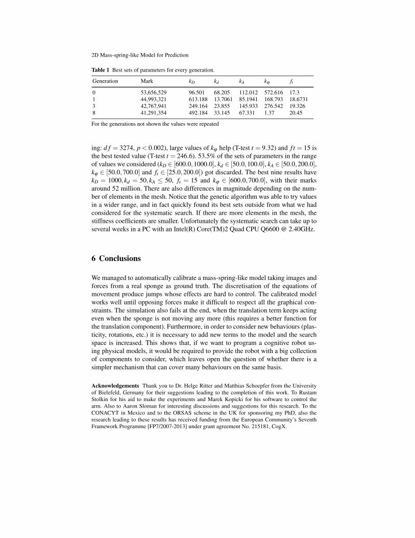
Table 1 Best sets of parameters for every generation.
Generation Mark kD kd kA kϕ ft
0 53,656,529 96.501 68.205 112.012 572.616 17.31 44,993,321 613.188 13.7061 85.1941 168.793 18.67313 42,767,941 249.164 23.855 145.933 276.542 19.3268 41,291,354 492.184 33.145 67.331 1.37 20.45
For the generations not shown the values were repeated
ing: d f = 3274, p < 0.002), large values of kϕ help (T-test t = 9.32) and f t = 15 isthe best tested value (T-test t = 246.6). 53.5% of the sets of parameters in the rangeof values we considered (kD ∈ [600.0,1000.0], kd ∈ [50.0,100.0], kA ∈ [50.0,200.0],kϕ ∈ [50.0,700.0] and ft ∈ [25.0,200.0]) got discarded. The best nine results havekD = 1000,kd = 50,kA ≤ 50, ft = 15 and kϕ ∈ [600.0,700.0], with their marksaround 52 million. There are also differences in magnitude depending on the num-ber of elements in the mesh. Notice that the genetic algorithm was able to try valuesin a wider range, and in fact quickly found its best sets outside from what we hadconsidered for the systematic search. If there are more elements in the mesh, thestiffness coefficients are smaller. Unfortunately the systematic search can take up toseveral weeks in a PC with an Intel(R) Core(TM)2 Quad CPU Q6600 @ 2.40GHz.
6 Conclusions
We managed to automatically calibrate a mass-spring-like model taking images andforces from a real sponge as ground truth. The discretisation of the equations ofmovement produce jumps whose effects are hard to control. The calibrated modelworks well until opposing forces make it difficult to respect all the graphical con-straints. The simulation also fails at the end, when the translation term keeps actingeven when the sponge is not moving any more (this requires a better function forthe translation component). Furthermore, in order to consider new behaviours (plas-ticity, rotations, etc.) it is necessary to add new terms to the model and the searchspace is increased. This shows that, if we want to program a cognitive robot us-ing physical models, it would be required to provide the robot with a big collectionof components to consider, which leaves open the question of whether there is asimpler mechanism that can cover many behaviours on the same basis.
Acknowledgements Thank you to Dr. Helge Ritter and Matthias Schoepfer from the Universityof Bielefeld, Germany for their suggestions leading to the completion of this work. To RustamStolkin for his aid to make the experiments and Marek Kopicki for his software to control thearm. Also to Aaron Sloman for interesting discussions and suggestions for this research. To theCONACYT in Mexico and to the ORSAS scheme in the UK for sponsoring my PhD, also theresearch leading to these results has received funding from the European Community’s SeventhFramework Programme [FP7/2007-2013] under grant agreement No. 215181, CogX.

Veronica E. Arriola-Rios and Jeremy Wyatt
References
1. Balaniuk, R., Salisbury, K.: Dynamic simulation of deformable objects using the long ele-ments method. 10th Symposium On Haptic Interfaces For Virtual Environment And Teleop-erator Systems, Proceedings pp. 58–65 (2002)
2. Bourguignon, D., Cani, M.P.: Controlling anisotropy in mass-spring systems. In:N. Magnenat-Thalmann, D. Thalmann, B. Arnaldi (eds.) 11th Eurographics Workshop onComputer Animation and Simulation, EGCAS 2000, August, 2000, Springer Computer Sci-ence, pp. 113–123. Springer-Verlag, Interlaken, Suisse (2000)
3. Burion, S., Conti, F., Petrovskaya, A., Baur, C., Khatib, O.: Identifying physical properties ofdeformable objects by using particle filters. 2008 Ieee International Conference On RoboticsAnd Automation, Vols 1-9 pp. 1112–1117 (2008)
4. Conti, F., Khatib, O., Baur, C.: Interactive rendering of deformable objects based on a fillingsphere modeling approach. In: Robotics and Automation, 2003. Proceedings. ICRA ’03. IEEEInternational Conference on, vol. 3, pp. 3716 – 3721 (2003)
5. Frank, B., Schmedding, R., Stachniss, C., Teschner, M., Burgard, W.: Learning the elastic-ity parameters of deformable objects with a manipulation robot. In: Proc. of the IEEE/RSJInternational Conference on Intelligent Robots and Systems (IROS) (2010)
6. Fuhrmann, A., Gro, C., Luckas, V.: Interactive animation of cloth including self collisiondetection. Journal of WSCG 11(1), 141–148 (2003)
7. Gibson, S.F.F., Mirtich, B.: A survey of deformable modeling in computer graphics. Tech.rep., MERL (Mitsubishi Electric Research Laboratory) (1997)
8. Gonzlez-Vias, W., Mancini, H.L.: An Introduction To Materials Science. Princeton UniversityPress, U.S.A. (2004). Translation of: Ciencia de los Materiales
9. Kass, M., Witkin, A., Terzopuolos, D.: Snakes: Active contour models. International JournalOf Computer Vision 1(4), 321–331 (1988)
10. Luo, Y.H., Nelson, B.J.: Fusing force and vision feedback for manipulating deformable ob-jects. Journal Of Robotic Systems 18(3), 103–117 (2001)
11. Malassiotis, S., Strintzis, M.G.: Tracking textured deformable objects using a finite-elementmesh. Ieee Transactions On Circuits And Systems For Video Technology 8(6), 756–774(1998)
12. McInerney, T., Terzopoulos, D.: Deformable models in medical image analysis: a survey. MedImage Anal 1(2), 91–108 (1996)
13. Morris, D., Salisbury, K.: Automatic preparation, calibration, and simulation of deformableobjects. Computer Methods In Biomechanics And Biomedical Engineering 11(3), 263–279(2008)
14. Neuronics: Katana user manual and technical description. http://www.neuronics.ch (2004)15. Newcombe, R.A., Davison, A.J.: Live dense reconstruction with a single moving camera. In:
CVPR (2010)16. O’Brien, J.F., Bargteil, A.W., Hodgins, J.K.: Graphical modeling and animation of ductile
fracture. ACM Trans. Graph. 21(3), 291–294 (2002)17. Ravishankar, S., Jain, A., Mittal, A.: Multi-stage contour based detection of deformable ob-
jects. Computer Vision - Eccv 2008, Pt I, Proceedings 5302, 483–496 (2008)18. Remde, A., Abegg, F., Worn, H.: Ein allgemainer ansatz zur montage deformierarbarer lin-
earer objekte mit industrierobotern (a general approach for the assembly of deformable linearobjects with industrial robots). In: Robotik’2000. Berlin, Germany (2000)
19. Saadat, M., Nan, P.: Industrial applications of automatic manipulation of flexible materials.Industrial Robot 29(5), 434–442 (2002)
20. Saha, M., Isto, P.: Manipulation planning for deformable linear objects. Ieee Transactions OnRobotics 23(6), 1141–1150 (2007)
21. Song, Y., Bai, L.: 3d modeling for deformable objects. Articulated Motion And DeformableObjects, Proceedings 5098, 175–187 (2008)
22. Teschner, M., Heidelberg, B., Muller, M., Gross, M.: A versatile and robust model for geo-metrically complex deformable solids. In: Proceedings of Computer Graphics International(CGI’04), pp. 312–319. Crete, Greece (2004)