Embed Size (px)
Citation preview
1336
Journal of Engineering Sciences Assiut University
Faculty of Engineering
Vol. 42
No. 6
November 2014
PP. 1336 – 1348
* Corresponding author.
Email address: [email protected]
2D PLAXIS FINITE ELEMENT MODELING OF ASPHALT-
CONCRETE PAVEMENT REINFORCED WITH GEOGRID
Hamdy Faheem * and Ahmed Mohamed Hassan
Faculty of Eng., Minia University, Civil Engineering Department, Egypt
(Received 30 November 2014; Accepted 30 December 2014)
ABSTRACT
Geogrid-reinforcement is often used in conjunction with unbound base layers to enhance flexible
pavements performance. This paper presents an axisymmetric finite element (FE) model to analyze
the behavior of unreinforced and geogrid reinforced bituminous pavement subjected to static and
dynamic loadings. The model was loaded with an incremental loading and the critical pavement
responses such as effective stress and vertical surface deflection were determined for unreinforced
and geogrid reinforced flexible pavement. The results indicated that during static loading, a
moderate effect on the pavement behavior was observed due to the reinforcing geogrid layer. This
effect was not noted in case of dynamic loading. The effect of dynamic loading frequency on
pavement settlement was significant especially for high loading amplitudes. The results also showed
no significant improvement in pavement system behavior was obtained by adding another layer of
geogrid reinforcement.
Keywords: Geogrid, Pavement Performance, Plaxis Program, FE Analysis; Flexible Pavement;
Reinforced Pavement; Dynamic Loading
1. Introduction
In the last few decades, geosynthetic reinforcement, particularly high modulus
polymeric geogrid, has been increasingly utilized within pavement layers to improve the
structural performance of both newly constructed and rehabilitated flexible pavement.
Besides reducing the rutting strain, geogrids also resist fatigue (horizontal) strain through
the tensioned membrane effect, induced in the bituminous concrete layer [1]. The Geogrid-
reinforcement layer is usually placed between the sub-base and sub grade interface or
between the base course and sub-base. Due to the wide application of this technique, many
experimental and analytical studies have been conducted to assess and potentially quantify
the improvements associated with geogrid base reinforcement of roadways. The use of
geogrid reinforcement in roadway applications started in the 1970s. Since then, the
technique of geogrid reinforcement has been increasingly used and many studies have been
performed to investigate its behavior in roadway applications [2, 3, 4, and 5].
1337
Hamdy Faheem and Ahmed Mohamed Hassan, 2D plaxis finite element modeling of asphalt………
Numerous researchers studied the impact of geosynthetic reinforcement over structural
performance of paved roads through laboratory, field, and numerical modeling methods.
Pandey et al. [6] performed a series of FE simulations to evaluate the benefits of
integrating a high modulus geogrid as reinforcement into the pavement layers. Their study
presents a two dimensional axisymmetric FE model that analyzes the behavior of
unreinforced and geogrid reinforced bituminous pavement subjected to static and dynamic
loading conditions. The results showed that placing geogrid reinforcement at the base-
bituminous concrete interface leads to the highest reduction in fatigue (horizontal) strain.
The highest decrease of vertical strain occurs when the reinforcement is placed at the
interface of base and sub grade layers. Barksdale, Brown and Chan [7] compared the
structural performance of unreinforced and geogrid reinforced pavement subjected on
cyclic loading condition through laboratory experimentation. Performance characterization
of the unreinforced and geogrid reinforced pavement was carried out on the basis vertical
permanent deformation. The results of the study indicated that for a stronger pavement, the
stiff geogrid at the bottom of the granular base did not produce any significant
improvement. Their results further indicated that placing the geogrid in the middle and
bottom of the base layers, despite its lower stiffness, resulted in better performance against
permanent deformation than the use of a geotextile. Numerical simulation carried out by
them using FE analysis techniques showed that the benefits of geosynthetic reinforcements
are more pronounced for weaker subgrades. Virgile et al. [8] studied the flexural behavior
of bi-layer bituminous system reinforced with geogrid through laboratory experiments.
Geogrid was placed at the interface of bituminous layer. The laboratory study showed that
the reinforced system improved the resistance to repeated load cycles by 66% to 100 %
and delayed the inversion from decreasing to increasing rate of the permanent deformation
evolution curve. However, this study did not include the effect of geogrids on fatigue
resistance of asphalt layers. Dondi [9] used the FE program ABAQUS to model a
geosynthetic reinforced flexible pavement. Three dimensional static analysis was carried
out using linear and nonlinear constitutive material models. Bituminous concrete layer and
geosynthetic reinforcement were modeled using a linear elastic material model based on
Hook’s law while Drucker-Prager and Cam Clay material models were used to model base
course and subgrade layers. The results of their study indicated 15-20% reduction in
vertical displacement under the load in reinforced section and 2-2.5 times increase in
fatigue life of reinforced sections compared to unreinforced sections. Moayedi et al. [10]
studied the effect of geogrid reinforcement location in paved road improvement using
axisymmetric pavement response model developed through the FE program PLAXIS.
Bituminous concrete layer and geogrid were modeled as a linear elastic isotropic material
while the Moho-Coulomb material model was used to simulate granular layers. Pavement
responses were determined under static loading condition. They showed that the
geosynthetic reinforcement placed at the bottom of bituminous concrete layer leads to the
highest reduction in vertical pavement deflection. Miura et al. [11] performed a FE
analysis on reinforced and unreinforced pavement sections. They compared the results of
the FE analysis with the experimental measurements on similar sections. The results
indicated that the prediction of FE analysis was not in agreement with the behavior
observed in the tests. The predicted reduction in surface displacements was 5% compared
to an actual displacement reduction of 35% measured by the tests. Dondi [9] used
ABAQUS software package to conduct a three dimensional FE analysis to model the
geosynthetic reinforced pavements. The results of this study indicated that the use of the
1338
JES, Assiut University, Faculty of Engineering, Vol. 42, No. 6, November 2014, pp. 1336 – 1348
reinforcement resulted in an improvement in the bearing capacity of the subgrade layer and
a reduction in the shear stresses and strains on top of it. In addition, the vertical
displacement was also reduced by 15 to 20 % due to the intrusion of geosynthetic
reinforcement. Wathugala et al. [12] used ABAQUS FE software package to formulate the
FE model for pavements with geogrid reinforced bases. The results of the analysis were
compared with an unreinforced pavement sections at the same geometry and material
properties. The comparisons indicated that the inclusion of geogrid reinforcement reduced
the permanent deformations by 20% for a single load cycle. This level of improvement was
related to the flexural rigidity of the geosynthetics caused by the model presentation used
by the authors [3]. Leng and Gabr [13] conducted a numerical analysis using ABAQUS to
investigate the performance of reinforced unpaved pavement sections. They reported that
the performance of the reinforced section was enhanced as the modulus ratio of the
aggregate layer to the subgrade decreased. The critical pavement responses were
significantly reduced for higher modulus geogrid or better soil/aggregate-geogrid interface
property. Nazzal et al. [14] developed a finite-element model with ABAQUS software
package to investigate the effect of placing geosynthetic reinforcement within the base
course layer on the response of a flexible pavement structure. Finite-element analyses were
conducted on different unreinforced and geosynthetic reinforced flexible pavement
sections. The results of the FE analyses showed that the geosynthetic reinforcement
reduced the lateral strains within the base course and subgrade layers. Furthermore, the
inclusion of the geosynthetic layer resulted in a significant reduction in the vertical and
shear strains at the top of the subgrade layer. The improvement of the geosynthetic layer
was found to be more pronounced in the development of the plastic strains rather than the
resilient strains. The reinforcement benefits were enhanced as its elastic modulus increased.
Many researchers believe that geogrid should be placed at the top of base course while
others have found that geogrid should be placed at the base–subgrade interface. In the
present study a FE simulation of an asphalt-concrete typical pavement section reinforced
with geogrid was carried out using 2D Plaxis FE program. The model was loaded with an
axle load of increasing from 50 kPa to 600 kPa. Effect of a geogrid layer placed under the
pavement layer was investigated under static and dynamic load.
2. Development of the numerical model
A typical reinforced pavement system consists of hot-mix asphalt layer, base course layer,
sub-base layer and subgrade layer as well as reinforcement layers. The pavement is modeled
as a multilayer structure subjected to static and dynamic loading. The model was developed
using 2-D Plaxis FE software to analyze the unreinforced and geogrid reinforced flexible
pavement structure [15]. The load is applied as uniform pressure acting on a circular area of
radius 0.2 m. Applied pressure values were: 50, 100, 200, 300, 400, 500, and 600 kPa. Linear
elastic materials were assigned to the AC and the geogrid layers whereas the base course and
the sub-base layers were modeled using Mohr-coulomb constitutive model.
An axisymmetric model was utilized in the analysis using 15-noded structural solid
element with medium refinement. Axisymmetric modeling was chosen in this study
because it could simulate circular loading and did not require excessive computational time
under dynamic loading [2, 16].
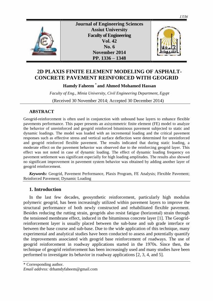
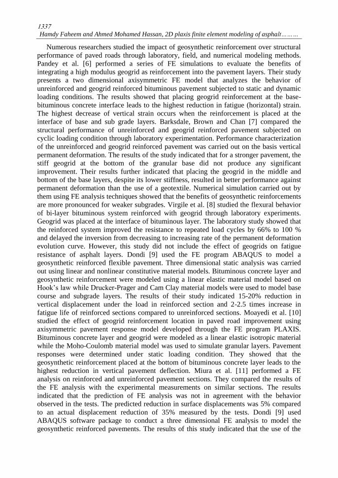
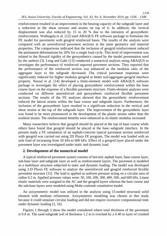
Figures 1 through 3 show the model considered where total thickness of the pavement
is 0.8 m. The sand subgrade soil of thickness 1.2 m is overlaid by a 0.40 m layer of crushed
1339
Hamdy Faheem and Ahmed Mohamed Hassan, 2D plaxis finite element modeling of asphalt………
gravel as sub-base, 0.30 m crushed gravel as base course and 0.1 m asphalt concrete on
top. The bottom of model was fixed in both vertical and horizontal directions. Both edges
of the models were restricted against horizontal movement. Material parameters and
constitutive models used are shown in Table (1) whereas Table (2) shows mechanical
properties of geogrid reinforcement.
Fig. 1. FE axisymmetric model for unreinforced pavement.
Fig. 2. FE axisymmetric model considered for one-layer reinforced pavement.
Fig. 3. FE axisymmetric model considered for two-layer reinforced pavement.
1340
JES, Assiut University, Faculty of Engineering, Vol. 42, No. 6, November 2014, pp. 1336 – 1348
Table 1. Material properties
Material
Asphalt
Concrete
Base
(Crushed
Stone)
Sub-base
(Crushed
Stone)
Sub-
grade
Sand) )
Model
Thickness (m)
Young’s modulus ( KPa)
Poisson’s Ratio
Dry density (kN/m3)
Saturated density
(kN/m3)
Cohesion (kN/m2)
Friction angle (degree)
Dilatation angle (degree)
kx[m/day]
ky[m/day]
Linear-
elastic
0.10
2100×103
0.45
20.0
-
-
-
-
-
-
Mohr-
Coulomb
0.30
100×103
0.35
20.0
22.00
30
43
13
1.000
1.000
Mohr-
Coulomb
0.40
50×103
0.30
18.0
20.0
20
40
14
1.000
1.000
Mohr-
Coulomb
1.20
20×103
0.30
17.0
18.0
0
35
5
1.000
1.000
Table 2. Mechanical properties of geogrid reinforcement
Material Elastic axial stiffness (KN/m) Poisson’ ratio
Geogrid 1 213 0.25
Geogrid 2 534 0.25
Geogrid 3 950 0.25
3. Results and analysis
3.1 Static loading
3.1.1 One layer of geogrid In this section static loading condition is presented for both unreinforced and geogrid-
reinforced base. Applied pressure ranged from 50 kPa to 600 kPa and geogrid was placed
at the interface of asphalt concrete layer and base course. Critical pavement responses i.e.
effective stress and total vertical displacement of unreinforced and geogrid reinforced
pavements are determined under for each static loading value.
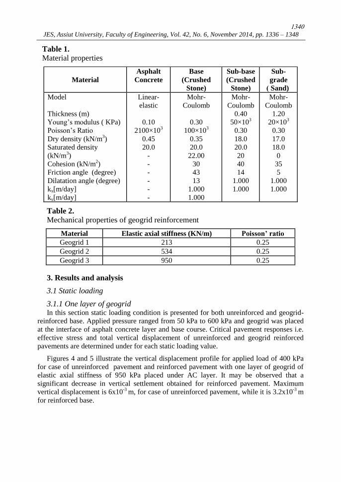
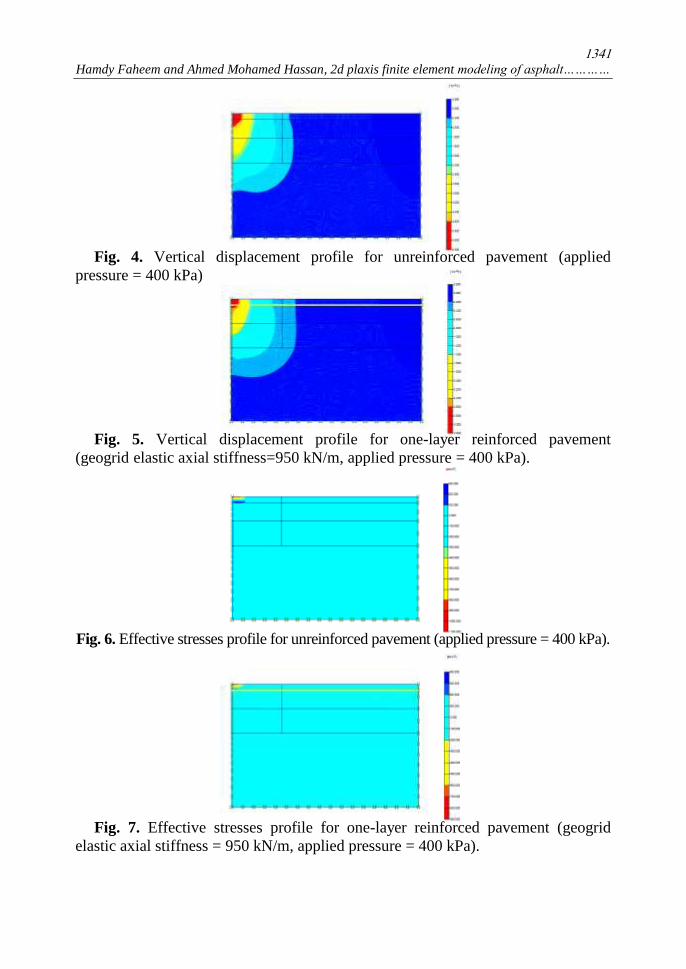
Figures 4 and 5 illustrate the vertical displacement profile for applied load of 400 kPa
for case of unreinforced pavement and reinforced pavement with one layer of geogrid of
elastic axial stiffness of 950 kPa placed under AC layer. It may be observed that a
significant decrease in vertical settlement obtained for reinforced pavement. Maximum
vertical displacement is 6x10⁻³
m, for case of unreinforced pavement, while it is 3.2x10⁻³
m
for reinforced base.
1341
Hamdy Faheem and Ahmed Mohamed Hassan, 2d plaxis finite element modeling of asphalt…………
Fig. 4. Vertical displacement profile for unreinforced pavement (applied
pressure = 400 kPa)
Fig. 5. Vertical displacement profile for one-layer reinforced pavement
(geogrid elastic axial stiffness=950 kN/m, applied pressure = 400 kPa).
Fig. 6. Effective stresses profile for unreinforced pavement (applied pressure = 400 kPa).
Fig. 7. Effective stresses profile for one-layer reinforced pavement (geogrid
elastic axial stiffness = 950 kN/m, applied pressure = 400 kPa).
1342
JES, Assiut University, Faculty of Engineering, Vol. 42, No. 6, November 2014, pp. 1336 – 1348
Figures 6 and 7 illustrate the effective stresses profiles for applied pressure of 400 kPa
for case of unreinforced pavement and reinforced pavement with one layer of geogrid of
elastic axial stiffness = 950 kN/m placed under AC layer. These figures depict that for
unreinforced pavement, maximum effective stress is significantly higher (1100 kPa)
compared with that for case of reinforced pavement (900 kPa).
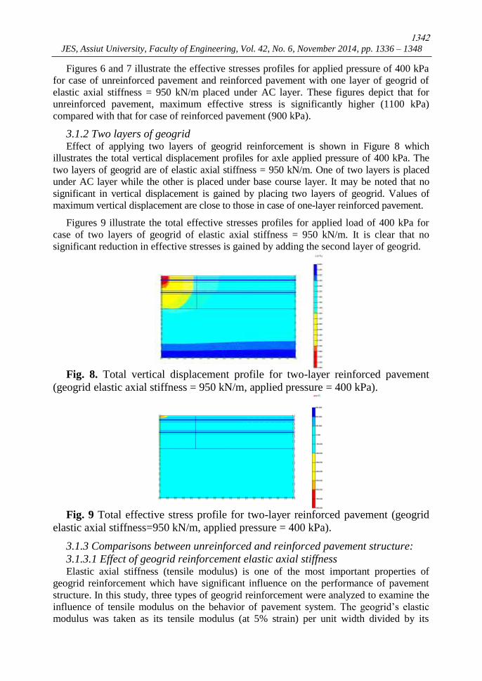
3.1.2 Two layers of geogrid Effect of applying two layers of geogrid reinforcement is shown in Figure 8 which
illustrates the total vertical displacement profiles for axle applied pressure of 400 kPa. The
two layers of geogrid are of elastic axial stiffness = 950 kN/m. One of two layers is placed
under AC layer while the other is placed under base course layer. It may be noted that no
significant in vertical displacement is gained by placing two layers of geogrid. Values of
maximum vertical displacement are close to those in case of one-layer reinforced pavement.
Figures 9 illustrate the total effective stresses profiles for applied load of 400 kPa for
case of two layers of geogrid of elastic axial stiffness = 950 kN/m. It is clear that no
significant reduction in effective stresses is gained by adding the second layer of geogrid.
Fig. 8. Total vertical displacement profile for two-layer reinforced pavement
(geogrid elastic axial stiffness = 950 kN/m, applied pressure = 400 kPa).
Fig. 9 Total effective stress profile for two-layer reinforced pavement (geogrid
elastic axial stiffness=950 kN/m, applied pressure = 400 kPa).
3.1.3 Comparisons between unreinforced and reinforced pavement structure:
3.1.3.1 Effect of geogrid reinforcement elastic axial stiffness Elastic axial stiffness (tensile modulus) is one of the most important properties of
geogrid reinforcement which have significant influence on the performance of pavement
structure. In this study, three types of geogrid reinforcement were analyzed to examine the
influence of tensile modulus on the behavior of pavement system. The geogrid’s elastic
modulus was taken as its tensile modulus (at 5% strain) per unit width divided by its
1343
Hamdy Faheem and Ahmed Mohamed Hassan, 2D plaxis finite element modeling of asphalt………
0
200
400
600
800
1000
1200
0 50 100 150 200 250 300 350 400 450 500
Ma
xim
um
Eff
ect
ive
Str
ess
(k
Pa
)
Applied Stress (kPa)
unreinforced
Eg = 213 kPa
Eg = 534 kPa
Eg = 950 kPa
Geogrid Elastic Axial Stiffeness
-12.0
-10.0
-8.0
-6.0
-4.0
-2.0
0.0
0.00 0.01 0.02 0.03 0.04 0.05 0.06 0.07 0.08 0.09 0.10
Ve
rtic
al
Se
ttle
me
nt
(mm
)
Time (s)
50 kPa
100 kPa
200 kPa
300 kPa
400 kPa
500 kPa
600 kPa
Stress Amplitude
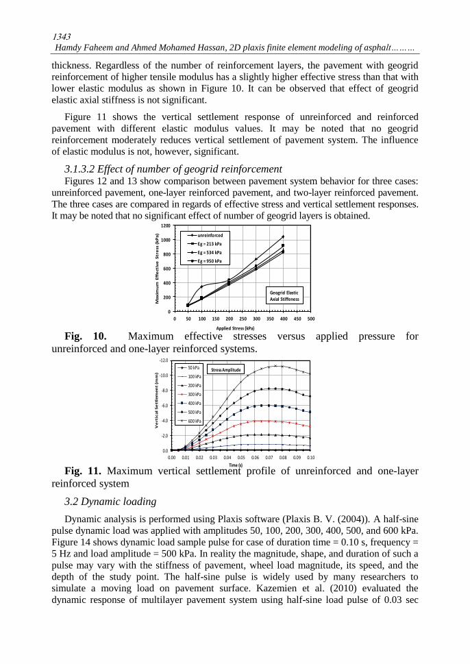
thickness. Regardless of the number of reinforcement layers, the pavement with geogrid
reinforcement of higher tensile modulus has a slightly higher effective stress than that with
lower elastic modulus as shown in Figure 10. It can be observed that effect of geogrid
elastic axial stiffness is not significant.
Figure 11 shows the vertical settlement response of unreinforced and reinforced
pavement with different elastic modulus values. It may be noted that no geogrid
reinforcement moderately reduces vertical settlement of pavement system. The influence
of elastic modulus is not, however, significant.
3.1.3.2 Effect of number of geogrid reinforcement Figures 12 and 13 show comparison between pavement system behavior for three cases:
unreinforced pavement, one-layer reinforced pavement, and two-layer reinforced pavement.
The three cases are compared in regards of effective stress and vertical settlement responses.
It may be noted that no significant effect of number of geogrid layers is obtained.
Fig. 10. Maximum effective stresses versus applied pressure for
unreinforced and one-layer reinforced systems.
Fig. 11. Maximum vertical settlement profile of unreinforced and one-layer
reinforced system
3.2 Dynamic loading
Dynamic analysis is performed using Plaxis software (Plaxis B. V. (2004)). A half-sine
pulse dynamic load was applied with amplitudes 50, 100, 200, 300, 400, 500, and 600 kPa.
Figure 14 shows dynamic load sample pulse for case of duration time = 0.10 s, frequency =
5 Hz and load amplitude = 500 kPa. In reality the magnitude, shape, and duration of such a
pulse may vary with the stiffness of pavement, wheel load magnitude, its speed, and the
depth of the study point. The half-sine pulse is widely used by many researchers to
simulate a moving load on pavement surface. Kazemien et al. (2010) evaluated the
dynamic response of multilayer pavement system using half-sine load pulse of 0.03 sec
1344
JES, Assiut University, Faculty of Engineering, Vol. 42, No. 6, November 2014, pp. 1336 – 1348
-0.35
-0.3
-0.25
-0.2
-0.15
-0.1
-0.05
0
0 0.01 0.02 0.03 0.04 0.05 0.06
Ve
rtic
al
Se
ttle
me
nt
(mm
)
Time (s)
Reinforced Base
Unreinforced Base
-7.00
-6.00
-5.00
-4.00
-3.00
-2.00
-1.00
0.000 50 100 150 200 250 300 350 400 450 500
Ma
xim
um
Ve
rtic
al
Se
ttle
me
nt
(mm
)
Applied Stress (kPa)
Unreinforced
One Geogrid Layer
Two Geogrid Layers
0
100
200
300
400
500
600
0.00 0.02 0.04 0.06 0.08 0.10 0.12
Load
(kN
)
Time (s)
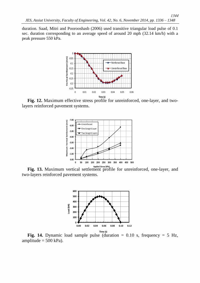
duration. Saad, Mitri and Poorooshasb (2006) used transitive triangular load pulse of 0.1
sec. duration corresponding to an average speed of around 20 mph (32.14 km/h) with a
peak pressure 550 kPa.
Fig. 12. Maximum effective stress profile for unreinforced, one-layer, and two-
layers reinforced pavement systems.
Fig. 13. Maximum vertical settlement profile for unreinforced, one-layer, and
two-layers reinforced pavement systems.
Fig. 14. Dynamic load sample pulse (duration = 0.10 s, frequency = 5 Hz,
amplitude = 500 kPa).
1345
Hamdy Faheem and Ahmed Mohamed Hassan, 2D plaxis finite element modeling of asphalt………
-12.0
-10.0
-8.0
-6.0
-4.0
-2.0
0.0
0.00 0.01 0.02 0.03 0.04 0.05 0.06 0.07 0.08 0.09 0.10
Ve
rtic
al
Se
ttle
me
nt
(mm
)
Time (s)
50 kPa
100 kPa
200 kPa
300 kPa
400 kPa
500 kPa
600 kPa
Stress Amplitude
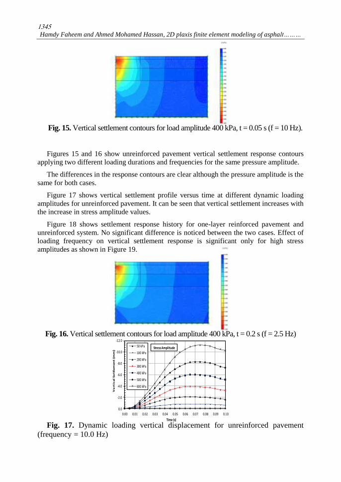
Fig. 15. Vertical settlement contours for load amplitude 400 kPa, t = 0.05 s (f = 10 Hz).
Figures 15 and 16 show unreinforced pavement vertical settlement response contours
applying two different loading durations and frequencies for the same pressure amplitude.
The differences in the response contours are clear although the pressure amplitude is the
same for both cases.
Figure 17 shows vertical settlement profile versus time at different dynamic loading
amplitudes for unreinforced pavement. It can be seen that vertical settlement increases with
the increase in stress amplitude values.
Figure 18 shows settlement response history for one-layer reinforced pavement and
unreinforced system. No significant difference is noticed between the two cases. Effect of
loading frequency on vertical settlement response is significant only for high stress
amplitudes as shown in Figure 19.
Fig. 16. Vertical settlement contours for load amplitude 400 kPa, t = 0.2 s (f = 2.5 Hz)
Fig. 17. Dynamic loading vertical displacement for unreinforced pavement
(frequency = 10.0 Hz)
1346
JES, Assiut University, Faculty of Engineering, Vol. 42, No. 6, November 2014, pp. 1336 – 1348
-14.0
-12.0
-10.0
-8.0
-6.0
-4.0
-2.0
0.0
0.0 5.0 10.0 15.0 20.0 25.0
Ma
xim
um
Ve
rtic
al
Se
ttle
me
nt
(mm
)
Frequency (Hz)
50 kPa 100 kPa200 kPa 300 kPa400 kPa 500 kPa600 kPa
Stress Amplitude
-0.35
-0.3
-0.25
-0.2
-0.15
-0.1
-0.05
0
0 0.01 0.02 0.03 0.04 0.05 0.06V
ert
ica
l S
ett
lem
en
t (m
m)
Time (s)
Reinforced Base
Unreinforced Base
Fig. 18. Effect of geogrid reinforcement vertical settlement response history.
Fig. 19. Effect of loading frequency on maximum vertical settlement for
dynamic loading.
4. Conclusions
A series of FE simulations have been carried out to evaluate the benefits of integrating a
high modulus geogrid into the pavement foundation. For the materials and loading
conditions used, the following conclusions can be drawn:
1. A significant improvement in pavement behavior is obtained by applying one-layer
of geogrid reinforcement. Vertical displacement and effective stress responses are
significantly lower for reinforced pavement system.
2. Effect of geogrid axial elastic stiffness is on reinforced pavement behavior is not significant.
3. No significant improvement in pavement system was gained by adding another
layer of geogrid to the pavement system.
4. For case of dynamic loading, no significant influence of geogrid reinforcement on
pavement behavior was observed.
5. Effect of dynamic loading frequency on pavement behavior is significant only for
high stress amplitude.
REFERENCES
[1] Pandey, S., Rao, K. R. and Tiwari, D.( 2012).” Effect of Geogrid Reinforcement on Critical
Responses of Bituminous Pavements.”, 25th ARRB Conference – Shaping the future:
Linking policy, research and outcomes, Perth, Australia.
[2] Howard, I.L. and Warren, K.A. (2009). “Finite-element modelling of instrumented flexible
pavements under stationary transient loading.” J. Transportation Eng. ASCE, 135(2): 53-61.
1347
Hamdy Faheem and Ahmed Mohamed Hassan, 2D plaxis finite element modeling of asphalt………
[3] Perkins, S. W. (2001). “Mechanistic-empirical modeling and design model development of
geosynthetic reinforced flexible pavements.” Montana Department of transportation,
Helena, Montana, Report No. FHWA/MT-01-002/99160-1A.
[4] Perkins, S. W. (2002). “Evaluation of geosynthetic reinforced flexible pavement systems
using two pavement test facilities.” Report No. FHWA/MT-02-008/20040, U.S.
Department of Transportation, Federal Highway Administration.
[5] Berg, R. R., Christopher, B.R., and Perkins, S.W. (2000). “Geosynthetic reinforcement of
the aggregate base course of flexible pavement structures.” GMA White paper II,
Geosynthetic material Association, Roseville, MN, USA, 130 p.
[6] Perkins, S. W., Ismeik, M. and Fogelsong, M. L. (1999). "Influence of geosynthetic
placement position on the performance of reinforced flexible pavement systems."
Proceedings of the Conference Geosynthetics ‘99, Boston, MA, USA, Vol. 1, pp. 253-264.
[7] Barksdale, R.D., Brown, S.F., and Chan, F. (1989). “Aggregate base reinforcement of
surfaced pavement” Geotext. Geomembrane, 8, pp.165–189.
[8] Virgili, A., Canestrari, F., Grilli, A. and Santagata, F.A. (2009). “Repeated load test on bituminous
systems reinforced by geosynthetics.” Geotextiles and Geomembranes Vol. 27, pp.187-195.
[9] Dondi, G., (1994). “Three-dimensional finite element analysis of a reinforced paved road.”
Proceedings of the Fifth International Conference on Geotextiles, Geomembrane and
Related Products, Singapore, pp. 95-100.
[10] Moayedi, H., Kazemian, S., Prasad, B. and Huat (2009). “Effect of Geogrid Reinforcement
Location in Paved Road Improvement.” Journal of EJGE, Vol.14, pp.3313-3329.
[11] Miura, N., Sakai, A., Taesiri, Y., Yamanouchi, T. and Yasuhara, K. (1990). “Polymer grid reinforced
pavement on soft clay grounds.” geotextiles and geomembranes, Vol. 9, No. 1, pp. 99-123.
[12] Wathugala, G. W., Huang, B., and Pal, S. (1996).“Numerical simulation of geosynthetic
reinforced flexible pavement.” Transportation Research Record 1534, Transportation
Research Board, national Research Council, Washington, DC, USA, pp.58-65.
[13] Leng, J., Gabr, M. A., 2005. “Numerical analysis of stress-deformation response in
reinforced unpaved road sections.” Geosynthetics International, Vol.12, No.2, pp.111-119.
[14] Nazzal, M. D., Abu-Farsakh, M. Y. and Mohammad, L. N. (2010). “Implementation of a
critical state two-surface model to evaluate the response of geosynthetic reinforced
pavements.” International Journal of Geomechanics, Vol. 10, No. 5, p202-212.
[15] Plaxis B. V. (2004). Plaxis 2D Version 8.2, Finite element code for soil and rock analysis,
A. A. Balkema, Delft, Netherlands.
[16] Kazemian, S., Barghchi, M., Prasad, A., Maydi, H. and Huat, B.K. (2010). “Reinforced
pavement above trench under urban traffic load: Case study and finite element (FE) analysis.”
Journal of Scientific Research and Essay Vol. 5 (21), Nov.4, 2010, pp. 3313- 3328.

1348
JES, Assiut University, Faculty of Engineering, Vol. 42, No. 6, November 2014, pp. 1336 – 1348
ستخدام العناصر متناهية الصغرإبعاد بالنمذجه ثنائية األ
سفلتى المسلح بالشبك الصناعىللرصف األ
:العربى ملخصال
غالبا ما يقترن إستخدم الشبك الصناعى لتسليح طبقات األساس الغير متماسكه للطرق وذلك لتحسين أداء
ية الصغر لتحليل سلوك الرصف البيتومينى الرصف المرن . هذا البحث يقدم نموذج متماثل للعناصر متناه
الغير مسلح والمسلح بالشبك الصناعى والمعرض ألحمال ثابته ومتحركه .
تم تحميل النموذج بزياده تدريجيه فى االحمال وتم تحديد استجابات الرصف الحرجه مثل اإلجهاد الفعال
مدعم بالشبك الصناعىالغير مدعم والوالهبوط الرأسى للسطح وذلك لكل من الرصف المرن
أظهرت النتائج إلى أنه أثناء الحمل الثابت لوحظ تأثير متوسط على سلوك الرصف نتيجة التدعيم بطبقه من
الشبك الصناعى , ولم يالحظ هذا التأثير فى حالة الحمل الديناميكى.
كان تأثير تردد الحمل الديناميكى ملحوظ على هبوط الرصف وخصوصا عند ذروة األحمال العاليه.
نه لم يتم الحصول على تحسن ملموس فى سلوك نظام الرصف عند إضافة طبقه أأوضحت النتائج ايضا
أخرى من الشبك الصناعى للتدعيم .