Embed Size (px)
Citation preview
GREE2000 SeriesGREE2000 SeriesGREE2000 SeriesGREE2000 SeriesGREE2000 Series
-47-
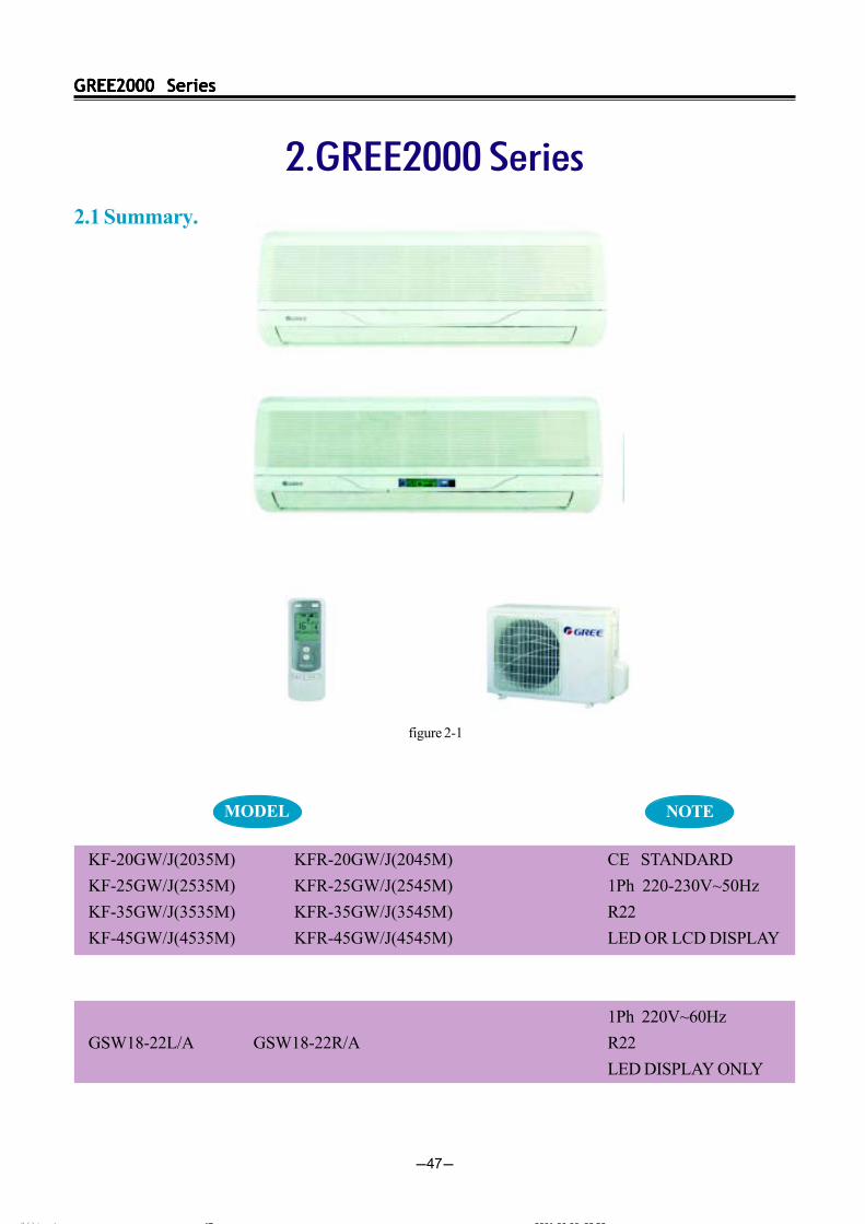
2.GREE2000 Series2.1 Summary.
KF-20GW/J(2035M) KFR-20GW/J(2045M)
KF-25GW/J(2535M) KFR-25GW/J(2545M)
KF-35GW/J(3535M) KFR-35GW/J(3545M)
KF-45GW/J(4535M) KFR-45GW/J(4545M)
GSW18-22L/A GSW18-22R/A
CE STANDARD
1Ph 220-230V~50Hz
R22
LED OR LCD DISPLAY
1Ph 220V~60Hz
R22
LED DISPLAY ONLY
figure 2-1
MODEL NOTE
ÄÚÒ³ 6 2001-06-06, 23:5247
GREE2000 SeriesGREE2000 SeriesGREE2000 SeriesGREE2000 SeriesGREE2000 Series
-48-
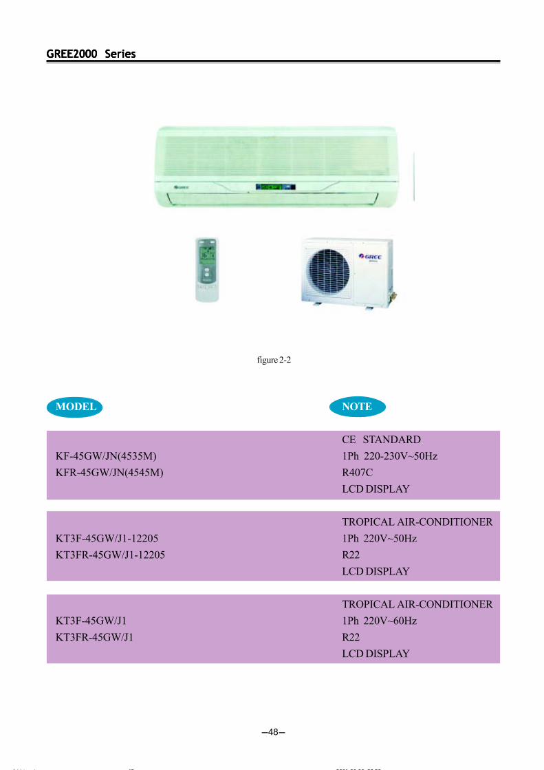
MODEL
KF-45GW/JN(4535M)
KFR-45GW/JN(4545M)
KT3F-45GW/J1-12205
KT3FR-45GW/J1-12205
KT3F-45GW/J1
KT3FR-45GW/J1
NOTE
CE STANDARD
1Ph 220-230V~50Hz
R407C
LCD DISPLAY
TROPICAL AIR-CONDITIONER
1Ph 220V~50Hz
R22
LCD DISPLAY
TROPICAL AIR-CONDITIONER
1Ph 220V~60Hz
R22
LCD DISPLAY
figure 2-2
ÄÚÒ³ 6 2001-06-06, 23:5248
GREE2000 SeriesGREE2000 SeriesGREE2000 SeriesGREE2000 SeriesGREE2000 Series
-49-
Function
Power supply
Rated input(W)
Rated current(A)
Air flow(m3/h)
Dehumidifying volume(L/h)
EER(W/W)Model
Motor fan speed(rpm)
Output power(W)
Fan type/piece
Diameter-length(mm)
Evaporator
Row-fin distance(mm)
Working area(m2)
Swing motor
Input power(W)
Fuse(A)
Working capacitor( F)
Noise(dB(A))
Dimension(width-height-depth)(mm)
Net weight(kg)
Model
Input power(W)
Current(A)
L.R.A.(A)
Throttling method
Compressor
Starting method
Working temp.
Condenser
Pipe-diameter
Row-fin distance(mm)
Working area(m2)
Fan motor power(w)/speed(rpm)
Type-piece
Diameter(mm)
Defrosting method
Noise (dB(A))
Dimension(width-height-depth)(mm)
Net weight(kg)
Refrigerant charge (kg)
Length (m)
Outer diameter ofconnecting pipe
Max distance
KFR-20GW/J(2045M)
Cooling
2000
6826
760
Heating
2300
1Ph 220-230V~50Hz
420
850/800/750
8
Cross flow fan-1
91mm-616
Aluminum fin-copper tube
2-1.5
0.18
MP24GA
2
Controller 3.15A Transformer 0.2A
1
34
830 285 189
11
15
Capillary
Capacitor staring
115
Aluminum fin-copper tube
9.52
2-1.4
0.65
38/720
Axial fan-1
400
Auto defrost
52
848 540 320
32
4
6(1/4”)
9.52(3/8”)
5
10
Indoor unit
Outdoor unit
Connecting
pipe
Liquid pipe(mm)Gas pipe(mm)Height(m)Length(m)
Model
Cooling
2000
6826
760
3.3
0.8
3.0KF-20G/(2035M) KFR-20G/(2045M)
KF-20W/J
729
3.06
SG333DB1
KFR-20W/J
729/789
3.06/3.16
SG433EB2
R22/0.7kg R22/0.8kg
W
(BTU/h)Capacity
Table 2-1
2.2 Technical specifications.
KF-20GW/J(2035M)
The technical date are subject to change without notice .Please refer to the nameplate of the unit.
ÄÚÒ³ 6 2001-06-06, 23:5249
GREE2000 SeriesGREE2000 SeriesGREE2000 SeriesGREE2000 SeriesGREE2000 Series
-50-
Function
Power supply
Rated input(W)
Rated current(A)
Air flow(m3/h)
Dehumidifying volume(L/h)
EER(W/W)Model
Motor fan speed(rpm)
Output power(W)
Fan type/piece
Diameter-length(mm)
Evaporator
Row-fin distance(mm)
Working area(m2)
Swing motor
Input power(W)
Fuse(A)
Working capacitor( F)
Noise(dB(A))
Dimension(width-height-depth)(mm)
Net weight(kg)
Model
Input power(W)
Current(A)
L.R.A.(A)
Throttling method
Compressor
Starting method
Working temp.
Condenser
Pipe-diameter
Row-fin distance(mm)
Working area(m2)
Fan motor power(w)/speed(rpm)
Type-piece
Diameter(mm)
Defrosting method
Noise (dB(A))
Dimension(width-height-depth)(mm)
Net weight(kg)
Refrigerant charge (kg)
Length (m)
Outer diameter ofconnecting pipe
Max distance
KFR-25GW/J(2545M)
Cooling
2500
8534
920
4.4
1.2
2.8
Heating
2800
9500
950
4.5
/
3.1
1Ph 220-230V~50Hz
420
900/850/800
8
Cross flow fan-1
91mm-616
Aluminum fin-copper tube
2-1.5
0.18
FN8E-PG
2
Controller 3.15A Transformer 0.2A
1
34
830 285 189
11
21
Capillary
Capacitor staring
115
Aluminum fin-copper tube
9.52
2-2.0
0.65
38/720
Axial fan-1
400
Auto defrost
56
848 540 320
32
4
6(1/4”)
9.52(3/8”)
5
10
Indoor unit
Outdoor unit
Connecting
pipe
Liquid pipe(mm)Gas pipe(mm)Height(m)Length(m)
Model
Cooling
2500
8534
920
4.4
1.2
2.8KF-25G/(2535M) KFR-25G/(2545M)
KF-25W/J
919
4.26
RH165VHAC
KFR-25W/J
919/949
4.26/4.36
RH174VHAC
R22/0.7kg R22/0.9kg
W
(BTU/h)Capacity
Table 2-2
KF-25GW/J(2535M)
The technical date are subject to change without notice .Please refer to the nameplate of the unit.
ÄÚÒ³ 6 2001-06-06, 23:5350
GREE2000 SeriesGREE2000 SeriesGREE2000 SeriesGREE2000 SeriesGREE2000 Series
-51-
Function
Power supply
Rated input(W)
Rated current(A)
Air flow(m3/h)
Dehumidifying volume(L/h)
EER(W/W)Model
Motor fan speed(rpm)
Output power(W)
Fan type/piece
Diameter-length(mm)
Evaporator
Row-fin distance(mm)
Working area(m2)
Swing motor
Input power(W)
Fuse(A)
Working capacitor( F)
Noise(dB(A))
Dimension(width-height-depth)(mm)
Net weight(kg)
Model
Input power(W)
Current(A)
L.R.A.(A)
Throttling method
Compressor
Starting method
Working temp.
Condenser
Pipe-diameter
Row-fin distance(mm)
Working area(m2)
Fan motor power(w)/speed(rpm)
Type-piece
Diameter(mm)
Defrosting method
Noise (dB(A))
Dimension(width-height-depth)(mm)
Net weight(kg)
Refrigerant charge (kg)
Length (m)
Outer diameter ofconnecting pipe
Max distance
KFR-35GW/J(3545M)
Cooling
3500
11945
1300
6.0
1.6
2.7
Heating
3800
12975
1300
6.0
/
3.0
1Ph 220-230V~50Hz
500
1050/1000/950
8
Cross flow fan-1
91mm-616
Aluminum fin-copper tube
2-1.5
0.18
MP24GA
2
Controller 3.15A Transformer 0.2A
1
36
830 285 189
11
31
Capillary
Capacitor staring
115
Aluminum fin-copper tube
9.52
2-1.4
0.65
38/720
Axial fan-1
400
Auto defrost
56
848 540 320
40
4
6(1/4”)
12(1/2”)
5
10
Indoor unit
Outdoor unit
Connecting
pipe
Liquid pipe(mm)Gas pipe(mm)Height(m)Length(m)
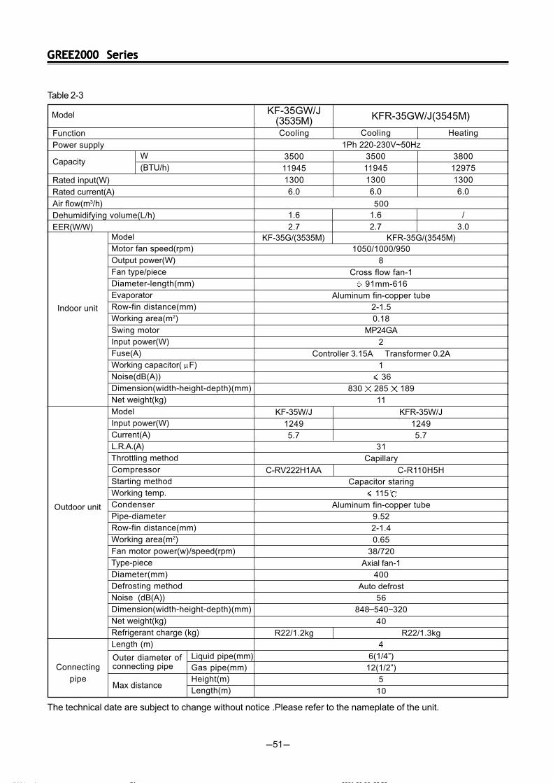
Model
Cooling
3500
11945
1300
6.0
1.6
2.7KF-35G/(3535M) KFR-35G/(3545M)
KF-35W/J
1249
5.7
C-RV222H1AA
KFR-35W/J
1249
5.7
C-R110H5H
R22/1.2kg R22/1.3kg
W
(BTU/h)Capacity
Table 2-3
KF-35GW/J(3535M)
The technical date are subject to change without notice .Please refer to the nameplate of the unit.
ÄÚÒ³ 6 2001-06-06, 23:5351

GREE2000 SeriesGREE2000 SeriesGREE2000 SeriesGREE2000 SeriesGREE2000 Series
-52-
Function
Power supply
Rated input(W)
Rated current(A)
Air flow(m3/h)
Dehumidifying volume(L/h)
EER(W/W)Model
Motor fan speed(rpm)
Output power(W)
Fan type/piece
Diameter-length(mm)
Evaporator
Row-fin distance(mm)
Working area(m2)
Swing motor
Input power(W)
Fuse(A)
Working capacitor( F)
Noise(dB(A))
Dimension(width-height-depth)(mm)
Net weight(kg)
Model
Input power(W)
Current(A)
L.R.A.(A)
Throttling method
Compressor
Starting method
Working temp.
Condenser
Pipe-diameter
Row-fin distance(mm)
Working area(m2)
Fan motor power(w)/speed(rpm)
Type-piece
Diameter(mm)
Defrosting method
Noise (dB(A))
Dimension(width-height-depth)(mm)
Net weight(kg)
Refrigerant charge (kg)
Length (m)
Outer diameter ofconnecting pipe
Max distance
KFR-45GW/J1(4545M)
Cooling
4500
15500
1700
7.73
2.0
2.6
Heating
4900
16500
1750
7.73
---
2.7
1Ph 220-230V~50Hz
650
1250/1150/1050
20
Cross flow fan-1
91mm-616
Aluminum fin-copper tube
2-1.4
0.18
MP24GA
2
Controller 3.15A Transformer 0.2A
1
46
830 285 189
11
35
Capillary
Capacitor staring
115
Aluminum fin-copper tube
9.52
2-1.4
0.4
36/880
Axial fan-1
400
Auto defrost
57
848 540 320
40
4
6(1/4”)
12(1/2”)
5
10
Indoor unit
Outdoor unit
Connecting
pipe
Liquid pipe(mm)Gas pipe(mm)Height(m)Length(m)
Model
Cooling
4500
15500
1700
7.73
2.0
2.6KF-45G/(4535M) KFR-45G/(4545M)
KF-45W/J
1669
7.6
PH290 2C-4FT1
KFR-45W/J
1669/1700
7.6/7.7
PH290 2C-4FT1
R22/1.3kg R22/1.3kg
W
(BTU/h)Capacity
Table 2-4
KF-45GW/J(4535M)
The technical date are subject to change without notice .Please refer to the nameplate of the unit.
ÄÚÒ³ 6 2001-06-06, 23:5352

GREE2000 SeriesGREE2000 SeriesGREE2000 SeriesGREE2000 SeriesGREE2000 Series
-53-
Function
Power supply
Rated input(W)
Rated current(A)
Air flow(m3/h)
Dehumidifying volume(L/h)
EER(W/W)Model
Motor fan speed(rpm)
Output power(W)
Fan type/piece
Diameter-length(mm)
Evaporator
Row-fin distance(mm)
Working area(m2)
Swing motor
Input power(W)
Fuse(A)
Working capacitor( F)
Noise(dB(A))
Dimension(width-height-depth)(mm)
Net weight(kg)
Model
Input power(W)
Current(A)
L.R.A.(A)
Throttling method
Compressor
Starting method
Working temp.
Condenser
Pipe-diameter
Row-fin distance(mm)
Working area(m2)
Fan motor power(w)/speed(rpm)
Type-piece
Diameter(mm)
Defrosting method
Noise dB(A)
Dimension(width-height-depth)(mm)
Net weight(kg)
Refrigerant charge (kg)
Length (m)
Outer diameter ofconnecting pipe
Max distance
GSW18-22R/A
Cooling
4500
15500
1700
7.73
2.0
2.6
Heating
4900
16500
1750
7.73
---
2.7
1Ph 220V 60Hz
650
1250/1150/1050
20
Cross flow fan-1
91mm-616
Aluminum fin-copper tube
2-1.4
0.18
MP24GA
2
Controllor 3.15A Transformer 0.2A
1
44
830 285 189
11
35
Capillary
Capacitor staring
115
Aluminum fin-copper tube
9.52
2-1.6
0.4
48/880
Axial fan-1
400
Auto defrost
<57
848 540 320
40
4
6(1/4”)
12(1/2”)
5
10
Indoor unit
Outdoor unit
Connecting
pipe
Liquid pipe(mm)Gas pipe(mm)Height(m)Length(m)
Model
Cooling
4500
15500
1700
7.73
2.0
2.6GSW18-22L/A(I) GSW18-22R/A(I)
GSW18-22L/A(O)
1669
7.6
2K25S236AHA
GSW18-22R/A(O)
1669/1700
7.6/7.7
2K25S236AHA
R22/1.2 R22/1.2
W
(BTU/h)Capacity
Table 2-5
GSW18-22L/A
The technical date are subject to change without notice .Please refer to the nameplate of the unit.
ÄÚÒ³ 6 2001-06-06, 23:5353
GREE2000 SeriesGREE2000 SeriesGREE2000 SeriesGREE2000 SeriesGREE2000 Series
-54-
Function
Power supply
Capacity
Rated input(W)
Rated current(A)
Air flow(m3/h)
Dehumidifying volume(L/h)
EER(W/W)Model
Motor fan speed(rpm)
Output power(W)
Fan type/piece
Diameter-length(mm)
Evaporator
Row-fin distance(mm)
Working area(m2)
Swing motor
Input power(W)
Fuse(A)
Working capacitor( F)
Noise(dB(A))
Dimension(width-height-depth)mm
Net weight(kg)
Model
Input power(W)
Current(A)
L.R.A.(A)
Throttling method
Compressor
Starting method
Working temp.
Condenser
Pipe-diameter
Row-fin distance(mm)
Working area(m2)
Fan motor power(w)/speed(rpm)
Type-piece
Diameter(mm)
Defrosting method
Noise dB(A)
Dimension(mm)(width-height-depth)
Net weight(kg)
Refrigerant charge (kg)
Length(m)
Indoor unit
Outdoor unit
(W)
Model KFR-45GW/JW(4545M)
Cooling
4500
1880
9.2
650
2.0
2.14
Heating
5200
1980
9.3
---
2.17
1Ph 220-230V~50Hz
1250/1150/1050
20
Cross flow fan-1
91mm-616
Aluminum fin-copper tube
2-1.4
0.18
MP24GA
2
Controller 3.15A Transformer 0.2A
1
46
830 285 189
11
35
Capillary
Capacitor staring
115
Aluminum fin-copper tube
9.52
2-1.7
0.4
60/780
Axial fan-1
460
Auto defrost
<58
950 710 410
59
4
6(1/4”)
12(1/2”)
5
10
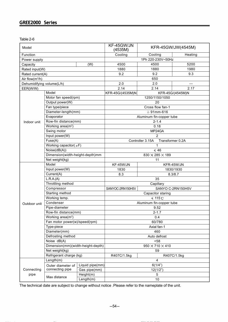
Cooling
4500
1880
9.2
2.0
2.14KFR-45G/(4535M)N KFR-45G/(4545M)N
KF-45W/JN
1830
8.3
SANYO C-2RN150H5V
KFR-45W/JN
1830/1930
8.3/8.7
SANYO C-2RN150H5V
R407C/1.5kg R407C/1.5kg
Outer diameter ofconnecting pipe
Max distance
Connecting
pipe
Liquid pipe(mm)Gas pipe(mm)Height(m)Length(m)
Table 2-6
KF-45GW/JN(4535M)
The technical date are subject to change without notice .Please refer to the nameplate of the unit.
ÄÚÒ³ 6 2001-06-06, 23:5354
GREE2000 SeriesGREE2000 SeriesGREE2000 SeriesGREE2000 SeriesGREE2000 Series
-55-
Function
Power supply
Capacity
Rated input(W)
Rated current(A)
Air flow(m3/h)
Dehumidifying volume(L/h)
EER(W/W)Model
Motor fan speed(r/min)
Output power(W)
Fan type/piece
Diameter-length(mm)
Evaporator
Row-fin distance(mm)
Working area(m2)
Swing motor
Input power(W)
Fuse(A)
Working capacitor( F)
Noise(dB(A))
Dimension(width-height-depth)mm
Net weight(kg)
Model
Input power(W)
Current(A)
L.R.A.(A)
Throttling method
Compressor
Starting method
Working temp.
Condenser
Pipe-diameter
Row-fin distance(mm)
Working area(m2)
Fan motor power(w)/speed(rpm)
Type-piece
Diameter(mm)
Defrosting method
Noise dB(A)
Dimension(mm)(width-height-depth)
Net weight(kg)
Refrigerant charge (kg)
Length
Indoor unit
Outdoor unit
(W)
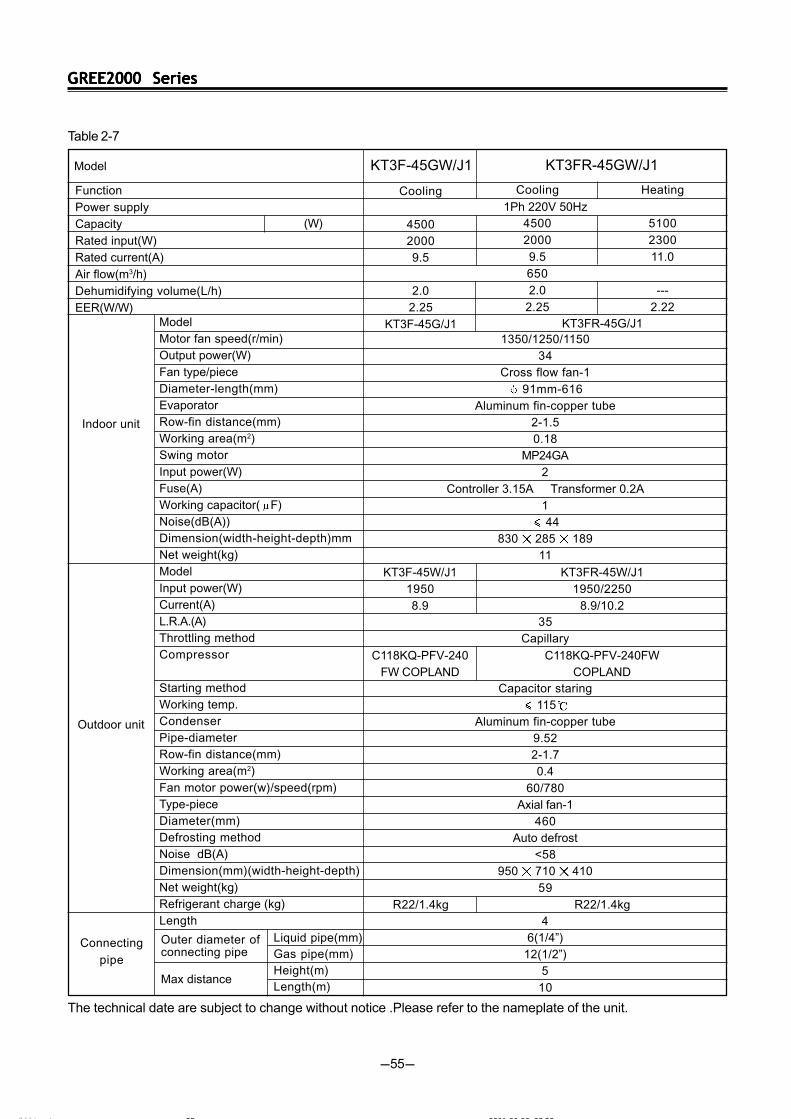
Model KT3FR-45GW/J1
Cooling
4500
2000
9.5
650
2.0
2.25
Heating
5100
2300
11.0
---
2.22
1Ph 220V 50Hz
1350/1250/1150
34
Cross flow fan-1
91mm-616
Aluminum fin-copper tube
2-1.5
0.18
MP24GA
2
Controller 3.15A Transformer 0.2A
1
44
830 285 189
11
35
Capillary
Capacitor staring
115
Aluminum fin-copper tube
9.52
2-1.7
0.4
60/780
Axial fan-1
460
Auto defrost
<58
950 710 410
59
4
6(1/4”)
12(1/2”)
5
10
Cooling
4500
2000
9.5
2.0
2.25
KT3F-45G/J1 KT3FR-45G/J1
KT3F-45W/J1
1950
8.9
C118KQ-PFV-240
FW COPLAND
KT3FR-45W/J1
1950/2250
8.9/10.2
C118KQ-PFV-240FW
COPLAND
R22/1.4kg R22/1.4kg
Outer diameter ofconnecting pipe
Max distance
Connecting
pipe
Liquid pipe(mm)Gas pipe(mm)Height(m)Length(m)
KT3F-45GW/J1
Table 2-7
The technical date are subject to change without notice .Please refer to the nameplate of the unit.
ÄÚÒ³ 6 2001-06-06, 23:5355
GREE2000 SeriesGREE2000 SeriesGREE2000 SeriesGREE2000 SeriesGREE2000 Series
-56-
Function
Power supply
Capacity
Rated input(W)
Rated current(A)
Air flow(m3/h)
Dehumidifying volume(L/h)
EER(W/W)Model
Motor fan speed(r/min)
Output power(W)
Fan type/piece
Diameter-length(mm)
Evaporator
Row-fin distance(mm)
Working area(m2)
Swing motor
Input power(W)
Fuse(A)
Working capacitor( F)
Noise(dB(A))
Dimension(width-height-depth)mm
Net weight(kg)
Model
Input power(W)
Current(A)
L.R.A.(A)
Throttling method
Compressor
Starting method
Working temp.
Condenser
Pipe-diameter
Row-fin distance(mm)
Working area(m2)
Fan motor power(w)/speed(rpm)
Type-piece
Diameter(mm)
Defrosting method
Noise dB(A)
Dimension(mm)(width-height-depth)
Net weight(kg)
Refrigerant charge (kg)
Length
Indoor unit
Outdoor unit
(W)
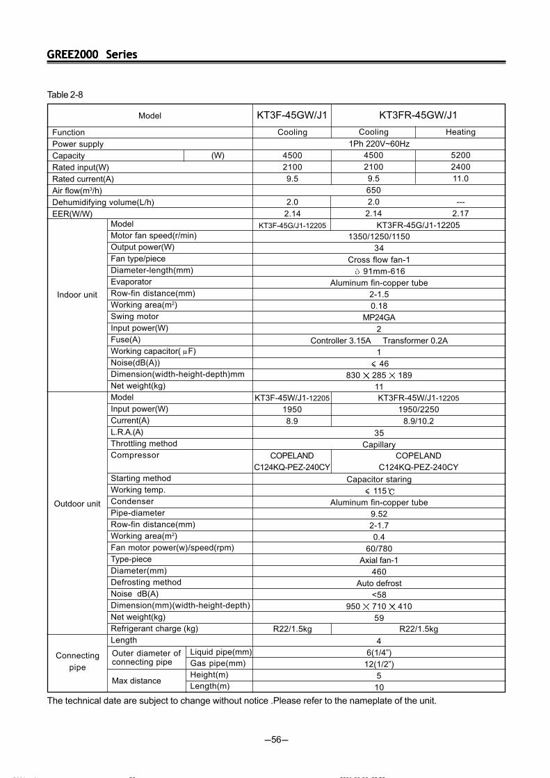
Model KT3FR-45GW/J1
Cooling
4500
2100
9.5
650
2.0
2.14
Heating
5200
2400
11.0
---
2.17
1Ph 220V~60Hz
1350/1250/1150
34
Cross flow fan-1
91mm-616
Aluminum fin-copper tube
2-1.5
0.18
MP24GA
2
Controller 3.15A Transformer 0.2A
1
46
830 285 189
11
35
Capillary
Capacitor staring
115
Aluminum fin-copper tube
9.52
2-1.7
0.4
60/780
Axial fan-1
460
Auto defrost
<58
950 710 410
59
4
6(1/4”)
12(1/2”)
5
10
Cooling
4500
2100
9.5
2.0
2.14
KT3F-45G/J1-12205 KT3FR-45G/J1-12205
KT3F-45W/J1-12205
1950
8.9
COPELAND
C124KQ-PEZ-240CY
KT3FR-45W/J1-12205
1950/2250
8.9/10.2
COPELAND
C124KQ-PEZ-240CY
R22/1.5kg R22/1.5kg
Outer diameter ofconnecting pipe
Max distance
Connecting
pipe
Liquid pipe(mm)Gas pipe(mm)Height(m)Length(m)
KT3F-45GW/J1
Table 2-8
The technical date are subject to change without notice .Please refer to the nameplate of the unit.
ÄÚÒ³ 6 2001-06-06, 23:5356
GREE2000 SeriesGREE2000 SeriesGREE2000 SeriesGREE2000 SeriesGREE2000 Series
-57-
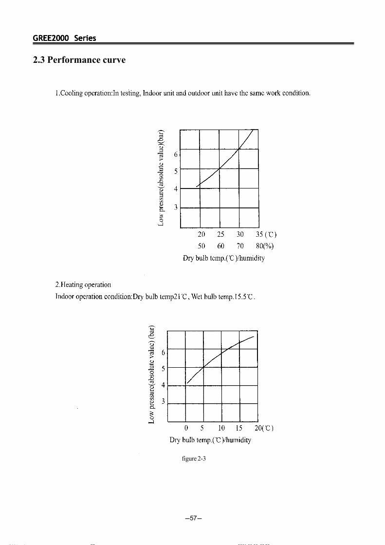
2.3 Performance curve
figure 2-3
ÄÚÒ³ 6 2001-06-06, 23:5357
GREE2000 SeriesGREE2000 SeriesGREE2000 SeriesGREE2000 SeriesGREE2000 Series
-58-
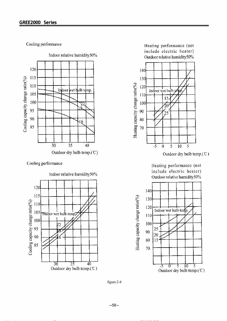
figure 2-4
ÄÚÒ³ 6 2001-06-06, 23:5358
GREE2000 SeriesGREE2000 SeriesGREE2000 SeriesGREE2000 SeriesGREE2000 Series
-59-
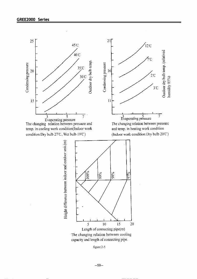
figure 2-5
ÄÚÒ³ 6 2001-06-06, 23:5359
GREE2000 SeriesGREE2000 SeriesGREE2000 SeriesGREE2000 SeriesGREE2000 Series
-60-
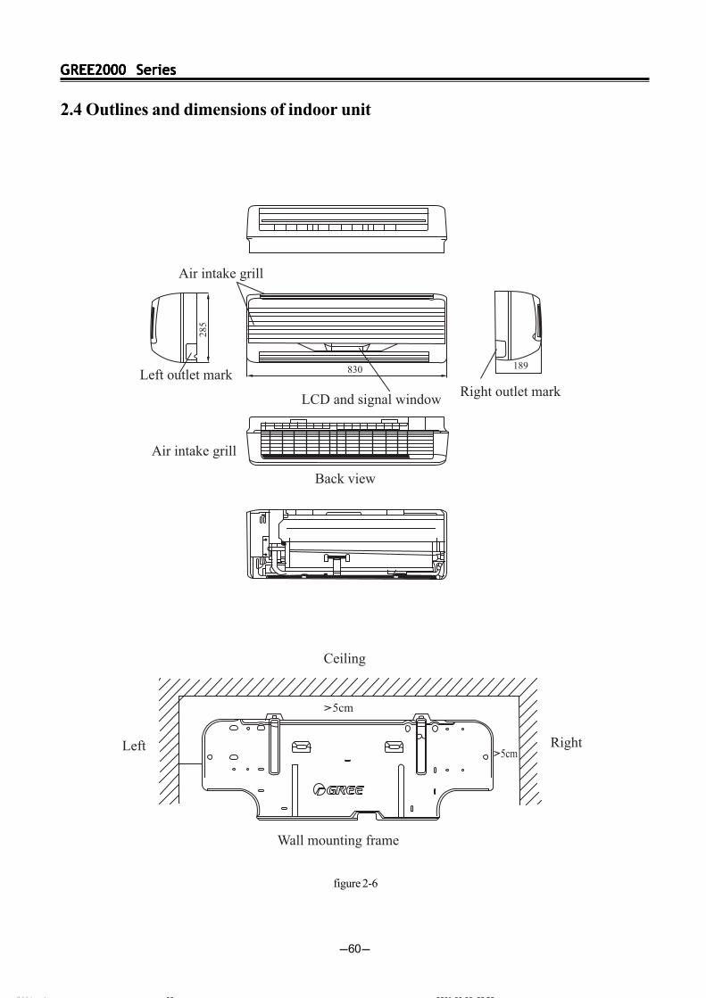
2.4 Outlines and dimensions of indoor unit
figure 2-6
ÄÚÒ³ 6 2001-06-06, 23:5360
GREE2000 SeriesGREE2000 SeriesGREE2000 SeriesGREE2000 SeriesGREE2000 Series
-61-
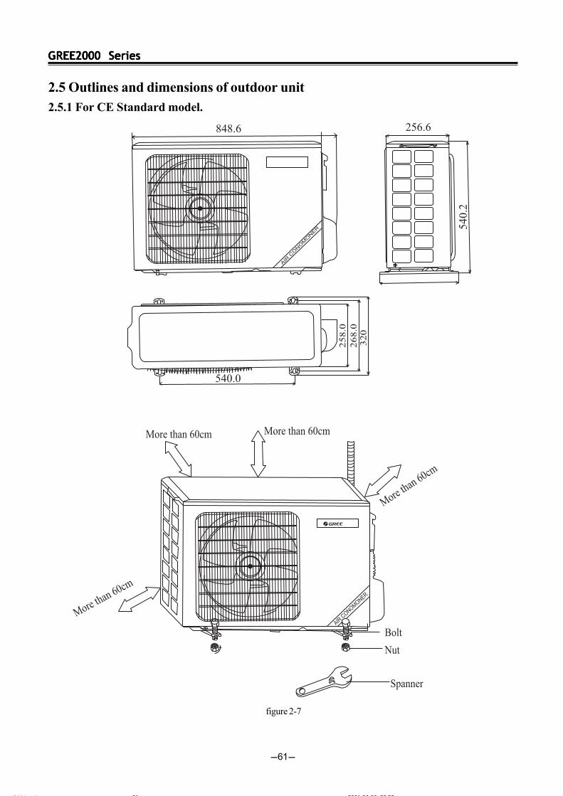
2.5 Outlines and dimensions of outdoor unit2.5.1 For CE Standard model.
figure 2-7
ÄÚÒ³ 6 2001-06-06, 23:5361
GREE2000 SeriesGREE2000 SeriesGREE2000 SeriesGREE2000 SeriesGREE2000 Series
-62-
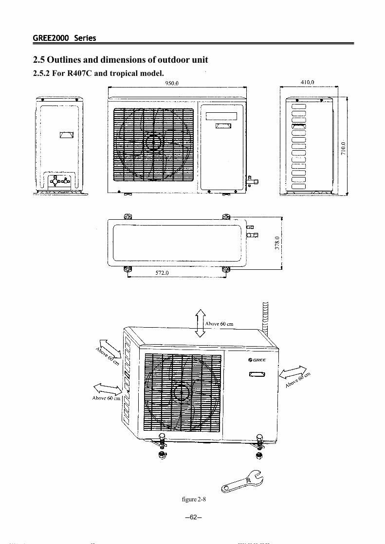
2.5 Outlines and dimensions of outdoor unit2.5.2 For R407C and tropical model.
figure 2-8
ÄÚÒ³ 6 2001-06-06, 23:5362

GREE2000 SeriesGREE2000 SeriesGREE2000 SeriesGREE2000 SeriesGREE2000 Series
-63-
2.6 Explosive view for indoor unit
figure 2-9
ÄÚÒ³ 6 2001-06-06, 23:5363
GREE2000 SeriesGREE2000 SeriesGREE2000 SeriesGREE2000 SeriesGREE2000 Series
-64-
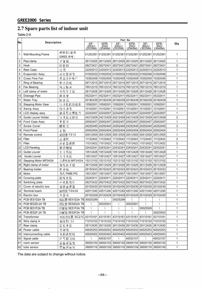
No. DescriptionPart No
Qty
1 Wall-Mounting Frame(
01252381 01252381 01252381 01252381 01252381 01252381 1GREE
2 Pipe clamp 26112425 26112425 26112425 26112425 26112425 26112425 1
3 Hook 26272421 26272421 26272421 26272421 26272421 26272421 2
4 Rear Case 22202013 22202013 22202013 22202013 22202013 22202013 1
5 Evaporator Assy 01002032 01002032 01002032 01002032 01002046 01002046 1
6 Cross Flow Fan 10352405 10352405 10352405 10352405 10352405 10352405 1
7 Ring of Bearing 26712015 26712015 26712015 26712015 26712015 26712015 1
8 Fan Bearing 76512210 76512210 76512210 76512210 76512210 76512210 1
9 Left clamp of motor 26112428 26112428 26112428 26112428 26112428 26112428 1
10 Drainage Pipe 05232411 05232411 05232411 05232411 05232411 05232411 1
11 Water Tray 20182439 20182439 20182439 20182439 20182439 20182439 1
12 Stepping Motor Gear 10592001 10592001 10592001 10592001 10592001 10592001 1
13 Swing Assy 10102001 10102001 10102001 10102001 10102001 10102001 1
14 LCD display assy 22242007 22242007 22242007 22242007 22242007 22242007 1
15 Guide Louver Holder 24212429 24212429 24212429 24212429 24212429 24212429 2
16 Front Case Assy 20002407 20002407 20002407 20002407 20002407 20002407 1
17 Screw Cover 24252440 24252440 24252440 24252440 24252440 24252440 3
18 Front Panel 20002404 20002404 20002404 20002404 20002404 20002404 1
19 Remote control Y 5 1 2 30512505 30512505 30512505 30512505 30512505 30512505 1
20 Filter 11122443 11122443 11122443 11122443 11122443 11122443 2
21 Filter 11012422 11012422 11012422 11012422 11012422 11012422 2
22 LCD Paneling 22432241 22432241 22432241 22432241 22432241 22432241 1
23 Guide Louver 10512428 10512428 10512428 10512428 10512428 10512428 1
24 Guide Louver 10512427 10512427 10512427 10512427 10512427 10512427 1
25 Stepping Motor MP24GA MP24GA 15212102 15212102 15212102 15212102 15212102 15212102 1
26 Right clamp of motor 26112429 26112429 26112429 26112429 26112429 26112429 1
27 Bearing holder 26152423 26152423 26152423 26152423 26152423 26152423 1
28 Motor FN8E-PG 15012007 15012007 15012007 15012007 15012007 15012007 1
29 Covering plate 22242411 22242411 22242411 22242411 22242411 22242411 1
30 Switching plate 26272422 26272422 26272422 26272422 26272422 26272422 1
31 Cover of electric box 20102430 20102430 20102430 20102430 20102430 20102430 1
32 Terminal board T4A3A 42011240 42011240 42011240 42011240 42011240 42011240 1
33 Electric box 20102429 20102429 20102429 20102429 20102429 20102429 1
34 PCB 5E51D2A TB 5E51D2A TB 30025299 \ 30025299 \ \ \ 1
34 PCB 5E52D-2A TB 5E52D2A TB \ 30025501 \ 30025501 \ \ 1
34 PCB 5E51F2A TB 5E51F2A TB \ \ \ \ 30025500 \ 1
34 PCB 5E52F-2A TB 5E52F2A TB \ \ \ \ \ 30025502 1
35 Transformer SC21C 43110161 43110161 43110161 43110161 43110161 43110161 1
36 Wire clamp A ( ) 71010103 71010103 71010103 71010103 71010103 71010103 1
37 Rear clamp 26112430 26112430 26112430 26112430 26112430 26112430 1
38 Power cable 40020202 40020202 40020202 40020202 40020203 40020203 1
39 Interconnecting cable 40020402 40020402 40020402 40020402 40020403 40020403 1
40 Signal cable \ 40032107 \ 40032107 \ 40032107 1
41 room sensor 39000155 39000155 39000155 39000155 39000155 39000155 1
42 tube sensor 39000116 39000159 39000116 39000159 39000116 39000159 1
KF-20G/J
(2035M)
KFR-20G/
(2045M)
KF-25G/J
(2535M)
KFR-20G/
(2545M)
KF-35G/J
(3535M)
KFR-35G/
(3545M)
2.7 Spare parts list of indoor unitTable 2-9
The data are subject to change without notice.
ÄÚÒ³ Î ¼Û ñ 6 2001-06-06, 23:5764
GREE2000 SeriesGREE2000 SeriesGREE2000 SeriesGREE2000 SeriesGREE2000 Series
-65-
De
sc
rip
tio
nP
art
N
o
Qty
1W
all-M
ount
ing
Fra
me
(G
REE
0125
2381
0125
2381
0125
2381
0125
2381
0125
2381
0125
2381
0125
2381
0125
2381
1
2P
ipe
clam
p26
1124
2526
1124
2526
1124
2526
1124
2526
1124
2526
1124
2526
1124
2526
1124
251
3H
ook
2627
2421
2627
2421
2627
2421
2627
2421
2627
2421
2627
2421
2627
2421
2627
2421
2
4R
ear C
ase
2220
2013
2220
2013
2220
2013
2220
2013
2220
2013
2220
2013
2220
2013
2220
2013
1
5E
vapo
rato
r A
ssy
0100
2017
0100
2017
0100
2017
0100
2017
0100
2017
0100
2017
0100
2017
0100
2017
1
6C
ross
Flo
w F
an10
3524
0510
3524
0510
3524
0510
3524
0510
3524
0510
3524
0510
3524
0510
3524
051
7R
ing
of B
earin
g26
7120
1526
7120
1526
7120
1526
7120
1526
7120
1526
7120
1526
7120
1526
7120
151
8F
an B
earin
g76
5122
1076
5122
1076
5122
1076
5122
1076
5122
1076
5122
1076
5122
1076
5122
101
9Le
ft cl
amp
of m
otor
2611
2428
2611
2428
2611
2428
2611
2428
2611
2428
2611
2428
2611
2428
2611
2428
1
10D
rain
age
Pip
e05
2324
1105
2324
1105
2324
1105
2324
1105
2324
1105
2324
1105
2324
1105
2324
111
11W
ater
Tra
y20
1824
3920
1824
3920
1824
3920
1824
3920
1824
3920
1824
3920
1824
3920
1824
391
12S
tepp
ing
Mot
or G
ear
1059
2001
1059
2001
1059
2001
1059
2001
1059
2001
1059
2001
1059
2001
1059
2001
1
13S
win
g A
ssy
1010
2001
1010
2001
1010
2001
1010
2001
1010
2001
1010
2001
1010
2001
1010
2001
1
14LC
D d
ispl
ay a
ssy
2224
2007
2224
2007
2224
2007
2224
2007
2224
2007
2224
2007
2224
2007
2224
2007
1
15G
uide
Lou
ver H
olde
r24
2124
2924
2124
2924
2124
2924
2124
2924
2124
2924
2124
2924
2124
2924
2124
292
16F
ront
Cas
e A
ssy
2000
2407
2000
2407
2000
2407
2000
2407
2000
2407
2000
2407
2000
2407
2000
2407
1
17S
cre
w C
ove
r24
2524
4024
2524
4024
2524
4024
2524
4024
2524
4024
2524
4024
2524
4024
2524
403
18F
ront
Pan
el20
0024
0420
0024
0420
0024
0420
0024
0420
0024
0420
0024
0420
0024
0420
0024
041
19R
emot
e co
ntro
lY
51
230
5125
0530
5125
0530
5125
0530
5125
0530
5125
0530
5125
0530
5125
0530
5125
051
20F
ilter
1112
2443
1112
2443
1112
2443
1112
2443
1112
2443
1112
2443
1112
2443
1112
2443
2
21F
ilter
1101
2422
1101
2422
1101
2422
1101
2422
1101
2422
1101
2422
1101
2422
1101
2422
2
22LC
D P
anel
ing
2243
2439
2243
2439
2243
2439
2243
2439
2243
2241
2243
2241
2243
2241
2243
2241
1
23G
uide
Lou
ver
1051
2428
1051
2428
1051
2428
1051
2428
1051
2428
1051
2428
1051
2428
1051
2428
1
24 G
uide
Lou
ver
1051
2427
1051
2427
1051
2427
1051
2427
1051
2427
1051
2427
1051
2427
1051
2427
1
25S
tepp
ing
Mot
or M
P24
GA
MP
24G
A15
2121
0215
2121
0215
2121
0215
2121
0215
2121
0215
2121
0215
2121
0215
2121
021
26R
ight
cla
mp
of m
otor
2611
2429
2611
2429
2611
2429
2611
2429
2611
2429
2611
2429
2611
2429
2611
2429
1
27B
earin
g ho
lder
2615
2423
2615
2423
2615
2423
2615
2423
2615
2423
2615
2423
2615
2423
2615
2423
1
28M
otor
FN
20G
-PG
FN
20G
-PG
1501
2022
1501
2022
1501
2022
1501
2022
1501
2022
1501
2022
\\
1
Mot
or F
N20
H-P
G F
N20
H-P
G\
\\
\\
\15
0120
2715
0120
271
29C
over
ing
plat
e22
2424
1122
2424
1122
2424
1122
2424
1122
2424
1122
2424
1122
2424
1122
2424
111
30S
witc
hing
pla
te26
2724
2226
2724
2226
2724
2226
2724
2226
2724
2226
2724
2226
2724
2226
2724
221
31C
over
of e
lect
ric b
ox20
1024
3020
1024
3020
1024
3020
1024
3020
1024
3020
1024
3020
1024
3020
1024
301
32Te
rmin
al b
oard
T4B
3AT
4B
3A
4201
1233
4201
1233
4201
1233
4201
1233
4201
1233
4201
1233
\\
1
32Te
rmin
al b
oard
GT
4B3A
1G
T4B
3A
1\
\\
\\
\42
0110
3042
0110
301
33E
lect
ric b
ox20
1024
2920
1024
2920
1024
2920
1024
2920
1024
2920
1024
2920
1024
2920
1024
291
KF
-45
G/J
(45
35
M)
LCD
KF
R-4
5G
/J(4
54
5M
)LC
D
KF
-45
G/
(35
35
M)N
KF
-45
G/
(45
35
M)
LED
KF
R-4
5G
/(4
54
5M
)LE
D
KF
R-4
5G
/
(45
45
M)N
GS
W1
8-
22
L/A
(I)
GS
W1
8-
22
R/A
(I)
Tabl
e 2-
10
The
dat
a ar
e su
bjec
t to
chan
ge w
ithou
t not
ice.
ÄÚÒ³ Î ¼Û ñ 6 2001-06-06, 23:5865
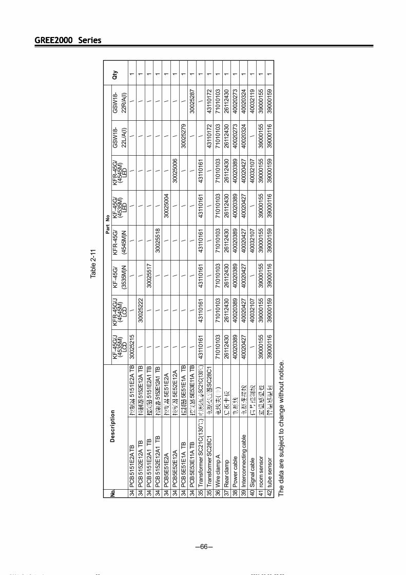
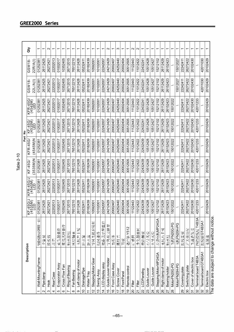
GREE2000 SeriesGREE2000 SeriesGREE2000 SeriesGREE2000 SeriesGREE2000 Series
-66-
Pa
rt
No
Qty
34P
CB
515
1E2A
TB
515
1E2A
TB
3002
5215
\\
\\
\\
\1
34P
CB
515
2E12
A T
B 5
152E
12A
TB
\30
0252
22\
\\
\\
\1
34P
CB
515
1E2A
1 T
B 5
151E
2A1
TB\
\30
0255
17\
\\
\\
1
34P
CB
515
2E12
A1
TB
515
2E12
A1
TB\
\\
3002
5518
\\
\\
1
34P
CB
5E
51E
2A 5
E51
E2A
\\
\\
3002
5004
\\
\1
34P
CB
5E
52E
12A
5E
52E
12A
\\
\\
\30
0250
06\
\1
34P
CB
5E
51E
1A T
B 5
E51
E1A
T
B\
\\
\\
\30
0252
79\
1
34P
CB
5E
53E
11A
TB
5E
53E
11A
TB
\\
\\
\\
\30
0252
871
35T
rans
form
er S
C21
C(1
30)
SC21
C(13
0)
4311
0161
4311
0161
4311
0161
4311
0161
4311
0161
4311
0161
\\
1
35T
rans
form
er S
C28
C1
SC
28C
1\
\\
\\
\43
1101
7243
1101
721
36W
ire c
lam
p A
()
7101
0103
7101
0103
7101
0103
7101
0103
7101
0103
7101
0103
7101
0103
7101
0103
1
37R
ear c
lam
p26
1124
3026
1124
3026
1124
3026
1124
3026
1124
3026
1124
3026
1124
3026
1124
301
38P
ower
cab
le40
0203
8940
0203
8940
0203
8940
0203
8940
0203
8940
0203
8940
0202
7340
0202
731
39In
terc
onne
ctin
g ca
ble
4002
0427
4002
0427
4002
0427
4002
0427
4002
0427
4002
0427
4002
0324
4002
0324
1
40S
igna
l cab
le\
4003
2107
\40
0321
07\
4003
2107
\40
0321
191
41ro
om s
enso
r39
0001
5539
0001
5539
0001
5539
0001
5539
0001
5539
0001
5539
0001
5539
0001
551
42tu
be s
enso
r39
0001
1639
0001
5939
0001
1639
0001
5939
0001
1639
0001
5939
0001
1639
0001
591
KF
-45G
/J(4
535M
)LC
D
KF
R-4
5G/J
(454
5M)
LCD
KF
-45G
/
(353
5M)N
KF
-45G
/(4
535M
)LE
D
KF
R-4
5G/
(454
5M)
LED
KF
R-4
5G/
(454
5M)N
GS
W18
-
22L/
A(I
)
GS
W18
-
22R
/A(I)
Tabl
e 2-
11
De
sc
rip
tio
n
The
dat
a ar
e su
bjec
t to
chan
ge w
ithou
t not
ice.
No.
ÄÚÒ³ Î ¼Û ñ 6 2001-06-06, 23:5866
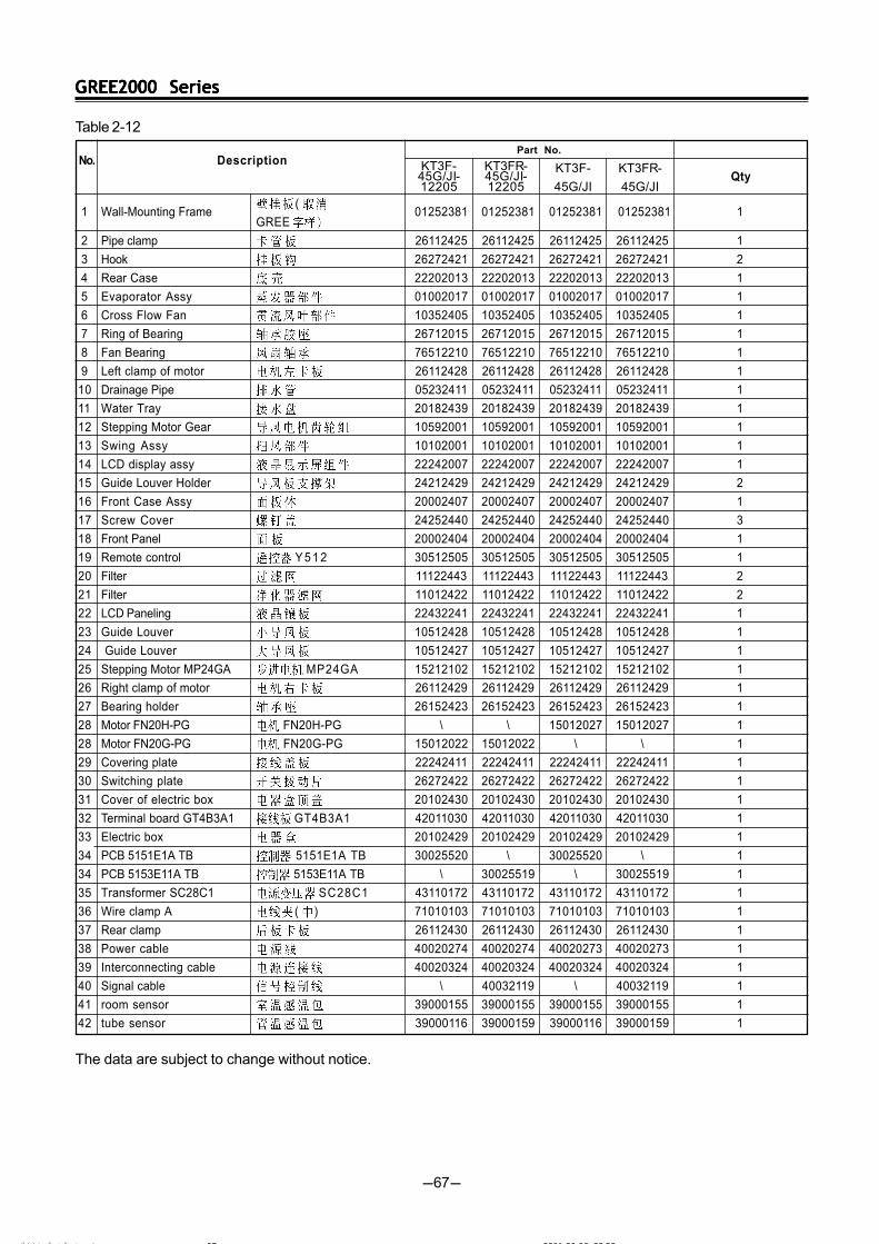
GREE2000 SeriesGREE2000 SeriesGREE2000 SeriesGREE2000 SeriesGREE2000 Series
-67-
1 Wall-Mounting Frame(
01252381 01252381 01252381 01252381 1GREE
2 Pipe clamp 26112425 26112425 26112425 26112425 1
3 Hook 26272421 26272421 26272421 26272421 2
4 Rear Case 22202013 22202013 22202013 22202013 1
5 Evaporator Assy 01002017 01002017 01002017 01002017 1
6 Cross Flow Fan 10352405 10352405 10352405 10352405 1
7 Ring of Bearing 26712015 26712015 26712015 26712015 1
8 Fan Bearing 76512210 76512210 76512210 76512210 1
9 Left clamp of motor 26112428 26112428 26112428 26112428 1
10 Drainage Pipe 05232411 05232411 05232411 05232411 1
11 Water Tray 20182439 20182439 20182439 20182439 1
12 Stepping Motor Gear 10592001 10592001 10592001 10592001 1
13 Swing Assy 10102001 10102001 10102001 10102001 1
14 LCD display assy 22242007 22242007 22242007 22242007 1
15 Guide Louver Holder 24212429 24212429 24212429 24212429 2
16 Front Case Assy 20002407 20002407 20002407 20002407 1
17 Screw Cover 24252440 24252440 24252440 24252440 3
18 Front Panel 20002404 20002404 20002404 20002404 1
19 Remote control Y 5 1 2 30512505 30512505 30512505 30512505 1
20 Filter 11122443 11122443 11122443 11122443 2
21 Filter 11012422 11012422 11012422 11012422 2
22 LCD Paneling 22432241 22432241 22432241 22432241 1
23 Guide Louver 10512428 10512428 10512428 10512428 1
24 Guide Louver 10512427 10512427 10512427 10512427 1
25 Stepping Motor MP24GA MP24GA 15212102 15212102 15212102 15212102 1
26 Right clamp of motor 26112429 26112429 26112429 26112429 1
27 Bearing holder 26152423 26152423 26152423 26152423 1
28 Motor FN20H-PG FN20H-PG \ \ 15012027 15012027 1
28 Motor FN20G-PG FN20G-PG 15012022 15012022 \ \ 1
29 Covering plate 22242411 22242411 22242411 22242411 1
30 Switching plate 26272422 26272422 26272422 26272422 1
31 Cover of electric box 20102430 20102430 20102430 20102430 1
32 Terminal board GT4B3A1 GT4B3A1 42011030 42011030 42011030 42011030 1
33 Electric box 20102429 20102429 20102429 20102429 1
34 PCB 5151E1A TB 5151E1A TB 30025520 \ 30025520 \ 1
34 PCB 5153E11A TB 5153E11A TB \ 30025519 \ 30025519 1
35 Transformer SC28C1 SC28C1 43110172 43110172 43110172 43110172 1
36 Wire clamp A ( ) 71010103 71010103 71010103 71010103 1
37 Rear clamp 26112430 26112430 26112430 26112430 1
38 Power cable 40020274 40020274 40020273 40020273 1
39 Interconnecting cable 40020324 40020324 40020324 40020324 1
40 Signal cable \ 40032119 \ 40032119 1
41 room sensor 39000155 39000155 39000155 39000155 1
42 tube sensor 39000116 39000159 39000116 39000159 1
DescriptionPart No.
QtyKT3F-45G/JI-12205
KT3FR-45G/JI-12205
KT3F-
45G/JI
KT3FR-
45G/JI
No.
Table 2-12
The data are subject to change without notice.
ÄÚÒ³ Î ¼Û ñ 6 2001-06-06, 23:5867
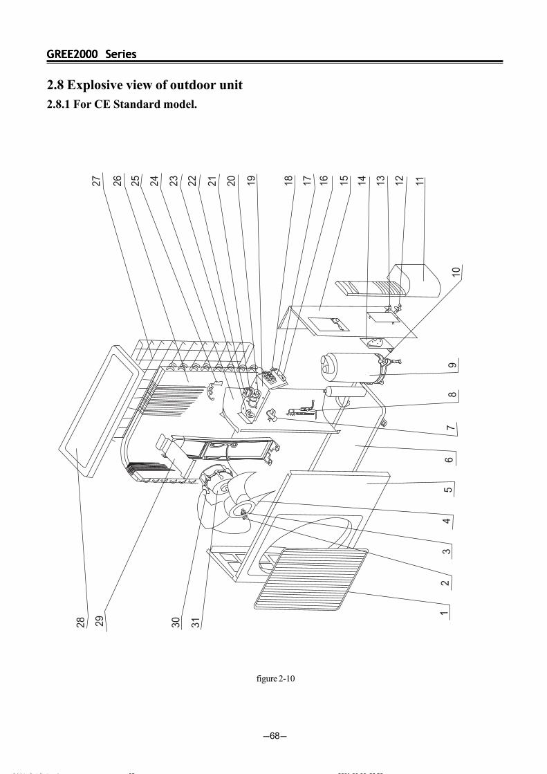
GREE2000 SeriesGREE2000 SeriesGREE2000 SeriesGREE2000 SeriesGREE2000 Series
-68-
2.8 Explosive view of outdoor unit2.8.1 For CE Standard model.
figure 2-10
ÄÚÒ³ Î ¼Û ñ 6 2001-06-06, 23:5868

GREE2000 SeriesGREE2000 SeriesGREE2000 SeriesGREE2000 SeriesGREE2000 Series
-69-
No. DescriptionPart No.
Qty
1 Front Grill 22413431 22413431 22413431 22413431 22413431 22413431 1
2 Nut M6 M6 70310131 70310131 70310131 70310131 70310131 70310131 1
3 Washer 6 6 70410252 70410252 70410252 70410252 70410252 70410252 1
4 Axial Flow Fan 10333412 10333412 10333412 10333412 10333412 10333412 1
5 Front Plate 01533428 01533428 01533428 01533428 01533428 01533428 1
6 Metal Base 01203004 01203004 01203335 01203324 01213045 01213045 1
7 4-way Valve \ 43000301 \ 43000312 \ 43000312 1
8 Capillary Assy 03003402 03003002 03003024 03003170 03003423 03003062 1
9 Compressor SG333DB1 00100121 \ \ \ \ \ 1SG333DB1
9 Compressor SG433EB2 \ 00100123 \ \ \ \ 1SG433EB2
9 Compressor SG533GA1UA \ \ 00100126 \ \ \ 1SG533QA1UA
9 Compressor RH174VHAC \ \ \ 00120078 \ \ 1RH174VHAC
9 Compressor C-RV222H1AA \ \ \ \ 00100340 \ 1C-RV222H1AA
9 Compressor C-RV232BH1AA \ \ \ \ \ 00100339 1C-RV232BH1AA
10 Nut with Washer M8 70310014 70310014 70310014 70310014 70310014 70310014 3
11 Handle 26233021 26233021 26233021 26233021 26233021 26233021 1
12 Valve 3/8" 3/8" 07100143 07100143 07100143 07100143 \ \
12 Valve 1/2" 1/2" \ \ \ \ 07100142 07100142 1
13 Valve 1/4" 1/4" 07100115 07100115 07100115 07100115 07100115 07100115 1
14 Valve Support 01713424 01713424 01713424 01713424 01713424 01713424 1
15 Right Side Plate Assy 01302000 01302000 01302000 01302000 01302000 01302000 1
16 Wire Clamp 71010103 71010103 71010103 71010103 71010103 71010103 2
17 Insulation Gasket D D 70410525 70410525 70410525 70410525 70410525 70410525 1
18 Terminal Board T386A 42011241 42011241 42011241 42011241 42011241 42011241 1
19 Electric Plate 01413425 01413425 01413425 01413425 01413425 01413425 1
20 Comp Capacitor 30uF/450V (30uF/450VAC) 33000021 33000021 33000021 \ 33000021 33000021 1
20 Comp Capacitor 25uF/450V (25uF/450VAC) \ \ \ 33000020 \ \ 1
21 Capacitor clamp 02143401 02143401 02143401 02143401 02143401 02143401 1
22 Fan Capacitor 2.5uF/450V (2.5uF/450VAC) 33010026 33010026 33010026 33010026 33010026 \ 1
22 Fan Capacitor 3uF/450V (3uF/450VAC) \ \ \ \ \ 33010027 1
23 Terminal Board 2-8 2 - 8 \ 42011103 \ 42011103 \ 42011103 1
24 Isolation Sheet Assy 01233417 01233417 01233417 01233417 01233417 01233417 1
25 Tube Sensor \ 39000115 \ 39000115 \ 39000115 1
26 Condenser Assy 01103341 01103202 \ \ \ \ 1
26 Condenser Assy \ \ 01103341 01103052 \ \ 1
26 Condenser Assy \ \ \ \ 01103092 01103203 1
27 Rear grill Assy 11123402 11123402 11123402 11123402 11123402 11123402 1
28 Top cover Assy 01253261 01253261 01253261 01253261 01253261 01253261 1
29 Motor Support 01703391 01703391 01703391 01703391 01703391 01703391 1
30 Self-tapping Screw 10140165 10140165 10140165 10140165 10140165 10140165 4
31 Motor FW25E (FW30A) 15013101 15013101 15013101 15013101 \ \ 1
31 Motor FW30E (FW36A) \ \ \ \ 15013102 15013102 1
KF-
20W/J
KFR-
20W/J
KF-
25W/J
KFR-
25W/J
KF-
35W/J
KFR-
35W/J
2.8.2 Spare parts list of outdoor unit (for CE Stanndard)Table 2-13
The data are subject to change without notice.
ÄÚÒ³ Î ¼Û ñ 6 2001-06-06, 23:5969
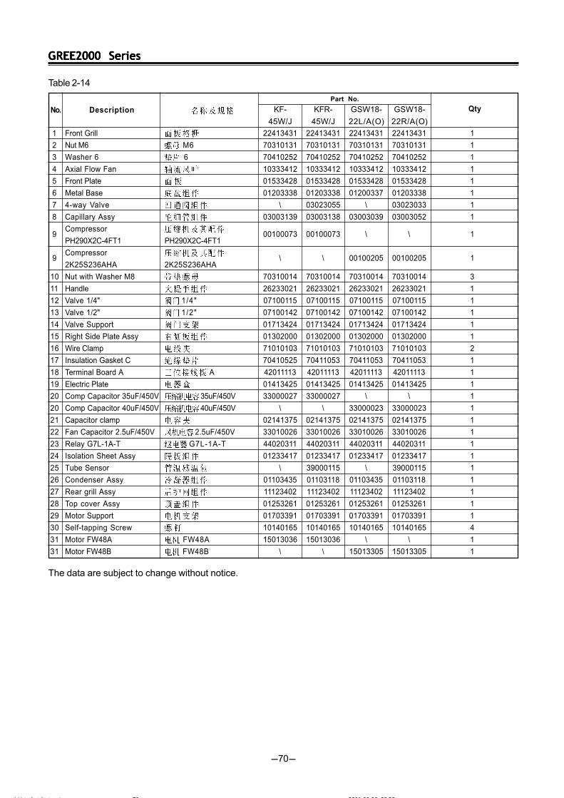
GREE2000 SeriesGREE2000 SeriesGREE2000 SeriesGREE2000 SeriesGREE2000 Series
-70-
KF-
45W/J
KFR-
45W/J
GSW18-
22L/A(O)
GSW18-
22R/A(O)
Description
Part No.
No. Qty
1 Front Grill 22413431 22413431 22413431 22413431 1
2 Nut M6 M6 70310131 70310131 70310131 70310131 1
3 Washer 6 6 70410252 70410252 70410252 70410252 1
4 Axial Flow Fan 10333412 10333412 10333412 10333412 1
5 Front Plate 01533428 01533428 01533428 01533428 1
6 Metal Base 01203338 01203338 01200337 01203338 1
7 4-way Valve \ 03023055 \ 03023033 1
8 Capillary Assy 03003139 03003138 03003039 03003052 1
9Compressor
00100073 00100073 \ \ 1PH290X2C-4FT1 PH290X2C-4FT1
9Compressor
\ \ 00100205 00100205 12K25S236AHA 2K25S236AHA
10 Nut with Washer M8 70310014 70310014 70310014 70310014 3
11 Handle 26233021 26233021 26233021 26233021 1
12 Valve 1/4" 1/4" 07100115 07100115 07100115 07100115 1
13 Valve 1/2" 1/2" 07100142 07100142 07100142 07100142 1
14 Valve Support 01713424 01713424 01713424 01713424 1
15 Right Side Plate Assy 01302000 01302000 01302000 01302000 1
16 Wire Clamp 71010103 71010103 71010103 71010103 2
17 Insulation Gasket C 70410525 70411053 70411053 70411053 1
18 Terminal Board A A 42011113 42011113 42011113 42011113 1
19 Electric Plate 01413425 01413425 01413425 01413425 1
20 Comp Capacitor 35uF/450V 35uF/450V 33000027 33000027 \ \ 1
20 Comp Capacitor 40uF/450V 40uF/450V \ \ 33000023 33000023 1
21 Capacitor clamp 02141375 02141375 02141375 02141375 1
22 Fan Capacitor 2.5uF/450V 2.5uF/450V 33010026 33010026 33010026 33010026 1
23 Relay G7L-1A-T G7L-1A-T 44020311 44020311 44020311 44020311 1
24 Isolation Sheet Assy 01233417 01233417 01233417 01233417 1
25 Tube Sensor \ 39000115 \ 39000115 1
26 Condenser Assy 01103435 01103118 01103435 01103118 1
27 Rear grill Assy 11123402 11123402 11123402 11123402 1
28 Top cover Assy 01253261 01253261 01253261 01253261 1
29 Motor Support 01703391 01703391 01703391 01703391 1
30 Self-tapping Screw 10140165 10140165 10140165 10140165 4
31 Motor FW48A FW48A 15013036 15013036 \ \ 1
31 Motor FW48B FW48B \ \ 15013305 15013305 1
Table 2-14
The data are subject to change without notice.
ÄÚÒ³ Î ¼Û ñ 6 2001-06-06, 23:5970
GREE2000 SeriesGREE2000 SeriesGREE2000 SeriesGREE2000 SeriesGREE2000 Series
-71-
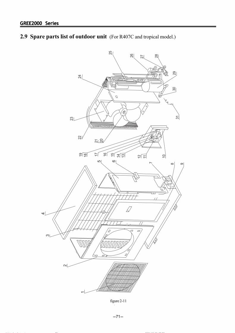
2.9 Spare parts list of outdoor unit (For R407C and tropical model.)
figure 2-11
ÄÚÒ³ Î ¼Û ñ 6 2001-06-06, 23:5971

GREE2000 SeriesGREE2000 SeriesGREE2000 SeriesGREE2000 SeriesGREE2000 Series
-72-
Description QtyKF-
45W/JN
KFR-
45W/JN
KT3FR-45W/J1-
12205
KT3F-
45W/J1
KT3FR-
45W/J1
KT3F-45W/J1-
12205 1 Front Grill 22265250 22265250 22265250 22265250 22265250 22265250 1
2 Front Plate 01433025 01433025 01433031 01433031 01433025 01433025 1
3 Rear grill Assy 01473024 01473024 01473024 01473024 01473024 01473024 1
4 Top cover Assy 01255260 01255260 01255260 01255260 01255260 01255260 1
5 Rear Side Plate 01305001 01305001 01305001 01305001 01305001 01305001 1
6 Handle 26235253 26235253 26235253 26235253 26235253 26235253 1
7 Valve Support 01715256 01715256 01715256 01715256 01715256 01715256 1
8 Metal Base 01203065 01203065 01205010 01205010 01205010 01205010 1
9 Front Side Support 01303019 01303019 01303019 01303019 01303019 01303019 1
10 Electric Plate 20102007 20102007 01415011 01415011 01415011 01415011 1
11 Capacitor clamp 02143442 02143442 02143441 02143441 02143441 02143441 1
12 Comp Capacitor 30uF 30uF 33000021 33000021 \ \ \ \ 1
12 Comp Capacitor 40uF 40uF \ \ 33000023 33000023 \ \ 1
12 Comp Capacitor 35uF 35uF \ \ \ \ 33000027 3300027 1
13 Wire Clamp 71010102 71010102 71010102 71010102 71010102 71010102 2
14 Insulation Gasket D 70410525 70410525 70410525 70410525 70410525 70410525 1
15 Terminal Board T360I \ \ 42010245 42010245 42010245 42010245 1
15 Terminal Board 42011113 42011113 \ \ \ \ 1
16 Fan Capacitor 3uF 3 u F 33010027 33010027 \ \ 33010027 33010021 1
16 Fan Capacitor 2.5uF 2.5uF 33010026 33010026 \ \ 1
17 Start Relay 3ARR3CT24S5 \ 33020201 44020335 44020335 44020335 44020335 13ARR3CT24S5
18 Terminal Board 2-8 2 - 8 \ 42011103 42011103 42011103 42011103 42011103 1
19Capacitor 145-
44020311 44020311 44020311 44020311 44020311 44020311 1174uF/250VAC (G7L-1A-T)
20 Axial Flow Fan 10335254 10335254 10335257 10335257 10335255 10335255 1
21 Motor FW60F FW60F \ \ \ \ 15013250 15013250 1
21 Motor LW80D LW80D \ \ 15015054 15015054 \ \ 1
21 Motor FW60F FW38A 15013032 15013032 \ \ \ \
22 Condenser Assy 01133353 01133354 01103149 01103144 01103142 01103144 1
23 Motor Support 01703027 01703027 01703027 01703027 01703027 01703027 1
24 Isolation Sheet Assy 01233701 01233701 01233022 01233022 01233022 01233022 1
25 4-way Valve STF-0201 \ \ \ 43000313 \ 43000313 1STF-0201
25 4-way Valve V26110B \ 43000305 \ \ \ \ 1V26110B
26 Capillary Assy 03003008 03003009 03003171 03003172 03003007 03003091 1
27 Valve 1/2" 1/2" 07100001 07100001 07103008 07103008 07103008 07103008 1
28 Valve 1/4" 1/4" 07100131 07100131 07100014 07100014 07100014 07100014 1
29Compressor
\ \ \ \ 00100345 00100345 1CI18KQ-PFV-240F CI18KQ-PFV-240F
29Compressor
\ \ 00100016 00100016 \ \ 1CI24KQ-PFZ-240CY C124KQ-PFZ-240CY
29Compressor
00100346 00100346 \ \ \ \ 1C-2RN150H5V C-2RN150H5V
30 Nut with Washer M8 M 8 70310014 70310014 70310014 70310014 70310014 70310014 3
31 Tube Sensor 54SLF \ 39000006 \ 39000006 \ 39000006 1
No.Part No.
2.9.2 Spare parts list of outdoor unit (For R407C and tropical model.)Table 2-15
ÄÚÒ³ Î ¼Û ñ 6 2001-06-06, 23:5972
GREE2000 SeriesGREE2000 SeriesGREE2000 SeriesGREE2000 SeriesGREE2000 Series
-73-
FO
R K
F-2
0GW
/J(2
035M
) LE
D
K
F-2
5GW
/J(2
535M
) L
ED
K
F-3
5GW
/J(3
535M
) L
ED
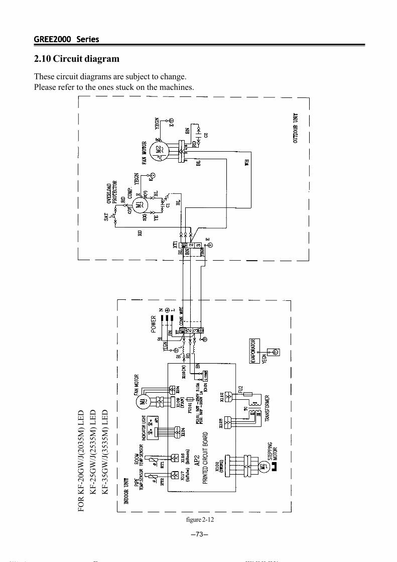
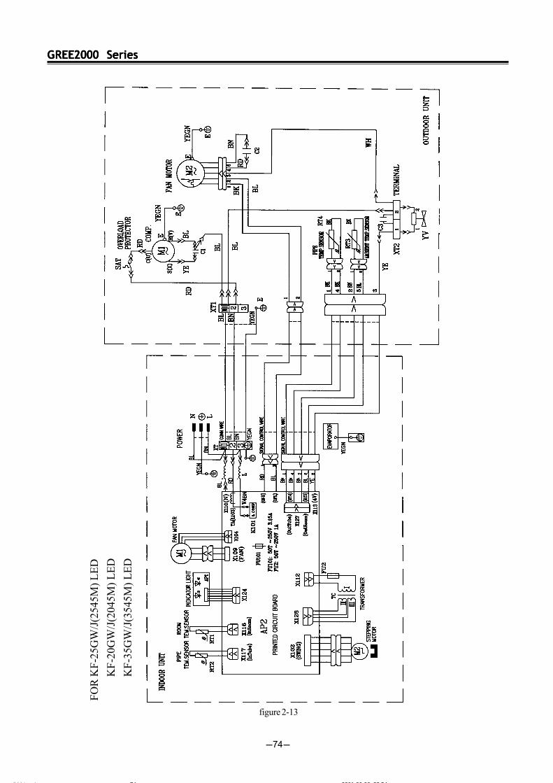
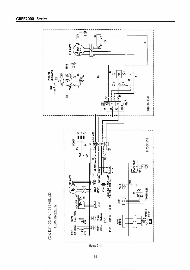
2.10 Circuit diagram
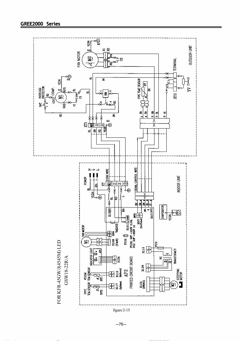
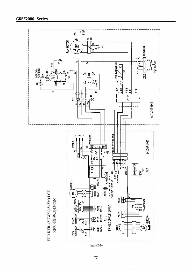
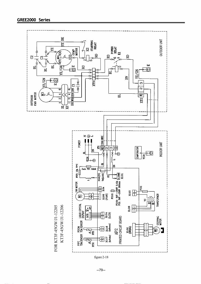
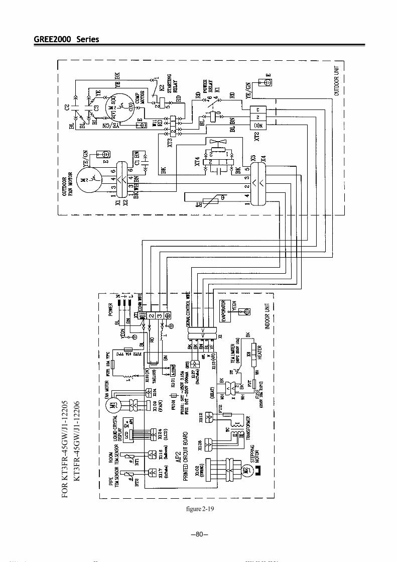
These circuit diagrams are subject to change.Please refer to the ones stuck on the machines.
figure 2-12
ÄÚÒ³ 6 2001-06-06, 23:5473
GREE2000 SeriesGREE2000 SeriesGREE2000 SeriesGREE2000 SeriesGREE2000 Series
-74-
FO
R K
F-2
5GW
/J(2
545M
) LE
D
K
F-2
0GW
/J(2
045M
) L
ED
K
F-3
5GW
/J(3
545M
) L
ED
figure 2-13
ÄÚÒ³ 6 2001-06-06, 23:5474
GREE2000 SeriesGREE2000 SeriesGREE2000 SeriesGREE2000 SeriesGREE2000 Series
-75-
FO
R K
F-4
5GW
/J(4
535M
)LE
D
GSW
18-2
2L/A
figure 2-14
ÄÚÒ³ 6 2001-06-06, 23:5475
GREE2000 SeriesGREE2000 SeriesGREE2000 SeriesGREE2000 SeriesGREE2000 Series
-76-
FOR
KFR
-45G
W/J
(454
5M) L
ED
GS
W18
-22R
/A
figure 2-15
ÄÚÒ³ 6 2001-06-06, 23:5476
GREE2000 SeriesGREE2000 SeriesGREE2000 SeriesGREE2000 SeriesGREE2000 Series
-77-
FO
R K
FR
-45G
W/J
(454
5M) L
CD
KF
R-4
5GW
/J(4
545)
N
figure 2-16
ÄÚÒ³ 6 2001-06-06, 23:5477

GREE2000 SeriesGREE2000 SeriesGREE2000 SeriesGREE2000 SeriesGREE2000 Series
-78-
FO
R K
F-4
5GW
/J(4
535M
) L
CD
K
F-4
5GW
/J(4
535)
N
figure 2-17
ÄÚÒ³ 6 2001-06-06, 23:5478
GREE2000 SeriesGREE2000 SeriesGREE2000 SeriesGREE2000 SeriesGREE2000 Series
-79-
FO
R K
T3F
-45G
W/J
1-12
205
K
T3F
-45G
W/J
1-12
206
figure 2-18
ÄÚÒ³ 6 2001-06-06, 23:5479
GREE2000 SeriesGREE2000 SeriesGREE2000 SeriesGREE2000 SeriesGREE2000 Series
-80-
FO
R K
T3F
R-4
5GW
/J1-
1220
5
KT
3FR
-45G
W/J
1-12
206
figure 2-19
ÄÚÒ³ 6 2001-06-06, 23:5480
GREE2000 SeriesGREE2000 SeriesGREE2000 SeriesGREE2000 SeriesGREE2000 Series
-81-
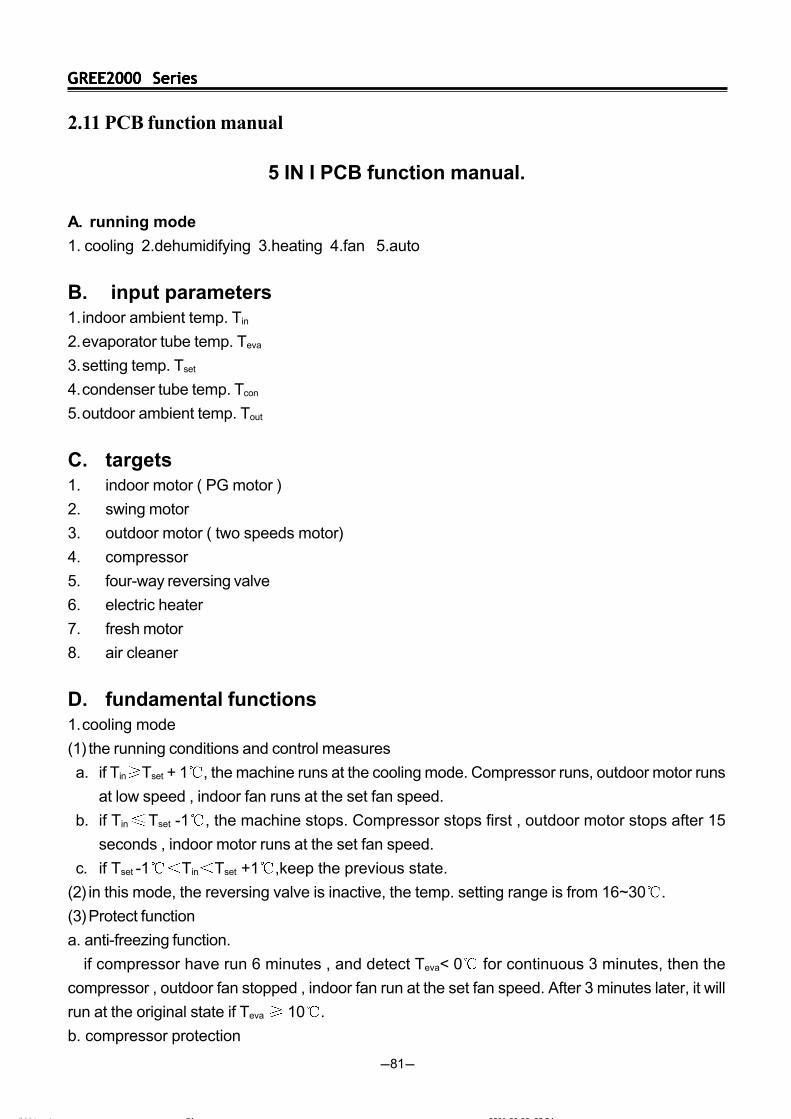
5 IN I PCB function manual.
A. running mode
1. cooling 2.dehumidifying 3.heating 4.fan 5.auto
B. input parameters1.indoor ambient temp. Tin
2.evaporator tube temp. Teva
3.setting temp. Tset
4.condenser tube temp. Tcon
5.outdoor ambient temp. Tout
C. targets1. indoor motor ( PG motor )
2. swing motor
3. outdoor motor ( two speeds motor)
4. compressor
5. four-way reversing valve
6. electric heater
7. fresh motor
8. air cleaner
D. fundamental functions1.cooling mode
(1) the running conditions and control measures
a. if Tin Tset + 1 , the machine runs at the cooling mode. Compressor runs, outdoor motor runs
at low speed , indoor fan runs at the set fan speed.
b. if Tin Tset -1 , the machine stops. Compressor stops first , outdoor motor stops after 15
seconds , indoor motor runs at the set fan speed.
c. if Tset -1 Tin Tset +1 ,keep the previous state.
(2) in this mode, the reversing valve is inactive, the temp. setting range is from 16~30 .
(3)Protect function
a. anti-freezing function.
if compressor have run 6 minutes , and detect Teva< 0 for continuous 3 minutes, then the
compressor , outdoor fan stopped , indoor fan run at the set fan speed. After 3 minutes later, it will
run at the original state if Teva 10 .
b. compressor protection
2.11 PCB function manual
ÄÚÒ³ 6 2001-06-06, 23:5481
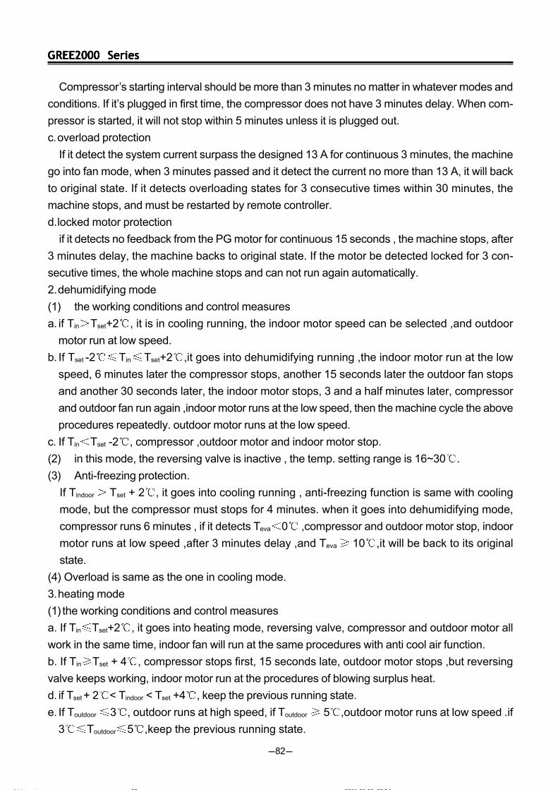
GREE2000 SeriesGREE2000 SeriesGREE2000 SeriesGREE2000 SeriesGREE2000 Series
-82-
Compressor’s starting interval should be more than 3 minutes no matter in whatever modes and
conditions. If it’s plugged in first time, the compressor does not have 3 minutes delay. When com-
pressor is started, it will not stop within 5 minutes unless it is plugged out.
c.overload protection
If it detect the system current surpass the designed 13 A for continuous 3 minutes, the machine
go into fan mode, when 3 minutes passed and it detect the current no more than 13 A, it will back
to original state. If it detects overloading states for 3 consecutive times within 30 minutes, the
machine stops, and must be restarted by remote controller.
d.locked motor protection
if it detects no feedback from the PG motor for continuous 15 seconds , the machine stops, after
3 minutes delay, the machine backs to original state. If the motor be detected locked for 3 con-
secutive times, the whole machine stops and can not run again automatically.
2.dehumidifying mode
(1) the working conditions and control measures
a. if Tin Tset+2 , it is in cooling running, the indoor motor speed can be selected ,and outdoor
motor run at low speed.
b. If Tset -2 Tin Tset+2 ,it goes into dehumidifying running ,the indoor motor run at the low
speed, 6 minutes later the compressor stops, another 15 seconds later the outdoor fan stops
and another 30 seconds later, the indoor motor stops, 3 and a half minutes later, compressor
and outdoor fan run again ,indoor motor runs at the low speed, then the machine cycle the above
procedures repeatedly. outdoor motor runs at the low speed.
c. If Tin Tset -2 , compressor ,outdoor motor and indoor motor stop.
(2) in this mode, the reversing valve is inactive , the temp. setting range is 16~30 .
(3) Anti-freezing protection.
If Tindoor Tset + 2 , it goes into cooling running , anti-freezing function is same with cooling
mode, but the compressor must stops for 4 minutes. when it goes into dehumidifying mode,
compressor runs 6 minutes , if it detects Teva 0 ,compressor and outdoor motor stop, indoor
motor runs at low speed ,after 3 minutes delay ,and Teva 10 ,it will be back to its original
state.
(4) Overload is same as the one in cooling mode.
3.heating mode
(1) the working conditions and control measures
a. If Tin Tset+2 , it goes into heating mode, reversing valve, compressor and outdoor motor all
work in the same time, indoor fan will run at the same procedures with anti cool air function.
b. If Tin Tset + 4 , compressor stops first, 15 seconds late, outdoor motor stops ,but reversing
valve keeps working, indoor motor run at the procedures of blowing surplus heat.
d. if Tset + 2 < Tindoor
< Tset +4 , keep the previous running state.
e. If Toutdoor 3 , outdoor runs at high speed, if Toutdoor 5 ,outdoor motor runs at low speed .if
3 Toutdoor 5 ,keep the previous running state.
ÄÚÒ³ 6 2001-06-06, 23:5482
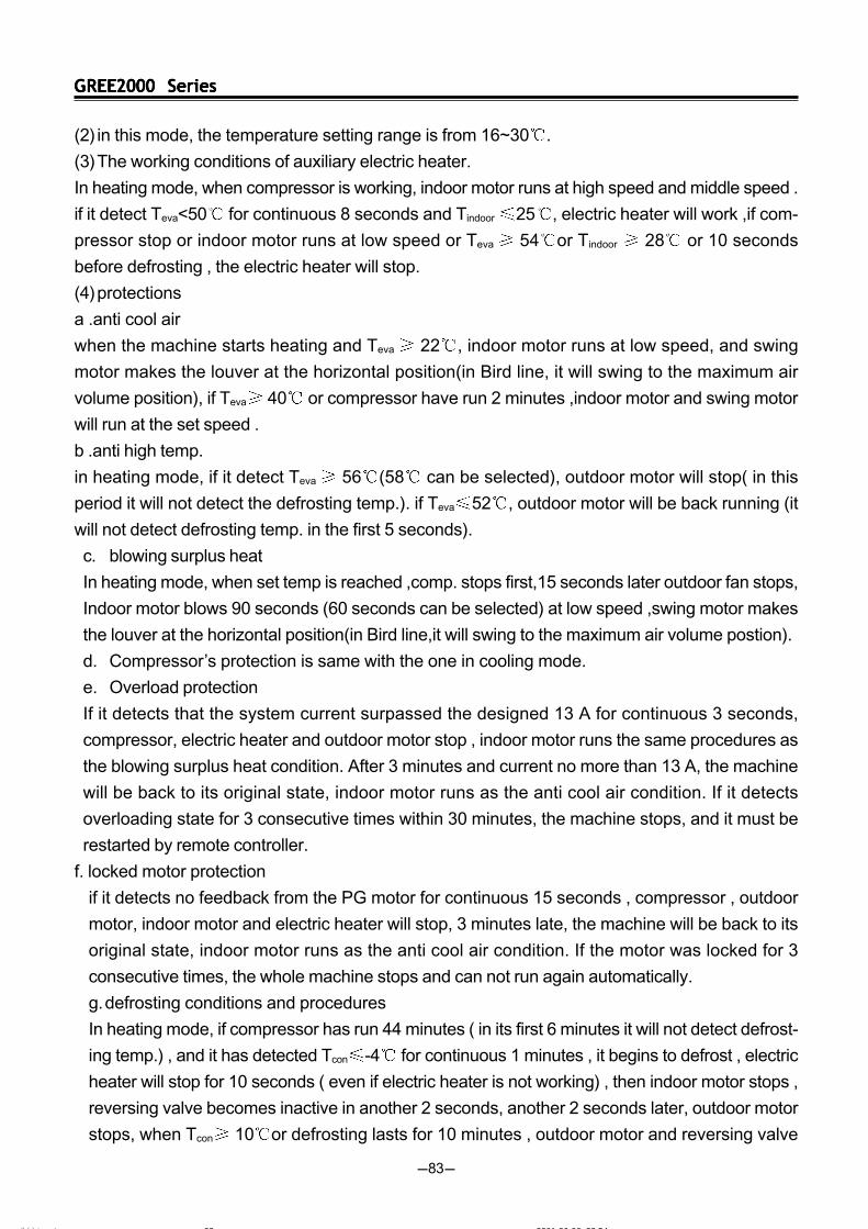
GREE2000 SeriesGREE2000 SeriesGREE2000 SeriesGREE2000 SeriesGREE2000 Series
-83-
(2) in this mode, the temperature setting range is from 16~30 .
(3)The working conditions of auxiliary electric heater.
In heating mode, when compressor is working, indoor motor runs at high speed and middle speed .
if it detect Teva<50 for continuous 8 seconds and Tindoor 25 , electric heater will work ,if com-
pressor stop or indoor motor runs at low speed or Teva 54 or Tindoor 28 or 10 seconds
before defrosting , the electric heater will stop.
(4)protections
a .anti cool air
when the machine starts heating and Teva 22 , indoor motor runs at low speed, and swing
motor makes the louver at the horizontal position(in Bird line, it will swing to the maximum air
volume position), if Teva 40 or compressor have run 2 minutes ,indoor motor and swing motor
will run at the set speed .
b .anti high temp.
in heating mode, if it detect Teva 56 (58 can be selected), outdoor motor will stop( in this
period it will not detect the defrosting temp.). if Teva 52 , outdoor motor will be back running (it
will not detect defrosting temp. in the first 5 seconds).
c. blowing surplus heat
In heating mode, when set temp is reached ,comp. stops first,15 seconds later outdoor fan stops,
Indoor motor blows 90 seconds (60 seconds can be selected) at low speed ,swing motor makes
the louver at the horizontal position(in Bird line,it will swing to the maximum air volume postion).
d. Compressor’s protection is same with the one in cooling mode.
e. Overload protection
If it detects that the system current surpassed the designed 13 A for continuous 3 seconds,
compressor, electric heater and outdoor motor stop , indoor motor runs the same procedures as
the blowing surplus heat condition. After 3 minutes and current no more than 13 A, the machine
will be back to its original state, indoor motor runs as the anti cool air condition. If it detects
overloading state for 3 consecutive times within 30 minutes, the machine stops, and it must be
restarted by remote controller.
f. locked motor protection
if it detects no feedback from the PG motor for continuous 15 seconds , compressor , outdoor
motor, indoor motor and electric heater will stop, 3 minutes late, the machine will be back to its
original state, indoor motor runs as the anti cool air condition. If the motor was locked for 3
consecutive times, the whole machine stops and can not run again automatically.
g.defrosting conditions and procedures
In heating mode, if compressor has run 44 minutes ( in its first 6 minutes it will not detect defrost-
ing temp.) , and it has detected Tcon -4 for continuous 1 minutes , it begins to defrost , electric
heater will stop for 10 seconds ( even if electric heater is not working) , then indoor motor stops ,
reversing valve becomes inactive in another 2 seconds, another 2 seconds later, outdoor motor
stops, when Tcon 10 or defrosting lasts for 10 minutes , outdoor motor and reversing valve
ÄÚÒ³ 6 2001-06-06, 23:5483
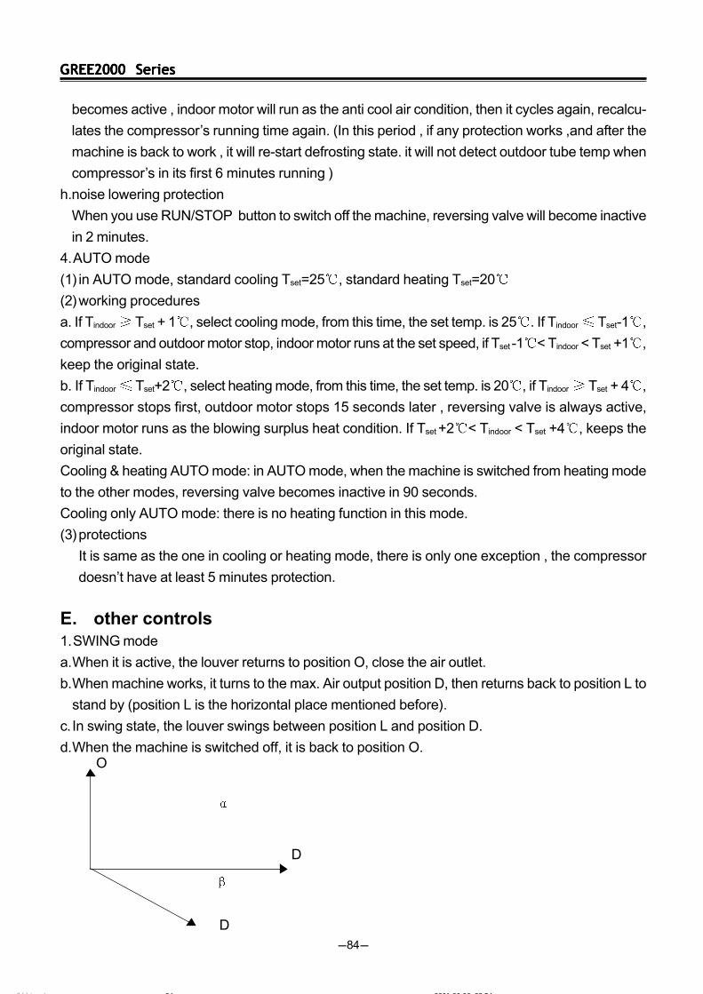
GREE2000 SeriesGREE2000 SeriesGREE2000 SeriesGREE2000 SeriesGREE2000 Series
-84-
becomes active , indoor motor will run as the anti cool air condition, then it cycles again, recalcu-
lates the compressor’s running time again. (In this period , if any protection works ,and after the
machine is back to work , it will re-start defrosting state. it will not detect outdoor tube temp when
compressor’s in its first 6 minutes running )
h.noise lowering protection
When you use RUN/STOP button to switch off the machine, reversing valve will become inactive
in 2 minutes.
4.AUTO mode
(1) in AUTO mode, standard cooling Tset=25 , standard heating Tset=20
(2)working procedures
a. If Tindoor Tset + 1 , select cooling mode, from this time, the set temp. is 25 . If Tindoor Tset-1 ,
compressor and outdoor motor stop, indoor motor runs at the set speed, if Tset -1 < Tindoor < Tset
+1 ,
keep the original state.
b. If Tindoor Tset+2 , select heating mode, from this time, the set temp. is 20 , if Tindoor Tset + 4 ,
compressor stops first, outdoor motor stops 15 seconds later , reversing valve is always active,
indoor motor runs as the blowing surplus heat condition. If Tset +2 < Tindoor < Tset +4 , keeps the
original state.
Cooling & heating AUTO mode: in AUTO mode, when the machine is switched from heating mode
to the other modes, reversing valve becomes inactive in 90 seconds.
Cooling only AUTO mode: there is no heating function in this mode.
(3)protections
It is same as the one in cooling or heating mode, there is only one exception , the compressor
doesn’t have at least 5 minutes protection.
E. other controls1.SWING mode
a.When it is active, the louver returns to position O, close the air outlet.
b.When machine works, it turns to the max. Air output position D, then returns back to position L to
stand by (position L is the horizontal place mentioned before).
c. In swing state, the louver swings between position L and position D.
d.When the machine is switched off, it is back to position O.
O
D
O
D
D
ÄÚÒ³ 6 2001-06-06, 23:5484
GREE2000 SeriesGREE2000 SeriesGREE2000 SeriesGREE2000 SeriesGREE2000 Series
-85-
D
In Gree 2000 line and new 24000BTU line , =93, =45
In Bird line, =80, =25
Attention : in Bird line, the louver will stop at position D . in other lines, the louver will stop at position
L)
Bird line:
a.When it is active, the louver returns to position O, close the air outlet.
b.When machine works, it turns 80 degrees to the max. Air output position D and stands by.
c. In swing state, the louver swings between position L(25) and position D.
d.When the machine is switched off, it is back to position O.
2.beeper
a.When PCB becomes active or receives the signal from the remote controller , the beeper will
beep.
b.If thermostat is open-circuited or short-circuited, when you press the TEST button, the beeper will
alarm at the frequency 2HZ.
3.indication lamps
it flashes when defrosting begin.
4.multi-step switch .
a. If the switch is in AUTO position, the machine will run at the AUTO mode, if there is a signal from
remote controller, it will run according to the signal .
b. If the switch is in TEST position, the machine will run at the COOL mode, indoor motor will run at
high speed , swing motor will run according to SWING mode. If there is a signal from remote
controller, it will run according to the signal .if the thermostat is open-circuited or short-circuited ,
the beeper will alarm at the frequency 2 HZ .
c. If the switch is in RUN position , the machine will run according to the remote signal.
d. If the switch is in STOP position, the machine will stop.
5.SLEEP mode.
a.In cooling or dehumidifying mode, 1 hour after you set the sleep timer ,Tset will add 1 automatically,
another 1 hour, another 1 will be added.
b.In heating mode, 1 hour after you set the sleep timer, Tset will lower 1 automatically, another 1
hour, another 1 will be lowered .
6.Automatic fan speed .
a.In cooling mode, if Tindoor > Tset + 4 high speed
Tset +2 Tindoor Tset +4 middle speed
Tindoor < Tset + 2 low speed
b.b. In heating mode, if Tindoor Tset - 1 high speed
ÄÚÒ³ 6 2001-06-06, 23:5485
GREE2000 SeriesGREE2000 SeriesGREE2000 SeriesGREE2000 SeriesGREE2000 Series
-86-
Tset -1 < Tindoor <Tset +1 middle speed
Tindoor Tset + 2 low speed
F. Fresh air function.
1.there are two fresh air modes .
a.fresh air 2
fresh air motor will work 1 hour, then rest 1 hour, then cycle again.
b.fresh air 1
press the button AIR on the remote controller to select fresh air 1 function, the swing motor keeps
running till you give a signal to change it.
G.air cleaning
In air cleaning mode, air cleaner works while indoor fan runs and air cleaner stops while indoor
fan stops.
The speeds of the wind of all types of the air-conditioner are as below:
000: 900,850, 800, 700 (RPM);
001: 1000, 900, 850, 700(RPM);
010: 1050, 950, 900, 700(RPM);
011: 1100, 1000, 950, 700(RPM);
100: 1200, 1100, 1000, 700(RPM);
101: 1250, 1100, 1050, 700(RPM);
111: 1400, 1200, 1100, 700(RPM);
ÄÚÒ³ 6 2001-06-06, 23:5486


![GLSV-035 series - MPL Power · GLSV - 035 B xxx Series name Rated Output Power [W] Option name 012 – rated output voltage is 12V 024 – rated output voltage is 24V 036 – rated](https://img.pdfslide.net/doc/110x75/5ebc32ca3243bb12635f5334/glsv-035-series-mpl-power-glsv-035-b-xxx-series-name-rated-output-power-w.jpg)

![BFK 470 spring-applied brake212.113.105.12/library/INTORQ/INTORQ_BFK470_2_370Nm_en_0... · INTORQ 155-1 E318895 Armature plate List of abbreviations PN [W] Rated coil power at rated](https://img.pdfslide.net/doc/110x75/61331667dfd10f4dd73adcbf/bfk-470-spring-applied-brake21211310512libraryintorqintorqbfk4702370nmen0.jpg)