Embed Size (px)
Citation preview

Hanbo Tao 2x2 Dipole Antenna Array
1
San Jose State University
EE 172 - Microwave
2x2 Dipole Antenna Array
Dr. Ray Kwok
by Hanbo Tao
May 25th, 2011

Hanbo Tao 2x2 Dipole Antenna Array
2
Abstract
This report will explain the theory of dipole antenna, and a 2x2 half wave dipole antenna will be
designed at 2.4 GHz frequency. The antenna will also be built, and it has three main parts: four half wave
dipole antennas, four baluns, and one power divider. I would simulate my design with the software,
which’s called 4nec2. In addition, I would test my antenna in the laboratory. The return loss would be
measured, and I would also measure its radiation pattern and its dB gain by comparing with the
standard 10dB gain antenna from the Dr. Kwok. I would also test the power combiner. In the end, the
simulated gain is 9.08 dB, and the measured gain is 8dB.
Introduction
According to the article from Electronics and Radio Today, dipole antenna consists of two equal
length poles, and the power is applied to the center feeder as shown in the Figure 1. It is a very basic
construction of a single dipole antenna, and the power transfers to or receives from the antenna
through the feeder. In this report, I would build an ideal dipole antenna, which is same to the half wave
dipole antenna shown in the Figure 2. Moreover, to get the maximum power that is transferred
between the feeder and the antenna, the impedance of the antenna and the feeder has to be matched;
in this case, the impedance is 50 Ω.
Figure 1. Basic Construction of a Dipole Antenna Figure 2. Half-wave Dipole Antenna
As we can see on the Figure 2, the total length of the dipole is a half wavelength, so it is half the
length of the original dipole antenna shown in the Figure 1, this makes each section the dipole a quarter
wavelength long in the Figure 2.

Hanbo Tao 2x2 Dipole Antenna Array
3
Figure 3. Radiation Pattern of a Dipole
Next, let’s look at the Figure 3 ("RADIATION PATTERN OF A DIPOLE"), the radiation pattern of a
dipole. We can see clearly the 3D radiation pattern and its horizontal and vertical pattern in the Figure 3.
When we look at the vertical pattern, we can see that direction of maximum radiation is at right angles
to the axis of the antenna, which are 90 and 270 degrees in this case.
Theory and Procedure
The design of the 2x2 half wave dipole antennas is shown in the Figure 4 below:
Materials needed:
50 Ω coax cable(RG58A) with BNC connector
BNC flat mounts
22 AWG wire
Solder wires
Copper sheet
Brass shim stock sheet
BNC female connector to female N type connector
#4 screws
Sufficient tools (drills, tapes, solder iron, clamps, knife, third hand, and others)
Figure 4. 2x2 Half-wave Dipole Antenna

Hanbo Tao 2x2 Dipole Antenna Array
4
As I mentioned previous, the requirement for this antenna is to be operated at 2.4GHz, so I used
the following equation to calculate the length of the wire.
Length of the half wave dipole:
Length of the quarter wave dipole:
The factor A in the above equation is the ratio of the length of the antenna to the thickness of
the wire or tube used as the element. The Figure 5 shows the results of the ratio of the length and
thickness ("Electronics and Radio Today").
Figure 5. Factor A
I would also need to use balun to get the maximum power that is transferred between the
feeder and the antenna. In the Figure 6 ("Antenna-Theory.com"), the pink line is the inner conductor of
the coax cable, grey is the outer conductor, red line is the antenna wire, and the green is the balun. We
want to make the current ID travels in the opposite direction to the current IC; therefore, the voltage on
the inner conductor is out of phase with the voltage on the outer conductor are equal in magnitude,
then the currents will cancel in the region below the balun. The balanced operation is restored.
Figure 6. Current Flow
Hanbo Tao 2x2 Dipole Antenna Array
5
The equation is shown below calculate the length of the balun for 2.4GHz half wave dipole
antenna:
Length of balun:
The velocity factor in the above equation for the coax cable RG-58A is 0.68, and according to
Wikipedia, “The velocity factor (VF),[1] also called wave propagation speed or velocity of propagation
(VoP or vP),[2] of a transmission medium is the speed at which a wavefront passes through the medium,
relative to the speed of light. For optical signals, refractive index is a similar quantity.” ("Wave
propagation speed")
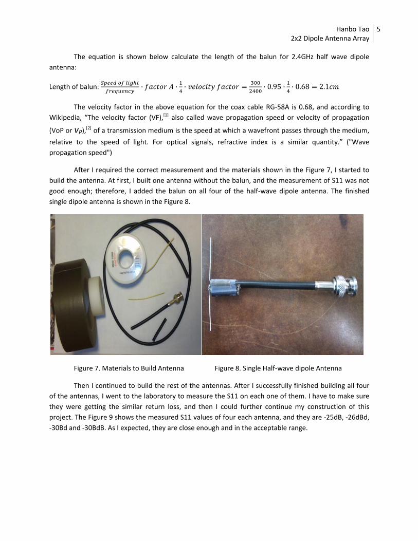
After I required the correct measurement and the materials shown in the Figure 7, I started to
build the antenna. At first, I built one antenna without the balun, and the measurement of S11 was not
good enough; therefore, I added the balun on all four of the half-wave dipole antenna. The finished
single dipole antenna is shown in the Figure 8.
Figure 7. Materials to Build Antenna Figure 8. Single Half-wave dipole Antenna
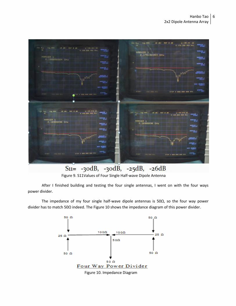
Then I continued to build the rest of the antennas. After I successfully finished building all four
of the antennas, I went to the laboratory to measure the S11 on each one of them. I have to make sure
they were getting the similar return loss, and then I could further continue my construction of this
project. The Figure 9 shows the measured S11 values of four each antenna, and they are -25dB, -26dBd,
-30Bd and -30BdB. As I expected, they are close enough and in the acceptable range.
Hanbo Tao 2x2 Dipole Antenna Array
6
Figure 9. S11Values of Four Single Half-wave Dipole Antenna
After I finished building and testing the four single antennas, I went on with the four ways
power divider.
The impedance of my four single half-wave dipole antennas is 50Ω, so the four way power
divider has to match 50Ω indeed. The Figure 10 shows the impedance diagram of this power divider.
Figure 10. Impedance Diagram

Hanbo Tao 2x2 Dipole Antenna Array
7
As we see in the Figure 10 (Whitsel), the 50Ω//50Ω=25Ω on the two sides of the WR 90
waveguide, and I used the equation below to get the impedance in the middle port.
Z0 = (Z1* Z2)^1/2, Where Z1=Input Impedance, Z2=Output Impedance
Z0= (25*100)^1/2 = 50Ω
The dimensions of the WR-90 waveguide: Width=0.90“, and Height=0.40".
The dimensions of the center conductor piece for 2.4 GHz and 50 Ω: width= 0.490 “, thickness=0.031 ",
½ wavelength= 2.56 ", and ¼ wavelength=1.28 “.
Figure 11. Dimensions of WR-90 Waveguide and Center Conductor
The complete design of the power divider is shown in the Figure 12 (Whitsel) below.
Figure 12. Four Ways Power Divider
According to the Mr. Whitsel, “The presence of the sides of the waveguide do not effect the
results because of the distance from the center conductor.” Therefore, I left the two sides of the
waveguide open.
After finished the design the four ways power divider, I bought the copper sheet, brass shim
stock sheet, and five BNC mounts. The Figure 13 is the metal sheets that cut into desired size, and Figure
14 is the finished WR-90 waveguide with drilled holes, amounts and center conductor.

Hanbo Tao 2x2 Dipole Antenna Array
8
Figure 13. Metal sheet Figure 14. Parts are ready to assemble
I drilled additional ten screw holes on the copper waveguide, I mounted the top there BNC
mounts on the waveguide at first shown in the Figure 15. Then, I used solder iron to solder the center
conductor piece on the three probes of the BNC mounts. After completed this step, I mounted the
bottom two BNC mounts, and solder the two probes onto the center conductor piece. The figure 16
shows the side view of the completed power divider. As shown on the both figures, there is a gap on the
waveguide. I tried to use the solder iron to seal the gap, but it was not hot enough; therefore, I had a
very hard time to close the gap. In the end, I used the duck tape and the clamp to close the gap, but it
was not perfect in this way; however, the power divider still worked and gave acceptable results.
Figure 15. Front View of the Power Divider Figure 16. Side View of the Power Divider

Hanbo Tao 2x2 Dipole Antenna Array
9
After I successfully built the four ways power divider, I need to test the it; thus, I measured all
the five ports, one at a time, with antenna connected to the other ports as suggested by the Dr. Kwok.
The Figure 17, Figure 18, Figure 19, Figure 20, and Figure 21 show the connection of the
antennas to the desired ports in order to test the all the five ports of the power divider; in addition, the
measured S11 are also shown on the right. By the way, the Figure 21 is the setup for the originally
designed 2x2 half-wave antenna. I would use the connection shown in the Figure 21 to do the radiation
pattern and dB gain measurements for the rest of the report.
Figure 17. Testing Port 1, and S11 is -44dB
Figure 18. Testing Port 2, and S11 is -39dB

Hanbo Tao 2x2 Dipole Antenna Array
10
Figure 19. Testing Port 3, and S11 is -34dB
Figure 20. Testing Port 4, and S11 is -38dB
Figure 21. Testing Port 5, and S11 is -40dB
Look through Figure 17 to Figure 21, the S11 measurements on all five ports are: -44dB, -39dB,

Hanbo Tao 2x2 Dipole Antenna Array
11
-34dB, -38dB, and -40dB. These results shows that the power divider is working fine. Even though the
return lose are not exactly same, they are still in a very close range. In fact, there are several causes for
the error, such as the measurement’s environment where there are a lot of noise or things that would
constantly changing the value of the S11; moreover, the power divider is fully handmade, I am sure
there are few errors during the construction due to the lack of the construction skills and sufficient tools.
Simulation
I used the software 4nec2 to simulate the 2x2 half-wave dipole antenna. This software is easier
to use compare the microwave office, and it gives the 3D radiation pattern of the antenna which the
microwave office is incapable of.
However, the 4nec2 does not generate the circuit of the antenna, so I used the microwave office
to show the equivalent circuit of this project. The Figure 22 is the equivalent circuit for 2x2 half-wave
antenna.
Figure 22. Equivalent Circuit for 2x2 Half-wave Dipole Antenna
Look at the Figure 22, the very left port works as the port to the four ways power divider which
is the two way power divider; and it separate into another two path connect to the other two way
power divider. Finally, the four single half-wave dipole antennas connect at the end of the four
connections of these power dividers.

Hanbo Tao 2x2 Dipole Antenna Array
12
Now let’s move on to the 4nec2 simulation. At first, I swept the frequency range from the 1 GHz
to 4 GHz , so I got the waves of SWR and return loss which’s shown in the Figure 23 below. The return
loss around the 2.4 GHz is about -34dB.
Figure 23. SWR and Return Loss
Then I generated the far field patter, and I got the 2D radiation pattern in both vertical and
horizontal planes which are shown in the Figures below.
Figure 24. Vertical Plane Radiation Pattern Figure 25. Horizontal Plane Radiation Pattern

Hanbo Tao 2x2 Dipole Antenna Array
13
If the 2D patterns are not clear enough for you, I also have the 3D radiation pattern shown in
the Figure 26 below. By the way, the length from the top antenna to the bottom antenna is exactly two
λ, so the pattern is not as interesting as I thought. However, it is very clear to see the max gain with the
different colors on the graph.
Figure 26. Side View of the Radiation Pattern Figure 27. Another Angle of the Radiation Pattern
From the Figure above, we see the max gain appears at the vertical angles to the x axis, and it is
about 9.08 dB.
Results
After completed the construction of the antenna and simulation, I moved on the test it. As I
mentioned before, I use the design in the Figure 21 above to do all the test and measurements.
For this part of the test, I would do five measurements:
1. Measure the vertical plane radiation pattern at 1st location
2. Re-measure the vertical plane radiation pattern at 2nd
location
3. Measure the horizontal plane radiation pattern at 1st location
4. Re-measure the horizontal plane radiation pattern at 2nd
location
5. Measure the S12 of my antenna and standard antenna from Dr. Kwok, and
compare the difference in dB to get the actual gain of my designed antenna
Thus, I started to measure the vertical plane radiation pattern; I used the Phil’s 2x2 bow tie antenna as the reference antenna because it operates in the same frequency, which is 2.4 GHz. I
Hanbo Tao 2x2 Dipole Antenna Array
14
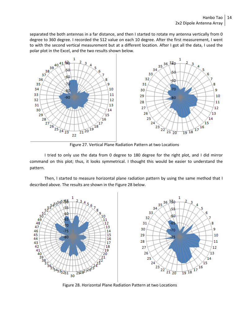
separated the both antennas in a far distance, and then I started to rotate my antenna vertically from 0 degree to 360 degree. I recorded the S12 value on each 10 degree. After the first measurement, I went to with the second vertical measurement but at a different location. After I got all the data, I used the polar plot in the Excel, and the two results shown below.
Figure 27. Vertical Plane Radiation Pattern at two Locations
I tried to only use the data from 0 degree to 180 degree for the right plot, and I did mirror
command on this plot; thus, it looks symmetrical. I thought this would be easier to understand the
pattern.
Then, I started to measure horizontal plane radiation pattern by using the same method that I
described above. The results are shown in the Figure 28 below.
Figure 28. Horizontal Plane Radiation Pattern at two Locations

Hanbo Tao 2x2 Dipole Antenna Array
15
Compare the both Figure 27 and Figure 28 to the simulated radiation patterns; they are not
exactly the same. The reasons for these differences are caused by the measurement’s environment.
There were a lot of metals, testing machines and computers in the laboratory; thus, there are great
amount of the reflection from the walls and the other electronic devices in the room. I am sure if we can
get the specific room (showed on the Dr. Kwok’s lecture slides) which’s constructed to measure the
antenna, there will be a better result, and the measured radiation patterns will be similar to the
simulated ones.
Next, I would do the last measurement that described above, which is to measure the S12 of my
antenna and standard antenna from Dr. Kwok, and compare the difference in dB to get the actual gain
of my designed antenna. The standard antenna is shown in the Figure 29 below, it has a gain of 10dB.
Figure 29. Standard Antenna with Gain of 10dB
In this measurement, I still used the Phil’s 2x2 bow tie antenna as the reference antenna. At first,
I measured S12 of my antenna, which’s -62dB. Then I replaced my antenna with Dr. Kwok’s standard
antenna at the same spot, and measured its S12 again, which’s -60dB. After the two measurements, I
used the equation form the Dr. Kwok’s lecture slides to calculate the actual gain of my antenna.
S21(standard) = -60 dB (with respect to source)
S21(test) = - 62 dB (for antenna under test)
G(ant) = G(standard) - S21(standard) + S21(ant)
2x2 half wave dipole antenna: G(ant) = 10dB – (-60dB) + (-62dB) = 8 dB
Therefore, my designed 2x2 half-wave dipole antenna has gain of 8dB, which is 2dB smaller than
the standard antenna. In addition, the max gain from the simulation is 9.08dB and the max gain from the
measurement is 8dB; thus, the difference between the simulated gain and actual gain is only 1.08dB.

Hanbo Tao 2x2 Dipole Antenna Array
16
Discussion
The project was successfully completed. At first, I built the four single half-wave dipole antennas
with balun attached to each of them, and tested all of them. Then I continued to build the four ways
power divider, and tested all five ports. Finally I assembled four single antennas with the power divider,
and the actual gain of the 2x2 half-wave dipole antenna is 8dB.
I am happy with the results, but there are still many improvements that could have been done
to make results better. I will try to get a torch and actually seal the small gap on the waveguide, and I
will also try to find a different way to mount the BNC mounts on the waveguide rather the using the
screws. I think this will give better return lose and the overall gain of the antenna.
I wish that we may have a specific antenna measurement room in the future, so there would be
less reflection from the other entire source. In this way, the measurements of the vertical and horizontal
radiation patterns would be more accurate.

Hanbo Tao 2x2 Dipole Antenna Array
17
References:
"Dipole antenna." Electronics and Radio Today n. pag. Web. 27 May 2011. <http://www.electronics-
radio.com/articles/radio/antennas/dipole/dipole-antenna.php>.
"Folded Baluns." Antenna-Theory.com. N.p., n.d. Web. 25 May 2011. <http://www.antenna-
theory.com/definitions/foldedbalun.php>.
"Half-Wave Dipole Aerial & Making a Balun." NRG Kits. N.p., n.d. Web. 25 May 2011.
<http://nrgkits.shopfactory.com/workshop/half_wave_dipole_aerial.htm>.
"RADIATION PATTERN OF A DIPOLE." RADIATION PATTERN OF A DIPOLE. Web. 27 May 2011.
<http://www.tpub.com/content/neets/14182/css/14182_186.htm>.
"Wave propagation speed." Wikimedia Foundation, Inc, 6 April 2011. Web.
<http://en.wikipedia.org/wiki/Wave_propagation_speed>.
Whitsel, Ron J. "Stripline Power Dividers Using Waveguide ." ARRL Affiliated Amateur Radio Club . Mt.
Airy VHF Radio Club, n.d. Web. 25 May 2011. <http://www.packratvhf.com/article4.htm>.