Embed Size (px)
Citation preview

3-5 Day Special Delivery Call for Pricing & Details
www.btahellerinc.com

Deepholedrillingwasfirstdevelopedforthemanufacturingoffirearms,hence the name gundrilling.Originally a time-consuming and expensiveprocess,technologicaladvanceshavemadeitahighlyefficientmanufacturingprocessutilizedinallmetalcuttingindustries,includingautomotive,aircraft,aerospace, construction,medical, tool anddie, petro chemical, hydraulics,pneumaticsandmore. Gundrillingisanidealsolutionformostdeepholeandhighprecisiondrillingprojects.This operationproduces accurate, repeatableholeswith excellentsurfacefinishes.Gundrills hold location to precise tolerances, are sized toexactspecifications,produceburr-freeholesandcanbeformedtoproducespecificshapesinblindholesandbottomformingwithaminimumofmachineadaptation.These systems can be easily integratedwithCNCmachiningcenters,lathesandmillingmachinesforarelativelysmallinvestment,makingitaffordableforlargeorsmallshopswithproductionrequirementsvaryingfromonepiecetohundredsofthousands.
The gundrill’s function Gundrillingisametalremovalprocessinvolvingadrillingmachine,ahighpressurecoolantsystemandahighqualitydrillwithasingleordoubleflutealongtheshank.Inoperation,thedrillispositionedandheldinthespindlenose,thenguidedintotheworkpiecethroughaprestartedholeorguidebushingtopreventvibrationandensureaccuracy.Thedrilltip’scuttingedgesproducethincurledchipsthatarecarriedbackalongtheshankbythehighpressurecoolantanddepositedinthechipbox.Theoff-centerdesignofthecuttingedgescreatespressurewithinthebore,whichiscarriedbypadsbehindthedrilltip.Thecoolantthatflushesoutthechipsalsolubricatesthesepads,whichburnishthesurfaceanddevelopthefinefinishforwhichgundrillingisknown.
The gundrilling machine Designed to provide optimum conditions for gundrill operation, thegundrillingmachine’s highpressure pumpdelivers lubricant to the rear ofthedrill.Thedrillcanbedrivenbythespindleorbeheldstationaryif theworkpieceisrotated.Duringdrilling,theworkpiececanbeadvancedorthedrillcanadvance.
Thegundrillissupportedbyanti-whipdevicesalongtheshankandattherearofthechipbox.Thechipboxcontainschipdeflectorsandafrontendbushing,whichguidesthedrillintotheworkpiece.
The Gundrilling
Process
• Straightnesstolerancesof.001” (.025mm)perfoot.
• Concentricitytolerancesof.001” (.025mm)perinchorbetter.
• Holediametertolerancesof +/-.0005”(.0127mm)
• Finishtolerancesaslowas4Ra.
• Burr-freeintersections
• Consistentreproductionfromhole tohole.
What’s New:The Gundrill App. for your smart phone.
WORKPIECE BUSHING
CHIP BOX
CHIP BOX SEALWHIP GUIDE INSERT
GUNDRILL
PRESSURE COOLANT
Toll Free Tel: 248-597-0346 • Fax: 248-597-0362
2

The anatomy of a gundrill
Thegundrillisasimplebasictoolconsistingofacarbidetip,aheattreatedalloy shank, and a steel driver, typically silver brazed together into oneprecisionunit.
Tip:Themostcriticalelement,thetipcutstheholeasitpilotsthedrillthroughtheworkpiece,producingprecisionholesinasinglepass.Thedrill’spoint,ornosegrind,hastwobasicanglesthatmaybevariedforoptimumresultsdependinguponthematerialbeingdrilled.Theseanglesbalancecuttingforces,distributingthemtothetip’sbearingpadstokeepthedrillconcentric.Thetipisslightlylargerthantheshank,sotheshankcanrotatefreelywithoutcontactingtheholewall.Around,kidney-shaped,ortworoundholesthroughthetiplineupwiththeshank’schanneltoallowtheflowofcoolantathighpressures.
Shank: Theshank ismade fromaircraftgradealloysteel tubingwitha110o-120ovee-fluteformedtothecenteroftheshank’sdiameter.Coolantisforcedfromthedriverthroughthecenteroftheshanktothetip,whereitisflushedback along the shank’sflute.The shankmaintains proper gundrillalignmentandmustbestrongenoughtoabsorbcuttingtorqueandthrust.Iftheshankistoostiffitmaytransferminormis-alignmentinthemachinetothetip,butitmustnotbeflexibleenoughtosagorwhipathighRPMs.
Driver:Driversarecylindrical,withanundercutorflatsectionforthesetscrew,whichholdsinthespindlebore.Theyaremanufacturedtoindustrystandardsortospecialdiametersandaconcentricholethroughthedriver’slengthallowscoolanttopassthroughtotheshankandtip.
Toll Free Tel: 248-597-0346 • Fax: 248-597-0362
3

Gundrill andReamer Types
Solid carbide tip & shank, single kidney oil hole, single fluteSolid carbide shank and tip, available from .0490”(1.244mm)to.2400”(6.096mm)
Two round oil holes, single fluteCarbide tip, available from .3018” (7.665mm) to1.500” (38.1mm) diameter.Usewhenmore cuttingfluid isdesired to thecuttingedgeandforadditionalchipevacuation.
Carbidetip,availablefrom.075”(1.905mm)to2.500”(63.5.00mm)diameters.Insertedcarbidestylegundrillsavailablefrom1.2600”(32.00mm)to3.000”(76.20mm)diameters.
Single round oil hole, single flute
Kidney shaped oil hole, single fluteCarbidetip,availablefrom.0750”(1.905mm)diameterto.3174”(8.062mm)diameter.Thisrangeincludesover100sizesandlengthsforsame-dayshipment.
Two oil holes, two fluteCarbidetipwithtwocuttingedgesfortwicethefeedratesofasingleflute.Theflutechannelsarenotasdeepasonsingleflutedrills,applicationsarelimitedtoverysmallchipformationtypematerialsuchascastiron,castaluminumandductilematerials.Availableindiametersfrom.1875”(4.75mm)to.750”(19.05mm)
Single oil hole, single flute, chips ahead reamerCarbidetip,availablefrom.1875”(4.75mm)diameterto1.2500”(31.75mm)diameter.Thisendcuttingtoolforceschipsoutaheadofthetoolandrequiresanexistingthruholeintheworkpiece.Primarilyusedtoopenuppredrilledorcoredholestoclosetolerances.Availableinbutt-brazeorvee-stylebraze.
Two oil holes, two flute, chips ahead reamerDesigned to penetrate twice as fast as the singleflute reamer.For special applications onlywhere anintersectingcoreholemightneedtobeopened.
Toll Free Tel: 248-597-0346 • Fax: 248-597-0362
4

Two round holes, single fluteTheOpti-FloIIfeaturesacarbidetip,available from .3018”(7.665mm) to1.500”(38.1mm)instandardstocksizesandlengthsforimmediatedeliveryandasspecialordersto3.000”(76.2mm)indiameter“inserted”.
Single FluteGundrill Types
Solid carbide drillsSolidCarbidedrillsaremanufacturedasasinglepieceofcarbideconsistingofthetipandtubeconstructedfromasinglepieceofcarbidethereforeeliminatingthebrazejointattheheadandtubetransitionresultinginanextremelystrong,ridgedtool.Mostsmalldiameterdrillssignificantlybenefitfromsolidcarbidedrillsbecausetheyyieldthemaximumallowablesurfacefootageandfeedrateswithoutthewhipfactorduethetheirrigidity.Solidcarbidedrillsaremanufacturedthroughanewprocessandexcessiveleadtimesareathingofthepast.SolidCarbidedrillsareavailableindiametersfrom.0390”(1.0mm)to.2549”(6.474mm).
Solid Carbide Gundrills
Single round hole, single fluteSolidcarbidetip,availablefrom.0750”(1.905mm)to0.1875”(4.762mm)inover800 standard sizes and lengthsforimmediatedeliveryandasspecialordersto3.000”(76.2mm)indiameter“inserted”.
Single kidney hole, single fluteTheOpti-Flo features a carbide tip,available from .0750” (1.905mm)to 0.3174” (8.062mm) in standardstocksizesandlengthsforimmediatedelivery and as special orders tocustomerspecifications.
Ourcarbideisindustryproventobethebest,whateveryourapplicationwehaveaCarbideGradeforyou.
WeuseonlythefinestCarbideGradesavailablefromEuropeandtheUSA.
Toll Free Tel: 248-597-0346 • Fax: 248-597-0362
5
DrillMasters-Eldoradosingleflutegundrillsareavailableindiametersfrom.039”(1.00mm)to3.000”(76.20mm).Includedinthisrangeareover800sizesandlengthsavailableforsame-daydelivery.Wealsoofferanexpeditedservicefornon-stockgundrillstosatisfyyoururgentrequests.AspartofourQualityAssuranceprogram,ourcarbideandsteeltubingaresubjectedtocompletemetallurgicalanalysispriortomanufacturingthefinalproduct.Inadditiontothesingleflutedesign,weoffertwoflute,solidcarbidetipandshank,Opti-Flo(kidneyoilhole),andOpti-FloII(twooilhole)gundrills.Shownherearesomeofthepopulargundrillsandgunboreswemanufacture.

Two hole, two fluteSolid carbide tipwith tube (shank)manufacturedfrom4135aircraftgradetubing.Diametersavailablefrom.375”(4.75mm) to 1.25” (31.75mm) andlengthsto84”(2133mm)
Two FluteGundrill
Thetwoflutegundrilldesignincorporatestwocuttingedges,whichreduceschiploadandincreasespenetrationrateupto100%oversingleflutedrillsinvariousnon-ferrousapplications.TheycanbeusedinconventionalgundrillingmachinesandinCNClathesandmachiningcenters.Twoflutegundrillfeaturesinclude:
• Sub-micrograincarbidetipsfor greatertoollife
• 4135aircraftgradeshanks
• Dualoilholesforoptimumchip evacuation
Multi-Diameter Step Gundrills
Manypartsrequireasmanyastwo,three,orfourvarioussizeholesinasinglebore.Certainapplicationsmayallowasinglemulti-diametergundrilltoproduceallorsomeoftheseholes,reducingmachiningtime.
ReamersChipsaheadandbehindreamersarecommonlyusedtoobtainverytightIDboresizes.Drillinganinitialhole.015”-.030”underthedesiredfinisheddiameteryieldstheperfectamountofmaterialtoberemovedwiththistypeoftool.Theresultisaholesizeto.0002”indiameterandfinishesto16RMSorbetterinasinglepass,usuallyeliminatingtheneedforhoning.
Step Tools Steptoolsmaybeincorporatedinanapplicationtoeliminatetwotothreesubsequentoperationsinasinglehole.Theuseofasteptooldramaticallyreducescycletime,scrap,andeccentricitybetweendiameters.
Stepdrillshavemanufacturinglimitationsdependingonextremediameterrangesinthesteps.Specialcarbidedevelopingmaysometimesbenecessaryduetothecoolantholelocation.Additionallychipbreakersmayberequiredduetothelackofaninsideanglewhichcurlsandbreaksthechipsundernormalcircumstances.Ideallyusingthistypeofdrillyieldsvirtuallynoeccentricitybetweendiameters.
StepDrillarealsousedwithanon-cuttingpilottofollowanexistingholeandminimizeEccentricitybetweentwodiameters.
Chips Ahead ReamersSolid carbide tip reamers are
availableinmostdiametersandlengthsto produce close tolerances, eliminating the
needforhoning.
Toll Free Tel: 248-597-0346 • Fax: 248-597-0362
6

Steel Head Drill Tips with Carbide
Inserts
Interlocking Detachable
Cutting Heads
Rifle/Bore Gages
Hammer Forging Mandrels
Interlocking detachable cutting heads allowyou toinstall a new head inminuteswithout removing theshaftfromtheassembly.Benefitsincludenodowntime,increasedtoollifeandgreaterproductivity.Orderthemtofityourexistingdrivers,shanks,anddetachableheads.Ifyourstandardshanksareingoodcondition,youcanconverttothissystem.
InordertocheckorqualifytheinsideofthebarrelyouneedtouseRifleandBoreAirgageprobes.WemanufacturetheseincarbidetotheSAMMIbarrelspecificationstogiveyouthecorrectsizesthroughoutthebarrel.
AnothermeansofproducingriflinginbarrelsisbyHammerForgingRiflingMandrels.Wemanufacturetheseveryprecisiontoolsinhighimpactcarbide.Thecarbidemandrelhastheentiredepthriflingpatterngroundintoitssurfacetoreflecttheexactinteriorofthebarrel.
Solidcarbideheadsareavailableasstandarditemsindiametersfrom.625”(15.875mm)”to1.375”(34.925mm),withcarbide
insertsfrom1.396”(35.458mm)to2.25”(57.15mm).
Eldo-Loc®detachabletipconstructionprovideseasierhandlingofextralong or large diameter gundrills.This is an optionalmethod
availableforgundrillsfrom.625”(15.875mm)to2.375”(60.325mm)diameter
Rifle Buttons Riflingbuttonsareprecisiongroundforformingtheriflinggroovesingunbarrels.Thisisaspecializedproductforaspecializedindustry.Sizesrangefrom17caliber to10gauge,andareavailablefor rifleonly,boreonly,orcombinationpushorpull.Letustitanium-nitratecoatyourriflingbuttonsforincreasedtoollife,betterperformanceandfinerfinish.Rifleboregaugesareavailableuponrequest.
Steel head drill tips withcarbideinsertsareavailableasstandarditemsfrom1.261”(32.03mm)to3.000”(76.2mm)diameters.
Toll Free Tel: 248-597-0346 • Fax: 248-597-0362
7

Model “B”Sharpening Fixture
Gundrill GrindingFixture GF-1
and GF-2
The Universal Bench Top
Grinder
TraditionalmodelsBandCgundrillsharpeningfixturesarethemostwidelyusedintheworld.TheBfixtureisusedtosharpengundrillsfrom.055”(1.39mm)to1.062“(26.9mm)indiameter.TheCfixturesharpensgundrillsfrom.500”(12.7mm)to2.000”(50.8mm)indiameter.Theheavydutyconstructionoftheseunitsassuresrepetitivegrindingquality,lowerscostperhole,eliminatesdowntime,endsinefficiencyandreducescostlyrejects.Bothfixturesmounteasilyonconventionaltoolandcutterorsurfacegrinders.Anyshoppersonnelcanquicklyandaccuratelyreproducetherequirednosegeometrywithoutcarbideanddiamondwheelwaste.Oncethecombinationofanglesandclearancesarespecified,theoperationisroutine.
The GF-1 Gundrill Grinding Fixtureisunique.Capabilities: •FacetGundrillGrinding •TwinFlutedGundrillGrinding •GunReamerGrindingwith 1,2,3,4and6Flutes. •Regrindingofstepand •formgundrills
It is also capable of grindingconventionaldrill forms, slotdrills andendmillsplusarangeofothertools.GF-1isdesignedtoaccepttoolsfrom.080”(2mm)diameterto1.25”(32mm)diameterandprovidespreciseadjustmentin3axes;horizontal,verticalandrotational.
The GF–2 Gundrill Grinding Fixture is theGF–1’sBigBrother,capableofgrindinglargerdrillsfrom0.236”(6mm)to2.35”(60mm)diameter.
Toll Free Tel: 248-597-0346 • Fax: 248-597-0362
8

Isthecompletepackageturnkeypackageconsistingof:TheUniversalBenchTopGrinder•ADiamondWheel•TheModel“B”SharpeningFixture•OneCollet
AVYAC NC-18 4Axis with Siemens 810DNumerical ControlAvailablew/ optional autoloader.
Visit our web page
specifications
The Universal Bench Top Grinder Complete
Package
AVYAC NC-18
RE-TIPPINGWhenatoolreachesthepointwhereitcannolongerbeutilizedduetothecarbidebeingre-groundtomanytimes,chipping,ormisused,sendthembacktousforre-tipping.Thissavesourcustomersasmuchas20%thecostofanewtool.Thisservicecanalsobedoneoncompetitorstools.
RE-CONDITIONINGIfatoolisdamagedduetoaccidentalcrashes,operatorerrororjustmisusesitcanbereturnedandre-conditionedtotheoriginalmanufacturersspecifications.Thisservicecanalsobedoneoncompetitorstools.
SEMINARSWeofferseminarsdetailedtoyourspecificneedseitheratourfacilityoryours.Theseseminarscanbeformalorinformalandcontouredtouppermanagement,purchasing,engineers,operators,andset-upandmaintenancepersonnel.
FEASIBILITY STUDIES, TOOLING, APPLICATION AND MACHINE ANALYSIS:Isitright,canitbebetter,canwecutsomecosts,whatareouroptions?Theseareallofthequestionsweaskourselvesaboutourprocess,oneoptionistohaveanexpertcomeinandevaluateyourapplicationandprocesstoseewhatcanbeadded,enhanced,oromittedtomakeitbetter.WECANHELP!
Ifyouhaveapartthatneedsaholeproducedpriortocommittingtoaproject,wecandrillthesepartsandprovideyouwiththefeeds,speeds,coolantpressures,toollife,andcycletimes.
Toll Free Tel: 248-597-0346 • Fax: 248-597-0362
www.btahellerinc.comfor additional
9
RE-SHARPENINGWhenatoolreachesitsmaximumre-sharpenpointweofferare-sharpeningservicewhichenablesourcustomerstoreturntheiruseddrillsandhavethemre-groundtofactoryspecificationsandreturnedwithin24–48hours.Thisservicecanalsobedoneoncompetitorstools.

ResharpeningDiamond Wheels
Collets
Filter Bags
Canister Filters
Drill Guides
Snap Guides
Chip Deflectors
Gundrill Inserts
Gundrill Liner
The Gundrilling HandBook
Resharpening diamond wheelsin400,300or220gritareavailableinconfigurationsfordrills.055”(1.397mm)to1.000”(25.4mm)and1.000”(25.4mm)to2.000”(50.8mm).
Canister Filters FitmostF-18CoolantSystemsandprovideeither5or15micronfiltration,soldbythecase,6percase.
Chip Deflectors stopmetalchipsandcuttingoilfromexitingthebackofthechipbox.Theyprovidesealingonlyandnodrillsupport.Theyareusedongundrillmachinesonshortrigiddrillswhenwhippingisnotaproblem.
Gundrill Inserts Arestarterbushingsmanufacturedtoatoleranceof+.0002”(.005mm)/-.000anddesignedtobeinsertedintotheGDL(GundrillLiner)toguidethedrillpreciselyintothematerialbeingdrilled.
Gundrill Liner AreinsertedintothechipboxorfaceoftheGundrillmachineandholdthedesignatedGDI(GundrillInsert)inplace.
Drill Guides FlexibleplasticDrillGuidebushingsstopdrillwhippingandsealthechipboxbystretchingoverthecarbidedrilltipandcontractingontothesteeldrillbody.
Snap Guides Aquick-changesupportheldinplacewithasnapring,FlexibleplasticSnapGuide®bushingsstretchovercarbidegundrilltipandcontractoversteeltubetostopdrillwhippingandvibration.ContouredholeinSnapGuide®formsperfectsealongundrill.
Toll Free Tel: 248-597-0346 • Fax: 248-597-0362
10
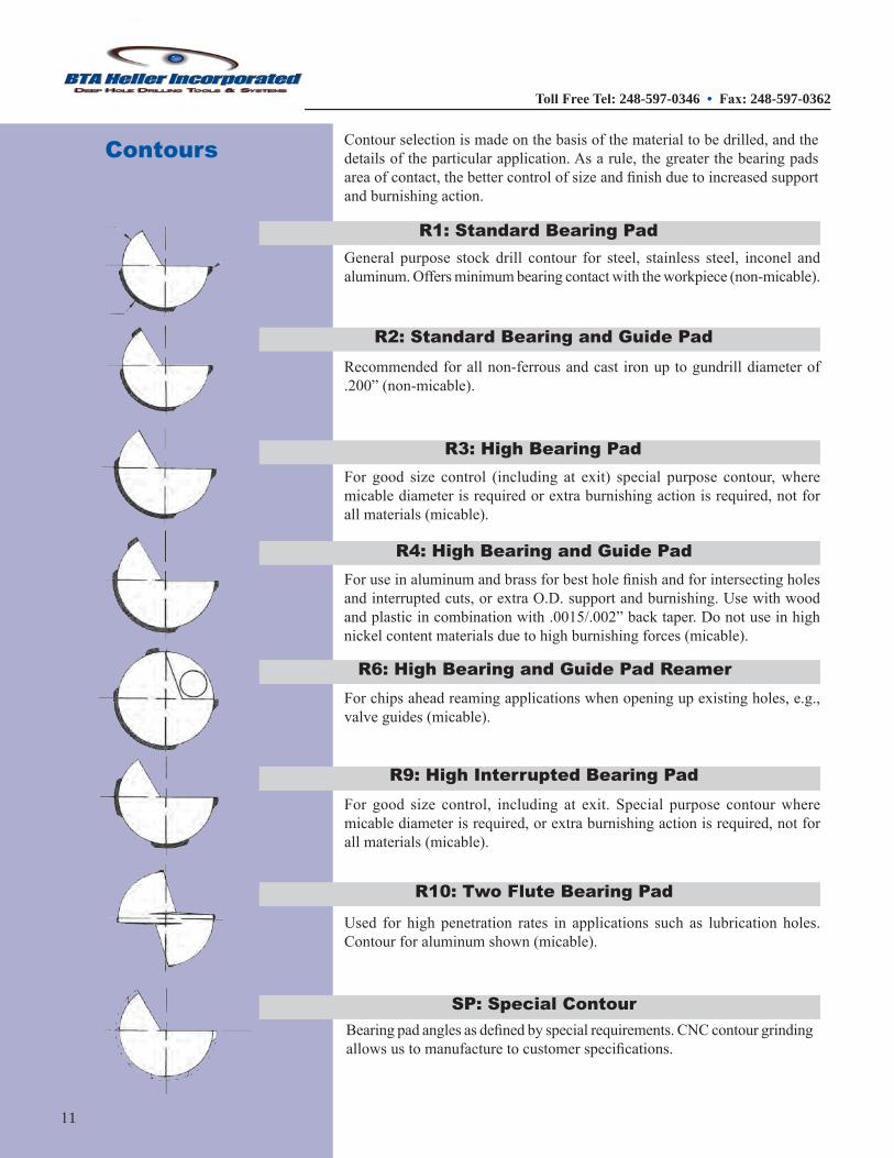
Contours Contourselectionismadeonthebasisofthematerialtobedrilled,andthedetailsoftheparticularapplication.Asarule,thegreaterthebearingpadsareaofcontact,thebettercontrolofsizeandfinishduetoincreasedsupportandburnishingaction.
Bearingpadanglesasdefinedbyspecialrequirements.CNCcontourgrindingallowsustomanufacturetocustomerspecifications.
SP: Special Contour
R10: Two Flute Bearing Pad
Used for high penetration rates in applications such as lubrication holes.Contourforaluminumshown(micable).
R9: High Interrupted Bearing PadFor good size control, including at exit. Special purpose contourwheremicablediameterisrequired,orextraburnishingactionisrequired,notforallmaterials(micable).
R6: High Bearing and Guide Pad ReamerForchipsaheadreamingapplicationswhenopeningupexistingholes,e.g.,valveguides(micable).
Foruseinaluminumandbrassforbestholefinishandforintersectingholesandinterruptedcuts,orextraO.D.supportandburnishing.Usewithwoodandplasticincombinationwith.0015/.002”backtaper.Donotuseinhighnickelcontentmaterialsduetohighburnishingforces(micable).
R4: High Bearing and Guide Pad
R3: High Bearing PadFor good size control (including at exit) special purpose contour,wheremicablediameterisrequiredorextraburnishingactionisrequired,notforallmaterials(micable).
Recommendedforallnon-ferrousandcast ironuptogundrilldiameterof.200”(non-micable).
R2: Standard Bearing and Guide Pad
R1: Standard Bearing PadGeneral purpose stock drill contour for steel, stainless steel, inconel andaluminum.Offersminimumbearingcontactwiththeworkpiece(non-micable).
Toll Free Tel: 248-597-0346 • Fax: 248-597-0362
11

Nosegrinds
Facetgrindsarepreferredonspecificapplications,orwhenregrindfixtureslimitthecamtypesharpenings.
Theycanbegroundtovariousslashtypeangleswithgoodperformanceandallowagreater amountofclearanceforcoolanttocoolthechipatthecuttingedge.This grind is standard onmost Europeanapplications.
ChipBreakers are generally used to breakstringtypechipsoftenattributedtogummymaterialorwhenmachineslimitthesurfacefootagenecessarytogeneratetheheatneededtobreakachip.
TherearetwotypesofChipBreakers:
The Standard Chip Breakeris reproduced each timethetoolisground.
The Radial Chip Breaker runsdown the lengthofthecarbideflatandlaststhelifeofthetool.
STANDARD
RADIAL
Chip Breakers
The center designof ourgundrills allows for awide rangeof nosegrindsfroma full spherical radius toaflatbottomdesign.Thenosegrindanglesare important inattaining thebestqualityresults.Anglescanbemodifiedtoimprovetheflushingactionofthehighpressureoilandtoimprovechipcontrol.Specificgrindshavebeendevelopedforsevereapplicationssuchasexitbreakoutsandinterruptedorangularentries.Someofthemostpopularnosegrindconfigurationsareshownhere.
In aluminum and brass,use this grindwith ‘R4’O.D. contour for bestholefinish.
N-4 Nosegrind
General purpose stockdrill grind for steel,inconel and stainlesssteel, most often usedwith stock ‘R1’ O.D.contour.
N-8 Nosegrind
Fordrilling,stackedpartsandangularentries.Dueto thepoint’s placementnear the center of thedrill,thisisthestrongestgundrill.
N-73 Nosegrind
Forapplicationsrequiringnearly flat bottoms. Itcanalsobegroundforacompletelyflatbottom,orondifficultmaterials,usetoqualifybottomsonly.
N-126 Nosegrind
40/30 FacetDrill Diameters 0.0550 - 0.1575
30/20 FacetDrill Diameters 0.1576 - 0.7874
Facet Nosegrind
Toll Free Tel: 248-597-0346 • Fax: 248-597-0362

K-MONEL WASPALOY, TITANIUM NITRALLOY, HASTELLOY A286,RENE, 718INCONEL GREEKASCOLOY BRASS TUNGSTEN HAYNES MOLLY 400MONEL ETD-150, DUCTILE* BRONZE INCOLOY800-825 INCONEL600,625 NITRONIC40-80 4340 COPPER REFRACTALOY NIMONIC SFM=80 SFM=100 SFM=135 SFM=200 SFM=275 SFM=150 SFM=550 MAX. MAX. MAX. MAX. MAX. MAX. MAX. PSI RPM IPM UNSUP- RPM IPM UNSUP- RPM IPM UNSUP- RPM IPM UNSUP- RPM IPM UNSUP- RPM IPM UNSUP- RPM IPM UNSUP- PORTED PORTED PORTED PORTED PORTED PORTED PORTED LENGTH LENGTH LENGTH LENGTH LENGTH LENGTH LENGTH
0.05500.07810.09370.12500.15620.18750.21870.25000.28120.31250.34370.37500.40620.43750.46870.50000.53120.56250.59370.62500.65620.68750.71870.75000.87501.00001.25001.5000
GUNDRILL
DIAMET
ER
GUNDRILL SPEEDS, FEEDS & COOLANT PRESSURESSTARTING PARAMETERS (Single Flute)
For applications requiring nearlyflat bottoms. It can also grind for acompletely flat bottom.On difficultmaterials,usetoqualifybottomsonly.
N-126 NOSEGRIND
N-73 NOSEGRIND
Fordrilling,stackedpartsandangularentries.Duetothepoint’splacementnearthecenterofthedrill,thisisthestrongestgundrill.
General purpose stock drill grindforsteel,inconelandstainlesssteel,mostoftenusedwithstock‘R1’O.D.diameter.
*Indicates a two flute drill may be used at two times the recommended feed rate
Dia FPR Dia FPR 0.055- 0.00005 0.500- 0.00070 0.078- 0.00010 0.750- 0.00080 0.156- 0.00030 1.000- 0.00100 0.200- 0.00040 1.250- 0.00100 0.250- 0.00050 1.500- 0.00100
RPM = 3.82 x SFMDiameter
FPR = IPR/RPMIPM = FPR x RPM
COOLA
NT
PRES
SURE
N-8NOSEGRIND
N-4NOSEGRIND
In aluminum and brass, use thisgrindwith‘R4’O.D.contourforbestholefinish.
1800 5556 0.3 4.0 6945 0.3 4.0 9376 0.5 4.0 10000 0.5 4.0 10000 0.5 4.0 10000 0.5 4.0 10000 0.5 4.0 1500 3913 0.4 7.2 4891 0.5 6.6 6603 0.7 5.8 9782 1.0 4.6 10000 1.0 4.6 8560 0.9 5.0 10000 1.0 5.0 1500 3261 0.5 9.0 4077 0.6 8.0 5504 0.8 6.5 8154 1.2 3.6 10000 1.5 4.6 7134 1.1 6.1 10000 1.5 5.1 1500 2445 0.4 12.0 3056 0.7 11.0 4126 0.9 9.0 6112 1.4 7.7 8404 1.9 6.5 5348 1.2 8.0 10000 2.3 6.0 1300 1956 0.6 15.3 2446 0.7 13.7 3302 1.0 11.4 4891 1.5 9.7 6725 2.0 8.2 4280 1.3 10.0 10000 3.0 7.1 1150 1630 0.6 18.5 2037 0.7 16.6 2750 1.0 14.0 4075 1.4 11.7 5603 2.0 9.9 3565 1.3 12.2 10000 3.5 7.4 1050 1397 0.6 21.2 1747 0.7 19.0 2358 0.9 15.5 3493 1.4 13.4 4803 1.9 11.4 3057 1.2 14.0 9607 3.8 8.2 925 1222 0.6 24.9 1528 0.8 22.3 2063 1.0 18.5 3056 1.5 15.7 4202 2.1 13.3 2674 1.3 16.4 8404 4.2 9.6 850 1087 0.6 28.0 1358 0.8 24.0 1834 1.1 21.0 2717 1.6 17.7 3736 2.2 15.0 2377 1.4 19.0 7472 4.3 10.8 775 978 0.6 31.2 1222 0.7 28.0 1650 1.0 24.0 2445 1.5 19.7 3362 2.0 16.8 2139 1.3 20.5 6723 4.0 12.0 725 889 0.6 34.4 1111 0.7 30.0 1500 0.9 26.0 2223 1.4 21.7 3056 1.9 18.2 1945 1.2 23.0 6113 3.9 13.3 675 815 0.5 37.0 1019 0.7 33.7 1375 0.9 29.5 2037 1.3 23.0 2801 1.8 20.0 1783 1.2 25.0 5603 3.6 14.5 625 752 0.5 40.8 940 0.6 36.5 1270 0.9 32.0 1881 1.3 25.7 2586 1.8 21.9 1646 1.1 27.3 5172 3.5 15.0 600 699 0.5 44.0 873 0.6 39.5 1179 0.8 35.0 1746 1.2 27.8 2401 1.6 23.6 1528 1.0 29.5 4802 3.3 17.0 550 652 0.5 47.0 815 0.6 42.0 1100 0.8 35.0 1630 1.1 29.8 2241 1.6 25.3 1426 1.0 31.5 4483 3.1 18.2 525 611 0.5 54.0 764 0.5 45.0 1031 0.7 38.0 1528 1.1 31.8 2101 1.5 27.0 1337 0.9 33.6 4202 2.9 19.0 500 575 0.5 55.0 719 0.5 47.9 971 0.7 40.0 1438 1.0 33.8 1978 1.4 28.7 1258 0.9 36.3 3955 2.9 20.5 500 543 0.5 56.0 679 0.5 50.8 917 0.7 42.3 1358 1.0 35.8 1868 1.4 30.4 1188 0.9 39.0 3735 2.7 22.0 475 515 0.4 59.0 643 0.5 53.9 869 0.7 45.0 1287 1.0 38.0 1769 1.3 32.3 1126 0.8 40.7 3539 2.7 23.3 475 489 0.4 63.6 611 0.5 57.0 825 0.6 48.0 1222 0.9 40.2 1681 1.3 34.2 1070 0.8 42.5 3362 2.5 24.6 425 466 0.4 66.8 582 0.5 59.0 786 0.6 50.5 1164 0.9 42.0 1601 1.2 36.0 1019 0.8 45.0 3202 2.5 26.0 425 445 0.4 70.0 556 0.4 62.7 750 0.6 53.0 1111 0.9 44.0 1528 1.2 38.0 972 0.8 50.0 3056 2.4 27.0 400 425 0.4 73.0 532 0.4 65.0 718 0.6 55.0 1063 0.9 46.0 1462 1.2 39.5 930 0.7 51.0 2923 2.3 28.0 400 407 0.4 76.3 509 0.4 68.0 688 0.6 57.0 1019 0.8 48.0 1401 1.1 41.0 891 0.7 52.0 2801 2.2 29.0 350 349 0.4 89.0 437 0.4 79.0 589 0.5 73.0 873 0.8 56.0 1201 1.1 47.0 764 0.7 59.0 2401 2.2 34.0 310 306 0.4 100 382 0.4 91.0 516 0.5 80.0 764 0.8 64.0 1051 1.1 54.0 669 0.7 68.0 2101 2.1 39.0 270 244 0.4 126 306 0.4 113 413 0.5 95.0 611 0.6 80.0 840 0.8 68.0 535 0.5 86.0 1681 1.7 49.0 230 204 0.4 154 255 0.4 138 344 0.5 120 509 0.5 91.0 700 0.7 82.0 446 0.5 105 1401 1.4 60.0
SFM = RPM x Diameter3.82
Toll Free Tel: 248-597-0346 • Fax: 248-597-0362

Foruseinaluminumandbrassforbestholefinishandforintersectingholesand interrupted cuts, or extraO.D.supportandburnishing.(micable).
R-4CONTOUR
R-3CONTOUR
For good size control (including atexit)specialpurposecontour,wheremicablediameterisrequiredorextraburnishingactionisrequired;notforallmaterials(micable).
General purpose stockdrill contourforsteel,stainlesssteel,inconelandaluminum.Offersminimumbearingcontact with theworkpiece (non-micable).
0.055- 0.00005 0.500- 0.00070 0.078- 0.00010 0.750- 0.00080 0.156- 0.00030 1.000- 0.00100 0.200- 0.00040 1.250- 0.00100 0.250- 0.00050 1.500- 0.00100
RPM = 3.82 x SFMDiameter
SFM = RPM x Diameter3.82
FPR = IPR/RPM
IPM = FPR x RPM
R-1CONTOUR
Recommendedforallnon-ferrousandcast iron up to gundrill diameter of.200”(non-micable).
15-5,17-4,13-8,H-13 455CUSTOM 2024AL*,6061AL* 8620 416STAINLESS TOOL 303,304,310,316 7075AL* CAST GRAY 4140,5120 STEEL 341,347,420,501 1010,1118,1145 ALUMINUM* CASTIRON* SFM=550 SFM=325 SFM=175 SFM=200 SFM=550 SFM=600 SFM=200 MAX. MAX. MAX. MAX. MAX. MAX. MAX. RPM IPM UNSUP- RPM IPM UNSUP- RPM IPM UNSUP- RPM IPM UNSUP- RPM IPM UNSUP- RPM IPM UNSUP- RPM IPM UNSUP- PORTED PORTED PORTED PORTED PORTED PORTED PORTED LENGTH LENGTH LENGTH LENGTH LENGTH LENGTH LENGTH
0.05500.07810.09370.12500.15620.18750.21870.25000.28120.31250.34370.37500.40620.43750.46870.50000.53120.56250.59370.62500.65620.68750.71870.75000.87501.00001.25001.5000
GUNDRILL SPEEDS, FEEDS & COOLANT PRESSURESSTARTING PARAMETERS (Single Flute)
*Indicates a two flute drill may be used at two times the recommended feed rate
10000 0.5 4.0 10000 0.5 4.0 10000 0.5 4.0 10000 0.5 4.0 10000 0.5 4.0 10000 0.5 4.0 10000 0.5 4.0
10000 1.0 4.6 10000 1.0 4.6 8560 0.9 4.6 9782 1.0 4.6 10000 1.0 4.6 10000 1.0 4.6 9782 1.0 4.6
10000 1.5 5.0 10000 1.5 5.0 7134 1.1 6.0 8154 1.2 5.0 10000 1.5 5.0 10000 1.5 5.0 8154 1.2 5.0
10000 2.0 6.0 9932 2.0 6.0 5348 1.1 8.0 6112 1.2 7.7 10000 2.0 6.0 10000 2.0 6.0 6112 1.2 7.7
10000 3.0 6.7 7948 2.4 7.7 4280 1.3 10.3 4891 1.5 9.7 10000 3.0 6.6 10000 3.0 6.6 4891 1.5 9.7
10000 3.5 7.5 6621 2.3 9.2 3565 1.2 12.4 4075 1.4 11.7 10000 3.5 7.5 10000 3.5 7.5 4075 1.4 11.7
9607 3.8 8.2 5677 2.3 10.6 3057 1.2 14.2 3493 1.4 13.4 9607 3.8 8.2 10000 4.0 7.8 3493 1.4 13.4
8404 4.2 9.6 4966 2.5 12.4 2674 1.3 16.5 3056 1.5 15.7 8404 4.2 9.6 9168 4.6 9.1 3056 1.5 15.7
7472 4.1 10.8 4415 2.3 14.0 2377 1.2 18.7 2717 1.4 17.7 7472 3.9 10.8 8151 4.2 10.3 2717 1.4 17.7
6723 4.0 12.0 3973 2.4 15.6 2139 1.3 20.9 2445 1.5 19.7 6723 4.0 12.0 7334 4.4 11.5 2445 1.5 19.7
6113 3.9 13.3 3612 2.3 17.2 1945 1.2 23.0 2223 1.4 21.7 6113 3.9 13.3 6669 4.2 12.6 2223 1.4 21.7
5603 3.6 14.5 3311 2.2 18.8 1783 1.2 26.0 2037 1.3 23.2 5603 3.6 14.5 6112 4.0 13.8 2037 1.3 23.2
5172 3.5 15.0 3056 2.1 19.6 1646 1.1 27.3 1881 1.3 25.7 5172 3.5 15.0 5643 3.8 14.2 1881 1.3 25.7
4802 3.3 17.0 2838 1.9 21.9 1528 1.0 29.4 1746 1.2 27.8 4802 3.3 17.0 5239 3.6 16.1 1746 1.2 27.8
4483 3.1 18.2 2649 1.9 23.5 1426 1.0 31.5 1630 1.1 29.8 4483 3.1 18.2 4890 3.4 17.3 1630 1.1 29.8
4202 2.9 19.3 2483 1.7 25.1 1337 0.9 33.7 1528 1.1 31.8 4202 2.9 19.3 4584 3.2 18.5 1528 1.1 31.8
3955 2.9 20.6 2337 1.7 26.7 1258 0.9 35.8 1438 1.0 33.8 3955 2.9 20.6 4315 3.1 19.6 1438 1.0 33.8
3735 2.7 21.9 2207 1.6 28.3 1188 0.9 37.9 1358 1.0 35.8 3735 2.7 21.9 4075 3.0 20.8 1358 1.0 35.8
3539 2.7 23.2 2091 1.6 30.0 1126 0.8 40.2 1287 1.0 38.0 3539 2.7 23.2 3861 2.9 22.1 1287 1.0 38.0
3362 2.5 24.6 1986 1.5 31.8 1070 0.8 42.6 1222 0.9 40.2 3362 2.5 24.6 3667 2.8 23.4 1222 0.9 40.2
3202 2.5 25.8 1892 1.5 37.8 1019 0.8 44.5 1164 0.9 42.2 3202 2.5 25.8 3493 2.7 24.5 1164 0.9 42.2
3056 2.4 27.0 1806 1.4 39.0 972 0.8 46.5 1111 0.9 44.2 3056 2.4 27.0 3334 2.6 25.7 1111 0.9 44.2
2923 2.3 28.2 1727 1.4 41.5 930 0.7 48.7 1063 0.9 46.2 2923 2.3 28.2 3189 2.6 26.8 1063 0.9 46.2
2801 2.2 29.5 1655 1.3 42.7 891 0.7 51.0 1019 0.8 48.2 2801 2.2 29.5 3056 2.4 28.0 1019 0.8 48.2
2401 2.2 34.4 1419 1.3 44.5 764 0.7 59.5 873 0.8 56.2 2401 2.2 34.4 2619 2.4 32.7 873 0.8 56.2
2101 2.1 39.0 1242 1.2 50.9 669 0.7 68.0 764 0.8 64.0 2101 2.1 39.3 2292 2.3 37.0 764 0.8 64.0
1681 1.7 49.0 993 1.0 63.0 535 0.5 84.0 611 0.6 80.0 1681 1.7 50.0 1834 1.8 46.0 611 0.6 80.0
1401 1.4 59.0 828 0.8 77.0 446 0.4 102 509 0.5 91.0 1401 1.4 59.0 1528 1.5 56.0 509 0.5 97.0
R-2CONTOUR
Toll Free Tel: 248-597-0346 • Fax: 248-597-0362
14

Tool Faults Hole Faults
GUNDRILL PROBLEM SOLVING
Possible Outside Wear Built Crater- Margin Flank Poor Tool Tool Tool Poor Hole Tight Bell Banana Out Under- Over- Cause Point Pad Up ing Wear Wear Tool Pick Chip- Break- Finish Run- Exit Mouthed Shaped of sized sized Wear Erosion Edge Life Up ping age out Round Bushing Clamping unsuitable Oversized Undersized Workpiece not against bushing Coolant Incorrect grade Insufficient flow Loss of pressure Overheating High pressure Low pressure Feed Erratic Excessive Insufficient Material Grain structure
Heat treatment faults Overheating and closing In Thin wall section Misalignment Poor Braze Rough Grind On Cutting Edges Spindle Speed high Speed low Tight Hole Tool Built up edge Chip control inadequate Insufficient clearance Incorrect contour (profile) Excessive inside angle pressure Excessive outside angle pressure Incorrect geometry Heel drag Overworked (need regrind) Whip Vibration Mechanical Oil Wear Pad Cutting
Toll Free Tel: 248-597-0346 • Fax: 248-597-0362